

Page 1
036-21105-004 Rev. A (0902)
®
TECHNICAL GUIDE
STELLAR 2000
SPLIT-SYSTEM AIR CONDITIONERS
10 SEER 50 HZ
MODELS: H*DA012 THRU H*DA076
(1 & 3 PHASE)
(1 THRU 7.5 NOMINAL TONS)
Due to continuous product improvement, specifications are subject to change without notice.
Visit us on the web at www.york.com for the most
up-to-date technical information.
DESCRIPTION
The HDA Series condensing unit is the outdoor part of a versatile system of air conditioning. It is designed to be custommatched with one of UPG's complete line of evaporator sections, each designed to serve a specific function. Matching
Air Handlers are available for upflow, downflow or horizontal
application to provid e a com plete syste m. Elec tric he aters a re
available if required.
FEATURES
• QUALITY CONDENSER COILS - The coil is con structed
of enhanced copper tube and aluminum fins.
• COIL PROTECTION - Coils are protected fro m dama ge by
a polymer mesh applied between the coil face, and a PVC
coated steel coil guard.
• PROTECTED COMPRESSOR - The compressor is internally protected against high pressure and temperature.
This is accomplished by the simultaneous operation of
high pressure relief valve and a temperature sensor which
protect the compressor if undesirable operating conditions
occur.
• DURABLE FINISH - Cabinet is made of pre-painted steel.
The pre-treated flat galvanized steel provides a better
paint to steel bond, which resists corrosion and rust creep.
Specia l pri me r form ulas and glossy earth tone finish insure
less fading when exposed to sunlight.
• LOWER INSTALLED COST - Installation time and costs
are reduced by easy power and control wiring connections. Discharge line heat exchanger knockouts are provided, if required. Both quick connect and sweat connect
models are availabl e. Bo th s erv ic e v al ve s a re fi rml y a ffixed
to the unit. The sweat unit contains enough refrigerant for
matching indoor coils and 15 feet of interconnecting piping. The small base dimension means less space is
required on the ground or roof.
• TOP DISCHARGE - The warm air from the top mounted
fan is blown up away from the structure and any landscaping. This allows compact location on multi-unit applications.
• LOW OPERATING SOUND LEVEL - The upward air flow
carries the normal operating noise up away from the living
area. The rigid top panel effectively isolates any motor
sound. Isolator mounted compressor and the rippled fins
of the condenser coil muffle the normal fan motor and
compressor operating sounds.
• LOW MAINTENANCE - Long life permanently lubricated
motor- bearings need no annual servicing.
• EASY SERVICE ACCESS - Fully exposed refrigerant connections and a single pan el cov eri ng the electrical controls
make servicing easy.
• SECURED SERVICE VALVES - Secured re-usable ser-
vice valves are provided on both the liquid and vapor
sweat connections for ease of evacuating and charging.
• FACTORY TESTED - to verify system operation and con-
trol functioning before shipment.
FOR DISTRIBUTION USE ONLY - NOT TO BE USED AT POINT OF RETAIL SALE
Page 2
036-21105-004 Rev. A (0902)
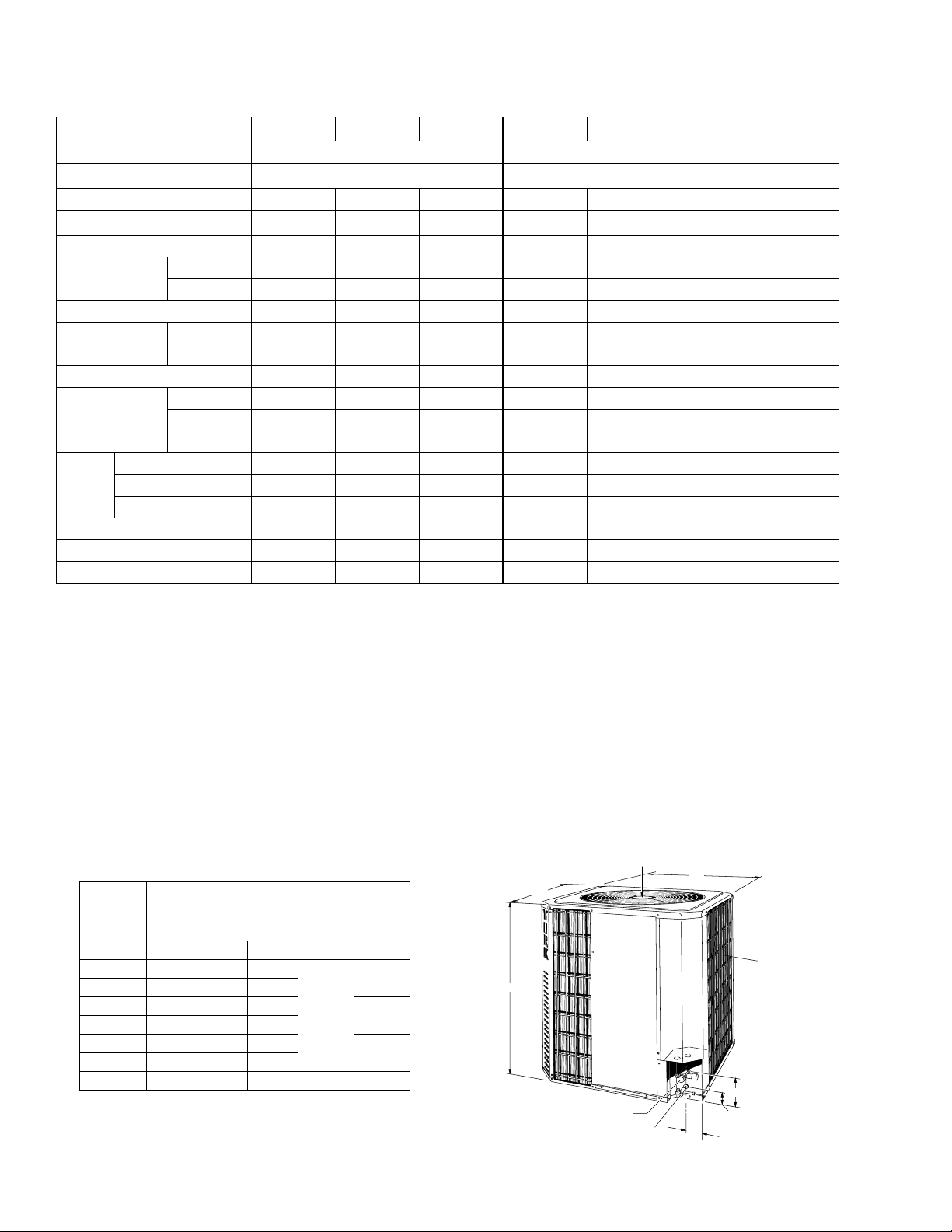
Physical and Electrical Data
MODEL H*DA
Unit Supply Voltage
Normal Voltage Range
Minimum Circuit Ampacity
Max. Overcurrent Device Amps
Compressor Type
Compressor Amps
Crankcase Heater
Fan Motor Amps
Fan Diameter Inches
Fan Motor
Face Area Sq. Ft.
Coil
Rows Deep
Fin / Inches
Liquid Line OD
Vapor Line OD
Operating Weight Lbs.
*. Rated in accordance with ARI Standard 110, utilization range “A”.
†. Dual element fuses or HACR circuit breaker.
** No crankcase heat required due to the compressor’s high pressure housing and internal design.
*
†
Rated Load
Locked Rotor
Rated Load
Locked Rotor
Rated HP
Nominal RPM
Rated Voltage
18 24 30 36 48 60 076
230 – 1 – 50 380/415-3-50
216 to 252 342-456
12.4 16.2 18.4 8.1 12.0 12.7 20.2
20.0 25.0 30.0 15.0 20.0 20.0 30.0
Recip Recip Recip Recip Recip Scroll Scroll
9.2 12.2 13.4 5.8 7.5 9.5 14.7
53.0 72.0 85.0 39.0 62.0 73.0 95.0
No** No** Yes Yes Yes No** No**
0.9 0.9 1.4 0.8 0.8 0.8 1.0
1.4 1.4 3.12 1.8 1.8 2.0 1.8
18 18 18 18 18 24 24
1/8 1/8 1/4 1/4 1/4 1/4 1/3
1075 1075 1100 1075 1075 850 940
230 230 230 460 460 460 415
9.4 9.4 11.3 11.3 14.1 20 20.0
1111112
16 16 20 20 16 18 13
3/8 3/8 3/8 3/8 3/8 3/8 1/2
5/8 5/8 3/4 3/4 7/8 7/8 1-1/8
124 134 135 140 176 210 285
All dimensions are in inches. They are subject to change without
notice. Certified dimensions will be provided upon request.
Unit
Model
H*DA
Dimensions
(Inches)
Refrigerant
Connection
Line Size
A B C Liquid Vapor
018 20-1/8 24 24
024 20-1/8 24 24
030 24-1/8 24 24
036 24-1/8 24 24
048 30-1/8 24 24
060 31-1/8 34-1/2 34-1/2
3/8
5/8
3/4
7/8
B
A
48" OVERHEAD
CLEARANCE
C
AIR IN
4 SIDES
076 34-1/2 34-1/2 31-7/8 1/2 1-1/8
VAPOR
CONNECTION
LIQUID CONNECTION
3-1/8
5-1/2
2-3/8
2 Unitary Products Group
Page 3
036-21105-004 Rev. A (0902)
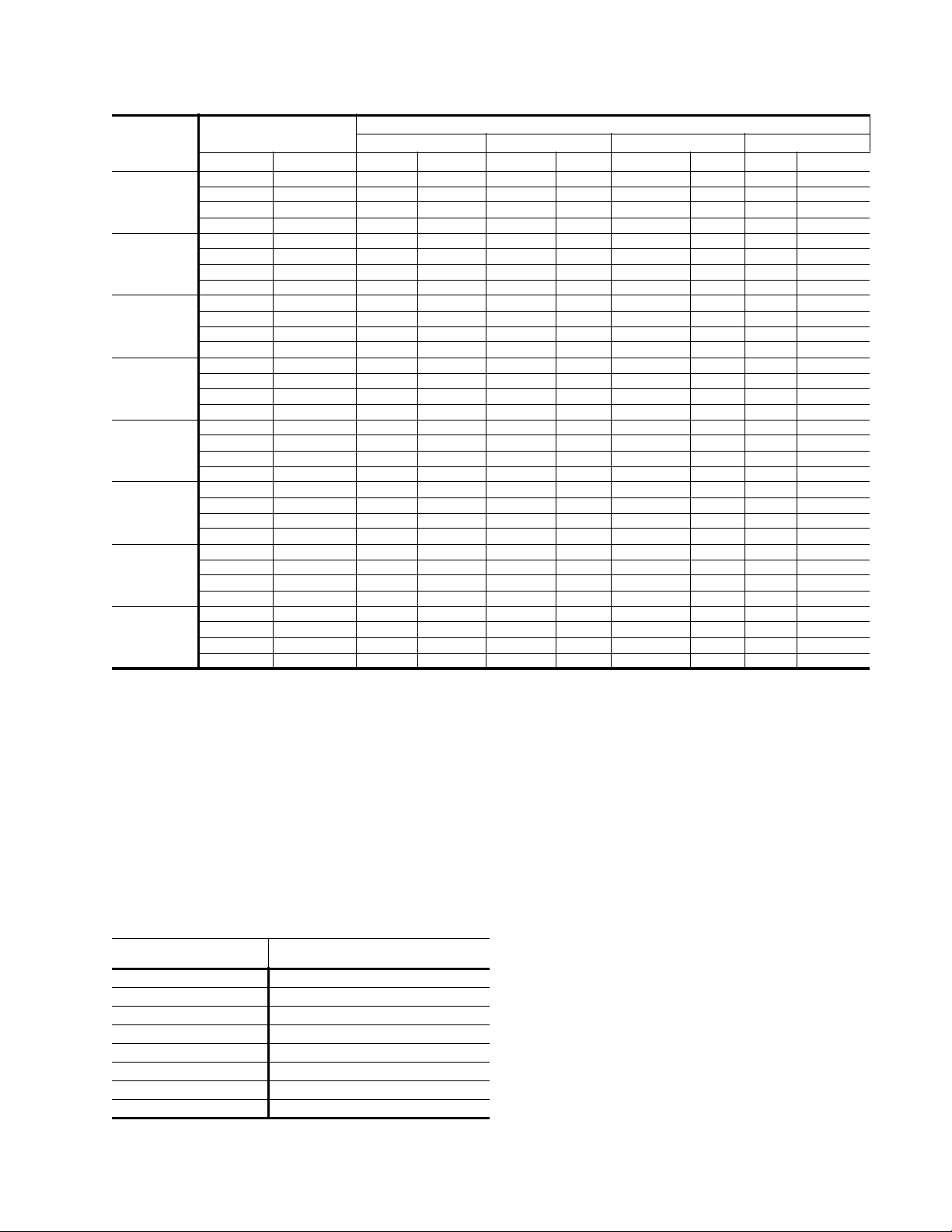
COOLING PERFORMANCE
MODEL
H3DA012
H3DA018
H3DA024
H3DA030
H3DA036
H3DA048
H3DA060
H3DA076
NOTES:
1. For condensing unit only. Does not include effect of evaporator motor power or heat.
2. Performance based on 15° superheat and 15° sub-cooling at condensing unit.
3. Sub-cooling in excess of 20° may result in excessively high condensing temperature with air on condenser above 115°F.
SUCT.T/P @ COMPR.
TEMP PSIG MBH KW MBH KW MBH KW MBH KW
35 61.5 13.0 1.31 10.9 1.41 9.0 1.53 8.0 1.59
40 68.5 14.5 1.36 12.3 1.49 10.2 1.62 9.1 1.69
45 76.0 16.1 1.41 13.7 1.54 11.3 1.69 10.1 1.76
50 84.0 17.7 1.44 15.2 1.58 12.4 1.74 11.1 1.82
35 61.5 18.7 1.83 15.6 1.99 12.5 2.09 10.9 2.13
40 68.5 20.8 1.90 17.6 2.07 14.3 2.20 12.6 2.24
45 76.0 22.9 1.97 19.6 2.17 16.2 2.31 14.5 2.37
50 84.0 25.2 2.05 21.8 2.27 18.3 2.43 16.5 2.49
35 61.5 21.9 2.34 18.7 2.54 15.6 2.71 14.0 2.77
40 68.5 24.3 2.41 20.9 2.63 17.6 2.84 15.9 2.91
45 76.0 26.7 2.47 23.2 2.73 19.7 2.97 18.0 3.06
50 84.0 29.3 2.53 25.6 2.82 21.9 3.10 20.0 3.20
35 61.5 27.6 2.64 23.9 2.88 20.2 3.11 18.3 3.20
40 68.5 30.4 2.71 26.5 2.99 22.5 3.24 20.5 3.34
45 76.0 33.3 2.78 29.2 3.08 25.0 3.37 22.8 3.48
50 84.0 36.3 2.85 31.9 3.18 27.5 3.49 25.5 3.62
35 61.5 33.6 3.07 28.8 3.43 24.0 3.82 21.6 4.01
40 68.5 37.3 3.09 32.1 3.48 26.9 3.88 24.3 4.08
45 76.0 40.9 3.23 35.2 3.69 30.2 4.13 27.5 4.36
50 84.0 44.8 3.37 39.1 3.85 33.3 4.35 30.4 4.60
35 61.5 46.7 3.87 39.1 4.82 31.9 57.8 28.3 6.39
40 68.5 51.7 4.07 43.5 5.08 35.7 6.14 31.8 6.83
45 76.0 56.8 4.28 48 5.34 39.6 6.51 35.4 7.28
50 84.0 62 4.49 52.7 5.6 43.7 6.89 39.2 7.73
35 61.5 53.8 5.16 48.7 6.09 43.4 7.25 40.8 7.92
40 68.5 58.9 5.33 53.1 6.25 47.5 7.41 44.7 8.08
45 76.0 64.1 5.51 57.8 6.43 51.8 7.58 48.7 8.25
50 84.0 69.6 5.71 62.5 6.61 56.1 7.76 52.9 8.43
35 61.5 73.9 5.55 66.2 6.60 58.3 7.98 54.4 8.82
40 68.5 80.7 5.69 72.5 6.75 64.3 8.14 60.2 8.98
45 76.0 87.7 5.84 79.1 6.91 70.5 8.30 66.2 9.15
50 84.0 95.1 5.99 86.1 7.07 76.9 8.48 72.4 9.32
a. Increase capacity 1% for each 2° increase in sub-cooling.
b. Decrease capacity 1% for each 2° decrease in sub-cooling.
Maximum recommended condensing temperature is 140°F.
75 °F 95°F 115°F 125°F
AIR TEMP ON CONDENSER
SOUND RATINGS
H*DA
MODEL
H3DA012 7.8
H3DA018 7.8
H3DA024 7.8
H3DA030 7.8
H3DA036 7.8
H3DA048 8.0
H3DA060 8.2
H3DA076 8.2
Unitary Products Group 3
SOUND RATING
DECIBELS
ACCESSORIES
Refer to Price Manual for specific model numbers.
Off Cycle Timer - Provides a 5 minute off cycle to prevent
rapid recycling of the compressor.
Room Thermostats - A wide selection of matching thermostats is available to provide features required for any installation.
Start Assist Kit - Provides increased starting torque for
areas with low voltage conditions.
Compressor Blanket - Designed to further reduce the normal operating sounds of H3DA units.
Page 4

036-21105-004 Rev. A (0902)
COOLING CAPACITY
AIR HANDLER
UNIT MODEL
1 & 3 PHASE HDA WITH N1AH AIR HANDLER & G2FD COILS
H3DA018S78 N1AHB12 2,5,7.5,10 17 G2FD024S17 650 20.4 14.9 2.23 9.60
H3DA024S78
H3DA0308S78 N1AHB12
H3DA036S50 N1AHB12 5,7.5,10,15,18
H3DA048S50
H3DA060S50 N1AHD20 7.5,10,15,20,25,30 24 G2FD060S24 1800 60.0 43.9 6.45 9.40
1 & 3 PHASE HDA WITH F2RP SINGLE PIECE AIR HANDLERS
H3DA018S78
H3DA024S78 F2RP024 2,5,7.5,10 18 - 850 21.0 15.5 2.5 H3DA030S78 F2RP036 5,7.5,10,15,19 21.5 - 1090 28.0 20.8 3.2 H3DA036S50 F2RP036 5,7.5,10,15,19 21.5 - 1090 35.3 23.8 4.2 8.5
H3DA048S50 F2RP048 10,15,20,25 24 - 1490 42.9 31.7 5.3 8.2
H3DA060S50 F2RP060 10,15,20,25 24 - 1735 54.1 24.5 6.4 8.4
3 PHASE HDA WITH COMMERCIAL BELT DRIVE K*EU EVAPORATOR BLOWER UNIT
H3DA060S50 K2EU060 10,16,25 36 - 2000 55.5 39.5 6.30 10.00
H3DA076S50 K5EU090 10,16,26,36 52 - 2550 74.6 53.7 7.61 9.80
MODEL ELECTRIC HEAT KW W
N1AHB12
N1AHB12 G2FD030S17 800 24.0 17.5 2.79 9.00
N1AHC16 5,7.5,10,15,20 21 G2FD048S21 1550 46.2 34.7 5.06 9.90
N1AHD20 7.5,10,15,20,25,30 24 G2FD048S24 1550 46.2 34.7 5.06 9.90
N1AHD20 7.5,10,15,20,25,30 24 G2FD060S24 1550 47.8 35.9 5.16 9.90
F2RP024
2,5,7.5,10 17
5,7.5,10,15,18 17 G2FD030S17 1025 30.0 21.9 3.32 9.70
- 17 G2FD036S17 1025 30.2 22.0 3.35 9.70
17 G2FD036S17 1200 34.2 24.9 4.05 9.00
21 G2FD046S17 1200 - - - -
2,5,7.5,10 18 - 650 16.9 12.5 2.0 -
COIL MODEL
G2FD024S17 800 23.5 17.1 3.07 8.90
RATED
CFM
COOLING
NET MBH
TOTAL SENS.
KW
SEER
(EER)
MBH based on 80°F entering air temperature, 50% RH, and rated air flow.
KW includes compressor, outdoor fan and indoor blower motor watts. Add-on coils include 365 watts/1000 CFM for blo wer motor.
SEER (Seasonal Energy Efficiency Ratio) is the total cooling output in BTUs during a normal annual usage period for cooling divided
by the total electric power input inwatt-hours during the same period.
(EER) = Energy Efficiency Ratio-steady state total BTUH/electric power input.
4 Unitary Products Group
Page 5

TYPICAL FIELD WIRING
CONTROL
WIRING
LOW VOLTAGE
JUNCTION BOX
ALL OUTDOOR WIRING MUST BE WEATHERPROOF.
USE COPPER CONDUCTORS ONLY.
TYPICAL FIELD WIRING - 1 PHASE
POWER
WIRING
GROUND
LUG
036-21105-004 Rev. A (0902)
GND.
LUG
POWER WIRING
230-1-50
CONTACTOR
TERMINALS
COIL
CONDENSING UNIT
24 VOLT CONTROL WIRING
MINIMUM 18 GA. WIRE
(NEC CLASS 2)
TYPICAL FIELD WIRING - 3 PHASE
POWER WIRING
380/415-3-50
FURNACE OR AIR HANDLER TERMINAL BLOCK
24 VOLT CONTROL WIRING
MINIMUM 18 GA. WIRE
(NEC CLASS 2)
FURNACE OR AIR HANDLER TERMINAL BLOCK
POWER WIRING
CONTROL WIRING
FACTORY WIRING
CYRGW
YRGW
ROOM THERMOSTAT
*
POWER WIRING
CONTROL WIRING
FACTORY WIRING
*
TERMINAL W IS
ONLY REQUIRED
ON SYSTEMS
WITH HEAT.
CYRGW
TERMINAL W IS
*
ONLY REQUIRED
CONTACTOR
TERMINALS
GND.
LUG
CONDENSING UNIT
Unitary Products Group 5
COIL
YRGW
ROOM THERMOSTAT
ON SYSTEMS
WITH HEAT.
*
Page 6

036-21105-004 Rev. A (0902)
TYPICAL INSTALLATION
THERMOSTAT
TO
POWER
TO
INDOOR
BLOWER
TO COIL
NOTE: All outdoorwiringmust be weatherproof
SUPPLY
NEC
CLASS 2
WIRING
MATCHIN G INDOOR COMPONENTS
WEATHERPROOF
DISCONNECT
SWITCH
NEC
CLASS 1
WIRING
24” SERVICE ACCESS
CLEARANCE
Seal opening(s) with permagum
or equivalent
ADD-ON COILS - FOR FURNACE APPLICATIONS
48” OVERHEAD
CLEARANCE
12” REAR AND
SIDES
N1AH
MODULAR BLOWER
(UPFLOW, HORIZONTAL
AND DOWNFLOW)
G2FD*
MULTI-POSITION
(UPFLOW, HORIZONTAL
AND DOWNFLOW)
AIR HANDLERS - FOR NON-FURNACE APPLICATIONS
K*EU060,090
LIGHT COMMERCIAL
APPLICATIONS
G2FD
COIL
F2RP
FAN COIL UNITS
(UPFLOW, HORIZONTAL)
6 Unitary Products Group
Page 7

NOTES
036-21105-004 Rev. A (0902)
Unitary Products Group 7
Page 8

Subject to change without notice. Printed in U.S.A. 036-21105-004 Rev. A (0902)
Copyright © by York International Corp. 2002. All rights reserved. Supersedes: 036-21105-003 Rev. C (0901)
Unitary 5005 Norman
Product York OK
Group Drive 73069
 Loading...