

S
CO
S
550.37-N1Y (594)
Product Category
®
CAUTION
THE ENCLOSED INSTALLAT I ON INSTRUCTI ONS AND ANY APPL I CABL E
LOCAL, STATE, AND NATIONAL CODES I NCLUDING, BUT NOT LIMITED
TO, BUILDING, ELECTRICAL, AND MECHANICAL CODES.
THIS PRODUCT MUST BE INSTALLED IN STRICT COMPLIANCE WITH
WARNING
OPERATION OF THE PRODUCT COULD CAUSE PERSONAL INJURY
OR PROPERTY DAM AGE.
I NCORRECT INSTALLATION MAY CREATE A CONDITION WHERE THE
TELLAR ULTRA
SPLIT-SYSTEM COOLING
3 and 5 TONS
NDENSING UNIT
INSTALLATION INSTRUCTION
MODELS H1DS036, H1DS048 and H1DS060
GENERAL
This instruction covers the installation of the following Stellar
ULTRA high efficiency condensin g units.
H1DS036S06
H1DS048S06
H1DS060S06
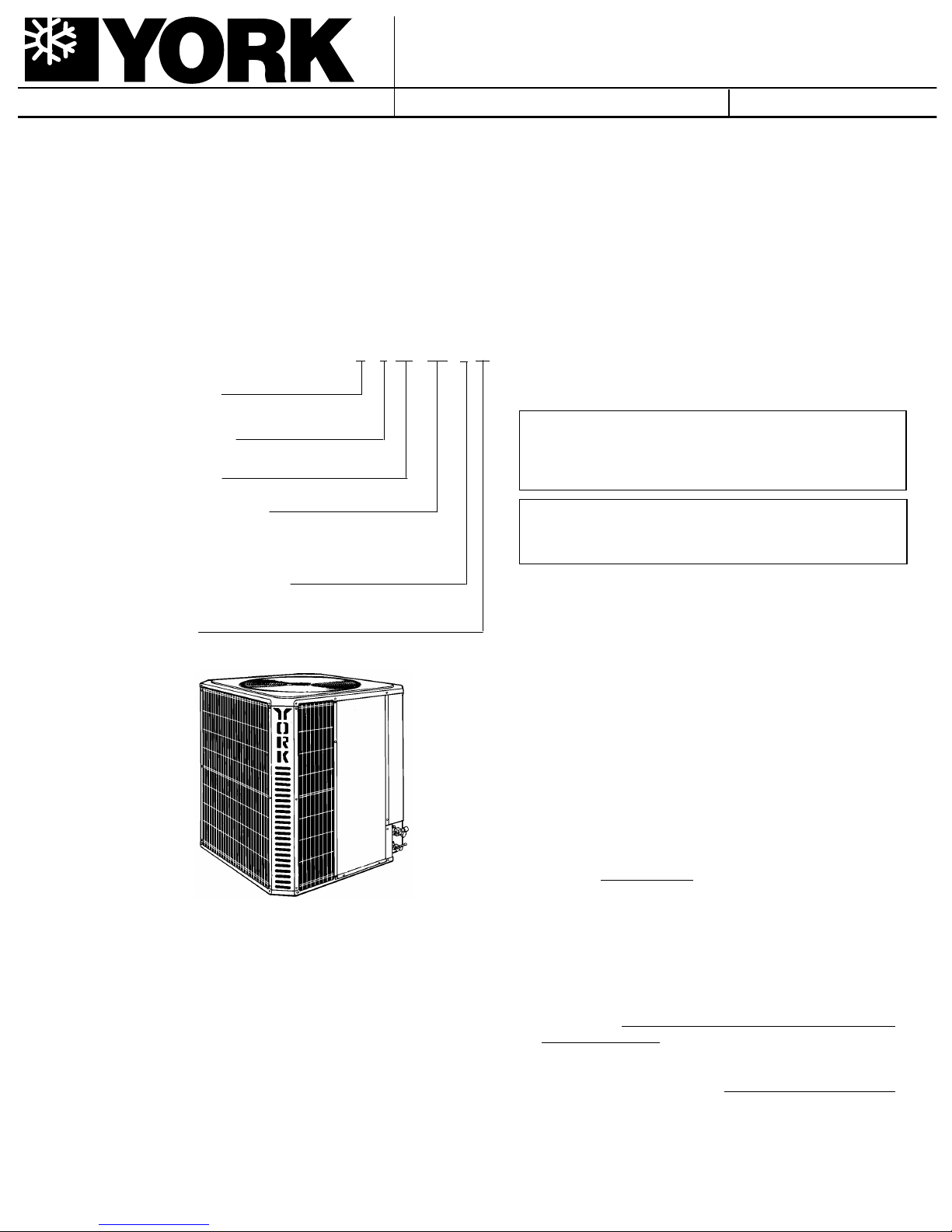
NOMENCLA T URE
H = Condensing Unit
Product Generation
1 = Design Level
Product Identifier
DS = 16.00 SEER Condensing Unit
Nominal Cooling Capacity
036=36,000 BTUH 048=48,000 BTUH
060=60,000 BTUH
Supersedes: 550.37-N1Y (793)
DS
H 036S061
035-10821
Installer should pay particular attention to the words:NOTE,
CAUTION and WARNING.
NOTES are intended t o cla rif y or make the ins t allat ion easier.
CAUTIONS are given to preve nt equipmen t dama ge.
WARNINGS ar e given to alert the inst aller that personal injury
and/or e quipment damag e may r esult if ins tallatio n proc edures
are not handled properly.
Refrigerant Line Connections
S = Sweat-Connect
Voltage Code
06 = 208/230-1-60
The outdoor condensing unit s are designed to be installed with
corresponding variable speed air handlers and a corresponding coil with sweat connect lines. Each unit is factory charged
with refrigerant sufficient for the s mallest indoor evap orator coil
plus 15 feet of field sup plied vapor and li quid lines. A b alanced
port hard shut-off TXV kit must be used for optimum system
performance.
SAFETY
Use this instruction in conjunction with the instruction for the
appropria te indo or eva porat or coi l, variab le s peed air hand ler and
other acc essor ies. Re ad a ll ins tru ction s be fo re ins ta lling th e uni t.
INSPECTION
As soon as a unit is rece ived, it should be inspec ted for possible
damage during transit. If damage is evident, the extent of the
damage should be not ed on the carrier’s freight bill. A separat e
request for inspec tion by the carrier’ s agent should be made in
writing. See Form 50.15-NM for more info rmat ion.
LIMITATIONS
The unit should be installed in accordance wit h all national and
local safety codes an d the limit ations listed below:
1. Limitations for the indoor unit, coil and appropriate accessories must also be obs erv ed.
2. This unit
handler or furnac e sys tem.
3. The outdoor unit must not be ins talled with any ductwor k in
the air stream. The o ut door fan is t he pro pelle r type and is
not designed to operate against any additional external
stati c pressur e.
4. The unit should not be operated at outdoor temperatures
below 60 °F.
low ambient kit.
operate with an y type of low amb ient kit.
5. Indoor evaporator coil orifice
the installation of a factory s upplied balanc ed port TXV kit.
should not be
The unit is not designed to operate with a
installed with a single speed air
Do not modify the control system to
must be removed prior to
550.37-N1Y
TABLE 1 - PHYSICAL AND ELECT RIC AL DATA
UNIT SUPPLY VOL T AGE 208/230-1-60
NORMAL VOLT AGE RANGE
MI N. C IR C UI T A MPAC I TY 20 25.9 30.5
MAX. OVERCURRENT DEVICE AMPS
COMPRESSOR # 1 AMPS
(Lead Compressor)
COMPRESSOR # 2 AMPS
(Follower Compressor)
CRANKCASE HEATER YES YES YES
FA N MOT OR A MPS
MIN. FIEL D WIRE SIZ E AW G
60°C COPPER CONDUCTORS
MAX. WIRE LENGTH FEET
BASED ON 3% VOLTAGE DROP
FAN DIAMETER INCHES 24 24 24
FAN MOTOR
COIL
LI Q UID LI N E O D 3/8 3/8 3/8
VAPO R L I N E O D 7/8 7/8 7/8
OP E R ATI N G W E I G H T L B S . 277 282 340
1
Utilization range “A” in accordance with ARI standard 110.
2
Dual element fuses or HACR circuit breaker.
MODEL H1DS... 036 048 060
1
2
25 35 40
187 to 252
RATE D L OAD 8.3 8.3 10.9
LOCKED ROTOR 48 48 64
RATE D L OAD 9.0 13.5 15.1
LO C KE D RO T O R 48 68 81.0
RATE D L OAD 0.7 0.7 0.7
LO C KE D RO T O R 0.8 0.8 0.8
10 10 8
208V 125 100 100
230V 140 115 110
RATE D H P 1/10 1/10 1/10
NO M I N A L RPM 825 825 825
NO M I N A L CFM 2800 2800 2700
F A CE A R EA SQ . F T. 23.5 23.5 23.5
ROWS DEEP 1 1 2
FI N / I NC H 20 20 16
TO
THERMOSTAT
BLOWER
MOTOR
RELAY
TO POWER
SUPPLY
NEC CLASS 2
WIRING
TO
COIL
NOTE: ALL OUTDOOR WIRING MUST
BE WEATHERPROOF
SEAL OPENING(S) WITH PERMAGUM OR EQUIVALENT
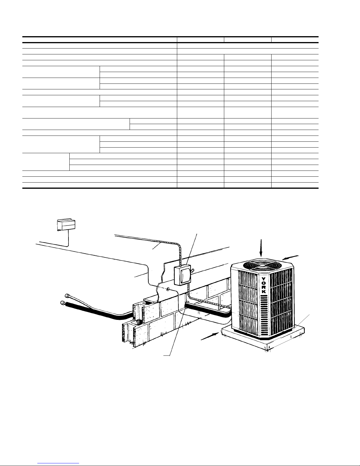
FIGURE 1- TYPICAL INSTALLATION
NEC CLASS 1
WIRING
WEATHERPROOF
DISCONNECT
SWITCH
24" SERVICE
ACCESS CLEARANCE
REQUIRED
48" OVERHEAD
CLEARANCE
REQUIRED
12" REAR AND
SIDES
CLEARANCE
REQUIRED
Sit unit on
rubber
elevator
grommets
to reduce
noise and
allow for
proper
drainage.
2 Central Environmental Systems
550.37-N1Y
LOCA TION
Before startin g th e ins ta llat ion , sele ct and che ck the s uit ability
of the location for both the indoor and outdoor unit . Observe all
limitations and clearan ce re quire ment s.
The outdoor unit must have suf ficient clearance fo r air entrance
to the condens er coil, for air dis charge a nd for s ervic e access.
See Figure 1.
If the unit is to be installed on a hot sun exposed roof or a
black-topped grou nd area, the unit s hould be raised suf ficient ly
above the roof or ground to avoid taking the accumula ted layer
of hot air in to the outdoor u nit.
Provide an adequat e s truc tu ral s uppo rt.
GROUND INSTALLATION
The unit may be installed at ground level on a solid base that
will not shift or settle, causing strain on the refriger ant lines and
possible leaks. Maintain the clearanc es shown in Figure 1 and
install the uni t in a level position. Isolate the base from the
structure to avoid noise or vibration tr ans mi ssion .
Isolate the unit from rain gu tters to avoid any possible wash out
of the foundation.
Normal operating sound levels may be objectionab le if the unit
is placed directly under wi ndows of certa in rooms (bedrooms ,
study, etc.).
ROOF INSTALLATION
When installing units on a roof, the structure must be capable
of supporting the tot al weight of the unit, including a pad, lint els,
rails, etc., which should be used to minimize the transmission
of sound or vibration int o the conditioned space.
UNIT PLACEMENT
1. Provide a base in the pre-de termined lo cat io n.
2. Remove the shipping carton and inspec t for possible damage.
3. Compressor tie-down bolts should rema in ti ght ene d.
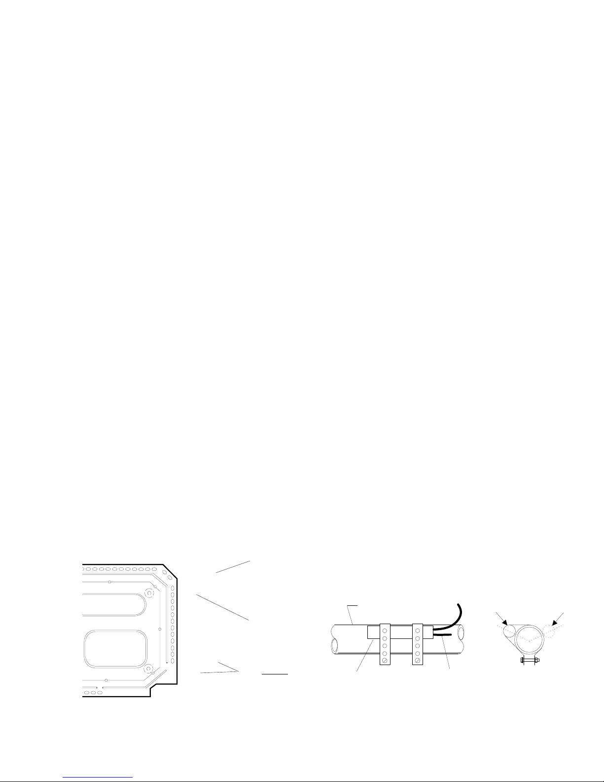
UNIT
BASE
PAN
4. Position t he uni t on the base prov ided .
5. Sit unit on the (4) rub ber elev ating grommets prov ided with
the unit. These sho uld be pos it ion ed as shown in Figure 2
to reduce noise an d allow for prop er drainage.
6. Make a hole(s) in the structure wall large enough to accomodate the insulat ed vapor lin e, the liquid lin e an d the wiring.
TXV INSTALLA TION
This condensing unit requires the installation of a thermal
expansion valve. The TXV controls the superheat of the
refrigerant at the outlet of the evaporator coil, ensuring the
proper refrigerant temperature at the suction of compressor.
Following are the basic steps for installing the TXV. For detail
instruct ions, r efer to the I nstallat ion I nstruc tions accomp anying
the TXV kit.
Install TXV kit as follows:
1. Position the interconnecting refrigerant lines for proper
installation to the outdoor condensing unit and the indoor
evaporator coil, but do not make any connections at this
time.
WARNING:The evaporator coil is under 15 psig pressure .
2. Crack open the liquid lin e fitting of the ind oor coil to relie ve
pressure. This fitting is left handed thread. Turn clockwise
to open.
3. Remove the fit t ing.
4. Using a small diameter wire, remove the orifice from the
other half of the liqu id line fitting .
NOTE: Orifice is not used when the TXV assembly is installed.
5. Reinstall the liquid line fitting hand tight and turn an additional 1/8 turn to seal well.
6. Insert a nd braze t he TXV outlet connec tion to t he liquid line
flare fittin g mount ed on the evaporat or coil.
7. Connect external equalizer t ube to t he vapor line.
8. Position sensing bulb on horizontal portion of vapor line.
Secure using the clamps fur nis hed in th e kit. S ee Fig ure 3.
for positioning of the bulb. Insulate bulb after ins tallation.
FIGURE 2 - POSITIONING GROMMETS
Central Environmental Systems 3
RUBBER
ELEV ATING
GROMMETS
(4)
Note: Do Not block
drainage holes with
grommets.
7/8" VAPOR LINE
SENSING
BULB
ROTATE BULB TO KEEP
TAIL AT BOTTOM
10 O'CLOCK
FIGURE 3 - CORRECT BULB LO C ATIONS
OR
END VIEW
2 O'CLOCK
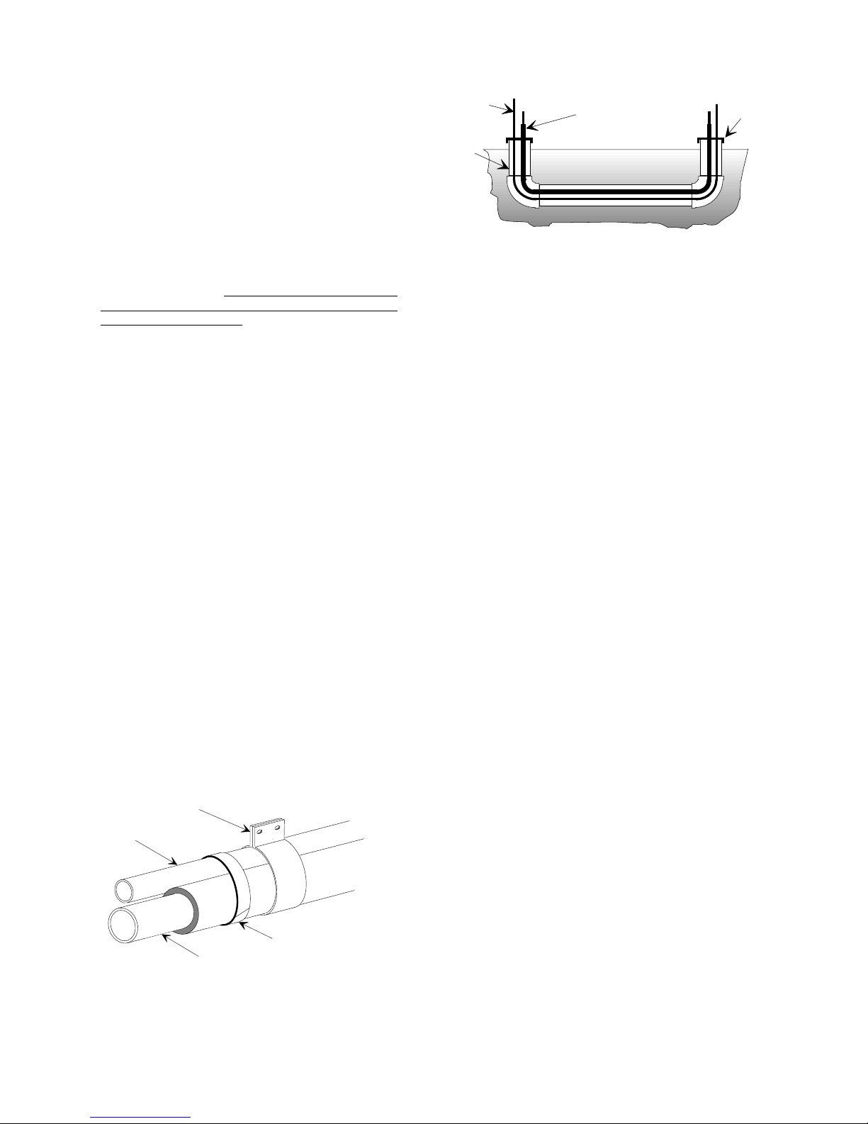
LIQUID
LINE
TAPE
SHEET
METAL
HANGER
INSULA T ED
VAPOR LIN E
TO INDOOR COIL
TO OUTDOOR UNIT
LIQUID LINE
CAP
PVC
CONDUIT
INSULATED
VAPOR LINE
550.37-N1Y
PIPING CONNECTIONS
The outdoor condensing unit may be connected to the indoor
evaporator coil using field supplied refrigerant grade copper
tubing that i s internally clean an d dry . Units should be ins talled
only with the tubing sizes for approved system combinations
as specified in Table 5. The charge g iven is appl icable f or total
tubing lengths up to 15 feet. See Application Data Form 690.01AD1V for installing tubing of longer lengths and elevation
differences.
NOTE: Using a larger than specified line size could result in
oil return problems. Us ing too small a line will result in
loss of capac ity and other p roblems caused by insu fficient refrigerant flow.
Slope horizontal vapor lines at
least 1" every 20 feet toward the outdoor unit to
facilitate pro per oil re tu rn.
PRECAUTIONS DURING LINE INSTALLATI ON
1. Install the lines with as few bends as possible. Care must
be taken not to damage the couplings or kink the tubing.
Use clean hard drawn copper tubing where no appreciable
amount of bending around obstruction is necessary. If soft
copper must be used, care must be taken to avoid sharp
bends which ma y caus e a rest ric tion.
2. The lines should be installed so that they will not obstruct
service acce ss to th e coil, air hand ling s yst em or filt er.
3. Care must also be taken to isolate the refrigerant lines to
minimize noise transmission from the equip ment to the structure.
4. The vapor line must be insulated with a minimum of 1/2"
foam rubber insulation (Arm-A-Flex or equivalent). Liquid
lines that will be exposed to direct sunlight and/or high
temperatures must als o be insulated.
5. Tape and suspend the refrigerant lines as s hown. DO NO T
allow metal-to met al cont ac t. See Figure 4.
6. Use PVC piping as a conduit for all underground installations as shown in Figure 5. Buried lines shoul d be kept as
short as possible to minimize the build up of liquid refrigerant in the vapor line durin g long p eriods of sh utdown.
FIGURE 5 - UNDERGROUND INSTALLATION
7. Pack fiber glass insulation and a sealing material such as
permagum around ref rigerant line s where they penet rate a
wall to reduce vi brat ion and t o retain s ome f lex ibili ty.
8. See Form 690.01-AD1V for additional piping information.
PRECAUTIONS DURING BRAZING OF LINES
All outdoor uni t and evaporat or coil c onnections are c opper-to-
copper and should be brazed with a phosphor ous-copper alloy
material such as Silfos-5 or equivalent. DO NOT use soft
solder.
CAUTION: Dry nitrogen should always be supplied through the
tubing while it is bein g brazed, because the temperature required is high enough t o cause oxidation of t he
copper unless an inert atmosphere is provided. The
flow of dry nitrogen should continue until the joint has
cooled. Always use a pressure regulator and safety
valve to insure tha t only low pressure dry nit rogen is
introduced into the tubing. Only a small flow is necessary to displace air and prevent oxidation.
The outdoor units have re-usable service valves on both the
liquid and vapor connections. The total system refrigerant
charge is retained within the outdoor unit during shipping and
installation. The re-usable service valves are provided to
evacuate and cha rge pe r thi s inst ruc t ion.
Serious service problems can be avoided by taking adequate
precautions to assure an internally clean and dry system.
PRECAUTIONS DURING BRAZING ANGL E VALVE
FIGURE 4 - TUBING HANGER
4 Central Environmental Systems
Precautions should be taken to prevent heat damage to angle
valve by wrapping a wet rag around it as shown in Figure 6.
Also, protect al l painted surfaces and in sulation during brazing.
After brazing - cool joint with wet rag.
WARNING: This is not a backseating v alve. The service access
port has a valve core. Opening or closing valve
does not close serv ice access p ort.
V alve can be opened by removing t he plunger cap (See Figure
7) and fully inserting a hex wrench into the stem and backing
out counter-clockwise until valve stem just touch es retaining ring.
 Loading...