

Page 1
S
CO
S
550.37-N1Y (594)
Product Category
®
CAUTION
THE ENCLOSED INSTALLAT I ON INSTRUCTI ONS AND ANY APPL I CABL E
LOCAL, STATE, AND NATIONAL CODES I NCLUDING, BUT NOT LIMITED
TO, BUILDING, ELECTRICAL, AND MECHANICAL CODES.
THIS PRODUCT MUST BE INSTALLED IN STRICT COMPLIANCE WITH
WARNING
OPERATION OF THE PRODUCT COULD CAUSE PERSONAL INJURY
OR PROPERTY DAM AGE.
I NCORRECT INSTALLATION MAY CREATE A CONDITION WHERE THE
TELLAR ULTRA
SPLIT-SYSTEM COOLING
3 and 5 TONS
NDENSING UNIT
INSTALLATION INSTRUCTION
MODELS H1DS036, H1DS048 and H1DS060
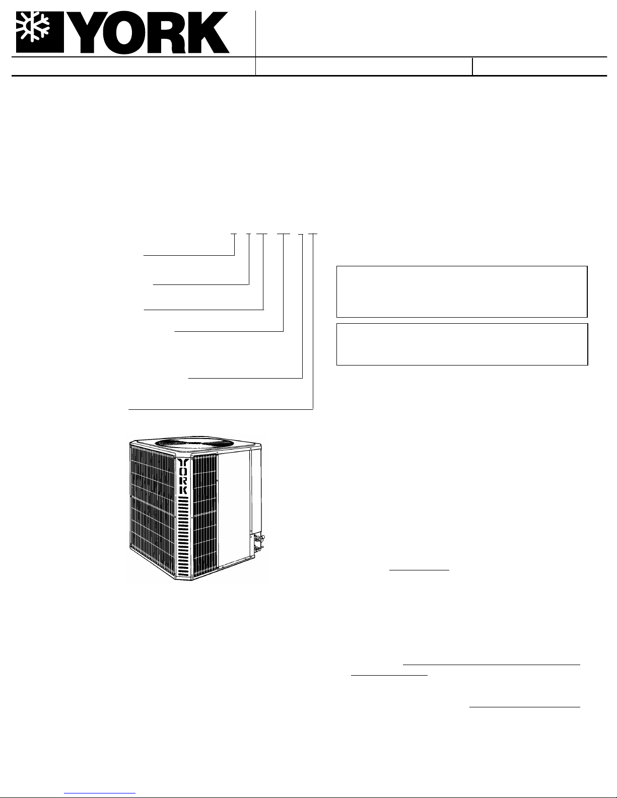
GENERAL
This instruction covers the installation of the following Stellar
ULTRA high efficiency condensin g units.
H1DS036S06
H1DS048S06
H1DS060S06
NOMENCLA T URE
H = Condensing Unit
Product Generation
1 = Design Level
Product Identifier
DS = 16.00 SEER Condensing Unit
Nominal Cooling Capacity
036=36,000 BTUH 048=48,000 BTUH
060=60,000 BTUH
Supersedes: 550.37-N1Y (793)
DS
H 036S061
035-10821
Installer should pay particular attention to the words:NOTE,
CAUTION and WARNING.
NOTES are intended t o cla rif y or make the ins t allat ion easier.
CAUTIONS are given to preve nt equipmen t dama ge.
WARNINGS ar e given to alert the inst aller that personal injury
and/or e quipment damag e may r esult if ins tallatio n proc edures
are not handled properly.
Refrigerant Line Connections
S = Sweat-Connect
Voltage Code
06 = 208/230-1-60
The outdoor condensing unit s are designed to be installed with
corresponding variable speed air handlers and a corresponding coil with sweat connect lines. Each unit is factory charged
with refrigerant sufficient for the s mallest indoor evap orator coil
plus 15 feet of field sup plied vapor and li quid lines. A b alanced
port hard shut-off TXV kit must be used for optimum system
performance.
SAFETY
Use this instruction in conjunction with the instruction for the
appropria te indo or eva porat or coi l, variab le s peed air hand ler and
other acc essor ies. Re ad a ll ins tru ction s be fo re ins ta lling th e uni t.
INSPECTION
As soon as a unit is rece ived, it should be inspec ted for possible
damage during transit. If damage is evident, the extent of the
damage should be not ed on the carrier’s freight bill. A separat e
request for inspec tion by the carrier’ s agent should be made in
writing. See Form 50.15-NM for more info rmat ion.
LIMITATIONS
The unit should be installed in accordance wit h all national and
local safety codes an d the limit ations listed below:
1. Limitations for the indoor unit, coil and appropriate accessories must also be obs erv ed.
2. This unit
handler or furnac e sys tem.
3. The outdoor unit must not be ins talled with any ductwor k in
the air stream. The o ut door fan is t he pro pelle r type and is
not designed to operate against any additional external
stati c pressur e.
4. The unit should not be operated at outdoor temperatures
below 60 °F.
low ambient kit.
operate with an y type of low amb ient kit.
5. Indoor evaporator coil orifice
the installation of a factory s upplied balanc ed port TXV kit.
should not be
The unit is not designed to operate with a
installed with a single speed air
Do not modify the control system to
must be removed prior to
Page 2
550.37-N1Y
TABLE 1 - PHYSICAL AND ELECT RIC AL DATA
UNIT SUPPLY VOL T AGE 208/230-1-60
NORMAL VOLT AGE RANGE
MI N. C IR C UI T A MPAC I TY 20 25.9 30.5
MAX. OVERCURRENT DEVICE AMPS
COMPRESSOR # 1 AMPS
(Lead Compressor)
COMPRESSOR # 2 AMPS
(Follower Compressor)
CRANKCASE HEATER YES YES YES
FA N MOT OR A MPS
MIN. FIEL D WIRE SIZ E AW G
60°C COPPER CONDUCTORS
MAX. WIRE LENGTH FEET
BASED ON 3% VOLTAGE DROP
FAN DIAMETER INCHES 24 24 24
FAN MOTOR
COIL
LI Q UID LI N E O D 3/8 3/8 3/8
VAPO R L I N E O D 7/8 7/8 7/8
OP E R ATI N G W E I G H T L B S . 277 282 340
1
Utilization range “A” in accordance with ARI standard 110.
2
Dual element fuses or HACR circuit breaker.
MODEL H1DS... 036 048 060
1
2
25 35 40
187 to 252
RATE D L OAD 8.3 8.3 10.9
LOCKED ROTOR 48 48 64
RATE D L OAD 9.0 13.5 15.1
LO C KE D RO T O R 48 68 81.0
RATE D L OAD 0.7 0.7 0.7
LO C KE D RO T O R 0.8 0.8 0.8
10 10 8
208V 125 100 100
230V 140 115 110
RATE D H P 1/10 1/10 1/10
NO M I N A L RPM 825 825 825
NO M I N A L CFM 2800 2800 2700
F A CE A R EA SQ . F T. 23.5 23.5 23.5
ROWS DEEP 1 1 2
FI N / I NC H 20 20 16
TO
THERMOSTAT
BLOWER
MOTOR
RELAY
TO POWER
SUPPLY
NEC CLASS 2
WIRING
TO
COIL
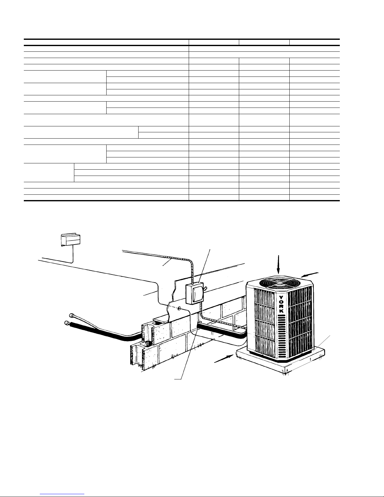
NOTE: ALL OUTDOOR WIRING MUST
BE WEATHERPROOF
SEAL OPENING(S) WITH PERMAGUM OR EQUIVALENT
FIGURE 1- TYPICAL INSTALLATION
NEC CLASS 1
WIRING
WEATHERPROOF
DISCONNECT
SWITCH
24" SERVICE
ACCESS CLEARANCE
REQUIRED
48" OVERHEAD
CLEARANCE
REQUIRED
12" REAR AND
SIDES
CLEARANCE
REQUIRED
Sit unit on
rubber
elevator
grommets
to reduce
noise and
allow for
proper
drainage.
2 Central Environmental Systems
Page 3
550.37-N1Y
LOCA TION
Before startin g th e ins ta llat ion , sele ct and che ck the s uit ability
of the location for both the indoor and outdoor unit . Observe all
limitations and clearan ce re quire ment s.
The outdoor unit must have suf ficient clearance fo r air entrance
to the condens er coil, for air dis charge a nd for s ervic e access.
See Figure 1.
If the unit is to be installed on a hot sun exposed roof or a
black-topped grou nd area, the unit s hould be raised suf ficient ly
above the roof or ground to avoid taking the accumula ted layer
of hot air in to the outdoor u nit.
Provide an adequat e s truc tu ral s uppo rt.
GROUND INSTALLATION
The unit may be installed at ground level on a solid base that
will not shift or settle, causing strain on the refriger ant lines and
possible leaks. Maintain the clearanc es shown in Figure 1 and
install the uni t in a level position. Isolate the base from the
structure to avoid noise or vibration tr ans mi ssion .
Isolate the unit from rain gu tters to avoid any possible wash out
of the foundation.
Normal operating sound levels may be objectionab le if the unit
is placed directly under wi ndows of certa in rooms (bedrooms ,
study, etc.).
ROOF INSTALLATION
When installing units on a roof, the structure must be capable
of supporting the tot al weight of the unit, including a pad, lint els,
rails, etc., which should be used to minimize the transmission
of sound or vibration int o the conditioned space.
UNIT PLACEMENT
1. Provide a base in the pre-de termined lo cat io n.
2. Remove the shipping carton and inspec t for possible damage.
3. Compressor tie-down bolts should rema in ti ght ene d.
UNIT
BASE
PAN
4. Position t he uni t on the base prov ided .
5. Sit unit on the (4) rub ber elev ating grommets prov ided with
the unit. These sho uld be pos it ion ed as shown in Figure 2
to reduce noise an d allow for prop er drainage.
6. Make a hole(s) in the structure wall large enough to accomodate the insulat ed vapor lin e, the liquid lin e an d the wiring.
TXV INSTALLA TION
This condensing unit requires the installation of a thermal
expansion valve. The TXV controls the superheat of the
refrigerant at the outlet of the evaporator coil, ensuring the
proper refrigerant temperature at the suction of compressor.
Following are the basic steps for installing the TXV. For detail
instruct ions, r efer to the I nstallat ion I nstruc tions accomp anying
the TXV kit.
Install TXV kit as follows:
1. Position the interconnecting refrigerant lines for proper
installation to the outdoor condensing unit and the indoor
evaporator coil, but do not make any connections at this
time.
WARNING:The evaporator coil is under 15 psig pressure .
2. Crack open the liquid lin e fitting of the ind oor coil to relie ve
pressure. This fitting is left handed thread. Turn clockwise
to open.
3. Remove the fit t ing.
4. Using a small diameter wire, remove the orifice from the
other half of the liqu id line fitting .
NOTE: Orifice is not used when the TXV assembly is installed.
5. Reinstall the liquid line fitting hand tight and turn an additional 1/8 turn to seal well.
6. Insert a nd braze t he TXV outlet connec tion to t he liquid line
flare fittin g mount ed on the evaporat or coil.
7. Connect external equalizer t ube to t he vapor line.
8. Position sensing bulb on horizontal portion of vapor line.
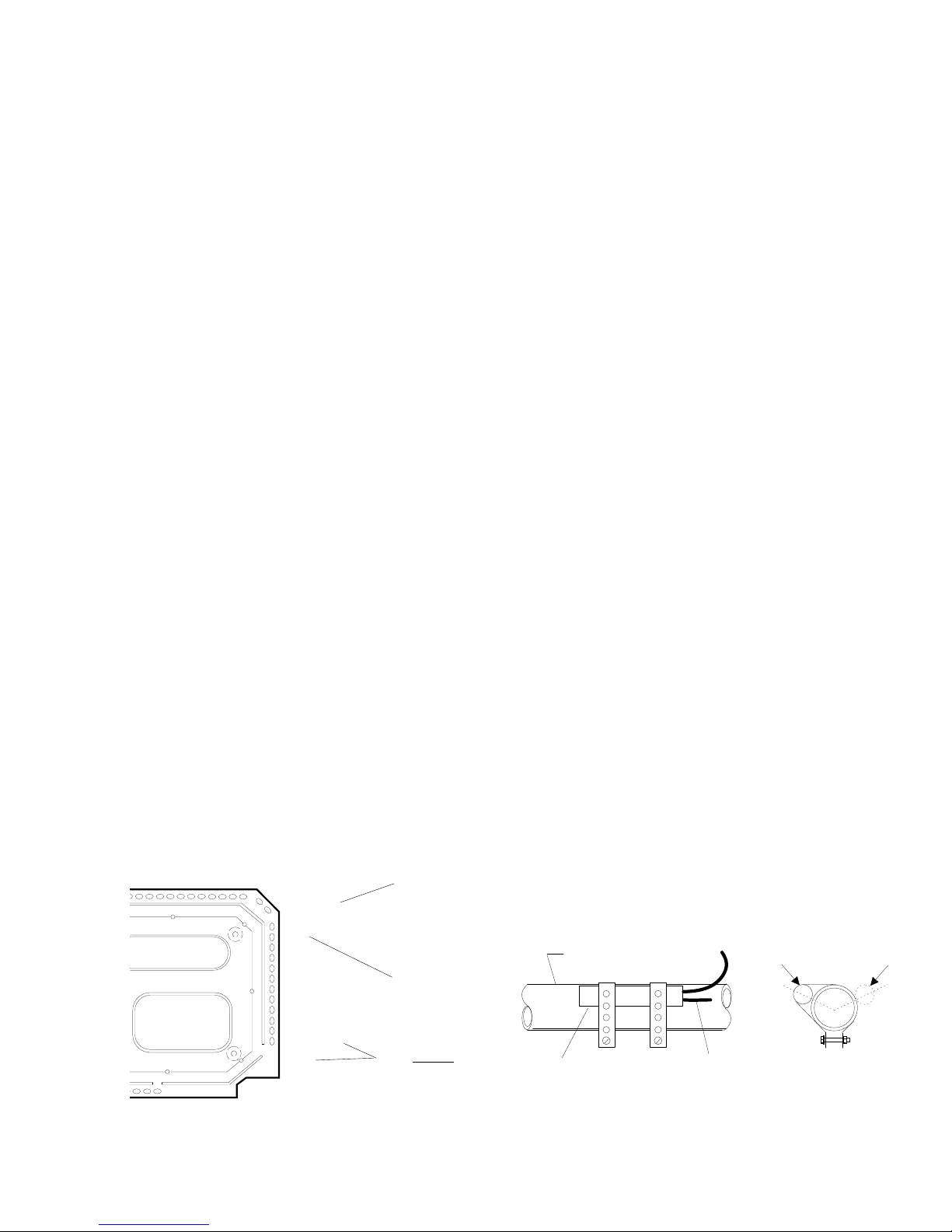
Secure using the clamps fur nis hed in th e kit. S ee Fig ure 3.
for positioning of the bulb. Insulate bulb after ins tallation.
FIGURE 2 - POSITIONING GROMMETS
Central Environmental Systems 3
RUBBER
ELEV ATING
GROMMETS
(4)
Note: Do Not block
drainage holes with
grommets.
7/8" VAPOR LINE
SENSING
BULB
ROTATE BULB TO KEEP
TAIL AT BOTTOM
10 O'CLOCK
FIGURE 3 - CORRECT BULB LO C ATIONS
OR
END VIEW
2 O'CLOCK
Page 4
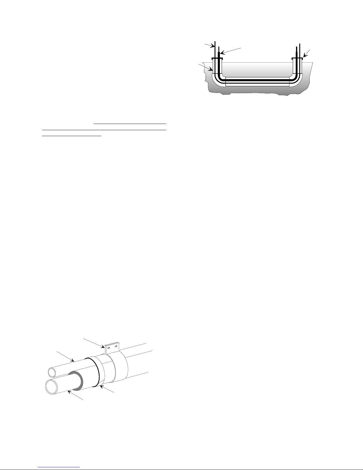
LIQUID
LINE
TAPE
SHEET
METAL
HANGER
INSULA T ED
VAPOR LIN E
TO INDOOR COIL
TO OUTDOOR UNIT
LIQUID LINE
CAP
PVC
CONDUIT
INSULATED
VAPOR LINE
550.37-N1Y
PIPING CONNECTIONS
The outdoor condensing unit may be connected to the indoor
evaporator coil using field supplied refrigerant grade copper
tubing that i s internally clean an d dry . Units should be ins talled
only with the tubing sizes for approved system combinations
as specified in Table 5. The charge g iven is appl icable f or total
tubing lengths up to 15 feet. See Application Data Form 690.01AD1V for installing tubing of longer lengths and elevation
differences.
NOTE: Using a larger than specified line size could result in
oil return problems. Us ing too small a line will result in
loss of capac ity and other p roblems caused by insu fficient refrigerant flow.
Slope horizontal vapor lines at
least 1" every 20 feet toward the outdoor unit to
facilitate pro per oil re tu rn.
PRECAUTIONS DURING LINE INSTALLATI ON
1. Install the lines with as few bends as possible. Care must
be taken not to damage the couplings or kink the tubing.
Use clean hard drawn copper tubing where no appreciable
amount of bending around obstruction is necessary. If soft
copper must be used, care must be taken to avoid sharp
bends which ma y caus e a rest ric tion.
2. The lines should be installed so that they will not obstruct
service acce ss to th e coil, air hand ling s yst em or filt er.
3. Care must also be taken to isolate the refrigerant lines to
minimize noise transmission from the equip ment to the structure.
4. The vapor line must be insulated with a minimum of 1/2"
foam rubber insulation (Arm-A-Flex or equivalent). Liquid
lines that will be exposed to direct sunlight and/or high
temperatures must als o be insulated.
5. Tape and suspend the refrigerant lines as s hown. DO NO T
allow metal-to met al cont ac t. See Figure 4.
6. Use PVC piping as a conduit for all underground installations as shown in Figure 5. Buried lines shoul d be kept as
short as possible to minimize the build up of liquid refrigerant in the vapor line durin g long p eriods of sh utdown.
FIGURE 5 - UNDERGROUND INSTALLATION
7. Pack fiber glass insulation and a sealing material such as
permagum around ref rigerant line s where they penet rate a
wall to reduce vi brat ion and t o retain s ome f lex ibili ty.
8. See Form 690.01-AD1V for additional piping information.
PRECAUTIONS DURING BRAZING OF LINES
All outdoor uni t and evaporat or coil c onnections are c opper-to-
copper and should be brazed with a phosphor ous-copper alloy
material such as Silfos-5 or equivalent. DO NOT use soft
solder.
CAUTION: Dry nitrogen should always be supplied through the
tubing while it is bein g brazed, because the temperature required is high enough t o cause oxidation of t he
copper unless an inert atmosphere is provided. The
flow of dry nitrogen should continue until the joint has
cooled. Always use a pressure regulator and safety
valve to insure tha t only low pressure dry nit rogen is
introduced into the tubing. Only a small flow is necessary to displace air and prevent oxidation.
The outdoor units have re-usable service valves on both the
liquid and vapor connections. The total system refrigerant
charge is retained within the outdoor unit during shipping and
installation. The re-usable service valves are provided to
evacuate and cha rge pe r thi s inst ruc t ion.
Serious service problems can be avoided by taking adequate
precautions to assure an internally clean and dry system.
PRECAUTIONS DURING BRAZING ANGL E VALVE
FIGURE 4 - TUBING HANGER
4 Central Environmental Systems
Precautions should be taken to prevent heat damage to angle
valve by wrapping a wet rag around it as shown in Figure 6.
Also, protect al l painted surfaces and in sulation during brazing.
After brazing - cool joint with wet rag.
WARNING: This is not a backseating v alve. The service access
port has a valve core. Opening or closing valve
does not close serv ice access p ort.
V alve can be opened by removing t he plunger cap (See Figure
7) and fully inserting a hex wrench into the stem and backing
out counter-clockwise until valve stem just touch es retaining ring.
Page 5

FIGURE 6 - HEAT PROTECTION
PLUNGER
CAP
CAUTION: If visual verific ation of the valv e stem reac hing the
retaining ring is impossible, stop backing out the
valve stem when the slightest increase in resistance is felt. Because of the small size and therefore the reduced resistance, back out the liquid
5 turns maximum
valve
retaining ring.
WARNING: If the valve stem is backed out past the retaining
ring, the O’ring can be damaged causing leakage
or system pressure could f orce the valve stem out
of the valve body pos s ibly c ausing p ersonal injur y.
In the event the retaining ring is missing, do not
attemp t t o op e n the valve .
Replace plunger cap f inger tight, then tigh ten an additional 1/12
turn (1/2 hex flat). Cap mus t be replac ed t o pre ven t leaks.
LINE CONNECTION
Connect the refrigerant lines using the fo llowing procedur e:
1. Remove the cap a nd Schrader core from both the liquid and
vapor angle valve serv ice ports at the outd oor unit. Connect
low pressure nitroge n to th e liqui d line serv ic e port .
2. Braze the liquid line to the liquid valve at the outdoor unit.
Be sure to wrap the valve body with a wet rag. Allow the
nitrogen to continue flowing.
3. Carefully remove the rubber plugs from the evaporator
liquid and vapor connectio ns.
to prevent going past the
ANGLE
VALVE
550.37-N1Y
CAUTION: The evaporator is pressuriz ed.
4. Braze the liquid line to the evaporato r liquid connectio n. The
nitrogen sho uld now be flowing throu gh the evaporator co il.
5. Slide the grommet away from the vapor connection at the
coil. Braze the vapor line to the evaporator vapor connection. After the connection has cooled, slide the grommet
back into origina l posit ion.
6. Protect the vapor v alve with a wet rag and braz e the vapor
line connection. The nitrogen flow should be exiting the
system from the vapor service port connection. After this
connection has cooled, remove the nitrogen source from
the liquid fitting servic e port .
7. Evacuate the vapor line, evaporator and the liquid line, to
1000 microns or les s .
8. Leak test all refrigerant piping connect ions including the se rvice port flare caps to be sure they are leak tight. DO NOT
OVERTIGHT EN (between 40 and 60 inch - lbs. maximum ).
NOTE: Do not use the system refrigerant in the outdoor unit
to purge or leak test.
9. Do not re mo ve t he f lare cap s from t he serv ice po rts excep t
when neces sa ry for s erv icing the system.
CAUTION: Do not connect manifold gauges unless trouble is
suspected. Approxi mately 3/4 oun ce of refrigeran t
will be lost each time a standard manifold gauge is
connec ted.
10.Release the refrigeran t charge into the s ystem. O pen both
the liquid and vapor valves by removing the plunger cap
and with an allen wrench back out counter-clockwise until
valve stem just touches retaining ring. See Figure 7. Release the refrigera nt charge into the syst em. See "Precautions During B raz ing Angle Valves" on page 4 and 5.
11. If the refrigerant tubing, indoor evaporator coil or outdoor
condensing unit ha s de veloped a leak du ring shipment , or
was, for any other reason, opened to the atmosphere for
more than four (4) minutes, it is necessary to e vacuate the
system down to at least 1000 mic rons to eliminate conta mination and mo istur e in the sy ste m.
If a leak is s uspec ted, lea k test to loc ate the leak . To verif y
the leak, close the valve to the vacuum pump suction to
isolate the pump and h old the system u nder v acuum. If the
micron gauge indicat es a steady and c ont inu ous rise after
a few minutes , it’s an indi cation of a leak . If the guage shows
a rise, then lev els of f aft er a few min ut es an d remains f ai rly
constant, its an indication that the sy stem is leak free, but
still contains moisture and may require further evacuation
if the reading is above 1000 mic rons .
FIGURE 7 - REM OVI NG PLUN GER CA P
Central Environmental Systems 5
WARNING: Never attempt to repair any brazed connections
while the syste m is under pressure. Personal injury
could result.
See "System Start Up" se ction for checkin g and recordin g
system charge.
Page 6

550.37-N1Y
ELECTRICAL CONNECTIONS
GENERAL INFORMATION & GROUNDING
Check the electrical su pply to be sure tha t it meets the values
specified on the unit namepl ate and wirin g label .
Power wiring, contro l (low voltage) wirin g, disconnec t switches
and overcurrent protection to be supp lied by the ins t aller. See
Table 1 for proper sizes. Wire size should be at least equal to
or greater than the s iz e shown in Table 1.
CAUTION: All field wiring must USE COPPER CONDUC-
TORS ONLY and be in accordance with Local,
National Fire, Safety & Electrical Codes. This
unit must be grounded with a separ ate ground
wire in accordance with the above codes.
The complete connection diagram and schematic wiring label
is located on the ins ide surface of the unit elec trical bo x cover.
Field wiring is also shown in Figure 1.
NOTE: The wires for the operatio n of the lead compressor are
solid in color. For differentiation, the wires of the follower compressor are basica lly t he sa me in color, but
striped.
POWER WIRING
1. Install the proper s ize weath erproof disconnect switc h outdoors and within sight of the un it.
THERMOSTAT MOUNTING / WIRING
This condens ing unit must be install ed with the factory re co m-
mended thermostat, 2ET04700224 or any conventional twostage cooling thermostat. The difference between the two
stages of a typical t wo-s ta ge t hermos t at is 2 - 2.5 °F.
The thermostat should be located about 5 ft. above the floor,
where it will be exposed to n ormal roo m air circ ulat ion . Do no t
place it on an outsid e wall or wh ere it is expos ed to the ra dian t
effect from exposed glass or appliances, drafts from outside
doors or supply air grilles.
After the th ermostat is mounted, rout e the 24-vo lt control wiring
(NEC Class 2) from the thermostat to the indoor v arible speed
air handler and outdoor unit. Route the control wirin g into the
grommetted hole in the bottom of control box of the outdoor
unit. Using wire nuts connect to leads provided in unit control
box as per Figure 8.
Interconnecting control wiring must be a minimum of No. 18
AWG color code d insulated wires. If wire lengt hs increase more
than 90 feet, use No. 16 AWG wires, to prevent excessive
voltage drop.
NOTE: T o eliminat e erratic operat ion, seal the hol e in the wall
at the thermostat with permagum or equivalent to
prevent air drafts affecting the anticipators in the
thermostat.
DE-HUMIDIFICA TION CONTROL
2. Run power wiring from the disconne ct swit ch to the unit .
3. Remove the control box cover to gain access to the unit
wiring. Route wires from disconnect through power wiring
opening provide d and into the unit control box a s shown in
Figure 8.
4. Install the proper size time-delay fuses or circuit breaker,
and make the power supply conne ction s.
5. Energize the crank c ase heat er to sa ve time by preheat ing
the compressor oil while the re ma ining instal lat ion is completed.
ACCESSORY WIRING
The electric al acces sories avai lable for thi s unit a re a two s tage
cooling thermostat and an optional De-humidification Control.
Refer to the individual instr uctions packaged with the accessories for installat io n.
A de-humidification control accessory 2HU06700124 may be
required in high humidity areas. This control provides cooling
at a reduced air flow, lowering evaporator temperature and
increasing la te nt cap acity. To install, re fer t o instructions pac kaged with the accessory. Prior to the installation of the de-humidification control, the jumper across the de-humidification
control terminals on the indoor variable speed air handler
terminal board must be removed. See Figure 10. Refer to
Figure 9 for wiring deta ils.
During first or second stage cooling, if the relative humidity in
the space is higher than the desired s et point of the de- humidification cont rol, the var iable speed blower motor will op erate at
a lower speed unti l the de-hu midif ication c ontro l is satis fied. A
40 - 60% relative humidity level is recommended to achieve
optimum comfort.
NOTE: If a de-humidification control is installed, it is recom-
mended that a minimum air flow of 325 cfm/ton be
supplied at all times .
6 Central Environmental Systems
Page 7

FIGURE 8 - TYPICAL FIELD WIRING
FIGURE 9 - T YPICAL FIELD WIRING WIT H
C
ALL FIEL D WIRING TO BE IN ACCORDANCE WITH N ATIONAL ELECTRICA L CODE (NEC) AND/OR LOCAL CODES.
R
Y2
Y1
G
W1
W2
TYPICAL
TWO STAGE
COOLING
THERMOSTAT
MUST BE
USED
INDOOR
VARIABLE SPEED AIR
HANDLER / FURNACE
TERMINAL BOARD
C
R
Y2
Y1
Y
G
W/W1
FOR ELECTRIC HEAT ONLY
W2
BK
X
O
WIRE NUT
BLU
RED
BRN
YEL
BLK
POWER
CONTROL
FACTORY
C
R
Y2
Y1
Y2 OUT
OUTDOOR UNIT
CONTACTOR
T2
T1
M2
L2
L1
(CLASS 1 WIRING)
(CLASS 2 WIRING)
CONTACTOR
T2
T1
M1
L2
L1
POWER WIRING
208/230-1-60
GRD.
SCREW
550.37-N1Y
COOLING
ONLY
C
R
Y2
Y1
G
W1
W2
TYPICAL
TWO STAGE
COOLING
THERMOSTAT
MUST BE
USED
All outdoor wiring must be
weatherproof. Use copper
conductors only .
INDOOR
VARIABLE SPEED AIR
HANDLER / FURN ACE
TERMINAL BOARD
C
R
Y2
Y1
Y
G
W/W1
W2
BK
X
O
DE-HUMIDIFICATION
CONTROL CONNECTION
(JUMPER MUST BE REMOVED)
POWER
CONTROL
FACTORY
CONTROL
WIRING
OUTDOOR UNIT
WIRE NUT
BLU
RED
BRN
YEL
BLK
FOR ELECTRIC HEAT ONLY
C
R
Y2
Y1
Y2 OUT
CONTACTOR
T2
T1
M2
L2
L1
(CLASS 1 WIRING)
(CLASS 2 WIRING)
CONTACTOR
T2
T1
M1
L2
L1
POWER WIRING
208/230-1-60
GRD.
SCREW
POWER
WIRING
COOLING
WITH
DE-HUMIDIFICATION
CONTROL
DE-HUMIDIFICATION CONTROL
Central Environmental Systems 7
Page 8

DELAY
PROFILE T AP
COOL TAP
ELECTRIC
HEA T TAP
ADJ TAP
ELECTRIC HEAT OR TRANSFORMER WIRING
HARNESS CONNECTS HERE
550.37-N1Y
TABLE 2 - RECOMMENDED SPEED TAP SELECTION
INDOOR
V A RIABLE
SPEED
AIR
HANDLER
N1VSD14
N2VSD20
SCREW
TERMINAL
BOARD
INDOOR
EVAP.
COIL
G/HC036
G/HC042
G/HC048
G/HC060
NOTE: For ARI testing requirements, adjust the delay profile in "Test Mode". Refer to Installation Instructions for N1VS variable speed
air handlers for additional details if necessary.
NA = N ot Applicable.
COOL
TAP
Jumper
at "B"
Jumper
at "A"
Jumper
at "A"
H*DS036 H*DS048 H*DS060
ADJ
TAP
NO
Jumper
NO
Jumper
Jumper
at "C"
DELAY
PROFILE
Jumper
at "C"
Jumper
at "C"
Jumper
at "C"
CONDENSING UNITS
COOL
TAP
NA NA NA NA NA NA
Jumper
at "B"
Jumper
at "C"
ADJ
TAP
NO
Jumper
NO
Jumper
DELAY
PROFILE
Jumper
at "C"
Jumper
at "C"
COOL
TAP
NA NA NA
Jumper
at "B"
ADJ
TAP
Jumper
at "C"
BLOWER MOTOR
INTERFACE HARNESS
CONNECTS HERE
JUMPER IN STORED POSITIO N
(Vertically on RH side, pins "A" and "B")
DELAY
PROFILE
Jumper
at "C"
DE-HUMIDIFI
CATION
CONTROL
ACCESSORY
JUMPER
HEAT PUMP JUMPER
FIGURE 10 - N1VS/N2VS Connector Board
SPEED TAP SELECTION FOR VARIABLE SPEED
AIR HANDLERS
The variable speed air handler motor’s speed tappings must
be adjusted from the factory settings for the required outdoor
condensing unit as shown in Table 2. A typical v ariable speed
air handler (N1VS/N2V S) connector board co nfiguration sho wing the various speed taps is shown in Figure 10. Refer to
variable speed air handl er installation inst ructions for additional
details, regarding the C FM for the c orre sponding speed taps.
JUMPER IN "A" CF M
(Horizontally jumper two "A" pins)
By selecting the speed taps shown in Table 2, the air handler
will deliver the rated CFM when both (lead and follower)
compressors are running, and the air handler motor will operate at a lower speed automatically when only the lead compressor is running. The variable speed motor used in this air
handler is programmed to automatically adjust to the lower
speed when there is a call for first stage (Y1) cooling from the
two stage cooling ther mo stat .
8 Central Environmental Systems
Page 9

LIQUID
PRESSURE
(PSIG) @
SERVICE
PORT
Required Subcooling Temp. ° F
LIQUID
PRESSURE
(PSIG) @
SERVICE
PORT
Required Subcooling Temp. ° F
5 10 12 15 20 5 10 12 15 20
Liquid Line Temperature ° F Liquid Line Temperature ° F
139 73 68 66 63 58 264 116 111 109 106 101
146 76 71 69 66 61 271 117 112 110 107 102
153 79 73 71 68 63 276 120 115 113 110 105
161 82 77 75 72 67 285 122 117 115 112 107
166 85 90 88 85 80 301 126 121 119 116 111
179 89 84 82 79 74 309 127 122 120 117 112
187 92 87 85 82 77 317 130 125 123 120 115
196 95 90 88 85 80 325 132 127 125 122 117
202 97 92 90 87 82 333 134 129 127 124 119
208 99 94 92 89 84 342 136 131 129 126 121
220 103 98 96 93 88 350 138 133 131 128 123
229 106 101 99 96 91 359 140 135 133 130 125
236 108 103 101 98 93 368 142 137 135 132 127
246 111 106 104 101 96 377 144 139 137 134 129
256 114 109 107 104 99 386 146 141 139 136 131
TABLE 4 - SUB-COOLING CHART
550.37-N1Y
SYSTEM START-UP
ENERGIZE CRANKCASE HEATER
This unit is equipped with crank ca se heat ers for both th e lead
and follower compressors. The operation of the crankcase
heater is monito red by means of the con tro l board .
CAUTION: An attempt to start the compressor without at least
8 hours of crankcase heat will damage the compressor.
A warning label with an adhesive back is supplied in the unit
installation in struction p acket. This label shoul d be attac hed to
the field su pplied disconnec t switch where it will be easily seen.
See below .
IMPORTANT
IF POWER HAS BEEN OFF FOR 8 HOURS OR LONGER,
DISCONNECT SWITCH MUST BE TURNED ON 8 HOURS
BEFORE THERMOS TAT IS SE T TO “HEAT”,"COOL" OR
“AUTO”
035-03095.
In order to energize the crankcas e heater:
- Set indoor two stage cooling ther mo stat to "OFF" pos ition .
- Close the line power disconne ct to the unit .
CHECKING SYSTEM CHARGE
The factory charge in the outdoor unit is listed in the Table 5 as
well as unit nameplat e and inclu des enough charge for th e unit
and the corresponding indoor evaporator coil. This unit includes suffic ient charge for 15 feet of line set s. T ab le 6 lists the
refrigerant line ch arges for addi ti onal le ngt hs .
CAUTION:
REFRIGERANT CHARGING SHOULD ONLY BE
CARRIED OUT BY A QUALIFIED AIR CONDITIONING CONTRACTOR.
In order to check whether the unit has the required charge in
the system, follow t he proc edur e des cri bed be l ow.
WARNING:DO NOT VENT REFRIGERANT TO THE ATMOS-
PHERE. IT IS NECESSARY TO RECOVER THE
REFRIGERANT DURING ANY REPAIR OR INST ALLATION OF THE SYSTEM.
1. Set room thermostat at desired temperature. The thermostat may be energized at first (Y1) stage or second (Y2)
stage. If only the first stage (Y1) is energiz ed, only the lead
compressor will be in operat ion. Both the compress ors will
be in operation if the second stage of thermostat (Y2) is
energized.
Set room therm ostat at "COOL" position and fan switch at
"AUTO" or "FAN" position. There is a five minute delay
when the "system control board" is powered for the first
time. Refer to "System Functions" for more information
about time delays.
2. Operate the unit for a minimum of 15-20 minutes before
checki n g th e ch a rg e .
3. Ve rif y the de sire d indo or air han dler ai r flo w (CFM).
4. The system charge should be varified with only the lead
compressor running, however it can be also checked with
both the compressors running at t he same time at the rat ed
indoor air handle r air flow. However, it is required to es tablish the subcoolin g level at any one condition i.e. either with
the lead compressor running or when both (the lead and
follower) compressors are running.Recommended subcooling temperat ure is listed in Table 3.
TABLE 3 - RECOMMENDED SUBCO OLING
RECOMMENDED SUBCOOLING °F
MODEL
H1DS036 10 18
H1DS048 10 18
H1DS060 10 18
*Lead compressor is designated / labeled as the # 1 compressor. Follower compressor is the # 2 compressor.
LEAD
COMPRESSOR
ONLY
LEAD + FOLLOWER*
(BOTH)
COMPR. RUNNING
Central Environmental Systems 9
Page 10

550.37-N1Y
5. Measure li quid ref rige rant p res su re a t th e service valve by
attaching an accurate pressure gauge to the service port
and record the pressure.
NOTE: When only the lead compressor is running, the
suction pressure will be higher than a standard
single speed system, or a dual compressor system with both compressors running. This is a
normal operation for a dual compressor system
operating with a large indoor coil at part load
capacities.
6. Refer to the Table 3 to find the recommended subcooling
temperature.
7. Refer to Table 4 to deter mine the proper l iquid line temperature at the point where the "Required Subc ooling Temperature" and "Measured Liquid Pressure"(from step 5)
intersect. Record t he requ ired li quid li ne t emperat ur e.
8. Measure the liquid line temperature by attaching an accurate electro nic thermomete r or a thermistor at the liquid line
near the cond ens ing un it.
9. If the liquid line temperatu re is higher th an the valu e determined in step 7, add refrigerant charge carefully until the
recommended subcooling temperature is obtained at the
correspondi ng liqu id line pres sure.
CAUTION: DO NOT OVERCHARGE THE SYSTEM,
THIS COULD LEAD TO DAMAGE TO THE
COMPRESS ORS.
It is suggested to maintain the recommended subcooling
levels indica ted in Table 4, wit hin ±2 °F . Too low a subc ooling or too high a subc ooling will re sult in poo r performan ce
of the air condit ion ing unit.
NOTE: If liquid line temperature is lower, remove and
recover the refrige rant charge unt il the reco mmended subcooling temperat ure is obt aine d.
EXAMPLE:
Given an H1DS036 with only the lead compressor operating
on first stage.
1. Liquid pressure at t he service valve = 179 lbs.
2. Recommended subc ool ing t empera tu re f rom Table 3.
= 10 °F
3. Required liquid line temperat ure from Table 4 = 84 °F
If the measured liquid line temperature at the liquid line near
the condens ing un it = 89 °F, then the actual level of subc ooling
based on Table 4 = 5° F
Therefore, add charge to reach required liquid line temperature given in Step 3, thereby, reaching the recommended
subcooling lev el in St ep 2 abov e.
If the measured liquid line temperature at the liquid line near
the condensing uni t = 79 °F, then the actual level of subc ooling
based on Table 4 = 15 °F.
Therefore, remove and re cover charge t o reach required li quid
line temperature given in Step 3, thereb y , reaching the recommended subcooling level in Step 2.
Once the charge is established when the lead compressor is
running, it is not neces sary to establish the ch arge once again
when both compressors are running. However it is recommended to energize the second compressor to verify system
performance.
TABLE 6 - REFRIGERANT LINE CHARGES
UNIT
SIZE
036, 048, 060 3/8 7/8 0.70
LIQUID LINE OD
VAPOR
LINE OD
R22 CHARGE
OZ / FT
TABLE 5 - CHARGE ADD STANDARD COILS
APPROVED SYSTEM COMBINATIONS
(Outdoor Unit / Variable Speed Air Handler & Coil)
H1DS036
N1VSD14
N2VSD20
H1DS048 N2VSD20
H1DS060 N2VSD20 G3HC / G1FC060 14 - 6 +0
10 Central Environmental Systems
G3HC / G1FC036
G3HC / G1FC042 +0
G3HC / G1FC048 +0
G3HC / G1FC060 +14
G3HC / G1FC048
G3HC / G1FC060 +14
CONDENSING UNIT
FACTORY CHARGE
LBS. - OZ.
9 - 9
9 - 9
INDOOR COIL
ADJUSTMENT
CHARGE, OZ.
+0
+0
Page 11

550.37-N1Y
RECORDING TOTAL SYSTEM CHARGE
The factory charge in the outdoor unit is listed in Table 5 and
includes enough charge for the unit, matched evaporator and
15 feet of lines. In stallations over 15 feet lo ng and some indoor
coil matches may require some addition al charge. Table 6 lists
the refrigeran t line charges .
The “TOTAL SYSTEM CHARGE” must be permanently
stamped on the unit dat a plat e.
Total system charge is determined as follows:
1. Determine t he c onde nsi ng unit c harge from Table 5.
2. Determine indo or coil adjustment charge fro m Table 5.
3. Calculat e the additional ch arge for line lengths greater than
15 feet using Table 6 factors.
4. Total system charge = Item 1 + Item 2 + Item 3.
5. Permanently stamp the unit da ta plate with the total amount
of refrigerant in the system.
SYSTEMS FUNCTIO NS
The dual compress or Stellar UL TRA air con ditioner has un ique
system functions as described below.
erations. See Table 7, which provides a list of LED functions
and definitio ns.
Power Supply
The five minute control board time delay is energized by means
of 24V power supply from th e transformer installed in the indoor
variable speed air handler. As soon as the control board
receives power, it warms up for five minutes before it starts
operating. The control boar d also has a 3A fuse which protects
the control board f rom sh ort circuit ing.
Five Minute Time Delay (Control Board)
Every time the con trol board is po wered afte r a power interruption, it will delay the operation f or fiv e minute s . Th e LED ligh t
on the control board wil l blink "ON" for 1 second and "OFF" f or
4 seconds, indicating a warm up period for the control board.
This will prevent the un it from short cyc ling.
Five Second Time Delay
A five second time delay is energized every time the board
receives a control signal Y1 or Y2 from the thermostat. This
prevents cycling of the unit and unnecessary operation of the
unit as a result of thermostat jigglin g.
One Minute Inter Stage Time Delay
COOLING OPERATION
The condensing unit utilize s a two stage cooling indoor thermostat. Depending on the cooling load requirements, the compressors are energized in sequence by means of the two stage
thermostat.
With a call for first stage cooling (Y1), the out door fan and the
lead compressor are energized. Simultaneously, the variable
speed indoor blower motor is also energized and the blower
delivers the corresponding airflow adequate for the first stage
cooling load.
With a call for second stage cooling (Y2), the follower compressor is also energized. Simultaneously, the variable speed
blower now delivers the rated CFM in order to satisfy the
cooling demand. The follower compressor is energized only
when cooling demand is not met by the lead compressor
running alone. Once t he second stage building load is satisfied,
the unit will operate with only the lead compressor, until first
stage indoor c ooling the rmostat is sati sfied, o r if t here is a call
for second stage c oolin g oper ation.
SYSTEM CONTROL BOARD OPERATIONS
The Stellar ULTRA air conditioner utilizes a control board to
control as well as monitor the operatio n of the two stage cooling
system. The following is an overview of the functions of the
control board.
Control Board LED Fun ctio ns
The control board used t o contro l and mon itor the op erat ion of
the two stage cooling sys tem has a LED mounted on the board,
which provides signals (Fault Codes) for several system op-
Anytime the unit receives a call for second stage cooling
operation (Y2) from t he thermostat, when the lead compressor
is operating, there is a one minute time delay before the
follower compressor will start. The outdoor fan motor and the
lead compressor continue to run during this inter-stage time
delay.
Five Minute Time Delay (Co m pr es so r 1 an d 2)
A five mi nute t ime delay p revents the system from short cyc ling
after a thermostat of f cyc le or po we r int errup ti on.
There is a five minute time delay for both, the lead and the
follower compres sor after a the rmostat of f cycle. These delay s
are incorporated to prevent the short cycling of the unit. However , during t he fi ve minute de lay on the follower c ompres sor,
the lead compressor and the outdoor fan will continue to run,
together with the indoor variable speed air handler, if the call
for cooling still exists.
For servicing or during ins tallation of the condensing unit, t he time
delay may be overridden by momentarily jumpering the test
terminal and "R" terminal on the board if necessa ry . However ,
the jumper must be removed during no r mal opera ti on.
Pressure Switches
High and low pressure switches are installed and wired in
series. They p rovide addtional protection for the system if any
abnormal operating conditions occur. If the control board
senses a tripping of the high or low pressure switch, the control
will provide a five minute delay before the system starts operating again. The LED will blink rapidly indic ating that there is a
Central Environmental Systems 11
Page 12

550.37-N1Y
TABLE 7 - LED FUNCTIONS
LED DISPLAY DEFINITION
LED LIGHT "ON" (No Flashing) Normal Operation
FLASH (1 Second) PAUSE (4 Seconds) Control Board Warm-up Operation
FLASH (1 Second) PAUSE (1 Second) High or Low Pressure Switch Trip
RAPID FLASHES High or Low Pressure Switch Lockout
LED LIGHT "OFF" No Power Supply or Board Failure
system error. The LED will blink "ON" for 1 sec ond an d "O FF"
for 1 second during the opening of either h igh o r low pre ssure
switches. If four t rips occur within 30 minut es, the control b oard
logic will lock out the outdoor unit, preventing operation. The
unit can be operated again by resetting the indoor two stage
cooling thermost at once the loc kou t cond it ion is reso lv ed.
Crankcase Heater Operation
The control board will energize the cra nkcase heater during the
condensing unit "OFF" cy cle.
Condensin g Unit Fan Ope r atio n
The control board will ene rgize the condensing unit fan a nytime
the compressor is operati ng. The outdoor fan will remain energized during the "One Minute Inter-Stage Time Delay". However , the fan will not remain energized, if either , the High or Lo w
pressure switch es trip.
INSTRUCTING THE OWNER
Assist owner with processing warr ant y ca rds . Revi ew Owne rs
Guide and provide a copy for the owner guidance on proper
operation and main tenanc e. Inst ruct the o wner or the o perator
how to start, stop and adjust temperature setti ng.
1. The outdoor fan should be running, with warm air being
discharged from t he top of the unit .
2. The indoor blower (furnace or air handler) will be operat ing,
discharging cool air from the ducts.
3. The vapor line at the outdoor unit will feel cool to the touch.
4. The liquid line at the outdoo r unit will feel warm to the to uch.
If unit is not operating p roperly , check the follo wing items bef ore
calling a servic eman :
1. Indoor section for dir ty filt er.
2. Outdoor sect io n for leaf or debr is block ag e.
Eliminate problem, turn off the thermostat for 10 seconds and
attempt start. Wait 5 minutes. If system does not start, call
service technician.
MAINTENANCE
1. Dirt should not be allowed to accumulate on the outdoor
coils or other parts in the air circuit. Clean as often as
necessary to keep the unit clean. Use a brush, vacuum
cleaner attac hment , or ot her suit able mea ns.
When applicable, instruct the owner that the compressor is
equipped with a crankcase heater to prevent the migration of
refrigerant to the compressor during the “OFF” cycle. The
heater is energized only when the uni t is not running. If the main
switch is disconnected for long periods of shut down, do not
attempt to start the unit 8 hours after the switch has been
connected. This will allow suf ficient time for all liquid refrigerant
to be driven out of the compressor .
The installer should also instruct the owner on proper operation and maintena nc e of all other s ystem compo nents.
INDICATIONS OF PROPER OPERATION
Cooling operation is the same as any conventional air conditioning unit.
The following checks may be made to determine if the system
is operating properly:
2. The outdo or fan moto r is permanently lubricated and does
not require periodic oiling.
3. If the coil needs to be cleaned, it should be washed with
Calgon CalClean (mix one part CalClean to seven parts
water). Allow solution to remain on coil for 30 minutes
before rinsing with clean water. Solution should not be
permitted to come in contact with painted surfaces.
4. Refer to th e furnac e or air han dler ins truc tio ns f or filt er and
blower motor maintena nc e.
5. The evaporator coil drain pan should be inspected and
cleaned regula rly to prevent odors and assure proper drainage.
WHEN THE SYSTEM IS FUNCTIONING PROPERLY AND
THE OWNER HAS BEEN FULLY INSTRUCTED, SECURE
THE OWNER’S APPROV AL.
P.O. Box 1592, York, Pennsylvania USA 17405-1592
Subject to change wi thout notice. Printed in U.S.A
Copyright by York International Corporation 1994. All Rights Reserved.
 Loading...