

Page 1
INSTALLATION
INSTRUCTION
CONTENTS
GENERAL . . . . . . . . . . . . . . . . . . . . . . . . . . . . . . . . . . . . . . . . . . . 2
N
OMENCLATURE
P
RODUCT CATEGORY
P
RODUCT GENERATION
P
RODUCT IDENTIFIER
N
OMINAL COOLING CAPACITY
R
EFRIGERANT LINE CONNECTIONS
V
OLTAGE CODE
SAFETY . . . . . . . . . . . . . . . . . . . . . . . . . . . . . . . . . . . . . . . . . . . . . 2
INSPECTION . . . . . . . . . . . . . . . . . . . . . . . . . . . . . . . . . . . . . . . . . 2
LIMITATIONS. . . . . . . . . . . . . . . . . . . . . . . . . . . . . . . . . . . . . . . . . 2
UNIT INSTALLATION . . . . . . . . . . . . . . . . . . . . . . . . . . . . . . . . . . 3
LOCATION . . . . . . . . . . . . . . . . . . . . . . . . . . . . . . . . . . . . . . . . . 3
GROUND INSTALLATION . . . . . . . . . . . . . . . . . . . . . . . . . . . . . 3
ROOF INSTALLATION . . . . . . . . . . . . . . . . . . . . . . . . . . . . . . . . 3
UNIT PLACEMENT . . . . . . . . . . . . . . . . . . . . . . . . . . . . . . . . . . . 3
DISCHARGE LINE FILTER-DRIER . . . . . . . . . . . . . . . . . . . . . . 4
PIPING CONNECTIONS . . . . . . . . . . . . . . . . . . . . . . . . . . . . . . 4
PRECAUTIONS DURING LINE INSTALLA TION . . . . . . . . . . . . 4
PRECAUTIONS DURING BRAZING OF LINES . . . . . . . . . . . . 5
PRECAUTIONS DURING BRAZING ANGLE VALV E . . . . . . . . 5
ORIFICE SELECTION . . . . . . . . . . . . . . . . . . . . . . . . . . . . . . . . . . 7
ELECTRICAL CONNECTIONS . . . . . . . . . . . . . . . . . . . . . . . . . . . 7
GENERAL INFORMATION & GROUNDING . . . . . . . . . . . . . . . 7
POWER WIRING . . . . . . . . . . . . . . . . . . . . . . . . . . . . . . . . . . . . 7
ACCESSORY WIRING . . . . . . . . . . . . . . . . . . . . . . . . . . . . . . . . 7
THERMOSTAT MOUNTING / WIRING . . . . . . . . . . . . . . . . . . . 7
EVACUATION . . . . . . . . . . . . . . . . . . . . . . . . . . . . . . . . . . . . . . . . 9
SYSTEM CHARGE . . . . . . . . . . . . . . . . . . . . . . . . . . . . . . . . . . . . 9
REFRIGERANT LINE CHARGES . . . . . . . . . . . . . . . . . . . . . . . . . 9
M
EASUREMENT METHOD
S
UPERHEAT CHARGING METHOD
SYSTEM START-UP . . . . . . . . . . . . . . . . . . . . . . . . . . . . . . . . . . 10
ENERGIZE CRANKCASE HEATER . . . . . . . . . . . . . . . . . . . . .10
SYSTEM OPERATION. . . . . . . . . . . . . . . . . . . . . . . . . . . . . . . . . 10
SEQUENCE OF OPERATION COOLING: . . . . . . . . . . . . . . . . . 10
HEATING: . . . . . . . . . . . . . . . . . . . . . . . . . . . . . . . . . . . . . . . . . 10
EMERGENCY HEAT: . . . . . . . . . . . . . . . . . . . . . . . . . . . . . . . . 11
DEFROST: . . . . . . . . . . . . . . . . . . . . . . . . . . . . . . . . . . . . . . . . 11
TEST PIN: . . . . . . . . . . . . . . . . . . . . . . . . . . . . . . . . . . . . . . . . . 11
INSTRUCTING THE OWNER . . . . . . . . . . . . . . . . . . . . . . . . . . . 12
INDICATIONS OF PROPER OPERATION . . . . . . . . . . . . . . . . . 12
COOLING . . . . . . . . . . . . . . . . . . . . . . . . . . . . . . . . . . . . . . . . . 12
HEATING. . . . . . . . . . . . . . . . . . . . . . . . . . . . . . . . . . . . . . . . . 13
MAINTENANCE . . . . . . . . . . . . . . . . . . . . . . . . . . . . . . . . . . . . 13
. . . . . . . . . . . . . . . . . . . . . . . . . . . . . . . . . . . . . . 2
. . . . . . . . . . . . . . . . . . . . . . . . . . . . . . . . . . 2
. . . . . . . . . . . . . . . . . . . . . . . . . . . . . . . . . 2
. . . . . . . . . . . . . . . . . . . . . . . . . . . . . . . . . . 2
. . . . . . . . . . . . . . . . . . . . . . . . . . . . 2
. . . . . . . . . . . . . . . . . . . . . . . . 2
. . . . . . . . . . . . . . . . . . . . . . . . . . . . . . . . . . . . . . 2
. . . . . . . . . . . . . . . . . . . . . . . . . . . . . . . . 9
. . . . . . . . . . . . . . . . . . . . . . . . .10
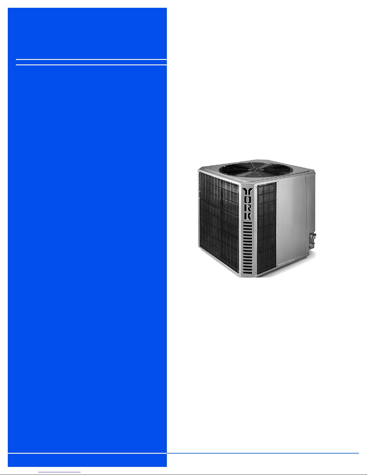
STELLAR
OUTDOOR
SPLIT-SYSTEM HEAT PUMP
MODELS: 10 SEER
1 PH 208/230 V E4FD018 - 60
3 PH 208/230 V E4FD036 - 60
3 PH 460 V E4FD036 - 60
CAUTION:READ ALL SAFETY GUIDES BEFORE
YOU BEGIN TO INSTALL YOUR UNIT.
SAVE THIS MANUAL
035-17421-000 REV B (700)
Page 2
GENERAL
The outdoor units are designed to be connected to a matching indoor coil with sweat connect lines. Sweat connect units
are factory charged wi th refrige rant f or a match ing indo or coil
plus 15 feet of field supplied lines.
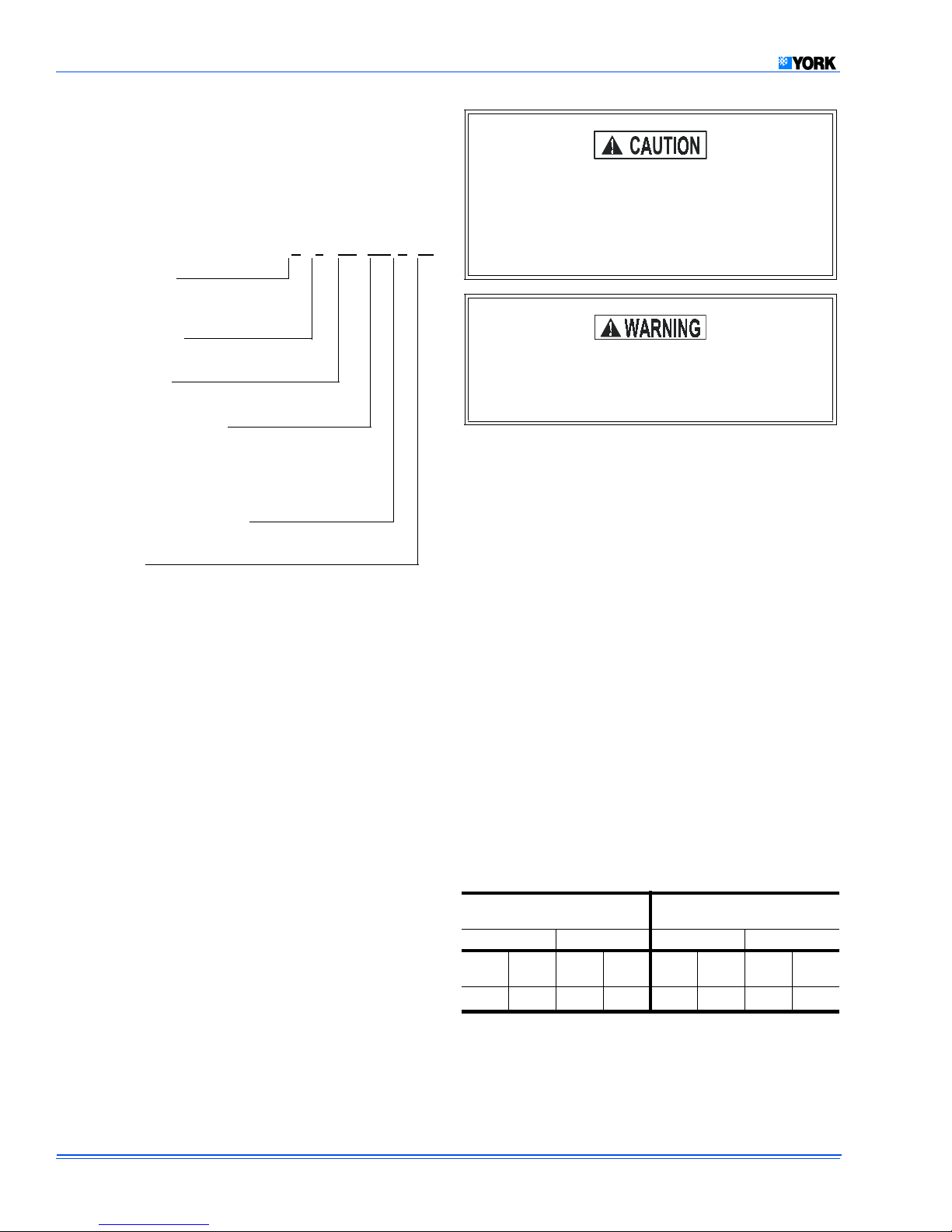
NOMENCLATURE
E 4 FD 030 S 06
Product Category
E = Outdoor Split System
Heat Pump
Product Generation
4 = Design Level
Product Identifier
FD = 10 SEER Heat Pump (60 Hz)
Nominal Cooling Capacity
018 = 1.5 Tons 042 = 3.5 Tons
024 = 2 Tons 048 = 4 Tons
030 = 2.5 Tons 060 = 5 Tons
036 = 3 Tons
Refrigerant Line Connections
S = Sweat-Fittings
Voltage Code
06 = 208/230-1-60
25 = 208/230-3-60
46 = 460-3-60
Matching indoor coils are avai lab le with a therm al exp an sio n
valve or an orifice liquid feed (YORKMATE flow control
device) sized for the most common usage. The orifice size
and/or refrigerant charge may need to be changed for some
indoor-outdoor unit combinations, elevation differences or
total line lengths. R efer to Ap plication D ata coverin g “General
Piping Recommendations and Refrigerant Line Length”
(Form 690.01-AD1V).
SAFETY
Use this instruction in conjunction with the instruction for the
appropriate indoor e vapora tor co il, v ariabl e spe ed ai r hand ler
or furnace and othe r accessorie s. Read al l instruction s before
installing the unit.
Installer should pay particular attention to the words: NOTE,
CAUTION and WARNING.
NOTES are intended to clarify or ma ke the inst allation easier.
CAUTIONS are given to prevent equipment damage.
WARNINGS are given to alert the installer that personal
injury and/or equipment dam ag e may resu lt if ins ta lla tion procedures are not handled properly.
This product must b e installed in strict co mpliance
with the enclosed installation instructions and any
applicable loca l, stat, and nati onal c odes i nclud ing ,
but not limited to, bui lding, electrical and mechanica l
codes.
Incorrect installat ion may create a co ndition where the
operation of the product could cause personal injury
or property damage.
INSPECTION
As soon as a unit i s rece ived, it should be inspe cted for po ssible damage during tran si t. If da ma ge i s ev ide nt, the ex tent of
the damage should be n oted on the carrier’s delivery rec eip t.
A separate request for inspection by the carrier’s agent
should be made in writing. See Local Distributor for more
information.
LIMITATIONS
The unit should be installed in accordance with all national
and local safety codes and the limitations listed below:
1. Limitations for the indoor unit, coil and appropriate
accessories must also be observed.
2. The outdoor unit must not be insta lled w ith any du ct wor k
in the air stream. The outdoor fan is the propeller type
and is not designed to operate against any additional
external static pressure.
3. The maximum and minimum conditions for operation
must be observed to assure a system that will give maxi-
mum performance with minimum service.
Table 1: Application Limitations
AIR TEMPERATURE °DB ON
OUTDOOR COIL
Min. Max. Min. Max.
Cool Heat Cool Heat
*
50
-10
*.
Below -10°F, the unit operates automatically with resistance
heat only.
†.
Operation below this temperature is permissible for a short
period of time, during morning warm-up.
115 75 57
AIR TEMPERATURE ON
INDOOR COIL
WB
°
Cool
DB
°
Heat
50
†
WB
°
Cool
72 80
DB
°
Heat
2 Unitary Products Group
Page 3
035-17421-000 Rev B (700)
TO
BLOWER
MOTOR
RELAY
THERMOST AT
TO POWER
SUPPLY
NEC CLASS 1
WIRING
NEC CLASS 2
WIRING
TO
COIL
NOTE: ALL OUTDOOR WIRING
MUST BE WEATHERPROOF
SEAL OPENING(S) WITH PERMAGUM OR EQUIVALENT
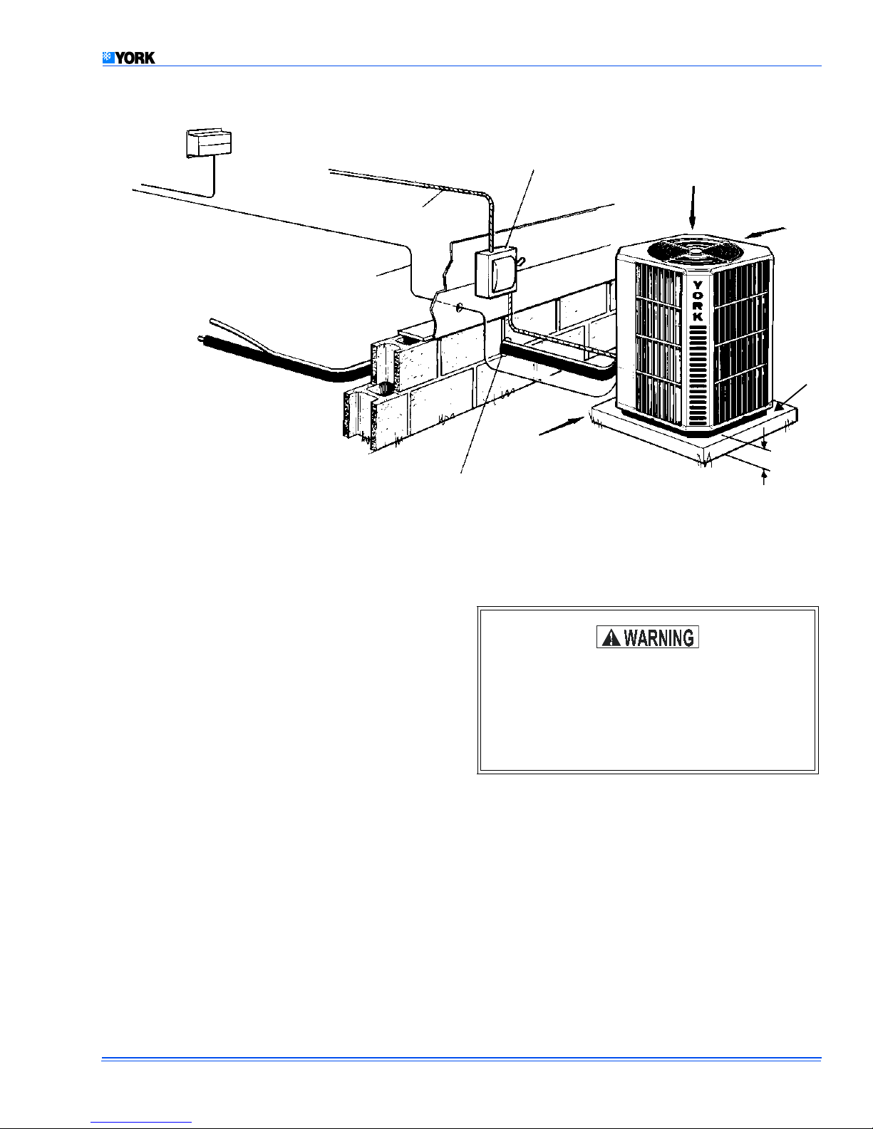
FIGURE 1: TYPICAL INSTALLATION
WEATHERPROOF
DISCONNECT
SWITCH
24” SERVICE
ACCESS CLEARANCE
REQUIRED
48” OVERHEAD
CLEARANCE
REQUIRED
12” REAR
AND SIDES
CLEARANCE
REQUIRED
Sit unit on
rubber
elevator
grommets
to reduce
noise and
allow for
proper
drainage.
UNIT INSTALLATION
LOCATION
Before starting the i nstallation, select and che ck the suitabi lity
of the location for both the indoor and outdoor unit. Observe
all limitations and clearance requirements.
The outdoor unit must have sufficient clearance for air
entrance to the condenser coil, for air discharge and for service access. See Figure 1.
If the unit is to be installed on a hot sun exposed roof or a
black-topped ground area, the unit should be raised sufficiently above the roof or ground to avoid taking the accumulated layer of hot air into the outdoor unit.
Provide an adequate structural support.
GROUND INSTALLATION
The unit may be insta lle d at ground level on a sol id b as e th at
will not shift or settle, causing strain on the refrigerant lines
and possible leaks. Maintain the clearances shown in Figure
1 and install the unit in a level position. Isolate the base from
the structure to avoid noise or vibration transmission.
Isolate the unit from rain gutters to avoid any possible wash
out of the foundation.
Normal operating sound levels may be objectionable if the
unit is placed directly under windows of certain rooms (bedrooms, study, etc.).
Condensate will drain from beneath the coil of the outdoor
unit during the defrost cycle. Normally this condensate may
be allowed to drain directly on the ground.
The outdoor unit should not be installed in an area
where mud or ice could cause personal injury.
Remember that cond ensate will drip from the unit co ils
during heat and defrost cycles and that this condensate will freeze when the temperature of the outdoor
air is below 32*F.
Elevate the unit su f f i ciently to prevent any blo ckage of the air
entrances by snow in areas where there will be snow accumulation. Check the local weather bureau for the expected
snow accumulation in your area.
ROOF INSTALLATION
When installing uni ts on a ro of, the struct ure m ust b e ca pab le
of supporting the total weight of the unit, including a pad, lintels, rails, etc., which should be used to minimize the transmission of sound or vibration into the conditioned space.
UNIT PLACEMENT
1. Provide a base in the pre-determined location.
Unitary Products Group 3
Page 4
2. Remove the shipping carton and inspect for possible
damage.
3. Compressor tie-down bolts should remain tightened.
4. Position the unit on the base provided.
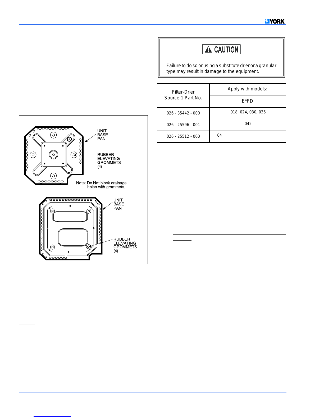
5. Sit unit on the (4) rubber elevating grommets provided
with the unit. These should be positioned as shown in
Figure 2
to reduce noise and allow for proper drainage.
6. Make a hole(s) in the structure wall large enough to
accommodate the insul ated va por li ne, the liqu id line and
the wiring.
UNIT
BASE
PAN
RUBBER
ELEVATING
GROMMETS
(4)
Note:DoNotblockdrainage
holeswithgrommets.
UNIT
BASE
PAN
RUBBER
ELEVATING
GROMMETS
(4)
FIGURE 2 : POSITIONING GROMMETS
DISCHARGE LINE FILTER-DRIER
The E*FD 018 - 042 heat pumps have a solid core filter-drier
located in the discharge line. Due to its location in the refrigerant circuit it requires a unique oversize ca pacit y drier . E*FD
048 and 060 have a solid core bi-flow filter/d ryer on the liq uid
line.
NOTE:
exact same as marked on the original factory drier. See
Source 1 for O.E.M. replacement driers.
Replacement of the discharge line drier must be the
Failure to do so or using a substit ute drier or a granular
type may result in damag e t o the e quipm ent.
Filter-Drier
Source 1 Part No.
026 - 35442 - 000
026 - 25596 - 001
026 - 25512 - 000
Apply with models:
E*FD
018, 024, 030, 036
042
048, 060 (Bi-flow on Liquid Line)
PIPING CONNECTIONS
The outdoor condensi ng unit m ay be conne cte d to the ind oor
evaporator coil using field supplied refrigerant grade copper
tubing that is internally clean and dry. Units should be
installed only with the tubing sizes for approved system combinations as specified in Tabular Data Sheet. The charge
given is applicable for total tubing lengths up to 15 feet. See
Application Data Form 690.01-AD1V for installing tubing of
longer lengths and elevation differences.
Using a larger than specifie d line size could result in oi l
NOTE:
return problems. Usin g too small a line will result in l oss
of capacity and other problems caused by insufficient
refrigerant flow . Slope horizontal vapo r lines at least 1 "
every 20 feet toward the outdoor unit to facilita te proper
oil return.
PRECAUTIONS DURING LINE INSTALLATION
1. Install the lines with as few be nds as poss ible. Care mus t
be taken not to damage the couplings or kink the tubing.
Use clean hard drawn copper tubing where no appreciable amount of bending around obstruction is necessary.
If soft copper must be used, care must be taken to avoid
sharp bends which may cause a restriction.
2. The lines should be insta lle d so that th ey will no t obstruc t
service access to the coil, air handling system or filter.
3. Care must also be taken to isolate the refrigerant lines to
minimize noise transmission from the equipment to the
structure.
4. The vapor line must be insulated with a minimum of 1/2"
foam rubber insulati on (Arm-A-F lex o r eq uiv al ent). Li qui d
lines that will be exposed to direct sunlight and/or high
temperatures must also be insulated.
4 Unitary Products Group
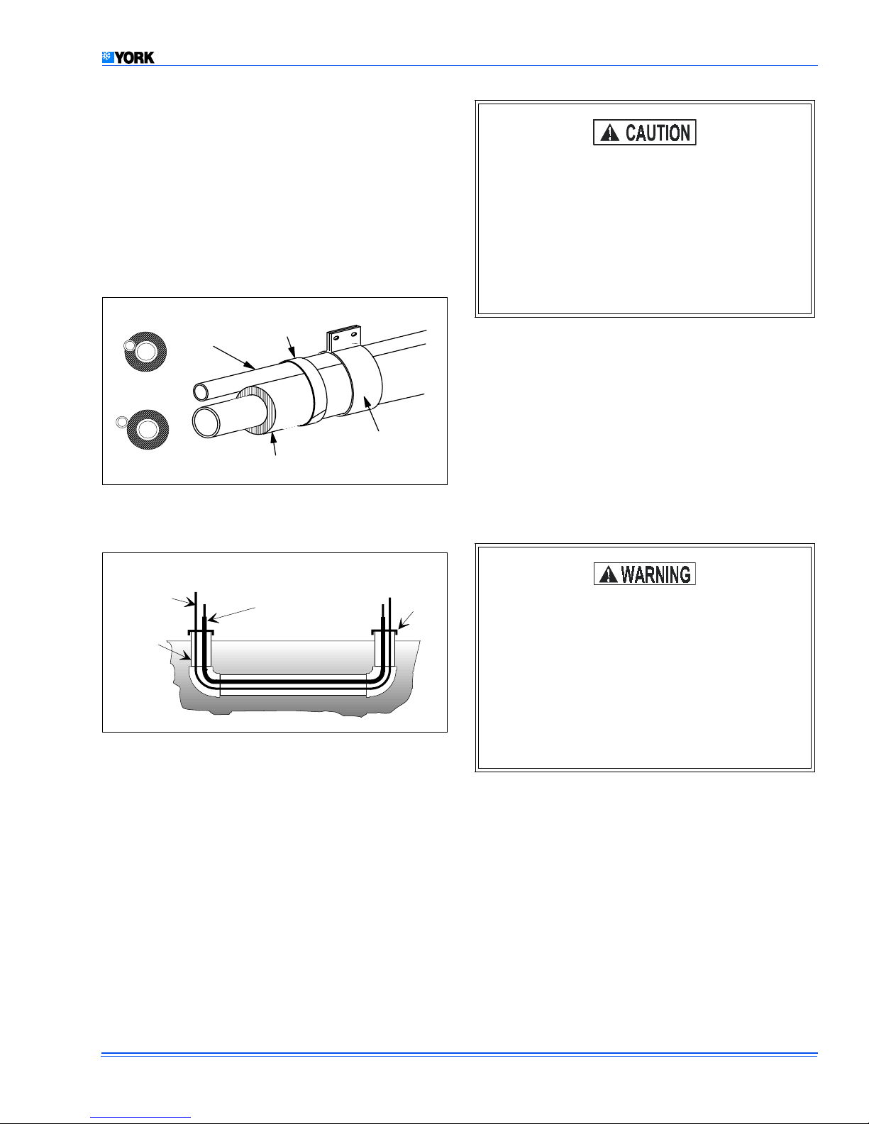
Tape and suspend the refrigerant lines as shown. DO NOT
allow metal-to metal contact. See Figure 3.
Page 5
5. Total line le ng ths ar e li mi ted to 75 fe et due to the storage
capacity of the accumulator. Systems with total line
lengths over 50 feet must be provided with a low voltage
start kit. Elevation differences are limited to:
Indoor Above Outdoor 50 ft.
Outdoor Above Indoor 50 ft.
6. Use PVC piping as a cond uit for all underground inst all ations as shown in Figure 4. Buried lines should be kept
as short as possible to minimize the build up of liquid
refrigerant in the vapor line during long periods of shutdown.
035-17421-000 Rev B (700)
Dry nitrogen should always be supplied through the
tubing while it is bei ng brazed, b ecause the temper ature required is high eno ugh to cause oxi dation of the
copper unless an inert atmosphere is provided. The
flow of dry nitrogen should co ntinue until the joi nt has
cooled. Always use a pressure regulator and safety
valve to insur e t hat on l y lo w pr es su r e dry ni t rog e n i s
introduced into the tubing. Onl y a small flow is necessary to displace air a nd prev ent ox idati on.
TAPE
SHEET METAL HANGER
INC O RRECT
CORRECT
LIQUID
LINE
INSULATED VAPO R LINE
FIGURE 3 : TUBING HANGER
TO INDOOR COIL
LIQUID LINE
PVC
CONDUIT
INSULATED
VAPOR LINE
TO OUTDOOR UNIT
FIGURE 4 : UNDERGROUND INSTALLATION
CAP
liquid and vapor connections. The total system refrigerant
charge is retained with in t he outd oor uni t during shipp ing an d
installation. The re-usable service valves are provided to
evacuate and charge per this instruction.
Serious service prob lems can b e avo ided b y tak ing ad equate
precautions to assure an internally clean and dry system.
PRECAUTIONS DURING BRAZING ANGLE VALVE
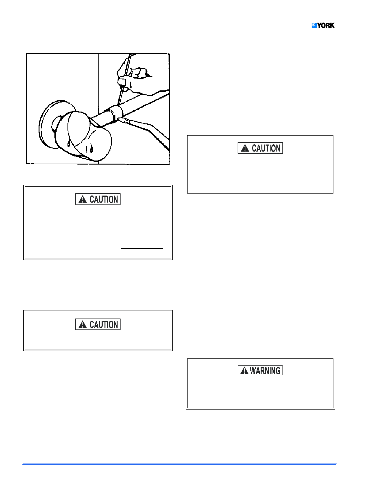
Precautions should be taken to prevent heat damage to
angle valve by wrapping a wet rag around it as shown in Figure 5. Also, protect all painted surfaces and insulation during
brazing. After brazing - cool joint with wet rag.
This is not a backseating valve. The service access
port has a valve core. Opening or clos in g v alv e does
not close service access port.
If the valve stem is backed out pa st the retaining ring,
the O-ring can be damaged causing leakage or system pressure could force the valve stem out of the
valve body possibly causing personal injury. In the
event the retaining ring is missing, do not attempt to
open the valve.
7. Pack fiber glass insulation and a sealing material such
as permagum around refrigerant lines where they penetrate a wall to reduce vibration and to retain some
flexibility.
8. See Form 690.01-AD1V f or a ddi tio nal pi pin g i nfo rma tio n.
PRECAUTIONS DURING BRAZING OF LINES
All outdoor unit and evaporator coil connections are copperto-copper and should be brazed with a phosphorous-copper
alloy mater ial such as Silfos-5 or equivalent. DO NOT use
soft solder.
The outdoor units have re-usable service valves on both the
Unitary Products Group 5
Valve can be opened by removing the plunger cap and fully
inserting a hex wr ench into the stem and ba cking ou t count erclockwise until valve stem just touches retaining ring.
Replace plunger cap finger tight, then tighten an additional 1/
12 turn (1/2 hex flat). Cap must be replaced to prevent leaks.
Connect the refrigerant lines using the following procedure:
1. Remove the cap and Schrader core from both the liquid
and vapor angle valve service ports at the outdoor unit.
Connect low pressure ni trogen to th e liquid lin e service
port.
Page 6
7. Evacuate the vapor line, evapor ator a nd the li quid li ne, to
500 microns or less.
8. Leak test all refrigerant piping connections including the
service port flare caps to be sure they are leak tight. DO
NOT OVERTIGHTEN (between 40 and 60 inch - lbs.
maximum).
FIGURE 5 : HEAT PROTECTION
If visual verification of the valve stem reaching the
retaining ring is imposs ible, stop backing out the.valve
stem when the slighte st incr ease in resistanc e is fel t.
Because of the small size and therefore the reduced
resistance, back out the liquid valv e 5 turns maximu m
to prevent going pas t the r etaini ng r ing.
2. Braze the liquid line to the liquid valve at the outdoor
unit. Be sure to wrap the valv e body with a wet rag. Allow
the nitrogen to continue flowing.
3. Carefully remove the rubber plugs from the evaporator
liquid and vapor connections.
The evaporator is pressurized.
4. Braze the liquid line to the evaporator liquid connection.
The nitrogen sho uld now be flowing through the e vaporator
coil.
NOTE:
Do not use the system refrige rant in the out door unit to
purge or leak test.
9. Do not remove the flare caps from the service ports
except when necessary for servicing the system.
Do not connect manifold gauges unless trouble is
suspected. Approxim ately 3/4 ounce of refrigerant wil l
be lost each time a s tan dard man ifo ld ga uge i s connected.
10. Release the refrigerant charge into the system. Open
both the liquid and vapor valve s by remov in g the pl ung er
cap and with an al le n w re nc h b ac k ou t c oun ter-c lo ck w is e
until valve stem just touches retaining ring. Release the
refrigerant charge into the sys tem. See “Precautions During Brazing Angle Valves" on page 6.
11. If the refrigerant tubing, indoor evaporator coil or outdoor
condensing unit has developed a leak during shipment,
or was, for any other reason, opened to the atmosphere
for more than four (4) minutes, it is necessary to evacuate the system down to at least 500 microns to eliminate
contamination and moisture in the system.
If a leak is suspected, leak test to locate the leak. To verify
the leak, close the valve to the vacuum pump suction to isolate the pump and hold the system under vacuum. If the
micron gauge indicates a steady and continuous rise after a
few minutes, it's an indication of a leak. If the gauge shows a
rise, then levels off after a few minutes and remains fairly
constant, its an indi catio n th at the sys tem i s leak free , bu t stil l
contains moisture and may require further evacuation if the
reading is above 1000 micron s.
5. Slide the grommet away from the vapor connection at
the coil. Braze the vapor line to the evaporator vapor
connection. After the connection has cooled, slide the
grommet back into original position.
6. Protect the vapor valve with a wet rag and braze the
vapor line connection. The nitrogen flow should be exiting the system from the vapor service port connection.
After this connection has cooled, remove the nitrogen
source from the liquid fitting service port.
6 Unitary Products Group
Never attempt to repair any bra zed connections whil e
the system is under pressure. Personal injury could
result.
See "System Start Up" section for checking and recording
system charge.
Page 7
035-17421-000 Rev B (700)
ORIFICE SELECTION
YORKMATE FLOW CONTROL COILS
The proper orifice must be installed in the indoor coil liq-
NOTE:
uid connection prior to the co nnection of the refrigerant
lines.
Sweat coil is under 35 PSIG helium pressure.
Sweat coils are shipped with a standard orifice in a plastic
bag attached to the liquid line connection or factory installed
in the liquid line distributor. The standard orifice size is
marked on the coil data plate.
The orifice that is shipped with the coil is based on the “most
sold” combination, but it may hav e to be chang ed , depen ding
on the capacity and efficiency of the outdoor unit, elevation
differences, and/or long total line lengths. An additional orifice(s) is shipped with most outd oor uni ts in the literature
packet for the most commonly required replacement combinations. Other sizes must be ordered from the Parts Department if required.
See the appropriate Tabular Data Sheet for the correc t orifice
size. If the orifice sizes ma tch, noth ing furthe r is require d and
the refrigerant lines may be connected per the outdoor unit
instruction. However, if another orifice should be used, see
the coil instruction for details to change the orifice in the coil.
POWER WIRING
1. Install the proper size weatherproof disconnect switch
outdoors and within sight of the unit.
2. Run power wiring from the disconnect switch to the unit.
3. Remove the control box cover to gain access to the unit
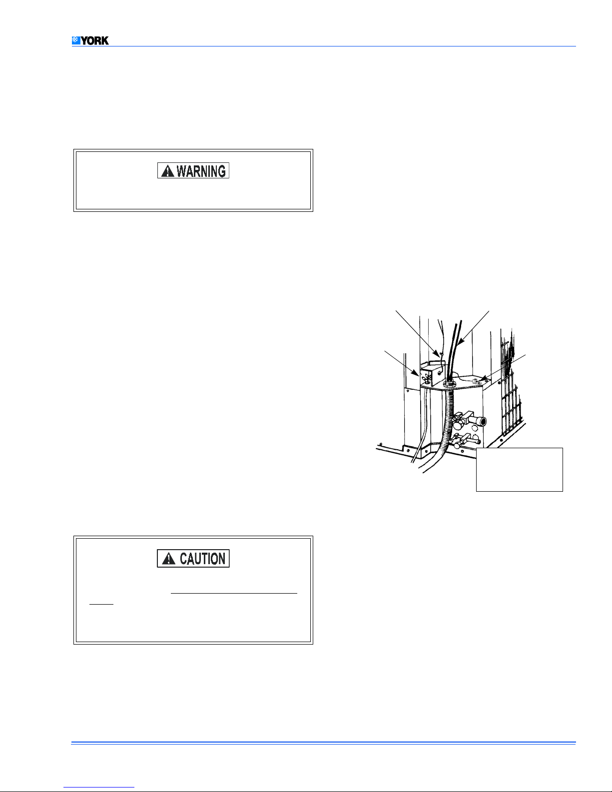
wiring. Route wires from disconnect through power wiring opening provided and into the unit control box as
shown in Figure 6.
4. Install the proper size time-delay fuses or circuit breaker,
and make the power supply connections.
5. Energize the crankcase heater to save time by preheating the compressor oil while the remaining installation is
completed.
CONTROL
WIRING
POWER
WIRING
LOW VOLTAGE
JUNCTION BOX
GROUND
LUG
ELECTRICAL CONNECTIONS
GENERAL INFORMATION & GROUNDING
Check the electrical supply to be sure that it meets the values
specified on the unit nameplate and wiring label.
Power wiring, control (low voltage) wiring, disconnect
switches and over current protection to be supplied by the
installer. Wire size should be sized per NEC requirements.
All field wiring must USE COPPER CONDUCTORS
ONLY and be in accordance with Local, National Fire,
Safety & Electrical Co des. This unit must be grounded
with a separate ground wire in accordance with the
above codes.
The complete connec tion diag ram and sc hematic wiring labe l
is located on the in side surf ace of the unit elec trical box c over
and this instruction.
All outdoor wiring
must be weatherproof. Use copper
conductors only.
FIGURE 6 : TYPICAL FIELD WIRING
ACCESSORY WIRING
The electrical accessories available for this unit are a two
stage cooling thermostat and an optional De-humidification
Control. Refer to the individual instructions packaged with the
accessories for installation.
THERMOSTAT MOUNTING / WIRING
This condensing unit must be installed with the factory recommended thermostat, or any conventional heat pump thermostat.
The thermostat should be located about 5 ft. above the floor,
where it will be exposed to normal room air circulation. Do not
place it on an outside wall or where it is exposed to the radiant effect from exposed glass or appliances, drafts from outside doors or supply air grilles.
Unitary Products Group 7
Page 8
A
ALL WIRING TO BE IN ACCORDANCE WITH NATIONAL ELECTRIC CODE AND/OR LOCAL CODES
R
Y
OUTDOOR UNIT
CONTACTOR
T2
T1
M
L2
L1
GRD.
SCREW
THERMOSTAT
R
B or C
Y
O
W
L or X
G
2
T
2
E
7 WIRES
1
FIELD
INSTALLED
JUMPER
INDOOR UNIT
LOW VOLTAGE TERMINAL BLOCK
IN AIR HANDLER WITH ELECTRIC HEAT
R
C
Y
O
W2
G
W1
3,4
RED
BLK
YEL
ORG
BRN
PRP
WHT
DEFROST
CONTROL
C
O
W
X
W1
1
Jumper terminals E and W to
heat on first stage during
Emergency Heat.
2
Terminal not used on all thermostats.
POWER WIRING
24V CONTROL WIRING
(NEC CLASS 2)
CIRCUIT
BREAKER***
3
Check the low voltage terminal block on the indoor unit for the actual arrangement of the terminals.
4
Connect power wiring to terminal block 3TB on units without electric heat or circuit breaker.
GRD.
LUG
POWER WIRING
208/230-1-60
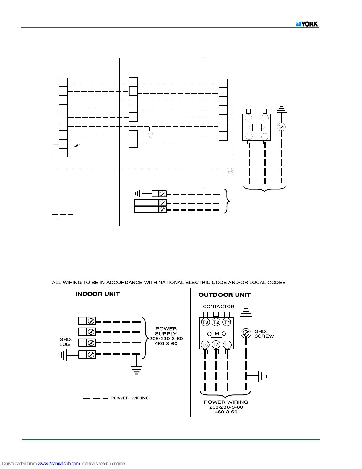
FIGURE 7 : TYPICAL 1 PHASE FIELD WIRING (AIR HANDLER / ELECTRICAL HEAT)
LL WIRING TO BE IN ACCORDANCE WITH NATIONAL ELECTRIC CODE AND/OR LOCAL CODES
INDOOR UNIT
POWER
GRD.
LUG
SUPPLY
208/230-3-60
460-3-60
OUTDOOR UNIT
CONTACTOR
T1
T2T3
M
L2
L3
L1
GRD.
SCREW
POWER WIRING
FIGURE 8 : TYPICAL 3 PHASE FIELD WIRING (AIR HANDLER / ELECTRICAL HEAT)
8 Unitary Products Group
POWER WIRING
208/230-3-60
460-3-60
Page 9
035-17421-000 Rev B (700)
After the thermostat is mounted, route the 24-volt control wiring (NEC Class 2) from the thermostat to the indoor air handler and outdoor unit. Route the control wiring into the
grommeted hole in the bottom of control box of the outdoor
unit. Using wire nuts connect to leads inside the low voltage
junction shown in Figure 6 and wiri ng dia gra ms shown in Figures 7 and 8.
Interconnecting control wiring must be a minimum of No. 18
AWG color coded insulated wires. If wir e lengths increase
more than 90 feet, use No. 16 AWG wires, to prevent excessive voltage drop.
To eliminate erratic operation, seal the hole in the
NOTE:
wall at the thermostat with permagum or equivalent
to prevent air drafts affecting the anticipators in the
thermostat.
EVACUATION
It will be necessary to evacuate the system if the unit has
developed a leak during shipment or was, for any other reason, opened to the atmosphere. If a leak is suspected, leak
test to locate the leak. Repair the leak and test again.
To verify if the system has no leaks, simply close the valve to
the vacuum pump suction to isolate the pump and hold the
system under vacuum. Watch the micron gauge for a few
minutes. If the micron gauge indicates a steady and continuous rise, it’s an indication of a leak. If the gauge sho ws a rise,
then levels off after a few minutes and remains fairly constant, its an indication that the system is leak free but still
contains moisture and may require further evacuation if the
reading is above 500 microns.
REFRIGERANT LINE CHARGES
The outdoor condensi ng unit m ay be conne cte d to the ind oor
evaporator coil using field supplied refrigerant grade copper
tubing that is internally clean and dry. Units should be
installed only with the tubing sizes for approved system combinations as specified in Tabular Data Sheet. The charge
given is applicable for total tubing lengths up to 15 feet. See
Application Data Form 690.01-AD1V for installing tubing of
longer lengths and elevation differences.
Using a larger than specified line size could result in
NOTE:
oil return problem s. Using too smal l a li ne w ill res ul t in lo ss of
capacity and other problems caused by insufficient refrigerant flow. Slope horizon tal v apo r l in es at least 1" every 20 feet
toward the outdoor unit to facilitate proper oil return.
Table 2: REFRIGERANT LINE CHARGES
LIQUID OD VAPOR OD R-22 CHARGE OZ./FT.
3/8" 5/8" 0.66
3/8" 3/4" 0.68
3/8" 7/8" 0.70
3/8" 1-1/8" 0.76
Sweat connect units als o in cl ude sufficient charge for 15 feet
of lines. Table 2 lists the refrigerant line charges.
The “TOTAL SYSTEM CHARGE” must be permanently
stamped on the unit data plate.
Total system charge is determined as follows:
1. Determine outdoor unit charge from tabular data sheet.
Refrigerant chargin g s hou ld onl y b e c arri ed out by a
qualified air conditi oni ng c on trac tor w i th pro pe r cert ification
SYSTEM CHARGE
Refrigerant chargin g s hou ld onl y b e c arri ed out by a
qualified air conditi oni ng c on trac tor w i th pro pe r cert ification.
The factory charge in the outdoor unit includes enough
charge for the unit and a most sold matched evaporator.
2. Determine indoor coil adjustment from tabular data
sheet.
3. Calculate the line charge with the factors in Table 2 for
sweat lines in excess of 15 ft.
NOTE:
The line charge o ver 15 fe et shoul d be inc luded on the
data plate and mu st be add ed to the sy stem .
4. Total system charge = item 1 + item 2 + item 3.
5. Permanently stamp the unit data plate with the total
amount of refrigerant in the system.
USE THE FOLLOWING CHARGING METHOD
WHENEVER ADDITIONAL REFRIGERANT IS
REQUIRED FOR THE SYSTEM CHARGE.
Measurement Method
A calibrated charging cylinder or accurate weighing device
must be used to add refrigerant. This is the only accurate
charging method for heat pumps in the heat pump mode.
Check flare caps on service ports to be sure they are leak
tight. DO NOT OVERTIGHTEN (betwee n 40 and 60 inch-lbs.
maxi-mum).
Unitary Products Group 9
Page 10
Superheat Charging Method
Use this method only during system mainte nance and
NOTE:
repair.
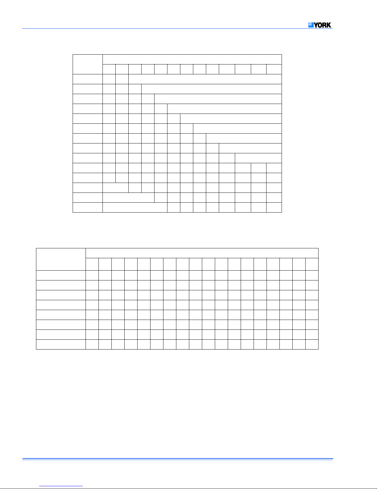
1. Operate system until temperatures and pressures stabilize (minimum of 10 minutes).
2. Measure and record indoor wet bulb (WB) temperature
using a sling psychrometer and the outdoor dry bulb
(DB) temperature using a thermometer.
3. Measure and record the suction pressure at the suction
service valve port.
4. Using Table 3, note the superheat value corresponding
to the intersection of the indoor wet bulb and the outdoor
dry bulb.
5. With th e superheat value obtai ned in step 4 and the suction pressure value from step 3, find the intersection of
the values in Table 4. This is the required suction tube
tempera-ture at the suction service valve.
6. To bring the tube temperature in line with the required
value from Table 4, add refrigerant to the service port to
cause the tube temperat ure to fall and recl aim refrig erant
to cause the temperature to rise.
Check flare caps on Schrader fittings to be sure they are
tight. DO NOT OVERTIGHTEN (40-60 inch-lbs. maximum).
SYSTEM START-UP
ENERGIZE CRANKCASE HEATER
This unit is equipped with a crankcase heater for the compressor.
A warning label with an adhesive back is supplied in the unit
installation instruction packet. This label should be attached
to the field supplied disconnect switch where it will be easily
seen. See below.
door coil which is the condenser. The indoor coil is the
evaporator.
2. If fan switch is in “ON” position, a circuit is made through
blower relay to provide continuous blower operation.
3. When thermostat cooling contact closes, a circuit is
made to energize contactor and start the system, if the
compres-sor has bee n off for 5 minutes. There is an antishort cycle timer built into the defrost control requiring
the compressor to be off at least 5 minutes. With fan
switch in “AUTO” position, a circuit is made from thermostat cooling contact through blower relay to provide
blower operation.
4. System will cycle with thermostat demand to provide
cool-ing as needed.
WITH POWER TO UNIT AND THERMOSTAT IN HEATING
POSITION
1. Reversing valve is de-energized to position refrigerant
cir-cuit for heating operation. In the heating cycle, discharge gas is pumped to the indoor coil which is the co ndenser. The outdoor coil is the evaporator.
2. If fan switch is in “ON” position, a circuit is made through
blower relay to provide continuous blower operation.
3. When first stage of thermostat heating contact closes, a
circuit is made through the control to energize contactor
and start the system, if the compressor has been off 5
minutes. There is an anti-short cycle timer built into the
defrost control requiring the compressor to be off at least
5 min-utes. With fan switch in “AUTO” position, a circuit
is made from thermostat heating contact through blower
relay to provide blower operation.
4. The system will cycle in response to thermostat signal to
provide heating as needed.
5. Supplemental electric heaters are energized by second
stage of heating thermostat.
IMPORTANT
An attempt to start the compressor without at lea st 8
hours of crankcase hea t will damage the compre ssor.
In order to energize the crankcase heater:- Set indoor two
stage cooling thermostat to "OFF" position.- Close the line
power disconnect to the unit.
SYSTEM OPERATION
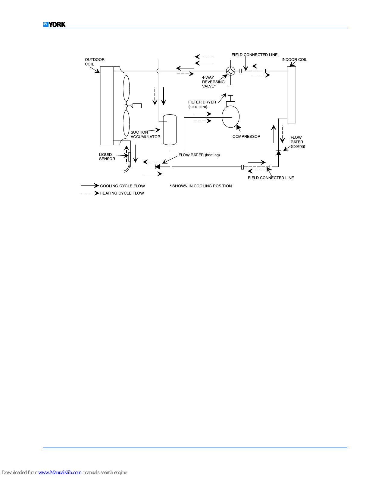
See Figure 9 to trace the flow of refrigerant through the system.
WITH POWER TO UNIT AND THERMOSTAT IN COOLING
POSITION.
1. Reversi ng v a lv e is en er g iz ed t hro ug h t her m os t at sy st em
switch to position refrigerant circuit for cooling operation.
In the cooling cycle, discharge gas is pumped to the out-
10 Unitary Products Group
SEQUENCE OF OPERATION COOLING:
On call for cooling, the thermostat makes 24V circuits: R to
O, R to Y, and R to G. Circuit R to O energizes the reversing
valve, switching it to cool ing positi on. Circu it R to Y energ izes
the contactor, starting outdoor fan motor and compressor
(after the anti-short cyc le period). Ci rcuit R to G en ergizes the
indoor unit blower relay, starting the indoor blower motor.
HEATING:
On call for heating , therm ostat makes c ircuit s R to Y and R to
G. Circuit R to Y energizes contactor, starting outdoor fan
motor and compressor (after the anti-short cycle period). Circuit R to G energizes the indoor blower relay, starting the
blower motor.
Should the temperature continue to fall, R to W is made
through the second stage of the thermostat. Circuit R to W
energizes the supplemental electric heat. The field-installed
Page 11
FLOW
RATER
(cooling)
INDOOR COIL
COMPRESSOR
4-WAY
REVERSING
VALVE*
SUCTION
ACCUMULATOR
OUTDOOR
COIL
COOLING CYCLE FLOW
HEATING CYCLE FLOW
* SHOWN IN COOLING POSITION
FIELD CONNECTED LINE
FIELD CONNECTED LINE
LIQUID
SENSOR
FLOW RATER (heating)
FILTERDRYER
(solidcore).
035-17421-000 Rev B (700)
FIGURE 9 : HEAT PUMP FLOW DIAGRAM
option out-door thermostat can be used to turn on only the
first stage of electric heat if the temperature is above the setting tempera-ture. If gas/propane furnace is used as the supplemental heat, add-on control kit (2AC02700701) must be
used. See the add-on control installation instruction for the
system operation.
EMERGENCY HEAT:
When switch on thermo sta t is placed in emerg ency heat pos ition:
1. Emergency light is energized .
2. Compressor circuit is locked out. (No "R" to "Y")
3. Supplemental and standby heaters (if installed) will be
controlled by first stage of heating thermostat.
4. Indoor blower will operate on demand for heat and cycle
off with the last heater element when in “AUTO” position.
SAFETY LOCKOUT MODE:
The lock out control o pens t he c ircuits t o th e compres sor co n-
tactor , stopping the co mpressor in resp ond to 400 +/-10 PSIG
high pressure limit switch opening for more than 40 milliseconds. The compressor will remain off until the high pressure
switch recloses and a 5 minutes antishort cycle timer has
expired. When the com pressor re-st arts, a six hour ti mer shall
be initialized to ac cu mu lat e th e c om pres so r run time. If the hi
pressure switch opens during his six hour run time, the compressor will be locked-out. If the high pressure switch does
not open during this run time, the unit continues with normal
operation. During locked-out, the defrost relay and the compressor contactor remain de-energized.
If the control detects a high pressure switch opening then it
will send an output to turn on a fault indicator light at the thermostart through X/L terminal. Code flash ed will be eith er 2
flashes if the press ure swi tch o pen s dur ing c ooling or heati ng
mode or 3 flashes if the pressure switch opens during the
defrost mode.
To reset the lock out mode:
1) Remove the 24V power from the Y or/and R for more th an
2 second (turn off the system from the thermostart or power
to the indoor air handler)
2) Connect a 1000 Ohm or smaller jumper across the "test"
terminals for more than 2 seconds
The control has the capability to sense a low voltage condition. If the voltage drops below 18 VAC, the control will not
energize the compressor rel ay. If the unit is running when the
voltage drops, the contactor will remain closed until it drops
below 16 VAC. The antishort cycle timer will be initiated and
the control will not bring the compress or bac k unt il t he anti short cycle period is complete and the voltage is above
18VAC.
DEFROST CYCLE:
The defrost control is a time/temp control which includes a
field-selectable time peri od between defrost cycle (30, 60, or
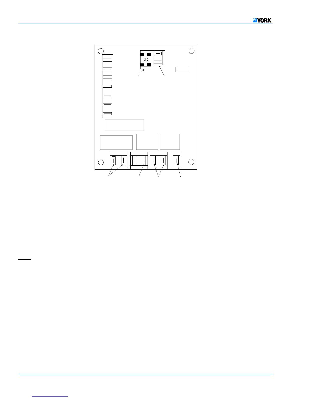
90 minutes). Factory set at 60 minutes. See figure 10.
The electronic timer wil l accumulate the compresso r run time.
At the end of the s etting cy cle time (30. 60, or 90 minut es), the
control will check the defrost thermostat status. If the defrost
thermostat is closed, the defrost cycle will be initiated. The
defrost thermostat is c lo se d whe n the liquid temperature fal ls
Unitary Products Group 11
Page 12
RUN TIME
Tap
30
60
90
RUN TIME
TEST
R7
Test Pin
PN 031-09104-000
6TT-3
X/L
R
C
Time Selection
Y
O
W
W1/66
R3
REV
VALV E
Reversing
Valve
K2
PRESSURE
SWITCH
Pressure
Switch
K1
FIGURE 10 : TIME / TEMPERATURE DEFROST BOARD
below approximately 31F. If the room thermostat opens during defrost, the control will resume operation in defrost when
the thermostat re-closes.
The defrost mode is ident ical to the coolin g mode excep t that
the outdoor fan motor stops and the first stage of heat (5KW if
electric heat) is turned on through w 1/66 to continue w arming
the conditioned space. The defrost cycle will be terminated
when the defrost thermostat is opened at 55F or 10 minutes
of compressor accumulated run time, whichever comes first.
the delay in the response of defrost thermostat may
Note:
allow the coil temperature to reach 75-80F. The 10 minute
timer will stop if the "Y" signal is dropped during defrost.
TEST PIN:
The "test" terminals are designed for two uses:
1. Anti-Short Cycle By-Pass — To by-pass the anti-short
cycle feature in the control, jumper the two "test" terminals for at least 2 seconds. If there is a "Y" signal to the
control, jumpering the test terminal will allow the control
to pull in the unit contactor immediately. Note: do not
hold the jumper on the test terminal for more than 9 seconds as the control will go into the defrost mode.
K3
DEST
T’STAT
Defrost
Thermostat
M
M
Contactor
Coil
terminals mu st be held for at least 10 seconds) . When
the short is removed, the heat pump will remain in
defrost until the defrost thermostat opens or 10 minutes
expires. If the thermostat is open when the short is
removed, the heat pump will exit defrost immediately.
INSTRUCTING THE OWNER
Assist owner with processing warranty cards. Review User’s
Information Manual and provide a copy for the owner guidance on proper operation and maintenance. Instruct the
owner or the operator ho w to start, stop and adjust temperature setting. The owner sh oul d al so be instructed about the 5
minute off cycletimer and the defrost operation.
When applicable, instruct the owner that the compressor is
equipped with a crank case heater to prevent the migra tion of
refrigerant to the compressor during the “OFF” cycle. The
heater is energized only when the unit is not running. If the
main switch is di sconnec ted for long periods of shut dow n, do
not attempt to start the unit for 8 hours after the switch has
been connected. This will allow sufficient time for all liquid
refrigerant to be driven out of the compressor. The installer
should also instruct the owner on proper operation and maintenance of all other system components.
2. Forced Defrost — To force the unit into the defrost mode
(24V to reversing valve and no fan operation) while the
unit is operating, jumper the test terminals for 2 seconds
if the unit was running (If the unit was not running and
step 1 above was used to start the unit, then the "test"
12 Unitary Products Group
INDICATIONS OF PROPER OPERATION
COOLING
Cooling operation is the same as any conventional air condi-
Page 13
035-17421-000 Rev B (700)
tioning unit.
1. The outdoor fan should be running, with warm air being
discharged from the top of the unit.
2. The indoor blower (furnace or air handler) will be operating, discharging cool air from the ducts. coils or other
parts in the air circuit. Clean as often as necessary to
keep the unit clean. Use a brush, vacuum cleaner
attachment, or other suitable means.
3. The vapor line at the outdoor unit will feel cool to the
touch.
4. The liquid line at the outdoor unit will feel warm to the
touch.
HEATING
Indications of proper Heating operation is as follows:
1. The outdo or fan should be runni ng, with cool air bei ng
discharged from the top of the unit.
2. The indoor blower (furnace or air handler) will be opera
ing, discharging warm air from the ducts.
3. The vapor line at the outdoor unit will feel warm to the
touch.
4. The liquid line at the outdoor unit will feel cool to the
touch.
5. The indoor coil drain pan should be inspected and
cleaned regularly to prevent odors and assure proper
drainage.
IT IS UNLAWFUL TO KNOWINGLY VENT, RELEASE OR DISCHARGE REFRIGERANT INTO THE
OPEN AIR DURING REPAIR, SERVICE, MAINTENANCE OR THE FINAL DISPOSAL OF THIS UNIT.
WHEN THE SYSTEM IS FUNCTIONING PROPERLY AND THE OWNER HAS BEEN FULLY
INSTRUCTED, SECURE THE OWNER’S
APPROVAL.
NOTICE TO OWNER
:
If lockout occurs, check the following before calling a serviceman:
1. Indoor section for dirty filter.
2. Outdoor section for snow accumulation.
3. Outdoor section for leaf or debris blockage.
Eliminate problem, turn off the thermostat for 10 seconds and
attempt start. Wait 5 minutes. If system does not start, call
serviceman.
MAINTENANCE
1. Dirt shou ld not be al lowed t o accumu late on th e outd oor
coils or other parts in the air circuit. Clean as often as
necessary to keep the unit cl ean. Use a brus h, vacuum
cleaner attachment, or other suitable means.
2. The outdoor fan motor is permanently lubricated and
does not require periodic oiling.
3. If the coil needs to be cleaned, it should be washed with
Calgon Coilclean (mix one part Coilclean to seven parts
water). Allow solution to remain on coil for 30 minutes
before rinsing with clean water. Solution should not be
permitted to come in contact with painted surfaces.
4. Refer to the furnace or air handler instructions for filter
and blower motor maintenance.
Unitary Products Group 13
Page 14
T able 3: - Superheat Value
INDOOR
*
WB °F
55 60 65 70 75 80 85 90 95 100 105 110 115
OUTDOOR DB°F
50 9 7
52 12 10 6
54 14 12 10 7
56 17 15 14 10 6
58 20 18 16 13 9 5
60 23 21 19 16 12 8 6
62 26 24 22 19 16 12 8 5
64 29 27 24 21 18 15 11 9 6
66 32 31 30 24 23 18 15 11 9 6
68 35 33 30 27 24 21 19 16 14 12 9 6
70 35 33 30 28 25 22 20 18 15 13 11 8
72 35 33 30 28 26 24 20 20 17 15 14
74 34 31 30 27 25 23 22 20 18
76 35 33 31 29 27 26 25 23
*.
Evaporator Entering Air
°F
Table 4: Temperature and Pressure
SUCTION PRES-
SURE PSIG
(Service Port)
61.5 353739414345474951535557596163656769
64.2 373941434547495153555759616365676971
67.1 394143454749515355575961636567697173
70.0 414345474951535557596163656769717375
73.0 434547495153555759616363676971737577
76.0 454749515355575961636567697173757779
79.2 474951535557596163656769717375777981
82.4 495153555759616365676971737577798183
0246810121416182022242628303234
SUCTION SERVICE VALVE SUPERHEAT
14 Unitary Products Group
Page 15
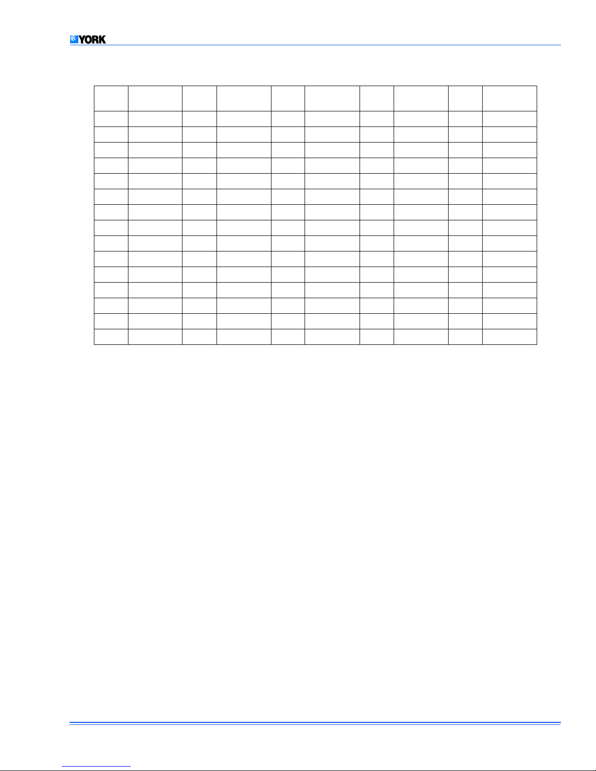
Table 5: Freon 22 Saturation Properties
035-17421-000 Rev B (700)
TEMP
°
F
PRESSURE
PSIG
TEMP
°
F
PRESSURE
PSIG
TEMP
°
F
PRESSURE
PSIG
TEMP
°
F
PRESSURE
PSIG
TEMP
°
F
PRESSURE
45 76.023 60 101.62 75 132.22 90 168.40 105 210.75
46 77.584 61 103.49 76 134.45 91 171.02 106 213.81
47 79.165 62 105.39 77 136.71 92 173.67 107 216.90
48 80.767 63 107.32 78 138.99 93 176.35 108 220.02
49 82.389 64 109.26 79 141.30 94 179.06 109 223.17
50 84.03 65 111.23 80 143.63 95 181.80 110 226.35
51 85.69 66 113.22 81 145.99 96 184,56 111 229.56
52 87.38 67 115.24 82 148.37 97 187.36 112 232.80
53 89.08 68 117.28 83 150.78 98 190.18 113 236.08
54 90.81 69 119.34 84 153.22 99 193.03 114 239.38
55 92.56 70 121.43 85 155.68 100 195.91 115 242.72
56 94.32 71 123.54 86 158.17 101 198.82 116 246.10
57 96.11 72 125.67 87 160.69 102 201.76 117 249.50
58 97.93 73 127.83 88 163.23 103 204.72 118 252.94
59 99.76 74 130.01 89 165.80 104 207.72 119 256.41
PSIG
Unitary Products Group 15
Page 16

035-17421-000 Rev B (700)
NOTES:
Heating and Air Conditioning
Unitary Products Group
5005 York Drive, Norman, Oklahoma 73069
Subject to change without notice. Printed in U.S.A. 035-17421-000 RevB
Copyright © by Unitary Products Group 1999. All rights reserved. Supersedes: 035-17421-000 Rev A (02/00)
 Loading...