

Page 1
TECHNICAL GUIDE
036-21630-001-B-0904
®
DESCRIPTION
YORK Sunline 2000™ heat pumps are convertible single
package units with a common cabinet and a common roof
curb for the 3-6 ton sizes. The units were designed for light
commercial and commercial applications. They can easily be
installed on a roof curb, slab, roof jack or frame.
SINGLE PACKAGE HEAT PUMP UNITS
BP 072
6 NOMINAL TONS
ASHRAE 90.1-2001 COMPLIANT
All units include:
• Powder Paint finish that meets ASTM-B-117 750 hour
salt spray standards
• Permanently lubricated motors
• Bottom or side air discharge configuration capability
(field convertible)
• Manufactured under the quality standards of ISO9001
®
• Simplicity
• Copper tube/aluminum fin coils
• Easy access to all components
• Rigging holes in base rails for lifting
• Fork lift slots on three sides
• Single point power connection
• Complete factory package - tested, charged and wired
• CSA agency listing on all units
WARRANTY
• Factory Limited Parts Warranty
• One-year parts warranty
Control Board
• A Five-year parts warranty on the compressor and
electric heat elements.
FOR DISTRIBUTION USE ONLY - NOT TO BE USED AT POINT OF RETAIL SALE
Page 2

TABLE OF CONTENTS
036-21630-001-B-0904
DESCRIPTION . . . . . . . . . . . . . . . . . . . . . . . . . . . . . 1
PRODUCT NOMENCLATURE . . . . . . . . . . . . . . . . . 3
FEATURES . . . . . . . . . . . . . . . . . . . . . . . . . . . . . . . 11
FACTORY-INSTALLED OPTIONS . . . . . . . . . . . . . 12
FIELD-INSTALLED ACCESSORIES . . . . . . . . . . . 13
GUIDE SPECIFICATIONS . . . . . . . . . . . . . . . . . . . 29
LIST OF FIGURES
Fig. #
1 UNIT CUTAWAY . . . . . . . . . . . . . . . . . . . . . . . . . . . . .12
2 TYPICAL FIELD POWER & CONTROL WIRING. . . . . 23
3 UNIT DIMENSIONS - FRONT VIEW . . . . . . . . . . . . . .24
4 UNIT WITH ECONOMIZER RAINHOOD . . . . . . . . . . .24
5 UNIT WITH FIXED OUTDOOR AIR/MOTORIZED DAMP-
ER RAINHOOD . . . . . . . . . . . . . . . . . . . . . . . . . . . . . .25
6 UNIT DIMENSIONS (REAR VIEW) . . . . . . . . . . . . . . .25
7 DISCONNECT/BLOWER ACCESS LOCATION. . . . . . 26
8 TYPICAL APPLICATIONS . . . . . . . . . . . . . . . . . . . . . .27
9 FOUR AND SIX POINT LOADING . . . . . . . . . . . . . . . .28
10 ROOF CURB DIMENSIONS . . . . . . . . . . . . . . . . . . . .29
Pg. #
LIST OF TABLES
Tbl. #
1 SOUND POWER RATING . . . . . . . . . . . . . . . . . . . . . . 15
2 CAPACITY RATINGS . . . . . . . . . . . . . . . . . . . . . . . . . 15
3 BP072 COOLING CAPACITIES (6 TON) . . . . . . . . . . 16
4 BP072 HEATING CAPACITIES . . . . . . . . . . . . . . . . . . 18
5 SUPPLY AIR BLOWER PERFORMANCE (6 TON BELT
DRIVE) - SIDE DUCT APPLICATION . . . . . . . . . . . . . 18
6 BELT DRIVE BLOWER MOTOR AND DRIVE DATA. . 19
7 STATIC RESISTANCES . . . . . . . . . . . . . . . . . . . . . . . 19
8 ELECTRIC HEATER CFM LIMITATIONS . . . . . . . . . . 19
9 BP 072 ELECTRICAL DATA BELT DRIVE WITHOUT
POWERED CONVENIENCE OUTLET . . . . . . . . . . . . 20
10 BP 072 ELECTRICAL DATA BELT DRIVE WITH
POWERED CONVENIENCE OUTLET . . . . . . . . . . . . 21
11 PHYSICAL DATA . . . . . . . . . . . . . . . . . . . . . . . . . . . . 22
12 ELECTRIC HEAT CORRECTION FACTORS . . . . . . 22
13 VOLTAGE LIMITATIONS . . . . . . . . . . . . . . . . . . . . . . 22
14 UTILITIES ENTRY . . . . . . . . . . . . . . . . . . . . . . . . . . . . 26
15 MINIMUM CLEARANCES . . . . . . . . . . . . . . . . . . . . . . 26
16 BP 4 POINT LOADS WEIGHT DISTRIBUTION . . . . . 28
17 BP 6 POINT LOADS WEIGHT DISTRIBUTION . . . . . 28
18 CENTER OF GRAVITY . . . . . . . . . . . . . . . . . . . . . . . . 28
Pg. #
19 OPERATING WEIGHTS (LBS.) . . . . . . . . . . . . . . . . . . 28
2 Unitary Products Group
Page 3
036-21630-001-B-0904
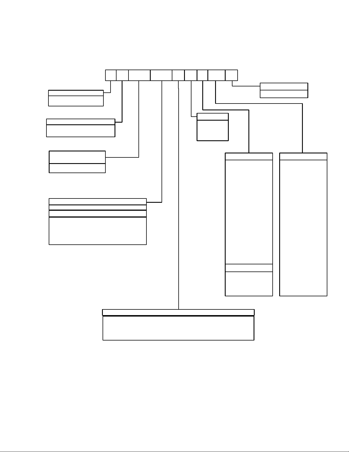
PRODUCT NOMENCLATURE
6 Ton Sunline Model Number Nomenclature
B P C00
Product Category
B = Heat Pump, Single Package
Product Identifier
P = R-22 Hi. Effic. Heat Pump
Nominal Cooling
Capacity - MBH
072 = 6 Ton
Heat Type & Nominal Heat Capacity
C00 = Cooling Only. Suitable for field installed electric heat
Electric Heat Options
E05 = 5 kW Electric Heat
E07 = 7 kW Electric Heat
E10 = 10 kW Electric Heat
E15 = 15 kW Electric Heat
E20 = 20 kW Electric Heat
E30 = 30 kW Electric Heat
AA 1072
A2A
Voltage
2 = 208/230-3-60
4 = 460-3-60
5 = 575-3-60
Product Generation
1 = First Generation
Installation Options
A = No Options Installed
B = Option 1
C = Option 2
D = Options 1 & 2
E = Option 3
F = Option 4
G = Options 1 & 3
H = Options 1 & 4
J = Options 1, 2 & 3
K = Options 1, 2, & 4
L = Options 1,3 & 4
M = Options 1, 2, 3, & 4
N = Options 2 & 3
P = Options 2 & 4
Q = Options 2, 3, & 4
R = Options 3 & 4
S = Option 5
T = Options 1 & 5
U = Options 1, 3, & 5
V = Options 1, 4, & 5
W = Options 1, 3, 4, & 5
X = Options 3 & 5
Y = Options 4 & 5
Z = Options 3, 4, & 5
Options
1 = Disconnect
2 = Non-Pwr'd Conv Oultet
3 = Smoke Detector S.A.
4 = Smoke Detector R.A.
5 = Pwr'd Conv. Outlet
Additional Options
(See Next Page)
Airflow
N = Belt Drive
P = Belt Drive/Single Input Econo
R = Belt Drive/Motorized Damper
Y = Belt Drive/BAS Ready Econ (No BAS Controller) w/2" Pleated Filters
Unitary Products Group 3
Page 4

PRODUCT NOMENCLATURE - Continued
6T Sunline Model Number Nomenclature
Standard Cabinet
AA None
AB Phase Monitor
AC Coil Guard
AD Dirty Filter Switch
AE Phase Monitor & Coil Guard
AF Phase Monitor & Dirty Filter Switch
AG Coil Guard & Dirty Filter Switch
AH Phase Monitor, Coil Guard, & Dirty Filter Switch
AJ SS Drain Pan
AK SS Drain Pan & Phase Monitor
AL SS Drain Pan & Coil Guard
AM SS Drain Pan & Dirty Filter Switch
AN SS Drain Pan, Phase Monitor, Coil Guard & Dirty Filter Switch
AS Bottom Drain Connection
CA CPC Controller with Dirty Filter Switch & Air Proving Switch
CB CPC Controller, DFS, APS & Phase Monitor
CC CPC Controller, DFS, APS & Coil Guard
CD CPC Controller, DFS, APS, Phase Monitor, & Coil Guard
CE CPC Controller, DFS, APS & Technicoat Cond. Coil
CF CPC Controller, DFS, APS, Technicoat Cond. Coil, & Phase Monitor
CG CPC Controller, DFS, APS, Technicoat Cond. Coil, & Coil Guard
CH CPC Controller, DFS, APS, Technicoat Cond. Coil, Phase Monitor, & Coil Guard
CJ CPC Controller, DFS, APS & Technicoat Evap. Coil
CK CPC Controller, DFS, APS, Technicoat Evap. Coil, & Phase Monitor
CL CPC Controller, DFS, APS, Technicoat Evap. Coil, & Coil Guard
CM CPC Controller, DFS, APS, Technicoat Evap. Coil, Phase Monitor, & Coil Guard
CN CPC Controller, DFS, APS & Technicoat Evap. & Cond Coils
CP CPC Controller, DFS, APS, Technicoat Evap. & Cond Coils, & Phase Monitor
CQ CPC Controller, DFS, APS, Technicoat Evap. & Cond Coils, & Coil Guard
CR CPC Controller, DFS, APS, Technicoat Evap. & Cond Coils, Phase Monitor, & Coil Guard
CS CPC Controller, DFS, APS, SS Drain Pan
CT CPC Controller, DFS, APS, SS Drain Pan, Phase Monitor, & Coil Guard
CU CPC Controller, DFS, APS, SS Drain Pan, & Technicoat Cond Coils
CV CPC Controller, DFS, APS, SS Drain Pan, & Technicoat Evap Coil
CW CPC Controller, DFS, APS, SS Drain Pan, & Technicoat Evap and Cond Coils
CX CPC Controller, DFS, APS, SS Drain Pan, Phase Monitor, Coil Guard, & Technicoat Evap and Cond Coils
JA Johnson UNT Controller with Dirty Filter Switch & Air Proving Switch
JB Johnson UNT Controller, DFS, APS & Phase Monitor
JC Johnson UNT Controller, DFS, APS & Coil Guard
JD Johnson UNT Controller, DFS, APS, Phase Monitor, & Coil Guard
JE Johnson UNT Controller, DFS, APS & Technicoat Cond. Coil
JF Johnson UNT Controller, DFS, APS, Technicoat Cond. Coil, & Phase Monitor
JG Johnson UNT Controller, DFS, APS, Technicoat Cond. Coil, & Coil Guard
JH Johnson UNT Controller, DFS, APS, Technicoat Cond. Coil, Phase Monitor, & Coil Guard
JJ Johnson UNT Controller, DFS, APS & Technicoat Evap. Coil
JK Johnson UNT Controller, DFS, APS, Technicoat Evap. Coil, & Phase Monitor
JL Johnson UNT Controller, DFS, APS, Technicoat Evap. Coil, & Coil Guard
JM Johnson UNT Controller, DFS, APS, Technicoat Evap. Coil, Phase Monitor, & Coil Guard
JN Johnson UNT Controller, DFS, APS & Technicoat Evap. & Cond Coils
JP Johnson UNT Controller, DFS, APS, Technicoat Evap. & Cond Coils, & Phase Monitor
JQ Johnson UNT Controller, DFS, APS, Technicoat Evap. & Cond Coils, & Coil Guard
036-21630-001-B-0904
4 Unitary Products Group
Page 5

036-21630-001-B-0904
Standard Cabinet
JR Johnson UNT Controller, DFS, APS, Technicoat Evap. & Cond Coils, Phase Monitor, & Coil Guard
JS Johnson UNT Controller, DFS, APS, SS Drain Pan
JT Johnson UNT Controller, DFS, APS, SS Drain Pan, Phase Monitor, & Coil Guard
JU Johnson UNT Controller, DFS, APS, SS Drain Pan, & Technicoat Cond Coils
JV Johnson UNT Controller, DFS, APS, SS Drain Pan, & Technicoat Evap Coil
JW Johnson UNT Controller, DFS, APS, SS Drain Pan, & Technicoat Evap and Cond Coils
JX Johnson UNT Controller, DFS, APS, SS Drain Pan, Phase Monitor, Coil Guard, & Technicoat Evap and Cond Coils
HA Honeywell Excel 10 Controller with Dirty Filter Switch & Air Proving Switch
HB Honeywell Excel 10 Controller, DFS, APS & Phase Monitor
HC Honeywell Excel 10 Controller, DFS, APS & Coil Guard
HD Honeywell Excel 10 Controller, DFS, APS, Phase Monitor, & Coil Guard
HE Honeywell Excel 10 Controller, DFS, APS & Technicoat Cond. Coil
HF Honeywell Excel 10 Controller, DFS, APS, Technicoat Cond. Coil, & Phase Monitor
HG Honeywell Excel 10 Controller, DFS, APS, Technicoat Cond. Coil, & Coil Guard
HH Honeywell Excel 10 Controller, DFS, APS, Technicoat Cond. Coil, Phase Monitor, & Coil Guard
HJ Honeywell Excel 10 Controller, DFS, APS & Technicoat Evap. Coil
HK Honeywell Excel 10 Controller, DFS, APS, Technicoat Evap. Coil, & Phase Monitor
HL Honeywell Excel 10 Controller, DFS, APS, Technicoat Evap. Coil, & Coil Guard
HM Honeywell Excel 10 Controller, DFS, APS, Technicoat Evap. Coil, Phase Monitor, & Coil Guard
HN Honeywell Excel 10 Controller, DFS, APS & Technicoat Evap. & Cond Coils
HP Honeywell Excel 10 Controller, DFS, APS, Technicoat Evap. & Cond Coils, & Phase Monitor
HQ Honeywell Excel 10 Controller, DFS, APS, Technicoat Evap. & Cond Coils, & Coil Guard
HR Honeywell Excel 10 Controller, DFS, APS, Technicoat Evap. & Cond Coils, Phase Monitor, & Coil Guard
HS Honeywell Excel 10 Controller, DFS, APS, SS Drain Pan
HT Honeywell Excel 10 Controller, DFS, APS, SS Drain Pan, Phase Monitor, & Coil Guard
HU Honeywell Excel 10 Controller, DFS, APS, SS Drain Pan, & Technicoat Cond Coils
HV Honeywell Excel 10 Controller,DFS, APS, SS Drain Pan, & Technicoat Evap Coil
HW Honeywell Excel 10 Controller,DFS, APS, SS Drain Pan, & Technicoat Evap and Cond Coils
HX Honeywell Excel 10 Controller,DFS, APS, SS Drain Pan, Phase Monitor, Coil Guard, & Technicoat Evap and Cond Coils
NA Novar ETC-3 Controller with Dirty Filter Switch & Air Proving Switch
NB Novar ETC-3 Controller, DFS, APS & Phase Monitor
NC Novar ETC-3 Controller, DFS, APS & Coil Guard
ND Novar ETC-3 Controller, DFS, APS, Phase Monitor, & Coil Guard
NE Novar ETC-3 Controller, DFS, APS & Technicoat Cond. Coil
NF Novar ETC-3 Controller, DFS, APS, Technicoat Cond. Coil, & Phase Monitor
NG Novar ETC-3 Controller, DFS, APS, Technicoat Cond. Coil, & Coil Guard
NH Novar ETC-3 Controller, DFS, APS, Technicoat Cond. Coil, Phase Monitor, & Coil Guard
NJ Novar ETC-3 Controller, DFS, APS & Technicoat Evap. Coil
NK Novar ETC-3 Controller, DFS, APS, Technicoat Evap. Coil, & Phase Monitor
NL Novar ETC-3 Controller, DFS, APS, Technicoat Evap. Coil, & Coil Guard
NM Novar ETC-3 Controller, DFS, APS, Technicoat Evap. Coil, Phase Monitor, & Coil Guard
NN Novar ETC-3 Controller, DFS, APS & Technicoat Evap. & Cond Coils
NP Novar ETC-3 Controller, DFS, APS, Technicoat Evap. & Cond Coils, & Phase Monitor
NQ Novar ETC-3 Controller, DFS, APS, Technicoat Evap. & Cond Coils, & Coil Guard
NR Novar ETC-3 Controller, DFS, APS, Technicoat Evap. & Cond Coils, Phase Monitor, & Coil Guard
NS Novar ETC-3 Controller, DFS, APS, SS Drain Pan
NT Novar ETC-3 Controller, DFS, APS, SS Drain Pan, Phase Monitor, & Coil Guard
NU Novar ETC-3 Controller, DFS, APS, SS Drain Pan, & Technicoat Cond Coils
NV Novar ETC-3 Controller, DFS, APS, SS Drain Pan, & Technicoat Evap Coil
NW Novar ETC-3, DF S, APS, SS Drain Pan, & Technicoat Evap and Cond Coils
NX Novar ETC-3 Controller, DFS, APS, SS Drain Pan, Phase Monitor, Coil Guard, & Technicoat Evap and Cond Coils
TA Technicoat Condenser Coil
TB Technicoat Condenser Coil & Phase Monitor
TC Technicoat Condenser Coil & Coil Guard
Unitary Products Group 5
Page 6

036-21630-001-B-0904
Standard Cabinet
TD Technicoat Condenser Coil & Dirty Filter Switch
TE Technicoat Condenser Coil, Phase Monitor, & Coil Guard
TF Technicoat Condenser Coil, Phase Monitor, & Dirty Filter Switch
TG Technicoat Condenser Coil, Coil Guard, & Dirty Filter Switch
TH Technicoat Condenser Coil, Phase Monitor, Coil Guard, & Dirty Filter Switch
TJ Technicoat Evaporator Coil
TK Technicoat Evaporator Coil & Phase Monitor
TL Technicoat Evaporator Coil & Coil Guard
TM Technicoat Evaporator Coil & Dirty Filter Switch
TN Technicoat Evaporator Coil, Phase Monitor, & Coil Guard
TP Technicoat Evaporator Coil, Phase Monitor, & Dirty Filter Switch
TQ Technicoat Evaporator Coil, Coil Guard, & Dirty Filter Switch
TR Technicoat Evaporator Coil, Phase Monitor, Coil Guard, & Dirty Filter Switch
TS Technicoat Evaporator & Condenser Coils
TT Technicoat Evaporator & Condenser Coils & Phase Monitor
TU Technicoat Evaporator & Condenser Coils & Coil Guard
TV Technicoat Evaporator & Condenser Coils & Dirty Filter Switch
TW Technicoat Evaporator & Condenser Coils, Phase Monitor, & Coil Guard
TX Technicoat Evaporator & Condenser Coils, Phase Monitor, & Dirty Filter Switch
TY Technicoat Evaporator & Condenser Coils, Coil Guard, & Dirty Filter Switch
TZ Technicoat Evaporator & Condenser Coils, Phase Monitor, Coil Guard, & Dirty Filter Switch
T1 Technicoat Condenser & SS Drain Pan
T3 Technicoat Condenser Coil, SS Drain Pan, Phase Monitor, Coil Guard, & Dirty Filter Switch
T4 Technicoat Evaporator & SS Drain Pan
T6 Technicoat Evaporator Coil, SS Drain Pan, Phase Monitor, Coil Guard, & Dirty Filter Switch
T7 Technicoat Evaporator & Condenser Coils & SS Drain Pan
T9 Technicoat Evaporator & Condenser Coils, SS Drain Pan, Phase Monitor, Coil Guard, & Dirty Filter Switch
LA Simplicity Intelli-Comfort Controller
LB Simplicity Intelli-Comfort Controller, & Phase Monitor
LC Simplicity Intelli-Comfort Controller, & Coil Guard
LD Simplicity Intelli-Comfort Controller, Phase Monitor, & Coil Guard
LE Simplicity Intelli-Comfort Controller, & Technicoat Cond. Coil
LF Simplicity Intelli-Comfort Controller, Technicoat Cond. Coil, & Phase Monitor
LG Simplicity Intelli-Comfort Controller, Technicoat Cond. Coil, & Coil Guard
LH Simplicity Intelli-Comfort Controller, Technicoat Cond. Coil, Phase Monitor, & Coil Guard
LJ Simplicity Intelli-Comfort Controller, & Technicoat Evap. Coil
LK Simplicity Intelli-Comfort Controller, Technicoat Evap. Coil, & Phase Monitor
LL Simplicity Intelli-Comfort Controller, Technicoat Evap. Coil, & Coil Guard
LM Simplicity Intelli-Comfort Controller, Technicoat Evap. Coil, Phase Monitor, & Coil Guard
LN Simplicity Intelli-Comfort Controller, & Technicoat Evap. & Cond Coils
LP Simplicity Intelli-Comfort Controller, Technicoat Evap. & Cond Coils, & Phase Monitor
LQ Simplicity Intelli-Comfort Controller, Technicoat Evap. & Cond Coils, & Coil Guard
LR Simplicity Intelli-Comfort Controller, Technicoat Evap. & Cond Coils, Phase Monitor, & Coil Guard
LS Simplicity Intelli-Comfort Controller, SS Drain Pan
LT Simplicity Intelli-Comfort Controller, SS Drain Pan, Phase Monitor, & Coil Guard
LU Simplicity Intelli-Comfort Controller, SS Drain Pan, & Technicoat Cond Coils
LV Simplicity Intelli-Comfort Controller, SS Drain Pan, & Technicoat Evap Coil
LW Simplicity Intelli-Comfort Controller, SS Drain Pan, & Technicoat Evap and Cond Coils
LX Simplicity Intelli-Comfort Controller, SS Drain Pan, Phase Monitor, Coil Guard, & Technicoat Evap and Cond Coils
WA Intelli-Comfort w/ModLINC Controller
WB Intelli-Comfort w/ModLINC Controller, & Phase Monitor
WC Intelli-Comfort w/ModLINC Controller, & Coil Guard
WD Intelli-Comfort w/ModLINC Controller, Phase Monitor, & Coil Guard
WE Intelli-Comfort w/ModLINC Controller, & Technicoat Cond. Coil
6 Unitary Products Group
Page 7
036-21630-001-B-0904
Standard Cabinet
WF Intelli-Comfort w/ModLINC Controller, Technicoat Cond. Coil, & Phase Monitor
WG Intelli-Comfort w/ModLINC Controller, Technicoat Cond. Coil, & Coil Guard
WH Intelli-Comfort w/ModLINC Controller, Technicoat Cond. Coil, Phase Monitor, & Coil Guard
WJ Intelli-Comfort w/ModLINC Controller, & Technicoat Evap. Coil
WK Intelli-Comfort w/ModLINC Controller, Technicoat Evap. Coil, & Phase Monitor
WL Intelli-Comfort w/ModLINC Controller, Technicoat Evap. Coil, & Coil Guard
WM Intelli-Comfort w/ModLINC Controller, Technicoat Evap. Coil, Phase Monitor, & Coil Guard
WN Intelli-Comfort w/ModLINC Controller, & Technicoat Evap. & Cond Coils
WP Intelli-Comfort w/ModLINC Controller, Technicoat Evap. & Cond Coils, & Phase Monitor
WQ Intelli-Comfort w/ModLINC Controller, Technicoat Evap. & Cond Coils, & Coil Guard
WR Intelli-Comfort w/ModLINC Controller, Technicoat Evap. & Cond Coils, Phase Monitor, & Coil Guard
WS Intelli-Comfort w/ModLINC Controller, SS Drain Pan
WT Intelli-Comfort w/ModLINC Controller, SS Drain Pan, Phase Monitor, & Coil Guard
WU Intelli-Comfort w/ModLINC Controller, SS Drain Pan, & Technicoat Cond Coils
WV Intelli-Comfort w/ModLINC Controller, SS Drain Pan, & Technicoat Evap Coil
WW Intelli-Comfort w/ModLINC Controller, SS Drain Pan, & Technicoat Evap and Cond Coils
WX Intelli-Comfort w/ModLINC Controller, SS Drain Pan, Phase Monitor, Coil Guard, & Technicoat Evap and Cond Coils
Hinged Filter Door & Toolless Access Cabinet
BA Hinged Filter Door & Toolless Access Panels
BB Phase Monitor, Hinged Filter Door & Toolless Access Panels
BC Coil Guard, Hinged Filter Door & Toolless Access Panels
BD Dirty Filter Switch, Hinged Filter Door & Toolless Access Panels
BE Phase Monitor & Coil Guard, Hinged Filter Door & Toolless Access Panels
BF Phase Monitor & Dirty Filter Switch, Hinged Filter Door & Toolless Access Panels
BG Coil Guard & Dirty Filter Switch, Hinged Filter Door & Toolless Access Panels
BH Phase Monitor, Coil Guard, & Dirty Filter Switch, Hinged Filter Door & Toolless Access Panels
BJ SS Drain Pan & Hinged Filter Door & Toolless Access Panels
BK SS Drain Pan & Phase Monitor, Hinged Filter Door & Toolless Access Panels
BL SS Drain Pan & Coil Guard, Hinged Filter Door & Toolless Access Panels
BM SS Drain Pan & Dirty Filter Switch, H inged Filter Door & Toolless Access Panels
BN SS Drain Pan & Phase Monitor & Coil Guard, Dirty Filter Switch, Hinged Filter Door & Toolless Access Panels
BS Bottom Drain Connection, Hinged Filter Door & Toolless Access Panels
DA CPC Controller with Dirty Filter Switch & Air Proving Switch, Hinged Filter Door & Toolless Access Panels
DB CPC Controller, DFS, APS & Phase Monitor, Hinged Filter Door & Toolless Access Panels
DC CPC Controller, DFS, APS & Coil Guard, Hinged Filter Door & Toolless Access Panels
DD CPC Controller, DFS, APS, Phase Monitor, & Coil Guard, Hinged Filter Door & Toolless Access Panels
DE CPC Controller, DFS, APS & Technicoat Cond. Coil, Hinged Filter Door & Toolless Access Panels
DF CPC Controller, DFS, APS, Technicoat Cond. Coil, & Phase Monitor, Hinged Filter Door & Toolless Access Panels
DG CPC Controller, DFS, APS, Technicoat Cond. Coil, & Coil Guard, Hinged Filter Door & Toolless Access Panels
DH CPC Controller, DFS, APS, Technicoat Cond. Coil, Phase Monitor, & Coil Guard, Hinged Filter Door & Toolless Access Panels
DJ CPC Controller, DFS, APS & Technicoat Evap. Coil, Hinged Filter Door & Toolless Access Panels
DK CPC Controller, DFS, APS, Technicoat Evap. Coil, & Phase Monitor, Hinged Filter Door & Toolless Access Panels
DL CPC Controller, DFS, APS, Technicoat Evap. Coil, & Coil Guard, Hinged Filter Door & Toolless Access Panels
DM CPC Controller, DFS, APS, Technicoat Evap. Coil, Phase Monitor, & Coil Guard, Hinged Filter Door & Toolless Access Panels
DN CPC Controller, DFS, APS & Technicoat Evap. & Cond Coils, Hinged Filter Door & Toolless Access Panels
DP CPC Controller, DFS, APS, Technicoat Evap. & Cond Coils, & Phase Monitor, Hinged Filter Door & Toolless Access Panels
DQ CPC Controller, DFS, APS, Technicoat Evap. & Cond Coils, & Coil Guard, Hinged Filter Door & Toolless Access Panels
DR CPC Controller, DFS, APS, Technicoat Evap. & Cond Coils, Phase Monitor, & Coil Guard, Hinged Filter Door & Toolless Access Panels
DS CPC Controller, DFS, APS, SS Drain Pan Hinged Filter Door & Toolless Access Panels
DT CPC Controller, DFS, APS, SS Drain Pan, Phase Monitor, & Coil Guard Hinged Filter Door & Toolless Access Panels
DU CPC Controller, DFS, APS, SS Drain Pan, & Technicoat Cond Coils Hinged Filter Door & Toolless Access Panels
DV CPC Controller, DFS, APS, SS Drain Pan, & Technicoat Evap Coil Hinged Filter Door & Toolless Access Panels
DW CPC Controller, DFS, APS, SS Drain Pan, & Technicoat Evap and Cond Coils Hinged Filter Door & Toolless Access Panels
Unitary Products Group 7
Page 8

036-21630-001-B-0904
Hinged Filter Door & Toolless Access Cabinet
DX CPC Controller, DFS, APS, SS Drain Pan, Phase Monitor, Coil Guard, & Technicoat Evap and Cond Coils Hinged Filter Door & Toolless
Access Panels
EA Johnson UNT Controller with Dirty Filter Switch & Air Proving Switch, Hinged Filter Door & Toolless Access Panels
EB Johnson UNT Controller, DFS, APS & Phase Monitor, Hinged Filter Door & Toolless Access Panels
EC Johnson UNT Controller, DFS, APS & Coil Guard, Hinged Filter Door & Toolless Access Panels
ED Johnson UNT Controller, DFS, APS, Phase Monitor, & Coil Guard, Hinged Filter Door & Toolless Access Panels
EE Johnson UNT Controller, DFS, APS & Technicoat Cond. Coil, Hinged Filter Door & Toolless Access Panels
EF Johnson UNT Controller, DFS, APS, Technicoat Cond. Coil, & Phase Monitor, Hinged Filter Door & Toolless Access Panels
EG Johnson UNT Controller, DFS, APS, Technicoat Cond. Coil, & Coil Guard, Hinged Filter Door & Toolless Access Panels
EH Johnson UNT Controller, DFS, APS, Technicoat Cond. Coil, Phase Monitor, & Coil Guard, Hinged Filter Door & Toolless Access Panels
EJ Johnson UNT Controller, DFS, APS & Technicoat Evap. Coil, Hinged Filter Door & Toolless Access Panels
EK Johnson UNT Controller, DFS, APS, Technicoat Evap. Coil, & Phase Monitor, Hinged Filter Door & Toolless Access Panels
EL Johnson UNT Controller, DFS, APS, Technicoat Evap. Coil, & Coil Guard, Hinged Filter Door & Toolless Access Panels
EM Johnson UNT Controller, DFS, APS, Technicoat Evap. Coil, Phase Monitor, & Coil Guard, Hinged Filter Door & Toolless Access Panels
EN Johnson UNT Controller, DFS, APS & Technicoat Evap. & Cond Coils, Hinged Filter Door & Toolless Access Panels
EP Johnson UNT Controller, DFS, APS, Technicoat Evap. & Cond Coils, & Phase Monitor, Hinged Filter Door & Toolless Access Panels
EQ Johnson UNT Controller, DFS, APS, Technicoat Evap. & Cond Coils, & Coil Guard, Hinged Filter Door & Toolless Access
Panels
ER Johnson UNT Controller, DFS, APS, Technicoat Evap. & Cond Coils, Phase Monitor, & Coil Guard, Hinged Filter Door &
Toolless Access Panels
ES Johnson UNT Controller, DFS, APS, SS Drain Pan Hinged Filter Door & Toolless Access Panels
ET Johnson UNT Controller, DFS, APS, SS Drain Pan, Phase Monitor, & Coil Guard Hinged Filter Door & Toolless Access Panels
EU Johnson UNT Controller, DFS, APS, SS Drain Pan, & Technicoat Cond Coils Hinged Filter Door & Toolless Access Panels
EV Johnson UNT Controller, DFS, APS, SS Drain Pan, & Technicoat Evap Coil Hinged Filter Door & Toolless Access Panels
EW Johnson UNT Controller, DFS, APS, SS Drain Pan, & Technicoat Evap and Cond Coils Hinged Filter Door & Toolless Access Panels
EX Johnson UNT Controller, DFS, APS, SS Drain Pan, Phase Monitor, Coil Guard, & Technicoat Evap and Cond Coils Hinged Filter Door &
Toolless Access Panels
GA Honeywell Excel 10 Controller with Dirty Filter Switch & Air Proving Switch, Hinged Filter Door & Toolless Access Panels
GB Honeywell Excel 10 Controller, DFS, APS & Phase Monitor, Hinged Filter Door & Toolless Access Panels
GC Honeywell Excel 10 Controller, DFS, APS & Coil Guard, Hinged Filter Door & Toolless Access Panels
GD Honeywell Excel 10 Controller, DFS, APS, Phase Monitor, & Coil Guard, Hinged Filter Door & Toolless Access Panels
GE Honeywell Excel 10 Controller, DFS, APS & Technicoat Cond. Coil, Hinged Filter Door & Toolless Access Panels
GF Honeywell Excel 10 Controller, DFS, APS, Technicoat Cond. Coil, & Phase Monitor, Hinged Filter Door & Toolless Access Panels
GG Honeywell Excel 10 Controller, DFS, APS, Technicoat Cond. Coil, & Coil Guard, Hinged Filter Door & Toolless Access Panels
GH Honeywell Excel 10 Controller, DFS, APS, Technicoat Cond. Coil, Phase Monitor, & Coil Guard, Hinged Filter Door & Toolless Access
Panels
GJ Honeywell Excel 10 Controller, DFS, APS & Technicoat Evap. Coil, Hinged Filter Door & Toolless Access Panels
GK Honeywell Excel 10 Controller, DFS, APS, Technicoat Evap. Coil, & Phase Monitor, Hinged Filter Door & Toolless Access Panels
GL Honeywell Excel 10 Controller, DFS, APS, Technicoat Evap. Coil, & Coil Guard, Hinged Filter Door & Toolless Access Panels
GM Honeywell Excel 10 Controller, DFS, APS, Technicoat Evap. Coil, Phase Monitor, & Coil Guard, Hinged Filter Door & Toolless Access
Panels
GN Honeywell Excel 10 Controller, DFS, APS & Technicoat Evap. & Cond Coils, Hinged Filter Door & Toolless Access Panels
GP Honeywell Excel 10 Controller, DFS, APS, Technicoat Evap. & Cond Coils, & Phase Monitor, Hinged Filter Door & Toolless Access
Panels
GQ Honeywell Excel 10 Controller, DFS, APS, Technicoat Evap. & Cond Coils, & Coil Guard, Hinged Filter Door & Toolless Access Panels
GR Honeywell Excel 10 Controller, DFS, APS, Technicoat Evap. & Cond Coils, Phase Monitor, & Coil Guard, Hinged Filter Door & Too
Access Panels
GS Honeywell Excel 10 Controller, DFS, APS, SS Drain Pan
GT Honeywell Excel 10 Controller, DFS, APS, SS Drain Pan, Phase Monitor, & Coil Guard
GU Honeywell Excel 10 Controller, DFS, APS, SS Drain Pan, & Technicoat Cond Coils
GV Honeywell Excel 10 Controller,DFS, APS, SS Drain Pan, & Technicoat Evap Coil
GW Honeywell Excel 10 Controller,DFS, APS, SS Drain Pan, & Technicoat Evap and Cond Coils
GX Honeywell Excel 10 Controller,DFS, APS, SS Drain Pan, Phase Monitor, Coil Guard, & Technicoat Evap and Cond Coils
PA Novar ETC-3 Controller with Dirty Filter Switch & Air Proving Switch, Hinged Filter Door & Toolless Access Panels
PB Novar ETC-3 Controller, DFS, APS & Phase Monitor, Hinged Filter Door & Toolless Access Panels
lless
8 Unitary Products Group
Page 9

036-21630-001-B-0904
Hinged Filter Door & Toolless Access Cabinet
PC Novar ETC-3 Controller, DFS, APS & Coil Guard, Hinged Filter Door & Toolless Access Panels
PD Novar ETC-3 Controller, DFS, APS, Phase Monitor, & Coil Guard, Hinged Filter Door & Toolless Access Panels
PE Novar ETC-3 Controller, DFS, APS & Technicoat Cond. Coil, Hinged Filter Door & Toolless Access Panels
PF N ovar ETC-3 Controller, DFS, APS, Technicoat Cond. Coil, & Phase Monitor, Hinged Filter Door & Toolless Access Panels
PG Novar ETC-3 Controller, DFS, APS, Technicoat Cond. Coil, & Coil Guard, Hinged Filter Door & Toolless Access Panels
PH Novar ETC-3 Controller, DFS, APS, Technicoat Cond. Coil, Phase Monitor, & Coil Guard, Hinged Filter Door & Toolless Access Panels
PJ Novar ETC-3 Controller, DFS, APS & Technicoat Evap. Coil, Hinged Filter Door & Toolless Access Panels
PK Novar ETC-3 Controller, DFS, APS, Technicoat Evap. Coil, & Phase Monitor, Hinged Filter Door & Toolless Access Panels
PL Novar ETC-3 Controller, DFS, APS, Technicoat Evap. Coil, & Coil Guard, Hinged Filter Door & Toolless Access Panels
PM Novar ETC-3 Controller, DFS, APS, Technicoat Evap. Coil, Phase Monitor, & Coil Guard, Hinged Filter Door & Toolless Access Panels
PN Novar ETC-3 Controller, DFS, APS & Technicoat Evap. & Cond Coils, Hinged Filter Door & Toolless Access Panels
PP Novar ETC-3 Controller, DFS, APS, Technicoat Evap. & Cond Coils, & Phase Monitor, Hinged Filter Door & Toolless Access Panels
PQ Novar ETC-3 Controller, DFS, APS, Technicoat Evap. & Cond Coils, & Coil Guard, Hinged Filter Door & Toolless Access Panels
PR Novar ETC-3 Controller, DFS, APS, Technicoat Evap. & Cond Coils, Phase Monitor, & Coil Guard, Hinged Filter Door & Toolless Access
Panels
PS Novar ETC-3 Controller, DFS, APS, SS Drain Pan
PT Novar ETC-3 Controller, DFS, APS, SS Drain Pan, Phase Monitor, & Coil Guard
PU Novar ETC-3 Controller, DFS, APS, SS Drain Pan, & Technicoat Cond Coils
PV Novar ETC-3 Controller, DFS, APS, SS Drain Pan, & Technicoat Evap Coil
PW Novar ETC-3, DFS, APS, SS Drain Pan, & Technicoat Evap and Cond Coils
PX Novar ETC-3 Controller, DFS, APS, SS Drain Pan, Phase Monitor, Coil Guard, & Technicoat Evap and Cond Coils
UA Technicoat Condenser Coil, Hinged Filter Door & Toolless Access Panels
UB Technicoat Condenser Coil & Phase Monitor, Hinged Filter Door & Toolless Access Panels
UC Technicoat Condenser Coil & Coil Guard, Hinged Filter Door & Toolless Access Panels
UD Technicoat Condenser Coil & Dirty Filter Switch, Hinged Filter Door & Toolless Access Panels
UE Technicoat Condenser Coil, Phase Monitor, & Coil Guard, Hinged Filter Door & Toolless Access Panels
UF Technicoat Condenser Coil, Phase Monitor, & Dirty Filter Switch, Hinged Filter Door & Toolless Access Panels
UG Technicoat Condenser Coil, Coil Guard, & Dirty Filter Switch, Hinged Filter Door & Toolless Access Panels
UH Technicoat Condenser Coil, Phase Monitor, Coil Guard, & Dirty Filter Switch, Hinged Filter Door & Toolless Access Panels
UJ Technicoat Evaporator Coil, Hinged Filter Door & Toolless Access Panels
UK Technicoat Evaporator Coil & Phase Monitor, Hinged Filter Door & Toolless Access Panels
UL Technicoat Evaporator Coil & Coil Guard, Hinged Filter Door & Toolless Access Panels
UM Technicoat Evaporator Coil & Dirty Filter Switch, Hinged Filter Door & Toolless Access Panels
UN Technicoat Evaporator Coil, Phase Monitor, & Coil Guard, Hinged Filter Door & Toolless Access Panels
UP Technicoat Evaporator Coil, Phase Monitor, & Dirty Filter Switch, Hinged Filter Door & Toolless Access Panels
UQ Technicoat Evaporator Coil, Coil Guard, & Dirty Filter Switch, Hinged Filter Door & Toolless Access Panels
UR Technicoat Evaporator Coil, Phase Monitor, Coil Guard, & Dirty Filter Switch, Hinged Filter Door & Toolless Access Panels
US Technicoat Evaporator & Condenser Coils, Hinged Filter Door & Toolless Access Panels
UT Technicoat Evaporator & Condenser Coils & Phase Monitor, Hinged Filter Door & Toolless Access Panels
UU Technicoat Evaporator & Condenser Coils & Coil Guard, Hinged Filter Door & Toolless Access Panels
UV Technicoat Evaporator & Condenser Coils & Dirty Filter Switch, Hinged Filter Door & Toolless Access Panels
UW Technicoat Evaporator & Condenser Coils, Phase Monitor, & Coil Guard, Hinged Filter Door & Toolless Access Panels
UX Technicoat Evaporator & Condenser Coils, Phase Monitor, & Dirty Filter Switch, Hinged Filter Door & Toolless Access Panels
UY Technicoat Evaporator & Condenser Coils, Coil Guard, & Dirty Filter Switch, Hinged Filter Door & Toolless Access Panels
UZ Technicoat Evaporator & Condenser Coils, Phase Monitor, Coil Guard, & Dirty Filter Switch, Hinged Filter Door & Toolless Access Panels
U1 Technicoat Condenser & SS Drain Pan, Hinged Filter Door & Toolless Access Panels
U3 Technicoat Condenser Coil, SS Drain Pan, Phase Monitor, Coil Guard, & Dirty Filter Switch, Hinged Filter Door & Toolless Access Panels
U4 Technicoat Evaporator & SS Drain Pan, Hinged Filter Door & Toolless Access Panels
U6 Technicoat Evaporator Coil, SS Drain Pan, Phase Monitor, Coil Guard, & Dirty Filter Switch, Hinged Filter Door & Toolless Access Panels
U7 Technicoat Evaporator & Condenser Coils & SS Drain Pan, Hinged Filter Door & Toolless Access Panels
U9 Technicoat Evaporator & Condenser Coils, SS Drain Pan, Phase Monitor, Coil Guard, & Dirty Filter Switch, Hinged Filter Door & Toolless
Access Panels
QA Simplicity Intelli-Comfort Controller with Hinged Filter Door & Toolless Access Panels
QB Simplicity Intelli-Comfort Controller, & Phase Monitor, Hinged Filter Door & Toolless Access Panels
QC Simplicity Intelli-Comfort Controller, & Coil Guard, Hinged Filter Door & Toolless Access Panels
Unitary Products Group 9
Page 10

036-21630-001-B-0904
Hinged Filter Door & Toolless Access Cabinet
QD Simplicity Intelli-Comfort Controller, Phase Monitor, & Coil Guard, Hinged Filter Door & Toolless Access Panels
QE Simplicity Intelli-Comfort Controller, & Technicoat Cond. Coil, Hinged Filter Door & Toolless Access Panels
QF Simplicity Intelli-Comfort Controller, Technicoat Cond. Coil, & Phase Monitor, Hinged Filter Door & Toolless Access Panels
QG Simplicity Intelli-Comfort Controller, Technicoat Cond. Coil, & Coil Guard, Hinged Filter Door & Toolless Access Panels
QH Simplicity Intelli-Comfort Controller, Technicoat Cond. Coil, Phase Monitor, & Coil Guard, Hinged Filter Door & Toolless Access
QJ Simplicity Intelli-Comfort Controller, & Technicoat Evap. Coil, Hinged Filter Door & Toolless Access Panels
QK Simplicity Intelli-Comfort Controller, Technicoat Evap. Coil, & Phase Monitor, Hinged Filter Door & Toolless Access Panels
QL Simplicity Intelli-Comfort Controller, Technicoat Evap. Coil, & Coil Guard, Hinged Filter Door & Toolless Access Panels
QM Simplicity Intelli-Comfort Controller, Technicoat Evap. Coil, Phase Monitor, & Coil Guard, Hinged Filter Door & Toolless Access
QN Simplicity Intelli-Comfort Controller, & Technicoat Evap. & Cond Coils, Hinged Filter Door & Toolless Access Panels
QP Simplicity Intelli-Comfort Controller, Technicoat Evap. & Cond Coils, & Phase Monitor, Hinged Filter Door & Toolless Access Pan
QQ Simplicity Intelli-Comfort Controller, Technicoat Evap. & Cond Coils, & Coil Guard, Hinged Filter Door & Toolless Access Panels
QR Simplicity Intelli-Comfort Controller, Technicoat Evap. & Cond Coils, Phase Monitor, & Coil Guard, Hinged Filter Door & Toolles
QS Simplicity Intelli-Comfort Controller, SS Drain Pan Hinged Filter Door & Toolless Access Panels
QT Simplicity Intelli-Comfort Controller, SS Drain Pan, Phase Monitor, & Coil Guard Hinged Filter Door & Toolless Access Panels
QU Simplicity Intelli-Comfort Controller, SS Drain Pan, & Technicoat Cond Coils Hinged Filter Door & Toolless Access Panels
QV Simplicity Intelli-Comfort Controller, SS Drain Pan, & Technicoat Evap Coil Hinged Filter Door & Toolless Access Panels
QW Simplicity Intelli-Comfort Controller, SS Drain Pan, & Technicoat Evap and Cond Coils Hinged Filter Door & Toolless Access Panels
QX Simplicity Intelli-Comfort Controller, SS Drain Pan, Phase Monitor, Coil Guard, & Technicoat Evap and Cond Coils Hinged Filter Door &
Toolless Access Panels
XA Intelli-Comfort w/ModLINC Controller, Hinged Filter Door & Toolless Access Panels
XB Intelli-Comfort w/ModLINC Controller, & Phase Monitor, Hinged Filter Door & Toolless Access Panels
XC Intelli-Comfort w/ModLINC Controller, & Coil Guard, Hinged Filter Door & Toolless Access Panels
XD Intelli-Comfort w/ModLINC Controller, Phase Monitor, & Coil Guard, Hinged Filter Door & Toolless Access Panels
XE Intelli-Comfort w/ModLINC Controller, & Technicoat Cond. Coil, Hinged Filter Door & Toolless Access Panels
XF Intelli-Comfort w/ModLINC Controller, Technicoat Cond. Coil, & Phase Monitor, Hinged Filter Door & Toolless Access Panels
XG Intelli-Comfort w/ModLINC Controller, Technicoat Cond. Coil, & Coil Guard, Hinged Filter Door & Toolless Access Panels
XH Intelli-Comfort w/ModLINC Controller, Technicoat Cond. Coil, Phase Monitor, & Coil Guard, Hinged Filter Door & Toolless Access
XJ Intelli-Comfort w/ModLINC Controller, & Technicoat Evap. Coil, Hinged Filter Door & Toolless Access Panels
XK Intelli-Comfort w/ModLINC Controller, Technicoat Evap. Coil, & Phase Monitor, Hinged Filter Door & Toolless Access Panels
XL Intelli-Comfort w/ModLINC Controller, Technicoat Evap. Coil, & Coil Guard, Hinged Filter Door & Toolless Access Panels
XM Intelli-Comfort w/ModLINC Controller, Technicoat Evap. Coil, Phase Monitor, & Coil Guard, Hinged Filter Door & Toolless Access
XN Intelli-Comfort w/ModLINC Controller, & Technicoat Evap. & Cond Coils, Hinged Filter Door & Toolless Access Panels
XP Intelli-Comfort w/ModLINC Controller, Technicoat Evap. & Cond Coils, & Phase Monitor, Hinged Filter Door & Toolless Access Pan
XQ Intelli-Comfort w/ModLINC Controller, Technicoat Evap. & Cond Coils, & Coil Guard, Hinged Filter Door & Toolless Access Panels
XR Intelli-Comfort w/ModLINC Controller, Technicoat Evap. & Cond Coils, Phase Monitor, & Coil Guard, Hinged Filter Door & Toolle
XS Intelli-Comfort w/ModLINC Controller, SS Drain Pan Hinged Filter Door & Toolless Access Panels
XT Intelli-Comfort w/ModLINC Controller, SS Drain Pan, Phase Monitor, & Coil Guard Hinged Filter Door & Toolless Access Panels
XU Intelli-Comfort w/ModLINC Controller, SS Drain Pan, & Technicoat Cond Coils Hinged Filter Door & Toolless Access Panels
XV Intelli-Comfort w/ModLINC Controller, SS Drain Pan, & Technicoat Evap Coil Hinged Filter Door & Toolless Access Panels
XW Intelli-Comfort w/ModLINC Controller, SS Drain Pan, & Technicoat Evap and Cond Coils Hinged Filter Door & Toolless Access Panels
XX Intelli-Comfort w/ModLINC Controller, SS Drain Pan, Phase Monitor, Coil Guard, & Technicoat Evap and Cond Coils Hinged Filter Door &
Toolless Access Panels
s
10 Unitary Products Group
Page 11

036-21630-001-B-0904
FEATURES
All models are available with a wide variety of factorymounted options such as electric heaters, phase monitor,
convenience outlet, dirty filter switch, disconnect switch,
smoke detectors, and coil guards to make them suitable for
almost every application.
All units are self-contained and assembled on full perimeter
base rails with forklift holes on three sides and holes for overhead rigging. Every unit is completely piped, wired, charged
and tested at the factory to simplify the field installation and to
provide years of dependable operation.
All models (including those with an economizer) are suitable
for either bottom or horizontal duct connections. For bottom
duct, remove the sheet metal panels from the supply and
return air openings through the base of the unit. For horizontal duct, remove the supply and return air panels on the rear
of the unit.
All models are available with these “factory mounted” outdoor
air damper options:
• Single enthalpy economizer
• Motorized outdoor air damper
Supply air blowers are equipped with a belt drive that can be
adjusted to meet the exact requirements of the job.
All compressors are equipped with internal pressure relief.
Every refrigerant circuit includes a liquid line filter-drier, a high
pressure switch and a suction line with a freezestat and low
pressure/loss of charge switch to protect all system components.
®
• Simplicity
standardized a number of features previously available
only as options or by utilizing additional controls.
• Low Ambient - An integrated low-ambient control
• Anti-Short Cycle Protection - To aid compressor
Controls - Simplicity® control boards have
allows all units to operate in the cooling mode down
to 0ºF outdoor ambient without additional assistance. Optionally , the control board can be programmed to lockout the compressors when the
outdoor air temperature is low or when free cooling
is available.
life, an anti-short cycle delay is incorporated into the
standard controls. Compressor reliability is further
ensured by programmable minimum run times. For
testing, the anti short cycle delay can be temporarily
overridden with the push of a button.
• Fan Delays - Fan on and fan off delays are fully programmable and are independent of one another. All
units are programmed with default values based
upon their configuration of cooling and heat.
• Safety Monitoring - The control board monitors the
high and low-pressure switches, the freezestats, the
gas valve, if applicable, and the temperature limit
switch on gas heat units. The unit control board will
alarm on ignition failures, compressor lockouts and
repeated limit switch trips.
• Nuisance Trip Protection- To prevent nuisance
trouble calls, the control board uses a “three strikes,
you’re out” philosophy. The high and low-pressure
switches and the freezestats must trip three times
within two hours before the unit control board will
lock out the compressor.
• On Board Diagnostics - Each alarm will energize a
trouble light on the thermostat, if so equipped, and
flash an alarm code on the control board LED. Each
high and low-pressure switch alarm as well as each
freezestat alarm has its own flash code. The control
board saves the five most recent alarms in memory,
and these alarms can be reviewed at any time.
Alarms and programmed values are retained
through the loss of power.
All units have long lasting powder paint cabinets with 750
hour salt spray test approval under ASTM-B117 procedures.
All models are CSA listed.
• Warranty - All models include a one-year limited parts
warranty on the complete unit. Compressors and electric
heater elements carry a five-year warranty
• Electric Heat Operation - All electric heat models are
wired for a single power source and include a bank of
nickel chromium elements mounted at the discharge of
the supply air blower to provide a high velocity and uniform distribution of air across the heating elements.
Every element is fully protected against excessive temperature by thermal limit switches.
The power supply wiring can be routed into the control
box through a threaded pipe connection (field supplied)
in the base pan of the unit or through a knockout in the
wiring panel on the side of the unit.
• BAS Controls - York’s Sunline™ series units offe r factory mounted BAS controls such as Simplicity
®
INTELLI-
Comfort™, Novar, Honeywell, Johnson, and CPC.
Unitary Products Group 11
Page 12

036-21630-001-B-0904
FIGURE 1 - UNIT CUTAWAY
FACTORY-INSTALLED OPTIONS
• SINGLE INPUT ELECTRONIC ENTHALPY ECONOMIZERS - Includes a slide-in / plug-in damper assembly
with fully modulating spring-return motor actuator capable of introducing up to 100% outdoor air with nominal
1% leakage type dampers.
The enthalpy system contains one sensor that monitors
the outdoor air and determines when the air is cool
enough and dry enough to provide free cooling.
The rainhood is painted to match the basic unit and must
be field-assembled before installing.
• MOTORIZED OUTDOOR AIR INTAKE DAMPER -
Includes a slide-in / plug-in damper assembly with a 2position, spring return motor actuator which opens to a
pre-set position whenever the supply air blower is operating and will drive fully closed when the blower unit
shuts down.
The rain hood is painted to match the basic unit and
must be field assembled before installing.
• PHENOLIC COATED EVAPORATOR AND CON-
DENSER COILS - Special coating process that utilizes
Technicoat 10-1
immersion of the complete coil for maximum protection.
TM
processes. Coating is applied by total
• ELECTRIC HEATERS - Wired for single point power
supply. These nickel chromium heater elements are provided with limit and automatic reset capability to prevent
operation at excessive temperatures.
• FILTER OPTIONS - Standard units are shipped with 1”
throw-away filters installed. 2” pleated filters are offered
as a factory installed option.
• CONVENIENCE OUTLET - This 110 volt outlet can be
“powered” by the unit with a stepdown transformer or the
unit may be ordered with a “non-powered” convenience
outlet that can be wired in the field.
• DISCONNECT SWITCH - For heat pump units with electric heat, an HACR breaker sized to the unit is provided.
For heat pump units without electric heat, a switch sized
to the largest electric heat available for the particular unit
is provided. Factory-installed option only.
• BAS - Building Automation System Controls
Simplicity
Simplicity
®
INTELLI-Comfort™ CONTROL - The York®
®
INTELLI-Comfort™ control is factory
installed. It includes a supply air sensor, a return air sensor, and an outside air sensor . There are provisions for a
field installed dirty filter indicator switch, an air-proving
switch, an Outside Air Humidity sensor, a Return Air
Humidity sensor, an Inside IAQ sensor, and an Outside
12 Unitary Products Group
Page 13

036-21630-001-B-0904
Air IAQ sensor. Construction mode operation, 365-day
real time clock with 7 day programming plus holiday
scheduling is built-in. Two different modes of demand
ventilation are achieved through the INTELLI-Comfort™using CO
sensors. It uses an inside CO2 sensor to
2
perform Demand Ventilation. It can also use an Outside
sensor to perform Differential Demand Ventilation.
CO
2
It uses a Patented Comfort Ventilation algorithm to provide comfortable ventilation air temperature. The patented economizer-loading algorithm will protect the
equipment when harsh operating conditions exist.
Humidity in the occupied space or return duct can be
monitored and controlled via humidity sensors and the
on-board connection for hot gas re-heat system. It uses
the INTELLI-Start™ algorithm to maximize energy savings by recovering the building from the Unoccupied Setpoints to the Occupied Setpoints just in time for the
Occupied Time Period to be g i n. The Simplicity
®
INTELLI-Comfort™ balances space temperature, ventilation air temperature, CO2 and humidity for ultimate
comfort.
• Simplicity® INTELLI-Comfort™ with ModLINC CONTROL - The York® Simplicity® INTELLI-Comfort™ with
ModLINC control is factory installed. It includes all the
features of the INTELLI-Comfort™ control with an additional control to translate communications from MODBUS to the BACnet MSTP protocol.
• Novar® BAS CONTROL - The Novar® ETC-3 building
automation system controller is factory installed.
Includes supply air sensor, return air sensor, dirty filter
indicator switch, and air proving switch.
• JOHNSON CONTROLS BAS CONTROL - The Johnson
Control YK-UNT-1126 build ing automation system controller is factory installed. Includes supply air sensor,
return air sensor, dirty filter indicator switch, and air proving switch.
• CPC BAS CONTROL - The Computer Process Controls
Model 810-3060 ARTC Advanced Rooftop building automation system controller is factory installed. Includes
supply air sensor, return air sensor, dirty filter indicator
switch and air proving switch.
• HONEYWELL BAS CONTROL - The Honeywell
W7750C building automation system controller is factory
installed. Includes air supply sensor, return air sensor,
dirty filter indicator switch, and air proving switch.
• SMOKE DETECTORS - (supply air & return air) The
smoke detectors stop operation of the unit by interrupting
power to the control board if smoke is detected within the
air compartment.
• STAINLESS STEEL DRAIN PAN - An optional rust-
proof stainless steel drain pan is available to provide
years of trouble-free operation in corrosive environments.
• BOTTOM DRAIN CONNECTION - An optional bottom
drain connection is available for inside the curb connections for applications in cold environments to reduce
freezing drain lines.
• COIL GUARD - Customers can purchase a coil guard kit
to protect the condenser coil from damage. This is not a
hail guard kit.
• PHASE MONITORS - Designed to prevent unit damage.
The phase monitor will shut the unit down in an out-ofphase condition.
• DIRTY FILTER SWITCH - This kit includes a differential
pressure switch that energizes the fault light on the unit
thermostat, indicating that there is an abnormally high
pressure drop across the filters. Factory installed option
or field installed accessory.
• HINGED FILTER DOOR/“TOOLLESS” BLOWER AND
ACCESS PANELS (not hinged) - This option allows for
easy access and maintenance.
NOTE:Knobs are shipped inside the unit to prevent ship-
ping damage. These must be field installed for
toolless operation.
FIELD-INSTALLED ACCESSORIES
• SINGLE INPUT ELECTRONIC ENTHALPY ECONOMIZERS - Includes a slide-in / plug-in damper assembly
with fully modulating spring-return motor actuator capable of introducing up to 100% outdoor air with nominal
1% leakage type dampers.
The enthalpy system contains one sensor that monitors
the outdoor air and determines when the air is cool
enough and dry enough to provide free cooling.
The rainhood is painted to match the basic unit and must
be field-assembled before installing.
• MOTORIZED OUTDOOR AIR INTAKE DAMPER -
Includes a slide-in / plug-in damper assembly with a 2position, spring return motor actuator which opens to
some pre-set position whenever the supply air blower is
operating and will drive fully closed when the blower unit
shuts down.
The rain hood is painted to match the basic unit and
must be field assembled before installing.
• ELECTRIC HEATERS wired for single point power sup-
ply. These nickel chromium heater elements are provided with limit and automatic reset capability to prevent
operation at excessive temperatures.
• ROOF CURBS - Eight and fourteen-inch high roof curbs
provide a water-tight seal between the unit and the finished roof. These full perimeter curbs meet the requirements of the National Roofing Contractors Association
(NRCA) and are shipped knocked-down for field assembly.
Unitary Products Group 13
Page 14

036-21630-001-B-0904
Roof curbs are designed to fit inside the base rails of the
unit and include both a wood nailing strip and duct
hanger supports.
• POWER EXHAUST - Our single input economizer
options are available with power exhaust. Whenever the
outdoor air intake dampers are opened for free cooling,
the exhaust fan will be energized to prevent the conditioned space from being over-pressurized during economizer operation.
The power exhaust option can only be used on bottom duct configurations.
• BAROMETRIC RELIEF DAMPER - This damper accessory can be used to relieve internal building air pressure
on units with an economizer without power exhaust. This
accessory includes a rain hood, a bird screen and a fully
assembled damper. With bottom duct connections, the
damper should be mounted over the opening in the
return air panel. With horizontal ductwork, the accessory
should be mounted on the return air duct.
• ENTHALPY ACCESSORY CONTROL KIT - This kit
contains the required components to convert a single
enthalpy economizer to dual enthalpy.
• BURGLAR BARS - Mount in the supply and return
openings to prevent entry into the duct work.
• CO
SENSOR - Senses CO2 levels and automatically
2
overrides the economizer when levels rise above the
present limits.
• COIL GUARD - Customers can purchase a coil guard kit
to protect the condenser coil from damage. This is not a
hail guard kit.
• HAIL GUARD - Hail guard is available to protect the unit
from hail damage. This is a sloped hood that fits above
the coil.
14 Unitary Products Group
Page 15

036-21630-001-B-0904
TABLE 1: SOUND POWER RATING
UNIT
SIZE
CFM
ESP BLOWER
IWG SPEED KW 63 125 250 500 1,000 2,000 4,000 8,000
1
-12
SOUND POWER (db 10
Octave Band Centerline Frequency (Hz)
Watts)
SWL
dB(A)
072 2200 .3 - 1.35 87 87 77 70 72 65 60 55 77 44
1. These values have been accessed using a model of sound propagation from a point source into the hemispheric\free field. The
dBA values provided are to be used for reference only. Calculation of dBA values cover matters of system design and the fan
manufacture has no way of knowing the details of each system. This constitutes and expectation to any specification or guarantee requiring a dBA value or sound data in any other form than sound power level ratings.
2. At a distance of 10 feet from the blower.
TABLE 2: CAPACITY RATINGS
UNIT SIZE
(MBH)
072 68 N/A 10.20 8.4 N/A 69.0 3.2 43.0 2.2
NOTES:
1. Certified in accordance with the Unitary Large Equipment certification program, which is based on ARI Standard 340/360.
2. Rated in accordance with ARI Standard 270.
SEER = Seasonal Energy Efficiency Ratio - the total cooling output in BTU’s during a normal annual usage period for cooling divided by the total electric power input
in watt-hoursduring the same period.
EER = Energy Efficiency Ratio-the cooling capacity in BTU’s per hour (BTUH) divided by the power input in watts at any given set of rating conditions, expressed in
BTUH per watt (BTUH/watt).
COP = Coefficient of Performance - the total heating capacity provided by the refrigeration system, including circulating fan heat but excluding supplementary resistance
(BTU’s per hour) divided by the total electric input (watts) x 3.412.
HSPF = Heating Seasonal Performance Factor - the total heating output during a normal annual usage period for heating divided by the total electric power input during
the same period. (Based on Region IV minimum design heating requirement).
COOLING PERFORMANCE
MBH SEER EER MBH COP MBH COP
SOUND
RATING
bels
ARI RATINGS
2
HSPF
1
HEATING CAPACITY
47°F 17°F
dB(A)
@
10Ft.
2
Unitary Products Group 15
Page 16

TABLE 3: BP072 COOLING CAPACITIES (6 TON)
RETURN AIR
CFM
WB
TEMP
1800
2100
2400
2700
3000
2
GROSS
CAP.
MBH
INPUT
1
POWER
kW
°F
72 76.1 5.26 45.5 39.7 33.8 28.0 22.2 - - 72.6 5.80 43.1 38.0 32.9 27.7 22.6 - -
67 71.2 5.19 57.8 51.9 46.1 40.3 34.4 28.6 22.8 67.0 5.74 55.0 49.9 44.7 39.6 34.5 29.3 24.2
62 66.0 5.13 66.0 62.8 57.0 51.2 45.3 39.5 33.7 60.9 5.67 60.9 59.8 54.7 49.5 44.4 39.3 34.1
57 65.4 5.12 65.4 64.0 58.1 52.3 46.5 40.6 34.8 60.7 5.67 60.7 59.9 54.7 49.6 44.5 39.3 34.2
72 78.9 5.28 49.9 43.4 37.0 30.6 24.2 - - 75.7 5.83 48.2 42.1 36.0 30.0 23.9 - -
67 73.8 5.21 63.3 56.9 50.4 44.0 37.6 31.2 24.8 69.8 5.77 61.2 55.1 49.0 43.0 36.9 30.8 24.8
62 68.3 5.15 68.3 66.8 62.4 56.0 49.6 43.1 36.7 63.4 5.70 63.4 62.9 59.9 53.9 47.8 41.7 35.7
57 67.8 5.14 67.8 67.0 63.6 57.2 50.8 44.4 38.0 63.2 5.70 63.2 62.8 60.0 53.9 47.9 41.8 35.7
72 81.6 5.30 54.2 47.2 40.2 33.2 26.2 - - 78.7 5.86 53.2 46.2 39.2 32.2 25.2 - -
67 76.3 5.23 68.8 61.8 54.8 47.8 40.8 33.8 26.8 72.6 5.80 67.3 60.3 53.3 46.3 39.4 32.4 25.4
62 70.7 5.17 70.7 70.7 67.8 60.8 53.8 46.8 39.8 66.0 5.73 66.0 66.0 65.2 58.2 51.2 44.2 37.2
57 70.1 5.16 70.1 70.1 69.1 62.1 55.1 48.1 41.1 65.7 5.72 65.7 65.7 65.3 58.3 51.3 44.3 37.3
72 83.3 5.31 58.0 50.1 42.1 34.1 26.2 - - 79.6 5.87 56.9 48.9 41.0 33.0 25.0 - -
67 77.9 5.24 73.3 65.3 57.4 49.4 41.4 33.5 25.5 73.4 5.81 70.8 63.7 55.8 47.8 39.8 31.9 23.9
62 72.1 5.18 72.1 72.1 70.7 62.7 54.7 46.8 38.8 66.7 5.74 66.7 66.7 66.3 58.4 50.4 42.4 34.4
57 71.6 5.17 71.6 71.6 71.1 63.1 55.1 47.2 39.2 66.5 5.74 66.5 66.5 66.3 58.3 50.3 42.3 34.4
72 84.9 5.32 61.9 52.9 44.0 35.0 26.1 - - 80.5 5.89 60.6 51.7 42.8 33.8 24.9 - -
67 79.5 5.25 77.8 68.9 59.9 51.0 42.0 33.1 24.2 74.2 5.83 74.2 67.1 58.2 49.3 40.3 31.4 22.4
62 73.6 5.19 73.6 73.6 73.6 64.7 55.7 46.8 37.8 67.5 5.76 67.5 67.5 67.5 58.5 49.6 40.6 31.7
57 73.0 5.18 73.0 73.0 73.0 64.1 55.1 46.2 37.2 67.2 5.76 67.2 67.2 67.2 58.3 49.4 40.4 31.5
85°F 95°F
GROSS SENSIBLE CAPACITY
RETURN AIR DRY BULB TEMP. °F RETURN AIR DRY BULB TEMP. °F
86 83 80 77 74 71 68 86 83 80 77 74 71 68
OUTDOOR AMBIENT TEMPERATURE
1
, MBH
GROSS
CAP.
MBH
INPUT
1
POWER
kW
036-21630-001-B-0904
GROSS SENSIBLE CAPACITY
2
1
, MBH
RETURN AIR
WB
CFM
TEMP
GROSS
CAP.
MBH
1
INPUT
POWER
kW
2
°F
105°F 115°F
GROSS SENSIBLE CAPACITY
RETURN AIR DRY BULB TEMP. °F RETURN AIR DRY BULB TEMP. °F
86 83 80 77 74 71 68 86 83 80 77 74 71 68
1
, MBH
GROSS
CAP.
MBH
GROSS SENSIBLE CAPACITY
2
INPUT
1
POWER
kW
72 67.5 6.47 40.8 35.7 30.6 25.5 20.3 - - 62.3 7.14 38.6 33.4 28.3 23.2 18.0 - -
OUTDOOR AMBIENT TEMPERATURE
1800
67 61.4 6.38 52.1 46.9 41.8 36.7 31.5 26.4 21.3 55.8 7.02 49.2 44.0 38.9 33.8 28.6 23.5 18.4
62 56.3 6.33 56.3 55.4 50.3 45.1 40.0 34.9 29.7 51.8 6.98 51.8 51.0 45.9 40.7 35.6 30.5 25.3
57 55.9 6.31 55.9 55.0 49.9 44.8 39.6 34.5 29.4 51.1 6.95 51.1 50.2 45.0 39.9 34.8 29.6 24.5
72 70.8 6.51 46.1 40.1 34.0 27.9 21.9 - - 66.0 7.19 44.1 38.0 32.0 25.9 19.8 - -
2100
67 64.4 6.41 58.5 52.6 46.5 40.4 34.4 28.3 22.2 59.1 7.06 55.7 50.0 43.9 37.9 31.8 25.7 19.7
62 59.1 6.36 59.1 58.7 55.9 49.8 43.7 37.7 31.6 54.8 7.03 54.8 54.4 51.8 45.7 39.7 33.6 27.5
57 58.6 6.34 58.6 58.2 55.4 49.4 43.3 37.3 31.2 54.0 6.99 54.0 53.6 50.9 44.8 38.8 32.7 26.6
72 74.2 6.55 51.4 44.4 37.4 30.4 23.4 - - 69.6 7.23 49.6 42.6 35.6 28.6 21.6 - -
2400
67 67.4 6.45 64.8 58.2 51.2 44.2 37.2 30.2 23.2 62.3 7.11 62.3 56.0 49.0 42.0 35.0 28.0 21.0
62 61.9 6.40 61.9 61.9 61.5 54.5 47.5 40.5 33.5 57.9 7.07 57.9 57.9 57.8 50.8 43.8 36.8 29.8
57 61.4 6.38 61.4 61.4 61.0 54.0 47.0 40.0 33.0 57.0 7.04 57.0 57.0 56.7 49.7 42.7 35.7 28.7
72 74.3 6.56 54.7 46.8 38.8 30.8 22.8 - - 69.1 7.25 52.5 44.6 36.6 28.6 20.7 - -
2700
67 67.6 6.47 66.3 61.0 53.0 45.1 37.1 29.1 21.2 61.8 7.13 61.8 58.3 50.3 42.3 34.4 26.4 18.4
62 62.1 6.42 62.1 62.1 61.9 53.9 45.9 37.9 30.0 57.4 7.09 57.4 57.4 57.4 49.4 41.4 33.5 25.5
57 61.5 6.40 61.5 61.5 61.3 53.4 45.4 37.4 29.5 56.6 7.06 56.6 56.6 56.4 48.5 40.5 32.5 24.6
72 74.5 6.58 58.0 49.1 40.2 31.2 22.3 - - 68.6 7.27 55.4 46.5 37.6 28.6 19.7 - -
3000
67 67.8 6.49 67.8 63.9 54.9 46.0 37.0 28.1 19.1 61.4 7.15 61.4 60.6 51.6 42.7 33.7 24.8 15.8
62 62.2 6.44 62.2 62.2 62.2 53.3 44.3 35.4 26.5 57.0 7.11 57.0 57.0 57.0 48.1 39.1 30.2 21.2
57 61.7 6.42 61.7 61.7 61.7 52.8 43.8 34.9 25.9 56.1 7.08 56.1 56.1 56.1 47.2 38.3 29.3 20.4
1. These capacities are gross ratings. For net capacity, deduct the supply air blower motor heat, MBH = 3.415 X kW. Refer to the
appropriate blower performance table for the KW of the supply air blower motor.
2. These ratings include condenser fan motor and compressor motor power but not the supply air blower motor power.
1
, MBH
16 Unitary Products Group
Page 17

036-21630-001-B-0904
TABLE 3: BP072 COOLING CAPACITIES (6 TON) - CONTINUED
OUTDOOR AMBIENT TEMPERATURE
RETURN AIR
2
INPUT
1
POWER
kW
CFM
1800
2100
2400
2700
3000
GROSS
CAP.
WB
TEMP
72 57.2 7.81 36.3 31.2 26.0 20.9 15.8 - -
67 50.2 7.66 46.2 41.1 36.0 30.8 25.7 20.6 15.4
62 47.3 7.64 47.3 46.6 41.5 36.3 31.2 26.1 20.9
57 46.2 7.59 46.2 45.3 40.2 35.1 29.9 24.8 19.7
72 61.1 7.87 42.1 36.0 29.9 23.9 17.8 - -
67 53.7 7.71 53.0 47.5 41.4 35.3 29.3 23.2 17.1
62 50.6 7.69 50.6 50.2 47.8 41.7 35.6 29.6 23.5
57 49.5 7.64 49.5 49.0 46.3 40.3 34.2 28.1 22.1
72 65.1 7.92 47.9 40.9 33.9 26.9 19.9 - -
67 57.2 7.76 57.2 53.8 46.8 39.8 32.8 25.8 18.8
62 53.8 7.75 53.8 53.8 53.8 47.0 40.0 33.1 26.1
57 52.7 7.70 52.7 52.7 52.5 45.5 38.5 31.5 24.5
72 63.8 7.94 50.4 42.4 34.4 26.4 18.5 - -
67 56.1 7.79 56.1 55.5 47.6 39.6 31.6 23.6 15.7
62 52.8 7.77 52.8 52.8 52.8 44.9 37.0 29.0 21.0
57 51.6 7.72 51.6 51.6 51.5 43.6 35.6 27.6 19.6
72 62.6 7.97 52.8 43.9 35.0 26.0 17.1 - -
67 54.9 7.81 54.9 54.9 48.3 39.4 30.4 21.5 12.6
62 51.8 7.79 51.8 51.8 51.8 42.8 33.9 24.9 16.0
57 50.6 7.74 50.6 50.6 50.6 41.7 32.7 23.8 14.8
MBH
°F
1. These capacities are gross ratings. For net capacity, deduct the
supply air blower motor heat, MBH = 3.415 X kW. Refer to the
appropriate blower performance table for the KW of the supply air
blower motor.
2. These ratings include condenser fan motor and compressor motor
power but not the supply air blower motor power.
125°F
GROSS SENSIBLE CAPACITY
RETURN AIR DRY BULB TEMP. °F
86 83 80 77 74 71 68
1
, MBH
Unitary Products Group 17
Page 18

TABLE 4: BP072 HEATING CAPACITIES
CFM ID DB
55
1800
70
80
55
2400
70
80
55
3000
70
80
CAP &
KW
-10 0 10 20 30 40 50 60
MBH 14.733 23.633 32.534 41.435 50.336 59.237 68.137 77.038
KW 4.418 4.516 4.614 4.712 4.809 4.907 5.005 5.103
MBH 13.492 22.393 31.293 40.194 49.095 57.996 66.897 75.797
KW 5.105 5.203 5.301 5.399 5.496 5.594 5.692 5.790
MBH 11.260 20.161 29.062 37.962 46.863 55.764 64.665 73.566
KW 5.559 5.657 5.755 5.853 5.950 6.048 6.146 6.244
MBH 16.565 25.466 34.366 43.267 52.168 61.069 69.969 78.870
KW 4.043 4.141 4.239 4.337 4.434 4.532 4.630 4.728
MBH 15.348 24.249 33.149 42.050 50.951 59.852 68.752 77.653
KW 4.737 4.835 4.933 5.031 5.128 5.226 5.324 5.422
MBH 13.007 21.908 30.808 39.709 48.610 57.511 66.411 75.312
KW 5.159 5.257 5.355 5.453 5.550 5.648 5.746 5.844
MBH 17.156 26.057 34.958 43.859 52.759 61.660 70.561 79.462
KW 3.870 3.968 4.066 4.164 4.261 4.359 4.457 4.555
MBH 15.915 24.816 33.717 42.618 51.519 60.419 69.320 78.221
KW 4.557 4.655 4.753 4.851 4.948 5.046 5.144 5.242
MBH 13.684 22.584 31.485 40.386 49.287 58.188 67.088 75.989
KW 5.011 5.109 5.207 5.305 5.402 5.500 5.598 5.696
THE MBH AND KW VALUES DO NOT INCLUDE THE SUPPLY AIR BLOWER MOTOR.
FOR NET CAPACITY, ADD THE SUPPLY AIR BLOWER MOTOR HEAT (MBH = 3.415 X KW)
OUTDOOR AIR TEMPERATURE (°F) (72% RH)
036-21630-001-B-0904
TABLE 5: SUPPLY AIR BLOWER PERFORMANCE (6 TON BELT DRIVE) - SIDE DUCT APPLICATION
UNIT
TONNAGE
1, 2
6
UNIT
TONNAGE
1, 2
6
AIR
FLOW
CFM
3200 1150 2325 1182 2425 1212 2525 --------
3000 1100 2010 1129 2090 1157 2150 1185 2225 1215 2290 1242 2360 - -
2800 1045 1700 1074 1780 1102 1850 1131 1940 1160 2025 1190 2075 1217 2130
2600 985 1425 1015 1475 1045 1540 1075 1630 1103 1715 1135 1760 1163 1825
2400 930 1240 958 1300 990 1350 1020 1400 1051 1430 1081 1490 1111 1600
2200 - - 905 1070 933 1160 965 1210 997 1250 1028 1285 1060 1325
2000 ------9191025 950 1100 982 1130 1014 1160
1800 --------9099259391005 968 1030
AIR
FLOW
CFM
3200 --------------
3000 --------------
2800 1245 2190 ------------
2600 1193 1920 1222 1990 1250 2060 --------
2400 1142 1675 1173 1730 1205 1800 1234 1885 ------
2200 1090 1380 1124 1450 1155 1550 1186 1640 1217 1710 1249 1775 - -
2000 1045 1175 1077 1200 1109 1275 1140 1360 1170 1460 1205 1545 1235 1600
1800 998 1050 1028 1060 1058 1060 1087 1075 1118 1150 1148 1250 1176 1360
1. 230/460/575 Volts
2. For 208 Volts multiply values by 0.95.
3. Includes allowances for a wet evaporator coil, 1” filters, and the heat exchangers. Refer to STATIC RESISTANCE Table for
resistance values on applications other than gas / electric units with side duct airflows.
0.20 0.30 0.40 0.50
RPM WATTS RPM WATTS RPM WATTS RPM WATTS RPM WATTS RPM WATTS RPM WATTS
0.90 1.00 1.10 1.20 1.30 1.40 1.50
RPM WATTS RPM WATTS RPM WATTS RPM WATTS RPM WATTS RPM WATTS RPM WATTS
AVAILABLE EXTERNAL STATIC PRESSURE-IWG
AVAILABLE EXTERNAL STATIC PRESSURE-IWG
3
0.60 0.70 0.80
3
18 Unitary Products Group
Page 19

036-21630-001-B-0904
1000 1200 1400 1600 1800 2000 2200 2400 2600 2800 3000
0.07 0.08 0.09 0.11 0.13 0.15 0.17 0.20 0.23 0.26 0.30
7-15KW 0.04 0.05 0.06 0.07 0.08 0.10 0.12 0.14 0.16 0.19 0.22
20-30KW 0.06 0.07 0.08 0.09 0.11 0.13 0.15 0.17 0.20 0.23 0.26
0.06 0.07 0.08 0.09 0.10 0.11 0.12 0.14 0.16 0.19 0.22
0.08 0.10 0.12 0.14 0.16 0.18 0.20 0.23 0.26 0.29 0.32
COOLING ONLY
2
RESISTANCE, IWG
CFM
DESCRIPTION
ECONOMIZER
1 3
BOTTOM DUCT CONNECTIONS
1
ELECTRIC
HEATERS
1
1. Deduct these resistance values from the available external static pressure shown in SUPPLY AIR BLOWER PERFORMANCE Tables.
3. The pressure through the economizer is greater for 100% outdoor air than for 100% return air. If the resistance of the return air
duct system is less than 0.25 IWG, the unit will deliver less CFM during full economizer operation.
2. Add these resistance values to the available static resistance values on SUPPLY AIR BLOWER PERFORMANCE Tables.
TABLE 6: BELT DRIVE BLOWER MOTOR AND DRIVE DATA
1
MODEL
6 TON 900/1250 1 1/2 56 1VL44 3.1-4.1 2.8-3.8 7/8 AK56 5.4 5.2 1 A36 37.3 1
BLOWER
SIZE
RANGE
(RPM)
1. All motors have solid bases and are in herently p rot ected. t hese mot ors ca n be selecte d t o operat e into t heir service f acto r becau se t hey are locat ed
in the moving air, upstream of any heating device.
MOTOR
HP FRAME
ADJUSTABLE MOTOR PULLEY FIXED BLOWER PULLEY
DESIG-
NATION
OUTSIDE
DIA.
(IN.)
PITCH
DIA.
(IN.)
BORE
(IN.)
DESIG-
NATION
OUTSIDE
DIA.
(IN.)
PITCH
DIA.
(IN.)
BORE
(IN.)
DESIG-
NATION
BELT
(NOTCHED)
PITCH
LENGTH
(IN.)
TABLE 7: STATIC RESISTANCES
QTY.
TABLE 8: ELECTRIC HEATER CFM LIMITATIONS
UNIT MODEL SIZE NOMINAL
TONS
6
VOLTAGE
5 7 10 15 20 30
208/230-1-60 1800 1800 1800 1800 1800 1800
208/230-3-60 1800 1800 1800 1800 1800 1800
460-3-60 - 1800 1800 1800 1800 1800
575-3-60 - - 1800 1800 1800 1800
MINIMUM SUPPLY AIR CFM
HEATER SIZE NOMINAL KW
Unitary Products Group 19
Page 20

036-21630-001-B-0904
TABLE 9: BP 072 ELECTRICAL DATA BELT DRIVE WITHOUT POWERED CONVENIENCE OUTLET
Model
Tonnage
Voltage
208-3-60
Compressors
RLA Each LRA Each
19.2 146
OD
Fan
Motor
FLA
2.3 5.2 0.0
ID
Blower
Motor
FLA
Conv
Outlet
Amps
Electric Heater
Model No.
NONE 0.0 31.5 40
2CE04510525
2CE04510725
Heater
2
2
Heater
kW
Amps
0.0
4.0 11.1 45.4 60
5.6 15.5 50.9 60
2CE04511025 8.0 22.2 59.3 70
2CE04511525 11.9 33.0 72.8 80
2CE04512025 15.9 44.1 86.7 90
2CE04513025 22.2 61.6 108.5 110
230-3-60 19.2 146 2.3 5.2 0.0
NONE 0.0 31.5 40
2CE04510525
2CE04510725
2CE04511025 10.6 25.5 63.4 70
0.0
2
5.3 12.7 47.4 60
2
7.5 18.0 54.1 60
2CE04511525 15.9 38.2 79.3 80
6
2CE04512025 21.2 51.0 95.2 100
2CE04513025 29.6 71.2 120.5 125
0.0
2
6.8 8.2 24.5 30
2
10.1 12.1 29.5 30
2
13.6 16.4 34.7 35
2
19.5 23.5 43.6 45
2
28.8 34.6 57.6 60
0.0
460-3-60
8.3 73
1.3 2.6 0.0
NONE 0.0 14.3 20
2CE04510746
2CE04511046
2CE04511546
2CE04512046
2CE04513046
NONE 0.0 11.9 15
2CE04511058 10.6 10.2 24.7 25
575-3-60
1.0 2.0 0.07.1 60
2CE04511558 15.9 15.3 31.0 35
2CE04512058 21.2 20.4 37.4 40
2CE04513058 30.4 29.3 48.5 50
Note 1: HACR Type per NEC
Note 2: These electric heaters DO NOT include a fuse box. If a fuse box is required to meet a local code
(i.e. Chicago), the fuse block accessories shown below are available for field installation.
Fuse Block
2FB04700425
2FB04700546
Minimum
Circuit
Ampacity
Amps
Max
Fuse /
BRKR
Size
1
20 Unitary Products Group
Page 21

036-21630-001-B-0904
NONE 0.0 41.5 60
2CE04510525
2
4.0 11.1 55.4 70
2CE04510725
2
5.6 15.5 60.9 70
2CE04511025 8.0 22.2 69.3 80
2CE04511525 11.9 33.0 82.8 90
2CE04512025 15.9 44.1 96.7 100
2CE04513025 22.2 61.6 118.5 125
NONE 0.0 41.5 50
2CE04510525
2
5.3 12.7 57.4 70
2CE04510725
2
7.5 18.0 64.1 70
2CE04511025 10.6 25.5 73.4 80
2CE04511525 15.9 38.2 89.3 90
2CE04512025 21.2 51.0 105.2 110
2CE04513025 29.6 71.2 130.5 150
NONE 0.0 19.3 25
2CE04510746
2
6.8 8.2 29.5 35
2CE04511046
2
10.1 12.1 34.5 35
2CE04511546
2
13.6 16.4 39.7 40
2CE04512046
2
19.5 23.5 48.6 50
2CE04513046
2
28.8 34.6 62.6 70
NONE 0.0 15.9 20
2CE04511058 10.6 10.2 28.7 30
2CE04511558 15.9 15.3 35.0 40
2CE04512058 21.2 20.4 41.4 45
2CE04513058 30.4 29.3 52.5 60
Note 1: HACR Type per NEC
Note 2: These electric heaters DO NOT include a fuse box. If a fuse box is required to meet a local code
(i.e. Chicago), the fuse block accessories shown below are available for field installation.
Model
Tonnage
Voltage
Minimum
Circuit
Ampacity
Amps
Max
Fuse /
BRKR
1
Size
RLA Each LRA Each
ID
Blower
Motor
FLA
Conv
Outlet
Amps
Electric Heater
Model No.
Heater
kW
OD
Fan
Motor
FLA
Heater
Amps
2.3 5.2 10.0
230-3-60 19.2 146 2.3 5.2 10.0
208-3-60
1.3 2.6 5.0
575-3-60 1.0 2.0 4.0
460-3-60 73
7.1
Fuse Block
2FB04700425
2FB04700546
6
19.2 146
60
8.3
Compressors
0.0
0.0
0.0
0.0
TABLE 10: BP 072 ELECTRICAL DATA BELT DRIVE WITH POWERED CONVENIENCE OUTLET
Unitary Products Group 21
Page 22

TABLE 11: PHYSICAL DATA
EVAPORATOR
BLOWER
EVAPORATOR
COIL
CONDENSER
FANS
CONDENSER
COILS
COMPRESSOR
(Qty. Per Unit)
AIR
FILTERS
CHARGE
036-21630-001-B-0904
MODELS BP 072
Centrifugal Blower (Dia. x Wd. in .) 12 X 10
Fan Motor HP (Belt Drive) 1 1/2
Rows Deep 4
Fins Per Inch 13
Face Area (Sq. Ft.) 5.1
Propeller Dia. (in.) 24
Fan Motor Hp 1/2
Nom. CFM 4500
Rows Deep 2
Fins Per Inch 18
Face Area (Sq. Ft.) 17.1
Scroll Type 1
Quantity Per Unit (15” X 20” X 1” or 2“) 2
Quantity Per Unit (14” X 25” X 1” or 2“) 1
Total Face Area (sq. ft.) 6.6
Refrigerant 22
(lbs./oz.)
12/0
TABLE 12: ELECTRIC HEAT CORRECTION
FACTORS
NOMINAL VOLTAGE VOLTAGE
208
240
480
600
208 1.00
230 0.92
460 0.92
575 0.92
kW CAP. MULTI-
PLIER
TABLE 13: VOLTAGE LIMITATIONS
POWER SUPPLY
208/230-3-60
460-3-60
575-3-60
1. Utilization Range “A” in accordance with ARI Standard
110.
MIN. MAX.
187 253
414 506
518 506
1
VOLTAGE
22 Unitary Products Group
Page 23

036-21630-001-B-0904
RC
RH
Y1
Y2
W1
W2
G
LED 1
LED 2
COM
A1
A2
T
T
B
R
Y1
Y2
G
C
X
OCC
W2
W1
THERMOSTAT
1
TERMINALS
UNIT TERMINAL
STRIP TB1
24 VOLT
TRANSFORMER
TO REMOTE SENSOR
2TH040702224 IF USED
NOT
USED
ADD
JUMPER
ADD
JUMPER
4
4
3
2
1
ELECTRONIC PROGRAMMABLE THERMOSTAT 2ET04700224 (INCLUDES SUBBASE).
2
SECOND STAGE COOLING IS NOT REQUIRED ON UNITS LESS ECONOMIZER.
3
SECOND STAGE HEATING IS ONLY REQUIRED ON UNITS WITH A TWO STAGE
ELECTRIC HEATER.
4
RH
RC
Y
W
G
R
Y1
W1
C
G
ADD
JUMPER
THERMOSTAT
1
TERMINALS
UNIT TERMINAL
STRIP TB1
24 VOLT
TRANSFORMER
1
ELECTRONIC PROGRAMMABLE THERMOSTAT 2ET07701024 (INCLUDES SUBBASE).
TO CONTROL THE ECONOMIZER ON SECOND STAGE COOLING, USE THERMOSTAT
2TH04700224.
COOLING / HEATING (ELECTRONIC THERMOSTAT)
SINGLE STAGE
TYPICAL POWER WIRING
REFER TO THE ELECTRICAL DATA
TABLES TO SIZE THE DISCONNECT
SWITCH, OVERCURRENT PROTECTION AND WIRING.
TYPICAL CONTROL WIRING
COOLING / HEATING (24 VOLT THERMOSTAT)
THERMOSTAT
TERMINALS
ADD
JUMPER
1
RH
RC
UNIT TERMINAL
STRIP TB1
R
1
24 VOLT THERMOSTAT 2ET07701024. TO CONTROL THE ECONOMIZER ON THE SECOND
STAGE COOLING OR TO HAVE AN ELECTRIC HEAT ACCESSORY WITH TWO STAGES OF
HEAT, USE THERMOSTAT 2TH0471024.
COOLING / HEATING (ELECTRONIC THERMOSTAT)
MULTI STAGE
FIGURE 2 - TYPICAL FIELD POWER & CONTROL WIRING
REMOVE JUMPER J2 FROM TERMINALS 4 AND 9 ON JUMPER PLUG CONNECTOR
P6 ON UNITS WITH ECONOMIZER. TERMINALS A1 ANDA2 PROVIDE A RELAY
OUT-PUT TO CLOSE THE OUTDOOR ECONOMIZER DAMPERS WHEN THE
THERMOSTAT SWITCHES TO THE SET-BACK POSITION.
Unitary Products Group 23
W1
Y1
W2
24 VOLT
Y2
G
C
TRANSFORMER
Y
W
G
Page 24

036-21630-001-B-0904
FIGURE 3 - UNIT DIMENSIONS - FRONT VIEW
FIGURE 4 - UNIT WITH ECONOMIZER RAINHOOD
DETAIL “A”
24 Unitary Products Group
Page 25

036-21630-001-B-0904
DETAIL “B”
FIGURE 5 - UNIT WITH FIXED OUTDOOR AIR/MOTORIZED DAMPER RAINHOOD
FIGURE 6 - UNIT DIMENSIONS (REAR VIEW)
Unitary Products Group 25
Page 26

FILTER
ACCESS
BLOWER MOTOR
ACCESS
DOT PLUGS
FIELD-SUPPLIED
DISCONNECT SWITCH
LOCATION
MOUNTING BRACKET
FOR DICONNECT SWITCH
(Shipped attached to the
blower housing inside
the blower compartment )
A,B
WIRING ENTRY
(See Detail “B”)
DISCONNECT SWITCH LOCATION
AND MOTOR ACCESS PANEL FOR
UNIT WITH “BELT-DRIVE” OPTION
FIGURE 7 - DISCONNECT/BLOWER ACCESS LOCATION
CONTROL BOX
ACCESS
036-21630-001-B-0904
TABLE 14: UTILITIES ENTRY
HOLE OPENING SIZE (DIA.) USED FOR
A
B
C
D
1. Opening in the bottom to the unit can be located by the
side in the insulation.
2. Do not remove the 2” knockout ring.
1
7/8” KO
2” KO
1
Control Wiring
Power Wiring
1-5/8” KO Gas Piping (Front)
1-1/2” KO
Gas Piping (Bottom)
TABLE 15: MINIMUM CLEARANCES
LOCATION
Side
2
Bottom
Side
Bottom
Front
Rear
Left Side (Filter Access)
Right Side (Cond. Coil)
Below Unit
Above Unit
1
2
1. Units may be installed on combustible floors made
from wood or class A, B, or C roof covering material.
2. Units must be installed outdoors. Overhanging structures or shrubs should not obstruct condenser air discharge outlet.
CLEARANCE
24” (Cooling/Electric Heat)
32” (Gas Heat)
12” (Less Economizer)
36” (With Economizer or Fixed
Air/Motorized Damper)
24” (Less Economizer)
36” (With Economizer)
24”
0”
72” (For
Condenser Air Discharge)
26 Unitary Products Group
Page 27

036-21630-001-B-0904
FIGURE 8 - TYPICAL APPLICATIONS
Unitary Products Group 27
Page 28

036-21630-001-B-0904
447/
8
A
BACK OF UNIT
821/
4
D
X
APPROXIMATE
CENTER OF GRAVITY
FRONT OF UNIT
C
B
CONDENSER COIL
Y
END OF UNIT
FIGURE 9 - FOUR AND SIX POINT LOADING
TABLE 16: BP 4 POINT LOADS WEIGHT DISTRIBUTION
UNIT TOTALABCD
BP072
TABLE 17: BP 6 POINT LOADS WEIGHT DISTRIBUTION
UNIT TOTAL A B C D E F
BP072
TABLE 18: CENTER OF GRAVITY
DIMENSION 3 - 5 TON
X 40-¾”
Y 19-¾”
612 136 133 170 173
612919089113114116
447/
8
F
X
APPROXIMATE
CENTER OF GRAVITY
A
FRONT OF UNIT
BACK OF UNIT
821/
4
B
E
D
C
CONDENSER COIL
Y
END OF UNIT
TABLE 19: OPERATING WEIGHTS (LBS.)
MODEL SIZE 6 TON
BASIC UNIT
OPTIONS
Electric Heater
ACCY.
BP 612
Economizer 50
Motorized Damper 26
5 - 7 kW 18
10 - 15 kW 23
20 - 30 kW 28
Roof Curb 92
Barometric Relief / Fixed Air Damper 10
28 Unitary Products Group
Page 29

036-21630-001-B-0904
FIGURE 10 - ROOF CURB DIMENSIONS
GUIDE SPECIFICATIONS
GENERAL
Units shall be manufactured by York International Unitary
Products Group in an ISO 9001 certified facility.
TM
York's Sunline 2000
heat pumps. Although the units are primarily designed for
curb mounting on a roof, they can also be slab-mounted at
ground level or set on steel beams above a finished roof.
Models are available with a wide variety of factory-mounted
options and field-installed accessories to make them suitable
for almost every application. All units are self-contained and
assembled on full perimeter base rails with holes in the four
corners for overhead rigging. Every unit is completely piped,
wired, charged and tested at the factory to simplify the field
installation and to provide years of dependable operation. All
models (including those with an economizer) are suitable for
either bottom or horizontal duct connections. Models with
power exhaust are suitable for bottom duct connections only.
For bottom duct, remove the sheet metal panels from the
supply and return air openings through the base of the unit.
For horizontal duct, remove the supply and return air panels
on the rear of the unit.
All non-Scroll compressors include crankcase heaters and all
compressors have internal pressure relief. Every refrigerant
circuit includes a liquid line filter-drier, a discharge line high
pressure switch and a suction line with a freezestat and low
pressure/loss of charge switch.The unit control circuit
units are convertible single package
includes a 75 VA transformer, a 24-volt circuit breaker and a
relay board with a compressor lockout circuit, a terminal strip
for thermostat wiring, plus an additional set of pin connectors
to simplify the interface of additional field controls. All units
have long lasting powder paint cabinets with 750 hour salt
spray test approval under ASTMB117 procedures. All models
are CSA listed. All models include a 1-year limited warranty
on the complete unit. Compressors and electric heater elements carry a 5-year warranty.
DESCRIPTION
Units shall be factory-assembled, single packaged heat
pumps designed for outdoor mounted installation.
The units shall have minimum EER ratings of 10.2. They shall
have built-in field convertible duct connections for down discharge supply/return or horizontal discharge supply/return,
and be available with factory installed options or field installed
accessories. The units shall be factory wired, piped, charged
with R-22 refrigerant and factory tested prior to shipment. All
unit wiring shall be both numbered and color coded. All units
the cooling performance shall be rated in accordance with
DOE and ARI test procedures. Units shall be CSA listed,
classified to ANSI Z21.47, UL 1995/CSA No. 236 standards.
UNIT CABINET
Unit cabinet shall be constructed of G90 galvanized steel,
with exterior surfaces coated with a non-chalking, powdered
paint finish, certified at 750 hours salt spray test per
ASTMB117 standards. Indoor blower section shall be insu-
Unitary Products Group 29
Page 30

036-21630-001-B-0904
lated with a minimum 1/2” thick insulation, coated on the ai rside. Aluminum foil faced insulation shall be used in the
furnace compartment and be fastened with ridged fasteners
to prevent insulation from entering the air stream. Cabinet
panels shall be “large” size, easily removable for servicing
and maintenance. Full perimeter base rails shall be provided
to assure reliable transit of equipment, overhead rigging and
proper sealing on roof curb applications. Disposable 1" filters
shall be furnished and be accessible through a removable
access door, sealed airtight. Units filter track shall be
designed to accommodate either 1” or 2” filters. Fan performance measuring ports shall be provided on the outside of
the cabinet to allow accurate air measurements of evaporator
fan performance without removing panels or creating air bypass of the coils. Condensate pan shall be internally sloped
and conform to ASHRAE 62-89 self-draining standards. Condensate connection shall be a minimum of 3/4” I.D. female
and be a ridged mount connection.
INDOOR (EVAPORATOR) FAN ASSEMBLY
The indoor fan shall be a factory installed belt drive assembly
that includes an adjustable pitch motor pulley. Job site
selected (B.H.P.) brake horsepower shall not exceed the
motors nameplate horsepower rating, plus the service factor.
Units shall be designed not to operate above service factor.
Fan wheel shall be double-inlet type with forward-curved
blades, dynamically balanced to operate smoothly throughout
the entire range of operation. Airflow design shall be constant
air volume. Bearings shall be sealed and permanently lubricated for longer life and no maintenance.
OUTDOOR (CONDENSER) FAN ASSEMBLY
The outdoor fan shall be of the direct-driven propeller type,
discharge air vertically, have aluminum blades riveted to a
corrosion resistant steel spider bracket and shall be dynamically balanced for smooth operation. The outdoor fan motor
shall be totally enclosed with permanently lubricated bearings, internally protected against overload conditions and
staged independently.
REFRIGERANT COMPONENTS
Compressor:
a. Shall be internally protected with internal high-pres-
sure relief and over temperature protection.
b. Shall have internal spring isolation and sound muf-
fling to minimize vibration and noise, and be externally isolated on a dedicated, independent
mounting.
Coils:
a. Evaporator and condenser coils shall have alumi-
num plate fins mechanically bonded to seamless
internally enhanced copper tubes with all joints
brazed. Special Phenolic coating shall be available
as a factory option.
b. Evaporator and Condenser coils shall be of the
direct expansion, draw-thru, design.
Refrigerant Circuit and Refrigerant Safety Components shall
include:
a. Independent fixed-orifice expansion devices.
b. Filter drier/strainer to eliminate any moisture or for-
eign matter.
c. Accessible service gage connections on both suc-
tion and liquid lines to charge, evacuate, and measure refrigerant pressure during any necessary
servicing or troubleshooting without losing charge.
d. The refrigeration system shall provide at least 15°F
of sub-cooling at design conditions.
UNIT CONTROLS
a. Unit shall be complete with self-contained low-volt-
age control circuit protected by a resetable circuit
breaker on the 24-volt transformer side.
b. Unit shall incorporate a lockout circuit which pro-
vides reset capability at the space thermostat or
base unit, should any of the following standard
safety devices trip and shut off compressor.
c. Loss-of-charge/Low-pressure switch.
d. High-pressure switch.
e. Freeze-protection thermostat, evaporator coil.
f. If any of the above safety devices trip, a LED (light-
emitting diode) indicator shall flash a diagnostic
code that indicates which safety switch has tripped.
g. Unit shall incorporate “AUTO RESET” compressor
over temperature, over current protection.
h. Unit shall operate with conventional thermostat
designs and have a low voltage terminal strip for
easy hook-up.
i. Unit control board shall have on-board diagnostics
and fault code display.
j. Standard controls shall include anti-short cycle and
low voltage protection, and permit cooling operation
down to 0°F.
k. Control board shall monitor each refrigerant safety
switch independently.
l. Control board shall retain last 5 fault codes in non
volatile memory, which will not be lost in the event of
a power loss.
ELECTRIC HEATING SECTION
An electric heating section, with nickel chromium elements,
shall be provided in a range of 5 thru 30 KW, offering two
stages of capacity - 16 KW and above on 208/230 volt heaters and 20 KW and above on 460 and 575 volt heaters. The
heating section shall have a primary limit control(s) and auto-
30 Unitary Products Group
Page 31

036-21630-001-B-0904
matic reset to prevent the heating element system from operating at an excessive temperature. The heating section
assembly shall slide out of the unit for easy maintenance and
service. Units with Electric Heating shall be wired for a single
point power supply with branch circuit fusing (where
required).
UNIT OPERATING CHARACTERISTICS
a. Unit shall be capable of starting and running at
125°F outdoor temperature, exceeding maximum
load criteria of ARI Standard 210/240. The compressor, with standard controls, shall be capable of operation down to 0°F outdoor temperature. Unit shall be
provided with fan time delay to prevent cold air
delivery before heat exchanger warms up (Gas heat
only).
ELECTRICAL REQUIREMENTS
All unit power wiring shall enter unit cabinet at a single factory
provided location and be capable of side or bottom entry, to
minimize roof penetrations and avoid unit field modifications.
Separate side and bottom openings shall be provided for the
control wiring.
STANDARD LIMITED WARRANTIES
• Compressor 5 Years
• Electric Heat Element 5 Years
• Other Parts 1 Year
OPTIONAL OUTDOOR AIR (Shall be made available by
either/or):
• ELECTRONIC ENTHALPY AUTOMATIC ECONO-
MIZER- Outdoor and return air dampers that are interlocked and positioned by a fully-modulating, spring
return damper actuator. The maximum leakage rate for
the outdoor air intake dampers shall not exceed 2%
when dampers are fully closed and operating against a
pressure differential of 0.5 IWG. A unit-mounted potentiometer shall be provided to adjust the outdoor and return
air damper assembly to take in CFM of outdoor air to
meet the minimum ventilation requirement of the conditioned space during normal operation. During economizer operation, a mixed-air temperature control shall
modulate the outdoor and return air damper assembly to
prevent the supply air temperature from dropping below
55°F. Changeover from compressor to economizer operation shall be provided by an integral electronic enthalpy
control that feeds input into the basic module. The outdoor intake opening shall be covered with a rain hood
that matches the exterior of the unit. Water eliminator/filters shall be provided. Simultaneous economizer/compressor operation is also possible. Dampers shall fully
close on power loss.
• MOTORIZED OUTDOOR AIR DAMPERS - Outdoor air
dampers are positioned by a 2-position, spring-return
damper actuator. The maximum leakage rate for the outdoor air intake dampers shall not exceed 2% when
dampers are fully closed and operating against a pressure differential of 0.5 IWG. A unit-mounted potentiometer shall be provided to adjust the outdoor damper
assembly to take in the design CFM of outdoor air to
meet the ventilation requirements of the conditioned
space during normal operation. Whenever the indoor fan
motor is energized, the dampers open up to one of two
pre-selected positions - regardless of the outdoor air
enthalpy. Dampers return to the fully closed position
when the indoor fan motor is de-energized. Dampers
shall fully close on power loss.
OTHER PRE-ENGINEERED ACCESSORIES AVAILABLE
• ROOF CURB - 14"and 8” high, full perimeter curb with
wood nailer (shipped knocked-down).
• BAROMETRIC RELIEF DAMPER - Contains a rain
hood, air inlet screen, exhaust damper and mounting
hardware. Used to relieve internal air pressure through
the unit.
• ELECTRIC HEATERS
• ECONOMIZER/MOTORIZED DAMPER RAIN HOOD Contains all hood panels and the hardware for assembling.
• MANUAL OUTDOOR AIR DAMPER
• COIL GUARD KIT - Guard for cooling coil.
• HAIL GUARD
OTHER FACTORY INSTALLED OPTIONS
• POWER EXHAUST OPTION - To work in conjunction
with economizers.
• TECHNICOAT PHENOLIC COATED CONDENSER
AND EVAPORATOR COIL
• ELECTRONIC SINGLE ENTHALPY ECONOMIZER
• DIRTY FILTER SWITCH
• PHASE MONITOR
• COIL GUARD
• POWERED GFI CONVENIENCE OUTLET
• NON-POWERED GFI CONVENIENCE OUTLET
Unitary Products Group 31
Page 32

K
• BAS CONTROLS (Simplicity® INTELLI-Comfort™,
CPC, JOHNSON, HONEYWELL, NOVAR)
• BAS READY ECONOMIZER (BELIMO ACTUATOR
WITHOUT A CONTROLLER)
• HINGED FILTER DOOR ACCESS AND TOOLESS
ACCESS PANELS
• ST A INLES S STEEL DRAIN PAN
• BOTTOM DRAIN CONNECTION
• 2" PLEATED FILTERS
• DISCONNECT SWITCH
• SUPPLY AIR SMOKE DETECTOR
• RETURN AIR SMOKE DETECTOR
Subject to change without notice. Printed in U.S.A. 036-21630-001-B-0904
Copyright © 2004 by Unitary Products Group. All rights reserved. Supersedes: 036-21630-001-A-0704
Unitary 5005 Norman
Products York O
Group Drive 73069
 Loading...