

Page 1
TECHNICAL GUIDE
255027-YTG-B-0507
®
DESCRIPTION
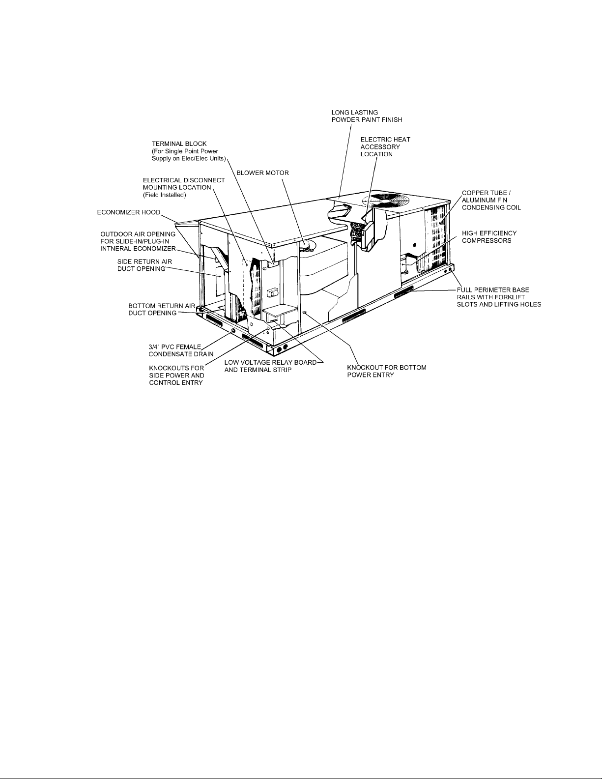
YORK Sunline 2000™ heat pumps are convertible single
package units with a common cabinet and a common roof
curb for the 3-6 ton sizes. The units were designed for light
commercial and commercial applications. They can easily be
installed on a roof curb, slab, roof jack or frame.
SINGLE PACKAGE HEAT PUMP UNITS
BP 036 thru 072
3 - 6 NOMINAL TONS
HIGH EFFICIENCY
All units include:
• Powder Paint finish that meets ASTM-B-117 1000 hour
salt spray standards
• Permanently lubricated motors
• Bottom or side air discharge configuration capability
(field convertible)
• Manufactured under the quality standards of ISO9001
®
• Simplicity
• Copper tube/aluminum fin coils
• Easy access to all components
• Rigging holes in base rails for lifting
• Fork lift slots on three sides
• Single point power connection
• Complete factory package - tested, charged and wired
• CSA agency listing on all units
WARRANTY
• Factory Limited Parts Warranty
• One-year parts warranty
Control Board
• A Five-year parts warranty on the compressor and
electric heat elements.
FOR DISTRIBUTION USE ONLY - NOT TO BE USED AT POINT OF RETAIL SALE
Page 2

TABLE OF CONTENTS
255027-YTG-B-0507
DESCRIPTION . . . . . . . . . . . . . . . . . . . . . . . . . . . . . 1
PRODUCT NOMENCLATURE . . . . . . . . . . . . . . . . . 3
FEATURES . . . . . . . . . . . . . . . . . . . . . . . . . . . . . . . . 4
FACTORY-INSTALLED OPTIONS . . . . . . . . . . . . . . 5
FIELD-INSTALLED ACCESSORIES . . . . . . . . . . . . 6
GUIDE SPECIFICATIONS . . . . . . . . . . . . . . . . . . . 40
LIST OF FIGURES
Fig. # Pg. #
1 UNIT CUTAWAY . . . . . . . . . . . . . . . . . . . . . . . . . . . . . .5
2 TYPICAL FIELD POWER & CONTROL WIRING . . . .34
3 UNIT DIMENSIONS - FRONT VIEW . . . . . . . . . . . . . .35
4 UNIT WITH ECONOMIZER RAINHOOD . . . . . . . . . . .35
5 UNIT WITH FIXED OUTDOOR AIR/MOTORIZED
DAMPER RAINHOOD . . . . . . . . . . . . . . . . . . . . . . . . .36
6 UNIT DIMENSIONS (REAR VIEW) . . . . . . . . . . . . . . .36
7 DISCONNECT/BLOWER ACCESS LOCATION . . . . . 37
8 TYPICAL APPLICATIONS . . . . . . . . . . . . . . . . . . . . . .38
9 FOUR AND SIX POINT LOADING . . . . . . . . . . . . . . . .39
10 ROOF CURB DIMENSIONS . . . . . . . . . . . . . . . . . . . .40
LIST OF TABLES
Tbl. # Pg. #
1 SOUND POWER RATING . . . . . . . . . . . . . . . . . . . . . . .7
2 CAPACITY RATING . . . . . . . . . . . . . . . . . . . . . . . . . . . .7
3 BP036 COOLING CAPACITIES (3 TON) . . . . . . . . . . . .8
4 BP048 COOLING CAPACITIES (4 TON) . . . . . . . . . . . .9
5 BP060 COOLING CAPACITIES (5 TON) . . . . . . . . . . .11
6 BP072 COOLING CAPACITIES (6 TON) . . . . . . . . . . .12
7 BP036-072 HEATING CAPACITIES . . . . . . . . . . . . . . 14
8 SUPPLY AIR BLOWER PERFORMANCE (BP036
BELT DRIVE) - SIDE DUCT APPLICATION . . . . . . . . 1 5
9 SUPPLY AIR BLOWER PERFORMANCE (BP036
BELT DRIVE) - BOTTOM DUCT APPLICATION . . . . . 16
Tbl. #
10 SUPPLY AIR BLOWER PERFORMANCE (BP048
BELT DRIVE) - SIDE DUCT APPLICATION . . . . . . . . 17
11 SUPPLY AIR BLOWER PERFORMANCE (BP048
BELT DRIVE) - BOTTOM DUCT APPLICATION . . . . 18
12 SUPPLY AIR BLOWER PERFORMANCE (BP060
BELT DRIVE) - SIDE DUCT APPLICATION . . . . . . . . 19
13 SUPPLY AIR BLOWER PERFORMANCE (BP060
BELT DRIVE) - BOTTOM DUCT APPLICATION . . . . 20
14 SUPPLY AIR BLOWER PERFORMANCE (BP072
BELT DRIVE) - SIDE DUCT APPLICATION . . . . . . . . 21
15 SUPPLY AIR BLOWER PERFORMANCE (BP072
BELT DRIVE) - BOTTOM DUCT APPLICATION . . . . 22
16 SUPPLY AIR BLOWER PERFORMANCE (BP036,
048, 060 & 072 DIRECT DRIVE) - SIDE FLOW
APPLICATION . . . . . . . . . . . . . . . . . . . . . . . . . . . . . . . 23
17 SUPPLY AIR BLOWER PERFORMANCE (BP036,
048, 060 & 072 DIRECT DRIVE) - BOTTOM FLOW
APPLICATION . . . . . . . . . . . . . . . . . . . . . . . . . . . . . . . 23
18 BELT DRIVE BLOWER MOTOR AND DRIVE DATA. . 24
19 STATIC RESISTANCES . . . . . . . . . . . . . . . . . . . . . . . 24
20 ELECTRIC HEATER CFM LIMITATIONS . . . . . . . . . . 24
21 ELECTRICAL DATA - BP036-072 DIRECT DRIVE W/O
POWERED CONVENIENCE OUTLET . . . . . . . . . . . . 25
22 ELECTRICAL DATA - BP036-072 BELT DRIVE W/O
POWERED CONVENIENCE OUTLET . . . . . . . . . . . . 27
23 ELECTRICAL DATA - BP036-072 DIRECT DRIVE W/
POWERED CONVENIENCE OUTLET . . . . . . . . . . . . 29
24 ELECTRICAL DATA - BP036-072 BELT DRIVE W/
POWERED CONVENIENCE OUTLET . . . . . . . . . . . . 31
25 PHYSICAL DATA . . . . . . . . . . . . . . . . . . . . . . . . . . . . 33
26 ELECTRIC HEAT CORRECTION FACTORS . . . . . . . 33
27 VOLTAGE LIMITATIONS . . . . . . . . . . . . . . . . . . . . . . 33
28 UTILITIES ENTRY . . . . . . . . . . . . . . . . . . . . . . . . . . . . 37
29 MINIMUM CLEARANCES . . . . . . . . . . . . . . . . . . . . . . 37
30 OPERATING WEIGHTS (LBS.) . . . . . . . . . . . . . . . . . . 39
Pg. #
2 Unitary Products Group
Page 3
255027-YTG-B-0507
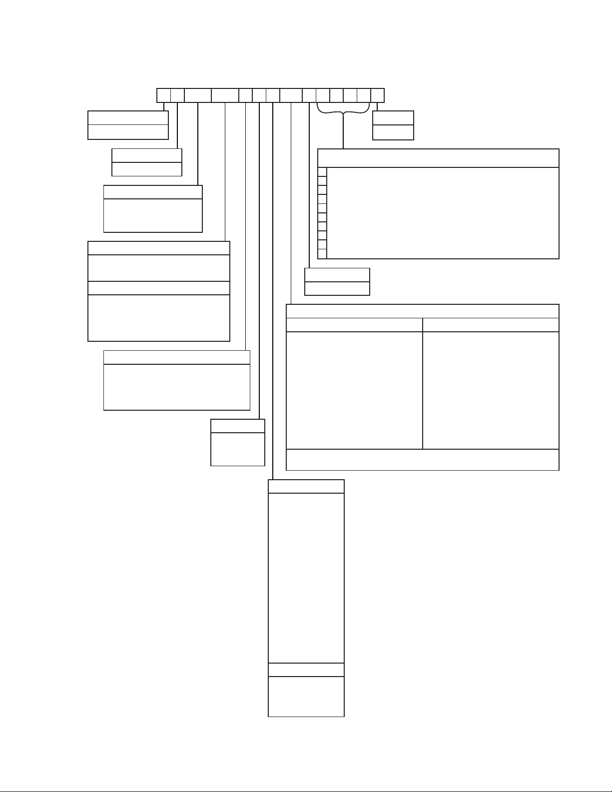
PRODUCT NOMENCLATURE
B P 048 C00 A 2 A AA 1 0 1 2 4 A
Product Category
B=HP,SinglePkg.,R-22
Product Identifier
P = 13.0 SEER HP
Nominal Cooling Capacity
036 = 3.0 Ton
048 = 4.0 Ton
060 = 5.0 Ton
072 = 6.0 Ton
Heat Type and Nominal Heat Capacity
C00 = Cooling Only. Suitable for Field
Installed Electric Heat
Electric Heat Options
E05 = 5 KW
E07 = 7 KW
E10 = 10 KW
E15 = 15 KW
E20 = 20 KW
E30 = 30 KW
Airflow
A = Direct Drive
B = Direct Drive/Single Input Economizer
D = Direct Drive/Motorized Damper
N = Belt Drive
P = Belt Drive/Single Input Economizer
R = Belt Drive/Motorized Damper
Voltage
1 = 208/230-1-60
2 = 208/230-3-60
4 = 460-3-60
5 = 575-3-60
Product Style
A = Style A
These four digits will not be assigned until a quote is requested, or an order placed.
SS Drain Pan
CPC Controller, DFS, APS
Johnson Controller, DFS, APS
Honeywell Controller, DFS, APS
Novar Controller, DFS, APS
Simplicity IntelliComfort Controller
Simplicity IntelliComfort Controller w/ModLinc
2" Pleated filters
BAS Ready Economizer (2-10 V.D.C. Actuator without a Controller)
Any Combination of Additional Options that Don’t Have an Option Code Pre-assigned
Product Generation
1 = First Generation
Standard Cabinet
AA = None
AB = Phase Monitor
AC = Coil Guard
AD = Dirty Filter Switch
AE = Phase Monitor & Coil Guard
AF = Phase Monitor & Dirty Filter Switch
AG = Coil Guard & Dirty Filter Switch
AH = Phase Monitor, Coil Guard & Dirty Filter Switch
AS = Bottom Drain Connection
RC = Coil Guard & American Flag
TA = Technicoat Condenser Coil
TJ = Technicoat Evaporator Coil
TS = Technicoat Evaporator and Condenser Coil
ZZ = If desired option combination is not listed above, ZZ will be assigned and configuration options will be
located in digits 15-18.
Configuration Options (not required for all units)
Additional Options
Hinged Filter Door & Toolless Access Cabinet
BA = Hinged Filter Door & Toolless Access Panels
BB = Phase Monitor, Hinged Filter Door & Toolless
Access Panels
BC = Coil Guard, Hinged Filter Door & Toolless
Access Panels
BD = Dirty Filter Switch, Hinged Filter Door &
Toolless Access Panels
BE = Phase Monitor & Coil Guard, Hinged Filter
Door & Toolless Access Panels
BF = Phase Monitor & Dirty Filter Switch, Hinged
Filter Door & Toolless Access Panels
BG = Coil Guard & Dirty Filter Switch, Hinged Filter
Door & Toolless Access Panels
BH = Phase Monitor, Coil Guard & Dirty Filter Switch,
Hinged Filter Door & Toolless Access Panels
Installation Options
A = No Options Installed
B=Option1
C=Option2
D = Options 1 & 2
E=Option3
F = Option 4
G = Options 1 & 3
H = Options 1 & 4
J = Options 1, 2 & 3
K = Options 1, 2, & 4
L = Options 1,3 & 4
M = Options 1, 2, 3, & 4
N = Options 2 & 3
P = Options 2 & 4
Q = Options 2, 3, & 4
R = Options 3 & 4
S=Option5
T = Options 1 & 5
U = Options 1, 3, & 5
V = Options 1, 4, & 5
W = Options 1, 3, 4, & 5
X = Options 3 & 5
Y = Options 4 & 5
Z = Options 3, 4 & 5
Options
1 = Disconnect
2 = Non-Pwr'd Conv. Outlet
3 = Smoke Detector S.A.
4 = Smoke Detector R.A.
5=Pwr'dConv.Outlet
Unitary Products Group 3
Page 4

255027-YTG-B-0507
FEATURES
All models are available with a wide variety of factorymounted options such as electric heaters, phase monitor,
convenience outlet, dirty filter switch, disconnect switch,
smoke detectors, and coil guards to make them suitable for
almost every application.
All units are self-contained and assembled on full perimeter
base rails with forklift holes on three sides and holes for overhead rigging. Every unit is completely piped, wired, charged
and tested at the factory to simplify the field installation and to
provide years of dependable operation.
All models (including those with an economizer) are suitable
for either bottom or horizontal duct connections. For bottom
duct, remove the sheet metal panels from the supply and
return air openings through the base of the unit. For horizontal duct, remove the supply and return air panels on the rear
of the unit.
All models are available with these “factory mounted” outdoor
air damper options:
• Single enthalpy economizer
• Motorized outdoor air damper
Supply air blowers are equipped with either direct drive or
belt drive that can be adjusted to meet the exact requirements of the job.
All compressors are equipped with internal pressure relief.
Every refrigerant circuit includes a liquid line filter-drier, a high
pressure switch and a suction line with a freezestat and low
pressure/loss of charge switch to protect all system components.
®
• Simplicity
standardized a number of features previously available
only as options or by utilizing additional controls.
• Low Ambient - An integrated low-ambient control
• Anti-Short Cycle Protection - To aid compressor
Controls - Simplicity® control boards have
allows all units to operate in the cooling mode down
to 0ºF outdoor ambient without additional assistance. Optionally , the control board can be programmed to lockout the compressors when the
outdoor air temperature is low or when free cooling
is available.
life, an anti-short cycle delay is incorporated into the
standard controls. Compressor reliability is further
ensured by programmable minimum run times. For
testing, the anti short cycle delay can be temporarily
overridden with the push of a button.
• Fan Delays - Fan on and fan off delays are fully programmable and are independent of one another. All
units are programmed with default values based
upon their configuration of cooling and heat.
• Safety Monitoring - The control board monitors the
high and low-pressure switches, the freezestats, the
gas valve, if applicable, and the temperature limit
switch on gas heat units. The unit control board will
alarm on ignition failures, compressor lockouts and
repeated limit switch trips.
• Nuisance Trip Protection- To prevent nuisance
trouble calls, the control board uses a “three strikes,
you’re out” philosophy. The high and low-pressure
switches and the freezestats must trip three times
within two hours before the unit control board will
lock out the compressor.
• On Board Diagnostics - Each alarm will energize a
trouble light on the thermostat, if so equipped, and
flash an alarm code on the control board LED. Each
high and low-pressure switch alarm as well as each
freezestat alarm has its own flash code. The control
board saves the five most recent alarms in memory,
and these alarms can be reviewed at any time.
Alarms and programmed values are retained
through the loss of power.
All units have long lasting powder paint cabinets with 1000
hour salt spray test approval under ASTM-B117 procedures.
All models are CSA listed.
• Warranty - All models include a one-year limited parts
warranty on the complete unit. Compressors and electric
heater elements carry a five-year warranty
• Electric Heat Operation - All electric heat models are
wired for a single power source and include a bank of
nickel chromium elements mounted at the discharge of
the supply air blower to provide a high velocity and uniform distribution of air across the heating elements.
Every element is fully protected against excessive temperature by thermal limit switches.
The power supply wiring can be routed into the control
box through a threaded pipe connection (field supplied)
in the base pan of the unit or through a knockout in the
wiring panel on the side of the unit.
• BAS Controls - York’s Sunline™ series units offer factory mounted BAS controls such as Simplicity
®
INTELLI-
Comfort™, Novar, Honeywell, Johnson, and CPC.
4 Unitary Products Group
Page 5
255027-YTG-B-0507
FIGURE 1 - UNIT CUTAWAY
FACTORY-INSTALLED OPTIONS
• SINGLE INPUT ELECTRONIC ENTHALPY ECONOMIZERS - Includes a slide-in / plug-in damper assembly
with fully modulating spring-return motor actuator capable of introducing up to 100% outdoor air with nominal
1% leakage type dampers.
The enthalpy system contains one sensor that monitors
the outdoor air and determines when the air is cool
enough and dry enough to provide free cooling.
The rainhood is painted to match the basic unit and must
be field-assembled before installing.
• MOTORIZED OUTDOOR AIR INTAKE DAMPER -
Includes a slide-in / plug-in damper assembly with a 2position, spring return motor actuator which opens to a
pre-set position whenever the supply air blower is operating and will drive fully closed when the blower unit
shuts down.
The rain hood is painted to match the basic unit and
must be field assembled before installing.
• PHENOLIC COATED EVAPORATOR AND CON-
DENSER COILS - Special coating process that utilizes
Technicoat 10-1
immersion of the complete coil for maximum protection.
TM
processes. Coating is applied by total
• ELECTRIC HEATERS - Wired for single point power
supply. These nickel chromium heater elements are provided with limit and automatic reset capability to prevent
operation at excessive temperatures.
• FILTER OPTIONS - Standard units are shipped with 1”
throw-away filters installed. 2” pleated filters are offered
as a factory installed option.
• CONVENIENCE OUTLET - This 110 volt outlet can be
“powered” by the unit with a stepdown transformer or the
unit may be ordered with a “non-powered” convenience
outlet that can be wired in the field.
• DISCONNECT SWITCH - For heat pump units with electric heat, an HACR breaker sized to the unit is provided.
For heat pump units without electric heat, a switch sized
to the largest electric heat available for the particular unit
is provided. Factory-installed option only.
• BAS - Building Automation System Controls
Simplicity
®
INTELLI-Comfort™ CONTROL - The Y ork®
Simplicity® INTELLI-Comfort™ control is factory installed.
It includes a supply air sensor, a return air sensor, and an
outside air sensor . There are provisions for a field installed
dirty filter indicator switch, an air-proving switch, an Outside Air Humidity sensor, a Return Air Humidity sensor , an
Inside IAQ sensor, and an Outside Ai r IAQ sensor. Construction mode operation, 365-day real time clock with 7
Unitary Products Group 5
Page 6

255027-YTG-B-0507
day programming plus holiday scheduling is built-in. Two
different modes of demand ventilation are achieved
through the INTELLI-Comfort™using CO2 sensors. It
uses an inside CO
sensor to perform Demand Ventila-
2
tion. It can also use an Outside CO2 sensor to perform
Differential Demand V entilati on. It uses a Pate nted Comfort Ventilation al gorithm to provide comfortab le ventilation
air temperature. The patented economizer-loading algorithm will protect the equipment when harsh operating
conditions exist. Humidity in the occupied space or return
duct can be monitored and controlled via humidity sensors
and the on-board connection for hot gas re-heat system.
It uses the INTELLI-Start™ alg orithm to maximize energy
savings by recovering the building from the Unoccupied
Setpoints to the Occupied Setpoints just in time for the
Occupied Time Period to begin. The Simplicity
®
INTELLIComfort™ balances space temperature, ventilation air
temperature, CO
• Simplicity
®
and humidity for ultimate comfort.
2
INTELLI-Comfort™ with ModLINC CON-
TROL - The York® Simplicity® INTELLI-Comfort™ with
ModLINC control is factory installed. It includes all the
features of the INTELLI-Comfort™ control with an additional control to translate communications from MODBUS to the BACnet MSTP protocol.
• Novar® BAS CONTROL - The Novar® ETC-3 building
automation system controller is factory installed.
Includes supply air sensor, return air sensor, dirty filter
indicator switch, and air proving switch.
• JOHNSON CONTROLS BAS CONTROL - The Johnson
Control YK-UNT-1126 building automation system controller is factory installed. Includes supply air sensor, return air
sensor, dirty filter indicator switch, and air proving switch.
• CPC BAS CONTROL - The Computer Process Controls
Model 810-3060 ARTC Advanced Rooftop building automation system controller is factory installed. Includes
supply air sensor, return air sensor, dirty filter indicator
switch and air proving switch.
• HONEYWELL BAS CONTROL - The Honeywell
W7750C building automation system controller is factory
installed. Includes air supply sensor, return air sensor,
dirty filter indicator switch, and air proving switch.
• SMOKE DETECTORS - (supply air & return air) The
smoke detectors stop operation of the unit by interrupting
power to the control board if smoke is detected within the
air compartment.
Factory installed Smoke Detectors in the Return
Air, may be subjected to freezing temperatures
during "off" times due to Out Side Air infiltration.
These Smoke Detectors have an operational limit
of 32°F to 131°F. Smoke Detectors installed in
areas that could be out side those limitations will
have to be moved to prevent having false alarms.
• STAINLESS STEEL DRAIN PAN - An optional rust-proof
stainless steel drain pan is available to provide years of
trouble-free operation in corrosive environments.
• BOTTOM DRAIN CONNECTION - An optional bottom
drain connection is available for inside the curb connections for applications in cold environments to reduce
freezing drain lines.
• COIL GUARD - Customers can purchase a coil guard kit
to protect the condenser coil from damage. This is not a
hail guard kit.
• PHASE MONITORS - Designed to prevent unit damage.
The phase monitor will shut the unit down in an out-ofphase condition.
• DIRTY FILTER SWITCH - This kit includes a differential
pressure switch that energizes the fault light on the unit
thermostat, indicating that there is an abnormally high
pressure drop across the filters. Factory installed option
or field installed accessory.
• HINGED FILTER DOOR/“TOOLLESS” BLOWER AND
ACCESS PANELS (not hinged) - This option allows for
easy access and maintenance.
NOTE:Knobs are shipped inside the unit to prevent ship-
ping damage. These must be field installed for
toolless operation.
FIELD-INSTALLED ACCESSORIES
• SINGLE INPUT ELECTRONIC ENTHALPY ECONOMIZERS - Includes a slide-in / plug-in damper assembly
with fully modulating spring-return motor actuator capable of introducing up to 100% outdoor air with nominal
1% leakage type dampers.
The enthalpy system contains one sensor that monitors
the outdoor air and determines when the air is cool
enough and dry enough to provide free cooling.
The rainhood is painted to match the basic unit and must
be field-assembled before installing.
• MOTORIZED OUTDOOR AIR INTAKE DAMPER -
Includes a slide-in / plug-in damper assembly with a 2position, spring return motor actuator which opens to
some pre-set position whenever the supply air blower is
operating and will drive fully closed when the blower unit
shuts down.
The rain hood is painted to match the basic unit and
must be field assembled before installing.
• ELECTRIC HEATERS wired for single point power sup-
ply. These nickel chromium heater elements are provided with limit and automatic reset capability to prevent
operation at excessive temperatures.
• ROOF CURBS - Eight and fourteen-inch high roof curbs
provide a water-tight seal between the unit and the finished
roof. These full perimeter curbs meet the requirements of
the National Roofing Contractors Association (NRCA) and
are shipped knocked-down for field assembly.
6 Unitary Products Group
Page 7
255027-YTG-B-0507
Roof curbs are designed to fit inside the base rails of the
unit and include both a wood nailing strip and duct
hanger supports.
• POWER EXHAUST - Our single input economizer
options are available with power exhaust. Whenever the
outdoor air intake dampers are opened for free cooling,
the exhaust fan will be energized to prevent the conditioned space from being over-pressurized during economizer operation.
The power exhaust option can only be used on bottom duct configurations.
• BAROMETRIC RELIEF DAMPER - This damper accessory can be used to relieve internal building air pressure
on units with an economizer without power exhaust. This
accessory includes a rain hood, a bird screen and a fully
assembled damper. With bottom duct connections, the
damper should be mounted over the opening in the
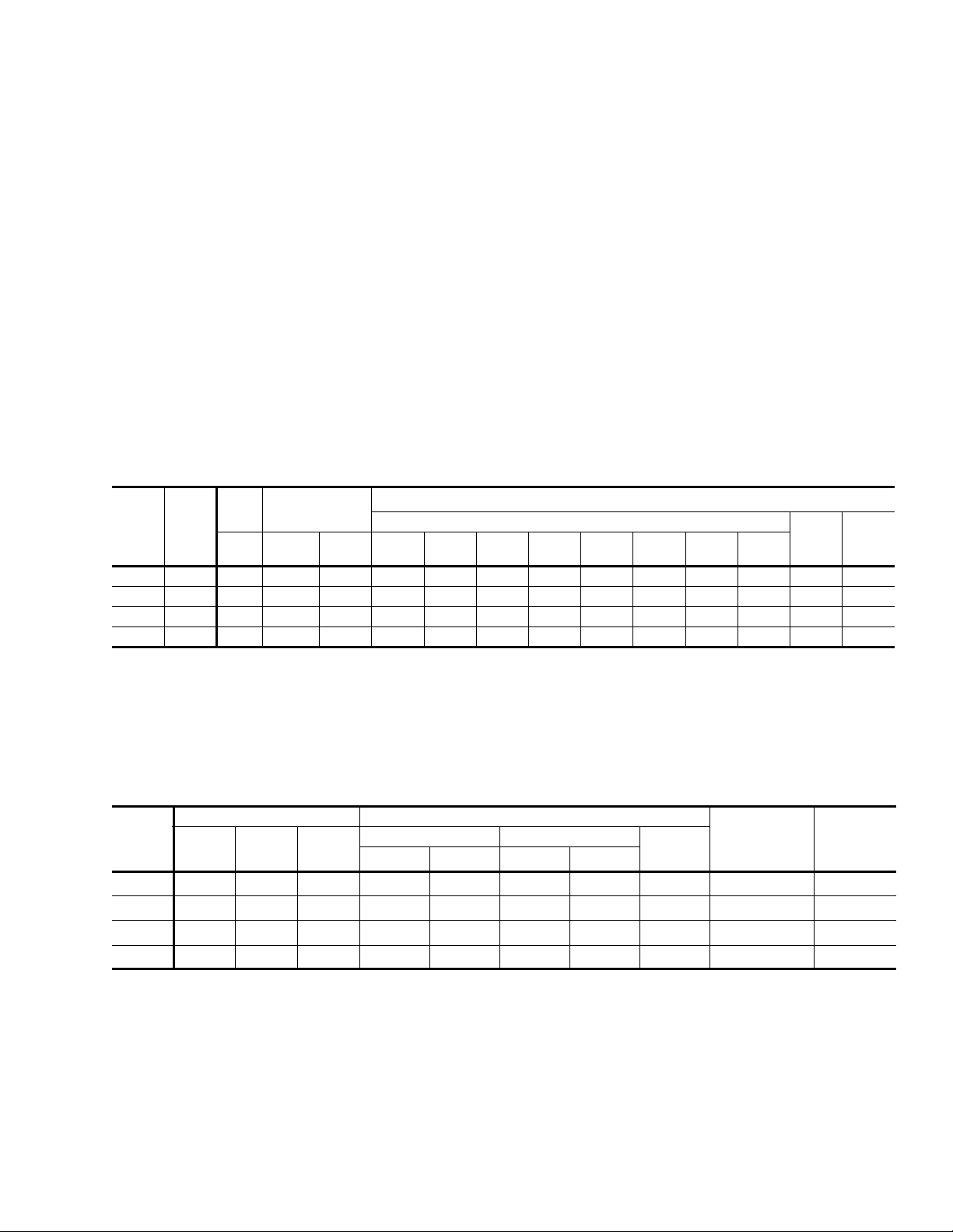
TABLE 1: SOUND POWER RATING
UNIT
SIZE
036 1,200 0.6 - 0.60 84 84 74 67 69 62 57 52 74 41
048 1,6000.55-0.8085857568706358537542
060 2,0000.45-1.0086867669716459547643
072 2,2000.30-1.3587877770726560557744
CFM
1. These values have been accessed using a model of sound propagation from a point source into the hemispheric\free field. The
dBA values provided are to be used for reference only. Calculation of dBA values cover matters of system design and the fan
manufacture has no way of knowing the details of each system. This constitutes and expectation to any specification or guarantee requiring a dBA value or sound data in any other form than sound power level ratings.
2. At a distance of 10 feet from the blower.
ESP BLOWER
IWG SPEED KW 63 125 250 500 1,000 2,000 4,000 8,000
1
Octave Band Centerline Frequency (Hz)
return air panel. With horizontal ductwork, the accessory
should be mounted on the return air duct.
• ENTHALPY ACCESSORY CONTROL KIT - This kit
contains the required components to convert a single
enthalpy economizer to dual enthalpy.
• BURGLAR BARS - Mount in the supply and return
openings to prevent entry into the duct work.
• CO
SENSOR - Senses CO2 levels and automatically
2
overrides the economizer when levels rise above the
present limits.
• COIL GUARD - Customers can purchase a coil guard kit
to protect the condenser coil from damage. This is not a
hail guard kit.
• HAIL GUARD - Hail guard is available to protect the unit
from hail damage. This is a sloped hood that fits above
the coil.
SOUND POWER (db 10
-12
Watts)
SWL
dB(A)
dB(A)
@
10Ft.
2
TABLE 2: CAPACITY RATING
COOLING PERFORMANCE HEATING PERFORMANCE
MODEL
036
048
060
072
1. Rated in accordance with ARI Standard 270.
2. EER = Energy Efficiency Ratio at full load - the ratio (expressed in Btuh/Watt) of the cooling capacity and total power.
3. SEER = Seasonal Energy Efficiency Ratio.
4. HSPF = Heating Seasonal Performance Factor. Based on Region IV minimum design heating requirement.
5. COP = Coefficient of Performance
6. Cooling and heating performance rated in accordance with ARI 210/240.
7. Cooling and heating performance rated in accordance with ARI 340/360.
Unitary Products Group 7
MBH
6
35.0 11.6 13.30 32.2 3.20 17.6 2.10 7.85 1200 84
6
46.5 11.1 13.15 44.0 3.40 23.2 2.10 7.75 1600 83
6
55.0 11.2 13.55 52.0 3.25 29.2 2.15 7.75 2000 81
7
68.0 10.2 - 69 3.20 43.0 2.20 - 2400 84
EER
2
SEER
3
47 °F 17 °F
MBH
COP
5
MBH
COP
HSPF
5
4
NOMINAL
CFM
SOUND
RATING
1
(Db)
Page 8

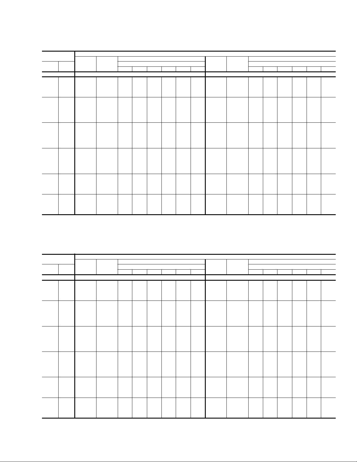
TABLE 3: BP036 COOLING CAPACITIES (3 TON)
Air on
Evaporator Coil
CFM
750
900
1050
1200
1350
1500
750
900
1050
1200
1350
1500
WB
(°F)
77 42.7 2.1 16.5 13.3 10.3 - - - 41.2 2.4 16.1 13.1 10.0 - - 72 39.8 2.1 22.0 19.0 16.1 13.1 - - 37.9 2.4 21.5 18.5 15.5 12.5 - 67 36.8 2.1 27.5 24.8 21.8 18.9 15.9 - 34.7 2.4 27.0 24.0 20.9 17.9 14.9 62 35.2 2.1 35.1 28.3 25.7 22.7 19.8 16.8 33.4 2.3 33.3 28.1 24.7 21.7 18.6 15.6
77 44.9 2.1 18.5 15.1 11.6 - - - 42.9 2.4 18.3 14.8 11.3 - - 72 41.7 2.1 24.9 21.5 18.1 14.7 - - 39.5 2.4 24.4 20.9 17.4 13.9 - 67 38.6 2.1 31.4 28.0 24.6 21.2 17.8 - 36.2 2.4 30.5 27.0 23.5 20.0 16.5 62 36.9 2.1 36.9 32.3 28.9 25.5 22.1 18.7 34.8 2.3 34.8 31.3 27.8 24.3 20.8 17.3
57 34.3 2.1 34.3 33.3 29.8 26.4 23.0 19.6 33.1 2.3 33.1 31.8 28.3 24.8 21.3 17.8
77 47.0 2.1 20.4 16.8 12.9 - - - 44.7 2.4 20.4 16.5 12.5 - - 72 43.7 2.1 27.9 24.0 20.1 16.3 - - 41.1 2.4 27.3 23.3 19.3 15.4 - 67 40.5 2.1 35.3 31.2 27.3 23.5 19.6 - 37.6 2.4 34.1 30.1 26.1 22.2 18.2 62 38.7 2.1 38.6 36.4 32.2 28.3 24.4 20.6 36.2 2.3 36.2 34.4 30.8 26.9 22.9 18.9
57 36.0 2.1 36.0 35.4 33.2 29.3 25.5 21.6 34.4 2.4 34.4 33.8 31.4 27.5 23.5 19.6
77 49.1 2.1 22.3 18.6 14.2 - - - 46.4 2.4 22.6 18.2 13.8 - - 72 45.7 2.1 30.8 26.5 22.2 17.8 - - 42.8 2.4 30.1 25.7 21.2 16.8 - 67 42.3 2.2 39.3 34.4 30.1 25.8 21.4 - 39.1 2.4 37.6 33.2 28.7 24.3 19.9 62 40.4 2.1 40.4 40.4 35.4 31.1 26.8 22.4 37.6 2.4 37.6 37.6 33.9 29.5 25.0 20.6
57 37.6 2.1 37.6 37.6 36.5 32.2 27.9 23.6 35.8 2.4 35.8 35.8 34.6 30.1 25.7 21.3
72 46.4 2.1 32.8 28.0 23.1 18.3 - - 43.4 2.4 32.1 27.2 22.3 17.4 - 67 42.9 2.1 41.4 36.2 31.4 26.6 21.8 - 39.7 2.4 39.0 35.0 30.1 25.2 20.3 62 41.0 2.1 41.0 41.0 37.0 32.2 27.3 22.5 38.2 2.4 38.2 38.2 35.5 30.6 25.7 20.8
57 38.2 2.1 38.2 38.2 37.6 32.8 28.0 23.2 36.4 2.4 36.4 36.4 35.7 30.8 25.9 21.0
72 47.1 2.1 34.8 29.5 24.1 18.8 - - 44.1 2.4 34.1 28.7 23.3 17.9 - 67 43.6 2.1 43.6 38.1 32.8 27.4 22.1 - 40.3 2.4 40.3 36.9 31.5 26.1 20.7 62 41.7 2.1 41.7 41.7 38.6 33.2 27.9 22.6 38.8 2.4 38.8 38.8 37.1 31.8 26.4 21.0
57 38.8 2.1 38.8 38.8 38.8 33.4 28.1 22.8 36.9 2.4 36.9 36.9 36.9 31.5 26.1 20.7
77 39.6 2.6 15.6 12.8 9.7 - - - 36.1 2.9 13.5 11.7 8.5 - - 72 36.1 2.6 21.1 18.0 14.9 11.8 - - 33.0 2.8 20.1 16.9 13.7 10.5 - 67 32.6 2.6 26.5 23.1 20.0 17.0 13.9 - 29.9 2.8 26.7 22.1 18.9 15.7 12.5 62 31.6 2.5 31.6 27.8 23.7 20.6 17.5 14.4 29.1 2.8 29.1 26.2 21.7 18.5 15.2 12.0
77 41.0 2.7 18.1 14.5 10.9 - - - 37.3 2.9 17.0 13.2 9.5 - - 72 37.3 2.6 23.9 20.3 16.7 13.1 - - 34.1 2.9 22.9 19.2 15.4 11.7 - 67 33.7 2.6 29.7 26.1 22.5 18.9 15.3 - 30.9 2.8 28.8 25.1 21.4 17.6 13.9 62 32.7 2.6 32.7 30.2 26.6 23.0 19.4 15.8 30.1 2.8 30.1 28.1 24.4 20.7 17.0 13.3
57 31.9 2.6 31.9 30.4 26.8 23.2 19.6 16.0 28.9 2.8 28.9 28.2 24.6 20.9 17.2 13.5
77 42.3 2.7 20.5 16.1 12.1 - - - 38.5 2.9 20.4 14.8 10.6 - - 72 38.6 2.6 26.6 22.6 18.5 14.5 - - 35.2 2.9 25.6 21.4 17.2 13.0 - 67 34.8 2.6 32.8 29.0 25.0 20.9 16.8 - 31.9 2.8 30.9 28.0 23.8 19.6 15.3 62 33.7 2.6 33.7 32.5 29.5 25.4 21.4 17.3 31.1 2.8 31.1 30.1 27.2 23.0 18.8 14.6
57 32.9 2.6 32.9 32.2 29.7 25.6 21.6 17.5 29.9 2.8 29.9 29.5 27.4 23.2 18.9 14.7
77 43.7 2.7 22.9 17.8 13.3 - - - 39.8 2.9 23.8 16.4 11.7 - - 72 39.8 2.6 29.4 24.9 20.3 15.8 - - 36.3 2.9 28.4 23.6 18.9 14.2 - 67 35.9 2.6 35.9 32.0 27.4 22.9 18.3 - 32.9 2.9 32.9 30.9 26.2 21.5 16.8 62 34.8 2.6 34.8 34.8 32.4 27.8 23.3 18.7 32.1 2.8 32.1 32.1 30.0 25.3 20.5 15.8
57 34.0 2.6 34.0 34.0 32.6 28.1 23.5 19.0 30.9 2.8 30.9 30.9 30.2 25.4 20.7 16.0
72 40.4 2.7 31.4 26.4 21.4 16.4 - - 36.8 2.9 30.2 25.1 19.9 14.8 - 67 36.5 2.6 36.5 33.8 28.8 23.8 18.8 - 33.3 2.9 33.3 32.0 27.5 22.4 17.2 62 35.4 2.6 35.4 35.4 34.0 29.1 24.1 19.1 32.5 2.8 32.5 32.5 31.4 26.2 21.1 15.9
57 34.5 2.6 34.5 34.5 33.8 28.8 23.9 18.9 31.2 2.8 31.2 31.2 30.9 25.7 20.5 15.4
72 41.1 2.7 33.3 27.9 22.4 17.0 - - 37.2 2.9 32.1 26.5 20.9 15.3 - 67 37.0 2.6 37.0 35.7 30.2 24.8 19.3 - 33.7 2.9 33.7 33.0 28.9 23.3 17.7 62 35.9 2.6 35.9 35.9 35.7 30.3 24.8 19.4 32.9 2.8 32.9 32.9 32.8 27.2 21.6 16.0
57 35.1 2.6 35.1 35.1 35.1 29.6 24.2 18.7 31.6 2.8 31.6 31.6 31.6 26.0 20.4 14.8
Total
Capacity
(MBh)
Total
1
Input
2
(kW)
Sensible Capacity (MBh)
Return Dry Bulb (°F) Return Dry Bulb (°F)
90 85 80 75 70 65 90 85 80 75 70 65
75°F 85°F
95°F 105°F
Temperature of Air on Condenser Coil
Total
Capacity
(MBh)
255027-YTG-B-0507
Total
1
Input
2
(kW)
Sensible Capacity (MBh)
8 Unitary Products Group
Page 9
255027-YTG-B-0507
TABLE 3: BP036 COOLING CAPACITIES (3 TON) (CONT.)
Air on
Evaporator Coil
CFM
750
900
1050
1200
1350
1500
WB
(°F)
77 32.5 3.1 11.4 10.5 7.2 - - - 29.0 3.3 11.9 8.4 5.9 - - 72 29.8 3.1 19.1 15.8 12.5 9.2 - - 26.7 3.3 18.2 14.7 11.3 7.9 - 67 27.2 3.0 26.9 21.1 17.8 14.5 11.2 - 24.5 3.3 24.5 20.1 16.7 13.3 9.8 62 26.7 3.0 26.7 24.5 19.7 16.3 13.0 9.7 24.3 3.2 24.3 22.8 17.6 14.2 10.8 7.3
77 33.6 3.1 15.8 12.0 8.2 - - - 29.9 3.3 16.4 10.8 6.8 - - 72 30.9 3.1 21.9 18.0 14.2 10.3 - - 27.6 3.3 20.9 16.9 12.9 8.9 - 67 28.1 3.1 27.9 24.0 20.2 16.4 12.5 - 25.3 3.3 25.3 23.0 19.0 15.1 11.1 62 27.6 3.0 27.6 26.1 22.3 18.4 14.6 10.8 25.1 3.2 25.1 24.1 20.1 16.2 12.2 8.2
57 26.0 3.0 26.0 26.0 22.4 18.5 14.7 10.9 23.1 3.2 23.1 23.1 20.2 16.2 12.2 8.3
77 34.7 3.1 20.2 13.5 9.1 - - - 30.9 3.4 21.0 13.1 7.6 - - 72 31.9 3.1 24.6 20.2 15.9 11.5 - - 28.5 3.3 23.5 19.0 14.5 10.0 - 67 29.0 3.1 28.9 26.9 22.6 18.2 13.9 - 26.1 3.3 26.1 25.9 21.4 16.9 12.4 62 28.5 3.0 28.5 27.8 24.9 20.6 16.2 11.8 25.9 3.3 25.9 25.4 22.6 18.1 13.6 9.1
57 26.9 3.0 26.9 26.9 25.0 20.7 16.3 12.0 23.8 3.3 23.8 23.8 22.7 18.2 13.7 9.2
77 35.8 3.2 24.6 15.0 10.1 - - - 31.9 3.4 25.5 15.4 8.5 - - 72 32.9 3.1 27.3 22.4 17.5 12.6 - - 29.4 3.4 26.2 21.2 16.1 11.1 - 67 29.9 3.1 29.9 29.9 25.0 20.1 15.2 - 27.0 3.3 27.0 27.0 23.8 18.7 13.7 62 29.4 3.1 29.4 29.4 27.6 22.7 17.8 12.9 26.7 3.3 26.7 26.7 25.1 20.1 15.0 10.0
57 27.7 3.1 27.7 27.7 27.7 22.8 17.9 13.0 24.6 3.3 24.6 24.6 24.6 20.2 15.1 10.1
72 33.1 3.1 29.1 23.8 18.4 13.1 - - 29.5 3.4 27.9 22.4 17.0 11.5 - 67 30.1 3.1 30.1 30.1 26.3 20.9 15.6 - 27.0 3.4 27.0 27.0 25.0 19.5 14.0 62 29.6 3.1 29.6 29.6 28.7 23.4 18.1 12.7 26.8 3.3 26.8 26.8 26.0 20.5 15.1 9.6
57 27.9 3.1 27.9 27.9 27.9 22.6 17.2 11.9 24.6 3.3 24.6 24.6 24.6 19.4 13.9 8.5
72 33.3 3.2 30.9 25.1 19.3 13.6 - - 29.5 3.4 29.5 23.7 17.8 11.9 - 67 30.4 3.1 30.4 30.4 27.6 21.8 16.0 - 27.0 3.4 27.0 27.0 26.2 20.3 14.4 62 29.8 3.1 29.8 29.8 29.8 24.1 18.3 12.6 26.8 3.3 26.8 26.8 26.8 21.0 15.1 9.2
57 28.1 3.1 28.1 28.1 28.1 22.3 16.6 10.8 24.6 3.3 24.6 24.6 24.6 18.7 12.8 6.9
Total
Capacity
(MBh)
Total
1
Input
2
(kW)
Sensible Capacity (MBh)
Return Dry Bulb (°F) Return Dry Bulb (°F)
90 85 80 75 70 65 90 85 80 75 70 65
115°F 125°F
1. These capacities are gross ratings. For net capacity, deduct air blower motor, MBh = 3.415 x kW. Refer to the appropriate Blower
Performance Table for the kW of the supply air blower motor.
2. These ratings include the condenser fan motors (total 1 kW) and the compressor motors but not the supply air blower motor.
Temperature of Air on Condenser Coil
Total
Capacity
(MBh)
Total
1
Input
(kW)
Sensible Capacity (MBh)
2
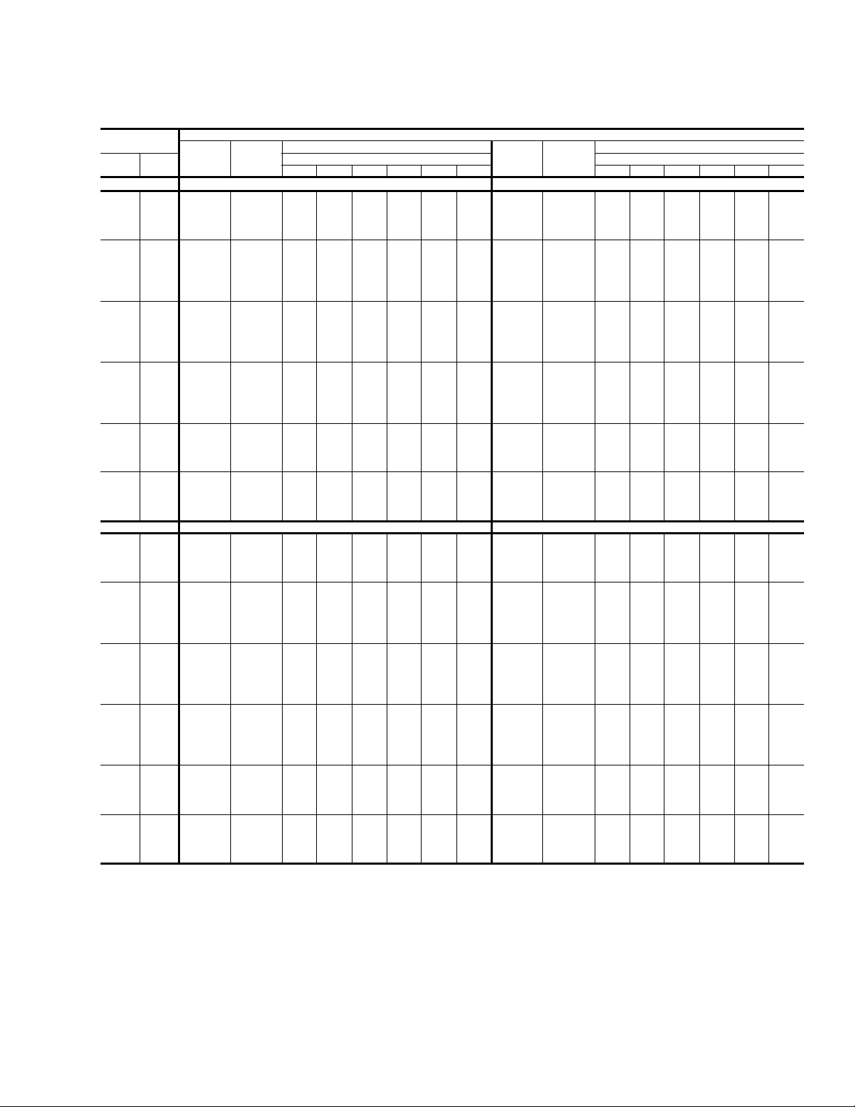
TABLE 4: BP048 COOLING CAPACITIES (4 TON)
Air on
Evaporator Coil
CFM
1000
1200
1400
1600
1800
2000
WB
(°F)
77 61.2 3.0 23.7 19.8 15.9 - - - 56.9 3.3 22.8 18.8 14.8 - - 72 55.6 3.0 30.4 26.6 22.7 18.8 - - 51.5 3.3 29.3 25.3 21.3 17.3 - 67 50.0 3.0 37.2 33.3 29.4 25.5 21.6 - 46.1 3.3 35.9 31.9 27.9 23.9 19.9 62 44.8 2.9 44.8 41.4 35.4 31.6 27.7 23.8 41.4 3.2 41.4 39.7 34.0 30.0 26.0 22.0
77 63.8 3.0 26.8 22.2 17.6 - - - 59.4 3.4 25.6 21.0 16.3 - - 72 57.9 3.0 34.2 29.7 25.1 20.5 - - 53.8 3.3 32.9 28.2 23.6 18.9 - 67 52.1 3.0 41.7 37.1 32.5 27.9 23.3 - 48.1 3.3 40.1 35.5 30.8 26.2 21.5 62 46.7 2.9 46.7 44.5 39.2 34.6 30.0 25.4 43.2 3.2 43.2 42.1 37.5 32.8 28.1 23.5
57 46.4 2.9 46.4 46.4 41.5 36.9 32.3 27.7 43.4 3.2 43.4 43.4 39.0 34.3 29.7 25.0
77 66.4 3.0 29.9 24.6 19.3 - - - 61.9 3.4 28.5 23.2 17.8 - - 72 60.3 3.0 38.1 32.8 27.5 22.2 - - 56.0 3.3 36.4 31.1 25.8 20.4 - 67 54.2 3.0 46.2 40.9 35.6 30.3 25.1 - 50.2 3.3 44.4 39.0 33.7 28.4 23.1 62 48.6 3.0 48.6 47.5 43.0 37.7 32.4 27.1 45.1 3.2 45.1 44.5 41.0 35.7 30.3 25.0
57 48.2 2.9 48.2 48.2 45.4 40.2 34.9 29.6 45.3 3.2 45.3 45.3 42.7 37.3 32.0 26.7
77 69.0 3.0 33.0 27.0 21.0 - - - 64.4 3.4 31.3 25.4 19.4 - - 72 62.7 3.0 41.9 35.9 29.9 23.9 - - 58.3 3.3 40.0 34.0 28.0 22.0 - 67 56.3 3.0 50.8 44.8 38.8 32.8 26.8 - 52.2 3.3 48.6 42.6 36.6 30.6 24.6 62 50.5 3.0 50.5 50.5 46.7 40.7 34.7 28.7 46.9 3.3 46.9 46.9 44.5 38.5 32.5 26.5
57 50.1 3.0 50.1 50.1 49.4 43.4 37.4 31.4 47.1 3.2 47.1 47.1 46.3 40.4 34.4 28.4
72 64.5 3.0 45.4 38.8 32.2 25.6 - - 59.9 3.4 43.3 36.7 30.1 23.5 - 67 58.0 3.0 55.2 48.4 41.8 35.2 28.6 - 53.6 3.3 51.8 46.0 39.4 32.8 26.2 62 52.0 3.0 52.0 52.0 50.1 43.5 36.9 30.3 48.2 3.3 48.2 48.2 47.0 40.4 33.8 27.2
57 51.6 3.0 51.6 51.6 51.3 44.7 38.1 31.5 48.4 3.3 48.4 48.4 48.0 41.4 34.8 28.2
72 66.4 3.0 48.9 41.7 34.5 27.3 - - 61.5 3.4 46.6 39.4 32.2 25.0 - 67 59.7 3.0 59.7 52.0 44.8 37.6 30.4 - 55.1 3.3 55.1 49.3 42.1 34.9 27.8 62 53.5 3.0 53.5 53.5 53.5 46.3 39.1 31.9 49.5 3.3 49.5 49.5 49.5 42.3 35.1 27.9
57 53.2 3.0 53.2 53.2 53.2 45.9 38.7 31.5 49.7 3.3 49.7 49.7 49.7 42.5 35.3 28.1
Total
Capacity
(MBh)
Total
1
Input
2
(kW)
Sensible Capacity (MBh)
Return Dry Bulb (°F) Return Dry Bulb (°F)
90 85 80 75 70 65 90 85 80 75 70 65
75°F 85°F
Temperature of Air on Condenser Coil
Total
Capacity
(MBh)
Total
1
Input
2
(kW)
Sensible Capacity (MBh)
Unitary Products Group 9
Page 10

255027-YTG-B-0507
TABLE 4: BP048 COOLING CAPACITIES (4 TON) (CONT.)
Air on
Evaporator Coil
CFM
1000
1200
1400
1600
1800
2000
1000
1200
1400
1600
1800
2000
WB
(°F)
77 52.5 3.7 21.8 17.7 13.6 - - - 48.5 4.0 19.2 15.9 11.9 - - 72 47.4 3.6 28.2 24.1 20.0 15.9 - - 43.6 3.9 26.5 22.4 18.3 14.2 - 67 42.3 3.6 34.6 30.5 26.4 22.3 18.2 - 38.6 3.8 33.8 28.8 24.7 20.7 16.6 62 38.1 3.5 38.1 38.1 32.5 28.3 24.2 20.1 34.8 3.8 34.8 34.8 29.6 25.6 21.5 17.4
77 54.9 3.7 24.5 19.7 15.0 - - - 50.7 4.1 22.6 17.8 13.1 - - 72 49.6 3.7 31.5 26.8 22.0 17.3 - - 45.5 4.0 29.7 24.9 20.2 15.5 - 67 44.2 3.6 38.6 33.8 29.1 24.4 19.6 - 40.3 3.9 36.8 32.1 27.3 22.6 17.8 62 39.8 3.5 39.8 39.8 35.7 31.0 26.3 21.5 36.3 3.8 36.3 36.3 32.7 28.0 23.2 18.5
57 40.5 3.5 40.5 40.5 36.5 31.8 27.1 22.3 37.4 3.8 37.4 37.4 33.8 29.0 24.3 19.5
77 57.3 3.7 27.1 21.7 16.4 - - - 52.8 4.1 26.0 19.7 14.3 - - 72 51.8 3.7 34.8 29.4 24.1 18.7 - - 47.4 4.0 32.9 27.5 22.1 16.7 - 67 46.2 3.6 42.5 37.1 31.8 26.4 21.1 - 42.0 3.9 39.8 35.3 29.9 24.5 19.1 62 41.6 3.5 41.6 41.6 39.0 33.7 28.3 23.0 37.9 3.8 37.9 37.9 35.8 30.4 25.0 19.6
57 42.3 3.5 42.3 42.3 39.9 34.5 29.2 23.8 38.9 3.8 38.9 38.9 36.9 31.5 26.2 20.8
77 59.8 3.8 29.7 23.7 17.8 - - - 55.0 4.1 29.4 21.6 15.6 - - 72 53.9 3.7 38.1 32.1 26.1 20.1 - - 49.4 4.0 36.1 30.1 24.0 18.0 - 67 48.1 3.6 46.4 40.4 34.5 28.5 22.5 - 43.7 3.9 42.9 38.6 32.5 26.4 20.4 62 43.3 3.6 43.3 43.3 42.3 36.3 30.4 24.4 39.4 3.8 39.4 39.4 38.9 32.9 26.8 20.7
57 44.1 3.5 44.1 44.1 43.3 37.3 31.3 25.3 40.5 3.8 40.5 40.5 40.1 34.1 28.0 22.0
72 55.2 3.7 41.2 34.6 28.0 21.4 - - 50.4 4.0 39.1 32.4 25.8 19.2 - 67 49.3 3.6 48.4 43.5 36.9 30.4 23.8 - 44.7 3.9 44.3 41.1 34.9 28.3 21.6 62 44.4 3.6 44.4 44.4 43.9 37.3 30.7 24.1 40.3 3.8 40.3 40.3 40.0 33.4 26.7 20.1
57 45.1 3.6 45.1 45.1 44.7 38.2 31.6 25.0 41.4 3.9 41.4 41.4 41.2 34.6 27.9 21.3
72 56.5 3.7 44.2 37.1 29.9 22.7 - - 51.5 4.0 42.0 34.8 27.6 20.4 - 67 50.4 3.7 50.4 46.6 39.4 32.3 25.1 - 45.6 4.0 45.6 43.7 37.3 30.1 22.9 62 45.4 3.6 45.4 45.4 45.4 38.2 31.1 23.9 41.1 3.9 41.1 41.1 41.1 33.9 26.7 19.5
57 46.2 3.6 46.2 46.2 46.2 39.0 31.9 24.7 42.3 3.9 42.3 42.3 42.3 35.1 27.9 20.6
77 44.6 4.4 16.5 14.1 10.1 - - - 40.6 4.7 14.6 12.4 8.3 - - 72 39.8 4.2 24.7 20.6 16.6 12.5 - - 35.9 4.6 22.9 18.9 14.9 10.8 - 67 34.9 4.1 32.9 27.1 23.1 19.0 14.9 - 31.3 4.4 31.3 25.4 21.4 17.4 13.3 62 31.5 4.0 31.5 31.5 26.8 22.8 18.7 14.6 28.2 4.3 28.2 28.2 24.0 20.0 15.9 11.9
77 46.5 4.4 20.7 15.9 11.2 - - - 42.2 4.7 19.6 14.0 9.3 - - 72 41.4 4.3 27.9 23.1 18.4 13.6 - - 37.4 4.6 26.0 21.3 16.5 11.8 - 67 36.4 4.2 35.0 30.3 25.6 20.8 16.1 - 32.5 4.4 32.5 28.5 23.8 19.0 14.3 62 32.8 4.0 32.8 32.8 29.7 25.0 20.2 15.5 29.4 4.3 29.4 29.4 26.7 21.9 17.2 12.4
57 34.2 4.1 34.2 34.2 31.0 26.2 21.5 16.7 31.1 4.4 31.1 31.1 28.2 23.4 18.7 13.9
77 48.3 4.4 24.9 17.7 12.3 - - - 43.8 4.8 24.5 15.7 10.2 - - 72 43.1 4.3 31.0 25.6 20.2 14.7 - - 38.8 4.6 29.1 23.7 18.2 12.7 - 67 37.9 4.2 37.2 33.5 28.0 22.6 17.2 - 33.7 4.5 33.7 31.7 26.2 20.7 15.2 62 34.2 4.1 34.2 34.2 32.6 27.2 21.7 16.3 30.5 4.3 30.5 30.5 29.4 23.9 18.4 13.0
57 35.6 4.1 35.6 35.6 34.0 28.5 23.1 17.7 32.3 4.4 32.3 32.3 31.0 25.5 20.1 14.6
77 50.2 4.4 29.0 19.5 13.4 - - - 45.5 4.8 29.5 17.3 11.2 - - 72 44.8 4.3 34.2 28.1 21.9 15.8 - - 40.2 4.6 32.3 26.1 19.9 13.7 - 67 39.4 4.2 39.4 36.7 30.5 24.4 18.3 - 35.0 4.5 35.0 34.8 28.6 22.4 16.2 62 35.5 4.1 35.5 35.5 35.5 29.4 23.3 17.1 31.6 4.4 31.6 31.6 31.6 25.9 19.7 13.5
57 37.0 4.1 37.0 37.0 37.0 30.9 24.8 18.6 33.5 4.4 33.5 33.5 33.5 27.7 21.5 15.3
72 45.6 4.3 37.0 30.3 23.6 16.9 - - 40.8 4.7 34.9 28.2 21.4 14.7 - 67 40.1 4.2 40.1 38.7 32.9 26.2 19.5 - 35.5 4.5 35.5 35.5 30.8 24.1 17.4 62 36.2 4.1 36.2 36.2 36.2 29.5 22.8 16.1 32.1 4.4 32.1 32.1 32.1 25.6 18.8 12.1
57 37.7 4.1 37.7 37.7 37.7 31.0 24.3 17.6 34.0 4.4 34.0 34.0 34.0 27.4 20.7 13.9
72 46.5 4.4 39.8 32.6 25.3 18.1 - - 41.4 4.7 37.6 30.3 23.0 15.7 - 67 40.8 4.3 40.8 40.8 35.2 28.0 20.7 - 36.0 4.6 36.0 36.0 33.1 25.8 18.5 62 36.8 4.1 36.8 36.8 36.8 29.6 22.3 15.1 32.5 4.4 32.5 32.5 32.5 25.2 17.9 10.6
57 38.4 4.2 38.4 38.4 38.4 31.1 23.9 16.6 34.5 4.5 34.5 34.5 34.5 27.2 19.9 12.6
Total
Capacity
(MBh)
Total
1
Input
2
(kW)
Sensible Capacity (MBh)
Return Dry Bulb (°F) Return Dry Bulb (°F)
90 85 80 75 70 65 90 85 80 75 70 65
95°F 105°F
115°F 125°F
1. These capacities are gross ratings. For net capacity, deduct air blower motor, MBh = 3.415 x kW. Refer to the appropriate Blower
Performance Table for the kW of the supply air blower motor.
2. These ratings include the condenser fan motors (total 1 kW) and the compressor motors but not the supply air blower motor.
Temperature of Air on Condenser Coil
Total
Capacity
(MBh)
Total
1
Input
(kW)
Sensible Capacity (MBh)
2
10 Unitary Products Group
Page 11
255027-YTG-B-0507
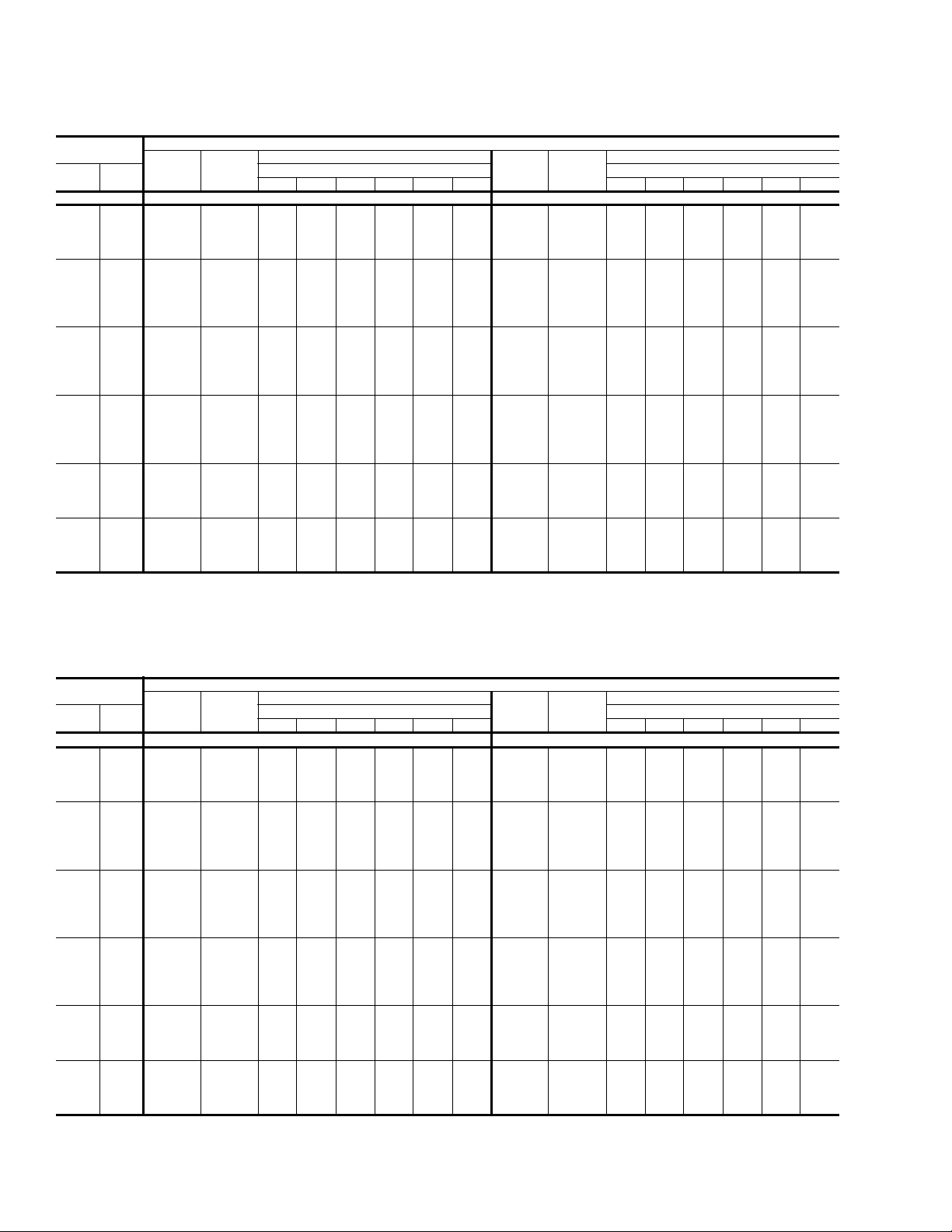
TABLE 5: BP060 COOLING CAPACITIES (5 TON)
Air on
Evaporator Coil
CFM
1250
1500
1750
2000
2250
2500
1250
1500
1750
2000
2250
2500
WB
(°F)
77 73.6 3.5 31.0 25.8 20.7 - - - 67.5 4.0 28.6 23.7 18.9 - - 72 66.3 3.4 38.7 33.6 28.4 23.3 - - 61.5 3.9 36.5 31.7 26.9 22.0 - 67 59.0 3.3 46.5 41.4 36.2 31.1 25.9 - 55.5 3.8 44.5 39.7 34.8 30.0 25.2 62 53.8 3.2 53.8 50.9 44.8 39.6 34.5 29.3 50.4 3.7 50.4 48.9 42.7 37.8 33.0 28.2
77 76.2 3.5 33.5 27.8 22.1 - - - 70.2 4.0 31.3 25.8 20.3 - - 72 68.6 3.4 41.8 36.1 30.5 24.8 - - 63.9 3.9 39.9 34.4 28.9 23.4 - 67 61.0 3.3 50.2 44.5 38.8 33.1 27.4 - 57.7 3.8 48.4 42.9 37.4 31.9 26.4 62 55.7 3.2 55.7 53.7 47.9 42.3 36.6 30.9 52.3 3.7 52.3 51.4 45.9 40.4 34.9 29.4
57 50.2 3.2 50.2 50.2 47.0 41.3 35.7 30.0 48.6 3.7 48.6 48.6 45.7 40.2 34.7 29.2
77 78.7 3.5 36.0 29.8 23.6 - - - 72.8 4.0 34.1 27.9 21.7 - - 72 70.9 3.4 44.9 38.7 32.5 26.3 - - 66.3 3.9 43.2 37.1 30.9 24.7 - 67 63.1 3.3 53.8 47.6 41.3 35.1 28.9 - 59.8 3.8 52.4 46.2 40.0 33.9 27.7 62 57.5 3.2 57.5 56.6 51.1 44.9 38.7 32.5 54.3 3.7 54.3 53.8 49.1 42.9 36.7 30.6
57 51.9 3.2 51.9 51.9 50.1 43.9 37.7 31.5 50.4 3.7 50.4 50.4 48.9 42.7 36.5 30.4
77 81.3 3.5 38.5 31.8 25.1 - - - 75.4 4.0 36.8 30.0 23.2 - - 72 73.2 3.4 48.0 41.2 34.5 27.7 - - 68.7 3.9 46.6 39.7 32.9 26.1 - 67 65.1 3.3 57.4 50.6 43.9 37.2 30.4 - 62.0 3.8 56.3 49.5 42.7 35.8 29.0 62 59.4 3.2 59.4 59.4 54.3 47.5 40.8 34.1 56.2 3.7 56.2 56.2 52.2 45.4 38.6 31.8
57 53.5 3.2 53.5 53.5 53.2 46.5 39.7 33.0 52.2 3.7 52.2 52.2 52.1 45.2 38.4 31.6
72 75.1 3.4 52.0 44.7 37.4 30.0 - - 70.0 3.9 50.2 42.8 35.4 28.0 - 67 66.8 3.3 63.0 54.9 47.6 40.2 32.9 - 63.2 3.8 60.3 53.3 45.9 38.5 31.1 62 61.0 3.2 61.0 61.0 58.4 51.1 43.7 36.4 57.3 3.7 57.3 57.3 55.3 47.9 40.5 33.2
57 55.0 3.2 55.0 55.0 54.8 47.5 40.1 32.8 53.2 3.7 53.2 53.2 53.1 45.7 38.4 31.0
72 77.0 3.5 56.1 48.2 40.2 32.3 - - 71.3 4.0 53.8 45.9 37.9 30.0 - 67 68.5 3.3 68.5 59.2 51.3 43.3 35.4 - 64.4 3.9 64.4 57.1 49.2 41.2 33.3 62 62.5 3.3 62.5 62.5 62.5 54.6 46.6 38.7 58.4 3.8 58.4 58.4 58.4 50.4 42.5 34.6
57 56.4 3.3 56.4 56.4 56.4 48.4 40.5 32.6 54.2 3.8 54.2 54.2 54.2 46.3 38.3 30.4
77 61.5 4.5 26.2 21.7 17.2 - - - 60.1 5.1 24.0 19.8 15.0 - - 72 56.8 4.4 34.3 29.8 25.3 20.8 - - 54.9 5.0 33.0 28.2 23.4 18.6 - 67 52.1 4.3 42.4 37.9 33.4 28.9 24.4 - 49.7 4.9 42.0 36.6 31.8 27.0 22.2 62 46.9 4.3 46.9 46.9 40.6 36.0 31.5 27.0 44.9 4.8 44.9 44.9 38.2 33.4 28.6 23.8
77 64.2 4.5 29.2 23.8 18.5 - - - 62.2 5.0 27.5 21.9 16.3 - - 72 59.3 4.4 37.9 32.6 27.3 22.0 - - 56.9 4.9 36.6 31.0 25.4 19.8 - 67 54.3 4.3 46.7 41.4 36.1 30.8 25.5 - 51.5 4.9 45.7 40.1 34.5 28.9 23.3 62 49.0 4.2 49.0 49.0 43.8 38.5 33.2 27.8 46.5 4.8 46.5 46.5 41.5 35.9 30.3 24.7
57 47.0 4.2 47.0 47.0 44.4 39.1 33.7 28.4 45.6 4.8 45.6 45.6 42.1 36.5 30.9 25.3
77 66.8 4.5 32.1 26.0 19.9 - - - 64.4 5.0 31.0 24.0 17.6 - - 72 61.7 4.4 41.5 35.4 29.3 23.2 - - 58.8 4.9 40.2 33.8 27.5 21.1 - 67 56.6 4.3 51.0 44.9 38.7 32.6 26.5 - 53.3 4.8 49.5 43.7 37.3 30.9 24.5 62 51.0 4.2 51.0 51.0 47.0 40.9 34.8 28.7 48.1 4.8 48.1 48.1 44.8 38.4 32.0 25.6
57 48.9 4.2 48.9 48.9 47.6 41.5 35.4 29.3 47.2 4.8 47.2 47.2 45.4 39.0 32.6 26.2
77 69.5 4.5 35.1 28.2 21.3 - - - 66.6 5.0 34.5 26.1 18.9 - - 72 64.2 4.4 45.2 38.2 31.3 24.4 - - 60.8 4.9 43.9 36.7 29.5 22.3 - 67 58.9 4.2 55.2 48.3 41.4 34.5 27.6 - 55.0 4.8 53.2 47.2 40.0 32.8 25.6 62 53.1 4.2 53.1 53.1 50.2 43.3 36.4 29.5 49.8 4.7 49.8 49.8 48.1 40.9 33.7 26.5
57 50.9 4.2 50.9 50.9 50.9 44.0 37.1 30.1 48.8 4.7 48.8 48.8 48.8 41.6 34.4 27.2
72 64.9 4.4 48.3 40.9 33.5 26.0 - - 61.5 4.9 46.9 39.2 31.5 23.8 - 67 59.5 4.3 57.7 51.7 44.2 36.8 29.4 - 55.7 4.9 54.7 50.4 42.7 35.0 27.3 62 53.7 4.2 53.7 53.7 52.2 44.8 37.4 29.9 50.3 4.8 50.3 50.3 49.5 41.8 34.0 26.3
57 51.5 4.2 51.5 51.5 51.5 44.0 36.6 29.2 49.3 4.8 49.3 49.3 49.3 41.6 33.9 26.2
72 65.6 4.5 51.5 43.6 35.6 27.7 - - 62.2 5.0 49.9 41.7 33.5 25.2 - 67 60.2 4.4 60.2 55.0 47.1 39.1 31.2 - 56.3 4.9 56.3 53.7 45.4 37.2 29.0 62 54.3 4.3 54.3 54.3 54.3 46.3 38.4 30.4 50.9 4.9 50.9 50.9 50.9 42.6 34.4 26.2
57 52.0 4.3 52.0 52.0 52.0 44.1 36.1 28.2 49.9 4.8 49.9 49.9 49.9 41.6 33.4 25.2
Total
Capacity
(MBh)
Total
1
Input
2
(kW)
Sensible Capacity (MBh)
Return Dry Bulb (°F) Return Dry Bulb (°F)
90 85 80 75 70 65 90 85 80 75 70 65
75°F 85°F
95°F 105°F
Temperature of Air on Condenser Coil
Total
Capacity
(MBh)
Total
1
Input
2
(kW)
Sensible Capacity (MBh)
Unitary Products Group 11
Page 12
255027-YTG-B-0507
TABLE 5: BP060 COOLING CAPACITIES (5 TON) (CONT.)
Air on
Evaporator Coil
CFM
1250
1500
1750
2000
2250
2500
WB
(°F)
77 58.7 5.6 21.9 18.0 12.9 - - - 57.3 6.1 18.9 16.2 10.8 - - 72 53.0 5.5 31.7 26.6 21.5 16.4 - - 51.1 6.1 30.5 25.1 19.7 14.3 - 67 47.3 5.5 41.6 35.3 30.2 25.1 20.0 - 44.9 6.0 41.1 33.9 28.5 23.1 17.7 62 42.9 5.4 42.9 42.9 35.8 30.7 25.6 20.5 40.8 6.0 40.8 40.8 33.5 28.1 22.7 17.3
77 60.3 5.5 25.9 20.0 14.1 - - - 58.4 6.1 24.3 18.1 11.9 - - 72 54.5 5.5 35.3 29.5 23.6 17.7 - - 52.1 6.0 34.1 27.9 21.7 15.5 - 67 48.6 5.4 44.8 38.9 33.0 27.1 21.2 - 45.7 6.0 43.8 37.6 31.4 25.3 19.1 62 44.1 5.4 44.1 44.1 39.2 33.3 27.4 21.5 41.6 6.0 41.6 41.6 36.9 30.7 24.5 18.3
57 44.3 5.4 44.3 44.3 39.8 33.9 28.0 22.2 42.9 6.0 42.9 42.9 37.6 31.4 25.2 19.0
77 62.0 5.5 29.9 22.0 15.3 - - - 59.5 6.0 29.7 20.0 13.1 - - 72 55.9 5.4 39.0 32.3 25.6 18.9 - - 53.0 6.0 37.7 30.7 23.7 16.7 - 67 49.9 5.4 48.0 42.5 35.8 29.1 22.4 - 46.5 5.9 46.5 41.3 34.4 27.4 20.4 62 45.2 5.4 45.2 45.2 42.5 35.9 29.2 22.5 42.3 5.9 42.3 42.3 40.3 33.4 26.4 19.4
57 45.5 5.3 45.5 45.5 43.2 36.6 29.9 23.2 43.7 5.9 43.7 43.7 41.1 34.1 27.1 20.1
77 63.6 5.5 33.9 24.0 16.6 - - - 60.6 6.0 35.2 22.0 14.2 - - 72 57.4 5.4 42.6 35.1 27.6 20.1 - - 54.0 5.9 41.3 33.5 25.7 18.0 - 67 51.2 5.3 51.2 46.1 38.6 31.2 23.7 - 47.3 5.9 47.3 45.0 37.3 29.5 21.8 62 46.4 5.3 46.4 46.4 45.9 38.4 31.0 23.5 43.1 5.9 43.1 43.1 43.1 36.0 28.2 20.5
57 46.7 5.3 46.7 46.7 46.7 39.2 31.7 24.2 44.6 5.9 44.6 44.6 44.6 36.8 29.0 21.3
72 58.0 5.5 45.4 37.4 29.5 21.5 - - 54.6 6.0 44.0 35.7 27.4 19.2 - 67 51.8 5.4 51.8 49.2 41.2 33.2 25.3 - 47.9 6.0 47.9 47.9 39.7 31.5 23.2 62 47.0 5.4 47.0 47.0 46.7 38.7 30.7 22.7 43.6 6.0 43.6 43.6 43.6 35.7 27.4 19.1
57 47.2 5.4 47.2 47.2 47.2 39.2 31.2 23.2 45.1 6.0 45.1 45.1 45.1 36.8 28.5 20.3
72 58.7 5.5 48.3 39.8 31.3 22.8 - - 55.2 6.1 46.7 37.9 29.1 20.4 - 67 52.4 5.5 52.4 52.3 43.8 35.3 26.8 - 48.4 6.0 48.4 48.4 42.2 33.4 24.6 62 47.5 5.5 47.5 47.5 47.5 39.0 30.5 22.0 44.1 6.0 44.1 44.1 44.1 35.3 26.5 17.7
57 47.7 5.4 47.7 47.7 47.7 39.2 30.7 22.2 45.6 6.0 45.6 45.6 45.6 36.8 28.0 19.2
Total
Capacity
(MBh)
Total
1
Input
2
(kW)
Sensible Capacity (MBh)
Return Dry Bulb (°F) Return Dry Bulb (°F)
90 85 80 75 70 65 90 85 80 75 70 65
115°F 125°F
1. These capacities are gross ratings. For net capacity, deduct air blower motor, MBh = 3.415 x kW. Refer to the appropriate Blower
Performance Table for the kW of the supply air blower motor.
2. These ratings include the condenser fan motors (total 1 kW) and the compressor motors but not the supply air blower motor.
Temperature of Air on Condenser Coil
Total
Capacity
(MBh)
Total
1
Input
(kW)
Sensible Capacity (MBh)
2
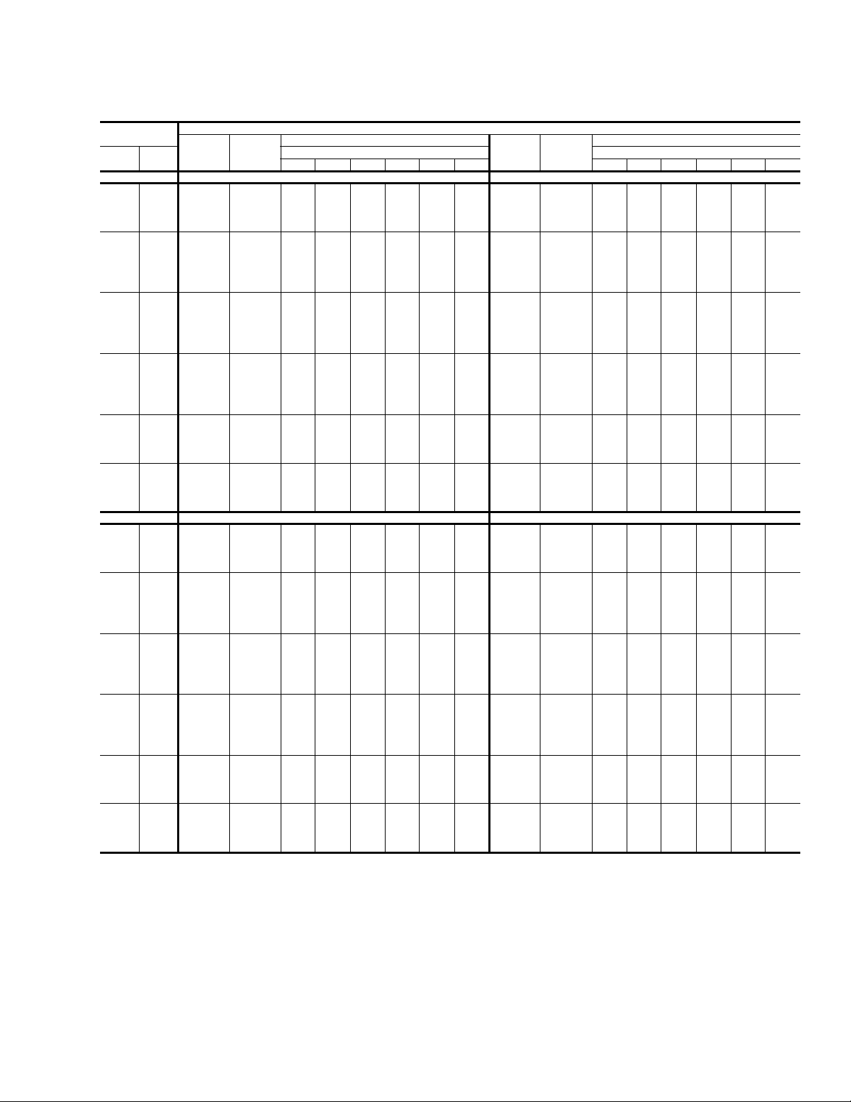
TABLE 6: BP072 COOLING CAPACITIES (6 TON)
Air on
Evaporator Coil
CFM
1500
1800
2100
2400
2700
3000
WB
(°F)
77 81.3 4.8 31.9 26.0 20.1 - - - 78.1 5.3 31.1 25.3 19.5 - - 72 77.2 4.7 43.3 37.4 31.5 25.6 - - 73.4 5.2 42.2 36.4 30.6 24.8 - 67 73.2 4.6 54.8 48.9 43.0 37.1 31.2 - 68.7 5.2 53.3 47.5 41.7 35.9 30.1 62 68.9 4.6 68.9 61.7 53.8 47.9 42.0 36.1 63.6 5.1 63.6 60.0 51.6 45.8 40.0 34.2
77 83.8 4.8 35.3 28.7 22.1 - - - 81.0 5.3 34.7 28.1 21.6 - - 72 79.6 4.7 48.0 41.4 34.8 28.2 - - 76.1 5.3 46.9 40.4 33.8 27.3 - 67 75.5 4.6 60.6 54.0 47.4 40.8 34.3 - 71.2 5.2 59.2 52.6 46.1 39.5 33.0 62 71.1 4.6 71.1 66.3 59.3 52.8 46.2 39.6 66.0 5.1 66.0 63.6 57.0 50.4 43.9 37.3
57 70.2 4.6 70.2 68.7 61.5 54.9 48.3 41.8 65.4 5.1 65.4 64.7 58.1 51.6 45.0 38.5
77 86.3 4.8 38.7 31.4 24.2 - - - 83.9 5.3 38.2 30.9 23.6 - - 72 82.1 4.7 52.6 45.3 38.0 30.7 - - 78.9 5.3 51.7 44.3 37.0 29.7 - 67 77.8 4.7 66.4 59.1 51.9 44.6 37.3 - 73.8 5.2 65.1 57.8 50.4 43.1 35.8 62 73.2 4.6 73.2 70.8 64.9 57.6 50.3 43.0 68.3 5.2 68.3 67.1 62.4 55.1 47.7 40.4
57 72.3 4.6 72.3 71.6 67.3 60.0 52.7 45.4 67.8 5.1 67.8 67.4 63.6 56.3 49.0 41.7
77 88.8 4.8 42.2 34.2 26.2 - - - 86.8 5.4 41.8 33.7 25.6 - - 72 84.5 4.7 57.2 49.2 41.2 33.3 - - 81.6 5.3 56.4 48.3 40.2 32.1 - 67 80.1 4.7 72.2 64.2 56.3 48.3 40.3 - 76.3 5.2 71.0 62.9 54.8 46.7 38.6 62 75.4 4.6 75.4 75.4 70.4 62.4 54.5 46.5 70.7 5.2 70.7 70.7 67.8 59.7 51.6 43.5
57 74.5 4.6 74.5 74.5 73.0 65.0 57.0 49.1 70.1 5.2 70.1 70.1 69.1 61.0 52.9 44.9
72 86.9 4.7 59.9 51.6 43.2 34.9 - - 83.3 5.3 59.1 50.6 42.1 33.6 - 67 82.4 4.7 76.8 67.3 59.0 50.6 42.3 - 77.9 5.2 74.4 65.9 57.4 48.9 40.3 62 77.6 4.6 77.6 77.6 75.1 66.7 58.4 50.0 72.1 5.2 72.1 72.1 70.7 62.2 53.7 45.2
57 76.6 4.6 76.6 76.6 75.9 67.5 59.2 50.8 71.6 5.2 71.6 71.6 71.1 62.6 54.0 45.5
72 89.4 4.7 62.7 53.9 45.2 36.5 - - 84.9 5.3 61.8 52.9 44.0 35.0 - 67 84.7 4.7 81.3 70.4 61.7 52.9 44.2 - 79.5 5.2 77.8 68.9 59.9 51.0 42.1 62 79.7 4.6 79.7 79.7 79.7 71.0 62.3 53.5 73.6 5.2 73.6 73.6 73.6 64.7 55.7 46.8
57 78.8 4.6 78.8 78.8 78.8 70.0 61.3 52.6 73.0 5.2 73.0 73.0 73.0 64.1 55.1 46.2
Total
Capacity
(MBh)
Total
1
Input
2
(kW)
Sensible Capacity (MBh)
Return Dry Bulb (°F) Return Dry Bulb (°F)
90 85 80 75 70 65 90 85 80 75 70 65
75°F 85°F
Temperature of Air on Condenser Coil
Total
Capacity
(MBh)
Total
1
Input
2
(kW)
Sensible Capacity (MBh)
12 Unitary Products Group
Page 13
255027-YTG-B-0507
TABLE 6: BP072 COOLING CAPACITIES (6 TON) (CONT.)
Air on
Evaporator Coil
CFM
1500
1800
2100
2400
2700
3000
1500
1800
2100
2400
2700
3000
WB
(°F)
77 75.0 5.8 30.3 24.7 19.0 - - - 69.9 6.5 27.3 22.6 17.2 - - 72 69.6 5.8 41.1 35.4 29.7 24.0 - - 64.1 6.4 38.1 32.6 27.2 21.7 - 67 64.2 5.7 51.8 46.1 40.4 34.7 29.1 - 58.4 6.3 48.8 42.6 37.1 31.7 26.2 62 58.3 5.6 58.3 58.3 49.4 43.7 38.0 32.4 53.6 6.3 53.6 53.6 44.7 39.2 33.7 28.3
77 78.3 5.8 34.1 27.5 21.0 - - - 73.6 6.6 32.1 25.7 19.4 - - 72 72.6 5.8 45.9 39.4 32.9 26.3 - - 67.5 6.5 43.3 37.0 30.6 24.2 - 67 67.0 5.7 57.8 51.3 44.7 38.2 31.7 - 61.4 6.4 54.6 48.2 41.8 35.4 29.1 62 60.9 5.7 60.9 60.9 54.7 48.1 41.6 35.1 56.3 6.3 56.3 56.3 50.3 43.9 37.5 31.1
57 60.7 5.7 60.7 60.7 54.7 48.2 41.7 35.2 55.9 6.3 55.9 55.9 49.9 43.5 37.1 30.8
77 81.6 5.9 37.8 30.4 23.0 - - - 77.2 6.6 36.9 28.8 21.5 - - 72 75.7 5.8 50.8 43.4 36.0 28.7 - - 70.8 6.5 48.6 41.3 34.0 26.7 - 67 69.8 5.8 63.8 56.4 49.0 41.7 34.3 - 64.4 6.4 60.3 53.8 46.5 39.2 31.9 62 63.4 5.7 63.4 63.4 59.9 52.5 45.2 37.8 59.1 6.4 59.1 59.1 55.9 48.6 41.2 33.9
57 63.2 5.7 63.2 63.2 60.0 52.6 45.3 37.9 58.6 6.3 58.6 58.6 55.4 48.1 40.8 33.5
77 84.8 5.9 41.5 33.3 25.0 - - - 80.9 6.6 41.7 31.9 23.7 - - 72 78.7 5.9 55.6 47.4 39.2 31.0 - - 74.2 6.5 53.9 45.7 37.4 29.2 - 67 72.6 5.8 69.8 61.6 53.3 45.1 36.9 - 67.4 6.5 66.1 59.4 51.2 42.9 34.7 62 66.0 5.7 66.0 66.0 65.2 57.0 48.7 40.5 61.9 6.4 61.9 61.9 61.5 53.2 45.0 36.8
57 65.7 5.7 65.7 65.7 65.3 57.1 48.8 40.6 61.4 6.4 61.4 61.4 61.0 52.8 44.5 36.3
72 79.6 5.9 58.3 49.6 41.0 32.3 - - 74.3 6.6 56.1 47.4 38.8 30.2 - 67 73.4 5.8 72.0 64.4 55.8 47.1 38.4 - 67.6 6.5 66.9 61.7 53.0 44.4 35.8 62 66.7 5.7 66.7 66.7 66.3 57.7 49.0 40.3 62.1 6.4 62.1 62.1 61.9 53.2 44.6 35.9
57 66.5 5.7 66.5 66.5 66.3 57.6 48.9 40.2 61.5 6.4 61.5 61.5 61.3 52.7 44.1 35.4
72 80.5 5.9 61.0 51.9 42.8 33.6 - - 74.5 6.6 58.2 49.2 40.2 31.1 - 67 74.2 5.8 74.2 67.3 58.2 49.1 40.0 - 67.8 6.5 67.8 63.9 54.9 45.9 36.8 62 67.5 5.8 67.5 67.5 67.5 58.3 49.2 40.1 62.2 6.4 62.2 62.2 62.2 53.2 44.2 35.1
57 67.2 5.8 67.2 67.2 67.2 58.1 49.0 39.9 61.7 6.4 61.7 61.7 61.7 52.7 43.6 34.6
77 64.9 7.2 24.3 20.6 15.4 - - - 59.8 7.9 20.5 18.6 13.6 - - 72 58.7 7.1 35.1 29.9 24.6 19.4 - - 53.3 7.8 32.1 27.1 22.1 17.1 - 67 52.5 7.0 45.9 39.1 33.8 28.6 23.4 - 46.7 7.6 42.9 35.6 30.6 25.6 20.6 62 48.8 6.9 48.8 48.8 39.9 34.7 29.5 24.2 44.0 7.6 44.0 44.0 35.2 30.2 25.2 20.2
77 68.9 7.3 30.2 23.9 17.7 - - - 64.2 8.0 28.2 22.2 16.1 - - 72 62.3 7.1 40.8 34.5 28.3 22.1 - - 57.2 7.8 38.2 32.1 26.0 19.9 - 67 55.8 7.0 51.4 45.1 38.9 32.7 26.4 - 50.2 7.7 48.1 42.1 36.0 29.9 23.8 62 51.8 7.0 51.8 51.8 45.9 39.6 33.4 27.2 47.3 7.6 47.3 47.3 41.5 35.4 29.3 23.2
57 51.1 6.9 51.1 51.1 45.0 38.8 32.6 26.3 46.2 7.6 46.2 46.2 40.2 34.1 28.0 21.9
77 72.9 7.3 36.1 27.3 20.0 - - - 68.6 8.0 35.9 25.7 18.5 - - 72 66.0 7.2 46.5 39.2 32.0 24.7 - - 61.1 7.9 44.3 37.1 29.9 22.8 - 67 59.1 7.1 56.8 51.2 43.9 36.7 29.4 - 53.7 7.7 53.4 48.6 41.4 34.2 27.0 62 54.8 7.0 54.8 54.8 51.8 44.6 37.3 30.1 50.6 7.7 50.6 50.6 47.8 40.6 33.4 26.2
57 54.0 7.0 54.0 54.0 50.9 43.6 36.4 29.2 49.5 7.6 49.5 49.5 46.3 39.1 32.0 24.8
77 76.9 7.4 42.0 30.6 22.3 - - - 73.0 8.1 43.6 29.2 20.9 - - 72 69.6 7.2 52.2 43.9 35.6 27.4 - - 65.1 7.9 50.4 42.1 33.9 25.6 - 67 62.3 7.1 62.3 57.2 49.0 40.7 32.5 - 57.2 7.8 57.2 55.1 46.8 38.5 30.3 62 57.9 7.1 57.9 57.9 57.8 49.5 41.2 33.0 53.8 7.7 53.8 53.8 53.8 45.8 37.5 29.2
57 57.0 7.0 57.0 57.0 56.7 48.5 40.2 32.0 52.7 7.7 52.7 52.7 52.5 44.2 35.9 27.6
72 69.1 7.3 53.8 45.2 36.6 28.0 - - 63.8 7.9 51.5 43.0 34.4 25.8 - 67 61.8 7.1 61.8 58.9 50.3 41.7 33.1 - 56.1 7.8 56.1 56.1 47.6 39.0 30.4 62 57.4 7.1 57.4 57.4 57.4 48.8 40.2 31.6 52.8 7.8 52.8 52.8 52.8 44.3 35.8 27.2
57 56.6 7.1 56.6 56.6 56.4 47.8 39.2 30.6 51.6 7.7 51.6 51.6 51.5 43.0 34.4 25.8
72 68.6 7.3 55.5 46.5 37.6 28.6 - - 62.6 8.0 52.7 43.8 35.0 26.1 - 67 61.4 7.1 61.4 60.6 51.6 42.7 33.7 - 54.9 7.8 54.9 54.9 48.3 39.5 30.6 62 57.0 7.1 57.0 57.0 57.0 48.0 39.1 30.1 51.8 7.8 51.8 51.8 51.8 42.9 34.0 25.2
57 56.1 7.1 56.1 56.1 56.1 47.2 38.3 29.3 50.6 7.7 50.6 50.6 50.6 41.7 32.9 24.0
Total
Capacity
(MBh)
Total
1
Input
2
(kW)
Sensible Capacity (MBh)
Return Dry Bulb (°F) Return Dry Bulb (°F)
90 85 80 75 70 65 90 85 80 75 70 65
95°F 105°F
115°F 125°F
1. These capacities are gross ratings. For net capacity, deduct air blower motor, MBh = 3.415 x kW. Refer to the appropriate Blower
Performance Table for the kW of the supply air blower motor.
2. These ratings include the condenser fan motors (total 1 kW) and the compressor motors but not the supply air blower motor.
Temperature of Air on Condenser Coil
Total
Capacity
(MBh)
Total
1
Input
(kW)
Sensible Capacity (MBh)
2
Unitary Products Group 13
Page 14
TABLE 7: BP036-072 HEATING CAPACITIES
Size
(Tons)
036
(3)
048
(4)
060
(5)
Air Over Evaporator
CFM DB (°F) -10 0 10 20 30 40 50 60
1200
1500
1200
1600
2000
1500
2000
2500
900
Coil
Capacity
55
70
80
55
70
80
55
70
80
55
70
80
55
70
80
55
70
80
55
70
80
55
70
80
55
70
80
1
& kW
MBH 2.4 7.6 12.8 18.0 23.1 28.3 33.5 38.7
KW 1.6 1.8 1.9 2.1 2.2 2.4 2.5 2.7
MBH - 4.6 9.8 15.0 20.1 25.3 30.5 35.7
KW - 2.0 2.1 2.3 2.4 2.6 2.8 2.9
MBH - 2.8 8.0 13.1 18.3 23.5 28.7 33.8
KW - 2.1 2.3 2.5 2.6 2.8 2.9 3.1
MBH 4.3 9.5 14.7 19.8 25.0 30.2 35.4 40.5
KW 1.5 1.7 1.8 2.0 2.1 2.3 2.4 2.6
MBH 1.3 6.5 11.7 16.8 22.0 27.2 32.4 37.5
KW 1.7 1.9 2.0 2.2 2.3 2.5 2.6 2.8
MBH - 4.6 9.8 15.0 20.2 25.3 30.5 35.7
KW - 2.0 2.2 2.3 2.5 2.6 2.8 2.9
MBH 5.4 10.6 15.8 21.0 26.1 31.3 36.5 41.7
KW 1.4 1.6 1.7 1.9 2.0 2.2 2.4 2.5
MBH 2.4 7.6 12.8 18.0 23.1 28.3 33.5 38.7
KW 1.6 1.8 1.9 2.1 2.3 2.4 2.6 2.7
MBH 0.6 5.8 11.0 16.1 21.3 26.5 31.6 36.8
KW 1.8 2.0 2.1 2.3 2.4 2.6 2.7 2.9
MBH 2.3 9.6 17.0 24.3 31.6 38.9 46.2 53.5
KW 2.0 2.2 2.4 2.6 2.7 2.9 3.1 3.3
MBH - 5.8 13.1 20.4 27.7 35.0 42.3 49.7
KW - 2.5 2.7 2.9 3.1 3.3 3.5 3.6
MBH - 3.1 10.4 17.7 25.0 32.4 39.7 47.0
KW - 2.6 2.8 3.0 3.2 3.4 3.6 3.8
MBH 5.0 12.3 19.7 27.0 34.3 41.6 48.9 56.2
KW 1.8 2.0 2.2 2.4 2.6 2.8 3.0 3.2
MBH 1.1 8.5 15.8 23.1 30.4 37.7 45.0 52.3
KW 2.2 2.4 2.5 2.7 2.9 3.1 3.3 3.5
MBH - 5.8 13.1 20.4 27.7 35.1 42.4 49.7
KW - 2.5 2.7 2.9 3.1 3.3 3.5 3.7
MBH 6.4 13.7 21.0 28.3 35.6 43.0 50.3 57.6
KW 1.7 1.9 2.1 2.3 2.5 2.7 2.9 3.1
MBH 2.5 9.8 17.1 24.5 31.8 39.1 46.4 53.7
KW 2.0 2.2 2.4 2.6 2.8 3.0 3.2 3.4
MBH - 7.2 14.5 21.8 29.1 36.4 43.7 51.1
KW - 2.4 2.6 2.7 2.9 3.1 3.3 3.5
MBH 7.8 15.6 23.4 31.2 38.9 46.7 54.5 62.3
KW 2.9 3.0 3.2 3.3 3.4 3.6 3.7 3.9
MBH 6.2 14.0 21.8 29.6 37.3 45.1 52.9 60.7
KW 3.5 3.7 3.8 4.0 4.1 4.3 4.4 4.5
MBH 4.9 12.7 20.5 28.3 36.0 43.8 51.6 59.4
KW 4.0 4.2 4.3 4.5 4.6 4.8 4.9 5.0
MBH 8.0 15.8 23.6 31.4 39.1 46.9 54.7 62.5
KW 2.5 2.7 2.8 2.9 3.1 3.2 3.4 3.5
MBH 6.5 14.2 22.0 29.8 37.6 45.4 53.1 60.9
KW 3.2 3.3 3.5 3.6 3.8 3.9 4.0 4.2
MBH 5.2 12.9 20.7 28.5 36.3 44.1 51.8 59.6
KW 3.7 3.8 4.0 4.1 4.3 4.4 4.5 4.7
MBH 8.9 16.7 24.5 32.2 40.0 47.8 55.6 63.3
KW 2.3 2.5 2.6 2.7 2.9 3.0 3.2 3.3
MBH 7.3 15.1 22.9 30.6 38.4 46.2 54.0 61.8
KW 3.0 3.1 3.3 3.4 3.6 3.7 3.8 4.0
MBH 6.0 13.8 21.5 29.3 37.1 44.9 52.7 60.4
KW 3.5 3.6 3.8 3.9 4.1 4.2 4.3 4.5
255027-YTG-B-0507
Outdoor Temperature (°F @ 72% RH)
14 Unitary Products Group
Page 15

255027-YTG-B-0507
TABLE 7: BP036-072 HEATING CAPACITIES (CONT.)
Size
(Tons)
072
(6)
Air Over Evaporator
Coil
Capacity
1
& kW
CFM DB (°F) -10 0 10 20 30 40 50 60
MBH 11.3 20.8 30.3 39.8 49.2 58.7 68.2 77.7
KW 3.4 3.7 4.0 4.2 4.5 4.8 5.0 5.3
MBH 10.1 19.6 29.0 38.5 48.0 57.5 66.9 76.4
KW 4.1 4.4 4.6 4.9 5.2 5.4 5.7 6.0
MBH 7.9 17.3 26.8 36.3 45.8 55.2 64.7 74.2
KW 4.6 4.8 5.1 5.4 5.6 5.9 6.2 6.4
MBH 13.2 22.6 32.1 41.6 51.1 60.5 70.0 79.5
KW 3.0 3.3 3.6 3.8 4.1 4.4 4.6 4.9
MBH 11.9 21.4 30.9 40.4 49.8 59.3 68.8 78.3
KW 3.7 4.0 4.3 4.5 4.8 5.1 5.3 5.6
MBH 9.6 19.1 28.6 38.0 47.5 57.0 66.5 75.9
KW 4.2 4.4 4.7 5.0 5.2 5.5 5.8 6.0
MBH 13.8 23.2 32.7 42.2 51.7 61.1 70.6 80.1
KW 2.9 3.1 3.4 3.7 3.9 4.2 4.5 4.7
MBH 12.5 22.0 31.5 40.9 50.4 59.9 69.4 78.8
KW 3.6 3.8 4.1 4.4 4.6 4.9 5.2 5.4
MBH 10.3 19.8 29.2 38.7 48.2 57.7 67.1 76.6
KW 4.0 4.3 4.5 4.8 5.1 5.3 5.6 5.9
1800
2400
3000
55
70
80
55
70
80
55
70
80
1. These capacities do not include the supply air blower motor heat. For net capacity, add motor heat, MBh = 3.415 x kW.
Outdoor Temperature (°F @ 72% RH)
TABLE 8: SUPPLY AIR BLOWER PERFORMANCE (BP036 BELT DRIVE) - SIDE DUCT APPLICATION
AIR
FLOW
CFM
0.2 0.3 0.4 0.5 0.6
RPM WATTS BHP RPM WATTS BHP RPM WATTS BHP RPM WATTS BHP RPM WATTS BHP
AVAILABLE EXTERNAL STATIC PRESSURE - IWG
800 - - - - - - 696 357 0.38 743 389 0.42 786 422 0.45
900 - - - 656 353 0.38 706 385 0.41 753 417 0.45 797 450 0.48
1000 - - - 671 376 0.40 722 408 0.44 768 440 0.47 812 473 0.51
1100 634 364 0.39 690 398 0.43 741 431 0.46 787 463 0.50 831 496 0.53
1200 656 389 0.42 712 423 0.45 763 455 0.49 809 488 0.52 853 520 0.56
1300 681 418 0.45 737 452 0.49 787 485 0.52 834 517 0.55 877 550 0.59
1400 707 454 0.49 763 488 0.52 813 520 0.56 860 552 0.59
1500 735 496 0.53 791 530 0.57 841 562 0.60 887 594 0.64
1600 763 545 0.58 819 579 0.62 870 612 0.66
1700 793 602 0.65 849 636 0.68
1800 824 667 0.72 880 701 0.75
1900 855 739 0.79
2000 887 819 0.88
AIR
FLOW
CFM
RPM WATTS BHP RPM WATTS BHP RPM WATTS BHP RPM WATTS BHP RPM WATTS BHP
0.7 0.8 0.9 1.0 1.1
800 829 457 0.49
900 839 485 0.52
1000 854 508 0.55
1100 874 531 0.57
1200
1300
1400
1500
1600
1700
1800
1900
896 555 0.60 938 594 0.64 983 636 0.68 1031 685 0.73 1084 740 0.79
920 585 0.63 963 623 0.67 1007 666 0.71 1055 714 0.77 1108 770 0.83
946 620 0.67 989 659 0.71 1034 701 0.75 1082 750 0.80 - - -
974 662 0.71 1017 701 0.75 1061 743 0.80 1109 792 0.85 - - 1003 712 0.76 1045 750 0.80 1090 793 0.85 - - - - - 1032 769 0.82 1075 807 0.87 - - - - - - - - 1063 833 0.89 1106 872 0.94 - - - - - - - - 1094 906 0.97 - - - - - - - - - - - -
911 773 0.83 962 806 0.86 1008 838 0.90 1052 871 0.93
943 853 0.92 994 886 0.95 1040 918 0.98 1084 951 1.02
AVAILABLE EXTERNAL STATIC PRESSURE - IWG
872 495 0.53 916 538 0.58 964 586 0.63 1017 642 0.69
882 524 0.56 927 566 0.61 975 615 0.66 1027 670 0.72
897 547 0.59 942 589 0.63 990 638 0.68 1043 693 0.74
916 569 0.61 961 612 0.66 1009 660 0.71 1062 715 0.77
900 669 0.72 946 701 0.75 990 734 0.79
930 733 0.79 977 765 0.82 1021 798 0.86
916 644 0.69 960 677 0.73
2000 - - - - - - - - - - - - - - -
1. Blower performance inc ludes 1” filters. See STATIC RESISTANCE table for additional applications.
Factory Installed AK74 blower sheave and A39 belt.
AK61 blower sheave and A36 belt - Field installation required.
1
903 585 0.63
931 627 0.67
1
Unitary Products Group 15
Page 16

255027-YTG-B-0507
TABLE 9: SUPPLY AIR BLOWER PERFORMANCE (BP036 BELT DRIVE) - BOTTOM DUCT APPLICATION
AIR
FLOW
CFM
0.2 0.3 0.4 0.5 0.6
RPM WATTS BHP RPM WATTS BHP RPM WATTS BHP RPM WATTS BHP RPM WATTS BHP
AVAILABLE EXTERNAL STATIC PRESSURE - IWG
800 - - - - - - - - - 749 384 0.41 791 422 0.45
900 - - - - - - 720 364 0.39 764 404 0.43 806 443 0.47
1000 - - - 690 346 0.37 739 388 0.42 783 429 0.46 824 467 0.50
1100 657 334 0.36 711 376 0.40 760 417 0.45 804 458 0.49 845 497 0.53
1200 681 369 0.40 735 410 0.44 784 452 0.49 828 493 0.53 869 532 0.57
1300 707 409 0.44 761 451 0.48 809 493 0.53 854 534 0.57
1400 735 456 0.49 789 498 0.53 837 540 0.58 882 581 0.62
1500 765 509 0.55 819 550 0.59 867 592 0.64
1600 796 567 0.61 850 609 0.65
1700 829 631 0.68 883 673 0.72
1800 863 701 0.75
1900
2000
899 776 0.83 953 818 0.88 1001 860 0.92 1045 901 0.97 1087 939 1.01
936 857 0.92 990 899 0.96 1038 941 1.01 1082 981 1.05 - - -
918 743 0.80 966 785 0.84 1010 826 0.89 1051 864 0.93
899 651 0.70 943 692 0.74 984 730 0.78
932 715 0.77 976 756 0.81 1017 794 0.85
911 633 0.68 953 672 0.72
1
895 572 0.61
923 619 0.66
AIR
FLOW
CFM
RPM WATTS BHP RPM WATTS BHP RPM WATTS BHP RPM WATTS BHP RPM WATTS BHP
0.7 0.8 0.9 1.0 1.1
800 831 456 0.49
900 846 477 0.51
1000
1100
1200
1300
1400
1500
1600
1700
1800
864 502 0.54 905 531 0.57 947 555 0.60 994 571 0.61 1046 578 0.62
885 531 0.57 926 561 0.60 969 584 0.63 1015 600 0.64 1067 607 0.65
909 566 0.61 950 596 0.64 992 619 0.66 1039 635 0.68 1091 642 0.69
935 607 0.65 976 636 0.68 1018 660 0.71 1065 676 0.72 - - 963 654 0.70 1004 683 0.73 1046 707 0.76 1093 722 0.77 - - -
993 706 0.76 1033 736 0.79 1076 759 0.81 - - - - - 1024 765 0.82 1065 794 0.85 1108 818 0.88 - - - - - 1057 829 0.89 1098 859 0.92 - - - - - - - - 1091 899 0.96 - - - - - - - - - - - -
AVAILABLE EXTERNAL STATIC PRESSURE - IWG
871 486 0.52 914 509 0.55 961 525 0.56 1012 532 0.57
886 507 0.54 929 530 0.57 976 546 0.59 1027 553 0.59
1
1900 - - - - - - - - - - - - - - 2000 - - - - - - - - - - - - - - -
1. Blower performance inc ludes 1” filters. See STATIC RESISTANCE table for additional applications.
Factory Installed AK74 blower sheave and A39 belt.
AK61 blower sheave and A36 belt - Field installation required.
16 Unitary Products Group
Page 17

255027-YTG-B-0507
TABLE 10: SUPPLY AIR BLOWER PERFORMANCE (BP048 BELT DRIVE) - SIDE DUCT APPLICATION
AIR
FLOW
CFM
RPM WATTS BHP RPM WATTS BHP RPM WATTS BHP RPM WATTS BHP RPM WATTS BHP RPM WATTS BHP
0.2 0.3 0.4 0.5 0.6 0.7
AVAILABLE EXTERNAL STATIC PRESSURE - IWG
1000 - - - - - - - - - 789 527 0.57 831 567 0.61 874 602 0.65
1100 - - - - - - - - - 811 559 0.60 854 599 0.64 896 634 0.68
1200 - - - - - - 791 548 0.59 833 592 0.63 876 632 0.68 918 667 0.72
1300 - - - 772 539 0.58 813 584 0.63 855 628 0.67 898 668 0.72 940 703 0.75
1400 - - - 795 579 0.62 836 624 0.67 878 668 0.72 920 708 0.76 963 744 0.80
1500 779 578 0.62 819 624 0.67 860 669 0.72 902 713 0.77 944 753 0.81 987 789 0.85
1600 804 629 0.67 844 675 0.72 885 720 0.77 927 764 0.82 970 804 0.86 1013 839 0.90
1700 831 685 0.74 871 731 0.78 913 777 0.83 955 820 0.88 997 861 0.92 1040 896 0.96
1800 860 748 0.80 901 794 0.85 942 839 0.90 984 883 0.95 1026 923 0.99 1069 958 1.03
1900 891 817 0.88 931 862 0.92 973 908 0.97 1015 951 1.02 1057 992 1.06
2000 924 891 0.96 964 937 1.01 1005 982 1.05 1047 1026 1.10 1090 1066 1.14
2100 959 972 1.04 999 1018 1.09 1040 1063 1.14 1082 1107 1.19
2200 996 1059 1.14 1036 1104 1.18 1077 1150 1.23
1034 1151 1.24 1075 1197 1.28 1116 1243 1.33 1158 1286 1.38 - - - - - -
2300
1075 1250 1.34 1115 1296 1.39 1156 1341 1.44 - - - - - - - - -
2400
1118 1354 1.45 1158 1400 1.50 - - - - - - - - - - - -
2500
1119 1194 1.28 1162 1234 1.32 - - -
1
1100 1027 1.10
1133 1102 1.18
1125 1147 1.23 1167 1182 1.27
AIR
FLOW
CFM
RPM WATTS BHP RPM WATTS BHP RPM WATTS BHP RPM WATTS BHP RPM WATTS BHP RPM WATTS BHP
0.8 0.9 1.0 1.1 1.2 1.3
AVAILABLE EXTERNAL STATIC PRESSURE - IWG
1000 917 631 0.68 959 651 0.70 1001 660 0.71 1041 658 0.71
1100 939 663 0.71 981 683 0.73 1023 692 0.74 1064 690 0.74
1200 961 696 0.75 1003 716 0.77 1045 725 0.78
1300 983 732 0.79 1025 752 0.81 1067 761 0.82
1400 1006 772 0.83 1048 792 0.85
1500 1030 817 0.88 1072 837 0.90
1600 1055 868 0.93 1098 888 0.95
1700 1083 924 0.99
1112 987 1.06 1154 1007 1.08 - - - - - - - - - - - -
1800
1142 1055 1.13 1185 1075 1.15 - - - - - - - - - - - -
1900
1175 1130 1.21---------------
2000
1125 944 1.01 1166 954 1.02 - - - - - - - - -
1090 801 0.86 1130 799 0.86 1170 783 0.84 - - 1114 847 0.91 1154 844 0.91 1194 829 0.89 - - 1139 897 0.96 1180 895 0.96 - - - - - -
1086 723 0.78 1125 707 0.76 1163 676 0.73
1108 759 0.81 1147 743 0.80 1185 712 0.76
1
1081 642 0.69 1119 611 0.66
1103 674 0.72 1141 643 0.69
2100 - - - - - - - - - - - - - - - - - 2200 - - - - - - - - - - - - - - - - - 2300 - - - - - - - - - - - - - - - - - 2400 - - - - - - - - - - - - - - - - - 2500 - - - - - - - - - - - - - - - - - -
1. Blower performance includes 1” filters. See STATIC RESISTANCE table for additional applications.
Factory Installed AK61 blo w er she ave and A36 belt.
AK56 blower sheave and A36 belt - Field installation required.
Unitary Products Group 17
Page 18

255027-YTG-B-0507
TABLE 11: SUPPLY AIR BLOWER PERFORMANCE (BP048 BELT DRIVE) - BOTTOM DUCT APPLICATION
AIR
FLOW
CFM
RPM WATTS BHP RPM WATTS BHP RPM WATTS BHP RPM WATTS BHP RPM WATTS BHP RPM WATTS BHP
0.2 0.3 0.4 0.5 0.6 0.7
AVAILABLE EXTERNAL STATIC PRESSURE - IWG
1000 - - - - - - - - - - - - 833 564 0.61 879 605 0.65
1100 - - - - - - - - - 809 549 0.59 854 592 0.63 900 633 0.68
1200 - - - - - - 786 538 0.58 830 581 0.62 875 623 0.67 920 664 0.71
1300 - - - 766 535 0.57 808 574 0.62 851 617 0.66 896 659 0.71 942 700 0.75
1400 749 541 0.58 789 576 0.62 830 616 0.66 874 658 0.71 918 701 0.75 964 742 0.80
1500 774 587 0.63 813 622 0.67 855 662 0.71 898 705 0.76 943 747 0.80 989 788 0.85
1600 801 639 0.69 840 674 0.72 881 714 0.77 925 757 0.81 970 799 0.86 1015 840 0.90
1700 830 697 0.75 869 732 0.79 911 772 0.83 954 814 0.87 999 857 0.92 1045 898 0.96
1800 862 760 0.81 901 795 0.85 943 835 0.90 986 877 0.94 1031 920 0.99
1900 897 828 0.89 936 863 0.93 977 903 0.97 1021 945 1.01
2000 934 901 0.97 973 936 1.00 1015 976 1.05 1058 1018 1.09
2100 974 979 1.05 1013 1014 1.09 1055 1054 1.13
2200 1017 1063 1.14 1056 1098 1.18
2300 1063 1151 1.23
1111 1243 1.33 1151 1278 1.37 1192 1318 1.41 - - - - - - - - -
2400
1163 1340 1.44 1202 1376 1.48 - - - - - - - - - - - -
2500
1102 1186 1.27 1144 1226 1.31 1187 1268 1.36 - - - - - -
1098 1138 1.22 1141 1180 1.27 1186 1223 1.31 - - -
1098 1097 1.18 1143 1139 1.22 1189 1180 1.27
1
1077 960 1.03
1066 988 1.06 1111 1029 1.10
1103 1061 1.14 1149 1102 1.18
AIR
FLOW
CFM
RPM WATTS BHP RPM WATTS BHP RPM WATTS BHP RPM WATTS BHP RPM WATTS BHP RPM WATTS BHP
0.8 0.9 1.0 1.1 1.2 1.3
AVAILABLE EXTERNAL STATIC PRESSURE - IWG
1000 925 642 0.69 971 673 0.72 1017 696 0.75 1061 708 0.76
1100 946 670 0.72 992 701 0.75 1037 723 0.78 1082 736 0.79
1200 967 701 0.75 1013 732 0.79 1058 755 0.81
1300 988 737 0.79 1034 768 0.82 1079 791 0.85
1400 1010 779 0.84 1056 809 0.87
1500 1035 825 0.89 1081 856 0.92
1600 1062 877 0.94
1091 935 1.00 1137 966 1.04 1182 988 1.06 - - - - - - - - -
1700
1123 997 1.07 1169 1028 1.10 - - - - - - - - - - - -
1800
1157 1066 1.14---------------
1900
1195 1139 1.22---------------
2000
1108 908 0.97 1153 931 1.00 1197 943 1.01 - - - - - -
1102 832 0.89 1146 844 0.91 1188 844 0.91 - - 1126 879 0.94 1170 891 0.96 - - - - - -
1102 767 0.82 1145 767 0.82 1185 752 0.81
1123 803 0.86 1166 803 0.86 - - -
1
1103 708 0.76 1144 693 0.74
1124 735 0.79 1165 721 0.77
2100 - - - - - - - - - - - - - - - - - 2200 - - - - - - - - - - - - - - - - - 2300 - - - - - - - - - - - - - - - - - 2400 - - - - - - - - - - - - - - - - - 2500 - - - - - - - - - - - - - - - - - -
1. Blower performance in cludes 1” filters. See STATIC RESISTANCE table for additional applications.
Factory Installed AK61 blo w er she ave and A36 belt.
AK56 blower sheave and A36 belt - Field installation required.
18 Unitary Products Group
Page 19

255027-YTG-B-0507
TABLE 12: SUPPLY AIR BLOWER PERFORMANCE (BP060 BELT DRIVE) - SIDE DUCT APPLICATION
AIR
FLOW
CFM
RPM WATTS BHP RPM WATTS BHP RPM WATTS BHP RPM WATTS BHP RPM WATTS BHP RPM WATTS BHP
0.2 0.3 0.4 0.5 0.6 0.7
AVAILABLE EXTERNAL STATIC PRESSURE - IWG
1200 - - - - - - - - - - - - 876 632 0.68 918 667 0.72
1300 - - - - - - - - - 855 628 0.67 898 668 0.72 940 703 0.75
1400 - - - - - - 836 624 0.67 878 668 0.72 920 708 0.76 963 744 0.80
1500 - - - 819 624 0.67 860 669 0.72 902 713 0.77 944 753 0.81 987 789 0.85
1600 - - - 844 675 0.72 885 720 0.77 927 764 0.82 970 804 0.86 1013 839 0.90
1700 831 685 0.74 871 731 0.78 913 777 0.83 955 820 0.88 997 861 0.92 1040 896 0.96
1800 860 748 0.80 901 794 0.85 942 839 0.90 984 883 0.95 1026 923 0.99 1069 958 1.03
1900 891 817 0.88 931 862 0.92 973 908 0.97 1015 951 1.02 1057 992 1.06 1100 1027 1.10
2000 924 891 0.96 964 937 1.01 1005 982 1.05 1047 1026 1.10 1090 1066 1.14 1133 1102 1.18
2100 959 972 1.04 999 1018 1.09 1040 1063 1.14 1082 1107 1.19 1125 1147 1.23 1167 1182 1.27
2200 996 1059 1.14 1036 1104 1.18 1077 1150 1.23 1119 1194 1.28 1162 1234 1.32 - - 2300 1034 1151 1.24 1075 1197 1.28 1116 1243 1.33 1158 1286 1.38 - - - - - 2400 1075 1250 1.34 1115 1296 1.39 1156 1341 1.44 - - - - - - - - 2500 1118 1354 1.45 1158 1400 1.50 - - - - - - - - - - - -
1
AIR
FLOW
CFM
RPM WATTS BHP RPM WATTS BHP RPM WATTS BHP RPM WATTS BHP RPM WATTS BHP RPM WATTS BHP
0.8 0.9 1.0 1.1 1.2 1.3
AVAILABLE EXTERNAL STATIC PRESSURE - IWG
1
1200 961 696 0.75 1003 716 0.77 1045 725 0.78 1086 723 0.78 1125 707 0.76 1163 676 0.73
1300 983 732 0.79 1025 752 0.81 1067 761 0.82 1108 759 0.81 1147 743 0.80 1185 712 0.76
1400 1006 772 0.83 1048 792 0.85 1090 801 0.86 1130 799 0.86 1170 783 0.84 - - 1500 1030 817 0.88 1072 837 0.90 1114 847 0.91 1154 844 0.91 1194 829 0.89 - - 1600 1055 868 0.93 1098 888 0.95 1139 897 0.96 1180 895 0.96 - - - - - 1700 1083 924 0.99 1125 944 1.01 1166 954 1.02 - - - - - - - - 1800 1112 987 1.06 1154 1007 1.08 - - - - - - - - - - - 1900 1142 1055 1.13 1185 1075 1.15 - - - - - - - - - - - 2000 1175 1130 1.21 - - - - - - - - - - - - - - 2100 - - - - - - - - - - - - - - - - - 2200 - - - - - - - - - - - - - - - - - 2300 - - - - - - - - - - - - - - - - - 2400 - - - - - - - - - - - - - - - - - 2500 - - - - - - - - - - - - - - - - - -
1. Blower performance includes 1” filters. See STATIC RESISTANCE table for additional applications.
Factory Installed AK56 blo w er she ave and A36 belt.
Unitary Products Group 19
Page 20

255027-YTG-B-0507
TABLE 13: SUPPLY AIR BLOWER PERFORMANCE (BP060 BELT DRIVE) - BOTTOM DUCT APPLICATION
AIR
FLOW
CFM
RPM WATTS BHP RPM WATTS BHP RPM WATTS BHP RPM WATTS BHP RPM WATTS BHP RPM WATTS BHP
0.2 0.3 0.4 0.5 0.6 0.7
AVAILABLE EXTERNAL STATIC PRESSURE - IWG
1000 - - - - - - - - - - - - 862 453 0.49 901 498 0.53
1100 - - - - - - - - - - - - 883 494 0.53 922 539 0.58
1200 - - - - - - - - - 866 489 0.53 904 536 0.58 943 581 0.62
1300 - - - - - - 850 488 0.52 889 535 0.57 928 581 0.62 967 627 0.67
1400 - - - 836 491 0.53 875 537 0.58 913 584 0.63 952 631 0.68 991 676 0.73
1500 - - - 862 545 0.58 901 591 0.63 940 638 0.68 978 685 0.73 1017 730 0.78
1600 851 559 0.60 890 604 0.65 928 650 0.70 967 697 0.75 1006 744 0.80 1045 789 0.85
1700 880 624 0.67 919 668 0.72 958 714 0.77 996 761 0.82 1035 808 0.87 1074 853 0.92
1800 911 694 0.74 949 738 0.79 988 785 0.84 1027 832 0.89 1066 878 0.94 1105 923 0.99
1900 942 770 0.83 981 814 0.87 1020 860 0.92 1059 907 0.97 1097 954 1.02 1136 999 1.07
2000 976 851 0.91 1014 895 0.96 1053 941 1.01 1092 989 1.06 1130 1035 1.11 1169 1080 1.16
2100 1010 938 1.01 1049 982 1.05 1087 1028 1.10 1126 1075 1.15 1165 1122 1.20 1204 1167 1.25
2200 1046 1030 1.11 1084 1075 1.15 1123 1121 1.20 1162 1168 1.25 1200 1215 1.30 - - 2300 1082 1128 1.21 1121 1172 1.26 1160 1219 1.31 1198 1266 1.36 - - - - - 2400 1120 1231 1.32 1159 1276 1.37 1198 1322 1.42 - - - - - - - - 2500 1159 1340 1.44 1198 1384 1.48 - - - - - - - - - - - -
1
AIR
FLOW
CFM
RPM WATTS BHP RPM WATTS BHP RPM WATTS BHP RPM WATTS BHP RPM WATTS BHP RPM WATTS BHP
0.8 0.9 1.0 1.1 1.2 1.3
AVAILABLE EXTERNAL STATIC PRESSURE - IWG
1
1000 940 541 0.58 980 579 0.62 1019 613 0.66 1059 641 0.69 1099 662 0.71 1140 674 0.72
1100 961 582 0.62 1000 621 0.67 1040 654 0.70 1080 682 0.73 1120 703 0.75 1161 715 0.77
1200 983 624 0.67 1022 663 0.71 1062 697 0.75 1101 725 0.78 1142 745 0.80 1182 758 0.81
1300 1006 669 0.72 1045 708 0.76 1085 742 0.80 1125 770 0.83 1165 791 0.85 - - 1400 1030 718 0.77 1070 757 0.81 1109 791 0.85 1149 819 0.88 1190 840 0.90 - - 1500 1057 772 0.83 1096 811 0.87 1136 845 0.91 1176 873 0.94 - - - - - 1600 1084 831 0.89 1124 870 0.93 1163 904 0.97 1203 932 1.00 - - - - - 1700 1113 896 0.96 1153 935 1.00 1192 969 1.04 - - - - - - - - 1800 1144 966 1.04 1183 1005 1.08 - - - - - - - - - - - 1900 1175 1042 1.12 - - - - - - - - - - - - - - 2000 1209 1123 1.20 - - - - - - - - - - - - - - 2100 - - - - - - - - - - - - - - - - - 2200 - - - - - - - - - - - - - - - - - 2300 - - - - - - - - - - - - - - - - - 2400 - - - - - - - - - - - - - - - - - 2500 - - - - - - - - - - - - - - - - - -
1. Blower performance in cludes 1” filters. See STATIC RESISTANCE table for additional applications.
Factory Installed AK56 blo w er she ave and A36 belt.
20 Unitary Products Group
Page 21

255027-YTG-B-0507
TABLE 14: SUPPLY AIR BLOWER PERFORMANCE (BP072 BELT DRIVE) - SIDE DUCT APPLICATION
AIR
FLOW
CFM
0.2 0.3 0.4 0.5 0.6 0.7 0.8
RPM WATTS BHP RPM WATTS BHP RPM WATTS BHP RPM WATTS BHP RPM WATTS BHP RPM WATTSBHP RPM WATTS BHP
AVAILABLE EXTERNAL STATIC PRESSURE - IWG
1500 - - - - - - - - - - - - 935 658 0.71 967 721 0.77 1001 786 0.84
1600 - - - - - - - - - 934 700 0.75 965 758 0.81 997 821 0.88 1031 886 0.95
1700 - - - - - - 934 750 0.80 964 800 0.86 995 858 0.92 1028 921 0.99 1061 986 1.06
1800 - - - 936 810 0.87 964 849 0.91 994 899 0.96 1025 958 1.03 1058 1020 1.09 1091 1085 1.16
1900 939 885 0.95 966 910 0.98 994 949 1.02 1024 1000 1.07 1055 1058 1.13 1088 1121 1.20 1122 1185 1.27
2000 969 986 1.06 996 1011 1.08 1024 1050 1.13 1054 1100 1.18 1085 1159 1.24 1118 1222 1.31 1152 1286 1.38
2100 999 1088 1.17 1026 1113 1.19 1054 1152 1.24 1084 1202 1.29 1115 1261 1.35 1148 1324 1.42 1182 1388 1.49
2200 1028 1191 1.28 1055 1216 1.30 1084 1255 1.35 1114 1306 1.40 1145 1364 1.46 1178 1427 1.53 1211 1491 1.60
2300 1058 1296 1.39 1085 1321 1.42 1114 1360 1.46 1143 1410 1.51 1175 1468 1.57 1207 1531 1.64 - - 2400 1087 1401 1.50 1114 1426 1.53 1143 1465 1.57 1173 1516 1.63 1204 1574 1.69 - - - - - 2500 1117 1509 1.62 1144 1533 1.65 1172 1573 1.69 - - - - - - - - - - - 2600 1146 1617 1.73 - - - - - - - - - - - - - - - - - 2700--------------------2800---------------------
1
AIR
FLOW
CFM
0.9 1.0 1.1 1.2 1.3 1.4 1.5
RPM WATTS BHP RPM WATTS BHP RPM WATTS BHP RPM WATTS BHP RPM WATTS BHP RPM WATTSBHP RPM WATTS BHP
AVAILABLE EXTERNAL STATIC PRESSURE - IWG
1
1500 1036 849 0.91 1072 908 0.97 1108 959 1.03 1146 999 1.07 1184 1026 1.10 1224 1035 1.11 1263 1024 1.10
1600 1066 949 1.02 1102 1008 1.08 1139 1059 1.14 1176 1099 1.18 1215 1126 1.21 1254 1135 1.22 - - 1700 1096 1049 1.13 1132 1107 1.19 1169 1159 1.24 1206 1199 1.29 1245 1225 1.31 - - - - - 1800 1126 1148 1.23 1162 1207 1.30 1199 1258 1.35 1237 1298 1.39 - - - - - - - - 1900 1156 1249 1.34 1192 1307 1.40 1229 1358 1.46 - - - - - - - - - - - 2000 1186 1350 1.45 1222 1408 1.51 - - - - - - - - - - - - - - 2100 1216 1452 1.56 - - - - - - - - - - - - - - - - - 2200--------------------2300--------------------2400--------------------2500--------------------2600--------------------2700--------------------2800---------------------
1. Blower performance includes 1” filters. See STATIC RESISTANCE table for additional applications.
Factory Installed AK56 blower sheave and A36 belt.
Unitary Products Group 21
Page 22

255027-YTG-B-0507
TABLE 15: SUPPLY AIR BLOWER PERFORMANCE (BP072 BELT DRIVE) - BOTTOM DUCT APPLICATION
AIR
FLOW
CFM
0.2 0.3 0.4 0.5 0.6 0.7 0.8
RPM WATTS BHP RPM WATTS BHP RPM WATTS BHP RPM WATTS BHP RPM WATTS BHP RPM WATTS BHP RPM WATTS BHP
AVAILABLE EXTERNAL STATIC PRESSURE - IWG
1500 - - - - - - - - - 923 639 0.69 956 702 0.75 990 766 0.82 1024 830 0.89
1600 - - - - - - 924 684 0.73 956 742 0.80 988 805 0.86 1022 870 0.93 1057 933 1.00
1700 - - - 927 736 0.79 957 788 0.84 988 846 0.91 1021 909 0.97 1055 973 1.04 1089 1037 1.11
1800 930 798 0.86 959 840 0.90 989 891 0.96 1021 950 1.02 1054 1013 1.09 1087 1077 1.16 1122 1141 1.22
1900 963 902 0.97 992 944 1.01 1022 996 1.07 1053 1054 1.13 1086 1117 1.20 1120 1181 1.27 1155 1245 1.34
2000 995 1007 1.08 1024 1049 1.13 1054 1101 1.18 1086 1159 1.24 1118 1222 1.31 1152 1287 1.38 1187 1350 1.45
2100 1028 1113 1.19 1056 1155 1.24 1086 1207 1.29 1118 1265 1.36 1151 1328 1.42 1184 1393 1.49 1219 1456 1.56
2200 1060 1221 1.31 1088 1262 1.35 1119 1314 1.41 1150 1372 1.47 1183 1435 1.54 1217 1500 1.61 - - 2300 1091 1329 1.43 1120 1371 1.47 1150 1422 1.53 1182 1481 1.59 1215 1544 1.66 - - - - - 2400 1123 1439 1.54 1152 1480 1.59 1182 1532 1.64 1214 1590 1.71 - - - - - - - - 2500 1155 1549 1.66 1183 1591 1.71 - - - - - - - - - - - - - - 2600--------------------2700--------------------2800---------------------
1
AIR
FLOW
CFM
0.9 1.0 1.1 1.2 1.3 1.4 1.5
RPM WATTS BHP RPM WATTS BHP RPM WATTS BHP RPM WATTS BHP RPM WATTS BHP RPM WATTS BHP RPM WATTS BHP
AVAILABLE EXTERNAL STATIC PRESSURE - IWG
1
1500 1060 890 0.95 1096 944 1.01 1133 989 1.06 1170 1022 1.10 1208 1042 1.12 1246 1044 1.12 - - 1600 1092 993 1.07 1129 1047 1.12 1165 1092 1.17 1203 1126 1.21 1240 1145 1.23 - - - - - 1700 1125 1097 1.18 1161 1151 1.23 1198 1196 1.28 1235 1229 1.32 - - - - - - - - 1800 1158 1201 1.29 1194 1255 1.35 1231 1300 1.39 - - - - - - - - - - - 1900 1190 1305 1.40 1226 1359 1.46 - - - - - - - - - - - - - - 2000 1222 1410 1.51 - - - - - - - - - - - - - - - - - 2100--------------------2200--------------------2300--------------------2400--------------------2500--------------------2600--------------------2700--------------------2800---------------------
1. Blower performance includes 1” filters. See STATIC RESISTANCE table for additional applications.
Factory Installed AK56 blower sheave and A36 belt.
22 Unitary Products Group
Page 23

255027-YTG-B-0507
TABLE 16: SUPPLY AIR BLOWER PERFORMANCE (BP036, 048, 060 & 072 DIRECT DRIVE) -
SIDE FLOW APPLICATION
UNIT
TONNAGE
MOTOR
SPEED
HI 1582 320 1538 335 1496 349 1458 363 1418 376 1381 390 1338 403 1298 417 1255 430
MED/HI 1488 263 1440 276 1396 290 1354 303 1309 316 1263 329 1214 343 1158 358 1085 374
2
3
4
5
6
MED 1339 208 1292 221 1247 234 1201 246 1152 258 1102 272 1036 288 967 303 924 313
MED/LOW 1233 171 1184 183 1135 195 1082 207 1026 220 957 235 895 248 - - - -
LOW 1081 130 997 134 935 145 863 158 - - - - - - - - - -
HI 2056 636 2017 696 1978 714 1942 734 1906 749 1864 764 1815 769 1728 743 1582 685
MED/HI 1866 539 1832 557 1795 571 1754 585 1722 602 1679 619 1636 638 1582 653 1508 639
2
MED 1680 408 1641 426 1594 438 1558 455 1517 472 1469 490 1415 505 1370 521 1337 536
MED/LOW 1582 362 1541 380 1495 391 1465 406 1426 423 1377 440 1326 455 1292 469 1247 485
LOW 1300 223 1258 237 1202 247 - - - - - - - - - - - -
HI 2256 883 2258 931 2247 950 2223 964 2182 979 2125 971 2044 940 1958 898 1864 854
MED/HI 2145 771 2127 784 2119 808 2089 826 2051 844 2014 859 1965 861 1896 843 1801 806
2
MED 2020 637 1999 656 1985 675 1947 696 1910 715 1876 730 1832 740 1793 756 1725 748
MED/LOW 1757 413 1713 432 1677 451 1639 468 1597 479 1559 497 1521 513 1472 523 - -
LOW 1570 327 1536 339 1499 356 - - - - - - - - - - - -
HI 2256 883 2258 931 2247 950 2223 964 2182 979 2125 971 2044 940 1958 898 1864 854
MED/HI 2145 771 2127 784 2119 808 2089 826 2051 844 2014 859 1965 861 1896 843 1801 806
2
MED 2020 637 1999 656 1985 675 1947 696 1910 715 1876 730 1832 740 1793 756 - -
MED/LOW------------------
LOW------------------
1. Includes allowances for a wet evaporator coil, 1” filters. Refer to STATIC RESISTANCES Table for resistance values.
2. Side Flow application (230 Volts)
0.2 0.3 0.4 0.5 0.6 0.7 0.8 0.9 1.0
CFM
CFM
WATTS
WATTS
AVAILABLE EXTERNAL STATIC PRESSURE - IWG
CFM
CFM
WATTS
CFM
WATTS
WATTS
CFM
1
CFM
WATTS
CFM
WATTS
CFM
WATTS
WATTS
TABLE 17: SUPPLY AIR BLOWER PERFORMANCE (BP036, 048, 060 & 072 DIRECT DRIVE) -
BOTTOM FLOW APPLICATION
WATTS
1
CFM
WATTS
CFM
AVAILABLE EXTERNAL STATIC PRESSURE - IWG
UNIT
TONNAGE
MOTOR
SPEED
HI 1527 320 1485 335 1445 349 1408 363 1370 376 1334 390 1292 403 1254 417 1213 430
MED/HI 1437 263 1391 276 1349 290 1308 303 1265 316 1221 329 1174 343 1120 358 1049 374
2
3
4
5
6
MED 1293 208 1248 221 1205 234 1161 246 1114 258 1065 272 1002 288 935 303 894 313
MED/LOW 1191 171 1144 183 1097 195 1046 207 992 220 926 235 866 248 - - - -
LOW 1045 130 964 134 904 145 - - - - - - - - - - - -
HI 1985 636 1947 696 1909 714 1875 734 1840 749 1800 764 1752 769 1668 743 1528 685
MED/HI 1802 539 1768 557 1733 571 1694 585 1662 602 1621 619 1580 638 1528 653 1456 639
2
MED 1622 408 1585 426 1539 438 1505 455 1465 472 1419 490 1367 505 1324 521 1291 536
MED/LOW 1528 362 1489 380 1444 391 1415 406 1377 423 1330 440 1281 455 1248 469 1205 485
LOW 1256 223 1216 237 1161 247 - - - - - - - - - - - -
HI 2177 883 2179 931 2169 950 2145 964 2106 979 2051 971 1973 940 1890 898 1800 854
MED/HI 2071 771 2053 784 2045 808 2016 826 1980 844 1944 859 1897 861 1830 843 1739 806
2
MED 1950 637 1929 656 1916 675 1880 696 1844 715 1811 730 1768 740 1731 756 1665 748
MED/LOW 1697 413 1654 432 1619 451 1583 468 1542 479 1506 497 1469 513 - - - -
LOW 1516 327 1484 339 1448 356 - - - - - - - - - - - -
HI 2177 883 2179 931 2169 950 2145 964 2106 979 2051 971 1973 940 1890 898 1800 854
MED/HI 2071 771 2053 784 2045 808 2016 826 1980 844 1944 859 1897 861 1830 843 - -
2
MED 1950 637 1929 656 1916 675 1880 696 1844 715 1811 730 1768 740 - - - -
MED/LOW------------------
LOW------------------
1. Includes allowances for a wet evaporator coil, 1” filters. Refer to STATIC RESISTANCES Table for resistance values.
2. Bottom Flow application (230 Volts)
0.2 0.3 0.4 0.5 0.6 0.7 0.8 0.9 1.0
CFM
WATTS
CFM
WATTS
CFM
WATTS
CFM
WATTS
CFM
WATTS
CFM
WATTS
CFM
WATTS
Unitary Products Group 23
Page 24

255027-YTG-B-0507
TABLE 18: BELT DRIVE BLOWER MOTOR AND DRIVE DATA
1
MODEL
SIZE
BLOWER
RANGE
(RPM)
036 600/920 1 1/2 56 1VL40 2.7-3.7 2.4-3.4 5/8 AK74 7.2 7.0 1 A39 40.3 1
048 790/1120 1 1/2 56 1VL40 2.7-3.7 2.4-3.4 5/8 AK61 5.9 5.7 1 A36 37.3 1
060 850/1220 1 1/2 56 1VL40 2.7-3.7 2.4-3.4 5/8 AK56 5.4 5.2 1 A36 37.3 1
072 900/1250 1 1/2 56 1VL44 3.1-4.1 2.8-3.8 7/8 AK56 5.4 5.2 1 A36 37.3 1
1. All motors have solid bases and are inherent ly prote cted. thes e motors can be sele ct ed t o operate into their service fact or becau se they are located
in the moving air, upstrea m of any heat ing device.
MOTOR
HP FRAME DESIGNATION
ADJUSTABLE MOTOR PULLEY FIXED BLOWER PULLEY BELT (NOTCHED)
INDOOR BLOWER SPECIFICATION
OUTSIDE
DIA.
(IN.)
PITCH
DIA.
(IN.)
BORE
(IN.)
DESIGNATION
OUTSIDE
DIA.
(IN.)
PITCH
DIA.
(IN.)
BORE
(IN.)
DESIGNATION
PITCH
LENGTH
(IN.)
TABLE 19: STATIC RESISTANCES
RESISTANCE, IWG
DESCRIPTION
ECONOMIZER
ELECTRIC
HEATERS
BOTTOM DUCT CONNECTIONS
1. Deduct these resistance values from the available external static pressure shown in SUPPLY AIR BLOWER PERFORMANCE Tables.
2. Add these resistance values to the available static resistance values on SUPPLY AIR BLOWER PERFORMANCE Tables.
3. The pressure through the economizer is greater for 100% outdoor air than for 100% return air. If the resistance of the return air
duct system is less than 0.25 IWG, the unit will deliver less CFM during full economizer operation.
1
COOLING ONLY
1 3
7-15KW 0.04 0.05 0.06 0.07 0.08 0.10 0.12 0.14 0.16 0.19 0.22
20-30KW 0.06 0.07 0.08 0.09 0.11 0.13 0.15 0.17 0.20 0.23 0.26
2
1000 1200 1400 1600 1800 2000 2200 2400 2600 2800 3000
0.07 0.08 0.09 0.11 0.13 0.15 0.17 0.20 0.23 0.26 0.30
1
0.06 0.07 0.08 0.09 0.10 0.11 0.12 0.14 0.16 0.19 0.22
0.08 0.10 0.12 0.14 0.16 0.18 0.20 0.23 0.26 0.29 0.32
CFM
QTY.
TABLE 20: ELECTRIC HEATER CFM LIMITATIONS
UNIT MODEL SIZE
NOMINAL TONS
036
(3)
048
(4)
060
(5)
072
(6)
VOLTAGE
208/230-1-60 1100 1100 1200 1200 1300 208/230-3-60 1100 1100 1200 1200 1300 -
460-3-60 - 1100 1200 1200 1300 -
575-3-60 - - 1200 1200 1300 208/230-1-60 1300 1300 1300 1300 1300 208/230-3-60 1300 1300 1300 1300 1300 -
460-3-60 - 1300 1300 1300 1300 -
575-3-60 - - 1300 1300 1400 208/230-1-60 1600 1600 1600 1600 1600 1600
208/230-3-60 1600 1600 1600 1600 1600 1600
460-3-60 1600 1600 1600 1600 1600 1600
575-3-60 - 1600 1600 1600 1600 1800
208/230-1-60 1800 1800 1800 1800 1800 1800
208/230-3-60 1800 1800 1800 1800 1800 1800
460-3-60 - 1800 1800 1800 1800 1800
575-3-60 - - 1800 1800 1800 1800
MINIMUM SUPPLY AIR CFM
HEATER SIZE NOMINAL KW
5 7 10 15 20 30
24 Unitary Products Group
Page 25

255027-YTG-B-0507
T ABLE 21: ELECTRICAL DATA - BP036-072 DIRECT DRIVE W/O POWERED CONVENIENCE OUTLET
MODEL
TONNAGE
036
(3)
048
(4)
VOLTAGE
COMPRESSORS
RLA
EACH
LRA
EACH
OD FAN
MOTOR
FLA
208-1-60 11.5 68.0 2.3 8.0 0.0
230-1-60 11.5 68.0 2.3 8.0 0.0
208-3-60 8.3 68.0 2.3 8.0 0.0
230-3-60 8.3 68.0 2.3 8.0 0.0
208-1-60 17.9 102.0 2.3 10.6 0.0
230-1-60 17.9 102.0 2.3 10.6 0.0
208-3-60 12.8 84.0 2.3 10.6 0.0
230-3-60 12.8 84.0 2.3 10.6 0.0
ID
BLOWER
MOTOR
FLA
CONV
OUTLET
FLA
ELECTRIC HEATER
MODEL NO.
HEATER KWHEATER
AMPS
MIN.
CIRCUIT
AMPACITY
(AMPS)
None -- -- 24.7 30
2CE04510506 4.0 19.2 48.7 50
2CE04510706 5.6 26.9 58.3 60
2CE04511006 8.0 38.5 72.8 80
2CE04511506 11.9 57.2 96.2 100
2CE04512006 15.9 76.4 120.2 125
None -- -- 24.7 30
2CE04510506 5.3 22.1 52.3 60
2CE04510706 7.5 31.3 63.7 70
2CE04511006 10.6 44.2 79.9 80
2CE04511506 15.9 66.3 107.5 110
2CE04512006 21.2 88.3 135.1 150
None -- -- 20.7 25
2
2CE04510525
2CE04510725
4.0 11.1 34.6 40
2
5.6 15.5 40.1 45
2CE04511025 8.0 22.2 48.4 50
2CE04511525 11.9 33.0 62.0 70
2CE04512025 15.9 44.1 75.8 80
None -- -- 20.7 25
2CE04510525
2CE04510725
2
5.3 12.7 36.6 40
2
7.5 18.0 43.2 45
2CE04511025 10.6 25.5 52.5 60
2CE04511525 15.9 38.2 68.5 70
2CE04512025 21.2 51.0 84.4 90
None -- -- 35.3 45
2CE04510506 4.0 19.2 59.3 70
2CE04510706 5.6 26.9 68.9 80
2CE04511006 8.0 38.5 83.4 90
2CE04511506 11.9 57.2 106.8 110
2CE04512006 15.9 76.4 130.8 150
None -- -- 35.3 45
2CE04510506 5.3 22.1 62.9 70
2CE04510706 7.5 31.3 74.3 80
2CE04511006 10.6 44.2 90.5 100
2CE04511506 15.9 66.3 118.1 125
2CE04512006 21.2 88.3 145.7 150
None -- -- 28.9 35
2
2CE04510525
2CE04510725
4.0 11.1 42.8 50
2
5.6 15.5 48.3 50
2CE04511025 8.0 22.2 56.7 60
2CE04511525 11.9 33.0 70.2 80
2CE04512025 15.9 44.1 84.1 90
None -- -- 28.9 35
2CE04510525
2CE04510725
2
5.3 12.7 44.8 50
2
7.5 18.0 51.5 60
2CE04511025 10.6 25.5 60.8 70
2CE04511525 15.9 38.2 76.7 80
2CE04512025 21.2 51.0 92.6 100
MAX. FUSE/
1
BRKR
SIZE
(AMPS)
Unitary Products Group 25
Page 26

255027-YTG-B-0507
T ABLE 21: ELECTRICAL DATA - BP036-072 DIRECT DRIVE W/O POWERED CONVENIENCE OUTLET (CONT.)
MODEL
TONNAGE
VOLTAGE
COMPRESSORS
RLA
EACH
LRA
EACH
OD FAN
MOTOR
FLA
208-1-60 25.0 150.0 2.3 10.6 0.0
230-1-60 25.0 150.0 2.3 10.6 0.0
060
(5)
208-3-60 17.3 123.0 2.3 10.6 0.0
230-3-60 17.3 123.0 2.3 10.6 0.0
208-3-60 19.2 146.0 2.3 10.6 0.0
072
(6)
230-3-60 19.2 146.0 2.3 10.6 0.0
1. HACR T ype per NEC.
2. These electric heaters do not include a fuse box. If a fuse box is required to meet a local code (i.e. Chicago), the fuse block
accessories 2FB04700825 and 2FB04700846 are available for field installation.
ID
BLOWER
MOTOR
FLA
CONV
OUTLET
FLA
ELECTRIC HEATER
MODEL NO.
HEATER KWHEATER
AMPS
MIN.
CIRCUIT
AMPACITY
(AMPS)
None -- -- 44.2 60
2CE04510506 4.0 19.2 68.2 80
2CE04510706 5.6 26.9 77.8 90
2CE04511006 8.0 38.5 92.2 100
2CE04511506 11.9 57.2 115.7 125
2CE04512006 15.9 76.4 139.7 150
2CE04513006 22.2 106.7 177.6 200
None -- -- 44.2 60
2CE04510506 5.3 22.1 71.8 90
2CE04510706 7.5 31.3 83.2 100
2CE04511006 10.6 44.2 99.4 110
2CE04511506 15.9 66.3 127.0 150
2CE04512006 21.2 88.3 154.6 175
2CE04513006 29.6 123.3 198.3 200
None -- -- 34.5 45
2
2CE04510525
2CE04510725
4.0 11.1 48.4 60
2
5.6 15.5 54.0 60
2CE04511025 8.0 22.2 62.3 70
2CE04511525 11.9 33.0 75.8 80
2CE04512025 15.9 44.1 89.7 90
2CE04513025 22.2 61.6 111.6 125
None -- -- 34.5 45
2
2CE04510525
2CE04510725
5.3 12.7 50.5 60
2
7.5 18.0 57.1 60
2CE04511025 10.6 25.5 66.4 70
2CE04511525 15.9 38.2 82.3 90
2CE04512025 21.2 51.0 98.3 100
2CE04513025 29.6 71.2 123.5 125
None -- -- 36.9 50
2CE04510525
2CE04510725
2
4.0 11.1 50.8 60
2
5.6 15.5 56.3 70
2CE04511025 8.0 22.2 64.7 70
2CE04511525 11.9 33.0 78.2 80
2CE04512025 15.9 44.1 92.1 100
2CE04513025 22.2 61.6 113.9 125
None -- -- 36.9 50
2
2CE04510525
2CE04510725
5.3 12.7 52.8 60
2
7.5 18.0 59.5 70
2CE04511025 10.6 25.5 68.8 80
2CE04511525 15.9 38.2 84.7 90
2CE04512025 21.2 51.0 100.6 110
2CE04513025 29.6 71.2 125.9 150
MAX. FUSE/
1
BRKR
SIZE
(AMPS)
26 Unitary Products Group
Page 27

255027-YTG-B-0507
TABLE 22: ELECTRICAL DATA - BP036-072 BELT DRIVE W/O POWERED CONVENIENCE OUTLET
MODEL
TONNAGE
036
(3)
048
(4)
VOLTAGE
COMPRESSORS
RLA
EACH
LRA
EACH
OD FAN
MOTOR
FLA
208-1-60 11.5 68.0 2.3 7.6 0.0
230-1-60 11.5 68.0 2.3 7.6 0.0
208-3-60 8.3 68.0 2.3 5.2 0.0
230-3-60 8.3 68.0 2.3 5.2 0.0
460-3-60 5.1 34.0 1.3 2.6 0.0
575-3-60 3.2 26.0 1.3 2.0 0.0
208-1-60 17.9 102.0 2.3 7.6 0.0
230-1-60 17.9 102.0 2.3 7.6 0.0
208-3-60 12.8 84.0 2.3 5.2 0.0
230-3-60 12.8 84.0 2.3 5.2 0.0
460-3-60 5.8 42.0 1.3 2.6 0.0
575-3-60 5.1 34.0 1.3 2.0 0.0
ID
BLOWER
MOTOR
FLA
CONV
OUTLET
FLA
ELECTRIC HEATER
MODEL NO.
HEATER KWHEATER
AMPS
MIN.
CIRCUIT
AMPACITY
(AMPS)
None - - 24.3 30
2CE04510506 4.0 19.2 48.3 50
2CE04510706 5.6 26.9 57.9 60
2CE04511006 8.0 38.5 72.4 80
2CE04511506 11.9 57.2 95.8 100
2CE04512006 15.9 76.4 119.8 125
None - - 24.3 30
2CE04510506 5.3 22.1 51.9 60
2CE04510706 7.5 31.3 63.3 70
2CE04511006 10.6 44.2 79.5 80
2CE04511506 15.9 66.3 107.1 110
2CE04512006 21.2 88.3 134.7 150
None - - 17.9 25
2
2CE04510525
2CE04510725
4.0 11.1 31.8 35
2
5.6 15.5 37.3 40
2CE04511025 8.0 22.2 45.6 50
2CE04511525 11.9 33.0 59.2 60
2CE04512025 15.9 44.1 73.0 80
None - - 17.9 25
2CE04510525
2CE04510725
2
5.3 12.7 33.8 35
2
7.5 18.0 40.4 45
2CE04511025 10.6 25.5 49.7 50
2CE04511525 15.9 38.2 65.7 70
2CE04512025 21.2 51.0 81.6 90
None - - 10.3 15
2CE04510746
2CE04511046
2CE04511546
2CE04512046
2
6.8 8.2 20.5 25
2
10.1 12.1 25.5 30
2
13.6 16.4 30.7 35
2
19.5 23.5 39.6 40
None - - 7.0 15
2CE04511058 10.6 10.2 19.8 20
2CE04511558 15.9 15.3 26.2 30
2CE04512058 21.2 20.4 32.5 35
None - - 32.3 40
2CE04510506 4.0 19.2 56.3 60
2CE04510706 5.6 26.9 65.9 70
2CE04511006 8.0 38.5 80.4 90
2CE04511506 11.9 57.2 103.8 110
2CE04512006 15.9 76.4 127.8 150
None - - 32.3 40
2CE04510506 5.3 22.1 59.9 70
2CE04510706 7.5 31.3 71.3 80
2CE04511006 10.6 44.2 87.5 90
2CE04511506 15.9 66.3 115.1 125
2CE04512006 21.2 88.3 142.7 150
None - - 23.5 30
2
2CE04510525
2CE04510725
4.0 11.1 37.4 45
2
5.6 15.5 42.9 50
2CE04511025 8.0 22.2 51.3 60
2CE04511525 11.9 33.0 64.8 70
2CE04512025 15.9 44.1 78.7 80
None - - 23.5 30
2
2CE04510525
2CE04510725
5.3 12.7 39.4 45
2
7.5 18.0 46.1 50
2CE04511025 10.6 25.5 55.4 60
2CE04511525 15.9 38.2 71.3 80
2CE04512025 21.2 51.0 87.2 90
None - - 11.1 15
2
2CE04510746
2CE04511046
2CE04511546
2CE04512046
6.8 8.2 21.4 25
2
10.1 12.1 26.3 30
2
13.6 16.4 31.6 35
2
19.5 23.5 40.5 45
None - - 9.4 15
2CE04511058 10.6 10.2 22.2 25
2CE04511558 15.9 15.3 28.5 30
2CE04512058 21.2 20.4 34.9 35
MAX. FUSE/
1
BRKR
SIZE
(AMPS)
Unitary Products Group 27
Page 28

255027-YTG-B-0507
T ABLE 22: ELECTRICAL DAT A - BP036-072 BELT DRIVE W/O POWERED CONVENIENCE OUTLET (CONT.)
MODEL
TONNAGE
VOLTAGE
COMPRESSORS
RLA
EACH
LRA
EACH
OD FAN
MOTOR
FLA
208-1-60 25.0 150.0 2.3 7.6 0.0
230-1-60 25.0 150.0 2.3 7.6 0.0
208-3-60 17.3 123.0 2.3 5.2 0.0
060
(5)
230-3-60 17.3 123.0 2.3 5.2 0.0
460-3-60 8.4 70.0 1.3 2.6 0.0
575-3-60 7.0 53.0 1.3 2.0 0.0
208-3-60 19.2 146.0 2.3 5.2 0.0
230-3-60 19.2 146.0 2.3 5.2 0.0
072
(6)
460-3-60 8.3 73.0 1.3 2.6 0.0
575-3-60 7.1 60.0 1.0 2.0 0.0
1. HACR T ype per NEC.
2. These electric heaters do not include a fuse box. If a fuse box is required to meet a local code (i.e. Chicago), the fuse block
accessories 2FB04700825 and 2FB04700846 are available for field installation.
ID
BLOWER
MOTOR
FLA
CONV
OUTLET
FLA
ELECTRIC HEATER
MODEL NO.
HEATER KWHEATER
AMPS
MIN.
CIRCUIT
AMPACITY
(AMPS)
None - - 41.2 45
2CE04510506 4.0 19.2 65.2 80
2CE04510706 5.6 26.9 74.8 90
2CE04511006 8.0 38.5 89.2 100
2CE04511506 11.9 57.2 112.7 125
2CE04512006 15.9 76.4 136.7 150
2CE04513006 22.2 106.7 174.6 175
None - - 41.2 45
2CE04510506 5.3 22.1 68.8 80
2CE04510706 7.5 31.3 80.2 90
2CE04511006 10.6 44.2 96.4 110
2CE04511506 15.9 66.3 124.0 125
2CE04512006 21.2 88.3 151.6 175
2CE04513006 29.6 123.3 195.3 200
None - - 29.1 35
2
2CE04510525
2CE04510725
4.0 11.1 43.0 50
2
5.6 15.5 48.6 60
2CE04511025 8.0 22.2 56.9 60
2CE04511525 11.9 33.0 70.4 80
2CE04512025 15.9 44.1 84.3 90
2CE04513025 22.2 61.6 106.2 110
None - - 29.1 35
2
2CE04510525
2CE04510725
5.3 12.7 45.1 50
2
7.5 18.0 51.7 60
2CE04511025 10.6 25.5 61.0 70
2CE04511525 15.9 38.2 76.9 80
2CE04512025 21.2 51.0 92.9 100
2CE04513025 29.6 71.2 118.1 125
None - - 14.4 20
2
2CE04510746
2CE04511046
2CE04511546
2CE04512046
2CE04513046
6.8 8.2 24.6 30
2
10.1 12.1 29.6 30
2
13.6 16.4 34.8 35
2
19.5 23.5 43.7 45
2
28.8 34.6 57.7 60
None - - 11.8 15
2CE04511058 10.6 10.2 24.5 25
2CE04511558 15.9 15.3 30.9 35
2CE04512058 21.2 20.4 37.3 40
2CE04513058 30.4 29.3 48.4 50
None - - 31.5 40
2
2CE04510525
2CE04510725
4.0 11.1 45.4 60
2
5.6 15.5 50.9 60
2CE04511025 8.0 22.2 59.3 70
2CE04511525 11.9 33.0 72.8 80
2CE04512025 15.9 44.1 86.7 90
2CE04513025 22.2 61.6 108.5 110
None - - 31.5 40
2
2CE04510525
2CE04510725
5.3 12.7 47.4 60
2
7.5 18.0 54.1 60
2CE04511025 10.6 25.5 63.4 70
2CE04511525 15.9 38.2 79.3 80
2CE04512025 21.2 51.0 95.2 100
2CE04513025 29.6 71.2 120.5 125
None - - 14.3 20
2
2CE04510746
2CE04511046
2CE04511546
2CE04512046
2CE04513046
6.8 8.2 24.5 30
2
10.1 12.1 29.5 30
2
13.6 16.4 34.7 35
2
19.5 23.5 43.6 45
2
28.8 34.6 57.6 60
None - - 11.9 15
2CE04511058 10.6 10.2 24.7 25
2CE04511558 15.9 15.3 31.0 35
2CE04512058 21.2 20.4 37.4 40
2CE04513058 30.4 29.3 48.5 50
MAX. FUSE/
1
BRKR
SIZE
(AMPS)
28 Unitary Products Group
Page 29

255027-YTG-B-0507
T ABLE 23: ELECTRICAL DATA - BP036-072 DIRECT DRIVE W/POWERED CONVENIENCE OUTLET
MODEL
TONNAGE
036
(3)
048
(4)
VOLTAGE
COMPRESSORS
RLA
EACH
LRA
EACH
OD FAN
MOTOR
FLA
208-1-60 11.5 68.0 2.3 8.0 10.0
230-1-60 11.5 68.0 2.3 8.0 10.0
208-3-60 8.3 68.0 2.3 8.0 10.0
230-3-60 8.3 68.0 2.3 8.0 10.0
208-1-60 17.9 102.0 2.3 10.6 10.0
230-1-60 17.9 102.0 2.3 10.6 10.0
208-3-60 12.8 84.0 2.3 10.6 10.0
230-3-60 12.8 84.0 2.3 10.6 10.0
ID
BLOWER
MOTOR
FLA
CONV
OUTLET
FLA
ELECTRIC HEATER
MODEL NO.
HEATER KWHEATER
AMPS
MIN.
CIRCUIT
AMPACITY
(AMPS)
None -- -- 34.7 45
2CE04510506 4.0 19.2 58.7 60
2CE04510706 5.6 26.9 68.3 70
2CE04511006 8.0 38.5 82.8 90
2CE04511506 11.9 57.2 106.2 110
2CE04512006 15.9 76.4 130.2 150
None -- -- 34.7 45
2CE04510506 5.3 22.1 62.3 70
2CE04510706 7.5 31.3 73.7 80
2CE04511006 10.6 44.2 89.9 90
2CE04511506 15.9 66.3 117.5 125
2CE04512006 21.2 88.3 145.1 150
None -- -- 31.1 40
2
2CE04510525
2CE04510725
4.0 11.1 45.0 50
2
5.6 15.5 50.5 60
2CE04511025 8.0 22.2 58.9 60
2CE04511525 11.9 33.0 72.4 80
2CE04512025 15.9 44.1 86.3 90
None -- -- 31.1 40
2CE04510525
2CE04510725
2
5.3 12.7 47.0 50
2
7.5 18.0 53.7 60
2CE04511025 10.6 25.5 63.0 70
2CE04511525 15.9 38.2 78.9 80
2CE04512025 21.2 51.0 94.8 100
None -- -- 45.3 60
2CE04510506 4.0 19.2 69.3 80
2CE04510706 5.6 26.9 78.9 90
2CE04511006 8.0 38.5 93.4 100
2CE04511506 11.9 57.2 116.8 125
2CE04512006 15.9 76.4 140.8 150
None -- -- 45.3 60
2CE04510506 5.3 22.1 72.9 80
2CE04510706 7.5 31.3 84.3 90
2CE04511006 10.6 44.2 100.5 110
2CE04511506 15.9 66.3 128.1 150
2CE04512006 21.2 88.3 155.7 175
None -- -- 38.9 50
2
2CE04510525
2CE04510725
4.0 11.1 52.8 60
2
5.6 15.5 58.3 60
2CE04511025 8.0 22.2 66.7 70
2CE04511525 11.9 33.0 80.2 90
2CE04512025 15.9 44.1 94.1 100
None -- -- 38.9 50
2CE04510525
2CE04510725
2
5.3 12.7 54.8 60
2
7.5 18.0 61.5 70
2CE04511025 10.6 25.5 70.8 80
2CE04511525 15.9 38.2 86.7 90
2CE04512025 21.2 51.0 102.6 110
MAX. FUSE/
1
BRKR
SIZE
(AMPS)
Unitary Products Group 29
Page 30

255027-YTG-B-0507
T ABLE 23: ELECTRICAL DATA - BP036-072 DIRECT DRIVE W/POWERED CONVENIENCE OUTLET (CONT.)
MODEL
TONNAGE
VOLTAGE
COMPRESSORS
RLA
EACH
LRA
EACH
OD FAN
MOTOR
FLA
208-1-60 25.0 150.0 2.3 10.6 10.0
230-1-60 25.0 150.0 2.3 10.6 10.0
060
(5)
208-3-60 17.3 123.0 2.3 10.6 10.0
230-3-60 17.3 123.0 2.3 10.6 10.0
208-3-60 19.2 146.0 2.3 10.6 10.0
072
(6)
230-3-60 19.2 146.0 2.3 10.6 10.0
1. HACR T ype per NEC.
2. These electric heaters do not include a fuse box. If a fuse box is required to meet a local code (i.e. Chicago), the fuse block
accessories 2FB04700825 and 2FB04700846 are available for field installation.
ID
BLOWER
MOTOR
FLA
CONV
OUTLET
FLA
ELECTRIC HEATER
MODEL NO.
HEATER KWHEATER
AMPS
MIN.
CIRCUIT
AMPACITY
(AMPS)
None -- -- 54.2 70
2CE04510506 4.0 19.2 78.2 90
2CE04510706 5.6 26.9 87.8 100
2CE04511006 8.0 38.5 102.2 110
2CE04511506 11.9 57.2 125.7 150
2CE04512006 15.9 76.4 149.7 150
2CE04513006 22.2 106.7 187.6 200
None -- -- 54.2 70
2CE04510506 5.3 22.1 81.8 100
2CE04510706 7.5 31.3 93.2 110
2CE04511006 10.6 44.2 109.4 110
2CE04511506 15.9 66.3 137.0 150
2CE04512006 21.2 88.3 164.6 175
2CE04513006 29.6 123.3 208.3 225
None -- -- 44.5 60
2
2CE04510525
2CE04510725
4.0 11.1 58.4 70
2
5.6 15.5 64.0 70
2CE04511025 8.0 22.2 72.3 80
2CE04511525 11.9 33.0 85.8 90
2CE04512025 15.9 44.1 99.7 100
2CE04513025 22.2 61.6 121.6 125
None -- -- 44.5 60
2
2CE04510525
2CE04510725
5.3 12.7 60.5 70
2
7.5 18.0 67.1 70
2CE04511025 10.6 25.5 76.4 80
2CE04511525 15.9 38.2 92.3 100
2CE04512025 21.2 51.0 108.3 110
2CE04513025 29.6 71.2 133.5 150
None -- -- 46.9 60
2CE04510525
2CE04510725
2
4.0 11.1 60.8 70
2
5.6 15.5 66.3 80
2CE04511025 8.0 22.2 74.7 80
2CE04511525 11.9 33.0 88.2 90
2CE04512025 15.9 44.1 102.1 110
2CE04513025 22.2 61.6 123.9 125
None -- -- 46.9 60
2
2CE04510525
2CE04510725
5.3 12.7 62.8 70
2
7.5 18.0 69.5 80
2CE04511025 10.6 25.5 78.8 90
2CE04511525 15.9 38.2 94.7 100
2CE04512025 21.2 51.0 110.6 125
2CE04513025 29.6 71.2 135.9 150
MAX. FUSE/
BRKR
SIZE
(AMPS)
1
30 Unitary Products Group
Page 31

255027-YTG-B-0507
TABLE 24: ELECTRICAL DATA - BP036-072 BELT DRIVE W/POWERED CONVENIENCE OUTLET
MODEL
TONNAGE
036
(3)
048
(4)
VOLTAGE
COMPRESSORS
RLA
EACH
LRA
EACH
OD FAN
MOTOR
FLA
208-1-60 11.5 68.0 2.3 7.6 10.0
230-1-60 11.5 68.0 2.3 7.6 10.0
208-3-60 8.3 68.0 2.3 5.2 10.0
230-3-60 8.3 68.0 2.3 5.2 10.0
460-3-60 5.1 34.0 1.3 2.6 5.0
575-3-60 3.2 26.0 1.3 2.0 4.0
208-1-60 17.9 102.0 2.3 7.6 10.0
230-1-60 17.9 102.0 2.3 7.6 10.0
208-3-60 12.8 84.0 2.3 5.2 10.0
230-3-60 12.8 84.0 2.3 5.2 10.0
460-3-60 5.8 42.0 1.3 2.6 5.0
575-3-60 5.1 34.0 1.3 2.0 4.0
ID
BLOWER
MOTOR
FLA
CONV
OUTLET
FLA
ELECTRIC HEATER
MODEL NO.
HEATER KWHEATER
AMPS
MIN.
CIRCUIT
AMPACITY
(AMPS)
None -- -- 34.3 45
2CE04510506 4.0 19.2 58.3 60
2CE04510706 5.6 26.9 67.9 70
2CE04511006 8.0 38.5 82.4 90
2CE04511506 11.9 57.2 105.8 110
2CE04512006 15.9 76.4 129.8 150
None -- -- 34.3 45
2CE04510506 5.3 22.1 61.9 70
2CE04510706 7.5 31.3 73.3 80
2CE04511006 10.6 44.2 89.5 90
2CE04511506 15.9 66.3 117.1 125
2CE04512006 21.2 88.3 144.7 150
None -- -- 28.3 35
2
2CE04510525
2CE04510725
4.0 11.1 42.2 45
2
5.6 15.5 47.7 50
2CE04511025 8.0 22.2 56.1 60
2CE04511525 11.9 33.0 69.6 70
2CE04512025 15.9 44.1 83.5 90
None -- -- 28.3 35
2
2CE04510525
2CE04510725
5.3 12.7 44.2 50
2
7.5 18.0 50.9 60
2CE04511025 10.6 25.5 60.2 70
2CE04511525 15.9 38.2 76.1 80
2CE04512025 21.2 51.0 92.0 100
None -- -- 15.3 20
2
2CE04510746
2CE04511046
2CE04511546
2CE04512046
6.8 8.2 25.5 30
2
10.1 12.1 30.5 35
2
13.6 16.4 35.7 40
2
19.5 23.5 44.6 45
None -- -- 11.2 15
2CE04511058 10.6 10.2 24.0 25
2CE04511558 15.9 15.3 30.4 35
2CE04512058 21.2 20.4 36.7 40
None -- -- 42.3 60
2CE04510506 4.0 19.2 66.3 70
2CE04510706 5.6 26.9 75.9 80
2CE04511006 8.0 38.5 90.4 100
2CE04511506 11.9 57.2 113.8 125
2CE04512006 15.9 76.4 137.8 150
None -- -- 42.3 60
2CE04510506 5.3 22.1 69.9 80
2CE04510706 7.5 31.3 81.3 90
2CE04511006 10.6 44.2 97.5 100
2CE04511506 15.9 66.3 125.1 150
2CE04512006 21.2 88.3 152.7 175
None -- -- 33.5 45
2
2CE04510525
2CE04510725
4.0 11.1 47.4 50
2
5.6 15.5 52.9 60
2CE04511025 8.0 22.2 61.3 70
2CE04511525 11.9 33.0 74.8 80
2CE04512025 15.9 44.1 88.7 90
None -- -- 33.5 45
2
2CE04510525
2CE04510725
5.3 12.7 49.4 50
2
7.5 18.0 56.1 60
2CE04511025 10.6 25.5 65.4 70
2CE04511525 15.9 38.2 81.3 90
2CE04512025 21.2 51.0 97.2 100
None -- -- 16.1 20
2
2CE04510746
2CE04511046
2CE04511546
2CE04512046
6.8 8.2 26.4 30
2
10.1 12.1 31.3 35
2
13.6 16.4 36.6 40
2
19.5 23.5 45.5 50
None -- -- 13.4 15
2CE04511058 10.6 10.2 26.2 30
2CE04511558 15.9 15.3 32.5 35
2CE04512058 21.2 20.4 38.9 40
MAX. FUSE/
1
BRKR
SIZE
(AMPS)
Unitary Products Group 31
Page 32

255027-YTG-B-0507
TABLE 24: ELECTRICAL DATA - BP036-072 BELT DRIVE W/POWERED CONVENIENCE OUTLET (CONT.)
MODEL
TONNAGE
VOLTAGE
COMPRESSORS
RLA
EACH
LRA
EACH
OD FAN
MOTOR
FLA
208-1-60 25.0 150.0 2.3 7.6 10.0
230-1-60 25.0 150.0 2.3 7.6 10.0
208-3-60 17.3 123.0 2.3 5.2 10.0
060
(5)
230-3-60 17.3 123.0 2.3 5.2 10.0
460-3-60 8.4 70.0 1.3 2.6 5.0
575-3-60 7.0 53.0 1.3 2.0 4.0
208-3-60 19.2 146.0 2.3 5.2 10.0
230-3-60 19.2 146.0 2.3 5.2 10.0
072
(6)
460-3-60 8.3 73.0 1.3 2.6 5.0
575-3-60 7.1 60.0 1.0 2.0 4.0
1. HACR T ype per NEC.
2. These electric heaters do not include a fuse box. If a fuse box is required to meet a local code (i.e. Chicago), the fuse block
accessories 2FB04700825 and 2FB04700846 are available for field installation.
ID
BLOWER
MOTOR
FLA
CONV
OUTLET
FLA
ELECTRIC HEATER
MODEL NO.
HEATER KWHEATER
AMPS
MIN.
CIRCUIT
AMPACITY
(AMPS)
None -- -- 51.2 70
2CE04510506 4.0 19.2 75.2 90
2CE04510706 5.6 26.9 84.8 100
2CE04511006 8.0 38.5 99.2 110
2CE04511506 11.9 57.2 122.7 125
2CE04512006 15.9 76.4 146.7 150
2CE04513006 22.2 106.7 184.6 200
None -- -- 51.2 70
2CE04510506 5.3 22.1 78.8 90
2CE04510706 7.5 31.3 90.2 100
2CE04511006 10.6 44.2 106.4 110
2CE04511506 15.9 66.3 134.0 150
2CE04512006 21.2 88.3 161.6 175
2CE04513006 29.6 123.3 205.3 225
None -- -- 39.1 50
2
2CE04510525
2CE04510725
4.0 11.1 53.0 60
2
5.6 15.5 58.6 70
2CE04511025 8.0 22.2 66.9 70
2CE04511525 11.9 33.0 80.4 90
2CE04512025 15.9 44.1 94.3 100
2CE04513025 22.2 61.6 116.2 125
None -- -- 39.1 50
2
2CE04510525
2CE04510725
5.3 12.7 55.1 60
2
7.5 18.0 61.7 70
2CE04511025 10.6 25.5 71.0 80
2CE04511525 15.9 38.2 86.9 90
2CE04512025 21.2 51.0 102.9 110
2CE04513025 29.6 71.2 128.1 150
None -- -- 19.4 25
2
2CE04510746
2CE04511046
2CE04511546
2CE04512046
2CE04513046
6.8 8.2 29.6 35
2
10.1 12.1 34.6 35
2
13.6 16.4 39.8 40
2
19.5 23.5 48.7 50
2
28.8 34.6 62.7 70
None -- -- 15.8 20
2CE04511058 10.6 10.2 28.5 30
2CE04511558 15.9 15.3 34.9 35
2CE04512058 21.2 20.4 41.3 45
2CE04513058 30.4 29.3 52.4 60
None -- -- 41.5 60
2
2CE04510525
2CE04510725
4.0 11.1 55.4 70
2
5.6 15.5 60.9 70
2CE04511025 8.0 22.2 69.3 80
2CE04511525 11.9 33.0 82.8 90
2CE04512025 15.9 44.1 96.7 100
2CE04513025 22.2 61.6 118.5 125
None -- -- 41.5 50
2
2CE04510525
2CE04510725
5.3 12.7 57.4 70
2
7.5 18.0 64.1 70
2CE04511025 10.6 25.5 73.4 80
2CE04511525 15.9 38.2 89.3 90
2CE04512025 21.2 51.0 105.2 110
2CE04513025 29.6 71.2 130.5 150
None -- -- 19.3 25
2
2CE04510746
2CE04511046
2CE04511546
2CE04512046
2CE04513046
6.8 8.2 29.5 35
2
10.1 12.1 34.5 35
2
13.6 16.4 39.7 40
2
19.5 23.5 48.6 50
2
28.8 34.6 62.6 70
None -- -- 15.9 20
2CE04511058 10.6 10.2 28.7 30
2CE04511558 15.9 15.3 35.0 40
2CE04512058 21.2 20.4 41.4 45
2CE04513058 30.4 29.3 52.5 60
MAX. FUSE/
BRKR
SIZE
(AMPS)
1
32 Unitary Products Group
Page 33

255027-YTG-B-0507
TABLE 25: PHYSICAL DATA
MODELS
Centrifugal Blower (Belt Drive) (Dia. x Wd. in.) 12 x 10 12 x 10 12 x 10 12 x 11
EVAPORATOR
BLOWER
EVAPORATOR
COIL
CONDENSER
FANS
CONDENSER
COILS
COMPRESSOR
AIR
FILTERS
CHARGE
Centrifugal Blower (Direct Drive) (Dia. x Wd. in.) 12 x 10 12 x 10 12 x 10 12 x 10
Quantity Per Unit (15” X 20” X 1” or 2“) 2 2 2 2
Quantity Per Unit (14” X 25” X 1” or 2“) 1 1 1 1
BP
036 048 060 072
Fan Motor HP (Direct Drive) 3/4 1 1 1
Fan Motor HP (Belt Drive) 1 1/2 1 1/2 1 1/2 1 1/2
Rows Deep 3 4 4 4
Fins Per Inch 13 13 13 13
Face Area (Sq. Ft.) 5.1 5.1 5.1 5.1
Propeller Dia. (in.) 24 24 24 24
Fan Motor Hp 1/2 1/2 1/2 1/2
Nom. CFM 4200 4200 4200 4200
Rows Deep 2 2 2 2
Fins Per Inch 18 18 18 18
Face Area (Sq. Ft.) 17.1 17.1 17.1 17.1
Quantity 1111
Type Reciprocal Reciprocal Scroll Scroll
Total Face Area (sq. ft.) 6.3 6.3 6.3 6.3
Refrigerant 22 (lbs./oz.) 11/1 2 12/8 13/4 12/0
TABLE 26: ELECTRIC HEAT CORRECTION
FACTORS
NOMINAL VOLTAGE VOLTAGE
208
240
480
600
208 0.75
230 0.92
460 0.92
575 0.92
kW CAP. MULTI-
PLIER
TABLE 27: VOLTAGE LIMITATIONS
POWER SUPPLY
208/230-1-60
208/230-3-60
460-3-60
575-3-60
MIN. MAX.
187 253
187 253
414 506
518 506
1
VOLTAGE
1. Utilization Range “A” in accordance with ARI Standard
110.
Unitary Products Group 33
Page 34

TYPICAL POWER WIRING
RC
RH
Y1
Y2
W1
W2
G
LED 1
LED 2
COM
A1
A2
T
T
B
R
Y1
Y2
G
C
X
OCC
W2
W1
THERMOSTAT
1
TERMINALS
UNIT TERMINAL
STRIP TB1
24 VOLT
TRANSFORMER
TO REMOTE SENSOR
2TH040702224 IF USED
NOT
USED
ADD
JUMPER
ADD
JUMPER
4
4
3
2
1
ELECTRONIC PROGRAMMABLE THERMOSTAT 2ET04700224 (INCLUDES SUBBASE).
2
SECOND STAGE COOLING IS NOT REQUIRED ON UNITS LESS ECONOMIZER.
4
RH
RC
Y
W
G
R
Y1
W1
C
G
ADD
JUMPER
THERMOSTAT
1
TERMINALS
UNIT TERMINAL
STRIP TB1
24 VOLT
TRANSFORMER
1
ELECTRONIC PROGRAMMABLE THERMOSTAT 2ET07701024 (INCLUDES SUBBASE).
TO CONTROL THE ECONOMIZER ON SECOND STAGE COOLING, USE THERMOSTAT
2TH04700224.
COOLING / HEATING (ELECTRONIC THERMOSTAT)
SINGLE STAGE
REFER TO THE ELECTRICAL DATA
TABLES TO SIZE THE DISCONNECT
SWITCH, OVERCURRENT PROTECTION AND WIRING.
TYPICAL CONTROL WIRING
COOLING / HEATING (24 VOLT THERMOSTAT)
1
UNIT TERMINAL
STRIP TB1
R
ADD
JUMPER
THERMOSTAT
TERMINALS
RH
RC
255027-YTG-B-0507
Y
W
G
1
24 VOLT THERMOSTAT 2ET07701024. TO CONTROL THE ECONOMIZER ON THE SECOND
STAGE COOLING OR TO HAVE AN ELECTRIC HEAT ACCESSORY WITH TWO STAGES OF
HEAT, USE THERMOSTAT 2TH0471024.
COOLING / HEATING (ELECTRONIC THERMOSTAT)
MULTI STAGE
3
ELECTRIC HEATER OR 2 STAGE GAS HEAT.
FIGURE 2 - TYPICAL FIELD POWER & CONTROL WIRING
SECOND STAGE HEATING IS ONLY REQUIRED ON UNITS WITH A TWO STAGE
REMOVE JUMPER J2 FROM TERMINALS 4 AND 9 ON JUMPER PLUG CONNECTOR
P6 ON UNITS WITH ECONOMIZER. TERMINALS A1 ANDA2 PROVIDE A RELAY
OUT-PUT TO CLOSE THE OUTDOOR ECONOMIZER DAMPERS WHEN THE
THERMOSTAT SWITCHES TO THE SET-BACK POSITION.
34 Unitary Products Group
W1
Y1
W2
24 VOLT
Y2
G
C
TRANSFORMER
Page 35

255027-YTG-B-0507
FIGURE 3 - UNIT DIMENSIONS - FRONT VIEW
FIGURE 4 - UNIT WITH ECONOMIZER RAINHOOD
DETAIL “A”
Unitary Products Group 35
Page 36

DETAIL “B”
FIGURE 5 - UNIT WITH FIXED OUTDOOR AIR/MOTORIZED DAMPER RAINHOOD
255027-YTG-B-0507
FIGURE 6 - UNIT DIMENSIONS (REAR VIEW)
36 Unitary Products Group
Page 37

255027-YTG-B-0507
FILTER
ACCESS
BLOWER MOTOR
ACCESS
DOT PLUGS
FIELD-SUPPLIED
DISCONNECT SWITCH
LOCATION
MOUNTING BRACKET
FOR DICONNECT SWITCH
(Shipped attached to the
blower housing inside
the blower compartment )
A,B
WIRING ENTRY
(See Detail “B”)
DISCONNECT SWITCH LOCATION
AND MOTOR ACCESS PANEL FOR
UNIT WITH “BELT-DRIVE” OPTION
FIGURE 7 - DISCONNECT/BLOWER ACCESS LOCATION
CONTROL BOX
ACCESS
TABLE 28: UTILITIES ENTRY
HOLE OPENING SIZE (DIA.) USED FOR
A
B
C
D
1. Opening in the bottom to the unit can be located by the
side in the insulation.
2. Do not remove the 2” knockout ring.
1
7/8” KO
2” KO
1
Control Wiring
Power Wiring
1-5/8” KO Gas Piping (Front)
1-1/2” KO
Gas Piping (Bottom)
TABLE 29: MINIMUM CLEARANCES
LOCATION
Side
2
Bottom
Side
Bottom
Front
Rear
Left Side (Filter Access)
Right Side (Cond. Coil)
Below Unit
Above Unit
1
2
1. Units may be installed on combustible floors made
from wood or class A, B, or C roof covering material.
2. Units must be installed outdoors. Overhanging structures or shrubs should not obstruct condenser air discharge outlet.
CLEARANCE
24” (Cooling/Electric Heat)
32” (Gas Heat)
12” (Less Economizer)
36” (With Economizer or Fixed
Air/Motorized Damper)
24” (Less Economizer)
36” (With Economizer)
24”
0”
72” (For
Condenser Air Discharge)
Unitary Products Group 37
Page 38

255027-YTG-B-0507
FIGURE 8 - TYPICAL APPLICATIONS
38 Unitary Products Group
Page 39

255027-YTG-B-0507
447/
8
A
BACK OF UNIT
821/
4
D
X
APPROXIMATE
CENTER OF GRAVITY
B
C
FRONT OF UNIT
Y
FIGURE 9 - FOUR AND SIX POINT LOADING
Size
(Tons)
036
(3)
048
(4)
060
(5)
072
(6)
Model
Weight (lbs.)
ShippingOperatingX Y ABCDABCDEF
BP 580 575 39 20 135 121 151 168 91 85 80 99 106 114
BP 590 585 39 20 137 124 154 171 93 87 81 101 108 116
BP 595 590 39 20 138 125 155 172 94 87 82 102 109 117
BP 615 610 39 20 143 129 160 178 97 90 84 105 112 121
Center of
Gravity
BACK OF UNIT
B
821/
4
F
447/
8
A
X
C
Y
CONDENSER COIL
END OF UNIT
APPROXIMATE
CENTER OF GRAVITY
FRONT OF UNIT
E
D
4 Point Load Location (lbs.) 6 Point Load Location (lbs.)
CONDENSER COIL
END OF UNIT
TABLE 30: OPERATING WEIGHTS (LBS.)
MODEL SIZE 3 TON4 TON5 TON6 TON
BASIC UNIT
Economizer 50
Motorized Damper 26
OPTIONS
Electric Heater
ACCY.
Barometric Relief / Fixed Air Damper 10
Roof Curb 92
BP 575 585 590 610
5 - 7 kW 18
10 - 15 kW 23
20 - 30 kW 28
Unitary Products Group 39
Page 40

255027-YTG-B-0507
FIGURE 10 - ROOF CURB DIMENSIONS
GUIDE SPECIFICATIONS
GENERAL
Units shall be manufactured by York International Unitary
Products Group in an ISO 9001 certified facility.
TM
York's Sunline 2000
heat pumps. Although the units are pri marily designed for curb
mounting on a roof, they can also be slab-mounted at ground
level or set on steel beams above a finished roof. Models are
available with a wide variety of factory-mounted options and
field-installed accessories to make them suitable for almost
every application. All units are self-contained and assembled
on full perimeter base rails with holes in the four corners for
overhead rigging. Every unit is completely piped, wired,
charged and tested at the factory to simplify the field installation and to provide years of dependable operation. All models
(including those with an economizer) are suitable for either bottom or horizontal duct connections. Models with power exhaust
are suitable for bottom duct connections only. For bottom duct,
remove the sheet metal panels from the supply and return air
openings through the base of the unit. For horizontal duct,
remove the supply and return air panels on the rear of the unit.
All non-Scroll compressors include crankcase heaters and all
compressors have internal pressure relief. Every refrigerant
circuit includes a liquid line filter-drier, a discharge line high
pressure switch and a suction line with a freezestat and low
pressure/loss of charge switch.The unit control circuit
includes a 75 VA transformer, a 24-volt circuit breaker and a
relay board with a compressor lockout circuit, a terminal strip
units are convertible single package
for thermostat wiring, plus an additional set of pin connectors
to simplify the interface of additional field controls. All units
have long lasting powder paint cabinets with 1000 hour salt
spray test approval under ASTMB117 procedures. All models
are CSA listed. All models include a 1-year limited warranty
on the complete unit. Compressors and electric heater elements carry a 5-year warranty.
DESCRIPTION
Units shall be factory-assembled, single packaged heat
pumps designed for outdoor mounted installation.
The 3, 4 and 5 ton units shall have a minimum SEER rating of
13.0 and a minimum HSPF rating of 7.70. The 6 ton units
shall have a minimum EER rating of 10.2. They shall have
built-in field convertible duct connections for down discharge
supply/return or horizont a l d ischarge supply/return, and be
available with factory installed options or field installed accessories. The units shall be factory wired, piped, charged with
R-22 refrigerant and factory tested prior to shipment. All unit
wiring shall be both numbered and color coded. All units the
cooling performance shall be rated in accordance with DOE
and ARI test procedures. Units shall be CSA listed, classified
to ANSI Z21.47, UL 1995/CSA No. 236 standards.
UNIT CABINET
Unit cabinet shall be constructed of G90 galvanized steel,
with exterior surfaces coated with a non-chalking, powdered
paint finish, certified at 1000 hours salt spray test per
ASTMB1 17 st andards. Indoor blower section shall be insulated with a minimum 1/2” thick insulation, coated on the air-
40 Unitary Products Group
Page 41

255027-YTG-B-0507
side. Aluminum foil faced insulation shall be used in the
furnace compartment and be fastened with ridged fasteners
to prevent insulation from entering the air stream. Cabinet
panels shall be “large” size, easily removable for servicing
and maintenance. Full perimeter base rails shall be provided
to assure reliable transit of equipment, overhead rigging and
proper sealing on roof curb applications. Disposable 1" filters
shall be furnished and be accessible through a removable
access door, sealed airtight. Units filter track shall be
designed to accommodate either 1” or 2” filters. Fan performance measuring ports shall be provided on the outside of
the cabinet to allow accurate air measurements of evaporator
fan performance without removing panels or creating air bypass of the coils. Condensate pan shall be internally sloped
and conform to ASHRAE 62-89 self-draining standards. Condensate connection shall be a minimum of 3/4” I.D. female
and be a ridged mount connection.
INDOOR (EVAPORATOR) FAN ASSEMBLY
The indoor fan shall be a factory installed direct drive or belt
drive assembly that includes an adjustable pitch motor pulley.
Job site selected (B.H.P.) brake horsepower shall not exceed
the motors nameplate horsepower rating, plus the service
factor. Units shall be designed not to operate above service
factor. Fan wheel shall be double-inlet type with forwardcurved blades, dynamically balanced to operate smoothly
throughout the entire range of operation. Airflow design shall
be constant air volume. Bearings shall be sealed and permanently lubricated for longer life and no maintenance.
OUTDOOR (CONDENSER) FAN ASSEMBLY
The outdoor fan shall be of the direct-driven propeller type,
discharge air vertically, have aluminum blades riveted to a
corrosion resistant steel spider bracket and shall be dynamically balanced for smooth operation. The outdoor fan motor
shall be totally enclosed with permanently lubricated bearings, internally protected against overload conditions and
staged independently.
REFRIGERANT COMPONENTS
Compressor:
a. Shall be internally protected with internal high-pres-
sure relief and over temperature protection.
b. Shall have internal spring isolation and sound muf-
fling to minimize vibration and noise, and be externally isolated on a dedicated, independent
mounting.
Coils:
a. Evaporator and condenser coils shall have alumi-
num plate fins mechanically bonded to seamless
internally enhanced copper tubes with all joints
brazed. Special Phenolic coating shall be available
as a factory option.
b. Evaporator and Condenser coils shall be of th e
direct expansion, draw-thru, design.
Refrigerant Circuit and Refrigerant Safety Components shall
include:
a. Independent fixed-orifice or th ermally operated
expansion devices.
b. Filter drier/strainer to eliminate any moisture or for-
eign matter.
c. Accessible service gage connections on both suc-
tion and liquid lines to charge, evacuate, and measure refrigerant pressure during any necessary
servicing or troubleshooting without losing charge.
UNIT CONTROLS
a. Unit shall be complete with self-contained low-volt-
age control circuit protected by a resetable circuit
breaker on the 24-volt transformer side.
b. Unit shall incorporate a lockout circuit which pro-
vides reset capability at the space thermostat or
base unit, should any of the following standard
safety devices trip and shut off compressor.
c. Loss-of-charge/Low-pressure switch.
d. High-pressure switch.
e. Freeze-protection thermostat, evaporator coil.
f. If any of the above safety devices trip, a LED (light-
emitting diode) indicator shall flash a diagnostic
code that indicates which safety switch has tripped.
g. Unit shall incorporate “AUTO RESET” compressor
over temperature, over current protection.
h. Unit shall operate with conventional thermostat
designs and have a low voltage terminal strip for
easy hook-up.
i. Unit control board shall have on-board diagnostics
and fault code display.
j. Standard controls shall include anti-short cycle and
low voltage protection, and permit cooling operation
down to 0°F.
k. Control board shall monitor each refrigerant safety
switch independently.
l. Control board shall retain last 5 fault codes in non
volatile memory, which will not be lost in the event of
a power loss.
ELECTRIC HEATING SECTION
An electric heating section, with nickel chromium elements,
shall be provided in a range of 5 thru 30 KW, offering two
stages of capacity - 16 KW and above on 208/230 volt heaters
and 20 KW and above on 460 and 575 volt heaters. The heating section shall have a primary limit control(s) and automatic
reset to prevent the heating element system from operating at
an excessive temperature. The heating section assembly shall
slide out of the unit for easy maintenance and service. Units
with Electric Heating shall be wired for a single point power
supply with branch circuit fu sing (w here required).
Unitary Products Group 41
Page 42

255027-YTG-B-0507
UNIT OPERATING CHARACTERISTICS
a. Unit shall be capable of starting and running at
125°F outdoor temperature, exceeding maximum
load criteria of ARI Standard 210/240. The compressor, with standard controls, shall be capable of operation down to 0°F outdoor temperature. Unit shall be
provided with fan time delay to prevent cold air
delivery before heat exchanger warms up (Gas heat
only).
ELECTRICAL REQUIREMENTS
All unit power wiring shall enter unit cabinet at a single factory
provided location and be capable of side or bottom entry, to
minimize roof penetrations and avoid unit field modifications.
Separate side and bottom openings shall be provided for the
control wiring.
STANDARD LIMITED WARRANTIES
• Compressor 5 Years
• Electric Heat Element 5 Years
• Other Parts 1 Year
OPTIONAL OUTDOOR AIR (Shall be made available by
either/or):
• ELECTRONIC ENTHALPY AUTOMATIC ECONO-
MIZER- Outdoor and return air dampers that are interlocked and positioned by a fully-modulating, spring
return damper actuator. The maximum leakage rate for
the outdoor air intake dampers shall not exceed 2%
when dampers are fully closed and operating against a
pressure differential of 0.5 IWG. A unit-mounted potentiometer shall be provided to adjust the outdoor and return
air damper assembly to take in CFM of outdoor air to
meet the minimum ventilation requirement of the conditioned space during normal operation. During economizer operation, a mixed-air temperature control shall
modulate the outdoor and return air damper assembly to
prevent the supply air temperature from dropping below
55°F. Changeover from compressor to economizer operation shall be provided by an integral electronic enthalpy
control that feeds input into the basic module. The outdoor intake opening shall be covered with a rain hood
that matches the exterior of the unit. Water eliminator/filters shall be provided. Simultaneous economizer/compressor operation is also possible. Dampers shall fully
close on power loss.
• MOTORIZED OUTDOOR AIR DAMPERS - Outdoor air
dampers are positioned by a 2-position, spring-return
damper actuator. The maximum leakage rate for the outdoor air intake dampers shall not exceed 2% when
dampers are fully closed and operating against a pressure differential of 0.5 IWG. A unit-mounted potentiometer shall be provided to adjust the outdoor damper
assembly to take in the design CFM of outdoor air to
meet the ventilation requirements of the conditioned
space during normal operation. Whenever the indoor fan
motor is energized, the dampers open up to one of two
pre-selected positions - regardless of the outdoor air
enthalpy. Dampers return to the fully closed position
when the indoor fan motor is de-energized. Dampers
shall fully close on power loss.
OTHER PRE-ENGINEERED ACCESSORIES AVAILABLE
• ROOF CURB - 14"and 8” high, full perimeter curb with
wood nailer (shipped knocked-down).
• BAROMETRIC RELIEF DAMPER - Contains a rain
hood, air inlet screen, exhaust damper and mounting
hardware. Used to relieve internal air pressure through
the unit.
• ELECTRIC HEATERS
• ECONOMIZER/MOTORIZED DAMPER RAIN HOOD Contains all hood panels and the hardware for assembling.
• MANUAL OUTDOOR AIR DAMPER
• COIL GUARD KIT - Guard for cooling coil.
• HAIL GUARD
OTHER FACTORY INSTALLED OPTIONS
• POWER EXHAUST OPTION - To work in conjunction
with economizers.
• TECHNICOAT PHENOLIC COATED CONDENSER
AND EVAPORATOR COIL
• ELECTRONIC SINGLE ENTHALPY ECONOMIZER
• DIRTY FILTER SWITCH
• PHASE MONITOR
• COIL GUARD
• POWERED GFI CONVENIENCE OUTLET
• NON-POWERED GFI CONVENIENCE OUTLET
®
• BAS CONTROLS (Simplicity
INTELLI-Comfort™,
CPC, JOHNSON, HONEYWELL, NOVAR)
• BAS READY ECONOMIZER (2-10 V.D.C. ACTUATOR
WITHOUT A CONTROLLER)
• HINGED FILTER DOOR ACCESS AND TOOLESS
ACCESS PANELS
• STAINLESS STEEL DRAIN PAN
• BOTTOM DRAIN CONNECTION
• 2" PLEATED FILTERS
• DISCONNECT SWITCH
• SUPPLY AIR SMOKE DETECTOR
• RETURN AIR SMOKE DETECTOR
42 Unitary Products Group
Page 43

255027-YTG-B-0507
Unitary Products Group 43
Page 44

Subject to change without notice. Printed in U.S.A. 255027-YTG-B-0507
K
Copyright © 2007 by Unitary Products Group. All rights reserved. Supersedes: 255027-YTG-A-0506
Unitary 5005 Norman
Products York O
Group Drive 73069
 Loading...