

Page 1
®
718421-YTG-A-0811
ISO 9001
Certified Quality
Management System
TECHNICAL GUIDE
R-410A
AFFINITY™ SERIES
BHX MODELS
2 - 5 TON
60 Hertz
Description
These York® Affinity™ packaged heat pumps are designed for
outdoor installation. Only utility and duct connections are
required at the point of installation.
Field-installed electric heater accessories are available to
provide electric heat, if required.
Tested in accordance with:
FOR DISTRIBUTION USE ONLY - NOT TO BE USED AT POINT OF RETAIL SALE
Page 2
718421-YTG-A-0811
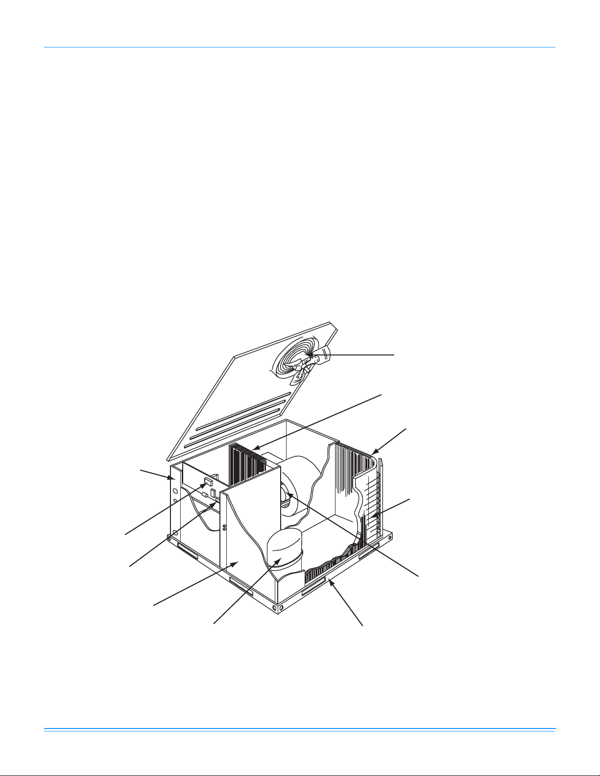
Direct Drive Condenser
Fan Motor
Highly Efficient Enhanced Copper
Tube/Aluminum Fin
Indoor Coil
Highly Efficient Enhanced Copper
Tube/Aluminum Fin
Outdoor Coil
Decorative Protective Coil Guard
(See “Features” for details)
Direct Drive Blower Motor With
Slide-Out Blower Assembly
Heavy Gauge
Removable Base Rails
High-Efficiency Compressor
Rigidly Mounted
Long-Lasting
Powder Paint Finish
Low Voltage
Terminal Block
High Voltage
Terminal Block
Back And Bottom
Return Air and Supply
Air Duct Opening
Table of Contents
Description . . . . . . . . . . . . . . . . . . . . . . . . . . . . . . . . . . . . . . . . . . . . . . . . . . . . . . . . . . . . . . . . . . . . . . . . . . . . . . . . . . . . . . . . . . . . 1
Table of Contents . . . . . . . . . . . . . . . . . . . . . . . . . . . . . . . . . . . . . . . . . . . . . . . . . . . . . . . . . . . . . . . . . . . . . . . . . . . . . . . . . . . . . . . 2
Component Location . . . . . . . . . . . . . . . . . . . . . . . . . . . . . . . . . . . . . . . . . . . . . . . . . . . . . . . . . . . . . . . . . . . . . . . . . . . . . . . . . . . . 2
Nomenclature . . . . . . . . . . . . . . . . . . . . . . . . . . . . . . . . . . . . . . . . . . . . . . . . . . . . . . . . . . . . . . . . . . . . . . . . . . . . . . . . . . . . . . . . . . 3
Heat Pump . . . . . . . . . . . . . . . . . . . . . . . . . . . . . . . . . . . . . . . . . . . . . . . . . . . . . . . . . . . . . . . . . . . . . . . . . . . . . . . . . . . . . . . . . . . . . 3
Features and Benefits . . . . . . . . . . . . . . . . . . . . . . . . . . . . . . . . . . . . . . . . . . . . . . . . . . . . . . . . . . . . . . . . . . . . . . . . . . . . . . . . . . . . 3
Guide Specifications . . . . . . . . . . . . . . . . . . . . . . . . . . . . . . . . . . . . . . . . . . . . . . . . . . . . . . . . . . . . . . . . . . . . . . . . . . . . . . . . . . . . . 5
Physical Data . . . . . . . . . . . . . . . . . . . . . . . . . . . . . . . . . . . . . . . . . . . . . . . . . . . . . . . . . . . . . . . . . . . . . . . . . . . . . . . . . . . . . . . . . . . 7
Capacity Performance . . . . . . . . . . . . . . . . . . . . . . . . . . . . . . . . . . . . . . . . . . . . . . . . . . . . . . . . . . . . . . . . . . . . . . . . . . . . . . . . . . . 9
Airflow Performance . . . . . . . . . . . . . . . . . . . . . . . . . . . . . . . . . . . . . . . . . . . . . . . . . . . . . . . . . . . . . . . . . . . . . . . . . . . . . . . . . . . . 14
Sound Performance . . . . . . . . . . . . . . . . . . . . . . . . . . . . . . . . . . . . . . . . . . . . . . . . . . . . . . . . . . . . . . . . . . . . . . . . . . . . . . . . . . . . 19
Electrical Data . . . . . . . . . . . . . . . . . . . . . . . . . . . . . . . . . . . . . . . . . . . . . . . . . . . . . . . . . . . . . . . . . . . . . . . . . . . . . . . . . . . . . . . . . 20
Weights and Dimensions . . . . . . . . . . . . . . . . . . . . . . . . . . . . . . . . . . . . . . . . . . . . . . . . . . . . . . . . . . . . . . . . . . . . . . . . . . . . . . . . 27
Component Location
Heat Pump
2 Johnson Controls Unitary Products
Page 3
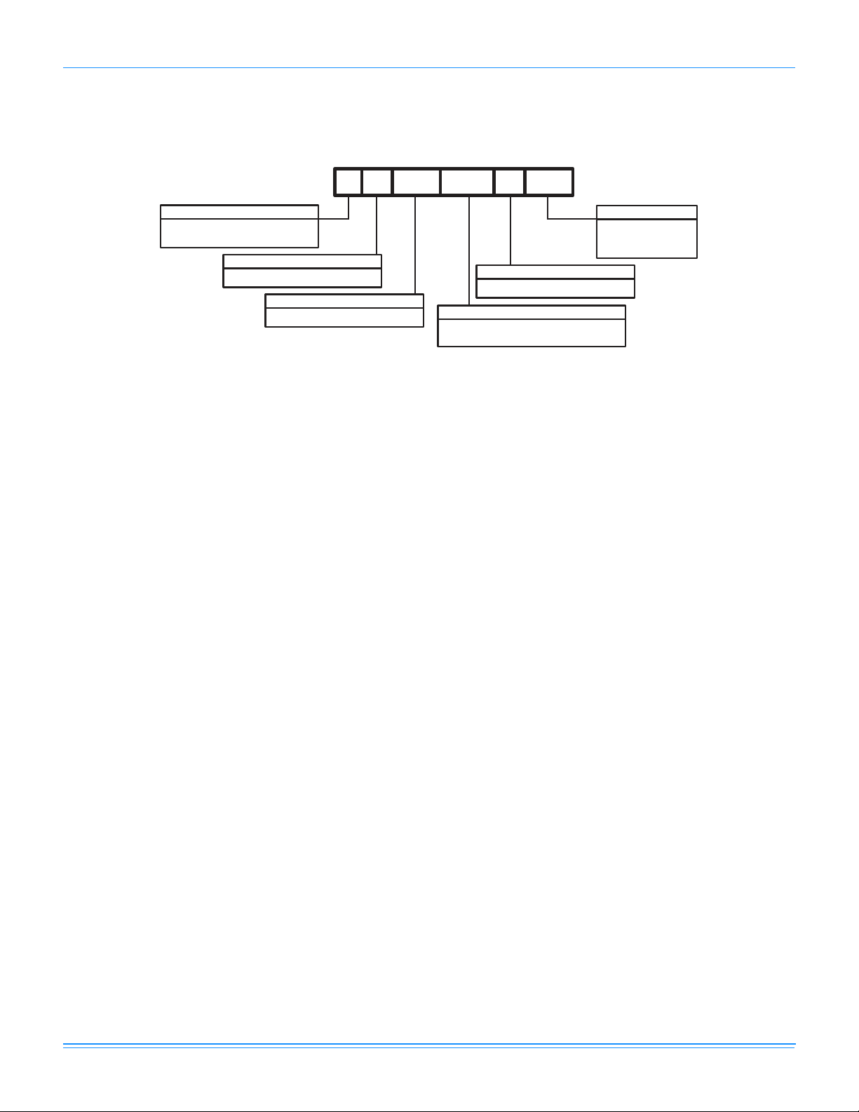
Nomenclature
B 1 024 06
A
HX
Product Category
B = Single Package Heat Pumps
(Air Cooled)
Product Generation
1 = New or Current Design
Factory Installed Gas Heat
A = No Electric Heat Installed
Product Identifier
HX = R-410A 15 SEER
024 = 24,000 BTUH
036 = 36,000 BTUH
Voltage Code
06 = 208/230-1-60
25 = 208/230-3-60
46 = 460-3-60
048 = 48,000 BTUH
060 = 60,000 BTUH
Nominal Cooling Capacity (MBH)
Heat Pump
718421-YTG-A-0811
Features and Benefits
Standard Features
• Operating Efficiency - All heat pump units provide
operating efficiencies of 15 SEER and 8.0 HSPF. All
efficiencies exceed legislated minimum levels.
• On Site Flexibility - All model sizes share a common,
compact design cabinet in a single footprint. The installer
has the flexibility of setting one curb and placing the
proper tonnage unit on that curb after the internal load has
been determined. Field convertible duct connections from
side shot to down shot allows the installer to have greater
flexibility with less inventory.
• Lower Installation Cost - Installation time and costs are
reduced by easy power and control wiring connections.
The small base dimension means less space is required
on the ground or roof, plus, the installer can fit this unit
between the wheel wells of full size pick-up truck.
• All units are completely wired, charged with R-410A and
tested prior to shipment. Unique test stations using a new
state of the art computerized process system are used to
insure product quality. Refrigerant charge and component
part numbers are verified via computers at assembly. Vital
run test statistics such as system pressure, motor
currents, air velocity and temperature, unit vibration, and
gas system safeties are monitored and recorded by the
system to insure unit performance.
• Equal size, side supply and return duct connections
allows easy hook-up of ducts to match low crawl spaces
without transition pieces.
• Utility Connections Made Easy - Electric utility
knockouts are provided through the bottom as well as the
side of the unit. Utility connections can be made quickly
and with a minimum amount of field labor. A field supplied
and field installed electrical disconnect switch must be
installed.
• Convertible Airflow Design - The bottom duct openings
are covered when they leave the factory ready to be used
for a side supply/side return application. If a bottom
supply/bottom return application is desired, you simply
remove the two panels from the bottom of the unit and
place them in the side supply/side return duct openings.
No panel cutting is required and no accessory panel is
necessary. Convertible airflow design allows maximum
field flexibility and minimum inventory.
• Condensate Pan - A non-corrosive, long-lasting, watertight pan is positioned below the evaporator coil to collect
and drain all condensate. Less collection of stagnate
condensate will build-up. The condensate pan conforms
to ASHRAE 62-89 standards (Ventilation for Acceptable
Indoor Air Quality).
• Condensate Drain - The 3/4 inch NPTF connection is
rigidly mounted to assure proper fit and leak tight seal.
• Durable Finish - The cabinet is made of pre-painted
steel. The pre-treated galvanized steel provides a better
paint to steel bond, which resists corrosion and rust creep.
Special primer formulas and matted-textured finish insure
less fading when exposed to sunlight.
• Full Perimeter Base Rails - The easily removable base
rails provide a solid foundation for the entire unit and
protects the unit during shipment. The rails provide fork lift
access from all sides, and rigging holes are also provided
so that an overhead crane can be used to place the units
on a roof. On applications where the unit is placed on a
pad, the base will keep the unit off the pad to deter
corrosion. On applications where height is limited, the inch
high base rails may be removed on location.
Johnson Controls Unitary Products 3
Page 4

718421-YTG-A-0811
• More Attractive Appearance - A single piece Water
Shed top cover containing a top discharge condenser fan
arrangement requires less square footage on installation
and provides a wider variety of installations. The one
piece design adds greater water integrity. Rounded
corners with water drip edges add to the attractive
appearance. The cabinet panels have a non-fibrous
insulation that will not release insulation fibers into
conditioned area.
• Top Discharge - The top discharge condenser fan does
not disrupt neighboring areas or dry-out vegetation
surrounding the unit. The warm air from the top mounted
fan is blown up away from the structure and any
landscaping. This allows compact location on multi-unit
applications.
• Condenser Coil Grille - All models utilize a stamped
“Louvered” design which provides superior impact
protection against smaller objects during transit and after
installation.
• Low Operating Sound Level - The upward air flow
carries the normal operating noise up and away from the
living area. The rigid top panel effectively isolates any
motor sound. Isolator mounted compressor and the
rippled fins of the condenser coil muffle the normal fan
motor and compressor operating sounds. The unique
formed base pan also aids in sound alterations with it's
Super-Structure design. This design strategically places
embossments in the pan for optimum strength and rigidity.
• Fan System - All models operate over a wide range of
design conditions with an electrically commutated fan
motor. These units easily match all types of applications
and provide greater on site flexibility to match comfort
requirement. The cooling speed is factory set and can be
field adjusted to a second speed. The heating speed is
factory set to maintain mid point rise at the units heating
input, but can be field adjusted. This allows maximum
comfort conditions.
• Simple Control Circuit - A low voltage printed circuit
board contains a diagnostic indicator light and a low
voltage terminal strip. An additional set of pin connectors
is also provided to simplify the field interface of external
controls. Mate-n-lock plug connectors are used. The
electrical control box is not located in the compressor
compartment. The controls are mounted on a Control-Tilt
control panel to allow the access cover to be removed for
trouble shooting and maintenance without affecting the
normal system operating pressures. All wiring internal to
the unit is color/number coded.
• Protected Compressor - The compressor is internally
protected against high pressure and temperature. This is
accomplished by the simultaneous operation of high
pressure relief valve and a temperature sensor which
protect the compressor if undesirable operating conditions
occur.
• Pressure Switches - High pressure and low pressure/
loss of charge switches standard in all units. When
abnormal conditions are sensed through the pressure
switches, the unit will lock out preventing any further
operation until reset or problem is corrected.
• Exclusive Coil Design - Grooved copper tubes and
enhanced aluminum fin construction improves heat
transfer for maximum efficiency and durability.
• Low Maintenance - Long life, permanently lubricated
condenser and evaporator fan motor bearings need no
annual maintenance adding greater reliability to the unit.
Blower assembly can be easily cleaned by the unique
Slip- Track slide-out blower assembly.
• Secured Service Access Ports - Protected, externally
mounted, re-usable service access ports are provided on
both the high and low lines for ease of evacuating and
charging the system. No final field mounting required.
• Easy Service Access
electrical and gas controls makes servicing easy. The
blower compartment has an additional large panel with a
built-in handle tab. Removing this panel will allow the
blower assembly to slide-out for easy removal for
maintenance and ease of trouble shooting.
• Replacement Parts - The installer requires no special
training to replace any of the components of these units
and does not need to maintain an inventory of unique
parts.
• System Integration - Each unit has the internal ability to
integrate an electronic air cleaner or humidifier to work in
conjunction with the base unit.
- A large, single panel covers the
Field Installed Accessories
• Economizer Down Discharge/Supply Kit - Modulating
integrated economizer provides simultaneous operation
between the mechanical cooling and economizer
operation. Independent blade design insures proper
control and less than 1% leak rate. Includes hood and
mesh bird screen filter integrated into the hood, dry bulb
sensor and relief damper. Separate field accessories of
single enthalpy and dual enthalpy are also available. A
built-in barometric relief of 25% is provided.
• Single Enthalpy Sensor - Sensor replaces dry bulb
sensor standard in economizer kit. Provides improved
economizer operation by sensing the dry bulb
temperature from outdoors plus the enthalpy content of
the outdoor air.
• Dual Enthalpy Sensor - Additional sensor to single
enthalpy sensor. Sensor senses both the return air
temperature dry bulb and humidity in conjunction with the
single enthalpy to determine the most economical mix.
Single Enthalpy sensor also required.
• Hail Guard Kit - Kit contains protective grilles made of
expanded aluminum with full perimeter frame. Sloped
hoods are also included to assure maximum protection.
• Anti Short Cycle Timer (BHZ Units Only) Automatically prevents the compressor from restarting for
5 minutes after cycled off.Not required if Thermostat
4 Johnson Controls Unitary Products
Page 5

718421-YTG-A-0811
2ET07700224 and 2ET04700224 are used. Standard in
all BHX units.
• Filter/Frame Kit (Single Phase Only) - Kit contains the
necessary hardware to field install return air filters into the
base unit. Pre-cut filter racks and appropriate cleanable
standard size filters are shipped in one kit. The filter rack
is suitable for either 1" or 2" filters. (1" filter is supplied)
This kit is available for single phase horizontal or vertical
duct application only. Standard in all 3 Phase models.
• Motorized Fresh Air Damper - Designed for duct
mounted side supply/return and unit mounted down
supply/return applications. Damper capable of providing
0% through 50% of outdoor air (field supplied). Closes on
power loss, includes hood and screen assembly.
• Rectangle To Round Adapters - Kit includes one supply
and one return air rectangle to round duct adapter.
Adapters are preformed and designed to fit over current
duct openings on the base unit. Transition is from side
square duct opening to 14" round duct opening.
• Roof Curbs - NRCA approved curbs provide proper fit to
base unit for rooftop installations. Curbs are designed to
be assembled through hinge pins in each corner. Kit also
provides seal strip to assure a water tight seal. 8 and 14
inch high roof curbs are available.
• Manual Outdoor Damper - Provides 0% through 50%
outdoor air capability (field adjustable). Designed for duct
mounted side supply/return applications. Includes hood
and screen assembly.
• Wall Thermostat - The units are designed to operate with
24-volt electronic and electro-mechanical thermostats. All
units can operate with single stage heat/single stage cool
thermostats - with or without the economizer.
• Low Ambient Kit - Kit provides necessary hardware to
convert unit to operate in cooling cycle down to 0º F.
Standard unit operation 45º F.
• Transformer Kit - Kit provides necessary hardware to
provide single phase models from factory furnished 40 VA
transformer capability to 75 VA transformer capability.
(Required on installations with economizer or motorized
damper.)
Guide Specifications
General
Units shall be manufactured by York International Unitary
Products Group in an ISO 9001 certified facility. YORK’s
Affinity™ package units give you the flexibility and choices you
need in today’s market. These packaged heat pumps are
designed for outdoor installation. Only utility and duct
connections are required at the point of installation.
Description
Units shall be factory-assembled, single packaged, heat pump
units, designed for outdoor mounted installation. For SEER
ratings, refer to technical literature. They shall have built in,
equal size, field convertible duct connections for down
discharge supply/return or horizontal discharge supply/return.
The units shall be factory wired, piped, charged with R-410A
Refrigerant and factory tested prior to shipment. All unit wiring
shall be both numbered and color coded. All units shall be
manufactured in a facility certified to ISO 9001 standards, and
the cooling performance shall be rated in accordance with DOE
and ARI test procedures. The heating performance shall be
rated to DOE and GAMA test procedures. Units shall be CSA
listed and classified to ANSI Z21.47/CAN/CSA 2.3 standards
and UL 1995/CAN/CSA No. 236-M90 conditions.
Unit Cabinet
Unit cabinet shall be constructed of G-90, pre-paint textured
steel, certified at 500 hours salt spray test per ASTM-B117
standards. The unit top shall be a single piece “Water Shed”
design, with drip edges and no-seam corners to provide
optimum water integrity. Unit shall have a rigidly mounted
condenser coil guard to provide protection from objects and
personnel after installation. Indoor blower section shall be
insulated with up to 3/4” thick, aluminum, foil faced insulation,
fastened to prevent insulation from entering the air stream.
Cabinet panels shall be “large” size, easily removable for
servicing and maintenance, with built-in lift handles. Unit shall
be built on a formed, “Super-Structure” design base pan, with
embossments at critical points to add strength, rigidity and aid
in minimizing sound. Full perimeter base rails shall be provided
to assure reliable transit of equipment, overhead rigging, for
truck access and proper sealing on roof curb applications. Base
rails shall be removable, when required, to lower unit height.
Filters shall be furnished and be accessible through a
removable access door, sealed airtight. Units vertical discharge
and return duct configuration shall be designed to fit between
standard 24” O.C. beams without modification to building
structure, duct work and base unit. Condensate pan shall be
internally sloped and conform to ASHRAE 62-89 self-draining
standards, with 3/4” NPTI copper, ridged mount connection.
Indoor (Evaporator) Fan Assembly
Fan shall be direct drive design. Fan wheel shall be double-inlet
type with forward-curved blades, dynamically balanced to
operate smoothly throughout the entire range of operation.
Airflow design shall be constant air volume. Bearings shall be
sealed and permanently lubricated for longer life and no
maintenance. Fan assembly shall be “Slip Track” (slide-out)
design for easy removal and cleaning.
Outdoor (Condenser) Fan Assembly
The outdoor fan shall be of the direct-driven propeller type,
discharge air vertically, have aluminum blades riveted to
corrosion resistant steel spider bracket and shall be statically
balanced for smooth operation. The outdoor fan motor shall be
totally enclosed with permanently lubricated bearings and
internally protected against overload conditions.
Johnson Controls Unitary Products 5
Page 6

718421-YTG-A-0811
Refrigerant Components
Compressors:
a. Shall be fully hermetic type, direct drive, internally
protected with internal high-pressure relief and over
temperature protection. The hermetic motor shall be
suction gas cooled and have a voltage range of +/- 10%
of the unit nameplate voltage.
b. Shall have internal isolation and sound muffling to
minimize vibration and noise, and be externally isolated
on a dedicated, independent mounting.
Coils:
a. Evaporator and condenser coils shall have aluminum
plate fins mechanically bonded to seamless internally
enhanced copper tubes with all joints brazed.
b. Evaporator coil shall be of the direct expansion, draw
through design, while condenser coil shall be draw
through design.
Refrigerant Circuit and Refrigerant Safety Components shall
include:
a. Independent fixed orifice expansion devices.
b. Filter/strainer to eliminate any foreign matter.
Electric Heating Section (Field Install Accessory)
An electric heating section, with nickel chromium elements,
shall be provided in a range of 5 thru 25 KW. The heating
section shall have a primary limit control(s) (automatic reset) to
prevent the heating element system from operating at an
excessive temperature. The Heating Section assembly shall
slide out of the unit for easy maintenance and service. Units
with Electric Heating Sections shall be wired for a single point
power supply with branch circuit fusing (where required).
6 Johnson Controls Unitary Products
Page 7
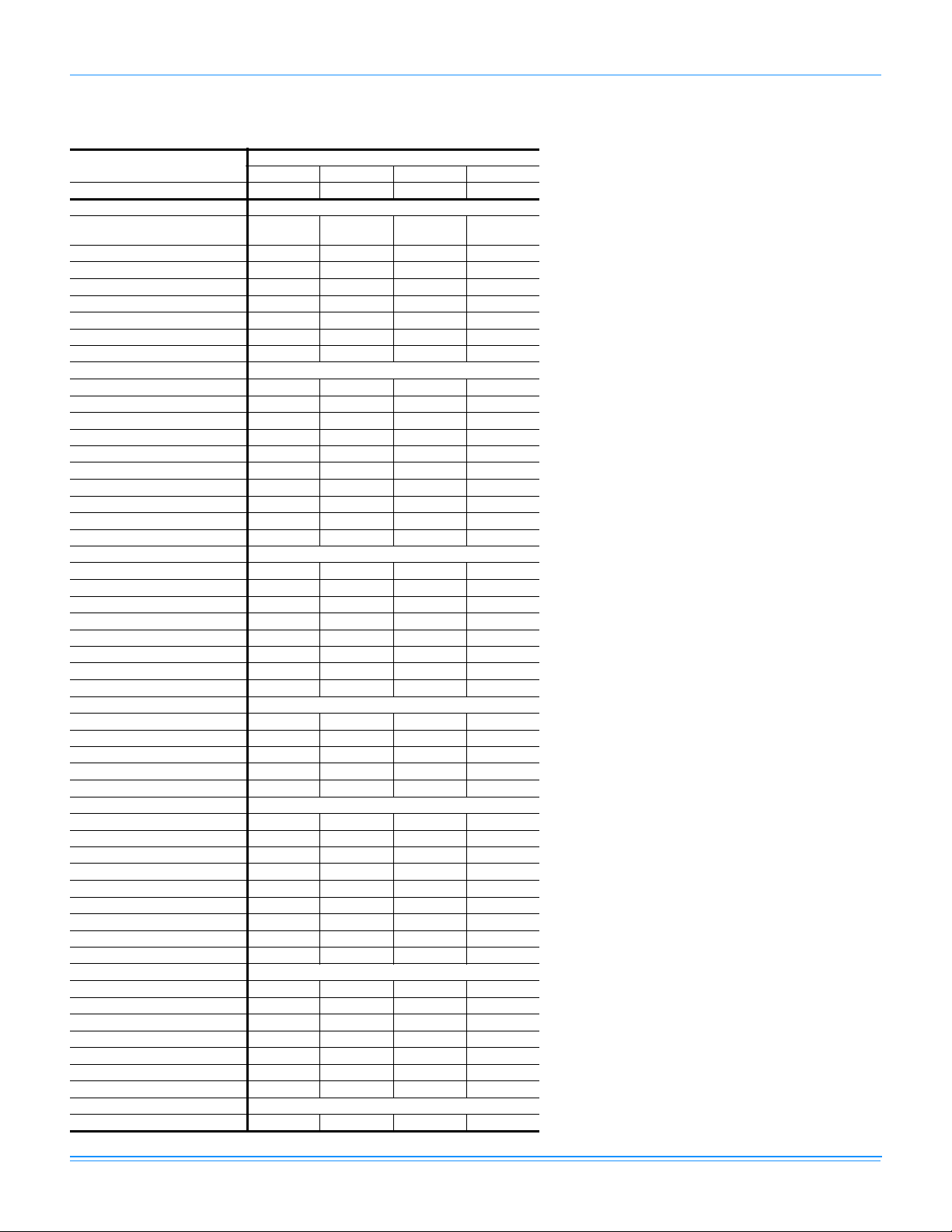
Physical Data
BHX024-060 Physical Data
Component
Nominal Tonnage 2.0 3.0 4.0 5.0
ARI COOLING PERFORMANCE
Gross Capacity @ ARI A point
(Mbh)
ARI net capacity (Mbh) 24.4 34.4 47.0 57.0
EER 12.0 11.5 11.3 11.0
SEER 16 15 15 14.5
Nominal CFM 800 1200 1600 1700
System power (KW) 2.0 3.0 4.2 5.2
Refrigerant type R410A R410A R410A R410A
Refrigerant charge (lb-oz) 7-10 10-4 12-4 12-0
ARI HEATING PERFORMANCE
47°F Capacity Rating (Mbh) 19.8 33.0 45.0 55.0
System Power (Kw/COP) 3.5 3.1 3.0 3.1
17°F Capacity Rating (Mbh) 11.1 18.9 27.2 32.4
System Power (Kw/COP) 2.1 2.0 2.1 2.1
HSPF (BTU/Watts-hr.) 8.0 8.0 8.0 8.0
DIMENSIONS (inches)
Length 49 1/8 49 1/8 49 1/8 49 1/8
Width 47 1/4 47 1/4 47 1/4 47 1/4
Height 33 1/2 33 1/2 41 1/2 41 1/2
OPERATING WT. (lbs.) 350 400 440 460
COMPRESSORS
Type Scroll 2-spd Scroll 2-spd Scroll 2-spd Scroll 2-spd
Quantity 1 1 1 1
CONDENSER COIL DATA
Face area (Sq. Ft.) 12.9 12.9 16.4 16.4
Rows 1 2 2 2
Fins per inch 20 20 20 20
Tube diameter (in.) 3/8 3/8 3/8 3/8
Refrigerant control Orifice TXV TXV TXV
EVAPORATOR COIL DATA
Face area (Sq. Ft.) 4.38 4.38 5.63 5.63
Rows 3 3 3 3
Fins per inch 15 15 16 16
Tube diameter 3/8 3/8 3/8 3/8
Refrigerant control TXV TXV TXV TXV
CONDENSER FAN DATA
Quantity of fans 1 1 1 1
Fan diameter (Inch) 22 22 22 22
Type Prop Prop Prop Prop
Drive type Direct Direct Direct Direct
Quantity of motors 1 1 1 1
Motor HP each 1/3 1/3 1/3 1/2
No. speeds 1 1 1 1
RPM 1100 1100 1100 1100
Nominal total CFM 2000 2400 3200 3400
DIRECT DRIVE EVAP FAN DATA
Quantity 1 1 1 1
Fan Size (Inch) 10 x 8 11 x 10 11 x 10 11 x 10
Type Centrifugal Centrifugal Centrifugal Centrifugal
No. speeds 1 1 1 1
Motor HP each 1/2 3/4 3/4 1
RPM Variable Variable Variable Variable
Frame size 48 48 48 48
FILTERS
Quantity - Size 2 - 22 x 14 x 1 2 - 22 x 14 x 1 2 - 22 x 14 x 1 2 - 22 x 14 x 1
BHX024 BHX036 BHX048 BHX060
24.9 35.3 49.2 58.8
Models
718421-YTG-A-0811
Johnson Controls Unitary Products 7
Page 8
718421-YTG-A-0811
BHX Unit Limitations
Size
(Tons)
024
(2.0)
036
(3.0)
048
(4.0) BHX
060
(5.0)
Unit Limitations
Model Unit Voltage
BHX 208/230-1-60 187 252 115
208/230-1-60 187 252 115
BHX
BHX
208/230-3-60 187 252 115
460-3-60 432 504 115
208/230-1-60 187 252 115
208/230-3-60 187 252 115
460-3-60 432 504 115
208/230-1-60 187 252 115
208/230-3-60 187 252 115
460-3-60 432 504 115
Applied Voltage Outdoor DB Temp
Min Max Max (°F)
8 Johnson Controls Unitary Products
Page 9
Capacity Performance
BHX024-060 Cooling Capacities
BHX024 (2.0 Ton)
Air on
Evaporator Coil
CFM
600
800
600
800
600
800
WB
(°F)
77 26.8 1.1 14.8 11.4 8.4 - - - 24.6 1.2 15.2 10.8 7.8 - - 72 24.1 1.1 18.1 15.0 12.0 9.0 - - 22.1 1.2 17.4 14.4 11.3 8.3 - 67 21.4 1.0 21.4 18.7 15.6 12.6 9.6 - 19.7 1.2 19.7 17.9 14.9 11.8 8.8 62 19.6 1.1 19.6 19.6 19.1 16.1 13.0 10.0 18.1 1.2 18.1 18.1 17.8 14.7 11.7 8.6
57 19.4 1.1 19.4 19.4 19.2 16.2 13.1 10.1 17.9 1.2 17.9 17.9 17.7 14.6 11.6 8.5
77 34.1 1.8 17.5 15.3 11.6 - - - 32.0 1.9 18.3 14.5 10.8 - - 72 31.3 1.7 23.0 19.3 15.6 12.0 - - 29.2 1.9 22.3 18.6 14.9 11.2 - 67 28.5 1.6 28.5 23.3 19.7 16.0 12.3 - 26.4 1.8 26.4 22.7 19.0 15.3 11.6 62 25.3 1.6 25.3 25.3 24.8 21.1 17.4 13.8 23.6 1.8 23.6 23.6 23.2 19.5 15.8 12.1
57 25.0 1.6 25.0 25.0 25.1 21.4 17.8 15.0 23.6 1.8 23.6 23.6 23.4 19.7 16.0 12.7
77 22.4 1.4 15.5 10.2 7.2 - - - 20.7 1.6 17.3 12.0 6.6 - - 72 20.2 1.4 16.8 13.7 10.6 7.5 - - 18.3 1.6 16.6 13.8 9.9 6.1 - 67 18.0 1.4 18.0 17.2 14.1 11.0 7.9 - 16.0 1.6 16.0 15.5 13.3 9.5 5.6 62 16.7 1.4 16.7 16.7 16.4 13.4 10.3 7.2 15.3 1.6 15.3 15.3 15.2 11.4 7.6 7.2
57 16.5 1.4 16.5 16.5 16.2 13.1 10.0 7.0 15.0 1.6 15.0 15.0 14.7 10.8 7.0 7.0
77 29.8 2.1 19.0 13.8 10.0 - - - 27.3 2.4 19.6 13.1 9.1 - - 72 27.1 2.1 21.7 17.9 14.2 10.4 - - 24.8 2.3 20.9 17.1 13.3 9.5 - 67 24.4 2.0 24.4 22.1 18.4 14.6 10.8 - 22.3 2.3 22.3 21.1 17.5 13.7 9.9 62 22.0 2.0 22.0 22.0 21.7 17.9 14.1 10.4 20.4 2.3 20.4 20.4 20.1 16.3 12.5 8.7
57 22.3 2.0 22.3 22.3 21.7 17.9 14.1 10.4 20.7 2.3 20.7 20.7 20.1 16.3 12.5 8.7
77 19.0 1.8 19.0 13.8 6.1 - - 72 16.5 1.8 16.5 13.8 9.3 4.7 - 67 13.9 1.8 13.9 13.9 12.5 7.9 3.4 62 13.9 1.8 13.9 13.9 13.9 9.4 4.8 57 13.5 1.9 13.5 13.5 13.1 8.6 4.0 77 24.8 2.6 20.1 12.4 8.3 - - 72 22.5 2.6 20.1 16.3 12.4 8.6 - 67 20.1 2.6 20.1 20.1 16.6 12.8 8.9 62 18.8 2.5 18.8 18.8 18.6 14.7 10.9 7.0
57 19.1 2.5 19.1 19.1 18.6 14.7 10.9 7.0
Net
Capacity
(MBh)
Total
1
Input
2
(kW)
Sensible Capacity (MBh)
Return Dry Bulb (°F) Return Dry Bulb (°F)
90 85 80 75 70 65 90 85 80 75 70 65
75°F 85°F
95°F 105°F
115°F
1. These capacities are Net Capacities.
2. These ratings include the compressor, condenser fan and supply air blower motors.
Temperature of Air on Condenser Coil
Net
Capacity
(MBh)
718421-YTG-A-0811
Total
1
Input
2
(kW)
Sensible Capacity (MBh)
Johnson Controls Unitary Products 9
Page 10
718421-YTG-A-0811
BHX036 (3.0 Ton)
Air on
Evaporator Coil
CFM
900
1200
900
1200
900
1200
WB
(°F)
77 36.8 1.5 20.7 16.2 11.9 - - - 34.2 1.7 21.5 15.2 11.0 - - 72 33.8 1.5 25.7 21.5 17.3 13.1 - - 31.0 1.8 24.7 20.5 16.3 12.1 - 67 30.8 1.5 30.8 26.8 22.6 18.4 14.2 - 27.9 1.8 27.9 25.8 21.6 17.4 13.2 62 28.3 1.5 28.3 28.3 28.3 24.1 19.8 15.6 26.1 1.8 26.1 26.1 26.1 21.9 17.7 13.5
57 28.1 1.5 28.1 28.1 28.2 23.9 19.7 15.5 26.3 1.7 26.3 26.3 26.2 22.0 17.8 13.6
77 49.8 2.7 24.5 20.9 15.9 - - - 46.0 2.9 24.9 19.4 14.5 - - 72 44.7 2.6 32.0 27.1 22.1 17.2 - - 41.5 2.8 30.9 26.0 21.0 16.0 - 67 39.5 2.4 39.5 33.3 28.4 23.4 18.5 - 37.0 2.7 37.0 32.5 27.5 22.5 17.6 62 36.5 2.3 36.5 36.5 35.8 30.9 25.9 21.0 34.2 2.6 34.2 34.2 33.9 28.9 23.9 18.9
57 36.6 2.3 36.6 36.6 36.5 31.5 26.6 23.9 34.3 2.6 34.3 34.3 34.2 29.2 24.2 20.4
77 31.5 2.0 22.4 14.2 10.1 - - - 28.3 2.2 23.1 14.7 9.0 - - 72 28.2 2.0 23.7 19.5 15.3 11.2 - - 25.3 2.3 22.8 18.5 14.3 10.1 - 67 25.0 2.0 25.0 24.8 20.6 16.4 12.2 - 22.4 2.3 22.4 22.3 19.6 15.3 11.1 62 24.0 2.0 24.0 24.0 24.0 19.8 15.7 11.5 21.7 2.2 21.7 21.7 21.8 17.5 13.3 9.0
57 24.5 2.0 24.5 24.5 24.2 20.0 15.8 11.7 22.4 2.2 22.4 22.4 22.0 17.8 13.6 9.3
77 42.1 3.1 25.3 18.0 13.0 - - - 37.9 3.4 25.6 17.1 12.2 - - 72 38.2 3.0 29.9 24.8 19.8 14.8 - - 34.6 3.4 28.5 23.6 18.7 13.8 - 67 34.4 3.0 34.4 31.7 26.7 21.7 16.7 - 31.4 3.3 31.4 30.0 25.2 20.3 15.4 62 31.9 2.9 31.9 31.9 31.9 26.9 21.9 16.9 29.5 3.2 29.5 29.5 29.5 24.6 19.7 14.8
57 31.9 2.9 31.9 31.9 31.9 26.9 21.9 16.9 29.6 3.2 29.6 29.6 29.6 24.7 19.8 14.9
77 25.0 2.5 23.8 15.2 8.0 - - 72 22.5 2.5 21.9 17.6 13.3 9.0 - 67 19.9 2.5 19.9 19.9 18.5 14.2 9.9 62 19.5 2.5 19.5 19.5 19.5 15.2 10.9 6.6
57 20.4 2.5 20.4 20.4 19.9 15.6 11.3 7.0
77 33.7 3.8 25.8 16.3 11.4 - - 72 31.0 3.7 27.1 22.3 17.5 12.7 - 67 28.4 3.7 28.4 28.4 23.7 18.9 14.1 62 27.1 3.6 27.1 27.1 27.1 22.4 17.6 12.8
57 27.3 3.6 27.3 27.3 27.3 22.5 17.7 12.9
Net
Capacity
(MBh)
Total
1
Input
2
(kW)
Sensible Capacity (MBh)
Return Dry Bulb (°F) Return Dry Bulb (°F)
90 85 80 75 70 65 90 85 80 75 70 65
75°F 85°F
95°F 105°F
115°F
1. These capacities are Net Capacities.
2. These ratings include the compressor, condenser fan and supply air blower motors.
Temperature of Air on Condenser Coil
Net
Capacity
(MBh)
Total
1
Input
2
(kW)
Sensible Capacity (MBh)
10 Johnson Controls Unitary Products
Page 11

BHX048 (4.0 Ton)
Air on
Evaporator Coil
CFM
1050
1600
1050
1600
1050
1600
WB
(°F)
77 47.4 2.2 25.0 20.4 15.4 - - - 43.6 2.4 24.5 19.1 14.1 - - 72 42.5 2.2 31.3 26.3 21.3 16.3 - - 39.6 2.5 30.0 25.0 19.9 14.9 - 67 37.6 2.3 37.6 32.1 27.1 22.1 17.1 - 35.5 2.6 35.5 30.8 25.8 20.8 15.8 62 33.3 2.5 33.3 33.3 31.9 26.9 21.9 16.9 31.0 2.8 31.0 31.0 30.1 25.1 20.0 15.0
57 34.0 2.3 34.0 34.0 33.7 28.6 23.6 18.6 32.0 2.6 32.0 32.0 31.7 26.7 21.7 16.6
77 66.1 3.9 29.2 24.8 18.0 - - - 62.6 4.1 31.5 24.3 17.4 - - 72 60.2 3.7 41.7 34.9 28.0 21.1 - - 56.7 3.9 41.2 34.2 27.2 20.2 - 67 54.3 3.5 54.3 44.9 38.0 31.1 24.3 - 50.8 3.8 50.8 44.0 37.0 30.0 23.1 62 48.4 3.6 48.4 48.4 49.4 42.5 35.6 28.7 46.5 3.9 46.5 46.5 46.5 39.5 32.6 25.6
57 53.5 3.6 53.5 53.5 48.8 41.9 35.0 32.8 50.5 3.9 50.5 50.5 46.0 39.0 32.1 27.4
77 39.9 2.7 24.0 17.8 12.7 - - - 36.8 3.1 23.8 16.4 11.6 - - 72 36.6 2.8 28.7 23.7 18.6 13.6 - - 33.5 3.1 27.0 22.3 17.5 12.8 - 67 33.4 2.8 33.4 29.6 24.5 19.5 14.5 - 30.1 3.1 30.1 28.1 23.4 18.7 14.0 62 28.8 3.1 28.8 28.8 28.2 23.2 18.1 13.1 26.6 3.4 26.6 26.6 26.1 21.3 16.6 11.9
57 30.1 2.8 30.1 30.1 29.7 24.7 19.7 14.6 27.9 3.2 27.9 27.9 27.5 22.8 18.1 13.4
77 59.0 4.2 33.8 23.9 16.8 - - - 53.4 4.6 34.7 22.5 15.2 - - 72 53.2 4.2 40.6 33.5 26.4 19.3 - - 48.4 4.6 39.1 31.9 24.7 17.6 - 67 47.4 4.2 47.4 43.1 36.0 29.0 21.9 - 43.5 4.6 43.5 41.3 34.3 27.1 20.0 62 44.7 4.2 44.7 44.7 43.7 36.6 29.5 22.4 42.1 4.5 42.1 42.1 40.3 33.2 26.0 18.8
57 47.5 4.2 47.5 47.5 43.2 36.2 29.1 22.0 44.3 4.5 44.3 44.3 40.1 33.0 25.8 18.7
77 33.8 3.4 23.6 15.0 10.5 - - 72 30.4 3.4 25.3 20.8 16.4 12.0 - 67 26.9 3.5 26.9 26.7 22.3 17.9 13.5 62 24.4 3.7 24.4 24.4 23.9 19.5 15.1 10.7
57 25.7 3.5 25.7 25.7 25.3 20.9 16.5 12.1
77 47.8 4.9 35.5 21.1 13.6 - - 72 43.7 4.9 37.5 30.3 23.1 15.8 - 67 39.5 5.0 39.5 39.5 32.5 25.3 18.1 62 39.6 4.9 39.6 39.6 37.0 29.7 22.5 15.3
57 41.2 4.9 41.2 41.2 37.0 29.8 22.6 15.4
Net
Capacity
(MBh)
Total
1
Input
2
(kW)
Sensible Capacity (MBh)
Return Dry Bulb (°F) Return Dry Bulb (°F)
90 85 80 75 70 65 90 85 80 75 70 65
75°F 85°F
95°F 105°F
115°F
1. These capacities are Net Capacities.
2. These ratings include the compressor, condenser fan and supply air blower motors.
Temperature of Air on Condenser Coil
Net
Capacity
(MBh)
718421-YTG-A-0811
Total
1
Input
2
(kW)
Sensible Capacity (MBh)
Johnson Controls Unitary Products 11
Page 12

718421-YTG-A-0811
BHX060 (5.0 Ton)
Air on
Evaporator Coil
CFM
1200
1700
1200
1700
1200
1700
WB
(°F)
77 55.4 2.6 27.9 22.7 17.5 - - - 52.0 3.0 26.9 21.7 16.4 - - 72 50.6 2.7 34.5 29.3 24.1 18.9 - - 47.3 3.0 33.4 28.1 22.9 17.6 - 67 45.8 2.7 41.0 35.8 30.7 25.5 20.3 - 42.6 3.0 39.8 34.6 29.3 24.1 18.8 62 40.8 2.6 40.8 40.8 37.1 31.9 26.8 21.6 38.3 3.0 38.3 38.3 35.9 30.7 25.4 20.2
57 40.1 2.6 40.1 40.1 39.4 34.2 29.1 23.9 38.0 3.1 38.0 38.0 37.2 32.0 26.7 21.5
77 77.6 4.5 37.0 30.4 23.7 - - - 72.6 4.9 36.1 29.4 22.6 - - 72 71.5 4.4 46.1 39.5 32.9 26.2 - - 66.9 4.8 45.0 38.3 31.5 24.8 - 67 65.4 4.2 55.3 48.6 42.0 35.4 28.7 - 61.2 4.7 54.0 47.2 40.5 33.7 27.0 62 59.3 4.1 59.3 59.3 53.5 46.8 40.2 33.6 55.6 4.5 55.6 55.6 51.2 44.4 37.7 30.9
57 57.6 4.1 57.6 57.6 56.3 49.7 43.1 40.3 54.6 4.6 54.6 54.6 53.3 46.5 39.8 34.9
77 48.5 3.5 25.9 20.6 15.3 - - - 44.5 3.9 23.4 18.6 14.0 - - 72 44.0 3.4 32.2 26.9 21.6 16.4 - - 40.2 3.9 29.4 24.8 20.2 15.6 - 67 39.4 3.4 38.6 33.3 28.0 22.7 17.4 - 35.8 3.9 35.4 31.0 26.4 21.8 17.2 62 35.8 3.4 35.8 35.8 34.7 29.4 24.1 18.8 33.0 3.8 33.0 33.0 32.5 27.9 23.3 18.7
57 35.8 3.5 35.8 35.8 35.0 29.7 24.4 19.1 32.9 4.0 32.9 32.9 32.0 27.4 22.8 18.2
77 67.5 5.3 35.2 28.4 21.5 - - - 62.6 6.0 33.7 26.1 19.2 - - 72 62.3 5.2 44.0 37.1 30.2 23.4 - - 57.6 5.8 42.1 35.2 28.3 21.5 - 67 57.1 5.1 52.7 45.8 39.0 32.1 25.2 - 52.7 5.7 50.5 44.3 37.4 30.6 23.7 62 51.9 5.0 51.9 51.9 48.9 42.0 35.2 28.3 48.3 5.6 48.3 48.3 46.5 39.7 32.8 25.9
57 51.6 5.1 51.6 51.6 50.2 43.4 36.5 29.6 48.1 5.7 48.1 48.1 46.8 39.9 33.0 26.1
77 40.5 4.4 21.0 16.6 12.7 - - 72 36.3 4.4 26.6 22.7 18.8 14.9 - 67 32.2 4.3 32.2 28.8 24.9 21.0 17.1 62 30.2 4.3 30.2 30.2 30.2 26.3 22.4 18.5
57 30.0 4.6 30.0 30.0 29.1 25.2 21.3 17.4
77 57.7 6.7 32.1 23.8 17.0 - - 72 53.0 6.5 40.2 33.3 26.4 19.5 - 67 48.3 6.2 48.3 42.8 35.9 29.0 22.1 62 44.6 6.1 44.6 44.6 44.2 37.3 30.4 23.5
57 44.6 6.3 44.6 44.6 43.3 36.4 29.5 22.6
Net
Capacity
(MBh)
Total
1
Input
2
(kW)
Sensible Capacity (MBh)
Return Dry Bulb (°F) Return Dry Bulb (°F)
90 85 80 75 70 65 90 85 80 75 70 65
75°F 85°F
95°F 105°F
115°F
1. These capacities are Net Capacities.
2. These ratings include the compressor, condenser fan and supply air blower motors.
Temperature of Air on Condenser Coil
Net
Capacity
(MBh)
Total
1
Input
2
(kW)
Sensible Capacity (MBh)
12 Johnson Controls Unitary Products
Page 13

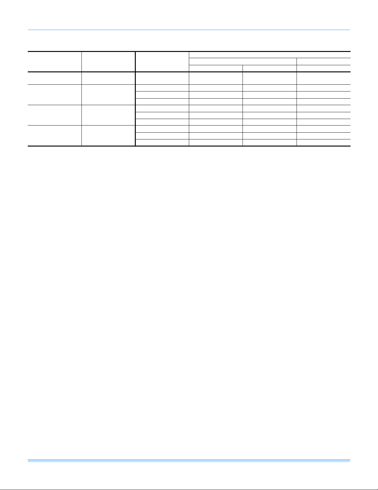
Heating Capacities
BHX024-060
Size
(Tons)
024
(2.0)
036
(3.0)
048
(4.0)
060
(5.0)
1. These Capacities are net capacities - the indoor motor heat has been added.
2. These power inputs are total power inputs - the indoor motor watts have been added.
Air Over Evaporator
Coil
CFM DB (°F
55
650
800
900
1100
1200
1600
1200
1700
70
80
55
70
80
55
70
80
55
70
80
55
70
80
55
70
80
55
70
80
55
70
80
1
Capacity
& kW
2
) -10 0 10 20 30 40 50 60
MBH 5.52 6.55 7.81 9.35 11.24 13.55 16.38 19.85
KW 0.89 0.90 0.91 0.92 0.93 0.94 0.96 0.97
MBH 4.58 5.61 6.87 8.41 10.30 12.61 15.44 18.91
KW 1.07 1.08 1.09 1.10 1.11 1.13 1.14 1.15
MBH 3.55 4.58 5.84 7.38 9.27 11.58 14.41 17.88
KW 1.22 1.23 1.24 1.25 1.26 1.27 1.29 1.30
MBH 11.33 12.80 14.53 16.54 18.91 21.67 24.91 28.71
KW 1.03 1.07 1.13 1.19 1.25 1.31 1.37 1.43
MBH 8.60 10.07 11.79 13.81 16.17 18.94 22.18 25.97
KW 1.25 1.28 1.34 1.40 1.47 1.53 1.59 1.65
MBH 7.49 8.96 10.68 12.70 15.06 17.83 21.07 24.87
KW 1.44 1.48 1.54 1.60 1.66 1.72 1.78 1.84
MBH 10.90 12.40 14.14 16.14 18.46 21.15 24.25 27.84
KW 1.44 1.48 1.53 1.57 1.62 1.67 1.72 1.77
MBH 9.57 11.07 12.80 14.81 17.13 19.81 22.92 26.51
KW 1.73 1.77 1.82 1.86 1.91 1.96 2.01 2.06
MBH 8.77 10.27 12.01 14.01 16.33 19.01 22.12 25.71
KW 2.05 2.10 2.14 2.19 2.23 2.28 2.33 2.38
MBH 13.92 16.10 18.68 21.75 25.38 29.69 34.80 40.85
KW 1.68 1.77 1.86 1.96 2.06 2.16 2.27 2.39
MBH 11.75 13.93 16.51 19.58 23.21 27.52 32.63 38.68
KW 2.16 2.25 2.34 2.44 2.54 2.64 2.75 2.87
MBH 7.25 9.43 12.02 15.08 18.72 23.02 28.13 34.19
KW 2.08 2.17 2.27 2.36 2.46 2.57 2.68 2.79
MBH 13.84 15.99 18.53 21.51 25.01 29.13 33.96 39.65
KW 1.39 1.56 1.74 1.91 2.08 2.26 2.43 2.60
MBH 12.34 14.50 17.04 20.02 23.52 27.63 32.47 38.15
KW 1.88 2.06 2.23 2.40 2.58 2.75 2.92 3.09
MBH 11.41 13.57 16.11 19.09 22.59 26.71 31.54 37.22
KW 2.36 2.53 2.71 2.88 3.05 3.23 3.40 3.57
MBH 15.52 18.56 22.22 26.61 31.88 38.22 45.83 54.96
KW 1.84 2.05 2.27 2.51 2.77 3.06 3.37 3.70
MBH 15.13 18.17 21.83 26.22 31.49 37.83 45.44 54.57
KW 2.43 2.63 2.86 3.10 3.36 3.64 3.95 4.28
MBH 14.45 17.49 21.15 25.54 30.81 37.15 44.76 53.89
KW 3.09 3.30 3.52 3.76 4.02 4.30 4.61 4.95
MBH 13.78 16.37 19.51 23.30 27.90 33.46 40.20 48.36
KW 1.59 1.77 1.97 2.18 2.41 2.65 2.91 3.20
MBH 12.28 14.87 18.00 21.80 26.39 31.96 38.69 46.85
KW 2.32 2.50 2.70 2.91 3.14 3.38 3.64 3.93
MBH 11.43 14.02 17.16 20.95 25.55 31.11 37.85 46.01
KW 2.98 3.16 3.35 3.56 3.79 4.03 4.30 4.58
MBH 22.93 26.78 31.33 36.69 43.03 50.51 59.34 69.77
KW 1.37 1.70 2.07 2.49 2.97 3.51 4.12 4.81
MBH 21.30 25.15 29.70 35.06 41.40 48.88 57.71 68.14
KW 2.49 2.82 3.19 3.61 4.09 4.63 5.24 5.93
MBH 19.88 23.73 28.27 33.64 39.98 47.46 56.29 66.72
KW 3.43 3.76 4.13 4.55 5.03 5.57 6.18 6.87
Outdoor Temperature (°F @ 72% RH)
718421-YTG-A-0811
Johnson Controls Unitary Products 13
Page 14

718421-YTG-A-0811
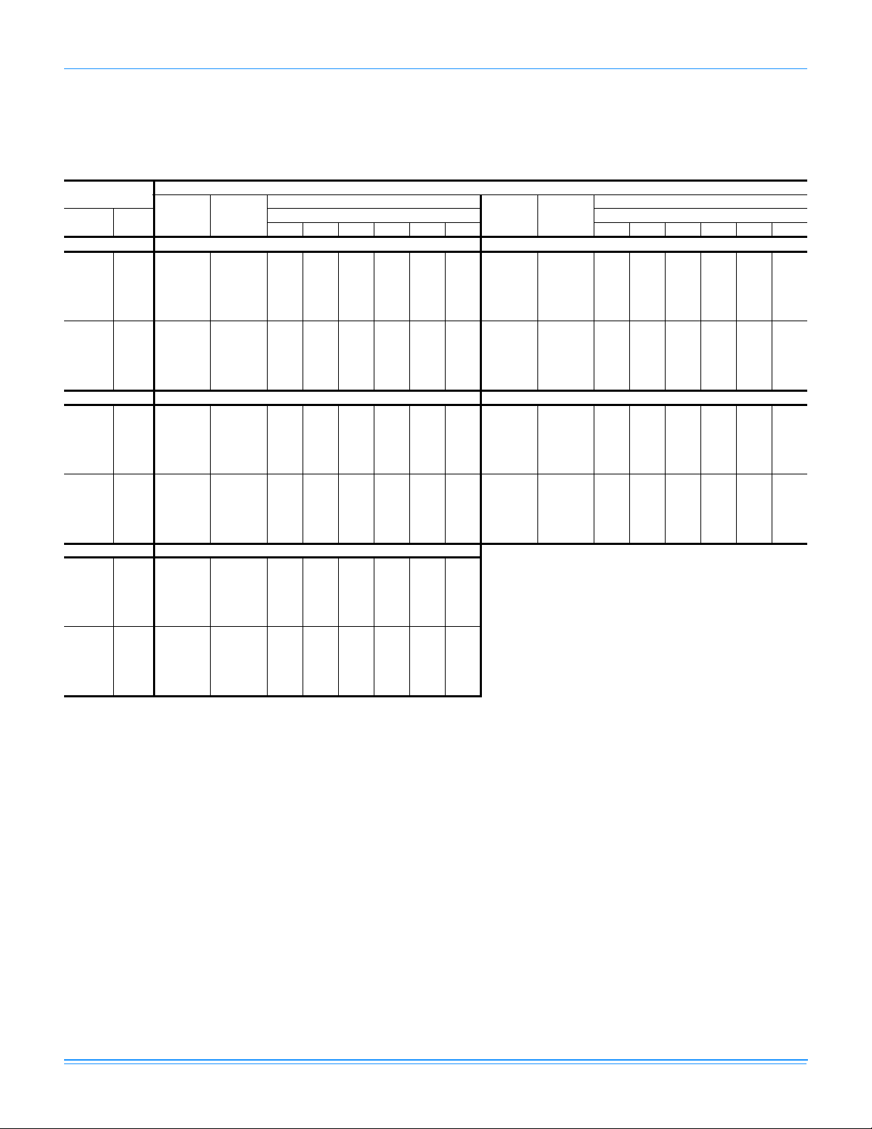
Airflow Performance
Side Duct Application
BHX024-060
Size
Model Mode
(Tons)
Low
Cool
High
Heat
Pump
024
BHX
(2.0)
036
(3.0)
Heat
Cool
BHX
Heat
Heat
Pump
+
Aux.
Heat
Low
High
Heat
Pump
Heat
Pump
+
Aux.
Heat
Thermostat
Input
Y1 COOL-A 600 58 74 91 108 126 143 161 179 197
Y1 COOL-B 450 39 53 68 84 100 117 134 152 170
Y1 COOL-C 525 47 63 79 95 112 129 146 164 182
Y1 COOL-D 675 71 89 106 124 143 161 179 198 217
Y1+Y2 COOL-A 800 99 118 137 157 177 197 217 238 259
Y1+Y2 COOL-B 600 58 74 91 108 126 143 161 179 197
Y1+Y2 COOL-C 700 76 94 112 130 149 167 186 205 224
Y1+Y2 COOL-D 900 127 146 167 188 209 231 254 277 301
Y1 COOL-A 800 99 118 137 157 177 197 217 238 259
Y1 COOL-B 600 58 74 91 108 126 143 161 179 197
Y1 COOL-C 700 76 94 112 130 149 167 186 205 224
Y1 COOL-D 900 127 146 167 188 209 231 254 277 301
Y1+W1 COOL-A; HEAT-A 800 99 118 137 157 - - - - Y1+W1 COOL-A; HEAT-B 800 99 118 137 157 - - - - Y1+W1 COOL-A; HEAT-C 880 121 140 160 181 - - - - Y1+W1 COOL-A; HEAT-D 800 99 118 137 157 - - - - Y1+W1 COOL-B; HEAT-A 800 99 118 137 157 - - - - Y1+W1 COOL-B; HEAT-B 720 80 98 117 135 - - - - Y1+W1 COOL-B; HEAT-C 880 121 140 160 181 - - - - Y1+W1 COOL-B; HEAT-D 800 99 118 137 157 - - - - Y1+W1 COOL-C; HEAT-A 800 99 118 137 157 - - - - Y1+W1 COOL-C; HEAT-B 720 80 98 117 135 - - - - Y1+W1 COOL-C; HEAT-C 880 121 140 160 181 - - - - Y1+W1 COOL-C; HEAT-D 800 99 118 137 157 - - - - Y1+W1 COOL-D; HEAT-A 900 127 146 167 188 - - - - Y1+W1 COOL-D; HEAT-B 900 127 146 167 188 - - - - Y1+W1 COOL-D; HEAT-C 900 127 146 167 188 - - - - Y1+W1 COOL-D; HEAT-D 900 127 146 167 188 - - - - -
Y1 COOL-A 900 140 165 191 217 245 273 303 333 364
Y1 COOL-B 750 98 122 146 171 196 222 248 275 302
Y1 COOL-C 825 118 142 167 192 219 246 273 302 331
Y1 COOL-D 975 163 190 217 246 275 305 336 368 400
Y1+Y2 COOL-A 1200 245 279 314 349 385 421 457 494 531
Y1+Y2 COOL-B 1000 171 199 227 256 285 316 347 380 413
Y1+Y2 COOL-C 1100 206 237 268 300 332 365 399 434 468
Y1+Y2 COOL-D 1300 286 326 366 405 444 483 522 562 600
Y1 COOL-A 1200 245 279 314 349 385 421 457 494 531
Y1 COOL-B 1000 171 199 227 256 285 316 347 380 413
Y1 COOL-C 1100 206 237 268 300 332 365 399 434 468
Y1 COOL-D 1300 286 326 366 405 444 483 522 562 600
Y1+W1 COOL-A; HEAT-A 1200 245 279 314 349 - - - - Y1+W1 COOL-A; HEAT-B 1200 245 279 314 349 - - - - Y1+W1 COOL-A; HEAT-C 1320 295 336 376 417 - - - - Y1+W1 COOL-A; HEAT-D 1200 245 279 314 349 - - - - Y1+W1 COOL-B; HEAT-A 1200 245 279 314 349 - - - - Y1+W1 COOL-B; HEAT-B 1080 199 229 259 290 - - - - Y1+W1 COOL-B; HEAT-C 1320 295 336 376 417 - - - - Y1+W1 COOL-B; HEAT-D 1200 245 279 314 349 - - - - Y1+W1 COOL-C; HEAT-A 1200 245 279 314 349 - - - - Y1+W1 COOL-C; HEAT-B 1100 206 237 268 300 - - - - Y1+W1 COOL-C; HEAT-C 1320 295 336 376 417 - - - - Y1+W1 COOL-C; HEAT-D 1200 245 279 314 349 - - - - Y1+W1 COOL-D; HEAT-A 1300 286 326 366 405 - - - - Y1+W1 COOL-D; HEAT-B 1300 286 326 366 405 - - - - Y1+W1 COOL-D; HEAT-C 1320 295 336 376 417 - - - - Y1+W1 COOL-D; HEAT-D 1300 286 326 366 405 - - - - -
Speed
Tap
CFM
0.20.30.40.50.60.70.80.91.0
Watts Watts Watts Watts Watts Watts Watts Watts Watts
External Static Pressure (Inch Water Gauge)
14 Johnson Controls Unitary Products
Page 15

BHX024-060 (Continued)
Size
Model Mode
(Tons)
Low
Cool
High
Heat
Pump
048
BHX
(4.0)
060
(5.0)
Heat
Cool
BHX
Heat
Heat
Pump
+
Aux.
Heat
Low
High
Heat
Pump
Heat
Pump
+
Aux.
Heat
718421-YTG-A-0811
Thermostat
Input
Y1 COOL-A 1050 184 216 248 280 313 346 380 414 448
Y1 COOL-B 918 138 166 194 224 254 286 318 351 385
Y1 COOL-C 984 160 190 220 251 282 315 348 381 416
Y1 COOL-D 1115 210 243 277 311 345 379 414 449 484
Y1+Y2 COOL-A 1600 448 500 551 600 647 693 736 779 819
Y1+Y2 COOL-B 1400 338 383 426 468 509 549 589 627 664
Y1+Y2 COOL-C 1500 391 439 486 532 576 618 660 700 739
Y1+Y2 COOL-D 1700 508 565 620 672 723 772 818 863 905
Y1 COOL-A 1600 448 500 551 600 647 693 736 779 819
Y1 COOL-B 1400 338 383 426 468 509 549 589 627 664
Y1 COOL-C 1500 391 439 486 532 576 618 660 700 739
Y1 COOL-D 1700 508 565 620 672 723 772 818 863 905
Y1+W1 COOL-A; HEAT-A 1600 448 500 551 600 647 - - - Y1+W1 COOL-A; HEAT-B 1600 448 500 551 600 647 - - - Y1+W1 COOL-A; HEAT-C 1760 546 606 663 718 771 - - - Y1+W1 COOL-A; HEAT-D 1600 448 500 551 600 647 - - - Y1+W1 COOL-B; HEAT-A 1600 448 500 551 600 647 - - - Y1+W1 COOL-B; HEAT-B 1440 359 405 449 493 535 - - - Y1+W1 COOL-B; HEAT-C 1760 546 606 663 718 771 - - - Y1+W1 COOL-B; HEAT-D 1600 448 500 551 600 647 - - - Y1+W1 COOL-C; HEAT-A 1600 448 500 551 600 647 - - - Y1+W1 COOL-C; HEAT-B 1500 391 439 486 532 576 - - - Y1+W1 COOL-C; HEAT-C 1760 546 606 663 718 771 - - - Y1+W1 COOL-C; HEAT-D 1600 448 500 551 600 647 - - - Y1+W1 COOL-D; HEAT-A 1700 508 565 620 672 723 - - - Y1+W1 COOL-D; HEAT-B 1700 508 565 620 672 723 - - - Y1+W1 COOL-D; HEAT-C 1760 546 606 663 718 771 - - - Y1+W1 COOL-D; HEAT-D 1700 508 565 620 672 723 - - - -
Y1 COOL-A 1200 138 176 211 244 275 303 329 352 374
Y1 COOL-B 1130 61 98 133 163 190 213 232 247 260
Y1 COOL-C 1270 208 246 283 318 353 386 418 448 478
Y1 COOL-D 1340 272 310 348 386 423 460 497 533 570
Y1+Y2 COOL-A 1700 487 531 575 621 668 716 765 816 867
Y1+Y2 COOL-B 1600 446 487 530 574 619 666 714 763 814
Y1+Y2 COOL-C 1800 514 560 607 654 701 749 798 847 897
Y1+Y2 COOL-D 1900 526 576 624 672 720 766 813 859
Y1 COOL-A 1700 487 531 575 621 668 716 765 816 867
Y1 COOL-B 1600 446 487 530 574 619 666 714 763 814
Y1 COOL-C 1800 514 560 607 654 701 749 798 847 897
Y1 COOL-D 1900 526 576 624 672 720 766 813 859 -
Y1+W1 COOL-A; HEAT-A 1900 526 576 624 672 720 - - - Y1+W1 COOL-A; HEAT-B 1975 526 578 628 677 723 - - - Y1+W1 COOL-A; HEAT-C 2150 495 554 607 656 699 - - - Y1+W1 COOL-A; HEAT-D 2070 515 570 622 671 716 - - - Y1+W1 COOL-B; HEAT-A 1900 526 576 624 672 720 - - - Y1+W1 COOL-B; HEAT-B 1975 526 578 628 677 723 - - - Y1+W1 COOL-B; HEAT-C 2150 495 554 607 656 699 - - - Y1+W1 COOL-B; HEAT-D 2070 515 570 622 671 716 - - - Y1+W1 COOL-C; HEAT-A 1900 526 576 624 672 720 - - - Y1+W1 COOL-C; HEAT-B 1975 526 578 628 677 723 - - - Y1+W1 COOL-C; HEAT-C 2150 495 554 607 656 699 - - - Y1+W1 COOL-C; HEAT-D 2070 515 570 622 671 716 - - - Y1+W1 COOL-D; HEAT-A 1900 526 576 624 672 720 - - - Y1+W1 COOL-D; HEAT-B 1975 526 578 628 677 723 - - - Y1+W1 COOL-D; HEAT-C 2150 495 554 607 656 699 - - - Y1+W1 COOL-D; HEAT-D 2070 515 570 622 671 716 - - - -
Speed
Tap
CFM
0.20.30.40.50.60.70.80.91.0
Watts Watts Watts Watts Watts Watts Watts Watts Watts
External Static Pressure (Inch Water Gauge)
Johnson Controls Unitary Products 15
Page 16

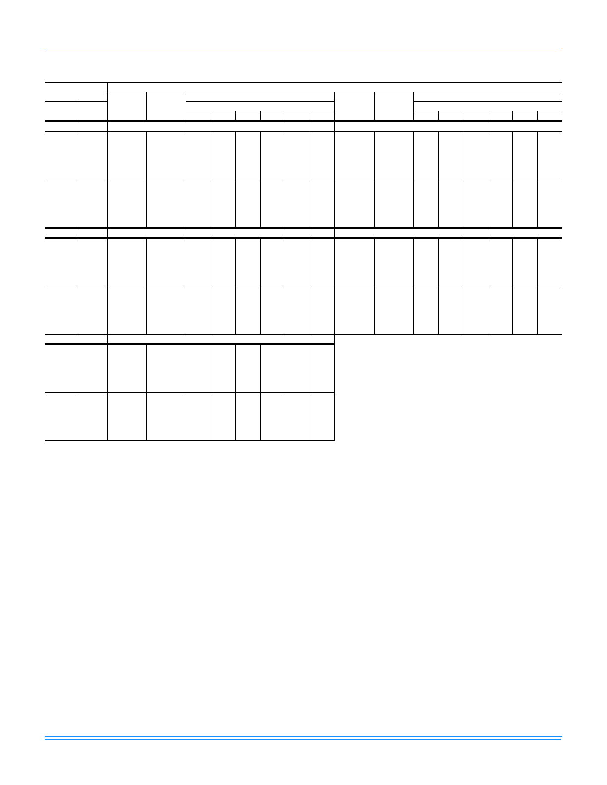
718421-YTG-A-0811
Bottom Duct Application
BHX024-060
Size
Model Mode
(Tons)
Low
Cool
High
Heat
Pump
024
BHX
(2.0)
036
(3.0)
Heat
Cool
BHX
Heat
Heat
Pump
+
Aux.
Heat
Low
High
Heat
Pump
Heat
Pump
+
Aux.
Heat
Thermostat
Input
Y1 COOL-A 600 58 74 91 108 126 143 161 179 197
Y1 COOL-B 450 39 53 68 84 100 117 134 152 170
Y1 COOL-C 525 47 63 79 95 112 129 146 164 182
Y1 COOL-D 675 71 89 106 124 143 161 179 198 217
Y1+Y2 COOL-A 800 99 118 137 157 177 197 217 238 259
Y1+Y2 COOL-B 600 58 74 91 108 126 143 161 179 197
Y1+Y2 COOL-C 700 76 94 112 130 149 167 186 205 224
Y1+Y2 COOL-D 900 127 146 167 188 209 231 254 277 301
Y1 COOL-A 800 99 118 137 157 177 197 217 238 259
Y1 COOL-B 600 58 74 91 108 126 143 161 179 197
Y1 COOL-C 700 76 94 112 130 149 167 186 205 224
Y1 COOL-D 900 127 146 167 188 209 231 254 277 301
Y1+W1 COOL-A; HEAT-A 800 99 118 137 157 - - - - Y1+W1 COOL-A; HEAT-B 800 99 118 137 157 - - - - Y1+W1 COOL-A; HEAT-C 880 121 140 160 181 - - - - Y1+W1 COOL-A; HEAT-D 800 99 118 137 157 - - - - Y1+W1 COOL-B; HEAT-A 800 99 118 137 157 - - - - Y1+W1 COOL-B; HEAT-B 720 80 98 117 135 - - - - Y1+W1 COOL-B; HEAT-C 880 121 140 160 181 - - - - Y1+W1 COOL-B; HEAT-D 800 99 118 137 157 - - - - Y1+W1 COOL-C; HEAT-A 800 99 118 137 157 - - - - Y1+W1 COOL-C; HEAT-B 720 80 98 117 135 - - - - Y1+W1 COOL-C; HEAT-C 880 121 140 160 181 - - - - Y1+W1 COOL-C; HEAT-D 800 99 118 137 157 - - - - Y1+W1 COOL-D; HEAT-A 900 127 146 167 188 - - - - Y1+W1 COOL-D; HEAT-B 900 127 146 167 188 - - - - Y1+W1 COOL-D; HEAT-C 900 127 146 167 188 - - - - Y1+W1 COOL-D; HEAT-D 900 127 146 167 188 - - - - -
Y1 COOL-A 900 140 165 191 217 245 273 303 333 364
Y1 COOL-B 750 98 122 146 171 196 222 248 275 302
Y1 COOL-C 825 118 142 167 192 219 246 273 302 331
Y1 COOL-D 975 163 190 217 246 275 305 336 368 400
Y1+Y2 COOL-A 1200 245 279 314 349 385 421 457 494 531
Y1+Y2 COOL-B 1000 171 199 227 256 285 316 347 380 413
Y1+Y2 COOL-C 1100 206 237 268 300 332 365 399 434 468
Y1+Y2 COOL-D 1300 286 326 366 405 444 483 522 562 600
Y1 COOL-A 1200 245 279 314 349 385 421 457 494 531
Y1 COOL-B 1000 171 199 227 256 285 316 347 380 413
Y1 COOL-C 1100 206 237 268 300 332 365 399 434 468
Y1 COOL-D 1300 286 326 366 405 444 483 522 562 600
Y1+W1 COOL-A; HEAT-A 1200 245 279 314 349 - - - - Y1+W1 COOL-A; HEAT-B 1200 245 279 314 349 - - - - Y1+W1 COOL-A; HEAT-C 1320 295 336 376 417 - - - - Y1+W1 COOL-A; HEAT-D 1200 245 279 314 349 - - - - Y1+W1 COOL-B; HEAT-A 1200 245 279 314 349 - - - - Y1+W1 COOL-B; HEAT-B 1080 199 229 259 290 - - - - Y1+W1 COOL-B; HEAT-C 1320 295 336 376 417 - - - - Y1+W1 COOL-B; HEAT-D 1200 245 279 314 349 - - - - Y1+W1 COOL-C; HEAT-A 1200 245 279 314 349 - - - - Y1+W1 COOL-C; HEAT-B 1100 206 237 268 300 - - - - Y1+W1 COOL-C; HEAT-C 1320 295 336 376 417 - - - - Y1+W1 COOL-C; HEAT-D 1200 245 279 314 349 - - - - Y1+W1 COOL-D; HEAT-A 1300 286 326 366 405 - - - - Y1+W1 COOL-D; HEAT-B 1300 286 326 366 405 - - - - Y1+W1 COOL-D; HEAT-C 1320 295 336 376 417 - - - - Y1+W1 COOL-D; HEAT-D 1300 286 326 366 405 - - - - -
Speed
Tap
CFM
0.20.30.40.50.60.70.80.91.0
Watts Watts Watts Watts Watts Watts Watts Watts Watts
External Static Pressure (Inch Water Gauge)
16 Johnson Controls Unitary Products
Page 17

BHX024-060 (Continued)
Size
Model Mode
(Tons)
Low
Cool
High
Heat
Pump
048
BHX
(4.0)
060
(5.0)
Heat
Cool
BHX
Heat
Heat
Pump
+
Aux.
Heat
Low
High
Heat
Pump
Heat
Pump
+
Aux.
Heat
718421-YTG-A-0811
Thermostat
Input
Y1 COOL-A 1050 184 216 248 280 313 346 380 414 448
Y1 COOL-B 918 138 166 194 224 254 286 318 351 385
Y1 COOL-C 984 160 190 220 251 282 315 348 381 416
Y1 COOL-D 1115 210 243 277 311 345 379 414 449 484
Y1+Y2 COOL-A 1600 448 500 551 600 647 693 736 779 819
Y1+Y2 COOL-B 1400 338 383 426 468 509 549 589 627 664
Y1+Y2 COOL-C 1500 391 439 486 532 576 618 660 700 739
Y1+Y2 COOL-D 1700 508 565 620 672 723 772 818 863 905
Y1 COOL-A 1600 448 500 551 600 647 693 736 779 819
Y1 COOL-B 1400 338 383 426 468 509 549 589 627 664
Y1 COOL-C 1500 391 439 486 532 576 618 660 700 739
Y1 COOL-D 1700 508 565 620 672 723 772 818 863 905
Y1+W1 COOL-A; HEAT-A 1600 448 500 551 600 647 - - - Y1+W1 COOL-A; HEAT-B 1600 448 500 551 600 647 - - - Y1+W1 COOL-A; HEAT-C 1760 546 606 663 718 771 - - - Y1+W1 COOL-A; HEAT-D 1600 448 500 551 600 647 - - - Y1+W1 COOL-B; HEAT-A 1600 448 500 551 600 647 - - - Y1+W1 COOL-B; HEAT-B 1440 359 405 449 493 535 - - - Y1+W1 COOL-B; HEAT-C 1760 546 606 663 718 771 - - - Y1+W1 COOL-B; HEAT-D 1600 448 500 551 600 647 - - - Y1+W1 COOL-C; HEAT-A 1600 448 500 551 600 647 - - - Y1+W1 COOL-C; HEAT-B 1500 391 439 486 532 576 - - - Y1+W1 COOL-C; HEAT-C 1760 546 606 663 718 771 - - - Y1+W1 COOL-C; HEAT-D 1600 448 500 551 600 647 - - - Y1+W1 COOL-D; HEAT-A 1700 508 565 620 672 723 - - - Y1+W1 COOL-D; HEAT-B 1700 508 565 620 672 723 - - - Y1+W1 COOL-D; HEAT-C 1760 546 606 663 718 771 - - - Y1+W1 COOL-D; HEAT-D 1700 508 565 620 672 723 - - - -
Y1 COOL-A 1200 138 176 211 244 275 303 329 352 374
Y1 COOL-B 1130 61 98 133 163 190 213 232 247 260
Y1 COOL-C 1270 208 246 283 318 353 386 418 448 478
Y1 COOL-D 1340 272 310 348 386 423 460 497 533 570
Y1+Y2 COOL-A 1700 487 531 575 621 668 716 765 816 867
Y1+Y2 COOL-B 1600 446 487 530 574 619 666 714 763 814
Y1+Y2 COOL-C 1800 514 560 607 654 701 749 798 847 897
Y1+Y2 COOL-D 1900 526 576 624 672 720 766 813 859
Y1 COOL-A 1700 487 531 575 621 668 716 765 816 867
Y1 COOL-B 1600 446 487 530 574 619 666 714 763 814
Y1 COOL-C 1800 514 560 607 654 701 749 798 847 897
Y1 COOL-D 1900 526 576 624 672 720 766 813 859 -
Y1+W1 COOL-A; HEAT-A 1900 526 576 624 672 720 - - - Y1+W1 COOL-A; HEAT-B 1975 526 578 628 677 723 - - - Y1+W1 COOL-A; HEAT-C 2150 495 554 607 656 699 - - - Y1+W1 COOL-A; HEAT-D 2070 515 570 622 671 716 - - - Y1+W1 COOL-B; HEAT-A 1900 526 576 624 672 720 - - - Y1+W1 COOL-B; HEAT-B 1975 526 578 628 677 723 - - - Y1+W1 COOL-B; HEAT-C 2150 495 554 607 656 699 - - - Y1+W1 COOL-B; HEAT-D 2070 515 570 622 671 716 - - - Y1+W1 COOL-C; HEAT-A 1900 526 576 624 672 720 - - - Y1+W1 COOL-C; HEAT-B 1975 526 578 628 677 723 - - - Y1+W1 COOL-C; HEAT-C 2150 495 554 607 656 699 - - - Y1+W1 COOL-C; HEAT-D 2070 515 570 622 671 716 - - - Y1+W1 COOL-D; HEAT-A 1900 526 576 624 672 720 - - - Y1+W1 COOL-D; HEAT-B 1975 526 578 628 677 723 - - - Y1+W1 COOL-D; HEAT-C 2150 495 554 607 656 699 - - - Y1+W1 COOL-D; HEAT-D 2070 515 570 622 671 716 - - - -
Speed
Tap
CFM
0.20.30.40.50.60.70.80.91.0
Watts Watts Watts Watts Watts Watts Watts Watts Watts
External Static Pressure (Inch Water Gauge)
Johnson Controls Unitary Products 17
Page 18

718421-YTG-A-0811
Additional Static Resistance
Size
(Tons)
024
(2.0)
036
(3.0)
048
(4.0)
060
(5.0)
Model CFM Wet Indoor Coil Economizer
500 0.01 0.00 0.01 0.02
600 0.01 0.00 0.02 0.03
700 0.01 0.00 0.02 0.03
BHX
BHX
BHX
BHX
800 0.01 0.01 0.02 0.03
900 0.01 0.01 0.02 0.04
1000 0.02 0.01 0.02 0.04
1100 0.03 0.01 0.03 0.05
1200 0.04 0.02 0.03 0.06
700 0.01 0.00 0.02 0.03
800 0.01 0.01 0.02 0.03
900 0.01 0.01 0.02 0.04
1000 0.02 0.01 0.02 0.04
1100 0.03 0.01 0.03 0.05
1200 0.04 0.02 0.03 0.06
1300 0.04 0.03 0.03 0.07
1400 0.04 0.04 0.03 0.08
1100 0.03 0.01 0.03 0.05
1200 0.04 0.02 0.03 0.06
1300 0.04 0.03 0.03 0.07
1400 0.04 0.04 0.03 0.08
1500 0.04 0.05 0.04 0.09
1600 0.04 0.06 0.05 0.10
1700 0.05 0.07 0.05 0.11
1800 0.05 0.07 0.06 0.11
1900 0.06 0.08 0.06 0.11
2000 0.07 0.08 0.07 0.12
1100 0.03 0.01 0.03 0.05
1200 0.04 0.02 0.03 0.06
1300 0.04 0.03 0.03 0.07
1400 0.04 0.04 0.03 0.08
1500 0.04 0.05 0.04 0.09
1600 0.04 0.06 0.05 0.10
1700 0.05 0.07 0.05 0.11
1800 0.05 0.07 0.06 0.11
1900 0.06 0.08 0.06 0.11
2000 0.07 0.08 0.07 0.12
1. The pressure drop through the economizer is greater for 100% outdoor air than for 100% return air. If the resistance of the return
air duct is less than 0.25 IWG, the unit will deliver less CFM during full economizer operation.
1
Filter/Frame Kit Electric Heat
18 Johnson Controls Unitary Products
Page 19

Electric Heat Minimum Supply Air
Size
(Tons)
024
(2.0)
036
(3.0)
048
(4.0)
060
(5.0)
Model Voltage
BHX
BHX
BHX
BHX
Indoor Blower Specifications
Size
(Tons)
024
(2.0)
036
(3.0)
048
(4.0)
060
(5.0)
Model
HP RPM Eff. SF Frame
BHX 1/2 Variable 0.8 1.0 48
BHX 3/4 Variable 0.8 1.0 48
BHX 3/4 Variable 0.8 1.0 48
BHX 1 Variable 0.8 1.0 48
718421-YTG-A-0811
Minimum Supply Air (CFM)
Heater kW
3.8/5.0 5.6/7.5 7.5/10.0 11.3/15.0 15.0/20.0 18.8/25.0
208/230-1-60 720 720 720 - - 208/230-1-60 1080 1080 1080 1080 - -
208/230-3-60 1080 1080 1080 1080 - -
460-3-60 1080 1080 1080 1080 - 208/230-1-60 - - 1440 1440 1440 1440
208/230-3-60 - - 1440 1440 1440 1440
460-3-60 - - 1440 1440 1440 1440
208/230-1-60 - - 1900 1900 1900 1900
208/230-3-60 - - 1900 1900 1900 1900
460-3-60 - - 1900 1900 1900 1900
Motor
Electric Heat Multipliers
Nominal Applied
Voltage
240
208 0.75
230 0.92
480 460 0.92
600 575 0.92
1. Electric heaters are rated at nominal voltage. Use this table to determine the electric heat
capacity for heaters applied at lower voltages.
kW Capacity Multipliers
Sound Performance
Outdoor Sound Power Levels
Size
(Tons)
024
(2.0)
036
(3.0)
048
(4.0)
060
(5.0)
Model
BHX 75 65.5 66.5 69 69.5 64 62 57
BHX 79 73 71.5 72 71 67 64.5 60
BHX 80 70717574706667
BHX 80 67 6973.577 6966.560
Sound Rating
dB (A)
1. Rated in accordance with ARI 270 standard.
1
Octave Band Centerline Frequency (Hz)
125 250 500 1000 2000 4000 8000
1
Johnson Controls Unitary Products 19
Page 20

718421-YTG-A-0811
Electrical Data
BHX024-060 Heat Pump With/Without Electric Heat
Size
(Tons)
024
(2.0)
036
(3.0)
048
(4.0)
060
(5.0)
Volt
208/230-1-60 10.2 52 16 0.9 4.3
208/230-1-60 16.6 82 26 1.1 6.8
208/230-3-60 11.1 58 17 1.1 6.8
460-3-60 4.5 29 7 0.6 3.4
208/230-1-60 21.1 96 33 2.6 6.8
208/230-3-60 13.4 88 21 2.6 6.8
460-3-60 6.4 41 10 1.3 3.4
208/230-1-60 25.6 118 40 2.5 9.1
208/230-3-60 17.6 135 28 2.5 9.1
460-3-60 9.0 62 14 1.3 4.6
Compressors
(each)
RLA LRA MCC FLA FLA Model kW Stages Amps
OD Fan
Motors
(each)
1. Minimum Circuit Ampacity.
2. Maximum Over Current Protection per standard UL 1995.
3. Fuse or HACR circuit breaker size installed at factory or field installed.
Supply
Blower
Motor
None - - - 18 25
2NH04500506 3.8/5 1 18.1/20.8 40.5/44 45/45
2NH04500706 5.6/7.5 2 27.1/31.3 51.8/57 60/60
2NH04501006 7.5/10 2 36.1/41.7 63.1/70 70/80
2NE04500706 5.6 / 7.5 2 27.1 / 31.3 33.9 / 39.1 35 / 40
2NE04501006 7.5 / 10 2 36.1 / 41.7 45.1 / 52.1 50 / 60
None - - - 28.7 35
2NH04500506 3.8/5 1 18.1/20.8 51.2/54.7 60/60
2NH04500706 5.6/7.5 2 27.1/31.3 62.5/67.7 70/70
2NH04501006 7.5/10 2 36.1/41.7 73.8/80.7 80/90
2NH04501506 11.3/15 2 54.2/62.5 96.4/106.8 100/110
2NE04500706 5.6 / 7.5 2 27.1 / 31.3 33.9 / 39.1 35 / 40
2NE04501006 7.5 / 10 2 36.1 / 41.7 45.1 / 52.1 50 / 60
2NE04501506 11.3 / 15 2 54.2 / 62.5 67.7 / 78.1 70 / 80
None - - - 21.8 30
2NH04501025 7.5/10 1 20.8/24.1 47.8/51.8 50/60
2NH04501525 11.3/15 1 31.3/36.1 60.9/66.9 70/70
None - - - 9.6 15
2NH04501046 10 1 12 24.7 25
2NH04501546 15 1 18 32.2 35
None - - - 35.8 45
2NP04501006 7.5/10 2 36.1/41.7 80.9/87.9 90/90
2NP04501506 11.3/15 2 54.2/62.5 103.5/113.9 110/125
2NP04502006 15/20 2 72.2/83.3 126.1/139.9 150/150
2NP04502506 18.8/25 2 90.3/104.2 148.6/166 150/175
2NE04501006 7.5 / 10 2 36.1 / 41.7 45.1 / 52.1 50 / 60
2NE04501506 11.3 / 15 2 54.2 / 62.5 67.7 / 78.1 70 / 80
2NE04502006 15 / 20 2 72.2 / 83.3 90.3 / 104.2 100 / 110
2NE04502506 18.8 / 25 2 90.3 / 104.2 112.8 / 130.2 125 / 150
None - - - 26.2 35
2NP04501025 7.5/10 1 20.8/24.1 52.2/56.2 60/60
2NP04501525 11.3/15 1 31.3/36.1 65.2/71.3 70/80
2NP04502025 15/20 2 41.7/48.1 78.3/86.3 80/90
2NP04502525 18.8/25 2 52.1/60.1 91.3/101.3 100/110
None - - - 12.7 15
2NP04501046 10 1 12 27.7 30
2NP04501546 15 1 18 35.3 40
2NP04502046 20 2 24.1 42.8 45
2NP04502546 25 2 30.1 50.3 60
None - - - 43.6 60
2NP04501006 7.5/10 2 36.1/41.7 88.7/95.7 100/110
2NP04501506 11.3/15 2 54.2/62.5 111.3/121.7 125/125
2NH04502006 15/20 2 72.2/83.3 133.9/147.8 150/150
2NP04502506 18.8/25 2 90.3/104.2 156.4/173.8 175/175
2NE04501006 7.5 / 10 2 36.1 / 41.7 45.1 / 52.1 50 / 60
2NE04501506 11.3 / 15 2 54.2 / 62.5 67.7 / 78.1 70 / 80
2NE04502006 15 / 20 2 72.2 / 83.3 90.3 / 104.2 100 / 110
2NE04502506 18.8 / 25 2 90.3 / 104.2 112.8 / 130.2 125 / 150
None - - - 33.6 45
2NH04501025 7.5/10 1 20.8/24.1 59.7/63.7 70/70
2NH04501525 11.3/15 1 31.3/36.1 72.7/78.7 80/80
2NH04502025 15/20 2 41.7/48.1 85.7/93.7 90/100
2NH04502525 18.8/25 2 52.1/60.1 98.8/108.8 100/110
None - - - 17.2 25
2NP04501046 10 1 12 32.2 35
2NH04501546 15 1 18 39.7 40
2NH04502046 20 2 24.1 47.2 50
2NP04502546 25 2 30.1 54.7 60
Electric Heat Option
MCA
(Amps)
1
Max Fuse2/
Breaker
Size
(Amps)
3
20 Johnson Controls Unitary Products
Page 21

Typical BHX024-060 Wiring Diagrams
Typical BHX024, 048 and 060 Heat Pump 208/230-1-60 volt Wiring Diagram
718421-YTG-A-0811
Johnson Controls Unitary Products 21
Page 22

718421-YTG-A-0811
Typical BHX036 Heat Pump 208/230-1-60 volt Wiring Diagram
22 Johnson Controls Unitary Products
Page 23

Typical BHX048 and 060 Heat Pump 230-3-60 volt Wiring Diagram
718421-YTG-A-0811
Johnson Controls Unitary Products 23
Page 24

718421-YTG-A-0811
Typical BHX036 Heat Pump 230-3-60 volt Wiring Diagram
24 Johnson Controls Unitary Products
Page 25

Typical BHX048 and 060 Heat Pump 460-3-60 volt Wiring Diagram
718421-YTG-A-0811
Johnson Controls Unitary Products 25
Page 26

718421-YTG-A-0811
Typical BHX036 Heat Pump 460-3-60 volt Wiring Diagram
26 Johnson Controls Unitary Products
Page 27

Weights and Dimensions
X
CENTER OF
GRAVITY
49-1/8
FRONT
OF
UNIT
Y
47-1/4
"D"
"C"
"B"
"A"
BHX Unit Weights
Unit 4 Point Load Weight
718421-YTG-A-0811
Size
(Tons)
024
(2.0)
036
(3.0)
048
(4.0)
060
(5.0)
Model
BHX 385 380 22.25 25 103 90 87 100
BHX 405 400 21.75 24.25 108 90 92 110
BHX 445 440 22 26 126 107 95 112
BHX 465 460 22 26.25 133 113 99 116
Weight (lbs.) Center of Gravity 4 Point Load Location (lbs.)
Shipping Operating X Y A B C D
Unit Accessory Weights
Unit Accessory Model
Add Economizer All 45 40
Add Electric Heat
1. Weight given is for the maximum heater size available (25 kW).
1
All 13 12
Shipping Operating
Weight (lbs.)
Johnson Controls Unitary Products 27
Page 28

718421-YTG-A-0811
FRONT
(OVERALL)
(OVERALL)
(OVERALL)
COMPRESSOR SERVICE
ACCESS COMPARTMENT
PANEL
REFRIGERANT
CONNECTIONS
ELECTRICAL/FILTER
SERVICE ACCESS
COMPARTMENT PANEL
HIGH VOLTAGE CONN.
1-23/64" DIA. KNOCKOUT
UNIT CONDENSATE
CONNECTION 3/4" NPTF
(TRAP REQUIRED)
SIDE RETURN
AIR OPENING
SIDE SUPPLY
AIR OPENING
LOW VOLTAGE CONN.
7/8" DIA. KNOCKOUT
HIGH VOLTAGE CONN.
1-31/32" DIA. KNOCKOUT
HIGH VOLTAGE CONN.
7/8" DIA. KNOCKOUT
“A”
3-3/4
1-1/2
2-1/2
2-3/8
4-1/2
49-1/8
28-1/4
28-1/4
47-1/4
17-1/4
17-1/4
22-1/4
22-1/4
Heat Pump Unit Dimensions
Heat Pump Unit Dimensions
Unit Size
024, 036 33-1/2
048, 060 41-1/2
Heat Pump Unit Clearances
Direction
1. Units must be installed outdoors. Over hanging structure or shrubs should not obscure condenser air
discharge outlet.
2. Units may be installed on combustable floors made from wood or class A, B or C roof covering
materials.
3. Minimum Clearance of 1inch all sides of supply air duct for the first 3 foot of duct for 20 & 25 kW., zero
inches there after. For all other heaters, zero inch clearance all sides for entire length of duct.
Note: For units applied with a roof curb, the minimum clearance may be reduced from 1 inch to 1/2 inch
between combustible roof curb material and this supply air duct.
Dimensions
“A”
Distance
1
Top
Front 12 Left 24
Rear 0 Bottom
(in.)
36 Right 24
Direction
2 3
Distance
(in.)
0
28 Johnson Controls Unitary Products
Page 29

Unit Dimensions Front and Bottom
6
19-1/4
11-7/8
8-7/8
FRONT
GAS SUPPLY 1-5/8"
DIA. KNOCKOUT (1/2"
NPTF CONNECTION)
LOW VOLTAGE
CONN. 7/8" DIA.
KNOCKOUT
4-5/8
26-3/4
CONDENSATE
DRAIN 3/4" NPTF
HIGH VOLTAGE
CONN. 1-3/32"
DIA. KNOCKOUT
LOW VOLTAGE
CONN. 7/8" DIA.
KNOCKOUT
HIGH VOLTAGE
CONN. 1-31/32" x 7/8"
KNOCKOUT
22-1/2
43-1/2
40-1/2
4
14-1/2
28-3/8
14-1/2
BACK
3-3/8
SIDE RETURN
AIR OPENING
14-1/2
4-1/4
3-1/2
15
1-3/4
1-3/4
BOTTOM RETURN
AIR OPENING
15
28-9/16
15
1-3/4
BOTTOM SUPPLY
AIR OPENING
*CONDENSER
COIL
SIDE SUPPLY
AIR OPENING
718421-YTG-A-0811
Unit Dimensions Back and Bottom
Johnson Controls Unitary Products 29
* See Features for details.
Page 30

718421-YTG-A-0811
ROOF CURB
INSTALLATION
REAR DUCT
ROOF CURB
INSTALLATION
BOTTOM DUCT
SLAB ON GROUND
INSTALLATION
TO POWER SUPPLY
SUPPLY AIR
DUCT
RETURN AIR
DUCT
FIELD SUPPLIED
DISCONNECT SWITCH
LOCATED TO REAR OF UNIT
CONTROL WIRING
TO INDOOR
THERMOSTAT
Unit Typical Duct Applications
Unit Typical Slab on Ground Installation
30 Johnson Controls Unitary Products
Page 31

Unit Typical Roof Curb Installation
SUPPLY AIR
DUCT
RETURN AIR
DUCT
CONTROL WIRING
TO INDOOR THERMOSTAT
TO POWER SUPPLY
FIELD SUPPLIED
DISCONNECT SWITCH
MOUNTED ON UNIT
1
RECOMMENDED
DUCT SIZE
17-1/8" x 21-1/2"
RECOMMENDED
DUCT SIZE
17-1/2" x 16-3/4"
OPENING FOR
RETURN AIR DUCT
OPENING FOR
SUPPLY AIR DUCT
42-2/3
40-3/4
17-5/8
17-1/4
43-1/4
22
45-1/8
3-1/2
14
718421-YTG-A-0811
Unit Accessory Dimensions
Roof Curb
1
1. 8” Roof Curb also available.
Johnson Controls Unitary Products 31
Page 32

Roof Curb Cross Section
1"
UNIT BASE RAIL
COUNTERFLASHING
CANT STRIP
INSULATION AND ROOFING MATERIAL
ROOF DECK AND ROOFING MATERIAL
INSULATION
CURB FRAME
14"
8" MIN. ABOVE FINISHED ROOF
WOOD NAILER
UNIT BASE
3/4" x 1" WIDE GASKETING FOR CURB FRAME
AND ALL DUCT SUPPORT SURFACES
Subject to change without notice. Printed in U.S.A. 718421-YTG-A-0811
Copyright © 2011 by Johnson Controls, Inc. All rights reserved. Supersedes: 333495-YTG-I-0711
Johnson Controls Unitary Products
5005 York Drive
Norman, OK 73069
 Loading...