

Page 1
036-21528-001-A-0303
®
CHAMPIONÆ PLUS
SINGLE PACKAGE
HEAT PUMPS
B1HP024 THRU 048
2 THRU 4 NOMINAL TONS
13 SEER
DESCRIPTION
These packaged heat pumps are designed for outdoor
installation. Only utility and duct connections are required
at the point of installation.
Field-installed electric heater accessories are available to
provide electric heat, if required.
STANDARD FEATURES / BENEFITS
OPERATING EFFICIENCY
All units provide high operating efficiencies of 13 SEER, 3.3
COP or greater, and 7.6 HSPF. All efficiencies exceed legislated minimum levels.
ON SITE FLEXIBILITY
All model sizes share a common, compact design cabinet
with a single footprint. The installer has the flexibility of setting one curb or pad and placing the proper tonnage unit
after the internal load has been determined. Field convertible duct connections, from side shot to down shot, allows
the installer greater flexibility and the need to carry less
inventory.
LOWER INSTALLATION COST
Installation time and costs are reduced by easy power and
control wiring connections. The small base dimension
means less space is required on the ground or roof. Plus,
the installer can fit this unit between the wheel wells of full
size pick-up truck. All models are under 500 pounds.
FACTORY MOUNTED TXV
All units are completely wired, charged with R-22 and
tested prior to shipment. Unique test stations, are used to
insure product quality. Refrigerant charge, and component
part numbers are verified via computers at manufacturing
point. Vital run test statistics, such as, system pressure,
motor currents, air velocity and temperature unit vibration
are monitored and recorded by the system to insure unit
performance.
Equal size, side supply and return duct connections allow
easy hook-up of ducts to match low crawl spaces without
transition pieces.
UTILITY CONNECTIONS MADE EASY
Electrical utility knockouts are provided through the bottom,
as well as the side of the unit. Utility connections can be
made quickly and with a minimum amount of field labor. A
field supplied and field installed electrical disconnect
switch must be installed.
CONVERTIBLE AIRFLOW DESIGN
The bottom duct openings are covered when they leave the
factory. They are ready for a side supply / side return application. If a bottom supply / bottom return application is
desired, you simply remove the two panels from the bottom
of the unit and place them in the side supply / side return
duct openings. No panel cutting is required and no accessory panel is necessary. Convertible airflow design allows
maximum field flexibility and minimum inventory.
FOR DISTRIBUTION USE ONLY - NOT TO BE USED AT POINT OF RETAIL SALE
Page 2

036-21528-001-A-0303
CONDENSATE PAN
A non-corrosive, long-lasting, water-tight pan is positioned below the evaporator coil to collect and drain all
condensate; less collection of stagnate condensate will
build-up. The condensate pan conforms to ASHRAE
62-89 standards (Ventilation for Acceptable Indoor Air
Quality).
CONDENSATE DRAIN
The heavy duty, inch NPTI copper connection is more
tolerable during installation and is more durable over
time. The connection is rigidly mounted to assure
proper fit and leak tight seal.
DURABLE FINISH
With a heavy duty cabinet made of powder-painted,
galvanized steel, the neutral color blends into surrounding areas. The powered paint provides a better
paint to steel bond, which resists corrosion and rust
creep. The special primer formulas and glossy earth
tone finish insure less fading when exposed to sunlight
and offers a more attractive on site appearance. This
paint finish exceeds ASTM-B117 standards for 750
hours salt spray rating, the highest in the industry.
TOP DISCHARGE
The top discharge condenser fan does not disrupt
neighboring areas and does not dry-out vegetation surrounding the unit. The warm air from the top mounted
fan is blown up away from the structure and any landscaping. This allows compact location on multi-unit
applications.
OUTDOOR COIL GRILLE
A multi-piece totally enclosed, rigidly mounted outdoor
coil grille provides protection from objects and personnel after installation. It also provides protection during
transit and installation.
LOW OPERATING SOUND LEVEL
The upward air flow carries the normal operating noise
up and away from the living area. The rigid top panel
effectively isolates any motor sound. Isolator mounted
compressor and the rippled fins of the condenser coil,
muffle the normal fan motor and compressor operating
sounds. The unique formed base pan also aids in
sound alterations with it's ìSuper-Structureî design.
This design strategically places embossments in the
pan for optimum strength and rigidity.
FULL PERIMETER BASE RAILS
The easily removable base rails provide a solid foundation for the entire unit and protects the unit during shipment. The rails provide fork lift access from all sides.
Rigging holes are, provided also so that an overhead
crane can be used to place the unit on a roof. On applications when the unit is placed on a pad, the base will
keep the unit off the pad to deter corrosion. On applications where height is limited, the 2-3/8 inch high base
rails may be removed on location.
MORE ATTRACTIVE APPEARANCE
A single piece ìWater Shedî top cover containing a top
discharge condenser fan arrangement requires less
square footage on installation and provides a wider
variety of installations. The one piece design adds
greater water integrity. Rounded corners with water
drip edges add to the attractive appearance. The cabinet panels have a non-fibrous insulation that reduces
insulation fibers into conditioned area.
FAN SYSTEM
All models operate over a wide range of design conditions with an (E.C.M.) electronically commutated motor
that automatically adjusts the blower speed to meet a
wide range of static requirements. These units easily
match all types of applications and provides greater on
site flexibility to match comfort requirements.
SIMPLE CONTROL CIRCUIT
A low voltage printed circuit board contains a low voltage terminal strip. The electrical control box is not
located in the compressor compartment. All wiring
internal to the unit is color/number coded.
CONTROLS
Reliable demand defrost control provides defrost.
Defrost control also provides an ìXî terminal to provide
a 24 volt signal for room thermostat ìLEDî indication of
unit lockout, plus, built in 5 minute anti-short cycle protection.
2 Unitary Products Group
Page 3

03 6-21528-00 1-A-0303
PROTECTED COMPRESSOR
The compressor is internally protected against high
pressure and temperature. This is accomplished by the
simultaneous operation of high pressure relief valve
and a temperature sensor which protects the compressor, if undesirable operating conditions occur.
EXCLUSIVE COIL DESIGN
Grooved copper tubes and enhanced aluminum fin
construction improves heat transfer for maximum efficiency and durability.
LOW MAINTENANCE
Long life, permanently lubricated condenser and evaporator fan motor bearings, need no annual maintenance. Blower assembly can be easily cleaned by the
unique ìSlip Trackî slide-out blower assembly.
SECURED SERVICE ACCESS PORTS
Protected, externally mounted, re-usable service
access ports are provided on both the high and low
lines for ease of evacuating and charging the system.
EASY SERVICE ACCESS
rate field accessories of single enthalpy and dual
enthalpy are also available.
SINGLE ENTHALPY SENSOR
Sensor replaces dry bulb sensor standard in economizer kit. Provides improved economizer operation by
sensing the dry bulb temperature from outdoors, plus
the enthalpy content of the outdoor air.
DUAL ENTHALPY SENSOR
Additional sensor to single enthalpy sensor. Sensor
selects both the return air temperature dry bulb and
humidity, in conjunction with the single enthalpy, to
determine the most economical mix. Single Enthalpy
sensor also required.
UPGRADE PRESSURE PACKAGE
Contains screw in type High pressure, Low Pressure/
Loss of Charge switch, freeze protection switch and
lockout relay. Switches are placed onto existing
Schrader ports located in the unit by furnished adapters. When abnormal conditions are sensed through the
pressure switches, the unit will lock out, preventing any
further operation until reset or problem is corrected.
Package agency approved.
A large, single hinged panel covers the electrical controls and makes servicing easy. The blower compartment has an additional large panel with a built-in
handle tab. Removing this panel will allow the blower
assembly to slide-out for easy removal for maintenance and ease of trouble shooting.
REPLACEMENT PARTS
The installer has no need to carry an inventory of
unique parts or needs special training to replace any of
the components parts for these units. All are easily
obtained from Source 1 or other major part houses.
FIELD-INSTALLED ACCESSORIES
ECONOMIZER DOWN DISCHARGE / SUPPLY KIT
Modulating integrated economizer provides simultaneous operation between the mechanical cooling and
economizer operation. Independent blade design
insures proper control and less than 1% leak rate.
Includes hood and mesh bird screen filter integrated
into the hood, dry bulb sensor and relief damper. Sepa-
HAIL GUARD KIT
Kit contains protected grilles made of expanded aluminum grilles with full perimeter 1-1/2 inch frame. Sloped
hoods are also included to assure maximum protection.
FILTER / FRAME KIT (SINGLE PHASE ONLY)
Kit contains the necessary hardware to field install
return air filters into the base unit. Pre-cut filter racks
and appropriate cleanable standard size filters are
shipped in one kit (1" filter is supplied). This kit is available for single phase horizontal or vertical duct application only. Standard in all 3 Phase models.
MOTORIZED FRESH AIR DAMPER
Designed for duct mounted side return and unit
mounted down shot return applications. Damper capable of providing 0% thru 50% of outdoor air (field supplied). Closes on power loss, includes hood and screen
assembly.
Unitary Products Group 3
Page 4

036-21528-001-A-0303
RECTANGLE TO ROUND ADAPTERS
Kit includes one supply and one return air rectangle to
round duct adapter. Adapters are preformed and
designed to fit over current duct openings on the base
unit. Transition is from 15" square to 14" round.
ROOF CURBS
NRCA approved curbs provide proper fit to base unit
for rooftop installations. Curbs are designed to be
assembled through hinge pins in each corner. Kit also
provides seal strip to assure a water tight seal. Eight
and 14 inch high roof curbs are available.
MANUAL OUTDOOR DAMPER
Provides 0% thru 50% outdoor air capability (field
adjustable). Designed for duct mounted side return and
unit mounted down shot applications. Includes hood
and screen assembly.
WALL THERMOSTAT
The units are designed to operate with 24-volt electronic and electro-mechanical thermostats. All units
can operate with single stage heat / single stage cool
thermostats - with or without the economizer.
LOW AMBIENT KIT
Kit provides necessary hardware to convert unit to
operate in cooling cycle down to 0∞ F. Standard unit
operation 45∞ F.
TRANSFORMER KIT (SINGLE PHASE ONLY)
Kit provides necessary hardware to provide single
phase models from factory furnished 40 VA transformer capability to 75 VA transformer capability.
ELECTRIC HEATERS
Each heater package provides easy installation of electric heat strips. Slide in design with plug in harness and
agency approved. Heaters are available from 5.0 KW
sizes and are designed for single point and dual connection.
TABLE OF CONTENTS
Description ............................................................................1
Standard Features / Benefits ................................................1
Field-installed Accessories ...................................................3
Unit Cut Away .......................................................................5
Ratings .................................................................................5
Physical Data ........................................................................5
Cooling Capacities - 2 Ton (BHP024) ..................................6
Cooling Capacities - 2-1/2 Ton (BHP030) ............................7
Cooling Capacities - 3 Ton (BHP036) ..................................8
Cooling Capacities - 3-1/2 Ton (BHP042) ............................9
Cooling Capacities - 4 Ton (BHP048) ................................10
Heating Capacities - 2 Ton (BHP024) ................................11
Heating Capacities - 2-1/2 Ton (BHP030) .........................11
Heating Capacities - 3 Ton (BHP036) ................................12
Heating Capacities - 3-1/2 Ton (BHP042) ..........................12
Heating Capacities - 4 Ton (BHP048) ................................13
Side & Bot. Sup. Air Blower Perf. (208/230/460 Volts) ...... 14
Additional Static Resistance .............................................. 14
Field Wiring Diagram ......................................................... 15
Electrical Data (Basic Unit) ................................................ 16
Electrical Data (13 Seer Heat Pump / Electric Heat) ......... 17
Application Data ................................................................. 18
Center of Gravity and Weights ........................................... 18
Unit Clearances ................................................................. 18
Unit Dimensions ................................................................. 19
Typical Applications ........................................................... 20
Roof Curb Dimensions ....................................................... 21
Typical Wiring Diagram (208/230-1-60 Power Supply) ...... 22
Typical Wiring Diagram (230-3-60 Power Supply) ............. 23
Typical Wiring Diagram (460-3-60 Power Supply) ............. 24
Mechanical Specifications .................................................. 25
4 Unitary Products Group
Page 5
03 6-21528-00 1-A-0303
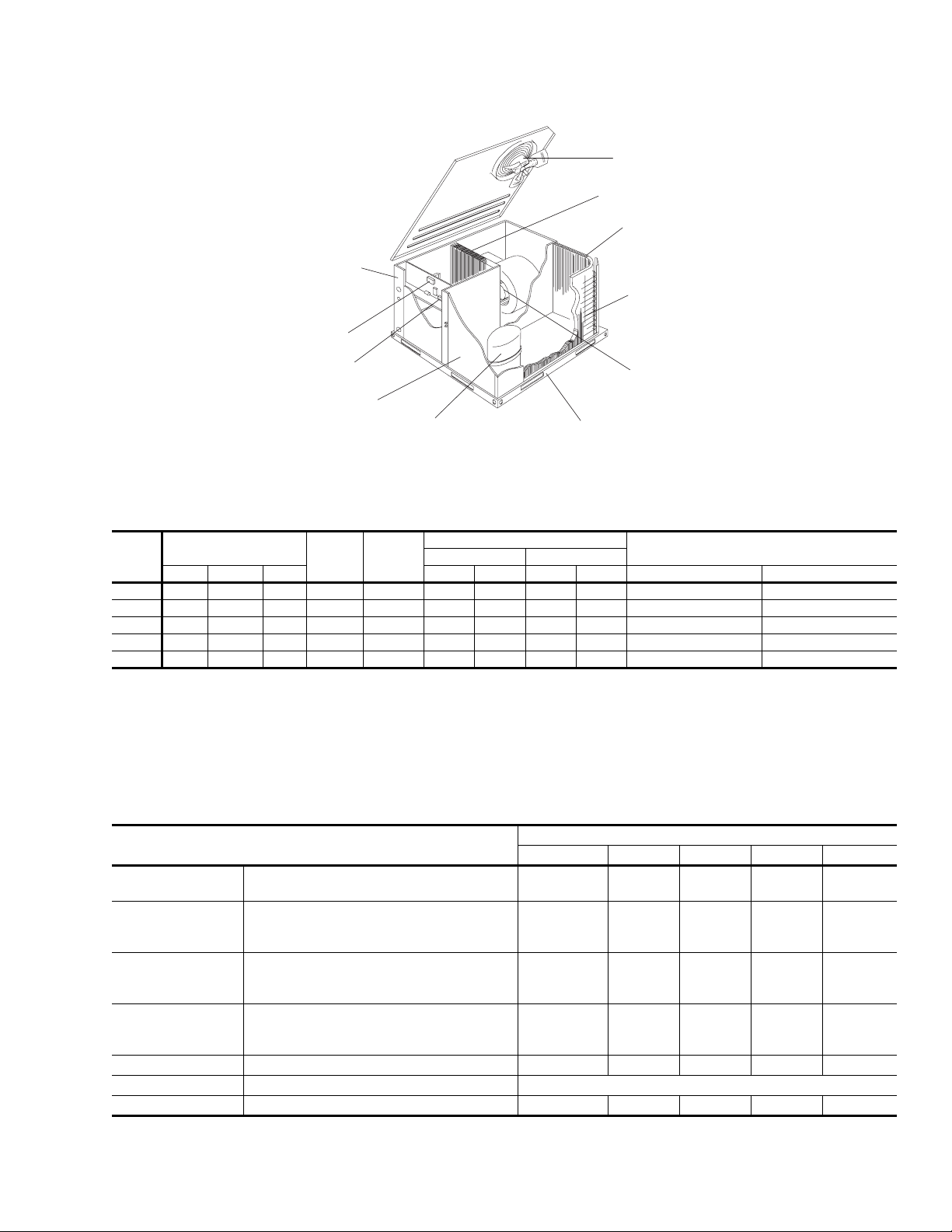
DIRECT DRIVE
CONDENSER
FAN MOTOR
HIGHLY EFFICIENT ENHANCED
COPPER TUBE/ALUMINUM FIN
INDOOR COIL
HIGHLY EFFICIENT
ENHANCED COPPER
TUBE/ALUMINUM FIN
OUTDOOR COIL
BACK AND BOTTOM
RETURN AIR
AND SUPPLYAIR
DUCT OPENING
HIGH VOLTAGE
TERMINAL BLOCK
LOW VOLTAGE
TERMINAL BLOCK
LONG-LASTING
POWDER PAINT
FINISH
HIGH-EFFICIENCY
COMPRESSOR
RIGIDLY
MOUNTED
DECORATIVE
PROTECTIVE
COIL GUARD
ECM DIRECT DRIVE
BLOWER MOTOR WITH
SLIDE-OUT BLOWER ASSEMBLY
HEAVY GAUGE
REMOVABLE
BASE RAILS
FIGURE 1 - UNIT CUT AWAY
TABLE 1: RATINGS
MODEL
BHP
COOLING CAPACITY
80 / 67-95∞F
1
HSPF
MBH SEER EER MBH COP MBH COP SINGLE PHASE THREE PHASE
1
SOUND
RATING
(dbels)
2
024 24.4 13.0 11.3 7.6 79 21.8 3.40 11.0 2.00 5.0, 7.5, 10.0 N / A
030 30.0 13.0 11.3 7.6 77 28.2 3.40 16.5 2.20 5.0, 7.5, 10.0, 15.0 10.0, 15.0
036 35.5 13.0 11.3 7.6 77 32.0 3.30 18.9 2.20 5.0, 7.5, 10.0, 15.0 10.0, 15.0
042 42.0 13.0 11.3 7.6 83 42.0 3.40 23.0 2.20 10.0, 15.0 10.0, 15.0
048 47.0 13.0 11.3 7.6 82 45.0 3.30 25.8 2.20 10.0, 15.0, 20.0, 25.0 10.0, 15.0, 20.0, 25.0
1.
Certified in accordance with the Uniary Small Equipment certification program, which is based on ARI Standard 210/240.
2.
Rated in accordance with ARI Standard 270.
SEER =Seasonal Energy Efficiency Ratio - the total cooling output in BTU's during a normal annual usage period for cooling divided by the total electric
power input in watt-hours during the same period.
COP = Coefficient of Performance - the total heating capacity provided by the refrigeration system, including circulating fan heat but excluding supplementary resistance (BGUís per hour) divided by the total electric input (watts) x 3.412.
NET HEATING CAPACITY
@47∞F@17∞F
AVAILABLE ELECTRIC HEAT
NOMINAL CAPACITY KW
TABLE 2: PHYSICAL DATA
BHP
11 x 1 0
3/4
3
15
4.38
22
1/4
2,400
2
20
11. 7
11 x 10
3/4
3
16
5.63
22
1/4
2,400
2
20
16.4
INDOOR
BLOWER
INDOOR
COIL
OUTDOOR
FAN
OUTDOOR
COIL
MODELS
CENTRIFUGAL BLOWER (Dia. x Wd. in.)
FAN MOTOR HP (ECM)
ROWS DEEP
FINS PER INCH
FACE AREA (Sq. Ft.)
PROPELLER DIA. (in.)
FAN MOTOR HP
NOM. CFM TOTAL
ROWS DEEP
FINS PER INCH
FACE AREA (Sq. Ft.)
024 030 036 042 048
10 X 8
1/2
2
15
4.38
22
1/4
1,800
1
20
11. 7
10 X 8
1/2
3
13
4.38
22
1/4
1,800
1
20
11. 7
CHARGE REFRIGERANT 22 (lbs./oz.) 5 / 5 5 / 15 8 / 4 9 / 14 12 / 0
FILTER FACE AREA (Sq. Ft. / Qty. / Size) 4.28 / 2 / 14 x 22
COMPRESSOR Hermetic Type, Qty. = 1 Reciprocating Scroll Scroll Scroll Scroll
11 X 1 0
3/4
3
16
5.63
22
1/4
3,000
2
20
16.4
Unitary Products Group 5
Page 6

TABLE 3: COOLING CAPACITIES - 2 TON (BHP024)
TEMPERATURE AIR ON
OUTDOOR COIL
72 67 62 57 72 67 62 57
NET CAP. MBH 29.1 26.0 23.8 23.4 29.7 26.6 24.3 23.9
POWER INPUT kW 1.93 1.91 1.88 1.87 1.95 1.93 1.91 1.90
86 19.2 23.1 23.8 23.4 20.9 25.1 24.3 23.9
83 16.9 20.8
85 ∞F
95 ∞F
105 ∞F
115 ∞F
125 ∞F
1.
These capacities are net capacities - indoor fan heat deducted.
1
MBH
Sensible Capacity
NET CAP. MBH 27.2 24.2 22.1 22.0 27.7 24.6 22.5 22.4
POWER INPUT kW 2.07 2.06 2.02 2.02 2.09 2.08 2.05 2.04
1
MBH
Sensible Capacity
NET CAP. MBH 23.8 22.4 20.5 20.6 24.2 22.8 20.8 20.9
POWER INPUT kW 2.20 2.21 2.17 2.16 2.24 2.24 2.20 2.19
1
MBH
Sensible Capacity
NET CAP. MBH 20.4 20.7 18.9 19.2 20.6 20.9 19.1 19.4
POWER INPUT kW 2.34 2.36 2.32 2.31 2.38 2.40 2.36 2.35
1
MBH
Sensible Capacity
NET CAP. MBH 17.0 18.9 17.3 17.8 17.0 19.0 17.5 17.9
POWER INPUT kW 2.47 2.51 2.46 2.45 2.52 2.56 2.51 2.50
1
MBH
Sensible Capacity
Entering Dry
Entering Dry
Entering Dry
Entering Dry
Entering Dry
80 14.5 18.5 21.9 22.7 15.6 19.8 23.4 23.6
77 12.2 16.1 19.5 20.3 12.9 17.2 20.7 20.9
Bulb ∞F
74 9.9 13.8 17.2 18.0 10.3 14.5 18.0 18.2
71 #N/A 11.5 14.9 15.7 #N/A 11.9 15.4 15.6
68 #N/A 9.1 12.5 13.3 #N/A 9.2 12.7 12.9
86 18.6 22.3 22.1 22.0 20.1 23.7 22.5 22.4
83 16.2 20.0
80 13.9 17.7 20.8 21.4 14.8 18.9 21.8 22.1
77 11.6 15.3 18.4 19.0 12.2 16.2 19.2 19.4
Bulb ∞F
74 9.2 13.0 16.1 16.7 9.5 13.5 16.5 16.8
71 #N/A 10.7 13.8 14.4 #N/A 10.9 13.8 14.1
68 #N/A 8.3 11.4 12.0 #N/A 8.2 11.2 11.5
86 19.5 21.5 20.5 20.6 20.4 22.3 20.8 20.9
83 17.2 19.2
80 14.9 16.9 19.7 20.0 15.9 18.1 20.4 20.6
77 12.6 14.6 17.4 17.7 13.3 15.4 17.8 18.0
Bulb ∞F
74 10.2 12.2 15.1 15.3 10.6 12.7 15.1 15.3
71 #N/A 9.9 12.7 13.0 #N/A 10.1 12.4 12.6
68 #N/A 7.6 10.4 10.7 #N/A 7.4 9.8 10.0
86 20.4 20.7 18.9 19.2 20.6 20.9 19.1 19.4
83 18.2 18.5 18.9 19.2 19.5 19.8 19.1 19.4
80 15.9 16.1 18.7 18.6 17.0 17.3 19.0 19.1
77 13.6 13.8 16.4 16.3 14.4 14.6 16.4 16.5
Bulb ∞F
74 11.2 11.5 14.1 14.0 11.7 11.9 13.7 13.8
71 #N/A 9.1 11.7 11.6 #N/A 9.3 11.1 11.2
68 #N/A 6.8 9.4 9.3 #N/A 6.6 8.4 8.5
86 21.3 19.9 17.3 17.8 20.8 19.5 17.5 17.9
83 19.2 17.7
80 16.9 15.4
77 14.6 13.0 15.4 15.0 15.4 13.8 15.0 15.0
Bulb ∞F
74 12.2 10.7 13.1 12.6 12.8 11.1 12.3 12.3
71 #N/A 8.4 10.7 10.3 #N/A 8.5 9.7 9.7
68 #N/A 6.0 8.4 8.0 #N/A 5.8 7.0 7.0
036-21528-001-A-0303
TEMPERATURE OF AIR ON INDOOR COIL
800 CFM 900 CFM
WB ∞FWB ∞F
23.8 23.4 18.3 22.5 24.3 23.9
22.1 22.0 17.5 21.5 22.5 22.4
20.5 20.6 18.5 20.7 20.8 20.9
17.3 17.8 20.6 18.9 17.5 17.9
17.7 17.3 18.1 16.5 17.6 17.7
ALL SENSIBLE CAPACITY
6 Unitary Products Group
Page 7
03 6-21528-00 1-A-0303
TABLE 4: COOLING CAPACITIES - 2-1/2 TON (BHP030)
TEMPERATURE OF AIR ON INDOOR COIL
TEMPERATURE AIR ON
OUTDOOR COIL
72 67 62 57 72 67 62 57
NET CAP. MBH 34.1 31.5 28.4 29.9 35.4 32.7 29.5 31.0
POWER INPUT kW 2.52 2.48 2.44 2.43 2.64 2.58 2.54 2.53
86 23.9 29.8 28.4 29.9 25.7 31.8 29.5 31.0
83 21.0 26.9
85 ∞F
95 ∞F
105 ∞F
115 ∞F
125 ∞F
1.
These capacities are net capacities - indoor fan heat deducted.
1
MBH
Sensible Capacity
NET CAP. MBH 32.6 29.4 26.8 28.9 33.7 30.4 27.7 29.8
POWER INPUT kW 2.83 2.81 2.71 2.70 2.93 2.91 2.81 2.79
1
MBH
Sensible Capacity
NET CAP. MBH 30.3 27.2 25.0 26.7 31.5 28.2 26.0 27.7
POWER INPUT kW 3.14 3.12 3.04 3.06 3.24 3.22 3.14 3.16
1
MBH
Sensible Capacity
NET CAP. MBH 28.0 24.9 23.2 24.4 29.3 26.1 24.4 25.6
POWER INPUT kW 3.45 3.43 3.37 3.42 3.56 3.54 3.48 3.53
1
MBH
Sensible Capacity
NET CAP. MBH 25.6 22.7 21.4 22.2 27.2 24.0 22.7 23.5
POWER INPUT kW 3.76 3.74 3.70 3.78 3.87 3.85 3.82 3.89
1
MBH
Sensible Capacity
Entering Dry
Entering Dry
Entering Dry
Entering Dry
Entering Dry
80 18.1 23.9 27.9 29.6 19.0 25.2 29.2 30.8
77 15.2 21.0 24.9 26.6 15.7 21.9 25.9 27.5
Bulb ∞F
74 12.3 18.1 22.0 23.7 12.4 18.5 22.6 24.2
71 #N/A 15.2 19.1 20.8 #N/A 15.2 19.2 20.9
68 #N/A 12.3 16.2 17.9 #N/A 11.9 15.9 17.5
86 22.8 28.2 26.8 28.9 25.0 29.7 27.7 29.8
83 19.9 25.3
80 17.0 22.4 26.6 28.3 18.3 24.2 27.5 29.5
77 14.1 19.5 23.6 25.4 15.0 20.8 24.2 26.2
Bulb ∞F
74 11.1 16.5 20.7 22.5 11.7 17.5 20.9 22.9
71 #N/A 13.6 17.8 19.6 #N/A 14.2 17.6 19.6
68 #N/A 10.7 14.9 16.7 #N/A 10.9 14.3 16.2
86 21.7 26.6 25.0 26.7 23.9 27.9 26.0 27.7
83 18.8 24.1
80 15.9 21.1 25.4 26.3 17.2 22.9 26.2 27.5
77 13.0 18.2 22.4 23.3 13.9 19.6 22.9 24.2
Bulb ∞F
74 10.1 15.3 19.5 20.4 10.6 16.3 19.6 20.9
71 #N/A 12.4 16.6 17.5 #N/A 13.0 16.2 17.6
68 #N/A 9.5 13.7 14.6 #N/A 9.7 12.9 14.2
86 20.7 24.9 23.2 24.4 22.8 26.1 24.4 25.6
83 17.7 22.8 23.2 24.4 19.5 25.0 24.4 25.6
80 14.8 19.9 24.2 24.2 16.2 21.7 24.8 25.5
77 11.9 17.0 21.3 21.3 12.8 18.4 21.5 22.2
Bulb ∞F
74 9.0 14.1 18.3 18.4 9.5 15.1 18.2 18.9
71 #N/A 11.2 15.4 15.4 #N/A 11.8 14.9 15.5
68 #N/A 8.3 12.5 12.5 #N/A 8.4 11.6 12.2
86 19.6 23.3 21.4 22.2 21.7 24.3 22.7 23.5
83 16.7 21.6
80 13.7 18.7 23.0 22.1 15.1 20.5
77 10.8 15.8 20.1 19.2 11.7 17.2 20.2 20.2
Bulb ∞F
74 7.9 12.9 17.1 16.3 8.4 13.9 16.8 16.8
71 #N/A 10.0 14.2 13.4 #N/A 10.5 13.5 13.5
68 #N/A 7.1 11.3 10.4 #N/A 7.2 10.2 10.2
1000 CFM 1125 CFM
WB ∞FWB ∞F
28.4 29.9 22.4 28.5 29.5 31.0
26.8 28.9 21.7 27.5 27.7 29.8
25.0 26.7 20.6 26.3 26.0 27.7
21.4 22.2 18.4 23.8 22.7 23.5
23.5 23.5
ALL SENSIBLE CAPACITY
Unitary Products Group 7
Page 8

TABLE 5: COOLING CAPACITIES - 3 TON (BHP036)
TEMPERATURE AIR ON
OUTDOOR COIL
72 67 62 57 72 67 62 57
NET CAP. MBH 41.137.534.534.342.438.635.535.3
POWER INPUT kW 2.89 2.81 2.73 2.73 3.00 2.91 2.83 2.82
86 25.6 32.3 34.5 34.3 28.2 35.5 35.5 35.3
83 22.5 29.3 33.5 33.6 24.7 32.0
85 ∞F
95 ∞F
105 ∞F
115 ∞F
125 ∞F
1.
These capacities are net capacities - indoor fan heat deducted.
1
MBH
Sensible Capacity
NET CAP. MBH 38.534.932.532.639.435.833.333.4
POWER INPUT kW 3.21 3.15 3.05 3.06 3.31 3.25 3.15 3.16
1
MBH
Sensible Capacity
NET CAP. MBH 35.632.129.530.436.432.830.231.1
POWER INPUT kW 3.61 3.52 3.44 3.45 3.70 3.61 3.53 3.54
1
MBH
Sensible Capacity
NET CAP. MBH 32.629.326.528.233.329.927.028.8
POWER INPUT kW 4.01 3.88 3.83 3.84 4.10 3.97 3.91 3.92
1
MBH
Sensible Capacity
NET CAP. MBH 29.726.423.526.030.226.923.926.4
POWER INPUT kW 4.41 4.25 4.21 4.22 4.49 4.33 4.29 4.30
1
MBH
Sensible Capacity
Entering Dry
Entering Dry
Entering Dry
Entering Dry
Entering Dry
80 19.5 26.3 31.7 32.2 21.2 28.5 34.5 35.0
77 16.5 23.2 28.7 29.1 17.7 25.0 31.0 31.5
Bulb ∞F
74 13.4 20.2 25.7 26.1 14.2 21.6 27.5 28.0
71 #N/A 17.2 22.6 23.1 #N/A 18.1 24.0 24.5
68 #N/A 14.1 19.6 20.0 #N/A 14.6 20.5 21.0
86 25.0 30.9 32.5 32.6 27.5 33.9 33.3 33.4
83 22.0 27.9 31.9 32.0 24.0 30.4
80 19.0 24.8 30.5 30.6 20.5 26.9 33.0 33.1
77 15.9 21.8 27.5 27.5 17.0 23.4 29.5 29.6
Bulb ∞F
74 12.9 18.8 24.4 24.5 13.5 19.9 26.0 26.1
71 #N/A 15.7 21.4 21.5 #N/A 16.4 22.5 22.6
68 #N/A 12.7 18.4 18.5 #N/A 12.9 19.0 19.1
86 23.9 29.4 29.5 30.4 26.2 31.9 30.2 31.1
83 20.9 26.6 29.2 30.0 22.7 28.9
80 17.9 23.6 27.8 28.6 19.2 25.4 30.0 30.8
77 14.8 20.5 24.8 25.5 15.7 21.9 26.5 27.3
Bulb ∞F
74 11.8 17.5 21.8 22.5 12.2 18.4 23.0 23.8
71 #N/A 14.5 18.7 19.5 #N/A 14.9 19.5 20.3
68 #N/A 11.4 15.7 16.4 #N/A 11.4 16.0 16.8
86 22.8 27.8 26.5 28.2 25.0 29.9 27.0 28.8
83 19.8 25.3 26.5 28.0 21.5 27.4 27.0 28.8
80 16.8 22.3 25.2 26.5 18.0 23.9 27.0 28.5
77 13.7 19.2 22.2 23.5 14.5 20.4 23.5 25.0
Bulb ∞F
74 10.7 16.2 19.1 20.5 11.0 16.9 20.0 21.5
71 #N/A 13.2 16.1 17.4 #N/A 13.4 16.5 18.0
68 #N/A 10.1 13.1 14.4 #N/A 9.9 13.0 14.5
86 21.7 26.3 23.5 26.0 23.7 27.9 23.9 26.4
83 18.7 24.0 23.8 25.9 20.2 25.9
80 15.7 21.0 22.6 24.5 16.7 22.4 24.1 26.2
77 12.6 17.9 19.5 21.5 13.2 18.9 20.6 22.7
Bulb ∞F
74 9.6 14.9 16.5 18.4 9.7 15.4 17.1 19.2
71 #N/A 11.9 13.5 15.4 #N/A 11.9 13.6 15.7
#78 #N/A 8.8 10.4 12.4 #N/A 8.4 10.1 12.2
1050 CFM 1200 CFM
036-21528-001-A-0303
TEMPERATURE OF AIR ON INDOOR COIL
WB ∞FWB ∞F
35.5 35.3
33.3 33.4
30.2 31.1
23.9 26.4
ALL SENSIBLE CAPACITY
8 Unitary Products Group
Page 9
03 6-21528-00 1-A-0303
TABLE 6: COOLING CAPACITIES - 3-1/2 TON (BHP042)
TEMPERATURE OF AIR ON INDOOR COIL
TEMPERATURE AIR ON
OUTDOOR COIL
72 67 62 57 72 67 62 57
NET CAP. MBH 48.8 44.5 40.5 40.6 49.2 44.9 40.8 41.0
POWER INPUT kW 3.37 3.32 3.21 3.20 3.43 3.38 3.27 3.26
86 31.6 39.4 40.5 40.6 33.0 41.0 40.8 41.0
83 27.8 35.6 40.1 40.5 28.9 36.9
85 ∞F
95 ∞F
105 ∞F
115 ∞F
125 ∞F
1.
These capacities are net capacities - indoor fan heat deducted.
1
MBH
Sensible Capacity
NET CAP. MBH 45.4 41.5 38.3 38.5 45.7 41.9 38.6 38.8
POWER INPUT kW 3.67 3.66 3.54 3.54 3.72 3.71 3.60 3.60
1
MBH
Sensible Capacity
NET CAP. MBH 41.9 37.7 35.2 35.6 42.1 37.9 35.4 35.7
POWER INPUT kW 4.01 3.98 3.89 3.88 4.06 4.03 3.94 3.93
1
MBH
Sensible Capacity
NET CAP. MBH 38.7 34.2 32.4 32.9 38.8 34.3 32.5 33.0
POWER INPUT kW 4.41 4.35 4.28 4.28 4.46 4.40 4.33 4.32
1
MBH
Sensible Capacity
NET CAP. MBH 35.6 30.7 29.6 30.3 35.5 30.6 29.6 30.2
POWER INPUT kW 4.81 4.73 4.68 4.67 4.85 4.77 4.72 4.71
1
MBH
Sensible Capacity
Entering Dry
Entering Dry
Entering Dry
Entering Dry
Entering Dry
80 24.0 31.8 38.8 40.2 24.8 32.8 40.1 41.5
77 20.2 27.9 35.0 36.4 20.7 28.8 36.0 37.4
Bulb ∞F
74 16.4 24.1 31.2 32.6 16.7 24.7 31.9 33.4
71 #N/A 20.3 27.4 28.7 #N/A 20.6 27.9 29.3
68 #N/A 16.5 23.5 24.9 #N/A 16.5 23.8 25.2
86 30.7 38.2 38.3 38.5 32.0 39.8 38.6 38.8
83 26.9 34.4 38.1 38.3 27.9 35.7
80 23.0 30.6 37.5 37.9 23.9 31.6 38.8 39.2
77 19.2 26.8 33.6 34.0 19.8 27.6 34.7 35.1
Bulb ∞F
74 15.4 23.0 29.8 30.2 15.7 23.5 30.6 31.0
71 #N/A 19.1 26.0 26.4 #N/A 19.4 26.5 26.9
68 #N/A 15.3 22.2 22.6 #N/A 15.3 22.4 22.8
86 28.1 34.5 35.2 35.6 29.4 35.8 35.4 35.7
83 24.5 31.6 34.8 35.1 25.6 33.0 35.2 35.5
80 21.0 28.1 33.7 33.8 21.8 29.1 34.9 35.1
77 17.4 24.6 30.1 30.3 18.0 25.3 31.1 31.2
Bulb ∞F
74 13.9 21.0 26.6 26.7 14.1 21.5 27.3 27.4
71 #N/A 17.5 23.0 23.2 #N/A 17.7 23.5 23.6
68 #N/A 13.9 19.5 19.6 #N/A 13.9 19.7 19.8
86 26.8 32.5 32.4 32.9 28.1 33.4 32.5 33.0
83 23.3 30.2 32.1 32.3 24.3 31.5 32.3 32.7
80 19.7 26.7 31.2 31.0 20.5 27.7 32.4 32.2
77 16.2 23.1 27.6 27.5 16.7 23.9 28.6 28.4
Bulb ∞F
74 12.6 19.6 24.1 24.0 12.9 20.1 24.8 24.6
71 #N/A 16.1 20.6 20.4 #N/A 16.3 20.9 20.8
68 #N/A 12.5 17.0 16.9 #N/A 12.5 17.1 17.0
86 25.5 30.4 29.6 30.3 26.8 31.0 29.6 30.2
83 22.0 28.8 29.4 29.6 23.0 30.1 29.5 29.9
80 18.5 25.3 28.7 28.3 19.2 26.3 29.8 29.4
77 14.9 21.7 25.1 24.8 15.4 22.5 26.0 25.6
Bulb ∞F
74 11.4 18.2 21.6 21.2 11.6 18.6 22.2 21.8
71 #N/A 14.6 18.1 17.7 #N/A 14.8 18.4 18.0
68 #N/A 11.1 14.5 14.1 #N/A 11.0 14.6 14.2
1300 CFM 1400 CFM
WB ∞FWB ∞F
40.8 41.0
38.6 38.8
ALL SENSIBLE CAPACITY
Unitary Products Group 9
Page 10

TABLE 7: COOLING CAPACITIES - 4 TON (BHP048)
TEMPERATURE AIR ON
OUTDOOR COIL
72 67 62 57 72 67 62 57
NET CAP. MBH 54.350.445.748.254.951.046.348.8
POWER INPUT kW 3.97 3.85 3.75 3.74 4.06 3.94 3.83 3.83
86 35.5 45.1 45.7 48.2 37.2 47.1 46.3 48.8
83 31.2 40.8 45.3 47.5 32.5 42.4
85 ∞F
95 ∞F
105 ∞F
115 ∞F
125 ∞F
1.
These capacities are net capacities - indoor fan heat deducted.
1
MBH
Sensible Capacity
NET CAP. MBH 52.047.443.546.152.347.743.846.4
POWER INPUT kW 4.33 4.25 4.17 4.11 4.43 4.35 4.26 4.20
1
MBH
Sensible Capacity
NET CAP. MBH 48.844.240.143.249.044.540.343.5
POWER INPUT kW 4.71 4.62 4.52 4.47 4.81 4.71 4.61 4.56
1
MBH
Sensible Capacity
NET CAP. MBH 45.941.437.040.746.141.537.140.8
POWER INPUT kW 5.19 5.08 4.96 4.93 5.28 5.17 5.05 5.02
1
MBH
Sensible Capacity
NET CAP. MBH 43.138.533.938.143.238.634.038.2
POWER INPUT kW 5.66 5.53 5.40 5.39 5.76 5.63 5.50 5.48
1
MBH
Sensible Capacity
Entering Dry
Entering Dry
Entering Dry
Entering Dry
Entering Dry
80 26.8 36.4 43.7 45.2 27.8 37.8 45.3 46.9
77 22.5 32.0 39.3 40.9 23.2 33.1 40.6 42.3
Bulb ∞F
74 18.1 27.7 35.0 36.5 18.5 28.4 36.0 37.6
71 #N/A 23.3 30.6 32.2 #N/A 23.8 31.3 32.9
68 #N/A 19.0 26.3 27.8 #N/A 19.1 26.6 28.3
86 34.6 43.5 43.5 46.1 36.1 45.3 43.8 46.4
83 30.3 39.1 43.1 45.4 31.5 40.6
80 25.9 34.8 42.1 43.2 26.8 36.0 43.6 44.7
77 21.5 30.4 37.8 38.8 22.1 31.3 38.9 40.0
Bulb ∞F
74 17.2 26.1 33.4 34.5 17.5 26.6 34.3 35.3
71 #N/A 21.7 29.1 30.1 #N/A 22.0 29.6 30.7
68 #N/A 17.3 24.7 25.8 #N/A 17.3 24.9 26.0
86 32.0 40.2 40.1 43.2 33.5 41.8 40.3 43.5
83 28.0 36.5 39.7 41.8 29.2 38.0 40.1 42.7
80 23.9 32.4 39.6 39.3 24.8 33.6 41.0 40.8
77 19.9 28.4 35.5 35.3 20.5 29.3 36.7 36.4
Bulb ∞F
74 15.9 24.3 31.5 31.2 16.1 24.9 32.3 32.0
71 #N/A 20.3 27.4 27.2 #N/A 20.6 28.0 27.7
68 #N/A 16.2 23.4 23.1 #N/A 16.2 23.6 23.3
86 31.0 38.7 37.0 40.7 32.5 40.2 37.1 40.8
83 26.9 35.3 37.0 39.3 28.1 36.8 37.1 40.1
80 22.9 31.3 38.4 36.9 23.8 32.5 39.9 38.3
77 18.8 27.2 34.4 32.9 19.4 28.1 35.6 34.0
Bulb ∞F
74 14.8 23.2 30.4 28.8 15.0 23.8 31.2 29.6
71 #N/A 19.1 26.3 24.8 #N/A 19.4 26.8 25.3
68 #N/A 15.1 22.3 20.7 #N/A 15.0 22.5 20.9
86 29.9 37.3 33.9 38.1 31.4 38.6 34.0 38.2
83 25.9 34.2 34.2 36.8 27.0 35.7 34.1 37.5
80 21.8 30.1 37.3 34.5 22.7 31.3 38.8 35.9
77 17.8 26.1 33.3 30.5 18.3 27.0 34.5 31.5
Bulb ∞F
74 13.7 22.0 29.3 26.4 14.0 22.6 30.1 27.2
71 #N/A 18.0 25.2 22.4 #N/A 18.3 25.7 22.8
68 #N/A 14.0 21.2 18.4 #N/A 13.9 21.4 18.5
1500 CFM 1600 CFM
036-21528-001-A-0303
TEMPERATURE OF AIR ON INDOOR COIL
WB ∞FWB ∞F
46.3 48.8
43.8 46.4
ALL SENSIBLE CAPACITY
10 Unitary Products Group
Page 11

03 6-21528-00 1-A-0303
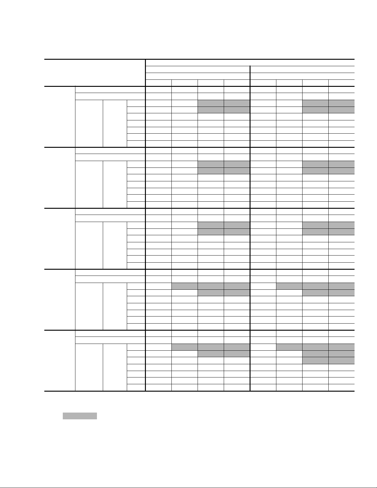
TABLE 8: HEATING CAPACITIES - 2 TON (BHP024)
CFM
600
800
1000
1.
RETURN
AIR ∞F
55
70
80
55
70
80
55
70
80
These capacities are net capacities - the indoor motor heat has been added. These power inputs are total power inputs - the indoor motor watts have
been added.
1
CAP
& KW
MBH 10.216 11.748 13.601 15.843 18.554 21.834 25.801 30.601
KW 1.214 1.307 1.401 1.494 1.588 1.681 1.775 1.868
MBH 7.317 8.849 10.702 12.944 15.655 18.935 22.902 27.702
KW 1.363 1.456 1.550 1.643 1.737 1.830 1.924 2.017
MBH 7.205 8.737 10.590 12.832 15.543 18.823 22.790 27.590
KW 1.423 1.516 1.610 1.703 1.797 1.890 1.984 2.077
MBH 10.206 11.738 13.591 15.833 18.544 21.824 25.791 30.591
KW 1.227 1.320 1.414 1.507 1.601 1.694 1.788 1.881
MBH 7.307 8.839 10.692 12.934 15.645 18.925 22.892 27.692
KW 1.376 1.469 1.563 1.656 1.750 1.843 1.937 2.030
MBH 7.195 8.727 10.580 12.822 15.533 18.813 22.780 27.580
KW 1.436 1.529 1.623 1.716 1.810 1.903 1.997 2.090
MBH 11.377 12.909 14.762 17.004 19.715 22.995 26.962 31.762
KW 1.339 1.432 1.526 1.619 1.713 1.806 1.900 1.993
MBH 8.478 10.010 11.863 14.105 16.816 20.096 24.063 28.863
KW 1.488 1.581 1.675 1.768 1.862 1.955 2.049 2.142
MBH 8.366 9.898 11.751 13.993 16.704 19.984 23.951 28.751
KW 1.548 1.641 1.735 1.828 1.922 2.015 2.109 2.202
-10 0 10 20 30 40 50 60
OUTDOOR AIR TEMPERATURE, ∞F (72% RH)
TABLE 9: HEATING CAPACITIES - 2-1/2 TON (BHP030)
CFM
750
1000
1250
RETURN
AIR ∞F
55
70
80
55
70
80
55
70
80
1.
These capacities are net capacities - the indoor motor heat has been added. These power inputs are total power inputs - the indoor motor watts have
been added.
1
CAP
& KW
MBH 10.876 12.808 15.078 17.744 20.877 24.556 28.879 33.958
KW 1.847 1.917 1.987 2.057 2.127 2.198 2.268 2.338
MBH 10.046 11.978 14.248 16.914 20.047 23.726 28.049 33.128
KW 2.135 2.205 2.275 2.345 2.415 2.486 2.556 2.626
MBH 9.054 10.986 13.256 15.922 19.055 22.734 27.057 32.136
KW 2.377 2.447 2.517 2.587 2.657 2.728 2.798 2.868
MBH 11.886 13.818 16.088 18.754 21.887 25.566 29.889 34.968
KW 1.731 1.801 1.871 1.941 2.011 2.082 2.152 2.222
MBH 11.056 12.988 15.258 17.924 21.057 24.736 29.059 34.138
KW 2.019 2.089 2.159 2.229 2.299 2.370 2.440 2.510
MBH 10.064 11.996 14.266 16.932 20.065 23.744 28.067 33.146
KW 2.261 2.331 2.401 2.471 2.541 2.612 2.682 2.752
MBH 13.978 15.910 18.180 20.846 23.979 27.658 31.981 37.060
KW 1.881 1.951 2.021 2.091 2.161 2.232 2.302 2.372
MBH 13.148 15.080 17.350 20.016 23.149 26.828 31.151 36.230
KW 2.169 2.239 2.309 2.379 2.449 2.520 2.590 2.660
MBH 12.156 14.088 16.358 19.024 22.157 25.836 30.159 35.238
KW 2.411 2.481 2.551 2.621 2.691 2.762 2.832 2.902
-10 0 10 20 30 40 50 60
OUTDOOR AIR TEMPERATURE, ∞F (72% RH)
Unitary Products Group 11
Page 12

036-21528-001-A-0303
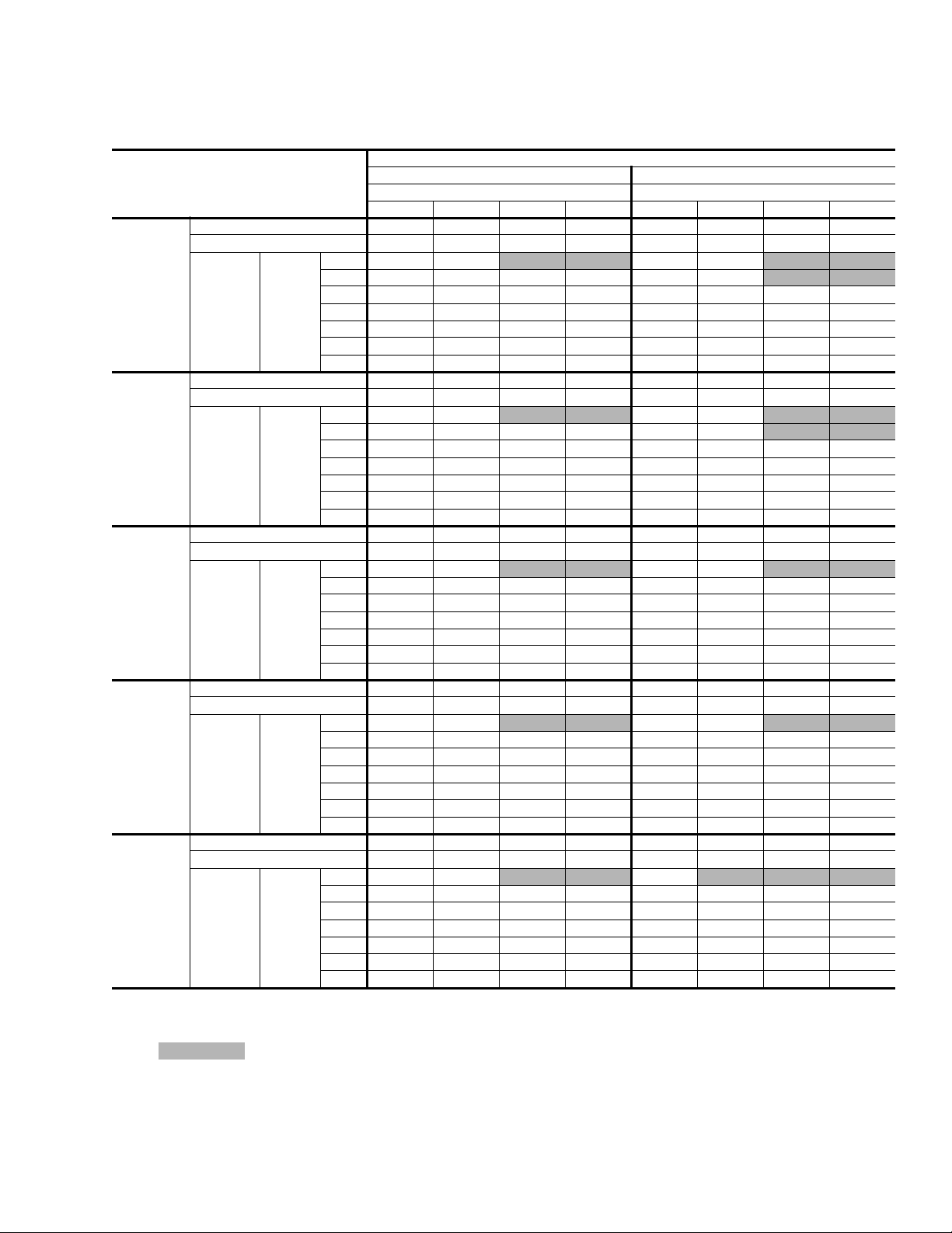
TABLE 10: HEATING CAPACITIES - 3 TON (BHP036)
CFM
900
1200
1500
RETURN
AIR ∞F
55
70
80
55
70
80
55
70
80
1.
These capacities are net capacities - the indoor motor heat has been added. These power inputs are total power inputs - the indoor motor watts have
been added.
1
CAP
& KW
MBH 10.597 12.792 15.448 18.660 22.545 27.244 32.929 39.804
KW 1.791 1.898 2.005 2.112 2.219 2.326 2.433 2.540
MBH 9.420 11.615 14.271 17.483 21.368 26.067 31.752 38.627
KW 2.198 2.305 2.412 2.519 2.626 2.733 2.840 2.947
MBH 7.543 9.738 12.394 15.606 19.491 24.190 29.875 36.750
KW 2.476 2.583 2.690 2.797 2.904 3.011 3.118 3.225
MBH 11.652 13.847 16.503 19.715 23.600 28.299 33.984 40.859
KW 1.825 1.932 2.039 2.146 2.253 2.360 2.467 2.574
MBH 10.475 12.670 15.326 18.538 22.423 27.122 32.807 39.682
KW 2.232 2.339 2.446 2.553 2.660 2.767 2.874 2.981
MBH 8.598 10.793 13.449 16.661 20.546 25.245 30.930 37.805
KW 2.510 2.617 2.724 2.831 2.938 3.045 3.152 3.259
MBH 12.282 14.477 17.133 20.345 24.230 28.929 34.614 41.489
KW 1.779 1.886 1.993 2.100 2.207 2.314 2.421 2.528
MBH 11.105 13.300 15.956 19.168 23.053 27.752 33.437 40.312
KW 2.186 2.293 2.400 2.507 2.614 2.721 2.828 2.935
MBH 9.228 11.423 14.079 17.291 21.176 25.875 31.560 38.435
KW 2.464 2.571 2.678 2.785 2.892 2.999 3.106 3.213
-10 0 10 20 30 40 50 60
OUTDOOR AIR TEMPERATURE, ∞F (72% RH)
TABLE 11: HEATING CAPACITIES - 3-1/2 TON (BHP042)
CFM
1050
1400
1750
RETURN
AIR ∞F
55
70
80
55
70
80
55
70
80
1.
These capacities are net capacities - the indoor motor heat has been added. These power inputs are total power inputs - the indoor motor watts have
been added.
1
CAP
& KW
MBH 15.404 17.988 20.968 24.404 28.369 32.941 38.215 44.298
KW 2.410 2.505 2.599 2.694 2.789 2.883 2.978 3.073
MBH 14.342 16.926 19.906 23.342 27.307 31.879 37.153 43.236
KW 2.835 2.930 3.024 3.119 3.214 3.308 3.403 3.498
MBH 13.669 16.253 19.233 22.669 26.634 31.206 36.480 42.563
KW 3.143 3.238 3.332 3.427 3.522 3.616 3.711 3.806
MBH 17.901 20.485 23.465 26.901 30.866 35.438 40.712 46.795
KW 2.419 2.514 2.608 2.703 2.798 2.892 2.987 3.082
MBH 16.839 19.423 22.403 25.839 29.804 34.376 39.650 45.733
KW 2.844 2.939 3.033 3.128 3.223 3.317 3.412 3.507
MBH 16.166 18.750 21.730 25.166 29.131 33.703 38.977 45.060
KW 3.152 3.247 3.341 3.436 3.531 3.625 3.720 3.815
MBH 18.901 21.485 24.465 27.901 31.866 36.438 41.712 47.795
KW 2.463 2.558 2.652 2.747 2.842 2.936 3.031 3.126
MBH 17.839 20.423 23.403 26.839 30.804 35.376 40.650 46.733
KW 2.888 2.983 3.077 3.172 3.267 3.361 3.456 3.551
MBH 17.166 19.750 22.730 26.166 30.131 34.703 39.977 46.060
KW 3.196 3.291 3.385 3.480 3.575 3.669 3.764 3.859
-10 0 10 20 30 40 50 60
OUTDOOR AIR TEMPERATURE, ∞F (72% RH)
12 Unitary Products Group
Page 13

03 6-21528-00 1-A-0303
TABLE 12: HEATING CAPACITIES - 4 TON (BHP048)
CFM
1200
1600
2000
RETURN
AIR ∞F
55
70
80
55
70
80
55
70
80
1.
These capacities are net capacities - the indoor motor heat has been added. These power inputs are total power inputs - the indoor motor watts have
been added.
1
CAP
& KW
MBH 13.911 17.096 21.021 25.859 31.821 39.170 48.226 59.388
KW 2.342 2.568 2.795 3.022 3.249 3.476 3.703 3.930
MBH 11.264 14.449 18.374 23.212 29.174 36.523 45.579 56.741
KW 2.726 2.952 3.179 3.406 3.633 3.860 4.087 4.314
MBH 9.676 12.861 16.786 21.624 27.586 34.935 43.991 55.153
KW 3.067 3.293 3.520 3.747 3.974 4.201 4.428 4.655
MBH 16.349 19.534 23.459 28.297 34.259 41.608 50.664 61.826
KW 2.408 2.634 2.861 3.088 3.315 3.542 3.769 3.996
MBH 13.702 16.887 20.812 25.650 31.612 38.961 48.017 59.179
KW 2.792 3.018 3.245 3.472 3.699 3.926 4.153 4.380
MBH 12.114 15.299 19.224 24.062 30.024 37.373 46.429 57.591
KW 3.133 3.359 3.586 3.813 4.040 4.267 4.494 4.721
MBH 17.629 20.814 24.739 29.577 35.539 42.888 51.944 63.106
KW 2.502 2.728 2.955 3.182 3.409 3.636 3.863 4.090
MBH 14.982 18.167 22.092 26.930 32.892 40.241 49.297 60.459
KW 2.886 3.112 3.339 3.566 3.793 4.020 4.247 4.474
MBH 13.394 16.579 20.504 25.342 31.304 38.653 47.709 58.871
KW 3.227 3.453 3.680 3.907 4.134 4.361 4.588 4.815
-10 0 10 20 30 40 50 60
OUTDOOR AIR TEMPERATURE, ∞F (72% RH)
Unitary Products Group 13
Page 14

036-21528-001-A-0303
TABLE 13: SIDE & BOTTOM SUPPLY AIR BLOWER PERFORMANCE (208/230/460 VOLT1)
MODEL NO.
BHP
B1HP024 Cooling TB2-A, Heating TB2-A, Electric Heat 800 CFM 91 125 161 206 240
B1HP024 Cooling TB2-B, Heating TB2-B 900 CFM 118 148 199 243 285
B1HP030 Cooling TB2-A, Heating TB2-A, Electric Heat 1000 CFM 280 321 389 449 500
B1HP030 Cooling TB2-B, Heating TB2-B 1125 CFM 356 413 490 557 620
B1HP036 Cooling TB2-A, Heating TB2-A 1050 CFM 209 261 319 372 438
B1HP036 Cooling TB2-B, Heating TB2-B, Electric Heat 1200 CFM 273 324 392 480 541
B1HP042 Electric Heat 1225 CFM 306 341 412 494 577
B1HP042 Cooling TB2-A 1300 CFM 338 395 470 551 640
B1HP042 Cooling TB2-B 1400 CFM 393 466 544 642 734
B1HP042 Heating TB2-A, TB2-B 1500 CFM 500 554 665 752 835
B1HP048 Heating TB2-A 1400 CFM 377 427 504 597 683
B1HP048 Cooling TB2-A 1500 CFM 455 516 601 703 788
B1HP048 Cooling TB2-B, Heating TB2-B, Electric Heat 1600 CFM 530 608 707 800 873
1.
All units are factory set to TB2-A.
NOTE: Above data includes allowances for a dry indoor coil and no filters. For additional pressure drops, refer to the ì Additional Static Pressure
Resistanceî table.
MOTOR SPEED
SETTING
UNIT
AIRFLOW
EXTERNAL STATIC PRESSURE - IWG
0.15 0.30 0.50 0.70 0.90
WATTS
TABLE 14: ADDITIONAL STATIC RESISTANCE
RESISTANCE, IWG
DESCRIPTION
500 600 700 800 900 1,000 1,100 1,200 1,300 1,400 1,500 1,600 1,700 1,800 1,900 2,000
Wet Indoor Coil 0.01 0.01 0.01 0.02 0.01 0.02 0.03 0.04 0.04 0.03 0.04 0.04 0.05 0.05 0.06 0.07
Economizer 0.00 0.00 0.00 0.01 0.01 0.01 0.01 0.02 0.03 0.04 0.05 0.06 0.07 0.07 0.08 0.08
Filter/Frame Kit 0.01 0.02 0.02 0.02 0.02 0.02 0.03 0.03 0.03 0.03 0.04 0.05 0.05 0.06 0.06 0.07
Electric Heat 0.02 0.03 0.03 0.03 0.04 0.04 0.05 0.06 0.07 0.08 0.09 0.10 0.01 0.11 0.11 0.12
CFM
14 Unitary Products Group
Page 15

03 6-21528-00 1-A-0303
THERMOSTAT UNIT TERMINAL STRIP
** = Minimum wire size of 18 AWG
wire should be used for all field
installed 24 volt wire.
R
G
**
R
G
YY
NOTE:
HEAT ANTICIPATOR
SHOULD BE SET AT 0.25
AMPS FOR ALL MODELS
PROGRAMMABLE
THERMOSTAT ONLY
* = Only required on units with
supplemental electric heat.
CAUTION:
Label all wires prior to disconnection when servicing controls. Wiring errors can
cause improper and dangerous operation. Verify proper operation after servicing.
W
O O
C
*
W2
W1
C
24 VOLT TRANSFORMER
FIGURE 2 - FIELD WIRING DIAGRAM
Unitary Products Group 15
Page 16

036-21528-001-A-0303
TABLE 15: ELECTRICAL DATA (BASIC UNIT)
2
MAX.
HACR
BREAKER
SIZE,
AMPS
UNIT
POWER
FACTOR
VO LTAG E
MODEL
BHP
024 208/230-1-60 187 253 9.3 57.0 1.1 5.0 17.7 25 25 0.96 40
030
036
042
048
POWER
SUPPLY
208/230-1-60 187 253 15.0 72.5 1.1 5.0 24.9 35 35 0.96 40
208/230-3-60 187 253 10.0 63.0 1.1 5.0 18.6 25 25 0.96 75
460-3-60 414 504 5.0 31.0 0.6 5.0 11.9 15 15 0.96 75
208/230-1-60 187 253 17.2 94.0 1.1 7.3 29.9 45 45 0.96 40
208/230-3-60 187 253 11.4 78.0 1.1 7.3 22.7 30 30 0.96 75
460-3-60 414 504 5.7 40.0 0.6 7.3 15.4 20 20 0.96 75
208/230-1-60 187 253 20.0 104.0 1.1 7.3 33.4 50 50 0.96 40
208/230-3-60 187 253 13.9 88.0 1.1 7.3 25.8 35 35 0.96 75
460-3-60 414 504 6.4 44.0 0.6 7.3 16.1 20 20 0.96 75
208/230-1-60 187 253 23.4 126.0 1.5 7.3 38.1 60 60 0.96 40
208/230-3-60 187 253 13.0 93.0 1.5 7.3 25.1 35 35 0.96 75
460-3-60 414 504 6.4 46.5 0.8 7.3 16.3 20 20 0.96 75
1.
Rated in accordance with ARI Standard 100, utilization range ìAî .
2.
Dual element, time delay type.
LIMITATIONS
MIN. MAX. RLA LRA
COMPRESSOR
1
OUTDOOR
FAN
MOTOR,
FLA
SUPPLY AIR
BLOWER
MOTOR,
FLA
MINIMUM
CIRCUIT
AMPACITY
MAX
FUSE
SIZE,
AMPS
TRANSFORMER
SIZE (VA)
ELECTRIC HEAT
CORRECTION
FAC TORS
NOMINAL VOLTAGE VOLTAGE KW CAP. MULTIPLIER
240
208
230
0.75
0.92
480 460 0.92
16 Unitary Products Group
Page 17

03 6-21528-00 1-A-0303
TABLE 16: ELECTRICAL DATA (13 SEER HEAT PUMP / ELECTRIC HEAT)
COMPRESSOR
POWER
SUPPLY
BHP
MODEL
024 208/230-1-60 9.3 57.0 1.1 5.0
030 208/230-1-60 15.0 72.5 1.1 5.0
036 208/230-1-60 17.2 94.0 1.1 7.3
042 208/230-1-60 20.0 104.0 1.1 7.3
048 208/230-1-60 23.4 126.0 1.5 7.3
030 208/230-3-60 10.0 63.0 1.1 5.0
036 208/230-3-60 11.4 78.0 1.1 7.3
042 208/230-3-60 13.9 88.0 1.1 7.3
048 208/230-3-60 13.0 93.0 1.5 7.3
030 460-3-60 5.0 31.0 0.6 5.0
036 460-3-60 5.7 40.0 0.6 7.3
042 460-3-60 6.4 44.0 0.6 7.3
048 460-3-60 6.4 46.5 0.8 7.3
1.
Dual element, time delay type.
2.
Standard circuit breakers may be used in Canada and on applications over 60 amps where the heaters are separately fused.
* KW listed is for 240 volts, use Table 15 for 208 or 230 volts.
** KW listed is for 480 volts, use Table 15 for 460 volts.
RLA LRA
COND
FAN
MOTOR
FLA
SUPPLY
AIR
BLOWER
MOTOR
FLA
ELECTRIC HEAT ACCESSORY
MINIMUM
MODEL NO. KW
2NH04500506 3.8 / 5.0 * 18.1 / 20.8 40.3 / 43.8 45 / 45 45 / 45
2NH04500706 5.6 / 7.5 * 27.1 / 31.3 51.6 / 56.8 60 / 60 60 / 60
2NH04501006 7.5 / 10.0 * 36.1 / 41.7 62.9 / 69.8 70 / 70 70 / 70
2NH04500506 3.8 / 5.0 * 18.1 / 20.8 47.4 / 50.9 50 / 60 50 / 60
2NH04500706 5.6 / 7.5 * 27.3 / 31.3 58.7 / 63.9 60 / 70 60 / 70
2NH04501006 7.5 / 10.0 * 36.1 / 41.7 70.0 / 76.9 70 / 80 70 / 80
2NH04501506 11.3 / 15.0 * 54.2 / 62.5 92.6 / 103.0 100 / 110 100 / 110
2NH04500506 3.8 / 5.0 * 18.1 / 20.8 52.5 / 55.9 60 / 60 60 / 60
2NH04500706 5.6 / 7.5 * 27.1 / 31.3 63.8 / 69.0 70 / 70 70 / 70
2NH04501006 7.5 / 10.0 * 36.1 / 41.7 75.0 / 82.0 80 / 90 80 / 90
2NH04501506 11.3 / 15.0 * 54.2 / 62.5 97.6 / 108.0 100 / 110 100 / 110
2NP04501006 7.5 / 10.0 * 36.1 / 41.7 78.5 / 85.5 80 / 90 80 / 90
2NP04501506 11.3 / 15.0 * 54.2 / 62.5 101.1 / 111.5 110 / 125 110 / 125
2NP04501006 7.5 / 10.0 * 36.1 / 41.7 83.2 / 90.1 90 / 100 90 / 100
2NP04501506 11.3 / 15.0 * 54.2 / 62.5 105.8 / 116.2 110 / 125 110 / 125
2NP04502006 15.0 / 20.0 * 72.2 / 83.3 128.3 / 142.2 150 / 150 150 / 150
2NP04502506 18.8 / 25.0 * 90.3 / 104.2 150.9 / 168.3 175 / 175 175 / 175
2NH04501025 7.5 / 10.0 * 20.8 / 24.1 44.7 / 48.7 45 / 50 45 / 50
2NH04501525 11.3 / 15.0 * 31.3 / 36.1 57.7 / 63.7 60 / 70 60 / 70
2NH04501025 7.5 / 10.0 * 20.8 / 24.1 48.7 / 52.7 50 / 60 50 / 60
2NH04501525 11.3 / 15.0 * 31.3 / 36.1 61.7 / 67.8 70 / 70 70 / 70
2NP04501025 7.5 / 10.0 * 20.8 / 24.1 51.8 / 55.8 60 / 60 60 / 60
2NP04501525 11.3 / 15.0 * 31.3 / 36.1 64.9 / 70.9 70 / 80 70 / 80
2NP04501025 7.5 / 10.0 * 20.8 / 24.1 51.1 / 55.1 60 / 60 60 / 60
2NP04501525 11.3 / 15.0 * 31.3 / 36.1 64.1 / 70.2 70 / 80 70 / 80
2NP04502025 15.0 / 20.0 * 41.7 / 48.1 77.2 / 85.2 80 / 90 80 / 90
2NP04502525 18.8 / 25.0 * 52.1 / 60.1 90.2 / 100.2 100 / 110 100 / 110
2NH04501046 10.0 ** 12.0 27.5 30 30
2NH04501546 15.0 ** 18.0 35.4 40 40
2NH04501046 10.0 ** 12.0 30.7 35 35
2NH04501546 15.0 ** 18.0 38.6 40 40
2NP04501046 10.0 ** 12.0 31.6 35 35
2NP04501546 15.0 ** 18.0 39.4 40 40
2NP04501046 10.0 ** 12.0 31.8 35 35
2NP04501546 15.0 ** 18.0 39.6 40 40
2NP04502046 20.0 ** 24.1 47.5 50 50
2NP04502546 25.0 ** 30.1 55.3 60 60
TOTAL
AMPS
CIRCUIT
AMPACITY
MAX.
FUSE/
SIZE,
AMPS
1
BREAKER
MAX
HACR
SIZE
2
Unitary Products Group 17
Page 18

TABLE 17: APPLICATION DATA
,
036-21528-001-A-0303
MODEL
MINIMUM AIR FLOW
(CFM)
MAXIMUM AIR FLOW
(CFM)
MINIMUM OPERATING TEMPERATURE IN COOLING MODE
MIMINIM MIXED AIR IN COOLING MODE
MINIMUM MIXED AIR IN HEATING MODE
FRONT
OF
UNIT
49
&
A
26
(AMBIENT, ∞F)
(RETURN AIR, DB ∞F/WB ∞F)
(RETURN AIR, ∞F)
CENTER OF GRAVITY
D
C
B
23
BHP
024 030 036 042 048
COOLING 800 1000 1050 1300 1500
HEATING 800 1000 1050 1400 1400
COOLING 900 1125 1200 1400 1600
HEATING 900 1125 1200 1500 1600
45 45 45 45 45
68 / 57 68 / 57 68 / 57 68 / 57 68 / 57
55 55 55 55 55
B1HP
SHIPPING
UNIT
SIZE
!
47
"
WEIGHT
024 356 351 97 93 81 84
030 353 348 96 93 81 84
036 388 383 106 102 89 92
042 440 435 120 115 101 104
048 485 480 132 127 111 115
OPERATING
WEIGHT
CORNER WEIGHTS
ABC D
FIGURE 3 - CENTER OF GRAVITY AND WEIGHTS
CLEARANCES
UNIT CLEARANCES
(MINIMUM)
Front 12î
Back 0î
Left Side (Filter Access) 24î
Right Side 24î
Below Unit
Above Unit
1.
Units may be installed on combustible floors made from
wood or class A, B or C roof covering.
2.
Units must be installed outdoors. Overhanging structures
or shrubs should not obstruct outdoor air discharge outlet.
NOTE: FOR UNITS APPLIED WITH A ROOF CURB, THE
MINIMUM CLE ARANCE MAY BE REDUCED FROM 1
INCH TO 1/2 INCH BETWEEN COMBUSTIBLE ROOF
CURB MATERIAL AND THE SUPPLY DUCT.
1
2
36î (For Condenser
0î
Air Discharge)
FIGURE 4 - UNIT CLEARANCES
MINIMUMCLEARANCEOF1"
ALLSIDESFORTHEFIRST3'
OFDUCTFOR20&25kW.
ZEROINCHESTHEREAFTER
FORALLOTHERHEATERS,
ZEROINCHCLEARANCEALL
SIDESFORENTIRE LENGTH
OFDUCT.
3'
FLEXIBLEDUCT
COLLAR
18 Unitary Products Group
Page 19

03 6-21528-00 1-A-0303
FIGURE 5 - UNIT DIMENSIONS
Unitary Products Group 19
Page 20

036-21528-001-A-0303
FIGURE 6 - TYPICAL APPLICATIONS
20 Unitary Products Group
Page 21

03 6-21528-00 1-A-0303
FIGURE 7 - ROOF CURB DIMENSIONS
Unitary Products Group 21
Page 22

036-21528-001-A-0303
FIGURE 8 - TYPICAL WIRING DIAGRAM (208/230-1-60 POWER SUPPLY)
22 Unitary Products Group
Page 23

03 6-21528-00 1-A-0303
FIGURE 9 - TYPICAL WIRING DIAGRAM (230-3-60 POWER SUPPLY)
Unitary Products Group 23
Page 24

036-21528-001-A-0303
FIGURE 10 - TYPICAL WIRING DIAGRAM (460-3-60 POWER SUPPLY)
24 Unitary Products Group
Page 25

03 6-21528-00 1-A-0303
MECHANICAL SPECIFICATIONS
GENERAL DESCRIPTION
Units shall be factory-assembled, single packaged,
Heat Pumps, designed for outdoor mounted installation. Units shall have minimum SEER ratings of 13.0.
They shall have built in, equal size, field convertible
duct connections for down discharge supply/return or
horizontal discharge supply/return.
The units shall be factory wired, piped, charged with R22 refrigerant and factory tested prior to shipment. All
unit wiring shall be both numbered and color coded.
All units shall be manufactured in a facility certified to
ISO 9001 standards, and the cooling performance shall
be rated in accordance with DOE and ARI test procedures. Units shall be classified to UL 1995/CAN/CSA
No. 236-M90 conditions.
UNIT CABINET
1. Unit cabinet shall be constructed of G90 galvanized steel, with exterior surfaces coated with a
non-chalking, powered paint finish, certified at 750
hours salt spray test per ASTM-B117 standards.
2. The unit top shall be a single piece ìWater Shedî
design, with drip edges and no-seam corners to
provide optimum water integrity.
3. Unit shall have a rigidly mounted condenser coil
guard to provide protection from objects and personnel after installation.
4. Indoor blower section shall be insulated with up to
3/4î thick, aluminum, foil faced insulation, fastened
to prevent insulation from entering the air stream.
5. Cabinet panels shall be ìlargeî size, easily removable for servicing and maintenance, with built-in lift
handles.
6. Unit shall be built on a formed, ìSuper-Structureî
design base pan, with embossments at critical
points to add strength, rigidity and aid in minimizing
sound.
7. Full perimeter base rails shall be provided to
assure reliable transit of equipment, overhead rigging, fork truck access and proper sealing on roof
curb applications. Base rails shall be removable,
when required, to lower unit height.
8. Filters shall be furnished and be accessible
through a removable access door, sealed air tight.
(Single phase models - accessory kit available.
Three phase models - standard from factory.)
9. Units vertical discharge and return duct configuration shall be designed to fit between standard 24î
O.C. beams without modification to building structure, duct work and base unit.
10. Condensate pan shall be internally sloped and
conform to ASHARE 62-89 self-draining standards,
with " NPTI copper, ridged mount connection.
INDOOR (SUPPLY) FAN ASSEMBLY
1. Fan shall be direct drive, constant CFM, ECM
design. Job site selected (BHP) brake horse power
shall not exceed the motors nameplate horse
power rating.
2. Fan wheel shall be double-inlet type with forwardcurved blades, dynamically balanced to operate
smoothly throughout the entire range of operation.
Airflow design shall be constant air volume.
3. Bearings shall be sealed and permanently lubricated for longer life and no maintenance.
4. Fan assembly shall be ìSlip Trackî (slide-out)
design for easy removal and cleaning.
OUTDOOR FAN ASSEMBLY
1. The outdoor fan shall be of the direct-driven propeller type, discharge air vertically, have aluminum
blades riveted to corrosion resistant steel spider
bracket and shall be statically balanced for smooth
operation.
2. The outdoor fan motor shall be totally enclosed
with permanently lubricated bearings and internally
protected against overload conditions.
REFRIGERANT COMPONENTS
1. Compressors:
A. Shall be fully hermetic type, direct drive, internally
protected with internal high-pressure relief and over
temperature protection. The hermetic motor shall be
suction gas cooled and have a voltage range of + or
- 10% of the unit nameplate voltage.
Unitary Products Group 25
Page 26

036-21528-001-A-0303
B. Shall have internal isolation and sound muffling to
minimize vibration and noise, and be externally isolated on a dedicated, independent mounting.
2. Coils:
A. Evaporator and condenser coils shall have alumi-
num plate fins mechanically bonded to seamless
internally-enhanced copper tubes with all joints
brazed.
B. Evaporator and Condenser coils shall be of the
direct expansion, draw-thru design.
3. Refrigerant Circuit and Refrigerant Safety Components shall include:
A. Independent thermal expansion devices (TXV).
B. Solid-core filter dryer to eliminate any foreign matter.
C. Accessible service gage connections on both suc-
tion and discharge lines to charge, evacuate, and
measure refrigerant pressure during any necessary
servicing or troubleshooting, without losing charge
and without disrupting condenser or evaporator air
flow.
D. The refrigeration system shall provide at least 10∞ F
of liquid sub-cooling at design conditions.
E. Unit shall have a suction line accumulator and auto-
matic reversing valve.
room thermostat ìLEDî indication of unit lockout.
Plus a built in 5 minute anti-short cycle protection.
D. Unit shall have large, easily removable panels, cov-
ering electrical controls and compressor, allowing
easy access for any maintenance or servicing.
ELECTRIC HEATING SECTION
1. An electric heating section, with nickel chromium
elements, shall be provided in a range of 5 thru 25
KW.
2. The heating section shall have an automatic reset
primary limit control to prevent the heating element
system from operating at an excessive temperature.
3. The heating section assembly shall slide out of the
unit for easy maintenance and service.
4. Units with electric heating sections shall be wired
for a single point power supply, with branch circuit
fusing (where required).
UNIT OPERATING CHARACTERISTICS
1. Unit shall be capable of starting and running at
125∞ F outdoor temperature, exceeding maximum
load criteria of ARI Standard 210/240.
4. Unit Controls:
A. Unit shall contain a large, low voltage Terminal
Board for easy connection of field low voltage wiring.
B. Controls shall be mounted in a large control box with
tilt-out, hinged access door, allowing easy access
for trouble shooting and maintenance without affecting the normal system operation pressures.
C. Unit shall contain a reliable demand defrost control
to provide defrost. The defrost control shall also
have an ìXî terminal to provide a 24 volt signal for
2. The compressor, with standard controls, shall be
capable of operation down to 45∞ F outdoor tem-
perature. Accessory low ambient kit shall be available for operation to 0∞ F.
ELECTRICAL REQUIREMENTS
All unit power wiring shall enter unit cabinet at a single
factory provided location and be capable of side or bottom entry. This will minimize roof penetrations and
avoid unit field modifications. Separate side and bottom openings shall be provided for the control wiring.
26 Unitary Products Group
Page 27

03 6-21528-00 1-A-0303
Unitary Products Group 27
Page 28

This product was manufactured
in a plant whose quality system
is certified/registered as being
in conformity with ISO 9001.
Subject to change without notice. Printed in U.S.A. CD: 6-21528 036-21528-001-A-0303
Copyright © by Unitary Products Group 2003. All rights reserved. Supersedes: Nothing
Unitary 5005 Norman
Products York OK
Group Drive 73069
 Loading...