

York B1HA024A25, B1HA018A25, B1HA024A46, B1HA024A58, B1HA030A06 Installation Instruction
...Page 1

CAUTION
THE ENCLOSED INSTAL L ATI ON INSTRUCT IONS AND ANY APPL ICABLE
LOCAL, STAT E , AND NATIONAL CODES INCL UDING, BUT NOT LIMITED
TO, BUILDING, ELECTRICAL, AND MECHANICAL CODES.
THIS PRODUCT MUST BE INSTALLED IN STRICT COMPLIANCE WITH
WARNING
OPERATION OF THE PRODUCT COULD CAUSE PERSONAL INJURY
OR PROPERTY DAM AGE.
I NCORRECT INSTALLATION MAY CREATE A CONDITION WHERE THE
CHAMPION® SERIES
SINGLE PACKAGE HEAT PUMPS
INSTALLATION INSTRUCTION
GENERAL
Supersedes: 035-16004-000 (0801)
MODELS B1HA018 THRU 060
1.5 THRU 5 TON
(10 SEER)
REFERENCE
035-16004-001-A-0202
YORK Model B1HAunitsarefactoryassembledheatpump s
designed for outdoor installation on a rooftop or a slab. Fieldinstalled electric heater accessories are available to provide
supplemental electric heat combined with electric cooling and
heating.
The units are completely assembled on rigid, removable
base rails. All piping, refrigerant charge, and electrical wiring
is factory installed and tested. The units require only electric
power and duct connections at the point of installation.
The electric heaters have nickel-chrome resistance wire ele
ments and utilize single point power connection.
INSPECTION
As soon as a unit is received, it should be inspected for pos
sible damage during transit. If damage is evident, the extent
of the damage should be noted on the carrier's freight bill. A
separate request for inspection by the carrier's agent should
be made in writing. Refer to Form 50.15-NM for additional in
formation.
Installer should pay particular attention to the words: NOTE, CAUTION and WARNING. Notes are intended to clarify or
make the installation easier.Cautions
sonal injury and/or equipment damage may result if installation procedure is not handled properly.
are given to prevent equipment damage. Warnings are given to alert installer that per
Additional information on the design, installation, operation
andserviceofthis equipmentis availablein thefollowing reference forms:
• 55.70-N1 -General Installation
• 55.70-N2 -Pre-start & Post-start Check List
• 511.26-N1.1V -Electric Heater Accessory
RENEWAL PARTS
•
Referto ReplacementPartsManual forcomplete listingof
-
-
-
replacement parts on this equipment.
All forms referenced in this instruction may be ordered from:
Standard Register
2101 West Techumseh Road
Norman, OK 73069
Toll Free: Tel. 877-318-9675/Fax. 877-379-7920
-
Page 2

035-16004-001-A-0202
PRODUCT NOMENCLATURE
B 1 H A A
PRODUCT CATEGORY
B = Single Package Heat Pumps
(Air Cooled)
20 4 0 6
VOLTAGE CODE
06 = 208/230-1-60
25 = 208/230-3-60
46 = 460-3-60
PRODUCT GENERATION
1 = NEW or Current Design
PRODUCT IDENTIFIER
HA = Heat Pump (10 SEER)
NOMINAL COOLING
CAPACITY(MBH)
018 = 18,000 BTUH 042 = 42,000 BTUH
024 = 24,000 BTUH 048 = 48,000 BTUH
030 = 30,000 BTUH 060 = 60,000 BTUH
036 = 36,000 BTUH
INSTALLED ELECTRIC HEAT
A = No Electric Heat Installed
58 = 575-3-60
FACTORY
INSTALLATION
LIMITATIONS
These units must be installed in accordance with the follow
ing national and local safety codes.
1. National Electrical Code ANSI/NFPS No. 70 or Canadian
Electrical Code Part 1, C22.1 (latest editions).
2. Local plumbing and waste water codes and other applica
ble local codes.
Refer to Table 1 for unit application data and to Table 4 for
electric heat application data.
If components are to be added to a unit to meet local codes,
they are to be installed at the dealer's and/or the customer's expense.
Size of unit for proposed installation should be based on
heat loss/heat gain calculations made in accordance with industry recognized procedures identified by the Air Condition
ing Contractors of America.
TABLE 1 - UNIT APPLICATION DATA
2
/ Max.
208/230V
Voltage Variation
Min. / Max
Wet Bulb Temperature (°F) of Air on
Evaporator Coil, Min. / Max.
Dry Bulb Temperature (°F) of Air on
Condenser Coil, Min.
1
Rated in accordance with ARI Standard 110, utilization range “A”.
2
A low ambient accessory is available for operation down to 0°F
3
“T1" transformer primary tap must be moved from the 230 volt connection to the 208 volt
connection for low voltage applications of 208 volt and below.
.1
3
460V 414 / 504
575V 518 / 630
187 / 253
57 / 72
45 / 120
-
-
-
3
LOCATION
Use the following guidelines to select a suitable location for
these units.
1. Unit is designed for outdoor installation only.
2. Condenser must have an unlimited supply of air. Where a
choiceof locationispossible, positionuniton eithernorthor
east side of building.
3. For ground level installation, a level pad or slab should be
used.The thicknessandsize ofthepad orslabused should
meet local codesand unit weight. Do not tie theslab to the
building foundation.
4. For roof top installation, be sure the structure will support
the weight of the unit plus any field installed components.
2 Unitary Products Group
Unit must be installed on a level roof curb or appropriate
angle iron frame providing adequate support under the
compressor/condenser section.
5. Maintain level tolerance of unit to 1/8" maximum.
RIGGING OR HANDLING
Care must be exercised when moving the unit. Do not re
move any packaging until the unit is near the place of instal
lation. Rig unit with slings placed under the unit. Spreader
bars of sufficient length should be used across the top of the
unit.
BEFORE LIFTING A UNIT, MAKE SURE THAT ITS WEIGHT
IS DISTRIBUTED EQUALLYON THE CABLES SO THAT IT
WILL LIFT EVENLY.
Units may also be moved or lifted with a fork-lift. Slotted
openings in the skid are provided for this purpose. Forks
must pass completely through the base.
Refer to Table 2 for unit weights and to Figure 1 for approxi
mate center of gravity.
TABLE 2 - UNITS WEIGHTS
-
ING
(lbs.)
25
49
OPERAT
WEIGHT
“A”
1
8
SHIPPING
UNIT
WEIGHT
SIZE
018 350 345 103 92 73 82
024 350 345 95 92 80 83
030 360 355 98 94 82 85
036 367 362 100 96 84 87
042 394 389 107 103 90 93
048 445 440 121 117 102 105
060 490 485 133 129 112 116
FRONT
UNIT
(lbs.)
OF
CORNER WEIGHTS
(location, lbs.)
“A” “B” “C” “D”
“D”
“B”
CENTER OF GRAVITY
“C”
22
1
47
4
-
-
FIG. 1 - CENTER OF GRAVITY
-
Page 3
CLEARANCES
All units require certain clearances for proper operation and
service. Refer to Figure 3 for the clearances required for
combustion, construction, servicing and proper unit opera
tion.
035-16004-001-A-0202
CAUTION: When fastening duct work to the side duct flanges on
theunit, insertthescrewsthroughtheductflanges only .
DONOT insertthescrews throughthecasing. Outdoor
duct work must be insulated and waterproofed.
-
NOTE: Be sure to note supply and return openings.
WARNING:Donotpermitoverhanging structures or shrubs to
obstruct the condenser air discharge outlet.
DUCT WORK
These units are adaptable to downflow use as well as rear
supply and return air duct openings. To convert to downflow,
use the following steps:
1. Remove the duct covers found in the bottom return and
supply air duct openings. There are four (4) screws secur
ing each duct cover (save these screws to use later).
2. Installtheduct covers,removedin stepone,to therearsup
ply and return air duct openings. Secure with the four (4)
screws used in step one.
3. Seal duct covers with silicone caulk.
Downflow units must have an “L”-shaped supply duct without
any outlets or registers located below the outlet of the unit.
Duct work should be designed and sized according to the
methods of the Air Conditioning Contractors of America
(ACCA), as set forth in their Manual D.
A closed return duct system shall be used. This shall not preclude use of economizers or ventilation air intake. Flexible
joints may be used in the supply and return duct work to minimize the transmission of noise.
Refer to Figure 3 for information concerning rear and bottom
supply and return air duct openings.
FILTERS
Singlephase unitsareshipped withouta filterandistheresponsi
bilityof theinstaller tosecure afilter inthe returnair ductworkor
install a Filter/Frame Kit (1FF0114).
A filter rack and high velocity filters are standard on three
phase units.
-
Filters must always be used and must be kept clean. When
filters become dirt laden, insufficient air will be delivered by
-
the blower, decreasing your units efficiency and increasing
operating costs and wear-and-tear on the unit and controls.
Filters should be checked monthly especially since this unit is
used for both heating and cooling.
CONDENSATE DRAIN
A condensate trap is required to be installed in the condensate drain. The plumbing must conform to local codes. Use a
sealing compound on male pipe threads. Install the condensate drain line (
3
“ NPTF) to spill into an open drain.
4
-
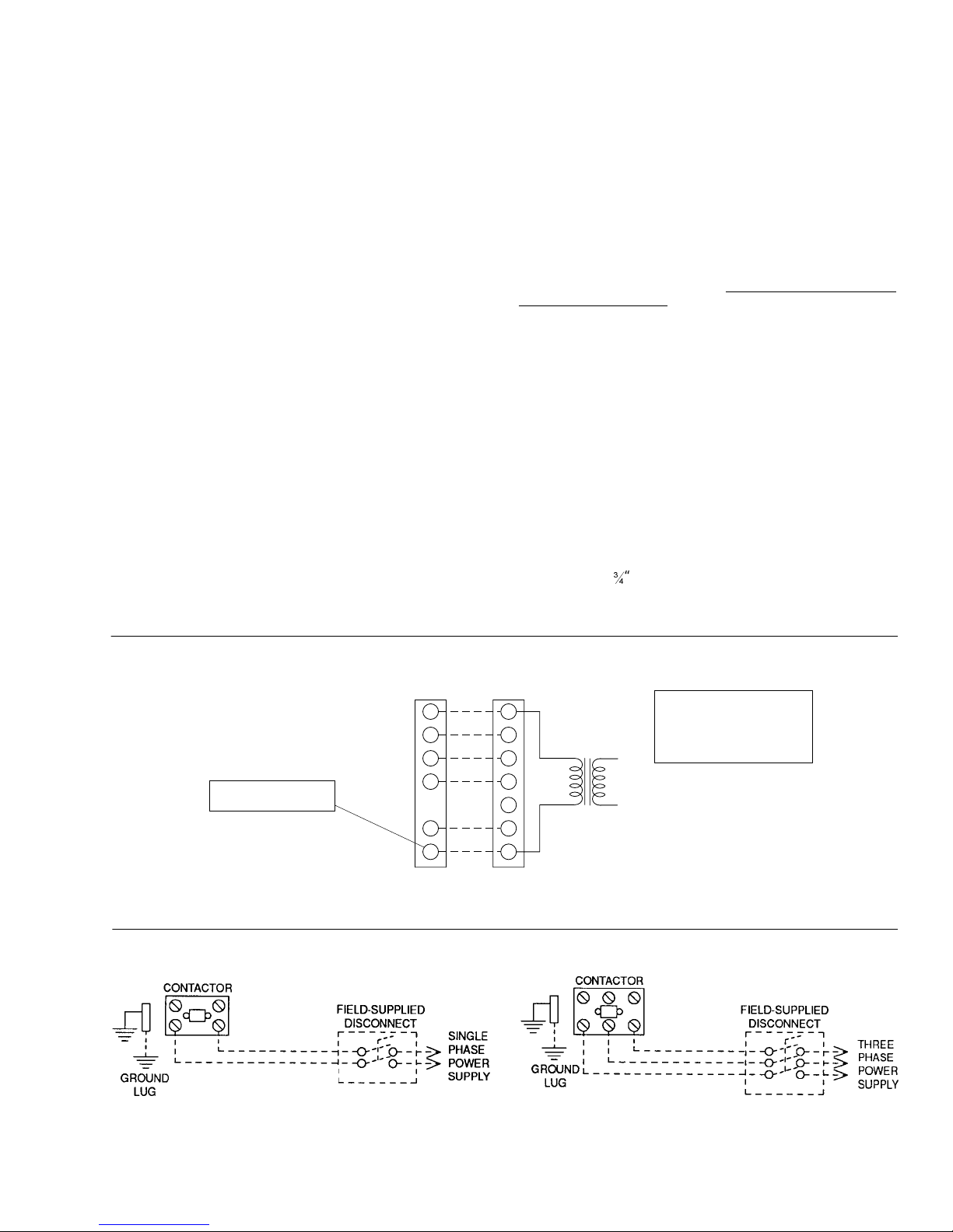
THERMOSTAT
** = Minimum wire size of 18 AWG
wire should be used for all field
installed 24 volt wire.
PROGRAMMABLE
THERMOSTAT ONLY
* = Only required on units with
supplemental electric heat.
CAUTION: Label all wires prior to disconnection when servicing controls. Wiring errors can
causeimproperand dangerousoperation.Verifyproperoperationafterservicing.
REFER TO ELECTRICAL DATA
TABLES TO SIZE THE DISCON
NECT SWITCH, WIRING &
OVERCURRENT PROTECTION.
-
FIG. 2 - TYPICAL FIELD WIRING DIAGRAM
CONTROL WIRING
UNIT TERMINAL STRIP
R
G
W
O O
C
R
**
G
YY
W2
*
W1
C
POWER WIRING
NOTE:
HEATANTICIPATOR
SHOULD BE SET AT 0.25
AMPS FOR ALL MODELS.
24 VOLTTRANSFORMER
REFER TO ELECTRICAL DATA TA
BLES TO SIZE THE DISCONNECT
SWITCH, WIRING & OVERCUR
RENT PROTECTION.
-
-
Unitary Products Group 3
Page 4

035-16004-001-A-0202
SERVICE ACCESS
Accessto allserviceablecomponents isprovidedby thefollow
ing removable panels:
Blower service access
•
Electrical/Filter access
•
Compressor service access
•
Refer to Figure3 for location of theseaccesspanels and mini
mum clearances.
THERMOSTAT
N.E.C./C.E.C. Voltage tolerances which must be maintained
at the compressor terminals during starting and running con
ditions are indicated on the unit Rating Plate and Table 3.
The wiring entering the cabinet must be provided with me
chanical strain relief.
Afused disconnect switch should be field provided for the unit.
-
If any of the wire supplied with the unit must be replaced, re
placement wire must be of the type shown on the wiring dia
gram.
-
-
-
-
The room thermostat should be located on an inside wall ap
proximately 56" above the floor where it will not be subject to
drafts, sun exposure or heat from electrical fixtures or appli
-
Electrical line must be sized properly to carry the load. Each
unit must be wired with a separate branch circuit fed directly
-
from the meter panel and properly fused.
ances. Follow manufacturer's instructions enclosed with the
thermostat for general installation procedure. Six color coded
insulated wires (minimum #18 AWG) should be used to con
nect thermostat to unit. See Figure 2.
POWER AND CONTROL WIRING
Field wiring to the unit must conform to provisions of the cur
rent N.E.C. ANSI/NFPANo. 70 or C.E.C. and/or local ordi
nances. The unit must be electrically grounded in
-
Refer to Figure 2 for typical field wiring and to the appropriate
-
unit wiring diagram for control circuit and power wiring informa
tion.
COMPRESSORS
-
Units are shipped with compressor mountings factoryadjusted for shipping. Caution: Loosen compressor bolts
half turn before operating unit.
accordance with local codes or, in their absence, with the
.
TABLE 2 - PHYSICAL DATA
BHA
3
1
4
4
3
4
1
4
3
4
1
4
INDOOR
BLOWER
INDOOR
COIL
OUTDOOR
FAN
OUTDOOR
COIL
MODELS
CENTRIFUGAL BLOWER (Dia. x Wd. in.) 9 X 6 10 X 8 10 X 8 10 x 8 11 X 10 11 X 10 11 X 10
FAN MOTOR HP(Three Speed)
ROWS DEEP 2233333
FINS PER INCH 15 13 13 15 15 16 16
FACE AREA(Sq. Ft.) 4.38 4.38 4.38 4.38 4.38 5.62 5.62
PROPELLER DIA. (in.) 22 22 22 22 22 22 22
FAN MOTOR HP
NOM. CFM TOTAL 1,800 1.800 1,800 2,400 2,400 2,800 2,800
ROWS DEEP 1111111
FINS PER INCH 20 20 20 20 20 16 20
FACE AREA(Sq. Ft.) 8.3 11.7 11.7 11.7 11.7 16.4 16.4
018 024 030 036 042 048 060
1
2
1
4
1
2
1
4
1
2
1
4
CHARGE REFRIGERANT22 (lbs./oz.) 4 / 12 5 / 12 7 / 8 5 / 5 5 / 5 9 / 0 10 / 0
FILTER FACE AREA (Sq. Ft. / Qty. / Size) 4.28 / 2 / 14" x 22"
COMPRESSOR HERMETIC Type, (Qty. = 1)
Reciprocating Reciprocating Scroll Scroll Scroll Scroll Scroll
-
1
1
4
TABLE 3 - ADDITIONAL STATIC PRESSURE RESISTANCE
DISCRIPTION
500 600 700 800 900 1,000 1,100 1,200 1,300 1,400 1,500 1,600 1,700 1,800 1,900 2,000
Wet Indoor coil 0.01 0.01 0.01 0.02 0.02 0.03 0.03 0.04 0.04 0.04 0.04 0.04 0.05 0.05 0.06 0.07
Economizer 0.00 0.00 0.00 0.01 0.01 0.01 0.01 0.02 0.03 0.04 0.05 0.06 0.07 0.07 0.08 0.08
Filter/Frame Kit 0.01 0.02 0.02 0.02 0.02 0.02 0.03 0.03 0.03 0.03 0.04 0.05 0.05 0.06 0.06 0.07
Electric Heat 0.02 0.03 0.03 0.03 0.04 0.04 0.05 0.06 0.07 0.08 0.09 0.10 0.01 0.11 0.11 0.12
NOTE: 1. Deduct these resistance values from the available external static pressure shown in the respective Blower Performance Table.
2. The pressure thru the economizer is greater for 100% outdoor air then for 100% return air. If the resistance of the return air duct system is less then 0.25 IWG, the unit will deliver
less CFM during full economizer operation.
4 Unitary Products Group
RESISTANCE, IWG
CFM
Page 5
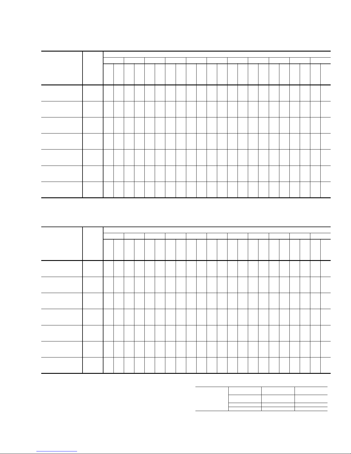
TABLE 4 - SIDE AND BOTTOM SUPPLY AIR BLOWER PERFORMANCE
230/460/575 volts
EXTERNAL STATIC PRESSURE - IWG
MODEL NO.
BHA
MOTOR
SPEED
HI
018
MED
LOW
HI
024
MED
LOW
HI
030
MED
LOW
HI
036
MED
LOW
HI
042
MED
LOW
HI
048
MED
LOW
HI
060
MED
LOW
NOTE: Above data includes allowances for a dry indoor coil and no filters. For additional pressure drops, refer to the “Additional Static Pressure Resistance” table.
.10 .20 .30 .40 .50 .60 .70 .80 .90 1.00 1.10
CFM
-
-
-
-
-
900
-
1200
900
-
-
1462
-
-
-
1876
1544
-
2242
-
-
-
-
-
290
390
280
-
526
-
-
-
792
620
-
-
1090
WATTS
1134
1400
1680
1829
1508
2454
2201
-
-
-
-
-
850
-
850
-
-
-
-
-
-
CFM
287
397
267
506
607
772
610
1163
1053
-
-
-
-
-
-
-
-
-
-
-
-
WATTS
1068
1472
1337
1608
1783
1472
2387
2161
-
-
702
-
-
800
-
800
-
-
-
-
-
CFM
220
243
368
243
647
486
584
753
600
1117
1017
-
-
-
-
-
-
-
-
-
-
WATTS
1002
1394
1275
1673
1630
1947
1736
1436
2499
2320
2120
641
760
CFM
-
-
-
-
-
-
-
-
-
-
206
-
-
220
-
367
-
626
467
830
660
882
733
590
1290
1070
980
WATTS
1414
1297
1167
1697
1566
1425
1867
1668
1375
2391
2229
2041
654
536
935
697
936
-
CFM
233
183
338
238
339
617
495
440
740
594
528
857
706
573
1233
1023
927
-
-
-
-
WATTS
1200
1317
1199
1100
1580
1439
1320
1786
1599
1313
2283
2137
1962
668
541
-
867
843
897
-
CFM
401
209
322
183
640
322
688
465
414
706
558
496
832
680
557
1177
977
873
-
-
-
WATTS
1100
1219
1102
1012
1463
1322
1214
1706
1531
1252
2175
2046
1883
652
-
-
-
800
-
800
-
CFM
386
304
620
304
660
435
387
672
522
464
807
653
540
1120
930
820
-
-
-
-
-
WATTS
1116
1339
1182
1050
1637
1434
2067
1950
1797
-
-
-
987
733
-
987
-
-
985
-
-
CFM
507
286
507
533
397
640
476
420
782
622
1080
887
787
-
-
-
-
-
-
-
-
WATTS
1013
1216
1569
1337
1958
1854
1711
CFM
-
-
-
873
867
-
873
-
-
-
-
-
-
1040
035-16004-001-A-0202
493
268
493
507
608
757
591
843
753
-
-
-
-
-
-
-
-
-
-
-
WATTS
1092
1500
1240
1850
1758
1625
CFM
-
-
-
760
-
-
760
-
-
910
-
-
-
-
-
-
-
-
480
-
-
480
-
-
480
-
-
576
-
-
732
560
-
1000
800
720
WATTS
CFM
-
-
-
-
-
-
-
-
-
-
-
-
-
-
-
-
-
-
-
-
-
WATTS
-
-
-
-
-
-
-
-
-
-
-
-
-
-
-
-
-
-
-
-
-
208 volts
EXTERNAL STATIC PRESSURE - IWG
MODEL NO.
BHA
MOTOR
SPEED
HI
018
MED
LOW
HI
024
MED
LOW
HI
030
MED
LOW
HI
036
MED
LOW
HI
042
MED
LOW
HI
048
MED
LOW
HI
060
MED
LOW
NOTE: Above data includes allowances for a dry indoor coil and no filters. For additional pressure drops, refer to the “Additional Static Pressure Resistance” table.
.10 .20 .30 .40 .50 .60 .70 .80 .90 1.00 1.10
CFM
-
-
741
-
-
810
-
1080
810
1465
1316
-
1679
1694
1385
2339
1929
-
-
226
-
-
261
351
261
631
473
-
867
690
520
-
1170
940
WATTS
1021
1395
1260
1674
1612
1982
1662
1349
2275
1877
-
-
686
-
-
765
-
766
-
-
-
CFM
212
240
341
240
512
455
614
646
870
673
510
1118
903
-
-
-
-
-
-
-
-
WATTS
1440
1325
1204
1728
1590
1449
1939
1629
1312
2450
2211
1824
-
-
632
961
720
961
-
CFM
198
351
219
331
608
492
438
725
590
526
850
657
500
1213
1067
867
-
-
-
-
-
WATTS
1381
1255
1148
1633
1506
1377
1897
1597
1276
2366
2147
1772
690
577
902
675
902
CFM
-
-
-
-
231
185
321
198
321
581
473
420
697
567
504
830
640
490
1165
1015
830
WATTS
1171
1273
1167
1069
1527
1400
1282
1813
1542
1235
2282
2083
1720
689
659
453
841
627
841
-
CFM
374
210
165
305
215
604
306
656
446
396
666
636
476
800
623
480
1117
963
793
-
-
WATTS
1080
1185
1079
1422
1296
1188
1728
1486
2198
2019
1667
593
487
-
-
751
-
781
-
990
-
CFM
361
188
290
486
280
530
419
372
636
602
447
770
607
1068
912
757
-
-
-
-
-
WATTS
1097
1317
1190
1093
1644
1431
2114
1955
1615
497
-
-
990
720
-
980
-
-
952
911
-
CFM
347
468
274
468
604
392
348
606
470
418
740
590
1020
860
720
-
-
-
-
-
-
WATTS
1004
1205
1063
1559
1336
1989
1854
1586
-
-
-
888
660
-
888
-
-
-
-
-
-
CFM
456
257
456
480
676
428
707
563
993
824
706
-
-
-
-
-
-
-
-
-
-
WATTS
1094
1474
1240
1864
1753
1557
CFM
-
-
-
786
-
-
786
-
-
912
-
-
-
-
-
444
444
456
547
673
537
967
788
691
-
-
-
-
-
-
-
-
-
-
-
-
WATTS
1389
1739
1652
1528
-
-
-
684
-
-
-
-
-
-
-
-
-
-
-
-
-
CFM
432
640
940
752
677
-
-
-
-
-
-
-
-
-
-
-
-
-
-
-
-
WATTS
CFM
-
-
-
-
-
-
-
-
-
-
-
-
-
-
-
-
-
-
-
-
-
WATTS
-
-
-
-
-
-
-
-
-
-
-
-
-
-
-
-
-
-
-
-
-
Unitary Products Group 5
ELECTRIC HEAT
CORRECTION
FACTORS
NOMINAL VOLTAGE VOLTAGE
240
480 460 .92
600 575 .92
208
230
KW CAP. MULTI
PLIER
.75
.92
-
Page 6

035-16004-001-A-0202
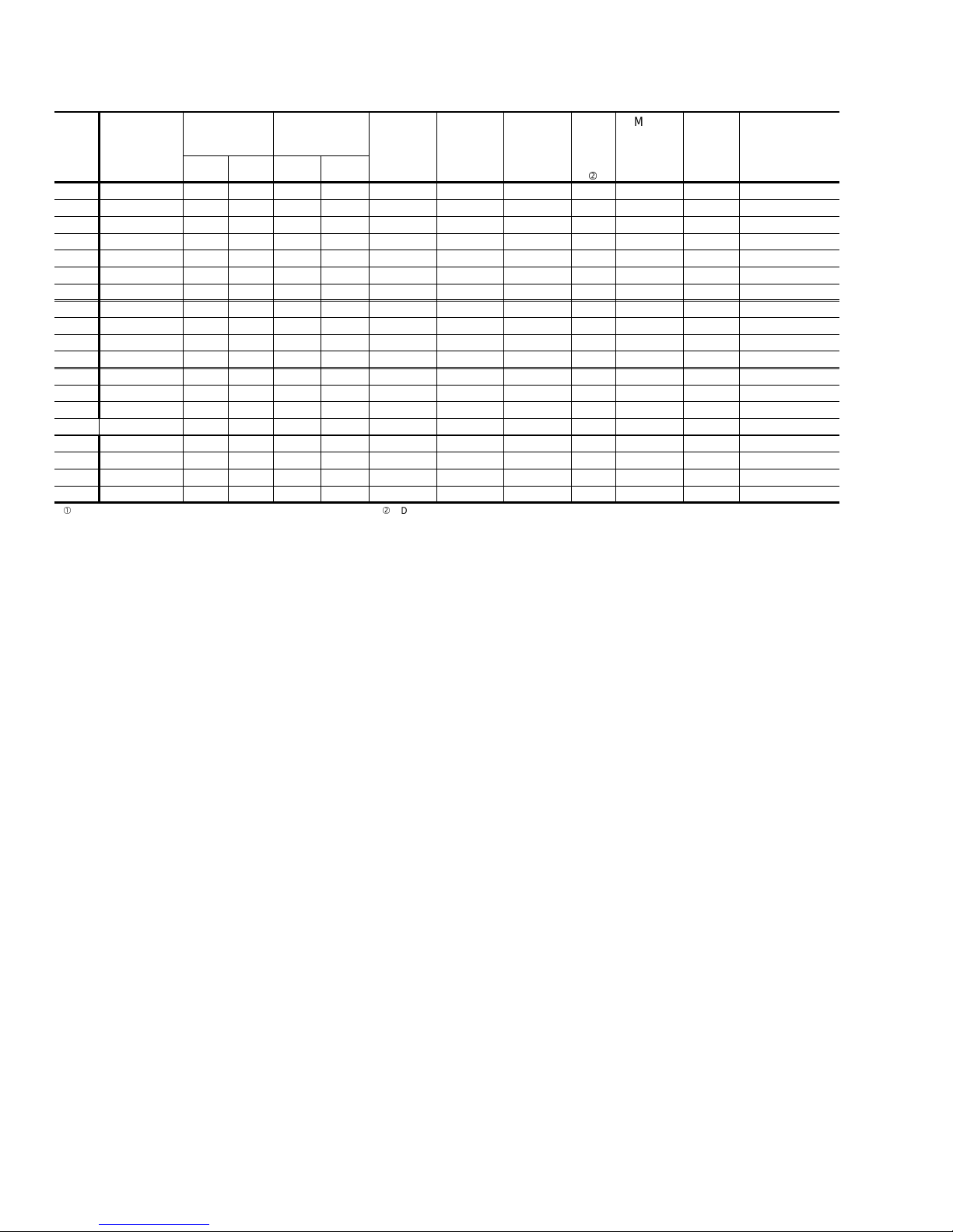
TABLE 5 - ELECTRICAL DATA(HEAT PUMP / ELECTRIC HEAT)
ELECTRIC HEATACCESSORY
STAGE
2NH04500506
2NH0450070612
2NH04500506
2NH04500706
2NH04501006
2NH04500506
2NH04500706
2NH04501006
2NH04501506
2ND04501506 2
2NH04500506
2NH04500706
2NH04501006
2NH04501506
2ND04501506 2
2NH04500506
2NH04500706
2NH04501006
2NH04501506
2ND04501506 2
2NH04501006
2NH04501506
2NH04502006
2NH04502506
2NH04501006
2NH04501506
2NH04502006
2NH04502506
2NH04501025
2NH0450152511
2NH04501025
2NH0450152511
2NH04501025
2NH04501525
2NH04502025
2NH04502525
2NH04501025
2NH04501525
2NH04502025
2NH04502525
2NH04501046
2NH0450154611
2NH04501046
2NH0450154611
2NH04501046
2NH04501546
2NH04502046
2NH04502546
2NH04501046
2NH04501546
2NH04502046
2NH04502546
3.8/5.0 *
5.6/7.5 *
3.8/5.0 *
1
5.6/7.5 *
2
7.5/10.0 *
2
3.8/5.0 *
1
5.6/7.5 *
2
7.5/10.0 *
2
11.3/15.0 *
2
3.8/5.0 18.1/20.8 44.7/48.2 50/50 50/50
3.8/5.0 *
1
5.6/7.5 *
2
7.5/10.0 *
2
11.3/15.0 *
2
3.8/5.0 18.1/20.8 48.8/52.3 60/60 60/60
3.8/5.0 *
1
5.6/7.5 *
2
7.5/10.0 *
2
11.3/15.0 *
2
3.8/5.0 18.1/20.8 52.8/56.3 60/70 60/70
7.5/10.0 *
2
11.3/15.0 *
2
15.0/20.0 *
2
18.8/25.0 *
2
7.5/10.0 *
2
11.3/15.0 *
2
15.0/20.0 *
2
18.8/25.0 *
2
7.5/10.0 *
11.3/15.0 *
7.5/10.0 *
11.3/15.0 *
7.5/10.0 *
1
11.3/15.0 *
1
15.0/20.0 *
2
18.8/25.0 *
2
7.5/10.0 *
1
11.3/15.0 *
1
15.0/20.0 *
2
18.8/25.0 *
2
10.0 **
15.0 **
10.0 **
15.0 **
10.0 **
1
15.0 **
1
20.0 **
2
25.0 **
2
10.0 **
1
15.0 **
1
20.0 **
2
25.0 **
2
KW
TOTAL
AMPS
18.1/20.8
27.1/31.3
18.1/20.8
27.1/31.3
36.1/41.7
18.1/20.8
27.3/31.3
36.1/41.7
54.2/62.5
18.1/20.8
27.1/31.3
36.1/41.7
54.2/62.5
18.1/20.8
27.1/31.3
36.1/41.7
54.2/62.5
36.1/41.7
54.2/62.5
72.2/83.3
90.3/104.2
36.1/41.7
54.2/62.5
72.2/83.3
90.3/104.2
20.8/24.1
31.3/36.1
20.8/24.1
31.3/36.1
20.8/24.1
31.3/36.1
41.7/48.1
52.1/60.1
20.8/24.1
31.3/36.1
41.7/48.1
52.1/60.1
12.8
18.0
12.0
18.0
12.0
18.0
24.1
30.1
12.0
18.0
24.1
30.1
MINIMUM
CIRCUIT
AMPACITY
37.5/41.0
48.8/54.0
40.7/44.2
52.0/57.2
63.3/70.2
44.7/48.2
56.0/61.2
67.3/74.2
89.8/100.3
48.8/52.3
60.1/65.3
71.4/78.3
93.9/104.4
52.8/56.3
64.1/69.3
75.4/82.3
97.9/108.4
81.1/88.1
103.7/114.1
126.3/140.2
148.8/166.2
89.8/96.7
112.3/122.8
134.9/148.8
157.5/174.8
44.3/48.3
57.3/63.3
48.3/57.3
61.3/67.3
49.2/53.2
62.2/68.2
75.3/83.3
88.3/98.3
54.6/58.6
67.6/73.6
80.7/88.7
93.7/103.7
24.6
32.2
26.2
33.8
26.7
34.2
41.7
49.3
29.4
36.9
44.4
51.9
MAX.
FUSE
SIZE,
AMPS
40/45
50/60
45/50
60/60
70/80
50/50
60/70
70/80
90/110
60/60
70/70
80/80
100/110
60/70
70/80
80/90
100/110
90/100
110/125
150/150
150/175
100/110
125/125
150/150
175/175
45/50
60/70
50/60
70/70
50/60
70/70
80/90
90/100
60/60
70/80
90/90
100/110
25
35
30
35
30
35
45
50
30
40
45
60
HACR
BREAKER
100/110
100/110
110/125
150/150
150/175
100/110
125/125
150/150
175/175
100/110
BHA
POWER
SUPPLY
COMPRESSOR
OUTDOOR
FAN
MOTOR
RLA LRA MODEL NO.
FLA
SUPPLY
AIR
BLOWER
MOTOR,
FLA
MODEL
018 208/230-1-60 9.0 48.0 1.1 2.6
024 208/230-1-60 11.2 60.0 1.1 2.6
14.7 73.0 1.1 2.6
030 208/230-1-60
14.7 73.0 1.1 2.6
0.0 0.0 0.0 0.0 7.5/10.0 36.1/41.7 45.1/52.1 50/60 50/60
17.3 94.0 1.1 3.5
036 208/230-1-60
17.3 94.0 1.1 3.5
0.0 0.0 0.0 0.0 7.5/10.0 36.1/41.7 45.1/52.1 50/60 50/60
20.5 120.0 1.1 3.5
042 208/230-1-60
20.5 120.0 1.1 3.5
0.0 0.0 0.0 0.0 7.5/10.0 36.1/41.7 45.1/52.1 50/60 50/60
048 208/230-1-60 24.4 140.0 1.5 4.0
060 208/230-1-60 28.9 165.0 1.5 7.0
036 208/230-3-60 10.9 78.0 1.1 3.5
042 208/230-3-60 14.1 110.0 1.1 3.5
048 208/230-3-60 14.1 105.0 1.5 4.0
060 208/230-3-60 16.0 125.0 1.5 7.0
036 460-3-60 5.8 40.0 0.6 1.8
042 460-3-60 7.1 54.0 0.6 1.8
048 460-3-60 7.1 55.0 0.8 2.0
060 460-3-60 8.0 67.0 0.8 3.5
= Dual element, time delay type. * = KW listed is for 240 volts, use table at top of page for 208 or 230 volts.
= Standard circuit breakers may be used in Canada and on applications ** = KW listed is for 480 volts, use table at top of page for 460 volts.
over 60 amps where the heaters are separately fused. *** = KW listed is for 600 volts, use table at top of page for 575 volts.
MAX.
SIZE
40/45
50/60
45/50
60/60
70/80
50/50
60/70
70/80
90/110
60/60
70/70
80/80
60/70
70/80
80/90
90/100
45/50
60/70
50/60
70/70
50/60
70/70
80/90
90/100
60/60
70/80
90/90
25
35
30
35
30
35
45
50
30
40
45
60
6 Unitary Products Group
Page 7
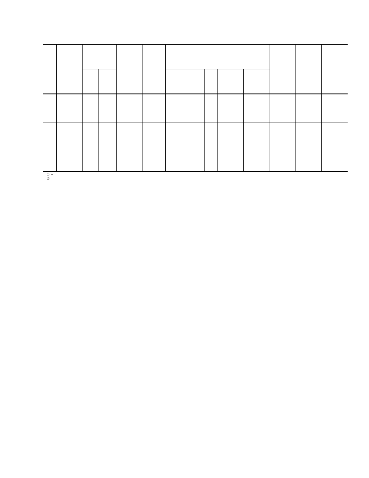
TABLE 5 - ELECTRICAL DATA(HEAT PUMP / ELECTRIC HEAT) (Continued)
035-16004-001-A-0202
COMPRES
BHA
POWER
SUPPLY
RLA LRA MODEL NO.
MODEL
036 575-3-60 4.5 32.0 0.4 1.5
042 575-3-60 5.8 44.0 0.4 1.5
048 575-3-60 5.6 44.0 0.6 1.6
060 575-3-60 6.4 50.0 0.6 2.8
= Dual element, time delay type. * = KW listed is for 240 volts, use table at top of page for 208 or 230 volts.
= Standard circuit breakers may be used in Canada and on applications ** = KW listed is for 480 volts, use table at top of page for 460 volts.
over 60 amps where the heaters are separately fused. *** = KW listed is for 600 volts, use table at top of page for 575 volts.
SOR
OUT
DOOR
FAN
MOTOR
FLA
-
SUPPLY
AIR
BLOWE
R
MOTOR,
FLA
ELECTRIC HEATACCESSORY
STAGE
2NH04501058
2NH0450155811
2NH04501058
2NH0450155811
2NH04501058
2NH04501558
2NH04502058
2NH04502558
2NH04501058
2NH04501558
2NH04502058
2NH04502558
1
1
2
2
1
1
2
2
KW
10.0 ***
15.0 ***
10.0 ***
15.0 ***
10.0 ***
15.0 ***
20.0 ***
25.0 ***
10.0 ***
15.0 ***
20.0 ***
25.0 ***
TOTAL
AMPS
9.6
14.4
9.6
14.4
9.6
14.4
19.2
24.1
9.6
14.4
19.2
24.1
MINIMUM
CIRCUIT
AMPAC
ITY
19.6
25.6
21.1
27.2
21.3
27.3
33.3
39.3
23.4
29.5
35.5
41.5
-
MAX.
FUSE
SIZE,
AMPS
20
30
25
30
25
30
35
40
25
30
40
45
HACR
BREAKER
MAX.
SIZE
20
30
25
30
25
30
35
40
25
30
40
45
Unitary Products Group 7
Page 8
035-16004-001-A-0202
TABLE 6 - ELECTRICAL DATA(BASIC UNIT)
MAX.
FUSE
SIZE,
AMPS
MAX.
HACR
BREAKER
SIZE,
AMPS
UNIT
POWER
FACTOR
TRANSFORMER
MODEL
BHA
POWER SUP
PLY
VOLTAGE
LIMITATIONSCOMPRESSOR
MIN. MAX. RLA LRA
OUTDOOR
FAN
MOTOR,
FLA
SUPPLY
AIR
BLOWER
MOTOR,
FLA
MINIMUM
CIRCUIT
AMPACITY
018 208/230-1-60 187 253 9.0 48.0 1.1 2.6 14.9 20 20 .96 40
024 208/230-1-60 187 253 11.2 60.0 1.1 2.6 17.7 25 25 .96 40
030 208/230-1-60 187 253 12.0 73.0 1.1 2.6 18.7 25 25 .96 40
036 208/230-1-60 187 253 17.3 94.0 1.1 3.5 26.2 35 35 .96 40
042 208/230-1-60 187 253 20.5 120.0 1.1 3.5 30.2 40 40 .96 40
048 208/230-1-60 187 253 24.4 140.0 1.5 4.0 36.0 50 50 .96 40
060 208/230-1-60 187 253 28.9 165.0 1.5 7.0 44.6 60 60 .96 40
036 208/230-3-60 187 253 10.9 78.0 1.1 3.5 18.2 25 25 .96 75
042 208/230-3-60 187 253 14.1 110.0 1.1 3.5 22.2 30 30 .96 75
048 208/230-3-60 187 253 14.1 105.0 1.5 4.0 23.1 30 30 .96 75
060 208/230-3-60 187 253 16.0 125.0 1.5 7.0 28.5 40 40 .96 75
036 460-3-60 414 504 5.8 40.0 0.6 1.8 9.6 15 15 .96 75
042 460-3-60 414 504 7.1 54.0 0.6 1.8 11.2 15 15 .96 75
048 460-3-60 414 504 7.1 55.0 0.8 2.0 11.7 15 15 .96 75
060 460-3-60 414 504 8.0 67.0 0.8 3.5 14.3 20 20 .96 75
036 575-3-60 518 630 4.5 32.0 0.4 1.5 7.6 15 15 .96 75
042 575-3-60 518 630 5.8 44.0 0.4 1.5 9.1 15 15 .96 75
048 575-3-60 518 630 5.6 44.0 0.6 1.6 9.3 15 15 .96 75
060 575-3-60 518 630 6.4 50.0 0.6 2.8 11.4 15 15 .96 75
= Rated in accordance with ARI Standard 110, utilization range “A”.
= Dual element, time delay type.
SIZE (VA)
8 Unitary Products Group
Page 9

Checking Supply Air CFM
To check the supply air CFM after the initial balancing has
been completed:
1.Remove the two ¼ inch dot plugs in the duct panel.
035-16004-001-A-0202
curate. To ensure a dry coil, the compressors should be de
activated while the test is being run.
4.Knowing the pressure drop across a dry coil, the actual
CFM through the unit can be determined from the curve in
Coil Delta P vs. Supply Air CFM figure.
-
2.Insert at least 8 inches of ¼ inch tubing into each of these
holes for sufficient penetration into the airflow on both sides
of the indoor coil.
3.Using an inclined manometer, determine the pressure drop
across the dry evaporator coil. Since the moisture on an
evaporator coil may vary greatly, measuring the pressure
drop across a wet coil under field conditions would be inac
0.4
0.35
0.3
0.25
0.2
DeltaStatic(IWG)
0.15
0.1
B1HA024 B1HA030-36B1HA018
-
B1HA Coil Delta
WARNING! Failure to properly adjust the total system air
quantity can result in extensive system damage.
After readings have been obtained, remove the tubes and
reinstall the two ¼ inch plugs removed in Step 1.
NOTE: De-energize the compressors before taking any test
measurements to ensure a dry indoor coil.
B1HA048-60
B1HA042
B1HA018
B1HA024
B1HA042
B1HA030-36
B1HA048-60
Linear (B1HA018)
Linear (B1HA024)
Linear (B1HA030-36)
Linear (B1HA042)
Linear (B1HA048-60)
0.05
0
0 500 1000 1500 2000 2500
Airflow (CFM)
Unitary Products Group 9
Page 10

035-16004-001-A-0202
TABLE 7 - COOLING SUPERHEAT AT COMPRESSOR SUCTION, AIRFLOW = 600 CFM (B1HA018)
OUTDOOR
TEMPERATURE,
°F
65 9.2 14.5 19.7 25.0 30.2 35.5 40.8 40.3 39.7 39.2 38.7
70 9.6 14.2 18.8 23.4 28.0 32.5 37.1 37.3 37.5 37.7 37.9
75 10.1 14.0 17.9 21.8 25.7 29.5 33.4 34.3 35.2 36.1 37.0
80 10.5 13.7 17.0 20.2 23.4 26.6 29.8 31.4 33.0 34.6 36.2
85 11.0 13.5 16.0 18.5 21.1 23.6 26.1 28.4 30.7 33.0 35.4
90 11.4 13.3 15.1 16.9 18.8 20.6 22.4 25.5 28.5 31.5 34.5
95 11.9 13.0 14.2 15.3 16.5 17.6 18.8 22.5 26.2 30.0 33.7
100 9.0 10.3 11.7 13.1 14.4 15.8 17.1 20.1 23.0 26.0 28.9
105 6.0 7.6 9.2 10.8 12.4 14.0 15.5 17.7 19.8 22.0 24.1
110 - - 6.7 8.5 10.3 12.1 13.9 15.3 16.6 18.0 19.3
115 - - - 6.3 8.3 10.3 12.3 12.9 13.4 14.0 14.5
55 57 59 61 63 65 67 69 71 73 75
INDOOR WB TEMPERATURE, °F
TABLE 8 - HEATING SUPERHEAT ATCOMPRESSOR SUCTION, AIRFLOW = 600 CFM (B1HA018)
INDOOR DB
TEMPERATURE,
°F
55 9.7 10.2 10.9 12.1 14.2 17.6 23.3 32.8
70 - - - 3.0 5.1 8.5 14.2 23.7
80 -----4.19.819.3
-100 102030405060
OUTDOOR TEMPERATURE, °F
10 Unitary Products Group
Page 11

TABLE 9 - COOLING SUPERHEAT AT COMPRESSOR SUCTION, AIRFLOW = 800 CFM (B1HA024)
035-16004-001-A-0202
OUTDOOR
TEMPERATURE,
°F
65 17.0 18.2 19.4 20.5 21.7 22.8 24.0 27.0 30.0 33.0 36.0
70 14.3 15.5 16.7 17.8 19.0 20.1 21.3 24.6 27.9 31.1 34.4
75 11.6 12.8 13.9 15.1 16.3 17.4 18.6 22.2 25.7 29.3 32.9
80 8.9 10.1 11.2 12.4 13.6 14.7 15.9 19.7 23.6 27.5 31.4
85 6.2 7.4 8.5 9.7 10.9 12.0 13.2 17.3 21.5 25.7 29.9
90 - - 5.8 7.0 8.2 9.3 10.5 14.5 19.4 23.9 28.3
95 ----5.56.67.812.5 17.3 22.1 26.8
100 -----5.46.310.4 14.6 18.7 22.9
105 -------8.311.815.4 19.0
110 -------6.29.112.1 15.0
115 --------6.48.811.1
55 57 59 61 63 65 67 69 71 73 75
INDOOR WB TEMPERATURE, °F
TABLE 10 - HEATING SUPERHEAT ATCOMPRESSOR SUCTION, AIRFLOW = 800 CFM (B1HA024)
INDOOR DB
TEMPERATURE,
°F
55 12.6 13.0 13.5 14.2 15.4 17.2 19.9 24.2
70 ----3.35.17.912.1
80 ------4.99.1
-100 102030405060
HEATING SUPERHEAT AT COMPRESSOR SUCTION, °F
TABLE 11 - COOLING SUPERHEAT AT COMPRESSOR SUCTION, AIRFLOW = 1,000 CFM (B1HA030)
OUTDOOR
TEMPERATURE,
°F
65 17.0 20.0 22.9 25.9 28.9 31.8 34.8 39.0 43.1 47.3 51.5
70 14.3 16.9 19.5 22.2 24.8 27.5 30.1 34.2 38.2 42.3 46.4
75 11.5 13.9 16.2 18.5 20.8 23.1 25.4 29.4 33.4 37.3 41.3
80 8.8 10.8 12.8 14.8 16.7 18.7 20.7 24.6 28.5 32.3 36.2
85 6.1 7.7 9.4 11.0 12.7 14.4 16.0 19.8 23.6 27.4 31.1
90 - - 6.0 7.3 8.7 10.0 11.3 15.0 18.7 22.4 26.1
95 -----5.66.610.2 13.8 17.4 21.0
100 ------5.27.910.7 13.4 16.2
105 -------5.67.69.511.4
110 ---------5.66.7
115 -----------
55 57 59 61 63 65 67 69 71 73 75
INDOOR WB TEMPERATURE, °F
TABLE 12 - HEATING SUPERHEAT ATCOMPRESSOR SUCTION, AIRFLOW = 1,000 CFM (B1HA030)
INDOOR DB
TEMPERATURE,
°F
55 15.3 15.6 16.0 16.8 17.9 19.6 22.2 26.2
70 ----3.24.97.511.5
80 ------4.58.5
-100 102030405060
OUTDOOR TEMPERATURE, °F
Unitary Products Group 11
Page 12

035-16004-001-A-0202
TABLE 13 - COOLING SUPERHEAT AT COMPRESSOR SUCTION, AIRFLOW = 1,200 CFM (B1HA036)
OUTDOOR
TEMPERATURE,
°F
65 12.8 16.1 19.3 22.5 25.8 29.0 32.2 35.0 37.7 40.4 43.1
70 11.4 14.3 17.2 20.1 22.9 25.8 28.7 31.6 34.4 37.3 40.1
75 9.9 12.5 15.0 17.6 20.1 22.7 25.2 28.2 31.1 34.1 37.1
80 8.5 10.7 12.9 15.1 17.3 19.5 21.7 24.8 27.9 31.0 34.0
85 7.0 8.9 10.8 12.6 14.5 16.3 18.2 21.4 24.6 27.8 31.0
90 5.6 7.1 8.6 10.1 11.7 13.2 14.7 18.0 21.3 24.7 28.0
95 - 5.3 6.5 7.7 8.8 10.0 11.2 14.6 18.1 21.5 25.0
100 - - 5.1 6.0 6.9 7.8 8.7 11.7 14.7 17.7 20.7
105 -----5.66.28.711.313.9 16.4
110 -------5.87.910.0 12.2
115 ---------6.27.9
55 57 59 61 63 65 67 69 71 73 75
INDOOR WB TEMPERATURE, °F
TABLE 14 - HEATING SUPERHEAT ATCOMPRESSOR SUCTION, AIRFLOW = 1,200 CFM (B1HA036)
INDOOR DB
TEMPERATURE,
°F
55 9.7 10.1 10.7 11.8 13.7 17.0 22.6 32.2
70 ----4.67.813.4 23.0
80 ------7.316.9
-100 102030405060
HEATING SUPERHEAT AT COMPRESSOR SUCTION, °F
TABLE 15 - COOLING SUPERHEAT AT COMPRESSOR SUCTION, AIRFLOW = 1,400 CFM (B1HA042)
OUTDOOR
TEMPERATURE,
°F
65 34.0 34.2 34.4 34.6 34.8 35.0 35.2 36.2 37.3 38.4 39.4
70 31.1 31.5 31.9 32.2 32.6 33.0 33.4 34.8 36.3 37.7 39.2
75 28.3 28.8 29.4 29.9 30.5 31.0 31.6 33.4 35.3 37.1 39.0
80 25.4 26.1 26.9 27.6 28.3 29.1 29.8 32.0 34.3 36.5 38.7
85 22.6 23.5 24.4 25.3 26.2 27.1 28.0 30.6 33.2 35.9 38.5
90 19.7 20.8 21.9 23.0 24.0 25.1 26.2 29.2 32.2 35.2 38.3
95 16.9 18.1 19.4 20.6 21.9 23.2 24.4 27.8 31.2 34.6 38.0
100 14.5 15.6 16.6 17.7 18.7 19.7 20.8 24.4 27.9 31.5 35.1
105 12.2 13.1 13.9 14.7 15.5 16.3 17.1 20.9 24.6 28.4 32.1
110 9.9 10.5 11.1 11.7 12.3 12.9 13.5 17.4 21.3 25.3 29.2
115 7.6 8.0 8.4 8.8 9.1 9.5 9.9 14.0 18.1 22.1 26.2
55 57 59 61 63 65 67 69 71 73 75
INDOOR WB TEMPERATURE, °F
TABLE 16 - HEATING SUPERHEAT ATCOMPRESSOR SUCTION, AIRFLOW = 1,400 CFM (B1HA042)
INDOOR DB
TEMPERATURE,
°F
55 5.1 5.5 6.2 7.4 9.6 13.5 20.3 32.4
70 ----5.08.915.7 27.8
80 -----5.412.2 24.3
-100 102030405060
OUTDOOR TEMPERATURE, °F
12 Unitary Products Group
Page 13

TABLE 17 - COOLING SUPERHEAT AT COMPRESSOR SUCTION, AIRFLOW = 1,600 CFM (B1HA048)
035-16004-001-A-0202
OUTDOOR
TEMPERATURE,
°F
65 11.4 12.4 13.5 14.6 15.7 16.8 17.9 19.3 20.7 22.1 23.5
70 10.3 11.2 12.2 13.1 14.0 14.9 15.9 17.4 18.9 20.4 21.9
75 9.3 10.0 10.8 11.6 12.3 13.1 13.9 15.4 17.0 18.6 20.2
80 8.2 8.8 9.4 10.0 10.6 11.2 11.8 13.5 15.2 16.9 18.5
85 7.2 7.7 8.1 8.5 9.0 9.4 9.8 11.6 13.4 15.1 16.9
90 6.5 7.0 7.4 7.9 8.3 8.8 9.2 10.6 12.0 13.4 14.8
95 5.9 6.3 6.8 7.2 7.7 8.1 8.6 9.6 10.6 11.6 12.6
100 - 5.5 6.1 6.6 7.2 7.8 8.4 9.3 10.3 11.3 12.3
105 - - 5.4 6.1 6.8 7.5 8.2 9.1 10.1 11.0 11.9
110 - - - 5.5 6.3 7.2 8.0 8.9 9.8 10.7 11.6
115 ----5.96.97.88.79.510.4 11.2
55 57 59 61 63 65 67 69 71 73 75
INDOOR WB TEMPERATURE, °F
TABLE 18 - HEATING SUPERHEAT ATCOMPRESSOR SUCTION, AIRFLOW = 1,600 CFM (B1HA048)
INDOOR DB
TEMPERATURE,
°F
55 8.3 8.4 8.6 9.0 10.1 12.4 17.4 28.6
70 -----4.29.220.4
80 ------5.716.9
-100 102030405060
HEATING SUPERHEAT AT COMPRESSOR SUCTION, °F
TABLE 19 - COOLING SUPERHEAT AT COMPRESSOR SUCTION, AIRFLOW = 2,000 CFM (B1HA060)
OUTDOOR
TEMPERATURE,
°F
65 26.7 27.6 28.5 29.4 30.3 31.2 32.1 33.0 33.9 34.8 35.7
70 21.9 23.0 24.1 25.2 26.3 27.4 28.5 30.0 31.4 32.8 34.3
75 17.0 18.3 19.7 21.0 22.3 23.7 25.0 27.0 28.9 30.9 32.9
80 12.2 13.7 15.3 16.8 18.4 19.9 21.5 24.0 26.5 29.0 31.4
85 7.3 9.1 10.8 12.6 14.4 16.2 17.9 20.9 24.0 27.0 30.0
90 7.2 8.3 9.4 10.6 11.7 12.8 13.9 17.3 20.6 23.9 27.2
95 7.0 7.5 8.0 8.5 9.0 9.5 9.9 13.6 17.2 20.8 24.4
100 7.2 7.6 8.0 8.3 8.7 9.1 9.5 12.4 15.3 18.2 21.1
105 7.4 7.7 7.9 8.2 8.5 8.7 9.0 11.2 13.4 15.6 17.8
110 7.6 7.8 7.9 8.1 8.2 8.4 8.5 10.0 11.5 13.0 14.4
115 7.8 7.8 7.9 7.9 8.0 8.0 8.1 8.8 9.6 10.3 11.1
55 57 59 61 63 65 67 69 71 73 75
INDOOR WB TEMPERATURE, °F
TABLE 20 - HEATING SUPERHEAT ATCOMPRESSOR SUCTION, AIRFLOW = 2,000 CFM (B1HA060)
INDOOR DB
TEMPERATURE,
°F
55 5.5 5.7 6.2 6.8 8.0 9.9 13.1 18.6
70 -----4.88.013.4
80 ------5.611.0
-100 102030405060
OUTDOOR TEMPERATURE, °F
Unitary Products Group 13
Page 14

035-16004-001-A-0202
HIGH VOLTAGE CONN.
31
1
LOW VOLTAGE CONN.
7
“ DIA. KNOCKOUT
8
SIDE SUPPLY
AIR OPENING
SIDE RETURN
AIR OPENING
LOW VOLTAGE
CONN.
7
“ DIA. KNOCK
8
-
HIGH VOLTAGE CONN.
7
" DIA. KNOCKOUT
8
" DIA. KNOCKOUT
32
(OVERALL)
FRONT
COMPRESSOR
SERVICE ACCESS
COMPARTMENTPANEL
DIMENSION
“A”
1
33
2
1
41
2
3
2
“A”
8
(OVERALL)
UNIT SIZE
018 - 042
048 - 060
REFRIGERANT
CONNECTIONS
ELECTRICAL/FILTER
SERVICE ACCESS
COMPARTMENTPANEL
1
17
1
49
8
28
4
22
FRONT
4
1
4
3
3
4
1
2
2
1
1
1
4
1
1
17
HIGH VOLTAGE
CONN.
1
KNOCKOUT
4
2
2
31
7
“ x
“ DIA.
32
8
1
28
4
1
22
4
UNIT CONDENSATE
CONNECTION
(TRAP REQUIRED)
1
47
4
(OVERALL)
3
“ NPTI
4
All dimensions are in inches. They are
subject to change without notice. Certified
HIGH VOLTAGE CONN.
23
" DIA. KNOCKOUT
1
64
dimensions will be provided upon request.
1
43
1
2
40
2
3
26
4
CLEARANCES
(Minimum)
Front 12"
Back 0"
Left Side (Filter Access) 24"
Right Side 24"
Below Unit 0"
Above Unit
36" (For Condenser
CONDENSATE
3
DRAIN
“ NPTI
4
Air Discharge)
1
22
6
OUTDOOR
BOTTOM SUPPLY
AIR OPENING
1
14
2
2
COIL
3
2
8
3
1
4
15
15
9
28
16
1
3
2
3
1
4
Units may be installed on combustible floors made from wood or class A,
B or C roof covering material.
Units must be installed outdoors. Overhanging structures or shrubs
should not obstruct outdoor air discharge outlet.
1
SIDE SUPPLY
AIR OPENING
3
28
8
1
14
2
15
3
4
BACK
3
3
8
SIDE RETURN
AIR OPENING
1
14
2
1
3
2
4
BOTTOM RETURN
AIR OPENING
FIG. 3 - DIMENSIONS AND CLEARANCES
14 Unitary Products Group
Page 15

SEQUENCE OF OPERATION
Anti-short Cycle Timer
Thisunit hasan anti-shortcycle timerbuilt into thedefrost con
trol.This timer willnot permitthe compressorto startwithin five
minutesafter thecompletion ofthe lastcycle orpower interrup
tion. To bypass the anti-short cycle feature, short the “TEST”
pins together for 2 seconds.
The following sequences of operation are based on using a
standard single-stage heat pump thermostat.
Cooling Operation
WITH POWER TO UNIT AND THERMOSTAT IN COOLING
MODE.
1. If the fan switch on the thermostat is in the “ON” position,
the 24 volts at “G” will energize the “K1" relay on the fan
control board, close the ”K1" relay contacts, and energize
the indoorblower motor.If the fanswitch on the thermostat
isinthe “AUTO”position, theblower willoperate only when
there is a call for cooling by the thermostat.
2. Ona call forcooling, thethermostat willsend 24 voltsto “Y”
and “O” on the fan control board. After the anti-short cycle
period is complete,The 24 volt signal will energize contac
tor “M1", and the reversing valve solenoid. Power will be
supplied tothe compressor andoutdoor fan motor,and the
reversing valve willswitch to the cooling position. Ifthe fan
switch onthe thermostat is onthe ”AUTO" position,the fan
control will energize the indoor blower.
3. When the demand for cooling has been satisfied, the 24
volt“Y” signalis removedand the“M1" contactorwill bedeenergized. Ifthe fan switchon thethermostatis inthe ”ON"
position, the indoor blower will continue to run. If the fan
switchisinthe“AUTO”position, the“K1"relaywill openand
de-energize the indoorblower motor after a 60 second delay,
Heating Operation
WITH POWER TO UNIT AND THERMOSTAT IN HEATING
MODE.
035-16004-001-A-0202
-
-
statisin the“ON”position, theindoorblowerwill continueto
run.Ifthe fanswitchis inthe“AUTO”position, the“K1"relay
willopen andde-energize theindoor blowermotor afterthe
appropriate time delay.
Please refer to Tables 7 and 8 for more information.
Defrost Operation
The minimum time between defrosts can be field selected at
30, 60 or 90 minutes. The default time is 90 minutes if the
jumper is not installed.
Defrostwill initiatewhen thedefrost sensor,locatedon theout
doorcoil, sensesatemperature below31°F andwhen thetime
since the last defrost is greater than the selected time on the
defrost control. The defrost cycle terminates when either the
defrost sensor reaches 55°F or the unit has been in defrost
mode for 10 minutes. If the room thermostatopens during de
frost,the unitwillresume operationindefrost whenthe thermo
stat re-closes.
During the defrost mode, the defrost control will provide a 24
-
volt signal from terminal “W1/66" to the fan control terminal
”W1".This signalwillenergize electricheatstage1,if theunitis
so equipped.
For troubleshooting purposes, thedefrost cycle canbe manu
ally initiated by shorting the “TEST” pins together for 5 sec
onds.Defrostwill terminatenormallyduring the“TEST”mode.
Heat Pump Safety Switch Operation
If the unit is equipped with the field installed upgrade safety
package, the refrigeration system will be protected against
high or low refrigerant pressure and low indoor coil temperature.If anyof thesethreesafety switchesopens, theunit willbe
shutoff forthe 5minute anti-shortcycle time.Oncethishasexpired, asix hour elapsedrun timer begins.If a secondopening
of a safety switch occurs during this six hour period, the compressor will be locked out.
-
-
-
-
-
1. If the fan switch on the thermostat is in the “ON” position,
the 24 volts at “G” will energize the “K1" relay on the fan
control board, close the ”K1" relay contacts, and energize
the indoorblower motor.If the fanswitch on the thermostat
isinthe “AUTO”position, theblower willoperate only when
there is a call for heating by the thermostat.
2. Ona callfor heating,the thermostatwill send24 voltsto “Y”
on thefan control board. Afterthe anti-short cycle periodis
complete, the 24 volts signal will energize contactor coil
“M1"and powerwill besupplied tothe compressorand out
door fanmotor. Thereversing valve willremain in theheat
ing position. If the fan switch on the thermostat is in the
”AUTO" position, the fan control will energize the indoor
blower.
3. For units equipped with supplementary electric heat, if the
heat pump cannot meet the demand, the thermostat “W”
willsend24 voltsto “W2"on thefancontrol board.This sig
nal will also be sent through the defrost control terminals
”W" and “W1/66" andbackto the fan control ”W1". This 24
volt signal will energize all stages of electric heat.
4. When theheating demand issatisfied, the electricheatwill
bede-energized when the 24 volt “W”signal is removed,
and the “M1" contactor will be de-energized when the 24
volt ”Y" signal is removed. If the fan switch on the thermo
Resetting the lockout function is accomplished by;
1. Removing power from the control's thermostat 1st stage
(Y)inputfor atimenot toexceed5seconds (ON-OFF-ON).
2. Removing power from “R” for more than 2 seconds.
3. Shortingthe“TEST” pinstogetherfor morethan2seconds.
Electric Heat Limit Switch Operation
-
-
Thelimit switchresponds toover temperatureconditions inthe
airduct. Opening ofthe deviceresults indropping powerto the
relays. Thecontrollogic will also respond byturning off the re
lays. After four limit cycle trips the unit goes into a 1 hour soft
lockout period. If during this period the control “sees” another
limitcycle, theunit willgo intoa hardlockout condition.Once in
a hard lockout state, the fan is locked on and the heaters are
-
disabled. Only a power cycle will clear the state.
During the soft lockout period, the fan responds to thermostat
input but the heaters are enabled. This is to sense a failed
heater relay. The limit cyclecount is reset at the startof a heat
request. If the limit remains open for period of 80 seconds or
more, the control is immediately put intoahard lockout condi
tion. Only a power cycle will clear this state.
-
SECURE OWNER'S APPROVAL: When the system is functioning properly, secure the owner's approval. Show him
the location of all disconnect switches and the thermostat. Teach him how to start and stop the unit and how to adjust tem
perature settings within the limitations of the system.
-
-
-
Unitary Products Group 15
Page 16

035-16004-001-A-0202
TABLE 21 - THERMOSTATSIGNALS (SINGLE PHASE UNITS)
SIGNAL STATE BOARD FUNCTION
“G”
“G” & “Y” & “O”
“G” & “Y”
“G” & “W”
“G” & “Y” & “W”
“W”
ON FAN INSTANT ON
OFF FAN INSTANT OFF
FAN INSTANT ON
ON
COMPRESSOR AND OUTDOOR FAN INSTANT ON (AFTER ANTI-SHORT CYCLE DELAY)
REVERSING VALVE ENERGIZED
SYSTEM OPERATES IN COOLING
OFF
COMPRESSOR AND OUTDOOR FAN INSTANT OFF
FAN 60 SEC. DELAY OFF
FAN INSTANT ON
ON
COMPRESSOR AND OUTDOOR FAN INSTANT ON (AFTER ANTI-SHORT CYCLE DELAY)
SYSTEM OPERATES IN HEATING
OFF
COMPRESSOR AND OUTDOOR FAN INSTANT OFF
FAN 60 SEC. DELAY OFF
FAN INSTANT ON
ON
HEATER BANK 1 ELEC. HEAT INSTANT ON
HEATER BANK 2 ELEC. HEAT 10 SEC. DELAY ON
HEATER BANK 3 ELEC. HEAT 20 SEC. DELAY ON
HEATER BANK 3 ELEC. HEAT INSTANT OFF
OFF
HEATER BANK 2 ELEC. HEAT
HEATER BANK 1 ELEC. HEAT 1 SEC. DELAY OFF
FAN 10 SEC. DELAY OFF
FAN INSTANT ON
COMPRESSOR AND OUTDOOR FAN INSTANT ON
ON
SYSTEM OPERATES IN HEATING
HEATER BANK 1 ELEC. HEAT INSTANT ON
HEATER BANK 2 ELEC. HEAT 10 SEC. DELAY ON
HEATER BANK 3 ELEC. HEAT 20 SEC. DELAY ON
COMPRESSOR AND OUTDOOR FAN INSTANT OFF
HEATER BANK 3 ELEC. HEAT INSTANT OFF
OFF
HEATER BANK 2 ELEC. HEAT
HEATER BANK 1 ELEC. HEAT 1 SEC. DELAY OFF
FAN 60 SEC. DELAY OFF
FAN INSTANT ON
ON
HEATER BANK 1 ELEC. HEAT INSTANT ON
HEATER BANK 2 ELEC. HEAT 10 SEC. DELAY ON
HEATER BANK 3 ELEC. HEAT 20 SEC. DELAY ON
HEATER BANK 3 ELEC. HEAT INSTANT OFF
OFF
HEATER BANK 2 ELEC. HEAT
HEATER BANK 1 ELEC. HEAT 1 SEC. DELAY OFF
FAN 10 SEC. DELAY OFF
1
SEC. DELAYOFF
2
1
SEC. DELAYOFF
2
1
SEC. DELAYOFF
2
16 Unitary Products Group
Page 17

TABLE 22 - THERMOSTATSIGNALS (THREE PHASE UNITS)
SIGNAL STATE BOARD FUNCTION
“G”
“G” & “Y” & “O”
“G” & “Y”
“G” & “W”
“G” & “Y” & “W”
“W”
ON FAN INSTANT ON
OFF FAN INSTANT OFF
FAN INSTANT ON
ON
OFF
ON
OFF
ON
OFF
ON
OFF
ON
OFF
COMPRESSOR AND OUTDOOR FAN INSTANT ON (AFTER ANTI-SHORT CYCLE DELAY)
REVERSING VALVE ENERGIZED
SYSTEM OPERATES IN COOLING
COMPRESSOR AND OUTDOOR FAN INSTANT OFF
FAN 60 SEC. DELAY OFF
FAN INSTANT ON
COMPRESSOR AND OUTDOOR FAN INSTANT ON (AFTER ANTI-SHORT CYCLE DELAY)
SYSTEM OPERATES IN HEATING
COMPRESSOR AND OUTDOOR FAN INSTANT OFF
FAN 60 SEC. DELAY OFF
FAN INSTANT ON
HEATER BANK 1, 2 & 3 ELEC. HEAT INSTANT ON
HEATER BANK 4, 5 & 6 ELEC. HEAT 10 SEC. DELAY ON
HEATER BANK 4, 5 & 6 ELEC. HEAT INSTANT OFF
HEATER BANK 1, 2 & 3 ELEC. HEAT
FAN 10 SEC. DELAY OFF
FAN INSTANT ON
COMPRESSOR AND OUTDOOR FAN INSTANT ON
SYSTEM OPERATES IN HEATING
HEATER BANK 1, 2 & 3 ELEC. HEAT INSTANT ON
HEATER BANK 4, 5 & 6 ELEC. HEAT 10 SEC. DELAY ON
COMPRESSOR AND OUTDOOR FAN INSTANT OFF
HEATER BANK 4, 5 & 6 ELEC. HEAT INSTANT OFF
HEATER BANK 1, 2 & 3 ELEC. HEAT
FAN 60 SEC. DELAY OFF
FAN INSTANT ON
HEATER BANK 1, 2 & 3 ELEC. HEAT INSTANT ON
HEATER BANK 4, 5 & 6 ELEC. HEAT 10 SEC. DELAY ON
HEATER BANK 4, 5 & 6 ELEC. HEAT INSTANT OFF
HEATER BANK 1, 2 & 3 ELEC. HEAT
FAN 10 SEC. DELAY OFF
1
SEC. DELAYOFF
2
1
SEC. DELAYOFF
2
1
SEC. DELAYOFF
2
035-16004-001-A-0202
MAINTENANCE
NORMAL MAINTENANCE
WARNING:Prior to any of the following maintenance proce
dures, shut off all power to the unit, to avoid per
sonal injury.
Periodic maintenance consists of changing or cleaning filters
and general cleaning of the outdoor coil.
FILTERS - Inspect once a month. Replace Disposable or
clean Permanent Type as necessary. DO NOT replace Per
manent Type with Disposable.
MOTORS - Indoor and outdoor fan motors are permanently
lubricated and require no maintenance.
Unitary Products Group 17
-
OUTDOOR COIL - Dirt should not be allowed to accumulate
-
on the outdoor coil surface or other parts in the air circuit.
Cleaning should be as often as necessary to keep the coil
clean. Use a brush, vacuum cleaner attachment, or other
suitable means. If water is used to clean the coil, be sure
that the power to the unit is shut off prior to cleaning.
CAUTION: Exercise care when cleaning the coil so that the
-
coil fins are not damaged.
Donotpermitthehotcondenser airdischargeto be
obstructed by overhanging structures or shrubs.
Page 18

035-16004-001-A-0202
POWER SUPPLY
208/230-1-60
USE COPPER
CONDUCTORS ONLY
SECONDARY POWER SUPPLY
FOR DUAL POINT ELEC HEAT
208/230-1-60
USE COPPER
CONDUCTORS ONLY
(HTR5)
(HTR4)
(HTR3)
(HTR2)
(M1)
705/PR
708/PR
716/PR
713/PR
710/PR
F6
F4
F2
(K6)
(K4)
(K5)
(K3)
(M1)
714/BK
706/BK
711/BK
703/BK
709/BK
F1
F3
F5
DUAL POINT ELECTRIC HEAT (SEE NOTE 9)
DETAIL A
FOR DUAL POINT
ELECTRIC HEAT
POWER SUPPLY
SEE DETAIL A
FOR DEFROST
CONTROL
031-09104-000A
SEE DETAIL C
FOR DUAL POINT
ELECTRIC HEAT
POWER SUPPLY
SEE DETAIL A
SEE
DETAIL
"B"
DEFROST
CONTROL
031-01268-000B
SECONDARY POWER SUPPLY
FOR DUAL POINT ELEC HEAT
208/230-1-60
USE COPPER
CONDUCTORS ONLY
POWER SUPPLY
208/230-1-60
USE COPPER
709/BK
703/BK
711/BK
706/BK
714/BK
CONDUCTORS ONLY
(M1)
(K3)
(K5)
(K4)
(K6)
(M1)
(HTR2)
(HTR3)
(HTR4)
(HTR5)
F1
F3
F5
DETAIL A
DUAL POINT ELECTRIC HEAT (SEE NOTE 9)
710/PR
705/PR
713/PR
708/PR
716/PR
OPTIONAL CCH
S / P CONFIGURATION
CCH
BLK
L1
BLK
T1
F4
F6
D / P CONFIGURATION
CCH
BLK
BLK
M1-2
2
T2
L
L1
L2
F2
DETAIL C
M1
BLU
DS
222/Y
DFST
STAT
BLU
M
COMPR
RELAY
R
C
DETAIL B
FIG. 4 - TYPICAL WIRING DIAGRAM (208/230-1-60 POWER SUPPLY)
18 Unitary Products Group
Page 19

035-16004-001-A-0202
DETAIL A
COMPR
RELAY
222/Y
M1
M
FOR DEFROST
CONTROL
031-09104-000A
SEE DETAIL A
DEFROST
CONTROL
031-01268-000B
DS
BLU
DFST
STAT
BLU
R
C
FIG. 5 - TYPICAL WIRING DIAGRAM (230-3-60 POWER SUPPLY)
Unitary Products Group 19
Page 20

035-16004-001-A-0202
BLU
221/B R
DS
RVS
BLU
220/O
ELEM ENTARY DIAGRAM
GND
USE COPPER
LU G
CONDUCTORS
ONLY
POW ER SUPPLY W /
ELEC HEAT 460-3-60
O R 5 75 -3 -6 0
(SEE DET A)
IO F A N
MOTOR
BRN
1
PRP
223/B R
FOR DEFROST
CONTROL
031-09104-000A
SEE D ETAIL B
203/B R
FS
803
/B K
(SEE DET A)
(SEE DET A)
RC3
M3
DS
222/Y
M1
804
/B K
HP
219/B K
SEE N OTE 7
RVS
SEE N OTE 6
BLU
LP
802
/B K
203/B R
120/Y
130/P R
201/B R
BLU
805
/B L
220/O
221/B R
213/R
202/Y
R
C
M
RV
C
L3
A
DFST
STAT
COM PR
RELAY
PRESS
SW ITCH
K3
L1
L2
813/B R
B
814/Y
COND FAN
DEFROST
CONTROL
031-01268-000B
T'STAT
DEF
DEF
POW ER SUPPLY W /OU T
ELEC HEAT 460-3-60
O R 5 75 -3 -6 0
709/R
711/P R
710/O
T1
BLK
703/R
706/P R
707/0
717/R
713/P R
719/0
224/R
X
R
C
218/Y
Y
215/O
O
217/G Y
W
216/W
W1
P3
M2-1
CCH
205/R
207/B R
2
3
4
S3
F24
110
/O
M1-1
L1
M1-2
L2
M1-3
L3
L1
BLK
K3-1
704/B K
74
K3-2
705/B L
8
5
K3-3
708/Y
9
6
K4-1
718/B K
74
K4-2
712/B L
5
8
K4-3
720/Y
96
213/R
M2
208/P R
L2
L1
L1
L2
L21
H1
L1
L1
RYG
T1
114/B K
T2
T3
L1
105/B L
HTR
1
HTR
2
HTR
4
HTR
5
K1
209\R
K2
K2
CONTROL LOGIC
W2
W1
121/B K
123/B L
L2
126/Y
M3-1
T1
RC2
HTR
3
HTR
6
CB
206/B R
FAN CO NTROL
BOARD
P2
T
LH
FL
H4
H3
H2
K1
OC
L3
L1
COM PR
3
S2
1
2
3
4
5
6
TB1
BLK
BRN
PRP
212
/R
809/O
808/B R
810/B L
R
G
H
Y
X
C
T1
24V
O
TH2
W
B
00 F AN
MOTOR
1
109/B K
TH1/TC 1
TC1
TH1
EM HT (RED )
LS
K4
FAN
AUTO
ON
ANT
108
/P R
480 O R 600
214/B R
204/B R
SEE N OTE 8
811/0
M1
ROOM THERMOSTAT
COOL
OFF
HEAT
EM HT
TH2 A NT
DETAIL B
8D
7E
11D , 14D , 15D
21D , 24D
4 D , 5 D , 6 D
M
R
DFST
STAT
C
COM PR
RELAY
FIG. 6 - TYPICAL WIRING DIAGRAM (460-3-60 & 575-3-60 POWER SUPPLY)
20 Unitary Products Group
Page 21

TYPICAL WIRING DIAGRAM LEGEND (See page 16, 17 and 18)
035-16004-001-A-0202
CB
F7 F8 F9
HTR 4 ELECTRIC HEATER (OPT. ACCSSRY: 15, 20, & 25 KW ELEC HEAT)
HTR 5 ELECTRIC HEATER (OPT. ACCSSRY: 20 & 25 KW ELEC HEAT)
HTR 6 ELECTRIC HEATER (OPT. ACCSSRY: 20 & 25 KW ELEC HEAT)
K7 RELAY LIMIT TRIP, 24 VDC COIL
M2 CONTACTOR, ELECTRIC HEAT, 230V COIL
M3 CONTACTOR, ELECTRIC HEAT, 230V COIL
PTCR START ASSIST (OPTIONAL DEVICE)
S4/P4
S3/P3
TB2 TERMINAL BLOCK ECM MOTOR "SPEED" CONNECTIONS
CIRCUIT BREAKER 24V, 3 AMP
, 20, & 25
, 20, & 25
20 & 25
ALL KW ELEC HEAT)
20 & 25 KW ELEC HEAT)
SOCKET/PLUG CONNECTION ON ID FAN MOTOR,24V
SOCKET/PLUG CONNECTION ON ID FAN MOTOR, 230V
, 20, & 25
TYPICAL WIRING DIAGRAM NOTES (See page 16, 17 and 18)
Unitary Products Group 21
Page 22

035-16004-001-A-0202
22 Unitary Products Group
Page 23

035-16004-001-A-0202
Unitary Products Group 23
Page 24

035-16004-001-A-0202
Unitary Products Group
5005 York Drive, Norman, Oklahoma 73069
Subject to change without notice. Printed in U.S.A.
Copyright by York International Corporation 2000. All Rights Reserved.
Supersedes: 035-16004-000-0801
035-16004-001-A-0202
 Loading...