

Page 1
®
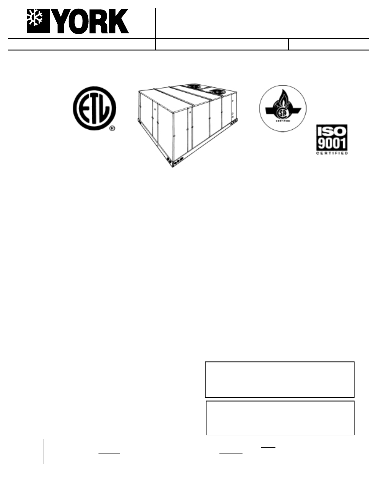
SUNLINE 2000
SINGLE PACKAGE HEAT PUMPS
WITH OR WITHOUT SUPPLEMENTAL ELECTRIC HEAT
INSTALLATION INSTRUCTION
208/230/460 V O LT
MODELS ONLY
SAFETY CONSIDERATIONS
Due to system pressure, moving parts and electrical
components, installation and servicing of air conditioning
equipment can be hazardous. Only qualified, trained, service
personnel should install, repair, maintain or service this
equipment.
Observe al l precautions in the li terature, on labels an d tags
accompanying the equipment whenever working on air
conditioning equipment. Be sure to follow all other safety
precautions that apply.
Wear safety glasses and work gloves, and follow all safety
codes. Use a quenching cloth and have a fire extinguisher
avail able for all braz in g op er ations.
GENERAL
YORK Model BCH units are single package heat pumps
designed for outdoo r ins tall at io n on a ro ofto p or a sl ab. These
units can be eq uipped with f actory in stalle d elec tric heat ers f o r
cooling/heating applications .
The units are completely assembled on rigid, permanently
attached base rails. All pipi ng, refrigeran t charge, a nd electrical
wiring is factory installed and tested. The units require electric
power, duct connections and installation of fixed outdoor air
intake damper (units without economizer or motorized damper
option only) at the point of installation.
The supplemental electric heaters have nickel-chrome
elements and utilize single point power connection.
INSPECTION
As soon as a unit is received, it should be inspected for possible
damage during transit. If damage is evident, the extent of the
damage should be note d on the carrier’ s fre ight bil l. A se parate
request for inspection by the carrier’s agent should be made in
writing. Refer to Form 50.15-NM for additional information.
Supersedes: 511.06-N3Y (1294)
MODELS B1CH180 & 240
(8.5 - 8.8 EER)
REFERENCE
Additional information on the design, installation, operation and
service of this equipmen t is av ailab le in the f ollo wing ref eren ce
forms:
55.70-N1 - General Installation
•
55.70-N2 - Pre-start & Post-start Check List
•
44-320-10 - Barometric Relief Damper Accessory
•
Renewal Parts:
Refer to the Renewal Par ts Manual for comple te listing of
•
replacement parts on this equi pm en t.
All forms referenced in this instruction may be ordered from:
Standard Register
Norman, OK 73069
T oll Free: Tel. 877-318-9675/Fax. 877-379-7920
APPROVALS
Design certified by ETL & CGA as follows:
1. For use as a heat pump only unit or a heat pump with or
without supplemental electric heat.
2. For outdoor installatio n on ly.
3. For installation on co mbustible mate rial.
THIS PRODUCT MUST BE INSTALLED IN STRICT COMPLIANCE
WITH THE ENCLOSED INST ALLA TION INSTR UCTIONS AND ANY
APPLICABLE LOCAL, STATE, AND NATIONAL CODES
INCLUDING, BUT NOT LIMITED TO, BUILDING, ELECTRICAL,
AND MECHANICAL CODES.
INCORRECT INSTALLATION MAY CREATE A CONDITION
WHERE THE OPERATION OF THE PRODUCT COULD CAUSE
PERSONAL INJURY OR PROPERTY DAMAGE
208/230/575 VOLT
MODELS ONLY
CAUTION
WARNING
511.06-N3Y (500)
035-12546-000
Installer should pay particular attention to the words: NOTE, CAUTION and WARNING. Notes are in te nd ed t o cl arify or make
the installa tion ea sier .
and/or equipment damage may result if installation procedure is not handled properly.
Cautions are gi ven t o pre vent equipmen t damage . W arnings are giv en to ale rt installer that personal i njury
Page 2
511.06-N3Y
TABLE OF CONTENTS
General................................................................................ 1
Inspection.............................................................................1
Reference............................................................................. 1
Approvals ............................................................................. 1
Nomenclature.......................................................................2
INSTALLATION
Limitations............................................................................ 3
Location ...............................................................................3
Rigging and Handling .......................................................... 3
Clearances........................................................................... 3
Ductwork .............................................................................. 3
Fixed Outdoor Air Intake Damper........................................ 4
Condensate Drain................................................................4
Compressors........................................................................ 4
Filters ................................................................................... 4
Service Access .................................................................... 4
Thermostat...........................................................................4
Power and Control Wiring.................................................... 4
Optional Electric Heaters......................................... ............ 5
Optional Economizer/Mot. Damper Rain Hood................... 5
Optional Power Exhaust Rain Hood .................................... 7
OPERATION
Cooling System.................................................................. 15
Preliminary Operation Cooling........................................... 15
Cooling Sequence of Op er at io n............... .. .. .. .. ................ ..15
Heating Sequence of Op er at ion ................... .. .. .. .. .............15
Heat Anticipator Setpoints ................................................. 16
Checking Suppl y Air CFM..... .. .. . . .. .. ................ ................ .. .16
Defrost Sequence of Operat ion......................................... 17
Secure Owner’s Approval .................................................. 18
MAINTENANCE
Normal Maintenance ......................................................... 18
TABLES
No. Description Page
1 Unit Applic ation Data .................................. 3
2 Control Wire Sizes ...................................... 5
3 Electric Heat Applica ti on Data.................... 5
4 Physical Data .............................................. 8
5 Four and Six Point Loads............................ 10
6 Supply Air Blower Perf. 15 Ton.................... 12
7 Supply Air Blower Perf. 20 Ton.................... 12
8 Static Resistances ............... ....................... 13
9 Power Exhaust Performance ............. ......... 13
10 Blower Motor and Drive Data...................... 13
11 Electrical Data (Basic Units)....................... 14
12 Electrical Data (Units w/Elec. Heat)............ 14
13 Heat Anticipator Setpoints .......................... 16
FIGURES
No. Description Page
1 Typical Rigging............................................ 3
2 Center of Gra vi ty........... .. .. .. .. .................. .. .. 3
3 Fixed O ut do or Air Dampe r............ .. .. .. ........ 4
4 Recommended Drain Piping....................... 4
5 Typical Field Wiring..................................... 5
6 Adjusting Entha lpy Setpoint.................. .. .... 7
7 Dimensions and Clearances....................... 9
8 Four and Six Point Loads............................ 10
9 Belt Adjus tment ........................................... 16
10 Pressure Drop versus Supply Air CFM...... 16
11 Defrost Initiation Times............................... 17
12 Ambient Modified Time/Temp . Control........ 18
PRODUCT NOMENCLATURE
B 1 C H E C1E
PRODUCT CATEGORY
B = Single Package Heat Pump
(Air Cooled)
PRODUCT GENERATION
1 = 1st Generation
PRODUCT IDENTIFIER
CH = Heat Pump
NOMINAL COOLING
CAPACITY
180 = 15 Tons
240 = 20 Tons
2 Unitary Products Group
FACTORY INSTALLED
0 881 0 2 5
HEAT
A = No Heat
E = Electric
NOMINAL HEATING
CAPACITY
018 = 18 KW
036 = 36 KW
054 = 54 KW
072 = 72 KW
FACTORY INSTALLED
OPTION CODE
EC = Sing. Input Economiz er
DK = Diff. Input Economizer
FD = Sing. Input Economizer
w/Power Exhaust
CF = Diff. Input Economizer
w/Power Exhaust
BG = Motor Outdoor Air
Damper
VOLTAGE CODE
25 = 208/230-3-60
46 = 460-3-60
58 = 575-3-60
Page 3
INSTALLATION
LIMITATIONS
These units must be installed in accordance with the following
national and local safety codes:
In U.S.A.:
1. Nati on al Elec trical Cod e ANSI/ NFPA No. 70.
2. Local electric utility requirements.
In Canada:
1. Current Canadian Electrical Code CSA C22.1.
2. Local electrical code s.
Refer to the Unit Ap plicatio n Data an d to thefor Elec tric Hea t
Application Data table.
If components are to be added to a unit to meet local codes,
they are to be ins talled at the deal er’s and/or the customer’s
expense.
Size of unit for propos ed in st al la tion sh ou ld be ba sed on hea t
loss/heat g ain calcul ation made a ccording to the method s of
the Air Conditioning Contractors of America (ACCA).
TABLE 1
V oltage V ariation,
1
Rated in accordance with ARI Standard 110, utilization range "A".
2
5,000 CFM on 15 ton models with either a 54 or 72 KW heater at 208/230 volts.
LOCATION
Use the following guidelines to sele ct a suitable location for
these units.
1. Unit is designed for outdoor installation only .
2. Outdoor coils must have an unlimited supply of air. Where
3. For ground level installation, use a level concrete slab with
4. Roof structures must be able to support the weight of the
5. Maintain lev el tole rance t o 1/2" m aximum a cross th e entire
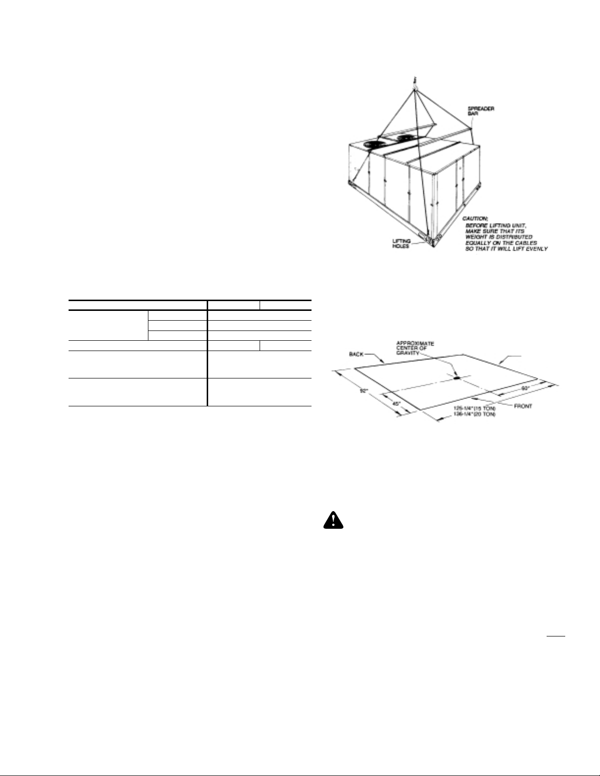
RIGGING AND HANDLING
Exercise care when moving the unit. Do not remove any
packaging until the unit is near the place of installation. Rig the
unit by attaching chain or cable slings to the round lifting holes
provided in t he base rails. Spreaders, wh ose length exceed s
the larger dimension ac ross the unit,
top of the unit. Refer to the Typical Rigging Figure .
- UNIT APPLICATION DATA
Model Size 15 TON 20 T ON
208/230-3-60 187 / 253
Min. / Max.
Supply Air CFM, Min. / Max. 4500
Wet Bulb Temperature (°F)
Dry Bulb Temperature (°F)
1
of Air on Indoor Coil
Min. / Max.
of Air on Outdoor Coil
Min. / Max.
a choice of loca tion is po ssible, positio n the unit on either
north or east side of buildi ng .
a minimum thickness of 4 inches. The length and width
should be at least 6 inches greater than the unit base rail
dimensions. Do not tie slab to the build in g foundation.
unit and its options and/or accessories. Unit must be
installed on a sol id le v el roo f curb or app ropriate angle i ron
frame.
CAUTION: If a unit is to be installed on a roof curb or
special frame other than a YORK roof curb,
gasketing must be applied to a ll surfaces that
come in contact wit h the unit underside.
length or width of the unit.
460-3-60 414 / 506
575-3-60 518 / 630
2
/ 7200 6000 / 9400
57 / 72
45 / 120
be used across t he
MUST
511.06-N3Y
FIG. 1
- TYPICAL RIGGING
Units may also be moved or lifted with a forklift, from the front
or rear only, providing that an accessory skid is used.
LENGTH OF FORKS MUST BE A MINIMUM OF 90".
Refer to the Ph ysical Data t ablef or unit weights a nd to the figure
below for approximate center of gravity.
OUTDOOR
COIL END
FIG. 2
- CENTER OF GRAVITY
CLEARANCES
All units req uire cer tain clearances for prop er operation and
service. Ref er to the Dimensions and Clearances Figure for the
clearances required for combustible construction, servicing,
and proper unit oper at io n.
WARNI NG: Do not permit overhanging structures or shrubs to
obstruct outdoor air di sc ha rge out le t.
DUCTWORK
Ductwork should be designed and sized according to the
methods in Manual Q of the Air Conditioning Contractors of
America (ACCA).
A closed return duct system shall be used. This shall not
preclude u se of ec onomizers or outd oor fres h air inta ke. The
supply and r eturn air duct connections at t he unit should be
made with flexible joints to minimize transmission of noise.
The supply and return air duct systems should be designed for
the CFM and static requirements of the job. They should
be sized to matc h the dime nsions of the duct connect ions on
the unit.
CAUTION: When fastening ductwork to side duct flanges on
the unit, in sert screws throug h duct flanges only.
DO NOT insert screws through casing.
Outdoor ductwork must be insulated and
waterproofed.
Refer to the Dimensions and Clearances Figure for information
concerning side and bottom supply and return air duct openings.
NOT
Unitary Products Group 3
Page 4
511.06-N3Y
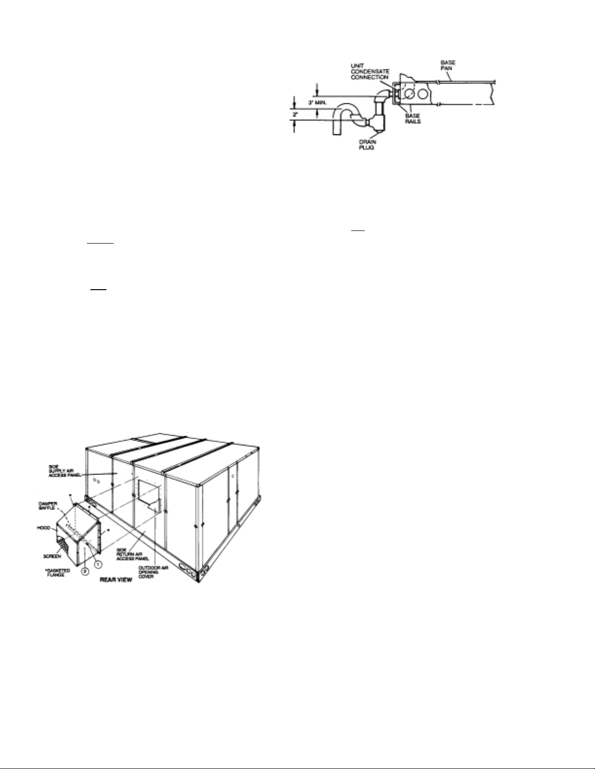
FIXED OUTDOOR AIR INTAKE DAMPER
This damper is shipped inside the return air compartment. It is
completely assembled and ready for installation. A damper
baffle inside the hood is adjustable to provide variable
amounts of outdoor air intake on units that are not provided
with an economizer or a motorized damper option.
Gasketing and mounting screws are provided in a parts bag
attached to the hood assembly. Apply gasketing to the three
flange surfaces on the hood prior to installing the hood. Extend
gasketing 1/4" beyond the top and bottom of the two side
flanges to insure adequate sealing.
FIG. 4 -
RECOMMENDED DRAIN PIPING
Adjusting the damper to the desired air flow may be done before
mounting the hood into position or (after installation) by
removing the front hood panel or the screen on the bottom of
the hood. Damper baffle in po sition 1 will allow appr oximatel y
10% recirculated air f low , pos ition 2 appro ximatel y 15% and, to
allow approximately 25%, remove the damper baffle.
On units with
assembly o v er the o peni ng in the side retu rn air a ccess pane l.
Remove and discard the opening cover and the covering over
the hood moun ti ng h ol es (u se d for ship pi ng) be fore inst al li ng.
Secure with the screws provided.
On units with side return air ap plications, install the damper
assembly on th e return air duc twork as close to the unit as
possible. Cut an opening 16" high by 18" wide in the ductwork
to accommodate the damper. Using the holes in the hood
flanges as a template, drill 9/64" dia. (#26 drill) holes into the
ductwork and secu re with the screws provi de d.
CAUTION: If outdoor air intake will not be required on units
bottom return air appl icat ions , i nstall the d ampe r
with bottom return air applications, the damper
assembly s hould still be moun ted on the side return
air access panel, per the instructions above, to
insure mois ture is not drawn into the unit du ring
operation. The covering over the mounting holes
only need be removed. Do not remove the opening
cover.
COMPRESSORS
Units are ship ped with compres sor mountings facto ry-adjusted
and ready for operation.
CAUTION: Do Not loosen compressor mounting bol ts.
FILTERS
2" filters are supplied wi th each unit. Filters must a lways be
installed ahead of the indoor coil and must be kept clean or
replaced wi th sam e size and typ e. Dirty fi lters will re duce th e
capacity of the unit and will result in frosted coils or safety
shutdown. Minimum filter area and re quired siz es are s hown in
the Physical Data table.
SERVICE ACCESS
Access to all serviceable components is provided by the
follo w in g rem o vable panels:
Compressor compartment
•
Electri c Heat compartment
•
Side Supply & Return Air compartments (Two panels)
•
Blower compartment (Three panels)
•
Main control box
•
Filter compartment
•
Outdoor Air compartment (Two panels)
•
Refer to Dimensions and Clearnaces Fig ure for locati on of
these access panels.
CAUTION: Make sure that all screws and panel latches are
replaced and properly positioned on the unit to
maintain an air-ti gh t se al .
THERMOSTAT
The room thermostat should be located on an inside wall
approximately 56" above the floor where it will not be subject
to drafts, sun exposure or heat from electrical fixtures or
appliances. Follow manufacturer’s instructions enclosed with
thermostat for general installation procedure. Color coded
insulated wires (#18 AWG) should be used to connect
thermostat to unit. Eight conducto rs are requ ire d.
The subbase on the low voltage thermostat includes an
"Emergency H eat" position on the system switch and a pilot
light. In the "Emergency Heat" position, the thermostat will
provide elect ric resist ance he at on ly. Th e com press ors wil l not
run. The pilot light wi ll indi cate th at the switc h is on "E M HT".
FIG. 3
- FIXED OUTDOOR AIR DAMPER
CONDENSATE DRAIN
Plumbing must conform to local codes. Use a sealing
compound on male pipe threads. Install a condensate drain line
from the 1" NPT f emale connectio n on the unit to an op en drain.
An alternate drain connection (1" NPT female coupling) is
provided inboard on the same centerline as the exterior
location.
NOTE: The condensate drain operates in a negative pressure
4 Unitary Products Group
in the cabi net. The conden sate drain line MUST be
trapped to provide proper drainage.
Nine conductors are required for this application.
POWER AND CONTR OL WIRING
Field wiring to the unit must conform to provisions of the
National Electrical Code, ANSI / NFPA No. 70 (in U.S.A.),
current Canadian Electric Code (CEC) CSA C22.1 (in Canada)
and/or local ord inances. The unit must be electrically g rounded
in accordance with NEC and C EC (as spec if ied ab ove) and/or
local codes. Voltage tolerances which must be maintained at
the compressor terminals during starting and running
conditions are in di ca ted on the unit Rating Plate.
Page 5
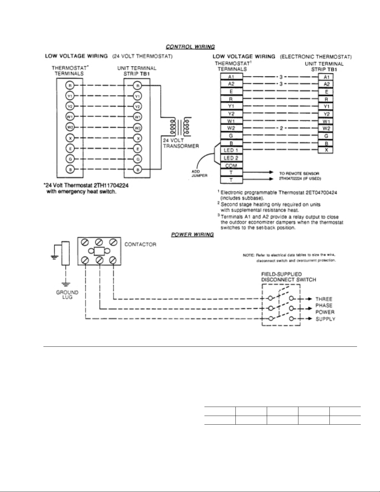
511.06-N3Y
FIG. 5
- TYPICAL FIELD WIRING
The internal wiring harness furnished with this unit is an integral
part of a ETL and CGA design certified unit. Field alteratio n to
comply with electrical codes should not be required.
MUST BE USED so that water or moisture cannot
be drawn into the unit during normal operat ion. The
above waterproofing conditions will also apply
when installing a field-supplied disconnect switch.
A fused disconnect switch should be field provided for the unit.
The switch must be separate from all other circuits. Wire entry
at knockout openings require conduit fittings to comply with
CEC (in Canada), NEC (in U.S.A.) and/or local codes. Refer to
TABLE 2 -
the Dimensions and Clearances Figure for installation location.
If any of the wire supplied with the unit must be replaced,
replacement wire must be of the type shown on the wiring
diagram and the same minimum gauge as the replaced wire.
Electric al line must be sized proper ly to carr y the load . Each
unit must be wired with a separate branch circuit fed directly
from the meter panel and properly fused.
CAUTION: When connecting electrical power and control
wiring to the unit, waterproof type connectors
Unitary Products Group 5
Notes:
1. Solid, Class II copper wire
2. Based on a voltage drop of 1.2 volt s per wir e .
3. Total wire length is from unit to room thermostat, and back to unit
CONTROL WIRE SIZES
Wire Size1 AWG. Gauge
22 20 19 18 16
40 120 150 190 305
Maximum Wire Length
2
Feet
Page 6

511.06-N3Y
Refer to th e Typical Field Wiring Fi gure and to the app ropriate
unit wiring diagram for control circuit and power wiring
information.
all the control sensors are factory mounted as part of the
"Fac to ry install ed " economizer option.
ENTHALPY SET POINT ADJUSTMENT
OPTIONAL ELECTRIC HEATERS
The factory installed heaters are wired for single point power
supply. P ower suppl y need only be brou ght into the s ingle point
terminal block and thermostat w iring to the lo w volta ge terminal
strip located in the upper portion of the unit control box.
These ETL an d CGA a pp roved he ater s ar e loca te d w ithi n th e
central compartment of the unit with the heater elements
extending into the supply air chamber. Refer to the Dimensions
and Clearances Figure for access panel location.
TABLE 3
HEATER SIZE
- ELECTRIC HEAT APPLICATION DATA
NOMINAL
(KW)
18 208/230,460,575 4500 6000
36 208/230,460,575 4500 6000
54
72
VOLT AGE
3 PHASE,
60 HZ
208/230 5000
460, 575 4500
208/230 5000
460, 575 4500
MINIMUM CFM
(UNIT SIZE)
15 TON 20 TON
6000
6000
Fuses are supplied, where required, by the factory. Some KW sizes
require fuses and others do not. Refer to the Electric Heat Application
table for minimum CFM limitations and to the Electrical Data table for
electrical data.
OPTIONAL ECONOMIZER/MOTORIZED DAMPER
RAIN HOOD
The instru ction for the optional econ omizer/motorized damper
rain hood can be found in form 44-320-2. Use these instructions
when field a ssembling an econom izer rain hood onto a un it.
The outdoor and return air damp ers, the damper actuator, the
damper linkage, the outdoor and return air divider baffles, and
Remove the economizer access panel from the unit to check
the following adjustments. Loosen but do not remove the two
panel latches.
CAUTION: Extreme care must be exercised in turning both
the setpoint and minimum position adjusting
screws to prevent twist i ng them off.
1. T he enthalpy set point may now be set by selecting the
desired setpoint shown in the Adj us ti ng En thalpy Setpoi nt
Figure. Adjust as follows:
For a single en thalpy operation, carefully turn the set
•
point adjusting screw to the “A”, “B”, “C” or “D” setting
corresponding t o th e le tt ere d cu rve .
For a dual enthalpy operation, carefully turn the set point
•
adjusting screw fully clockwise past the “D” setting.
2. To check that the damper blades move smoothly without
binding, carefully turn the minimum position adjusting
screw fully cl ockwise and then energize and de -energize
terminals “R” to “G”. With terminals “R” to “G” energized,
turn the minimum position screw counterclockwise until the
desired minimum position has been attained.
3. Replace the economizer access panel. Reposition the two
latches horizontally and retighten the screws.
POWER EXHAUST/BAROMETRIC RELIEF DAMPER
AND RAIN HOOD OPTION
The instructions for the power exhaust/barometric relief
damper and ra in hood can be found in form 44-320-10. The
exhaust fan, all supporting brackets, angles, and the wiring are
factory installed as part of the power exhaust option.
All of the components, including the dampers, hardware, and
mounting inst ructions are shipp ed in a single p ackag e e xternal
from the unit. The hood must be fie ld assem bled and inst alled.
Power exhaust is not available as a field installed option.
6 Unitary Products Group
Page 7

511.06-N3Y
FIG. 6
- ENTHALPY SETPOINT ADJUSTMENT
Unitary Products Group 7
Page 8

511.06-N3Y
TABLE 4
SUPPLY AIR
OUTDOOR
(Two Per Unit)
OUTDOOR
COMPRESSOR
(Qty. Per Unit)
- PHYSICAL DATA
BLOWER
INDOOR
COIL
FANS
COILS
AIR
FIL TERS
CHARGE
MODELS
CENTRIFUGAL BLOWER (Dia. x Wd. in.) 15 x 15 18 x 15
FAN MOTOR HP 5 7.5
ROWS DEEP 4 4
FINS PER INCH 13 13
FACE AREA (Sq. Ft.) 15.5 20.5
PROPELLER DIA. (in.) (Each) 30 30
FAN MOTOR HP (Each) 1 1
NOM. CFM TOTAL (Each) 6500 7200
ROWS DEEP 3 3
FINS PER INCH 15 15
FACE AREA (Sq. Ft.) 36.0 43.3
7-1/2 TON TANDEM 2 10 TON TANDEM - 2
QUANTITY PER UNIT (16" X 20" X 2") - 4
QUANTITY PER UNIT (16" X 25" X 2") - 4
QUANTITY PER UNIT (18" X 24" X 2") 5 TOTAL FACE AREA (sq. ft.) 15.0 20.0
REFRIGERANT 22
(lbs./oz.)
SYSTEM NO. 1 20/8 24/0
SYSTEM NO. 2 22/8 25/0
UNIT SIZE
15 TON 20 TON
OPERATING WEIGHTS (LBS.) 15 TON 20 TON
Basic Unit Heat Pump 2000 2200
Economizer 160
Options
Accessories
Economizer with
Power E xhaust
Motorized Damper 150
18 KW 25
Electric Heat
(Nominal KW)
Roof Curb 175 185
Barometric Damper 45 45
Wood Skid 200 220
36 KW 30
54 KW 35
72 KW 40
245
8 Unitary Products Group
Page 9

RETURN AIR
SUPPLY AIR
OUTDOOR AIR
OUTDOOR AIR
(Economizer)
All dimensions are in inches. They are subject to change without notice. Certified dimensions will be provided upon request.
UTILITIES ENTRY DATA
HOLE
A
B
OPENING
SIZE
USED FOR
(DIA.)
1-1/8" KO
3/4" NPS (Fem.) Bottom
3-5/8" KO
3" NPS (Fem.) Bottom
Control
Wiring
Power
Wiring
511.06-N3Y
Front
Front
DUCT COVERS - Units are shipped with the bottom
duct openings covered. An accessory flange kit is available for connecting side ducts.
For
bottom duct applications:
1. Remov e the side panels from the supply and return
air compartments to gain access to the bottom
supply and return air duct covers.
2. Remove and discard the bottom duct covers. (Duct
openings are closed with sheet metal covers except
when the unit includes a power exhaust option. The
covering consists of a heavy black paper composition.)
3. Replace the side supply and return air compartment
panels.
For
side duct applications;
1. Replace the side panels on the supply and return air
compartments with the accessory flange kit panels.
2. Connect ductwork to the duct flanges on the rear of
the unit.
OUTDOOR SECTION
(ACCESSORY SIDE SUPPLY AND RETURN AIR OPENINGS)
DETAIL "X"
FIG. 7
- DIMENSIONS & CLEARANCES - 15 & 20 TON
INDOOR SECTION
CLEARANCES
Front 36"
Back
Left Side (Filter Access)
Right Side (Cond. Coil) 36"
Below Unit
Above Unit
NOTE: Unit and ductwork are approved for zero clearance to combustible
materials when equipped with electric heat.
1
Units (applicable in U.S . A. only) may be installed on combustib le floors made
from wood or class A, B or C roof covering material.
2
Units must be installed oudo ors. Overhanging structures or shrubs should
not obstruct outdoor air disc h arge outlet.
3
If economizer is factory installed, the assembled hood kit must be removed
prior to final installation. This hood is 54" long.
4
Remove hood kit prior to final installation.
1
2
24" (Less Economizer)
49" (With Economizer)
24" (Less Economizer)
3
36"
(With Economizer)
20"
72" With 36" Maximum
Horizontal Overhang
(For Outdoor Air
Discharge Outlet)
4
Unitary Products Group 9
Page 10

511.06-N3Y
B
A
D
FIG. 8
- FOUR AND SIX POINT LOADS
TABLE 5
- FOUR AND SIX POINT LOADS
UNIT
FRONT
4 POINT LOADS
TOT AL A B C D
C
180 2,190 513 535 583 559
240 2,390 514 538 684 654
NOTE: These weights are with ec on om izer and 36kW electric heat.
UNIT
TOT AL A B C D E F
180 2,190 342 358 373 388 372 357
240 2,390 343 359 407 456 436 389
6 - POINT LOADS (LBS)
A
4 - POINT LOADS (LBS)
E
F
D
C
FRONT
B
6 POINT LOADS
NOTE: These weights are with ec on om izer and 36kW electric heat.
10 Unitary Products Group
Page 11

TABLE 6
511.06-N3Y
- SUPPLY AIR BLOWER PERFORMANCE (1 5 TON)
180 MBH
BLOWER
SPEED,
(RPM)
- BOTTOM DUCT CONNECTIONS
MOTOR
PULLEY
(TURNS
OPEN)*
4500 5250 6000 6750 7200
ESP BHP KW ESP BHP KW ESP BHP KW ESP BHP KW ESP BHP KW
CFM
208 VOLT AND STANDARD DRIVE
850 6.0** 0.9 2.4 2.2 0.7 3.0 2.7 0.5 3.2 2.9 - - - - - 870 5.5 1.0 2.5 2.3 0.8 3.1 2.8 0.6 3.5 3.1 0.2 4.1 3.7 - - 915 4.5 1.1 2.6 2.4 0.9 3.4 3.0 0.7 3.7 3.3 0.3 4.4 3.9 0.2 4.5 4.0
965 3.5 1.2 2.9 2.6 1.0 3.6 3.2 0.8 4.0 3.6 0.5 4.7 4.2 0.4 4.9 4.4
980 3.0 1.3 3.0 2.7 1.1 3.7 3.3 0.9 4.1 3.7 0.6 4.8 4.3 0.5 5.1 4.6
1010 2.0 1.4 3.1 2.8 1.2 3.8 3.4 1.0 4.2 3.8 0.7 5.0 4.5 0.6 5.4 4.8
1040 1.0 1.5 3.2 2.9 1.3 3.9 3.5 1.1 4.5 4.0 0.9 5.2 4.7 0.7 5.7 5.1
208 VOLT AND HIGH SPEED DRIVE ACCESSOR Y
965 6.0 1.2 2.9 2.6 1.0 3.6 3.2 0.8 4.0 3.6 0.5 4.7 4.2 0.4 5.0 4.4
980 5.5 1.3 3.0 2.7 1.1 3.7 3.3 0.9 4.1 3.7 0.6 4.8 4.3 0.5 5.1 4.6
1025 4.5 1.5 3.2 2.9 1.3 3.9 3.5 1.1 4.5 4.0 0.8 5.1 4.6 0.7 5.6 5.0
1065 3.5 1.6 3.4 3.0 1.4 4.0 3.6 1.2 4.7 4.2 1.0 5.5 4.9 - - 1095 3.0 1.7 3.5 3.1 1.5 4.2 3.8 1.3 4.9 4.4 1.2 5.7 5.1 - - 1130 2.0 1.9 3.7 3.3 1.7 4.5 4.0 1.5 5.1 4.6 - - - - - 1170 1.0 2.1 3.9 3.5 2.0 4.7 4.2 1.8 5.5 4.9 - - - - - -
230/460/575 V OLT AND ST ANDARD DRIVE
870 6.0** 1.0 2.4 2.2 0.8 3.1 2.8 0.6 3.5 3.1 0.2 4.1 3.7 - - -
915 5.0 1.1 2.6 2.4 0.9 3.3 3.0 0.7 3.7 3.3 0.3 4.4 3.9 0.2 4.5 4.0
965 4.0 1.2 2.9 2.6 1.0 3.6 3.2 0.8 4.0 3.6 0.5 4.7 4.2 0.4 5.0 4.4
980 3.5 1.3 3.0 2.7 1.1 3.7 3.3 0.9 4.1 3.7 0.6 4.8 4.3 0.5 5.1 4.6
1040 2.0 1.5 3.2 2.9 1.3 3.9 3.5 1.1 4.5 4.0 0.9 5.3 4.7 0.7 5.7 5.1
1065 1.0 1.6 3.3 3.0 1.4 4.0 3.6 1.2 4.7 4.2 1.0 5.5 4.9 - - -
230/460/575 V OLT AND HIGH SPEED DRIVE ACCESSOR Y
980 6.0 1.3 2.9 2.6 1.1 3.7 3.3 0.9 4.1 3.7 0.6 4.8 4.3 0.5 5.1 4.6
1040 4.5 1.5 3.2 2.9 1.3 3.9 3.5 1.1 4.5 4.0 0.9 5.3 4.7 0.7 5.7 5.1
1065 4.0 1.6 3.4 3.0 1.4 4.0 3.6 1.2 4.7 4.2 1.0 5.5 4.9 - - 1095 3.5 1.7 3.5 3.1 1.5 4.2 3.8 1.3 4.9 4.4 1.2 5.7 5.1 - - 1130 2.5 1.9 3.7 3.3 1.7 4.5 4.0 1.5 5.1 4.6 - - - - - 1170 1.5 2.1 3.9 3.5 2.0 4.7 4.2 1.8 5.5 4.9 - - - - - 1190 1.0 2.2 4.0 3.6 2.1 4.8 4.3 2.0 5.7 5.1 - - - - - -
NOTES: 1. Blower performance includes fixed outdoor air, 2" T/A filters, a dry indoor coil and no electric heat.
2. Refer to Page 12 for additional static resistances.
ESP = External Static Pressure available for the supply and return air duct system. All internal unit resistances have been deducted
from the total static pressure of the blower.
* Do
NOT close the pulley below 1 turn open.
** Factory setting.
Unitary Products Group 11
Page 12

511.06-N3Y
TABLE 7
- SUPPLY AIR BLOWER PERFORMANCE (20 TON)
240 MBH
BLOWER
SPEED,
(RPM)
- BOTTOM DUCT CONNECTIONS
MOTOR
PULLEY
(TURNS
OPEN)*
6000 7000 8000 9000 9400
ESP BHP KW ESP BHP KW ESP BHP KW ESP BHP KW ESP BHP KW
CFM
208 VOLT AND STANDARD DRIVE
870 6.0**0.42.11.80.12.32.0--------900 5.00.83.22.70.53.52.90.23.83.2-----930 4.0 1.1 4.1 3.4 0.9 4.5 3.8 0.6 4.9 4.1 0.1 5.1 4.3 - - 950 3.0 1.3 4.6 3.9 1.1 5.1 4.3 0.8 5.5 4.6 0.4 5.9 5.0 - - 980 2.0 1.6 5.3 4.5 1.4 5.8 4.9 1.2 6.3 5.3 0.7 6.9 5.8 0.2 7.3 6.1
1015 1.0 1.9 5.9 5.0 1.7 6.5 5.5 1.5 7.0 5.9 1.0 7.7 6.5 0.6 8.2 6.9
208 VOLT AND HIGH SPEED DRIVE ACCESSOR Y
950 6.0 1.3 4.6 3.9 1.1 5.1 4.3 0.8 5.5 4.6 0.4 5.9 5.0 - - -
980 5.0 1.6 5.3 4.5 1.4 5.8 4.9 1.2 6.3 5.3 0.7 6.9 5.8 0.2 7.3 6.1
1010 4.0 1.8 5.8 4.9 1.7 6.3 5.3 1.5 6.9 5.8 1.0 7.5 6.3 0.5 7.9 6.7
1020 3.5 1.9 6.1 5.1 1.8 6.5 5.5 1.6 7.1 6.0 1.1 7.8 6.6 0.6 8.3 7.0
1035 3.0 2.0 6.2 5.2 1.9 6.8 5.7 1.7 7.4 6.2 1.2 8.1 6.8 0.7 8.6 7.3
1050 2.5 2.1 6.4 5.4 2.0 7.0 5.9 1.8 7.6 6.4 1.3 8.3 7.0 - - 1075 2.0 2.3 6.6 5.5 2.1 7.2 6.0 1.9 7.8 6.6 1.5 8.6 7.2 - - 1100 1.0 2.4 6.7 5.6 2.2 7.3 6.1 2.1 7.9 6.7 ------
230/460/575 V OLT AND STANDARD DRIVE
870 6.0**0.42.11.80.12.32.0---------
900 5.00.83.22.70.53.52.90.23.83.2------
930 4.0 1.1 4.1 3.4 0.9 4.5 3.8 0.6 4.9 4.1 0.1 5.1 4.3 - - -
950 3.5 1.3 4.6 3.9 1.1 5.1 4.3 0.8 5.5 4.6 0.4 5.9 5.0 - - -
980 2.5 1.6 5.3 4.5 1.4 5.8 4.9 1.2 6.3 5.3 0.7 6.9 5.8 0.2 7.3 6.1
1015 1.5 1.9 5.9 5.0 1.7 6.5 5.5 1.5 7.0 5.9 1.0 7.7 6.5 0.6 8.2 6.9
1025 1.0 2.0 6.1 5.1 1.8 6.6 5.6 1.6 7.3 6.1 1.1 7.9 6.7 0.7 8.6 7.3
230/460/575 VOLT AND HIGH SPEED DRIVE ACCESSOR Y
950 6.0 1.3 4.6 3.9 1.1 5.1 4.3 0.8 5.5 4.6 0.4 5.9 5.0 - - -
980 5.0 1.6 5.3 4.5 1.4 5.8 4.9 1.2 6.3 5.3 0.7 6.9 5.8 0.2 7.3 6.1
1015 4.0 1.9 5.9 5.0 1.7 6.5 5.5 1.5 7.0 5.9 1.0 7.7 6.5 0.6 8.2 6.9
1035 3.5 2.0 6.2 5.2 1.9 6.8 5.7 1.7 7.4 6.2 1.2 8.1 6.8 0.7 8.6 7.3
1050 3.0 2.1 6.4 5.4 2.0 7.0 5.9 1.8 7.6 6.4 1.3 8.3 7.0 - - 1080 2.0 2.3 6.6 5.5 2.1 7.2 6.0 1.9 7.8 6.6 1.5 8.6 7.2 - - 1100 1.5 2.4 6.7 5.6 2.2 7.3 6.1 2.1 7.9 6.7 -----1120 1.0 2.5 6.8 5.7 2.3 7.4 6.2 2.2 8.1 6.8 ------
NOTES: 1. Blower performance includes fixed outdoor air, 2" T/A filters, a dry indoor coil and no electric heat.
2. Refer to Page 12 for additional static resistances.
ESP = External Static Pressure available for the supply and return air duct system. All internal unit resistances have been deducted
from the total static pressure of the blower.
* Do
NOT close the pulley below 1 turn open.
** Factory setting.
12 Unitary Products Group
Page 13

511.06-N3Y
TABLE 8
TABLE 9
- STATIC RESISTANCES
1
EXTERNAL STATIC PRESSURE DROP
RESISTANCE, IWG
DESCRIPTION
15 TON 20 TON
CFM
4500 6000 7200 6000 8000 9400
WET INDOOR COIL 0.1 0.1 0.1 0.1 0.1 0.1
18 KW 0.1 0.1 0.1 0.1 0.1 0.1
ELECTRIC HEAT OPTIONS
36 KW 0.1 0.2 0.3 0.1 0.2 0.3
54 KW 0.2 0.3 0.4 0.2 0.3 0.4
72 KW 0.2 0.4 0.6 0.2 0.4 0.6
ECONOMIZER OPTION 0.1 0.1 0.1 0.1 0.1 0.1
HORIZONTAL DUCT CONNECTIONS
1
Deduct these resistance values from the available external stati c pressures shown in the respective Blower Performance Table. (See Note 2 f o r exception.)
2
Since the resistance to air flow will be less for horizontal duct connections than for bottom duct connections, add these pressures to the ESP values on the
respective unit’s blower performance table.
2
0.2 0.3 0.5 0.2 0.3 0.5
- POWER EXHAUST PERFORMANCE
MOTOR
SPEED
0.2 0.3 0.4 0.5 0.6
CFM KW CFM KW CFM KW CFM KW CFM KW
HIGH* 5250 0.83 4500 0.85 4200 0.88 3750 0.93 3000 0.99
STATIC RESISTANCE OF RETURN DUCTWORK, IWG
MEDIUM 4900 0.77 3900 0.79 3500 0.82 2900 0.85 - -
LOW 4400 0.72 3700 0.74 3000 0.78 - - - -
Factory Setting
*
Power Exhaust motor is a 3/4 HP, PSC type with sleeve bearings, a 48 frame and inherent protection.
TABLE 10
MODEL
SIZE
15 TON
- BLOWER MOTOR AND DRIVE DATA
1
BLOWER
DRIVE
RANGE
(RPM)
Stan-
850/1065
dard
High
Speed
965/1190 BK80 7.75 7.4 1 BX68 69.8 1
MOTOR
HP FRAME
5 184T 83 1VP56 5.35
ADJUSTABLE MOTOR PULLEY FIXED BLOWER PULLEY
EFF.
(%)
DESIG-
NATION
OUTSIDE
DIA.
(IN.)
PITCH
DIA.
(IN.)
BORE
(IN.)
DESIG-
NATION
OUTSIDE
DIA.
(IN.)
BK90 8.75 8.4 1 BX70 71.8 1
4.3-
1-1/8
2
5.3
PITCH
DIA.
(IN.)
BORE
(IN.)
DESIG-
NATION
BELT
(NOTCHED)
PITCH
LENGTH
(IN.)
Access
Stan-
870/1025
20 TON
1
All motors have a nominal speed of 1800 RPM, a 1.15 service factor and a solid base. They can operate to the limit of their service factor because they are located in the moving air, upstream
of any heating device.
2
Do NOT close this pulley below 1 turn open.
High
Speed
950/1120 BK110 10.75 10.4 1-3/16 BX80 81.8 1
Access
7.5 213T 89 1VP68 6.75
dard
5.5-
6.5
2
BK120 11.75 11.4 1-3/16 BX83 84.8 1
1-3/8
QTY.
Unitary Products Group 13
Page 14

511.06-N3Y
TABLE 11
- ELECTRICAL DATA (BASIC UNITS)
COMPRESSORS OUTDOOR FAN
MODEL
POWER
SUPPLY
#1 #2
RLA LRA RLA LRA
MOTORS
(#1 & #2)
HP
EACH
208/230-3-60 28.2 260 28.2 260 1 4.1/4.2 5 14.4/15.4 86.1/87.3 110
B1CH180
460-3-60 14.1 128 14.1 128 1 2.1 5 7.2 43.1 50
575-3-60 11.5 104 11.5 104 1 2.0 5 5.9 35.9 45
208/230-3-60 33.3 300 33.3 300 1 4.1/4.2 7.5 19.4/21.0 102.6/104.4 125
B1CH240
460-3-60 19.2 146 19.2 146 1 2.1 7.5 9.7 57.2 70
575-3-60 12.8 124 12.8 124 1 2.0 7.5 7.8 40.6 50
Although these sizes are based on copper conductors, aluminum wire can be used.
*
Refer to the National Electric Code ( in U.S.A.) or the current Canadian Electrical Code
(in Canada) to determine the proper size.
TABLE 12
- ELECTRICAL DATA
(UNITS w/SUPPLEMENTAL ELECTRIC HEAT)
HEATER OPTION MINIMUM
MODEL
B1CH
180A25
180A46 460-3-60
180A58 575-3-60
240A25
240A46 460-3-60
240A58 575-3-60
1
Electric Heat CORRECTION FACTORS:
NOMINAL VOLTAGE VOLTAGE KW CAP. MULTIPLIER
208 208 1.00
240 230 0.92
480 460 0.92
600 575 0.92
POWER
SUPPLY
208-3-60
230-3-60
208-3-60
230-3-60
MODEL KW
E018
E036
E054
E072
E018
E036
E054
E072
E018
E036
E054
E072
E018
E036
E054
E072
E018
E036
E054
E072
E018
E036
E054
E072
E018
E036
E054
E072
E018
E036
E054
E072
13.5
27.0
40.6
54.1
18.0
36.0
54.0
72.0
18.0
36.0
54.0
72.0
18.0
36.0
54.0
72.0
13.5
27.0
40.6
54.1
18.0
36.0
54.0
72.0
18.0
36.0
54.0
72.0
18.0
36.0
54.0
72.0
1
FLA
EACH
SUPPLY AIR
BLOWER
MOTOR
HP FLA
VOLT AGE
LIMITATIONS**
**
Rated in accordance with ARI Standard 110, utilization rang e "A".
MINIMUM
CIRCUIT
AMPACITY
(AMPS)
POWER SUPPLY
208/230-3-60 187 253
460-3-60 414 506
575-3-60 518 630
MAXIMUM
TIME DELAY
FUSE SIZE
(AMPS)
MIN. MAX.
CIRCUIT
STAGES AMPS
1
2
2
2
1
2
2
2
1
2
2
2
1
2
2
2
1
2
2
2
1
2
2
2
1
2
2
2
1
2
2
2
2
Although these sizes are based on copper conductors, aluminum wire can be used.
Refer to the National Electric code ( in U.S.A.) or the current Canadian Electrical Code
(in Canada) to determin e th e pr op er size.
37.5
75.1
112.6
150.1
43.3
86.6
129.9
173.2
21.7
43.3
65.0
86.6
17.3
34.6
52.0
69.3
37.5
75.1
112.6
150.1
43.3
86.6
129.9
173.2
21.7
43.3
65.0
86.6
17.3
34.6
52.0
69.3
AMPACITY
(AMPS)
133.0
133.0
179.9
179.9
141.4
141.4
195.5
195.5
70.2
70.2
97.3
97.3
57.5
57.5
79.2
79.2
149.5
149.5
196.4
212.7
158.5
158.5
196.4
212.7
84.2
84.2
111.3
111.3
62.3
62.3
83.9
83.9
VOLT AGE
MAXIMUM
TIME DELAY
FUSE SIZE
(AMPS)
150
150
200
200
150
150
200
200
80
80
100
100
60
60
80
80
150
150
200
225
175
175
200
225
90
90
125
125
70
70
90
90
14 Unitary Products Group
Page 15

OPERATION
511.06-N3Y
COOLING SYSTEM
The unit has an air-cooled cooling section and is
factory-charged with Refr igerant-22.
The compresso rs are hermetically sealed, internally sp rung
and base-mounted with rubber-insulated hold-down bolts.
Compressors have inherent (internal) protection. If there is an
abnormal temperature rise in a compressor, the protector will
open to shut down the compressor.
PRELIMINARY OPERATION COOLING
After installation has been completed, energize the crankcase
heaters for at least four hours before operatin g the unit. After
the initial installation, the compressors should be given three
false starts (energized just long enough to make a few
revolutions) with 5-7 minutes delay between each start, before
being put into ful l ti me service.
NOTE: Prior to each cool ing season , the crankcas e heaters
must be energized at le ast 8 hours before system is
put into operation.
COOLING SEQUENCE OF OPERATION
NO OUTDOOR AIR OPTIONS - When the room ther mostat
calls fo r "first-stage" coo ling, the lo w voltag e control circuit f rom
"R" to "G" and "Y1" is completed to energize compressor #1,
outdoor fan motor #1, outdoor fan motor #2 (if the ambient
temperature is abov e 60°F), and the supp ly air b lower motor (if
the fan switch on the room thermostat is set in the "AUTO"
position).
When the thermostat calls for "second-stage" cooling, the low
voltage co ntrol circuit fro m "R" to "Y2" is complete d to energiz e
compressor #2.
After the thermostat is satisfied and opens, all components will
stop simultaneously . The blower motor will continue to operate
if the fan switch on t he room thermostat i s set in the "ON"
position.
The rev ersi ng v a lv e i s ene rgiz ed t hru the " Y1" circu it whe n the
subbase is in the cooling mode.
setpoint, "Y1" energiz es compresso r #1, out door f an motor # 1,
and outdoor fan motor #2 (if the ambient temperature is above
60°F).
When the thermostat calls for "second-stage" cooling, the low
voltage control circuit from "R" to "Y2" is completed. If the
enthalp y of the outdoor ai r is below t he setpoi nt of the e nthalp y
controller (i.e. first stage has energized the economizer), "Y2"
will energize compressor #1. If the outdoor air is above the
setpoint, "Y2" wil l energize compressor #2.
After the thermostat is satisfied and opens, all components will
stop simultaneously . The blower motor will continue to operate
if the fan switch on t he room thermostat i s set in the "ON"
position.
ECONOMIZER WITH DUAL ENTHALPY SENSORS - The
operation with the dual enthalpy sensors is identical to the
single sensor e xcept that a second ent halpy se nsor is mounted
in the retur n air. This return air sensor allows the econ omizer
to choose between outdoor air and return air, whichever has
the lowest enthalpy value, to provide maximum operating
efficiency.
ECONOMIZER (SINGLE OR DUAL) WITH POWER
EXHAUST - Thi s system op erates as specifie d abov e with o ne
addition. The power exhaust motor is energized whenever the
economizer is chosen by the enthalpy sensor for first stage
cooling, "Y1 ". As always, the "R" to "G" connection provides
minimum position but does not provide power exhaust
operation.
MOTORIZED OUTDOOR AIR DAMPERS - This system
operation i s th e sa me a s th e un it s wi th no ou tdoo r ai r op ti on s
with one exception. When the "R" to "G" circuit is complete, the
motorized damper drives open to a position set by the
thumbwheel on the damper motor. When the "R" to "G" circuit
is opened, the damper spring returns fully closed.
HEATING SEQUENCE OF OPERATION
The following sequence of operation is based on using a
standard heat pump two-stage heating/two-stage cooling
thermostat/subbase. Economizer (if supplied) operation is not
allowed in the heatin g mode - however the minimum p ositio n
does operate.
The suction lin e fre ezesta t will cut th e comp res sors ou t when
the suction line temperature drops below 26°F. This is and
automatic reset device.
ECONOMIZER WITH SINGLE ENTHALPY SENSOR - When
the room thermostat calls for "first-stage" cooling, the low
voltage control circuit from "R" to "G" and "Y1" is completed.
The "R" to "G" circuit energizes the blower motor (if the fan
switch on the ro om ther mostat is set in the " AUTO" position)
and drives the economizer dampers from fully closed to their
minimum positi on. If the enthalp y of the ou tdoor air is be low the
setpoint of th e enthalpy cont roller (previous ly determined), "Y1"
energizes the economizer. The dampers will modulate to
maintain a constant supply air temperature as monitored by the
discharge air sensor. If the outdoor air enthalpy is above the
Unitary Products Group 15
FIRST STAGE HEAT
When the thermostat call s for “heat ing”, the low voltag e control
circuit from “R” to “G” and “W1" (wiring sc hematic) is com pleted
to energize the compressors, outdoor fan motors and blower
motor (if subbase is set on auto) simultaneously . If the subbase
has the indoor f an set on ”on " the mo tor will run all of th e tim e.
SECOND STAGE HEAT
If the compressors alone can not satisfy the heating
requirement s, second st age heat wi ll energize a ll the elec tric
heat (if supplied) thru the “W2" circuit.
Page 16

511.06-N3Y
HEAT ANTICIPATOR SETPOINTS
It is important that the an ti ci pator setpoint be correc t. Too high
of a setting will result in longer heat cycles and a greater
temperature swing in the conditioned space. Reducing the
value below the corr ect setp oint will g ive shor ter “ON” cycles
and may result in the lowering of the temperture within the
conditioned space. Refer to the Heat Anticipator Setting Table
for the requi red hea t an ti ci pa to r set ti ng .
TABLE 13
- HEAT ANTICIPATOR SETTING
HEATER
KW
18
36 0.29 0.29
54 0.29 0.58
72 0.58 0.58
18
36 0.29 0.29
54 0.29 0.29
72 0.29 0.29
18
36 0.29 0.29
54 0.29 0.29
72 0.29 0.29
VOLT AGE
208/230-3-60
460-3-60
575-3-60
SETTING, AMPS
TH1 TH2
0.29 -
0.29 -
0.29 -
CHECKING SUPPLY AIR CFM
The RPM of the supply air blower will depend on the required
CFM, the unit options/accessories and the static resistances of
both the supply and the return air duct systems. With this
information, the RPM for the supply air blower and the motor
pulley adjustme nt (turns open) can be de termined from the
Blower Performance Data Tables.
High speed drive accessories (containing a smaller blower
pulley and a shorter belt) are a vailable for application s requiring
the supply air blower to p roduce hi gher CFM ’s and/or higher
static pressures. Use Model 1LD0416 for 15 ton units and
Model 1LD0417 f or 20 ton unit s. Ref er to th e Blower Mot or and
Drive Data table .
Note the f ol lowing:
1. The supply air CFM mus t be wi thin t he l imitat ions sho wn in
Unit Application Data table.
2. Pulleys can be adjusted in half turn increments.
3. The tension on the belt shou ld be adjust ed as show n in the
Belt Adjustment Figu re .
Start the supply air blower motor. Adjust the resistances in both
the supply an d the retur n air duct system s to balan ce the air
distribution throughout the conditioned space. The job
specifications may require that this balancing be done by
someone other tha n the equipment installe r.
T o check the supply air CFM after the initial balancing has been
completed:
1. Remove the two 5/16 " dot plugs fro m the blo wer motor a nd
the filter access panels shown in the Dimensions and
Clearances Figure.
2. Insert at least 8" of 1/4 inch tubing into each of these h oles
for sufficient pene tration into the air flow on both side s of
the indoor coil.
NOTE: The tubes must be inserted and held in a position
perpendicular to the air flow so that velocity pressure will not affect the static pressu re readings.
FIG.9 -
BELT ADJUSTMENT
4. Knowing the pressure drop across a dry coil, the actual
CFM through the unit and clean 2" filters, can be
determined from the curve in the figure below.
WARNING: Failure to properly adjust the total system air
quantity can result in extensive blower damage.
After readings have been obtained, remove the tubes and
reinstall the two 5/16" dot plugs that were removed in Step 1.
NOTE: DE-ENERGIZE THE COMPRESSORS BEFORE TAKING
ANY TEST MEASUREMENTS TO ASSURE A DRY INDOOR
COIL.
BELT DRIVE BLOWER
All units have belt drive single-speed blower motors. The
variable pitch pu lley on the blower motor can be adjust ed to
obtain the desired supply air CFM.
3. Using an inclined manometer, determine the pressure drop
across a d ry indoor c oil. Since the mo isture on an indoor
coil may vary greatly, measuring the pressure drop across
a wet coil under field condi tions would be inac curate. To
assure a dry coil, the compres sors who uld be d e-act iv ated
while the test i s being run.
16 Unitary Products Group
FIG. 10 -
PRESSURE DROP ACROSS A DRY INDOOR
COIL VS SUPPLY AIR CFM
Page 17

DEFROST SEQUENCE OF OPERATION
511.06-N3Y
LOCKOUT CONTROL
These heat pumps have a unique “ambient modified”
time-temperature def rost c ontrol that a utomat icall y adju sts to
changes in the outdoor temperature. The defrost control will
shorten the defrost initiation time periods above 35°F and will
extend the defrost initiation time periods below 35°F. T he
control is factory set to defrost at 110 minutes (T3), but it can
be field adju sted to defro st at 80 minutes (T2) or 50 minute s
(T1) in areas w ith high humidity.
The curve in the Deforst Initation Times Figure sho ws how defrost
initiation times are automatically compensated for changes in
outdoor temperature.
EXAMPLE: If t he timer is factory set on pin T-3 (110 minutes at
35°F outdoor) an d t he ou td oor te mp erat ur e cl im bs to 45°, the
time initiatio n cy cle will decrease to every 100 minutes.
If the outdoor temperature drops to 10°F where ice is less likely
to form, the 110 minute interval will extend to every 150
minutes.
Two r equir ements must be m et before a d efrost c ycle can be
initiated.
1. The defrost time cycle must be com pl et e .
2.
The liquid line temperature must be less than 28°F.
Defrost will terminate when the liquid line sensor reaches 55°F
or after 10 mi nut es. I f bo th or jus t on e ci r cu it def r os ts, el ec tr i c
heat is energized.
The defrost time cycle will restart 10 minutes after the start of
the defrost cycle even though the liquid sensor terminated
defrost after 3 minutes.
During troubleshooting, the defrost time can be reduced to 20
seconds by sh orting out the SW1 tes t pegs on the module . The
pegs are 1 /2" long, 3/ 16" apar t and are m ounted on a whit e
base.
Any one of four conditions will put the system into a lock-out
condition durin g th e he at ing or cooling mode:
1.
The discharge line temperature reaches 255°F (215°F
reset) or,
2. The discharge pressure reaches 398 PSIG (310 PSIG
reset) or,
3.
The suction line fr ee z e stat equals 26°F (38°F reset) or ,
4. The low-pressure cut-out equals 7 PSIG (22 PSIG reset).
A lock-out will energize the emergency heat light on the
thermostat and the red LED ligh t on the unit relay board. T urning
the thermostat switch to “Off” then back to “On”, will reset the
system.
NOTICE T O O WNER:
If a lockout occurs, ch eck for the following pr oblems before
calling a serviceman:
1. Dirty filters.
2. Snow accumulation.
3. Lea f or de bris blockage.
After eliminating the problem, attempt to restart the system as
follows:
turn the system swi tch on the thermostat to its “OFF” position
•
for 10 seconds.
turn it back to its origina l position.
•
If the unit doesn’ t st art, call a serviceman .
NOTE: Models with an anti-recycle accessory will have a
5-minute delay before starting.
FIG. 11 -
Unitary Products Group 17
DEFROST INITIATION TIMES
Page 18

511.06-N3Y
T3 - 110 MINUTE SETTING
(Factory Set Point)
SHORTING PEGS TO
OVERRIDE TIMER
FOR SERVICE
MOVABLE JUMPER
WIRE TO CHANGE
DEFROST TI MER
T2 - 80 MINUTE SETTING
T1 - 50 MINUTE SETTING
FIG. 12
- AMBIENT MODIFIED TIME/TEMPERATURE CONTROL
SECURE OW NER’S APPROVAL
: When the system is functioning properly, secure the owner’s approval. Show him the
location of all disconnect switches and the thermostat. Teach him how to start and stop the unit and how to adjust temperature
settings within the limitations of the system.
MAINTENANCE
NORMAL MAINTENANCE
CAUTION: Prior to any of the following maintena nce proc e-
dures, shut off all electric power to the unit to
prev en t pe rso na l injury.
FILTERS - Inspect once a month. Replace disposable or clean
permanent type as necessary. DO NOT replace permanent
type with disposable. The dimensional size of the replacement
filter must be the same as the replaced filter.
MOTORS
Outdoor f an mo tors are p ermanently l ubricated and requ ire no
maintenance.
Indoor Blower Motor and Drive - The indoor blower motor
features ball bea rings that do not req uire pe riodi c lubr icati on.
Periodic lubrication of the motor and bearings can extend the
life of com po ne nt s but is optional.
CAUTION: Damage can oc cur if the b earin gs are overlub ri-
cated. Use grease sparingly.
WARNI NG: Perform all ma intenance oper ations on the b lower
motor with electric power disconnected from the
unit. Do not attempt to lubricate bearings with the
unit in operation.
On an annual basis, check the motor for accumulations
of dust, etc. that may block the cooling slots in the motor
shell. Check for loose, damaged or misaligned drive
components. Check that al l mounti ng bol ts ar e tight. Replace
defective parts as required.
If desired, every three years remove both pipe plugs at each
end shell and cl ean out an y hardened grease or f oreign ma tter .
Replace one plug on each end with a clean grease fi tting. Using
a low pressure grease gun, pu mp grease (C hevron SRI-2 or
equivalent) into the bearing cavity until new grease shows at
the open port. Do not over lubricate. Run the motor for ten
minutes unti l e xcess grea se is pu rged from the ca vity. Repla ce
the plugs.
On 20 ton onl y, units ar e suppli ed with blower sha ft beari ngs
that do not require maintenance but may be relubricated if
desired. Every thr ee years, usin g a l ow pres sur e gre ase gun ,
pump grease into the bear ing grease fitti ng until grease j ust
begins to show at the seals. Do not over lubr icate. Use any
lithium base gr ease recommende d for ball bearing service.
OUTDOOR COIL - Dirt should not be allowed to accumulate
on the outdoor coil surface or other par ts in the air circuit.
Cleaning sh ould be as often a s nec es sar y to kee p coi l cle an.
Use a brush, vacuum cleaner attachment, or other suitable
means. If water is used to clean coil, be sure electric power to
the unit is shut off prior to cleaning.
NOTE: Exercise care when cleaning the coil so that the coil
fins are not damage d.
Do not permit the hot outdoor air discharge to be
obstructed by overhanging structures of shrubs.
18 Unitary Products Group
Page 19

511.06-N3Y
Unitary Products Group 19
Page 20

5005 York Drive, Norman, OK 73069
Subject to change without notice. Printed in U.S.A
Copyright by York International Corporation 2000. All Rights Reserved.
Code: SBY
511.06-N3Y
 Loading...