

Page 1

User’s
Model DY
Manual
Vortex Flowmeter
(Integral T ype, Remote Type)
Model DYA
Vortex Flow Converter
(Remote T ype)
IM 1F6A0-01E
Yokogawa Electric Corporation
IM 1F6A0-01E
8th Edition
Page 2

CONTENTS
CONTENTS
INTRODUCTION..............................................................................................................................................iv
1. HANDLING PRECAUTIONS................................................................................................................ 1-1
1.1 Model and Specifications...........................................................................................................................1-1
1.2 Precautions Regarding Transportation and Storage Location ...............................................................1-1
1.3 Precautions Regarding Installation Locations ........................................................................................1-1
2. INSTALLATION .................................................................................................................................... 2-1
2.1 Precautions Regarding Installation Locations ........................................................................................2-1
2.2 Piping...........................................................................................................................................................2-1
2.3 Precautions Regarding Installation ..........................................................................................................2-4
2.4 Piping to Improve Durability......................................................................................................................2-5
2.5 Cryogenic and High process Temperature Version Insulation ...............................................................2-5
2.6 Installing the Vortex Flow-meter................................................................................................................2-6
3. WIRING................................................................................................................................................. 3-1
3.1 Wiring Precautions .....................................................................................................................................3-1
3.2 Wiring for Output Condition ......................................................................................................................3-1
3.3 Connection ..................................................................................................................................................3-2
3.4 Wiring Cables and Wires ............................................................................................................................3-4
3.5 Connection of the Remote Type Signal Cable..........................................................................................3-4
3.6 Method of Finishing the Signal Cable End(DYC) .....................................................................................3-5
3.6.1 For Vortex Flowmeter (DY-N)........................................................................................................................... 3-5
3.6.2 For Vortex Flow Converter (DYA) .................................................................................................................... 3-6
3.7 Wiring Cautions ..........................................................................................................................................3-7
3.8 Grounding ...................................................................................................................................................3-7
4. BASIC OPERATING PROCEDURES .................................................................................................. 4-1
4.1 Construction of the Display.......................................................................................................................4-1
4.2 Display Contents in Display Section ........................................................................................................4-2
4.3 Display Contents in Display Section ........................................................................................................4-3
4.3.1 Change the Display Mode from % Display to Engineering Unit....................................................................... 4-4
4.3.2 Indicate the Total Rate in the Lower Display ..................................................................................................... 4-5
4.4 Setting Mode ...............................................................................................................................................4-6
4.4.1 Structure of Setting Mode Display.....................................................................................................................4-6
4.4.2 Method of Parameter Setting.............................................................................................................................. 4-7
4.5 Operation for the BT200.............................................................................................................................4-9
4.5.1 Connection Method for the BT200 ....................................................................................................................4-9
4.5.2 Displaying Flow Rate Data .............................................................................................................................. 4-10
4.5.3 Setting Parameters............................................................................................................................................4-11
4.6 Operation for HART Communicator........................................................................................................4-13
4.6.1 Interconnection between digitalYEWFLO and HART Communicator ........................................................... 4-13
4.6.2 Communication Line Requirements ................................................................................................................ 4-14
4.6.3 Keys and Functions of Model 275 ...................................................................................................................4-15
4.6.4 Display ............................................................................................................................................................. 4-16
4.6.5 Calling Up Menu Addresses............................................................................................................................. 4-17
4.6.6 Entering, Setting and Sending Data .................................................................................................................4-18
4.6.7 Parameters Configuration................................................................................................................................. 4-18
4.6.8 Unique Functions of HART Communicator .................................................................................................... 4-19
4.6.9 Data Renewing ................................................................................................................................................. 4-19
4.6.10 Checking for Problems.....................................................................................................................................4-19
4.6.11 Write Protect .................................................................................................................................................... 4-20
IM 1F6A0-01E
8th Edition : Nov. 2005(KP)
All Rights Reserved, Copyright © 2001. Yokogawa Electric Corporation
i
IM 1F6A0-01E
Page 3

CONTENTS
4.6.12 Menu Tree ........................................................................................................................................................4-21
5. PARAMETERS ..................................................................................................................................... 5-1
5.1 Parameter Setup .........................................................................................................................................5-1
5.2 Multi-Variable Type Parameter (Only for /MV)...........................................................................................5-1
5.3 Parameters List...........................................................................................................................................5-1
5.4 Parameter Description ...............................................................................................................................5-9
5.5 Error Code Lists........................................................................................................................................5-17
6. OPERATION ......................................................................................................................................... 6-1
6.1 Adjustment ..................................................................................................................................................6-1
6.1.1 Zero Adjustment ................................................................................................................................................. 6-1
6.1.2 Span Adjustment ................................................................................................................................................ 6-1
6.1.3 Loop test............................................................................................................................................................. 6-1
6.1.4 Totalizer Function Start and Totalized Value Reset............................................................................................6-1
6.1.5 Unit of Pulse Output (Scaling) ........................................................................................................................... 6-2
6.1.6 Power Failure .....................................................................................................................................................6-2
6.2 Adjustment for Manual Mode ....................................................................................................................6-2
6.2.1 Low Cut Adjustment .......................................................................................................................................... 6-2
6.2.2 Tuning ................................................................................................................................................................6-2
6.3 Other Maintenance .....................................................................................................................................6-3
6.3.1 Cleaning Precautions.......................................................................................................................................... 6-3
7. MAINTENANCE ................................................................................................................................... 7-1
7.1 Changing the Terminal Box Orientation ...................................................................................................7-2
7.2 Indicator Removal and Rotation................................................................................................................7-3
7.3 Amplifier Unit Removal ..............................................................................................................................7-3
7.4 Amplifier Unit Assembling.........................................................................................................................7-3
7.5 Vortex Shedder Removal............................................................................................................................7-4
7.6 Setting Switches .........................................................................................................................................7-6
7.6.1 Setting of Burnout Switch .................................................................................................................................. 7-6
7.6.2 Setting of Write Protect Switch.......................................................................................................................... 7-6
7.7 Software Configuration ..............................................................................................................................7-7
8. TROUBLESHOOTING.......................................................................................................................... 8-1
8.1 Flow..............................................................................................................................................................8-1
8.2 Flow (Only for /MV) .....................................................................................................................................8-4
9. GENERAL DESCRIPTION................................................................................................................... 9-1
9.1 Outline .........................................................................................................................................................9-1
9.2 Standard Specifications.............................................................................................................................9-2
9.3 Model and Suffix Codes .............................................................................................................................9-5
9.4 Option Specifications.................................................................................................................................9-7
9.4.1 Option Specifications ......................................................................................................................................... 9-7
9.4.2 Option Multi-Variable (Build in Temperature Sensor) Type (/MV)(*1)............................................................ 9-9
9.4.3 Option Specifications (Hazardous Area Classifications) ................................................................................. 9-11
9.5 Sizing .........................................................................................................................................................9-14
9.6 External Dimensions ................................................................................................................................9-18
10. EXPLOSION PROTECTED TYPE INSTRUMENT ............................................................................. 10-1
10.1 CENELEC ATEX (KEMA) ..........................................................................................................................10-1
10.1.1 Technical Data.................................................................................................................................................. 10-1
10.1.2 Installation........................................................................................................................................................ 10-2
10.1.3 Operation.......................................................................................................................................................... 10-2
10.1.4 Maintenance and Repair...................................................................................................................................10-2
10.1.5 Installation Diagram of Intrinsically safe (and Note) ...................................................................................... 10-3
10.1.6 Installation Diagram of Type of Protection “n” ............................................................................................... 10-3
ii
IM 1F6A0-01E
Page 4

CONTENTS
10.1.7 Data Plate .........................................................................................................................................................10-4
10.1.8 Screw Marking ................................................................................................................................................. 10-4
10.2 FM...............................................................................................................................................................10-5
10.2.1 Technical Data.................................................................................................................................................. 10-5
10.2.2 Wiring............................................................................................................................................................... 10-5
10.2.3 Operation.......................................................................................................................................................... 10-5
10.2.4 Maintenance and Repair...................................................................................................................................10-5
10.2.5 Installation Diagram ......................................................................................................................................... 10-6
10.2.6 Data Plate .........................................................................................................................................................10-7
10.3 SAA ............................................................................................................................................................10-7
10.3.1 Technical Data.................................................................................................................................................. 10-7
10.3.2 Installation........................................................................................................................................................ 10-8
10.3.3 Operation.......................................................................................................................................................... 10-8
10.3.4 Maintenance and Repair...................................................................................................................................10-8
10.3.5 Installation Diagram ......................................................................................................................................... 10-8
10.3.6 Data Plate .........................................................................................................................................................10-9
10.4 CSA ..........................................................................................................................................................10-10
10.4.1 Technical Data................................................................................................................................................ 10-10
10.4.2 Wiring............................................................................................................................................................. 10-11
10.4.3 Operation........................................................................................................................................................ 10-11
10.4.4 Maintenance and Repair.................................................................................................................................10-11
10.4.5 Installation Diagram Intrinsically Safe (and Note) ........................................................................................ 10-11
10.4.6 Data Plate .......................................................................................................................................................10-12
10.5 TIIS ...........................................................................................................................................................10-13
11. PRESSURE EQUIPMENT DIRECTIVE.............................................................................................. 11-1
INSTALLATION AND OPERATING PRECAUTIONS FOR JIS FLAMEPROOF EQUIPMENT .................EX-1
REVISION RECORD
iii
IM 1F6A0-01E
Page 5
INTRODUCTION
INTRODUCTION
The DY series of vortex flowmeters have been fine-tuned to
your order specifications prior to shipment. Before use, read
this manual thoroughly and familiarize yourself fully with the
features, operations and handling of digitalYEWFLO to have
the instrument deliver its full capabilities and to ensure its
efficient and correct use.
■ Notices Regarding This Manual
• This manual should be passed to the end user.
• The contents of this manual are subject to change without
prior notice.
•All rights reserved. No part of this document may be
reproduced or transmitted in any form or by any means
without the written permission of Yokogawa Electric
Corporation (hereinafter simply referred to as Yokogawa).
•This manual neither does warrant the marketability of this
instrument nor it does warrant that the instrument will suit
a particular purpose of the user.
• Every effort has been made to ensure accuracy in the
contents of this manual. However, should any questions
arise or errors come to your attention, please contact your
nearest Yokogawa sales office that appears on the back of
this manual or the sales representative from which you
purchased the product.
• This manual is not intended for models with custom
specifications.
• Revisions may not always be made in this manual in
conjunction with changes in specifications, constructions
and/or components if such changes are not deemed to
interfere with the instrument’s functionality or performance.
■ Notices Regarding Safety and Modification
• For the protection and safety of personnel, the instrument
and the system comprising the instrument, be sure to
follow the instructions on safety described in this manual
when handling the product. If you handle the instrument
in a manner contrary to these instructions, Yokogawa does
not guarantee safety.
• If this instrument is used in a manner not specified in this
manual, the protection provided by this instrument may be
impaired.
•As for explosionproof model, if you yourself repair or
modify the instrument and then fail to return it to its
original form, the explosion-protected construction of the
instrument will be impaired, creating a hazardous
condition. Be sure to consult Yokogawa for repairs and
modifications.
䊏 Safety and Modification Precautions
• The following general safety precautions must be
observed during all phases of operation, service, and
repair of this instrument. Failure to comply with these
precautions or with specific WARNINGS given elsewhere
in this manual violates safety standards of design,
manufacture, and intended use of the instrument.
Yokogawa assumes no liability for the customer's failure
to comply with these requirements. If this instrument is
used in a manner not specified in this manual, the
protection provided by this instrument may be impaired.
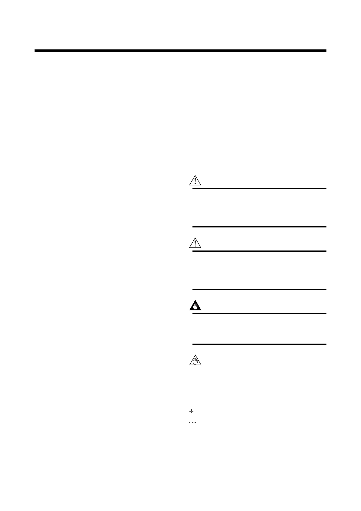
• The following safety symbol marks are used in this user's
manual and instrument.
WARNING
A WARNING sign denotes a hazard. It calls attention
to procedure, practice, condition or the like, which, if
not correctly performed or adhered to, could result in
injury or death of personnel.
CAUTION
A CAUTION sign denotes a hazard. It calls attention
to procedure, practice, condition or the like, which, if
not correctly performed or adhered to, could result in
damage to or destruction of part or all of the product.
IMPORTANT
An IMPORTANT sign denotes that attention is
required to avoid damage to the instrument or system
failure.
NOTE
A NOTE sign denotes information necessary for
essential understanding of operation and features.
Functional grounding terminal
Direct current
iv
IM 1F6A0-01E
Page 6

Warranty
•The warranty of this instrument shall cover the period
noted on the quotation presented to the Purchaser at the
time of purchase. The Seller shall repair the instrument
free of charge when the failure occurred during the
warranty period.
• All inquiries on instrument failure should be directed to
the Seller’s sales representative from whom you purchased
the instrument or your nearest sales office of the Seller.
• Should the instrument fail, contact the Seller specifying
the model and instrument number of the product in
question. Be specific in describing details on the failure
and the process in which the failure occurred. It will be
helpful if schematic diagrams and/or records of data are
attached to the failed instrument.
• Whether or not the failed instrument should be repaired
free of charge shall be left solely to the discretion of the
Seller as a result of an inspection by the Seller.
■ The Purchaser shall not be entitled to
receive repair services from the Seller free
of charge, even during the warranty period,
if the malfunction or damage is due to:
•improper and/or inadequate maintenance of the instrument
in question by the Purchaser.
• handling, use or storage of the instrument in question
beyond the design and/or specifications requirements.
•use of the instrument in question in a location not
conforming to the conditions specified in the Seller's
General Specification or Instruction Manual.
•retrofitting and/or repair by an other party than the Seller
or a party to whom the Seller has entrusted repair
services.
•improper relocation of the instrument in question after
delivery.
• reason of force measure such as fires, earthquakes, storms/
floods, thunder/lightning, or other reasons not attributable
to the instrument in question.
INTRODUCTION
v
IM 1F6A0-01E
Page 7

INTRODUCTION
■ Using the Vortex Flowmeter Safely
WARNING
(1) Installation
• Installation of the vortex flowmeter must be
performed by expert engineer or skilled personnel. No operator shall be permitted to perform
procedures relating to installation.
• The vortex flowmeter is a heavy instrument.
Be careful that no damage is caused to personnel through accidentally dropping it, or by
exerting excessive force on the vortex flowmeter. When moving the vortex flowmeter, always
use a trolley and have at least two people carry
it.
•When the vortex flowmeter is processing hot
fluids, the instrument itself may become
extremely hot. Take sufficient care not to get
burnt.
•Where the fluid being processed is a toxic
substance, avoid contact with the fluid and
avoid inhaling any residual gas, even after the
instrument has been taken off the line for
maintenance and so forth.
•All procedures relating to installation must
comply with the electrical code of the country
where it is used.
(2) Wiring
• The wiring of the vortex flowmeter must be
performed by expert engineer or skilled personnel. No operator shall be permitted to perform
procedures relating to wiring.
• When connecting the wiring, check that the
supply voltage is within the range of the
voltage specified for this instrument before
connecting the power cable. In addition, check
that no voltage is applied to the power cable
before connecting the wiring.
• The functional grounding must be connected
securely at the terminal with the
mark to
avoid danger to personnel.
(3) Operation
• Only expert engineer or skilled personnel are
permitted to open the cover.
(4) Maintenance
• Maintenance on the vortex flowmeter should be
performed by expert engineer or skilled personnel. No operator shall be permitted to perform
any operations relating to maintenance.
•Always conform to maintenance procedures
outlined in this manual. If necessary, contact
Yokogawa.
• Care should be taken to prevent the build up of
dirt, dust or other substances on the display
panel glass or data plate. If these surfaces do
get dirty, wipe them clean with a soft dry cloth.
(5) Explosion Protected Type Instrument
• For explosion proof type instrument, the description in Chapter 10 “EXPLOSION PROTECTED TYPE INSTRUMENT” is prior to the
other description in this user's manual.
• Only trained persons use this instrument in the
industrial location.
• The functional grounding must be connected
to a suitable IS grounding system.
• Take care not to generate mechanical spark
when access to the instrument and peripheral
devices in hazardous locations.
(6) European Pressure Equipment Directive
(PED)
•When using the instrument as a PED-compliant
product, be sure to read Chapter 11 before
use.
vi
IM 1F6A0-01E
Page 8
1. HANDLING PRECAUTIONS
1. HANDLING PRECAUTIONS
The Model DY Vortex Flowmeter and Model DYA Vortex
Flow Converter are thoroughly tested at the factory before
shipment. When these instruments are delivered, perform a
visual check to ascertain that no damage occurred during
shipment.
This section describes important cautions in handling these
instruments. Read carefully before using them.
If you have any problems or questions, contact your nearest
YOKOGAWA service center or sales representative.
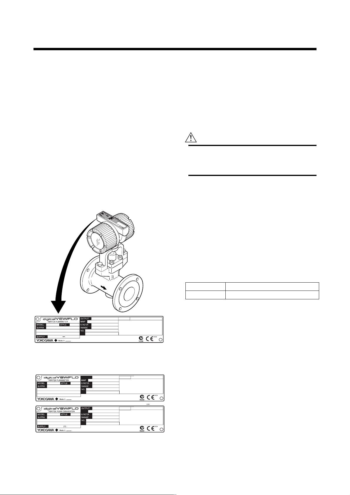
1.1 Model and Specifications
The model and important specifications are indicated on the
data plate attached to the case. Verify that they are the same
as those specified in the original order, referring to paragraph
9.2 to 9.5. In any correspondence, always give model
(MODEL), serial number (NO) and calibrated range
(RANGE) from the data plate.
3
U
A
1.2 Precautions Regarding Transportation and Storage Location
To protect against accidental damage to digitalYEWFLO
while transporting it to a new location, pack it in the original
packing as when shipped from the Yokogawa factory.
WARNING
The Vortex Flowmeter is a heavy instrument. Please
be careful to prevent persons from injuring when it is
handled.
Deterioration in insulation or corrosion can occur for
unexpected reasons if digitalYEWFLO is left uninstalled for
a prolonged period after delivery. If digitalYEWFLO is
likely to be stored over a prolonged period, observe the
following precautions.
■ Store the vortex flowmeter with forwarded statement.
■ Choose a storage location that satisfies the following
requirements:
• Not exposed to rain or splashwater.
• Less susceptible to mechanical vibration or shock.
•Kept within the temperature and humidity ranges shown
in the following table, preferably at normal temperature
and humidity (approximately 25°C, 65%)
Temperature
Humidity
–40°C to +80°C
5 to 100% (no condensation)
T010201.EPS
MPa at 38°C
MPa at 38°C
TAG NO.
F010101.EPS
TAG NO.
TAG NO.
F010102.EPS
4 ~ 20mA DC / PULSE
*1)
10.5 ~ 42V DC
*1): K factor at 15°C
*2): The product - producing country.
Figure 1.1(a) Example of Data Plate for Integral Type
10.5 ~ 42V DC
Figure 1.1(b) Example of Data Plate for Remote Type
*2)
4 ~ 20mA DC / PULSE
1.3 Precautions Regarding Installation Locations
3UA
3WA
3YA
(1) Ambient Temperature
Avoid an area which has wide temperature variations.
When the installation area is subjected to heat radiation
from process plant, ensure adequate heat prevention or
ventilation.
(2) Atmospheric Conditions
Avoid installing the vortex flowmeter in a corrosive
atmosphere. When the vortex flowmeter must be
installed in a corrosive atmosphere, adequate ventilation
must be provided.
1-1
IM 1F6A0-01E
Page 9

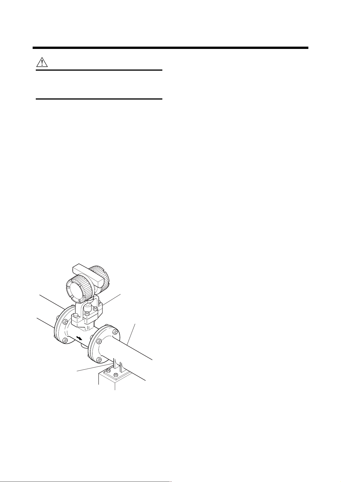
(3) Mechanical Shock or Vibration
The vortex flowmeter is of sturdy construction, but
select an area subject to minimize mechanical vibrations
or impact shock. If the flowmeter is subject to vibrations, it is recommended that pipeline supports to be
provided as shown in Figure 1.2.
(4) Other Considerations
• Choose a location where is sufficient clearance around
digitalYEWFLO exist to allow such work as routine
inspections.
• Choose a location that ensures easy wiring and piping.
digitalYEWFLO
Vortex Flowmeter
Pipeline
1. HANDLING PRECAUTIONS
Pipeline Support
Figure 1.2
F010301.EPS
1-2
IM 1F6A0-01E
Page 10
2. INSTALLATION
2. INSTALLATION
This instrument must be installed by expert engineer
or skilled personnel. The procedures described in this
chapter are not permitted for operators.
WARNING
2.1 Precautions Regarding Installation Locations
(1) Ambient Temperature
Avoid an area which has wide temperature variations.
When the installation area is subjected to heat radiation
from process plant, ensure adequate heat prevention or
ventilation.
(2) Atmospheric Conditions
Avoid installing the vortex flowmeter in a corrosive
atmosphere. When the vortex flowmeter must be
installed in a corrosive atmosphere, adequate ventilation
must be provided
(3) Mechanical Shock or Vibration
The vortex flowmeter is of sturdy construction, but
select an area subject to minimize mechanical vibration
or impact shock. If the flowmeter is subject to vibrations, it is recommended that pipeline supports to be
provided as shown in Figure 2.1.
(4) Precautions Regarding Piping
(a) Ensure that the process connector bolts are tightened
firmly.
(b) Ensure that no leak exists in the process connection
pipeline.
(c) Do not apply a pressure higher than the specified
maximum working pressure.
(d) Do not loosen or tighten the flange mounting bolts when
the assembly is pressurized.
(e) Handle the vortex flowmeter carefully when measuring
dangerous liquids, so that the liquids do not splash into
eyes or on face. When using dangerous gases, be careful
not to inhale them.
2.2 Piping
See Table 2.1 about Valve Position and Straight Pipe Length
and so on.
Pipeline Support
Figure 2.1
digitalYEWFLO
Vortex Flowmeter
Pipeline
F020101.EPS
2-1
IM 1F6A0-01E
Page 11
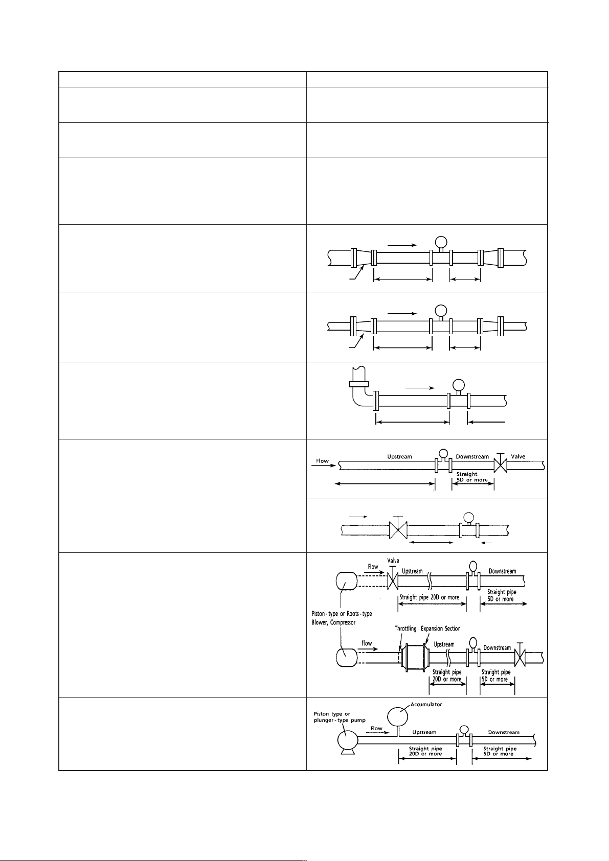
Table 2.1 Installation
2. INSTALLATION
Description
Piping support:
Typical vibration immunity level is 1G for normal piping condition.
Piping support shoud be fixed in case of over 1G vibration level.
Installation direction:
If a pipe is always filled with liquids, the pipe can be installed
vertically or at inclined angle.
Adjacent pipes:
The process pipline inner diameter should be larger than
the digitalYEWFLO inner diameter.
Use the following adjacent pipe.
Norminal size 15mm up to 50mm : Sch 40 or less.
Norminal size 80mm up to 300mm : Sch 80 or less.
Reducer pipe:
Ensure the upstream straight pipe length to be 5D or more, and the
downstream straight pipe length to be 5D or more for per reducer
pipe.
(D: digitalYEWFLO nominal diameter)
Expander pipe:
Ensure the upstream straight pipe length to be 10D or more, and
the downstream straight pipe length to be 5D or more for per
expander pipe.
Bent pipe and straight pipe length:
Ensure the upstream straight pipe length to be 10D or more, and
the downstream straight pipe length to be 5D or more for per bent
pipe.
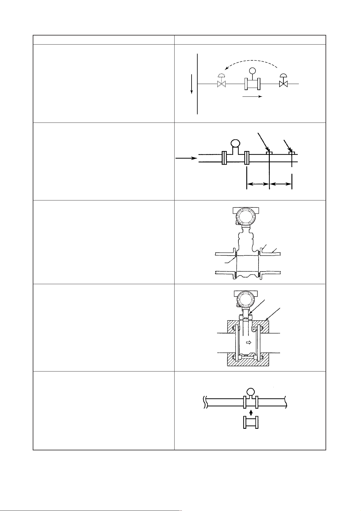
Valve position and straight pipe length:
■ Install the valve on the downstream side of the flowmeter.
The upstream straight pipe length dependent on the element
located on the upstream such as reducer/expander, bent and
etc., refer to description as above. Keep 5D or more for
downstream straight pipe length.
■ In case the valve has to be installed on the upstream of the
flowmeter, ensure the upstream straight pipe length to be 20D
or more, and the downstream straight pipe length be 5D or more.
Fluid vibration:
For a gas line which uses a position-type or roots-type blower
compressor or a high-pressure liquid line (about 1MPa or more)
which uses piston-type or plunger-type pump, fluid vibrations may
be produced.
In this case, install valve on the upstream side of digitalYEWFLO.
For inevitable fluid vibration, put a vibration damping device such as
throttling plate or expansion section in the upstream side of
digitalYEWFLO.
Reducer
Expander
Refer to each element above for
straight pipe run.
Flow
Figure
digitalYEWFLO
Flow
5D or more
digitalYEWFLO
Flow
10D or more
Flow
10DxN or more
N: Number of bent pipe
digitalYEWFLO
Valve
20D or more
5D or more
5D or more
digitalYEWFLO
5D or more
digitalYEWFLO
5D or more
digitalYEWFLO
digitalYEWFLO
Piston-type or plunger pump:
Install the accumulator on the upstream side of digitalYEWFLO to
reduce fluid vibrations.
2-2
digitalYEWFLO
F020102-1.EPS
IM 1F6A0-01E
Page 12
2. INSTALLATION
Description
Valve positon (T-type piping exist):
When pulsation causes by a T-type piping exist, install the valve
on the upstream of the flowmeter.
Example:As shown in the figure, when the valve V1 is turned
off, the fluid flow throught B as to meter A the flow is zero. But
due to the pulsating pressure is detected, the meter is zero
point become fluctuating. To avoid this, change the valve V1
location to V1'.
Pressure and Temperature T aps:
Pressure tap outlet: install this tap between 2D and 7D on the
downstream side of a flowmeter.
Temperature tap outlet: install this on the downstream side 1D
to 2D away from a pressure tap.
Mounting Gasket:
Avoid mounting gaskets which protrude into the pipe line. This
may cause inaccurate readings.
Use the gaskets with bolt holes, even if digitalYEWFLO is the
wafer type.
When using a spiral gasket(without bolt holes), confirm the size
with the gasket -manufacturer, as standard items may not be
used for certain flange ratings.
Flow
Flow
B
Relocating
Upstream
Figure
digitalYEWFLO
V1’ V1
A
Pressure tap
digitalYEWFLO
2 to 7D 1 to 2D
digitalYEWFLO
Valve (Off)
Temperature tap
Pipeline Flange
Pipeline
downstream
Heat-Insulation:
When an integral-type flowmeter or a remote type detector is
installed and the pipe carrying higt-temperature fluids is
heat-insulated, do not wrap adiabatic materials around the
installation bracket of the converter.
Flushing of the pipe line:
Flush and clean scale, incrustation and sludge on the inside of
pipe for newly installed pipe line and repaired pipe line before
the operation. For flushing, the flow should flow through
bypass-piping to avoid damaging the flowmeter. If there is no
bypass-piping, install short pipe instead of the flowmeter.
No good
digitalYEWFLO
Bracket
Heat-Insulator
digitalYEWFLO
Short pipe
2-3
F020102-2.EPS
IM 1F6A0-01E
Page 13
2. INSTALLATION
2.3 Precautions Regarding Installation
WARNING
In case of high process temperature, care should be
taken not to burn yourself because the surface of
body and case reach a high temperature.
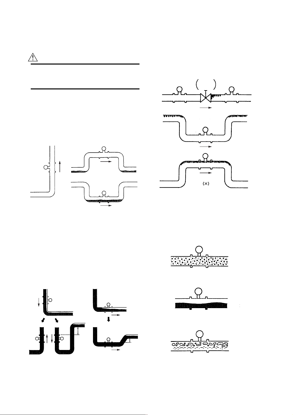
(1) Gas or Steam Measuring Precautions
•Piping to Prevent Standing Liquid
Mount digitalYEWFLO in a vertical pipeline to avoid
liquid traps. When digitalYEWFLO is installed horizontally, raise that part of the pipeline in which the
digitalYEWFLO is installed.
(Good)
(Good)
Flow
Flow
•Piping for Avoiding Bubbles
Flows containing both gas and liquid cause problems.
Avoid gas bubbles in a liquid flow. Piping should be
carried out to avoid bubble generation.
Install the valve on the downstream side of the flowmeter because pressure drop across the control valve may
cause gas to come out of the solution.
(Good)
Control
Value
Flow
(Good)
Flow
Flow
(No Good)
(No Good)
Flow
Figure 2.2
(2) Liquid Measurement Precautions
To insure accurate measurement, the digitalYEWFLO
must always have a full pipe.
• Piping Requirements for Proper Operation
Allow the flow to flow against gravity. When the flow is
moving with gravity, lift the down-stream pipe length
above the digitalYEWFLO installation level to maintain
full pipeline.
Flow
(No Good) (No Good)
Flow
(Good)
h h>0
Flow
(Good)
Flow
F020301.EPS
h
h>0
F020303.EPS
Figure 2.4
(3) Multi-Phase Flow
digitalYEWFLO can measure gas, liquid and steam
when there is no change in state. However, accurate
measurement of mixed flows (e.g. gas and liquid) is not
possible.
(No Good)
Mist flow
(No Good)
Liquid
Flow
Stratified flow
(No Good)
Gas Flow
Figure 2.3
F020302.EPS
2-4
Figure 2.5
Bubble flow
F020304.EPS
IM 1F6A0-01E
Page 14
2. INSTALLATION
(4) Pipeline Diameter and digitalYEWFLO
The process pipeline inner diameter should be slightly
larger than the vortex flowmeter inner diameter,
schedule 40 or lower pipe should be used for 1/2 to 2
inch flowmeters and schedule 80 or lower pipes for 3 to
8 inch flowmeters.
(No Good) (Good)
Figure 2.6
D
D
1
2
<
D
D
1
2
D1D
D
2
D
1
2
F020305.EPS
(5) Waterproof Construction
The vortex flowmeter is of IP67, NEMA4X
tightprotection. However, it cannot be used under water.
2.4 Piping to Improve Durability
(1) Pipe cleaning
• Flushing of pipe line (Cleaning)
Flush and clean scale, incrustation and sludge on the
inside of pipe wall for newly installed pipe line and
repaired pipe line before the operation.
• Fluid Carrying Solids
Do not measure fluids that carry solids (e.g. sand and
pebbles). Make sure users periodically remove solids
adhering to the vortex shedder.
• Obstruction of flow fluids may cause to make a chemical
reaction and the fluid will be crystallized and hardened,
and be deposited on the pipe wall and shedder bar.
In those cases, clean shedder bar.
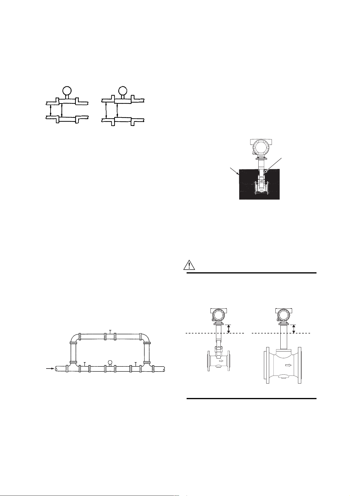
(2) Bypass piping
Installing a bypass, as illustrated in the figure below,
permits the digitalYEWFLO to be checked or cleaned
conveniently (vortex shedder, etc.).
Bypass shut-off valve
(1) Installing Cryogenic Vortex Flowmeter
For cryogenic applications, use stainless steel mounting
bolts and nuts to install the flowmeter. These can be
ordered separately from YOKOGAWA. Cover the
flowmeter body with heat insulating material so that the
flowmeter can be maintained at ultra-low temperatures
(refer to the Figure 2.8).
(2) Maintenance for Cryogenic Applications
DY/LT uses special materials that produce vortex
flowmeter for cryogenic applications. When you are
replacing a shedder bar, specify cryogenic type shedder
bar. To avoid condensing in the terminal box, ensure that
the wire connecting port is well sealed.
Bracket
Cold insulating material
Figure 2.8
F020501.EPS
(3) Installing High Process Temperature
Vortex Flowmeter
Installation of the flowmeter is the same as the standard
type. Cover the flowmeter body with heat insulating
material following instruction of “CAUTION”.
CAUTION
Keep the upper limit of heat insulating material to
prevent overheating of the terminal box.
Seal the heat insulating material to avoid hot-air
leakage.
50mm min. 50mm min.
UPPER LIMIT OF
HEAT INSULATING
MATERIAL
UPPER LIMIT OF
HEAT INSULATING
MATERIAL
digitalYEWFLO
Flow
Upstream shut-off valve Downstream shut-off valve
F020401.EPS
Figure 2.7
2.5 Cryogenic and High process
Temperature Version Insulation
When you are using cryogenic type and high process
temperature version of digitalYEWFLO Vortex Flowmeter
(Option code/HT /LT), refer to illustrated insulation method
as shown in Figure 2.8
Nominal Size: 100mm or under
Nominal Size: 150mm or over
(4) Maintenance for High Process Tempera-
ture Applications
DY/HT uses special materials that produce vortex
flowmeter for High Process Temperature applications
When you are replacing a shedder bar or a gasket,
specify High Process Temperature type.
2-5
F020501a.EPS
IM 1F6A0-01E
Page 15

2. INSTALLATION
2.6 Installing the Vortex Flowmeter
WARNING
The Vortex Flowmeter is a heavy instrument. Please
be careful to prevent persons from injuring whin it is
handled.
Before installing the instrument verify the following. The
direction of flow should match to the arrow mark on the
instrument body. When changing the orientation of the
terminal box, refer to "7.1."
Installation of Vortex flowmeter of the wafer and flange type
is shown in Table 2.3.
When installing the wafer type vortex flowmeter, it is
important to align the instrument bore with the inner diameter
of the adjacent piping.
To establish alignment, use the four collars supplied with the
instrument.
1. Four collars are supplied for 1/2 inch (15mm) to 1- 1/
2inch (40mm), 2 inch of JIS 10K or ANSI class 150 or
JPI class 150, and 3 inch of ANSI class 150 or JPI class
150. Install the instrument as illustrated in Table 2.2.
2. If the adjacent flanges have eight bolt holes, insert the
stud bolts in the holes on the instrument shoulder. Refer to
Figure 2.9.
Stainless steel stud bolts and nuts are available on order.
When they are to be supplied by the user, refer to Table
2.2 for stud bolt length. Gaskets must be supplied by the
user.
3. Gasket:
Avoid mounting gaskets which protrude into the pipeline.
This may cause inaccurate readings.
Use gaskets with bolt holes, even if digitalYEWFLO is of
the wafer type. Refer to Figure 2.10.
When using a spiral gasket (without bolt holes), confirm
the size with the gasket-manufacturer, as standard items
may not be used for certain flange ratings.
Table 2.2
Size
mm
(inch)
15mm
(1/2B)
25mm
(1B)
40mm
(1-1/2B)
50mm
(2B)
80mm
(3B)
100mm
(4B)
d
Figure 2.9
Flange Rating
JIS 10K, 20K/DIN 10,
16,25,40
JIS 40K
ANSI 150, 300, 600
JIS 10K, 20K, 40K
ANSI 150
ANSI 300, 600
DIN 10, 16, 25, 40
JIS 10K, 20K/DIN 10,
16, 25, 40
JIS 40K
ANSI 150
ANSI 300, 600
JIS 10K, 20K, 40K/
DIN 10, 16, 25, 40
ANSI 150, 300, 600
JIS 10K/DIN 10, 16,
25, 40
JIS 20K, 40K
ANSI 150
ANSI 300, 600
JIS 10K/DIN 10, 16
JIS 20K/DIN 25, 40
JIS 40K
ANSI 150
ANSI 300
ANSI 600
Length
Major Diameter of
External Threed of
Stud Bolt d (mm)
12
16
12.7
16
12.7
15.9
12
16
20
12.7
19.1
16
15.9
16
20
15.9
19.1
16
20
22
15.9
19.1
22.2
R
Collar
Pipeline Flange
Pipeline
Length
R(mm)
160
160
155
160
155
160
160
160
170
155
170
200
220
240
220
240
270
240
240
270
T020601.EPS
Stud Bolt
F020601.EPS
2-6
F020602.EPS
Figure 2.10
IM 1F6A0-01E
Page 16
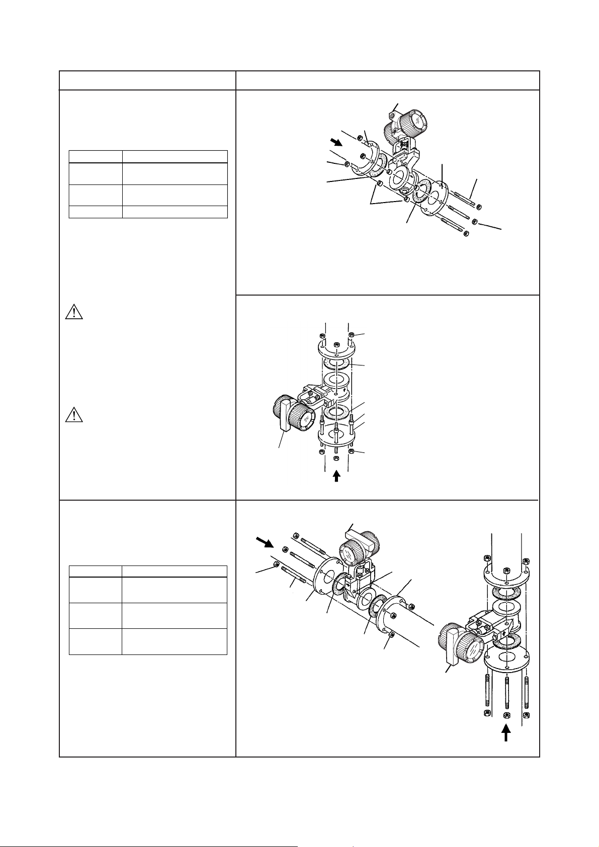
Table 2.3(a) Installation of Wafer Type Vortex Flowmeter
2. INSTALLATION
Wafer type
When Installation Collar are required, the
installation vortex flowmeters applied to the
following line sizes and flange ratings.
Size mm(inch)
15 to 40
(1/2 to 1-1/2)
50(2)
80(3)
Flange Rating
All ratings
JIS 10K, ANSI class 150,
DIN PN10 to PN40
ANSI class 150, JPI class 150
WARNING
The inside diameter of the gasket must
be larger than the pipe inner diameter
so that it will not disturb the flow in the
pipeline.
WARNING
When installing the Flowmeter vertically in the
open air, change the electrical connection port
direction to the ground. If the electrical
connection port is installed upwards, rain
water might leak in.
Description
Horizontal Installation
Flow
Direction
Nut
Gasket
(1) Insert four collar on each of the four bolts and check
that all four collars contact the outside diameter of
the flowmeter body.
(2) Tighten the four bolts uniformly. Check for leakage
from the flange connections.
Flange
Collar
Electrical Connection
Flange
Gasket
Vertical Installation
(1) Insert two each collars on
each of the lower two bolts.
(2) Place the flowmeter body
on the lower two bolts.
(3) Tighten the four bolts
(including upper two bolts)
and nuts uniformly.
(4) Check for leakage from
the flange connections.
Electrical
connection
Nut
Gasket
Gasket
Collar
Stud Bolt
(4 pcs.)
Nut
Stud Bolt (4 pcs.)
Nut
When Installation Collars are not required,the
installation vortex flowmeters applied to the
following line sizes and flanges.
Size mm(inch) Flange Rating
50(2)
80(3)
100(4)
JIS 20K, 40K
ANSI class 300,600
JPI class 300,600
JIS 10K, 20K, 40K
ANSI class 300, 600
JPI class 300,600
JIS 10K, 20, 40K
ANSI class 150, 300, 600
JPI class 150,300,600
Flow Direction
Flow
Direction
Nut
Stud Bolt (8 pcs.)
Flange
Gasket
Electrical Connection
Gasket
(1) Insert two stud bolts in the bolt holes
on the flowmeter shoulder to align
the instrument body with the inner
diameter of the adjacent piping.
(2) Tighten all bolts uniformly and check
that there is no leakage between the
instrument and the flanges.
Bolt Hole
Nut
Flange
Vertical InstallationHorizontal Installation
Electrical
Connection
Flow Direction
T020602.EPS
2-7
IM 1F6A0-01E
Page 17
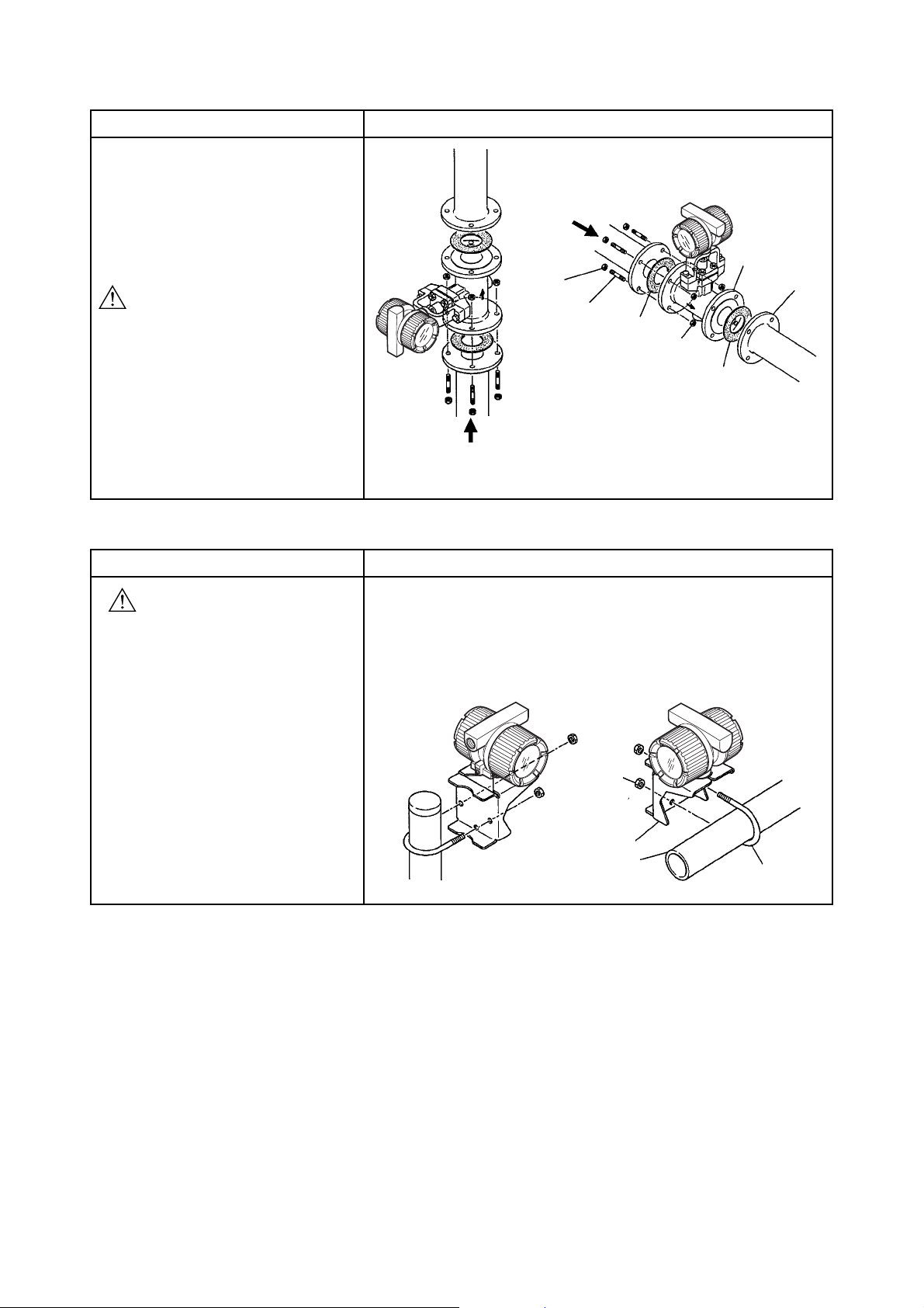
Table 2.3(b) Installation of Flange Type Vortex Flowmeter
Flange type Description
2. INSTALLATION
Use the stud bolts and nuts supplied with the
flowmeter of the user.
The gaskets should be supplied by the user.
CAUTION
The inside diameter of the gasket must be
larger than the pipe inner diameter so that it
will not disturb the flow in the pipeline.
Table 2.3(c) Installation of remote Type Converter
Remote type converter Description
CAUTION
A signal cable (DYC) is used between the
remote type flowmeter and the converter.
The maximum signal cable length is 97.5ft
(30m).
The converter is mounted on a 2-inch (60.5mm outer dia.) stanchion or horizontal
pipe.
Do not mount the converter on a vertical pipe. It makes wiring and maintenance
difficult.
The converter mounting orientation can be changed as illustrated below.
Flow Direction
Vertical Installation
Flow Direction
Nut
Stud Bolt
Horizontal Installation
Flange
Flange
Gasket
Nut
Gasket
T020603.EPS
Horizontal Pipe MountingStanchion Mounting
2-8
Nut
Bracket
2-inch Pipe
U-Bolt
T020604.EPS
IM 1F6A0-01E
Page 18
3. WIRING
3. WIRING
WARNING
The wiring of the vortex flowmeter must be performed
by expert engineer or skilled personnel. No operator
shall be permitted to perform procedures relating to
wiring.
CAUTION
Once all wiring is complete, check the connections
before applying power to the instrument. Improper
arrangements or wiring may cause a unit malfunction
or damage.
3.1 Wiring Precautions
Be sure to observe the following precautions when wiring:
CAUTION
• In cases where the ambient temperature
exceeds 50°C (122°F), use external heatresistant wiring with a maximum allowable
temperature of 70°C (158°F) or above.
• Do not connect cables outdoors in wet weather
in order to prevent damage from condensation
and to protect the insulation.
• Do not splice the cable between the flowtube
terminal and the converter if it is too short.
Replace the short cable with a cable that is the
appropriate length.
• All the cable ends must be provided with round
crimp-on terminals and be securely wired.
• Be sure to turn power off before opening the
cover.
• Before turning the power on, tighten the cover
securely.
• Explosion protected types must be wired in
accordance with specific requirement (and, in
certain countries, legal regulations) in order to
preserve the effectiveness of their explosion
protected features.
• The terminal box cover is locked by the clamp.
In case of opening the terminal box cover, use
the hexagonal wrench attached.
• Be sure to lock the cover by the clamp using
the hexagonal wrench attached after installing
the cover.
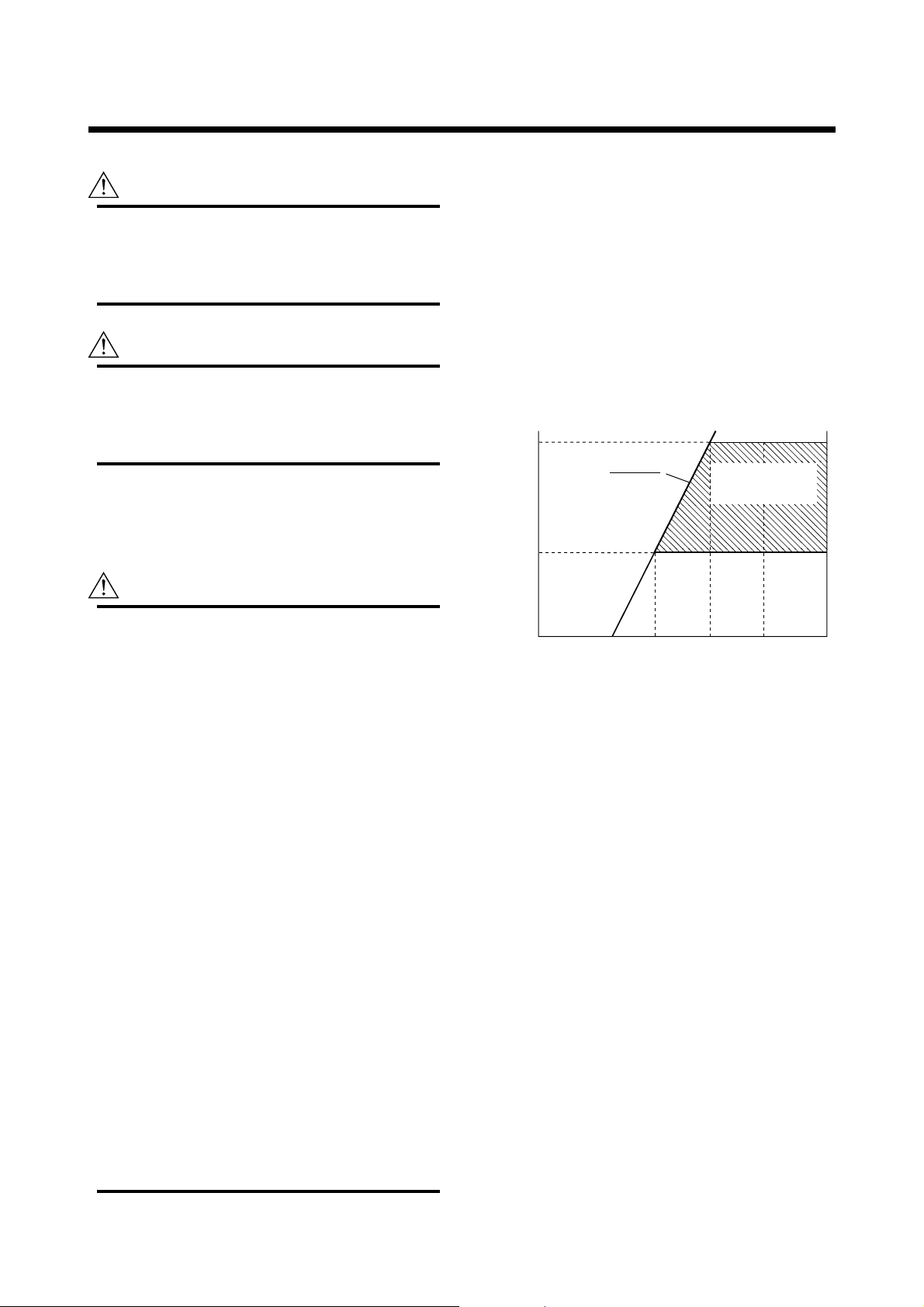
3.2 Wiring for Output Condition
Table 3.1 shows the connection method of several output
conditions.
(1) Analog Output (4 to 20 mA DC)
This converter uses the same two wires for both, the
signal and power supply. A DC power supply is required
in a transmission loop. The total leadwire resistance
including the instrument load and power distributor
(supplied by the user) must conform to a value in the
permissible load resistance range. Refer to Figure 3.1
shows.
600
E–10.5
R=
0.0236
250
Load resistance R (Ω)
10.5 16.4 24.7
Power Supply Voltage E (V)
Figure 3.1 Relationship between Power Supply Voltage
and Load Resistance (4 to 20 mA DC Output)
(2) Pulse output and Alarm, Status Output
This version uses three wires between the converter and
the power supply. A DC power and load resistance are
required, and pulse output is connected to a totalizer or
an electric counter. Low level of the pulse output is 0
to 2V. No communication is possible over a transmission line. Communication via the amplifier board is
always possible irrespective of the wiring condition.
(3) Simultaneous Analog-Pulse Output
When using digitalYEWFLO in the simultaneous analog
-pulse output mode, the communicable distance of the
transmission line is restricted on the wiring method.
Table 3.1 shows the examples of connection for this
output mode. Communication via the amplifier board is
always possible irrespective of the wiring condition.
Communication
Applicable range
BRAIN and HART
30 42
F030201.EPS
3-1
IM 1F6A0-01E
Page 19

IMPORTANT
For pulse output and the simultaneous analog-pulse
output ,use the load resistance. Refer to Table 3.1.
3.3 Connection
Table 3.1 shows the connection sample of connection for
power supply and load resistance. The terminal position of
each connection is shown in Figure 3.2.
3. WIRING
Integral type
Input Terminal from built-
T
in temperature sensor
Input Terminals from
A
vortex detector
B
Common Terminal
C
Figure 3.2
Remote type
Supply
4 to 20 mA DC Output Power Supply
and Output Signal Terminals
–
Pulse
Pulse Output Terminal
F030301.EPS
3-2
IM 1F6A0-01E
Page 20
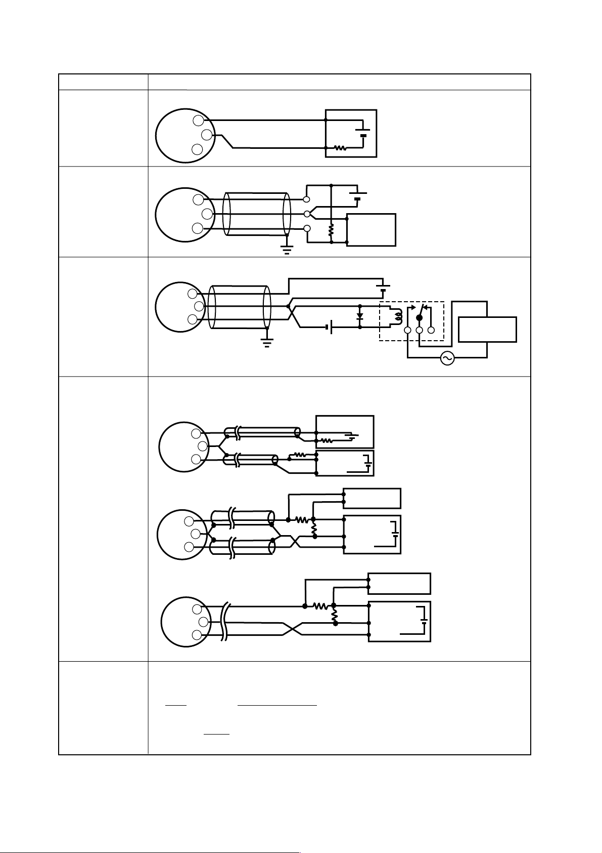
Table 3.1 The connection example for simultaneous analog and pulse and alarm, status output.
3. WIRING
Connection
Analog Output
In this case,
Communication is
possible (up to a distance
of 2km when a CEV cable
is used.)
Pulse Output
In this case,
No communication is
possible.
Status Output
Alarm Output
In this case,
No communication is
possible.
digitalYEWFLO Electrical Terminal
+
SUPPLY
–
+
PULSE
digitalYEWFLO Electrical Terminal
SUPPLY
+
Shielded Cable
–
+
PULSE
digitalYEWFLO Electrical Terminal
Shielded Cable
+
SUPPLY
–
PULSE
+
Description
Distributor
+
–
*2
External Power supply
30V DC, 120mA max
(Contact Rating)
R
24V DC
250Ω
Electric counter
Use the Three-wire shielded cable.
E
*1
Use the Three-wire shielded cable.
E
Relay
AC power supply
Mognetic
valve
Simultaneous
Analog
-Pulse Output
Example 1
In this case, Communica
-tion is possible(up to a
distance of 2km when a
CEV cable is used).
Example 2
In this case, Communica
-tion is possible (up to a
distance of 200m when a
CEV cable is used) and R
Ω
).
= 1k
Example 3
In this case, No communi
-cation is possible (when
shielded cable is not used).
The range of load
resistance R for
the pulse output.
*1 : To avoid the influence of external noise, use an electric counter which fits to the pulse frequency.
*2 : Resistor is not necessary in case of an electric counter which can receive contact pulse signal directly.
When analog and pulse output are used, the length of communication line is subjected to wiring conditions. Refer to
example 1 to 3. If the communication carries out from amplifier, no need to consider wiring conditions.
Distributor (or communication medium : ex. EP card)
Shielded Cable
+
SUPPLY
–
PULSE
+
digitalYEWFLO Electrical Terminal
Shielded Cable
+
SUPPLY
–
PULSE
+
digitalYEWFLO Electrical Terminal
+
SUPPLY
*2
R
250
250
E(10.5 to 30V DC)
Counting input
Common
Electric counter
Ω
*2
R
250
Ω
–
PULSE
+
digitalYEWFLO Electrical Terminal
The load resistance of pulse output should be used to 1k
24V DC
Ω
*2
R
For the shielded cables in this example of
flowmeter installation, use two-wire separately
shielded cables.
This supply voltage requires a power sourse
with a maximum output current of no less than
E/R.
(or communication medium : ex. EP card)
*1
Recorder or
other instrument
E(16.4 to 30V DC)
Counting input
Common
Electric counter
Recorder or
other instrument
E(16.4 to 30V DC)
Counting input
Common
Electric counter
Ω
, 2W.
If no translation of the pulse output possible by the cable length or the frequency of the pluse output,
the load resistance should be selected by calculation as shown below.
E (V)
120
P (mW) =
⬉ R (k
E
R (k
Ω
) ⬉
2
(V)
Ω
)
µ
F ) × f ( kHz )
C (
0.1
Where
E= Supply voltage (V)
f = Frequency of pulse output (kHz)
R = Value of load resistance (k
Example of CEV cable capacitance
ⱌ 0.1µF/km
Ω
3-3
For the shielded cables in this
example of flowmeter installation,
use two-wire separately shielded
cables.
This supply voltage requires a power
sourse with a maximum output current
of no less than E/R+25mA.
The supply voltage requires output
impedance no more than 1/1000 of R
*1
(load resistance).
This supply voltage requires
a power sourse with a
maximum output current of
no less than E/R+25mA.
*1
C= Cable capacitance (µF)
P= Power ratio of the load resistance
(mW)
)
T030301.EPS
IM 1F6A0-01E
Page 21
3. WIRING
3.4 Wiring Cables and Wires
The following should be taken into consideration when
selecting cables for use between the converter and distributor.
(1) Use 600V PVC insulated wire or equivalent standard
wire or cable.
(2) Use shielded wire in areas susceptible to electrical noise
(both analog and pulse output versions).
(3) In areas with high or low ambient temperatures, use
wires or cables suitable for such temperatures.
(4) In atmospheres where oils or solvents, corrosive gases or
liquids may be present, use suitable wires or cables.
(5) Use cable which withstand temperature up to 60°C and
more, when ambient temperature is more than 60°C.
IMPORTANT
For the remote type, use DYC signal cable to connect
the converter and remote type flowmeter(DY-N).
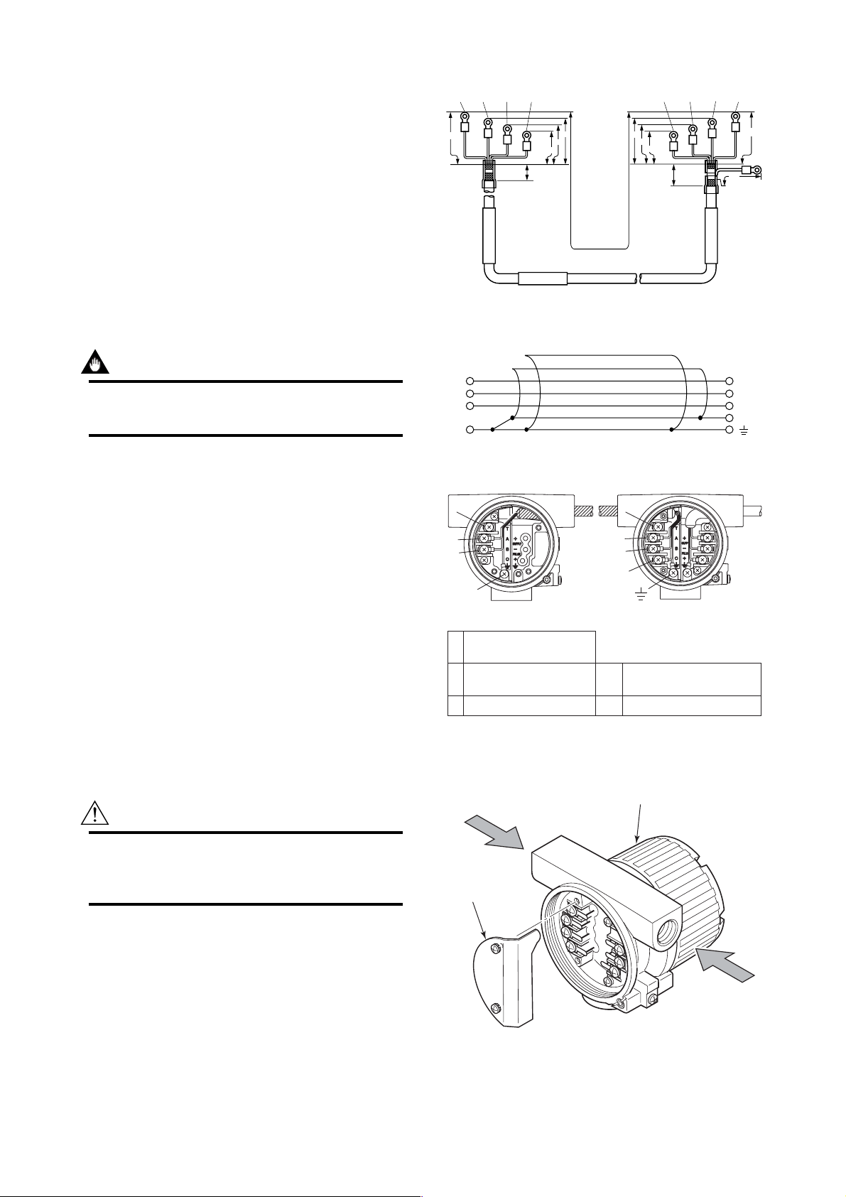
3.5 Connection of the Remote Type Signal Cable
The remote type signal cable is shown in Figure 3.3 and 3.4,
and the terminal is shown in Figure 3.5.
The maximum cable length is 30 m (97.5 feet).
Remove terminal box cover and wiring connection dust-cap
before wiring.
For remote type the converter has two electrical connections
(cable inlets). Use the left connection as viewed from the
terminal box for the DYC signal cable and the right connection for the transmission cable.
If a signal cable kit is supplied by YOKOGAWA, both ends
of the cable must be finished in accordance with the
following instructions as shown in 3.6.1 and 3.6.2.
(Black) (White) (Red) (Red) (White) (Black)
80
(Yellow) (Yellow)
70
60
50
20
Specified
Flowmeter
DYC
Length (L)
30m (max.)
70
60
50
Unit : mm
80
25
95
(Blue)
Converter
F030501.EPS
Figure 3.3 DYC Signal Cable
Outer shield
To Flowmeter
T
A
B
C
T: Only for / MV
Inner shield
To Converter
T
A
B
C
F030502.EPS
Figure 3.4 Construction of Remote Type Signal Cable
TT
A
B
C
Flowmeter(DY-N)
Input Terminal from built-
T
in temperature sensor
Input Terminals from
A
vortex detector
B
Common Terminal
C
T: Only for /MV
A
B
C
Converter(DYA)
Supply
4 to 20 mA DC Output Power Supply
and Output Signal Terminals
–
Pulse
Pulse Output Terminal
F030503.EPS
Figure 3.5 Terminal of Detector and Converter
CAUTION
After completing the signal cable connections, install
the shielded cover to signal cable terminal as shown
in Figure 3.6.
Signal Cable(DYC)
Shield Cover
Figure 3.6 Shielded Cover
3-4
Vortex Flow Converter
Power Vable
F030504.EPS
IM 1F6A0-01E
Page 22

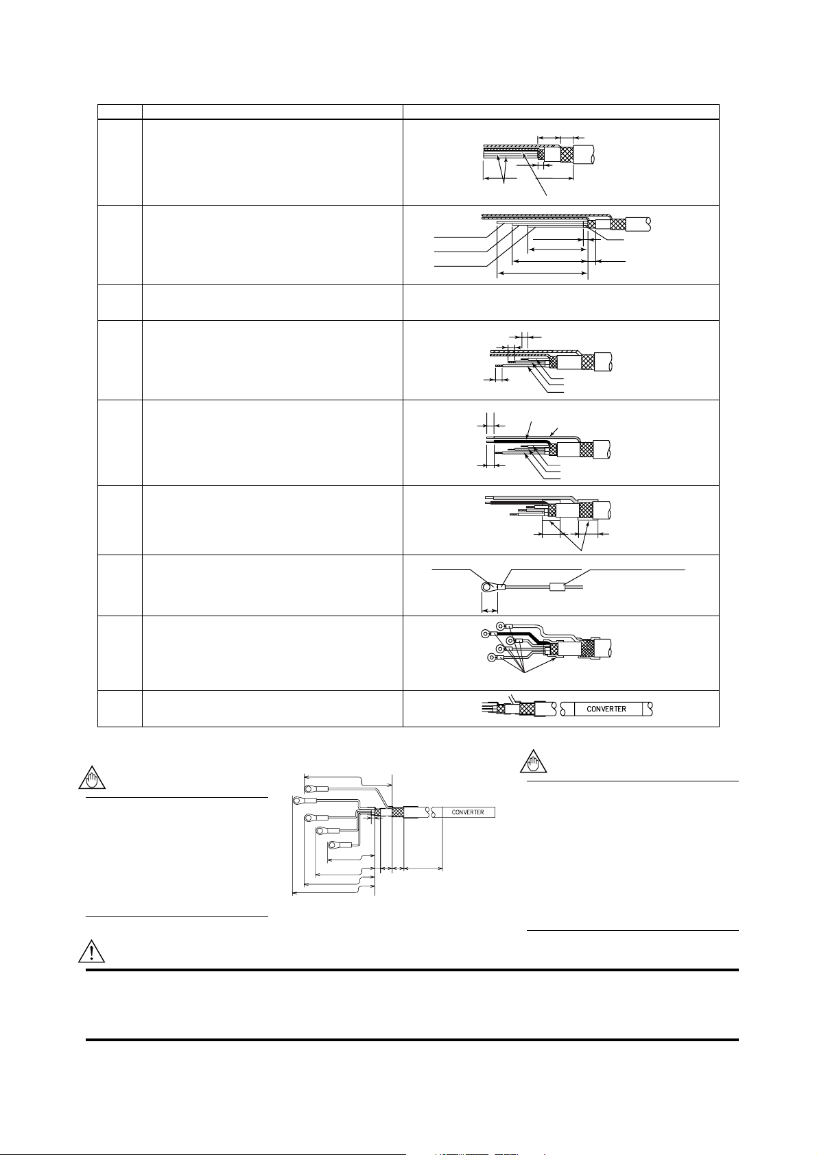
3.6 Method of Finishing the Signal Cable End(DYC)
3.6.1 For Vortex Flowmeter (DY-N)
Description Figure
1
Strip off the outer polyethylene jacket, outer braided
shield and inner jacket, and inner braided shield as
per the dimensions below.
2
Strip off the black conductive layer convering two
wires completely, as per the dimensions below.
Twist each of the conductor and drain wires so that
there are no free strands.
3
Do not short-circuit the conductive layer and the
terminals (A, B, C and T).
4
Strip off about 5 mm (0.2 in.) of insulation for each
of wires A, B, and T, and twist the strands of each
wire. Twist the inner and outer drain wires together.
5
Slide FEP (fluorinated ethylene propylene) tubing
over the twisted inner and outer drain wires C until
the tubing cannot be slid any further, and then cut
off the tubing leaving 5 mm (0.2 in.) of the stranded
drain wires exposed.
6
Slide heat shrinkable tubing over the cable end so
that the tubing covers the braided shield and
overlaps both the polyethylene jacket and loose
wires A, B, C, and T.
7
Slide a short piece of heat shrinkable tubing over
each of wires A, B, C, and T. Install a crimp-on
terminal lug at the tip of each wire. Crimp and
solder each lug.
8
Slide each short piece of heat shrinkable tubing
over the crimp sleeve. Heat all pieces of heat
shrinkable tubing with a heat blower or dryer.
9
Attach an identification label to the end of the cable.
T (Yellow)
B (White)
5 (0.2)
Lug tip
A (Red)
C
5 (0.2)
5 (0.2)
90 (3.5)
Black Conductive Layer
T (yellow)
40 (1.6)
3 (0.1)
or less
50 (2.0)
60 (2.4)
B (White)
Drain wires
C
A (Red)
5 (0.2)
C
10
T (Yellow)
5 (0.2)
5 (0.2)
Crimp and Solder Here
Heat Shrinkable Tubing
Heat Shrinkable Tubing
10 (0.4)
5 (0.2)
Black Conductive Layer
FEP Insulation Tubing
(Black)
T (Yellow)
A (Red)
B (White)
Heat Shrinkable Tubing
T (Yellow)
A (Red)
B (White)
3. WIRING
Unit : mm
(approx. inches)
(*1): Only for /MV
NOTE
Check that the insulation resistance between each wire including the inner shield is 10MΩ or
greater at 500V DC. Ensure that
both ends of the wires are
disconnected (open-circuited)
during the check.
80
BLACK
WHITE
(A)RED
Yellow(T) 50
Figure 3.7
(C)
(B)
3MAX
1055
120
Unit : mm
NOTE
In case that the cable end finish parts
assembly is necessary after delivery,
contact your nearest Yokogawa sales
60
70
F030601.EPS
office or the sales representative from
which you purchased the product. The
parts number of DYC cable end finish
parts assembly:
Standard type: F9399AB
T030601.EPS
Multivariable type (/MV): F9399AD
CAUTION
Do not touch the '' conductive layer" (black area covering the signal cables A and B) to the converter case, terminal,
and other leadwires. If it is touched, operation of the converter may be incorrect. When the cable is terminated,
remove the conductive layer properly.
3-5
IM 1F6A0-01E
Page 23
3.6.2 For Vortex Flow Converter (DYA)
Description Figure
1
Strip off the outer polyethylene jacket, outer braided
shield and inner jacket, and inner braided shield as
per the dimensions as shown.
2
Cut of the black conductive layers(convering the
two wires) completely, as per the dimensions below.
Twist each of the conductor and drain wires so that
there are no free strands.
3
Do not short-circuit the conductive layer and the
terminals (A, B, C, G and T).
4
Strip off about 5 mm (0.2 in.) of insulation for each
of wires A, B, and T, and twist the strands of each
wire.
Slide black FEP (fluorinated ethylene propylene)
5
tubing over the inner shield drain wire C and blue
FEP tubing over outer shield drain wire G until
the tubing cannot be slid any further, and then cut
off the tubing leaving 5 mm (0.2 in.) of the drain
wires exposed.
6
Slide heat shrinkable tubing over the cable end so
that the tubing covers the braided shield and
overlaps both the polyethylene jacket and loose
wires A, B, C, G, and T.
7
Slide a short piece of heat shrinkable tubing over
each of wires A, B, C, G, and T. Install a crimp-on
terminal lug at the tip of each wire. Crimp and
solder each lug.
8
Slide each short piece of heat
shrinkable tubing over the crimp sleeve. Heat all
pieces of heat shrinkable tubing with a heat blower
or dryer.
9
Attach an identification label to the end of the cable.
Black Conductive
Layer
B (White)
A (Red)
T (Yellow
Lug-Tips
95
(3.7)
(*1)
)
5 (0.2)
5 (0.2)
G
C
5 (0.2)
5 (0.2)
FEP Insulation Tubing (Black)
G
C
5 (0.2)
G
C
T
A
B
Crimp and Solder
10
(0.4)
Heat Shrinkable Tubing
15 (0.6) 10 (0.4)
5 (0.2)
T (yellow)
3 (0.1) or less
40 (1.6)
50 (2.0)
60 (2.4)
Drain wires
5 (0.2)
T (Yellow)
A (Red)
B (White)
FEP Insulation Tubing (Blue)
T (Yellow)
A (Red)
B (White)
25 (1.0)15 (0.6)
Heat Shrinkable Tubing
Heat-shrinkable tubing
3. WIRING
Unit : mm
(approx. inches)
Black
Conductive Layer
(*1): Only for /MV
NOTE
Check that the insulation
resistance between each wire
including the inner shield is
10MΩ or greater at 500V DC.
Ensure that both ends of the
wires are disconnected (opencircuited) during the check.
BLACK (C)
YELOW(T) 50
60
70
80
Figure 3.8
95
(G)BLUE
Unit : mm
NOTE
In case that the cable end finish parts
(B)WHITE
3
(A)RED
MAX
assembly is necessary after delivery,
contact your nearest Yokogawa sales
office or the sales representative from
which you purchased the product.
The parts number of DYC cable end
finish parts assembly:
Standard type: F9399AA
5
10 10
120
F030602.EPS
Multivariable type (/MV): F9399AC
T030602.EPS
CAUTION
Do not touch the '' conductive layer" (black area covering the signal cables A and B) to the converter case, terminal,
and other leadwires. If it is touched, operation of the converter may be incorrect. When the cable is terminated,
remove the conductive layer properly.
3-6
IM 1F6A0-01E
Page 24

3. WIRING
3.7 Wiring Cautions
(1) Lay wiring as far as possible from electrical noise
sources such as large transformers, motors and power
supplies.
(2) It is recommended that crimp-on type solderless lugs be
used for large wire ends.
(3) For general use, it is recommended that conduits and
ducts or racks be used to protect wiring from water or
mechanical damage. A rigid steel conduit or flexible
metal conduit is recommended. See Figure 3.9.
3.8 Grounding
IMPORTANT
When a lightning protector (option code: /A) is
selected, use a grounding resistance of 10Ω or less.
(1) The grounding terminals
outside of the terminal area. Either terminal may be
used.
(2) For pulse output version, ground the flowmeter. Also
ground the shielded cable between the converter and the
pulse receiver.
(3) Grounding should satisfy Class D requirements (ground
resistance 100Ω or less).
(4) Use 600V PVC insulated wire for grounding.
are located on the inside and
Figure 3.9
F030701.EPS
Figure 3.10
Integral Type
Grounding
terminals
F030801.EPS
3-7
IM 1F6A0-01E
Page 25
4. BASIC OPERATING PROCEDURES
4. BASIC OPERATING PROCEDURES
Data setting can be performed with the three keys on the front
panel (SET,SHIFT and INC) or using a handheld
BRAIN(BT) terminal and HART communicator.
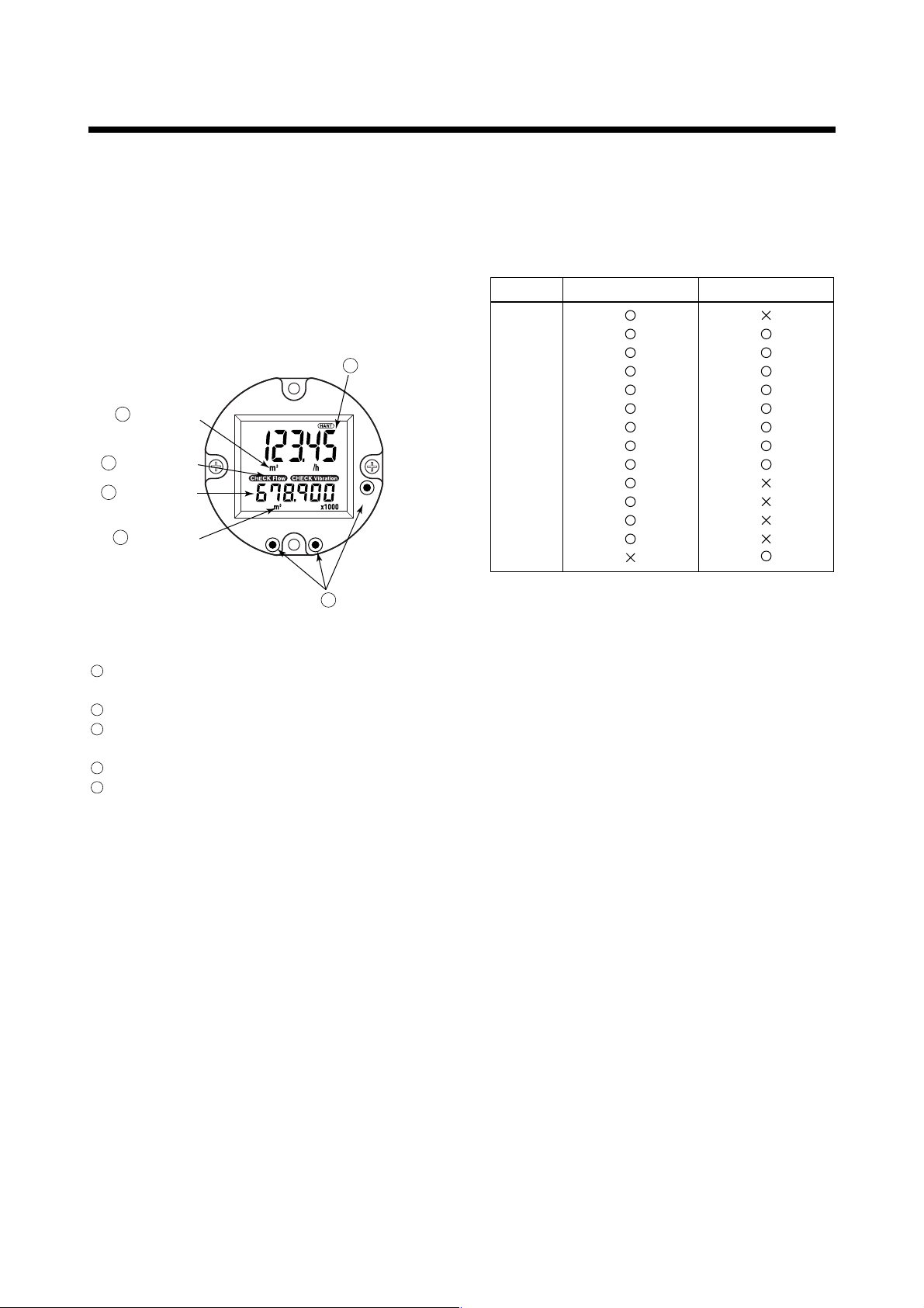
4.1 Construction of the Display
Figure 4.1 shows the configuration of the digitalYEWFLO
display panel (if equipped).
Data Display
1
(Upper)
Unit Display
4
Alarm Display
3
Data Display
2
(Lower)
Unit Display
4
INCSHIFT
SET
Setting Keys
5
F040101.EPS
■ Description of unit indications and its votes.
Table 4.1 shows the description of unit indications and
it's votes.
Table 4.1 Unit Indicator
Unit Upper Indication Lower Indication
%
3
m
艎
3
Nm
N艎
3
Sm
S艎
kg
t
/h
/m
/s
/d
°C
(*1) Only for /MV
(*1)
T040101.EPS
Figure 4.1 Construction of the Display
1
Data Display(Upper) :Displays flowrate data, setting
data, total data.
2
Data Display(Lower) :Displays total data, alarm data.
3
Alarm Display :Displays alarm of a flow error
and a vibration error.
4
Unit Display :Displays Flowrate unit.
5
Setting Keys : These keys are used to change
flow rate data displays and type
of setting data.
4-1
IM 1F6A0-01E
Page 26
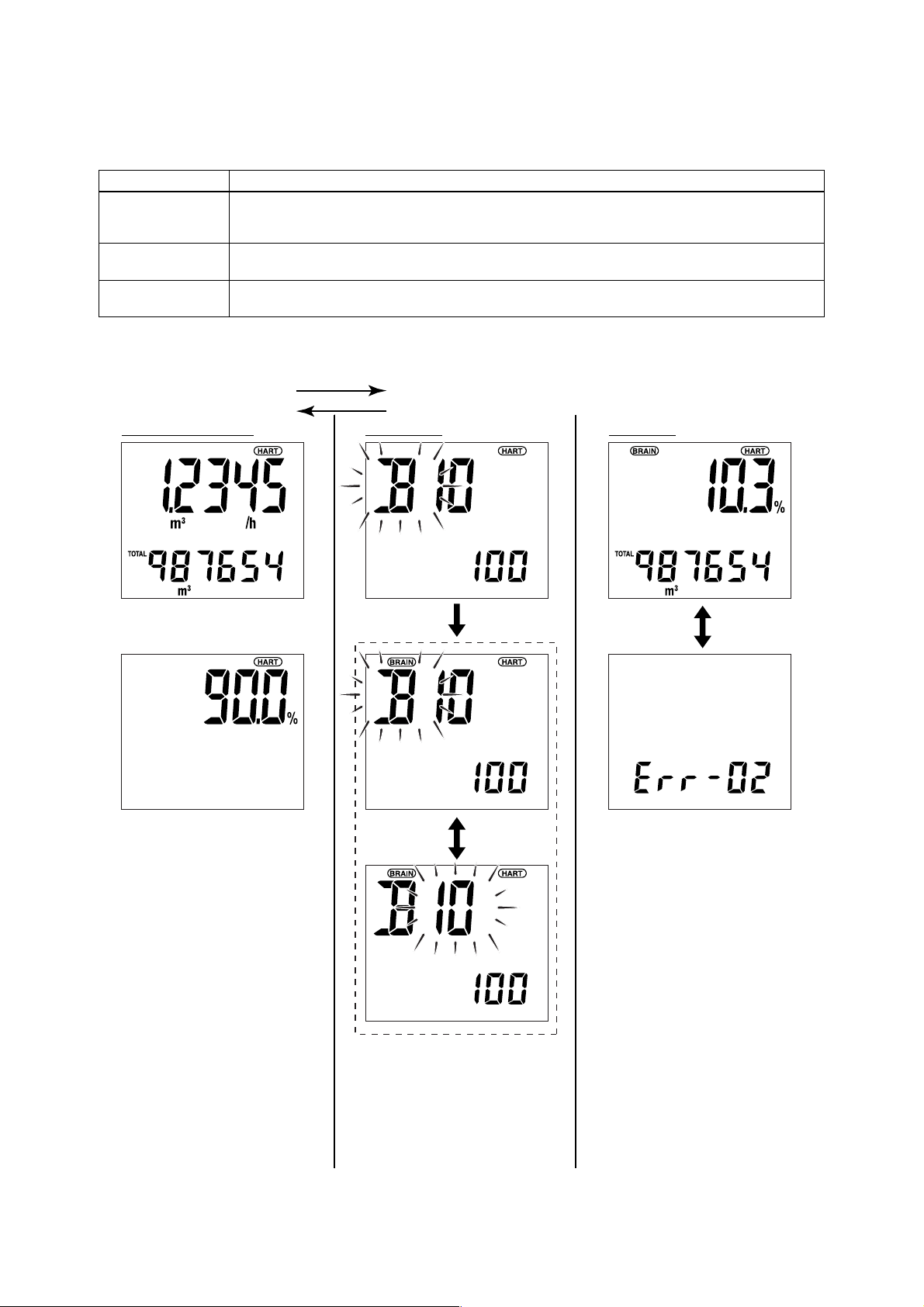
4.2 Display Contents in Display Section
The display content items are classified in the following three items.
Table 4.2 Mode Name List
Mode (status) Name Display Contents
Flowrate display
mode
Setting mode
Alarm number display
mode
Mode represents that the system is in a state where the relevant setting or display is possible.
● Display Example
Flowrate Display Mode Setting Mode Error Mode
A mode in which instantaneous flow rates or totalized values are displayed.
Display content is usually selected either in display content selection mode or by setting parameters
via BRAIN communication.
In this mode, parameter contents are confirmed or data is updated using the setting section. The mode is
changed to this mode when [SET] key is pressed in normal mode.
This mode is overlapped when an alarm is occurring in display mode. The alarm number presentation to
indicate alarm contents (about 2 sec) and the normal data display (about 4 sec ) are repeated alternatively.
SET
SHIFT + SET
4. BASIC OPERATING PROCEDURES
T040201.EPS
UPPER
Flow rate
UPPER
Flow rate (%)
This mode display can be selected
below.
• Upper display : Flow rate
• Lower display : Total rate or Blank
LOWER
Total rate
LOWER
Blank
Switching
of setting
number
SHIFT
• This mode is used to check parameter
content and rewrite data. This mode can
be called up from the flowrate display
mode by pressing the “SET” key.
• Setting item and setting number can be
changed when pressing “SHFT” key.
• This mode can be called up by pressing
“SET” key while pressing “SHIFT” key
when setting mode is displayed.
NORMAL
INDICATION
(4sec)
ERROR INDICATION
(2sec)
• When an alarm situation occurs,
this mode will replace the current
mode (flow rate or setting mode)
to show what type of alarm has
occurred.
• Refer to “5.5 Error Code Lists”
about the error descriptions and
error No.
Alternately
F040201.EPS
4-2
IM 1F6A0-01E
Page 27
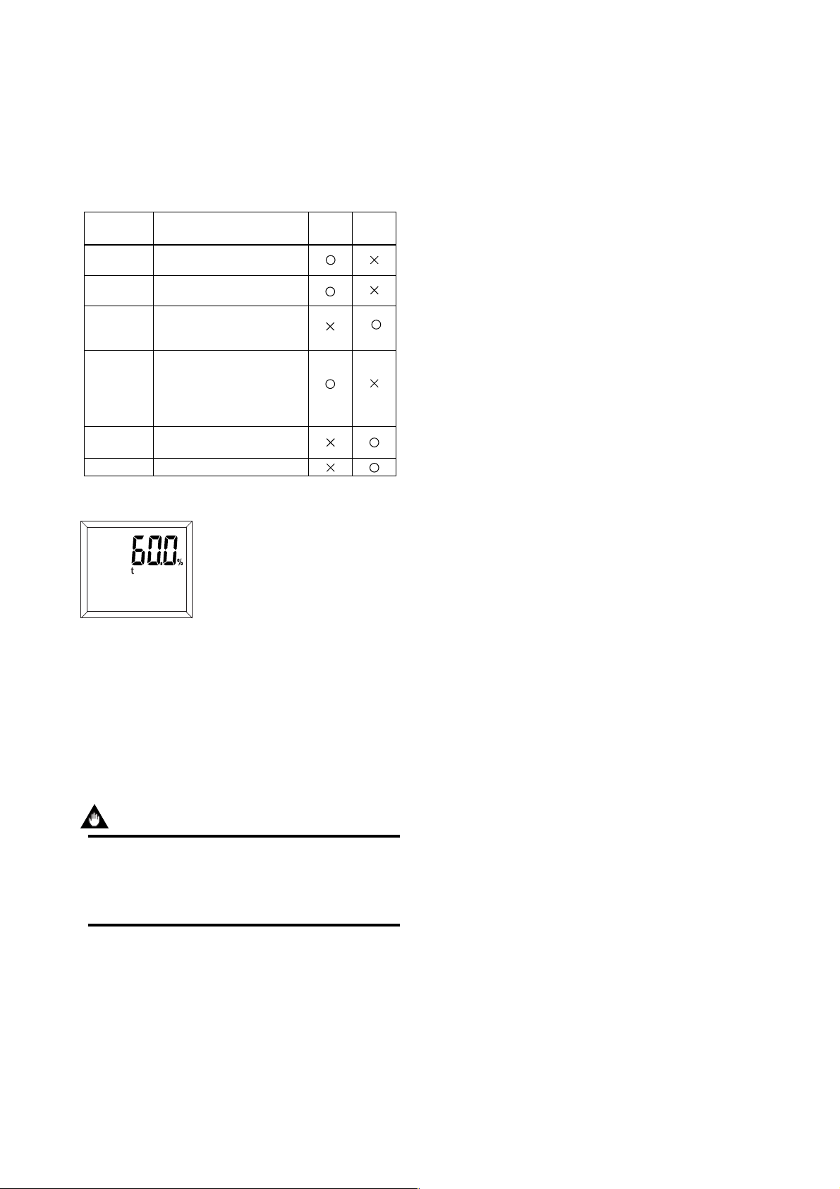
4.3 Display Contents in Display Section
The display mode is a mode in which instantaneous flow
rates or totalized flow are displayed. In display mode, there
are three display modes as shown in Table 4.3.
Table 4.3 Display Mode
Name Contents
% Display
(Flow rate)
Engineering
Display Unit
Totalized
Display
% Display
(Temperature)
(*1)
Temperature
display(*1)
(*1) When option code /MV is selected,
this function is available.
Instantaneous % flow rate is
displayed.
Instantaneous flow rate in an
engineering unit is displayed.
Totalized flow displayed
without indicating the decimal
point.
Instantaneous temperature is
displayed.
In this case, “t” is displayed
simultaneously (Refer to
Figure 4.2).
Temperature value is
displayed.
------Blank
Upper
Display
Lower
Display
T040301.EPS
4. BASIC OPERATING PROCEDURES
F040301.EPS
Figure 4.2 Example
Display mode can be changed using the BT200 terminal or
the indicator setting section.
• For operation using BT200, perform changes using the
parameter item “ B30:UPPER DISP” and “B31:LOWER
DISP” referring to section 5. Parameters.
• For operation using indicator, change B30 and B31
parameter item number to display an appropriate display.
IMPORTANT
After setting a parameter, keep the power on for at
least 30 seconds.
If the power of flowmeter is turned off, a parameter
setting is released.
4-3
IM 1F6A0-01E
Page 28
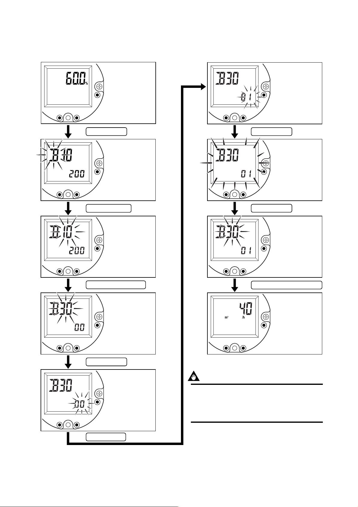
4. BASIC OPERATING PROCEDURES
4.3.1 Change the Display Mode from % Display to Engineering Unit
The display mode can be changed referring 5.3 parameter list.
SET
INCSHIFT
Press “ SET ” key.
SET
INCSHIFT
Press “ SHIFT ” key.
Indication of %
display.
Enter the setting
mode.
Enter the parameter
item.
Indicate “ 01 ” of
engineering unit
referring 5.3
parameter list.
SET
INCSHIFT
Press “ SET ” key.
Ensure the setting
data.
SET
INCSHIFT
Press “ SET ” key.
Finish the setting.
SET
INCSHIFT
Press “ INC ” key any time.
Indicate “ 30 ”
referring 5.3
parameter list.
SET
INCSHIFT
Press “ SET ” key.
Enter the data
input item.
SET
INCSHIFT
SET
INCSHIFT
Press “ SET ” and “ SHIFT ” key.
Return to display
mode.
SET
INCSHIFT
IMPORTANT
After setting a parameter, keep the power on for at
least 30 seconds.
If the power of flowmeter is turned off, a parameter
setting is released.
Press “ INC ” key.
4-4
F040302.EPS
IM 1F6A0-01E
Page 29

4.3.2 Indicate the Total Rate in the Lower Display
The display mode can be changed referring 5.3 parameter list.
4. BASIC OPERATING PROCEDURES
SET
INCSHIFT
Press “ SET ” key.
SET
INCSHIFT
Press “ SHIFT ” key.
Indication of
engineering unit
display.
Lower display is
“ Blank ”.
Enter to the setting
mode.
Enter to the
parameter item.
Indicate “ 01 ” of
lower the display
item referring 5.3
parameter list.
SET
INCSHIFT
Press “ SET ” key.
Ensure the setting
data.
SET
INCSHIFT
Press “ SET ” key.
Finish the setting.
SET
INCSHIFT
Press “ INC ” key any time.
Indicate “ 31 ”
referring 5.3
parameter list.
SET
INCSHIFT
Press “ SET ” key.
Enter the data input
item.
SET
INCSHIFT
SET
INCSHIFT
Press “ SET ” and “ SHIFT ” key.
Return to display
mode.
SET
INCSHIFT
IMPORTANT
After setting a parameter, keep the power on for at
least 30 seconds.
If the power of flowmeter is turned off, a parameter
setting is released.
Press “ INC ” key.
4-5
F040303.EPS
IM 1F6A0-01E
Page 30
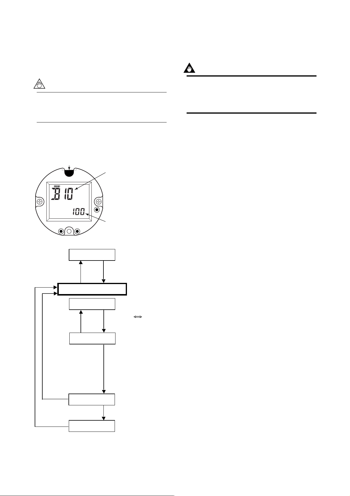
4. BASIC OPERATING PROCEDURES
4.4 Setting Mode
The setting mode is used for checking parameters and
rewriting data. The following is an overview of the setting
mode.
NOTE
•Refer to 5.3 Parameter List and 5.4 Parameter
description for information on how to change
setting.
4.4.1 Structure of Setting Mode Display
Simple parameter sheet
IN this sheet, a setting flow chart and the parameter list
required to operate digitalYEWFLO is indicated.
Item number
Change item number using
“SHIFT” key and “INC”key.
•When completing setting, press “SHIFT” key and “SET”
key simultaneously. The mode move to the “display
mode”.
IMPORTANT
After setting a parameter, keep the power on for at
least 30 seconds.
If the power of flowmeter is turned off, a parameter
setting is released.
INCSHIFT
Flowrate Display Mode
SHIFT+SET
Parameter Setting Mode
SHIFT+SET
SET
SET
Select Item
SET
Set Data
SET
Data number
Change the data number
using “SHIFT” key and
“INC” key.
F040401.EPS
SHIFT : Menu
INC : Inc. Menu / Item Number
Select T ype
INC : Inc. Data Number
Numeric Value Setting T ype
SHIFT : Move Cursor
INC : Inc. Numeric Value
Item Number
SHIFT or INC
Check Setting Data
SET
Fix Setting Data
F040401_1.EPS
Figure 4.3 Indicator Construction and Parameter Setting
Procedure
4-6
IM 1F6A0-01E
Page 31

4.4.2 Method of Parameter Setting
䊏 Input method of numeric data
Example 1: Change the span from 100m3/h to 150m3/h
The setting mode can be changed referring 5.3 parameter list
4. BASIC OPERATING PROCEDURES
INCSHIFT
Press “ SET ” key.
INCSHIFT
Press “ SET ” key.
Indication of % flow
rate.
SET
Enter to the setting
mode.
(Span number is
“ B10 ”)
SET
Enter to data number
item.
Ensure the setting
data.
SET
INCSHIFT
Press “ SET ” key.
Complete the Setting.
SET
INCSHIFT
Press “ SET ” and “ SHIFT ” key.
Return to display
mode.
SET
INCSHIFT
Press “ SHIFT ” key any time.
Move the position to
input the data.
SET
INCSHIFT
Press “ INC ” key any time.
Set “ 5 ” and indicate
“ 150m
SET
INCSHIFT
3
SET
INCSHIFT
IMPORTANT
After setting a parameter, keep the power on for at
least 30 seconds.
If the power of flowmeter is turned off, a parameter
setting is released.
/h ”.
Press “ SET ” key.
4-7
F040402.EPS
IM 1F6A0-01E
Page 32

䊏 Input method of selection items
Example 2: Change the pulse output to alarm output.
The setting mode can be changed referring 5.3 parameter list
4. BASIC OPERATING PROCEDURES
SET
INCSHIFT
Press “ SET ” key.
SET
INCSHIFT
Press “ SHIFT ” key.
Indication of % unit.
Enter to the setting
mode.
Enter to the
parameter item.
Indicate “ 03 ” of
alarm output item
referring 5.3
parameter list.
SET
INCSHIFT
Press “ SET ” key.
Ensure the setting.
SET
INCSHIFT
Press “ SET ” key.
Finish the parameter
setting.
SET
INCSHIFT
Press “ INC ” key any time.
Indicate “ 20 ”
referring 5.3
parameter list.
SET
INCSHIFT
Press “ SET ” key.
Enter to the data
input item.
SET
INCSHIFT
SET
INCSHIFT
Press “ SET ” and “ SHIFT ” key.
Return to display
mode.
SET
INCSHIFT
IMPORTANT
After setting a parameter, keep the power on for at
least 30 seconds.
If the power of flowmeter is turned off, a parameter
setting is released.
Press “ INC ” key any time.
4-8
F040403.EPS
IM 1F6A0-01E
Page 33

4. BASIC OPERATING PROCEDURES
4.5 Operation for the BT200
This section describes the operation procedures using a
BRAIN Terminal (BT200). For details on the functions of the
digitalYEWFLO, refer to 5.3 Parameter List. And also, see
the “BT200 Instruction Manual” (IM 1C0A11-01E) for more
detailed Information.
4.5.1 Connection Method for the BT200
(1) Connecting the BT200 to a 4 to 20mA DC
Transfer Line
The communication signal of the digitalYEWFLO is
superimposed onto the 4 to 20mA DC analog signal to
be transferred.
digitalYEWFLO
SUPPLY
SUPPLY
Inter mediate
terminals
4 to 20mA DC
Signal
transmission
line
Control room
Receiving
Terminal
instrument
Board
Receiver
Resistance
250 to 600Ω
(2) Connecting BT200 to Flow Converter
Removing a cover and indicator, the terminals for brain
communication are provided on the circuit board.
Connect BT200 to the terminal of HHT-COM on the
circuit board.
Display
Indicator Mounting
Screw (2 PCS)
P
Circuit board
BT200 BT200 BT200 BT200
Figure 4.4 Communicating for a 4 to 20mA DC Signal
Line
F040501.EPS
IMPORTANT
The communicable distance of the transmission line is
restricted depending on the wiring method. Refer to 3.
WIRING.
IMPORTANT
After setting a parameter, keep the power on for at
least 30 seconds.
If the power of flowmeter is turned off, a parameter
setting is released.
COM
HHT
BT200
Figure 4.5 Connection of BT200 to Flow Converter
TP2
F040502.EPS
4-9
IM 1F6A0-01E
Page 34

4. BASIC OPERATING PROCEDURES
4.5.2 Displaying Flow Rate Data
Flowrate data can be displayed on the BT200 screen
according to the following procedure.
Turn the power on and the
———WELCOME———
BRAIN TERMINAL
ID:BT200
Check connection
Push ENTER key
UTIL FEED
PARAM
01:MODEL
digitalYEWFLO
02:TAG NO.
03:SELF CHECK
GOOD
OK
MENU
A:DISPLAY
B:EASY SETUP
C:BASIC SETUP
D:AUX. SETUP
E:METER SETUP
H:ADJUST
HOME SET ADJ ESC
screen on the left
“Please wait....” is
displayed for a few
minutes.
Pressing the “ENTER” key
causes the initial data
screen on the left to be
displayed.
The tag number
specified upon
ordering is entered.
or
Inverse Video Bar
Pressing the “F4” or
“ENTER” causes the menu
screen on the left to be
displayed.
● Function key
The functions of the function keys vary with the commands
being displayed on the display panel.
Table 4.4
Command Description
ADJ
CAPS/caps
CLR
COPY*
DATA
DEL
DIAG
ESC
FEED*
HOME
LIST*
NO
OK
PARM
PON/POFF*
PRNT*
SET
SLOT
GO*
STOP*
UTIL
*The command is available only for BT-200-P00
Calls up the adjustment menu.
Changes the uppercase / lowercase mode.
Clears entered data / deletes all data.
Prints parameters on the screen.
Updates parameter data.
Deletes one character.
Calls up the self-check screen.
Returns to the preceding screen.
Paper feed.
Calls up the home menu (A : DISPLAY).
Prints all parameters of the menus.
Setting stop / re-setting. Returns to the
previous screen.
Goes to the next screen.
Parameter number setting mode.
Printer output of data whose setting was
changed Mode on / off.
Changes to the prints mode.
Calls up the setting menu (B : SETTING).
Returns to the slot selection screen.
Starts print out.
Stops printing.
Transfers to the utility screen.
T040501.EPS
PARAM
A10:FLOW RATE(
80.0
A20:FLOW RATE
100m3/h
A30:TOTAL
1417
DATA DIAG PRNT ESC
PARAM
A10:FLOW RATE(
80.0
A20:FLOW RATE
100m3/h
A30:TOTAL
1417
DATA DIAG PRNT ESC
%
)
%
%
)
%
Function Key
With “A : DISPLAY”
displayed on the menu
panel in the inverse video
bar, press “ENTER” key
and the flow data screen
appears.
Maximum three data items
can be displayed on one
screen.
Executing Function Key
F1 :
Updates the current data.
F2 : Displays the self-check
screen.
F3 : Displays the parameter
print sreen.
F4 : Returns to the previous
panel. (menu panel)
F040503.EPS
4-10
IM 1F6A0-01E
Page 35

4.5.3 Setting Parameters
This section describes the setting method using a BRAIN
Terminal (BT200). For details on the method, refer to 5.3
Parameter List.
(1) Setting Flow Span
Example : Change flow span 100m3/h to 150m3/h
4. BASIC OPERATING PROCEDURES
MENU
A:DISPLAY
B:EASY SETUP
C:BASIC SETUP
D:AUX. SETUP
E:METER SETUP
H:ADJUST
HOME SET ADJ ESC
PARAM
B10:FLOW SPAN
100 m3/h
B15:DAMPING
4 sec
B20:CONTACT OUT
SCALED PULSE
DATA DIAG PRNT ESC
SET
B10:FLOW SPAN
100 m3/h
0
DEL CLR ESC
Enter menu item, and press
“ ” key.
Move the inverse video bar
to “B : EASY SETUP”.
or
Move the inverse video bar
to “B10 : FLOW SPAN”.
The data setup screen is
displayed.
If the security screen is
displayed, enter the security
code.
SET
B10:FLOW SPAN
150.00 m3/h
FEED NO OK
PARAM
B10:FLOW SPAN
100 m3/h
B15:DAMPING
4 sec
B20:CONTACT OUT
SCALED PULSE
DATA DIAG PRNT ESC
The data setting can be
completed.
If data setting is missing,
press “F3” key and reset the
data.
Setting is completed.
The screen returns to the
preceding screen when the
“F4” (ESC) key is pressed.
F040504.EPS
IMPORTANT
After setting a parameter, keep the power on for at
least 30 seconds.
If the power of flowmeter is turned off, a parameter
setting is released.
SET
B10:FLOW SPAN
100.00 m3/h
150
DEL CLR ESC
SET
B10:FLOW SPAN
100.00 m3/h
150
print off
F2:printer on
FEED POFF NO
Enter “150” using the
alphanumeric keys.
Pressing the enter key,
inverse video bar is flashed.
4-11
IM 1F6A0-01E
Page 36

(2) Change the Pulse Output to Alarm Output.
4. BASIC OPERATING PROCEDURES
MENU
A:DISPLAY
B:EASY SETUP
C:BASIC SETUP
D:AUX. SETUP
E:METER SETUP
H:ADJUST
HOME SET ADJ ESC
PARAM
B10:FLOW SPAN
100 m3/h
B15:DAMPING
4 sec
B20:CONTACT OUT
SCALED PULSE
DATA DIAG PRNT ESC
PARAM
B10:FLOW SPAN
100 m3/h
B15:DAMPING
4 sec
B20:CONTACT OUT
SCALED PULSE
DATA DIAG PRNT ESC
Enter menu item, and press
“ ” key.
Move the inverse video bar
to “B : EASY SETUP”.
Item B menu is displayed.
2 Times
Move the inverse video bar
to “B20 : CONTACT OUT”.
SET
B20:CONTACT OUT
SCALED PULSE
ALARM
Print off
F2:printer on
FEED POFF NO
SET
B20:CONTACT OUT
ALARM
FEED NO OK
PARAM
B10:FLOW SPAN
100 m3/h
B15:DAMPING
4 sec
B20:CONTACT OUT
ALARM
DATA DIAG PRNT ESC
Pressing the enter key,
inverse video bar is flashed.
The data setting can be
completed.
If data setting is missing,
press “F3” key and rewrite
the data.
Setting is completed.
The screen returns to the
preceding screen when the
“F4” (ESC) key is pressed.
SET
B20:CONTACT OUT
SCALED PULSE
< OFF >
< SCALED PULSE >
<UNSCALED PULSE>
ESC
SET
B20:CONTACT OUT
SCALED PULSE
<UNSCALED PULSE>
< FREQUENCY >
< ALARM >
ESC
Pressing “ENTER”, cause
the data setup screen to be
displayed.
If the security screen
appears,
enter the security code.
4 Times
Move the inverse video bar
to “ALARM”.
F040505.EPS
IMPORTANT
After setting a parameter, keep the power on for at
least 30 seconds.
If the power of flowmeter is turned off, a parameter
setting is released.
4-12
IM 1F6A0-01E
Page 37

4. BASIC OPERATING PROCEDURES
4.6 Operation for HART Communicator
The communication control function with HHT, BRAIN
Terminal (BT200) is stated at 4.5 Operation for the BT200.
digitalYEWFLO is available not only BRAIN Terminal
(BT200) but also HART Communicator as remote control via
HHT.
Main functions and parameters are the same with BRAIN
Terminal (BT200). Moreover, digitalYEWFLO has unique
parameters of HART Communicator.
The amplifier has been pre-configured at the factory, so no
setup should be required prior to installation. If your process
conditions have changed and reprogramming is required, the
menu/parameter configuration list for digitalYEWFLO is in
4.6.12 Menu Tree. Refer to the instructions provided with
your HART communicator for operation details. The QUICK
START section of this manual will address only those
parameters which must be set to establish the operation of the
meter for a particular application. The Menu Tree will crossreference the BRAIN parameters to the corresponding HART
parameters.
Note: HART is a registered trademark of the HART Communica-
tion Foundation.
CAUTION
3) Select “Simulation” and press [→].
4) Select “YOKOGAWA” from the manufacturers
list by pressing [↓] and then pressing [→] to
enter selection.
5) Select the
model name of
the instrument
[Example]
HART Communicator
Fld dev rev
1 Dev v1 , DD v2
2 Dev v2 , DD v1
Versions
1 and 2
(i.e.
digitalYEWFLO)
by pressing [↓]
and then press
“The communicator DD
supports Versions 1 and 2.”
F040601-2.EPS
[→] to show the DD of the communicator.
NOTE
In case of using HART Communicator, setting
from indicator is not available.
CAUTION
In case of using Burst mode, setting from amplifier
unit is not available.
Matching of communicator DD and instrument DD
Before using the Model 275 HART Communicator,
check that the DD (Device Description) installed in
the communicator matches that of the instruments
to be set up. To check the DD in the instrument or
the HART Communicator, follow the steps below. If
the correct DD is not installed in the communicator,
you must upgrade the DD at the official HART
programming sites. For communication tools other
than Model 275 HART Communicator, contact the
respective vendors for upgrade information.
1. Checking the DD in the instrument
1) Connect the communicator to the instrument
to be set up.
2) Open “Device Setup”
and press [→].
3) Select “Review” and
[Example]
DYF :
Review
Fld dev rev
2
press [→].
4) By pressing [NEXT]
or [PREV], locate
HELP PREV NEXT EXIT
“The instrument DD is Version 2”
F040601-1.EPS
“Fld dev rev” to show
the DD of the instrument.
2. Checking the DD in Model 275 HART Communicator.
1) Turn on only the communicator alone.
2) Select “Utility” from the main menu and
press [→].
4.6.1 Interconnection between
digitalYEWFLO and HART Communicator
The HART Communicator can interface with the
digitalYEWFLO from the control room, the digitalYEWFLO
site, or any other wiring termination point in the loop,
provided there is a minimum load resistance of 230
between the connection and the receiving instrument. To
communicate, it must be connected in parallel with the
digitalYEWFLO, and the connections must be non-polarized.
Figure 4.6 illustrates the wiring connections for a direct
interface at the digitalYEWFLO site. The HART Communicator can be used for remote access from any terminal strip
as well.
digitalYEWFLO
SUPPLY
SUPPLY
Figure 4.6 Interconnection Diagram
4 to 20 mA DC signal line
+
–
HART
Communicator
Model 275
Relaying
terminals
HART
Communicator
Model 275
Control room
Terminal board
Communicator
Model 275
HART
Receiving instrument
load resistance:
230 Ω to 600 Ω
F040602.EPS
4-13
IM 1F6A0-01E
Page 38

4.6.2 Communication Line Requirements
Specifications for Communication Line:
Load resistance:
230 to 600 (including cable resistance)
Minimum cable size:
24 AWG, (0.51 mm diameter)
Cable type:
Single pair shielded or multiple pair with overall
shield
Maximum twisted-pair length:
6,500 ft (2,000 m)
Maximum multiple twisted-pair length:
3,200 ft (1,000 m)
Use the following formula to determine cable length
for a specific application:
4. BASIC OPERATING PROCEDURES
(R×C)
6
(Cf+10,000)
C
where:
65×10
L = –
L = length in feet or meters
R = resistance in ohms, current sense resistance
C = cable capacitance in pF/ft or pF/m
Cf = 15,000 pF
4-14
IM 1F6A0-01E
Page 39

4.6.3 Keys and Functions of Model 275
LCD (Liquid crystal display)
(21 characters × 8 lines)
DYF :
Process Variables
1 PV %rnge
2 PV
3 PV AO
4 Totl 12348853
5 Reverse Totl
HELP SAVE HOME
4. BASIC OPERATING PROCEDURES
Communication Cable
Function Keys
Functions of the keys are indicated on the
display.
Move the inverse video bar (cursor) on the
display to select the desired item.
Power ON/OFF
Shift Keys
Use to enter
alphabetic characters.
Hot key
Open the Hot key Menu as follows:
1. PV Span
2. Wrt Protect Menu
1. Change the display contents.
2. Move the position where a number or
character is to be entered.
Example
Pressing calls up the display
corresponding to the item pointed at with the
cursor.
Pressing returns to the previous display.
(See 4.6.5 Calling up Menu Address.)
Alphanumeric Keys
1.Enter numbers and characters.
2.Select the desired menu item with the
corresponding number.
Example
Pressing a single key enters the number.
Pressing the key with the shift key enters
the alphabetic character.
(Press) (ENTER)
To enter “7”,
To enter “C”,
ABC
7
ABC
7
‘7’
‘C’
F040603.EPS
Figure 4.7 HART Communicator
4-15
IM 1F6A0-01E
Page 40

4.6.4 Display
The HART Communicator automatically searches for
digitalYEWFLO on the 4 to 20 mA loop when it is turned
on. When the HART Communicator is connected to the
digitalYEWFLO, it displays “Online” menu as shown below.
(If digitalYEWFLO is not found, the communicator displays
the message “No Device Found. Press OK....” Press the OK
‘F4’ function key and the main menu appears. Retry after
confirming the connection with the digitalYEWFLO.)
4. BASIC OPERATING PROCEDURES
Manufacturer’s Field Device
Type Code
DYF:
<2>
Online
1 Device setup
2 PV % rnge 0.0875kg/min
<3>
3 PV AO 5,600mA
4 PV URV 0.8746kg/min
<4>
HELP SAVE HOME ENTER
<5>
F1 F2 F3 F4
Tag (8 Characters) <1>
appears when the
voltage level of the
battery is low
The arrow mark
corresponding to the
pressed key appears.
The highlighting cursor
Function keys
F040604.EPS
Figure 4.8 Display
<1> appears and flashes during communication between
the HART Communicator and the digitalYEWFLO. At
Burst mode*,
appears.
<2> The current display menu title appears.
<3> Each item in menu of <2> appears.
and/or appear when the items are scrolled out of
<4>
the display.
<5> On any given menu, the label appearing above a
function key indicates the function of that key for the
current menu.
* Refer to 4.6.8 Unique Functions of HART Communicator
4-16
IM 1F6A0-01E
Page 41

4. BASIC OPERATING PROCEDURES
4.6.5 Calling Up Menu Addresses
4.6.12 Menu Tree shows the configuration of Online Menu
which is needed for the operation with HART Communica-
Key operation
There are two choices to select the desired menu item.
1. Use the
or key to select the desired item, and
tor. The desired item can be displayed with ease by understanding the menu configuration.
When the HART Communicator is connected to the
digitalYEWFLO, “Online” menu will be displayed after the
power is turned on (See Figure 4.8). Call up the desired item
then press the
2. Press the number key displayed for the desired item.
• To return to the previous display, press the
EXIT (F4) or ESC (F3).
key.
key,
as follows:
Example: Call up the “Tag” to change the tag number.
F040604_1.EPS
Check where “Tag” is located in the menu configuration. Then, call up “Tag” on the display according to the menu configuration.
Device setup
1.Process variables
2.Diag/Service
3.Basic setup
4.Detailed setup
5.Review
process variables
Diag/Service
Basic setup
Detailed setup
Review
Tag
Span
PV Damp
Device Info
DYF: FI-100
Tag
FI-100
FI-100
HELP DEL ESC ENTER
Display Operation
DYF :
1
Online
1 Device setup
2 PV
3 PV AO
4 PV URV
DEL SET ESC ENTER
DYF :
2
Device setup
1 Process variables
2 Diag/Service
3 Basic setup
4 Detailed setup
5 Review
DEL SAVE HOME ENTER
DYF :
3
Basic setup
1 Tag
2 Span
3 PV Damp
4 Device info
HELP SAVE HOME ENTER
DYF :
4
Tag
FI-100
FI-100
HELP DEL ESC ENTER
or
YZ /
3
or
MNO
5
×2
×4
STU
or
Display appears when the HART Communicator is turned on.
1
1
Select “Device setup”.
Select “Basic setup”.
Select “Tag”.
The display for Tag setting appears.
(The default value of “Tag” is blank.)
F040604_2.EPS
NOTE
Setting parameters on the display unit of the digitalYEWFLO is not possible during HART Communication.
4-17
IM 1F6A0-01E
Page 42

4. BASIC OPERATING PROCEDURES
4.6.6 Entering, Setting and Sending Data
The data which are input with the keys are set in the HART
Communicator by pressing ENTER (F4). Then, by pressing
SEND (F2), the data are sent to the digitalYEWFLO. Note
that the data are not set in the digitalYEWFLO if SEND (F2)
is not pressed. All the data set with the HART Communicator
is held in memory unless power is turned off, so every data
can be sent to the digitalYEWFLO at one lot.
Operation
Entering data on the “Tag” setting display.
On alphabetic characters, only capital letters can be used for
setting Tag No. with HART Communicator.
Example: Set “FIC-1A”.
5. Tag
Call up “Tag” setting display.
1. Device setup 3. Basic setup 5. Tag
DYF :
1
Tag
Display Operation
DYF :
1
Tag
FIC-1A
HELP DEL ESC ENTER
DYF :
2
Basic setup
1 Tag
2 Span
3 PV Damp
4 Device info
HELP SEND HOME ENTER
F4
(ENTER)
F2
(SEND)
Press ENTER (F4) to
set the data in the
HART Communicator
after entering the data.
Press SEND (F2) to
send the data to the
digitalYEWFLO.
* is flashing during
communication.
DYF :
3
Basic setup
1 Tag
2 Span
3 PV Damp
4 Device info
HELP SAVE HOME ENTER
SEND
label changed
to label, and
SAVE
the transmission is
completed.
Press HOME (F3),
and return “Online
Menu”.
4.6.7 Parameters Configuration
F040605_2.EPS
HELP DEL ESC ENTER
On the setting display shown above, enter the data as follows:
Character to
Operation Display
be entered
DEF
FF
8
GHI
I
C
: +
-
1
*
–
STU
1
A
9
ABC
7
ABC
7
F I
F I C
F I C -
F I C - 1
F I C - 1 A
F040605_1.EPS
IMPORTANT
Do not turn off the digitalYEWFLO just after HART
Communicator settings (sending) have been made. If
the digitalYEWFLO is turned off less than 30 seconds
after parameters have been set, the set data will not
be stored and the data returns to previous settings.
Parameters of HART Communicator is constructed hierarchically. The menu tree for Online menu is shown in 4.6.12
Menu Tree.
See 5.4 Parameter Description about the usage of each
parameter. Note the differences between parameters on
digitalYEWFLO display and those on HART Communicator.
The Online menu summary is shown below.
Table 4.6.1 Online Menu Summary
No. Display Item Contents
1
2
3
4
Device setup
PV
PV AO
PV URV
Set parameters for digitalYEWFLO.
Display process value in engineering unit.
Display analog output in mA.
Display set span in engineering unit.
T040601.EPS
4-18
IM 1F6A0-01E
Page 43

4. BASIC OPERATING PROCEDURES
4.6.8 Unique Functions of HART Commu-
nicator
■ Check on communication error
When each error, over run framing error, parity error or
buffer overflow error is detected, the data including the
informations of errors is returned, and the error message is
indicated on HHT.
■ Real time monitoring 4-20mA output
‘%’ output, actual flow rate and totalized value are mentioned as same as BRAIN communicator. And furthermore 420mA output is monitored on real time.
■ Time recording
Online ⇒ 1.Device setup ⇒ 4.Detailed setup
⇒ 4. Device info ⇒ 5.Date
F040606_1.EPS
Day, month and year can be set in a number of 2 figures.
■ Multi drop communication
Field devices in multidrop mode refer to the connection of
several field devices on a communication single line. Up to
15 field devices can be connected when set in the multidrop
mode. To activate multidrop communication, the field device
address must be changed to a number from 1 to 15. This
change deactivates the 4 to 20mA output and turns it 4mA
output and turns it 4mA.
Online ⇒ 1.Device setup ⇒ 4.Detailed setup
⇒ 4.Device info ⇒ 6.Dev id
F040606_2.EPS
■ Multi HHT communication
Corresponding to discriminating communication between two
HHTs.
■ Device ID setting
Device ID is set in an unsigned integer number of 3 bytes.
4.6.9 Data Renewing
There are two methods to load the data of digitalYEWFLO to
HART Communicator, periodic data renewing and discretionary data renewing.
(1) Periodic Data Renewing
The following data are renewed in 0.5 to 2 seconds
cycle.
PV, PV % rnge, PV AO, Totl
(2) Discretionary Data Renewing
The following data can be loaded from/to
digitalYEWFLO. Up load can be done with SAVE (F2)
on any online menu, and down load can be done on
Saved Configuration menu in Offline menu. (Refer to
HART Communicator Manual.)
4.6.10Checking for Problems
The self-diagnostic function digitalYEWFLO is stated at
Chapter 6. By using HART Communicator, it is also
available to carry out in “Test/Status” parameter. Exam for
each error.
*Calling up “Diag/Service” setting display.
1.Device setup -> 2.Diag/Service
■ Continuously data returning (Burst mode)
NOTE
In case of using Burst mode, setting from
amplifier unit is not available.
digitalYEWFLO continuously sends the data stored in it
when the burst mode it set “ON”. Either one of instantaneous
flow rate, output in % and current output can be selected and
sent. (Note: This mode is preserved after the converter has
been turned off.)
The interval of sending data in this mode is the same as the
common specification of HART communicator.
*Calling up “Burst option” display.
Online ⇒ 1.Device setup ⇒ 4.Detailed setup
⇒ 3.Output setup ⇒ 6.HART output ⇒ 3.Burst mode
⇒ 1.Burst option
F040606_3.EPS
4-19
IM 1F6A0-01E
Page 44

4. BASIC OPERATING PROCEDURES
4.6.11Write Protect
Write protect function is provided to inhibit parameter
change. That becomes active by entering a password in “New
password”. Write protect status is released for 10 minutes by
entering the password in “Enable wrt 10min”.
Setting the Password
HOT KEY ⇒ 2.Wrt protect menu ⇒ 3.New password
DYF:
Enter new password to
change state of write
protect:
ABORT ENTER
DEL
DYF:
Re-enter new password
within 30 seconds:
*****
*****
DEL ABORT ENTER
HOT KEY ⇒ 2.Wrt protect menu ⇒ 2.Enable wrt 10min
“Enable Write” release write protect status for 10 minutes.
While write protect status is released, enter a new password
in the “New Password”.
The first indication of Wire protect
menu is “1.Write protect ⇒ No” after
password setting, it shows “Yes”.
Enter a password into .
Press ENTER(F4).
Enter a password into again.
Press ENTER(F4).
Then, “Change to new password” is
indicated.
F040607_1.EPS
F040607_2.EPS
Joker Password
The Joker Password is reserved for forgetting the password.
Though a password had been already set, the Write protect
mode is able to release to inhibit status temporary be entering
the Joker Password, “YOKOGAWA”.
HOT KEY ⇒ 2.Wrt protect menu ⇒ 2.Enable wrt 10min
DYF:
Enter current
Password to enable to
Write for 10
minutes:
YOKOGAWA
ABORT ENTER
DEL
Enter a password into
“YOKOGAWA”.
Press ENTER(F4).
F040607_4.EPS
Software seal
The “Software seal” menu is reserved as a evidence so that
user is able to confirm whether the Joker password is used or
not. This evidence is saved.
DYF:
Write protect menu
1.Write protect No
2.Enable wrt 10min
3.New password
4.Software seal
The first indication Software seal
manu is “4.Software seal ⇒ keep”
after the joker password setting, it
shows “Break”.
F040607_5.EPS
It will not be possible to set a new password when 10
minutes have elapsed.
If a parameter, which is able to rewrite, it changed during it
is in “Enable wrt 10min”, releasing time is extended for more
10 minutes as of the time.
DYF:
Enter current
Password to enable to
Write for 10
minutes:
ABORT ENTER
DEL
Enter a password into .
Press ENTER(F4).
Then, “Release the write protection
for 10 minutes.” is indicated.
F040607_3.EPS
NOTE
• When the write protect function is active (its
menu bar shows “Yes”), data setting changes
in all parameters of digitalYEWFLO are inhibited and cannot be changed using the HART
communicator.
• If 8 characters are input as “space”, the Write
protect function is in release status irrespective
of time.
• If both digitalYEWFLO and HART Communicator power off and on again within 10 minutes
after releasing of write protect status, “Enable
Write” becomes unavailable.
4-20
IM 1F6A0-01E
Page 45

4.6.12Menu Tree
4. BASIC OPERATING PROCEDURES
Offline
Online
Frequency
Utility
Hot Key
Online Menu
1 Device setup
2 PV [cr]
3 AO1 [cr]
4 Flow Span [r]
5 Mode [cr]
New Configuration
Saved Cpnfiguration
Flow span
Wrt protect menu
1 Process
variables
2 Diag/Service
3 Basic setup
Write protect
Enable wrt 10min [#]
New passward [#]
Software seal
1 PV [cr]
2 PV % rnge [cr]
3 A01 [cr]
4 Total [cr]
{5 temp} [cr]
{6 TV % rnge} [cr]
{7 A03} [cr]
1 Self/test status
2 Loop test [#]
3 Test output[#]
4 D/A trim[#]<H10, H11>
5 Scaled D/A trim[#]
1 Tag <C10>
2 Easy setup [r&w]
<A20>
<A10>
<A30>
<A41>
<A40>
No,Yes
Keep,Break
1 Self test
[#]
2 Status
1 Out analog[r&w]
2 Out pulse[r&w]
3 Out status
4 End
1 Contact out[#] <B20>
2 Display mode <B30>
3 Totalizer <B31>
{4 Analog out select}[#]
<B50>
Status group 1[r] (*8)
Status group 2[r] (*9)
<J10>
<J20>
<J30>
(Status group 3)[r] (*10)
Off [r&w sel]
On
Off
Scaled pulse
Unscaled pulse
Frequency
Alarm
Flow SW(Low:On)
Flow SW(Low:Off)
1 Upper display <B30>
2 Lower display <B31>
1 Total[cr] <A30>
2 Total start/stop <B40>
3 Total rate[r&w] <B45>
4 Total reset[w,#]
Flow
Temp
<B47>
[r] : read
[cr] : continuous read
[w] : write
[sel] : select
[#] : method
{ } : Only for
Option code /MV
< > : Parameter No.
in display and BRAIN
communicator
1 Pulse rate[r&w] <B21>
1 Frequency at 100%[r&w]<B22>
1 Setting level[r&w]
Flow rate(%) [r&w sel]
Flow rate
{Temp (%)}
Blank [r&w sel]
Total
{Temp}
Stop [r&w sel]
Start
1 Temp unit <D20>
2 Temp 0% [r&w] <B51>
3 Temp 100% [r&w] <B52>
4 Temp error out <F58>
5 End
<B23>
(*5)
to be continued to next page
4-21
0% [r&w sel]
Out limit(H)
Process temp
F040608_1.EPS
IM 1F6A0-01E
Page 46

4. BASIC OPERATING PROCEDURES
Online Menu
1Device setup
2 PV [cr]
3 AO1 [cr]
4Flow Span [cr]
5 Mode
3 Basic setup
3 Fluid [#]
<C20>
4 Flow span[r&w]
5 PV Damp[r&w]
<B15>
Now *** setting mode of thermometer. Please set at another menu.
Process abort.
Liquid:Volume
Gas/Steam:Volume
Liquid:Mass
Gas/Steam:Mass
Gas:STD/Normal
This message is indicated in case of not setting up
"moniter only","Not use" at "Thermometer/Function"
*** is the parameter set up at "Thermometer/Function"
1 Volumetric unit <C22>
2 Time unit <C40>
3 End
1 Density unit <C25>
2 Process density[r&w] <C26>
3 Mass unit <C27>
4 Time unit <C40> (*1)
5 End
1 Temp unit
2 Process temp[r&w] <C31>
3 Base temp[r&w] <C32>
4 Pressure unit <C33>
5 Process pressure[r&w]
6 Base pressure[r&w] <C35>
7 Deviation[r&w] <C36>
8 STD/Normal unit <C37>
9 Time unit <C40>
10 End
<C30>
Cum [r&w sel](*2)
k Cum
L
Cuft
m Cuft
k Cuft
gal
k gal
Impgal
k Impgal
bbl
m bbl
k bbl
s [r&w sel](*1)
min
h
d
kg/Cum [r&w sel](*6)
lb/Cuft
lb/gal
lb/Impgal
Kg [r&w sel](*3)
MetTon
lb
k lb
deg C [r&w sel](*5)
deg F
MPa abs [r&w sel](*5)
kPa abs
kg/Sqcm abs
bar abs
psia
<C34>
NmlCum [r&w sel](*4)
k NmlCum
M NmlCum
NmlL
StdCum
k StdCum
M StdCum
StdL
StdCuft
k StdCuft
M Stdcuft
(*1)
[r] : read
[cr] : continuous read
[w] : write
[sel] : select
[#] : method
{ } : Only for
Option code /MV
< > : Parameter No.
in display and BRAIN
communicator
to be continued to next page
to be continued to mark<*1> in a next page
4-22
F040608_2.EPS
IM 1F6A0-01E
Page 47

4. BASIC OPERATING PROCEDURES
Online Menu
1 Device setup
2 PV [cr]
3 AO1 [cr]
4Flow Span [cr]
5 Mode
4 Detailed setup
1 Characterize meter
2 PV unit
1 Nominal size <E10>
2 Body type <E20>
3 Sensor type <E30>
4 K-factor setup
5 Detector No. [r&w]
1 Fluid[#] <C20>
15mm [r&w sel]
25mm
40mm
50mm
80mm
100mm
150mm
200mm
250mm
300mm
400mm
Standatd [r&w sel]
High pressure
Low flow unit(1)
Low flow unit(2)
Standatd [r&w sel]
High temperature
Low temperature
1 K-factor unit <E40>
2 K-factor[r&w] <E41>
<*1>
Liquid:Volume
Gas/Steam:Volume
Liquid:Mass
Gas/Steam:Mass
Gas:STD/Normal
p/l [r&w sel]
p/gal
p/Impgal
1 Volumetric unit <C22> (*2)
2 Time unit <C40> (*1)
3 End
1 Density unit <C25> (*6)
2 Process density[r&w] <C26>
3 Mass unit <C27> (*3)
4 Time unit <C40> (*1)
5 End
1 Temp unit <C30> (*5)
2 Process temp[r&w] <C31>
3 Base temp[r&w] <C32>
4 Pressure unit <C33> (*7)
5 Process pressure[r&w] <C34>
6 Base pressure[r&w] <C35>
7 Deviation[r&w] <C36>
8 STD/Normal unit <C37> (*4)
9 Time unit <C40> (*1)
10 End
to be continued to next page
2 Special unit[#] <D40>
4-23
No
Yes
1 Base unit[r] <D41>
2 User's unit[r&w] <D42>
3 Conversion factor[r&w] <D43>
4 End
[r] : read
[cr] : continuous read
[w] : write
[sel] : select
[#] : method
{ } : Only for
Option code /MV
< > : Parameter No.
in display and BRAIN
communicator
F040608_3.EPS
IM 1F6A0-01E
Page 48

4. BASIC OPERATING PROCEDURES
Online Menu
1Device setup
2 PV [cr]
3 AO1 [cr]
4Flow Span [cr]
5 Mode
4 Detailed setup
3 Configure outputs
4 Signal processing
1 Analog output
2 Contact output [#]
<B20>
3 Display mode
4 Totalizer
5 HART output
1 PV Damp[r&w] <B15>
2 Low cut[r&w] <D10>
3 Temp setup
4 Density setup
5 Maintenance
1 Flow span[r&w] <B10>
2 Outlimit(H)[r&w] <D30>
3 Burn out[r] <D35>
Off
Scaled pulse
Unsdcled pulse
Frequency
Alarm
Flow SW(Low:On)
Flow SW(Low:Off)
1 Upper display <B30>
2 Lower display <B31>
1 Total[cr] <A30>
2 Total start/stop <B40>
3 Total rate[r&w] <B45>
4 Total reset[w,#] <B47>
1 Poller addr[r&w]
2 Num req preams[r]
3 Burst mode
4 Burst option
1 Temp unit <D20> (*5)
2 Process temp[r&w] <D21>
1 Density unit <D25> (*6)
2 Process density[r&w] <D26>
1 TLA[r&w] <K10>
2 Signal level[r&w] <K20>
3 Noise balance mode <K25>
4 Noise ratio[cr or w] <K26>
5 Maintenance data
1 Pulse rate[r&w] <B21>
1 Frequency at 100%[r&w] <B22>
1 Setting level[r&w] <B23>
Flow rate(%) [r&w sel]
Flow rate
{Temp(%)}
Blank [r&w sel]
Total
(Temp)
Stop [r&w sel]
Start
Off [r&w sel]
On
PV [w sel]
%range/current
Process vars/crnt
Auto [r&w sel]
Manual
Tuning at zero flow
1 Velocity[cr] <K30>
2 Span velosity[cr] <K32>
3 Vortex frequency[cr]
4 Span frequency[cr] <K36>
(5 Density) <K38>
1 Set noise ratio[r&w] <K26>
2 End
<K34>
to be continued to next page
to be continued to next page
4-24
6 Error record <K40>
7 High vibration <K45>
8 Amplifier check
9 Menu type number
10 Menu type
Err record reset[w,#]
Er record status 1[cr] (*11)
Er recprd status 2[cr] (*12)
(Er record status 3[cr]) (*13)
0% [r&w sel]
No action
1 Set vortex frequency[r&w] <K28>
2 End
[[r] : read
[cr] : continuous read
[w] : write
[sel] : select
[#] : method
{ } : Only for
Option code /MV
< > : Parameter No.
in display and BRAIN
communicator
F040608_4.EPS
IM 1F6A0-01E
Page 49

4. BASIC OPERATING PROCEDURES
Online Menu
1Device setup
2PV [cr]
3 AO1 [cr]
4 Flow Span [cr]
5 Mode
4 Detailed setup
4 Signal processing
5 Device information
{6 Thermometer}
6 Adjust
1 Manufacturer[r]
2 Tag[r&w]
3 Descriptor[r&w]
4 Message[r&w]
5 Date[r&w]
6 Write protect[r]
7 Revision numbers
1 Function[#] <F10>
1 User adjust[r&w] <H20>
2 Reynolds adjust[#] <H25>
3 Gas expansion fact <H30>
4 Flow adjust[#] <H40>
1 Universal rev[r]
2 Fld dev rev[r]
3 Software rev[r]
4 Hardware rev[r]
5 Final assembly num[r]
6 Dev id[r]
Monitor only
Saturated steam
Superheat steam
Not active[r&w sel]
Active
Not active [r&w sel]
Active
Not active [r&w sel]
Active
1 Mass unit <F12> (*3)
2 Time unit <F35> (*1)
3 End
1 Pressure unit <F14> (*7)
2 Process pressure[r&w] <F15>
3 Mass unit <F16> (*3)
4 Time unit <F35> (*1)
5 End
1 Process density[r&w] <H26>
2 Viscosity[r&w] <H27>
3 End
1 Set point 1-data[r&w] <H41, H42>
2 Set point 2-data[r&w] <H43, H44>
3 Set point 3-data[r&w] <H45, H46>
4 Set point 4-data[r&w] <H47, H48>
5 Set point 5-data[r&w] <H49, H50>
6 End
5 Review
Review 1[r]
Review 2[r]
Review 3[r]
{Review 4}[r]
2 Cable length[r&w] <F52>
3 Temp damping[r&w] <F50>
4 Analog out select <F55>
Gas:STD/Normal
Liquid:Mass
Not use
Flow
Temp
1 Temp unit <F18> (*5)
2 Base temp [r&w] <F19>
3 Pressure unit <F20> (*7)
4 Process pressure[r&w] <F21>
5 Base pressure[r&w] <F22>
6 Devition[r&w] <F23>
7 STD/Normal unit <F24> (*4)
8 Time unit <F35> (*1)
9 End
1 Density unit <F26> (*6)
2 Base density[r&w] <F27>
3 Temp unit <F28> (*5)
4 Base temp[r&w] <F29>
5 1'st temp coeff[r&w] <F30>
6 2'nd temp coeff[r&w] <F31>
7 Mass unit <F32> (*6)
8 Time unit <F35> (*1)
9 End
1 Temp unit <D20> (*5)
2 Temp 0%[r&w] <F56>
3 Temp 100%[r&w] <F57>
4 Temp error out[r&w] <F58>
5 End
[[r] : read
[cr] : continuous read
[w] : write
[sel] : select
[#] : method
{ } : Only for
< > : Parameter No.
in display and BRAIN
communicator
0% [r&w sel]
Out limit(H)
Process temp
Option code /MV
F040608_5.EPS
4-25
IM 1F6A0-01E
Page 50

4. BASIC OPERATING PROCEDURES
Review 1
Model
Manufacturer
Distributor
Tag
Descriptor
Message
Date
Dev id
Write protect
AO alrm typ
Universal rev
Fld dev rev
Software rev
Hardware rev
Poll addr
Burst mode
Burst option
Numb req preams
Review 2
Flow rate unit
Flow span
PV Damp
Contact output
Pulse rate
Frequency at 100%
Setting level
Upper display
Lower display
Total rate
Total start/stop
Fluid
Process density
Process temp
Base temp
Process pressure
Base pressure
Deviation
Low cut
Out limit (H)
Burn out
Review 3
Special unit
User’s unit
Conversion faetor
Nominal size
Body type
Sensor type
K - factor
Detector No.
User adjust
Reynolds adjust
Viscosity
Gas expansion fact
Flow adjust
TLA
Signal level
Noise balance mode
Noise ratio
Span velocity
Span frequency
Review 4
Function
Base density
1st temp coeff
2nd temp coeff
Cable length
Temp damping
Analog out select
Temp 0%
Temp 100%
Temp error out
(Only for /MV)
(*8) Status 1
Flow over output
Span set error
Pulse set error
Device ID nat entered
Sensor fault
Pre-amp fault
EEPROM fault
(*9) Status 2
Transient noise
High vibration
Clogging
Fluctuating
(*10) Status 3
Temp over output
Over temp
Temp sensor fault
Temp conv fault
(Only for /MV)
F040608_6.EPS
4-26
IM 1F6A0-01E
Page 51

5. PARAMETERS
5. PARAMETERS
5.1 Parameter Setup
The parameters are set before factory shipment. Set the
required parameter of changing fluid, contact out and
indication of display.
5.2 Multi-V ariable T ype Parameter (Only for /MV)
Parameter item F is indicated when /MV is selected.
The parameters are set before factory shipment, but it is
necessary to set the analog output of temperature, span of
temperature output, cable length of DYC.
5.3 Parameters List
This section describes the parameter of digitalYEWFLO.
• Contents of parameter lists.
Item
Parameter
number
Name
R / W
(Read
and write)
Data range
Unit
Remarks
Disp.
U / D
Initial value
Parameter item number.
Parameter name.
Indicates parameter attributes.
R : Display only (writing is not permitted).
W : Writing is permitted.
Shows data setting ranges for numerical value
entry.
Shows data to be selected for data selection.
( ) in parentheses, data code is shown for the
display.
Engineering unit.
Remarks such as a description of the contents
are given.
D : Display can set parameter.
L : Parameter can be set by UP LOAD and
DOWN LOAD.
(Check all parameters after setting by DOWN
LOAD.)
Indicates the initial set values.
Description
T050301.EPS
5-1
IM 1F6A0-01E
Page 52

(1) Item A : Indication
These items are for the indication of flowrate and total.
5. PARAMETERS
Item Name R / W Data Range Unit Remark
A00
DISPLAY
A10
FLOW RATE(%)
A20
FLOW RATE
A30
TOTAL
(Indicate only within Temperature sensor)
A40
TEMP(%)(*1)
(Indicate only for Temperature sensor)
TEMPERATURE(*1)
A41
SELF CHECK
A60
FU : Flow unit
(*1): Only for Option Code /MV
0.0 to 110.0
R
0.0 to 65535
R
0 to 999999
R
0.0 to 110.0
R
–999.9 to 999.9
R
GOOD
R
ERROR
FU+C40
Menu A (Display)
Flow rate
%
Flow rate (in engineering unit)
Totalized value
FU
Temperature Values (%)
%
Temperature Values
D20
Self-diagnostic message
(2) Item B : Easy Setting
These items are for the principal items to operate digitalYEWFLO.
A value in “( )” is the data corresponding to the indicator.
Item Name R / W Data Range Unit Remark
EASY SETUP
B00
FLOW SPAN
B10
DAMPING
B15
CONTACT OUT
B20
(Indicate and Set only for B20 : SCALED PULSE, UNSCALED PULSE)
PULSE RATE
B21
(Indicate and Set only for B20 :FREQUENCY)
FREQ AT 100%
B22
(Indicate and Set only for B20 :FLOW SW (ON), FLOW SW (OFF))
SET LEVEL
B23
UPPER DISP
B30
LOWER DISP
B31
TOTAL START
B40
TOTAL RATE
B45
TOTAL RESET
B47
(Indicate and Set only for Option code /MV)
B50
A / OUT SELECT
(Indicate and Set only for B50: TEMP)
TEMP 0%
B51
TEMP 100%
B52
SELF CHECK
B60
FU : Flow unit
(*1) : Only for Option Code /MV
W
0.00001 to 32000
W
0 to 99
W
OFF (0)
SCALED PULSE (1)
UNSCALED PULSE (2)
FREQUENCY (3)
ALARM (4)
FLOW SW(LOW:ON) (5)
FLOW SW(LOW:OFF)(6)
W
0.00001 to 32000
W
0 to 10000
W
0.00001 to 32000
W
FLOW RATE (%) (0)
FLOW RATE (1)
TEMP(%)(*1)
W
BLANK (0)
TOTAL (1)
TEMP(*1)
W
STOP (0)
START (1)
W
0.00001 to 32000 (0)
W
NOT EXECUTE (0)
EXECUTE (1)
W
FLOW (0)
TEMP (1)
W
-999.9 to 999.9
W
-999.9 to 999.9
R
GOOD
ERROR
FU + C40
FU / P
FU + C40
FU / P
Menu B
Flow Span
Damping Time
sec
Contact Output Type
Pulse Output Rate
Pulse Output Rate at sec / 100%
PPS
Flow Switch (Actual Flow rate)
Selection of Upper Display
Selection of Lower Display
Start / Stop of Totalizer
Total Rate
Totalizer Reset
Selection of Analog Output
D20
Set Temperature Value at 0%
D20
Set Temperature Value at 100%
Self-diagnostic message
Initial
value
Initial
value
10
4
(0)
1.0
1000
0
(0)
(0)
(0)
1.0
(0)
0
-40
260
Disp. U / D
T050302.EPS
Disp. U / D
D
L
D
L
D
L
D
L
D
L
D
L
D
L
D
L
D
L
D
L
D
L
D
L
D
L
D
L
T050303.EPS
5-2
IM 1F6A0-01E
Page 53

5. PARAMETERS
(3) Item C : BASIC SETUP
These items are for the basic parameters with setting before shipment.
The parameters, C20 to C50, are not indicated when option code “/MV” is selected and parameter item is selected in F10 except
“Monitor only” or “Not use”.
A value in “( )” is the data corresponding to the indicator.
Item Name R / W Data Range Unit Remark
C00
BASIC SETUP
C10
TAG NO.
C20
FLUID
W
16 characters
W
LIQUID:Volume (0)
Menu C (Meter characterize)
Tag Number
Selection of FLUID type
GAS/STEAM:Volume (1)
LIQUID:Mass (2)
GAS/STEAM:Mass (3)
GAS:STD/Normal (4)
(Indicate and Set only for C20 : LIQUID : Volume, GAS / STEAM : Volume)
C22
VOLUME UNIT
3
W
m
k m
3
(0)
(1)
Selection of Flow Units for Flow Rate
l (2)
cf (3)
m cf (4)
k cf (5)
USgal (6)
k USgal (7)
UKgal (8)
k UKgal (9)
bbl (10)
m bbl (11)
k bbl (12)
(Indicate and Set only for C20 : LIQUID : MASS, GAS / STEAM : MASS)
C25
DENSITY UNIT
W
kg/m
3
(0)
Selection of Density Unit
lb/c f (1)
lb/USgal (2)
C26
C27
DENSITY f
MASS UNIT
lb/UKgal (3)
W
0.00001 to 32000
W
kg (0)
C25
Operating Density (Manual Setting Value)
Selection of Mass Flow Unit
t (1)
lb (2)
k lb (3)
(Indicate and Set only for C20 : GAS : STD / Normal)
C30
C31
C32
C33
TEMP UNIT
TEMP f
TEMP b
PRESS UNIT
W
deg C (0)
deg F (1)
W
-999.9 to 999.9
W
-999.9 to 999.9
W
MPa abs (0)
Selection of Temperature Unit
C30
Operating Temperature
C30
(Manual Setting Value)
Standard / Normal Temperature
Selection of Pressure Unit
kPa abs (1)
bar abs (2)
kg/cm2 a (3)
(0)
(1)
(2)
(4)
(5)
(6)
C33
Absolute Pressure at Operating Condition
C33
(Manual Setting Value)
Absolute Pressure at Standard Condition
Deviation Factor
Selection of Volumetric Unit at Normal
Condition
C34
PRESS f
C35
PRESS b
C36
DEVIATION
C37
STD/NOR UNIT
psia (4)
W
0.00001 to 32000
W
0.00001 to 32000
W
0.001 to 10.0
3
W
Nm
3
k Nm
3
M Nm
Nl (3)
3
Sm
3
k Sm
3
M Sm
Sl (7)
scf (8)
C40
TIME UNIT
k scf (9)
M scf (10)
W
/s (0)
Selection of Time Unit
/m (1)
/h (2)
C45
C50
C60
FLOW SPAN
DAMPING
SELF CHECK
/d (3)
W
0.00001 to 32000
W
0 to 99
R
GOOD
FU+C40
sec
Flow Span
Damping Time
Self-diagnostic message
ERROR
FU : Flow unit
(*1) : Only for Option Code /MV
5-3
Initial
value
(0)
(0)
(0)
1024
(0)
(0)
15.0
15.0
(0)
0.1013
0.1013
1.0
(0)
(2)
10
4
Disp. U / D
D
L
D
L
D
L
D
L
D
L
D
L
D
L
D
L
D
L
D
L
D
L
D
L
D
L
D
L
D
L
D
L
T050304.EPS
IM 1F6A0-01E
Page 54

(4) Item D : Additional Setup
These items are for Auxiliary Setup.
A value in “( )” is the data corresponding to the indicator.
Item Name R / W Data Range Unit Remark
D00
AUX. SETUP
D10
LOW CUT
D20
TEMP UNIT
D21
TEMP f
D25
DENSITY UNIT
D26
DENSITY f
D30
OUT LIMIT (H)
D35
BURN OUT
D40
SPECIAL UNIT
W
W
W
W
W
W
R
(Indication and set only for D40 : Yes)
D41
BASE UNIT
D42
USER’S UNIT
D43
CONV FACTOR
D60
SELF CHECK
R
W
W
R
FU : Flow unit
∗ to 32000
deg C (0)
deg F (1)
-999.9 to 999.9
kg/m
3
(0)
lb/cf (1)
lb/USgal (2)
lb/UKgal (3)
0.00001 to 32000
100.0 to 110.0
High (0)
Low (1)
No (0)
Yes (1)
m
k m
3
3
(0)
(1)
l (2)
cf (3)
m cf (4)
k cf (5)
USgal (6)
kUSgal (7)
UKgal (8)
kUKgal (9)
bbl (10)
m bbl (11)
k bbl (12)
kg (13)
t (14)
lb (15)
k lb (16)
3
Nm
k Nm
M Nm
3
3
(17)
(18)
(19)
NI (20)
3
Sm
k Sm
M Sm
3
3
(21)
(22)
(23)
SI (24)
scf (25)
k scf (26)
M scf (27)
8 characters
0.00001 to 32000
GOOD
ERROR
FU + C40
Menu D (Additinal Setup)
Low Cut Flow rate ∗Minimum Flow rate / 2
Selection of Temperature Unit
Operating Temperature (Manual Setting Value)
D20
Selection of Density Unit
Operating Density (Manual Setting Value)
D25
Upper Limit Value
%
Output Direction at Burn Out
Selection of change for Special Flow Unit
Basic unit for conversion to special unit
User’s unit
Coefficient for conversion to special unit
Self-diagnostic message
5. PARAMETERS
Initial
Disp. U / D
value
D
(0)
D
15.0
1024
110.0
(0)
(0)
(0)
D
D
D
D
D
D
D
1.0
D
T050305.EPS
L
L
L
L
L
L
L
L
L
5-4
IM 1F6A0-01E
Page 55

(5) Item E : Detector Setup
These items are for detector that has been already set before.
A value in “( )” is the data corresponding to the indicator.
Item Name R / W Data Range Unit Remark
E00
METER SETUP
E10
NOMINAL SIZE
E20
BODY TYPE
E30
SENSOR TYPE
E40
K-FACT UNIT
E41
K-FACTOR
E50
DETECTOR No.
E60
SELF CHECK
FU : Flow unit
W
15mm (0)
25mm (1)
40mm (2)
50mm (3)
80mm (4)
100mm (5)
150mm (6)
200mm (7)
250mm (8)
300mm (9)
-------- (10)
W
Standard (0)
-------- (1)
W
Standard (0)
High Temperature
Low Temperature
W
P/l (0)
P/Usgal (1)
P/Ukgal (2)
W
0.00001 to 32000
W
16 characters
R
GOOD
ERROR
(1)
(2)
Menu E (Detector setup)
Selection of Nominal Size
Selection of Body Type
Selection of Sensor Type
Selection of K-factor Unit
E40
K-factor value of 15 deg C
Detector number
Self-diagnostic message
5. PARAMETERS
Initial
Disp. U / D
value
(1)
D
(0)
D
(0)
D
(0)
D
68.6
D
T050306.EPS
L
L
L
L
5-5
IM 1F6A0-01E
Page 56

(6) Item F: Thermometer (Only for Option Code /MV)
These items is for thermometer setting when.
A Value in “( )” is the data corresponding to the indicator.
THERMOMETER
F00
F10
Function
(Indicate and set only for F10: Saturated Stem)
F12
MASS UNIT
(Indicate and set only for F10: Superheat Steam)
F14
PRSS UNIT
F15
PRESS f
F16
MASS UNIT
(Indicate and set only for F10: GAS STD/Normal)
F18
TEMP UNIT
F19
TEMP b
F20
PRESS UNIT
F21
PRESS f
F22
PRESS b
F23
DEVIATION
F24
STD/NOR UNIT
(Indicate and set only for F10: Liquid: Mass)
F26
DENSITY UNIT
F27
DENSITY b
F28
TEMP UNIT
F29
TEMP b
F30
1st coef
F31
2nd coef
F32
MASS UNIT
F35
TIME UNIT
F40
FLOW SPAN
F45
DAMPING
F50
TEMP DAMPING
F52
CABLE LENGTH
F55
A/OUT SELECT
(Indicate and set only for F55: TEMP)
F56
TEMP 0%
F57
TEMP 100%
F58
TEMP ERR OUT
F60
SELF CHECK
(*1) When “K50 : SOFTWARE REV” is “3.10”, it can be available.
W
Monitor only (0)
Saturated Steam (1)
Superheat Steam (2)
GAS: STD/Normal (3)
LIQUID: Mass (4)
Not use (5)
W
kg (0)
t(1)
Ib (2)
k Ib (3)
W
MPa abs (0)
kPa abs (1)
bar abs (2)
kg/cm2 a (3)
psia (4)
W
0.00001 to 32000
W
kg (0)
t(1)
Ib (2)
k Ib (3)
W
deg C (0)
deg F (1)
W
-999.9 to 999.9
W
MPa abs (0)
W
kPa abs (1)
W
bar abs (2)
W
kg/cm2 a (3)
W
psia (4)
W
0.00001 to 32000
W
0.00001 to 32000
W
0.001 to 10.000
W
Nm3 (0)
k Nm3 (1)
M Nm3 (2)
NI (3)
Sm3 (4)
k Sm3 (5)
M Sm3 (6)
SI (7)
scf (8)
k scf (9)
M scf (10)
W
kg/m3 (0)
Ib/cf (1)
Ib/USgal (2)
Ib/UKgal (3)
W
0.00001 to 32000
W
deg C (0)
deg F (1)
W
-999.9 to 999.9
W
-32000 to 32000
W
-32000 to 32000
W
kg (0)
t(1)
Ib (2)
k Ib (3)
W
/s (0)
/m (1)
/h (2)
/d (3)
W
0.00001 to 32000
W
0 to 99
W
0 to 99
W
0 to 30
W
FLOW (0)
TEMP (1)
W
-999.9 to 999.9
W
-999.9 to 999.9
W
0% (0)
OUT LIMIT(H) (1)
TEMP f (2)
R
GOOD
ERROR
Menu F(Thermometer) Only within Thermometer
Select thermometer function.
(Move to F40 when “Monitor only” is selected)
(Move to F60 when “Not Use” is selected)
Selection of mass flow rate unit
Selection of pressure unit
F14
Absolute pressure at operating condition(Manual setting vaiue)
Selection of mass flow rate unit
Selection of temperature unit
F18
Standard/Normal temperature
Selection of temperture unit
F20
Absolute pressure at operating condition(Manual setting value)
F20
Absolute pressure at Standard condition
Deviation factor
Selection of volumetric unit at normal condition
Selection of density unit
F26
Density of standard condition
Selection of temperature unit
F28
Temperature of standard condition
1/F28
1/F28ˆ2
1st temperature coefficient
2nd temperature coefficient
Selection of mass flow rate unit
Selection of time unit
FU+35
Flow span
sec
Damping
sec
Damping for temperture output
m
Cable length for signal cable (0m in case of integral version)
Selection of analog output
D20
Temperture value at 0%
D20
Temperture value at 100%
Selection of themometer error output when “F55: TEMP”
is selected (A value of OUT LIMIT(H) depend on D30)
Self-diagnostic message
5-6
Initial Value
Disp
(0)
(0)
(0)
0.1013
(0)
(0)
15.0
(0)
0.1013
0.1013
1.0
(0)
0
1024
0
15.0
0
0
(0)
1
0.5
4
4
0
0
-40
260
1
5. PARAMETERS
*1
U/D
D
L
D
L
D
L
D
L
D
L
D
L
D
L
D
L
D
L
D
L
D
L
D
L
D
L
D
L
D
L
D
L
D
L
D
L
D
L
D
L
D
L
D
L
D
L
D
L
D
L
D
L
D
L
T050307.EPS
IM 1F6A0-01E
Page 57

(7) Item H : Adjust.
These items are for setting of adjustment.
A value in “( )” is the data corresponding to the indicator.
Item Name R / W Data Range Unit Remark
H00
ADJUST
H10
TRIM 4mA
H11
TRIM 20mA
H20
USER ADJUST
H25
REYNOLDS ADJ
(Indicator and Set only H25 : Active)
H26
DENSITY f
H27
VISCOSITY
H30
EXPANSION FA
H40
FLOW ADJUST
(Indicator and Set only H40 : Active)
H41
FREQUENCY 1
H42
DATA 1
H43
FREQUENCY 2
H44
DATA 2
H45
FREQUENCY 3
H46
DATA 3
H47
FREQUENCY 4
H48
DATA 4
H49
FREQUENCY 5
H50
DATA 5
H60
SELF CHECK
W
W
W
W
W
W
W
W
W
W
W
W
W
W
W
W
W
W
R
-1.00 to 1.00
-1.00 to 1.00
0.00001 to 32000
NOT ACTIVE (0)
ACTIVE (1)
0.00001 to 32000
0.00001 to 32000
NOT ACTIVE (0)
ACTIVE (1)
NOT ACTIVE (0)
ACTIVE (1)
0 to 32000
-50.00 to 50.00
0 to 32000
-50.00 to 50.00
0 to 32000
-50.00 to 50.00
0 to 32000
-50.00 to 50.00
0 to 32000
-50.00 to 50.00
GOOD
ERROR
mPa.s
Menu H (Adjust)
%
Trimming 4mA
%
Trimming 20mA
User Adjust
Reynolds Coefficient
D25
Density at operating condition
Viscosity factor
Expansion correction for compressible Gas
Instrumental Error Adjust
Hz
First break-point frequency (f1)
%
First correcting value (d1)
Hz
Second break-point frequency (f2)
%
Second correcting value (d2)
Hz
Third break-point frequency (f3)
%
Third correcting value (d3)
Hz
Fourth break-point frequency (f4)
%
Fourth correcting value (d4)
Hz
Fifth break-point frequency (f5)
%
Fifth correcting value (d5)
Self-diagnostic message
5. PARAMETERS
Initial
Disp. U / D
value
0.0
D
0.0
D
1.0
D
(0)
D
1024
1.0
(0)
(0)
0.0
0.0
0.0
0.0
0.0
0.0
0.0
0.0
0.0
0.0
D
D
D
D
D
D
D
D
D
D
D
D
D
D
T050308.EPS
(8) Item J : Test
These items are for test of output.
A value in “( )” is the data corresponding to the indicator.
Item Name R / W Data Range Unit Remark
J00
TEST
J10
OUT ANALOG
J20
OUT PULSE
J30
OUT STATUS
J60
SELF CHECK
W
0.0 to 110.0
W
0 to 10000
W
OFF (0)
ON (1)
R
GOOD
ERROR
Menu J (Test)
%
Current Output
PPS
Pulse Output
Status Output
Self-diagnostic message
Initial
value
0.0
0
(0)
Disp. U / D
D
D
D
T050309.EPS
5-7
IM 1F6A0-01E
Page 58

(9) Item K : Maintenance
These items are for maintenance.
5. PARAMETERS
Item Name R / W Data Range Unit Remark
K00
MAINTENANCE
K10
TLA
K20
SIGNAL LEVEL
K25
N.B. MODE
K26
NOISE RATIO
K28
SET VORTEX F
K30
VELOCITY
K32
SPAN V
K34
VORTEX FREQ.
K36
SPAN F
(Indicate only for F10: “Saturated Steam” or “Super heat steam” or “Liquid mass)(*1)
K38
DENSITY
K40
ERROR RECORD
K45
H VIBRATION
K50
SOFTWARE REV
K60
SELF CHECK
(*1) Only for Option Code /MV
(*2) Available for 5.10 or greater version that can be checked in K50 SOFTWARE REV.
W
0.1 to 20.0
W
0.1 to 20.0
W
AUTO (0)
MANUAL (1)
TUNING AT ZERO
0.00 to 2.00
R / W
0 to 10000
W
R
R
R
R
R
0.00001 to 32000
R
0%
W
No ACTION
0.01 to 99.99
R
GOOD
R
ERROR
(2)
Menu K (Maintenance)
Trigger Level Adjust
Signal Level
Selection of Noise balance Mode
Hz
Output test by setting simulated frequency.(*2)
m/s
Velocity
m/s
Span velocity
Hz
Vortex frequency
Hz
Span frequency
D25
Density value (Calculated by Thermometer)
Error Records
Selection of Output Function when “High
Vibration” error is indicated.
Software Revision Number
Self-diagnostic message
Initial
value
1.0
1.0
(0)
Disp. U / D
D
D
D
D
D
D
D
D
D
D
T050310.EPS
(10) Item M : Memo
These items are for Memorandum.
Item Name R / W Data Range Unit Remark
M00
M10
M20
M30
M60
MEMO
MEMO 1
MEMO 2
MEMO 3
SELF CHECK
W
16 characters
W
16 characters
W
16 characters
R
GOOD
ERROR
Menu M (Memo)
Memorandum 1 (16 characters)
Memorandum 2 (16 characters)
Memorandum 3 (16 characters)
Self-diagnostic message
Initial
value
Disp. U / D
T050311.EPS
5-8
IM 1F6A0-01E
Page 59

5. PARAMETERS
5.4 Parameter Description
(1) Item A : Display
These items are for the indication of flowrate and total.
[A10:FLOW RATE(%)] Flow rate
Flowrate is displayed by “%” to span value.
[A20:FLOW RATE] Flow rate (Engineering unit)
Flowrate is displayed by engineering unit.
[A30:TOTAL] Total value
Total value of flowrate is displayed
The following item should be done in case of
which Option code /MV is selected and
analog output is “Temperature”.
[A40:TEMP(%)] Temperature value
The measured temperature value is displayed by “%” to span
value of temperature.
The following item should be done in case of
which Option code /MV is selected.
[A41:TEMPERATURE] Temperature value
The measured temperature value is displayed by engineering
unit.
(2) Item B : Easy Setting
These items are for the Principal items to operate
digitalYEWFLO.
A value in “( )” is the data corresponding to indicator.
[B10:FLOW SPAN] Flowrate span
Set the required span with a numerical.
[B15:DAMPING] Damping time constant
Set damping time constant values from 0s to 99sec.
[B20:CONTACT OUT] Contact output
Select contact output.
Item Description
OFF (0)
SCALED PULSE
UNSCALED PULSE (2)
FREQUENCY
ALARM (4)
FLOW SW
FLOW SW
(LOW:ON)
(LOW:OFF)
(1)
Scaled pulse output: Refer to “B21”
Unscaled pulse output: Refer to “B21”
Frequency output: Refer to “B22”
(3)
Alarm output: The status goes from close
to open (OFF) during alarming.
Refer to 5.5 Error Code Lists.
Status output: Refer to “B23”
(5)
Status output: Refer to “B23”
(6)
[B21:PULSE RATE] Pulse output rate
Set output rate in a selection of SCALED PULSE or
UNSCALED PULSE.
T050401.EPS
SCALED PULSE OUTPUT:
When SCALED PULSE is selected in B20, set flowrate per
one pulse output. Rate unit is linking to the flow unit.
UNSCALED PULSE OUTPUT:
When UNSCALED PULSE is selected in B20, it output
number of vortex (vortex frequency) as a pulse-number,
which is detected from vortex shedder bar. (1.0 must be set
for this.)
The formula for output pulse number is as follows.
Output pulse number per one second = vortex number per
one second / PULSE RATE set number. Refer to 6.1.5 Unit
of Pulse Output (Scaling).
5-9
IM 1F6A0-01E
Page 60

5. PARAMETERS
[B22:100% FREQ] Pulse numbers of 100% at
one second
Set pulse number at 100% for one second when “FREQUENCY” in B20 is selected.
Pulse numbers (PPS)
T=1s
F050401.EPS
[B23:SET LEVEL] Level of flow switch
Set level of flow switch when “FLOW SW” in B20 is
selected. The contact output is sent out when the flowrate is
less than the set comparison level.
Output
(%)
Setting Value
[B47:TOTAL RESET] Reset the totalizer
When totalizer reset function is executed, the total display
and communication parameter are reset.
The following items should be done in case of
which Option code “/MV” is selected.
[B50 A/OUT SELECT] Analog Output select
Select the analog output select from flow rate or temperature.
When changing the analog output, UPPER DISPLAY can be
changed shown as below automatically.
B50 : A/OUT SELECT
“TEMP” TO “FLOW”
“FLOW” TO “TEMP”
(“B30 : UPPER DISPLAY” is “FLOW RATE”, it can not be changed.)
UPPER DISPLAY
FLOW(%)
TEMP(%)
T050402.EPS
The following item should be done in case of
which B50 is “TEMP”
[B51 TEMP 0%]
Set temperature value of 0% output.
[B52 TEMP 100%]
Set temperature valve of 100% output.
10% Hysteresis
Contact Output ON : FLOW SW (LOW : ON)
Contact Output OFF : FLOW SW (LOW : OFF)
F050402.EPS
[B30:UPPER DISP] Upper indicator display
Select upper display, Flow rate (%) (0), Flowrate (1),
TEMP(%)(2). “TEMP(%)” can be selected when Option
Code
/MV.
[B31:LOWER DISP] Lower indicator display
Select lower indicator display, “BLANK (0), TOTAL (1),
TEMP(2). When “BLANK” in B31 is selected, indicator is
blank. “TEMP” can be selected when Option Code
/MV.
[B40:TOTAL START]
Select the START/STOP of totalizer from “STOP (0),
START (1).”
[B45:TOTAL RATE] Total rate of the totalizer
Set the total rate of the totalizer.
5-10
IM 1F6A0-01E
Page 61

5. PARAMETERS
(3) Item C : BASIC SETUP
These items are for the basic parameters with setting before
shipment.
The parameters which are set in B are not necessary to set in
C.
A value in “( )” is the data corresponding to indicator.
The parameters, C20 to C50, are not indicated
when option code “/MV” is selected and
parameter item is selected in F10 except
“Monitor only” or “Not Use”.
[C10: TAG NO] Tag. No
Set Tag. No. (16 characters)
Available characters are as follows.
ABCDEFGHIJKLMNOPQRSTUVWXYZa
bcdefghijklmnopqrstuvwxyz01234567
89.SPACE /-,+
)(’&%$#“!
*
[C20:FLUID] Flowrate unit
Set the flowrate unit below.
Item Description
LIQUID : Volume (0)
GAS/STEAM : Volume
LIQUID : Mass (2)
GAS/STEAM : Mass
GAS : STD/Normal (4)
Volumetric flow of Iiquid measuring
(1)
Volumetric flow of gas or steam measuring
Mass flow of liquid measuring
(3)
Mass flow of gas or steam measuring
Volumetric flow at Standard condition
T050403.EPS
The following items should be done in case of
which “C20” is “LIQUID : Volume” or “GAS/
STEAM : Volume”.
[C22:VOLUME UNIT] Volumetric unit
Select the unit of volumetric flow from m3(0), km3(1), l(2),
cf(3), mcf(4), def(5), USgal(6), kUKgal(9), bbl(10),
mbbl(11), kbbl(12).
The following item should be done in case of
which “C20” is “GAS/STEAM : Volume”.
[C30:TEMP UNIT] Fluid temperature unit at
operating conditions
Select temperature unit at operating condition from
“degC (0), degF (1)”.
[C31:TEMP f] Fluid temperature at operating
conditions
Set fluid temperature at operating condition.
Range is -196 to 450°C
The following items should be done in case of
which “C20” is “GAS/STD : Normal”.
[C32:TEMP b] Fluid temperature at standard/
normal conditions
Set the values of Fluid temperature at standard condition.
[C33:PRESS UNIT] Pressure unit
Select the unit of pressure from “MPa abs(0), kPa abs(1), kg/
2
abs(2), bar abs(3)”.
cm
[C34:PRESS f] Absolute pressure at operating
conditions
Set the absolute pressure at operating condition.
[C35:PRESS b] Absolute pressure at standard/
normal condition
Set the absolute pressure at normal condition.
[C36:DEVIATION] Deviation factor
Set deviation factor.
[C37:STD/NOR UNIT] Volumetric unit at normal
conditions
Select volumetric unit at normal condition from Nm3(0),
3
kNm
(1), MNm3(2), Nl(3), Sm3(4), Km3(5), Mm3(6), Sl(7),
scf(8), kscf(9), Mscf(10).
The following items should be done in case of
which “C20” is “LIQUID: Mass” or “GAS/
STEAM : Mass”
[C25:DENSITY UNIT] Density Unit of Flow
measurement
Select the unit of density from kg/m3(0), lb(1), lb/USgal(2),
lb/UKgal(3).
[C26:DENSITY f] Density at normal operation
conditions
Set the density value of the fluid at operating condition for
mass flow unit.
[C27:MASS UNIT] Mass flowrate unit
Select the mass flowrate unit from kg(0), t(1), lb(2), k lb(3).
[C40:TIME UNIT] TIME UNIT
Select time unit from “/s(0), /m(1), /h(2), d(3)”
[C45:FLOW SPAN] Flowrate span
Set the required span with a numerical value.
[C50:DAMPING] Damping time constant
Set damping time constant values from 0 to 99sec.
5-11
IM 1F6A0-01E
Page 62

5. PARAMETERS
(4) Item D (AUX SETUP)
These items are for Auxiliary setup.
A value in “( )” is the data corresponding to indicator.
[D10:LOW CUT] Low-cut flowrate
NOTE
For D10 setting, be sure to set “NOMINAL SIZE”
in E10 firstly.
Set to noise elimination or zero flow in the low flowrate (or
low frequency) range. The settable range for low cut flowrate
is more than half-minimum flowrate.
NOTE
The low cut can be set after the compensate
items (H25, H30, H40) are set to “NOT ACTIVE”.
It is possible that indication value changes by
the compensated items are set to “ACTIVE”,
however, it does not affect an actual calculation.
[D40:SPECIAL UNIT] Change to special
flowrate unit
Select the availability of changing to special flowrate Unit
from “No(0)” or “Yes(1)”
[D41:BASE UNIT] Indication of the special
flowrate unit
Indication of the basic flowrate unit when item D40 is
“Yes(1)”
[D42:USER'S UNIT] Free unit for users
Set in up to 8 alphanumeric characters when item D40 is
“Yes(1)”
Refer to C10 for available characters.
[D43:CONV FACTOR] Convert factor
Set the conversion factor for special units when item D40 is
“Yes(1)”
[D20:TEMP UNIT] Fluid temperature unit at
operating conditions
Select temperature unit at operating condition from
“degC (0), degF (1)”.
[D21:TEMP f] Fluid temperature at operating
conditions
Set fluid temperature at operating condition.
Range is -196 to 450°C
[D25:DENSITY UNIT] Density Unit of Flow
measurement
Select the unit of density from kg/m3(0), lb(1), lb/USgal(2),
lb/UKgal(3).
[D26:DENSITY f] Density at normal operation
conditions
Set the density value of the fluid at operating condition for
mass flow unit
[D30:OUT LIMIT] Limit value of output and
indication
Set limit value of output from 100.0% to 110.0%
[D35:BURN OUT] Indication of the output
direction at burn out
This is indication of the output direction at burn out. Refer to
“6.1.6 Burn out” when the output direction can be changed.
5-12
IM 1F6A0-01E
Page 63

5. PARAMETERS
(5) Item E (METER SETUP)
These items are for detector set up that has already been set
before shipment.
A value in “( )” is the data corresponding to indicator.
[E10:NOMINAL SIZE] Nominal size of the
detector
Select the nominal size of the flowmeter, from “15mm(0),
25mm(1), 40mm(2), 50mm(3), 80mm(4), 100mm(5),
150mm(6), 200mm(7), 250mm(8), 300mm(9)”
[E20:BODY TYPE] Body type for the detector
Select body type for detector from standard or high pressure.
[E30:SENSOR TYPE] Sensor type for the
detector
Select sensor type for the detector from standard or HT/LT
[E40:K-FACTOR UNIT],
Select this unit from p/l, p/Usgal, p/Ukgal.
[E41:K-FACTOR]
The flowmeter data plate includes a K-factor (KM) at 15°C
for the combined detector.
[E50:DETECTOR NO.] Detector number of
flowmeter
Set the serial number using 16 alphanumeric characters of the
detector combined converter.
(6) ltem F (Thermometer)
These items are for setting of thermometer and available
when build in thermometer type (Option code: /MV).
[F10: Function] Thermometer function
Select the thermometer function.
Monitor only(0): Only temperature measurement.
Saturated Steam: Mass Flow rate is calculated from density
values by temperature measurement
using saturated steam table.
Superheat Steam: Mass Flow rate is calculated from density
values by temperature measured by using
steam table. In order to measure
superheat steam. It is necessary to make
constant pressure value.
GAS: STD/Normal: Volumetric flow rate at standard
condition is calculated by using PressureTemperature correction. It is necessary to
male constant pressure value.
Liquid: Mass: Mass flow rate is calculated by using the
density change values depend on
temperature values by which the
secondary order function is used.
The following item should be done in case of
which F10 is Saturated steam
[F12 MASS UNlT] Mass flow unit
Select mass rate unit from kg(0), t(1), lb(2), k lb(3).
The following items should be done in case of
which F10 is Superheat steam
[F14 PRESS UNIT] Pressure unit
Select pressure unit from MPa abs(0), kPa abs(1), bar abs(2),
2
kg/cm
a(3), psia(4).
[F15 PRESS f] Pressure value
Set absolute pressure values at operating condition.
[F16 MASS UNIT] Mass flow unit
Select mass flow unit from kg(0), t(1), lb(2), k lb(3).
The following items should be done in case of
which F10 is GAS: STD/Normal
[F18 TEMP UNIT] Temperature unit
Select temperature unit from deg C(0), deg F (1).
[F19 TEMP b] Temperature b
Set temperature value at normal/standard condition.
5-13
IM 1F6A0-01E
Page 64

5. PARAMETERS
[F20 PRESS UNIT] Pressure unit
Select pressure unit from MPa abs(0), kPa abs(1), bar abs(2),
2
a(3), psia(4).
kg/cm
[F21 PRESS f] Pressure value f
Set absolute pressure values at operating condition.
[F22 PRESS b] Pressure value b
Set absolute pressure values at normal/standard Condition.
[F23 DAVIATION] Daviation factor
Set the daviation factor.
[F24 STD/NOR UNIT] Standard/Normal unit
Select Volumetric unit at standard/normal condition From
Nm3(0), k Nm3(1), M Nm3(2), Nl(3), Sm3(4)
k Sm3(5), M Sm3(6), Sl(7), scf(8), k scf(9), M scf(10)
The following item should be done in case of
which F10 is LIQUID:MASS
[F26 DENSITY UNIT] Density unit
Select density unit from kg/m3(0), lb/cf(1), lb/Usgal(2), lb/
Ukgal(3).
[F27 DENSlTY b] Density b
Set density value at standard condition.
[F50 TEMP DAMPING] Temperature damping
Set temperature damping, 0 to 99sec.
[F52 CABLE LENGTH] Cable length of signal
cable(DYC)
Set cable length(m) of signal cable for DYA.
When type of model is integral, cable length is set in 0m.
[F55 A/OUT SELECT] Analog out select
Select the analog output from FLOW(0), TEMP(1).
The following item should be done in case of
which F55 is TEMP
[F56 TEMP 0%] Temperature at 0%
Set temperature value at 0%.
[F57 TEMP 100%] Temperature at 100%
Set temperature value at 100%.
[F58 TEMP ERR OUT] Output selection of
thermometer error
Select output function when thermometer error from 0%(0),
OUTLIMIT(H)(1), TEMP f.
In case of OUT LIMIT(H), it is based on parameter “D30”
[F28 TEMP UNIT] Temperature unit
Select temperature unit from deg C(0), deg F(1).
[F29 TEMP b] Temperature b
Set temperature value at standard condition
[F30 1st coef] lst coefficient
Set lst temperature coefficient using the density correction.
[F31 2nd coef] 2nd coefficient
Set lst temperature coefficient using the density correction.
[F32 MASS UNIT] Mass unit
Select mass flow rate unit from kg(0), t(1), lb(2), k lb(3).
[F35 TIME UNIT] Time unit
Select time unit from /s(0), /m(1), /h(2), /d(3).
[F40 FLOW SPAN] Flow span
Set span flow rate, 0 to 32000.
[F45 DAMPING] Flow damping
Set flow damping, 0 to 99sec.
5-14
IM 1F6A0-01E
Page 65

5. PARAMETERS
(7) Item H (ADJUST)
This item for setting of adjustment.
[H10, H11:TRIM 4mA, TRIM 20mA] Triming of
4mA and 20mA
Fine tuning adjustment of 4mA and 20mA output.
Fine tuning range is form -1.00% to 1.00%.
[H20:USER ADJUST] Conversion factor for
user setting.
Set conversion factor by user.
This conversion factor is converted into measurement
flowrate.
[H25:REYNOLDS ADJ] Reynolds adjustment
Select the Reynolds adjustment.
This adjustment should be done in case of their error
compensation, because error of vortex flowmeter should be
increased when it come to low reynolds numbers.
The following item should be done in case of
which “H25” is “ACTIVE”.
[H26:DENSITY f]
Set the density at operating condition.
[H27:VISCOSITY]
Set the value of density and viscosity at standard conditions.
These values should be used for Reynolds adjustment.
Reynolds number(Re) is calculated as shown in the formula
below.
Re = 354 ×
Q:Volumetric flow (m3/h)
D:Internal diameter (m)
ρf:Density at operating condition
µ :Viscosity (m Pa
Q
D · v
· ρf
· s (cp))
[H41, H45:FLOW ADJUST] Instrumental Error
Correction
■ Correct the instrumental error in flowmeter characteristics
using 1 line-segment approximation (with five correction
factors).
(1) Flow frequency input at line segments needs to be
f1≤f2≤f3≤f4≤f5.
When four correction factors are available, line segments
need to be f
When three correction factors are available, line
segments need to be f3=f4=f5 and d3=d4=d5.
(2) When a flow input of f
instrumental error as the corrected value=d
(3) When a flow input of f
instrumental error as the corrected value=d
(4) Abscissa (f
parameters.
(5) Ordinate (d
break-point as parameters.
Set value = - × 100
Where
Qs : Correct flowrate determined by a reference apparatus
I : Indication of vortex flowmeter
• Definition of error varies with the type of flowmeter. Be
careful of the difference in signs in the error and corrected
value.
f(Hz)
Qf = × 100
K-factor
holds and the error is included in the K-factor.
Therefore, for the region where the K-factor shift on the
positive side, the corrected value is negative.
The corrected value when the calibration fluid of the
flowmeter and the fluid to be measured are different must
be set as a corrected value obtained by making both
abscissas agree with respect to the Reynolds number.
4=f5 and d4=d5.
1 or less is present, correct the
1.
5 or more is present, correct the
5.
1 to f5) : Set the break-point frequencies as
1 to d5) : Set the corrected value (%) at each
Qs-I
I
Flowrate error of vortex flowmeter increases as Reynolds
number decrease less than 20000.
By setting H25, H26, H27, it corrects the error.
[H30:EXPANSION FA] Gas expansion correc-
tion.
When measuring a compressibility gas by mass flow (Steam
M, Gas M) and standard condition (Gas Qn), this expansion
factor is useful to correct the deviation from the ideal gas
law.
[H40:FLOW ADJUST] Select a break point
correction
Select a break point correction for the instrumental error from
“NOT ACTIVE(0) OR ACTIVE(1)”.
5-15
NOTE
If Low cut flowrate D10 is used together with
those parameters (H30, H35, H40), D10 must be
set in advance while those parameters are “NOT
ACTIVE”.
IM 1F6A0-01E
Page 66

5. PARAMETERS
(8) Item J (TEST)
These items are for test of output.
A value in “( )” is the data corresponding to indicator.
[J10:OUT ANALOG] 4 to 20mA Current output.
It tests 4 to 20mA Current output. Electric current of the set
value (%) which designates 4 to 20mA as 0 to 100%.
When this test is executed, transistor contact output (Pulse,
Alarm, Status) is fixed at ON or OFF (not determined).
Exiting this parameter item or stopping access after ten
minutes, this function will be reset automatically.
[J20:OUT PULSE] Pulse output
It tests Pulse output.
The number of pulses which is set (unit: PPS) is output.
Exiting this parameter item or stopping access after ten
minutes, this function will be reset automatically.
When this test is executed, current output is fixed at 0%
(4mA).
[J30:OUT STATUS] Status output test
Status output test can be executed (OFF(0) or ON(1)).
When this test is executed, current output is fixed at 0%
(4mA).
Exiting this parameter item or stopping access after ten
minutes, this function will be reset automatically.
(9) Item K (Maintenance)
These items are for maintenance.
A value in “( )” is the data corresponding to indicator.
When N.B. mode is “MANUAL”, the noise balance can be
adjusted entering the setting values.
Note: Refer to “6.2 Adjustment for Manual Mode”.
[K28:SET VORTEX F] Output test by setting
simulated frequency.
Amplifier check is executed by simulated frequency input.
Output to be able to check are, analog output, pulse output/
contact output.
Test status also can be seen on display board.
NOTE
• In case of multi-variable type (/MV), output
value is calculated by setting density and
temperature.
• Available for 5.10 or greater version that can
be checked in K50 SOFTWARE REV.
[K30:VELOCITY] Flow velocity
Indication of flow velocity at the operating conditions.
[K32:SPAN V] Flow span velocity
Indication of flow span velocity.
When /MV is selected and “F10 : FUNCTION” is “Saturated
Steam” or “Superheat Steam” and “GAS : STD/Normal” or
“LIQUID : Mass”, the display of span velocity may differ
from an actual value.
[K34:VORTEX FREQ.] Vortex frequency.
Indication of vortex frequency at operating conditions.
[K10:TLA] TLA Adjustment
Trigger level (TLA) is adjusted upon shipment. Therefore,
TLA adjustment is nonnecessity. But set TLA adjustment
below as
• The measurement of Low flow rate area is required.
•Mechanical vibration and impact are applied to
digitalYEWFLO and Zero point and low flow rate area is
output.
Note: Refer to “6.2 Adjustment for Manual Mode”.
[K20:SIGNAL LEVEL]
Set the signal level.
[K25:N. B. MODE]
Set the Noise Balance Mode from “AUTO(0)” or
“MANUAL(1)” or “TUNING AT ZERO(2)”
[K26:N. B.RATIO] The ratio of Noise Balance.
When “NOISE BALANCE MODE (N. B. MODE)” is
“AUTO”, noise balance value is the indication only.
[K36:SPAN F] Span vortex frequency.
Indication of span vortex frequency.
When /MV is selected and “F10 : FUNCTION” is “Saturated
Steam” or “Superheat Steam” and “GAS : STD/Normal” or
“LIQUID : Mass”, the display of span frequency may differ
from an actual value.
[K40:ERROR RECORD] Error record
The error record can be indicated.
• The error is recorded as history.
• The error history is not time-series data.
•The error history can be holded for 30 days.
In order to clear an error record, set the video inverse bar by
“< >” and press “ENTER”key twice.
[K50:SOFTWARE REV] Software revision
The software revision can be indicated.
5-16
IM 1F6A0-01E
Page 67

5. PARAMETERS
T050501.EPS
Engineering
Unit Output
Engineering
Temp Output
Pulse
Output
Current Output
Problem Cause
Error
Name
Diagnostic
Message
Indication
Err-01
Err-02
Err-06
Err-07
CHECK
Vibration
CHECK
Vibration
CHECK
Flow
CHECK
Flow
Err-10
Err-11
Err-12
Err-13
Err-20
Err-30
Err-40
OVER
OUTPUT
SPAN SET
ERROR
PULSE
OUT
ERROR
PULSE
SET
ERROR
Transient
noise
High
vibration
Fluctualing
Clogging
TEMP
OVER
OUTPUT
OVER
TEMP
TEMP
SENSOR
FAULT
TEMP
CONV.
FAULT
PRE-AMP
ERROR
EE PROM
ERROR
FLOW
SEBSOR
FAULT
CPU
FAULT
Over range
output
signal
Span
Setting
Error
Pulse
output
error
Pulse
setting
error
Error of
Vibration
Error of
Vibration
Error of
Flow
Error of
Flow
Over range
Temp
output
signal
Error of
temperature
Error of
thermometer
Error of
temperature
converter
PRE-AMP
is failed
EEPROM
is not
functioning
correctly
Error of
Flow
sensor
CPU is
failed
Output signal is
110% or more
Span setting
parameter is more
than 1.5 times of
max flow velocity
Pulse output
frequency is more
than 10kHz
Pulse output
frequency setting
is more than 10kHz
Transitional
disturbance
High vibration
Fluctuating
Clogging
Temp output
signal is 110% or
more, and 0%
below.
Temp value is
-50°C below or
300°C over.
Disconnection or
short of
thermometer
sensor
Temperature
converter is failed
Flow sensor
Is fauit.
All operations are
Dead.
Display and self
dignostic function
is also dead.g
Fixed at
110%
(*1)
Normal
Operation
Normal
Operation
Normal
Operation
Hold
Based on
K45
Normal
Operation
Normal
Operation
Normal
Operation
Remain in
operationat
Temp=-50°C
or
Temp=300°C
Remain in
operation
at Manual
setting
condition
Remain in
operation
at Manual
setting
condition
Normal
Operation
Over
110% or
-2.5%
below
Normal
Operation
Over
110% or
-2.5%
below
Normal
Operation
Normal
Operation
Fixed at
10KHz
Normal
Operation
Normal
Operation
Stop
Output
Normal
Operation
Normal
Operation
Normal
Operation
Remain in
operation at
Temp=-50°C
or
Temp=300°C
Remain in
operation at
Manual
setting
condition
Remain in
operation at
Manual
setting
condition
Normal
Operation
Halt
Normal
Operation
Halt
Normal
Operation
Normal
Operation
Normal
Operation
Normal
Operation
Hold
Based on
K45
Normal
Operation
Normal
Operation
Normal
Operation
Remain in
operation at
Temp=-50°C
or
Temp=300°C
Remain in
operation
at Manual
setting
condition
Remain in
operation
at Manual
setting
condition
Normal
Operation
Fixed at 0%
Normal
Operation
Halt
Normal
Operation
Normal
Operation
Fixed at
10kHz
Normal
Operation
Hold
Normal
Operation
Normal
Operation
Normal
Operation
Normal
Operation
Remain in
operation at
Temp=-50°C
or
Temp=300°C
Remain in
operation
at Manual
setting
condition
Remain in
operation
at Manual
setting
condition
Normal
Operation
Stop the
Output
Normal
Operation
Halt
Normal
Operation
Normal
Operation
Hold
Normal
Operation
Normal
Operation
Normal
Operation
Normal
Operation
Remain in
operation at
Temp=-50°C
or
Temp=300°C
Remain in
operation
at Manual
setting
condition
Remain in
operation
at Manual
setting
condition
Normal
Operation
OFF(H)
Normal
Operation
Halt
Normal
Operation
Normal
Operation
Normal
Operation
Normal
Operation
Normal
Operation
Stop the
total
Normal
Operation
Normal
Operation
Normal
Operation
Remain in
operation at
Temp=-50°C
or
Temp=300°C
Remain in
operation at
Manual
setting
condition
Remain in
operation at
Manual
setting
condition
Normal
Operation
Halt
Normal
Operation
Halt
Change
parameters
or over ranged
flow input
Change
parameters
span factor
is outside the
acceptable
limits
Change
parameters
(ItemC,ItemE)
Change
parameters
(ItemC,ItemE)
CHECK the
vibration
CHECK the
vibration
CHECK the
clogging
CHECK the
clogging
CHECK the
temperature
or temperature
span
CHECK the
temperature
Change
thermometer
sensor.
Change
converter
case build in
temperature
sensor.
Replace the
AMP. unit
Replace the
AMP. unit
Change
Flow sensor
Replace the
AMP. unit
Totalizing
Output
How to
recover
Note. Normal Operation : Operation continues without relation to error occurrence.
Remain in Operation : Calculation continues with relation to error occurrence.
Normal
Operation
Normal
Operation
Normal
Operation
Normal
Operation
Normal
Operation
Normal
Operation
Normal
Operation
Normal
Operation
Fixed at
110% in
case of
over 110%,
and fixed at
0% when in
case of less
than 0%.
(*1)
Remain in
operation at
Temp=-50°C
or
Temp=300°C
Based on
F58
Based on
F58
Remain in
operation
at Manual
Setting
Temperature
Value
Over 110%
or -2.5%
below
Normal
Operation
Over
110% or
-2.5%
below
Normal
Operation
Normal
Operation
Normal
Operation
Normal
Operation
Normal
Operation
Normal
Operation
Normal
Operation
Normal
Operation
Fixed at
110% in
case of
over 110%,
and fixed at
0% when in
case of less
than 0%.
(*1)
Remain in
operation at
Temp=-50°C
or
Temp=300°C
Based on
F58
Based on
F58
Remain in
operation
at Manual
Setting
Temperature
Value
Fixed at 0%
Normal
Operation
Halt
Normal
Operation
Normal
Operation
Normal
Operation
Normal
Operation
Normal
Operation
Normal
Operation
Normal
Operation
Normal
Operation
Normal
Operation
Remain in
operation at
Temp=-50°C
or
Temp=300°C
Based on
F58
Based on
F58
Remain in
operation
at Manual
Setting
Temperature
Value
Fixed at 0%
Normal
Operation
Halt
Select
flow rate
Select
temperature
Select
flow rate
Select
temperature
% Output
Pulse / Status Output
Pulse
(*2)
Status
(*2)
Alarm
(*2)
Fixed at
110%
(*1)
Normal
Operation
Normal
Operation
Normal
Operation
Hold
Based on
K45
Normal
Operation
Normal
Operation
Normal
Operation
Remain in
operationat
Temp=-50°C
or
Temp=300°C
Remain in
operation
at Manual
setting
condition
Remain in
operation
at Manual
setting
condition
Normal
Operation
Fixed at 0%
Normal
Operation
Halt
OFF(H)
OFF(H)
OFF(H)
OFF(H)
OFF(H)
OFF(H)
OFF(H)
OFF(H)
OFF(H)
OFF(H)
OFF(H)
OFF(H)
OFF(H)
Halt
(*1)
“110%” is based on “D30 : OUT LIMIT(H)”.
(*2)
Pulse output : These conditions should be done in case of which B20 is “SCALED PULSE”, “UNSCALED PULSE”, “FREQUENCY”.
Status output : These conditions should be done in case of which B20 is “FLOW SW (LOW :ON)”, “FLOW SW (LOW : OFF)”.
Alarm output : These conditions should be done in case of which B20 is “Alarm”.
5.5 Error Code Lists
When an ERROR is displayed by SELF CHECK in item A60, B60, C60, D60, E60, or H60, J60, K60, M60, press function key F2
[DIAG] and the error contents are displayed.
The error contents are listed below:
Table 5.1 ERROR Code List
5-17
IM 1F6A0-01E
Page 68

6. OPERATION
6. OPERATION
After you have installed the flowmeter into the process piping,
wired the input/output terminals, set up the required
parameters, the vortex flowmeter should output an accurate
flow signal from its terminals as soon as the measured liquid
begins to flow.
This section describes procedure of test method and adjustment method for the pre-operation.
6.1 Adjustment
6.1.1 Zero Adjustment
No zero adjustment is necessary since the zero point does not
shift.
Because of the effect of electrical noise and vibration noise,
digitalYEWFLO may provide an output even when the
flowrate is zero. In that case, properly eliminate the source of
the noise.
Refer to “6.2 : Adjustment for manual mode”.
6.1.2 Span Adjustment
In normal application, you need not confirm the span.
If you need to ensure the output of 4 to 20mA DC, refer to
“6.1.3 Loop Test”.
+
–
BT200
Figure 6.1 Connection of Maintenance Instruments
250Ω
24V DC
±10%
F060101.EPS
IMPORTANT
• When using any test-purpose measuring
instruments, do not ground them.
• All of your parameter settings will be cancelled
if you turn digitalYEWFLO off less than 30
seconds after the parameter setup. Keep
digitalYEWFLO turned on at least 30 seconds
after setting up the parameters.
6.1.3 Loop test
To ensure output of 4 to 20mA DC or pulse, their loop tests
can be done using parameter “J10 (Analog out)” or “J20
(Pulse test)”.
If you are verifying the analog output, follow the procedure
on the verification procedure.
<Check Procedure>
1. Connect the instruments referring to Figure 6.1, and warm
up for three minutes more.
2. Set span frequency in Parameter J10:OUT ANALOG.
3. In case the load resistance is 250 ohm, digital multimeter
indicates 5V. Otherwise if it is known load resistance
value, it indicates R x 0.02A.
4. Check output value after set 50% in Parameter J10.
5. Check output value after set 0% in Parameter J10.
6.1.4 Totalizer Function Start and Totalized Value Reset
When using the Totalizer Function, the start setup should be
done.
(1) Start operation using BT200
Enter to B40(TOTAL START), and move the video bar
to “EXECUTE”. Push “ENTER” key at 2 times.
(2) Start operation using indicator
Enter to “Setting mode”, move to B40 of parameter
number, and enter to “01” of data number.
Refer to “4.4: Setting mode”.
Totalized value can be reset using the indicator or BT200.
(1) Reset operation using BT200
Enter to B42 (TOTAL RESET), and move the video bar
to “EXECUTE”. Push “ENTER” key at 2 times.
(2) Reset operation using indicator
Enter to “Setting mode”, move to B42 of parameter
number, and enter to “01” of data Number.
Refer to “4.4 : Setting mode”.
6-1
IM 1F6A0-01E
Page 69

6. OPERATION
6.1.5 Unit of Pulse Output (Scaling)
Pulse output are constructed by two units, that are “Scaled
pulse and Unscaled Pulse”.
(1) Scaled Pulse
When SCALED PULSE is selected in B20, set flowrate per
one pulse output. Rate unit is linking to the flow unit.
(2) Unscaled Pulse
When UNSCALED PULSE is selected in B20, it output
number of vortex (vortex frequency) as a pulse-number,
which is detected from vortex shedder bar. (1.0 must be set
for this.)
Refer to 7.6 (1) Flow calculation.
䊉 Pulse Rate setting
Pulse rate setting are settable by “B21:PULSE RATE”.
6.1.6 Power Failure
When a power failure occurs, the totalized value will be
protected by EEPROM (Electrically Erasable Programmable
ROM). But during a power failure, the vortex flowmeter
stops and also the totalizing will stop.
6.2 Adjustment for Manual Mode
digitalYEWFLO does not need the initial adjustment because
digitalYEWFLO is always adjusted by itself automatically.
These adjustments should be done in case that
indicator reads over zero at zero flow.
6.2.1 Low Cut Adjustment
Adjust to noise elimination or zero flow in the low flowrate
(or low frequency) range.
The settable range for low cut flowrate is below half of
minimum flowrate.
6.2.2 Tuning
This adjustment should be done according to a flow figure
shown below.
START
Is it zero flow?
Yes
No
Stop flow to be zero
After a power is recovered, the vortex flowmeter and the
totalizing start to work automatically.
EEPROM doesn’t need a battery for backup.
Set "TUNING AT ZERO"
of "K25:N.B MODE"
Wait more than 30 seconds
Ensure the complete of the
tuning function.
Is indication reads zero
at zero flow?
No
Retry the tuning and ensure
the pipeline conditions?
Yes
Finishing the tuning
functios
Ensure TLA value
If this adjustment is executed, the following value is
changed.
K25:N.B MODE = MANUAL
K26:NOISE RATIO=Constant value
Minimum flowrate is increased when TLA value is
changed form initial value.
F060201.EPS
6-2
IM 1F6A0-01E
Page 70

6. OPERATION
1. Tuning method
(1) Ensure the condition of flowrate
The necessary condition for tuning function is zero
flow.
(2) Executing the tuning function.
Set “ TUNING AT ZERO” of “K25:N.B MODE”.
Wait more 30 second.
(3) Finishing the tuning functions
Using the BT200
(a) Press “DATA” key of BT200 function key.
(b) Ensure the indication of “MANUAL” which is
“K25:N.B MODE”
(“NOW TUNING” is indicated during tuning operation.)
Using the indicator
(a) Press “SHIFT” and “SET” key simultaneously.
(b) Press “SET” key and ensure “01” of Lower
indication.
(“02” is indicated during tuning operation. Execute (a),
(b) once again.)
2. TLA value
TLA values is possible to change after executing “TUNING”. In this case, minimum flowrate is increased.
6.3 Other Maintenance
6.3.1 Cleaning Precautions
Care should be taken to prevent the build up of dirt, dust or
other material on the display glass and data plate. In case of
its maintenance, soft and dry cloth is used.
Minimum flowrate for TLA value is given by below
equation.
Minimum Flowrate
after changing TLA
Value
Specified Minimum
Flowrate
TLA Value after T uning
TLA initial value or defalt value
F060202.EPS
Ensure minimum flowrate for changing TLA value.
3. Output
After tuning, ensure that the indication reads is zero where
no fluid is flowing.
If the indication reads over zero is done continuously, retry
the tuning and ensure the below condition.
Does high vibrations occur in pipeline?
In this case, refer to “2:INSTALLATION”, and keep the
pipeline properly.
6-3
IM 1F6A0-01E
Page 71

7. MAINTENANCE
7. MAINTENANCE
CAUTION
• Maintenance work must be carried out by expert engineer or skilled personnel and not by operators.
• Before opening the cover, it is important to ensure that at least 10 minutes have passed since the
power was turned off. Furthermore, opening of the cover must also be carried out by expert engineer or
skilled personnel.
CAUTION
• It is prohibited by law for the user to modify flameproof instruments. It is not permitted to add or remove
indicators. If modification is required, contact YOKOGAWA.
• Explosion protected type must be, as a rule, removed to a non-hazardous area for maintenance and be
disassembled and reassembled to the original state.
• For TIIS, ATEX and SAA explosion proof, the display cover is locked by the clamp. In case of opening
the display cover, use the hexagonal wrench attached.
• Be sure to lock the cover by the clamp using the hexagonal wrench attached after installing the cover.
7-1
IM 1F6A0-01E
Page 72

7.1 Changing the Terminal Box Orientation
The terminal box can be changed in four directions with respect to the flow direction.
Integral Type Vortex Flowmeter Remote Converter Type Vortex Flowmeter
7. MAINTENANCE
<1> Remove the converter cover.
<2> For amplifier unit removal, refer to paragraph 3.7.2.
<3> Disconnect the vortex shedder assembly lead-wires from
the converter.
<4> Remove the bracket mounting bolts and remove the
converter and bracket from the flowmeter body. The bracket
applies to the 1 (25mm) to 4 (100mm) inch flowmeters.
<5> Remove the four allen bolts securing the converter to the
bracket.
<6> Turn the converter to the desired orientation. When
reassembling the converter, reverse the above procedure.
<1> Remove the terminal box cover.
<2> Loosen two screws to disconnect leadwires from shedder
bar.
<3> Remove the bracket mounting bolts and remove the
terminal box and bracket from the flowmeter body.
The bracket applies to the 1 (25mm) to 4 (100mm) inch
flowmeters.
<4> Remove the four allen bolts securing the terminal box to the
bracket.
<5> Turn the terminal box to the desired orientation. When
reassembling the terminal box, reverse the above
procedure.
Clamp
Only for TIIS,
ATEX, and SAA
Explosion proof
Indicator
Converter Cover
**
Amplifier Unit
Wire Color Terminal
Red
White
3mm
Shielded Cover
Lock Screw
Bracket
Mounting
Bolt
A
B
Body
Bracket
Converter
Mounting
Bolt
Wire*
Vortex Shedder
Assembly
Clamp
Only for TIIS,
ATEX, and SAA
Explosion proof
Terminal Box Cover
Wire Color Terminal
Red
White
3mm
Terminal Box
Bracket
Bracket Mounting
Locking
Screw
A
B
Body
Bolt
Allen Bolt
Wire*
Vortex Shedder
Assembly
7-2
F070101.EPS
IM 1F6A0-01E
Page 73

7.2
Indicator Removal and Rotation
(1) Turn the power OFF.
(2) Remove the cover.
* In case of the Explosion protected type, remove the
cover after unlock the clamp.
(3) For the indicator, disconnect the cable connector from
the amplifier unit.
(4) Loosen the two indicator mounting screws using a
Phillips screwdriver.
(5) Pull out the indicator.
(6) Reinstall the indicator in the reverse order to its removal
(above) and secure the mounting screws.
90°
7. MAINTENANCE
7.4 Amplifier Unit Assembling
IMPORTANT
The amplifier unit must be assembled keeping the
procedure as follows. Amplifier may not operate
normally when the procedure does not keep.
4
lightly.
2
.
(1) Put two-mounting pins
1
into mounting hole
(2) Push the head of two mounting screws
(3) Push head of two IC
(4) Tighten two mounting screws
1
Mounting Pins
3
Amplifier Unit
5
and mount the amplifier unit
4
.
3
.
Indicator
Figure 7.1 Removing and Reinstalling the Indicator
Indicator Mounting Screws
(2PCS)
F070201.EPS
7.3 Amplifier Unit Removal
IMPORTANT
Do not turn the amplifier unit for removal or assembling. The connector pins may be damaged.
(1) Turn the power OFF.
(2) Remove the converter cover.
* In case of the Explosion protected type, remove the
cover after unlock the clamp.
(3) Remove the indicator according to the procedures
described in paragraph 7.2.
(4) Loosen the terminal screws and remove the amplifier
unit.
5
IC
2
Mounting Holes
Mounting Screw
4
F070401.EPS
Figure 7.2 Removing and Reinstalling the Amplifier Unit
7-3
IM 1F6A0-01E
Page 74

7. MAINTENANCE
7.5 Vortex Shedder Removal
CAUTION
•Disassemble work should be done only for
error occurrence.
•Only expert engineer or skilled personnel are
permitted to open the cover.
•When the vortex shedder is disassembled, and
empty the flow tube before the gasket must be
replaced with a new one.
•For Explosion proof type, move vortex flowmeter to non-hazardous area firstly, then do the
assemble work.
(1) Remove the converter cover.
(2) For Integral Type, loosen the terminal screws and
disconnect leadwires on the amplifier and loosen 4
screws to disassemble the Amplifier. And for Remote
Type, remove the terminal box cover in the same way.
(3) Loosen the bracket mounting bolts and remove the
terminal box together with the bracket. Be careful not to
damage the leadwires connected to the vortex shedder
assembly when removing the terminal box.
(4) Loosen the vortex shedder assembly mounting bolts or
nuts and remove the vortex shedder assembly.
(5) When reassembling the vortex shedder assembly, reverse
above procedure. Confirm the following.
a. The gasket should be changed to new one.
b. The guide pin on the vortex shedder mounting block
meets the guide pin hole. See Figure 7.3. The guide
pin applies to the 1 to 4 inch flowmeters.
c. The vortex shedder assembly is installed as illus-
trated in Figure 7.3.
d. Tighten the sensor mounting bolts or nuts with a
torque wrench, applying the torque specified below.
In case of High Temperature Version (Option code: HPT),
First time tighten Nuts with a torque wrench, applying the
torque specified “A”.
Next time loosen Nuts completely, then again tighten Nuts
with a torque wrench, applying the torque specified “B”.
e. Insert the leadwires (vortex shedder) through the
terminal box bottom hole and lower the terminal box
slowly until the bracket touches the flowmeter
shoulder. Be sure to keep the leadwires vertical
while lowering the terminal box.
f. After assembling, confirm that there is no leakage
from the vortex flowmeter.
Table 7.1 Torque Value
UNIT: kg.m (艎b.in)
Nominal Size
mm (inch)
15 (1/2) 1.6 (140)
25 (1) 1.2 (105) 1.75 (153) 1.2 (105)
40 (1-1/2) 1.2 (105) 1.75 (153) 1.2 (105)
50 (2) 2 (174) 5 (435) 2 (174)
80 (3) 3 (260) 10 (870) 4 (348)
100 (4) 4 (348) 10 (870) 5 (435)
150 (6) 5 (435) 7 (608) 5 (435)
200 (8) 7 (610) 10 (870) 7 (608)
250 (10) 16 (1390)
300 (12) 16 (1390)
Standard
High Temperature (HPT)
A
B
T070501.EPS
7-4
IM 1F6A0-01E
Page 75

7. MAINTENANCE
Integral Type
Remote Type
F070501.EPS
Color Wire
Red
WhiteAB
Vortex shedder
Mounting Nut
Vortex shedder
Mounting Block
Bracket
Converter
Mounting Bolt
Leadwire
Vortex Shedder
Assembly
Vortex Shedder
Assembly
Gasket
Amplifier Unit
Locking
Screw
Locking
Screw
Clamp
Shielded Cover
Converter Case
Indicator
Converter Cover
Bracket
Mounting
Bolt
Terminal Box
Bracket
Bracket
Mounting
Bolt
Allen Bolt
Terminal
Box Cover
Flow direction
Flow direction
Flow Direction Arrow
Vortex Shedder
Assembly
Direction
of Flow
Leadwire
Vortex Shedder
Mounting Block
Guide Pin Hole
Pin
Guide Pin Hole
Vortex Shedder
Assembly
Vortex Shedder
Assembly
*
Clamp
Figure 7.3 Disassembling and Reassembling the Vortex Shedder Assembly
7-5
IM 1F6A0-01E
Page 76

7. MAINTENANCE
NOTE
7.6 Setting Switches
7.6.1 Setting of Burnout Switch
digitalYEWFLO is equipped with a CPU error burnout
function used to set the output direction upon CPU error, and
a sensor burnout function that sets the direction of the output
in the event of burnout of the temperature sensor. When
factory-shipment under normal conditions, the output of both
CPU error burnout and sensor burnout are set to HIGH, but if
suffix code/C1 is specified, the CPU error burnout is set to
LOW(-2.5% below) output, and sensor burnout is set to
LOW(-2.5% below) output, respectively. The setting of the
direction of output from burnout can be changed.
To change the direction of output arising from burnout,
switch the setting pin on the CPU assembly (see Table 7.2).
Table 7.2 Output Setting Pin for Burnout
Pin
position
H
L
CPU error
burnout
direction
HIGH
CPU error
burnout
output
110% or more
(21.6mA DC)
Remark
Set to HIGH before
shipment.
7.6.2 Setting of Write Protect Switch
By setting the write protect function to “Protect”, it is
possible to prevent the overwriting of parameters. Write
protection can be carried out using either the hardware switch
on the CPU board (i.e., Switch 2) or software parameter
settings. If either of these items is set to “Protect”, the
overwriting of parameters will be prohibited.
If the hardware switch is set to “Protect”, it will
not be possible to overwrite parameters; furthermore, this condition will be maintained until the
switch is set to “Enable”.
For more details regarding usage of the write protect function
and the software’s parameter switches, refer to 4.6.11 Write
Protect.
Table 7.3 Setting pin for Write Protect
Pin position
CPU error
burnout direction
H
LOW
-2.5% or less
(3.6mA DC)
L
P
COM
HHT
Pin position of Burnout Switch
Figure 7.4 Pin position of Burnout and Write Protect
Switch
TP2
Set to LOW for
option specification
code / C1.
T070601.EPS
Pin position of
Write Protect Switch
(See 7.6.2)
F070601.EPS
N
Enable
Y
N
Protect
Y
T070602.EPS
7-6
IM 1F6A0-01E
Page 77

7. MAINTENANCE
7.7 Software Configuration
(1) Flow Calculation
The flowrate is calculated with the following equations based
on the N number of generated vortices:
(a) Flowrate (in engineering units)
1
.
.
RATE=N
KT=KM . U
.
ε
ε
f
䉭t
.
{1–4.81×(Tf–15)×10–5}.... (Metric Units)
KT
KT=KM . {1–2.627×(Tf–59)×10
(b) Flowrate (%)
RATE(%)=RATE .
(c) Totalized value
TOTAL=TOTAL + 䉭TOTAL
䉭TOTAL=RATE · 䉭t · ·
(d) Pulse output frequency
PULSE FREQ=RATE ·
PULSE FREQ= N ·
(e) Velocity
1
䉭t
1
.
. UKT .
KT
V=N .
(f) Reynolds number
Red=V . D . ρ
Red=V . D . ρf .
1
.
f
µ
1
µ
where N: Number of input pulses (pulse)
∆t: Time corresponding to N (seconds)
: Instrumental error correction factor
ε
f
: Expansion correction factor for compressive
ε
e
fluid
εr: Reynolds number correction factor
KT: K-factor at operating conditions (pulses/
litre) (pulse/gal)
KM: K-factor at temperature 15°C (59°F)
: Unit conversion factor for K-factor
U
KT
: Flow unit conversion factor (Refer to item
U
k
(2))
(user):Flow unit conversion factor for user’s unit
U
k
: Factor corresponding to flow unit time (ex./
U
TM
m (minute) is 60.)
1
.
e
εr .
KT
. Uk . U
TM
.... (7.1.1)
.... (7.1.2)
–5
} .... (English Units)
.... (7.1.3)
䉭t
1
F
S
1
1
T
U
R
TM
1
1
·
P
U
R
TM
1
1
·
.... (Unscaled pulses)
P
R
.... (7.2)
.... (7.3)
.... (7.4.1)
.... (7.4.2)
πD
4
2
.... (7.5)
×1000 .... (Metric Units)
.... (7.6.1)
×124 .... (English Units)
.... (7.6.2)
SE: Span factor (ex. E+ 3 is 103.)
: Pulse rate (ex. E+ 3 is 103.)
P
E
: Temperature at operating conditions (°C)
T
f
(°F)
:Flowrate span
F
S
T
: Total factor
E
D: Internal diameter (m) (inch)
µ :Viscosity (cP)
: Density at operating conditions (kg/m3) (艎b/
ρ
f
3
)
ft
(2) Flow Conversion Factor (Uk)
Flow conversion factor Uk is obtained by carrying out the
following computation depending on the selection of the fluid
to be measured and the flow unit.
(a) Steam
M (Mass flowrate): U
Qf (Flowrate at operation): U
(b) Gas
Qn: (Flowrate at STP):
P
Pf + 273.15
f
Uk = U
Uk = U
·
P
P
n
5
P
f
9
·
5
P
n
9
M: (Mass flowrate): Uk=ρf . Uρf . Uk (kg) .... (7.9.1)
Qf: (Flowrate): U
U
(c) Liquid
Qf: (Flowrate): U
U
M (Mass flowrate): U
(d) User’s unit
(user) .... (7.13)
U
k=Uk
where
M: Mass flow
: Volumetric flow in a Normal condition
Q
n
M: Mass flow
: Volumetric flow in an operating condition
Q
f
: Specific weight (kg/m3), (艎b/acf)
ρ
f
: Specific enthalpy (kcal/kg), (Btu/艎b)
h
f
:Temperature in an operating condition (°C), (°F)
T
f
:Temperature in a Normal condition (°C), (°F)
T
n
:
Pressure in an operating condition (kg/cm2 abs), (psia)
P
f
Pn: Pressure in a Normal condition (kg/cm2 abs), (psia)
K: Deviation factor
:Density in a Normal condition (kg/Nm3), (艎b/scf)
ρ
n
:Density in an operating condition (kg/m3), (艎b/acf)
ρ
f
. Uρf . Uk (kg) .... (7.7.1)
k=ρf
. Uk (艎b) .... (7.7.2)
U
k=ρf
+ 273.15
n
(Tn-32) + 273.15
(T
-32) + 273.15
n
U
k=ρf
(m3) .... (7.10.1)
k=Uk
(acf) .... (7.10.2)
k=Uk
(m3) .... (7.11.1)
k=Uk
(acf) .... (7.11.2)
k=Uk
. U (kg) .... (7.12.1)
k=ρf
=7.481×ρf . U (艎b) .... (7.12.2)
U
k
(m3) .... (7.7.3)
k=Uk
(acf) .... (7.7.4)
U
k=Uk
1
·
·
k (Nm3)
K
1
·
·
k (scf)
K
. Uρf . Uk (艎b) .... (7.9.2)
7.481 is a conversion factor of U.S
gal into acf
.... (7.8)
7-7
IM 1F6A0-01E
Page 78

Uρf: Unit conversion factors of density.
, U
, U
k(Nm3)
k(Btu)
, U
, U
k(m3)
k(scf)
, U
: Unit conversion factors
k(acf)
U
k(kg)
U
k(lb)
(3) Mass Flow calculation
a) Steam
In case of saturated steam, mass flow rate is calculated
from density values to temperature measured by using
saturated steam table.
In case of superheat steam, mass flow rate is calculated
from density values to temperature measured by using
steam table. In order to measure superheat steam, it is
necessary to make constant pressure value. A pressure
values which is entered in parameter is used.
ρ
· Q
M =
b) Gas
In case of gas, Volumetric flow rate at standard
condition is calculated, so Pressure-Temperature
correction is carried out. It is necessary to make
constant pressure value. A Pressure values at operational condition, temperature and pressure value at
standard condition which is entered in parameter is used.
.......................................................................................................... (7.14.1)
ft
f
7. MAINTENANCE
P
+ 273.15 1
= Qf · –– · –––––––––– · –– ............................(7.14.2)
Q
n
fTn
P
nTfT
+ 273.15 K
c) Liquid
In case of liquid, mass flow late is calculated from
which used to calculate the secondary function for the
density value to the temperature. A density value which
indicated by the order sheet is used.
ρ
· Qf · {1 + a1(Tft – Tn) · 10-2 + a2(Tft – Tn)2 · 10-6}
M =
n
........................................................................(7.14.3)
Where
M: Mass flow
: Volumetric flow rate in a Standard condition
Q
n
:Volumetric flow rate in a operating condition
Q
f
ρ
:Density calculated by temperature value
ft
ρ
:Density in a Standard condition (kg/m3), (lb/cf)
n
: Pressure in an operating condition (kPa abs), (psi)
P
f
: Pressure in a standard condition (kpa abs), (psi)
P
n
T
:Temperature in an operating condition (°C), (°F)
n
:Temperature in a standard condition (°C), (°F)
T
f
: Measured temperature value (°C), (°F)
T
ft
: 1st temperature coefficient
a
1
: 2nd temperature coefficient
a
2
7-8
IM 1F6A0-01E
Page 79

8. TROUBLESHOOTING
8. TROUBLESHOOTING
CAUTION
Please avoid replacing the amplifier unit from the case, and the vortex shedder bar. When these procedures are
needed, please contact the nearest Yokogawa office.
8.1 Flow
● Large flowmeter errors and flowrate reading fluctuates.
• If a built-in indicator is attached,
check the display of the error code.
• Connect a hand-held terminal and
check self-diagnostic.
Does it snappy
abnormallyin the
flowmeter area?
Check the cavitation
Yes
referring to "9.5:Sizing".
Was a faulty area
found with selfdiagnosis?
No
Are the parameters
configured correctly at
operating conditions?
Yes
Is straight lengths of
pipeline stable?
Yes
Does gaskets protrudes?
No
Yes
Refer to the error code list
and check for recovery
measures.
Configure the parameters
No
correctly
Ensure the straight lengths
No
of pipeline referring to
"2:INSTALLATION".
Replace the gaskets
Yes
referring "2:INSTALLATION".
No
Is digitalYEWFLO
properly grounded?
Yes
Does the value in
"K34:VORTEX FREQ."
undergo a lot of
changes?
No
Normal
Yes
Check standards.
Note 1:
This is the temperature and pressure at digitalYEWFLO
mounted place.
Note 2:
Contact with our service in case this is not carried out into
the right statement.
No
Yes
Ground YEWFLO.
This case is due to sticklly
stuff vortex shedder bar.
Check the piping inner
surfaces.
F080101.EPS
● After the output showed correctly, the indication
goes down to zero at certain time.
When this problem occurred, the cause is suspected of
deterioration of sensor sensitivity and turbulent of fluid flow
due to sticky stuff on the shedder bar and flowmeter inner
tube.
How to cope with this problem
1) Referring item 7.5 “Vortex Shedder Removal”, take out
the Vortex Shedder bar and clean it.
2) If there is the sticky stuff on inner tube of the flowmeter,
remove the flowmeter body from adjacent pipes and
clean it.
8-1
IM 1F6A0-01E
Page 80

● No output is indicated when the fluid is flowing.
• If a built-in indicator is attached,
check the display of the error code.
• Connect a hand-held terminal and
check self-diagnostic.
8. TROUBLESHOOTING
Was a faulty area
found with selfdiagnosis?
No
Is the output signal current
present?
Yes
Is "6.1.3:Loop test"
OK?
Yes
Are parameters configured
correctly at operating
conditions?
Yes
Is "K34:VORTEX FREQ" 0Hz?
Yes
Yes
Refer to the error code list and check
for recovery measures.
No
No
No
Is the low cut configured correctly?
Replace the
AMP unit.
No
Configure the
parameters correctly.
Are the power polarities
correct?
Are there any disconnected
power terminals?
Is the cable broken?
Yes
Yes
No
No
Replace the
AMP unit.
No
Yes
Yes
Check the
polarities.
Fasten the
power terminal.
Replace the
cable.
Is the TLA value configured
correctly?
Yes
Is the density value configured
correctly?
Yes
Is output indicated when
"K25:N.B MODE" is "MANUAL"
and "K26:NOISE RATIO" is "0"
Yes
This case is due to stickily stuff of
vortex shedder bar.
Check the shedder bar piping inner
surfaces.
No
No
Configure the TLA value referring to
"6.2.2:Tuning"
No
Configure the density value correctly
at operating conditions.
No
8-2
Configure the Low
cut value correctly.
Is there broken the sensor?
No
Replace the
AMP unit.
Yes
Replace the
shedder bar
F080102.EPS
IM 1F6A0-01E
Page 81

● Output is indicated at zero flow.
• If a built-in indicator is attached,
check the display of the error code.
• Connect a hand-held terminal and
check self-diagnostic.
8. TROUBLESHOOTING
Was a faulty area
found with selfdiagnosis?
No
Is fluid flowing?
No
Are parameters configured
correctly at operating
conditions?
Yes
Are the load resistance
and supply voltage within
the tolerance limits?
Yes
Is digitalYEWFLO
properly grounded?
Yes
No
No
No
Yes
Refer to the error code list and check
for recovery measures.
Stop flow.
Configure the parameters correctly.
Adjust to within the tolerance limits.
Ground digitalYEWFLO.
Yes
Does low cut adjust?
Yes
Does the tuning execute?
Yes
Does high vabrations
occurs in pipeline?
No
Are pulsation produced?
Check the pipeline conditions
referring "2:INSTALLATION"
No
No
Yes
8-3
Adjust to low cut.
Execute the tuning referring
"6.2:Adjustment for manual mode"
Eliminate vibration noise using pipe
support.
F080103.EPS
IM 1F6A0-01E
Page 82

8.2 Flow (Only for /MV)
● Start with this flow in case of /MV.
• If a built-in indicator is attached,
check the display of the error
code.
• Connect a hand-held terminal and
check self-diagnostic.
8. TROUBLESHOOTING
Was a faulty area
found with self-diagnostic?
No
Are the power polarities
Correct?
Yes
Are the load resistance
and supply voltage within
the tolerance limits?
Yes
Are the sensor
connected correctly?
Yes
No
No
No
Refer to the error code list and check
for recovery measures.
Check the polarities.
Adjust to within the tolerance limits.
Check the sensor.
Yes
Are the parameters
confiured correctly at
operational conditions?
Yes
Go to “8.1 Flow”
No
8-4
Configure the parameters correctly.
F080201.EPS
IM 1F6A0-01E
Page 83

9. GENERAL DESCRIPTION
9. GENERAL DESCRIPTION
9.1 Outline
This vortex flowmeter measures liquid, gas and steam flow
rates and converts them to a 4 to 20mA DC output or pulse,
alarm, status output signal.
Since the converter is mounted independently from the
flowmeter, it permits remote flow measurements of high
temperature liquid, steam, etc.
■ Integral Type
The Integral Type Vortex Flowmeter (DY-A) has the
converter with the flowmeter, and measures liquid, gas and
steam flow rates and converts them to a 4 to 20mA DC
output or pulse, alarm, status output signal.
Flange Type
(built-in indicator)
■ Remote Type
The Remote Converter Type Vortex Flowmeter (DY-N) is
used with the Model DYA Vortex Flow Converter. A special
cable (DYC) is used between these instruments.
Model DYA Vortex flow converter
(built-in indicator)
Model DYC Cable
Wafer Type
F090101.EPS
Model DY-N
Vortex flowmeter
F090102.EPS
Figure 9.1.2 External Views (Remote Type)
•Name of a portion of the flowmeter (Example of the Wafer Type)
Electrical
Connection
Cover (long or short)
Converter
For remote converter
type,between Converter
and Detector should be
connected by remote
cable of Model DYC.
Detector
Converter Case
3
U
A
Data Plate
Cover (Short)
Bracket
Bolt Hole
Figure 9.1.1 External Views (Integral Type)
Figure 9.1.3 Example of Name of portion
9-1
Body
(Process Connection)
F090103.EPS
IM 1F6A0-01E
Page 84

9. GENERAL DESCRIPTION
9.2 Standard Specifications
Performance Specifications
Fluid to be Measured :
Liquid, Gas, Steam (Avoid Multiphase
Flow and Sticky Fluids)
Measuring Flow Rates :
Refer to Table 9.5.2
Accuracy : ±0.75% of Reading (Liquid)
±1% of Reading (Gas, Steam)
Refer to Table 9.5.4
For the Multi-Variable Type, refer to 9.4.2 term.
Repeatability : ± 0.2% of Reading
Calibration :
This flowmeter is factory-calibrated using a
water flow.
Temperature and flow calibration by water
flow when /MV is selected.
Normal Operating Condition
Process Temperature Range :
–29 to 260 °C (general)
–196 to 100 °C (Cryogenic Version:option)
–29 to 450 °C (High Process Temperature
Version:option)
For the Multi-Variable Type, refer to 9.4.2 term.
Refer to Figure 1 for integral converter type.
Process Pressure Limit :
–0.1MPa (–1 kg/cm
Ambient Temperature Range :
–29 to 85 °C (Remote type detector)
–40 to 85 °C (Remote type converter)
–29 to 85 °C (Integral type, refer to Figure
–29 to 80 °C (Integral type with Indicator, refer
–30 to 80 °C (Remote type converter with
Ambient Humidity : 5 to 100% RH (at 40 °C)
Power Supply Voltage : 10.5 to 42 V DC
(Refer to Figure 9.2.2 ; Relationship Between
Power Supply Voltage and Load Resistance)
Mechanical Specifications
Material (General Type):
Refer to Table 9.3.1
Body; SCS14A casting stainless steel (equivalent
to CF8M,SUS316)
For Nominal Size 250mm and 300mm,
flange parts materials are 304SS.
Shedder bar;
Duplex stainless steel(DCS1,only for 15mm
is DSD1-H,Both equivalent to JIS
SUS329J1,ASTM CD4MCu)
DCS1 and DSD1-H are registered trademarks of
Daido Tokusyu Steel Co.
Gasket; JIS SUS316 stainless steel with
polytetrafluoroethylene (Teflon) coating.
Converter housing and case,cover ;
Aluminum alloy
Coating Color:
Converter case, cover : Deep sea moss green
(Munsell 0.6GY 3.1/2.0) (Polyurethane corrosionresistant coating)
2
) to flange rating.
9.2.1)
to Figure 9.2.1)
Indicator)
(No Condensation)
Protection:
IP67 immersion proof and dust proof. (NEMA 4X).
Hazardous Area Classifications:
Refer to 9.4 Option Specifications.
Electrical Connection:
JIS G1/2 female, ANSI 1/2 NPT female,
ISO M20 × 1.5 female
Signal Cable:
Model DYC cable, used for remote detector and
converter.
Max. length : 30 m.
Outer Sheath Material: Heat resisting polyethyl-
ene
Durable Temperature : –40 to 150 °C
Weight:
Refer to 9.6 External Dimension.
Mounting:
Integral type and Remote type detector :
Flange mounting or wafer mounting by
flange adjacent to the pipeline.
Remote type converter : 2 inch pipe mounting.
Electrical Specifications
Note*: Pulse output, alarm output and status output use
the common terminal, therefore these functions
are not used simultaneously.
Output Signal : Dual Output (Both Analog and
Transistor contact output can be obtained
simultaneously). In this case refer to “3:
WIRING”.
Analog : 4 to 20 mA DC, 2-wire system.
Transistor Contact Output* :
Open collector, 3-wire system.
Pulse, alarm, status output are selected by
parameter setting.
Contact rating: 30 V DC, 120 mA DC
Low level: 0 to 2 V DC. (refer to Figure 9.2.3)
Communication Requirement :
Communication Signal :
BRAIN or HART communication signal
(superimposed on a 4 to 20 mA DC
signal)
Conditions of Communication Line :
Load Resistance :
250 to 600 Ω(including cable resistance).
Refer to Figure 9.2.2
Supply Voltage :
16.4 to 42 V DC for digital communications
BRAIN and HART protocols .(16.4 to 30 V
DC for intrinsically safe type).
Refer to Figure 9.2.2
Space from other Power Line: 15cm or
more (Parallel wiring should be avoided.)
BRAIN:
Communication Distance :
Up to 2 km, when polyethylene insulated
PVC-sheathed cables (CEV cables) are
used. Communication distance varies
depending on type of cable used.
Load Capacitance: 0.22 µF or less
Load Inductance: 3.3 mH or less
Input Impedance of Receiver Connected
to the Receiving Resistance:
10 kΩ or more at 2.4 kHz.
9-2
IM 1F6A0-01E
Page 85

9. GENERAL DESCRIPTION
HART:
Communication Distance:
Up to 1.5km(0.9 mile), when using multiple
twisted pair cables. Communication distance
varies depending on type of cable used.
Cable Length for Specific Applications:
Use the following formula to determine cable
length for specific applications.
L=
65×10
(Cf+10,000)
–
6
(R×C) C
where:
L=length in meters.
R=resistance in Ω (including barrier
resistance)
C=cable capacitance in pF/m or pF/ft.
Cf= maximum shunt capacitance of receiving
devices in pF/m or pF/ft.
NOTE: HART is a registered trademark of the HART
Communication Foundation.
Functions:
Damping Time Constant :
0 to 99 Sec (63% response time)
Note: Delay time is 0.5 Sec.
Analog output circuit time constant is 0.3 Sec.
Pulse Output Function*:
Pulse output is selected from scaled pulse,
unscaled pulse, frequency (number of pulses
output per second at 100% of output).
Pulse frequency : Max 10 kHz
Duty cycles : Approx.50% (1:2 to 2:1)
Self -diagnostics and Alarm Output *:
In case alarm (over range output signal,
EEPROM error, vibration noise, abnormal
flow such as clogging, bubble) occurs, an
alarm signal is output and indicated.
The alarm signal output goes from close(ON)
to open(OFF) during alarming.
Status Output Function *:
Flow Switch:
In case flow rate decreases under the flow set
value, a status signal is output.
Status signal output mode can reverse (ON/
OFF) .
Analog Output Function:
Analog output is selected from flowrate
temperature value when option code /MV is
selected.
Data Security During Power Failure:
Data (parameter, totalizer value, etc) storage
by EEPROM. No back-up battery required.
Correction:
Instrument Error Correction:
Vortex flowmeter instrument errors can be
corrected by segment approximations.
Reynolds Number Correction:
Output error at Reynolds number 20000 or
less is corrected by using five-break-point
line-segment approximation.
Gas Expansion Correction:
When measuring a compressibility gas and
steam, this expansion factor is useful to
correct the error at high velocity of flow (35m/
s or more).
Down-scale or Up-scale burn out.
In case a CPU or EEPROM failure occurs,
flow meter output the signal of Up-scale (21.6
mA or more).
Up-scale or Down-scale (3.6 mA or less) is
user-selectable through the fail mode alarm
jumper.
Indicator:
Flow rate (% or engineering units) or
temperature value and totalizer can be
indicated simultaneously.
Short message for self diagnostics indicates.
Local parameter setting can be operated by
key switches.
In mounting direction, the right and left 90° is
rotatable.
EMC Conformity Standards:
EN61326
AS/NZS CIS PR11
Note: For remote con v erter type, the signal cable should
be used with the metal conduit.
Pressure Equipment Directive:
Notified Body Identification Number 0038
Module H
85
100
PS-DN
(Mpa-mm)
630
1050
1680
2100
3360
4200
6300
8400
10500
12600
MODEL
DY015
DY025
DY040
DY050
DY080
DY100
DY150
DY200
DY250
DY300
* PS : Maximum allowable pressure for Flow tube, DN : Nominal size
**
Equipment Directive 97/23/EC
*** DY015 and DY025 are not attached CE mark of PED because they do
not under CE mark of PED
Figure 9.2.1 Ambient Temperature limit (Integral Type)
DN(mm)*
100
150
200
250
300
Refered to Table 6 coverd by ANNEX II of EC Directive on Pressure
100
85
80
55
50
0
-29
Ambient Temperature (˚C)
-50
-50
PS(Mpa)*
42
42
42
42
42
42
42
42
42
42
80
0
50
Process Temperature (˚C)
With Indicator
15
25
40
50
80
-29
CATEGORY**
200
Article 3***,
Paragraph 3
Article 3***,
Paragraph 3
II
II
II
II
III
III
III
III
T090201.EPS
300
260
F090201.EPS
9-3
IM 1F6A0-01E
Page 86

600
(Ω)
250
Load Resistance
R=
E - 10.5
0.0236
9. GENERAL DESCRIPTION
Communication
applicable range
BRAIN and HART
10.5 16.4 24.7 42
Power Supply Voltage E(V)
30
F090202.EPS
Figure 9.2.2 Relationship Between Power Supply
and Load Resistance
HIGH level
LOW level
0 to 2 V
F090203.EPS
Figure 9.2.3 High and low level (Pulse output)
0 V
9-4
IM 1F6A0-01E
Page 87

9. GENERAL DESCRIPTION
9.3 Model and Suffix Codes
DY Vortex Flowmeter (Integral Type, Remote type detector)
Model Suffix Codes Description
……………………………
DY015
……………………………
DY025
……………………………
DY040
……………………………
DY050
……………………………
DY080
……………………………
DY100
……………………………
DY150
……………………………
DY200
……………………………
DY250
……………………………
DY300
Output
Signal
/Communication
*1, *12
Body
Material
*2, *14
Shedder bar
Material
*4, *14
Process
Connection
*5
RF : Raised Face
SF : Smooth Finish
RJ : Ring Joint
Electrical
Connection *11
Indicator
*7
Options
…………………………
-D
…………………………
-E
…………………………
-F
…………………………
-N
A
B
C
W
X
………………………
………………………
………………………
………………………
………………………
…………………
L
…………………
M
…………………
X
….………..…
AJ1
….………..…
AJ2
….………..…
AJ4
….………..…
AA1
….………..…
AA2
….………..…
AA4
….………..…
AD1
….………..…
AD2
….………..…
AD3
….………..…
AD4
….………..…
BJ1
….………..…
BJ2
….………..…
BJ4
….………..…
BA1
….………..…
BA2
….………..…
BA4
….………..…
BA5
….………..…
BS1
….………..…
BS2
….………..…
BS4
….………..…
BS5
….………..…
BD1
….………..…
BD2
….………..…
BD3
….………..…
BD4
….………..…
CA4
….………..…
CA5
-
0
………..........
2
……….......…
-
-4……….......…
D ………...…
N ……..........
Size 15 mm (1/2 inch)
Size 25 mm (1 inch)
Size 40 mm (1-1/2 inch)
Size 50 mm (2 inch)
Size 80 mm (3 inch)
Size 100 mm (4 inch)
Size 150 mm (6 inch)
Size 200 mm (8 inch)
Size 250 mm (10 inch)
Size 300 mm (12 inch)
4 to 20 mA DC, Pulse,
BRAIN Communication
4 to 20 mA DC, Pulse,
HART Communication
Digital communication
OUNDATION Fieldbus protocol)
(F
Remote type detector
SCS14 A *10
CF8M *3
DIN 1. 4552
WCB
Others
DCS1 (15mm is DSD1- H)
CD4MCu
Others
JIS 10 K Wafer
JIS 20 K Wafer
JIS 40 K Wafer
ANSI Class 150 Wafer
ANSI Class 300 Wafer
ANSI Class 600 Wafer
DIN PN10 Wafer
DIN PN16 Wafer
DIN PN25 Wafer
DIN PN40 Wafer
JIS 10K Flange(RF)
JIS 20K Flange(RF)
JIS 40K Flange(RF)
ANSI Class 150 Flange(RF)
ANSI Class 300 Flange(RF)
ANSI Class 600 Flange(RF)
ANSI Class 900 Flange(RF)
ANSI Class 150 Flange
ANSI Class 300 Flange(RF,
ANSI Class 600 Flange(RF,
ANSI Class 900 Flange(RF,
DIN PN10 Flange(RF)
DIN PN16 Flange(RF)
DIN PN25 Flange(RF)
DIN PN40 Flange(RF)
ANSI Class 600 Flange(RJ)
ANSI Class 900 Flange(RJ)
JIS G 1/2 Female
ANSI 1/2 NPT Female *6
ISO M201.5 Female
With Indicator
None Indicator, Remote type detector
Refer to Option Specifications
/䊐
(
RF,
SF)
SF)
SF)
SF)
T090301.EPS
DYA Vortex Flowmeter Converter(Remote Type)
Model Suffix Code Description
………………………………
DYA
…………………………
Output
Signal
/Communication
*1, *12
Electrical
Connection
Indicator
Options
-D
…………………………
-E
…………………………
-F
……………………
0
……………………
2
……………………
4
………………
D
………………
N
/
…………
/MV
Vortex Flowmeter Converter
(Remote Type)
4 to 20 mA DC, Pulse
BRAIN Communication
4 to 20 mA DC, Pulse
HART Communication
Digital communication
OUNDATION Fieldbus protocol)
(F
JIS G 1/2 Female
ANSI 1/2 NPT Female *6
ISO M20 ×1.5 Female
With Indicator
None Indicator
Refer to Option Specifications
Multi-Variable Type *13
DYC Signal Cable
Model Suffix Code Description
………………………………
DYC
Cable
End
Cable
Length
*9
Options
* 1 : Nominal size, Fluid(Liquid, Gas, Steam), Density, Viscosity, Pressure,
* 2 : Refer to Table 9.3.1.
* 3 : In case of B (CF8M), the process connection is available for ANSI (AA1
* 4 : Refer to Table 9.3.1.
* 5 : Refer to Table 9.3.2.
* 6 : In case of /FF1 or /CF1, the screw length is deeper than ANSI standard
* 7 : Indicator is not available for remote type detector.
* 8 : One set of end finish part is attached.
* 9 : DYC cable can be used up to 30m. When you divide the cable below
*10: In case of A (SCS14A), the process connection is available for JIS
*11: In case of an explosion proof type, it depends for an electrical
*12: For F
*13:Essentially, DYA-첸첸첸 / MV and DY첸첸첸 -N*** / MV should be combined.
*14: Users must consider the characteristics of selected wetted parts material
………………………………
-0
………………………………
-1
…………………………
-05
…………………………
-10
…………………………
-15
…………………………
-20
…………………………
-25
…………………………
-30
…………………………
-35
…………………………
-40
…………………………
-45
…………………………
-50
…………………………
-55
…………………………
-60
…………………………
-65
…………………………
-70
…………………………
-75
…………………………
-80
…………………………
-85
…………………………
-90
…………………………
-95
……………………
/C1
……………………
/C2
……………………
/C3
……………………
/C4
……………………
/C5
……………………
/C6
……………………
/C7
……………………
/C8
……………………
/C9
……………………
/MV
Temperature, Flow range, Parameters are set at the factory before
shipment.
In case of /NC or /HX or /HY or /HT or /LT, select X (others).
The body material (SCS14A or CF8M or DIN 1.4452 or WCB) varies
according to each sales area. Please contact to YOKOGAWA sales
person.
to 4, BA1 to 5, CA4 to 5) and DIN (BD1 to 4).
In case of /NC or /HX or /HY or /HT or /LT, select X (others).
The shedder bar material (DCS1 (15mm is DSD1-H), CD4MCu) varies
according to each sales area. Please contact to YOKOGAWA sales person.
for 0.5 to 3.5 threads.
30m, select the Cable End code [-0].
(AJ1, AJ2, AJ4, BJ1, BJ2, BJ4)
connecion on the kind of an explosion protect type. Refer to 9.4.3
Option Specification (Hazardous Area Classifications).
OUNDATION Fieldbus protcol, refer to GS 01F06F01-01E.
For Fieldbus communication type, there are not setting keys on the
display board.
and the influence of process fluids. The use of inappropriate materials
can result in the leakage of corrosive process fluids and cause injury to
personnel and/or damage to plant facilities. It is also possible that the
instrument itself can be damaged and that fragments from the
instrument can contaminate the user's process fluids.
Be very careful with highly corrosive process fluids such as hydrochloric
acid, sulfuric acid, hydrogen sulfide, sodium hypochlorite, and hightemperature steam (150°C [302°F] or above). Contact Yokogawa for
detailed information of the wetted parts material.
Signal Cable
Without End finish *8
With End finish
5 m
10 m
15 m
20 m
25 m
30 m
35 m
40 m
45 m
50 m
55 m
60 m
65 m
70 m
75 m
80 m
85 m
90 m
95 m
Cable End Finish Parts 1 set
2 set
3 set
4 set
5 set
6 set
7 set
8 set
9 set
Multi-variable Type
T090302.EPS
9-5
IM 1F6A0-01E
Page 88

Table 9.3.1 Body, Shedder bar, Gasket Material
9. GENERAL DESCRIPTION
Material
Option Item
(Note 1)
General
(REFERENCE)
Compliance with
NACE
Anti-corrosion
Version II
High Process
Temperature
Version
Cryogenic
Version
(Note 1) Refer to 9.4 Option Specifications.
(Note 2) In case of /NC or /HY or /HT or /LT, select body material code [-X]. The body material (SCS14A or CF8M or
(Note 3) In case of /NC or /HY or /HT or /LT, select shedder bar material code [-X]. The shedder bar material (DCS1 (15mm
(Note 4) JIS SUS316 stainless steel with polytetrafluoroethylene(Teflon) coating
(Note 5) Hastelloy C with polytetrafluoroethylene (Teflon) coating.
(Note 6) 25mm to 300mm: ASME SA-494 CW-12MW or ASTM A479 CW-12MW (equiv. Hastelloy C)
DIN1.4452 or WCB) varies according to each sales area. Please contact to YOKOGAWA sales person.
is DSD1-H), CD4MCu) varies according to each sales area. Please contact to YOKOGAWA sales person.
15mm: ASME SB-574 N10276 or ASTM B574 N10276 (equiv. Hastelloy C)
Option Code
(Note 1)
NC
HY
HT
LT
Body
(Note 2)
SCS14A
CF8M
DIN1.4552
WCB
304SS (250/300
mm flange part)
CF8M
SCS14A
CF8M
DIN1.4552
WCB
SCS14A
CF8M
DIN1.4552
WCB
DIN1.4308
(equiv.: SCS13)
Shedder bar
(Note 3)
DCS1 (DSDH-1)
CD4MCu
(Note 5)
(Note 5)
(Note 5)
(Note 5)
Gasket
(Note 4)
(Note 4)
(Note 4)
JIS SUS316
stainless
steel plated
with silver
(Note 4)
Process Connection
Wafer
Nominal
Size
15 mm up to
100 mm
15 mm up to
100 mm
15 mm up to
100 mm
25 mm up to
100 mm
15 mm up to
100 mm
15 mm up to
300 mm
15 mm up to
200 mm
15 mm up to
100 mm
25 mm up to
200 mm
15 mm up to
100 mm
Flange
Nominal
Size
T090303.EPS
Table 9.3.2 Flowmeter Selection Guide
Process
Connection
JIS 10 K
JIS 20 K
JIS 40 K
ANSI Class 150
ANSI Class 300
ANSI Class 600
ANSI Class 900
DIN PIN 10
DIN PIN 16
DIN PIN 25
DIN PIN 40
(Note)
• ANSI standardized types are worked by serration finishing except the Smooth Finish type.
Suffix
Code
AJ1
AJ2
AJ4
AA1
AA2
AA4
—
AD1
AD2
AD3
AD4
Wafer
Nominal Size
15 mm up to 100 mm
15 mm up to 100 mm
15 mm up to 100 mm
15 mm up to 100 mm
15 mm up to 100 mm
15 mm up to 100 mm
—
15 mm up to 100 mm
15 mm up to 100 mm
15 mm up to 100 mm
15 mm up to 100 mm
Flange(Raised Face) Flange(Ring Joint)
Suffix
Code
BJ1
15 mm up to 300 mm
BJ2
15 mm up to 300 mm
BJ4
15 mm up to 150 mm
BA1
15 mm up to 300 mm
BA2
15 mm up to 300 mm
BA4
15 mm up to 200 mm
BA5
15 mm up to 200 mm
BD1
15 mm up to 200 mm
BD2
15 mm up to 200 mm
BD3
15 mm up to 200 mm
BD4
15 mm up to 200 mm
Nominal Size Nominal Size
Suffix
Code
CA4
CA5
—
—
—
—
—
15 mm up to 200 mm
15 mm up to 200 mm
—
—
—
—
Flange(Raised Face, Smooth Finish)
Suffix
—
—
—
—
—
—
—
—
—
Code
—
—
—
BS1
BS2
BS4
BS5
—
—
—
—
Nominal Size
—
—
—
15 mm up to 300 mm
15 mm up to 300 mm
15 mm up to 200 mm
15 mm up to 200 mm
—
—
—
—
T090304.EPS
9-6
IM 1F6A0-01E
Page 89

9.4 Option Specifications
9.4.1 Option Specifications
9. GENERAL DESCRIPTION
Item
Multi-Variable Type(Note 5)
Stainless Steel Tag Plate (Note 1)
Stainless Steel Bolt & Nut Assembly
Paint Color Change
Static Pressure and Leakage Test
Certificate
Hydrostatic Pressure Test Certificate
Degrease Treatment (Note 2)
Epoxy Coating
High Process Temperature Version
(Note 7)
Cryogenic Version
Stainless Steel Bracket for Remote
Conveter (DYA)
Lightning Protector
Specification
Build in Temperature sensor (Pt 1000 ) in vortex shedder bar.
SUS304 tag plate, hung on converter case.
SUS304 bolt/nut assembly.
Used when a wafer type is installed.
Only for converter covers: See refer to Table 9.4.2.
Using hydraulic or nitrogen pressure according to the Table 9.4.3.
Test time is 10 minutes. Available for the general type.
Using hydrostatic pressure according to Table 9.4.3.
Test time is 10 minutes. Available for the general type.
Degrease cleansing treatment.
Epoxy coating for meter cover and case.
For Liquid and Steam (NOT for Gas)
This specification temperature is from -29 to +450 ⴗC
Refer to Table 1 , Figure 9.4.1.
Refer to Table 5 for minimum velocity.
In case of another size, please contact to YOKOGAWA sales person.
This specification temperature is from -196 to +100 ⴗC
Refer to Table 1 , Figure 9.4.3.
In case of another size, please contact to YOKOGAWA sales person.
The bracket material for remote converter type (DYA) is SUS304.
There is an arrester inside converter for power supply line.
Maximum power supply voltage : 30VDC
Applicable Model
DY / DYA
DY / DYA
DY
Wafer Type
DY / DYA
DY
DY
DY
DY / DYA
DY***-N
DY***-N
DYA
DY***-D,E / DYA
Code
MV
SCT
BL
See Table 2.4.2
T01
T02
K1
X1
HT
LT
SB
A
Compliance with NACE
Compliance with NAMUR (Note 6)
Anti-corrosion Version II
Converter Installing Direction 180
Change (Note4)
Down-scale burn-out in CPU or
EEPROM failure (Note 3)
Flameproof Packing Adapter
Calibration Certificate
Compliance with NACE. Refer to Table 9.3.1.
Compliance with NAMUR43. Current signal for measurement is 4mA up to
20.5mA. Set output 3.6mA or less when burn-out occurred.
Anti-corrosion Version II. Refer to Table 9.3.1.
Converter installing direction 180ⴗ change inversely when shipped.
Set output 3.6mA or less when burn-out occurred.
Power source connection port and signal cable (remote type) connection port.
JIS G1/2 female thread. Other cable shape: ø 8 to ø 12.
G11 : One piece, G12 : Two pieces.
Level 2 Declaration and Calibration Equipment List
Level 3 Declaration and Primary Standard List
Level 4 Declaration and YOKOGAWA Measuring
DY
DY / DYA
DY
DY
DY***-D,E / DYA
DY / DYA, /JF3
DY / DYA
DY / DYA
DY / DYA
NC
NM
HY
CRC
C1
G11
G12
L2
L3
L4
T090401.EPS
9-7
IM 1F6A0-01E
Page 90

9. GENERAL DESCRIPTION
Item
Material certificates: Mill sheets
Material certificates: 3.1B
PAMI test certificate
ASME welding documents submission
Specification
Each certificate to be attached produced by the vendors.
Item to be
specified
3.1B certificate to be attached according to EN10204.
Each certificate to beattached produced by the vendors.
Item to be
specified
Positive Material Identification certificate to be attached for the main 3 chemical
components of specified materials. Each certificate to be attached.
Item to be
specified
1. Welder/Welding Operator Performance Qualification
(or Welder Qualification Record)
2. Welding Procedure Specification (WPS)
3. Procedure Qualification Record (PQR)
Each certificate to be submitted.
The customer’s name and job name to be specified when ordered.
Item to be
specified
1. Meterbody
1. Meterbody, 2. Shedder bar
1. Meterbody, 2. Shedder bar, 3. Bottom plug
1. Meterbody, 2. Shedder bar, 3. Bottom plug, 4. Welding rod
1. Meterbody
1. Meterbody, 2. Shedder bar
1. Meterbody, 2. Shedder bar, 3. Bottom plug
1. Meterbody, 2. Shedder bar, 3. Bottom plug, 4. Welding rod
1. Meterbody
1. Meterbody, 2. Shedder bar
1. Welded portion for the bottom plug
2. Welded portion for the flange in case of the welding
construction
Applicable Model
DY
DY
DY
DY
Code
M01
M02
M03
M04
E01
E02
E03
E04
PM1
PM2
WP
Dye Penetrant test certificate for the welded portion to be attached.
Each certificate to be attached.
Dye Penetrant test certificate
Pilling up coating to keep off corrosion
(Note 1) When /SCT is not chosen, the specified Tag Number is engraved on the data plate.
(Note 2) There is a case that calibration water should stay in the meter tube. So this is not degrease treatment in the strict sense.
(Note 3) The output is set 3.6mA or less (General type is set 21.6mA or more at shipping).
(Note 4) When /CRC is chosen, the electrical connection turn to a downstream side.
(Note 5) Refer to “OPTION MULTI-VARIABLE (BUILD IN TEMPERATURE SENSOR) TYPE (/MV)” (see 9.4.2)
(Note 6) /NM can not combine with Remote type (DY***-N).
(Note 7) SAA Flame proof Appreval (/SF1) can not combine with High Process Temperature Version (/HT).
When /SCT is chosen, the specified Tag Number is engraved on the data plate and stainless tag plate. The limitation of characters for Tag
Number is, for BRAIN communication or name plate, stainless steel tag plate: 16 characters, and for HART communication: 8 characters.
In case of Remote type detector (DY***-N), select “/MV” both DY and DYA.
Item to be
specified
Epoxy and Polyurethane coating for the purpose of corrosion - proof
improvement; salt damage, alkali, climate and acidity
1. Welded portion for the bottom plug
2. Welded portion for the flange in case of the welding
construction
2. is for DY250
DY
DY
and DY300.
DY, DYA
PT
X2
T090402.EPS
9-8
IM 1F6A0-01E
Page 91

9. GENERAL DESCRIPTION
9.4.2 Option Multi-Variable (Build in Temperature Sensor) Type (/MV)(*1)
This option is the same as standard specification except the following items.
Size
Function
Fluid
Accuracy
(*2)
Temperature Response
(50% response)
Mass Flow Calculation
Method
Output
Display
Remote T ype
Mass
Flow
Temperature
Analog Output
Pulse Output
Alarm Output
StatusOutput
Upper
Lower
Multi-variable Type
Wafer Type
Flange T ype
Only for indication
and output
Liquid, Gas
Saturated Steam
Superheat Steam
–29 to 260ⴗC 100 to 260ⴗC 100 to 260ⴗC –29 to 260ⴗC –29 to 260ⴗC
Saturated Steam
±0.5%
OF RATE
Density Calculation
Select from Flow rate (%,Engineering Unit) or Temperature (%) (*8)
(Volumetric flowrate at Standard condition for GAS)
Superheat Steam
(Churning Underwater)
Density Calculation
(*3)
Select from Flow rate or temperature (*7)
Only for Flow rate
Standard AlarmError of thermometer etc.
Only for Flow Switch
Select from Total Rate or temperature ( C, F) (*9)
Flow Converter : Select DYA-ⵧⵧⵧ/MV
Signal Cable : Select DYC-ⵧⵧⵧ/MV (*10)
25mm to 100mm
25mm to 200mm
Mass Flow calculation.
Refer to Table 3
±1%
OF RATE
60sec
(Constant pressure is
assumed)
(*4)
(Less than 100ⴗC) ±1%
Gas Liquid
±1%
(Less than 100ⴗC)
OF RATE
(100ⴗC or more)
Temp.-Pressure
Correction
Constant pressure is
(
assumed
(*5)
)
±0.5% OF RATE
(100ⴗC or more)
Density change
±0.5ⴗC
Calculation
(*6)
Standard Type
15mm to 100mm
15mm to 300mm
Liquid, Gas
Saturated Steam
Superheat Steam
–29 to 260 C
Only for Flow Rate
Only for Flow Rate
Only for Standard
Flow Switch
Only for Flow Rate
Only for Total Rate
(*1) When /MV is chosen, /HT, /LT is not available .
(*2) Measurement temperature is changed by the heat-insulation method of piping and piping method. Refer to 2.2 Piping, about heat-insulation
(P.2-3). In case of the Mass Flo w measurement of saturated steam and superheat steam, it is necessary to make a heat-insulation.
(*3) Mass Flow rate is calculated from density values by temperature measurement using saturated steam table.
(*4) Mass Flow rate is calculated from density values to temperature measured by using steam table. In order to measure superheated steam, it
is necessary to make constant pressure value. A pressure v alues which is indicated b y order sheet is used.
(*5) In order to measure gas, Pressure-Temperature correction is carried out. It is necessary to make constant pressure value.
A pressure values at operational condition, temperature and pressure value at standard condition which is indicated by order sheet is used.
(*6) In order to measure mass flowrate of liquid application, the density at normal condition is used, and if fluid temperature deviates from normal
temperature density values is calculated by 2 dimensional equation. In this case , temperature coefficient should be prepared by user’s side.
(*7) Default setting is Flow rate. It is necessary to change the parameter of output in case of setting temperature output.
(*8) In case of indicating the temperature %, the display indicate not only “%” but also “t” . ( “t” is the means of temperature)
(*9) Default setting is “temperature” but “Total “ is setup when ordering the Total Rate.
(*10) In case of Multi valiable(/MV), it is necessary to setup the parameter of Cable Length.
T090403.EPS
Table 9.4.1 Detailed Accuracy (for Table 9.5.3 Range of Guaranteed Accuracy)
Fluid Nominal Size Accuracy
Liquid 25 mm up to
100 mm
150 mm,
200 mm
Gas,
Steam
25 mm up to
200 mm
± 2.0% of Reading (20000ReD10
± 1.5% of Reading (D10
3
Re)
± 2.0% of Reading (40000Re)
± 2.0% of Reading (Velocity 35 m/s or less)
± 2.5% of Reading (Velocity 35 m/s up to 80 m/s)
3
)
D: Inner diameter of digitalYEWFLO (mm)
Re: Reynolds number (non unit)
Note: In case of analog output, add up ± 0.1% of full scale to
9-9
the values mentioned above.
T090404.EPS
IM 1F6A0-01E
Page 92

Table 9.4.2 Paint Color and Codes
9. GENERAL DESCRIPTION
CodesP1Munsell Renotation Code
N1.5
Color
Black
P2 7.5BG4/1.5 Jade green
P7 Metallic silver
Table 9.4.3 Pressure Test Value
Flange Rating
JIS 10 K
JIS 20 K
JIS 40 K
ANSI Class 150
ANSI Class 300
ANSI Class 600
ANSI Class 900
DIN PN 10
DIN PN 16
DIN PN 25
DIN PN 40
Pressure
2.1 MPa
5.0 MPa
10.0 MPa
2.9 MPa
7.5 MPa
14.9 MPa
22.4 MPa
1.5 MPa
2.4 MPa
3.8 MPa
5.9 MPa
+85
T090405.EPS
T090406.EPS
+60
Operating range
Ambient temperature (˚C)
–29
–29 +100 +200 +300 +450
Fluid temperature (˚C)
F090401.EPS
Figure 9.4.1 Fluid temperature range of high process
temperature version
0
–20
–29
–50
Ambient temperature (˚C)
–196 –
Operating range
100
Fluid temperature (˚C)
–29
0
Figure 9.4.2 Fluid temperature range of cryogenic
version
+
100
F090402.EPS
9-10
IM 1F6A0-01E
Page 93

9.4.3 Option Specifications (Hazardous Area Classifications)
9. GENERAL DESCRIPTION
Item
TIIS Certification
Factory Mutual
(FM)
CENELEC ATEX
(KEMA)
(Note 1) TIIS Certification (/JF3) is available for JIS G1/2 female for electrical connection. Only for exports, the combination excluding
electrical connection “JIS G1/2” can apply. And be sure to specify in the option code with Flame proof packing ground
(/G11 or /G12), when the cable wire construction is specified. In case the ambient temperature exceeds 50 deg.C, use heat
resistant cables with maximum allowable temperature of 70 deg. C or above.
(Note 2) For intrinsically safe approval, use the barrier certified by the testing laboratories (BARD-400 is not applicable).
TIIS Flame proof Approval (Note 1)
Flame proof Ex d IIC T6 Certified by TIIS.
(TIIS is the abbreviation of Technology Institution of Industrial Safety.)
Amb. Temp: –20 to 60°C
Electrical connection: JIS G1/2 female
FM Explosion proof Approval
Type of Protection : Explosion proof for Class I, Division 1, Groups A, B, C and D;
Dust-ignitionproof Class II/III, Division 1, Groups E, F, and G.
"SEAL ALL CONDUITS WITHIN 18 INCHES." "WHEN INSTALLED IN DIV.2,
SEALS NOT REQUIRED."
Enclosure Rating : NEMA TYPE 4X
Temperature Code : T6
Ambient Temperature : –29 to 60°C (Integral Type Flowmeter and Remote Type Flowmeter)
–40 to 60°C (Remote Type Converter)
Ambient Humidity : 0 to 100%RH
Maximum Working Pressure : 16MPa (DY015 to DY200)
5MPa (DY250 and DY300)
Coating of Enclosure : Epoxy resin coating or Polyurethane resin coating.
Electrical Connection : ANSI 1/2NPT female
FM Intrinsically safe Approval (Note 2)
Type of Protection : Intrinsically Safe for Class I, II, III, DIV.1, Groups A, B, C, D, E, F and G, T4,
and Class I, Zone 0, AEx ia IIC T4
Nonincendive for Class I, II, Div.2, Groups A, B, C, D, F and G, Class III, DIV.1, T4,
and Class I, Zone 2, Groups IIC, T4
Ambient Temperature : –29 to +60ⴗC (Integral Type Flowmeter)
–29 to +80ⴗC (Remote Type Flowmeter)
–40 to +60ⴗC (Remote Type Converter)
Ambient Humidity : 0 to 100% RH (No condensation)
Maximum Working Pressure : 16MPa (DY015 to DY200)
5MPa (DY250 and DY300)
Indoors and Outdoors : NEMA TYPE 4X
Electrical Parameter : Vmax=30Vdc, Imax=165mAdc, Pi=0.9W, Ci=12nF, Li=0.15mH
Electrical Connection : ANSI 1/2NPT female
CENELEC ATEX(KEMA) Explosion proof Approval
Type of protection : EExd IIC T6...T1(Integral Type Flowmeter and Remote Type Flowmeter)
EExd IIC T6 (Remote Type Converter)
Groups : Group II
Category : Category 2G
Temperature Class : T6...T1(Integral Type Flowmeter and Remote Type Flowmeter)
T6(Remote Type Converter)
Process temp.: T6; 85°C, T5;100°C; T4;135°C; T3;200°C;T2;300°C; T1;450°C
(Use /HT version above 260°C)
Degree of Protection of Enclosure : IP67
Tamb: –29 to +60°C (Integral Type Flowmeter and Remote Type Flowmeter)
–30 to +60°C (Remote Type Converter)
–29 to +60°C (Integral Type Flowmeter with indicator)
–30 to +60°C (Remote Type Converter with indicator)
Ambient Humidity : 0 to 100% RH
Maximum working Pressure : 42MPa
Coating of Enclosure : Epoxy resin coating or Polyurethane resin coating.
Electrical Connection : ANSI 1/2 NPT female, ISO M20 × 1.5 female.
CENELEC ATEX(KEMA) Intrinsically safe Approval (Note 2)
Type of protection : EEx ia IIC T4...T1(Integral Type Flowmeter and Remote Type Flowmeter)
EEx ia IIC T4(Remote Type Converter)
Groups : II
Category : 1G
Maximum Working Pressure : 16MPa (DY015 to DY200)
5MPa (DY250 and DY300)
Tamb.(Integral Type Flowmeter) : –29 to +60°C
Tamb.(Remote Type Flowmeter) : –29 to +80°C
Tamb.(Remote Type Converter) : –40 to +60°C
Ambient Humidity : 0 to 100%RH (No condensation)
Process temp.: T4;135°C; T3;200°C; T2;300°C; T1; 450°C
(Use /HT version above 260°C)
For connection to certified Intrinsically Safe circuit with Signal/Supply and Pulse circuit of
Integral Type Flowmeter and Remote Type Converter
Ui=30Vdc, Ii=165mAdc, Pi=0.9W, Ci=6nF, Li=0.15mH
Connect sensor circuit of DYA and DY-N(/HT)
Maximum cable capacitance:160nF
Electrical connection : ANSI 1/2NPT female, ISO M20 × 1.5 female.
Specification
9-11
IM 1F6A0-01E
Code
JF3
FF1
FS1
KF1
KS1
T090407.EPS
Page 94

9. GENERAL DESCRIPTION
Item
CENELEC ATEX
(KEMA)
Canadian
Standards
Association
(CSA)
Specification
CENELEC ATEX (KEMA) Type n Approval
Type of Protection : EEx nL IIC T4...T1 (Integral Type Flowmeter and Remote Type Flowmeter)
EEx nL IIC T4 (Remote Type Converter)
Groups : II
Category : 3G
Maximum Working Pressure : 16MPa (DY015 to DY200)
5MPa (DY250 and DY300)
Ambient Temperature: -29 to +60°C (Integral Type Flowmeter)
: -29 to +80°C (Remote Type Flowmeter)
: -40 to +60°C (Remote Type Converter)
Ambient Humidity : 0 to 100%RH (No Condensation)
Process Temp.: T4; 135°C, T3; 200°C, T2(*); 300°C, T1(*); 450°C
(*: Use /HT version above 260°C)
Degree of Protection of Enclosure: IP67
Maximum Capacitance of Cable :160nF
Electrical Connection : ANSI 1/2 NPT female, ISO M20 X 1.5 female.
CSA Explosion proof Approval
Type of Protection : Explosionproof for Class I, Groups B, C and D;
Class II, Groups E, F, and G; Class III.
For Class I, Division 2 locations"FACTRY SEALED, CONDUIT SEAL NOT REQUIRD"
Enclosure : Type 4X
Temperature Class : T6...T1 (Integral Type Flowmeter and Remote Type Flowmeter)
T6 (Remote Type Converter)
Amb.Temp. : –29 to +60°C (Integral Type Flowmeter and Remote Type Flowmeter)
–40 to +60°C (Remote Type Converter)
Process temp. : T6;85°C, T5;100°C, T4;135°C, T3;200°C, T2;300°C, T1; 450°C
Enclosure : Type 4X
Maximum working Pressure : 16MPa (2160 psi) (DY015 to DY200)
5MPa (720 psi) (DY250 and DY300)
Coating of Enclosure: Epoxy resin coating or Polyurethane resin coating.
Electrical Connection: ANSI 1/2 female
Code
KN1
CF1
Standards
Association
of Australia
(SAA)
(Note 3)
CSA Intrinsically safe Approval (Note 2)
Type of Protection : Ex ia IIC T4...T1 and Ex nC IIC T4...T1(Integral Type Flowmeter and Remote Type
Flowmeter)
Ex ia IIC T4 and Ex nC IIC T4(Remote Type Converter)
Process Temp.: T4;135°C, T3;200°C, T2;300°C, T1;450°C (Integral Type Flowmeter and Remote Type
Flowmeter)
Amb. Temp. : –29 to +60°C (Integral Type Flowmeter and Remote Type Flowmeter)
–40 to +60°C (Remote Type Converter)
Amb. Hum. : 0 to 100%RH (No condensation)
Degree of Protection of Enclosure:IP67
Electrical Parameters:Ui=30Vdc, Ii=165mAdc, Pi=0.9W, Ci=12nF, Li=0.15mH.
Electrical Connection: ANSI 1/2 NPT female
Type of Protection : Intrinsically Safe for Class I, II, III, DIV.1, Groups A, B, C, D, E, F and G
Non-incendive for Class I, II, DIV.2, Groups A, B, C, D, E, F and G, ClassIII, DIV.1.
Temperature Code :T4...T1(Integral Type Flowmeter and Remote Type Flowmeter)
T4(Remote Type converter)
Process Temp. : T4;135°C, T3; 200°C, T2; 300°C, T1; 450°C (Integral Type Flowmeter and Remote
Type Flowmeter)
Amb. Temp. : –29 to +60°C (Integral Type Flowmeter and Remote Type Flowmeter)
: –40 to +60°C (Remote Type Converter)
Amb. Hum. : 0 to 100%RH (No condensation)
Enclosure : Type 4X
Electrical Parameter:Vmax =30Vdc, Imax =165mAdc, Pmax = 0.9W, Ci =12nF, Li = 0.15mH.
Electrical Connection: ANSI 1/2 NPT female
Maximum working Pressure : 16MPa (2160 psi) (DY015 to DY200)
5MPa (720 psi) (DY250 and DY300)
SAA Flame proof Approval
Ex d IIC T6...T1, IP67, Class I, Zone 1
Amb.Temp.: –29 to +60°C (Integral Type Flowmeter and Remote Type Flowmeter)
: –40 to +60°C (Remote Type Converter)
Max. process temp. : T6; 85°C, T5; 100°C, T4; 135°C, T3; 200°C, T2; 300°C, T1;450°C
Electrical connection: ANSI 1/2 NPT female, ISO M20 X 1.5 female
CS1
SF1
(Note 2) For intrinsically safe approval, use the barrier certified by the testing laboratories (BARD-400 is not applicable).
(Note 3) SAA Flame proof Approval (/SF1) can not combine with High Process Temperature Version (/HT).
9-12
T090408.EPS
IM 1F6A0-01E
Page 95

9. GENERAL DESCRIPTION
Item
Standards
Association
of Australia (SAA)
(Note 2) For intrinsically safe approval, use the barrier certified by the testing laboratories (BARD-400 is not applicable).
SAA intrinsically Safe Approval (Note 2)
SAA Type n Approval
Type of Protection: Ex ia IIC T4 IP67 (Integral Type Flowmeter, Remote Type Flowmeter and Remote
Type Converter)
Hazardous Area: Class I, Zone 0
Maximum Input Voltage (Ui)=30Vdc
Maximum Input Current (Ii)=165mAdc
Maximum Input Power (Pi)=0.9W
Internal Capacitance (Ci)=37nF
Internal Inductance (Li)=0mH
Ambient Temperature: –20 to +60°C
Ambient Humidity: 0 to 100% RH (No condensation)
Type of Protection: Ex n IIC T4 IP67 (Integral Type Flowmeter, Remote Type Flowmeter and Remote
Type Converter)
Hazardous Area: Class I, Zone 2
Maximum Input Voltage (Ui)=30Vdc
Ambient Temperature: –20 to +80°C
Ambient Humidity: 0 to 100% RH (No condensation)
Electrical connection: ANSI 1/2 NPT female, ISO M20 1.5 female
Specification
Code
SS1
T090408-1.EPS
9-13
IM 1F6A0-01E
Page 96

9. GENERAL DESCRIPTION
9.5 Sizing
The following items are the basic specifications.
In case of the definite sizing, it is necessary to check by
the sizing software.
■ Measurable minimum flow velocity
Table 9.5.1 Relationship between Minimum Velocity and
Density (Use the Large of the Two Values)
Liquid
Nominal
General Type,
size in
mm
100
150
200
250
300
ρ : Density at operating conditions (kg/m
Cryogenic
Type
(unit: m/s)
15
25
40
50
80
Liquid density is 400 up to 2000kg/m
250 /ρ
122.5/ρ
90/ρ
90/ρ
90/ρ
90/ρ
90/ρ
122.5/ρ
160/ρ
160/ρ
High Process
Temperature
Version
(unit: m/s)
––
490/ρ
302.5/ρ
160/ρ
160/ρ
160/ρ
160/ρ
202.5/ρ
––
––
3
3
)
Table 9.5.2 Range of Measurable flow velocity
Nominal
Fluid
Liquid
Size
15mm
up to
300 mm
Gas,
15mm
Steam
up to
300 mm
When the flow velocity is lower than minimum, both the analog
output and the pulse output is displayed as zero “0”.
Minimum flow velocity
"flow velocity obtained from Table 9.5.1"
or "flow velocity at Reynolds number of
5000", whichever is greater.
For liquid Reynolds number of 5000 :
Use Figure.6
"flow velocity obtained from Table 9.5.1"
or "flow velocity at Reynolds number of
5000", whichever is greater.
For Gas and steam Reynolds number of
5000 : Use of a calculation formula on
the following page.
GAS, Steam
General
Type,
Cryogenic
Type
(unit: m/s)
80/ρ or 3
45/ρ or 2
31.3/ρ or 2
31.3/ρ or 2
31.3/ρ or 2
31.3/ρ or 2
31.3/ρ or 3
45/ρ or 3
61.3/ρ or 3
61.3/ρ or 3
High Process
Temperature
version
(unit: m/s)
––
125/ρ or 2
90.3/ρ or 2
61.3/ρ or 2
61.3/ρ or 2
61.3/ρ or 2
61.3/ρ or 3
80/ρ or 3
––
––
T090501.EPS
Maximum
flow
velocity
10 m/s
80 m/s
T090502.EPS
■ Guaranteed accuracy at minimum flow velocity
Table 9.5.3 Range of Guaranteed Accuracy Flow Velocity
Fluid
Liquid
Gas,
Steam
Nominal
Size
15 mm
up to
100 mm
150 mm
up to
300 mm
15 mm
up to
100 mm
150 mm
up to
300 mm
Minimum flow velocity
"flow velocity obtained from Table.9.5.1"
or " flow velocity at Reynolds number of
20000", whichever is greater.
For liquid Reynolds number of 20000 :
The value is four times velocity value in
Figure.9.5.1
"flow velocity obtained from Table.9.5.1"
or " flow velocity at Reynolds number of
40000", whichever is greater.
For liquid Reynolds number of 40000 :
The value is eight times velocity value in
Figure.9.5.1
"flow velocity obtained from Table.9.5.1"
or " flow velocity at Reynolds number of
20000", whichever is greater.
For gas and steam Reynolds number of
20000 : Use of a calculation formula
"flow velocity obtained from Table.9.5.1"
or " flow velocity at Reynolds number of
40000”, whichever is greater.
For gas and steam Reynolds number of
40000 : Use of a calculation formula
Maximum
flow
velocity
10 m/s
80 m/s
T090503.EPS
Table 9.5.4 Detailed Accuracy
(for Range of Guaranteed Accuracy)
Nominal Size
Fluid
Liquid
Gas,
Steam
15mm
25 mm up to
100 mm
150 mm up
to 300 mm
15 mm up to
300 mm
± 1.0% of Reading (20000 Re)
± 1.0% of Reading (20000 Re < D × 10
± 0.75% of Reading (D × 10
± 1.0% of Reading (40000 Re)
± 1.0% of Reading (Velocity 35m/s or less)
± 1.5% of Reading (Velocity 35m/s up to 80m/s)
D : Inner diameter of digitalYEWFLO (mm)
Re: Reynolds number (non unit)
Note: This table shows the accuracy of pulse output. In case of analog
output, add up ± 0.1% of full scale to the values mentioned
above.
Accuracy
3
Re )
3
)
T090504.EPS
■ Flow velocity at Reynolds Number of
5000(Liquld)
Kinematic Viscosity : Use of equation(2). When the nominal size is
50mm and the Kinematic viscosity is 10cSt, the flow velocity at
Reynolds number of 5000 is 1m/s using Figure 6.
80mm
200mm
250mm
300mm
10
5
3
2
υ
= 5 X
D
D: YEWFLO internal
diameter (mm)
15mm 25mm 40mm 50mm 100mm 150mm
1
Flow Velocity υ (m/s)
0.5
0.3
12
35 2010 30 30020010050
Kinematic Viscosity (10-6m2/S{cSt})
Figure 9.5.1 Flow velocity at Reynolds number of 5000(Liquid)
9-14
F090501.EPS
IM 1F6A0-01E
Page 97

■ Calculation formula
■ How to calculate volume flow rate at operating
conditions.
2
υ D
• Qf =
■ How to calculate the velocity of a Reynolds number.
• = 5 / D (Reynolds number of 5000)
• = 20 / D (Reynolds number of 20000)
• = 40 / D (Reynolds number of 40000)
or Qf = 3600 × υ × S
354
9. GENERAL DESCRIPTION
however
3
D
Inner
Diameter
mm
14.6
25.7
39.7
51.1
71.0
93.8
138.8
185.6
230.8
276.2
Qf
3
················· (2)
········· (1)
Nominal
K-Factor
Pulse/L
376
65.6
18.7
8.95
3.33
1.43
0.441
0.185
0.0966
0.0563
Nominal Pulse Rate
Hz/m/s Hz/m
62.7
35.5
23.1
18.3
13.2
9.88
6.67
5.00
4.04
3.37
0.0514
0.0268
0.0156
T090505.EPS
• Re =
• = 10
354 10
ρf
Qf : Volume flow rate at operating conditions (m3/h)
D: Inner diameter of digitalYEWFLO (mm)
S: Sectional area of digitalYEWFLO (m2)
υ : Flow velocity (m/s)
Re : Reynolds number (none unit)
pf : Density at operating conditions (kg/m3)
µ : Viscosity at operating conditions (cP)
: Kinematic viscosity at operating conditions (10-6m2/s{cSt})
Table 9.5.5 Inner Diameter and Nominal value
Nominal Size
mm inch
1/2
15
1
25
1-1/2
40
2
50
3
80
4
100
6
150
8
200
10
250
12
300
104
19.1
5.19
2.49
0.925
0.397
0.123
3
/h
■ Typical fluid example
Table 9.5.6 Range of Measurable Water Flow Rate
(At standard condition of 15°C, ρ = 1000 kg/m3)
Nominal Size
mm inch
15
1/2
25
1
40
1-1/2
50
2
80
3
100
4
150
6
200
8
250
10
300
12
Measurable Flow Rate
3
/h
in m
0.30 up to 6
0.65 up to 18
1.3 up to 44
2.2 up to 73
4.3 up to 142
7.5 up to 248
17 up to 544
up
34
to 973
up
60
to 1506
up
86
to 2156
Range of Guarranted
Accuracy Flow
Rate in m
0.94 up to 6
1.7 up to 18
2.6 up to 44
3.3 up to 73
4.6 up to 142
7.5 up to 248
18 up to 544
up
34
up
60
up
86
3
to 973
to 1506
to 2156
/h
T090506.EPS
9-15
IM 1F6A0-01E
Page 98

9. GENERAL DESCRIPTION
Table 9.5.7 Range of Measurable Air Flow Rate at Selected Process Pressures
1 MPa
19.7
524
40.6
1624
97
3875
161
6420
310
12394
540
21632
1776
47365
3175
84693
4911
130968
7033
187556
3
/h
1.5 MPa
28.6
762
59.0
2361
149
5634
233
9335
451
18021
786
31453
2583
68867
4617
123138
7140
190418
10226
272699
2 MPa
37.5
1000
77.5
3098
184
7394
306
12249
591
23648
1031
41274
3389
90373
6059
161591
9370
249881
13419
357856
Nominal
Size
15 mm
25 mm
40 mm
50 mm
80 mm
100 mm
150 mm
200 mm
250 mm
300 mm
(1) At standard conditions STP (0˚C. 1atm).
(2) Pressure listed is at process temperature of 0˚C.
(3) Maximum flow rate is the lower of 80 m/s.
(4) Minimum values are determined from Table 9.5.1. The values in parenthesis show the minimum linear flow rates (Re = 20,000 or 40,000)
Flow
Rate
Limits
min.
max.
min.
max.
min.
max.
min.
max.
min.
max.
min.
max.
min.
max.
min.
max.
min.
max.
min.
max.
when they are higher than the minimum measurable flow rate.
0 MPa
4.8(11.1)
48.2
11.0(19.5)
149
21.8(30.0)
356
36.2(38.7)
591
70.1
1140
122
1990
268
4358
575
7792
1037
12049
1485
17256
0.1 MPa
6.7(11.1)
95.8
15.5(19.5)
297
30.8
708
51
1174
98.4
2266
172
3954
377
8659
809
15482
1461
23939
2093
34286
19.0(19.5)
Minimum and Maximum Measurable Flow Rate in Nm
0.2 MPa
8.2(11.1)
143
444
37.8
1060
62.4
1757
120
3391
211
5919
485
12960
990
23172
1788
35833
2561
51317
0.4 MPa
10.5(11.1)
239
24.5
739
48.7
1764
80.5
2922
155
5642
272
9847
808
21559
1445
38549
2306
59611
3303
85370
0.6 MPa
12.5
334
29.0
1034
61.6
2468
102
4088
197
7892
334
13775
1131
30163
2202
53933
3127
83400
4479
119441
0.8 MPa
16.1
429
33.3
1329
79.2
3171
131
5254
254
10143
442
17703
1453
38765
2599
69313
4019
107181
5756
153499
2.5 MPa
46.4
1238
95.9
3836
229
9153
379
15164
732
29274
1277
51095
4196
111875
7501
200046
11600
309334
16612
443017
T090507.EPS
Table 9.5.8 Range of Measurable Saturated Steam Flow Rate at Selected Process Pressures
Nominal
Size
15 mm
25 mm
40 mm
50 mm
80 mm
100 mm
150 mm
200 mm
250 mm
300 mm
(1) Maximum flow rate is the lower of 80 m/s.
(3) Minimum values are determined from Table 9.5.1. The values in parenthesis show the minimum linear flow rates (Re = 20,000 or 40,000)
Flow
Rate
min.
max.
min.
max.
min.
max.
min.
max.
min.
max.
min.
max.
min.
max.
min.
max.
min.
max.
min.
max.
0.1 MPa
5.8(10.7)
55.8
13.4(18.9)
169.7
26.5(29.2)
405
44.0
671
84.9
1295
148
2261
324
4950
697
8851
1256
13687
1799
19602
Limits
when they are higher than the minimum measurable flow rate.
0.2 MPa
7.0(11.1)
80
16.2(20.0)
247.7
32
591
53
979
103
1891
179
3300
392
7226
841
12918
1518
19977
2174
28609
0.4 MPa
8.8(11.6)
Minimum and Maximum Measurable Flow Rate in kg/h
129
20.5
400
40.6
954
67.3
1580
130
3050
227
5326
498
11661
1068
20850
1929
32243
2762
46175
0.6 MPa
10.4(12.1)
177
24.1
548
47.7
1310
79
2170
152
4188
267
7310
600
16010
1252
28627
2260
44268
3236
63397
0.8 MPa
11.6(12.3)
225
27.1
696
53.8
1662
89
2753
171
5314
300
9276
761
20315
1410
36325
2546
56172
3646
80445
1 MPa
12.8
2012
3333
6435
11232
24595
1649
43976
2801
68005
4012
97390
272
30
843
59
98
189
330
922
1.5 MPa
15.3
390
36
1209
72
2884
119
4778
231
9224
402
16102
1322
35258
2364
63043
3655
97489
5235
139614
2 MPa
19.1
508
41
1575
93
3759
156
6228
300
12024
524
20986
1723
45953
3081
82165
4764
127058
6823
181960
2.5 MPa
23.6
628
49
1945
116
4640
192
7688
371
14842
647
25907
2127
56729
3803
101433
5882
156854
8423
224633
3 MPa
28.1
748
58
2318
138
5532
229
9166
442
17694
772
30883
2536
67624
4534
120913
7011
186978
10041
267772
T090508.EPS
9-16
IM 1F6A0-01E
Page 99

9. GENERAL DESCRIPTION
■ Pressure Loss
At velocity of 10 m/s by water, ∆P = 108 kPa
At velocity of 80 m/s by atmospheric air,
∆P = 9 kPa
obtained from the following equations.
∆P= 108 × 10
-5
or
∆P= 135 × pf ·
where,
∆P: Pressure loss (kPa )
ρf : Density at operating condition (kg/m3 )
υ : Flow velocity (m/s)
f : Actual flow rate (m
Q
D: Internal Diameter (mm)
Figure 9.5.2 shows pressure loss versus actual flow
rate. When nominal size 15 to 50mm and adjacent
pipeline is Sch 40, and nominal size 80 to 300 mm
and adjacent pipeline is Sch 80, the pressure loss
will be approximately 10% smaller than calculated
value.
(Example) Calculation of pressure loss
Calculate the pressure loss when the nominal size
is 50 mm and the flow rate of water at operating
temperature 80°C is 30m
1. Since the density of water at 80°C is 972kg/m3,
substitute this value in equation (2):
∆P= 135 × 972 ×
51.1
= 17.3kPa
2. Obtain the pressure loss using equation (1). The
flow velocity when the flow rate is 30m
by:
υ =
D
2
=
51.1
Q
f
354×
Therefore, substitute this value in equation (1):
· ρf · υ
2
Q
f
··············· (2)
4
D
30
354×30
2
2
········· (1)
3
/h)
3
/h.
2
4
= 4.07m/s
3
/h is given
∆P= 108 × 10
-5
× 972 × 4.07
2
=17.3kPa
3. Obtain the pressure loss using Figure 9.5.2. Since
the liquid pressure loss factor can be read as 18.5,
then:
∆P= 98.1 × 18.5 × 972 × 10
-5
=17.6kPa
■ Cavitation
(Minimum Back Pressure, Liquid service only):
Cavitation occurs when the flow line pressure is low
and flow velocity is high during fluid measurement,
preventing correct measurement of flow rate. The
optimum line pressure can be obtained from the
following equation.
P = 2.7 · ∆P + 1.3 · Po
Where,
P: Line pressure, 2 to 7 times as large as internal
diameter on downstream of flowmeter body
surface. (kPa absolute).
∆P: Pressure loss (kPa).
Refer to the item above.
Po : Saturation liquid vapor pressure at operating
temperature (kPa absolute).
(Example) Confirmation of presence of cavitation
Suppose that the line pressure is 120 kPa abs and the
flow rate scale is 0 to 30 m
confirm the pressure at the maximum flow rate ;
therefore, the saturated steam pressure of water at
80°C is as follows from the table of saturated steam
pressures:
Po = 47.4 kPa abs
Therefore, substitute this value in equation (3):
P = 2.7 17.3 + 1.3 47.4
= 108.3 kPa abs
Since the operating pressure of 120 kPa abs is higher
than 108.3 kPa abs, no cavitation occurs.
··············· (3)
3
/h. It is only necessary to
100
∆P=C× ×10
∆P: Pressure loss (kg/cm2)
50
: Density (kg/m
30
20
10
5
3
Liquid Pressure Loss Factor (C)
2
1
12351020 30 50
1203050
15m 25m 40m 50m 80m 100m 150m 200m 250m 300m
-5
3
)
100 200 300 500 1000 2000 3000 5000 10000 50000
Actual Gas and Steam Flow Rate m3/h
Figure 9.5.2 Pressure Loss
Actual Liquid Flow Rate(m3/h)
100 200 300 500 1000 2000 3000 5000
9-17
10000
5000
3000
2000
1000
500
300
Gas and Steam Pressure Loss Factor C
200
F090502.EPS
IM 1F6A0-01E
Page 100

9. GENERAL DESCRIPTION
9.6 External Dimensions
■ Wafer type (15mm up to 100mm) Unit: mm
(approx. inch)
74
(3.70)
φ94
59(2.32)
4.5(0.18)
C
φ
(2.91)
59(2.32)
2-φG
F
E
WITH INDICATOR
ELECTRICAL
CONNECTION
103.5 (4.07)
87.5 (3.44)
CLAMP
ONLY FOR TIIS
H
EXPLOSION
PROOF, KEMA
H1
Explosion proof,
SAA Explosion proof
125 (4.92)
EARTE
TERMINAL
φD
B
L
TYPE
CODE
PROCESS
CONNECTION
WEIGHT kg
TYPE
CODE
PROCESS
CONNECTION
WEIGHT kg
TYPE
CODE
PROCESS
CONNECTION
H1
WEIGHT kg
(Note 1) Integral weight is the same as Remote.
(Note 2) In case of with Indicator, add 0.2kg.
(Note 3) The hole is not provided.
(Note 4) The flow direction is opposite (right to left when facing onto indicator) in case of code / CRC.
L
B
C
D
H
H1
E
F
G
L
B
C
D
H
H1
E
F
G
L
B
C
D
H
E
F
G
AJ1
49.5
(1.95)
24.7
(0.97)
13
(0.51)
AJ1
74.2
(2.92)
37.1
(1.46)
17
(0.67)17(0.67)
AJ1
57.4
(2.41)
(2.26)
69.3
(2.91)
(2.73)
17
(0.83)
(0.67)
(1.95)
(0.97)
(0.51)
AJ2
61.2
73.9
21
DY015 (15mm,
AJ2
AJ4
56.6
49.5
(2.23)
28.3
24.7
(1.11)
17
13
(0.67)14(0.55)14(0.55)14(0.55)13(0.51)
DY040 (40mm,1
AJ2
AJ4
74.2
84.9
(2.92)
(3.34)
37.1
42.4
(1.46)
(1.67)
21
(0.83)14(0.55)20(0.79)20(0.79)
AJ4
65.1
(Note 3)
(2.56)
78.5
(Note 3)
(3.09)
21
(Note 3)
(0.83)
1
/2 in)
70 (2.76)
14.6 (0.57)
35.1 (1.38)
248 (9.76)
127 (5.00)
47.1
42.7
(1.85)
(1.68)
23.5
21.4
(0.93)
(0.84)
1
AA1 AA2 AA4
70 (2.76)
35 (1.38) 37.5 (1.48)
39.7 (1.56)
73 (2.87)
276 (10.87)
136 (5.35)
69.7
80.8
(2.74)
(3.18)
34.8
40.4
(1.37)
(1.59)
4.3 (9.48lb)
DY080 (80mm,3in)
100 (3.94)
40 (1.57)
71 (2.80)
127 (5.00)
342 (13.47)
175 (6.89)
64.4
(2.54)
(2.54)
77.7
(3.06)
(3.06)
20
(0.79)
(0.79)
INTEGRAL/REMOTE
AD1
- AD4
46
(1.81)
23
(0.91)
AD1
- AD4
77.8
(3.06)
38.9
(1.53)
17
(0.67)
AD3
- AD4
61.2
(2.41)
73.9
(2.91)
17
(0.67)
AJ1
63.6
(2.50)
31.8
(1.25)
17
(0.67)
AJ1
(Note 3)
(Note 3)
(Note 3)
AJ1
67
(2.64)
80.8
(3.18)
17
(0.67)
(2.50)
(1.25)
(0.67)
(1.81)
(2.18)
(0.67)17(0.67)
70.8
(2.79)
85.5
(3.37)
21
(0.83)
AA4AA2AA1
47.1
(1.85)
23.5
(0.93)
INTEGRAL/REMOTE
/2 in) DY050 (50mm,2in)
80.8
(3.18)
40.4
(1.59)
INTEGRAL/REMOTE
AD1
- AD2
AA4AA2AA1
61.2
64.4
(2.41)
77.7
73.9
(2.91)
20
17
(0.67)
63.6
(2.65)
31.8
(1.32)
17
(0.67)
AJ2 AJ4
45.9
55.4
17
AJ4AJ2
78.5
(3.09)
94.7
(3.73)
23
(0.91)
DY025 (25mm,1in)
AJ4AJ2
AA1
70 (2.76)
35 (1.38)35 (1.38)
25.7 (1.01)
50.8 (2.00)
258 (10.16)
129 (5.08)
56
67.2
(2.21)
28
33.6
(1.10)
14
17
(0.55)
3.7 (8.16lb)2.8 (6.17lb)
AA1
75 (2.95)
51.1 (2.01)
92 (3.62)
307.5 (12.11)
158 (6.22)
49.8
(Note 3)
(1.96)
60.1
(Note 3)
(2.36)
(Note 3)
6.0 (13.23lb)
DY100 (100mm,4in)
AA1
120 (4.72)
50 (1.97)
93.8 (3.69)
157.2 (6.19)
372 (14.65)
190 (7.48)
72.9
(2.87)
88
(3.46)
17
(0.67)
12.8 (28.22lb)9.4 (20.73lb)
62.9
(2.48)
31.4
(1.24)
(0.67)
AA2
48.6
(1.91)
58.7
(2.31)
(0.67)17(0.67)
76.6
(3.02)
92.5
(3.64)
20
(3.06)
17
17
AA4AA2
82.6
(3.25)
99.7
(3.93)
23
(0.91)
AA4AA2
62.9
(2.48)
31.4
(1.24)
17
(0.67)
AP4
AA4
48.6
(1.91)
58.7
(2.31)
AD1
- AD2
68.9
(2.71)
83.1
(3.27)
17
(0.67)
F090601.EPS
AD1
- AD4
60.1
(2.37)
30.1
(1.19)
13
(0.51)
AD1
- AD4
(Note 3)
(Note 3)
(Note 3)
AD3
- AD4
72.7
(2.86)
87.8
(3.46)
21
(0.83)
9-18
IM 1F6A0-01E
 Loading...