

Page 1

Instruction
DR232/DR242
Manual
Hybrid Recorder
(Expandable Type)
IM DR232-01E
IM DR232-01E
9th Edition
Page 2

Foreword
Notes
Thank you for purchasing the YOKOGAWA Hybrid Recorder DR232 or DR242.
This User’s Manual contains useful information regarding the instrument’s functions and
operating procedures, as well as precautions that should be observed during use. To ensure proper
use of the instrument, please read this manual thoroughly before operating the instrument.
Keep the manual in a safe place for quick reference whenever a question arises.
The following manual is provided with the instrument in addition to this manual.
Manual Name Manual No.
DR231/DR232/DR241/DR242 Communication Interface IMDR231-11E
• DARWIN is a system comprising a number of data-acquisition equipment components. In the
course of system growth, new models, software, various input/output modules and optional
features are added to the family to enhance the systems expandability and flexibility. You can
check the versions of your equipment and software by referring to the style number (Sn) and
release number (Rn) respectively which are shown on the nameplate of the main unit.
When configuring a system, you must confirm that the style number of each component unit and
software meets the following requirements:
1 the style number of each input/output module must be the same as or lower than that of the
main unit or subunit to which the module is connected.
2 the release number of a dedicated software package must be the same or higher than the style
number of the main unit or subunit where the package is installed and where it performs
control.
Any equipment/software not meeting these requirements might have incompatible areas with
your system configuration.
In this manual, equipment of style S8 is explained.
For unsupported functions as classified by the style number, see the next page.
• The contents of this manual are subject to change without prior notice as a result of
improvements in the instrument’s performance and functions.
• Every effort has been made in the preparation of this manual to ensure the accuracy of its
contents. However, should you have any questions or find any errors, please contact your
nearest YOKOGAWA representative as listed on the back cover of this manual.
• Copying or reproduction of all or any part of the contents of this manual without
YOKOGAWA’s permission is strictly prohibited.
Trademarks
DOS and Windows are registered trademarks of Microsoft Corporation.
IBM is a registered trademark of International Business Machines Corporation.
Revisions
1st Edition: January 1996
2nd Edition: February 1996
3rd Edition: June 1996
4th Edition: November 1996
5th Edition: March 1997
6th Edition: November 1997
7th Edition: November 1998
8th Edition: June 2000
9th Edition: October 2000
Disk No. RE04
9th Edition: October 2000 (YK)
All Rights Reserved, Copyright 1996 Yokogawa Electric Corporation
IM DR232-01E
1
Page 3

Unsupported Functions As Classified by the Style Number
The following functions are not available for style number S1
• Computation function (including remote RJC)
• Saving and reading of measured data, computated data and set-up data (FDD function)
• Summer/Winter time
• RS-422-A/RS-485 cs£munication module
• Pulse input module
• mA, Strain and AC input module
• Extender module and Extender base
• Report function
• Ethernet module
• Digital input module
• Flag and group reset functions (for /M1 option)
• The measuring of active power and apparent power on CH3 to CH6 for power monitor module.
The following functions are not available for style number S2
• Summer/Winter time
• RS-422-A/RS-485 communication module
• Pulse input nodule
• mA, Strain and AC input module
• Extender module and Extender base
• Report function
• Ethernet module
• Digital input module
• Flag and group reset functions (for /M1 option)
• The measuring of active power and apparent power on CH3 to CH6 for power monitor module.
The following functions are not available for style number S3
• Pulse input module
• mA, Strain and AC input module
• Extender module and Extender base
• Report function
• Ethernet module
• Digital input module
• Flag and group reset functions (for /M1 option)
• The measuring of active power and apparent power on CH3 to CH6 for power monitor module.
The following functions are not available for style number S4 and S5
• mA, Strain and AC input module
• Extender module and Extender base
• Report function
• Ethernet module
• Digital input module
• Flag and group reset functions (for /M1 option)
• The measuring of active power and apparent power on CH3 to CH6 for power monitor module.
Products with style number S6 is not sold.
The following functions are not available for style number S7
• Ethernet module
• Digital input module
• Flag and group reset functions (for /M1 option)
• The measuring of active power and apparent power on CH3 to CH6 for power monitor module.
2
IM DR232-01E
Page 4

Checking the Contents of the Package
Unpack the box and check the contents before operating the instrument. In case the wrong
instrument or accessories have been delivered, or if some accessories are not present, or if they
seem abnormal, contact the dealer from which you purchased them. Furthermore, please contact a
Yokogawa representative to order any of parts as follows.
Main Unit DR232/DR242
Check that the model and suffix code given on the name plate are according to your order.
Model and Suffix Codes
Model Suffix Code Description
DR232 ....................... Hybrid recorder, desktop type
DR242 ....................... Hybrid recorder, panel-mount type
Memory -0 .................... No memory
-1 .................... 3.5inch Floppy disk drive
Software 0 ................. Without data acquisition software
2 ................. With data acquisition software
Input Type -00 ............ Always “-00”
Power Supply -1 ......... 100-240VAC
Power Cord D ......... 3-pin inlet w/UL, CSA cable* (Part No. A1006WD)
F ......... 3-pin inlet w/VDE cable* (Part No. A1009WD)
R ......... 3-pin inlet w/SAA cable* (Part No. A1024WD)
S ......... 3-pin inlet w/BS cable* (Part No. A1023WD)
W ........ 3-pin inlet with screw conversion terminal**
* For DR232 only
**For DR242 only
Options /M1 . Mathematical Func.
/M3 . Report Func.
/H1 .. Internal illumination
/D2 .. deg F Display
Subunit DS400/DS600
NO. (Instrument Number), Style number (equipment) and Release number
(software package)
Please refer to these numbers when contacting the dealer.
Check that the model and suffix code given on the name plate are according to your order.
Model and Suffix Codes
Model Suffix Code Description
DS400 ....................... 4-module connection subunit
DS600 ....................... 6-module connection subunit
Type 00 ................... always 00
Power Supply -1 ............. 100-240VAC
-2 ............. 12-28V DC
Power Cord D ......... 3-pin inlet w/UL, CSA cable (Part No. A1006WD)
F ......... 3-pin inlet w/VDE cable (Part No. A1009WD)
R ......... 3-pin inlet w/SAA cable (Part No. A1024WD)
S ......... 3-pin inlet w/BS cable (Part No. A1023WD)
W ........ 3-pin inlet with screw conversion terminal (when power supply suffix code is
-1)
Y ......... 2-pin inlet with round-type connector (when power supply suffix code is -2)
NO. (Instrument Number) and Style number (equipment)
Please quote these numbers when contacting the dealer.
IM DR232-01E
3
Page 5

Checking the Contents of the Package
Input Modules
Check that the model code given on the name plate is according to your order.
Model Codes
Model Description
DU100-11 10-channel universal input module, screw type terminal
DU100-21 20-channel universal input module, screw type terminal
DU100-31 30-channel universal input module, screw type terminal
DU100-12 10-channel universal input module, clamp type terminal
DU100-22 20-channel universal input module, clamp type terminal
DU100-32 30-channel universal input module, clamp type terminal
DU200-11 10-channel DCV/TC/DI input module, screw type terminal
DU200-21 20-channel DCV/TC/DI input module, screw type terminal
DU200-31 30-channel DCV/TC/DI input module, screw type terminal
DU200-12 10-channel DCV/TC/DI input module, clamp type terminal
DU200-22 20-channel DCV/TC/DI input module, clamp type terminal
DU200-32 30-channel DCV/TC/DI input module, clamp type terminal
DU300-11 10-channel, mA-input module with screw terminals
DU300-12 10-channel, mA-input module with clamp terminals
DU400-12 Power monitor module for single-phase use
DU400-22 Power monitor module for three-phase use
DU500-12 10-channel, strain input module with 120-Ω bridge resistors
DU500-22 10-channel, strain input module with 350-Ω bridge resistors
DU500-32 10-channel, strain input module with NDIS terminals
DU600-11 10-channel, pulse input module with screw terminals
DU700-11 10-channel, digital input module with screw terminal
I/O Terminal Modules
NO. (Instrument Number)
Please quote this instrument number when contacting the dealer.
Check that model code given on the name plate is according to your order.
Model Codes
Model Description
DT100-11 DI/DO module, screw type terminal
DT200-11 Alarm module (4 transfer contacts), screw type terminal
DT200-21 Alarm module (10 make contacts), screw type terminal
DT300-11 GP-IB module
DT300-21 RS-232-C module, D-sub terminal
DT300-31 RS-422-A/RS-485 module
DT300-41 Ethernet module
NO. (Instrument Number) and Style number (equipment)
Please quote these numbers when contacting the dealer.
4
IM DR232-01E
Page 6
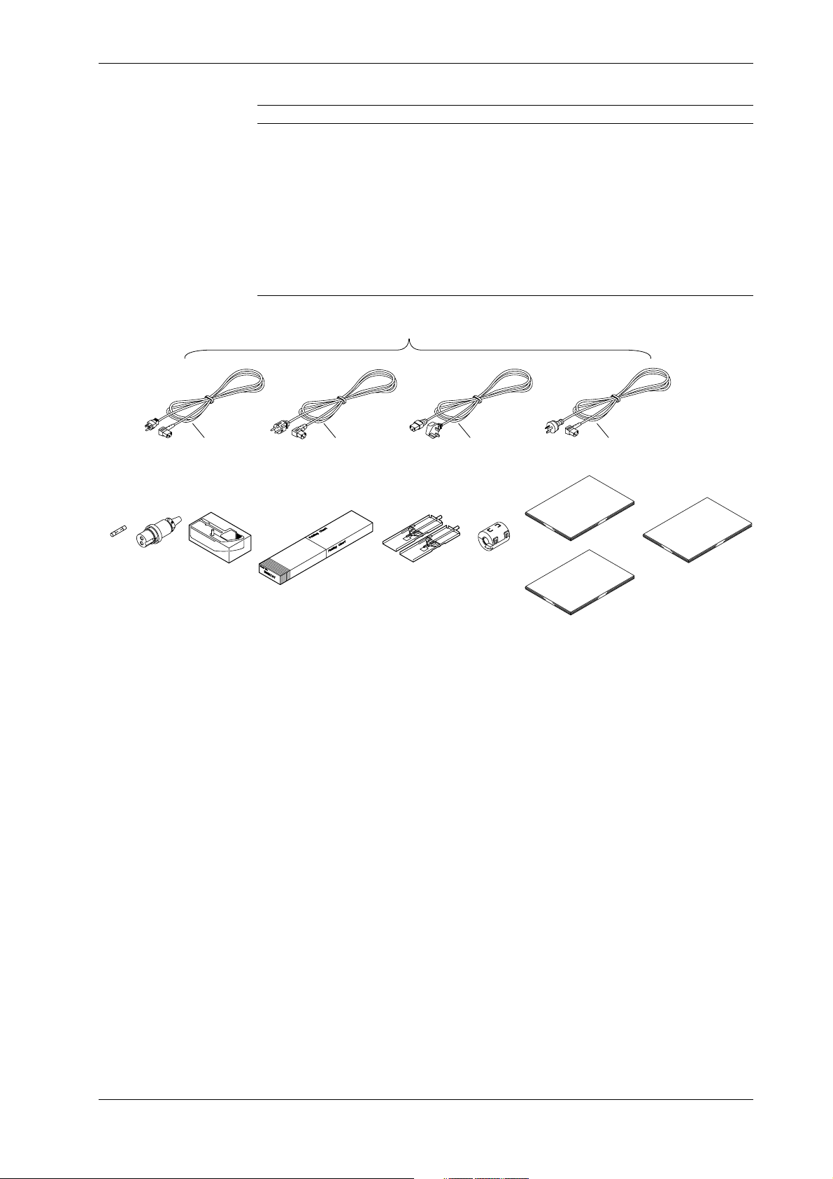
Standard Accessories
Checking the Contents of the Package
Name Part No. Q’ty Description
1. Power cord see page 2, 3 1
2. Fuse A1350EF 1 Timelag 2.5A 250V, for DR232/242, in case of
3. DC power supply A1105JC 1 Only for the subunit models whose power supply
terminal connector code is “-2”
4. Ribbon cassette B9627AZ 1 10 colors (for DR232/242)
5. Chart paper B9627AY 1 Length: 30m, 25mm grid (for DR232/DR242)
6. Mounting brackets B9900CW 1 x 2 for DR242
7. Clamp filter A1197MN 1 When power supply code is -1
8. User’s Manual IMDR232-01E 1 this manual (for DR232/242)
9. User’s Manual IMDR231-11E 1 Communication Interface manual (for DR232/242)
10.
Data acquisition software
1.One of these power cord types is supplied according
to the instrument's suffix code
DP120-13 Only for models whose software code is “-2”
DR232 located in fuse holder
D
2. 4.3. 5.
F
6. 7.
S
8.
9.
R
10.
IM DR232-01E
5
Page 7

Checking the Contents of the Package
Optional Accessories
Name Model Description
Extender module DV100-011
Extender base DV100-012
Extension cable DV200-000 Length: 0.5m
Extension cable DV200-001 Length: 1m
Extension cable DV200-002 Length: 2m
Extension cable DV200-005 Length: 5m
Extension cable DV200-010 Length: 10m
Extension cable DV200-020 Length: 20m
Extension cable DV200-050 Length: 50m
Extension cable DV200-100 Length: 100m
Extension cable DV200-200 Length: 200m
Extension cable DV200-300 Length: 300m
Extension cable DV200-400 Length: 400m
Extension cable DV200-500 Length: 500m
Shunt resistance DV300-011 10Ω, for screw
Shunt resistance DV300-012 10Ω, for clamp
Shunt resistance DV300-101 100Ω, for screw
Shunt resistance DV300-102 100Ω, for clamp
Shunt resistance DV300-251 250Ω, for screw
Shunt resistance DV300-252 250Ω, for clamp
Rack mount kit DV400-011 for DS400/600
Rack mount kit DV400-013 for DR232
Power cable DV400-051 between DR232/242 and DS400/600
Strain conversion cable DV450-001
Cable adapter DV250-001 For expanding cable
AC adapter DV500-001 2-pin inlet w/UL, CSA cable (Part No. B9988YA) for
AC adapter DV500-002 2-pin inlet w/VDE cable (Part No. B9988YB) for
AC adapter DV500-003 2-pin inlet w/SAA cable (Part No. B9988YC) for
AC adapter DV500-004 2-pin inlet w/BS cable (Part No. B9988YD) for
DC100/DA100/DS400/DS600 DC power supply model
DC100/DA100/DS400/DS600 DC power supply model
DC100/DA100/DS400/DS600 DC power supply model
DC100/DA100/DS400/DS600 DC power supply model
Optional Software
Spares
Name Model Description
DAQ 32 DP120-13 Windows 95/98 and Windows NT
DAQ 32 Plus DP320-13 Windows 95/98 and Windows NT
Name Part No. Min. Q’ty Description
Ribbon cassette B9627AZ 1 10 colors
Chart paper B9627RY 10 Length 30 m, grid 10mm
B9627AY 10 Length 30 m, grid 25mm
6
IM DR232-01E
Page 8
Safety Precautions
This instrument is an IEC safety class I instrument (provided with terminal for protective
grounding).
The following general safety precautions must be observed during all phases of operation, service
and repair of this instrument. If this instrument is used in a manner not sepecified in this manual,
the protection provided by this instrument may be impaired. Also, YOKOGAWA Electric
Corporation assumes no liability for the customer’s failure to comply with these requirements.
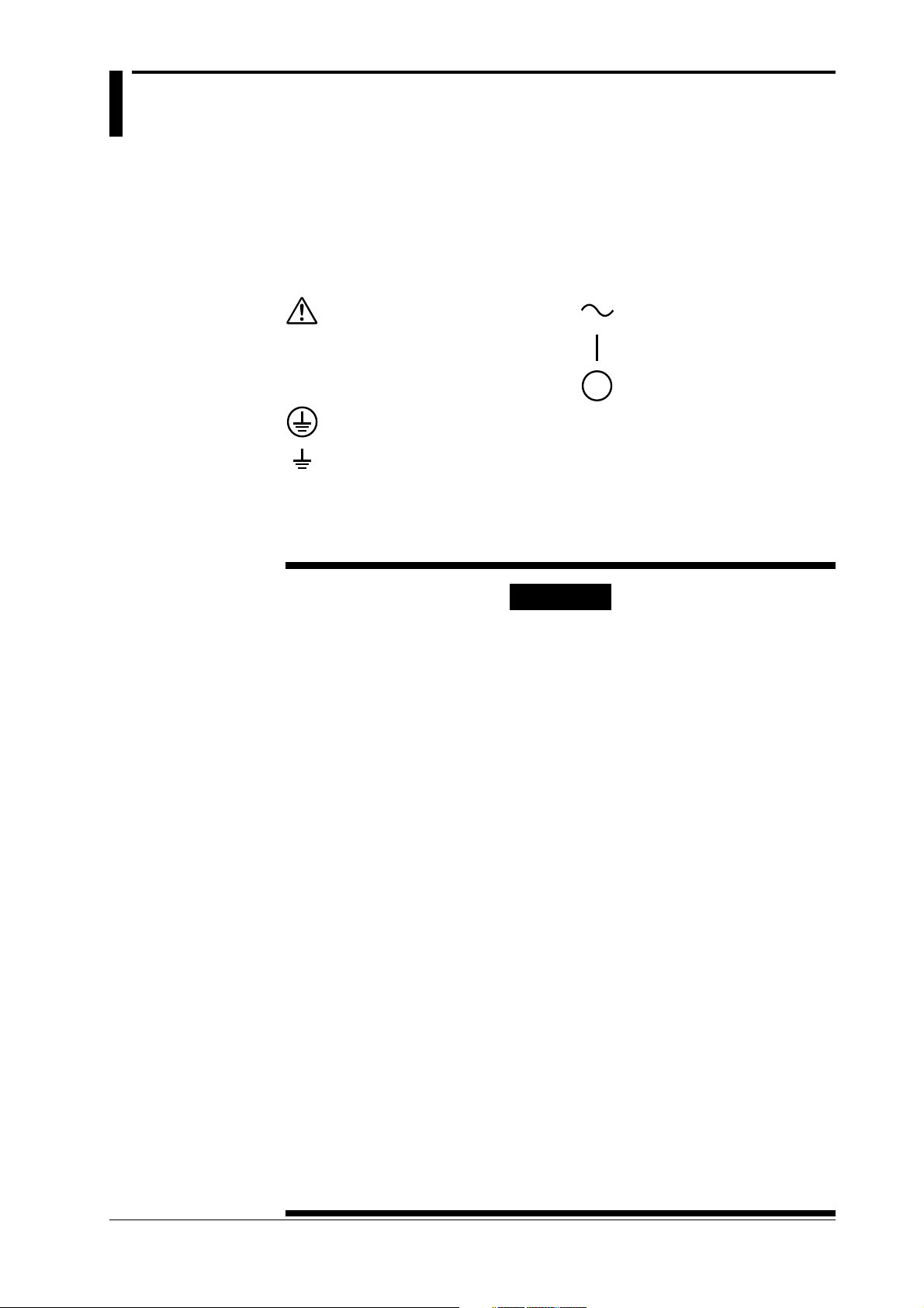
The following symbols are used on this instrument.
To avoid injury, death of personnel
or damage to the instrument, the
operator must refer to an explanation
in the User’s Manual or Service
Manual.
Protective grounding terminal.
Function grounding terminal. This
terminal should not be used as a
“Protective grounding terminal”.
Make sure to comply with the following safety precautions. Not complying might
result in injury, death of personnel or damage to the instrument.
Alternating current.
ON(power).
OFF(power).
WARNING
Power Supply
Ensure the source voltage matches the voltage of the power supply
before turning ON the power.
Power Cord and Plug
To prevent an electric shock or fire, be sure to use the power cord
supplied by YOKOGAWA. The main power plug must be plugged in an
outlet with protective grounding terminal. Do not invalidate protection by
using an extension cord without protective grounding.
Protective Grounding
Make sure to connect the protective grounding to prevent an electric
shock before turning ON the power.
Necessity of Protective Grounding
Never cut off the internal or external protective grounding wire or
disconnect the wiring of protective grounding terminal. Doing so poses a
potential shock hazard.
Defect of Protective Grounding and Fuse
Do not operate the instrument when protective grounding or fuse might be
defective.
Do not Operate in an Explosive Atmosphere
Do not operate the instrument in the presence of flammable liquids or
vapors. Operation of any electrical instrument in such an environment
constitutes a safety hazard.
Fuse
To prevent a fire, make sure to use fuses with specified standard(current,
voltage, type). Before replacing the fuse, turn OFF the power and
disconnect the power source. Do not use a different fuse or short-circuit
the fuse holder.
Do not Remove any Covers
There are some areas with high voltages. Do not remove any cover if the
power supply is connected. The cover should be removed by qualified
personnel only.
External Connection
To ground securely, connect the protective grounding before connecting
to measurement or control unit.
IM DR232-01E
7
Page 9

How to Use this Manual
This User’s Manual consists of the following twelve chapters and Index.
Chapter Title Description
Chapter 1 System Configuration Explains the position of the DR within DARWIN, its
Chapter 2 Functions Explains the functions of the DR. Operating
Chapter 3 Installation and Wiring Describes cautions for use, explains how to install and
Chapter 4 Setting the Monitor Mode Explains the display in the monitor mode.
Display
Chapter 5 Setting the Input Type/ Explains the operations when setting the input type,
Recording Span/ recording span and linear scaling function.
Linear Scaling
Chapter 6 Setting the Recording Explains the operations when setting recording
Conditions conditions such as the recording mode, channels,
Chapter 7 Executing Recording Explains how to start and stop recording.
Chapter 8 Setting, Displaying and Explains how to set an alarm and what to do when an
Recording Alarms alarm occurs.
Chapter 9 Event/Action Function and Explains how to operate the event/action function,.
Other Functions how to copy recording information, how to reset
Chapter 10 Basic Settings (SET UP) Explains functions which usually do not need to be
Chapter 11 Saving/Reading Measured, Explains how to save measured data, computed data
Computed and Set-up Data and set-up data to the internal RAM disk or floppy
Chapter 12 Executing Computation Explains the computation function (optional).
(Available with the /M1 Model)
Chapter 13 Trouble-Shooting and Explains maintenance procedures, error messages and
Maintenance calibration procedures.
Chapter 14 Specifications Explains specifications for all features of DR.
Index Gives the index in main menu and alphabetic order.
configuration, etc..
procedures are not explained here.
wire the DR, the power cord, how to switch ON/OFF
the DR, how to set the date/time, explains the noise
filter, etc..
recording interval, chart speed, recording span, and
recording format.
alarms, how to reset the timer, how to use the keylock, and how to use the external in-/output function.
changed, and how to set
disk and read them into the instrument.
8
IM DR232-01E
Page 10
Conventions Used in this Manual
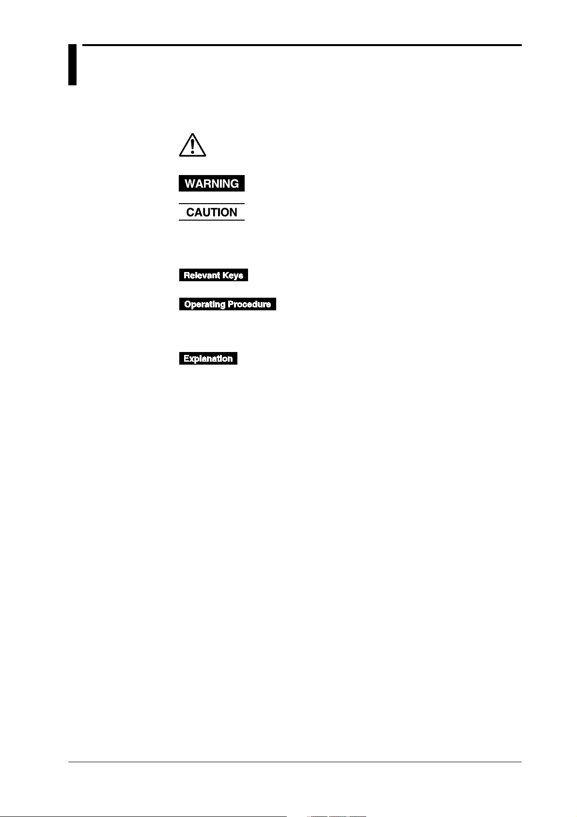
Used Symbols
The following symbol marks are used to attract the operator’s attention.
Affixed to the DR232/242, indicating that for safety, the operator should
refer to the appropriate User’s Manual. For a list of the User’s Manuals,
refer to page 1.
Describes precautions that should be observed to prevent the danger of
injury or death to the user.
Describes precautions that should be observed to prevent damage to the
DR232/242.
Note
Provides information that is important for proper operation of the DR232/
242.
Indicates the relevant panel keys and indicators to carry out
the operation.
The procedure is explained by a flow diagram. For the
meaning of each operation, refer to the example below. The
operating procedures are given with the assumption that you
are not familiar with the operation. Thus, it may not be
necessary to carry out all the steps when changing settings.
Describes settings and restrictions relating to the operation.
IM DR232-01E
9
Page 11

Contents
Foreword .................................................................................................................................................................................. 1
Checking the Contents of the Package ..................................................................................................................... 3
Safety Precautions .............................................................................................................................................................. 7
How to Use this Manual .................................................................................................................................................... 8
Conventions Used in this Manual ................................................................................................................................9
List of Menus and Set-up Data .................................................................................................................................... 13
Chapter 1 System Configuration
1.1 About DARWIN ................................................................................................................................... 1-1
1.2 Product Overview .................................................................................................................................1-2
1.3 Names of Parts ...................................................................................................................................... 1-4
1.4 Floppy Disk ........................................................................................................................................ 1-11
Chapter 2 Functions
2.1 Display Functions .................................................................................................................................2-1
2.2 Measurement Input Functions .............................................................................................................. 2-3
2.3 Recording Functions ............................................................................................................................. 2-5
2.4 Alarm Function ................................................................................................................................... 2-13
2.5 Standard Computation Functions ....................................................................................................... 2-16
2.6 Other Functions .................................................................................................................................. 2-17
Chapter 3 Installation and Wiring
3.1 General Precautions for Installation ..................................................................................................... 3-1
3.2 How to Install ....................................................................................................................................... 3-2
3.3 How to Connect the Input/Output Modules ......................................................................................... 3-7
3.4 Installing the Chart and Ribbon Cassette ............................................................................................. 3-9
3.5 Connecting the Interface Cables ......................................................................................................... 3-14
3.6 Connecting the Extension Cables- ......................................................................................................3-19
3.7 Connecting the Signal Lines ............................................................................................................... 3-20
3.8 Connecting an Extension Module to Extension Bases .......................................................................3-28
3.9 Connecting the Power Cord and Turning the Power ON/OFF ...........................................................3-30
3.10 Setting the Date and Time .................................................................................................................. 3-35
3.11 Countering Noise................................................................................................................................3-36
Chapter 4 Setting the Monitor Mode Display
4.1 Using the AUTO Display......................................................................................................................4-1
4.2 Using the MANUAL Display ...............................................................................................................4-4
4.3 Using the PAGE Display ...................................................................................................................... 4-6
4.4 Using the ALARM SEARCH Display .................................................................................................4-7
4.5 Using the BARGRAPH Display...........................................................................................................4-9
4.6 Using the ALARM STATUS Display.................................................................................................4-10
4.7 Using the RELAY STATUS Display .................................................................................................. 4-11
4.8 Using the CLOCK (Data & Time) Display ........................................................................................ 4-13
Chapter 5 Setting the Input Type/Recording/Span/Linear Scalling
5.1 Setting the Type of Input and Recording Span .....................................................................................5-1
5.2 Setting Linear Scaling and the Recording Span ................................................................................... 5-4
5.3 Configuring the Input Range and Recording Span or the Linear Scaling of a Power Monitoring
Channel .................................................................................................................................................5-6
5.4 Configuring the Measuring Range and Recording Span or the Linear Scaling of a Strain Input
Channel ...............................................................................................................................................5-10
10
IM DR232-01E
Page 12

5.5 Performing Initial Balancing/Initialization on a Strain Input Channel...............................................5-12
5.6 Configuring the Pulse Input Channel ................................................................................................. 5-13
Chapter 6 Setting the Recording Conditions
6.1 Setting the Recording Mode, Engineering Unit, Recording Channel and Recording Interval ............ 6-1
6.2 Setting the Chart Speed ........................................................................................................................ 6-4
6.3 Setting Recording Zones and Partially Expanded Recording .............................................................. 6-6
6.4 Setting Tag, Digital Printout and Manual Printout ............................................................................... 6-8
6.5 Setting the Alarm Printout ..................................................................................................................6-10
6.6 Setting Scale Printout, List Printout and List Format .........................................................................6-12
6.7 Entering Messages, Headers and Title................................................................................................6-14
6.8 Setting Match Time, Moving Average, Interpolation and Groups...................................................... 6-16
Contents
1
2
3
Chapter 7 Executing Recording
7.1 Starting Dot Printing, Digital Printing and Printing in Logging Mode ................................................7-1
7.2 Starting Manual Printing, List Printing and Header Printing ............................................................... 7-2
7.3 Starting Message Printing .....................................................................................................................7-3
7.4 Printing Set-up Lists .............................................................................................................................7-4
Chapter 8 Setting, Displaying and Recording Alarms
8.1 Setting Alarms and Relays (including internal switches) .....................................................................8-1
8.2 Alarm Display and Printing ..................................................................................................................8-4
Chapter 9 Event/Action Function and Other Functions
9.1 Setting Event/Action Functions ............................................................................................................ 9-1
9.2 Copying .............................................................................................................................................. 9-12
9.3 Alarm Acknowledgment, Alarm Reset, Timer Reset, Keylock, and Message Printout .....................9-14
9.4 Clearing Alarm/Message Buffers, Displaying Module/Communications Information, Structuring
System Modules, and Initializing Information ...................................................................................9-16
9.5 Fail/Chart End Output, and Remote Control Signal Input ................................................................. 9-18
9.6 Summer/Winter Time ......................................................................................................................... 9-19
Chapter 10 Basicn Settings (SET UP)
10.1 Selecting Adjustment of Dot-Printing Position or Scan Interval........................................................10-1
10.2 Setting Recording Format................................................................................................................... 10-3
10.3 Select Alarm Interval/Hysteresis/Hold/A/D Converter Integration Time/Filter ................................. 10-7
10.4 Setting Operation Mode of Relay/Internal Switch .............................................................................10-9
10.5 Setting Burn-out/Reference Junction Compensation ....................................................................... 10-12
10.6 Setting Recording Colors.................................................................................................................. 10-14
10.7 Setting Key Lock .............................................................................................................................. 10-15
10.8 Setting FUNC/FUNC3 Menu ........................................................................................................... 10-17
10.9 Setting SET/SET3 Menu ..................................................................................................................10-20
10.10 Selecting Display Update Interval, Registering Details Set/Selected with SET UP Menu, and
Terminating SET UP Menu .............................................................................................................. 10-24
10.11 Selecting the temperature unit from °C or °F (option) ..................................................................... 10-25
10.12 Working with the Report Function ................................................................................................... 10-27
Chapter 11 Saving/Reading Measured, Computed and Set-up Data
11.1 Saving Measured and Computed Data ............................................................................................... 11-1
11.2 Reading Measured and Computed Data .............................................................................................11-7
11.3 Saving Set-up Data ........................................................................................................................... 11-10
11.4 Reading Set-up Data......................................................................................................................... 11-12
11.5 Copying a Data File.......................................................................................................................... 11-15
11.6 Copying in ASCII Format.................................................................................................................11-17
IM DR232-01E
4
5
6
7
8
9
10
11
12
13
14
Index
11
Page 13

Contents
11.7 Deleting a Data File.......................................................................................................................... 11-20
11.8 Displaying RAM Disk and Floppy Disk Information ...................................................................... 11-21
11.9 Initializing the RAM Disk ................................................................................................................ 11-23
11.10 Formatting a Floppy Disk .................................................................................................................11-24
Chapter 12 Executing Computation (Available with the /M1 Model)
12.1 Overview of the Computation Function .............................................................................................12-1
12.2 Setting a Computation Equation.........................................................................................................12-4
12.3 Setting a Constant...............................................................................................................................12-7
12.4 Starting/Stopping Computation .......................................................................................................... 12-8
12.5 Setting Actions to be Carried out in Case of Computation Error and Setting the Time Axis for TLOG
SUM..................................................................................................................................................12-12
Chapter 13 Trouble-shooting and Maintenance
13.1 Periodic Maintenance and Recommended Parts Replacement Period ...............................................13-1
13.2 Replacing the Fuse.............................................................................................................................. 13-2
13.3 Troubleshooting ..................................................................................................................................13-3
13.4 Error Codes.........................................................................................................................................13-4
13.5 Calibration ..........................................................................................................................................13-6
Chapter 14 Specifications
14.1 Specifications of DR232/DR242 and DS400/DS600.........................................................................14-1
14.2 Universal Input Module and DCV/TC/DI Input Module .................................................................14-11
14.3 Specifications of mA-input Module .................................................................................................14-14
14.4 Specifications of Power Monitor Module ........................................................................................ 14-16
14.5 Specifications of Strain Input Module..............................................................................................14-20
14.6 Specifications of Pulse Input Module............................................................................................... 14-22
14.7 Specifications of Digital Input Module ............................................................................................14-24
14.8 Alarm Module................................................................................................................................... 14-26
14.9 DI/DO Module.................................................................................................................................. 14-27
14.10 Communication Interface Module ....................................................................................................14-29
14.11 Specifications of Extension Module and Extension Base ................................................................ 14-32
14.12 Dimensional Drawings ..................................................................................................................... 14-33
INDEX
12
IM DR232-01E
Page 14

List of Menus and Set-up Data
The following is a list of set-up data, procedures to switch to different setting modes, and setting
menu.
Measurement Condition Settings
Parameters Procedure Selecting menu Reference
Input type, span, linear RANGE key 001-01:VOLT/2V Chapter 5
1
Chart Speed Settings
Recording Settings
scaling*
Units SET key*
Moving average
Measurement cycle*
A/D integration time*1Turn ON power while pressing the DISP key
1
Filter*
*1: Make sure that the total number of setting changes, including calibrations and restructuring, does not
surpass 100000.
*2: Procedure varies according to the menu configuration of the SET key (see section 10.9).
Parameters Procedure Selecting menu Reference
Chart speed 1 CHART key CHART Section 6.2
Chart speed 2
*: Procedure varies according to the menu configuration of the SET key (see section 10.9).
Press the SET key for about three seconds
1
Turn ON power while pressing the DISP key
Turn ON power while pressing the DISP key
Press the SET key for about three seconds*
2
SET=UNIT Section 6.1
*2SET=MOVE AVE Section 6.8
SET UP= Section 10.1
SCAN INTVL
SET UP=A/D INTG Section 10.3
SET UP=FILTER Section 10.3
SET=CHART2 Section 6.2
Display Settings
Parameters Procedure Selecting menu Reference
Logging/Analog trend SET key* SET=SYSTEM Section 6.1
switch, dot-printing cycle
Recording channel SET key* SET=TREND Section 6.1
Recording zone
Partial compression
Tag
Channel to digital print,
number of rows to print
Channel to manual print
Alarm print
Channel to print scale
values
Channel to list print
Items to list print
Message
Header
Title
Interpolation
Adjust dot-printing
position
Recording format
Dot-print color
*: Procedure varies according to the menu configuration of the SET key (see section 10.9).
Parameters Procedure Selecting menu Reference
Switch display DISP key and MODE key -------- Chapter 4
Display update interval Turn ON power while pressing the SET UP=DISPLAY Section 10.10
Press the SET key for about three seconds*
Press the SET key for about three seconds*
Press the SET key for about three seconds*
Press the SET key for about three seconds*
Press the SET key for about three seconds*
Press the SET key for about three seconds*
Press the SET key for about three seconds*
Press the SET key for about three seconds*
Press the SET key for about three seconds*
Press the SET key for about three seconds*
Press the SET key for about three seconds*
Press the SET key for about three seconds*
Press the SET key for about three seconds*
Turn ON power while pressing the DISP key
Turn ON power while pressing the DISP key
Turn ON power while pressing the DISP key
DISP key
SET=ZONE Section 6.3
SET=PERTIAL Section 6.3
SET=TAG Section 6.4
SET=DIGITAL PR Section 6.4
SET=MANUAL PR Section 6.4
SET=ALARM PR Section 6.5
SET=SCALE PR Section 6.6
SET=LIST PR Section 6.6
SET=LIST FMT Section 6.6
SET=MESSAGE Section 6.7
SET=HEADER Section 6.7
SET=TITLE Section 6.7
SET=INTERPOL Section 6.8
SET UP=PRN ADJ Section 10.1
SET UP=RECORD Section 10.2
SET UP=COLOR Section 10.6
Alarm Settings
IM DR232-01E
Parameters Procedure Selecting menu Reference
Alarm, alarm output ALARM key 001-01:1/OFF Section 8.1
relay
Alarm
interval/hysteresis/hold
Execute alarm FUNC key* ALARM ACK Section 9.3
acknowledge
Reset alarm FUNC key* ALARM RST Section 9.3
Clear alarm buffer
*: Procedure varies according to the menu configuration of the FUNC key (see section 10.8).
Turn ON power while pressing the DISP key
Press the FUNC key for about three seconds*
SET UP=ALARM Section 10.3
ALM BUF CLEAR Section 9.4
13
Page 15

List of Menus and Set-up Data
Computation Settings
Parameters Procedure Selecting menu Reference
Computation equation SET key* SET=MATH Section 12.2
Constant SET key* SET=CONST Section 12.3
Perform computation FUNC key** MATH START Section 12.4
Clear measured data and FUNC key** MATH CLR START Section 12.4
perform computation
Stop computation FUNC key** MATH STOP Section 12.4
Clear incomplete FUNC key** MATH ACK Section 12.4
measurement status
Handling of computation
error/time axis setting of
TLOG SUM
*: Procedure varies according to the menu configuration of the SET key (see section 10.9).
**: Procedure varies according to the menu configuration of the FUNC key (see section 10.8).
Turn ON power while pressing the DISP key
Settings for Saving/Loading Measured/Setup Data (Floppy Disk)
Parameters Procedure Selecting menu Reference
Save/Load measured data SET key* SET=MEMORY
Save/Load set-up data SET key* SET=FLOPPY
of SET mode
Copy measured data SET key* SET=MEMORY Section 11.5
between built-in RAM
disk and floppy disk
Convert data and copy SET key* SET=MEMORY Section 11.6
Initialize built-in RAM SET key* SET=MEMORY Section 11.9
disk
Initialize floppy disk SET key* SET=MEMORY Section 11.10
Save/Load set-up data Turn ON power while pressing the DISP SET UP=FLOPPY
of SET UP mode key
*: Procedure varies according to the menu configuration of the SET key (see section 10.9).
SET UP=MATH Section 12.5
Section 11.1, 11.2
Section 11.2, 11.3
Section 11.3, 11.4
Perform Printing
Other Settings
14
Parameters Procedure Selecting menu Reference
Perform manual print PRINT key MAN PR START Section 7.2
Perform list print PRINT key LIST START Section 7.2
Perform header print PRINT key HEADER START Section 7.2
Perform message print FUNC key* MSG PRINT Section 7.3
Perform setup list print
*: Procedure varies according to the menu configuration of the FUNC key (see section 10.8).
Parameters Procedure Selecting menu Reference
Timer SET key* SET=TIMER Section 6.1
Event/Action SET key* SET=LOGIC Section 9.1
Copy between channels SET key* SET=COPY Section 9.2
Match time
Group
Relay, internal switch
operation mode
Burnout
Reference junction
compensation
Key lock
Menu configuration
of FUNC key FUNC PARM
Menu configuration
of SET key
Report function
Reset timer FUNC key** TIMER RESET Section 9.3
Lock keys FUNC key** KEY LOCK ON Section 9.3
Start report FUNC key** REPORT START Section 10.12
Stop report FUNC key** REPORT STOP Section 10.12
Start report print FUNC key** REPORT RECALL Section 10.12
Stop report print FUNC key** REPORT PRINT Section 10.12
Clear message buffer
Display module settings
Display communication
settings
Initialize setting
information
*: Procedure varies according to the menu configuration of the SET key (see section 10.9).
**: Procedure varies according to the menu configuration of the FUNC key (see section 10.8).
Press the FUNC key for about three seconds*
Press the SET key for about three seconds*
Press the SET key for about three seconds*
Turn ON power while pressing the DISP key
Turn ON power while pressing the DISP key
Turn ON power while pressing the DISP key
Turn ON power while pressing the DISP key
Turn ON power while pressing the DISP key
Turn ON power while pressing the DISP key
Turn ON power while pressing the DISP key
Press the FUNC key for about three seconds**
Press the FUNC key for about three seconds**
Press the FUNC key for about three seconds**
Press the FUNC key for about three seconds**
S/U LIST START Section 7.4
SET=MATCH TIME Section 6.8
SET=GROUP Section 6.8
SET UP=RELAY Section 10.4
SET UP=BURN OUTSection 10.5
SET UP=RJC Section 10.5
SET UP=LOCK Section 10.7
SET UP= Section 10.8
SET UP=SET PARM Section 10.9
SET UP=REPORT Section 10.12
START
START
MSG BUF CLEAR Section 9.4
MODULE INF Section 9.4
COMM INF Section 9.4
RAM INIT Section 9.4
IM DR232-01E
Page 16
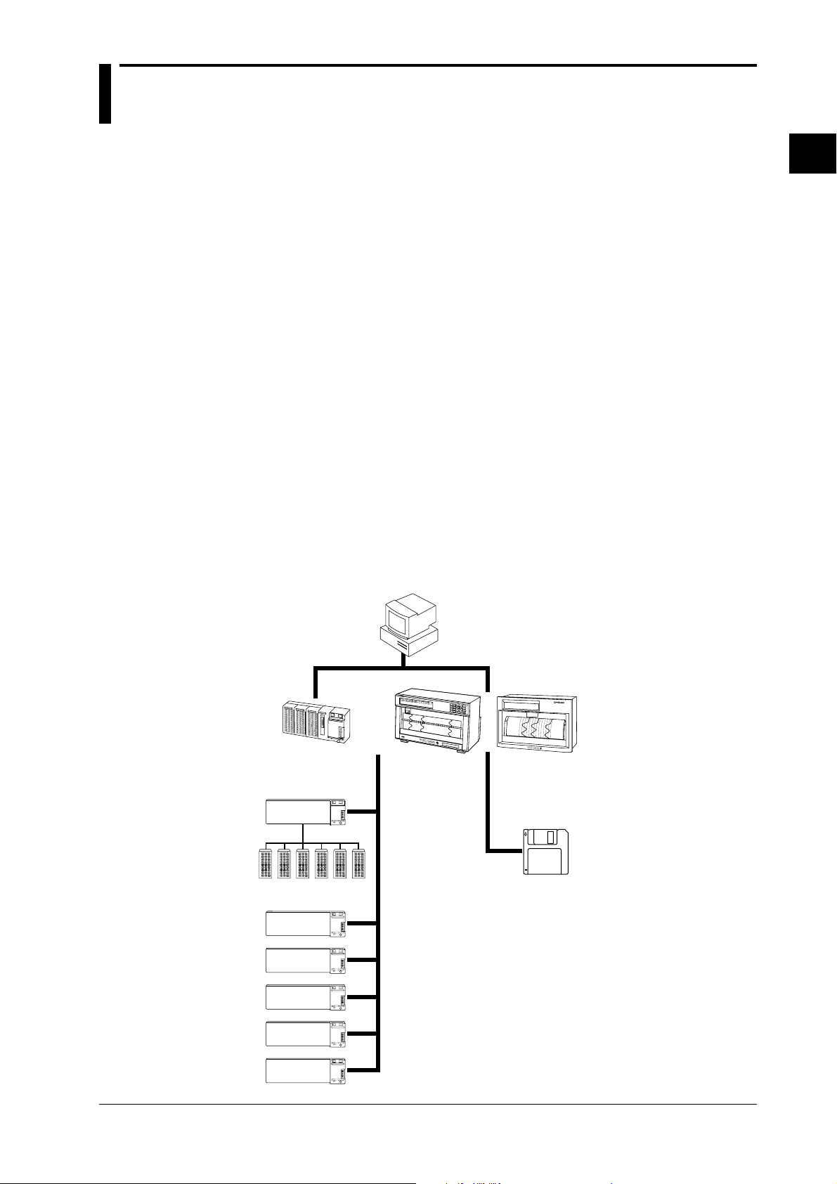
1.1 About DARWIN
Created from a completely new concept that is based on modular architecture, this group of next
generation data acquisition systems is called DARWIN (Data Acquistion and Recording
Windows).
Today many data acquisition networks are increasingly being linked together. More than ever
before, large volume, high speed, accurate, easy-to-use communication functions are essential in
many disciplines.
In the world of measurement and control where the number of measurement points has increased
sharply, the ability to acquire information from a large number of points easily and economically
is crucial. Interfacing to a personal computer allows simplified utilization of the information
while improving quality and efficiency.
DARWIN is based on a unique, new concept to meet these needs. The art of measurement is
revolutionized by DARWIN which integrates functions of conventional recording and data
logging.
Most existing data acquisition equipment has been the all-in-one type in which the measurement
section and display/recording section are contained in one box. While this simplifies operation on
the one hand, it is difficult to adapt to changes in the measurement environment and also makes
expansion difficult.
DARWIN uses a data acquisition engine and remote I/O modules which are completely separate
from each other. It is an entirely new product line which quickly and flexibly copes with various
restrictive conditions and changes in specifications.
Supported by a personal computer, a whole line-up can be created starting with the data
acquisition systems DA series which performs data logging. For example, using a printer as the
output device, the equipment becomes a hybrid recorder (DR series).
Two models are available in the DR series: the DR230 and DR240. The DR 230 is a desk-top
hybrid recorder, and the DR240 is a panel-mount hybrid recorder (component type).
1
System Configuration
Personal
computer
DA100
Subunit
Input/output
modules
D
Extension cables
(max. length 500m)
CH=001 RANGE=TC TYPE-T
0
0
1
0
0
6
0
0
2
0
1
1
0
0
7
0
0
3
0
1
2
0
0
8
0
0
4
0
1
3
0
0
9
0
0
5
0
1
4
0
1
0
0
1
5
DR240DR230
0
1
6
0
1
7
0
1
8
0
1
9
0
2
0
FD
H
y
b
r
i
d
R
e
c
o
r
d
e
r
0
2
1
0
2
6
0
2
2
0
2
7
0
2
3
0
2
8
0
2
4
0
2
9
0
2
5
0
3
0
IM DR232-01E
1-1
Page 17

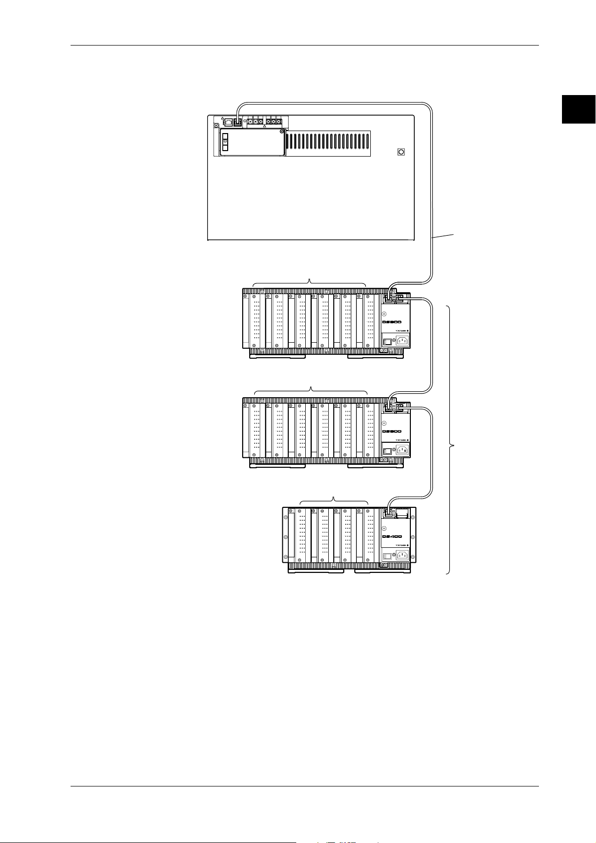
1.2 Product Overview
This product is a hybrid recorder which can record and measure from small-scale 10-ch data up to
widely distributed 300-ch multi-point data.
The number of measurement points can be expanded up to a maximum of 300-ch by connecting
up to six subunits (DS400/DS600) to a main unit (DR232/242). Using dedicated extension cables
between units, interconnections can be extended up to 500 m. Since measured objects scattered
over a wide area can be wired fast and with a minimum of wiring, a flexible, extensive
measurement system can be configured. The input modules to be incorporated in the DR232/242
or DS400/600 can be selected from the following, to suit your measurement conditions:
• Universal input module and DCV/TC/DI input module
Temperature, DC voltage and contact signals can be measured, but cannot be connected to the
main unit.
• mA-input Module
This module can directly measure DC currents ranging from -20 mA to 20 mA since it contains
shunt resistors. It cannot be connected to a system's main unit.
• Power Monitor Module
This module can measure the effective voltage, effective current, active power, reactive power,
apparent power, frequency, power factor and phase angle for an AC voltage or AC current input.
It is available in either a single-phase or three-phase model. This module cannot be connected to
a system's main unit.
• Strain Input Module
This module can measure strain. It is available in either a model with built-in 120- or 350-Ω
bridge resistors or a model with NDIS terminals where bridge resistors are connected externally.
The module cannot be connected to a system's main unit.
• Pulse Input Module
This module can measure pulses. It cannot be connected to a system's main unit.
• Digital input module
This module can measure contact signals. It cannot be connected to a system’s main unit.
• Communication interface module
This module is necessary when communicating with a personal computer. Measurement
conditions can be set and data acquired via the communication interface (GP-IB, RS-232-C, etc.)
of this dule. This module can only be connected to the main unit.
• Alarm module
This module can output alarm signals as contact signals. The module can be connected to the
main unit or the subunit.
• DI/DO module
This module allows a signal to be output in the case of alarm, failure, or chart end and a remote
control signal for the product to be input. The module can be connected to the main unit or the
subunit but only one module in all units.
1-2
Note
When the following handling is done, it is necessary to carry out “system construction” to operate the
instrument correctly. After executing system construction, confirm the module information. For details,
see page 9-16.
• Connection (including addition or replacement)/removal of subunits, or unit number setting (see page 3-
7)
• Mounting (including addition or replacement)/removal of modules
IM DR232-01E
Page 18
Connection example
CH
1
CH
2
CH
3
CH
4
CH
5
CH
6
CH
7
CH
8
CH
9
CH
10
b -/B +/A
CH
1
CH
2
CH
3
CH
4
CH
5
CH
6
CH
7
CH
8
CH
9
CH
10
b-/B+/A
CH
1
CH
2
CH
3
CH
4
CH
5
CH
6
CH
7
CH
8
CH
9
CH
10
b-/B+/A
CH
1
CH
2
CH
3
CH
4
CH
5
CH
6
CH
7
CH
8
CH
9
CH
10
b-/B+/A
CH
1
CH
2
CH
3
CH
4
CH
5
CH
6
CH
7
CH
8
CH
9
CH
10
b-/B+/A
CH
1
CH
2
CH
3
CH
4
CH
5
CH
6
CH
7
CH
8
CH
9
CH
10
b -/B +/A
CH
1
CH
2
CH
3
CH
4
CH
5
CH
6
CH
7
CH
8
CH
9
CH
10
b -/B +/A
CH
1
CH
2
CH
3
CH
4
CH
5
CH
6
CH
7
CH
8
CH
9
CH
10
b-/B+/A
CH
1
CH
2
CH
3
CH
4
CH
5
CH
6
CH
7
CH
8
CH
9
CH
10
b-/B+/A
CH
1
CH
2
CH
3
CH
4
CH
5
CH
6
CH
7
CH
8
CH
9
CH
10
b -/B +/A
CH
1
CH
2
CH
3
CH
4
CH
5
CH
6
CH
7
CH
8
CH
9
CH
10
b-/B+/A
CH
1
CH
2
CH
3
CH
4
CH
5
CH
6
CH
7
CH
8
CH
9
CH
10
b -/B +/A
CH
1
CH
2
CH
3
CH
4
CH
5
CH
6
CH
7
CH
8
CH
9
CH
10
b -/B +/A
CH
1
CH
2
CH
3
CH
4
CH
5
CH
6
CH
7
CH
8
CH
9
CH
10
b -/B +/A
CH
1
CH
2
CH
3
CH
4
CH
5
CH
6
CH
7
CH
8
CH
9
CH
10
b-/B+/A
CH
1
CH
2
CH
3
CH
4
CH
5
CH
6
CH
7
CH
8
CH
9
CH
10
b-/B+/A
SUB UNIT
POWER
STATUS
POWER
STATUS
POWER
100-240V 50/60Hz 55VA MAX
STATUS
100-240V 50/60Hz 70VA MAX
SUB UNIT
100-240V 50/60Hz 70VA MAX
SUB UNIT
Subunit
DS600
Subunit
DS600
Subunit
DS400
Extension cable
10ch Universal Input module
10ch Universal Input module
10ch Universal Input module
Up to 6 subunits
can be connected
Main unit DR232/DR242
1.2 Product Overview
1
System Configuration
IM DR232-01E
1-3
Page 19
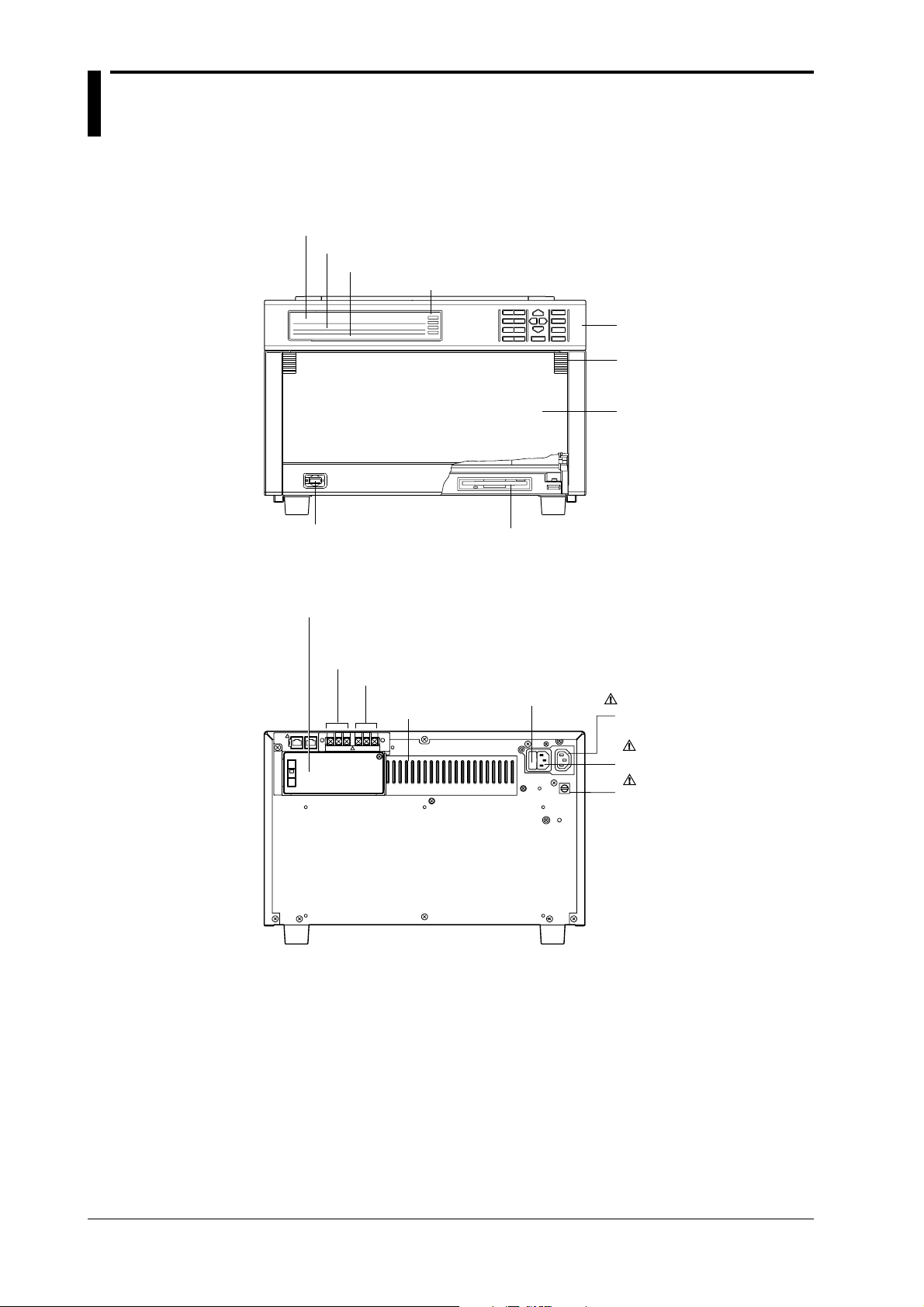
1.3 Names of Parts
DR232 Main Unit (desk-top hybrid recorder)
Front
Main display (See chapter 4.)
Sub-display 1 (See chapter 4.)
Sub-display 2 (See chapter 4.)
Status indicator
Operation panel
(See chapters 3 to 12.)
Handle to open/close
the front door
Front door
Power switch (See page 3-22)
Rear
Vacant slot with cover
(for communication interface,
alarm, or DI/DO modules)
Failure output terminals
Chart end output terminals
Heat sink fins
Floppy disk drive (Only for DR232-1)
Power fuse ( See page 13-2)
AC outlet(Au xiliary
for DS400/DS600
: See page 3-29)
Power connector
( See page 3-29)
Function grounding
terminal
1-4
IM DR232-01E
Page 20
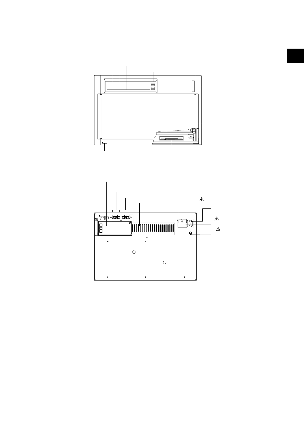
DR242 Main Unit (panel-mount hybrid recorder)
Main display (See chapter 4.)
Sub-display 1 (See chapter 4.)
Sub-display 2 (See chapter 4.)
Status indicator
Operation panel
(Located behind the front door.
See chapters 3 to 12.)
Handle to open/close
the front door
Front door
Power switch
(Located inside the front door. See page 3-22.)
Floppy disk drive (Only for /DR242-1)
Heat sink fins
Power terminals with a cover
( See page 3-30)
Vacant slot with cover
(for communication interface, alarm, or DI/DO modules)
Failure output terminals
Chart end output terminals
Power fuse (See page 13-2)
(located in the main unit)
Function grounding
terminal
AC outlet(Auxiliary
for DS400/DS600
: See page 3-30)
Front
1.3 Names of Parts
1
System Configuration
Rear
IM DR232-01E
1-5
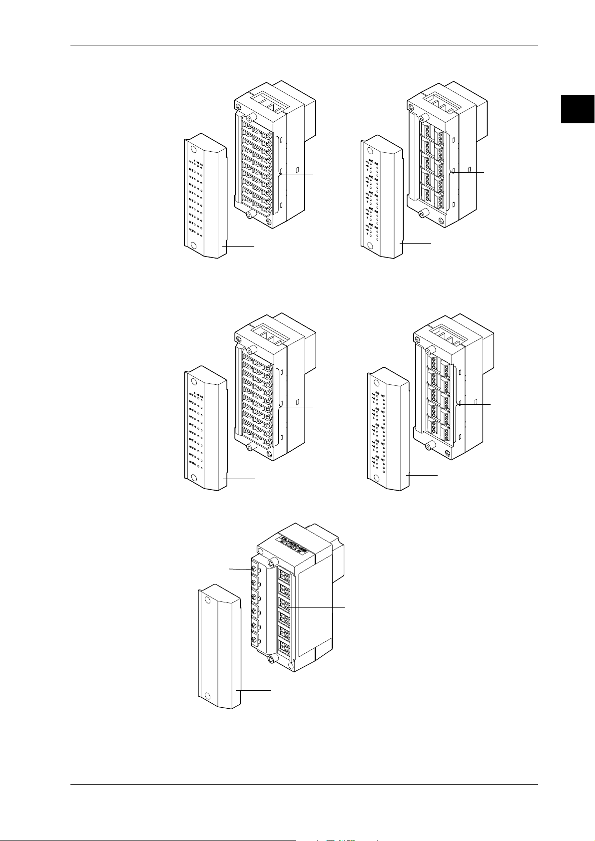
Page 21
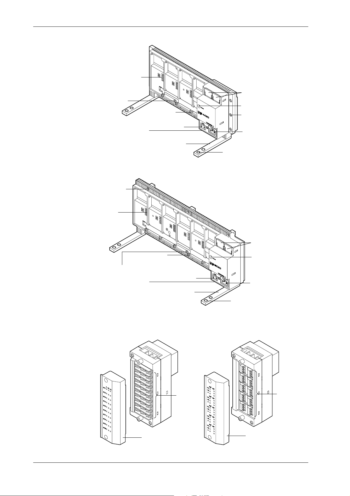
1.3 Names of Parts
Subunit DS400
Subunit DS600
Module connector
Switch to set the
unit number
Screw holes for
module installation
Function grounding
terminal (below power switch)
Installation
holes
Power switch
Lid covering the extension
cable connector
Status indicator
Installation holes
Power connector
Feet
Holes for fastening the feet
Input modules
Module
connector
Screw holes for
module installation
Switch to set
the unit number
Function grounding
terminal (below power switch)
Power switch
Feet
10-ch Universal input module (DU100-11/DU100-12)
DU100-11
DU100-12
Lid covering the
extension cable
connector
Status indicator
Power connector
Holes for fastening
the feet
1-6
Screw
terminal
Cover
The 20-ch Universal input modules (DU100-21/DU100-22) and the 30-ch Universal input modules
(DU100-31/DU100-31) are similar to the ones shown above.
Cover
Clamp
terminal
IM DR232-01E
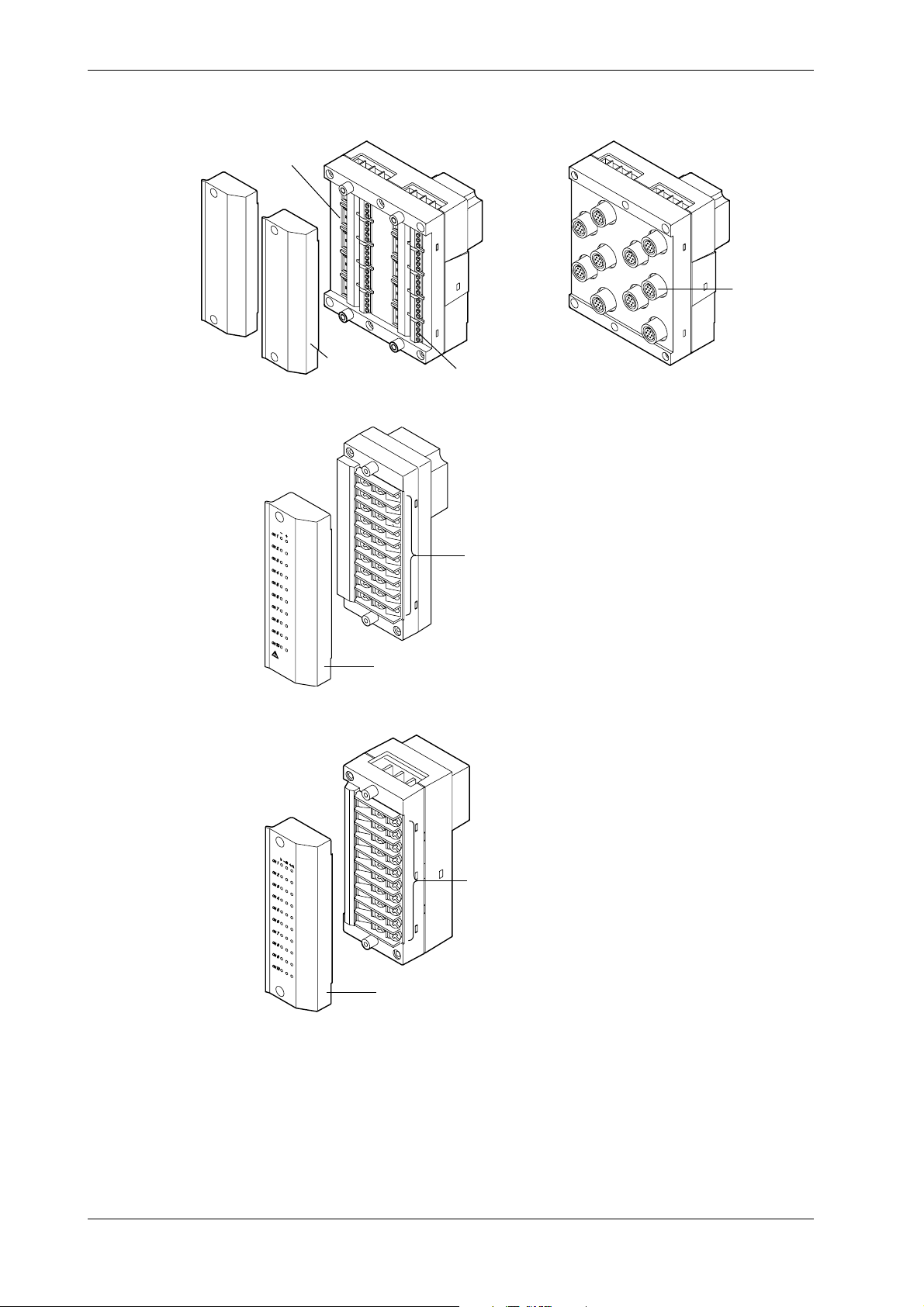
Page 22
10-ch DCV/TC/DI input module (DU200-11/DU200-12)
1.3 Names of Parts
DU200-11
Screw
terminal
Cover
The 20-ch DCV/TC/DI input modules (DU200-21/DU200-22) and the 30-ch DCV/TC/DI input modules
(DU200-31/DU200-31) are similar to the ones shown above.
DU200-12
Clamp
terminal
Cover
mA input module (DU300-11/DU300-12)
1
System Configuration
Cover
AC input module (DU400-12/22)
Wire clip
Cover
Screw
terminal
Clamp
terminal
Cover
Clamp terminal
IM DR232-01E
1-7
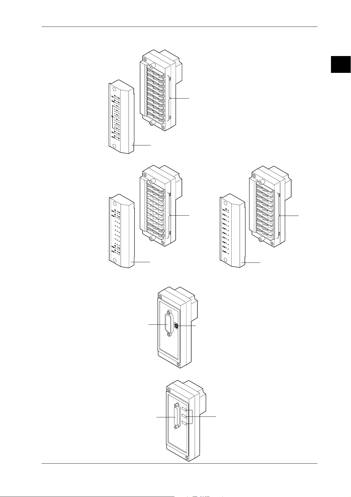
Page 23
1.3 Names of Parts
Strain input module (DU500-12/DU500-13/DU500-14)
Gauge method setup switch
Pulse input module (DU600-11)
DU500-12/DU500-13
Cover
DU500-14
NDI terminal
Clamp terminal
Screw terminal
Cover
Digital input module (DU700-11)
Cover
Screw
terminal
1-8
IM DR232-01E
Page 24
I/O Terminal Modules
1.3 Names of Parts
DI/DO module (DT100-11)
1
System Configuration
Screw terminal
Cover
Alarm module (DT200-11/DT200-21)
DT200-11
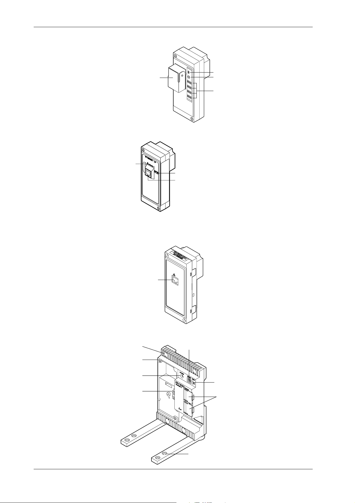
Communication Module
GP-IB module (DT300-11)
GP-IB connector
Cover
Screw
terminal
Switch to set
the address
DT200-21
Screw
terminal
Cover
IM DR232-01E
RS-232-C module (DT300-21)
RS-232-C connector
Switches to set
communication parameters
1-9
Page 25
1.3 Names of Parts
RS-422-A/RS-485 Module (DT300-31)
RS-422-A/RS-485 terminal
Ethernet module (DT300-41)
Status indicator
Switch to set mode
10BASE-T port
ON/OFF switch of built-in terminating resistor
LED
Switches to set
communication parameters
Extender Module/Extender Base
Extender Module (DV100-011)
Extension cable connector
Extender Base (DV100-012)
Inatallation
holes
Screw holes for
module installation
Power indicator
Module connector
EXTENDER
I/F
I/F
Slot number setup switch
Terminator on/off switch
Lid covering the extension
1-10
Holes for fastening the feet
IM DR232-01E
Page 26
1.4 Floppy Disk
A floppy disk drive is provided with the DR232-1 and DR242-1.
Applicable Floppy Disks
3. 5-inch floppy disks can be used for this instrument. They can also be formatted on this
instrument.
• 2HD type: 1.2 MB or 1.44 MB (MS-DOS format)
• 2DD type; 720 MB (MS-DOS format)
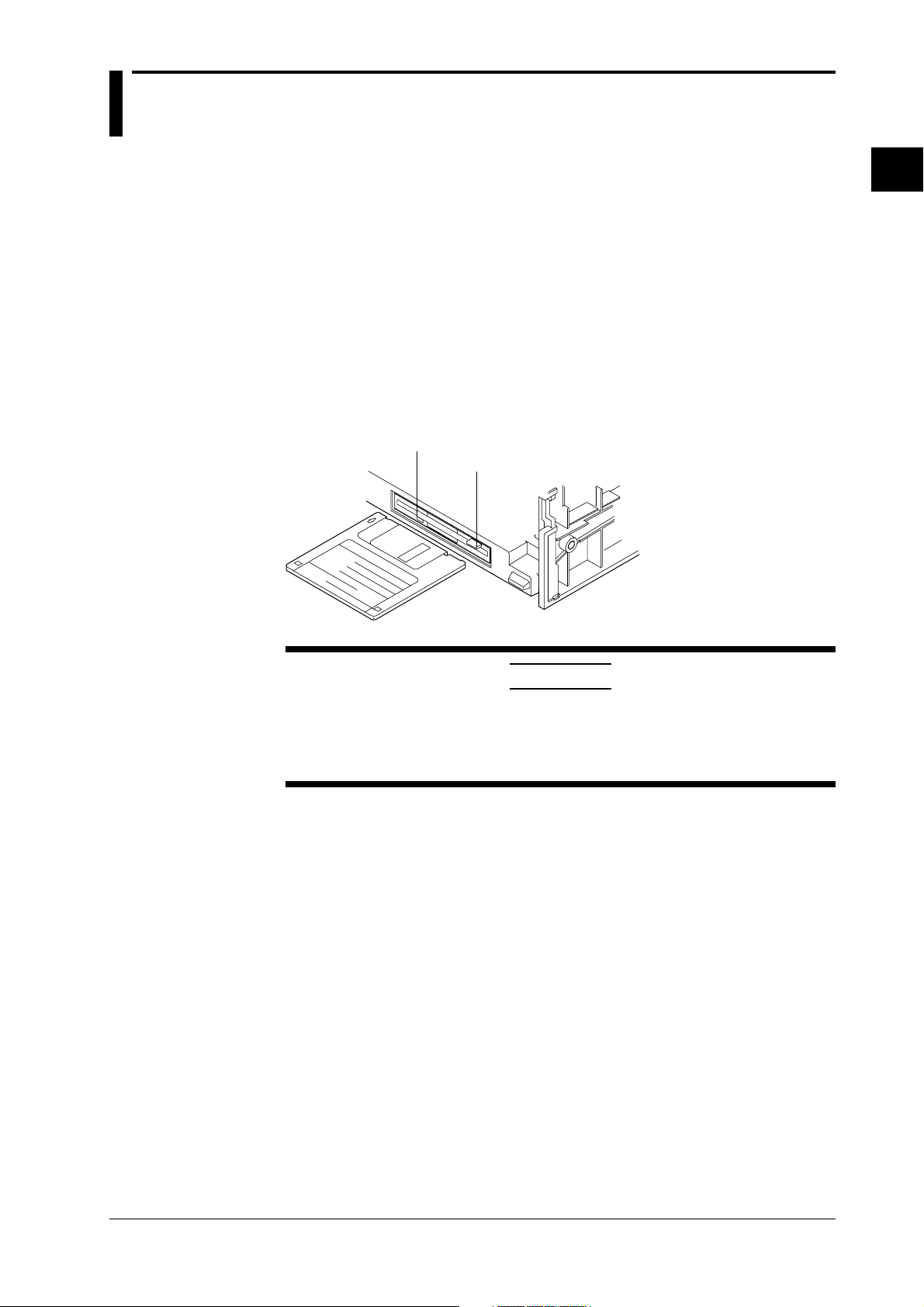
Inserting a Floppy Disk into the Drive
Insert the floppy disk into the floppy disk drive, shutter side first and with the label face up.
Make sure that the floppy disk is inserted until the eject button pops up.
Removing the Floppy Disk from the Drive
Make sure that the access indicator is not lit, then push the eject button to remove the floppy disk.
access indicator
eject button
1
System Configuration
CAUTION
If the floppy disk is removed when the access indicator is still lit, damage to
the magnetic head of the floppy disk drive or to data saved on the floppy
disk may result. Before removing the floppy disk, always make sure that
the access indicator is OFF.
General Precautions Regarding Handling of Floppy Disk
For general precautions regarding handling of floppy disks, refer to the instruction manual
provided with the disk.
IM DR232-01E
1-11
Page 27

2.1 Display Functions
The inter-active front panel display consists of three rows. The first row is the main display, and
the second and third row are sub-display 1 and 2 respectively.
Monitor Mode and Status Display
Monitor Mode
• Auto Mode
This mode can be set for the main display, sub-display 1 and sub-display 2. Measurement
values of all channels will be consecutively displayed with update interval.
• Manual Mode
This mode can be set for the main display, sub-display 1 and sub-display 2. Measurement
values of a single channel will be displayed. The display update interval is the same as the
measurement interval (refer to page 2-4).
• Manual Mode
This mode can be set for the main display. When choosing this display, the measurement values
of 5 consecutive channels will be displayed as a page using also sub-display 1 and 2. The
display update interval is the same as the measurement interval (refer to page 2-4).
• Alarm Search Mode
This mode can be set for the main display, sub-display 1 and sub-display 2. Channels at which
an alarm occurred will be searched for and their measurement values displayed. The display
update interval is 2 seconds.
• Bargraph Mode
This mode can be set for sub-display 1. Measurement values which are shown on the main
display will be shown as a bargraph. The display update interval is the same as the interval of
the main display.
• Alarm Status Mode
This mode can be set for sub-display 1 and 2. The display will show per channel whether or not
an alarm occurred (refer to page 2-13). On one display the alarm status of a maximum of 30
channels can be monitored (depending on the number of input channels). The display update
interval is 0.5 seconds.
• Relay Status Mode
This mode can be set for sub-display 1 and 2. The display will show the operating status of
internal switches/alarm output relays (refer to page 2-13). On one display a maximum of 30
relay statuses can be monitored. The display update interval is 1 second.
• Clock Mode
This mode can only be set for sub-display 2. The current date and time are shown.
• Displaying the Selected Mode
To the right of sub-display 1 the currently selected display mode is shown for a specific
display.
2
Functions
IM DR232-01E
Status Display
Indicators at the right side of the display will light up to show that recording is in progress (refer
to page 2-5), alarms are occuring (refer to page 2-13), keys are locked (refer to page 2-17) and
chart needs to be replaced (refer to page 2-18).
Remote/Local Status Display
The status of remote/local control will be show on sub-display 2. Keys cannot be operated in
remote control.
2-1
Page 28

2.1 Display Functions
Display for Setting the Type of Input, Computation and Recording Conditions
Menus for setting each of the following functions will be displayed.
• measurement input functions (refer to page 2-3)
• recording functions (refer to page 2-5)
• alarm functions (refer to page 2-13)
• calculation functions (refer to page 2-16)
• event/action function, key-lock function and external in/output function (refer to page 2-17, 18)
Display for Setting Fundamental Functions
Menus for performing fundamental settings will be displayed.
2-2
IM DR232-01E
Page 29

2.2 Measurement Input Functions
Input Type
DC Voltage
Measurements can be done after selecting the measurement range per channel. The minimum
range is 20mV, the maximum range is 50V.
Thermocouple
Measurements can be done after selecting the type of thermocouple per channel. The available
types are R, S, B, K, E, J, T, L, U, N, W and KPvsAU7FE.
Reference Junction Compensation (RJC) can be set to either use Internal RJC (INT) or External
RJC (EXT) per channel.
Burnout function can be set OFF per channel or it can be selected in which direction the trend line
will move if burnout occurs (right or left)
Resistance Temperature Detector
Measurements can be done after selecting the type of resistance temperature detector (RTD) per
channel. The available 17 types are Pt100(1mA), Pt100(2mA), JPt100(1mA), JPt100(2mA),
Pt50(2mA), Ni100(1mA)SAMA, Ni100(1mA)DIN, Ni120(1mA), J263*B, Cu10GE, Cu10L&N,
Cu10WEED, Cu10BAILEY, Pt100 (1mA) high resolution, Pt100 (2mA) high resolution, JPt100
(1mA) high resolution and JPt100 (2mA) high resolution.
Contact Input
The type of contact input can be selected from voltage level input or contact input, and recording
can be set ON or OFF per channel. In case of the voltage level input a voltage level up to 2.4V
results in recording OFF, whereas a voltage level of 2.4V or more results in recording ON.
2
Functions
DC Currents
DC currents ranging from -20 mA to 20 mA can be measured by means of the built-in 250-Ω
shunt resistors.
AC Voltages/Currents
The effective voltage, effective current, active power, reactive power, apparent power, frequency,
power factor and phase angle can be measured. The measuring range is common to all terminals.
The input terminals of the module with this input mode, unlike those of modules with other input
modes, are not consistent with a setup screen in terms of the channel number.
Strain
The module for this input mode supports the single-gauge, single-gauge three-wire (not yet
supported by the DU500-14 module), adjacent-side two-gauge, opposed-side two-gauge and fourgauge methods. If you have connected any new strain gauge or changed the measuring range, go
through initial balancing before starting measurement.
Pulses
The module for this input mode can measure the number of pulses per second on a channel basis
or detect the on/off states by means of any variations occurring in the instantaneous value every
second. Once you connect the pulse input module, you can sum up values without the need for
the computing function.
Skipping Input Channels
This function allows skipping measurement, recording and display of channels you are not using.
Measurement, recording and display will not be done for the skipped channels.
Reference Junction Compensation (RJC)
This function is to be used when measuring temperatures using thermocouples. The voltage
generated by a thermocouple depends on the temperature of the spot of measurement and the
reference junction temperature. Reference junction compensation is a function which
compensates the temperature at the side of the measurement instrument to 0 degrees C.
To compensate for the environmental temperature an internal circuit can be selected, or
compensation by a fixed compensation voltage value (external) can be set.
IM DR232-01E
2-3
Page 30

2.2 Measurement Input Functions
Scan Interval
• The duration of time (one scan) in which the measurement of all channels is carried out, is
called the scan interval.
• This interval can be set to any value from 0.5 second to 60 seconds. The shortest is 300 ch/500
ms (varies with the shortest measurement period of the input module).
A/D Integration Time
This instrument measures the input signal after putting it through an A/D converter. In order to
minimize the noise imposed on the input signal, specific integration times exist.
The integration time can be selected from 20ms (50Hz), 16.7ms (60Hz) and 100ms (10Hz).
When “AUTO” is selected, the integration time will be automatically decided according to the 50/
60Hz frequency of the power supply.
AUTO does not function if the instrument is the subunit (DS400/DS600) of the DC power supply
model (Selecting “AUTO” will set the A/D integration time to 20 ms (50 Hz)). If you are using
the instrument on a 60-Hz power supply, set the A/D integration time to 16.7 ms (60Hz).
Input Filter
A filter can be set ON/OFF to reduce normal mode noise. Effects on normal mode noise are as
follows depending on the filter being ON/OFF (theoretical values).
0dB
1Hz
Frequency
10Hz
50Hz
100Hz
300Hz
–20dB
–40dB
–60dB
Attenuation
–80dB
–100dB
Slope:–20dB/dec
Filter ON
Filter OFF
Slope:–60dB/dec
2-4
IM DR232-01E
Page 31

2.3 Recording Functions
Chart Speed
The speed at which the chart moves when performing trend recording can be selected from any
value between 1 to 1500mm/h.
Two types of chart speeds can be set. When you are not using the Event/Action function, which
will be described later on in this manual, chart speed 1 will be valid. When the Event/Action
function is being used, you can select whether chart speed 1 will change to speed 2 according to
the event status.
Recording Mode
Two types of recording modes are available; analog trend and logging mode. The default setting
is analog trend mode.
Analog Trend Mode (refer to the next page for a recording example)
Trend Recording (Dot recording)
The recording principle is that, according to measurement data and recording conditions, the
correct position on the chart will be decided and on that position the dot will be printed. Trend
recording conditions consist of the following.
• chart speed
• channels to be recorded
• recording color (refer to page 2-8)
• recording interval (refer to page 2-8)
• recording span (refer to page 2-9)
• recording zone (refer to page 2-9)
• partially expanded recording (refer to page 2-10)
• interpolation function (refer to page 2-10)
2
Functions
Digital Printout
Measurement data will be printed as numerical values. Digital printout conditions consist of the
following.
• channels to be recorded
• recording interval (refer to page 2-8)
• the number of channels to be recorded on the same line (refer to page 2-7)
Logging Mode
In this mode measurement data are only printed as numerical values. Logging recording
conditions consist of the following.
• channels to be recorded
• the recording direction (vertical or horizontal)
• recording interval (refer to page 2-8)
IM DR232-01E
2-5
Page 32

2.3 Recording Functions
Recording Example
The numbers in parentheses refer to reference pages.
Trend recording (Page 2-5)
Reference point of scale
(Page 2-7)
Scaled value
(Page 2-9)
Alarm release mark
(Page 2-12)
Alarm occurrence mark
(Page 2-12)
Right margin
Reference position of
Chart speed
(Page 2-5)
Starting time
of dot
recording
(Page 2-7)
Ending time of
previons dot
recording
(Page 2-7)
dot recording start
(Page 2-7)
Channel No. or tag of
dot recording
2-6
Manual Printout
Starting date/time
(Page 2-12)
of manual printout
Channel No. or tag
of manual printout
Digital printout
(Page 2-5)
Message
(Page 2-12)
Titlle
(Page 2-12)
Chart speed
(Page 2-5)
Starting date/time
Header
(Page 2-12)
of Digital printout
IM DR232-01E
Left margin
Page 33

Recording Format
2.3 Recording Functions
You can modify the recording format of measurement values according to your own preferences.
The following selections are available.
Items common for Analog Trend and Logging mode
Printing Channel No. or Tag
When printing measurement values, the corresponding channel number or a preset tag can be
recorded with it. This selection will also affect the display the same way. The number of
characters of a tag which will be printed out, can be selected too.
2
Items for Analog Trend Mode
Printing Starting/Stopping Time of Recording
You can select whether to print the time of starting/stopping the recording (refer to page 2-9) on
the right side of the chart. The first time recording starts after the power has been turned ON, only
the starting time will be printed. After that, the current starting time will be printed together with
the stopping time of the previous recording. To the right of the starting time a bar will be printed
as a reference point to the time of starting.
Selecting the Number of Columns for Digital Printouts
You can select how many columns (where one column equals data of one channel) will be used in
one line for printing out measurement data.
Selection of the Pitch of Channel Printouts
You can select at which distance the channel numbers (or tags) will be printed. You can also
select this printout OFF. When tags have been selected, this distance applies to the tag printout.
Selection of the Pitch of Title Printouts
You can select at which distances the title will be repeatedly printed. You can also select this
printout OFF.
Selection of the Scaled Values Printout
You can select the printing pattern for scaled values (refer to page 2-9). You can also select this
printout OFF.
Selection of the Reference Point of Scaled Values
You can select whether or not to print a reference point for the positions of the scaled values.
Items for Logging Mode
Selection of the Recording Direction (Horizontal/Vertical)
You can select whether printouts will occur in horizontal or vertical direction,
Example of a printout in horizontal direction
Functions
IM DR232-01E
Example of a printout in vertical direction
2-7
Page 34

2.3 Recording Functions
Recording Colors
Recording Interval
In the trend recording the color of the recording can be selected per channel. The colors which can
be selected are black, purple, redish purple, navy blue, red, blue, brown, green, orange and
yellowish green.
The recording color of the numerical values in the logging mode is purple only.
The time during which one scan of trend recording or numerical printout is carried out is called
the recording interval.
Recording interval for trend recording
This recording interval can be selected from AUTO or FIX.
AUTO
The recording interval is decided automatically depending on the measurement (scan) interval
and chart speed in order prevent the dots from overlapping. However, in cases where this
calculation would render the recording interval smaller than the scan interval, the recording
interval will equal the scan interval.
Recording interval = Scan interval × N
where N is an integer satisfying N
fixed.
Example: when scan interval is 2s; chart speed is 100mm/h
then N ≤ 720 / (2 × 100) = 3.6
The closest matching integer is 3.
Accordingly, the recording interval becomes 2 × 3 = 6s.
≤ 720 / (scan interval × chart speed). 720 is
FIX
Recording is carried out at an interval which is the same as the scan interval (2 to 60s)
regardless of the chart speed.
Recording interval for digital printouts
This recording interval can be selected from MULTIPLE or SINGLE
MULTIPLE
Six preset recording intervals (Timer 1 to 6) can be set and a recording interval can be selected
per channel. The timer setting can be selected from relative and absolute.
• Relative time: Time will be counted from the point of turning the power switch ON or of
resetting the timer. Each time the preset length of time is reached (and thus when time is
up), recording will start.
• Absolute time: A reference time is set, and from that time recording will start at preset time
intervals (each time when time is up).
SINGLE
The logging interval is decided automatically depending on the chart speed and the number of
columns for digital printouts.
Recording interval in logging mode
This recording interval can be selected from MULTIPLE or SINGLE
MULTIPLE
Same as for the analog trend mode
SINGLE
From the above mentioned six preset recording intervals, the interval set as Timer 1 will
become the recording interval.
Resetting the Recording Interval (Timer Reset)
This function will reset the elapsed time of the above mentioned MULTIPLE recording interval to
zero. Usually recording will start according to the recording intervals, but when you reset the
elapsed time using this function, the results are the same as for time-up.
2-8
IM DR232-01E
Page 35

Recording Span
The maximum value and the minimum value of the measurement range are decided when setting
the type of input. The difference between the minimum value and maximum value which will be
recorded within this measurement range, is called the recording span. The value on the left and
right side of the recording are called the left span and right span respectively.
Starting/Stopping Recording
Usually starting/stopping movement of the chart and trend recording is carried out by pressing the
appropriate key on the operation panel. But movement of the chart and trend recording can also
be started/stopped upon alarm occurrence or by remote control (event/action function).
Recording Method of Trend Recording
Chart movement can start by either key operation or event/action function and selected channels
will thus be recorded as trend recording.
Normal Recording
Selected channels will all be recorded regardless of the below mentioned occurrence/release of
alarms or group settings. Recording will start when the chart starts moving.
Trend Recording upon Alarm Occurrence
• Trigger Recording
All channels where an alarm occurred will be recorded. Even when the alarm is released,
recording will continue.
• Level Recording
All channels where an alarm occurred will be recorded. When the alarm is released, recording
will stop.
Group Trend Recording
Channels can be clustered in a group, and only those channels will be recorded.
2.3 Recording Functions
2
Functions
Recording Zone
Scale Values
The recording span of measurement values on the chart is called recording zone. For each channel
you can set between what locations on the chart the measurement values will be recorded.
It is possible to assign zones so that the analog trend recordings of each individual channel will
not overlap. This setting is only valid for trend recordings in the analog trend mode. The default
setting is the full recording width of 250mm.
The left and right boundary of the recording zone (left position and right position respectively)
correspond to respectively the left and right span of the recording span.
Trend of channel 1
Left position of zone 1
(=left span of ch1)
Zone 1 Zone 2 Zone 3
Right position of zone 1
(=right span of ch1)
Trend of channel 2 Trend of channel 3
Scale values are used to mark the divisions of zones and three different scale format can be
selected.
IM DR232-01E
2-9
Page 36

2.3 Recording Functions
Partially Expanded Recording
When carrying out trend recording, partially expanded recording enables you to compress a part
of the recording span in order to examine the expanded (other) part of the span in more detail. The
left boundary of the recording span being 0%, and the right boundary of the recording span being
100%, a segment of the recording span can be compressed. The following example shows a
situation where 25% of the recording span has been compressed. The points A, B, C, D, E and F
before compression correspond to the points A’, B’, C’, D’, E’ and F’ in the figure after
compression. The 25% left of the boundary shows —6 to 0V, whereas the 75% right of the
boundary shows 0 to 6V.
•Before compressing
–6 –5 –4 –3 –2 –1012345
E
Chart direction
0 50 100
0
A
D
F
(% of compression:RATE)
C
Recording
span
•After compressing 25% of recording span
12345
–6 –5 –4 –3 –2 –1
0
D’
Bounda value
A’
B’
C’
6 (V)
Measurement value
(Recording span)
B
% of full recording
span
6 (V)
Measurement value
(Recording span)
Interpolation Function
2-10
E’
Chart direction
0 25 100
F’
(% of compression:RATE)
Recording
span
% of full recording
span
When carrying out trend recording and a measurement value differs greatly from the previous
one, the track of the recording changes stepwise in the dot printing. In cases like this,
interpolation will be carried out on the horizontal line to connect the two divergent trend tracks.
When the horizontal lines of channels are to be recorded on exactly the same location, only the
recording color with the higher priority will be used.
The priority of recording colors is black > purple > redish purple > navy blue > red > blue >
brown > green > orange > yellowish green, which means that black has the highest priority. In the
figure below a recording example is given of a horizontal line in the colors black, red and
yellowish green. In the area where red and yellowish green overlap (labeled as a), only red dots
will be recorded, and in the area where black, red and yellowish green overlap (labeled as b), only
black dots will be recorded.
However, at the locations where the recordings diverge after the connecting a horizontal line, all
recording colors will be recorded.
ab
Chart direction
Red Yellowish
green
Black
IM DR232-01E
Page 37

List Printout
2.3 Recording Functions
A list printout will show the following items.
• Title (if a title has been entered)
• Date and time
• Measurement interval, recording interval, chart speed and recording mode
• Timer setting (6 Multiple and Single)
• Match time: a specific time is set and when that time is reached, a preset operation will be
carried out (refer to event/action function on page 2-17)
• Tags for each channel, input type, recording span and linear scaling values (this print can be
selected ON/OFF)
• Alarm (this print can be selected ON/OFF)
• Group setting
• For each individual channel: whether the trend mode is ON/OFF, whether interpolation is ON/
OFF, recording zone settings, partially expanded recording settings, selected Timer No.,
whether moving average is ON/OFF, alarm type and whether manual print is ON/OFF (this
print can be selected ON/OFF)
• Headers (only when input is applied)
• Contents of up to 20 messages
• Settings related to event/action function
• Selections related to this list printout
2
Functions
IM DR232-01E
2-11
Page 38

2.3 Recording Functions
Manual Printout
Header Printout
Additional Printouts
One scan of measurement values of selected channels will be recorded as digital values together
with the date and time. This printout can be executed by key operation or by event/action function
(refer to page 2-17). Refer to page 2-6 for a recording example.
A header can consist of up to 80 characters for each to up to 5 lines and recording can be executed
by key operation.
While recording analog trends it is possible to have engineering units, tags, scales, alarm, title,
messages, etc. printed along with the measurement values and the date/time.
• Engineering units; these will be printed in combination wiht the linear scaling function (refer to
page 2-16)
• Channel No. or tag; a preset tag can be printed for each channel; the selection whether to print
the channel No. or the tag (refer to page 2-7) can also be done
• Scale printout; values corresponding to the scales will be printed (refer to page 2-9)
• Alarm printout; alarm information (refer to page 2-15) will be printed upon occurrence (or
release) of an alarm. You can also set a message to appear upon occurrence of an alarm
• Title printout; A title of up to 32 characters can be printed. Furthermore, the title can be set to
be printed at regular intervals (refer to title pitch on page 2-7)
• Message printout; Recording of messages of up to 16 characters can be executed by key
operation or event/action function. Time will also be printed together with the message. Up to
20 different messages can be entered.
Set-Up List Printout
Match Time Function
Each item as described in Ch. 10 will be printed.
You can preset a time when you want recording to start/stop using the event/action function (refer
to page 2-12). When this time is reached, recording in the analog trend or logging mode will start/
stop.
2-12
IM DR232-01E
Page 39

2.4 Alarm Function
This function will show an alarm on the display or generate an alarm output signal when the
measurement conditions of a channel exceed/fall below preset values. Up to four alarms can be
set for each channel. Alarms can be set up to 4 items per channel.
Type of Alarms
Six types of alarms are available, namely high limit alarm, low limit alarm, high limit on rate-ofchange, low limit on rate-of-change, difference high limit and difference low limit.
Interval for Rate-of-Change Alarms
In case of high/low limit on rate-of-change alarms, variation is measured over a preset interval,
and if the variation exceeds a preset value, an alarm occurs. This interval can be set and applies to
all channels.
•High limit on rate-of-change
Measurement
value
T
2
T
1
Alarm Hysteresis
You can set the width between the value of alarm occurrence and its release. This setting prevents
frequent alarm occurrences/releases in an unstable environment. Hysteresis values can be set in
the 0-1% percentage range of the recording span. The hysteresis setting is used for high and low
limit alarms.
t
1
Set interval
21
t –t
Measured
variation
Set variation
T –T
21
t
Time
2
•Low limit on rate-of-change
Measur-
T
ement
value
1
T
2
t
1
Set interval
t –t
1
2
Set variation
T –T
21
Measured variation
t
Time
2
2
Functions
•High limit alarm
Alarm occurrence
1V
Measurement values
Internal Switches
Alarm Output Relays
•Low limit alarm
Measurement values
Hysteresis (Approx. 0.5%)
Alarm occurrence
Alarm release
Set alarm
value
Hysteresis
(Approx. 0.5%)
Set alarm
value
1V
Alarm release
Sixty internal switches are provided which can be operated upon alarm occurrences. These
switches are only for internal operations and are used in combination with the event/action
function (refer to page 2-17).
The alarm module or the DI/DO module includes an alarm output relay. The contact of this relay
can be output to the outside. For how to mount modules, see 3.3, “How to Connect Input/Output
Modules” (page 3-7).
IM DR232-01E
2-13
Page 40

2.4 Alarm Function
Operation Mode
Energizing/De-energizing Setting
The alarm output relays can be selected to be energized or de-energized on alarm occurrence.
Using de-energizing, the alarm output relay will be activated when the power drops in the same
way as when an alarm occurs. This setting can be done for each relay individually.
Relay contacts in case of energizing
A-contact
When power is OFF When power is on
and no alarm has
occurred
When power is on
and an alarm has
occurred
NO CNOC
When power is OFF When power is on
NO C
and no alarm has
occurred
NO CNO C
When power is on
and an alarm has
occurred
NO C
C-contact
When power is OFF When power is on
NO C NC NO C NC NO C NC
and no alarm has
occurred
When power is on
and an alarm has
occurred
Relay contacts in case of de-energizing
When power is OFF When power is on
and no alarm has
occurred
NO C NCNO C NC
When power is on
and an alarm has
occurred
NO C NC
AND/OR Setting
When a group of alarms share the same internal switch or alarm output relay, you can select how
the internal switches/alarm output relays will be operated.
AND: will be operated when all alarms are occurring;
OR: will be operated when at least one alarm is occurring.
Alarm occurrence
Alarm occurrence
Operation
Operation
Alarm status
Alarm output
relay status
Channel 1
Channel 2
AND
OR
HOLD/NON-HOLD Setting
You can select whether to hold the operating status of operated internal switches or alarm output
relays. This setting applies to both the internal switches and the alarm output relays.
2-14
Alarm status
Operation of
Internal switch/
alarm output
relay
Alarm release
Working
Alarm reset
(Refer to page 2-5)
Alarm release
Working
Reflashing Alarm Setting
When several alarms share the same alarm output relay, you can select this setting which results
in a short de-operation of the relay when a second alarm occurs.
Alarm occurrence
Alarm occurrence
Alarm occurrence
Working
Working
Approx. 200ms Approx. 200ms
Working
Working
IM DR232-01E
Alarm status
Alarm output relay
Channel 1
Channel 2
Channel 3
Reflash=ON
Reflash=OFF
Page 41

Recording Alarm Information
Analog Trend Mode
When an alarm occurs (or releases), the occurrence/release mark, message, channel No. or tag and
time of occurrence/release will be printed on the right side of the chart.
Logging Mode
• If an alarm occurs, the type of alarm will be printed together with the measured value.
• If an alarm occurs (or is canceled), the alarm occurrence/cancellation mark, channel No./TAG,
the type of alarm, time when the alarm occurs/cancels, and messages are printed after all the
measured values.
2.4 Alarm Function
2
Displaying Alarm Information
Alarm Indicator
“ALARM” Indicator
When at least one alarm occurs, the “ALARM” indicator at the right of the display will light.
Display per Channel
In sub-display 1 or 2, the alarm statuses of a maximum of 30 channels (according to the
specifications) can be displayed (refer to page 2-1). Besides, when the measurement value of a
channel where an alarm occurred is being displayed, the type of alarm will appear between the
channel number and the measurement value.
Channel No. Type of alarm Measurement value
001 H 10.000mV
Alarm Display Hold Function
This function allows the alarm display to remain even when the alarm has already been released.
This function can be selected ON or OFF and applies to all alarms. When the function is set to
ON, if an alarm occurs, the alarm display flashes.
Alarm Acknowledge Function
This function only resets the display and therefore allows you to verify the current alarm status on
the display. When the alarm display hold function is ON, selecting the ALARM ACK menu
results the alarm display changing from flashing to lit and will turn off when the alarm is released.
This setting applies to all alarms.
Alarm Reset
You can reset the internal switches and alarm output relays and the corresponding displays. The
previously mentioned alarm acknowledge function has the same function as resetting the alarm
display here. Resetting the internal switches and alarm output relays when the relay hold function
is set to ON has the following affects and depends on the alarm status.
• when alarms occur continuously, the internal switches/alarm output relays will turn to their
non-operative status for a short period but soon change into their operation status.
• when alarms are released, the internal switches/alarm output relays turn to their non-operative
status.
Functions
IM DR232-01E
2-15
Page 42

2.5 Standard Computation Functions
Standard computations such as difference between channels and linear scaling can be set with
measurement input settings. A moving average computation is also available.
Difference between Channels
This function conputes the difference between the measurement values of a selected channel
(=reference channel) and any other channel (=destination channel). This can be applied to each
channel in the same unit. The computation formula is as follows:
Result of difference between channels computation = measurement value of destination
channel — measurement values of reference channel
Linear Scaling
This function changes the left and right span of the recording span to left and right scale values
which are converted to a different physical quantity. This can be applied to each channel and a
different engineering unit can be entered for display and printouts.
Example where voltage values are cenverted into linear scaling values
Moving Average
Left span:-2V
(=left scale:-0.1A)
Right span:2V
(=Right scale:1.1A)
This function computes a moving average over a preset number of (K) measurement values. This
function is useful for displaying and recording of unsteady measurement values. The computation
formula is as follows.
D
m= (Mm-(K-1) + Mm-(K-2) + ... + Mm-2 +Mm-1 + Mm) / K
where
D
m : “m”th average value
M
m-(K-1) : the measurement value of the “K-1”th measurement before the “m”th
measurement
M
m-(K-2) : the measurement value of the “K-2”th measurement before the “m”th
measurement
..
..
M
m-2 : the measurement value of the second last measurement before the “m”th
measurement
M
m-1 : the measurement value of the last measurement before the “m”th measurement
M
m : the measurement value of the “m”th measurement
K : number of samples, and an integer ranging from 2 to 64
At the first computation, the measurement value of the first measurement will be multiplied by
the number of samples, after which the average will be taken. The measurement values of the
second and later measurements will replace these in turn, after which the average will be
calculated each time.
2-16
IM DR232-01E
Page 43

2.6 Other Functions
Event/Action Function
Following the occurrence of an event such as remote control signal (12), alarm, internal switch,
chart end signal (out-of-paper), timer, match time or key operation, any of the following actions
can occur.
• Alarm acknowledge
(refer to page 2-15)
• Alarm reset
(refer to page 2-15)
• Timer reset
(refer to page 2-8)
• Recording start/stop
According to the recording mode and recording format, recording will start/stop
• Manual printout
(refer to page 2-12)
• Digital printout
(refer to page 2-6)
• Message printout
(refer to page 2-12)
• Message display
A preset message will be displayed on the main display
• Change of chart speed/recording interval
Chart speed 1 and recording interval 1 will change to chart speed 2 and recording interval 2,
and analog trend and logging recording will be carried out. Usually recording will be carried
out using chart speed 1 (set at the menu displayed after having pressed the CHART key) and
with recording interval 1 (set at the menu displayed after having pressed the SET key at a
touch). Upon the occurrence of an event, recording will be carried out using chart speed 2 and
with recording interval 2 (set at the menu displayed after having pressed the SET key for three
seconds).
• Group trend recording
(refer to page 2-9)
• Saving and reading of measured data, computed data and set-up data
This function is available if the instrument is equipped with a floppy disk drive.
This function enables saving of data to the internal RAM disk or floppy disk and reading of
data into the instrument.
• Starting/stopping of computation, reset, clear, status clear, and group reset
This function is available if the instrument is equipped with the computation function or
equipped with a floppy disk drive.
This function enables starting and stopping of computation and resetting and clearing of
computed data.
• Flag
Valid only for models with mathematical option (/M1.)
Set the flag to 1.
2
Functions
Key-Lock Function
IM DR232-01E
This function prevents alterations by careless key operations. When the key-lock function is
activated, the indicator “KEYLOCK” at the right side of the display will be lit. All key
operations, except power ON/OFF, DISP/MODE key and the cursor, will then be disabled.
However, you can preset whether RECORD/FEED/PRINT/FUNC/M.FUNC1 and M.FUNC2
keys will remain operable even after key-lock has been set. Furthermore, when activating or
releasing the key-lock, a menu for password verification appears to prevent the key-lock to be
used by unauthorized operators.
2-17
Page 44

2.6 Other Functions
External In/Output Function (alarm module or DI/DO module is required)
Alarm Output
This output can be performed from the internal relay in the alarm module or the DI/DO module.
These relays will be operated when an alarm occurs. For details concerning their settings and their
relation with alarms, refer to page 2-14, 2-15.
Fail Output
One transfer contact in the DI/DO module is used for fail output. This relay will change to the deenergized status when a failure of the recorder occurs.
Usually In case of failure In case of power OFF
NO CNC NO CNC NO C NC
Chart End Output
One transfer contact in the DI/DO module is used for chart end output. When the chart has only
2cm or less paper, the “CHART” indicator at the right of the display will light, and recording will
stop. The relay will change to the energized status.
Usually In case of Chart end In case of power
OFF
NO C NC NO CNC NO C NC
Controlling Recording Functions by Remote Control
The recording functions can be controlled by inputting up to 12 contact signals to the DI/DO
module. You can choose one of the following operations for each of the 12 signals. The remote
control function can be one of the events of the event/action function described on the previous
page.
• Alarm acknowledge
• Alarm reset
• Timer reset
• Recording start/stop
• Manual printout
• Digital printout
• Message printout
• Message display
• Change of chart speed/recording interval
• Group trend recording
2-18
IM DR232-01E
Page 45

Communication Interface (Communication module required)
Either GP-IB interface module, the RS-232-C interface module or RS-422-A/RS-485 interface
module can be connected. For details regarding operation and commands, refer to IMDR231-11E.
Internal Illumination (Option)
Clear internal illumination for easy distinction of traces is available as an option. Internal
illumination will be provided when the power is turned ON.
FDD (DR232-1, DR242-1)
This function enables saving/reading of measured data, computed data and set-up data for SET
mode to/from the internal RAM disk, and saving/reading of set-up data for SET and SETUP
modes to/from a floppy disk.
This also allows you to use events provided by the event/action function as a trigger to save/
retrieve measured/computed data to/from the internal RAM or retrieve set-up data when an event
takes place.
Computation Function (Option)
This function is available if the instrument is equipped with the computation function (/M1
model).
This function executes the following computations, and displays and records the results.
Four arithmetical operations (addition, subtraction, multiplication, division), square root, absolute
values, common logarithm, natural logarithm, power, logical product, logical sum, exclusive OR,
logical negation, statistical operation, relational operation
Up to 60 channels can be used for computation. It is also possible to use the event/action function
to start/stop computation or clear data for computation channels. Furthermore, up to 4 levels of
alarm (upper-limit alarm, lower-limit alarm) can be set for computation channels.
2.6 Other Functions
2
Functions
RRJC (Remote RJC, available if the instrument is equipped with the optional MATH
function)
In cases where the object is located in distance for temperature measurement using
thermocouples, the temperature of the object can be measured without using a number of
expensive thermocouples if a junction terminal is installed near the object. This method requires
the object to be connected to the terminal via a thermocouple, and the terminal to this instrument
via copper lead wires. Furthermore, the junction terminal needs to be connected to an input
terminal of this instrument via a thermocouple. The temperature of the junction terminal is then
measured to carry out compensation for the reference contact point used for measurement of
temperature of the object, then finally temperature of the object is measured.
This instrument
Thermocoupler*
Copper lead wire
Input
terminals
Copper lead wire
* Thermocouplers of the same type must be used
Junction terminal
(to be provided by the customer)
Reference channel
Thermocoupler*
Thermocoupler*
Computing & Report Function (Option)
This function can print the results of a statistical calculation of data on a specified channel
(measurement or computation channel), in a format predetermined for a preset time, date or
month, or send out the results to a communication line. The types of computations are averaging
(mean value, maximum and minimum), instantaneous value calculation and summation (sum,
cumulative sum).
IM DR232-01E
2-19
Page 46

3.1 General Precautions for Installation
Safety Precautions
Read the safety precautions
Make sure to read the safety precautions described on page 6 before using the instrument for the
first time.
Do not remove any covers from the instrument
For internal inspection or adjustment, contact your nearesst sales representative. Addresses may
be found on the back cover of this manual.
In case of malfunctioning
Never continue to use the instrument if there are any symptoms of malfunctioning such as unusual
sounds, smell or smoke coming from the instrument. Immediately turn OFF the power and unplug
the power cord. When using an adapter for direct wiring to the power supply, immediately turn
OFF the power supply. Also disconnect the power to the equipment under measurement. Contact
your sales representative or nearest service center. Addresses may be found on the back cover of
this manual.
Power Cord
Nothing should be placed on the power cord ; it should also be kept away from any heat sources.
When unplugging the power cord from the outlet, never pull the cord itself. Always hold the plug
and pull it. If the power cord is damaged, contact your dealer for replacement. Refer to page 2 for
the part number when placing an order.
3
Installation and Wiring
General Handling Precautions
Never place anything on top of the instrument
Never place another instrument or any objects containing water on top of the instrument.
Otherwise a failure may occur.
When moving the instrument
First turn off the power of the equipment being measured and disconnect the measurement
leadwires and the communication cable. Then turn the power switch of this instrument OFF and
unplug the power cord from the outlet. When carrying the instrument, securely hold the
instrument with both arms and take care not to drop it.
Ventilation openings
Do not block the ventilation openings in order not to raise the internal temperature.
Electrically charged objects
Don’t bring electrically charged objects near the input terminals. The internal circuitry might be
damaged.
Chemicals
Do not pour volatile agents on the case nor leave the case in contact with rubber or PVC products
for a long period. The case is made of a thermoplastic resin, so take care not to let anything hot
such as a soldering iron touch the case.
Cleaning
When cleaning the case or any other part of the instrument, first remove the power cord from the
receptacle (and in case of direct connection, disconnect the power lines). Do not use volatile
chemicals since this might result in dis-coloring etc. Always use a dry, soft cloth for cleaning.
IM DR232-01E
When not using the instrument for a long time
When the instrument is not being used for an extensive period of time, unplug the power cord
from the outlet (when using an adapter for direct wiring to the power supply, disconnect the
power cord from the outlet).
3-1
Page 47

3.2 How to Install
Installation Conditions
The instrument must be installed in a location where the following conditions are met.
Ambient temperature and humidity
• Ambient temperature: 0 to 50°C
However, in case you mount the AC power supply model subunits DS400/DS600 directly to a
panel, or if you apply the DIN rail, or mount them in a rack, it is possible to use them in a range
of –10 to 60°C.
• Ambient humidity: 20 to 80%RH for –10 to 40°C, 10 to 50%RH for 40 to 50°C, 5 to 30%RH
for 50 to 60°C (However, no condensation should be present.)
• Installation location: Room
• Installation height: Altitude up to 2,000 m
Note
Internal condensation may occur if the instrument is moved to another place where both the ambient
temperature and humidity are higher, or if the temperature changes rapidly. In case of thermocouple input,
this might result in erroneous measurements. In those cases, allow the instrument to achieve eqailibrium
with to its new environment for at least one hour before starting operation.
WARNING
• When the environmental temperature is 50°C or more, the temperature
of the rear panel may rise to more than 70°C. Thus, touching the rear
panel under these circumstances has the danger of sustaining burns.
• To prevent a fire, always use the instrument in a vertical position, and
do not block the upper side of the modules (a space of at least 3cm is
necessary).
Installation Method
Never install the instrument in any of the following locations:
• in direct sunlight or near heat sources
• where an excessive amount of soot, steam, dust or corrosive gases are present
• near strong magnetic field sources
• near high voltage equipment or power lines
• where the level of mechanical vibrations is high
• in an unstable place
DR232
Can be used on a desk-top, installed on the floor, or rack-mounted. Always install the instrument
vertically.
• saDesk-top or floor installation
Install the instrument vertically on a horizontal flat floor as shown below.
3-2
IM DR232-01E
Page 48

3.2 How to Install
• Rack mounting
The following fittings can be supplied for rack mounting.
Name Model Description
Rack mount fitting DV400-013 Conforming to ANSI/EIA
• External dimensions and rack mounting dimensions for the DR232 are shown below.
• To install the rack mount fitting on the instrument, remove the screws at the right and left
forward of the instrument and use the mounting screws attached to the rack mount fitting.
Be careful that right and left screws have different lengths. The screw at the right when
facing the front of the instrument is M4 of 20 mm long and the left screw is M4 of 16 mm
long. Appropriate tightening torque is 1.4 to 1.5 N·m (14 to 15 kgf·cm).
• If another instrument is to be mounted under this instrument in an ANSI/EIA rack, remove
the prong or brackets designated with 2 and 3 in the figure below because they may interfere
with both instruments.
3
Installation and Wiring
266
25
438
30
207
63.6
Rack Mounting Dementions
11.3
6.8
265.9±1
190.5±0.5
482.6±1
11.3
6.8
190.5±0.537.7
30
265.9±1
Panel face
IM DR232-01E
37.7
112
1&2 : Removed
3-3
Page 49

3.2 How to Install
DR242
• Panel mounting
Use steel plates 3 mm thick or more for panel mounting.
The external and panel cutting dimensions for the DR242 are shown below. The panel cutting
dimensions include the cutting interval for multiple mounting on the same panel.
The DR242 weighs about 12 kg, so a shelf should be provided to support the DR242 behind the
panel.
Insert the instrument from the front face of the panel.
Insert the blocks of the mounting brackets as accessories into the rectangular holes (after
removing seals) on right and left sides of the instrument, push the brackets toward the rear, and
engage the blocks with rectangular holes.
When a screw attached on each bracket is turned clockwise, the entire brackets are pushed
against the panel rear. Tighten the screws to securely fix the instrument to the panel. Proper
screw-tightening torque is 0.8 to 1.2 N·m (8 to 12 kgf·cm).
The brackets can be used for panels of 3 to 26 mm thick.
288
444
At least 80 mm
40
Panel cutting dimensions
At least 520 mm
203 64.8
280
3-4
425
281
+2
0
IM DR232-01E
Page 50

Legs
M4 screws
3.2 How to Install
DS400/DS600
The subunit DS400/DS600 can be used on a desk-top, installed on the floor, directly panelmounted, mounted on DIN rails, or rack-mounted. Always mount the instrument vertically. If
the power terminals of the unit are screw terminals, directly mount the unit on the panel to
prevent electric shock.
• Desk-top use or installed on the floor
Extend the legs on the bottom of the unit forward as shown below and place the unit vertically.
If the unit could fall when wired, use the through-holes of the legs to fix the legs with the
attached four 4-mm screws.
3
Installation and Wiring
• Direct panel mounting
Following the figure below, fix the unit at six places using the attached screws (length: 16 mm).
M4 screws
• Mounting on DIN rails
For the mounting procedure, see the instruction manual for “DIN rail mounting fitting.”
IM DR232-01E
3-5
Page 51

3.2 How to Install
• Rack mounting
The following fittings are supplied for rack mounting. For details of the mounting procedure,
see the instruction manual for “rack mounting fitting.”
Name Model Description
Rack mounting fitting DV400-011 For DS400/DS600 conforming to ANSI/EIA
3-6
IM DR232-01E
Page 52

3.3 How to Connect the Input/Output Modules
WARNING
When connecting the Input/Output modules, make sure to turn OFF the
power to the DR232/DR242/DS400/DS600 to prevent an electric shock
or damage to the instrument.
Setting the Unit Number of each Subunit
When connecting subunits to the DR232/DR242, it is necessary to assign a distinctive unitnumber to each subunit. This number can be selected from 0 to 5 (the setting 6 and up will not be
recognized) and is set, as shown in the figure below, by a setting switch (rotary dipswitch).
Note
When you connect an input module at the location of the setting switch, the switch can not be operated
anymore. Therefore, make sure you set the switch before connecting any input module there.
It is convenient for confirming unit numbers to write each unit number setting on the gray concave surface
at the top of DS600 subunit (or on the left side of DS400 subunit).
Connecting Method
1. Verify that the power to the DR232/DR242/DS400/DS600 has been turned OFF.
2. Remove the cover of the location where the module will be connected. Do not remove any
cover of locations where no module will be connected.
3. Hold the input unit so that the male part of the connector at the back side of the input unit
matches the female part of the receiving connector. Then connect the unit.
4. Fasten the input unit by fastening the two accessory M3 screws.
Cover
Input
module
Screws to fasten the module
Switch for setting
the unit number
Module connector
• Switch for setting the
unit number
(settable from 0 to 5)
3
Installation and Wiring
0
1
9
2
8
3
7
4
6
5
Modules Which Can be Used
Not more than one DI/DO module can be connected to all units.
• Main unit DR232/DR242
Alarm module, DI/DO module, and communication interface module.
(Note: The input module cannot be connected.)
Number of modules that can be connected: 1
• Subunit DS400/DS600
Input module, alarm module, and DI/DO module.
Number of modules that Dqn be connected: 4 for DS400, 6 for DS600 (up to 300)
DS400: Input module + alarm module + DI/DO module: max. four
DS600: Input module + alarm module + DI/DO module: max. six
Note
• No alarm module or DI/DO module can be connected to the right side of an input module, since the rise
in temperature would hinder the measurement accuracy. Verify the type of module by the seal on the top
side.
• Do not connect the universal input module and the power monitor module in slots next to eachother.
Keep them at least 1 slot apart. If you mount the power module immediately beside the universal
module, the measuring accuracy of the universal module may fall out of its guaranteed range because of
the heat radiating from the power module.
IM DR232-01E
3-7
Page 53

3.3 How to Connect the Input/Output Modules
Location and Location Number (Channel Number, Alarm Output Relay Number, DI/DO
Number)
The location numbers correspond to channel numbers for locations where the input module is
connected, to alarm output numbers for locations where the alarm module is connected, and to DI/
DO numbers for locations where the DI/DO module is connected.
Modules are mounted on a unit in slots. The number of each module is the same as that of the
slot.
As shown below, input/output location numbers are assigned related to the unit number (see the
previous page; the main unit number is fixed at I) and module location.
Module 0 (Location numbers:101 to I10)
Main unit DR232/DR242
Input modules cannot be
connected.
Unit No.:I
Module 5 (Location numbers:051 to 060)
Module 4 (Location numbers:041 to 050)
Module 3 (Location numbers:031 to 040)
Module 2 (Location numbers:021 to 030)
Module 1 (Location numbers:011 to 020)
Module 0 (Location numbers:001 to 010)
Subunit DS600
Unit No.:0
Module 3 (Location numbers:131 to 140)
Module 2 (Location numbers:121 to 130)
Module 1 (Location numbers:111 to 120)
Module 0 (Location numbers:101 to 110)
Subunit DS400
Unit No.:1
Note
When the following handling is done, it is necessary to carry out “system construction” to operate the
instrument correctly. After executing system construction, confirm the module information. For details,
see page 9-16.
· Connection (including addition or replacement)/removal of subunits, or unit number setting (see page 3-
7)
· Mounting (including addition or replacement)/removal of modules
3-8
IM DR232-01E
Page 54

3.4 Installing the Chart and Ribbon Cassette
Install the chart.
Preparing the Chart
1. To prevent double feed of the folded chart, sufficiently ruffle and fan the chart on both folded
side ends.
Note
• Use chart papers specified by Yokogawa (part number: B9627RY or B9627AY). Using chart papers
other than those specified may cause problems such as large recording errors or the paper getting caught
under the sprocket.
Preparing the Chart Cassette
2. Open the front door and draw out the chart cassette from inside of the main unit by pulling
forward the chart cassette pressers while simultaneously pushing them (both right and left
pressers) toward the center.
3
Installation and Wiring
Chart cassette
Chart cassette presser
3. Open the chart pressure plate 1 by pulling the right and left lever of the chart pressure
plate 1.
Lever of chart
pressure plate 1
Chart cassette
Chart pressure plate 1
4. Open upward the chart pressure plate 2 by simultaneously pushing the right and left latch
release buttons of the chart pressure plate 2.
Sprocket
Platen
IM DR232-01E
Chart pressure plate 2
Latch release button of
chart pressure plate 2
3-9
Page 55

3.4 Installing the Chart and Ribbon Cassette
Loading the Chart Paper
5. Place the chart paper in the chart storage housing, and move the paper to the left. Position the
chart so that its round perforations are on the left and the recording surface faces upward when
the chart paper is wound around the platen.
Chart paper
Platen
6. Pass the chart paper through the gap between the chart pressure plate 1 and the platen.
Chart paper
Chart pressure plate 2
Chart storage housing
Fold line of chart paper
Sprocket
Right and left
position mark
Chart rest cover
Chart pressure plate 1
Guide pin
7. Align the right and left chart paper perforations. Set the chart paper so that the right and left
marks of the sprockets and the fold line are aligned.
8. Close the chart pressure plate 1 until it latches. Confirm that the horizontal lines of the chart
paper are parallel with the horizontal line of the chart pressure plate 1. If they are not parallel,
open the chart pressure plate 1 and align the right and left perforations again.
9. Close the chart pressure plate 2 until it latches.
10.Fitting the guide pin of the chart cassette in the main unit guide groove, place the chart cassette
on the bottom of the main unit and slide the cassette deep inside the main unit until the latch
engages.
11.Turn on the power of the main unit and feed the chart paper by pressing the FEED key on the
operation panel. Feed the chart paper by three folds or more to the chart paper rest and check
that the paper is fed properly. Check this in the same way when the chart paper is fed manually
without recording. If the chart paper is not fed properly, repeat the procedure from step 2. For
details of turning the power on, see page 3-33.
12.When the chart paper approaches the end, the words “RENEW CHART” in an scarlet strip on
the paper appear. Prepare a new set of chart paper.
13.When the letters “CHART” in the status indicator in the display light, it indicates that the
paper has run out. Replace the chart with a new one according to the above procedure.
*To remove the chart paper from the chart rest, open the chart rest cover and take out the paper.
3-10
IM DR232-01E
Page 56

Loading the Ribbon Cassette
Preliminary Preparation
• If the carriage to which the ribbon cassette is to be mounted is located near the right end, turn
off the power and bring the carriage to a location near the left end by turning the screw shaft,
then load the ribbon cassette.
• Set the RECORD key on the operation panel to OFF and set all the recording actions for the
event/action functions (see page 9-1) to OFF so that recording does not start while loading the
ribbon cassette. If applicable, turn off the power.
Note
Do not perform recording without the ribbon cassette loaded, otherwise the platen may be scratched or the
chart paper may break.
3.4 Installing the Chart and Ribbon Cassette
3
Load the Ribbon Cassette in the DR232.
1. Open the front door and remove the chart cassette cassette from the main unit.
2. Press the red lever at the bottom of the carriage. The ribbon cassette holder moves to the right.
Ribbon cassette holder
Screw shaft
Red lever
3. Touch the ribbon cassette holder with a finger and tilt the housing downward.
4. Turn the ribbon cassette rotating knob in the direction of the arrow (counterclockwise) to take
up the ribbon slack.
Installation and Wiring
IM DR232-01E
5. Fit the projection of the housing into the slot of the ribbon cassette and insert the cassette fully
into the holder.
6. Bring up the front part of the cassette until it latches and make sure it is horizontal.
3-11
Page 57

3.4 Installing the Chart and Ribbon Cassette
7. Push the ribbon cassette to the left until the latch engages. Check that the three white lines of
the printer head are not visible when viewed from the front. If the white lines can be seen, the
ribbon cassette is not properly loaded. Push the cassette to the left again.
8. Turn the ribbon cassette rotating knob once more in the direction of the arrow
(counterclockwise) to take up the ribbon slack.
9. Return the chart cassette to the main unit.
10.Feed the chart paper by pressing the FEED key on the operation panel to prevent a delay in
starting the chart paper feed.
Note
• Check that the ribbon cassette is properly loaded in the carriage.
• If a ribbon cassette is used for a long time, the ribbon may become wavy and move out of the dot printing
range of the printer head. If this happens, replace the ribbon with a new one.
Load the Ribbon Cassette into the DR242.
1. Open the front door and open the display door. The ribbon cassette can be loaded without
removing the chart cassette from the main unit.
2. When the chart cassette is removed, press the red lever 1 at the bottom of the carriage. When
the chart cassette is not removed, pull forward the red lever 2, then the ribbon cassette holder
moves to the right.
Red lever 2
Red lever 1
Ribbon cassette holder
3. Turn the ribbon cassette rotating knob in the direction of the arrow (counterclockwise) to take
up the ribbon slack.
4. Fit the projection of the holder into the slot of the ribbon cassette and insert the cassette fully
into the holder.
3-12
IM DR232-01E
Page 58

3.4 Installing the Chart and Ribbon Cassette
5. Push the ribbon cassette to the left until the latch engages. Check that the three white lines of
the printer head are not visible when viewed from the front. If the white lines can be seen, the
ribbon cassette is not properly loaded. Push the cassette to the left again.
6. Turn the ribbon cassette rotating knob once more in the direction of the arrow
(counterclockwise) to take up the ribbon slack.
7. Feed the chart paper by pressing the FEED key on the operation panel to prevent a delay in
starting the chart paper feed.
Note
• Check that the ribbon cassette is properly loaded in the carriage.
• If a ribbon cassette is used for a long time, the ribbon may become wavy and move out of the dot printing
range of the printer head. If this happens, replace the ribbon with a new one.
3
Installation and Wiring
IM DR232-01E
3-13
Page 59

3.5 Connecting the Interface Cables
When connecting a personal computer to the instrument via a communication interface, observe
the following:
GP-IB
The GP-IB connector of the GP-IB communication module is a 24-pin connector of IEEE St’d
488-1978. Only use cables that conform to IEEE St’d 488-1978 as a communication cable.
Connection Procedure
Connect the cable as shown in the figure below.
GP-IB module
Personal
computer
Ferrite core
•When connecting the cable, take note of the following.
• To reduce noise, use two ferrite cores (e.g., ZCAT 3035-1330 from TDK) at both ends of the
interface cable as shown above.
• Securely tighten the screws which fasten the GP-IB cable connector.
• If more than one equipment is connected, the same addresses cannot be assigned to different
equipment.
• Use only cables of 2 m or less to interconnect each equipment.
Ferrite core
Function
grounding
terminal
How to Assign an Address
The address can be assigned easily by turning the rotary dipswitch as shown in the figure below.
Any address can be set from “0” to “15”; the characters “A” to “F” on the dipswitch correspond to
the address “10” to “15” respectively.
0
1
2
F
3
0
1
2
F
3
E
4
D
5
C
6
B
7
A
8
9
E
4
D
5
C
6
B
7
A
8
9
3-14
IM DR232-01E
Page 60

RS-232-C
3.5 Connecting the Interface Cables
Communication Settings
Communication parameters are set using the three switches located on the RS-232-C modules.
Switch 1
Switch 2
Switch 3
1234
1234
1234
ON
OFF
Data length
Baud rate
ON
OFF
Not used
Stop bit
Parity
ON
OFF
Not used
Handshake format
Switch 1 and No.4 of switch 2
Baudrate dipswitch No.1 No.2 No.3 No.4 (Switch 2)
150 OFF OFF OFF OFF
300 OFF OFF ON OFF
600 OFF ON OFF OFF
1200 OFF ON ON OFF
2400 ON OFF OFF OFF
4800 ON OFF ON OFF
9600 ON ON OFF OFF ←initial value
19200 ON ON ON OFF
38400 OFF OFF OFF ON
Data length dipswitch No.4
7 OFF
8ON←initial value
3
Installation and Wiring
Switch 2
Parity dipswitch No.1 No.2
NONE OFF OFF
ODD OFF ON
EVEN ON OFF ←initial value
Stop bit dipswitch No.3
1 OFF ←initial value
2ON
Switch 3
Handshake format dipswitch No.1 No.2 No.3
no handshake OFF OFF OFF ←initial value
XON-DTR* OFF OFF ON
XON-RTS* OFF ON OFF
CTS-DTR OFF ON ON
CTS-RTS ON OFF OFF
* When the baud rate is set to 38400, there is no handshake.
Note
When you are using the accessory standard software, the settings should be as follows: baud rate 2400 to
19200bps, data length: 8 bit, parity: ODD, stop bit: 1.
IM DR232-01E
3-15
Page 61

3.5 Connecting the Interface Cables
Connecting the RS-232-C cable
For details on connecting the RS-232-C connector of the RS-232-C communication interface
module to a personal computer, see IM DR231-11E, “DR231/DR232/DR241/DR242
Communication Interface User’s Manual.”
When (dis)connecting the RS-232-C cable, turn OFF the power of both
the personal computer and the instrument. If the power is not turned
OFF, malfunctions may occur and the internal circuitry may be
damaged.
Note
To reduce noise, use ferrite cores (e.g., ZCAT 3035-1330 from TDK) for the interface cable as shown
below. Two ferrite cores should be installed near both ends of the interface cable. If the noise is
particularly bad, use several ferrite cores in series. Use a shielded cable for the interface cable and make a
one-point grounding at the ground terminal of this instrument together with the functional-ground terminal
of the personal computer.
Personal
computer
CAUTION
Ferrite core
Function
grounding
terminal
RS-422-A/RS-485
SW1
SW2
SW3
SW4
1234
1234
1234
1234
ON
OFF
Data length
Baud rate
ON
OFF
four-wire/two-wire
Stop bit
Parity
ON
OFF
Address (upper)
Minimum response time
ON
OFF
Address (lower)
Baud rate (No.1 to 3 of SW1)
Baud rate No.1 No.2 No.3
300 OFF OFF ON
600 OFF ON OFF
1200 OFF ON ON
2400 ON OFF OFF
4800 ON OFF ON
9600 ON ON OFF ←Default Setting
19200 ON ON ON
38400 OFF OFF OFF
3-16
Data length (No.4 of SW1)
Data length No.4
7 OFF
8ON←Default Setting
IM DR232-01E
Page 62

3.5 Connecting the Interface Cables
Parity (No.1 to 2 of SW2)
Parity No.1 No.2
None OFF OFF
ODD OFF ON
EVEN ON OFF ←Default Setting
Stop bit (No.3 of SW2)
Stop bit No.3
1 OFF ←Default Setting
2ON
Switch between four-wire/two-wire systems (No.4 of SW2)
four-wire/two-wire No.4
four-wire OFF ←Default Setting
two-wire ON
Minimum response time (No.1 to 3 of SW3)
Minimum response time No.1 No.2 No.3
0ms OFF OFF OFF ←Default Setting
10ms OFF OFF ON
20ms OFF ON OFF
50ms OFF ON ON
100ms ON OFF OFF
Address (No.4 of SW3 and No.1 to 4 of SW4)
Address No.4(SW3) No.1(SW4) No.2(SW4) No.3(SW4) No.4(SW4)
1 OFF OFF OFF OFF ON ←Default Setting
2 OFF OFF OFF ON OFF
3 OFF OFF OFF ON ON
4 OFF OFF ON OFF OFF
5 OFF OFF ON OFF ON
6 OFF OFF ON ON OFF
7 OFF OFF ON ON ON
8 OFF ON OFF OFF OFF
9 OFF ON OFF OFF ON
10 OFF ON OFF ON OFF
11 OFF ON OFF ON ON
12 OFF ON ON OFF OFF
13 OFF ON ON OFF ON
14 OFF ON ON ON OFF
15 OFF ON ON ON ON
16 ON OFF OFF OFF OFF
17 ON OFF OFF OFF ON
18 ON OFF OFF ON OFF
19 ON OFF OFF ON ON
20 ON OFF ON OFF OFF
21 ON OFF ON OFF ON
22 ON OFF ON ON OFF
23 ON OFF ON ON ON
24 ON ON OFF OFF OFF
25 ON ON OFF OFF ON
26 ON ON OFF ON OFF
27 ON ON OFF ON ON
28 ON ON ON OFF OFF
29 ON ON ON OFF ON
30 ON ON ON ON OFF
31 ON ON ON ON ON
3
Installation and Wiring
IM DR232-01E
3-17
Page 63

3.5 Connecting the Interface Cables
For details on connectin the RS-422-A/RS-485 connector of the RS-422-A/RS-485
communication interface module to a personal computer, see IM DR231-11E, “DR231/DR232/
DR241/DR242 Communication Interface User’s Manual.”
When (dis) connecting the RS-422-A/RS-485 cable, turn OFF the power
of both the personal computer and the instrument. If the power is not
turned OFF, malfunctions may occur and the internal circuitry may be
damaged.
Ethernet
CAUTION
Dip Switch
ON
OFF
1234
10BASE-T Port
Connect the RJ-45 modular jack
of the twist pair cable connected
to the 10BASE-T network.
Status
Indicator LED
Tx (yellow)
LINK (yellow)
STS1 (green)
STS2 (green)
)
You can select the following three modes by setting the dip switch.
Configuration mode: A mode in which the IP address, subnet mask, and default gateway are set
for the DR.
Test mode: A mode in which the condition of the physical connection is tested.
Communication mode: A mode in which the DR is connected to the network to carry out
communication. Use this mode to read in the DR measurement data with
the PC.
In addition, you can turn ON/OFF the Keepalive function.
Mode Setting
Mode Switch 1 Switch 2
Configuration mode ON OFF
Test mode OFF ON
Communication mode OFF OFF ←Default Setting
Do not set both dip switches, 1 and 2, to ON.
3-18
Keepalive Setting
Keepalive Switch 3
Enable ON
Disable OFF ←Default Setting
Keepalive is a function supported by TCP. It sends packets at constant time intervals and
automatically disconnects when there is no corresponding response. This instrument sends
packets at 30-second time intervals. If a response is not received, it sends 4 more packets at onesecond intervals. If a response is still not received, the connection is dropped.
Have dip switch 4 turned OFF.
IM DR232-01E
Page 64

3.6 Connecting the Extension Cables-
Extension Cables
Any of the following extension cables can be used for connections between the DA100 main unit
and subunits or for connections between subunits.
Name Model Description
Extension cable DV200-000 Length: 0.5m
Extension cable DV200-001 Length: 1m
Extension cable DV200-002 Length: 2m
Extension cable DV200-005 Length: 5m
Extension cable DV200-010 Length: 10m
Extension cable DV200-020 Length: 20m
Extension cable DV200-050 Length: 50m
Extension cable DV200-100 Length: 100m
Extension cable DV200-200 Length: 200m
Extension cable DV200-300 Length: 300m
Extension cable DV200-400 Length: 400m
Extension cable DV200-500 Length: 500m
Connecting Procedure
Insert the plug of the extension cable in the connector until you hear a click. Since both
connectors are identical, it makes no difference which connector you use. Furthermore, since both
plugs of the cable are identical, you may use either end.
When pulling the plug from the connector, gently press the peg of the plug and pull it forward.
3
Installation and Wiring
Extension cable
Note
When the following handling is done, it is necessary to carry out “system construction” to operate the
instrument correctly. After executing system construction, confirm the module information. For details,
see page 9-16.
• Connection (including addition or replacement)/removal of subunits, or unit number setting (see page 3-
7)
• Mounting (including addition or replacement)/removal of modules
Points to Note when Using the Extension Cables
• The maximum rated temperature is 60°C;
• Never disconnect the extension cable from the connector by pulling the cable, since this might
damage the signal cable. Always hold the plug.
• When wiring the extension cable through a cable duct, or metal pipe or such, protect the peg on
top of the plug by covering it with tape.
• For extension cables of longer than 50 m connect the plug with copper foil directed towards the
main unit DA100. Applying it in reverse direction might increase noise.
• Fasten the cabels in such a way that no force is applied to the connector or the plug.
• To prevent the wire from snapping, etc. do no apply a tensile force of more than 70N.
Furthermore, do not bend the cable in a radius of 3 centimeters or less.
• For the environmental conditions for wiring, refer to Section 3.11, “Countering Noise” (page 3-
35).
Note
When several sub-units are connected, and the power is turned off of one of them, the other connected subunits which are further away from the main unit will not be recognized anymore.
Lid
Plug
IM DR232-01E
3-19
Page 65

3.7 Connecting the Signal Lines
W WARNING
• To prevent electric shock, always make sure that the power supply is
turned OFF before connecting.
• When 30 VAC or 60 VDC and more is applied to the output terminal of
the alarm module or the output terminal of the DI/DO module, use
double-insulated wires(withstand voltage performance: more than 2300
VAC) for those wires which apply 30 VAC or 60 VDC and more. All
other wires can be basic-insulated(withstand voltage performance: more
than 1350 VAC). Furthermore, use “crimp-on” lugs (for 4 mm screws)
with insulation sleeves for connecting to the screw terminal. Make sure
that the crimp-on tool must be one specified by the crimp-on lugs
manufacture, and that the crimp-on lugs and tool must be matched to
the wire size. To prevent electric shock, do not touch the terminal after
wiring and make sure to re-apply the cover.
CAUTION
• Do not apply an input voltage exceeding the following levels to each
terminal of each module. Otherwise, the internal circuits may be
damaged.
Allowable input voltage
Universal or DCV/TC/DI input module
2 VDC range or less, RTD, TC and DI(CONT) : ±10 VDC
6 to 20 VDC range, DI(LEVEL) : ±60 VDC
Digital Input module
CONT(Voltage-free contact input) : ±10 VDC
LEVEL(Voltage input) : ±60 VDC
mA-input module : ±5 VDC
Strain input module : Don’t input voltage to the terminal.
Pulse input module : 5 VDC
DI/DO module : –2 to 7 VDC
Max. common mode noise voltage
Universal, DCV/TC/DI input, digital Input, mA-input modules : 250
VACrms (50/60 Hz)
• Output contact rating for DI/DO or Alarm input modules is 250 VDC/0.1
A (resistive load), 250 VAC/2 A (resistive load), 30 VDC/2 A (resistive
load).
• The overvoltage category of each input module is CAT ll (IEC 1010-1).
• When connecting to a clamp terminal, use a signal conductor with the
following cross-sectional width:
Solid conductor 0.14 to 2.5 mm
Stranded conductor 0.14 to 1.5 mm
AWG 26 to 14
2
2
3-20
IM DR232-01E
Page 66

Connecting Procedure
g
3.7 Connecting the Signal Lines
1 Check that the power switch of this instrument is turned off.
2 Remove the terminal cover. (the figure below shows DU100-11.)
Terminal cover
Screws for fastenin
the cover
3 Fasten the signal wires to the terminals as shown in the figure on the next page.
4 Re-apply the terminal cover and fasten the screws.
3
Installation and Wiring
Note
Make sure that the equipment connected to the signal in-/output conforms IEC (CSA) 950 or IEC (CSA)
1010. Also, make sure to use cables that conform to IEC (CSA) standards.
In case you are using an internal RJC in case of thermocouple input, the following considerations are
necessary to stabilize the temperature at the terminals. Always make sure to re-apply the terminal cover;
The thermal capacity of the wiring should be small (cross sectional area of less than 0.5mm2); Minimize
outside temperature fluctuations as much as possible.
To prevent noise, make sure to ground each unit at the grounding function terminal (below the power
switch) together at one point.
Refrain from wiring the input signals parallel. However, if you do, then the following considerations are
necessary. Ground all equipment at the same point; Do not turn the power of other equipment ON/OFF
during operation; Do not use the burnout function.
IM DR232-01E
3-21
Page 67

3.7 Connecting the Signal Lines
Wiring Input Signal Lines (Universal, DCV/TC/DI, and Digital input modules)
Terminals
Screw type terminal
+
-
Bb
A
DC voltage • TC •
contact
1
RTD*
CH1
CH2
CH2
CH4
Clamp type terminal*
2
*1 There are no RTD
input terminals on
the DCV/TC/DI and
Digital input module.
*2 There is no clamp
type terminal for
Digital input module.
+
A
CH1
-
B
b
CH3
CH10
Wiring Diagram
DC voltage input/DI input (contact)
DC voltage input
+-
Compensation lead
CH9CH10
DC input
+-+-
+
-
Shunt resistor
Note:For 4 to 20mA input, shunt
resistance value should
RTD inputTC input
bAB
be 250Ω ±0.1%
10Ω* max./leadwire
Three wire resistances
should be approx. equal.
*10Ω max. for Pt100Ω and
Pt50Ω, 1Ω max. for Cu10Ω.
DC current input
+
-
b
A
B
Wiring DC-current Input Signal Lines (mA-input Module)
Diagrams of Terminal Block and Wiring
Model with Clamp Terminals
CH2
CH4
CH10
+
–
3-22
Model with Screw Terminals
–
+
CH1
CH2
CH10
CH1
CH3
CH9
–
+
+
DC-current input
–
IM DR232-01E
Page 68

Wiring Strain Input Signal Lines (Strain Input Module)
CH2
CH3
CH5
CH7
CH9
CH1
CH4
CH6
CH8
CH10
Jumper setup switches
CH1
CH3
CH5
CH7
CH9
CH2
CH4
CH6
CH8
CH10
NDI terminal
Please apply the optional DV450-001 strain conversion cable when using a bridge box or strain
gage without sensor line.
Wiring Diagrams
Model with Built-in Bridge Model with External Bridge Resistors
Wiring Diagrams
• Single-gauge method
3.7 Connecting the Signal Lines
3
Installation and Wiring
Rg
R
R
Rg
E
DU500-12/DU500-13
Jumper setup switch
No.1
No.2
No.3
No.4
No.5
OFF
No.1ONNo.2ONNo.3ONNo.4
R
r
r
R
R
ON
e
Rg
OFF
A(+)
B(L)
C(-V)
D(H)
No.5
OFF
Rg
• Single-gauge three-wire method
R
e
DU500-14
R = fixed resistor
r = resistance of leadwire
Rg = resistance of strain gauge
e = output voltage developed across bridge
E = voltage imposed across bridge
12 3 4
56
R = fixed resistor
r = resistance of leadwire
Rg = resistance of strain gauge
e = output voltage developed across bridge
E = voltage imposed across bridge
78
IM DR232-01E
r
E
3-23
Page 69

3.7 Connecting the Signal Lines
DU500-12/DU500-13 DU500-14
Jumper setup switch
No.1
No.2
No.3
No.4
No.5
OFF
No.1ONNo.2ONNo.3
• Adjacent-side two-gauge method
ON
OFF
A(+)
Rg
C(-V)
D(H)
No.4ONNo.5
OFF
B(L)
12 3 4
56
78
R
Rg1
DU500-12/DU500-13 DU500-14
Jumper setup switch
No.1
No.2
No.3
No.4
No.5
No.1ONNo.2ONNo.3
E
OFF
R
Rg2
ON
OFF
e
Rg1
Rg2
No.4
OFF
A(+)
C(-V)
D(H)
No.5
ON
Rg2
Rg1
B(L)
• Opposed-side two-gauge method
R
Rg1
Rg2
e
R
E
Rg1
Rg2
R = fixed resistor
r = resistance of leadwire
Rg = resistance of strain gauge
e = output voltage developed across bridge
E = voltage imposed across bridge
12 3 4
56
R = fixed resistor
r = resistance of leadwire
Rg = resistance of strain gauge
e = output voltage developed across bridge
E = voltage imposed across bridge
78
Rg1
Rg2
3-24
DU500-12/DU500-13 DU500-14
Jumper setup switch
A(+)
Rg1
No.1
No.2
No.3
No.4
No.5
OFF
No.1ONNo.2
OFF
ON
No.3
ON
No.4
OFF
Rg2
No.5
ON
B(L)
C(-V)
D(H)
Rg2
1234
78
6
5
Rg1
IM DR232-01E
Page 70

• Four-gauge method
3.7 Connecting the Signal Lines
Rg4
Rg1
Rg3
Rg2
R = fixed resistor
e
r = resistance of leadwire
Rg = resistance of strain gauge
e = output voltage developed across bridge
E = voltage imposed across bridge
E
Rg1, Rg3
Rg2, Rg4
Rg1
Rg2
Rg1
Rg3
Rg3
Rg4
Rg1, Rg2
DU500-12/DU500-13 DU500-14
Jumper setup switch
A(+)
No.1
No.2
No.3
No.4
No.5
Rg4
Rg1
B(L)
Rg2
C(-V)
Rg3
D(H)
No.2
OFF
ON
No.3
OFF
No.4
OFF
No.5
ON
OFF
No.1
OFF
Rg3 Rg4
Rg3Rg4
12 3 4
56
Rg1
78
Rg2
3
Installation and Wiring
Wiring Pulse Input Signal Lines (Pulse Input Module)
Open collector
TTL open collector
-+
CH1
CH2
CH3
CH4
Contact
-+
CH1
CH2
CH3
CH4
Wiring Output Signal and Remote Control Signal Lines (DI/DO and Alarm modules)
Terminals
NC
C
NO
Failure output (transfer-contact)
Chart end output (transfer-contact)
Remote control signal input
(12 contact terminals)
1
ALM output
(transfer-contact)
2
Terminal arrangement
NC
C
NO
FAIL
NC
C
NO
CHART
2
C
1
4
C
3
6
C
5
REM
8
C
7
10
C
9
12
C
11
NC
C
NO
ALM
1
NC
C
NO
ALM
2
NO C
NC
DT200-11DT100-11
Alarm output
1
2
(transfer contact)
Alarm output
3
(transfer contact)
4
NO C
DT200-21
1
2
10
Alarm
output
(make
contact)
IM DR232-01E
3-25
Page 71

3.7 Connecting the Signal Lines
Wiring AC Input Signal Lines (Power Monitor Module)
WARNING
• For hazard prevention, ALWAYS provide protective grounding before
connecting measuring leadwires.
• When connecting any object being measured, ALWAYS turn off the
power to the object. It is extremely dangerous to connect or disconnect
interconnecting leadwires with the power to the object left on.
• Exercise utmost care to avoid connecting any current-mode circuit to a
voltage-input terminal or any voltage-mode circuit to a current-input
terminal. Wrong connection may result in damage to the circuit or
equipment being measured or the DR232 or DR242 recorder itself, as
well as bodily injury.
• Fuses are not built into voltage- and current-input terminals. ALWAYS
install a fuse on the interconnecting leadwire. Use a fuse that will not
permit the voltage or current being measured to exceed the maximum
ratings of an AC input module.
The maximum voltage and current that can continuously be imposed on
an AC input module are as follows:
Voltage: 250 Vrms; current: 5 Arms
• To avoid electrical shock, ALWAYS attach the terminal cover in place
after the completion of wiring to the terminals so that the terminals
cannot be accidentally touched.
CAUTION
• In wiring, use double-insulated leadwires that have sufficient
withstanding-voltage and current-carrying-capacity margins against the
voltage and current being measured and meet the ratings at which they
are used.
• ALWAYS clamp measuring leadwires with the wire clips to prevent the
wires from being disconnected from their terminals. As the measuring
leadwires, use wires 0.2 to 2.5 mm2 (AWG14 to 25) thick so they can
be fastened securely with the wire clips.
• The power monitor module is a product belonging to Installation (Overvoltage) Category CAT II.
Diagram of Terminal Block
Three-phase Model
V1
I1
V2
I2
V3
I3
Wire clip
Single-phase Model
Wire clip
V1
I1
3-26
9mm
• Strip 9 mm of insulation off the leadwire.
• ALWAYS clamp the leadwire with the wire
clip.
• The recommended torque for fastening the
wire clip screw is 0.4 to 0.5 N•m.
Wire clip
IM DR232-01E
Page 72

Wiring Diagrams
• Single-phase Two-wire Configuration
±
A
SOURCE
A
V
V
±
LOAD
SOURCE
FUSE
3.7 Connecting the Signal Lines
LOAD
FUSE
V1
A1
SOURCE
• Single-phase Three-wire Configuration (power monitor modules for three-phase
use only)
A
SOURCE
±
1
A
V
1
V
N
±
±
3
V
LOAD
SOURCE
N
FUSE
FUSE FUSE
FUSE
V1
V
3
A
±
A
A1
• Three-phase Three-wire Configuration (dual-current/dual-voltage measurement;
power monitor modules for three-phase use only)
±
A
1
A
R
V
1
V
ST
±
LOAD
±
V
3
3
A
A
V
±
R
S
T
FUSE
SOURCE
FUSE FUSE
FUSE
V1
A1
LOAD
V3
A3
• Three-phase Three-wire Configuration (triple-current/triple-voltage
measurement; power monitor modules for three-phase use only)
LOAD
V3
A3
3
Installation and Wiring
SOURCE
IM DR232-01E
SOURCE
±
A
1
A
R
V
ST
±
2
A
A
3
A
A
V
1
V
2
V
±
±
V
3
LOAD
±
V
±
SOURCE
R
S
T
FUSE
FUSE FUSE
FUSE
V1
A1
FUSE
FUSE
V2
A2
LOAD
V3
A3
• Three-phase Four-wire Configuration (power monitor modules for three-phase
use only)
±
A
1
A
R
N
ST
A
V
1
V
±
±
V
3
V
A
3
A
±
±
V
2
V
2
A
±
LOAD
SOURCE
R
S
T
N
LOAD
FUSEFUSEFUSE
V1
A1
FUSEFUSEFUSE
V2
A2
V3
A3
3-27
Page 73

3.8 Connecting an Extension Module to Extension Bases
Using an extension module and extension bases, you can install input modules at a location
distant from the sub-unit(s). The module and bases are powered from the sub-unit and, therefore,
can be located even in a place where there is no power source nearby.
Installing an Extension Base
WARNING
• For fire prevention, use extension bases in an upright position.
Do not cover up the extension base's module (allow a clearance of at
least 3 cm around the module).
Ambient Temperature and Humidity
Use an extension base under the following environmental conditions:
• Ambient temperature: –10˚ to 60˚C
• Ambient humidity: 20 to 80% RH at -10˚ to 40˚C
10 to 50% RH at 40˚ to 50˚C
5 to 30% RH at 50˚ to 60˚C
Use the extension base in a condensation-free condition.
Note
Condensation may occur if you move the extension base from an area of low humidity to an area of high
humidity or if any drastic temperature variation takes place. In addition, a measurement error will result if
the DR recorder is in the thermocouple input mode. In that case, allow at least one hour for the extension
base to adjust to the ambient atmosphere before using it.
Do not install the extension base where:
• it is exposed to direct sunlight or there is a heat source nearby;
• soot, steam, dust and/or corrosive gas is relatively abundant;
• there is a strong electromagnetic source nearby;
• there is high-voltage equipment or a power line nearby;
• it is exposed to severe and/or frequent mechanical vibration; or
• it is not positioned stably.
Desk-top or Floor Installation
Attach the two supplied shoe plates onto the extension base with two screws (4-mm screws 16
mm long, supplied as standard accessories), as shown in the figure on the left below. Then, place
the extension base in an upright position. If the base is liable to fall on its side after wiring, fix
the shoe plates with the four supplied screws (4-mm screws 12 mm long) using the through-holes
(for 4-mm screws) of the shoe plates.
Direct Mounting on Panel
According to the figure on the right below, fix the extension base onto a panel by fastening the
four corners with the supplied screws (4-mm screws 12 mm long).
3-28
IM DR232-01E
Page 74

3.8 Connecting an Extension Module to Extension Bases
Connecting Extension Bases to an Extension Module
Verify that the power of the DR/DS400/DS600 has been turned off before connecting the
extension module/extention base.
Mount the extension module onto the sub-unit. The module cannot be mounted to the DR
recorder itself. Wire the extension module to the extension base with an extension cable. You
can wire a maximum of three extension bases to one extension module at the same time. It is not
possible, however, to wire extension bases in such a manner that the total sum of modules already
mounted on the sub-unit and the extension bases being wired exceeds the maximum number of
modules (four for the DS400 sub-unit and six for the DS600 sub-unit) allowed for mounting on
the sub-unit.
Either a 10-channel universal input module (DU100-11 or DU100-12) or a 10-channel DCV/TC/
DI module (DU200-11 or DU200-12) can be mounted onto each extension base.
Extension module (DV100-011)
3
Extension
cable
b -/B +/A
CH
1
CH
2
CH
3
CH
4
CH
5
CH
6
CH
7
CH
8
CH
9
CH
10
EXTENDER
POWER
I/F
I/F
ADDRESS TERMN
2
1
0
9
I/F
3
7
8
b -/B +/A
CH
1
CH
2
CH
3
CH
4
CH
5
CH
6
CH
7
CH
8
CH
9
CH
10
4
ON
5
6
OFF
b -/B +/A
CH
1
CH
2
CH
3
CH
4
CH
5
CH
6
CH
7
CH
8
CH
9
CH
10
b -/B +/A
CH
1
CH
2
CH
3
CH
4
CH
5
CH
6
CH
7
CH
8
CH
9
CH
10
Extension cable
ADDRESS TERMN
POWER
3
2
4
1
5
0
6
9
7
b -/B +/A
CH
1
CH
2
CH
3
CH
4
CH
5
CH
6
CH
7
CH
8
CH
9
CH
10
8
I/F
b -/B +/A
CH
1
CH
2
CH
3
CH
4
CH
5
CH
6
CH
7
CH
8
CH
9
CH
10
STATUS
SUB UNIT
100-240V 50/60Hz 70VA MAX
POWER
Sub-unit (DS400/600)
Slot number setup switch
Select an unused slot number.
ON
Terminator on/off switch
OFF
Set this switch to ON for the last extension
base in the connection.
Either a 10-channel universal input module
(DU100-11 or DU100-12) or a 10-channel
DCV/TC/DI module (DU200-11 or DU200-12)
Extension base (DV100-012)
Wiring Distance
The last extension base in the connection can be located at a maximum distance of 30 m from the
sub-unit.
Installation and Wiring
IM DR232-01E
Setting of Terminator On/Off Switch
Set the terminator on/off switch of an extension base to ON for the base that is the last in the
connection. Set these switches of all other extension modules to OFF.
Setting of Slot Numbers
Select an unused slot number for each extension base. This can include, however, a slot number
for an extension module. The following figure shows how the numbers you set correspond to the
positions of slots and relate to channel numbers.
3
2
4
1
5
0
6
9
7
8
Setpoint 6
X51-X60
3
2
4
1
5
0
6
9
7
8
Setpoint 5
X41-X50
3
2
4
1
5
0
6
9
7
8
Setpoint 4
X31-X40
3
2
4
1
5
0
6
9
7
8
Setpoint 3
X21-X30
3
2
4
1
5
0
6
9
7
8
Setpoint 2
X11-X20
2
1
0
9
Setpoint 1
X01-X10
Setpoints of slot number
3
4
5
setup switch on an
6
7
8
extension base
Channel numbers, where
X is the unit number
3-29
Page 75

3.9 Connecting the Power Cord and Turning the Power ON/OFF
When Using the Accessory Power Cord
DR232/DS400/DS600 (when using the accessory power cord)
Follow the warnings below to avoid electric shock or damaging the instrument.
WARNING
• Connect the power cord only after confirming that the voltage of the
power supply matches the rated electric power voltage for this
instrument.
• Connect the power cord after checking that the power switch of this
instrument is turned off.
• To prevent electric shock or fire, always use the power cord supplied by
Yokogawa.
• Always use protective grounding to prevent electric shock. Connect the
power cord of the instrument to a three-pole power outlet which has a
protective ground terminal.
Do not use the function grounding (
connecting part as the protective ground terminal.
• Never use an extension cord that does not have protective grounding,
otherwise the protection feature will be negated.
• An AC outlet (auxiliary for the DS400/DS600) should be used to supply
power to the DS400/DS600 using a power cable(DV400-051)
separately available. Do not use this AC outlet to supply power to the
other equipments nor use other cables for the power connection.
Otherwise, the current flowing through the AC outlet will exceed the
permissible current, thereby resulting in the fuse blowing, overheating
or burning may occur.
marked terminal) under the power
Connecting Procedure
1. Check that the power switch is turned off.
2. Connect the plug of the accessory power cord to the power connector.
3. Plug the other end of the power cord into a power outlet that satisfies the following conditions:
For DS400/DS600 in order to cut down on unnecessary radio interference, attach a clamp filter
(accessory) near the power cord plug as shown below. Make a loop with the power cord and
clamp it in the clamp filter.
Rated supply voltage : 100 to 240 V AC (free power supply),operating voltage: 90 to 250 V AC
Rated supply voltage frequency : 50/60 Hz
Power consumption : DR232 ... About 130 VA max.
DS400 ... About 55 VA max.
DS600 ... About 70 VA max.
Use a three-pole power outlet provided with a protective ground terminal.
• DR232 • DS400/DS600
Power connector
AC outlet(Auxiliary
for DS400/DS600)
Power switch
Power cord
Status
indicator
Power connector
3-30
IM DR232-01E
Page 76

3.9 Connecting the Power Cord and Turning the Power ON/OFF
When Using an Adapter for Direct Wiring to the Power Supply
DR242/DS400/DS600 (when connecting wires to screw terminals)
This applies only to products with power inlet W suffix code.
Follow the warnings below to avoid electric shock or damaging the instrument.
WARNING
• Connect the power wires after checking that the power supply is turned
off to prevent electric shock.
• To prevent fire, use 600 V PVC insulated wire (AWG18) for both power
and ground wiring (cross section of 0.83 mm
corrosion finish, insulation thickness more than 0.8 mm, insulation
resistance more than 50 MΩ/km at 20°C, approved EN60 320
(VDE0625)), or equivalent cables.
• Units equiped with screw type terminals should only be used in panel
installations.
• Before turning on the power, always ground the protective ground
terminal. Do not use the function grounding terminal (
terminal) under the power connecting part as the protective grounding
terminal.
• For AC power and ground wiring, use “crimp on” lugs (for 4mm screws)
with insulation sleeves. Make sure that the crimp-on tool must be one
specified by the crimp-on lugs manufacture, and that the crimp-on lugs
and tool must be matched to the wire size.
• To prevent electric shock, do not touch the terminals after wiring.
• An AC outlet (auxiliary for the DS400/DS600) should be used to supply
power to the DS400/DS600 using a power cable(DV400-051)
separately available. Do not use this AC outlet to supply power to the
other equipments nor use other cables for the power connection.
Otherwise, the current flowing through the AC outlet will exceed the
permissible current, thereby resulting in the fuse blowing, overheating
or burning may occur.
• Make sure to apply a power switch in the power supply cord with the
following characteristics:
• rated power current > 3 A
• rated rush current > 90 A
2
or thicker, anti-galvanic
marked
3
Installation and Wiring
IM DR232-01E
Connecting procedure (DR242)
1. Check that the power switch is turned off.
2. Remove the cover protecting the power terminals.
3. Connect the power supply wires and the protecting ground wire to the power terminals.
4. Replace the cover.
Connecting procedure (DS400/DS600)
1. Check that the power switch is turned off.
2. Remove the cover protecting the power terminals.
3. Connect the power supply wires and the protecting ground wire to the power terminals.
4. Replace the cover.
In order to cut down on unnecessary radio interference, attach a clamp filter (accessory) near
the power cord plug. Make a loop with the power cord and clamp it in the clamp filter.
Rated supply voltage : 100 to 240 V AC (free power supply),operating voltage: 90 to 250 V AC
Rated supply voltage frequency : 50/60 Hz
Power consumption : DR242 ... About 130 VA max.
DS400 ... See previous page.
DS600 ... See previous page.
• DR242 • DS400/DS600
AC outlet(Auxiliary
for DS400/DS600)
N
L
Power supply wires
Power terminals
Protective ground wire
N
L
Power supply wires
Power terminals
Protective ground wire
3-31
Page 77

3.9 Connecting the Power Cord and Turning the Power ON/OFF
DS400/DS600(when using DC power supply connecter)
This applies only to products with power supply 2 suffix code.
Follow the warnings below to avoid electric shock or damaging the instrument.
WARNING
• Connect the power wires after checking that the power supply is turned
off to prevent electric shock.
• To prevent fire, use wires with cross sectional area of 0.3mm
or more.
CAUTION
• If you connect the + and - terminals in reverse on the DS400/DS600,
the internal fuse will be blown (You cannot replace the fuse by yourself.
The instrument needs servicing in this case). If there is a possibility of
reversing the polarity, insert a fuse (rating shown below) in the wiring.
This will lower the chances of blowing the internal fuse.
Fuse : 250 V/T2.5 A to T4A (time lag), 20 mm glass tube fuse,
2
I
t = 12.5 to 32
(Recommended: A1350EF (250 V/T2.5 A, I
FST0034.3121))
2
(22AWG)
2
t=12.5: SCHURTER:
Connecting procedure
1.Check thst the power switch is turned off.
2.Connect the accessory DC power terminal connector (part No. A1105JC) to the power wire and
the DS400/DS600. Use a power wire with a cross sectional area of 0.3 mm
2
(22AWG) or
more.
Soldering
21
- (0 V DC)
+ (10 to 32 V DC)
DS400/DS600
Rated supply voltage:12 to 28 V DC
Operating supply voltage:10 to 32 V DC
Power consumption:About 25 VA max.
• DS400/DS600: DC power supply model
DC power terminal
connector
3-32
DC power
terminal
IM DR232-01E
Page 78

3.9 Connecting the Power Cord and Turning the Power ON/OFF
DS400/DS600(when using optional AC adapter)
This applies only to products with power supply 2 suffix code.
Follow the warnings below to avoid electric shock or damaging the instrument.
WARNING
• Connect the power wires after checking that the power supply is turned
off to prevent electric shock.
• To prevent electric shock or fire, always use the power cable supplied
by YOKOGAWA.
• Before connecting the power cord, check that the voltage on the supply
side matches with the voltage rating of this recorder.
• When not using the instrument for a long time, unplug the power cord of
the AC adapter.
• Only use the AC adapter from YOKOGAWA (Model No.: DV500-00x).
• Do not put objects on top of the AC adapter or the power cord. Also, do
not let heat generating objects come in contact with them.
• When unplugging the power cord, do not pull on the power cord.
Always hold the plug. If the power cord becomes damaged, contact
your nearest representative listed on the back cover of this manual.
3
Installation and Wiring
Connecting Procedure
1. Check that the power switch is turned OFF.
2. Connect the AC adapter to the AC adapter jack on DS400/DS600.
3. Connect the power cord plug that came with the AC adapter to the power supply connector of
the AC adapter.
4. Connect the plug on the other end of the power cord to a power outlet meeting the following
specifications.
The power outlet should be a three-pole type with a protective grounding terminal.
Rated power supply voltage: 100 to 240 VAC
Permissible supply voltage range: 90 to 250 VAC
Rated supply voltage frequency: 50/60 Hz
Maximum power consumption: 90 VA
AC adapter rated output voltage: 12 VDC
AC adapter maximum rated output current: 2.6 A
• DS400/DS600: DC power supply model
DC power terminal
connector
Power connector
for AC power supply
AC adapter
Power cord for
AC power supply
IM DR232-01E
Functional grounding
When using the AC adapter, noise may be reduced if the functional ground is connected to the
earth GND. Use the functional ground terminal as necessary.
3-33
Page 79

3.9 Connecting the Power Cord and Turning the Power ON/OFF
Switching the Power ON/OFF
DR232/DR242
The power switch is a push-button; the power is turned on when pressed once and turned off
when pressed again.
Power switch
Note
• Before turning the power on, check that each unit is properly mounted and the power cord is correctly
connected.
• If nothing appears on the display when the power switch is turned on, turn off the power and check the
following:
• Is the power cord properly connected?
• Is the supply voltage within the range noted on the previous page?
• Is the power fuse blown (see page 13-2)
If the problem still cannot be fixed, there may be an equipment problem; please contact your nearest
sales representative. Addresses may be found on the back cover of the manual.
• The device takes about 30 minutes to warm up.
• The service life of the lithium battery used to save the settings is about 10 years at an ambient
temperature of 23°C. If the settings cannot be held because the lithium battery has run down, please
contact your nearest sales representative. Addresses may be found on the back cover of the manual.
DS400/DS600
When the “
” side of the power switch is pressed, the power is turned on and when the “O” side
of the switch is pressed, the power is turned off. When the power is turned on, the status indicator
(see the figure on page 3-30) lights.
Note
• Before turning the power on, check that each unit is properly mounted and the power cord is correctly
connected.
• If the status indicator does not go on when the power switch is turned on, turn off the power and check
the following:
• Is the power cord properly connected?
• Is the supply voltage within the range noted on the previous page?
If the problem still cannot be fixed, there may be an equipment problem; please contact Yokogawa
Engineering Service Corporation (contact details on rear cover) for repair.
• If the status lamp flashes, it means that there is an internal error. Turn off the power switch and check the
same items as for the DR242. If the problem still cannot be fixed, there may be an equipment problem;
please contact your nearest sales representative. Addresses may be found on the back cover of the
manual.
• If the power of a subunit is turned on and off with multiple subunits connected, subunits connected
subsequently to the end from the subunit whose power is turned off will not be recognized temporarily.
• The device takes about 30 minutes to warm up.
3-34
IM DR232-01E
Page 80

3.10 Setting the Date and Time
RECORD
ALARM
CHART
KEYLOCK
SET=CLOCK
>Select Setting Parameter
CHART CLOCK
Main menu
SET=
CLOCK
D I S P M O D E
E S C
P R I N TF U N C
I N S D E L
R A N G E A L A R M
S E TC H A R T E N T E R
R E C O R D
F E E D
M. F U N C 1
M. F U N C 2
• Press the CHART key to display the CHART menu.
• Set and select
using .
• To escape while using a single menu, press the MODE(ESC) key. The menu returns to the first
menu to which the single menu belongs. Note that newly selected or set items will be
canceled.
• When the device displays that setting is completed, the newly set or selected details are fixed.
Lower menu
96/01/01 03:36:23
>Set Date & Time YY/MM/DD HH:MM:SS
*** SET OK***
ENTERENTER
ESC
Setting the Date and Time
Set them in the order of year/month/day, hour:minutes:seconds.
• Year: Specify the lower two digits of the year. Example: 1996 → 96, 2000 → 00
• Month, day: Use two digits for each.
• Hour: 00 to 23
Press the ENTER key at the set time to make it effective.
3
Installation and Wiring
Note
The date and time settings are backed up by the lithium battery in the main unit.
IM DR232-01E
3-35
Page 81

3.11 Countering Noise
Types and Features of Noise Sources
Commercial Power Supply
It is necessary to consider both 50 and 60Hz as noise components. It is important to note that a
power supply line in which a thyristor or inverter is incorporated functions not only as an “energy
surplus line”, but also as a “supply surplus line”.
Thyristor (SCR)
A thyristor is used to control power through ON/OFF modulation of commercial power by
controlling the phase angle.
50Hz
or
60Hz
Voltage
noise
*Load
Thyristor
Unit
*heaters, etc.
phase angle
Thyristor waveform
Current
When the thyristor turns ON or OFF, a pulse noise is superimposed on commercial power supply,
and its pulse width is approximately 1µs. Accordingly, thyristor noise can be defined as follows.
· thyristor noise = commercial power supply + pulse noise
Inverter
Commercial power supply is converted to direct current by a rectifier (sometimes the thyristor is
used as the rectifier to stabilize direct current) and then modulated by a switching transistor and
finally converted into alternating current at the desired frequency (from tens to hundreds of Hz) to
drive a motor, for example. If the load to be driven is a fluorescent lamp, the frequency is tens of
kHz. Accordingly, inverter noise can be defined as follows.
Inverter noise = commercial power supply + pulse noise (high density) + variable low frequency
noise
Since the density of pulse noise is high compared to that of a thyristor and in addition, there is
variable frequency noise, it is difficult to consider a countermeasure for inverter noise.
Commercial
power supply
Rectifier output DC output Inverter output
3-36
Commercial
power supply
Rectifier DC filter Inverter Motor
Principle of inverter
IM DR232-01E
Page 82

Voltage
waveform
Current
waveform
3.11 Countering Noise
3
Installation and Wiring
Voltage/current waveforms of an inverter
Propagation of Noise
Relay
A relay is frequently used to amplify alarm and temperature controller outputs. However, since a
counter-electromotive force (counter e.m.f.) is produced by coil inductance when the relay is
turned off and the e.m.f. becomes noise, care must be taken. Due to chattering at the relay contact,
tens to hundreds of kHz noise occurs mainly in bursts. Thus, the noise energy often becomes high.
Transceiver
In large-scale plants, transceivers are often used for communications between the field and the
control room. Although W/G of the Japanese Electric Measuring Instruments Manufacturers
Association recommends to use transceivers covering a wave band of 27MHz, smaller-sized
transceivers for the 140 or 470MHz wave band are often used.
Noise Simulator
To test the immunity to pulse noise (mainly thyristor noise), a noise simulator is often used. A test
noise of approximately 1kV for 0.8µs is used synchronously with the power supply frequency.
Since data acquisition equipment is often used for measurements of equipment subjected to the
pulse noise test, the influence of noise must be considered.
• Noise is propagated in the following three ways.
Conduction: noise is conducted through a power line, input wiring, etc.
Electrostatic induction: noise leaks through capacitances between wires and instruments.
Electromagnetic induction: a loop in the input line, etc. induces an AC voltage by detecting the
AC magnetic field.
In real applications, the above three propagation paths are not independent of each other. Their
combination propagates noise to the equipment and causes problems.
IM DR232-01E
• Examples of noise propagated through each of these paths are given below.
Conduction: inverter noise, relay noise, thyristor noise, and noise caused by
surface temperature measurement of a power transistor, etc.
Electrostatic induction: commercial power supply noise such as the hum of audio
equipment, relay noise, etc.
Electromagnetic induction: magnetic leakage flux from a power transformer or motor, magnetic
field from a high-frequency induction furnace, the rotating magnetic
field of a power generator (Cu10Ω), etc.
The figure on the next page shows the propagation paths using practical examples.
3-37
Page 83

3.11 Countering Noise
Example of a high-frequency
induction furnace
Inverter power supply
(20 to 3500kW)
Power
supply
(0.2k to 10kHz)
Electro magnetic induction noise
Electrostatic induction noise
Room
temperature
* Due to electromagnetic induction, current i flows
through the conductor, creating joule heat which
heats the furnace.
J=i2r
Furnace
C
Φ
r
i
Temperature
inside
furnace
Hot-line conduction
noise
Electro magnetic
induction noise
Electrostatic
induction noise
Line noise
Basics of Anti-Noise Measures (part 1)
Common Mode Noise and Normal Mode Noise
Signal source
resistances Normal mode noise
Signal
voltage E
Z
3
Common mode noise
Common Mode Noise (ECM)
Noise generated between the signal source and the ground of a measuring instrument. Since it is
applied to both the H and L input terminals in phase with one another, it is also called in-phase
voltage.
The instrument
Power
supply
R1
R2
E
CM
Inputs
Signal component
E
O
Output
+
E
ONM
Normal mode noise
component
1
Floating amp
Circuit
common
i1
Case
H
E
NM
L
Z2Z
i2
3-38
Normal Mode Noise (E
NM
)
This is an unfavorable noise that is superimposed on a signal voltage. Since it is a voltage
between the H and L terminals, it is also called the line voltage, or since it is a voltage in series
with the signal voltage, it is sometimes called the series mode voltage.
IM DR232-01E
Page 84
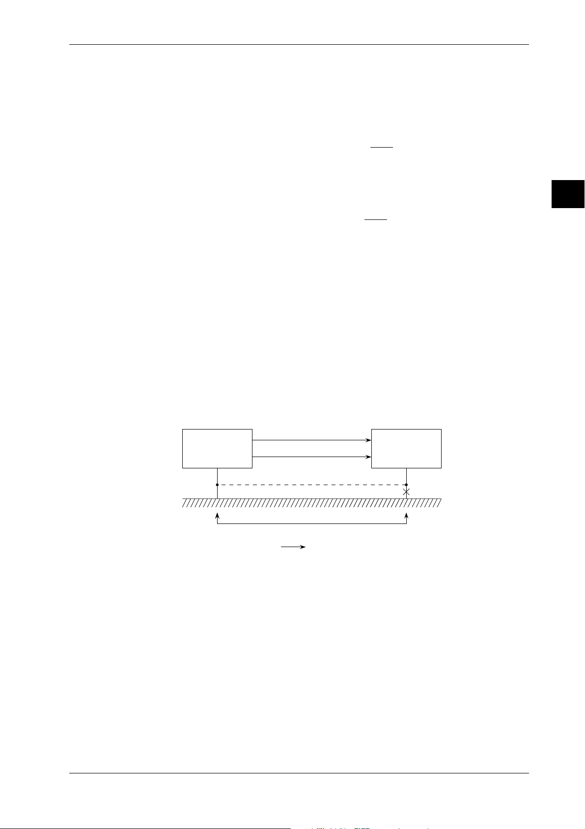
3.11 Countering Noise
In the figure on the previous page, due to common mode voltage ECM, noise currents i1 and i
flow through the impedance to grounds Z1 and Z2 and coupling impedance Z3, resulting in the
generation of normal mode noise E
noise is converted to normal mode noise. The amp is equipped with a built-in filter and in case of
output E
the normal mode noise will be eliminated. This rate of conversion is called the
O
common mode rejection ratio and expressed by the following equation.
• Common mode rejection ratio
Since the actual CMRR is expressed using the ratio of an error component output caused by
common mode noise to common mode noise, it contains the normal mode rejection ratio (NMRR)
expressed by the following equation.
• Normal mode rejection ratio
The NMRR is a value that shows the ability to reject the output error (normal mode noise
component: E
) by normal mode noise. Thus, this is also a very important value which shows
NM
the resistance-to-noise characteristics of the measuring instrument.
Basics of Anti-Noise Measures (part 2)
Decreasing and Increasing Impedance
As described in the previous section, conversion of common mode noise into normal mode noise
causes an error in the measured output. In other words, prevention of such a conversion is the key
to anti-noise measures. As can be understood from the previous section, it is important to take the
following measures to reduce normal mode noise.
· reduce the wiring resistances R
· increase the coupling impedance of common mode voltage E
These are called the decrease and increase of impedance as basics of anti-noise measures.
In the above discussions, anti-noise measures have been described on the assumption that
common mode noise has already been given. In real applications, common mode noise often
occurs owing to grounding resistance as shown in the figure below.
H
Signal source
L
between input terminals H and L. Like this, common mode
NM
(CMRR)=20Log
(NMRR)=20Log
and R2, including the resistance of the wires.
1
One-point grounding
E
O
(dB)
E
C M
E
O
(dB)
E
N M
The instrument
CM
2
3
Installation and Wiring
.
Grounding resistance and E
In such a case, perform one-point grounding as indicated by the dotted line, as an extreme
example of decreasing impedance, to equalize the potentials of the signal source and the
instrument. Rejecting common mode noise in this way is the basics of anti-noise measures.
Anti-Noise Measures in the Instrument Itself
Pulse width modulation type A/D converter (PWM type A/D)
This instrument uses a feedback pulse width modulation type A/D converter and has the
following features:
• Linearity and stability are good because of the feedback effect.
• Integration type A/D converter ensures excellent noise suppression.
If the integration time is equal to the noise period, the positive and negative sides of the shaded
part in the figure below cancel each other out and thus the average value becomes zero.
IM DR232-01E
CM
Ground current
3-39
Page 85

3.11 Countering Noise
Balance each other
Input voltage (instantaneous value)
DC voltage (average value)
integration time
Normally, an integration time of 20ms (50Hz) or 16.7ms (60Hz) is selected depending on the
commercial power supply frequencies. A 100-ms integration mode is added to the instrument to
achieve superior noise rejection. However, when using the 100ms setting, the smallest
measurement interval is longer than in case of the 20ms or 16.7ms setting. The integration effect
enables the PWM A/D converter to perform the following two functions.
• Rejection of frequency determined by the reciprocal of the integration time and frequencies
which are whole multiples of that frequency;
• First-order lag filter provided with cut-off frequency proportional to the reciprocal of the
integration time.
The following table compares the integration times of 16.7ms, 20ms and 100ms.
Integration time Rejection frequency Cut-off frequency Remarks
16.7ms n×60Hz approx. 19Hz for 60Hz
20.0ms n×50Hz approx. 16Hz for 50Hz
100.0ms n×10Hz approx. 3.2Hz for both 50Hz/60Hz
n=1,2,3...
As shown in the table, the merit of 100.0-ms integration is not only that it applies to both 50 and
60Hz, but also that it provides a low cut-off frequency as the first-order lag filter and improves
the noise rejection ability.
The following figure shows the calculation values of the NMRR for three integration times and an
example of actual measurement of the NMRR for a 100-ms integration signal.
• Calculated values of NMRR • Example of actual measurement of NMRR
(100ms)
0
-10
-20
-30
dB
-40
-50
-60
-70
100ms
5
10
Frequency (Hz)
20.0ms
16.7ms
20
50
100 200
Frequency (Hz)
Noise Filter
This instrument is equipped with a low-pass filter (cutoff-frequency of 10Hz (for both 50/60 Hz),
50Hz,60Hz) which functions as a way of noise rejection. Also exponential averaging functions as
a noise filter.
Anti-Noise Measures: Applications
Practical Measures
• Reducing noise itself
The basics of this practical measures dictates using the instrument in conditions where noise is
suppressed as much as possible.
• for power lines: an increase of impedance;
Separate the power lines for noise source equipment (inverter, thyristor, etc.) from those for
the measuring instrument.
3-40
IM DR232-01E
Page 86

3.11 Countering Noise
• for input lines: an increase of impedance;
Always separate the input line from the noise source lines (power and alarm lines).
Step 1 : Install a separator.
Separator
*
Signal
lines
Special class 3 ground
Power
lines
(10Ω or less)
Step 2 : Keep the signal cables at least 15cm above the power lines using a bracket.
If the power lines are not shielded, the operating voltage is 220V or less, and the operating
current is 10A or more, the distance between the signal cables and power cords must be
60cm or more.
Signal lines*
3
Installation and Wiring
Power
lines
at least
15 cm
Step 3 : Leave a clearance of at least 15 cm between the signal lines and power lines.
If the power lines are not shielded, the operating voltage is 220V or less, and the operating
current is 10A or more, the distance between the signal cables and power cords must be
60cm or more.
at least 15 cm
*
Signal
lines
Power
lines
Step 4 : Lay the signal lines at right angles to the power lines.
If the power lines are not shielded, separate the signal lines and power lines where they cross
using steel sheeting at least 1.6mm thick.
Signal lines
*
1.6mm
Power lines
* Separate analog signal lines and communication cables in the same manner as from power
cords.
IM DR232-01E
• When there is influence from a magnetic or electrical field: an increase of
impedance
Step 1 : Keep the noise source as far away as possible.
I
2,400
Magnetic field strength
Example
H
r=1m
H =
=
2πr
I=2,400A
= 400
A/m
6
The influence of the external magnetic field on the measuring instrument: 400A/m or less.
3-41
Page 87

3.11 Countering Noise
Step 2 : Change the position of the noise source.
A) Leakage magnetic flux of transformer:
Φ = strong
Φ = weak
Move the instrument to a location
where the influence from magnetic
flux is weak.
B) Sparks
spark
strong electromagnetic
radiation
weak electrogmagnetic
radiation
Move the instrument to a location
where the influence from electromagnetic radiation is weak.
• Grounding: a decrease of impedance
The grounding method is the point of common mode noise suppression.
Equipment
under
measurement
(EUM)
The instrument
3-42
ec ec'
The difference in the potential to the ground between EUM
and the instrument may cause a ground current, resulting in noise.
Equalize the potentials to the ground so
that the common mode noise becomes zero.
One-point grounding Potential equalization
EUM The instrument EUM The instrument
or
(if grounding is difficult)
The basic means to obtain stable measurement is to set the circuit potential with proper
grounding. Thus, potential equalization is the means to be adopted only when grounding is
impossible.
IM DR232-01E
Page 88

3.11 Countering Noise
• Shielded and twisted pair (prevention of electromagnetic coupling): an increase
of impedance
If it is difficult to keep the noise source away from the measuring instrument due to space
limitations, the use of a shielded twisted pair is effective.
• electrostatic coupling can be completely cut off by shielding;
• for a magnetic field, shielding with a magnetic material (iron, permalloy, etc.) can be
employed. However, there are many restrictions on this use and perfect shielding is
impossible. Therefore, use of a twisted pair is preferable.
Voltage e
induced by the coil is proportional to the area of the coil.
m
=> The smaller the area of the coil becomes, the smaller the noise becomes.
Coil
Magnetic field Φ
e
m
If the directions of coils 1 and 2 are reversed by twisting, as shown, if the areas of the two coils
are equal, the induced voltages of the coils offset each other and total induced voltage em
becomes zero.
e
m
coil 1 coil 2
The above two principles are combined as a twisted pair.
Even though a shielded twisted pair is used, a proper grounding method is still important.
Signal
source
twisted pair shield
Connected
equipment
3
Installation and Wiring
IM DR232-01E
If the signal source is not grounded
Power
source
twisted pair shield
connected
equipment
Ground the signal cable shields collectively but separately from the power line ground. If the
separation of grounds is impossible, use the guard terminal.
3-43
Page 89

3.11 Countering Noise
• Insertion of noise filter and noise killer
If the influence from noise cannot be eliminated by the methods described before, use noise
filter or noise killer.
Power line noise rejection
Step 1 : Insert an isolation transformer into the power line.
Increasing impedance to high frequency
Power
supply
100V AC
1:1
with shield, which is grounded
The
instrument
(Most of the noise is
high-frequency noise)
Step 2 : Insert a power line noise filter (available on the market)
High frequency noise is divided by decreasing impedance to ground through C and
increasing impedance through L.
Power
supply
100V AC
L
C
The
instrument
Note 1:Ground the noise filter and the recorder in common.
Note 2:Since insertion of a noise filter increases the by-pass current (regarded as leakage
current), make sure that the leakage current is within the specified value.
• When the noise contains wide frequency components
While one-point grounding is effective at a low frequency, it sometimes forms a loop and
has an adverse effect on a high frequency.
Ex: Connecting a power meter and the recorder grounded at one point to an inverter
Noise source
(inverter, etc.)
The power meter leaks the high-frequency noise component to the
ground and that noise flows back to the DA100 side.
Noise source
(inverter, etc.)
Reverse flow of high-frequency to the recorder is thus suppressed.
AC power meter
The instrument
AC power meter
The instrument
(high impedance at high frequency)
High-frequency noise
(reverse flow)
blocking of reverse flow
Ferrite beads
Noise
One-point
grounding
• Input noise rejection
If input noise cannot be rejected by means of one-point grounding or 100-ms integration,
insert capacitor or ferrite beads as they are effective in rejecting pulse noise.
Step 1 : Connect a capacitor between the L input and ground.
3-44
H
The instrument
L
C
Use a capacitor from a hundred
to thousands of pF which can
withstand high voltages and
must be grounded.
Step 2 : Rejection of pulse noise when grounding is impossible.
C
Ferrite beads
Insert the ferrite beads as necessary.
H
The instrument
L
Use a capacitor from a hundred
to thousands of pF.
IM DR232-01E
Page 90

3.11 Countering Noise
• Relay noise suppression
<DC relay>
To prevent noise and protect the contact,
connect the diode to the relay coil terminal
directly.
In addition to the above measure, reduce
the rated voltage of the relay circuit as
much as possible for higher reliability.
It is necessary to choose a diode that
matches the relay. Generally, a diode
whose rated rectifying current is at least
three times the current flowing through
the relay coil must be used.
And the rated reverse voltage must be at
least three time the operating voltage.
(Note) Across the relay or solenoid coil, a counter-electromotive force is produced by an
inductive load. This phenomenon may damage the contact or, as the noise source,
cause a malfunctioning of the equipment, and have an unfavorable effect on the
entire system.
<AC relay>
If a relay contact is connectd to the input
of the system components, apply the
measure shown in the figure at the right
to the relay coil. Otherwise, a counter electromotive force produced across the
coil may be induced on the contact side
through the relay's internal coupling or
coupling between the lines, and may
cause a malfunctioning of the equipment.
Dc external
power supply
Contact
Diode
connect to the relay
coil terminal (socket)
(
R
Re=Relay coil's DC resistance
directly.
Relay
the relay coil rating must
(
be as low as possible.
Surge suppresser circuit
connect to the
relay socket
(
terminal directly.
C=0.01 to 1µF
C
Must withstand a voltage
of at least three times
R
the operating voltage.
R=0.3Re to 1Re
)
)
3
Installation and Wiring
)
• Others (isolation from noise source: for hot line measurement)
(Hot line)
Power transistor
Anti-Noise Measures for PC Connection
When connecting the instrument to a PC, it is recommended to apply ferrite cores (e.g.
ZCAT3035-1303 from TDK) to the interface cable as a noise countering measure. Apply a ferrite
core on both sides of the cable as shown below, when the noise persists, apply more ferrite cores.
Personal
computer
Ferrite core
At low temperatures
(Vcc)
At high temperatures
Function
grounding
terminal
Mylar isolation film
Wrap
Adhesive copper
foil tape
Adhesion
IM DR232-01E
3-45
Page 91

4.1 Using the AUTO Display
D I S P M O D E
E S C
P R I N TF U N C
I N S D E L
R A N G E A L A R M
S E TC H A R T E N T E R
R E C O R D
F E E D
M. F U N C 1
M. F U N C 2
AUTO Display for the Main Display
1 Select the main display using the DISP key. Direct the arrow mark on the Sub-display upward.
2 Select “AUT” using the MODE key.
Sub-display 1
003 0.0045V 004 0.0931V
AUT
AUTO Display for Sub-display 1
1 Select sub-display 1 using the DISP key. Direct the arrow mark on the Sub-display leftward.
2 Select “AUT” using the MODE key.
Sub-display 1
004 0.0926V 005 0.0824V
AUT
AUTO Display for Sub-display 2
1 Select sub-display 2 using the DISP key. Direct the arrow mark on the Sub-display downward.
2 Select “AUT” using the MODE key.
Sub-display 1
005 0.8210V 006 0.0095V
AUT
4
Setting the Monitor Mode Display
IM DR232-01E
4-1
Page 92

4.1 Using the AUTO Display
AUTO Display for the Main Display
Channel No.
The first three characters are used for displaying the channel number. Delete “The first character
always displays “0”.” “A” will be displayed in the case of optional computation channels.
If you selected TAG at the channel No./TAG setting in the set-up mode (refer to 10.2 on page 10-
4), the assigned tag will appear for each channel.
• The first 7 characters of the TAG setting will be displayed;
• If the TAG setting consists of only spaces, the channel number will be displayed instead;
• If the first character of the TAG setting is a space, the 2nd to 8th character will be displayed.
Difference between Channels (delta)
One character is used to let you know that difference between channels (delta) is displayed.
However, it will not be displayed in the case of optional computation channels.
Only if you selected the difference between channels (delta) as the input type, “d” will be
displayed here.
Alarms
Two characters are used for displaying alarms. One channel is used in the case of optional
channels.
When an alarm occurs, the kind of alarm will be displayed. When in one channel several alarms
occur at the same time, the priority of display becomes H > L > dH > dL > RH > RL. For details
on H, L, dH, dL, RH and RL alarms, refer to page 8-2.
Measurement Values
Seven characters are used for displaying the measurement values. The decimal point uses up one
character. Nine channel is used in the case of optional computation channels.
When a measurement value does not reach the following value, “–
” will be displayed.
*****
• DC voltage: a minimum value of the measuring range – (max. value – min. value) × 0.05
• TC/RTD: min. value of the measurement range –10°C
• Linear scaling: –32000, or a minimum value of the recording span – (max. value – min. value)
× 0.05
When a measurement value exceeds the following value, “+
” will be displayed.
*****
• DC voltage: a maximum value of the measuring range + (max. value – min. value) × 0.05
• TC/RTD: min. value of the measurement range +10°C
• Linear scaling: +32000, or a maximum value of the recording span + (max. value – min. value)
× 0.05
If the input module is not connected properly, “ XXXXXX” will be displayed.
While waiting for an input signal “ OOOOOO” will be displayed.
Engineering Units
If the channel number has been selected to appear on the display, six characters are used for
displaying engineering units. If TAG has been selected to appear on the display, only three
characters are used for displaying units. Only the first three characters of the unit setting will then
be displayed, even if the first character of the unit setting is a space.
When “ XXXXXX” or “ OOOOOO” are displayed as measurement value, no engineering unit
will be displayed.
4-2
001
Difference between channels
Channel No.
1st digit: unit No.
2nd digit: slot No.
3rd digit: channel No. (in units of 1)
"A" will be displayed in the case of optional computation channels.
Alarm
V0.0467 H d
Engineering unit
Measurement value
Others
If you selected “SKIP” as the input type, that channel will not be displayed.
When the input type of all channels is set to “SKIP”, “***ALL SKIP***” will be displayed.
IM DR232-01E
Page 93

4.1 Using the AUTO Display
AUTO Display for Sub-display 1
Data of two channels are displayed here simultaneously.
Channel No., Difference between Channels (delta), Alarms, Measurement Values
Same as for the main display.
Engineering Units
If the channel number has been selected to appear on the display, the first four characters of the
unit setting are used for displaying engineering units. If TAG has been selected to appear on the
display or when “ XXXXXX” or “ OOOOOO” are displayed as measurement value, no
engineering unit will be displayed.
Selected Display Mode (refer to page 4-1 for procedure)
This only appears on sub-display 1 when monitoring. The arrow shows to which display the
display mode refers.
004d L 0.0926V 005 0.0824V
Alarm
Difference between channels
Channel No.
1st digit: unit No.
2nd digit: slot No.
3rd digit: channel No. (in units of 1)
Engineering unit
Measurement value
A will be displayed in the case of optional
computation channels.
AUT
Selected display mode
Others
Same as for the main unit.
AUTO Display for Sub-display 2
Data of two channels are displayed here simultaneously.
Channel No., Difference between Channels (delta), Alarms, Measurement Values,
Engineering Units and Selected Display Mode
Same as for the sub-display 1.
Others
Same as for the sub-display 1.
Points to Note when Using the AUTO Display
• When all three displays are set to AUTO display, the main display will start displaying data of
the channel with the smallest channel number, on sub-display 1 data of the next two channels
will be displayed, while on sub-display 2 data of the next two channels will be displayed. When
the data are updated, the display will be replaced with data of the next, consecutive, channel.
• When the input type of all channels is set to “SKIP”, then depending on the display as
described below, “***ALL SKIP***” will be displayed.
• When the main display is set to AUTO display, then this will be displayed settings on the
main display, regardless of the settings of sub-display 1 and 2.
• When sub-display 1 is set to AUTO display, and the main display is set to any other mode
than AUTO, then this will be displayed on sub-display 1, regardless the setting of subdisplay 2.
• When sub-display 2 is set to AUTO display, and the main display is set to any other mode
than AUTO, and sub-display 1 to any other mode than AUTO, then this will be displayed on
sub-display 2.
• When on any of the main, sub-display1 or sub-display 2 “***ALL SKIP***” appears, other
displays which may have been set to AUTO will turn blank. Only the selected display mode
on sub-display 1 and the status display will appear.
4
Setting the Monitor Mode Display
IM DR232-01E
4-3
Page 94

4.2 Using the MANUAL Display
D I S P
M O D E
E S C
P R I N TF U N C
I N S D E L
R A N G E A L A R M
S E TC H A R T E N T E R
MANUAL Display for the Main Display
1 Select the main display using the DISP key.
2 Select “MAN” using the MODE key.
Sub-display 1
002 0.0034V 003 0.0920V
3 Select the required channel using the keys.
Main display
001
V0.0057
MANUAL Display for Sub-display 1
1 Select sub-display 1 using the DISP key.
2 Select “MAN” using the MODE key.
Sub-display 1
002 0.0422V 003 0.0726V
R E C O R D
F E E D
M. F U N C 1
M. F U N C 2
MAN
MAN
3 Select the right or left channel using the keys. A dash [—] will appear below the unit
number of the selected channel.
4 Select the required channel using the
keys.
Sub-display 1
006 0.0892V 003 0.0726V
MAN
MANUAL Display for Sub-display 2
1 Select sub-display 2 using the DISP key.
2 Select “MAN” using the MODE key.
Sub-display 1
005 0.0931V 006 0.0092V
MAN
3 Select the right or left channel using the keys. A dash [—] will appear below the unit
number of the selected channel.
4 Select the required channel using the
keys.
Sub-display 2
009 1.0075V 008 0.0154V
4-4
IM DR232-01E
Page 95

4.2 Using the MANUAL Display
MANUAL Display for the Main Display
Channel No., Difference between Channels (delta) and Alarms
Same as for the AUTO display (refer to page 4-2).
Measurement Values
Same as for the AUTO display (refer to page 4-2), except for the following.
When the input type of the channel is set to “SKIP”, then “SKIP” will be displayed.
When the channel other than the channel of the input module is selected, “- - - - - -” appears.
Engineering Units
Same as for the AUTO display (refer to page 4-2), except for the following.
When the input type of the channel is set to “SKIP”, then no engineering unit will be displayed.
MANUAL Display for the Sub-display 1 and 2
Data of two channels are displayed here simultaneously on each display.
Channel No., Difference between Channels (delta), Alarms and Selected Display
Mode
Same as for the AUTO display (refer to page 4-3).
Measurement Values
Same as for the AUTO display (refer to page 4-3), except for the following.
When the input type of the channel is set to “SKIP”, then “SKIP” will be displayed.
When the channel other than the channel of the input module is selected, “- - - - - -” appears.
Engineering Units
Same as for the AUTO display (refer to page 4-3), except for the following.
When the input type of the channel is set to “SKIP”, then no engineering unit will be displayed.
4
Setting the Monitor Mode Display
IM DR232-01E
4-5
Page 96

4.3 Using the PAGE Display
D I S P
M O D E
E S C
P R I N TF U N C
I N S D E L
R A N G E A L A R M
S E TC H A R T E N T E R
R E C O R D
F E E D
M. F U N C 1
M. F U N C 2
1 Select the main display using the DISP key.
2 Select “PGE” using the MODE key.
Sub-display 1
002 0.1936V 003 0.0995V
PGE
3 Select the required set of five channels (page) using the keys.
Display
006
007 0.0197V 008 0.0074V
V0.0173
PGE
009 0.0162V 010 0.0102V
PAGE Display for the Main Display
When this display is selected, the measurement values of five consecutive channels will be
displayed using sub-display 1 and 2 also.
Channel No., Difference between Channels (delta) and Alarms
Same as for the AUTO display (refer to page 4-2).
Measurement Values
Same as for the AUTO display (refer to page 4-2), except for the following.
When the input type of the channel is set to “SKIP”, then “SKIP” will be displayed.
When the channel other than the channel of the input module is selected, “- - - - - -” appears.
Engineering Units
Same as for the AUTO display (refer to page 4-2), except for the following.
When the input type of the channel is set to “SKIP”, then no engineering unit will be displayed.
PAGE Display for the Sub-display 1 and 2
In combination with the page display of the main display, data of two channels are displayed here
simultaneously on each display. Other display modes cannot be selected.
Channel No., Difference between Channels (delta), Alarms and Selected Display Mode
Same as for the AUTO display (refer to page 4-3).
Measurement Values
Same as for the AUTO display (refer to page 4-3), except for the following.
When the input type of the channel is set to “SKIP”, then “SKIP” will be displayed.
When the channel other than the channel of the input module is selected, “- - - - - -” appears.
Engineering Units
Same as for the AUTO display (refer to page 4-3), except for the following.
When the input type of the channel is set to “SKIP”, then no engineering unit will be displayed.
4-6
IM DR232-01E
Page 97

4.4 Using the ALARM SEARCH Display
D I S P
M O D E
E S C
P R I N TF U N C
I N S D E L
R A N G E A L A R M
S E TC H A R T E N T E R
ALARM SEARCH Display for the Main Display
1 Select the main display using the DISP key.
2 Select “SER” using the MODE key.
Sub-display 1
003 0.0054V 004 0.0319V
ALARM SEARCH Display for Sub-display 1
1 Select sub-display 1 using the DISP key.
2 Select “SER” using the MODE key.
Sub-display 1
004 H 0.0269V 005 RH 0.0248V
ALARM SEARCH Display for Sub-display 2
1 Select sub-display 2 using the DISP key.
2 Select “SER” using the MODE key.
Sub-display 1
005 0.2108V 006 0.0951V
R E C O R D
F E E D
M. F U N C 1
M. F U N C 2
4
SER
Setting the Monitor Mode Display
SER
SER
ALARM SEARCH Display for the Main Display
Only the channels in which an alarm occurred, will be displayed. When an alarm occurs in several
channels, the channels will be displayed consecutively.
Channel No., Difference between Channels (delta), Alarms, Measurement Values
and Engineering Units
Same as for the AUTO display (refer to page 4-2).
Others
When the input types of all channels are set to “SKIP” or no alarms occur, “***NO ALARM***”
will be displayed.
ALARM SEARCH Display for the Sub-display 1 and 2
Only the channels in which an alarm occurred, will be displayed. Two channels will be displayed
on each sub-display.
Channel No., Difference between Channels (delta), Alarms, Measurement Values,
Engineering Units and Selected Display Mode
Same as for the AUTO display (refer to page 4-3).
IM DR232-01E
4-7
Page 98

4.4 Using the ALARM SEARCH Display
Points to Note when Using the ALARM SEARCH Display
• When all three displays are set to ALARM SEARCH display, the main display will start
displaying data of the channel with the smallest channel number, on sub-display 1 data of the
next two channels will be displayed, while on sub-display 2 data of the next two channels will
be displayed. When the data are updated, the display will be replaced with data of the next,
consecutive, channel.
• When the input type of all channels is set to “SKIP”, then depending on the display settings as
described below, “***NO ALARM***” will be displayed.
• When the main display is set to ALARM SEARCH display, then this will be displayed on the
main display, regardless the settings of sub-display 1 and 2.
• When sub-display 1 is set to ALARM SEARCH display, and the main display is set to any
other mode than ALARM SEARCH, then this will be displayed on sub-display 1, regardless
the setting of sub-display 2.
• When sub-display 2 is set to ALARM SEARCH display, and the main display is set to any
other mode than ALARM SEARCH, and sub-display 1 to any other mode than ALARM
SEARCH, then this will be displayed on sub-display 2.
• When on any of the main, sub-display1 or sub-display 2 “***NO ALARM***” appears,
other displays which may have been set to ALARM SEARCH will turn blank. Only the
selected display mode on sub-display 1 and the status display on sub-display 2 will appear.
4-8
IM DR232-01E
Page 99

4.5 Using the BARGRAPH Display
M O D E
D I S P
E S C
P R I N TF U N C
I N S D E L
R A N G E A L A R M
R E C O R D
F E E D
M. F U N C 1
S E TC H A R T E N T E R
M. F U N C 2
1 Select the sub-display 1 using the DISP key.
2 Select “BAR” using the MODE key.
Display
003
- 1.5000> < 2.0000
V0.0172
BAR
004 0.0153V 005 0.0123V
Bargraph Display
Sub-display 1 can be turned into a bargraph display.
The measurement data on the main display are displayed as a bargraph on sub-display 1. The
bargraph shows a graph corresponding to the measurement value, showing the recording span
divided into 40 equal parts. The left side of the bargraph shows the left span, the right side of the
bargraph shows the right span. When you are using the linear scaling function, the left and right
side of the bargraph show the left scaling and right scaling value respectively. Engineering units
are not displayed.
When the main display shows “SKIP”, “***ALL SKIP***”, “NO ALARM”, “OOOOOO”,
“XXXXXX”, or “- - - - - -” the bargraph will not appear. Only the selected display mode will
appear.
4
Setting the Monitor Mode Display
IM DR232-01E
4-9
Page 100

4.6 Using the ALARM STATUS Display
M O D E
D I S P
E S C
P R I N TF U N C
I N S D E L
R A N G E A L A R M
R E C O R D
F E E D
M. F U N C 1
S E TC H A R T E N T E R
M. F U N C 2
ALARM STATUS Display for Sub-display 1
1 Select the sub-display 1 using the DISP key.
2 Select “ALM” using the MODE key.
Sub-display 1
001
3 Select the range to be displayed in blocks of 10 channels.
Sub-display 1
011
ALARM STATUS Display for Sub-display 2
1 Select the sub-display 2 using the DISP key.
2 Select “ALM” using the MODE key.
Sub-display 1 and 2
001
001
3 Select the range to be displayed in blocks of 10 channels.
Sub-display 1 and 2
001
011
ALM
ALM
ALM
ALM
Alarm Status Display
The status of alarms can be displayed on sub-display 1 and 2.
On each sub-display the alarms of maximum 30 channels can be monitored which also depends
on the number of input channels. The display shows “
occurred, and shows “
” for channels where an alarm has occurred. The relation between the
” for channels where no alarm has
alarm status display and channel number is as shown below.
001
Alarm status of channel 3
Alarm status of channel 2
Alarm status of channel 1
Channel No. (fixed to 1 in units of 1)
Slot No.
Unit No.
Channel 10
"A" will be displayed in the case of optional computation channels.
Channel 12
Channel 11
Channel 21
Channel 20
Channel 30
021
Alarm status of channel 22
Alarm status of channel 21
Channel 30
4-10
IM DR232-01E
 Loading...