

Page 1
User’s
Manual
Model DO202G [Style: S2],
DO202S [Style: S3]
2-wire Dissolved Oxygen Transmitter
IM 12J05C01-01E
IM 12J05C01-01E
4th Edition
Page 2

TABLE OF CONTENTS
PREFACE
1. INTRODUCTION AND GENERAL DESCRIPTION ......................................... 1-1
1-1. Instrument check .................................................................................... 1-1
1-2. Application ............................................................................................... 1-3
2. GENERAL SPECIFICATIONS ......................................................................... 2-1
2-1. Specifications .......................................................................................... 2-1
2-2. Performance specifications ..................................................................... 2-2
2-3. Model and suffix codes ............................................................................ 2-5
2-4. Control Drawing of DO202S mA HART
®
Specification (IECEx) ............... 2-6
2-5. Control Drawing of DO202S mA HART® Specification (ATEX) ................ 2-7
2-6. Control Drawing of DO202S mA HART® Specification ............................. 2-8
(FM Intrinsically safe design)
2-7. Control Drawing of DO202S mA HART® Specification Specification ...... 2-9
(FM Non-incendive design)
2-8. Reserved for DO202S mA HART® Specification (CSA) ......................... 2-10
2-9. Control Drawing of DO202S FF/PB Specification (IECEx) ......................2-11
2-10. Control Drawing of DO202S FF/PB Specification (ATEX) .................... 2-12
2-11. Control Drawing of DO202S FF/PB Specification ................................ 2-13
(FM Intrinsically safe Entity)
2-12. Control Drawing of DO202S FF/PB Specification ................................ 2-15
(FM Intrinsically safe FISCO)
2-13. Control Drawing of DO202S FF/PB Specification ................................ 2-17
(FM Non-incendive Entity)
2-14. Control Drawing of DO202S FF/PB Specification ................................ 2-18
(FM Non-incendive FNICO)
2-15. Reserved for DO202S FF/PB Specification (CSA) ............................... 2-19
3. INSTALLATION AND WIRING ........................................................................ 3-1
3-1. Installation and dimensions ..................................................................... 3-1
3-1-1. Installation site ......................................................................................................3-1
3-1-2. Mounting methods ................................................................................................3-1
3-2. Wiring of power supply ............................................................................ 3-3
3-2-1. General precautions .............................................................................................3-3
3-2-2. Connection of the power supply ...........................................................................3-3
3-2-3. Switching the instrument on .................................................................................3-3
3-2-4. Preparation ...........................................................................................................3-3
3-2-5. Cables, terminals and glands ...............................................................................3-3
3-3. Wiring of sensors ..................................................................................... 3-3
3-3-1. Wiring the standard galvanic sensor ....................................................................3-3
3-3-2. Wiring other galvanic sensors ..............................................................................3-4
3-3-3. Wiring polarographic sensors ...............................................................................3-4
3-3-4. Wiring sensors with Vp connector ........................................................................3-4
3-3-5.
3-3-6. Additional precautions for installations in hazardous areas .................................3-5
3-3-7. Installation in: Hazardous Area-Non-Incendive ....................................................3-5
Sensor cable connections using junction box (BA10) and extension cable (WF10)
..3-4
4. OPERATION; DISPLAY FUNCTIONS AND SETTING ................................... 4-1
4-1. Operator interface.................................................................................... 4-1
4-2. Explanation of operating keys ................................................................. 4-2
4-3. Passcode protection ................................................................................ 4-2
4-4. Display examples .................................................................................... 4-3
4-5. Display functions ..................................................................................... 4-3
5. PARAMETER SETTING .................................................................................. 5-1
5-1. Maintenance mode .................................................................................. 5-1
5-1-1. Manual activation of hold ......................................................................................5-1
5-1-2. Manual temperature adjustment ...........................................................................5-2
IM 12J05C01-01E
4th Edition: Oct. 2009(YK)
All Rights Reserved, Copyright © 2007, Yokogawa Electric Corporation
IM 12J05C01-01E
Page 3

5-1-3. Manual pressure adjustment ................................................................................5-2
5-2. Commissioning mode .............................................................................. 5-3
5-2-1. Output range .........................................................................................................5-3
5-2-2. Hold.......................................................................................................................5-4
5-2-3. Service ..................................................................................................................5-5
5-3. Notes for guidance in the use of service coded settings ......................... 5-6
5-3-1. Parameter specific functions ................................................................................5-6
5-3-2. Temperature functions ..........................................................................................5-6
5-3-3. Calibration functions .............................................................................................5-6
5-3-4. mA Output functions .............................................................................................5-8
5-3-5. User interface .......................................................................................................5-8
5-3-6. Communication setup .........................................................................................5-10
5-3-7. General ...............................................................................................................5-10
5-3-8. Test and setup mode ..........................................................................................5-10
6. CALIBRATION PROCEDURE......................................................................... 6-1
6-1. General .................................................................................................... 6-1
6-1-1. Calibration methods ..............................................................................................6-1
6-1-2. Diagnostic functions performed during calibration ...............................................6-1
6-2. Calibration procedure using air calibration method ................................. 6-2
6-2-1. Preparation ...........................................................................................................6-2
6-2-2. Procedure for air calibration .................................................................................6-2
6-3. Calibration procedure using water calibration method ............................ 6-3
6-3-1. Preparation ...........................................................................................................6-3
6-3-2. Calibration operation (water calibration method) ..................................................6-3
6-3-3. Procedure for water calibration .............................................................................6-3
6-4. Calibration procedure using manual calibration method ......................... 6-4
6-4-1. Preparation ...........................................................................................................6-4
6-4-2. Procedure for manual slope (sensitivity) calibration .............................................6-4
6-4-3. Procedure for manual zero (offset) calibration .....................................................6-5
7. MAINTENANCE .............................................................................................. 7-1
7-1. Overall dissolved-oxygen metering system ............................................. 7-1
7-1-1. Inspection and maintenance to be implemented periodically ...............................7-1
7-1-2. Inspection and maintenance to be implemented occasion ..................................7-1
7-2. Periodic maintenance for the EXA DO202 transmitter ............................ 7-1
8. TROUBLESHOOTING .................................................................................... 8-1
8-1. Measures in the case of transmitter operation failure.............................. 8-1
8-2. Measures in the case of failure (error) detection ..................................... 8-1
9. SPARE PARTS ................................................................................................ 9-1
APPENDIX 1. USER SETTINGS .........................................................................A1-1
A-1-1. User setting table ................................................................................A1-1
A-1-2. Configuration checklist for DO202 ......................................................A1-2
A-1-3. Hart process variables ........................................................................A1-2
A-1-4. Device description (DD) menu structure .............................................A1-3
APPENDIX 2. QUALITY INSPECTION ...............................................................A2-1
A-2-1. DO202G 2-Wire Dissolved Oxygen Transmitter ................................. A2-1
A-2-2. DO202S 2-Wire Dissolved Oxygen Transmitter .................................. A2-5
A-2-3. DO202G, DO202S Fieldbus Communication .................................... A2-10
A-2-4. DO202G, DO202S Profibus Communication .................................... A2-14
Customer Maintenance Parts List (for DO202G Style: S2) CMPL 12J05C01-02E
Customer Maintenance Parts List (for DO202S Style: S3) . CMPL 12J05C01-23E
Revision Record ........................................................................................................i
In this manual a
sign appears if it concerns the DO202G (S)-A, -N, -K.
mA
IM 12J05C01-01E
Page 4
PREFACE
DANGERDANGER
Electric discharge
The EXA analyzer contains devices that can be
damaged by electrostatic discharge. When servicing
this equipment, please observe proper procedures
to prevent such damage. Replacement components
should be shipped in conductive packaging. Repair
work should be done at grounded workstations using
grounded soldering irons and wrist straps to avoid
electrostatic discharge.
Installation and wiring
The EXA analyzer should only be used with equipment that meets the relevant international and
regional standards. Yokogawa accepts no responsibility for the misuse of this unit.
CAUTIONCAUTION
The instrument is packed carefully with shock
absorbing materials, nevertheless, the instrument
may be damaged or broken if subjected to strong
shock, such as if the instrument is dropped. Handle
with care.
Although the instrument has a weatherproof
construction, the transmitter can be harmed if it
becomes submerged in water or becomes excessively wet.
Do not use an abrasive material or solvent when
cleaning the instrument.
Do not modify the DO202 transmitter.
WARNING
WARNING
Electrostatic charge may cause an explosion hazard. Avoid any actions that cause the generation of
electrostatic charge, e.g., rubbing with a dry cloth.
Warning label
Notice
• This manual should be passed on to the end user.
• The contents of this manual are subject to change
without prior notice.
• The contents of this manual shall not be
reproduced or copied, in part or in whole, without
permission.
• This manual explains the functions contained in
this product, but does not warrant that they are
suitable the particular purpose of the user.
• Every effort has been made to ensure accuracy in
the preparation of this manual.
However, when you realize mistaken expressions
or omissions, please contact the nearest
Yokogawa Electric representative or sales office.
• This manual does not cover the special
specifications. This manual may be left unchanged
on any change of specification, construction
or parts when the change does not affect the
functions or performance of the product.
• If the product is not used in a manner specified
in this manual, the safety of this product may be
impaired.
Yokogawa is not responsible for damage to the
instrument, poor performance of the instrument
or losses resulting from such, if the problems are
caused by:
• Improper operation by the user.
• Use of the instrument in improper applications
• Use of the instrument in an improper environment
or improper utility program
• Repair or modification of the related instrument by
an engineer not authorized by Yokogawa.
Safety and Modification Precautions
• Follow the safety precautions in this manual when
using the product to ensure protection and safety
of the human body, the product and the system
containing the product.
Because the enclosure of the Dissolved Oxygen
transmitter Type DO202S-A, -P, -F are made of aluminium, if it is mounted in an area where the use of
category 1 G Zone 0 apparatus is required, it must
be installed such, that, even in the event of rare
incidents, ignition sources due to impact and friction
sparks are excluded.
IM 12J05C01-01E
Page 5
The following safety symbols are used on the prod-
uct as well as in this manual.
DANGERDANGER
This symbol indicates that an operator must follow
the instructions laid out in this manual in order
to avoid the risks, for the human body, of injury,
electric shock, or fatalities. The manual describes
what special care the operator must take to avoid
such risks.
DANGER
Warranty and service
Yokogawa products and parts are guaranteed free
from defects in workmanship and material under normal use and service for a period of (typically)
12 months from the date of shipment from the manufacturer. Individual sales organizations can deviate
from the typical warranty period, and the conditions
of sale relating to the original purchase order should
be consulted. Damage caused by wear and tear,
inadequate maintenance, corrosion, or by the effects
of chemical processes are excluded from this warranty coverage.
WARNINGWARNING
This symbol indicates that the operator must
refer to the instructions in this manual in order to
prevent the instrument (hardware) or software from
being damaged, or a system failure from occurring.
CAUTIONCAUTION
This symbol gives information essential for
understanding the operations and functions.
This symbol indicates Protective Ground Terminal
This symbol indicates Function Ground Terminal
(Do not use this terminal as the protective ground
terminal.)
This symbol indicates Alternating current.
This symbol indicates Direct current.
In the event of warranty claim, the defective goods
should be sent (freight paid) to the service department of the relevant sales organization for repair or
replacement (at Yokogawa discretion). The following
information must be included in the letter accompanying the returned goods:
• Part number, model code and serial number
• Original purchase order and date
• Length of time in service and a description of the
process
• Description of the fault, and the circumstances of
failure
• Process/environmental conditions that may be
related to the installation failure of the device
• A statement whether warranty or non-warranty
service is requested
• Complete shipping and billing instructions for return
of material, plus the name and phone number of
a contact person who can be reached for further
information
Returned goods that have been in contact with process fluids must be decontaminated/disinfected before
shipment. Goods should carry a certificate to this
effect, for the health and safety of our employees.
Material safety data sheets should also be included
for all components of the processes to which the
equipment has been exposed.
IM 12J05C01-01E
Page 6

ATEX Documentation
This procedure is only applicable to the countries
in European Union.
GB
All instruction manuals for ATEX Ex related products are available in English, German and French.
Should you require Ex related instructions in your
local language, you are to contact your nearest
Yokogawa office or representative.
DK
Alle brugervejledninger for produkter relateret
til ATEX Ex er tilgængelige på engelsk, tysk og
fransk. Skulle De ønske yderligere oplysninger
om håndtering af Ex produkter på eget sprog, kan
De rette henvendelse herom til den nærmeste
Yokogawa afdeling eller forhandler.
I
Tutti i manuali operativi di prodotti ATEX contrassegnati con Ex sono disponibili in inglese,
tedesco e francese. Se si desidera ricevere i manuali operativi di prodotti Ex in lingua locale, mettersi in contatto con l’ufficio Yokogawa più vicino o
con un rappresentante.
E
Todos los manuales de instrucciones para los productos antiexplosivos de ATEX están disponibles
en inglés, alemán y francés. Si desea solicitar las
instrucciones de estos artículos antiexplosivos en
su idioma local, deberá ponerse en contacto con
la oficina o el representante de Yokogawa más
cercano.
NL
Alle handleidingen voor producten die te maken
hebben met ATEX explosiebeveiliging (Ex)
zijn verkrijgbaar in het Engels, Duits en Frans.
Neem, indien u aanwijzingen op het gebied van
explosiebeveiliging nodig hebt in uw eigen taal,
contact op met de dichtstbijzijnde vestiging van
Yokogawa of met een vertegenwoordiger.
SF
Kaikkien ATEX Ex -tyyppisten tuotteiden käyttöhjeet ovat saatavilla englannin-, saksan- ja
ranskankielisinä. Mikäli tarvitsette Ex -tyyppisten
tuotteiden ohjeita omalla paikallisella kielellännne,
ottakaa yhteyttä lähimpään Yokogawa-toimistoon tai
-edustajaan.
P
Todos os manuais de instruções referentes aos
produtos Ex da ATEX estão disponíveis em Inglês,
Alemão e Francês. Se necessitar de instruções na
sua língua relacionadas com produtos Ex, deverá
entrar em contacto com a delegação mais próxima
ou com um representante da Yokogawa.
F
Tous les manuels d’instruction des produits ATEX
Ex sont disponibles en langue anglaise, allemande
et française. Si vous nécessitez des instructions
relatives aux produits Ex dans votre langue, veuillez
bien contacter votre représentant Yokogawa le plus
proche.
D
Alle Betriebsanleitungen für ATEX Ex bezogene Produkte stehen in den Sprachen Englisch,
Deutsch und Französisch zur Verfügung. Sollten
Sie die Betriebsanleitungen für Ex-Produkte in Ihrer
Landessprache benötigen, setzen Sie sich bitte mit
Ihrem örtlichen Yokogawa-Vertreter in Verbindung.
S
Alla instruktionsböcker för ATEX Ex (explosionssäkra) produkter är tillgängliga på engelska, tyska
och franska. Om Ni behöver instruktioner för dessa
explosionssäkra produkter på annat språk, skall Ni
kontakta närmaste Yokogawakontor eller representant.
GR
IM 12J05C01-01E
Page 7

SK
CZ
PL
SLO
LT
LV
EST
H
BG
RO
M
IM 12J05C01-01E
Page 8
1. INTRODUCTION AND GENERAL DESCRIPTION
Introduction 1-1
The Yokogawa EXA 202 is a 2-wire transmitter
designed for industrial process monitoring, measurement and control applications.
This user’s manual contains the information needed
to install, set up, operate and maintain the unit correctly. This manual also includes a basic troubleshooting guide to answer typical user questions.
Yokogawa can not be responsible for the performance of the EXA analyzer if these instructions are
not followed.
mA
DISSOLVED OXYGEN TRANSMITTER
MODEL
DO202
SUFFIX
II 1G
SUPPLY
OUTPUT
AMB.TEMP.
STYLE
No.
Made in Japan Tokyo 180-8750 JAPAN
24V DC
4 20mA DC
-10 55°C
R
LR81741 C
WARNING
Substitution of
components may impair
intrinsic safety
N200
DO202S-A
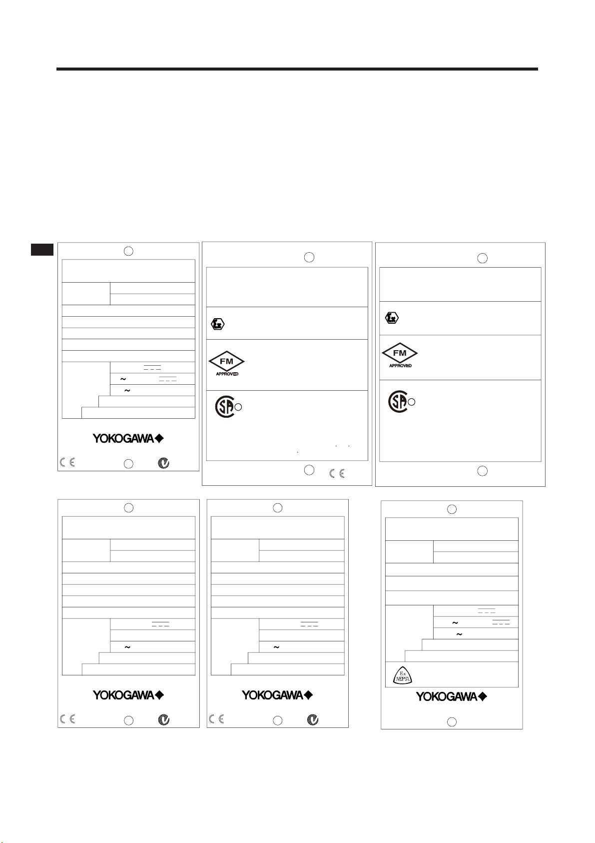
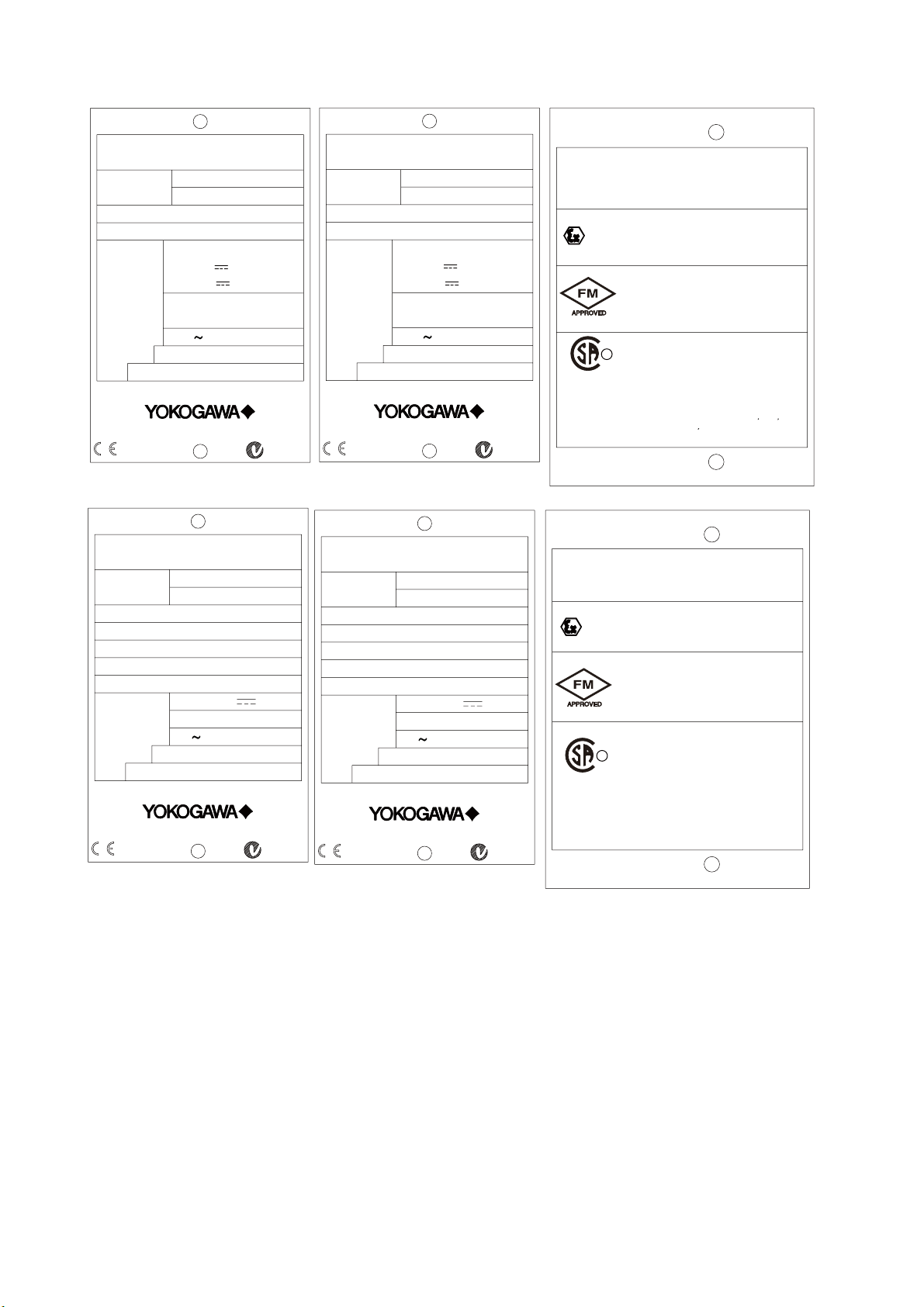
1-1. Instrument check
Upon delivery, unpack the instrument carefully and
inspect it to ensure that it was not damaged during shipment. If damage is found, retain the original
packing materials (including the outer box) and
then immediately notify the carrier and the relevant
Yokogawa sales office.
Make sure the model number on the nameplate
affixed to the side of the instrument agrees with
your order. Example of nameplate is shown below.
No. IECEx KEM 06.0055X
Zone 0 Ex ia IIC T4
Zone 0 Ex ia IIC T6 for Ta:40
IP65
SEE CONTROL DRAWING
No. KEMA 06ATEX0224 X
Ex ia IIC T4
Ex ia IIC T6 for Ta:40
SEE CONTROL DRAWING
IS CL I, DIV 1, GP ABCD
AND AEx ia IIC
T4
Type 4X
Install per CONTROL DRAWING
IKE030-A10 P.5 to P.6
CL I, DIV 1, GP ABCD
Ex ia IIC T4
Ex ia IIC T6 for Ta:40
SEE CONTROL DRAWING
IP65 Type 3S
AVERTISSEMENT
La substitution de composants
peut compromeltre la securite
intrinseque.
°C
°C
IP65
°C
0344
No. IECEx KEM 06.0055X
Ex nA[nL] IIC T4
Ex nA[nL] IIC T6 for Ta:40
IP65
SEE CONTROL DRAWING
No. KEMA 06ATEX0225
EEx nA[nL] IIC T4
II 3 G
EEx nA[nL] IIC T6 for Ta:40
IP65
SEE CONTROL DRAWING
NI CL I, DIV 2, GP ABCD AND
CL I, ZN 2, GP IIC
T4
Type 4X
Install per CONTROL DRAWING
IKE030-A10 P.7 to P.8
Ex nA[nL] IIC
NI CL I, DIV 2, GP ABCD
T4
R
T6 for Ta:40
LR81741 C
WARNING
Substitution of
components may
impair suitability
for class I, Division 2.
IP65 Type 3S
SEE CONTROL DRAWING
DO202S-N
°C
°C
°C
AVERTISSEMENT
La substitution de composants
peut rendre ce materiel
inacceptable pour les
emplacements de
Classe I, Division 2.
DISSOLVED OXYGEN TRANSMITTER
MODEL
DO202G-F
SUFFIX
SUPPLY
OUTPUT
AMB.TEMP.
9 TO 32VDC
FF-TYPE113
-10 55°C
STYLE
No.
Made in Japan Tokyo 180-8750 JAPAN
Figure 1-1. Nameplates
IM 12J05C01-01E
N200
DISSOLVED OXYGEN TRANSMITTER
MODEL
DO202G-P
SUFFIX
SUPPLY
OUTPUT
AMB.TEMP.
9 TO 32VDC
PROFIBUS-PA
-10 55°C
STYLE
No.
Made in Japan Tokyo 180-8750 JAPAN
N200
DISSOLVED OXYGEN TRANSMITTER
MODEL
SUFFIX
SUPPLY
OUTPUT
AMB.TEMP.
STYLE
No.
Made in Japan Tokyo 180-8750 JAPAN
DO202S-K
24V DC
4 20mA DC
-10 55°C
Cert No. GYJ081159X
Ex ia IIC T4
Ex ia IIC T6 for Ta:40
SEE USER’S MANUAL BEFORE USE
˚C
Page 9
1-2 Introduction
DISSOLVED OXYGEN TRANSMITTER
MODEL
DO202S-F
SUFFIX
SUPPLY
OUTPUT
AMB.TEMP.
FISCO
17.5VDC
or 24VDC
/380mA/5.32W
/250mA/1.2W
FF-TYPE111 or 511
Li=0 μH, Ci=220pF
-10 55°C
STYLE
No.
Made in Japan Tokyo 180-8750 JAPAN
0344
DISSOLVED OXYGEN TRANSMITTER
MODEL
DO202S-B
SUFFIX
SUPPLY
OUTPUT
AMB.TEMP.
9 TO 32VDC
FF-TYPE 113
-10 55°C
STYLE
No.
Made in Japan Tokyo 180-8750 JAPAN
Figure 1-2. Nameplates
N200
N200
DISSOLVED OXYGEN TRANSMITTER
MODEL
DO202S-P
SUFFIX
SUPPLY
OUTPUT
AMB.TEMP.
FISCO
17.5VDC
or 24VDC
/380mA/5.32W
/250mA/1.2W
PROFIBUS-PA
Li=0 μH, Ci=220pF
-10 55°C
STYLE
No.
Made in Japan Tokyo 180-8750 JAPAN
0344
DISSOLVED OXYGEN TRANSMITTER
MODEL
DO202S-D
SUFFIX
SUPPLY
OUTPUT
AMB.TEMP.
9 TO 32VDC
PROFIBUS-PA
-10 55°C
STYLE
No.
Made in Japan Tokyo 180-8750 JAPAN
N200
N200
FISCO field device
IECEx KEM 07.0029X
No.
Zone 0 Ex ia IIC T4
IP65
SEE CONTROL DRAWING
No.
KEMA 07ATEX0054 X
Ex ia IIC T4
II 1G
SEE CONTROL DRAWING
IP65
IS CL I, DIV 1, GP ABCD
AND AEx ia IIC
Type 4X
T4
Install per CONTROL DRAWING
IKE031-A10 P.5 to P.8
CL I, DIV 1, GP ABCD
R
Ex ia IIC T4
LR81741 C
WARNING
Substitution of
components may impair
intrinsic safety
SEE CONTROL DRAWING
IP65 Type 3S
DO202S-F/-P
FNICO field device
IECEx KEM 07.0029X
No.
Ex nA[nL] IIC T4
Ex nA[nL] IIC T6 for Ta:40
IP65
SEE CONTROL DRAWING
No.
KEMA 07ATEX0055
EEx nA[nL] IIC T4
II 3 G
EEx nA[nL] IIC T6 for Ta:40
IP65
SEE CONTROL DRAWING
NI CL I, DIV 2, GP ABCD AND
CL I, ZN 2, GP IIC
T4
Type 4X
Install per CONTROL DRAWING
IKE031-A10 P.9 to P.10
Ex nA[nL] IIC
NI CL I, DIV 2, GP ABCD
T4
R
T6 for Ta:40
IP65 Type 3S
LR81741 C
WARNING
Substitution of
components may
impair suitability
for class I, Division 2.
SEE CONTROL DRAWING
AVERTISSEMENT
La substitution de composants
peut rendre ce materiel
inacceptable pour les
emplacements de
Classe I, Division 2.
DO202S-B/-D
AVERTISSEMENT
La substitution de composants
peut compromeltre la securite
intrinseque.
°C
°C
°C
Note: Check that all the parts are present, including
mounting hardware, as specified in the option
codes at the end of the model number. For
a description of the model codes, refer to
Chapter 2 of this manual under General
Specifications.
Basic Parts List: Transmitter DO202
User’s Manual English
Optional mounting hardware when
specified (See model code)
IM 12J05C01-01E
Page 10

Introduction 1-3
1-2. Application
The EXA transmitter is intended to be used for continuous on-line measurement in industrial installations.
The unit combines simple operation and microprocessor-based performance with advanced self-diagnostics
and enhanced communications capability to meet the most advanced requirements. The measurement can
be used as part of an automated process control system. It can also be used to indicate dangerous limits of
a process, to monitor product quality, or to function as a simple controller for a BOD/COD system.
Yokogawa designed the EXA analyzer to withstand harsh environments. The transmitter may be installed
either indoors or outside because the IP65 (NEMA 4X) housing and cabling glands ensure the unit is adequately protected. The flexible polycarbonate window on the front door of the EXA allows pushbutton access
to the keypad, thus preserving the water and dust protection of the unit even during routine maintenance
operations.
A variety of EXA hardware is optionally available to allow wall, pipe, or panel mounting. Selecting a proper
installation site will permit ease of operation. Sensors should normally be mounted close to the transmitter
in order to ensure easy calibration and peak performance. If the unit must be mounted remotely from the
sensors, WF10 extension cable can be used up to a maximum of
box.
The EXA is delivered with a general purpose default setting for programmable items. (Default settings are
listed in Chapter 5). While this initial configuration allows easy start-up, the configuration should be adjusted
to suit each particular application. An example of an adjustable item is the type of sensor used. The EXA
can be adjusted for galvanic and polarographics sensors.
30 metres (100 feet) with a BA10 junction
To record such configuration adjustments, write changes in the space provided in APPENDIX 1 of this
manual. Because the EXA is suitable for use as a monitor, a controller or an alarm instrument, program
configuration possibilities are numerous.
Details provided in this user’s manual are sufficient to operate the EXA with all Yokogawa sensor
systems and a wide range of third-party commercially available probes. For best results, read this manual in
conjunction with the corresponding sensor user’s manual.
Yokogawa designed and built the EXA to meet the CE regulatory standards. The unit meets or exceeds
stringent requirements of EMC Directive 89/336/EEC, to assure the user of continued accurate performance
in even the most demanding industrial installations.
IM 12J05C01-01E
Page 11

1-4 Introduction
IM 12J05C01-01E
Page 12
2. GENERAL SPECIFICATIONS
General Specifications 2-1
2-1. Specifications
A. Input specifications
The DO202 accepts output from membrane covered
Dissolved Oxygen sensors. These sensors can be
Galvanic type, where the sensor generates its own
driving voltage or Polarographic type, where the sensor uses external driving voltage from the transmitter.
The input range is 0-50 A for Galvanic sensors and 01 A for Polarographic sensors. For temperature compensation the DO202 accepts Pt1000 (DO30 sensor)
and 22kNTC elements (OXYFERM and OXYGOLD
sensors)
B. Measuring range
- Dissolved Oxygen
: 0 - 50 ppm (mg Oxygen
per kg water);
0 - 1999 ppb (mg Oxygen
per 1000 kg water) and 0
- 600 % Saturation of Air
in Water.
- Temperature : -20 to 150ºC (-4 to 302ºF).
C. Temperature compensation
Automatic using Pt1000 or 22kNTC or
manual Range 0 - 100ºC (32 to 212 ºF)
D. Calibration
Semi-automatic one or two point calibration in air
or in water using solubility tables of ISO 5814.
The influence of pressure and salinity is taken
into account when these specifications are
entered. Also a two point manual calibration is
possible.
E. Transmission Signals
Isolated output of 4-20 mA DC, Burn up (21 mA)
or Burn dwon (3.6 mA when HART® comm. nonused, 3.9 mA when HART comm. used) or pulse
of 21 mA to signal failure.
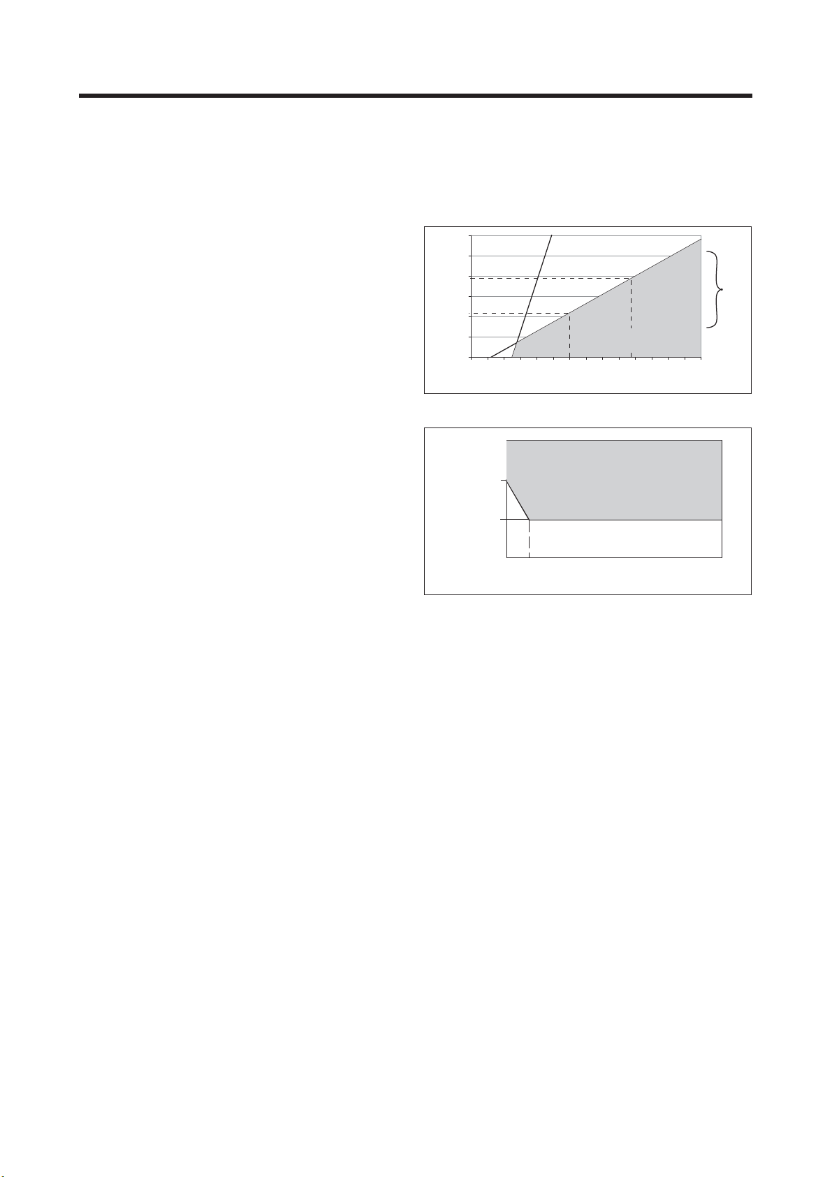
Note: The transmitter contains a switched
power supply. The transmitter requires a
minimum power voltage in order to work
correctly, which is dependant on the load.
Please refer to figures 2-1 and 2-2 for the
correct power supply
1200.0
1000.0
800.0
775.0
600.0
425.0
400.0
Load Resistance (Ω)
200.0
0.0
12 14 16 18 20 22 24 26 28 30 32 34 36 38 40
Figure 2-1. Supply voltage/ load diagram
17 Volts
14.5 Volts
4 mA
(limit for IS version)
Voltage (V)
22 mA
31.5 V
Terminal voltage (V)
4 mA 7 mA 20 mA
Output Current (mA)
Figure 2-2. Minimum terminal voltage at the DO202
I. Input isolation
1000 VDC
J. Shipping Details
Package size : W x H x D, 290 x 300 x 290
mm (11.5 x 11.8 x 11.5 inch)
Packed weight : approx. 2.5 kg (5lb)
1100.0
Range
Communication
230.0
F. Logbook
Software record of important events and
diagnostic data. Available through digital
communication.
G. Display
Custom liquid crystal display, with a main display
of 3 1/2 digits 12.5 mm high. Message display of
6 alphanumeric characters, 7 mm high.
H. Power supply
Nominal 24 volt DC loop powered system
DO202G-A : up to 40 volts
DO202S-A, -N: up to 31.5 volts
DO202G/S-F, -P: 9-24, 9-17.5 (FISCO) VDC /
26.0 mA
DO202S-B, -D: 9-32 VDC / 26.0 mA
IM 12J05C01-01E
Page 13
2-2 General Specifications
2-2. Performance specifications
A. Performance in ppm mode
- Linearity : ±0.05 ppm or ±0.8% FS,
whichever is greater
- Repeatability : ±0.05 ppm or ±0.8% FS,
whichever is greater
- Accuracy : ±0.05 ppm or ±0.8% FS,
whichever is greater
B. Performance in ppb mode
- Linearity : ±1 ppb or ±0.8% FS,
whichever is greater
- Repeatability : ±1 ppb or ±0.8% FS,
whichever is greater
- Accuracy : ±1 ppb or ±0.8% FS,
whichever is greater
C. Performance in Temperature
- Linearity : ±0.3ºC
- Repeatability : ±
0.1ºC
- Accuracy : ±0.3ºC
Note on performance specifications:
The specifications are at reference temperature
and with simulated inputs, because the
DO202G can be used with many different
sensors with their unique characteristics.
The following tolerance is added to above
performance.
mA output tolerance : ± 0.02 mA of
"4 - 20 mA"
D. Ambient temperature
Operating temperature -10 to 55ºC
(10 to 130ºF)
Storage temperature -30 to 70ºC
(-20 to 160ºF)
E. Humidity
10 to 90% RH non-condensing
F. Housing
Cast aluminum housing with chemically
resistant coating, cover with flexible
polycarbonate window. Case color is off-white
with moss green cover. Cable entry is through
two polyamide cable glands. Cable glands are
provides for wiring up to 2.5 mm.
G. Environmental protection
IP65, NEMA 4X.
H. Mounting
Pipe, wall or panel mounting using optional
hardware.
I. Data protection
EEPROM for configuration; Lithium battery for
clock.
J. Watchdog timer: Checks microprocessor.
K. Autoreturn
The transmitter returns into measuring mode
automatically when no keystroke is made for 10
minutes.
L. Operation protection
All three levels can be protected by a user
programmable 3 digit password
M. EMC Conformity standards
EN 61326-1 Class A, Table 2
(For use in industrial locations)
EN 61326-2-3
EN 61326-2-5 (pending)
CAUTION
This instrument is a Class A product, and it is
designed for use in the industrial environment.
Please use this instrument in the industrial
environment only.
N. Explosionproof type
Refer to Control Drawings.
mA
Item
Factory
Mutual (FM)
CENELEC
ATE X
Item
Factory
Mutual (FM)
FM Intrinsically safe Approval
Applicable standard: FM3600, FM3610, FM3810
Intrinsically Safe for Class I, Division 1, Groups ABCD
Class I, Zone 0, AEx ia IIC
Temp. Class: T4, Amb. Temp.: -10 to 55°C
Intrinsically Safe Apparatus Parameters
Vmax=31.5 V, Imax=100 mA,
Pmax=1.2 W, Ci=22 nF, Li=35 μH
FM Non-incendive safe Approval
Applicable standard: FM3600, FM3611, FM3810
Non-incendive Safe for Class I, Division 2,
Groups ABCD, Zone 2
Temp. Class: T4, Amb. Temp.: -10 to 55°C
Non-incendive Safe Apparatus Parameters
Vmax=31.5 V, Ci=22 nF, Li=35 μH
CENELEC ATEX (KEMA) Intrinsically safe Approval
Applicable standard: EN60079-0, EN50020
EN60079-26
Certificate: KEMA 06ATEX0224 X
Ex ia IIC, Group: II, Category: 1G
Temp. Class: T4, Amb. Temp.: -10 to 55°C
T6, Amb. Temp.: -10 to 40°C
Ui=31.5 V, Ii=100 mA, Pi=1.2 W, Ci=22 nF, Li=35 μH
CENELEC ATEX (KEMA) Type of protection "n"
Applicable standard: EN60079-0:2006,
EN60079-15:2003
Certificate: KEMA 06ATEX0225
EEx nA [nL] IIC, Group: II, Category: 3G
Temp. Class: T4, Amb. Temp.: -10 to 55°C
T6, Amb. Temp.: -10 to 40°C
Ui=31.5 V, Ci=22 nF, Li=35 μH
FM Intrinsically safe Approval
Applicable standard: FM3600, FM3610, FM3810
Intrinsically Safe for Class I, Division 1, Groups ABCD
Class I, Zone 0, AEx ia IIC
Temp. Class: T4, Amb. Temp.: -10 to 55°C
Intrinsically Safe Apparatus Parameters
FM Non-incendive safe Approval
Applicable standard: FM3600, FM3611, FM3810
Non-incendive Safe for Class I, Division 2,
Groups ABCD, Zone 2
Temp. Class: T4, Amb. Temp.: -10 to 55°C
Non-incendive Safe Apparatus Parameters
Vmax=24 V, Imax=250 mA,
Entity
Pmax=1.2 W, Ci=220 pF, Li=0 μH
Vmax=17.5 V, Imax=380 mA,
FISCO
Pmax=5.32 W, Ci=220pF, Li=0 μH
Vmax=32 V, Pmax=1.2 W,
Entity
Ci=220 pF, Li=0 μH
Vmax=32 V, Pmax=5.32 W,
FNICO
Ci=220 pF, Li=0 μH
Description
Description
,
Code
-A
-N
-A
-N
2.EPS
Code
-P
or
-F
-B
or
-D
FM.EPS
IM 12J05C01-01E
Page 14
General Specifications 2-3
Item
CENELEC
ATE X
Entity
CENELEC
ATE X
FISCO
CENELEC
ATE X
mA
Item
Canadian
Standards
Association
(CSA)
IECEx
Scheme
Item
Canadian
Standards
Association
(CSA)
IM 12J05C01-01E
Description
CENELEC ATEX (KEMA) Intrinsically safe Approval
Applicable standard: EN60079-0, EN50020
EN60079-26
Certificate: KEMA 07ATEX0054 X
Ex ia IIC, Group: II, Category: 1G
Temp. Class: T4, Amb. Temp.: -10 to 55°C
Ui=24 V, Ii=250 mA, Pi=1.2 W, Ci=220 pF, Li=0 μH
CENELEC ATEX (KEMA) Intrinsically safe Approval
Applicable standard: EN60079-0, EN50020
EN60079-26, EN60079-27
Certificate: KEMA 07ATEX0054 X
Ex ia IIC, Group: II, Category: 1G
Temp. Class: T4, Amb. Temp.: -10 to 55°C
Ui=17.5 V, Ii=380 mA, Pi=5.32 W, Ci=220 pF, Li=0 μH
CENELEC ATEX (KEMA) Type of protection "n"
Applicable standard: EN60079-0:2006,
EN60079-15:2003
Certificate: KEMA 07ATEX0055
EEx nA [nL] IIC, Group: II, Category: 3G
Temp. Class: T4, Amb. Temp.: -10 to 55°C
T6, Amb. Temp.: -10 to 40°C
Ui=32 V, Ci=220 pF, Li=0 μH
CSA Intrinsically safe Approval
Applicable standard: C22.2, No. 0-M1991,
C22.2, No. 04-M2004, C22.2, No. 157-M1992,
C22.2, No. 61010-1
Ex ia Class I, Division 1, Groups ABCD
Ex ia IIC
Temp. Class: T4, Amb. Temp.: -10 to 55°C
T6, Amb. Temp.: -10 to 40°C
Ui(Vmax)=31.5 V, Ii(Imax)=100 mA,
Pi(Pmax)=1.2 W, Ci=22 nF, Li=35 μH
CSA Non-incendive safe Approval or
type of protection "n"
Applicable standard: C22.2, No.0-M1991,
C22.2, No.04-M2004, C22.2, No.157-M1992,
C22.2, No.213-M1987, C22.2, No.61010-1
Class I, Division 2, Groups ABCD
Ex nA [nL] IIC
Temp. Class: T4, Amb. Temp.: -10 to 55°C
T6, Amb. Temp.: -10 to 40°C
Ui(Vmax)=31.5 V, Ci=22 nF, Li=35 μH
IECEx Intrinsically safe
Applicable standard: IEC 60079-0, IEC60079-11,
IEC60079-26
Certificate: IECEx KEM 06.0055X
Zone 0 Ex ia IIC
Temp. Class: T4, Amb. Temp.: -10 to 55°C
T6, Amb. Temp.: -10 to 40°C
Ui=31.5 V, Ii=100 mA, Pi=1.2 W, Ci=22 nF, Li=35 μH
IECEx Type of protection "n"
Applicable standard: IEC 60079-15:2001,
IEC 60079-0:2004
Certificate: IECEx KEM 06.0055X
Ex nA [nL] IIC
Temp. Class: T4, Amb. Temp.: -10 to 55°C
T6, Amb. Temp.: -10 to 40°C
Ui=31.5 V, Ci=22 nF, Li=35 μH
CSA Intrinsically safe Approval
Applicable standard: C22.2, No. 0-M1991,
C22.2, No. 04-M2004, C22.2, No. 157-M1992,
C22.2, No. 61010-1
Ex ia Class I, Division 1, Groups ABCD
Ex ia IIC
Temp. Class: T4, Amb. Temp.: -10 to 55°C
Entity
FISCO
CSA Non-incendive safe Approval or
type of protection "n"
Applicable standard: C22.2, No.0-M1991,
C22.2, No.04-M2004, C22.2, No.157-M1992,
C22.2, No.213-M1987, C22.2, No.61010-1
Class I, Division 2, Groups ABCD
Ex nA [nL] IIC
Temp. Class: T4, Amb. Temp.: -10 to 55°C
T6, Amb. Temp.: -10 to 40°C
Entity:
FNICO:
Description
Description
Ui(Vmax)=24 V, Ii(Imax)=250 mA,
Pi(Pmax)=1.2 W, Ci=220 pF, Li=0 μH
Ui(Vmax)=17.5 V, Ii(Imax)=380 mA,
Pi(Pmax)=5.32 W, Ci=220 pF, Li=0 μH
Ui(Vmax)=32 V, Ci=220 pF, Li=0 μH
Ui(Vmax)=32 V, Ci=220 pF, Li=0 μH
Code
-P
or
-F
-B
or
-D
ATEX.EPS
Code
-A
-N
-A
-N
T12E.EPS
Code
-P
or
-F
-B
or
-D
CSA.EPS
Item
IECEx
Scheme
Entity
IECEx
Scheme
FISCO
IECEx
Scheme
IECEx Intrinsically safe
Applicable standard: IEC 60079-0, IEC60079-11,
IEC60079-26
Certificate: IECEx KEM 07.0029X
Zone 0 Ex ia IIC
Temp. Class: T4, Amb. Temp.: -10 to 55°C
Ui=24 V, Ii=250 mA, Pi=1.2 W, Ci=220 pF, Li=0 μH
IECEx Intrinsically safe
Applicable standard: IEC 60079-0, IEC60079-11,
IEC60079-26, IEC60079-27
Certificate: IECEx KEM 07.0029X
Zone 0 Ex ia IIC
Temp. Class: T4, Amb. Temp.: -10 to 55°C
Ui=17.5 V, Ii=380 mA, Pi=5.32 W, Ci=220 pF, Li=0 μH
IECEx Type of protection "n"
Applicable standard: IEC 60079-15:2001,
IEC 60079-0:2004
Certificate: IECEx KEM 07.0029X
Ex nA [nL] IIC
Temp. Class: T4, Amb. Temp.: -10 to 55°C
T6, Amb. Temp.: -10 to 40°C
Ui=32 V, Ci=220 pF, Li=0 μH
Description
mA
NEPSI Certification (DO202S-K)
NEPSI Intrinsically Safe Type
Cert No. GYJ081159X
• Applicable Standard:
GB3836.1-2000, GB3836.4-2000
• Type of Protection and Marking Code:
Ex ia IIC T4/T6
• Ambient Temperature :
T6; –10 to 40°C, T4; –10 to 55°C
Note 1 Entity Parameters
• Intrinsically safe input parameters
(terminal + and -):
Maximum Input Voltage (Ui) = 31.5 V
Maximum Input Current (Ii) = 100 mA
Maximum Input Power (Pi) = 1.2 W
Maximum Internal Capacitance (Ci) = 22 nF
Maximum Internal Inductance (Li) = 35 H
• Intrinsically safe output parameters and maximum
external parameters
(terminal 11 and 17):
Uo=14.4 V, Io=22 mA, Po=187 mW, Co=643 nF,
Lo=70 mH
Note 2 Installation
• Electrostatic charges on the display window shall
be avoided.
• The external earth connection facility shall be
connected reliably.
• The instrument modification or parts replacement
by other than authorized representative of
Yokogawa Electric Corporation and will void
NEPSI Intrinsically safe certification.
• The user shall not change the configuration in
order to maintain/ensure the explosion protection
performance of the equipment. Any change may
impair safety.
• For installation, use and maintenance of the
product, the end user shall observe the instruction
manual and the following standards:
GB50257-1996 "Code for construction and
acceptance of electric device for explosion
atmospheres and fire hazard electrical equipment
installation engineering''.
Code
-P
or
-F
-B
or
-D
IEC.EPS
Page 15

2-4 General Specifications
GB3836.13-1997 "Electrical apparatus for
explosive gas atmospheres Part 13: Repair and
overhaul for apparatus used in explosive gas
atmospheres".
GB3836.15-2000 "Electrical apparatus for
explosive gas atmospheres- Part 15: Electrical
installations in hazardous area (other than
mines)" .
GB3836.16-2006 "Electrical apparatus for
explosive gas atmospheres- Part 16: lnspection
and maintenance of electrical installation (other
than mines)".
mA
mA-HART® communication
A. Input : Two wire system 4-20 mA
B. Power supply : Nominal 24 volt DC loop powered
DO202G : up to 40 volts
DO202S : up to 31.5 volts
Note: The transmitter contains a switched
power supply, drawing its energy
from the 0-4 mA section of the signal.
Consequently the 17 volt limit is
applied at 4 mA. The characteristic of
the unit is such that above about 7 mA
on the output, the terminal voltage can
drop to 14.5 volts without problem. (see
figure 2-2)
C. Transmission: Isolated output of 4 to 20 mA DC.
D. Signal : Maximum load 425 at 24 VDC.
(see fi gure 2-1)
Burn to signal failure acc.
NAMUR Recommendation NE43
(18.01.1994)
E. Operating range : 3.9 to 21mA
F. Communication
: HART®, 1200 Baud, FSK modulated
on 4 to 20 mA signal
G. Configuration : Local with 6 keys
H. Software : Firmware based on Yokogawa stack.
I. Hardware :
J. Hand Terminal :
JYokogawa HART® Modem F9197UB
Rosemount HHT 275/375
K. Other Control systems
: Yokogawa PRM, Rosemount AMS,
Siemens PDM
L. Output span :
There are three output modes in which the output
span can be freely selected: ppm (mg Oxygen
per kg of water):
0 - 50 ppm with minimum span of 1 ppm; ppb
(mg Oxygen per 1000 kg of water): 0 - 1999 ppb
with minimum span of 25 ppb and % Saturation:
0 - 600 % with minimum span of 10 %
M. Cable specification
0.5 mm diameter or 24 AWG over maximum
length of 1500 m
N. DD specification
The DO202 Device Description is available
enabling communications with the Handheld
Communicator and compatible devices.
PROFIBUS-PA communications
A. Input signal: Digital
B. Supply voltage: 9 to 32 V DC
C. Operating current: 26.0 mA
D. Operating values: According to IEC 1158-2
E. Bus connection
: Fieldbus interface base on
IEC1158-2 according to FISCOModel
F. Power supply: Power supply is achieved depend-
ant on the application by means of
segment coupler
G. Data transfer: According to PROFIBUS- PA
profile class B based on EN 50170
and DIN 19245 part 4
H. GSD file: The actual file can be downloaded
from www.profibus.com Configuration: Local with 6 keys
I. Software: Firmware based on Siemens
DPC31 stack.
J. Hardware:
PC- or PCMCIA-interfaces from
Siemens
K. Other control: Siemens PDM systems
L Electrical connection:
Terminals acc. to IEC 1158-2
M. Fieldbus-cable-types:
Twisted and shielded two
wire cable according to
recommendation based on IEC
1158-2 Cable diameter: 6 to 12
mm (0.24 to 0.47 inch)
FOUNDATION FIELDBUS H1 communications
A. Input signal: Digital
B. Supply voltage: 9 to 32 V DC
C. Operating current: 26.0 mA (base current)
D. Operating values: According to IEC 1158-2
E. Bus connection
: Fieldbus interface based on IEC
1158-2 according to FISCO-Model
F. Power supply:
Power supply is achieved
dependant on application by
means of segment coupler
G. Data transfer:
FF specification Rev. 1.4 Basic
device
H. Function blocks:
3 x AI, Transducer, Resource
I. Files: Actual file can be downloaded from
our homepage
J. Configuration: locally with 6 keys
K. Software: National Instruments:
NI-FBUS configurator
IM 12J05C01-01E
Page 16
L. Hardware: F-BUS interfaces from National In-
struments (AT-FBUS, PCMIA-FBUS)
M. Other control systems:
YOKOGAWA PRM, DTM
2-3. MODEL AND SUFFIX CODES
Model Suffi x Code Option Code Description
DO202G --------------------- ----------------------- 2-wire Dissolved Oxygen transmitter
Type -A
-P
-F
Language -E
-J
Options
Mounting Hardware
Tag Plate
Conduit Adapter
*1 It can be specifi ed when the suffi x code -A is selected.
*2 The housing is coated with epoxy resin.
Hood
-----------------------
-----------------------
-----------------------
-----------------------
-----------------------
/U
/PM
/H
/H2
/SCT
/AFTG
/ANSI
/TB
/X1
mA with HART
Profi bus
FF
English
Japanese
Pipe, Wall mounting bracket (Stainless steel)
Panel mounting bracket (Stainless steel)
Hood for sun protection (Carbon steel)
Hood for sun protection (Stainless steel)
Stainless steel tag plate
G 1/2
1/2NPT
Screw terminal (*1)
Epoxy baked fi nish (*2)
General Specifications 2-5
[Style: S2]
[Style: S3]
Model Suffi x Code Option Code Description
DO202S -------------------- ------------------------- 2-wire Dissolved Oxygen transmitter
Type -A
-K
-P
-F
-B
-N
-D
Language -E
-J
Options
Mounting Hardware
Tag Plate
Conduit Adapter
*1 The housing is coated with epoxy resin.
*2 When the instrument with Suffix Code "-B,-N,-D" is used, take measures so that the display window is not exposed to direct
sunlight.
-------------------------
-------------------------
-------------------------
-------------------------
-------------------------
-------------------------
-------------------------
-------------------------
-------------------------
/U
/PM
Hood
/H
/H2
/SCT
/AFTG
/ANSI
/X1
Intrinsically safe mA with HART (ATEX, CSA, FM)
Intrinsically safe mA with HART (NEPSI)
Intrinsically safe Profi bus (ATEX, CSA, FM)
Intrinsically safe
Non-Incendive FF (ATEX, CSA, FM) (*2)
Non-Incendive mA with HART (ATEX, CSA, FM) (*2)
Non-Incendive Profi bus (ATEX, CSA, FM) (*2)
English
Japanese
Pipe, Wall mounting bracket (Stainless steel)
Panel mounting bracket (Stainless steel)
Hood for sun protection (Carbon steel)
Hood for sun protection (Stainless steel)
Stainless steel tag plate
G 1/2
1/2NPT
Epoxy baked fi nish (*1)
FF
(ATEX, CSA, FM)
IM 12J05C01-01E
Page 17
General Specifications 2-6
_
_
_
_
2-4. Control Drawing of DO202S mA HART® Specification (IECEx)
SENSOR(S)
termin als 1 1 -1 8
SENSOR(S)
termin als 1 1 -1 8
Intrinsically safe design
IECE x sta nd a rd E x ia IIC : T4 for ambie nt te mp . < 5 5° C
Ce rt ific a te n r. IE C Ex KE M 06.0 0 5 5X
(Dissolved Oxygen -transmitter)
DO202S
T6 for ambient temp. < 40°C
+
G
Functional
earth
Hazardous area Safe area
Zone 0 or 1
Intrinsically safe design
IECE x sta nd a rd E x ia IIC : T 4 for a m bie nt te mp . < 55°C
Certificate nr. IECEx KEM 0 6.0 055 X
Dissolved Oxygen -transmitter)
DO202S
T6 for ambient temp.< 40°C
+
G
Functional
earth
Hazardous area
Zone 0 or 1
Functional
earth
Ex ia o r ib
Ce rt ifie d safety b arrier o r p ower
with Rint=300
(HAR T c o m pa tib le)
Uo = 31.5 Volt DC
Io = 100 mA
:
24 volts DC N om inal
Sup p ly V oltag e .
Load
Resistance
Ex ia o r ib C ertified R epea t e r
Power Supply
(HA R T Compatible)
+
Uo = 31.5 Volt DC
Io = 100 mA
Po = 1.2 Watt
Safe area
+
Output
Supply
・ Electrical data of the DO202S.
- Supply and output circuit (terminals + and -):
Maximum input voltage U
Maximum input power P
Effective internal capacitance C
Effective internal inductance L
= 31.5 V. Maximum input current Ii = 100 mA.
i
= 1.2 W.
i
= 22 nF.
i
= 35 PH.
i
- Sensor input circuit (terminals 11 through 18):
Maximum output voltage U
Maximum allowed external capacitance C
= 14.4 V. Maximum output current Io = 22 mA.
o
= 643 nF.(for DO202S-A)
o
Co = 3.5 μF(for DO202S-N)
Maximum allowed external inductance L
= 70 mH. (for DO202S-A)
o
Lo = 160 mH. (for DO202S-N)
・ Barriers and power supply specification must not exceed the maximum values
as shown in the diagram above. These safety descriptions cover most of the
commonly used industry standard barriers, isolators and power supplies.
・ The Hand Held Communicator must be of a IECEx certified intrinsically safe type
in case it is used on the intrinsically safe circuit in the hazardous area or of
a IECEx certified non-incendive type in case it is used in the non-incendive circuit
in the hazardous area.
IM 12J05C01-01E
Page 18

2-5. Control Drawing of DO202S mA HART® Specification (ATEX)
_
_
_
2-7 General Specifications
Intrin s ic ally safe d esign
ATE X C la ss I, D iv.1, Group A B CD, T4 for am b ient tem p . < 55 °C
T6 for ambient temp. < 40°C
Certificate nr. KEMA 06AT EX 0224 X
DO 2 0 2S tra ns m itter
Sensor
terminals 1 1 -18
Max. cablelength: 60 mtr.
Cable dia. : 3…12 mm.
Intrinsically safe design
ATE X Class I, Div.1, G ro up A B C D , T 4 for a m bien t tem p. < 55 °C
T6 for ambient temp. < 40°C
Certificate nr. KEMA 06ATEX 0224 X
DO 2 0 2S tr an sm itter
Sensor
terminals 1 1 -18
Max. cablelength: 60 mtr.
Cable dia.: 3…12 mm.
+
G
For electrical data:
see text below.
Classified Location
+
G
For electrical data:
see text below.
Classified Location
Functional
earth
Functional
earth
ATEX Approved safety barrier
or power supply
with Rint = 300 :
(HAR T co m pa tible)
Functional
earth
Unclassified Location
Load
Resistance
ATEX Approved
Power Supply
(HART compatible)
+
Ùnclassified Location
24 volts DC Nominal
Supply Voltage.
+
-
Figure 1
Output
Supply
Figure 2
・ Electrical data of the DO202S.
- Supply and output circuit (terminals + and -):
Maximum input voltage U
Maximum input power P
= 31.5 V. Maximum input current Ii = 100 mA.
i
= 1.2 W.
i
Effective internal capacitance Ci = 22 nF.
Effective internal inductance L
= 35 PH.
i
- Sensor input circuit (terminals 11 through 18):
Maximum output voltage U
Maximum allowed external capacitance C
= 14.4 V. Maximum output current Io = 22 mA.
o
= 643 nF.(for DO202S-A)
o
Co = 3.5 μF(for DO202S-N)
Maximum allowed external inductance Lo = 70 mH. (for DO202S-A)
L
= 160 mH. (for DO202S-N)
o
・ Barriers and power supply specification must not exceed the maximum values
as shown in the diagram above. These safety descriptions cover most of the
commonly used industry standard barriers, isolators and power supplies.
・ The Hand Held Communicator must be of an ATEX certified intrinsically safe type
in case it is used on the intrinsically safe circuit in the hazardous area or of an
ATEX certified non-incendive type in case it is used in the non-incendive circuit in
the hazardous area.
IM 12J05C01-01E
Page 19

_
_
_
General Specifications 2-8
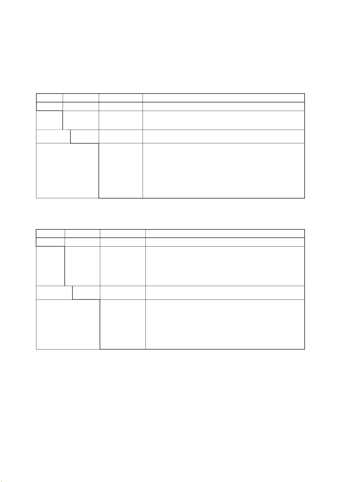
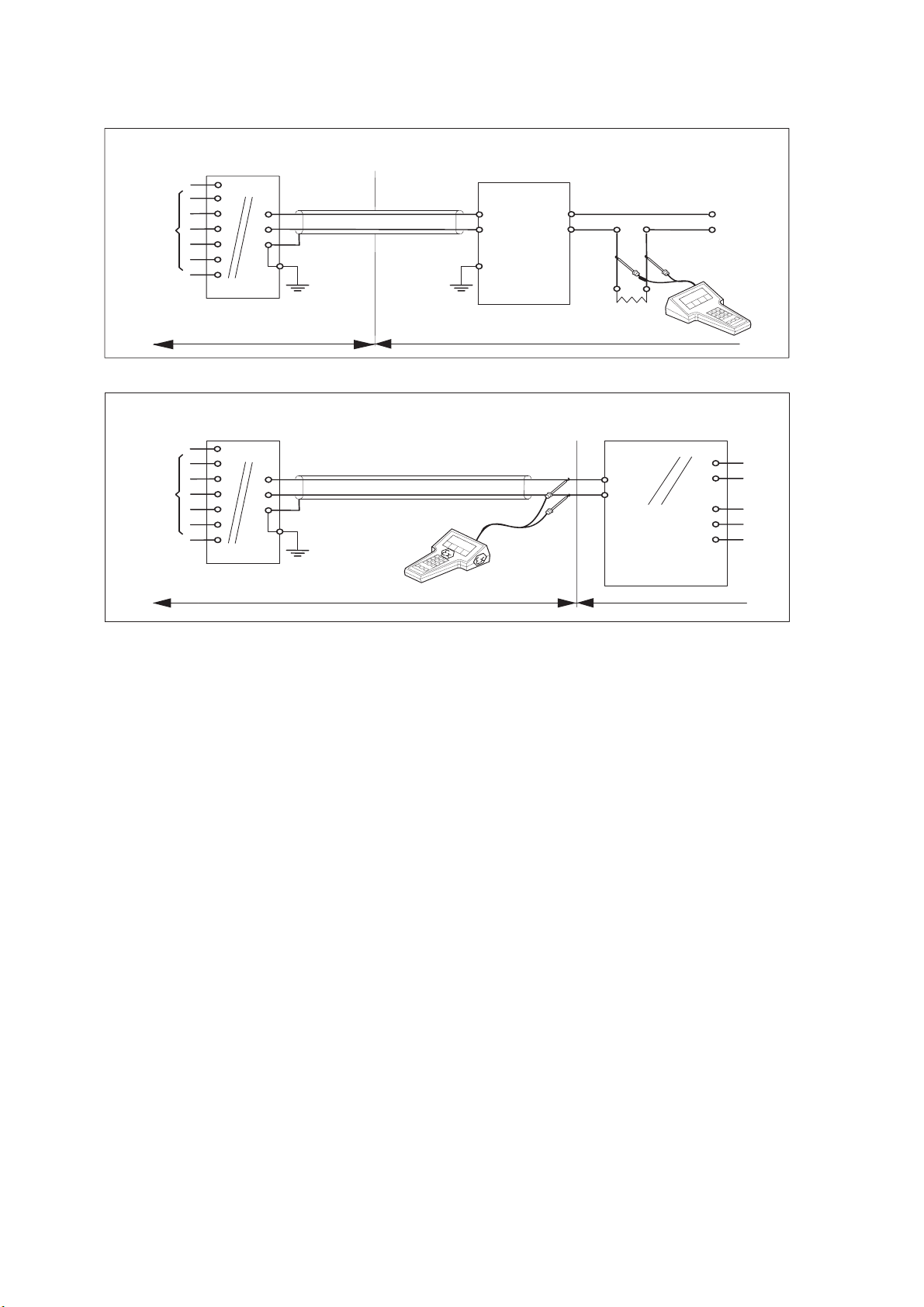
2-6. Control Drawing of DO202S mA HART® Specification (FM Intrinsically safe design)
Intrins i c ally safe design
FM Class I, Div.1, Group ABCD, T4 for ambient temp. < 55°C
T6 for ambient temp. < 40°C
DO202S transmitter
Sensor
terminals 11-18
Max. cablelength: 60 mtr.
Cable dia. : 3…12 mm.
Intrins ic ally safe design
FM Class I, Div.1, Group ABCD, T4 for ambient temp. < 55°C
T6 for ambient temp. < 40°C
DO202S transmitter
+
G
For electrical data:
see text below.
Classified Location
+
G
Functional
earth
FM Approved safety barrier or
power supply
with Rint = 300 :
(HART compatible)
Functional
earth
Unclassified Location
24 volts DC Nominal
Load
Resistance
FM Approved
Power Supply
(HART compatible)
+
Supp ly Voltage.
+
-
Figure 1
Output
Supply
Sensor
terminals 11-18
Max. cablelength: 60 mtr.
Cable dia.: 3…12 mm.
For electrical data:
see text below.
Classified Location
Functional
earth
Ùnclassified Location
Figure 2
・ Electrical data of the DO202S.
- Supply circuit (terminals + and -):
Maximum input voltage Vmax = 31.5 V. Maximum input current Imax = 100 mA.
Maximum input power Pi = 1.2 W.
Effective internal capacitance Ci = 22 nF. Effective internal inductance Li = 35 PH.
- Sensor input circuit (terminals 11 through 18):
Maximum output voltage Vt= 14.4 V. Maximum output current It = 10 mA.
Maximum allowed external capacitance Ca = 643 nF.
Maximum allowed external inductance L
= 340 mH.
a
・ If Hand Held Terminal (HHT) is not connected to the power supply lines of the DO202S
(see figure 1):
Any FM Approved barrier or power supply may be used that meets the following requirements.
V
or V
oc
d 31.5 V; Isc or Itd 100 mA; Cat 22nF + C
t
; Lat 35P H + L
cable
cable
If HHT is connected to the power supply lines of the DO202S (see figure 2):
The Hand Held Terminal must be FM Approved. Refer to the manufacturers control drawing of the
HHT and the barrier/power supply to determine the cable parameters.
(Voc or Vt ) + V
C
t 22nF + C
a
d 31.5 V; (Isc or It ) + I
HHT
cable
+ C
; Lat 35P H + L
HHT
d 100 mA;
HHT
+ L
cable
HHT
When installing this equipment, follow the manufacturer’s installation drawing.
Installation should be in accordance with ANSI/ISA RP 12.06.01 “Installation of Intrinsically Safe
Systems for Hazardous (Classified) Locations” and the National Electrical Code (ANSI/NFPA 70).
Control equipment connected to the barrier/power supply must not use or generate more than 250
Vrms or Vdc.
・ Resistance between Intrinsically Safe Ground and earth ground must be less than1.0 Ohm.
・ In case of using cable glands in Outdoor location, they shall be UV rated or made of metal.
WARNING
- Substitution of components may impair Intrinsic Safety
- To prevent ignition of flammable or combustible atmospheres, disconnect power before servicing or
read, understand and adhere to the manufacturer’s’live maintenance procedures.
Application Doc. No.: IKE030-A10 P.5 to P.6
IM 12J05C01-01E
Page 20
_
_
N
N
2-9 General Specifications
2-7. Control Drawing of DO202S mA HART® Specification (FM Non-incendive design)
onincnendive design
FM Class I, D iv .2, G roup A B C D , T4 for a m b ien t tem p . < 5 5 °C
T6 for ambient temp. < 40°C
DO 202 S tran sitte r
+
G
FM A pproved
power supply
Voc ≤ 31.5 V DC
+
-
Sensor
terminals 11-18
Max. cablelength: 60 mtr.
Cable dia. : 3… 12 mm .
Sensor
terminals 11-18
Max. cablelength: 60 mtr.
Cable dia.: 3… 12 mm
For electrical data:
see text below .
Classified Location Unclassified Location
onincnendive design
FM C lass I, D iv .2, G roup A B C D , T4 for a m b ien t tem p . < 5 5 °C
T6 for ambient temp. < 40°C
DO202S transmitter
Functional
earth
+
G
For electrical data:
see text below.
Classified Location
Functional
earth
Load
Resistance
FM A pproved
power supply
Voc ≤ 31.5 VDC
+
-
Ùnclassified Location
・ Electrical data of the DO202S.
- Supply circuit (terminals + and -):
Maximum input voltage V
= 31.5 V. Maximum input power P
max
= 1.2 W
max
Effective internal capacitance Ci = 22 nF Effective internal inductance Li = 35 μH
・ Sensor input circuit (terminals 11 through 18):
Maximum output voltage V
Maximum allowed external capacitance C
Maximum allowed external inductance L
= 14.4 V. Maximum output current It = 10 mA.
t
= 2.29 μF.
a
= 600 mH.
a
・The Hand Held Terminal must be FM Approved in case it is used in the classified location.
When installing this equipment, follow the manufacturers installation drawing.
Installation shall be in accordance with Article 501.4(B) of the National Electrical Code
(ANSI/NFPA 79).
Nonincendive field wiring may be installed in accordance with Article 501 of the
National Electrical Code
・ Grounding shall be in accordance with Article 250 of the National Electrical code
・ In case of using cable glands in Outdoor location, they shall be UV rated or made of metal.
WARNING
- Substitution of components may impair suitability for Division 2
- Do not remove or replace while circuit is live unless area is know to be non-hazardous
- Explosion Hazard – Do not disconnect equipment unless area is know to be on-hazardous
- Do not reset circuit breaker unless power has been removed from the equipment or the
area is know to be non-hazardous
Application Doc. No.: IKE030-A10 P.7 to P.8
IM 12J05C01-01E
Page 21
General Specifications 2-10
_
_
_
2-8. Control Drawing of DO202S mA HART® Specification (CSA)
Sensor
terminals 1 1-1 8
Sensor
terminals 11-18
Intrin s ic a lly s a fe d e s ign
CSA E x ia C lass I, Div.1, G ro up A B C D, T4 for amb ient tem p . < 5 5 °C
T6 for am b ient tem p. < 4 0° C
DO202S transmitter
+
G
For electrical data:
see text below.
Hazardous area Safe area
Intrinsically safe d esign
CSA Ex ia Class I, Div.1, Group ABCD, T4 for ambient temp. < 55°C
T6 for am b ient tem p . < 4 0° C
DO202S transmitter
Fuctional
earth
Functional
earth
+
G
For electrical data:
see text below.
Hazardous area
Functional
earth
CSA certified safety barrier or
power supply with Rint=300 :
(HA RT c o m p atible )
Suitable values are:
Vmax = 31.5 VoltDC
Imax = 100 mA
Load
Resistance
CSA certified
Power Supply
(HA RT co m p a tib le) )
+
Suit ab le value s a r e :
Vma x = 31 .5 V o ltDC
Imax = 100 mA
Pmax = 1.2 W att
Safe area
24 volts DC N o minal
Supply Voltage.
+
-
Output
Supply
・ Electrical data of the DO202S.
- Supply and output circuit (terminals + and -)
Maximum input voltage V
Maximum input power P
Effective internal capacitance C
= 31.5 V. Maximum input current I
max
= 1.2 W.
max
= 22nF. Effective internal inductance Li = 35 PH.
i
= 100 mA.
max
- Sensor input circuit (terminals 11 through 18):
Maximum output voltage V
Maximum allowed external capacitance C
Maximum allowed external inductance L
= 14.4 V. Maximum output current Isc = 22 mA.
oc
= 643 nF.
a
= 70 mH.
a
・Barriers and power supply should be CSA certified. The specifications must not exceed the
maximum values as shown in the diagram above. Installation should be in accordance
with Canadian Electrical Code, Part I.
Maximum safe area voltage should not exceed 250 V
RMS
.
For Class I, Div. 2, Group ABCD the CSA certified barrier is not required, and the
Sensor input circuit (terminals 11 through 18) is non-incendive having the parameters :
Maximum output voltage V
Maximum allowed external capacitance C
Maximum allowed external inductance L
= 14.4 V. Maximum output current Isc = 22 mA.
oc
= 3.5μF.
a
= 160mH.
a
・ The Hand Held Communicator must be of a CSA certified intrinsically safe type in case it
is used on the intrinsically safe circuit in the hazardous area, or of a CSA certified
non-incendive type in case it is used on the non-incendive circuit in the hazardous area.
IM 12J05C01-01E
Page 22
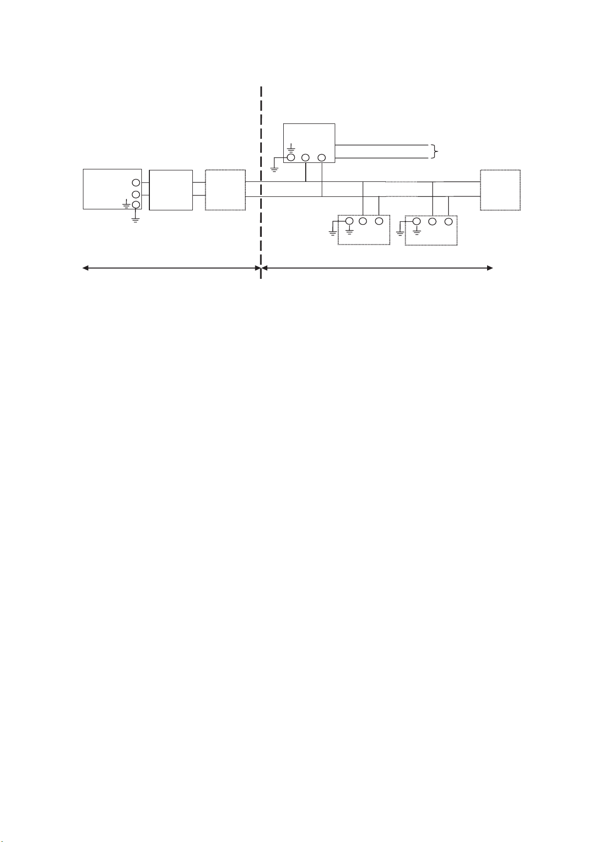
2-9. Control Drawing of DO202S FF/PB Specification (IECEx)
Ex ia IIC
T4 for am bient temp. d 55 qC
Ui = 24 V or U i= 1 7,5 V
Ii = 250 mA Ii = 380 m A
Pi = 1,2 W Pi = 5,32 W
DO202S-F
or DO202S-P
-
+
2-11 General Specifications
Sensor
Connections
Safe area
Apparatus
+
-
Safe area
I.S.
interface
I.S.
certified
Terminator
+
Transm itter
Zone 0 or 1
Hazardous area
-
Transm itter
x Sensor(s) are of a passive type to be regarded as 'simple apparatus'.
x Electrical data of the DO202S-F & DO202S-P:
- Supply and output circuit:
Maximum input voltage Ui = 24 V
Maximum input current Ii = 250 mA
Maximum input power Pi = 1.2 W
Effective internal capacitance Ci = 220 pF;
Effective internal inductance Li = 0 H.
or
FISCO field device
Maximum input voltage Ui = 17.5 V
Maximum input current Ii = 380 mA
Maximum input power Pi = 5.32 W
Effective internal capacitance Ci = 220 pF;
Effective internal inductance Li = 0 H.
I.S.
certified
Terminator
-
+
- Sensor input circuit:
Maximum output voltage Uo = 14.4 V; Maximum output current Io = 22 mA
Maximum allowed external capacitance Co = 643 nF
Maximum allowed external inductance Lo = 70 mH
x Any I.S. interface may be used that meets the following requirements:
Uo d 24 V
Io d 250 mA
Po d 1.2 W
Co t 220 pF + Ccable; Lo t 0 H + Lcable
or
FISCO power supply
Uo d 17.5 V
Io d 380 mA
Po d 5.32 W
Co t 220 pF + Ccable; Lo t 0 H + Lcable
x Electrical data of the DO202S-B & DO202S-D (Type of protection “n”)
- Supply and output circuit:
Maximum input voltage Ui = 32 V
Effective internal capacitance Ci = 220pF; Effective internal inductance Li = 0 H.
- Sensor input circuit:
Maximum output voltage Uo = 14.4 V; Maximum output current Io = 22 mA
Maximum allowed external capacitance Co = 3.5PF
Maximum allowed external inductance Lo = 160 mH
IM 12J05C01-01E
Page 23
General Specifications 2-12
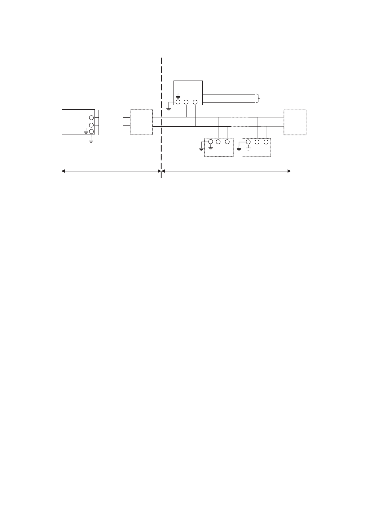
2-10. Control Drawing of DO202S FF/PB Specification (ATEX)
Ex ia IIC
T4 for ambient temp. d 55 qC
Ui = 24 V or Ui = 17,5 V
Ii = 250 mA Ii = 380 mA
Pi = 1,2 W Pi = 5,32 W
DO202S-F
or DO202S-P
-
+
Sensor
Connections
Safe area
Apparatus
+
-
Safe area
I.S.
interface
I.S.
certified
Terminator
+
Transmitter
Zone 0 or 1
Hazardous area
-
+
Transmitter
x Sensor(s) are of a passive type to be regarded as 'simple apparatus'.
x Electrical data of the DO202S-F & DO202S-P:
- Supply and output circuit:
Maximum input voltage Ui = 24 V
Maximum input current Ii = 250 mA
Maximum input power Pi = 1.2 W
Effective internal capacitance Ci = 220 pF;
Effective internal inductance Li = 0 H.
or
FISCO field device
Maximum input voltage Ui = 17.5 V
Maximum input current Ii = 380 mA
Maximum input power Pi = 5.32 W
Effective internal capacitance Ci = 220 pF;
Effective internal inductance Li = 0 H.
I.S.
certified
Terminator
-
- Sensor input circuit:
Maximum output voltage Uo =14.4 V; Maximum output current Io = 22 mA
Maximum allowed external capacitance Co = 643 nF
Maximum allowed external inductance Lo = 70 mH
x Any I.S. interface may be used that meets the following requirements:
Uo d 24 V
Io d 250 mA
Po d 1.2 W
Co t 220 pF + Ccable; Lo t 0 PH + Lcable
or
FISCO power supply
Uo d 17.5 V
Io d 380 mA
Po d 5.32 W
Co t 220 pF + Ccable; Lo t 0 PH + Lcable
x Electrical data of the DO202S-B & DO202S-D (Type of protection “n”)
- Supply and output circuit:
Maximum input voltage Ui = 32V
Effective internal capacitance Ci = 220pF; Effective internal inductance Li = 0 H.
- Sensor input circuit:
Maximum output voltage Uo = 14.4V; Maximum output current Io = 22 mA
Maximum allowed external capacitance Co = 3.5 PF
Maximum allowed external inductance Lo = 160 mH
IM 12J05C01-01E
Page 24

2-13 General Specifications
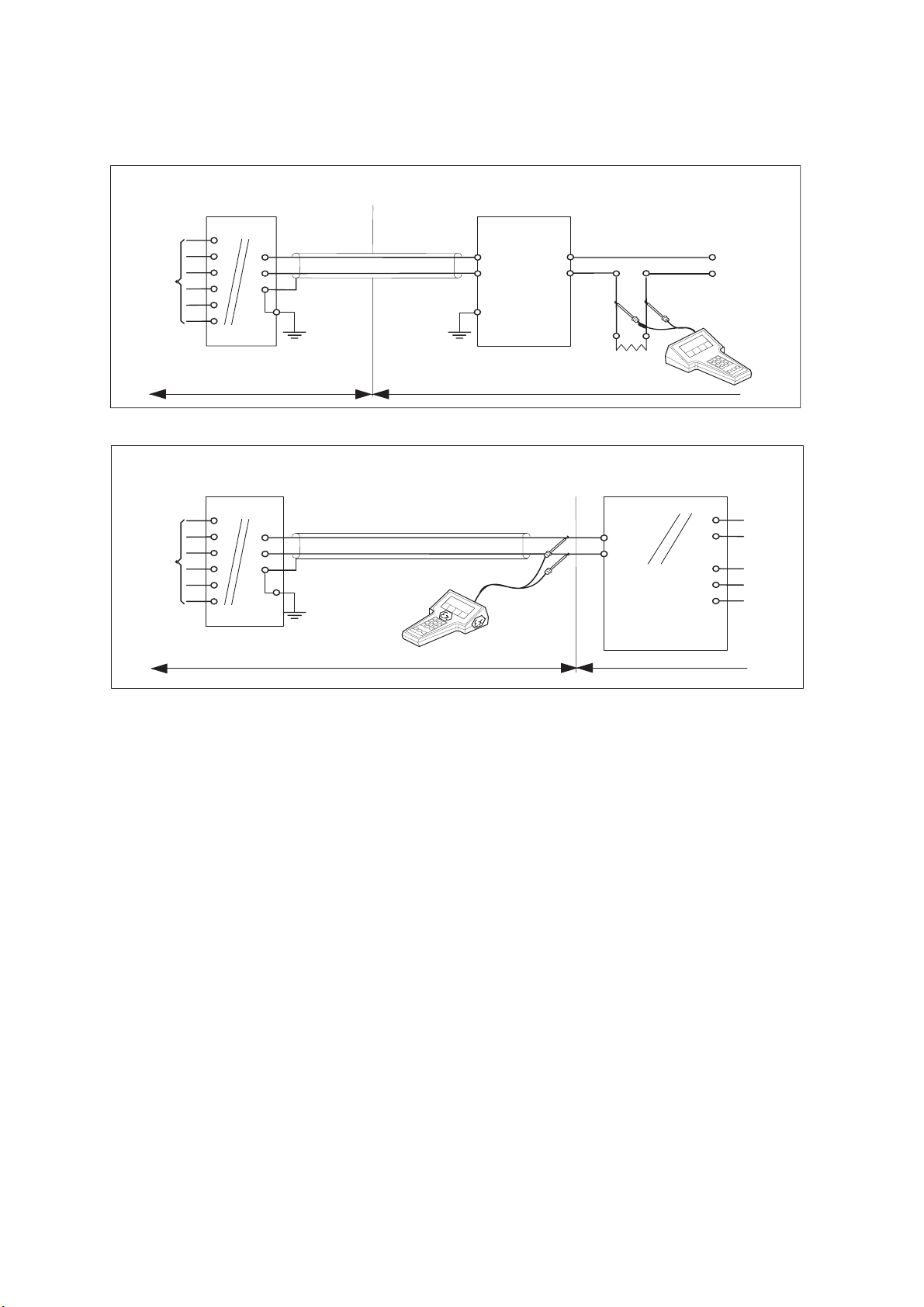
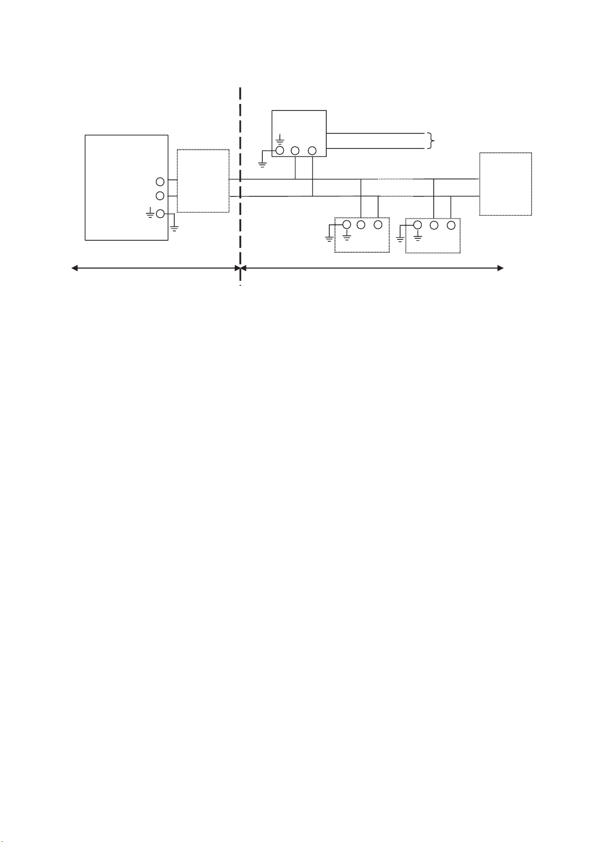
2-11. Control Drawing of DO202S FF/PB Specification (FM Intrinsically safe Entity)
FM Approved
barrier
Voc (Vt) d 24 V
Ioc (It) d 250 mA
Poc (Pt) d 1.2 W
Ca t 220pF+ Ccable
La t 0 H + Lcable
FM Class I, DIV. 1, Group ABCD
T4 for ambient temp. d 55 qC
DO202S-F
or DO202S-P
-
+
+
-
I.S.
certified
Terminator
-
+
Transmitter
Sensor
Connections
Max. cablelength: 60 mtr.
Cable dia. : 3…12 mm.
Sensor
Connections
Terminator
-
+
Transmitter
I.S.
certified
Division 1
Unclassified Location
Classified Location
x Sensor(s) are of a passive type to be regarded as 'simple apparatus', devices which
neither store nor generate voltages over 1.5 V, currents over 0.1 A, power over 25 mW or
energy over 20 PJ, or are FM Approvals entity approved and meet connection
requirements.
x Electrical data of the DO202S-F & DO202S-P:
- Supply circuit:
Maximum input voltage Vmax = 24 V
Maximum input current Imax = 250 mA
Maximum input power Pi = 1.2 W
Effective internal capacitance Ci = 220 pF;
Effective internal inductance Li = 0 PH.
- Sensor input circuit:
Maximum output voltage Vt = 14.4 V; Maximum output current It = 10 mA
Maximum allowed external capacitance Ca = 643 nF
Maximum allowed external inductance La = 340 mH
x Any FM Approved barrier may be used that meets the following requirements:
Voc or Vt d 24 V
Ioc or It d 250 mA
Poc or Pt d 1.2 W
Ca t 220 pF + Ccable; La t 0 H + Lcable
When installing this equipment, follow the manufacturer’s installation drawing.
Installation should be in accordance with ANSI/ISA RP 12.06.01 “Installation of
Intrinsically Safe Systems for Hazardous (Classified) Locations” and the National
Electrical Code (ANSI/NFPA 70).
Associated apparatus connected to the barrier must not use or generate more than
250 Vrms or Vdc.
x Resistance between Intrinsically Safe Ground and earth ground must be less than 1.0
Ohm.
x In case of using cable glands in Outdoor location, they shall be UV rated or made of metal.
WARNING
- Substitution of components may impair Intrinsic Safety
- To prevent ignition of flammable or combustible atmospheres, disconnect power
before servicing or read, understand and adhere to the manufacturer’s live
maintenance procedures.
IM 12J05C01-01E
Page 25

General Specifications 2-14
x The cable used to interconnect the devices needs to comply with the following
parameters:
Loop resistance R’: 15 … 150 /km; Inductance per unit length L’: 0,4 … 1 mH/km
Capacitance per unit length C’: 80 … 200 nF/km
(C’ = C’ line/line + 0,5 C’ line/screen if both line are floating)
(C’ = C’ line/line + C’ line/screen if the screen is connected to one line)
Length of spur cable: max. 30 m
Length of trunk cable: max. 1 km
Length of splice : max. 1 m
WARNING
- Substitution of components may impair Intrinsic Safety
- To prevent ignition of flammable or combustible atmospheres, disconnect power
before servicing or read, understand and adhere to the manufacturer’s live
maintenance procedures.
Application Doc. No.: IKE031-A10 P.5 to P.6
IM 12J05C01-01E
Page 26
2-15 General Specifications
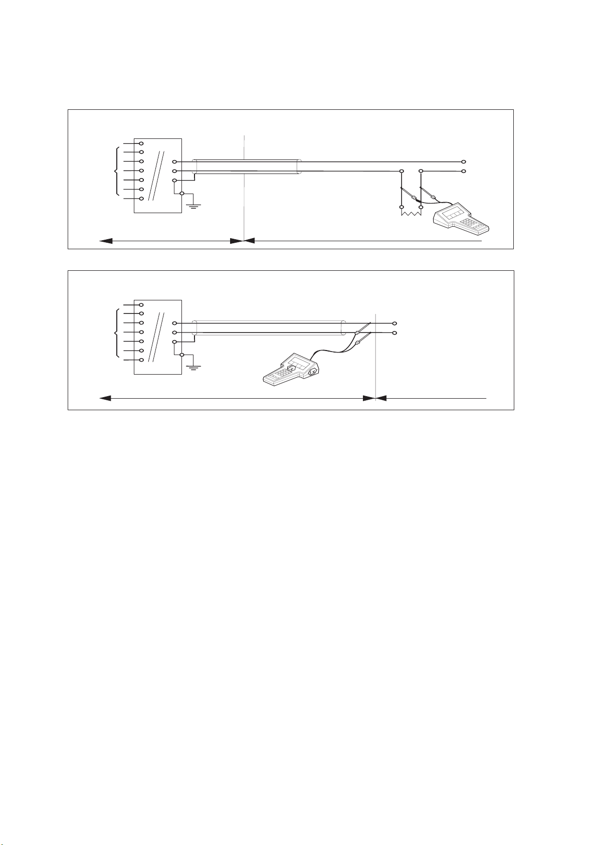
2-12. Control Drawing of DO202S FF/PB Specification (FM Intrinsically safe FISCO)
FM Approved
FISCO barrier
Voc (Vt) d17,5 V
Ioc (It) d380 mA
Poc (Pt) d5,32 W
FM Class I, DIV. 1, Group ABCD
T4 for ambient temp. d 55 qC
DO202S-F
or DO202S-P
-
+
FM Approved
Terminator
-
R = 90..100
C = 0..2,2 F
-
+
Transmitter
+
Sensor
Connections
Max. cablelength: 60 mtr.
Cable dia. : 3…12 mm.
Sensor
Connections
-
+
Transmitter
FM Approved
Terminator
R = 90..100
C = 0..2,2 F
Division 1
Unclassified Location
Classified Location
x Sensor(s) are of a passive type to be regarded as 'simple apparatus', devices which
neither store nor generate voltages over 1.5 V, currents over 0.1 A, power over 25 mW or
energy over 20 PJ, or are FM Approvals entity approved and meet connection
requirements.
x Electrical data of the DO202S-F & DO202S-P:
- Supply circuit: Vmax = 17.5 V; Imax = 380 mA; Pi = 5.32 W; Ci = 220 pF; Li = 0 H.
- Sensor input circuit: Vt = 14.4 V; It = 10 mA; Ca = 643 nF; La = 340 mH
x Any FM Approved FISCO barrier may be used that meets the following requirements:
Voc or Vt d 17,5 V; Ioc or It d 380 mA; Poc or Pt d 5,32 W
When installing this equipment, follow the manufacturer’s installation drawing.
Installation should be in accordance with ANSI/ISA RP 12.06.01 “Installation of
Intrinsically Safe Systems for Hazardous (Classified) Locations” and the National
Electrical Code (ANSI/NFPA 70).
Associated apparatus connected to the FISCO barrier must not use or generate more
than 250 Vrms or Vdc.
x Resistance between FISCO Intrinsically Safe Ground and earth ground must be less than
1.0 Ohm.
x In case of using cable glands in Outdoor location, they shall be UV rated or made of metal.
x The FISCO concept allows the interconnection of several I.S. apparatus not specifically
examined in such combination. The criterion for such interconnection is that the voltage
(Vmax), the current (Imax) and the power (Pi) which I.S. apparatus can receive and remain
intrinsically safe, considering faults, must be equal to or greater that the voltage (Voc, Vt),
the current (Ioc, It) and the power (Poc, Pt) which can be provided by the FM approved
FISCO barrier. In addition, the maximum unprotected residual capacitance (Ci) and
inductance (Li) of each apparatus (other than the terminator) connected to the Fieldbus
must be less than or equal to 5nF and 10 H respectively.
IM 12J05C01-01E
Page 27

General Specifications 2-16
x In each I.S. Fieldbus segment only one active source, normally the FM Approved FISCO
barrier, is allowed to provide the necessary power for the Fieldbus system. All other
equipment connected to the bus cable has to be passive (not providing energy to the
system), except to a leakage current of 50A for each connected device. Separately
powered equipment needs a galvanic isolation to insure that the I.S. Fieldbus circuit
remains passive.
x The cable used to interconnect the devices needs to comply with the following
parameters:
Loop resistance R’: 15 … 150 /km; Inductance per unit length L’: 0,4 … 1 mH/km
Capacitance per unit length C’: 80 … 200 nF/km
(C’ = C’ line/line + 0,5 C’ line/screen if both line are floating)
(C’ = C’ line/line + C’ line/screen if the screen is connected to one line)
Length of spur cable: max. 30 m
Length of trunk cable: max. 1 km
Length of splice : max. 1 m
WARNING
- Substitution of components may impair Intrinsic Safety
- To prevent ignition of flammable or combustible atmospheres, disconnect power
before servicing or read, understand and adhere to the manufacturer’s live
maintenance procedures.
Application Doc. No.: IKE031-A10 P.7 to P.8
IM 12J05C01-01E
Page 28

p
2-17 General Specifications
2-13. Control Drawing of DO202S FF/PB Specification (FM Non-incendive Entity)
FM Class I, DIV. 2, Group ABCD
FM Approved
Power Supply
Voc d 32 VDC
T4 for ambient temp. d 55 qC
T6 for ambient tem
DO202S-B
or DO202S-D
+
FM Approved
Terminator
+
-
R = 90..100
C = 0..2,2 F
-
. d 40 qC
-
+
Transmitter
Sensor
Connections
Max. cablelength: 60 mtr.
Cable dia.: 3…12 mm.
Sensor
Connections
-
+
Transmitter
FM Approved
Terminator
R = 90..100
C = 0..2,2 F
Division 2
Unclassified Location
x
Sensor(s) are of a passive type to be regarded as 'simple apparatus', devices which
Classified Location
neither store nor generate voltages over 1.5 V, currents over 0.1 A, power over 25 mW or
energy over 20 PJ, or are FM Approvals entity approved and meet connection
requirements.
x Electrical data of the DO202S-B & DO202S-D:
- Supply circuit: Vmax = 32 V; Pi = 1.2 W; Ci = 220 pF; Li = 0 H
- Sensor input circuit: Vt = 14.4 V; It = 10 mA; Ca = 2.29 PF; La = 600 mH
When installing this equipment, follow the manufacturers installation drawing.
Installation shall be in accordance with Article 501.4(B) of the National Electrical Code
(ANSI/NFPA 79). Nonincendive field wiring may be installed in accordance with Article
501.4(B)(3)
x Grounding shall be in accordance with Article 250 of the National Electrical code.
x In case of using cable glands in Outdoor location, they shall be UV rated or made of metal.
WARNING
- Substitution of components may impair suitability for Division 2.
- Do not remove or replace while circuit is live unless area is know to be non-hazardous
- Explosion Hazard – Do not disconnect equipment unless area is know to be
non-hazardous
- Do not reset circuit breaker unless power has been removed from the equipment or the
area is know to be non-hazardous
Application Doc. No.: IKE031-A10 P.9
IM 12J05C01-01E
Page 29

General Specifications 2-18
p
2-14. Control Drawing of DO202S FF/PB Specification (FM Non-incendive FNICO)
FM Class I, DIV. 2, Group ABCD
FM Approved
Power Supply
Voc d 32 VDC
+
T4 for ambient temp. d 55 q C
T6 for ambient tem
DO202S-B
or DO202S-D
+
FM Approved
Terminator
R = 90..100
-
C = 0..2,2 F
-
. d 40 qC
-
+
Transmitter
Sensor
Connections
Max. cablelength: 60 mtr.
Cable dia.: 3…12 mm.
Sensor
Connections
-
+
Transmitter
FM Approved
Terminator
R = 90..100
C = 0..2,2 F
Division 2
Unclassified Location
x
Sensor(s) are of a passive type to be regarded as 'simple apparatus', devices which
Classified Location
neither store nor generate voltages over 1.5 V, currents over 0.1 A, power over 25 mW or
energy over 20 PJ, or are FM Approvals entity approved and meet connection
requirements.
x Electrical data of the DO202S-B & DO202S-D:
- Supply circuit: Vmax = 32 V; Pi = 5.32 W; Ci = 220 pF; Li = 0 H
- Sensor input circuit: Vt = 14.4 V; It = 10 mA; Ca = 2.29 PF; La = 600 mH
When installing this equipment, follow the manufacturers installation drawing.
Installation shall be in accordance with Article 501.4(B) of the National Electrical
Code (ANSI/NFPA 79).
Non-incendive field wiring may be installed in accordance with Article 501.4(B)(3)
x Grounding shall be in accordance with Article 250 of the National Electrical code.
x In case of using cable glands in Outdoor location, they shall be UV rated or made of metal.
WARNING
- Substitution of components may impair suitability for Division 2.
- Do not remove or replace while circuit is live unless area is know to be non-hazardous
- Explosion Hazard – Do not disconnect equipment unless area is know to be
non-hazardous
- Do not reset circuit breaker unless power has been removed from the equipment or the
area is know to be non-hazardous
Application Doc. No.: IKE031-A10 P.10
IM 12J05C01-01E
Page 30

2-15. Control Drawing of DO202S FF/PB Specification (CSA)
CSA Ex ia Class I, DIV. 1, Group ABCD
T4 for ambient temp. d 55 qC
Ui = 24 V or Ui = 17,5 V
Ii = 250 mA Ii = 380 mA
Pi = 1,2 W Pi = 5,32 W
DO202S-F
or DO202S-P
-
+
2-19 General Specifications
Sensor
Connections
Safe area
Apparatus
+
-
Safe area
I.S.
interface
I.S.
certified
Terminator
+
Transmitter
Zone 0 or 1
-
Transmitter
-
+
I.S.
certified
Terminator
Hazardous area
x Sensor(s) are a thermocouple, RTD's, passive resistive switch devices, or is CSA entity
approved and meet connection requirements.
x Electrical data of the DO202S-F & DO202S-P:
- Supply and output circuit:
Maximum input voltage Ui = 24 V
Maximum input current Ii = 250 mA
Maximum input power Pi = 1.2 W
Effective internal capacitance Ci = 220 pF;
Effective internal inductance Li = 0 H.
or
FISCO field device
Maximum input voltage Ui = 17.5 V
Maximum input current Ii = 380 mA
Maximum input power Pi = 5.32 W
Effective internal capacitance Ci = 220 pF;
Effective internal inductance Li = 0 H.
- Sensor input circuit:
Maximum output voltage Uo = 14.4 V; Maximum output current Io = 22 mA
Maximum allowed external capacitance Co = 643 nF
Maximum allowed external inductance Lo = 70 mH
x Any CSA approved I.S. interface may be used that meets the following requirements:
Uo d 24 V
Io d 250 mA
Po d 1.2 W
Co t 220 pF + Ccable; Lo t 0 H + Lcable
or
FISCO power supply
Uo d 17.5 V
Io d 380 mA
Po d 5.32 W
Co t 220 pF + Ccable; Lo t 0 H + Lcable
Installation should be in accordance with Canadian Electrical Code, Part I or CEC, Part I.
Maximum safe area voltage should not exceed 250 Vrms.
x Electrical data of the DO202S-B & DO202S-D (non-incendive):
For Class I, Div.2, Group ABCD the CSA approved I.S. interface is not required, and the
sensor input circuit is non-incendive having the parameters:
Maximum output voltage Uo = 14.4 V; Maximum output current Io = 22 mA
Maximum allowed external capacitance Co = 3.5 PF
Maximum allowed external inductance Lo = 160 mH
IM 12J05C01-01E
Page 31

General Specifications 2-20
IM 12J05C01-01E
Page 32

3. INSTALLATION AND WIRING
A
3-1. Installation and dimensions
3-1 Installation and Wiring
3-1-1. Installation site
The EXA transmitter is weatherproof and can be installed
inside or outside. It should, however, be installed as
The ambient temperature and humidity of the installation environment must be within the limits of the
instrument specifications. (See chapter 2).
close as possible to the sensor to avoid long cable runs
between sensor and transmitter. In any case, the cable
length should not exceed 30 mtr (100 feet).
Select an installation site where:
When the instrument with Suffix Code "-B,-N,-D" is
used, take measures so that the display window is
not exposed to direct sunlight.
• Mechanical vibrations and shocks are negligible
• No relay/power switches or RF transmitters are in
the direct environment
• Access is possible to the cable glands (figure 3-1)
3-1-2. Mounting methods
Refer to figures 3-2 and 3-3. Note that the EXA
transmitter
• Panel mounting using optinal bracket, refer to Fig.
• The transmitter is not mounted in direct sunlight or
severe weather conditions
• Panel mounting using two (2) self-tapping screws,
• Maintenance procedures are possible (avoiding
corrosive environments)
• Surface mounting on a plate
• Wall mounting on a bracket
• Pipe mounting using a bracket on a horizontal or
(7.95)
202
(6.4) (6.1)
180
(7)
162
130
(5.1)
50
(2)
155
30
(1.2)
has universal mounting capabilities:
3-2a.
refer to Fig. 3-2b.
(using bolts from the back)
(for example, on a solid wall)
vertical pipe (Nominal pipe diameter 50 A)
Panel thickness
1 to 10
(0.04 to 0.39)
(1.2)
30
60
(2.36)
Unit: mm (inch)
Panel mounting
bracket
Hood (Option)
□
115
Grounding terminal
(M4 screw)
9
(0.35)
42
(1.65)
34
(1.3)
56±0.2
(2.20)
Option code : / H
(2.7)
68
Sensor cable inlet
cable gland (Pg13.5)
M6 screw (32 )
Transmission signal cable inlet
Cable gland : Pg13.5
dapter
G1/2 screw (/AFTG)
1/2 NPT screw (/ANSI)
Figure 3-1. Housing dimensions and layout of glands
77
(3)
(4.5)
(1.26) depth
1.eps
49
(1.93)
2.eps
Approx.
55
(2.2)
156
(6.14)
+1.1
0
185
205
80
3.9
(0.15)
38
(1.5)
(3.15)
PANEL CUTOUT
+1.1
173
0
138
(5.43)
(6.81)
121
(4.76)
Figure 3-2a. Panel mounting diagram
(7.28)
(8.07)
5.eps
IM 12J05C01-01E
Page 33

Installation and Wiring 3-2
Unit: mm (inch)
+1
0
+1
0
18.5
SPACING PANEL CUTOUT
(0.72)
PANEL CUTOUT
Fig. 3-2b. Panel mounting using two (2) self-tapping screws
56
(2.20)
2-Ø6.5
(0.26)
200
(7.87)
4-Ø10
(0.4)
(3)
77
115
70
(2.75)
(4.5)
Figure 3-3. Wall and pipe mounting diagram
3.5
(0.14)
Pipe mounting
(Vertical)
Pipe mounting
(Horizontal)
Nominal 50 A (O.D. Ø60.5 mm)
(2 inch pipe)
4.eps
Figure 3-4. Internal view of EXA wiring compartment
IM 12J05C01-01E
Page 34

3-3 Installation and Wiring
3-2. Wiring of power supply
3-2-1. General precautions
mA
Do not activate the power supply yet. First make
sure that the DC-power supply is according to the
specifications given.
WARNINGWARNING
DO NOT USE ALTERNATING CURRENT OR MAINS
POWER SUPPLY! !
The cable leading to the distributor (power supply) or
safety barrier transports power to and output signal
from the transmitter. Use a two conductor shielded
cable with a size of at least 1.25 mm
diameter of 6 to 12 mm. The cable gland supplied
with the instrument accepts these diameters. The
maximum length of the cable is 2000 metre, or 1500
metres when using the communications. This ensures
the minimum operating voltage for the instrument.
Grounding:
• If the transmitter is mounted on a grounded
surface (e.g. a metal frame fixed in the soil) the
shield of the 2-wire cable may NOT be connected
to ground at the distributor.
• If the transmitter is mounted on a non-conducting
surface (e.g. a brick wall) it is recommended
to ground the shield of the 2-wire cable at the
distributor end.
mA
3-2-2. Connection of the power supply
The terminal strip is accessed as was described in
section 3-2-1. Use the left-hand gland to insert the
supply/output cable to the transmitter. Connect the
supply to the terminals marked +, - and G as is indicated in figures 3-7.
3-2-3. Switching the instrument on
After all connections are made and checked, the
power can be switched on from the distributor.
Observe the correct activation of the instrument at
the display. If for any reason the display does not
indicate a value, consult the trouble shooting section.
mA
3-2-4. Preparation
Refer to figure 3-4. The power/output connections
and the sensor connections should be made. Refer
to figure 3-7. The terminals are of a plug in style for
ease of mounting.
To open the EXA 202 for wiring:
1. Loosen the four frontplate screws and remove
the cover.
2. The terminal strip is now visible.
3. Connect the power supply. Use the gland on the
left for this cable.
4. Connect the sensor input, using the gland on
the right (see fig. 3-5). Switch on the power.
2
and an outside
Commission the instrument as required or use
the default settings.
5. Replace the cover and secure frontplate with the
four screws.
6. Connect the grounding terminals to protective
earth.
7.
The optional hose connection is used to guide the
cables coming from an immersion fitting through a
protective plastic tubing to the transmitter.
3-2-5. Cables, terminals and glands
The DO202 is equipped with terminals suitable for
the connection of finished cables in the size range:
0.13 to 2.5 mm (26 to 14 AWG). The glands will
Sensor
cable gland
Power/Output
cable gland
Grounding terminal
Figure 3-5. Glands to be used for cabling
form a tight seal on cables with an outside diameter
in the range of 6 to 12 mm (0.24 to 0.47 inches).
3-3. Wiring of sensors
3-3-1. Wiring the standard galvanic sensor
The sensor cable has markers on the individual wires.
These markings refer to the markers on the terminals.
The temperature sensor has two wires with the
markings T1, T2 and/or 11, 12 and must be connected to terminal 11 and 12.
The measuring electrode: the cathode is marked with
IE and/or 13 and must be connected to terminal 13.
The reference electrode: the anode is marked with
RE and/or 15 and must be connected to terminal 15.
The liquid earth (solution ground) is marked with 16
and must be connected to terminal 16.
The overall shield of the cable is marked with 14
and must be connected to terminal 14.
Place the jumper in the GALVANIC position.
IM 12J05C01-01E
Page 35

Installation and Wiring 3-4
3-3-2. Wiring other galvanic sensors
Consult the users manual for the color identification
of the sensor cable.
- The temperature sensor has two wires and must
be connected to the terminal 11 and 12.
- The measuring electrode: the cathode must be
connected to terminal 13.
- The reference electrode: the anode must be
connected to terminal 15.
- The overall shield of the cable must be connected
to terminal 14 if there is one available.
- Place the jumper in the GALVANIC position.
3-3-3. Wiring polarographic sensors
Consult the owners manual for the color identification of the sensor cable.
- The temperature sensor has two wires and must
be connected to the terminal 11 and 12.
- The measuring electrode: the cathode must be
connected to terminal 17.
- The reference electrode: the anode must be
connected to terminal 18.
- The overall shield of the cable must be connected
to terminal 14 if there is one available.
- Place the jumper in the POLAROGRAPHIC position.
3-3-4. Wiring sensors with Vp connector
Consult the owners manual for the color identification of the sensor cable
- The temperature sensor has two wires and must
be connected to terminal 11 and 12
- Polarographic : the measuring electrode
(cathode) must be connected to terminal 17
- Polarographic : the reference electrode (anode)
must be connected to terminal 18
- Galvanic : the measuring electrode (cathode)
must be connected to terminal 13
- Galvanic : the reference electrode (anode) must
be connected to terminal 15
- The overall shield of the cable must be connected
to 14
- Place the jumper in the Polarographic or Galvanic
position
A-17 pol. 13 galv.
B-18 pol. 15 galv.
C
D
E-11
F-12
S-14
temp
Figure 3-7. Terminal indentification labels
3-3-5. Sensor cable connections using junction
box (BA10) and extension cable (WF10)
Where a convenient installation is not possible using
the standard cables between sensors and transmitter, a junction box and extension cable may be
used. The Yokogawa BA10 junction box and the
WF10 extension cable should be used. These items
are manufactured to a very high standard and are
necessary to ensure that the specifications of the
system are not compromised. The total cable length
17
1314141615
12
11
11 Re d
12 Blue
15
14 16
14
17
13
12
11
15 Core 16 Screen
White Co-axial cable
14 Overall Screen
13 Core 17 Screen
Brown Co-axial Cable
WF10 Cable
Figure 3-6. Connections DO
should not exceed 30 metres (including DO sensor
cable).
TRANSMITTER / CONVERTER
11
12
17
13
15
16
14
Brown
Screen
Red
C
E
Overall
shield
A
D
Blue
B
White
Figure 3-8. Connection of WF10 extension cable and BA10/BP10 junction box
IM 12J05C01-01E
Page 36

3-5 Installation and Wiring
Extension cable may be purchased in bulk quantities, cut to length. Then it is necessary to terminate
the cable as shown below.
Termination procedure for WF10 cable.
1. Slide 3 cm of heat shrink tube (9 x 1.5) over the
cable end to be terminated.
Strip 9 cm of the outer (black) insulating material,
2.
taking care not to cut or damage internal cores.
Figure 3-9a.
3 cm
heat shrink
9 cm
remove insulation
3. Remove loose copper screening, and cut off the
cotton packing threads as short as possible.
4. Strip insulation from the last 3 cm of the brown,
and the white coaxial cores.
3-3-6. Additional precautions for installations in
hazardous areas
Make sure that the total of capacitance and inductances connected to the input terminals of the EXA
DO202S do not exceed the limits given in the certificate.
This sets a limit to the cable and extensions used.
– The intrinsic safe version of the DO202S
instrument can be mounted in Zone 1 (DO202S-B,
-N, -D).
– The sensors can be installed in Zone 0 or Zone 1
if a safety barrier according to the limits given in
the system certificate is used.
– Ensure that the total of capacitance and
inductances connected to the terminals of the
EXA DO202S do not exceed the limits given in the
certificate of the safety barrier or distributor.
– The cable used should preferably have a BLUE
colour or marking on the outside.
– Installation for (sensors in Zone 0 or 1):
Generally, the distributor with input/output isolation
has no external earth connection. If there is
an earth connection on the distributor and the
external connection of the transmitter is connected
to “protective” earth, the shield of the 2-wire cable
may NOT be connected to “protective” earth at the
distributor too.
3 cm
cotton threads
Figure 3-9b.
5. Extract the coaxial cores from the braid, and trim
off the black (low-noise) screening material as
short as possible.
Insulate the overall screen and drain wire (14) and
6.
the 2 coaxial screens with suitable plastic tubing.
7. Strip and terminate all ends with suitable (crimp)
terminals and identify with numbers as shown.
Red
11
Blue
12
Black
14
White
15
16
Brown
13
3-3-7. Installation in:
Hazardous Area-Non-Incendive
The EXA DO202S-B, -N, -D may be installed in a
Category 3, Zone 2, Div.2 area without the use of
safety barriers. Maximum permissible supply voltage
31.5V.
Figure 3-9c.
8. Finally shrink the overall heat shrink tube into
position.
IM 12J05C01-01E
Page 37

IM 12J05C01-01E
Page 38

4. OPERATION; DISPLAY FUNCTIONS AND SETTING
Operation: Display Functions and Settings 4-1
4-1. Operator interface
This section provides a survey of the operation of
the EXA operator interface. The basic procedures for
obtaining access to the three levels of operation are
described briefly. For a step-by-step guide to data
entry, refer to the relevant section of this user’s manual. Figure 4-1 shows the EXA operator interface.
LEVEL 1: Maintenance
These functions are accessible by pushbutton
through a flexible front cover window. The functions
make up the normal day-to-day operations that an
operator may be required to complete. Adjustment
of the display and routine calibration are among the
features accessible in this way. (See table 4-1).
Table 4-1. Operations overview
Routine Function Chapter
Maintenance
Commissioning
mA
CALIB
DISP
M.TEMP
M.PRESS
OUTP
HOLD
AIR.CAL
H2O.CAL
SENS
ZERO
LEVEL 2: Commissioning
A second menu is exposed when the EXA front
cover is removed and the display board is revealed.
Users gain access to this menu by pressing the button marked * in the lower right of the display board.
This menu gives access to the service menu.
(See table 4-1).
LEVEL 3: Service
For more advanced configuration selections, press
the button marked *. Now push the “YES” button.
Selecting and entering “Service Code” numbers in
the commissioning menu provide access to the
more advanced functions. An explanation of the
Service Codes is listed in chapter 5 and an overview table is shown in chapter 11.
Calibration in air (preferred method)
Calibration in aerated water
Manual sensitivity calibration
Manual zero calibration
Read auxiliary data or set message display
Adjust manual temperature
Adjust manual pressure
Adjust the output range
Activate the hold function
6
6
6
6
4
5
5
5
5
Service
(access to coded entries from
the commissioning level)
SERV Fine tune the specialized functions of the transmitter 5
Note: All three levels may be separately protected by a password. See Service Code 52 in chapter 5
Service Code table for details on setting passwords.
IM 12J05C01-01E
Page 39

4-2 Operation: Display Functions and Settings
Main display Menu pointer flags
Message display
YES NO
Key prompt flags
Selection keys
YES : Accept setting
NO : Change setting
Adjustment keys
> : Choose digit to
adjust
^ : Adjust digit
ENT : Confirm change
Figure 4-1. DO202 operator interface
NO MODEYES
4-2. Explanation of operating keys
Fail flag
FAI LTEMP.MAN
ENT
MODE
Commissioning
function menu
Commissioning mode
access key
Measure/Maintenance
mode key
ENT
ppm
ppb
%sat
CAL
DISPLAY
HOLD
OUTPUT
SET HOLD
SERVICE
Broken line indicates area that can be
seen through front cover
cover removed or opened. Once this button
has been used to initiate the commissioning
MODE key
This key toggles between the measuring and
menu, follow the prompts and use the other
keys as described above.
maintenance modes. Press once to obtain
access to the maintenance function menu.
4-3. Passcode protection
CALIB
DISP
Press again to return to the measuring mode.
In Service Code 52, passcode protection can be set
for each one of the three operating levels, individually. This procedure should be completed after the
YES/NO keys
These are used to select choices from the menu.
YES is used to accept a menu selection.
initial commissioning (setup) of the instrument. The
passcodes should then be recorded safely for future
reference.
NO is used to reject a selection, or to move
ahead to the next option.
When passcodes have been set, the following additional steps are introduced to the configuration and
DATA ENTRY keys (
)
programming operations:
Is used as a “cursor” key. Each press
on this key moves the cursor or flashing
digit one place to the right. This is used
to select the digit to be changed when
entering numerical data.
Maintenance
Press MODE key. The display shows 000 and *PASS*
Enter a 3-digit passcode as set in Service Code 52
to obtain access to the Maintenance Mode.
Is used to change the value of a selected
digit. Each press on this key increases the
value by one unit. The value can not be
decreased, so in order to obtain a lower
value, increase past nine to zero, then
Commissioning
Press key. The display shows 000 and *PASS*
Enter a 3-digit passcode as set in Service Code 52
to obtain access to the Commissioning Mode.
increase to the required number.
When the required value has been set
using the
and
keys, press to
confirm the data entry. Please note that
the EXA does not register any change of
data until the ENT key is pressed.
Service
From the Commissioning menu, select *Service by
pressing YES key. The display shows 000 and *PASS*
Enter a 3-digit passcode as set in Service Code 52
to obtain access to the Service Mode.
This is the commissioning mode key. It is
key
used to obtain access to the commissioning menu. This can only be done with the
Note: See Service Code 52 for the setting of
passcodes.
IM 12J05C01-01E
Page 40

Operation: Display Functions and Settings 4-3
4-4. Display examples
The following pages show the sequence of button
presses and screens displayed when working in
some standard configurations. More or less options
will be made available by the configuration of some
4-5. Display function (default)
MODE
FAILTEMP.MAN
ppm
ppb
%sat
ENT
ENT
CAL
DISPLAY
HOLD
OUTPUT
SET HOLD
SERVICE
YES NO
NO MODEYES
service codes, or by choices made in the commissioning menu.
The following deviations are possible:
Item marked is omitted when switched off in
*
commissioning mode.
Cell current
YES
NO
Sensitivity
(slope)
YES
NO
Zero current
YES
DISPLAY
NO
DISPLAY
NO
DISPLAY
NO
MODE
YES NO
NO
YES NO
NO
YES
NO
NO
Software release
PPM
PPB
%SAT
CAL
DISPLAY
HOLD
number
YES
NO
DISPLAY
NO
Process
YES
CAL (SEE
CALIBRATION
CHAPTER 6)
temperature
YES
YES
NO
NO
NO
DISPLAY
Output
YES
DISPLAY
mA
YES
NO
DISPLAY
NO
% Saturation
YES
SEE MANUAL
NO
TEMPERATURE
(CHAPTER 5)
YES
NO
DISPLAY
NO
IM 12J05C01-01E
YES
NO
Unit
NO
YES
SEE MANUAL
PRESSURE
(CHAPTER 5)
YES
NO
DISPLAY
NO
Process
pressure
YES
DISPLAY
NO
Page 41

5. PARAMETER SETTING
5-1 Parameter Setting
5-1. Maintenance mode
Standard operation of the EXA instrument involves
use of the Maintenance (or operating) mode to set
up some of the parameters.
Access to the Maintenance mode is available
via the six keys that can be pressed through
the flexible window in the instrument cover.
Press the MODE key once to enter this dialog
mode.
Note: At this stage the user will be prompted for
pass code where this has been previously set
up in service code 52 in chapter 5.
5-1-1. Manual activation of hold
mA
Calibration Air See “calibration” section 6.
H
2O See “calibration” section 6.
Sensitivity See “calibration” section 6.
Zero See “calibration” section 6.
mA
Hold Manually switch on/off
“hold” (when enabled in
Commissioning menu).
See adjustment procedure
5-2-2.
Display See “operation” section 4.
Manual temperature See “manual temperature
adjustment” section 5-1-2.
Manual pressure See “manual pressure
adjustment” section 5-1-3.
YES NO
NO MODEYES
MODE
YES NO
NO
NO
FAILTEMP.MAN
ENT
ENT
CALIBRATE
MODE
ppm
ppb
%sat
CAL
DISPLAY
HOLD
OUTPUT
SET HOLD
SERVICE
NO
NO
HOLD
HOLD
NO
YES N O
YES
YES
YES NO YES NO
YES
MEASURE
IM 12J05C01-01E
Page 42

Parameter Setting 5-2
%SAT
PPB
CAL
DISPLAY
PPM
HOLD
MODE
NO 2x
YES
YES NO
TEMP.MAN
ENT
>
Set using >, ,ENT keys.
Manual temperature
5-1-2. Manual temperature adjustment
5-1-3. Manual pressure adjustment
PPM
PPB
%SAT
CAL
DISPLAY
HOLD
MODE
NO
3x
YES NO
YES
% sat process (process pressure)
Set using >, ,ENT keys.
>
YES
ENT
Calibration pressure
Set using >, ,ENT keys.
>
ENT
IM 12J05C01-01E
Page 43

5-3 Parameter Setting
5-2. Commissioning mode
In order to obtain peak performance from the EXA
transmitter, you must set it up for each custom
application. Refer to APPENDIX A-1-2 for standard configurations and options.
Output range: mA output is set as default
mA
to 0 - 20ppm.
For enhanced resolution in more
stable measuring processes, it may
be desirable to select for example
5-10 ppm range.
5-2-1 Output range
mA
FAILTEMP.MAN
YES NO
ENT
MODE
ppm
ppb
%sat
CAL
DISPLAY
HOLD
mA
Hold The EXA DO202 transmitter has the
ability to “HOLD” the output during
maintenance periods. This
parameter should be set up to hold
the last measured value, or a fixed
value to suit the process.
Service This selection provides access to
the service menu.
What follows are pictorial descriptions of typical
frontplate pushbutton sequences for each parameter setting function. By following the simple YES/
NO prompts and arrow keys, users can navigate
through the process of setting range, setpoints,
hold, wash and service functions.
ENT
OUTPUT
SET HOLD
SERVICE
YES
NO
YES
NO
NO MODEYES
ENT
ENT
Note: When ppb or %sat
is enabled in code 56,
the output range is set in
a similar way to ppm.
YES
YES
NO
YES
NO
ENT
NO
ENT
ENT
ENT
ENT
YES
NO
NO
ENT
ENT
IM 12J05C01-01E
Page 44
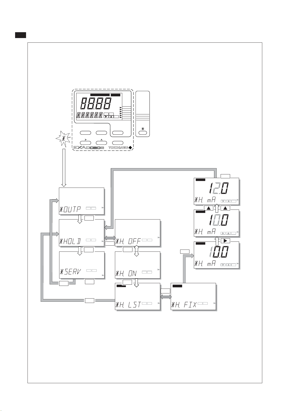
Parameter Setting 5-4
5-2-2. HOLD
mA
MODE
FAILTEMP.MAN
ppm
ppb
%sat
YES NO
NO MODEYES
CAL
OUTPUT
DISPLAY
ENT
ENT
HOLD
SET HOLD
SERVICE
NO
YES NO
NO
YES NO
NO
YES NO
NO
YES
YES
HOLD
NO
YES
YES NO
YES NO
YES NO
HOLD active
last measured
value.
NO
HOLD
YES
HOLD
HOLD
HOLD
ENT
ENT
ENT
ENT
Set HOLD "fixed value"
YES NO
IM 12J05C01-01E
Page 45

5-2-3. SERVICE
5-5 Parameter Setting
MODE
FAILTEMP.MAN
ppm
ppb
%sat
YES NO
NO MODEYES
CAL
OUTPUT
DISPLAY
ENT
ENT
HOLD
SET HOLD
SERVICE
mA
mA
NO
NO
NO
Example: Service Code 01
Select Sensor Type
YES
NO
YES
NO
Polarization voltage
and sensitivity.
Set using >, ,ENT keys.
>
ENT
ENT
ENT
YES
NO
ENT
ENT
for galvanic sensor
for polarographic
With the >, ,ENT keys
ENT
ENT
>
ENT
ENT
YES
ENT
ENT
IM 12J05C01-01E
Page 46

Parameter Setting 5-6
5-3. Notes for guidance in the use of service coded settings
Don't set or input service code numbers other than the code numbers defined in this manual. Setting an
undefined service code may make the transmitter malfunction.
When an undefined service code is input by some accident, push the MODE key and escape from the service level.
5-3-1. Parameter specific functions
Code 1 *S.TYPE Select 0 for DO30G sensor or any other galvanic sensor. Select 1 for Oxyferm,
Oxygold and other polarographic sensors.
*V.POL
*SENS Set the sensitivity of the connected sensor.
Code 4 *SAL.TY Enable or disable compensation. This function is particularly useful when
*[Cl-] Set level for salinity compensation.
5-3-2. Temperature functions
Code 10 *T.SENS Select temperature sensor to suit the measuring probe. The default selection is
Code 11 *T.UNIT Select °C or °F for temperature display.
Code 12 *T.ADJ Adjust offset in temperature measurement when the sensor is at a stable known
Code 13 *T.MAN Enable and set manual temperature compensation.
Set the polarization voltage of the connected sensor (only for polarographic sensors).
measuring in estuarine or brackish waters.
the 22k NTC sensor. Refer to the instructions delivered with the DO sensor to
check which temperature sensor is used.
value.
5-3-3. Calibration functions
Code 20 *T.SEC Set stability parameters for calibration. A greater time, and/or a smaller step gives
*Z.PPM greater stability before a calibration can be accepted. Use caution, however, to avoid
*Z.PPB very long calibration times.
*Z.SAT
*S.PPM
Code 21 *Z.CAL Normally not necessary, zero calibration can be enabled when required.
*Z.LIM Zero check limit.
Code 22 *ZERO Calibration values can be entered from independent (laboratory) data.
*SENS The sensitivity is the increase of the cell current per ppm and is specified in nA/
ppm at 25˚C (77˚F).
Sensor nominal sensitivity (nA/ppm at 25˚C)
DO30(G) 450
OXYFERM 7.5
OXYGOLD 35
IM 12J05C01-01E
Page 47

5-7 Parameter Setting
Code Display Function Function detail X Y Z Default values
Parameter Specific functions
01 *S.TYPE Sensor type Galvanic 0 1
Polarographic 1
*V.POL (Polarographic) 0.675 V
Polarization Voltage
*SENS Sensor sensitivity Polarographic 7.5 nA/ppm
Galvanic
04 *SAL.TY Salinity comp. Compensation disabled 0 0
Compensation enabled 1
*[Cl-] NaCl conc. Concentration in g/kg water: 0.0
range 1 to 99.9 g/kg
05-09 Not used
Code Display Function Function detail X Y Z Default values
Temperature Measuring Functions
10 *T.SENS Temp. Comp. Pt1000 RTD (DO30G) 0 1
22k NTC (Oxyferm) 1
Pb36 = 2k2 NTC (DO30) 2
11 *T.UNIT Temp units Celsius (°C) 0 0
Fahrenheit (°F) 1
12 *T.ADJ Temp adjust Adjustment +/- 7.5 °C or +/- 13.5 °F
13 *T.MAN Manual TC Automatic temperature comp 0 0
Manual temp compensation 1 25 °C/ 77 °F
14-19 Not used
450 nA/ppm (*S.TYPE=0)
Code Display Function Function detail X Y Z Default values
Calibration Settings
20 *T.SEC Stabilization Stabilization time range 5- 600 s 60 s
Step DO step change range 0-50 ppm
Z.PPM 0-1999 ppb 0.1 ppm (Z.PPM)
Z.PPB 1 ppb (Z.PPB)
Z.SAT 1.0 % SAT (Z.SAT)
S.PPM 0-600 %SAT 0.1 ppm (S.PPM)
(
always PPM
)
21 *Z.CAL Zero calibration Zero calibration disabled 0 0
Zero Calibration enabled 1
*Z.LIM Zero check limit Zero check limit (galv.)
0-19.99 A 19.99 A
Zero check limit (polar.)
0-199.9 nA 199.9 nA
22 *ZERO Zero current Offset range, 0 nA
±Zero Check Limit
*SENS Sensitivity entry Sensitivity range 1-1999 nA/ppm 7.5
450
nA
/ppm
nA
/ppm (*S.TYPE=0)
23-29 Not used
IM 12J05C01-01E
Page 48

Parameter Setting 5-8
mA
5-3-4. mA output functions
Code 31 *OUTP.F For the DO202 the output may be chosen as linear to input, or configured in a
Code 32 *BURN Diagnostic error messages can signal a problem by sending the output signals
Note: Burnout downscale can only be selected if the HART communication is turned of in service code 60.
Code 35 *TABLE The table function allows the configuration of an output curve by 21 steps
5-3-5. User interface
21 point table to a particular linearization. Enable the table setup in code 31, and
configure the table in code 35.
upscale (21 mA) or downscale (3.6 mA when HART comm. non-used, 3.9 mA
when HART comm. used). This is called upscale or downscale burnout, from
the analogy with thermocouple failure signaling of a burned-out or open circuit
sensor. The pulse burnout setting gives a 21 mA signal for the first 30 seconds
of an alarm condition. After the “pulse” the signal returns to normal. This allows a
latching alarm unit to record the error. In the case of the EXA the diagnostics are
extensive and cover the whole range of possible sensor faults.
(intervals of 5%). The following example shows how the table may be configured
to linearize the output with a mA curve.
Code 50 *RET When Auto return is enabled, the transmitter reverts to the measuring mode from
anywhere in the configuration menus, when no button is pressed during the set
time interval of 10 minutes.
Code 51 *P.MAN In Maintenance mode the pressure can be entered (M. PRESS).
*P.%
*P.CAL
Code 52 *PASS Passcodes can be set on any or all of the access levels, to restrict access to the
instrument configuration.
Code 53 *Err. xx Error message configuration. Two different types of failure mode can be set.
Hard fail gives a steady FAIL flag in the display.
Soft fail gives a flashing FAIL flag in the display. The call for maintenance is
a good example of where a SOFT fail is useful. A warning that the regular
maintenance is due, should not be used to shut down the whole measurement.
Code 55 *CALL.M Call for maintenance is a contact trigger to signal that the system has been in
service for longer than the set time without calibration. The user can set up to
250 days as a routine service interval.
Code 56 *UNIT Select ppm, ppb or % saturation as the main unit, to suit the application.
IM 12J05C01-01E
Page 49

5-9 Parameter Setting
mA
Code Display Function Function detail X Y Z Default values
Output Functions
30 Not used
31 *OUTP.F mA output functions Linear 0 0 Linear
Table 1
32 *BURN Burn function No burnout 0 0 No Burn.
Burnout downscale 1
Burnout upscale 2
Pulse burnout 3
33, 34 Not used
35 *TABLE Output table for mA
*0% Linearization table for mA in 5% steps.
*5% The measured value is set in the main
*10% display using the >, ^, ENT keys, for
... each of the 5% interval steps.
... Where a value is not known, that value may
*95% be skipped, and a linear interpolation will
*100% take place.
36-39 Not used
Code Display Function Function detail X Y Z Default values
User Interface
50 *RET Auto return No return to meas. from HOLD 0 1
Return to meas after 10 min 1
51 *P.MAN Manual pressure No manual pressure in Maint.mode 0 0
Manual pressure in Maint.mode 1
*P.% Enter Manual process pressure 0-999.9 kPa 101.3 kPa
*P.CAL Enter Cal. pressure in Maint.mode 0-999.9 kPa 101.3 kPa
52 *PASS Password Direct access to MAINT 0 0.0.0
Pass: 111 for #=1, MAINT protected by password #
333 for #=2, Direct access to COMM 0
777 for #=3, COMM protected by password #
888 for #=4, Direct access to SERV 0
123 for #=5, SERV protected by password #
957 for #=6,
331 for #=7,
546 for #=8 and
847 for #=9
53 *Err.01 Error setting Calibration not stable Soft fail 0
Calibration not stable Hard fail 1 1 Hard
*Err.02 Zero out of limits Soft fail 0
Zero out of limits Hard fail 1 1 Hard
*Err.07 Temperature sensor open Soft fail 0
Temperature sensor open Hard fail 1 1 Hard
*Err.08 Temp. sensor shorted Soft fail 0
Temp. sensor shorted Hard fail 1 1 Hard
*Err.09 Cell current abnormal Soft fail 0
Cell current abnormal Hard fail 1 1 Hard
*Err.16 Call for maintenance
Interval time exceeded
Call for maintenance Hard fail 1
Interval time exceeded
55 *CALL.M E16 setting No call for maintenance 0 0
Call for maint. enabled 1
*CALL .M E16 message after 1- 250 days 250
56 *UNIT PV unit Unit of measurement ppm 0 0
Unit of measurement ppb 1
Unit of measurement % sat. 2
57-59 Not used
Soft fail 0 0 Soft
IM 12J05C01-01E
Page 50

Parameter Setting 5-10
5-3-6. Communication setup
Code 60 *COMM. The settings should be adjusted to suit the communicating device connected
mA
to the output. The communication can be set to HART®.
*ADDR. Select address 00 for point to point communication with 4-20mA transmission.
Addresses 01 to 15 are used in multi-drop configuration (fixed 4mA output).
mA
Code 61 *HOUR The clock/calendar for the logbook is set for current date and time as reference.
*MINUT
*SECND
*YEAR
*MONTH
*DAY
Code 62 *ERASE Erase logbook function to clear the recorded data for a fresh start. This may be
desirable when re-commissioning an instrument that has been out of service for a
while.
5-3-7. General
Code 70 *LOAD The load defaults code allows the instrument to be returned to the default set up
with a single operation. This can be useful when wanting to change from one
application to another.
5-3-8. Test and setup mode
Code 80 *TEST Not used
Note: attempting to change data in service code 80 and above without the proper instructions and
equipment, can result in corruption of the instrument setup, and will impair the performance of the
unit.
IM 12J05C01-01E
Page 51

5-11 Parameter Setting
Code Display Function Function detail X Y Z Default values
Communication
60 *COMM. Communication Set HART® communication Off 0 1.0 On
mA
Set HART® communication On 1
Communication write enable 0 Write
Communication write protect 1 enable
*ADDR. Network address Set address 00 to 15 00
61 *HOUR Clock setup Adjust to current date and time using
mA
*MINUT >, ^ and ENT keys
*SECND
*YEAR
*MONTH
*DAY
62 *ERASE Erase logbook Press YES to clear logbook data
63-69 Not used
Code Display Function Function detail X Y Z Default values
General
70 *LOAD Load defaults Reset configuration to default values
71-79 Not used
Code Display Function Function detail X Y Z Default values
Test and setup mode
80 *TEST Test and setup Not used
IM 12J05C01-01E
Page 52

6. CALIBRATION PROCEDURE
Calibration Procedure 6-1
Calibration of the dissolved oxygen analyzer is performed in the following situations:
• When a new dissolved oxygen sensor is installed.
• When the membrane is replaced and/or the
electrolyte solution is replaced
• When the sensor has been disassembled and
reassembled for maintenance
• When the measuring error after cleaning exceeds
the acceptable deviation from reference method
• When error message E16 indicates the need for
maintenance
6-1. General
6-1-1. Calibration methods
There are four methods for calibration of the EXA
dissolved oxygen analyzer: air calibration, water
calibration, sensitivity and zero (offset) calibration.
Air calibration
This is the most common and easiest way to calibrate the analyzing system. The calibration is done
in AIR.CAL mode in maintenance level.
Water calibration
This is the traditional way to calibrate dissolved oxygen analyzers in laboratory environment. . Accurate
results can be obtained if the calibration is performed carefully. The water calibration may include
a zero calibration if so selected in service code 21.
Normally only a zero check is performed without
calibration, since a good sensor has no zero signal.
Water calibration is not possible in salt water unless
salinity compensation is activated in service code
04. The calibration is done in H2O.CAL mode in
maintenance level
Note: In normal industrial environments better
results are obtained with air calibration, which
is therefore the recommended method.
Manual calibration
This is a calibration method whereby the sensor is
not exposed to a calibration fluid, but is calibrated
by comparison with a reference method. This reference method is normally a laboratory analysis
of the water sample: either by Iodometric titration
according ISO 5813 or an electrochemical method
according ISO 5814.
The calibration is done in SENS/ZERO mode in
maintenance level.
6-1-2. Diagnostic functions performed during
calibration
The calibration is a semi-automatic calibration,
which means that the sensor output is used for
calculation of sensor parameters after the readings have stabilized. The criteria for stabilization
are set in service code 20. If stable readings are
not achieved within one hour error E1 message will
appear on the display and the procedure is aborted.
The calculated sensor parameters are compared
with preset tolerances and if these conditions are
not met, Error E2 (Zero Error) or E3 (Sensitivity
Error) will be signalled.
Notes:
1. Error messages that appear initially indicate
inadequate settings of the diagnostic variables
in service codes 01, 20 and/or 22.
2. Patience improves the accuracy of calibration.
When the EXA prompts the user that the
preset criteria are met by showing CAL.END
message it only means that the minimum
criteria are met. When the signal still changes
after this initial acceptance, EXA will
automatically update the sensor characteristics
with the new information.
IM 12J05C01-01E
Page 53

6-2 Calibration Procedure
6-2. Calibration procedure using air calibration
method
6-2-1. Preparation
Move the sensor to a maintenance site and wash
off any dirt on the membrane. Lightly wipe off any
remaining water from the membrane with a soft tissue.
Expose the sensor to the air in an environment
where there is no temperature change and no wind
6-2-2. Procedure for air calibration
Press the MODE key. CALIB appears in the display, and the
MODE
FAILTEMP.MAN
ppm
ppb
%sat
CAL
YES NO
ENT
NO MODEYES
ENT
YES
NO
DISPLAY
HOLD
OUTPUT
SET HOLD
SERVICE
YES
from *1
The instruments waits for
the reading to stabilise.
(The display flashes)
When reading Is stable,
the CAL END message
appears.
(a convenient way to accomplish this environment is
to place the sensor in an empty bucket).
Note: If sensors are used without temperature
compensating element, the temperature
must be adjusted to ambient temperature in
service code 13.
12J6B2-22
YES/NO key flags flash. Press YES.
Note: To start calibration with a zero oxygen
(N2 gas.)
NO
YES
NO
YES
ABLE
YES
NO
SC21=1
NO
NO
SC21=0
YES
YES
YES
NO
NO
NO
NO
NO
to *1
YES
NO
NO
YES
YES
NO
Press YES for single point
adjustment.
YES
YES
After briefly displaying WAIT,
the display returns
Go to
YES
6-3-3
NO
normal readout.
to the
NO
YES NO
YES
YES
to *1
Go to
YES
6-4-2
NO
Sensor can be returned
to process water.
Go to
YES
6-4-3
NO
IM 12J05C01-01E
Page 54

Calibration Procedure 6-3
6-3. Calibration procedure using water calibra-
tion method
6-3-1. Preparation
Move the sensor to a maintenance site and wash
off any dirt on the membrane. Lightly wipe off any
remaining water from the membrane with a soft tissue.
Prepare the necessary equipment and reagents to be
used for the span and (if required) zero calibration.
Equipment for span calibration includes:
• Beaker or bucket
•
Magnetic stirrer or other means of agitating the water
• Demineralized water or salty process water if
salinity compensation is activated
• Air supply pump (aquarium pump)
• Glass diffuser to generate small air bubbles
Note: It takes 15 to 30 minutes of aeration before
it can be assumed that the water is fully
saturated with air.
Reagent for zero calibration:
• Sodium sulfite
• demineralized water
The zero oxygen solution contains 20- 30 grams of
sodium sulfite per liter.
6-3-2. Calibration operation
(water calibration method)
6-3-3. Procedure for water calibration
MODE
FAILTEMP.MAN
ppm
ppb
%sat
CAL
YES NO
NO MODEYES
YES
NO
OUTPUT
DISPLAY
ENT
SET HOLD
HOLD
SERVICE
ENT
YES
Press the MODE key. CALIB appears in the display, and the
YES
from *1
The instruments
waits for the
reading to
stabilise.
(The display
flashes). When
reading Is stable,
the CAL END
message
appears.
If both zero and span calibration are used, it is better to start with span calibration in spite of normal
calibration sequence with analog instrumentation.
Otherwise the sensor must be rinsed off carefully to
prevent ingress of oxygen absorbing sulfite in the
aerated water.
Note: Zero calibration in the sodium sulfite solution
takes a long time. Even after CAL.END
prompt it is necessary to wait 40-50 minutes
before zero adjustment can be made.
Otherwise calibration errors are introduced in
the measurement. It is recommended not to
do a zero calibration, but a zero check only.
A good clean sensor does not have a zero
current and does not require zero calibration.
If the sensor has a substantial zero current,
the sensor has to be disassembled, cleaned
and filled with fresh electrolyte solution and a
new membrane has to be fitted.
Calibration may take longer than 10 minutes.
Before starting the calibration procedure,
check the setting of Auto Return (*RET.) in
Service Code 50. It is recommended to set
the Auto Return to “0” (No return to meas.
from HOLD). After the calibration procedure
has been completed, set the Auto Return to
the desired setting in Service Code 50.
YES/NO key prompt flags flash. Press YES.
NO
YES
YES
Note: To start calibration with a zero solution
(zero-dissolved-oxygen solution.)
NO
SC21=1
YES
NO
NO
NO
SC21=0
YESYES
YES
NO
IM 12J05C01-01E
NO
Go to
6-4-2
Go to
6-4-3
to *1
After briefly displaying WAIT,
the display returns
Sensor can be returned
YES
NO
NO
YES
NO
NO
YES
NO
NO
NO
YES
NO
YES
YES
normal readout.
to process water.
Press YES for single point
NO
adjustment.
to the
NO
to *1
YESYES
YES NO
YESYES
Page 55
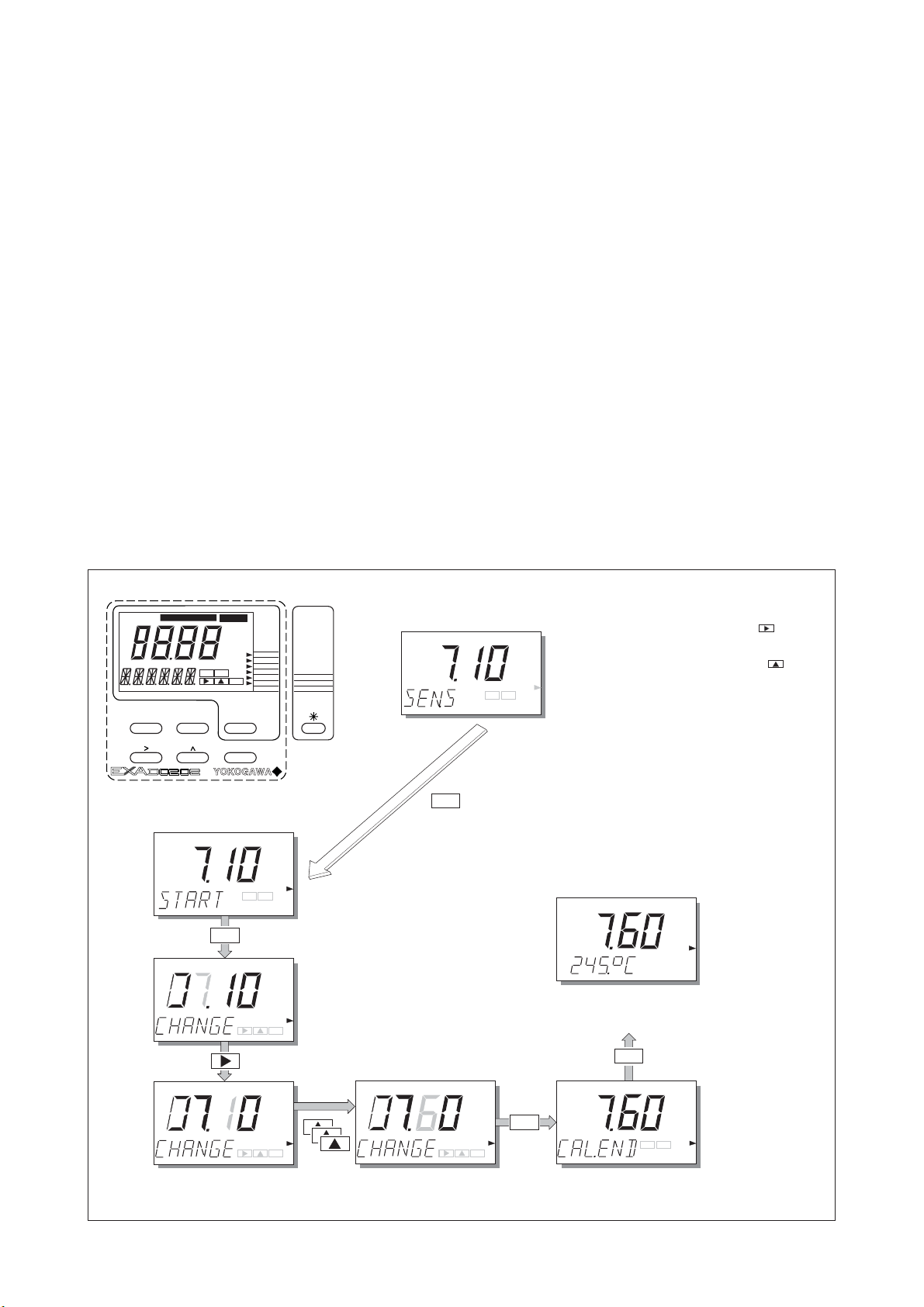
6-4 Calibration Procedure
6-4. Calibration procedure using manual calibra-
tion method
6-4-1. Preparation
A. Cleaning
Confirm that the readings of the analyzer are
stable and measured with a clean sensor.
Otherwise move the sensor to a maintenance site
and wash off any dirt on the sensor membrane
Move the sensor back to the process water and
wait for the readings to stabilize.
B. Sampling
The manual calibration procedure involves
adjustment of the readings to a reference standard.
Normally this reference is a laboratory
measurement that analyses a sample that must
be identical to the sample measured with the online analyzer.
6-4-2. Procedure for manual slope (sensitivity) calibration
The following precautions must be taken into
account:
• The sample must be analyzed directly after
sampling to avoid change of dissolved oxygen
concentration or temperature after sampling
• The reference standard must be analyzed with
a laboratory meter that is calibrated prior to
sample analysis
• The reference method must be calibrated with
the same calibration data as specified in ISO
5814 to avoid indiscrepancies
Most important calibration data are:
Dissolved oxygen concentration at saturation
conditions as function of temperature, barometric
pressure, altitude and salinity.
These data are included in this manual for
reference and verification of correct calibration of
reference analyzers. DO202 has taken all these
variables into account during the semi-automatic
calibration methods.
MODE
FAILTEMP.MAN
ppm
ppb
%sat
YES NO
NO MODEYES
CAL
OUTPUT
DISPLAY
ENT
ENT
HOLD
SET HOLD
SERVICE
YES
YES
NO
Select the flashing digit with the key.
Increase its value by pressing the key.
When the correct value is displayed,
press
ENT to enter the change.
Press YES to return to the
measuring mode. (Single Point
adjustment only)
YES
YES
NO
After briefly displaying WAIT,
the display returns to
ENT
the normal readout.
YES
ENT
ENT
ENT
NOYES
IM 12J05C01-01E
Page 56

6-4-3. Procedure for manual zero (offset) calibration
MODE
FAILTEMP.MAN
ppm
ppb
%sat
YES NO
NO MODEYES
CAL
OUTPUT
DISPLAY
ENT
ENT
YES
HOLD
SET HOLD
SERVICE
NO
YES
Calibration Procedure 6-5
YES
NO
YES
ENT
ENT
Select the flashing digit with the key.
Increase its value by pressing the key.
When the correct value is displayed, press ENT to enter the change.
ENT
ENT
NOYES
YES
After briefly displaying WAIT,
the display returns to
the normal readout.
Press YES to return to the
measuring mode. (Single Point
adjustment only)
IM 12J05C01-01E
Page 57

6-6 Calibration Procedure
Table 6-1. Solubility of oxygen (mg/l) in water as a function of temperature & salinity (ISO 5814)
Temp Solubility of oxygen in water in equilibrium Correction to be substracted for each degree of salinity
with air expressed in grams per kilogram of total salts in water
@101.325kPa[pO2] [∆pO2]
°C mg/l (ppm) mg/l (ppm)
0 14.62 0.0875
1 14.22 0.0843
2 13.83 0.0818
3 13.46 0.0789
4 13.11 0.0760
5 12.77 0.0739
6 12.45 0.0714
7 12.14 0.0693
8 11.84 0.0671
9 11.56 0.0650
10 11.29 0.0632
11 11.03 0.0614
12 10.78 0.0593
13 10.54 0.0582
14 10.31 0.0561
15 10.08 0.0545
16 9.87 0.0532
17 9.66 0.0514
18 9.47 0.0500
19 9.28 0.0489
20 9.09 0.0475
21 8.91 0.0464
22 8.74 0.0453
23 8.58 0.0443
24 8.42 0.0432
25 8.26 0.0421
26 8.11 0.0407
27 7.97 0.0400
28 7.83 0.0389
29 7.69 0.0382
30 7.56 0.0371
Table 6-2. Solubility of oxygen (mg/l) at various
temperatures and elevations (based on sea level barometric
pressure of 760 mm Hg)
Temp Elevation (metres above sea level)
°C 0 300 600 900 1200 1500 1800
0 14.6 14.1 13.6 13.2 12.7 12.3 11.8
2 13.8 13.3 12.9 12.4 12.0 11.6 11.2
4 13.1 12.7 12.2 11.9 11.4 11.0 10.6
6 12.4 12.0 11.6 11.2 10.8 10.4 10.1
8 11.8 11.4 11.0 10.6 10.3 9.9 9.6
10 11.3 10.9 10.5 10.2 9.8 9.5 9.2
12 10.8 10.4 10.1 9.7 9.4 9.1 8.8
14 10.3 9.9 9.6 9.3 9.0 8.7 8.3
16 9.9 9.5 9.2 8.9 8.6 8.3 8.0
18 9.5 9.2 8.9 8.6 8.3 8.0 7.7
20 9.1 8.8 8.5 8.2 7.9 7.7 7.4
22 8.7 8.4 8.1 7.8 7.6 7.3 7.1
24 8.4 8.1 7.8 7.6 7.3 7.1 6.8
26 8.1 7.8 7.6 7.3 7.0 6.8 6.6
28 7.8 7.5 7.3 7.0 6.8 6.6 6.3
30 7.5 7.2 7.0 6.8 6.5 6.3 6.1
32 7.3 7.1 6.8 6.6 6.4 6.1 5.9
34 7.1 6.9 6.6 6.4 6.2 6.0 5.8
36 6.8 6.6 6.3 6.1 5.9 5.7 5.5
38 6.6 6.4 6.2 5.9 5.7 5.6 5.4
40 6.4 6.2 6.0 5.8 5.6 5.4 5.2
Table 6-3. Solubility of oxygen (mg/l) of sea water & fresh
water (based on sea level barometric pressure of 760 mm Hg)
Temp Solubility
Sea water Fresh water
°C mg/l (ppm) mg/l (ppm)
0 11.97 14.62
2 11.36 13.84
4 10.82 13.13
6 10.29 12.48
8 9.84 11.87
10 9.43 11.33
12 9.05 10.83
14 8.69 10.37
16 8.37 9.95
18 8.06 9.54
20 7.77 9.17
22 1.48 8.83
24 7.21 8.53
26 6.93 8.22
28 6.67 7.92
30 6.41 7.63
IM 12J05C01-01E
Page 58

7. MAINTENANCE
Maintenance 7-1
It is important for maintaining the measurement
accuracy of the EXA DO series of wire dissolvedoxygen metering system to perform inspection and
maintenance at fixed intervals. It also serves to pre-
7-1-1. Inspection and maintenance to be imple-
mented periodically
Table 7-1. shows the items which are recommended
to be inspected and maintained periodically.
vent problems from arising.
This chapter describes daily inspection and maintenance for the purpose of maintaining system performance.
7-1-2. Inspection and maintenance to be imple-
mented on occasion
Occasionally implement the maintenance that is not
directly related to measurement functions and main-
7-1. Overall dissolved-oxygen metering system
tenance associated with errors.
Tables 7-1 and 7-2 show the inspection and maintenance items for equipment composing dissolvedoxygen metering system. The procedure of inspection and maintenance for the dissolved-oxygen
transmitter is described in Section 7-2. For inspection and maintenance of the sensors and holders,
see each instruction manual respectively.
Table 7-1. Items for periodic inspection and maintenance of dissolved-oxygen metering system
Instrument or apparatus Item Recommended Interval
All equipment a. Calibration a. 1 to 2 months
Dissolved oxygen sensor a. Cleaning of membrane a. 1 to 2 months
b. Polishing of silver electrode b. 6 to 8 months
surface and replacement of electrolyte
c. Replacement of membrane assembly c. 6 to 8 months
Dissolved oxygen transmitter a. Inspection of temperature indication a. 6 months
(error check)
Float holder a. Sweeping of winch mechanism a. (depends on installation environment)
Immersion holder a. Inspection of sensor holding O-ring a. 6 months
b. Sweeping of cleaner nozzle b. 1 to 2 months
c. Inspection for leakage from the solenoid c. 6 months
valve for cleaning utility
7-2. Periodic maintenance for the EXA DO202
transmitter
The DO202 transmitter requires very little periodic maintenance. The housing is sealed to IP65
Note: Never used harsh chemicals or solvents. In
the event that the window becomes heavily
stained or scratched, refer to the parts list
(Chapter 9) for replacement part numbers.
(NEMA 4X) standards, and remains closed in normal
operation. Users are required only to make sure the
front window is kept clean in order to permit a clear
view of the display and allow proper operation of the
pushbuttons. If the window becomes soiled, clean it
using a soft damp cloth or soft tissue. To deal with more
stubborn stains, a neutral detergent may be used.
When you must open the front cover and/or glands,
make sure that the seals are clean and correctly fitted when the unit is reassembled in order to maintain
the housing’s weatherproof integrity against water and
water vapor. The DO measurement uses small signal
currents and may otherwise be prone to problems
caused by exposure of the circuitry to condensation.
Table 7-2. Items for occasional inspection and maintenance of dissolved-oxygen metering
Faulty phenomenon System content of inspection
Error E2 occurrence Check whether the dissolved oxygen sensor membrane is contaminated or not.
Check whether the nozzle is clogged or not.
Error E3 occurrence Polish the silver electrode surface of the dissolved oxygen sensor and replace the
electrolyte.
It is difficult to see the inside of the transmitter Wipe off the dirt on the transparent window using tissue paper or
through the window the like. (Use detergent for hard-to-clean dirt.)
IM 12J05C01-01E
Page 59

8. TROUBLESHOOTING
8-1 Troubleshooting
This chapter describes the countermeasures for failures, classifying the cases into three categories: dissolved-oxygen transmitter failure, detection of failure with the self-diagnosis function, and abnormal
measured values. The causes for abnormal measured values are not limited to equipment failures. If
an abnormal phenomenon occurs, first check the
following items:
• Is the property of the measuring solution different
from normal?
8-1. Measures in the case of transmitter opera-
tion failure
If the operation keys do not operate smoothly or the
display fails (e.g., a missing character segment),
repair of the printed circuit board (digital board) or
replacement with a new one is required.
After the printed circuit board is replaced, operation checks and parameter settings are necessary.
Contact Yokogawa and request board-replacement
work.
• Is the dissolved-oxygen sensor properly installed?
8-2. Measures in the case of failure (Error) detection
Table 8-1. Measures in the case of failure (Error) detection
Error Generation Error Content and Causes Measures
No. Mode
E 1 AIR.CAL mode Stability failure Eliminate the causes and press the
H20. CAL mode Even after an hour has elapsed, the (NO) key to perform re calibration.
measured value change does not decrease
within the set value of ppm
• Sensor temperature changes.
• Dissolved-oxygen of the calibration solution changes.
• The value of ppm is not suitable.
E 2 H20. CAL mode Zero error failure Clean the sensor membrane and
MAN.CAL mode The zero error exceeds the set range recalibrate. If the error is detected again,
(ZERO) • Dirt sticks to the sensor membrane. replace the electrolyte and the membrane.
• Membrane abnormality. Electrolyte degradation.
E 3 AIR.CAL mode Sensitivity failure Clean the sensor membrane and
H20. CAL mode The sensitivity exceeds the range of recalibrate. If the error is detected again,
MAN.CAL mode 1 - 1999 nA/ppm. replace the electrolyte and the membrane.
(SENS) • Dirt sticks to the sensor membrane.
• Membrane abnormality. Electrolyte degradation.
E 7 All modes Measured temperature failure (too high) Examine the temperatures of the
It exceeds 150.0 °C (302 °F). measuring solution and sensor and the
• Measuring solution temperature is high CODE 10 setting
• CODE 10 setting is not correct Examine the sensor cable connection
• Sensor cable wiring failure status.
• Temperature sensor has failed If the temperature sensor fails (abnormal
resistance), replace the sensor.
E 8 All modes Measured temperature failure (too low) Examine the temperatures of the
It falls below -20 °C (or -4 °F). measuring solution and sensor
• Measuring solution temperature is low and the CODE 10 setting.
• CODE 10 setting is not correct Examine the sensor cable connection
• Sensor cable wiring failure status.
• Temperature sensor has failed. If the temperature sensor fails (abnormal
resistance), replace the sensor.
E 9 All modes Input current failure Examine the setting for CODE 01, 022
It does not satisfy the following equation:
input current < 50 A for galvanic sensor
< 1200 nA for polarographic sensor
IM 12J05C01-01E
Page 60

Troubleshooting 8-2
Error Generation Error content and Causes Measures
No. Mode
E10 All modes EEPROM writing failure Turn off the power and then turn it
Electronic circuit failure back on and check whether or not the
system returns to normal.
If the failure occurs again, contact
Yokogawa to request repair.
E15 CODE 11 Temperature error correction failure Accurately measure the temperature of
The difference between the corrected value the measuring solution (dissolved oxygen
and the standard value exceeds the range sensor).
corresponding to ±7.5°C (±13 5°F). Examine whether the sensor cable fails
• Temperature entry is not accurate. (partial disconnection or degraded
• Sensor cable failure insulation) and then correct the
temperature error again.
E16 All modes Call for maintenance-interval time exceeded Perform maintenance. Reset interval.
mA
E17 *OUTP Output span too small. Re-enter a value within the permissible range.
CODE 35 Min. span is 1ppm, 25ppb or 10%
mA
E18 CODE 35 Table values make no sense. Reprogram.
E19 At data entry Configuration failure Re-enter a value within the permissible
A value not within the permissible range is entered. range.
E20 All modes Instrument initialization failure Contact Yokogawa
E21 All modes EPROM comparison failure Contact Yokogawa
Note: It is possible that the error message does
not disappear immediately after corrective
measures.
Then turn power off and the turn it back on
and check whether the system returns to
normal.
IM 12J05C01-01E
Page 61

9. SPARE PARTS
See Customer Maintenance Parts List.
9-1 Spare Parts
Figure 9-1. Exploded view
IM 12J05C01-01E
Page 62

APPENDIX 1. USER SETTINGS
A-1-1. User setting table
FUNCTION SETTING DEFAULTS USER SETTINGS
Parameter specific functions
01 *S.TYPE 1 Polarographic
*V.POL 0.675 V
*SENS 7.5 nA/ppm
04 *SAL.TY 0 Off
*[Cl-] 0 g/kg
Temperature measuring functions
10 *T.SENS 1 22k NTC
11 *T.UNIT 0 °C
12 *T.ADJ None
13 *T.MAN 0 Off
Calibration parameter functions
20 *T.SEC 60 sec.
*Z.PPM 0.1 ppm
*Z.PPB 1 ppb
*Z.SAT 1.0 %
*S.PPM 0.1 ppm
21 *Z.CAL 0 Off
*Z.LIM 199.9 nA (polar)
22 *ZERO 0 A (nA)
*SENS 7,5 nA/ppm
mA
mA outputs
31 *OUTP.F 0 Linear ppm
32 *BURN 0 No Burn
35 *TABLE 0 to 20 ppm
User Interface
50 *RET 1 on
51 *P.MAN 0 off
*P.% 101.3 kPa
*P.CAL 101.3 kPa
52 *PASS 0.0.0 all off
53 *Err.01 1 hard fail
*Err.02 1 hard fail
*Err.07 1 hard fail
*Err.08 1 hard fail
*Err.09 1 hard fail
*Err.16 0 soft fail
55 *CALL.M 0 Off
*CALL.M 250 days
56 *UNIT 0 ppm
Communication
mA
60 *COMM. 1.0 on/write enable
*ADDR. 00
mA
61 *HOUR
62 *ERASE
General
70 *LOAD
Test and setup mode
80 *TEST
Appendix 1-1
IM 12J05C01-01E
Page 63

1-2 Appendix
A-1-2 Configuration Checklist for DO202
Standard configuration Options Reference for change
Measured variable(s)
Primary inputs DO and Temp
DO units ppm ppb. % saturation code 56
Temperature unit Celsius Fahrenheit code 11
mA
mA Outputs
Analog output 4-20mA for ppm ppb or %sat code 56, 31
Output linearization disabled ppm, ppb or %sat code 35
Burn out disabled burn low (3.6) / high (21) on mA output code 32
mA
Communication
Digital interface HART disabled code 60
Communication software external HHC contact factory
Interface
Variables on display ppm and temp %sat, °C, SE, ZR, REL “display”
Password protection disabled for mains/ comm./ serv level code 52
Autoreturn return to measure in 10 minutes enable or disable code 50
Add. functions in MAINT disabled manual pressure code 51
Diagnostics
Check on Slope active 1-1999 na/ppm code 22
Check on zero disabled enable or disable code 02, 21, 22
Check on stability 0.1 ppm per 60 s 0-50 ppm in 5-600 s code 20
Compatibility
DO sensor SM31 DO30G code 01, 10
Temperature sensor 22k NTC Pt 1000 code 10
Sensor principle polarographic galvanic code 01, “wiring”
Manual temp. comp. disabled disable or enable code 13
Special Features
Salinity compensation disabled comp. for 1-99.9 ppt NaCI code 04
Temperature calibration none adjustment ±7.5 °C or ±13.5°F code 12
Zero calibration disabled disable or enable code 21
Atm. press. compensation manual
Soft fail alarm disabled possible for E1..E2, E7..E9, E16 code 53
Logbook disabled 2 volumes of 50 events code 61,62
A-1-3 HART process variables
mA
Through HART the user has access to the process
variables:
PV: User selected process value: ppm, ppb or %
saturation
SV: Temperature
TV: % Saturation
QV: sensor current
with two 0- 20 or 4- 20 mA outputs and three contact
outputs with 24 VDC power supply.
Full communication with the DO202 can be done
through various brands of HART Handheld terminals (HHT) or through Pactware. This program and
the Yokogawa DTM library can be downloaded
from YOKOGAWA WEB sites free of charge by
Yokogawa customers.
Each of these process variables can be decoded into
current output or contact output through the HIM: Hart
Yokogawa recommends the use of MH-02 modem
for HART-RS232 conversion.
Interface Module. Yokogawa offers standard a HIM
IM 12J05C01-01E
Page 64
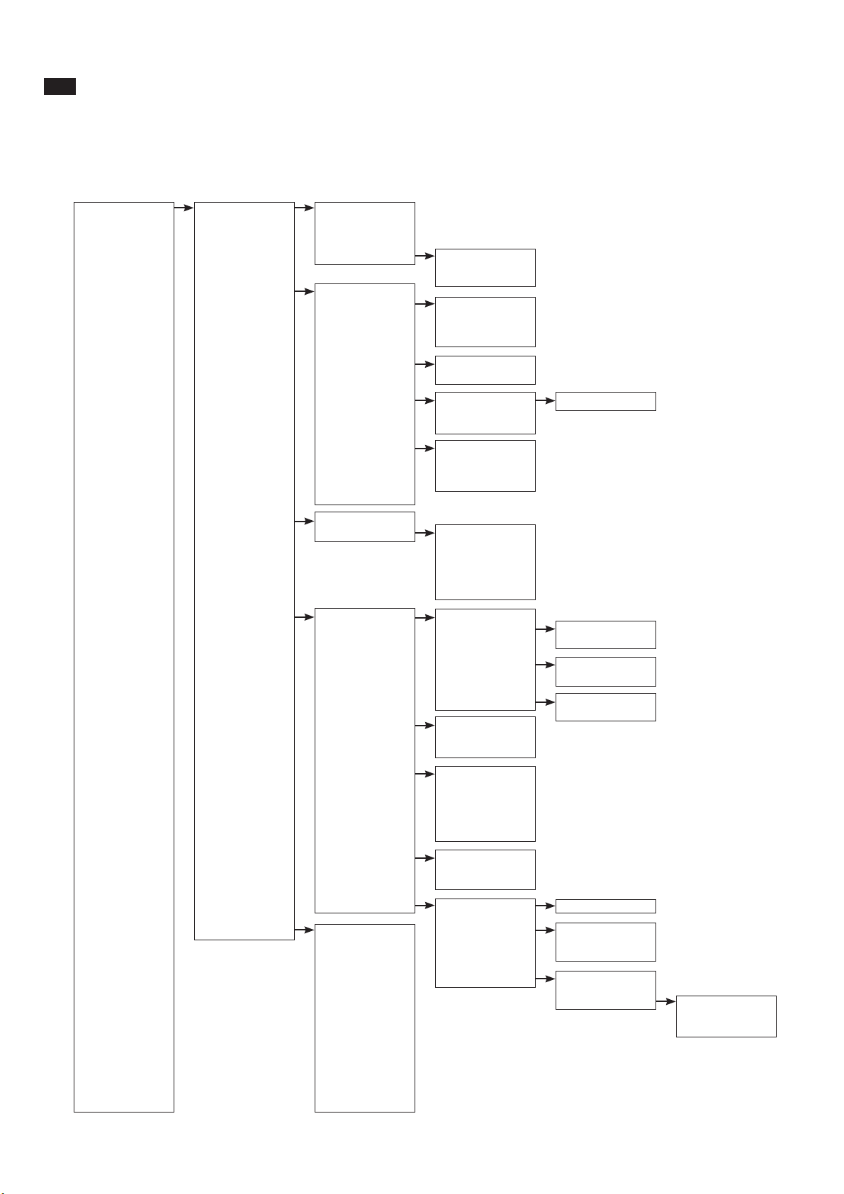
Appendix 1-3
A-1-4 Device description (DD) menu structure
mA
The Device Description (DD) is available from Yokogawa or the HART® foundation. An example is shown
below of the ON LINE menu structure. This manual makes no attempt to explain the operation of the Hand
Held Communicator (HHC). For detailed operating instructions, refer to the HHC instruction manual and the
on-line help structure.
Online menu Level 1 menu Level 2 menu Level 3 menu Level 4 menu Level 5 menu
Device setup Process variables PV
%sat
Temp
PV % rnge
More process var. Cell cur
Sens.
Zero cur
Diag/Service/Cal Status
Hold Hold func.
Hold type
Hold fix
Hold status
Manual temperature Temp.meas.
Man.temp.
Logbook Logbook config. Event1...Event27
Logbook1
Logbook2
Calibrate Zero cal.
Sample cal.
Zero cal.
Temp. cal.
Loop test
Basic setup Tag
Device information Date
Descriptor
Message
Write protect
Manufacturer
Dev id
Detailed setup DO measurement PV meas.
Sensor type Sensor
Pol. volt
Pressure specific %satpres
Cal.pres
Salinity comp. Sal.comp.
Salinity
Temp.specific Temp.sens
Temp.unit
Temp.adj
Cal. specific Sens.
Zero cur.
Zero lim.
Stab.time
Stab.Zero
Stab.Span
Output function mA funct.
Burn funct.
mA-table
User Interface Error prog. Error1...Error16
Review Model Maintenance Maint.Timer
Manufacturer M.time
Primary value Distributor M.due in
Analog output Tag
Lower range value Descriptor Display Auto.Ret
Upper range value Message Man.press.en.
Date Passcodes Maintenance
Dev id Commissioning
Write protect Service
Universal rev
Fld dev rev
Software rev
Hardware rev
Poll addr
Num req preams
(Note):HART protocol DD files can be downloaded by following URL.
IM 12J05C01-01E
http://www.yokogawa.com/an/download/an-dl-fieldbus-001en.htm
Page 65

IM 12J05C01-01E
Page 66

APPENDIX 2. QUALITY INSPECTION
A-2-1. DO202G 2-Wire Dissolved Oxygen Transmitter
Appendix 2-1
Quality
Inspection
DO202G
Dissolved Oxygen Transmitter
Standards
1. Scope
This inspection standard applies to the DO202G Dissolved Oxygen Transmitter.
2. Inspection Items
2.1 Insulation resistance test
2.2 Current output test
2.3 Temperature indication check
* 2.4 Galvanic indication check
* 2.5 Polarograph indication check
Note: Items marked with an asterisk (*) may only be confirmed by a test certificate.
3. Inspection Methods, Standards and Conditions
z Connect the testing circuit as shown in Figure 1. Allow the instrument to warm up for at least
5 minutes before conducting the tests. For the connections for the insulation resistance test,
follow the instructions in Section 3.1.
z Performance tests should be done in the inspection mode where the tests from Section 3.2
through Section 3.5 take place in sequence and cannot be retraced. If the reconfirmation of
a test is needed, turn off the power to the transmitter, turn on the power again, and enter the
inspection mode to restart the tests.
3.1 Insulation Resistance Test
(1) Apply 500 V DC between the power supply terminals shorted together (+ and –) and the
earth terminal (G). The insulation resistance must be 100 M or greater.
(2) Apply 500 V DC between the input terminals shorted together (11 to 18) and the earth
terminal (G). The insulation resistance must be 100 M or greater.
3.2 Current Output Test
Connect the testing circuit as shown Figure 1 and set the equipment as follows:
Decade resistance box: 1019.5 []
DC generator 1: 0 A
DC generator 2: 0 A
DC source: 24 V DC
User the following procedure to enter the inspection mode.
(1) Entering Service Code 87.
a. Press the [] key. The message display will show “OUTP.”
b. Press the [NO] key twice. The message display will show “SERV.”
c. Press the [YES] key. The data display will show “00” with the first digit of 0 flashing.
d. Press the [
flashing.
e. Press the [>] key once. The data display will show “80” with the second digit of 0
flashing.
f. Press the [
flashing.
g. Press the [ENT] key. The message display will show “PASS.”
] key eight times. The data display will show “80” with the first digit of 8
] key seven times. The data display will show “87” with the second digit of 7
IM 12J05C01-01E
QIS 12J05C01-01E
1st Edition: Feb. 2007
Page 67

2-2 Appendix
(2) Setting Password 070.
(3) Confirming the date and time.
This is the inspection mode. When the message display shows “mA,” check the current outputs.
Each time the [ENT] key is pressed, the value on the data display increase in steps of 4.0 like
“4.0,” and “8.0.” Check the current outputs. Corresponding to the data display, the current
output must be within the range shown in Table 1.
2/3
a. Press the [>] key once. The data display will show “000” with the second digit of 0
flashing.
b. Press the [
7 flashing.
c. Press the [ENT] key. The message display will show “HIF.”
d. Press the [YES] key.
a. Press the [ENT] key. The data display will show the date in day, month, year format.
b. Press the [ENT] key. The data display will show the time in hour, minute, second format.
c. Press the [ENT] key. The message display will show “mA.”
Table 1
] key seven times. The data display will show “070” with the second digit of
Data Display Current Output (mA DC)
4.0 4 ±0.02
12.0 12 ±0.02
20.0 20 ±0.02
3.3 Temperature Indication Check
Following Section 3.2, press the [ENT] key until the message display shows “22kNTC.” in this
state, change the resistance of the decade resistance box and check the data display. The
value on the data display must be within the range shown in Table 2.
Table 2
Temperature (°C)
-9 99.6k -9 ±0.3
25 22k 25 ±0.3
140 653.8 140 ±0.3
3.4 Galvanic Indication Check
Following Section 3.3, press the [ENT] key until the message display shows “GALVA.” Then
turn SW1 on. Change the current of the DC generator 1 and check the data display. The value
on the data display must be within the range shown in Table 3.
Table 3
Reference (A) Data Display (A)
10 10 ±0.06
30 30 ±0.1
50 50 ±0.2
3.5 Polarograph Indication Check
Press the [ENT] key until the message display shows “POLAR.1.” Then turn SW1 off. Change
the current of the DC generator 2 and check the data display. The value on the data display
must be within the range shown in Table 4.
Decade Box Resistance (:)
Data Display (°C)
QIS 12J05C01-01E
IM 12J05C01-01E
Page 68

Appendix 2-3
3/3
Table 4
Reference (nA) Data Display (nA)
2 2 ±0.02
6 6 ±0.04
12 12 ±0.07
Press the [ENT] key. The message display will show “POLAR.2.” Change the current of the DC
generator 2 and check the data display. The value on the data display must be within the range
shown in Table 5.
Table 5
Reference (nA) Data Display (nA)
20 20 ±0.1
60 60 ±0.3
100 100 ±0.5
Press the [ENT] key. The message display will show “POLAR.3.” Change the current of the DC
generator 2and check the data display. The value on the data display must be within the range
shown in Table 6.
Table 6
Reference (nA) Data Display (nA)
200 200 ±1
600 600 ±3
1000 1000 ±5
Press the [ENT] key until the message display shows “READY.” Press the [ENT] key again to
finish the tests.
DO202G
SUPPLY TEMP
+
+
DC Source
24 V DC
G 11 12 16 15 13 18 14 17
-
+
DC
Ammeter
-
300 :
Decade
Resistance
Box
Figure 1 Testing Circuit and Test Equipment
+
-
+
DC
Generator 1
+SH
-
GALV SENS POL SENS
SW1
-
+
DC
Generator 2
Shorting bar
IM 12J05C01-01E
QIS 12J05C01-01E
Page 69

2-4 Appendix
IM 12J05C01-01E
Page 70

A-2-2. DO202S 2-Wire Dissolved Oxygen Transmitter
Appendix 2-5
Quality
Inspection
DO202S
Dissolved Oxygen Transmitter
Standards
1. Scope
This inspection standard applies to the DO202S Dissolved Oxygen Transmitter.
2. Inspection Items
2.1 Insulation resistance test
* 2.2 Dielectric strength test
2.3 Current output test
2.4 Temperature indication check
* 2.5 Galvanic indication check
* 2.6 Polarograph indication check
Note: Items marked with an asterisk (*) may only be confirmed by a test certificate.
3. Inspection Methods, Standards and Conditions
z Connect the testing circuit as shown in Figure 1. Allow the instrument to warm up for at least
5 minutes before conducting the tests. For the connections for the insulation resistance test,
follow the instructions in Section 3.1, and for the connections for the dielectric strength test,
follow the instructions in Section 3.2.
z Performance tests should be done in the inspection mode where the tests from Section 3.3
through Section 3.6 take place in sequence and cannot be retraced. If the reconfirmation of
a test is needed, turn off the power to the transmitter, turn on the power again, and enter the
inspection mode to restart the tests.
3.1 Insulation Resistance Test
(1) Apply 500 V DC between the power supply terminals shorted together (+ and –) and the
earth terminal (G). The insulation resistance must be 100 M or greater.
(2) Apply 500 V DC between the input terminals shorted together (11 to 18) and the earth
terminal (G). The insulation resistance must be 100 M or greater.
3.2 Dielectric Strength Test
Apply 600 V AC, an AC voltage of substantially sinusoidal waveform with a frequency of 50 Hz
or 60 Hz, between the terminals shown below, for at least 2 seconds. The insulation must
withstand this voltage. (The sensed current should be 10 mA.)
(1) Between the power supply terminals shorted together (+ and –) and the earth terminal (G)
(2) Between the input terminals shorted together (11 to 18) and the earth terminal (G)
(3) Between the input terminals shorted together (11 to 18) and the power supply terminals
shorted together (+ and –)
3.3 Current Output Test
Connect the testing circuit as shown Figure 1 and set the equipment as follows:
Decade resistance box: 1019.5
DC generator 1: 0 A
DC generator 2: 0 A
DC source: 24 V DC
User the following procedure to enter the inspection mode.
IM 12J05C01-01E
QIS 12J05C01-21E
1st Edition: Feb. 2007
Page 71

2-6 Appendix
(1) Entering Service Code 87.
(2) Setting Password 070.
a. Press the [] key. The message display will show “OUTP.”
b. Press the [NO] key twice. The message display will show “SERV.”
c. Press the [YES] key. The data display will show “00” with the first digit of 0 flashing.
d. Press the [
flashing.
e. Press the [>] key once. The data display will show “80” with the second digit of 0
flashing.
f. Press the [
flashing.
g. Press the [ENT] key. The message display will show “PASS.”
a. Press the [>] key once. The data display will show “000” with the second digit of 0
flashing.
b. Press the [
7 flashing.
c. Press the [ENT] key. The message display will show “HIF.”
d. Press the [YES] key.
] key eight times. The data display will show “80” with the first digit of 8
] key seven times. The data display will show “87” with the second digit of 7
] key seven times. The data display will show “070” with the second digit of
2/4
(3) Confirming the date and time.
a. Press the [ENT] key. The data display will show the date in day, month, year format.
b. Press the [ENT] key. The data display will show the time in hour, minute, second format.
c. Press the [ENT] key. The message display will show “mA.”
This is the inspection mode. When the message display shows “mA,” check the current outputs.
Each time the [ENT] key is pressed, the value on the data display increase in steps of 4.0 like
“4.0,” and “8.0.” Check the current outputs. Corresponding to the data display, the current
output must be within the range shown in Table 1.
Table 1
Data Display Current Output (mA DC)
4.0 4 ±0.02
12.0 12 ±0.02
20.0 20 ±0.02
3.4 Temperature Indication Check
Following Section 3.3, press the [ENT] key until the message display shows “22kNTC.” In this
state, change the resistance of the decade resistance box and check the data display. The
value on the data display must be within the range shown in Table 2.
Table 2
Temperature (°C)
–9 99.6k –9 ±0.3
25 22k 25 ±0.3
140 653.8 140 ±0.3
Decade Box Resistance (:)
Data Display (°C)
QIS 12J05C01-21E
IM 12J05C01-01E
Page 72

3.5 Galvanic Indication Check
Following Section 3.4, press the [ENT] key until the message display shows “GALVA.” Then
turn SW1 off. Change the current of the DC generator 1 and check the data display. The value
on the data display must be within the range shown in Table 3.
Table 3
Reference (A) Data Display (A)
10 10 ±0.06
30 30 ±0.1
50 50 ±0.2
3.6 Polarograph Indication Check
Press the [ENT] key until the message display shows “POLAR.1.” Then turn SW1 on. Change
the current of the DC generator 2 and check the data display. The value on the data display
must be within the range shown in Table 4.
Table 4
Reference (nA) Data Display (nA)
2 2 ±0.02
6 6 ±0.04
12 12 ±0.07
Appendix 2-7
3/4
Press the [ENT] key. The message display will show “POLAR.2.” Change the current of the DC
generator 2 and check the data display. The value on the data display must be within the range
shown in Table 5.
Table 5
Reference (nA) Data Display (nA)
20 20 ±0.1
60 60 ±0.3
100 100 ±0.5
Press the [ENT] key. The message display will show “POLAR.3.” Change the current of the DC
generator 2 and check the data display. The value on the data display must be within the range
shown in Table 6.
Table 6
Reference (nA) Data Display (nA)
200 200 ±1
600 600 ±3
1000 1000 ±5
Press the [ENT] key until the message display shows “READY.” Press the [ENT] key again to
finish the tests.
IM 12J05C01-01E
QIS 12J05C01-21E
Page 73

2-8 Appendix
4/4
DO202S
SUPPLY TEMP
+
+
DC Source
24 V DC
G 11 12 16 15 13 18 14 17
-
+
DC
Ammeter
-
300 :
Decade
Resistance
Box
Figure 1 Testing Circuit and Test Equipment
+
-
+
DC
Generator 1
+SH
-
GALV SENS POL SENS
SW1
-
+
DC
Generator 2
Shorting bar
QIS 12J05C01-21E
IM 12J05C01-01E
Page 74

Appendix 2-9
IM 12J05C01-01E
Page 75

2-10 Appendix
A-2-3. DO202G, DO202S 2-Wire Dissolved Oxygen Transmitter (Fieldbus Communication)
Quality
Inspection
Standards
1. Scope
This inspection standard applies to the DO202G and DO202S Dissolved Oxygen Transmitters
(Fieldbus specification).
2. Inspection Items
2.1 Insulation resistance test
* 2.2 Dielectric strength test
2.3 Temperature indication check
* 2.4 Galvanic indication check
* 2.5 Polarographic indication check
* 2.6 Fieldbus communication functional check
Note: Items marked with an asterisk (*) may only be confirmed by a test certificate.
3. Inspection Methods, Standards and Conditions
z Connect the testing circuit as shown in Figure 1. Allow the instrument to warm up for at least
5 minutes before conducting the tests. For the connections for the insulation resistance test,
follow the instructions in Sections 3.1 and for the connections for the dielectric strength test,
follow the instructions in Section 3.2.
z Use test equipment shown in Figure 1, or equivalent, for the tests.
DO202G, DO202S
Dissolved Oxygen Transmitter
(Fieldbus Communication)
3.1 Insulation Resistance Test
(1) Apply 500 V DC between the power supply terminals shorted together (+ and –) and the
earth terminal (G). The insulation resistance must be 100 M or greater.
(2) Apply 500 V DC between the input terminals shorted together (11 to 18) and the earth
terminal (G). The insulation resistance must be 100 M or greater.
3.2 Dielectric Strength Test (Required Only for DO202S)
Apply 600 V AC, an AC voltage of substantially sinusoidal waveform with a frequency of 50 Hz
or 60 Hz, between the terminals shown below, for at least 2 seconds. The insulation must
withstand this voltage. (The sensed current should be 10 mA.)
(1) Between the power supply terminals shorted together (+ and –) and the earth terminal (G)
(2) Between the input terminals shorted together (11 to 18) and the earth terminal (G)
(3) Between the input terminals shorted together (11 to 18) and the power supply terminals
shorted together (+ and –)
3.3 Temperature Indication Check
Connect the instruments as shown in Figure 1, and set them as follows.
Connect a shorting bar between terminals POL and SENS
SW1: OFF
Decade resistance box: 22 k
DC generator 1: 0 A
DC generator 2: 0 nA
DC source: 24 V DC
QIS 12J05C01-61E
1st Edition: Apr. 2007
IM 12J05C01-01E
Page 76

In this state, change the resistance value of the decade resistance box as shown in Table 1.
The corresponding temperature indication must be within the range.
Table 1
Reference
Temperature (°C)
Resistance of
Resistance Box ()
Data Display (°C)
–9 99.6k –9 ±0.3
25 22k 25 ±0.3
140 653.8 140 ±0.3
3.4 Galvanic Indication Check
Turn on SW1.
Set the sensor type to galvanic.
Setting Service Code 01 to 0.
a. Press the [] key. The message display will show “SERV.”
b. Press the [YES] key. The data display will show “00” with the first digit of 0 flashing.
c. Press the [>] key once. The second digit of 0 flashes.
d. Press the [
] key once. The data display will show “01” with 1 flashing.
e. Press the [ENT] key. The message display will show “ STYPE.”
f. Press the [
] key once. The data display will change from “1” to “0.”
g. Press the [ENT] key until the message display shows “SERV.”
h. Press the [] key. The instrument returns to the measurement mode.
Set the display to A current indication by following the steps below.
a. Press the [MODE] key. The message display will show “CALIB.”
b. Press the [NO] key once. The message display will show “DISP.”
c. Press the [YES] key once. The message display will show temperature indication.
d. Press the [NO] key five times. The message display will show A current indication.
Appendix 2-11
2/3
Change the current of DC generator 1 as shown in Table 2. The corresponding indication must
be within the range.
Table 2
Reference (A) Data Display (A)
10 10 ±0.06
30 30 ±0.10
50 50 ±0.20
Press the [MODE] key to return to normal mode.
3.5 Polarographic Indication Check
Turn off SW1.
Set the sensor type to polarograph.
Setting Service Code 01 to 1.
a. Press the [] key. The message display will show “SERV.”
b. Press the [NO] key twice.
c. Press the [YES] key. The data display will show “00” with the first digit of 0 flashing.
d. Press the [>] key once. The second digit of 0 flashes.
e. Press the [
] key once. The data display will show “01” with 1 flashing.
f. Press the [ENT] key. The message display will show “ STYPE.”
g. Press the [
] key once. The data display will change from “0” to “1.”
h. Press the [ENT] key until the message display shows “ SERV.”
IM 12J05C01-01E
QIS 12J05C01-61E
Page 77

2-12 Appendix
Set the display to nA current indication by following the steps below.
Change the current of DC generator 2 as shown in Table 3. The corresponding indication must
be within the range.
Press the [MODE] key to return to normal mode.
3/3
i. Press the [] key. The instrument returns to the measurement mode.
a. Press the [MODE] key. The message display will show “CALIB.”
b. Press the [NO] key once. The message display will show “DISP.”
c. Press the [YES] key once. The message display will show temperature indication.
d. Press the [NO] key five times. The message display will show nA current indication.
Table 3
Reference (nA) Data Display (nA)
200 200 ±1
600 600 ±3
1000 1000 ±5
3.6 Fieldbus Communication Functional Check
Check for normal function using Fieldbus equipment specified by Yokogawa.
DO202
CR
CR
SUPPLY
+ –
L
L
R
+ –
DC
Source
24VDC
TEMP
G111216 15+13
Decade
Resistance
Box
DC
Generator
1
RRC
+
-
18
+-+-
C
SH
● GALV SENS ● ● POL SENS ●
14 17
SW1
DC
Generator
2
R=50Ω±1Ω
C=2μF±0.4μF
L=5mH±5%
R
L=50Ω±1%
Shorting Bar
Fieldbus Equipment Specified by Yokogawa
Figure 1 Testing Circuit and Test Equipment
QIS 12J05C01-61E
IM 12J05C01-01E
Page 78

Appendix 2-13
IM 12J05C01-01E
Page 79

2-14 Appendix
A-2-4. DO202G, DO202S 2-Wire Dissolved Oxygen Transmitter (Profibus Communication)
Quality
Inspection
Standards
1. Scope
This inspection standard applies to the DO202G and DO202S Dissolved Oxygen Transmitters
(Profibus specification).
2. Inspection Items
2.1 Insulation resistance test
* 2.2 Dielectric strength test
2.3 Temperature indication check
* 2.4 Galvanic indication check
* 2.5 Polarographic indication check
* 2.6 Profibus communication functional check
Note: Items marked with an asterisk (*) may only be confirmed by a test certificate.
3. Inspection Methods, Standards and Conditions
z Connect the testing circuit as shown in Figure 1. Allow the instrument to warm up for at least
5 minutes before conducting the tests. For the connections for the insulation resistance test,
follow the instructions in Sections 3.1 and for the connections for the dielectric strength test,
follow the instructions in Section 3.2.
z Use test equipment shown in Figure 1, or equivalent, for the tests.
DO202G, DO202S
Dissolved Oxygen Transmitter
(Profibus Communication)
3.1 Insulation Resistance Test
(1) Apply 500 V DC between the power supply terminals shorted together (+ and –) and the
earth terminal (G). The insulation resistance must be 100 M or greater.
(2) Apply 500 V DC between the input terminals shorted together (11 to 18) and the earth
terminal (G). The insulation resistance must be 100 M or greater.
3.2 Dielectric Strength Test (Required Only for DO202S)
Apply 600 V AC, an AC voltage of substantially sinusoidal waveform with a frequency of 50 Hz
or 60 Hz, between the terminals shown below, for at least 2 seconds. The insulation must
withstand this voltage. (The sensed current should be 10 mA.)
(1) Between the power supply terminals shorted together (+ and –) and the earth terminal (G)
(2) Between the input terminals shorted together (11 to 18) and the earth terminal (G)
(3) Between the input terminals shorted together (11 to 18) and the power supply terminals
shorted together (+ and –)
3.3 Temperature Indication Check
Connect the instruments as shown in Figure 1, and set them as follows.
Connect a shorting bar between terminals POL and SENS
SW1: OFF
Decade resistance box: 22 k
DC generator 1: 0 A
DC generator 2: 0 nA
DC source: 24 V DC
QIS 12J05C01-71E
1st Edition: Sep. 2007
IM 12J05C01-01E
Page 80

In this state, change the resistance value of the decade resistance box as shown in Table 1.
The corresponding temperature indication must be within the range.
Table 1
Reference
Temperature (°C)
Resistance of
Resistance Box ()
Data Display (°C)
–9 99.6k –9 ±0.3
25 22k 25 ±0.3
140 653.8 140 ±0.3
3.4 Galvanic Indication Check
Turn on SW1.
Set the sensor type to galvanic.
Setting Service Code 01 to 0.
a. Press the [] key. The message display will show “SERV.”
b. Press the [YES] key. The data display will show “00” with the first digit of 0 flashing.
c. Press the [>] key once. The second digit of 0 flashes.
d. Press the [
] key once. The data display will show “01” with 1 flashing.
e. Press the [ENT] key. The message display will show “ STYPE.”
f. Press the [
] key once. The data display will change from “1” to “0.”
g. Press the [ENT] key until the message display shows “SERV.”
h. Press the [] key. The instrument returns to the measurement mode.
Set the display to A current indication by following the steps below.
a. Press the [MODE] key. The message display will show “CALIB.”
b. Press the [NO] key once. The message display will show “DISP.”
c. Press the [YES] key once. The message display will show temperature indication.
d. Press the [NO] key five times. The message display will show A current indication.
Appendix 2-15
2/3
Change the current of DC generator 1 as shown in Table 2. The corresponding indication must
be within the range.
Table 2
Reference (A) Data Display (A)
10 10 ±0.06
30 30 ±0.10
50 50 ±0.20
Press the [MODE] key to return to normal mode.
3.5 Polarographic Indication Check
Turn off SW1.
Set the sensor type to polarograph.
Setting Service Code 01 to 1.
a. Press the [] key. The message display will show “SERV.”
b. Press the [NO] key twice.
c. Press the [YES] key. The data display will show “00” with the first digit of 0 flashing.
d. Press the [>] key once. The second digit of 0 flashes.
e. Press the [
] key once. The data display will show “01” with 1 flashing.
f. Press the [ENT] key. The message display will show “ STYPE.”
g. Press the [
] key once. The data display will change from “0” to “1.”
h. Press the [ENT] key until the message display shows “ SERV.”
IM 12J05C01-01E
QIS 12J05C01-71E
Page 81

2-16 Appendix
Set the display to nA current indication by following the steps below.
Change the current of DC generator 2 as shown in Table 3. The corresponding indication must
be within the range.
Press the [MODE] key to return to normal mode.
3/3
i. Press the [] key. The instrument returns to the measurement mode.
a. Press the [MODE] key. The message display will show “CALIB.”
b. Press the [NO] key once. The message display will show “DISP.”
c. Press the [YES] key once. The message display will show temperature indication.
d. Press the [NO] key five times. The message display will show nA current indication.
Table 3
Reference (nA) Data Display (nA)
200 200 ±1
600 600 ±3
1000 1000 ±5
3.6 Profibus Communication Functional Check
Check for normal function using Profibus equipment specified by Yokogawa.
In the tests of Item 3.3 to 3.5, check the communication function using Profibus communication.
DO202
+ –
CR
CR
R=50 1Ω± Ω
C=2μF±0.4μF
SUPPLY
TEMP
G111216 15+13
Decade
Resistance
Box
DA/PA Coupler
DC
Generator
1
+
–
+
-
18
+-+-
DC
Source
24VDC
SH
● GALV SENS ● ● POL SENS ●
14 17
SW1
DC
Generator
2
Shorting Bar
Profidbus Equipment Specified by Yokogawa
Figure 1 Testing Circuit and Test Equipment
QIS 12J05C01-71E
IM 12J05C01-01E
Page 82

Appendix 2-17
IM 12J05C01-01E
Page 83

Customer
1
5
2
8
9
10
14
Item Part No. Qty Description
1 Cover Assembly
K9315CA 1 Polyurethane Coating
K9315CN 1 Epoxy-polyester Coating
2 Internal Works Assembly with amplifier assembly
K9662AD 1 For mA + HART
K9662AE 1 For FF
K9662AF 1 For Profibus
3 Housing Assembly
K9661HA 1 Polyurethane Coating
K9661HB 1 Epoxy-polyester Coating
4 L9811FV 2 Cable Gland Assembly
5 K9660AQ 1 Flat Cable
6 A1726JD 1 Pin Terminal Unit 3 terminals type
7 K9184AA 1 Screw Terminal Unit when /TB specified
8 K9661HR 2 Stud
*9 Analog Board Assembly
K9661XA 1 For mA + HART
K9661XC 1 For FF/Profibus
*10 1 Digital/Display Board
K9661GU 1 For mA + HART
K9661GW 1 For FF/Profibus
11 K9660YQ 1 Screw Assembly to fix amplifier
12 K9660YP 1 Stainless steel screw assembly to fix cover
13 Adapter Assembly
K9414DH 1 For G1/2 screw when /AFTG specified (2 units).
K9414DJ 1 For 1/2NPT screw when /ANSI specified (2 units).
*14 FF Board Assembly
K9661ML 1 For FF
K9661NL 1 For Profibus
* Do not exchange these parts. Call service personnel.
12
11
3
4
6,7
13
Maintenance
Parts List
Model DO202G [Style: S2]
Disolved Oxygen Transmitter
©Copyright 2007, 1st Edition: Mar, 2007 (YK)
Subject to change without notice.
CMPL 12J05C01-02E
2nd Edition : Aug.2007 (YK)
Page 84

2
2
(Option Code : /SCT)
Option Code : /H
/H2
(Option Code : /PM)
3
Item Parts No. Qty Description
1 K9171SS 1 Universal Mount Set (/U)
K9311BT 1 Tag Plate (/SCT) 2
K9311KA 1 3
K9311KG 1
4
K9660JA 1
4
Fitting Assembly (/PM)
Hood Assembly (/H)
Hood Assembly (/H2)
1
Pipe/Wall Mounting Hardware
(Option Code : /U)
Panel Mounting Hardware
1
Hood to sun protection
CMPL 12J05C01-02E
2nd Edition : Aug.2007 (YK)
Page 85

Customer
1
5
2
8
9
10
14
Item Part No. Qty Description
1 Cover Assembly
K9315CA 1 Polyurethane Coating
K9315CN 1 Epoxy-polyester Coating
2 Internal Works Assembly with amplifier assembly
1 For mA + HART
1 For FF
1 For Profibus
1 For mA + HART (Non-incendive)
3 Housing Assembly
1 Polyurethane Coating
1 Epoxy-polyester Coating
4 L9811FV 2 Cable Gland Assembly
5 1 Flat Cable
6 1 Pin Terminal Unit 3 terminals type
8 2 Stud
9 Analog Board Assembly
1 For mA + HART
1 For FF/Profibus
1 For mA + HART (Non-incendive)
10 1 Digital/Display Board
1 For mA + HART
1 For FF/Profibus
11 1 Screw Assembly to fix amplifier
12 K9660YP 1 Stainless steel screw asssembly to fix cover
13 Adapter Assembly
K9414DH 1 For G1/2 screw when /AFTG specified (2 units).
K9414DJ 1 For 1/2NPT screw when /ANSI specified (2 units).
14 FF Board Assembly
1 For FF
1 For Profibus
12
11
3
4
6
13
Maintenance
Parts List
Model DO202S [Style: S3]
Disolved Oxygen Transmitter
©Copyright 2008, 1st Edition: Feb, 2008 (YK)
Subject to change without notice.
CMPL 12J05C01-23E
2nd Edition : Nov.2008 (YK)
Page 86

2
2
(Option Code : /SCT)
Option Code : /H
/H2
(Option Code : /PM)
3
Item Parts No. Qty Description
1 K9171SS 1 Universal Mount Set (/U)
K9311BT 1 Tag Plate (/SCT) 2
K9311KA 1 3
K9311KG 1
4
K9660JA 1
4
Fitting Assembly (/PM)
Hood Assembly (/H)
Hood Assembly (/H2)
1
Pipe/Wall Mounting Hardware
(Option Code : /U)
Panel Mounting Hardware
1
Hood to sun protection
CMPL 12J05C01-23E
2nd Edition : Nov.2008 (YK)
Page 87

Revision Record
Manual Title : Model DO202G [Style: S2], DO202S [Style: S3] 2-wire Dissolved Oxygen Transmitter
Manual Number : IM 12J05C01-01E
Edition Date Remark (s)
1st Mar. 2007 Newly published
2nd Oct. 2007 PREFACE-1, Some of warning description modified; P. 1-1, Some of nameplate
in Figure 1-1 changed; P. 1-2, Some of nameplate in Figure 1-2 changed; P. 2-2,
EN 61000-3-3 deleted from "M. Regulatory compliance"; P. 2-3, Certificate no. of
CENELEC ATEX and IECEx Scheme explosionproof added, CSA explosionproof
description added; P. 2-4, P. layout changed; P. 2-5, Note added to Model and
suffix codes; P. 2-8, Control Drawing for mA HART Specification (FM Intrinsically
safe design) corrected; P. 2-9, Control Drawing for mA HART Specification
(FM Non-incendive design) corrected; P. 2-10, Control Drawing for mA HART
Specification (CSA) corrected; P. 2-11, Control Drawing for FF/PB Specification
(IECEx) corrected; P. 2-12, Control Drawing for FF/PB Specification (ATEX)
corrected; P. 2-13, Control Drawing for FF/PB Specification (FM Intrinsically safe
Entity) corrected; P. 2-15, Control Drawing for FF/PB Specification (FM Intrinsically
safe FISCO) corrected; P. 2-17, Control Drawing for FF/PB Specification (FM Non-
incendive Entity) corrected; P. 2-18, Control Drawing for FF/PB Specification (FM
Non-incendive FNICO) corrected; P. 2-19, Control Drawing for FF/PB Specification
(CSA) corrected; P. 5.1, Subsection 5-1-1, "Manual activation of hold:" Made some
revisions; P. 5-3, Subsection 5-2-1, "Output range:" Made some revisions; P. 5-
6, Section 5-3, "Notes for guidance in the use of service code settings:" Added
some cautions; P. 5-7, Code 01 "*SENS" and Code 22 "*SENS:" Added default
value of galvanic sensor; P. 6-2, Subsection 6-2-2, "Procedure for air calibration:";
Made some revisions; P. 6-3, Subsection 6-3-3, "Procedure for water calibration:"
Made some revisions; P. 6-5, Subsection 6-4-3, "Procedure for manual zero
(offset) calibration:" Made some revisions; APPENDIX 2 QUALITY INSPECTION
added; CMPL 12J05C01-02E, -22E revised to 2nd edition because some part no.
changed.
3rd Apr. 2008 Style of DO202S changed to S3 and related description changed as follows.
P.2-2, "FM Approved is pending" deleted, because FM approved; P.2-5, Style of
DO202S changed to S3 for FM approval; P.3-1, Some of dimensions in Figure 3-1
corrected; P.1-3 (Appendix), Note of HART protrocol DD files URL added; CMPL
12J05C01-23E 1st edition added for DO202S style S3.
4th Oct. 2009 PREFACE, "Zone 0" added to Warning label explanation; P.1-1, Name plate of
DO202S-K (NEPSI) added to Figure 1-1; P.2-2, Some revision of M. Regulatory
compliance (description for EMC revised); P.2-3 to 2-4, Some revision of IECEx
Intrinsically safe description ("Zone 0" added), and NEPSI Certification added to
page 2-3 and 2-4; P.2-5, NEPSI suffix code of "-K" added to the DO202S MS-
code; CMPL 12J05C01-23E of DO202S(S3) revised to 2nd edition (some parts
no. deleted).
IM 12J05C01-01E
Page 88

User’s
Manual
Model DO202G [Style: S2], DO202S [Style: S3]
2-Wire Dissolved Oxygen Transmitter
Supplement
Thank you for selecting our Model DO202G [Style: S2] and/or DO202S [Style: S3] 2-Wire Dissolved Oxygen
Transmitter.
User's Manual, IM 12J05C01-01E, 4th Edition, supplied with the product, some revisions/additions have been
made. Please replace the corresponding pages in your copy with the attached, revised pages.
Revisions:
- PREFACE, "How to dispose the batteries" added.
- Page 2-2, Description of Profibus added to EMC conformity standard.
All Rights Reserved, Copyright © 2007, 2nd Edition: May. 2010 (YK)
Subject to change without notice.
IM 12J05C01-01E
4th Edition
Page 89

IM 12J05C01-01E
PREFACE
DANGERDANGER
CAUTIONCAUTION
WARNINGWARNING
Electric discharge
The EXA analyzer contains devices that can be
damaged by electrostatic discharge. When servicing
this equipment, please observe proper procedures
to prevent such damage. Replacement components
should be shipped in conductive packaging. Repair
work should be done at grounded workstations using
grounded soldering irons and wrist straps to avoid
electrostatic discharge.
Installation and wiring
The EXA analyzer should only be used with equipment that meets the relevant international and
regional standards. Yokogawa accepts no responsibility for the misuse of this unit.
The instrument is packed carefully with shock
absorbing materials, nevertheless, the instrument
may be damaged or broken if subjected to strong
shock, such as if the instrument is dropped. Handle
with care.
Although the instrument has a weatherproof
construction, the transmitter can be harmed if it
becomes submerged in water or becomes excessively wet.
Do not use an abrasive material or solvent when
cleaning the instrument.
Do not modify the DO202 transmitter.
Electrostatic charge may cause an explosion hazard. Avoid any actions that cause the generation of
electrostatic charge, e.g., rubbing with a dry cloth.
Warning label
Because the enclosure of the Dissolved Oxygen
transmitter Type DO202S-A, -P, -F are made of aluminium, if it is mounted in an area where the use of
category 1 G Zone 0 apparatus is required, it must
be installed such, that, even in the event of rare
incidents, ignition sources due to impact and friction
sparks are excluded.
Notice
• This manual should be passed on to the end user.
• The contents of this manual are subject to change
without prior notice.
• The contents of this manual shall not be
reproduced or copied, in part or in whole, without
permission.
• This manual explains the functions contained in
this product, but does not warrant that they are
suitable the particular purpose of the user.
• Every effort has been made to ensure accuracy in
the preparation of this manual.
However, when you realize mistaken expressions
or omissions, please contact the nearest
Yokogawa Electric representative or sales office.
• This manual does not cover the special
specifications. This manual may be left unchanged
on any change of specification, construction
or parts when the change does not affect the
functions or performance of the product.
• If the product is not used in a manner specified
in this manual, the safety of this product may be
impaired.
Yokogawa is not responsible for damage to the
instrument, poor performance of the instrument
or losses resulting from such, if the problems are
caused by:
• Improper operation by the user.
• Use of the instrument in improper applications
• Use of the instrument in an improper environment
or improper utility program
• Repair or modification of the related instrument by
an engineer not authorized by Yokogawa.
Safety and Modification Precautions
• Follow the safety precautions in this manual when
using the product to ensure protection and safety
of the human body, the product and the system
containing the product.
How to dispose the batteries:
This is an explanation about the new EU Battery
Directive (DIRECTIVE 2006/66/EC). This directive
is only valid in the EU. Batteries are included in this
product. Batteries incorporated into this product cannot be removed by yourself. Dispose them together
with this product. When you dispose this product
in the EU, contact your local Yokogawa Europe
B.V.office. Do not dispose them as domestic household waste.
Battery type: silver oxide battery
Notice:
The symbol (see above) means they shall be
sorted out and collected as ordained in ANNEX II in
DIRECTIVE 2006/66/EC.
Page 90

2-2 General Specifications
CAUTION
Item
Description
Code
Factory
Mutual (FM)
-N
-A
-N
-A
CENELEC
ATEX
2.EPS
FM Non-incendive safe Approval
Applicable standard: FM3600, FM3611, FM3810
Non-incendive Safe for Class I, Division 2,
Groups ABCD, Zone 2
Temp. Class: T4, Amb. Temp.: -10 to 55°C
Non-incendive Safe Apparatus Parameters
Vmax=31.5 V, Ci=22 nF, Li=35 μH
FM Intrinsically safe Approval
Applicable standard: FM3600, FM3610, FM3810
Intrinsically Safe for Class I, Division 1, Groups ABCD
Class I, Zone 0, AEx ia IIC
Temp. Class: T4, Amb. Temp.: -10 to 55°C
Intrinsically Safe Apparatus Parameters
Vmax=31.5 V, Imax=100 mA,
Pmax=1.2 W, Ci=22 nF, Li=35 μH
CENELEC ATEX (KEMA) Type of protection "n"
Applicable standard: EN60079-0:2006,
EN60079-15:2003
Certificate: KEMA 06ATEX0225
EEx nA [nL] IIC, Group: II, Category: 3G
Temp. Class: T4, Amb. Temp.: -10 to 55°C
T6, Amb. Temp.: -10 to 40°C
Ui=31.5 V, Ci=22 nF, Li=35 μH
CENELEC ATEX (KEMA) Intrinsically safe Approval
Applicable standard: EN60079-0, EN50020
EN60079-26
Certificate: KEMA 06ATEX0224 X
Ex ia IIC, Group: II, Category: 1G
Temp. Class: T4, Amb. Temp.: -10 to 55°C
T6, Amb. Temp.: -10 to 40°C
Ui=31.5 V, Ii=100 mA, Pi=1.2 W, Ci=22 nF, Li=35 μH
Item
Description
Code
Factory
Mutual (FM)
FM Non-incendive safe Approval
Applicable standard: FM3600, FM3611, FM3810
Non-incendive Safe for Class I, Division 2,
Groups ABCD, Zone 2
Temp. Class: T4, Amb. Temp.: -10 to 55°C
Non-incendive Safe Apparatus Parameters
FM Intrinsically safe Approval
Applicable standard: FM3600, FM3610, FM3810
Intrinsically Safe for Class I, Division 1, Groups ABCD
Class I, Zone 0, AEx ia IIC
Temp. Class: T4, Amb. Temp.: -10 to 55°C
Intrinsically Safe Apparatus Parameters
FM.EPS
Vmax=32 V, Pmax=1.2 W,
Ci=220 pF, Li=0 μH
Vmax=32 V, Pmax=5.32 W,
Ci=220 pF, Li=0 μH
Entity
FNICO
-F
-P
or
-D
-B
or
Vmax=24 V, Imax=250 mA,
Pmax=1.2 W, Ci=220 pF, Li=0 μH
Vmax=17.5 V, Imax=380 mA,
Pmax=5.32 W, Ci=220pF, Li=0 μH
Entity
FISCO
2-2. Performance specifications
A. Performance in ppm mode
- Linearity : ±0.05 ppm or ±0.8% FS,
whichever is greater
- Repeatability : ±0.05 ppm or ±0.8% FS,
whichever is greater
- Accuracy : ±0.05 ppm or ±0.8% FS,
whichever is greater
B. Performance in ppb mode
- Linearity : ±1 ppb or ±0.8% FS,
whichever is greater
- Repeatability : ±1 ppb or ±0.8% FS,
whichever is greater
- Accuracy : ±1 ppb or ±0.8% FS,
whichever is greater
C. Performance in Temperature
- Linearity : ±0.3ºC
- Repeatability : ±0.1ºC
- Accuracy : ±0.3ºC
Note on performance specifications:
The specifications are at reference temperature
and with simulated inputs, because the
DO202G can be used with many different
sensors with their unique characteristics.
The following tolerance is added to above
performance.
mA output tolerance : ± 0.02 mA of
"4 - 20 mA"
L. Operation protection
All three levels can be protected by a user
programmable 3 digit password
M. EMC Conformity standards ,
EN 61326-1 Class A, Table 2
(For use in industrial locations)
EN 61326-2-3
EN 61326-2-5 (Profibus communication may be
influenced by strong electromagnetic field.)
This instrument is a Class A product, and it is
designed for use in the industrial environment.
Please use this instrument in the industrial
environment only.
N. Explosionproof type
mA
Refer to Control Drawings.
D. Ambient temperature
Operating temperature -10 to 55ºC
(10 to 130ºF)
Storage temperature -30 to 70ºC
(-20 to 160ºF)
E. Humidity
10 to 90% RH non-condensing
F. Housing
Cast aluminum housing with chemically
resistant coating, cover with flexible
polycarbonate window. Case color is off-white
with moss green cover. Cable entry is through
two polyamide cable glands. Cable glands are
provides for wiring up to 2.5 mm.
G. Environmental protection
IP65, NEMA 4X.
H. Mounting
I. Data protection
J. Watchdog timer: Checks microprocessor.
K. Autoreturn
Pipe, wall or panel mounting using optional
hardware.
EEPROM for configuration; Lithium battery for
clock.
The transmitter returns into measuring mode
automatically when no keystroke is made for 10
minutes.
IM 12J05C01-01E
 Loading...