

Page 1

User’s
Manual
ADMAG TI Series
AXW Magnetic Flowmeter
[Size: 25 to 400 mm (1 to 16 in.)]
Installation Manual
Integral Flowmeter
(AXW###)
Remote Transmitter
(AXG1A)
Remote Transmitter
(AXFA11G)
This manual outlines the basic guidelines for installation and
wiring procedures. For the items which are not covered in this
manual, read the user’s manuals and the general speci ca-
tions as listed in Table 1.1.
For explosion protection type, also read the applicable user’s
manual as listed in Table 1.1.
Remote Sensor
(AXW###)
Remote Transmitter
(AXW4A)
IM 01E24A01-01EN
Contents
1. Introduction
1.1 For Safe Use of Product ................................................3
1.2 Warranty .........................................................................6
1.3 Combination for Remote Sensor and Remote
Transmitter .....................................................................6
2. Receiving and Storage
2.1 Model and Speci cations Check ...................................7
2.2 Storage Precautions ......................................................8
3. Installation
3.1 Piping Design Precautions ............................................9
3.2 Handling Precautions ...................................................11
3.2.1 General Precautions .......................................11
3.2.2 Flowmeter Piping ........................................... 12
3.3 Integral Flowmeter and Remote Sensor Installation .. 13
3.3.1 Size 25 to 200 mm (1 to 8 in.),
Wafer Type .................................................... 13
3.3.2 Size 25 to 400 mm (1 to 16 in.),
Flange Type ................................................... 18
3.3.3 Gasket Size(customer pipe) .......................... 24
3.4 Remote Transmitter Installation .................................. 25
3.4.1 Installation Location ....................................... 25
3.4.2 Mounting of AXW4A Transmitter ................... 25
3.4.3 Mounting of AXG1A Transmitter .................... 25
3.4.4 Mounting of AXFA11 Transmitter ................... 26
3.5 Changing Direction of Cable Entry ............................. 26
3.6 Changing Direction of Display Unit ............................. 27
4. Wiring
4.1 Wiring Precautions ...................................................... 29
4.2 Cables ......................................................................... 30
4.3 Cable Entries .............................................................. 31
4.4 Connecting to External Products of Integral
Flowmeter and Remote Transmitter ........................... 35
4.5 Connecting to Remote Sensor and Remote
Transmitter (Sensor Side) ........................................... 42
4.6 Input and Output ......................................................... 45
5. Basic Operating Procedures
5.1 Operation by Display unit ............................................ 48
5.2 Display and Basic Con guration ................................. 48
5.3 Display Mode and Setting Mode ................................. 51
5.4 Parameter Setting from Display Panel ....................... 52
5.5 microSD Card Setting ................................................. 53
5.6 BRAIN Con guration Tool ........................................... 54
5.7 HART Con guration Tool ............................................ 54
5.8 Modbus Con guration Tool ......................................... 55
5.9 FOUNDATION eldbus Con guration Tool ..................... 56
6. Operation
6.1 Pre-operation Zero Adjustment ................................... 57
6.2 Zero Adjustment from Display Unit ............................. 57
6.3 Hardware Switch Setting ............................................ 58
7. Errors and Countermeasures (Display unit)
1
2
3
4
5
6
7
IM 01E24A01-01EN
4th Edition
Page 2
<1. Introduction>
1. Introduction
1
This manual provides the basic guidelines for installation,
wiring procedures and basic operation of ADMAG TI
(Total Insight) Series AXW magnetic owmeters (size: 25
to 400 mm (1 to 16 in.)) with BRAIN, HART, Modbus and
F
OUNDATION
Fieldbus protocol.
For the items which are not covered in this manual,
read the applicable user’s manuals and general
specications as listed in Table 1.1. These documents
can be downloaded from the website of YOKOGAWA. To
ensure correct use of the product, read these manuals
thoroughly and fully understand how to operate the
product before operating it. For method of checking the
model and specications, read Chapter 2 and general
specications as listed in Table 1.1.
Website address: http://www.yokogawa.com/d/doc/
These manuals can be downloaded from the website
of YOKOGAWA or purchased from the YOKOGAWA
representatives.
Table 1.1 Manual and General Specications List
Model Document Title Document No.
ADMAG TI Series
AXW###
AXW4A
AXG1A
AX01C
AXG###, AXW###, AXG4A, AXW4A,
AXG1A
Magnetic Flowmeter
Read Me First (Optional Code EC)
ADMAG TI Series
AXG###, AXW###, AXG4A,
AXW4A, AXG1A
Magnetic Flowmeter
Read Me First
ADMAG TI Series
AXG/AXW Magnetic Flowmeter
Safety Manual
ADMAG TI Series
AXW Magnetic Flowmeter
[Size: 25 to 400 mm (1 to 16 in.)]
Installation Manual
ADMAG TI Series
AXW Magnetic Flowmeter
[Size: 25 to 1800 mm (1 to 72 in.)]
Maintenance Manual
ADMAG TI Series
AXW Magnetic Flowmeter
BRAIN Communication Type
ADMAG TI Series
AXW Magnetic Flowmeter
HART Communication Type
ADMAG TI Series
AXG, AXW Magnetic Flowmeter
Modbus Communication Type
ADMAG TI Series
AXG/AXW Magnetic Flowmeter
OUNDATION Fieldbus
F
Communication Type
ADMAG TI Series
AXG1A Magnetic Flowmeter
BRAIN Communication Type
ADMAG TI Series
AXG1A Magnetic Flowmeter
HART Communication Type
IM 01E21A11-01EN
IM 01E21A21-01Z1
IM 01E21A21-02EN
IM 01E24A01-01EN
(this manual)
IM 01E24A01-02EN
IM 01E24A02-01EN
IM 01E24A02-02EN
IM 01E21A02-05EN
IM01E21A02-03EN
IM 01E22C02-01EN
IM 01E22C02-02EN
Model Document Title Document No.
ADMAG TI Series
AXW###
AXW4A
AXG1A
AX01C
AXFA11G
AXW###
AXW Magnetic Flowmeter
[Size: 25 to 400 mm (1 to 16 in.)]
General Specications
ADMAG TI Series
AXG1A Magnetic Flowmeter
Remote Transmitter
General Specications
AXF Series
Magnetic Flowmeter
Read Me First
AXFA11G Remote Converter
[Hardware Edition/Software Edition]
AXFA11G Remote Converter
General Specications
ADMAG TI Series
AXG/AXW Magnetic Flowmeter
ATEX Explosion Protection Type
ADMAG TI Series
AXG/AXW Magnetic Flowmeter
IECEx Explosion Protection Type
GS 01E24A01-01EN
GS 01E22C01-01EN
IM 01E20A21-01Z1
IM 01E20C01-01E
GS 01E20C01-01E
IM 01E21A03-02EN
IM 01E21A03-03EN
NOTE
When describing the model name like AXW### in this
manual, “###” means any of the following.
025, 032, 040, 050, 065, 080, 100, 125, 150, 200, 250,
300, 350, 400
Precautions Related to the Protection,
Safety, and Alteration of the Product
The following safety symbol marks are used in this
manual and product.
WARNING
A WARNING sign denotes a hazard. It calls attention to
procedure, practice, condition or the like, which, if not
correctly performed or adhered to, could result in injury
or death of personnel.
CAUTION
A CAUTION sign denotes a hazard. It calls attention
to procedure, practice, condition or the like, which, if
not correctly performed or adhered to, could result in
damage to or destruction of part or all of the product.
IMPORTANT
An IMPORTANT sign denotes that attention is required
to avoid damage to the product or system failure.
1
Introduction
All Rights Reserved, Copyright © 2016, Yokogawa Electric Corporation
IM 01E24A01-01EN4th Edition: July 2019 (KP)
Page 3

<1. Introduction>
2
NOTE
A NOTE sign denotes information necessary for
essential understanding of operation and features.
The following symbols are used in the Product and the
manual to indicate the accompanying safety precautions:
Protective grounding terminal
Functional grounding terminal (This terminal should
not be used as a protective grounding terminal.)
Alternating current
Direct current
Caution
This symbol indicates that the operator must refer to
an explanation in the user’s manual in order to avoid
the risk of injury or death of personnel or damage to
the product.
• For the protection and safe use of the product and the
system in which this product is incorporated, be sure
to follow the instructions and precautions on safety
that is stated in this manual whenever you handle
the product. Take special note that if you handle the
product in a manner that violated these instructions,
the protection functionality of the product may be
damaged or impaired. In such cases, YOKOGAWA
does not guarantee the quality, performance, function,
and safety of product.
• When installing protection and/or safety as lighting
protection devices and equipment for the product
and control system or designing or installing separate
protection and/or safety circuits for fool-proof design
and fail-safe design of the processes and lines that
use the product and the control system, the user
should implement these using additional devices and
equipment.
• Should use the parts specied by YOKOGAWA when
replacing. Please contact YOKOGAWA’s service
ofce for fuse replacement.
• This product is not designed or manufactured to
be used in critical applications that directly affect
or threaten human lives. Such applications include
nuclear power equipment, devices using radioactivity,
railway facilities, aviation equipment, air navigation
facilities, aviation facilities, and medical equipment. If
so used, it is the user’s responsibility to include in the
system additional equipment and devices that ensure
personnel safety.
• Do not modify this product.
• YOKOGAWA will not be liable for malfunctions or
damage resulting from any modication made to this
product by the customer.
• The product should be disposed of in accordance with
local and national legislation/regulations.
Regarding This User’s Manual
• This manual should be provided to the end user.
• The contents of this manual are subject to change
without prior notice.
• All rights reserved. No part of this manual may be
reproduced in any form without YOKOGAWA’s written
permission.
• YOKOGAWA makes no warranty of any kind with
regard to this manual, including, but not limited to,
implied warranty of merchantability and tness for a
particular purpose.
• If any question arises or errors are found, or if any
information is missing from this manual, inform the
nearest YOKOGAWA sales ofce.
• The specications covered by this manual are limited
to those for the standard type under the specied
model number break-down and do not cover custom-
made products.
• Note that changes in the specications, construction,
or component parts of the product may not
immediately be reected in this manual at the time
of change, provided that postponement of revisions
will not cause difculty to the user from a functional or
performance standpoint.
• This manual is intended for the following personnel;
Engineers responsible for installation and wiring of the
product.
Personnel responsible for normal daily operation of
the product.
• To ensure correct use, read this manual and
the applicable manuals as listed in Table 1.1
thoroughly before starting operation. Read the
general specications as listed in Table 1.1 for its
specication.
Trademarks:
• HART is a registered trademark of FieldComm Group.
• Modbus is a registered trademark of AEG Schneider.
• F
OUNDATION is a registered trademark of FieldComm
Group.
• All the brands or names of Yokogawa Electric’s
products used in this manual are either trademarks
or registered trademarks of Yokogawa Electric
Corporation.
• All other company and product names mentioned
in this manual are trade names, trademarks or
registered trademarks of their respective companies.
• In this manual, trademarks or registered trademarks
are not marked with ™ or
®
.
IM 01E24A01-01EN
Page 4
<1. Introduction>
3
1.1 For Safe Use of Product
For the protection and safe use of the product and the
system in which this product is incorporated, be sure to
follow the instructions and precautions on safety that is
stated in this manual whenever you handle the product.
Take special note that if you handle the product in a
manner that violated these instructions, the protection
functionality of the product may be damaged or impaired.
In such cases, YOKOGAWA shall not be liable for any
indirect or consequential loss incurred by either using or
not being able to use the Product.
(1) General
• This product conforms to IEC safety class I (with
Protective grounding terminal), Installation Category
(Overvoltage Category) II, No Measurement Category
(“O”(Other)), Micro Pollution degree 2, Macro
Pollution degree 4.
• This product conforms to EN61326-1, EN61326-2-3,
EN61326-2-5, EN61000-3-2, and EN61000-3-3 (EMC
standard).
• This product is an EN61326-1 (EMC standard), Class
A (for use in commercial, industrial, or business
environments).
• This product is complied with IP66 and IP67, IP68
(only for Submersible type) in the EN60529.
YOKOGAWA assumes no liability for the customer’s
failure to comply with these requirements.
• This product is designed for indoor and outdoor use.
CAUTION
This product is a Class A product in the EN613261(EMC standard). Operation of this product in a
residential area may cause radio interference, in
which case the user is required to take appropriate
measures to correct the interference.
IMPORTANT
The minimum ambient temperature is limited by the
minimum uid temperature of the sensor (the lining).
For more information, read the applicable general
specications as listed in Table 1.1.
The owmeter may be used in an ambient humidity
where the relative humidity ranges from 0 to 100%.
However, avoid long-term continuous operation at
relative humidity above 95%.
WARNING
• Installation, wiring and maintenance of the magnetic
owmeter must be performed by expert engineer
or skilled personnel. No operator shall be permitted
to perform procedures relating to installation, wiring
and maintenance.
• Wiring work should be done adequate wire, sleeve
crimp and torque force. Use terminal with insulating
cover for the power supply wiring and protective
grounding wiring. Do not pull the wires too much
strongly in order to prevent electric shocks caused
by their damage.
• Do not open the cover in wet weather or humid
environment. When the cover is open, stated
enclosure protection is not applicable.
• Ensure that the power supply is off in order to
prevent electric shocks.
• When opening the cover, wait for more than 20
minutes after turning off the power. Only expert
engineer or skilled personnel are permitted to open
the cover.
• When opening and closing the transmitter cover, be
sure to handle the transmitter cover carefully so that
there are no damage and foreign matter adhesion at
its threads and O-ring.
• This product employs the parts which are affected
by a function damage caused by static electricity.
Thus, you should do the antistatic work using an
anti-static wrist band for it and be careful to avoid
touching each electrical parts and circuitry directly.
• When connecting the wiring, check that the supply
voltage is within the range of the voltage specied
for this product before connecting the power cable.
In addition, check that no voltage is applied to the
power cable before connecting the wiring.
• To prevent electric shocks, ensure the electrical
wiring cover is completely attached after the wiring
work.
• To prevent electric shocks, do not impress over
rated voltage to each input/output terminals.
• If there is any unused cable entry, use the blanking
plug to cover which comes with this product or
which is supplied by YOKOGAWA. The blanking
plug should be fastened into the unused cable
entry without any mistake. If not, stated enclosure
protection is not applicable.
• To prevent electric shocks, do not remove safety
cover (Read section 3.6).
1
Introduction
WARNING
• Purpose of use
This product is the Magnetic Flowmeter for use of
measuring the liquid ow. Do not use this product for
other purposes.
IMPORTANT
• When closing the cover, close it with both hands
until the cover does not turn in order to bring the
housing and cover into tight contact.
• Tighten while conrming that the cover rotates
smoothly.
IM 01E24A01-01EN
Page 5
<1. Introduction>
4
(2) Installation
WARNING
• For AXG1A, impact resistance rating of glass on the
display cover is IK06, metal housing is IK08.
In the test method, the steel ball is dropped from a
height of 200 mm after pre-cooling the housing to
-40 degree C. (Impact on horizontal surface)
• The magnetic owmeter is a heavy product.
Be careful that no damage is caused personnel
through accidentally dropping it, or by exerting
excessive force on the magnetic owmeter. When
moving the magnetic owmeter, always use a trolley
and have at least two people carry it.
• Do not apply excessive weight, for example, a
person stepping on the magnetic owmeter.
• The magnetic owmeter must be installed within the
specication conditions.
• Connect the Protective Grounding Terminal
Ensure to connect the protective grounding to
prevent electric shock before turning on the power.
• Do Not Impair the Protective Grounding
Never cut off the internal or external protective
grounding wire or disconnect the wiring of the
protective grounding terminal. Doing so invalidates
the protective functions of the product and poses a
potential shock hazard.
• Do Not Operate with Defective Protective
Grounding
Do not operate the product if the protective
grounding might be defective. Also, ensure to check
them before operation.
• Do Not Operate in an Explosive and Corrosive
Atmosphere
Do not operate the product in the presence of
ammable gas, vapors, or combustible dust in
general use. Select the explosion protection type
under the explosion-proof environment. Operate
the the product comply to appropriate explosionproof certicate in the presence of ammable gas
or combustible dust. Prolonged use in a highly
dense corrosive gas (H
malfunction.
• Ground the Product before Making External
Connections
Connect the protective grounding before connecting
to the item under measurement or control unit.
• Damage to the Protection
Operating the product in a manner neither described
in this manual nor the manuals as listed in Table 1.1
may damage the product’s protection.
•
The owmeter should be installed away from electrical
motors, transformers, and other power sources in
order to avoid interference with measurement.
S, SOx, etc.) will cause a
2
WARNING
• Install an external switch or circuit breaker as a
means to turn the power off (capacitance: 15A,
conforming to IEC60947-1 and IEC60947-3).
Locate this switch either near the product or in other
places facilitating easy operation. Afx a “Power Off
Equipment” label to this external switch or circuit breaker.
• All procedures relating to installation must comply
with the electrical code of the country where it is used.
(3) Wiring
WARNING
• In cases where the ambient temperature exceeds
50°C, use external heat resistant wiring with a
maximum allowable temperature of 70°C or above.
• When wiring the conduits, pass the conduit through
the wiring connection port, and utilize the waterproof
gland to prevent water from owing in. Install a drain
valve at the low end of the vertical pipe, and open
the valve regularly.
•
Do not connect cables outdoors in wet weather in order
to prevent damage from condensation and to protect the
insulation, e.g. inside the terminal box of the owmeter.
• The transmitter case should be removed by
YOKOGAWA’s qualied personnel only. Opening
the transmitter case is dangerous, because some
areas inside the product have high voltages.
• The protective grounding must be connected
securely at the terminal with the
danger to personnel.
mark to avoid
(4) Operation
WARNING
Be sure to enable the write protect function to prevent
the overwriting of parameters after nishing parameter
setting.
In rare cases, the infra-red switches may respond
unexpectedly in such conditions as sticking ball of water
or extraneous substances on the surface of display
panel glass according to the principle of infra-red switch
operation. Its probability rises in such cases as sticking
rain water by storm or other similar situation and
washing up work near owmeter installation place.
Blinking light from a ashlight etc. to the infra-red
switches may result in the malfunction.
Read Section 6.3 for the hardware write protect
function, and the user's manual of applicable
communication type as listed in Table 1.1 for the
software write protect function.
IM 01E24A01-01EN
Page 6
<1. Introduction>
5
(5) Maintenance
WARNING
• When maintaining the product, read the
maintenance manual as listed in Table 1.1. Do not
perform the maintenance that is not described in the
manual. If necessary, contact YOKOGAWA.
• When the magnetic owmeter is processing hot
uids, the product itself may become extremely hot.
Take sufcient care not to get burnt.
• Where the uid being processed is a toxic
substance, avoid contact with the uid and avoid
inhaling any residual gas, even after the product has
been taken off the piping line for maintenance and
so forth.
• If dirt, dust or other substances surfaces on the
glass of display cover, wipe them clean with a soft
dry cloth.
• Maintenance of this owmeter should be
implemented in a maintenance service shop where
the necessity tools and environment condition are
provided.
The necessity of this environmental condition is that
ambient temperature is 5 to 40°C (the maximum
relative humidity is 80 % for temperature 5 to 31°C,
and decreasing linearly to 50 % relative humidity at
40°C).
(6) Modication
• Do not modify this product.
• YOKOGAWA will not be liable for malfunctions or
damage resulting from any modication made to this
product by the customer.
(7) Product Disposal
The product should be disposed of in accordance with
local and national legislation/regulations.
(8) Power Supply
Ensure that the source voltage matches the voltage of
the power supply before turning on the power.
Power Supply Code 1:
• AC Type:
Rated Power Supply: 100 to 240 V AC, 50/60 Hz
• DC Type:
Rated Power Supply: 100 to 120 V DC
Power Supply Code 2:
• AC Type:
Rated Power Supply: 24 V AC, 50/60 Hz
• DC Type:
Rated Power Supply: 24 V DC
Power Consumption:
Integral Type: 13 W
Remote Type (with AXG4A): 13 W
Remote Type (with AXG1A): 32 W
Note: Power Consumption is independent of communication
and I/O specication.
Note: For AXFA11, read the applicable user’s manual as
listed in Table 1.1.
(9) microSD Card
IMPORTANT
• Do not store or use the microSD card in places
with static electricity, near electrically charged
objects, or where electrical noise is present. Doing
so can result in shock or damage.
• Do not disassemble or modify the microSD card.
• Do not physically shock, bend, or pinch the
microSD card.
• During reading/writing of data, do not turn off the
power, apply vibration or shock, or pull out the
card. Data can corrupt or be permanently lost.
• Use only micro SD cards sold by YOKOGAWA.
Operation cannot be guaranteed when other cards
are used.
• When inserting the microSD card into the product,
make sure to orient the microSD card correctly
(face up or down) and insert it securely. If not
inserted correctly, the microSD card will not be
recognized by the product.
• Do not touch the microSD card with wet hands.
• Do not use the microSD card if it is dusty or dirty.
• The microSD card comes formatted. If you want to
format the microSD card, use the product's Format
function.
• YOKOGAWA provides no warranty for damage
to, or loss of data recorded on the microSD card,
regardless of the cause of such damage or loss.
We recommend making backup copies of your
data.
1
Introduction
IM 01E24A01-01EN
Page 7
<1. Introduction>
6
(10) Explosion Protection Type
WARNING
• Magnetic owmeters with the model name AXW is
a product which have been certied as explosion
protection type products. Strict limitations are
applied to the structures, installation locations,
external wiring work, maintenance and repairs, etc.
of these products. Sufcient care must be taken, as
any violation of the limitations may cause dangerous
situations.
Be sure to read the user's manual of the applicable
explosion protection type as listed in Table 1.1
before handling the products.
• Only trained persons use this product in the
industrial location.
• The protective grounding
suitable IS grounding system.
• Take care not to generate mechanical spark when
access to the product and peripheral devices in
hazardous locations.
must be connected to a
• The Purchaser shall bear the responsibility for
repair costs, even during the warranty period, if the
malfunction is due to:
- Improper and/or inadequate maintenance by the
purchaser.
- Failure or damage due to improper handling, use
or storage which is out of design conditions.
- Use of the product in question in a location
not conforming to the standards specied by
YOKOGAWA, or due to improper maintenance of
the installation location.
- Failure or damage due to modication or repair
by any party except YOKOGAWA or an approved
representative of YOKOGAWA.
- Malfunction or damage from improper relocation of
the product in question after delivery.
- Reason of force majeure such as res,
earthquakes, storms/oods, thunder/lightening,
or other natural disasters, or disturbances, riots,
warfare, or radioactive contamination.
1.3 Combination for Remote
Sensor and Remote
1.2 Warranty
• The warranty shall cover the period noted on the
quotation presented to the purchaser at the time of
purchase. Problems occurred during the warranty
period shall basically be repaired free of charge.
• In case of problems, the customer should contact the
YOKOGAWA representative from which the product
was purchased, or the nearest YOKOGAWA ofce.
• If a problem arises with this product, please inform us
of the nature of the problem and the circumstances
under which it developed, including the model
specication and serial number. Any diagrams,
data and other information you can include in your
communication will also be helpful.
• Responsible party for repair cost for the problems
shall be determined by YOKOGAWA based on our
investigation.
Transmitter
IMPORTANT
• The AXW remote sensor (sizes 25 to 400 mm
(1 to 16 in.)) should be combined with a remote
transmitter according to Table 1.2.
• If the transmitter combined with the AXW magnetic
owmeter’s remote sensor is changed from the
original transmitter which was delivered the meter
factor of the remote sensor must be readjusted
according to its ow calibration.
• AXW and AXW4A should be selected obeying the
installing condition(explosion proof or nonexplosion
proof).
Table 1.2 Combination for sensor and transmitter
Remote Sensor
Model Construction Code Model
AXW025 to AXW400 W AXW4A
E AXG1A
D AXFA11G
Combined with the
Remote Transmitter
Contact YOKOGAWA before using it in combination with
transmitters other than those listed above.
NOTE
In case of combination with AXFA11 remote transmitter,
select “ADMAG AXF” in the parameter “C30” of the
AXFA11 remote transmitter.
IM 01E24A01-01EN
Page 8
<2. Receiving and Storage>
F0201.ai
2. Receiving and Storage
7
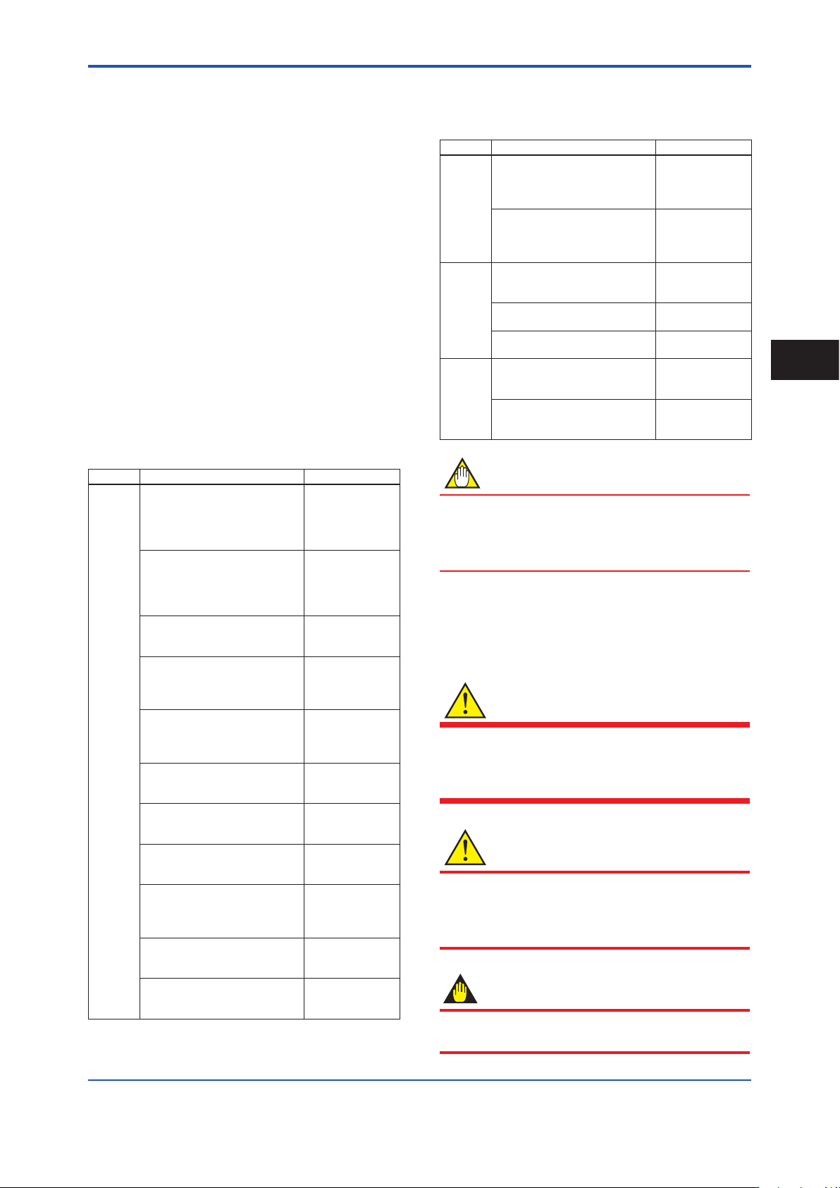
When the product is delivered, visually check that no
damage has occurred during transportation. Also check
that all owmeters mounting hardware shown below is
included.
Integral Flowmeter
Model Part name Qty.
AXW### Centering Device (*1) 1 set
Blanking Plug (*2) 0 to 2 pcs.
Remote Sensor
Model Part name Qty.
AXW### Centering Device (*1) 1 set
Remote Transmitter
Model Part name Qty.
AXW4A Mounting Bracket 1 set
Blanking Plug (*2) 0 to 2 pcs.
AXG1A Mounting Bracket 1 set
AXFA11G Mounting Bracket 1 set
*1: When the following process connection codes (wafer
type) have been selected, the centering device is
attached.
AA1, AA2, AE1, AE2, AE4, AG1, AJ1, AJ2
*2: When the following code is specied for “Power Supply”
and “Communication and I/O”, the following quantity of
blind plug is attached.
Power Supply code
-1
-2
Communication and I/O code
DA, JA, M0, F0 1 pc.
Other code 0 pc.
DA, JA 2 pcs.
M6 0 pc.
Other code 1 pc.
Qty.
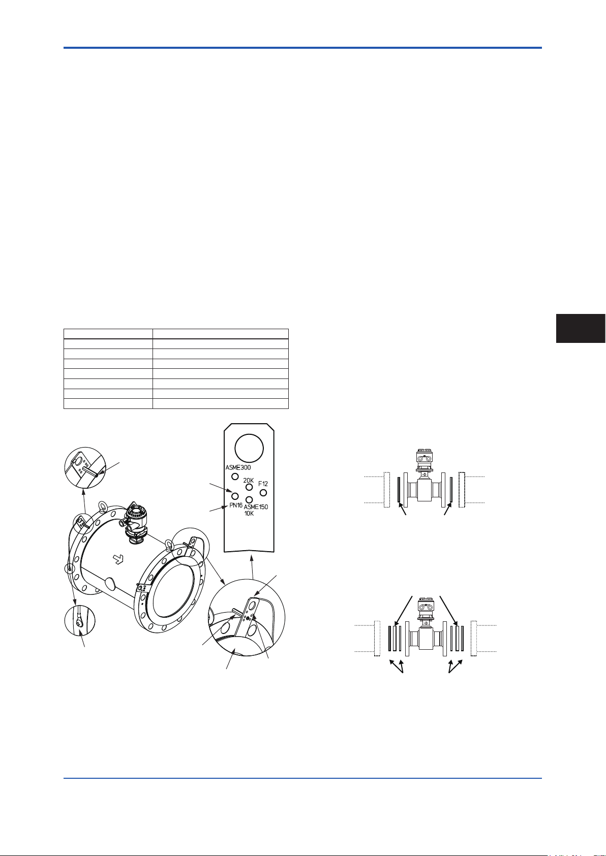
2.1 Model and Specications
Check
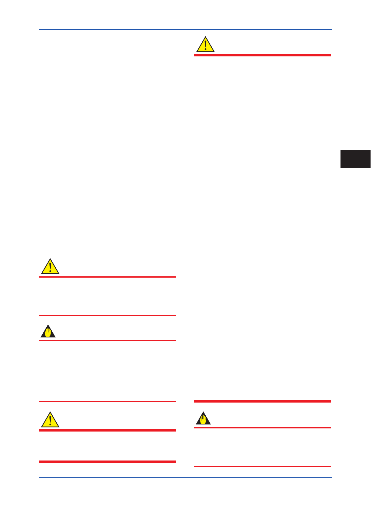
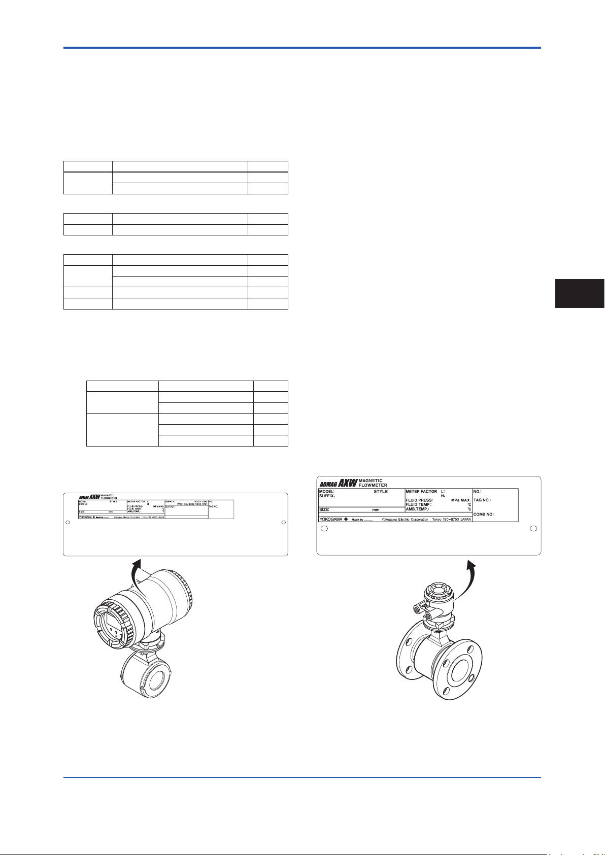
As shown in Figure 2.1 to Figure 2.5, the model, sufx
code, serial number, meter factor, uid specication, and
device information are found on the name plate located
on the outside of the housing. And, this product can check
their information from parameters. Read the user’s manual
of applicable communication type as listed in Table 1.1 for
checking device information from parameters.
When checking the matching of model and specication you
ordered, see the applicable general specications as listed in
Table 1.1.
Be sure you have the model code and serial number
available when contacting YOKOGAWA.
The model and specication described on the nameplate
are those of the state at the time of shipment.
Note: Description on the nameplate
- Made in _______: Country of origin
- COMB No.: Serial number of the combined remote
sensor or remote transmitter
2
Receiving and Storage
Figure 2.1 Name Plate (AXW Integral Flowmeter)
F0202.ai
Figure 2.2 Name Plate (AXW Remote Sensor)
IM 01E24A01-01EN
Page 9
<2. Receiving and Storage>
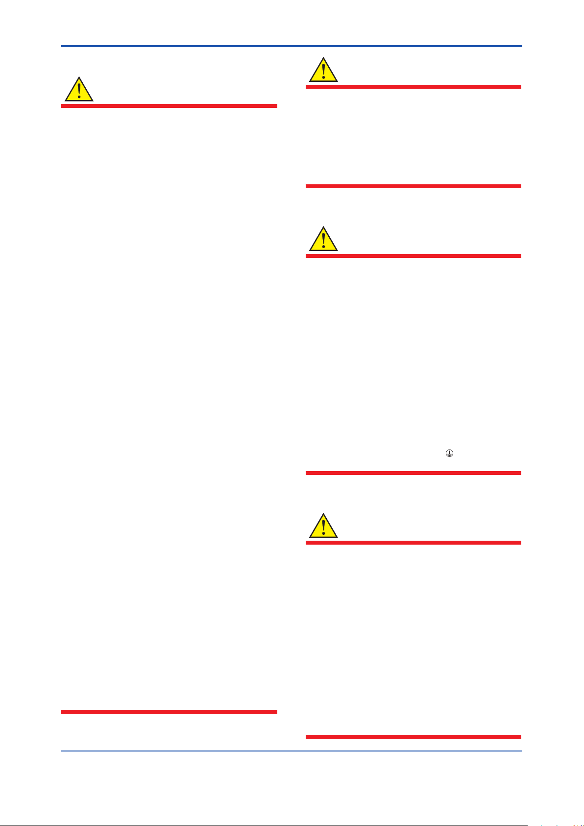
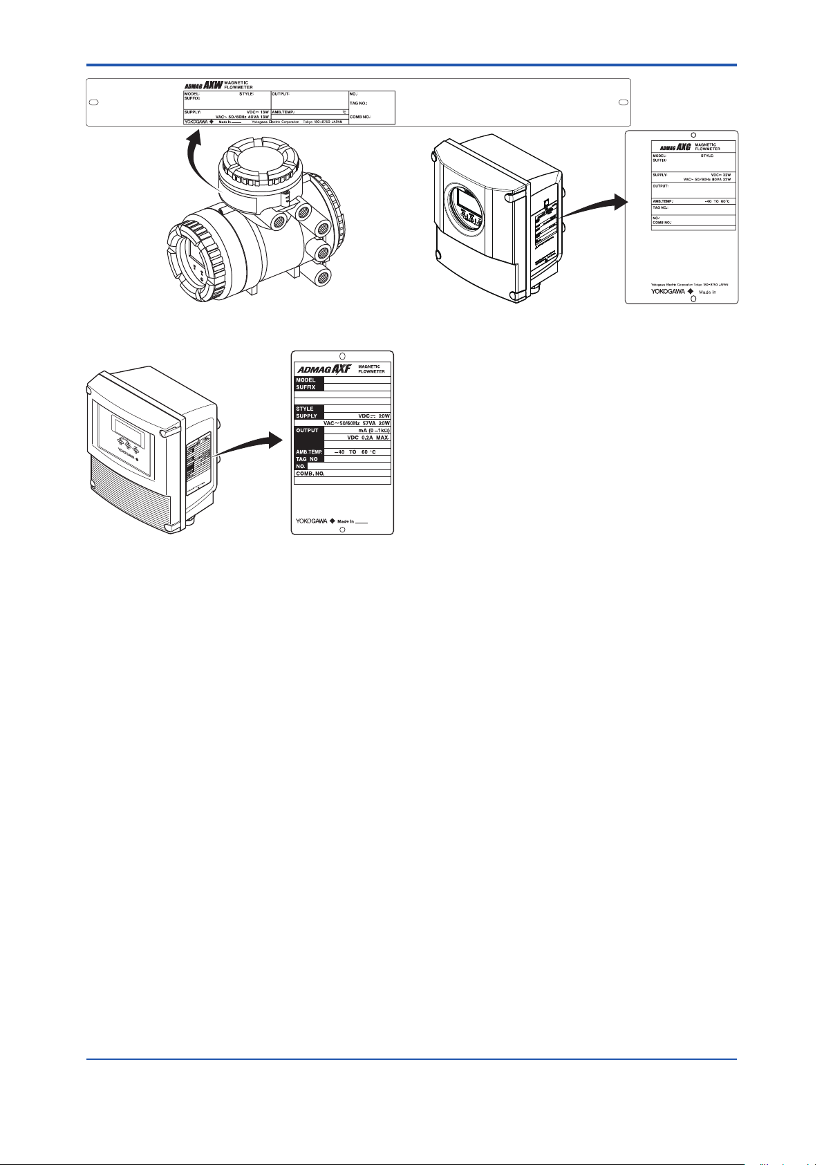
F0203.ai
F0204.ai
F0205.ai
Figure 2.3 Name Plate (AXW4A Remote Transmitter)
Figure 2.4 Name Plate (AXG1A Remote Transmitter)
8
Figure 2.5 Name Plate (AXFA11 Remote Transmitter)
2.2 Storage Precautions
If the product is to be stored for a long period of time after
delivery, observe the following points.
The product should be stored in its original packing
condition in the storage location. When the PTFE
lining is specied, the particle board is attached to the
owmeter. Keep the particle board attached until the
owmeter is install to the pipe.
Select a storage location that fulls the following
conditions:
• A place where it will not be exposed to rain or water
• A place subject to minimal vibrations or shocks
•
Temperature and humidity levels should be as follows:
Temperature: -10 to 70°C
Humidity: 5 to 80% RH (no condensation)
The preferred ambient temperature and humidity
levels are 25°C and approximately 65% RH.
If the product is transferred to the installation site and
stored without being installed, its performance may
be impaired due to the inltration of rainwater and
so forth. Be sure to install and wire the product as
soon as possible after transferring it to the installation
location.
IM 01E24A01-01EN
Page 10

<3. Installation>
3. Installation
9
WARNING
Installation of the magnetic owmeter must be
performed by expert engineer or skilled personnel.
No operator shall be permitted to perform procedures
relating to installation.
Installation Location Precautions
Select the installation location with consideration to the
following items to ensure long-term stable operation of
the product.
Ambient Temperature:
Avoid installing the product in locations with constantly
uctuating temperatures. If the location is subject to
radiant heat from the plant, provide heat insulation or
improve ventilation.
Atmospheric Condition:
Avoid installing the product in a corrosive atmosphere.
In situations where this is unavoidable, consider ways to
improve ventilation and to prevent rainwater from entering
and being retained in the conduit pipes.
Vacuum:
In the case of PTFE lining, avoid the negative pressure
inside the measuring pipe.
Vibrations or Shocks:
Avoid installing the product in a place subject to shocks or
vibrations.
3.1 Piping Design Precautions
IMPORTANT
Design piping correctly, referring to the following to
prevent damage to sensors and to assure accurate
measuring.
NOTE
This section describes the remote sensor as an
example. The same attention must be paid to the
integral owmeter.
(1) Location
IMPORTANT
Install the owmeter in a location where it is not
exposed to direct sunlight. The minimum ambient
temperature is limited by the minimum uid temperature
of the sensor (the lining). For more information, read the
applicable general specication as listed inTable 1.1.
The owmeter may be used in an ambient humidity
where the relative humidity ranges from 0 to 100%.
However, avoid long-term continuous operation at
relative humidity 95% or higher.
3
Installation
(2) Noise Avoidance
IMPORTANT
The owmeter should be installed away from
electrical motors, transformers, and other power
sources in order to avoid interference with
measurement. When installing two or more magnetic
owmeters, provide a distance of at least 5D (D is size
of model code) each other. If diameters of them are
different, let D be the larger one.
IM 01E24A01-01EN
Page 11
F0301.ai
D: Sensor Size
2D or more
F0302.ai
(Incorrect)
(Correct)
Downstream side
F0303.ai
Bypass valve
Block
valve
<3. Installation>
10
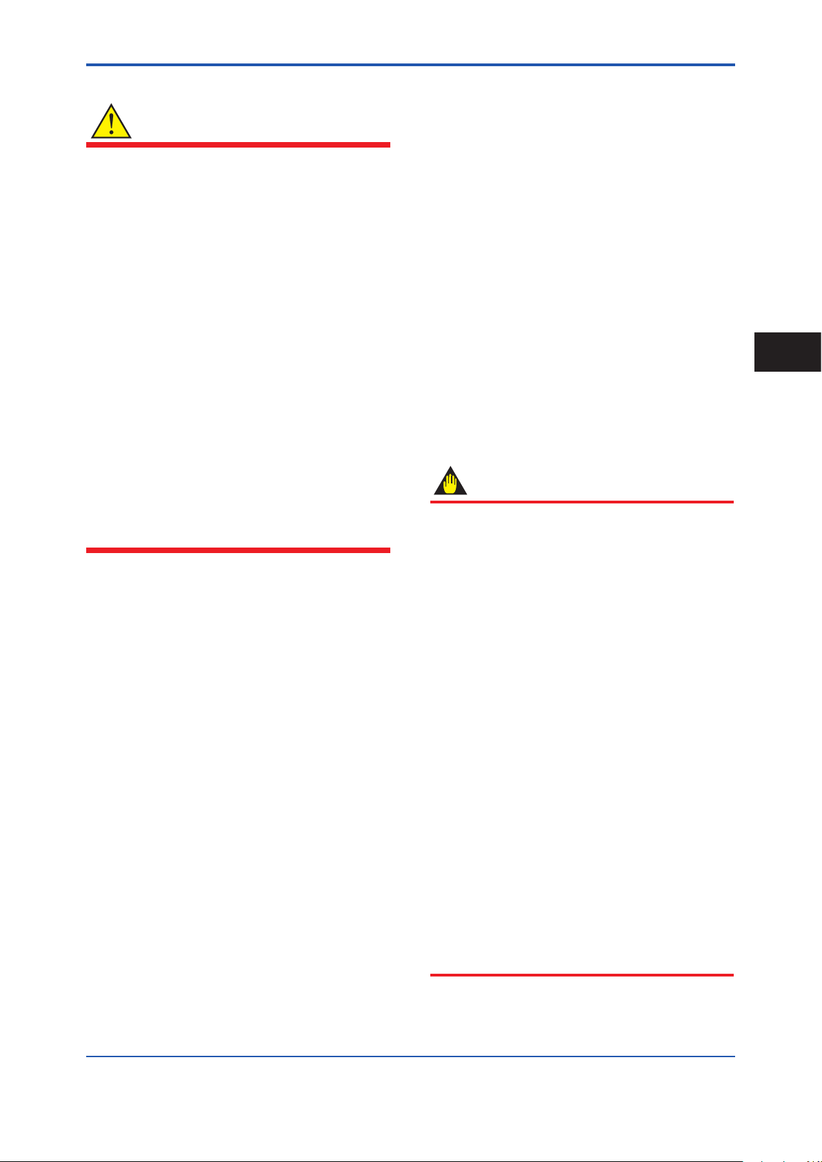
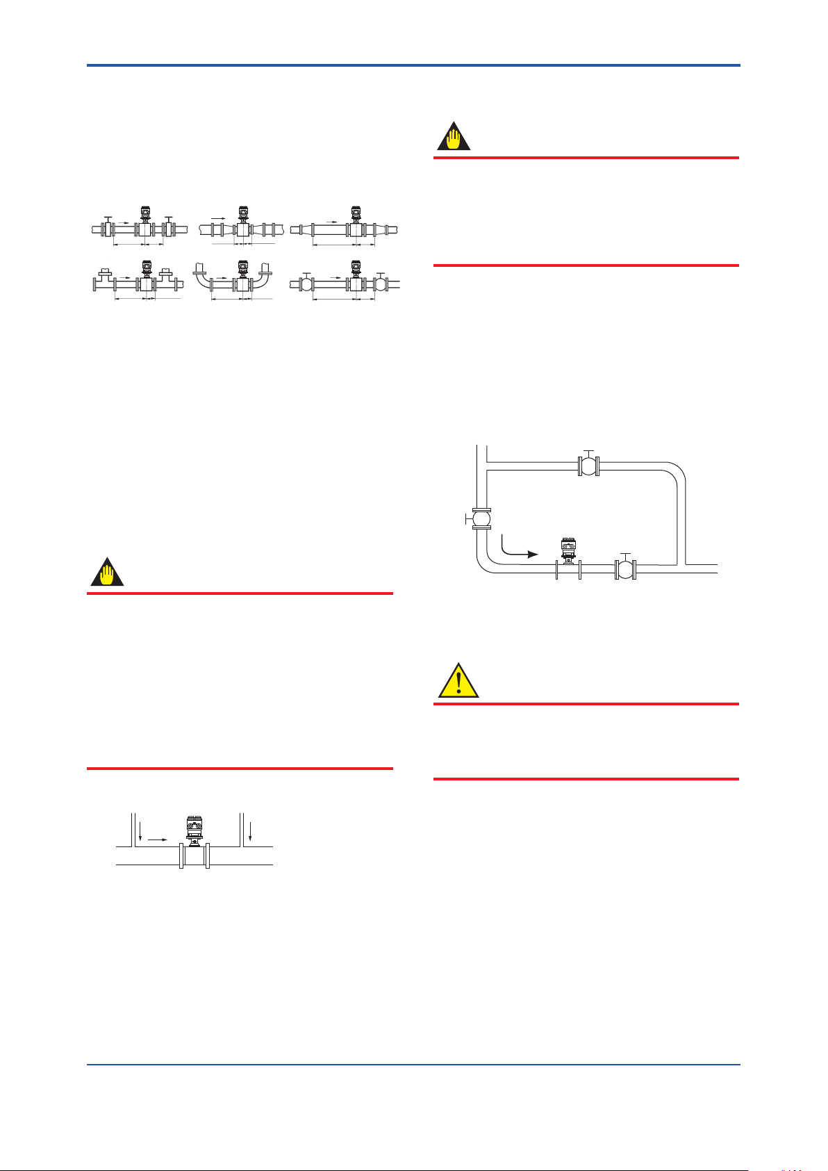
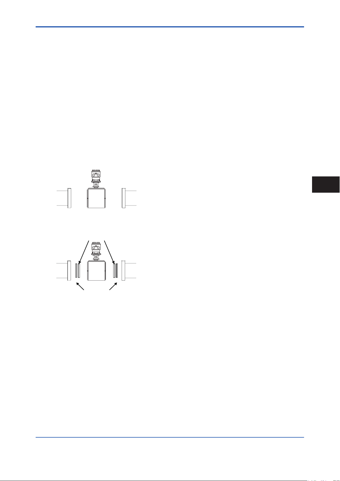
(3) Required Lengths of Straight Runs
Based on JIS B 7554 “Electromagnetic Flowmeters” and
our piping condition test data, we recommend the piping
conditions as shown in the following gures. This is not
always enough when the piping line incorporates multiple
conditions at the same time.
Gate valve
fully open
5D or more2Dor more
Tee
0 is allowable.5D or more 0 is allowable.5D or more
Figure 3.1.1 Required Lengths of Straight Runs
*1: Do not install anything in the vicinity that may interfere
with the magnetic eld, induced signal voltages, or ow
velocity distributions of the owmeter.
*2: A straight run may not be required on the downstream
side of the owmeter. However, if a downstream valve
or other tting causes irregularity or deviation in ows,
provide a straight run of 2D to 3D on the downstream side.
*3: The valves shall be mounted on the downstream side so
that deviated ows do not occur in the sensor and to avoid
startup from an empty condition.
*4: In case the piping conditions are compounded, install
on the straight pipe section where the upstream part is
sufciently rectied.
Reducer
pipe
0 is allowable. 0 is allowable.
90-degree bend
Expander
pipe
10D or more
Various valves
10D or more
2D
or more
(5) Precautions for Use of Liquid Sealing
Compounds
IMPORTANT
Care must be taken in using liquid sealing compounds
on the piping, as it may have a negative inuence on
the ow indications by owing out and covering the
surfaces of an electrode or grounding ring. In particular,
care must be taken if a liquid sealing compound is used
in the case of vertical piping.
(6) Service Area
Select locations where there is adequate space to service
installing, wiring, overhauling, etc.
(7) Bypass Line
It is recommended to install a bypass line to facilitate
maintenance and zero adjustment.
(4) Maintaining Stable Fluid Conductivity
IMPORTANT
Do not install the owmeter where uid conductivity
tends to become uneven. If chemicals are fed near
the upstream side of a magnetic owmeter, they may
affect the ow rate’s indications. To avoid this situation,
it is recommended that the chemical feed ports be
located on the downstream side of the owmeter. If
it is unavoidable that chemicals must be fed on the
upstream side, provide a sufcient length of straight
run (approximately 50D or more) to ensure the proper
mixture of uids.
Upstream side
Figure 3.1.2 Chemical Injection
Block valve
Figure 3.1.3 Bypass Line
(8) Supporting the Flowmeter
CAUTION
Do not secure the owmeter separately to prevent the
vibrations, shocks, and expansion and contraction forces
of the piping from affecting it. Fix the pipes rst, then
support the owmeter with the pipes.
IM 01E24A01-01EN
Page 12
<3. Installation>
F0304.ai
F0305.ai
F0306.ai
(Correct)
the terminal
11
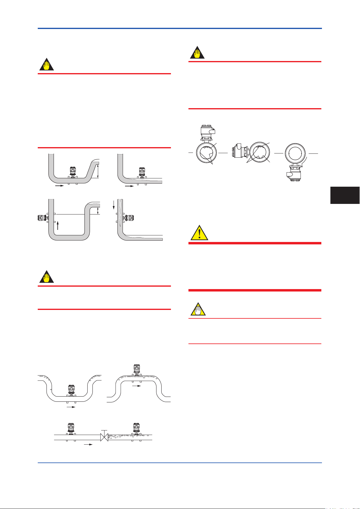
(9) Mounting Positions
Pipes must be fully lled with liquids.
IMPORTANT
It is essential that pipes remain fully lled at all times,
otherwise ow rate indications may be affected and
measurement errors may be caused.
Piping shall be designed so as to maintain the interior of
the sensor lled with uids.
Vertical mounting is effective in such cases as
when uids tend to separate or solid matter may be
precipitated. When employing vertical mounting, direct
the uids from the bottom to the top to ensure that the
pipes remain fully lled.
(Correct)
h
h>0
(Correct) (Incorrect)
h
h>0
(Incorrect)
Mounting orientation
IMPORTANT
If electrodes are perpendicular to the ground, air
bubbles near the top or precipitates at the bottom may
cause measurement errors. Ensure that the terminal
box of a remote sensor and transmitter of an integral
owmeter are mounted above the piping to prevent
water from entering them.
(Incorrect)
Air bubble
Electrode
Figure 3.1.6 Mounting Orientation
Electrode
Precipitate
(Incorrect)
Air bubble
Water can
seep into
box.
3.2 Handling Precautions
3
Installation
Figure 3.1.4 Mounting Positions
Avoid air bubbles.
IMPORTANT
If air bubbles enter a measurement pipe, ow rate
indications may be affected and measurement errors
may be caused.
In cases where uids contain air bubbles, piping must
be designed to prevent them from accumulating in the
measurement pipe of a sensor.
If a valve exists near the owmeter, try to mount the
owmeter on the valve’s upstream side in order to
prevent a possible reduction of pressure inside the pipe,
thereby avoiding the possibility of air bubbles.
(Correct)
(Incorrect)
(Correct)
(Incorrect)
WARNING
The magnetic owmeter is a heavy product.
Be careful that no damage is caused to personnel
through accidentally dropping it, or by exerting
excessive force on the magnetic owmeter. When
moving the magnetic owmeter, always use a trolley
and have at least two people carry it.
NOTE
This section describes the remote sensor as an
example. The same attention must be paid to the
integral owmeter.
3.2.1 General Precautions
(1) Precaution during Transportation
The magnetic owmeter is packed tightly. When
it is unpacked, pay attention to prevent damaging
the owmeter. To prevent accidents while it is being
transported to the installing location, transport it to the site
in its original packing.
Valve
Figure 3.1.5 Avoiding Air Bubbles
IM 01E24A01-01EN
Page 13
F0307.ai
F0308.ai
<3. Installation>
(5) Long-term Non-use
CAUTION
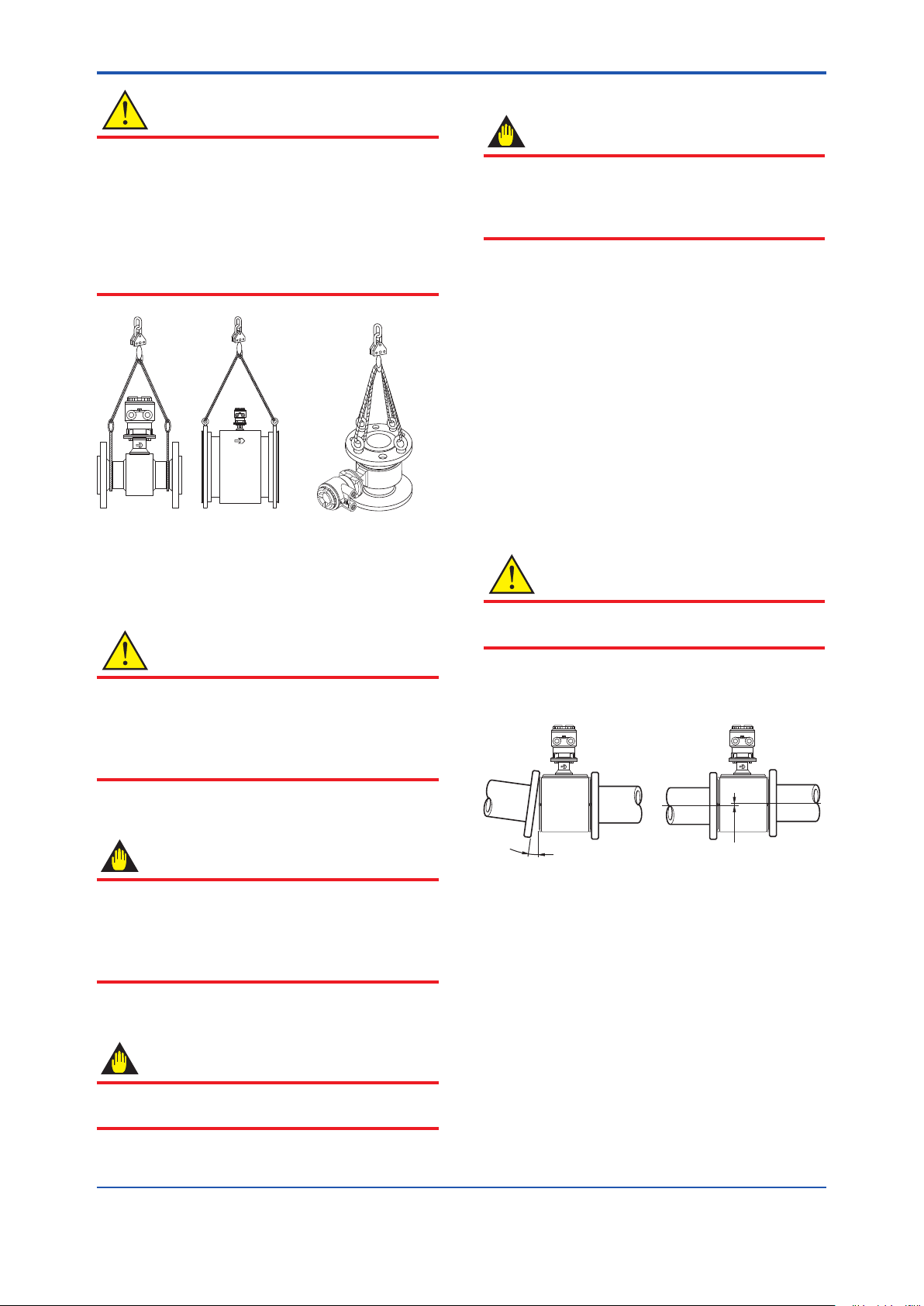
IMPORTANT
In order to lift a magnetic owmeter that is tted with
eyebolts, proceed as in Figure 3.2.1. Never lift it using
a bar passed through the sensor as this damages the
lining severely.
When lifting the magnetic owmeter in vertical position,
eyebolts (or eyenuts and bolts) are necessary. Attach
them to the ange bolt holes, and then lift the magnetic
owmeter.
Vertical positionHorizontal position
It is not desirable to leave the owmeter unused
for a long term after installation. If this situation is
unavoidable, take care of the owmeter by observing
the following.
Conrmation of sealing conditions for the
owmeter
Conrm that the terminal box screw and cable entries
are well sealed. Equip the conduit piping with drain plugs
or waterproof glands to prevent moisture or water from
penetrating into the owmeter through the conduit.
Regular inspections
Inspect the sealing conditions as mentioned above, and
the inside of the terminal box at least once a year.
Also, due to rain, etc. when it is suspected that water may
have penetrated into the inside of the owmeter, perform
supplementary inspections.
3.2.2 Flowmeter Piping
12
Figure 3.2.1 Lifting Flowmeter
(2) Avoid Shocks from Impact
CAUTION
Care should be taken not to drop the owmeter or
expose it to excessive shock. In particular, be careful
not to subject the ange surface to shock. This may
lead to lining damage which will result in inaccurate
readings.
(3) Flange Protection Covers
IMPORTANT
Keep the protective covering (i.e. the corrugated
cardboard or other cushioning material) and the
attached particle board (when PTFE lining is specied)
in place over the ange except when mounting the
owmeter to the pipe.
(4) Terminal Box Cover
IMPORTANT
CAUTION
Misaligned or slanted piping can lead to leakage and
damage to the anges.
(1) Correct any misaligned or slanted piping, and any
gaps that may exist between mounting anges before
installing the owmeter (see Figure 3.2.2).
Slanted
Figure 3.2.2 Slanted and Misaligned Flowmeter Piping
(2) Inside a newly installed pipeline, there may be some
foreign substances such as residue from welding
or wood chips. Remove them by ushing the piping
before mounting the owmeter. This prevents the
lining from being damaged, as well as the occurrence
of erroneous measured signals resulting from foreign
substances passing through the sensor during
measurement.
Misaligned
As it is possible that the insulation will deteriorate, do
not open the terminal box cover until it is time to wire it.
IM 01E24A01-01EN
Page 14
<3. Installation>
13
3.3 Integral Flowmeter and Remote Sensor Installation
WARNING
• All gaskets used for piping of magnetic owmeters
should be prepared by customers except in some
cases.
• To avoid damaging the ange surface of the sensor,
do not use spiral wound gaskets.
NOTE
• The tightening torque of gasket varies depending
on the type and the external dimensions of the lining
and the gasket. The tightening torque values and
the corresponding gasket types are indicated in the
tables of this section. The dimensions the gasket
used for piping-side ange should be decided by
referring to Subsection 3.3.3.
• For uids capable of potentially permeating PTFE
linings (such as nitric acid, hydrouoric acid, or
sodium hydrate at high temperatures), do not use
the PTFE lining type.
• The PTFE lining has a structure adhering PTFE to
the metal inner face of the sensor. When install to
the piping, be careful not to bring unequal stress or
torque to the PTFE lining.
• For the PTFE lining, it is recommended to be
installed with grounding rings, or to be installed with
short pipes at upstream and downstream sides.
3.3.1 Size 25 to 200 mm (1 to 8 in.), Wafer Type
IMPORTANT
Use bolts and nuts in compliance with the ange
ratings. When stud-type through-bolts are used, be sure
the outside diameter of the shank is smaller than that of
the thread ridge.
Be sure to choose a gasket with inner and outer
diameters that does not protrude inside the piping (read
Subsection 3.3.3). If the inner diameter of the gasket is
too large, or outer diameter of the gasket is too small,
uid leakage may result.
(1) Mounting Direction
Mount the owmeter so that the ow direction of the uid
to be measured is in line with the direction of the arrow
mark on the owmeter.
IMPORTANT
If it is impossible to match the direction of the arrow
mark, the direction of the cable entry can be changed.
Read Section 3.5.
In case the uid being measured ows against the
arrow direction, change the value from “Forward” to
“Reverse” at the parameter “Flow direct”. Read the
user's manual of the applicable communication type (for
AXW/AXW4A/AXG1A) or the hardware/software edition
(for AXFA11) as listed in Table 1.1.
Display Menu Path (AXW/AXW4A/AXG1A):
Device setup ► Detailed setup ► AUX calculation ► Flow direct
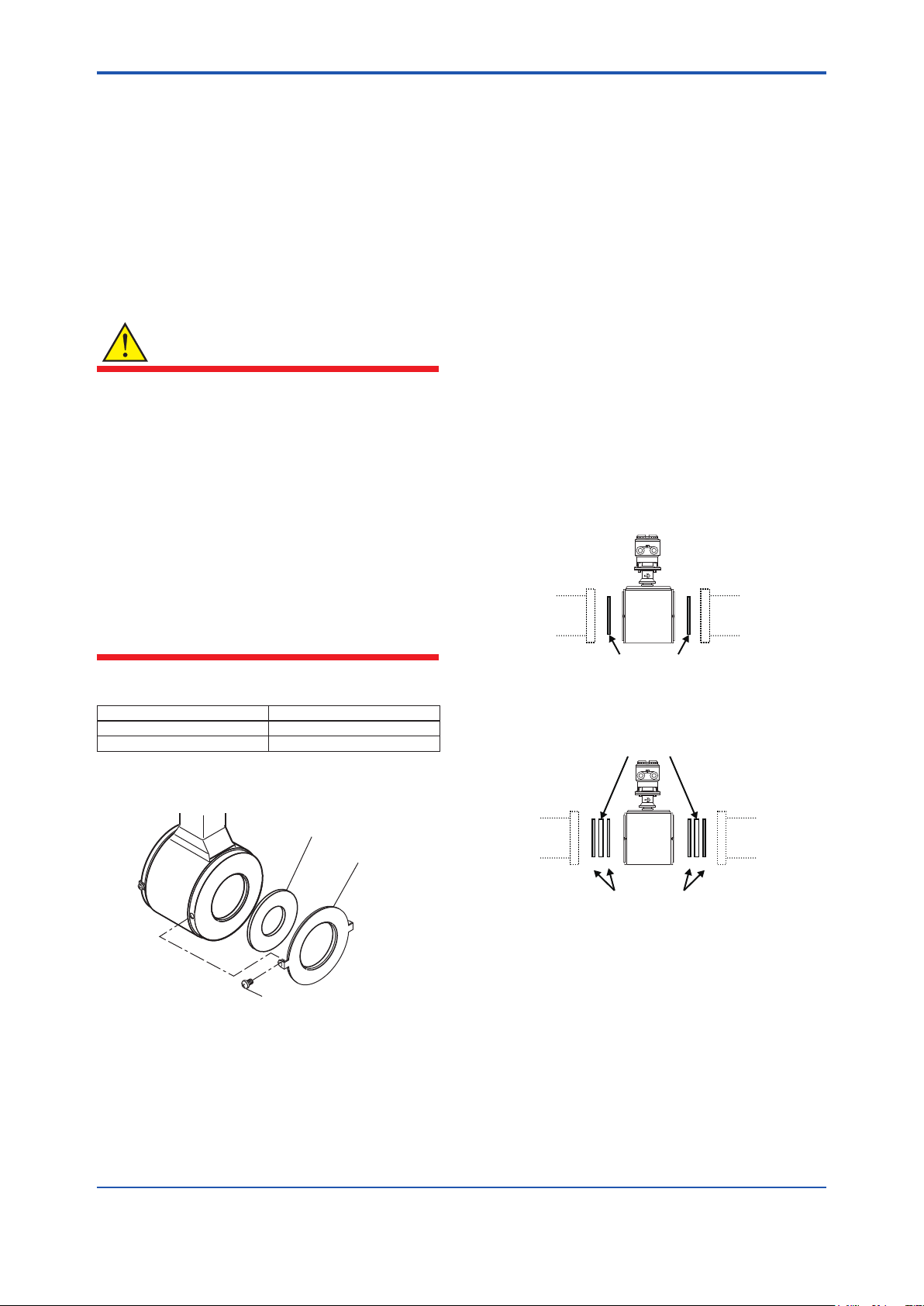
(2) Mounting Centering Devices
To maintain concentricity of the owmeter with the pipes,
install centering devices. Use the appropriate centering
devices according to the nominal diameter and the ange
ratings.
• Size: 25 to 40 mm (1 to 1.5 in.)
Pass two through-bolts through the adjacent holes of
both anges and position the owmeter so that the
Mini-anges and the centering devices come in close
contact with each other.
In case stud-type through-bolts are used, position
them in such a way that the centering devices come in
contact with the bolt threads.
Pass the other through-bolts through the other holes.
See Figure 3.3.2 for the mounting.
• Size: 50 to 200 mm (2 to 8 in.)
From the process piping side, pass two through-bolts
through the adjacent two holes (the lower two holes
for horizontal mounting) of both of the anges and the
four centering devices (two for each bolt). Be careful
to prevent the four centering devices from coming into
contact with the sensor housing.
In case stud-type through-bolts are used, position
them in such a way that the four centering devices
come in contact with the bolt threads.
Pass the other through-bolts through the other holes.
See Figure 3.3.3 for the mounting.
3
Installation
NOTE
For Size 50 to 200 mm (2 to 8 in.), the centering devices
are engraved with an identifying character. Be sure
to use the appropriate ones which meet the required
specications by referring to Table 3.3.3.
IM 01E24A01-01EN
Page 15
F0309.ai
Grounding ring
ABBA
<3. Installation>
14
(3) Installation of Gasket and Grounding
Device
The gaskets (supplied by customer) used for connection
with customer pipes differ by the presence or absence of
grounding device (grounding ring) and the specications
selected. Be sure to use the gaskets in compliance
with the ange ratings and uid specication. Install the
gaskets as the followings.
Be sure to choose gaskets with inner and outer diameters
that do not protrude inside the piping by referring to
Subsection 3.3.3.
WARNING
• All gaskets used for piping of magnetic owmeters
should be prepared by customers except in some
cases.
For the following cases, be sure to use a gasket
between the grounding ring and the lining are
section, to prevent uid leaks.
- Size 50 to 200 mm (2 to 8 in.), natural hard rubber
lining, and with grounding ring are specied.
- Grounding rings are added at a later time.
• Be sure to choose the gasket with hardness
comparable to soft rubber or the PTFE-sheathed
non-asbestos gasket, or the equivalent in hardness
gasket depending on process pressure. The
thickness of the gasket should cover the range
shown in Table 3.3.1.
Table 3.3.1 Gasket thickness
Size mm Gasket thickness (mm)
50 to 125 (2 to 5 in.) 2
150 to 200 (6 to 8 in.) 3
• Installation: Natural hard rubber lining type and
Metal pipe
When a magnetic owmeter with natural hard
rubber lining is installed to metal pipe without
lining, installation method without grounding ring is
recommended.
With grounding wire (supplied by customer), connect
between the pipe and the sensor mini-ange, or
between the transmitter and the grounding terminal of
terminal box. For grounding in detail, read Subsection
4.4.3.
For gasket A (customer pipe side), use non-asbestos
joint sheet gasket, PTFE-sheathed non-asbestos joint
sheet gasket (optional code BSF) or gasket with the
equivalent hardness.
In the case grounding ring is used, for gasket B
(sensor side), use non-asbestos joint sheet gasket,
PTFE-sheathed non-asbestos joint sheet gasket
(optional code BSF) or gasket with the equivalent
hardness.
It is recommended to use gasket with same hardness
for gasket A and B.
• Installation without grounding ring
Customer pipe
(Metal)
A A
With grounding wire, connect between the pipe and the sensor mini-flange,
or between the transmitter and the grounding terminal of terminal box.
to be supplied by customer or by specified optional code
Gasket A
Customer pipe
(Metal)
F0310.ai
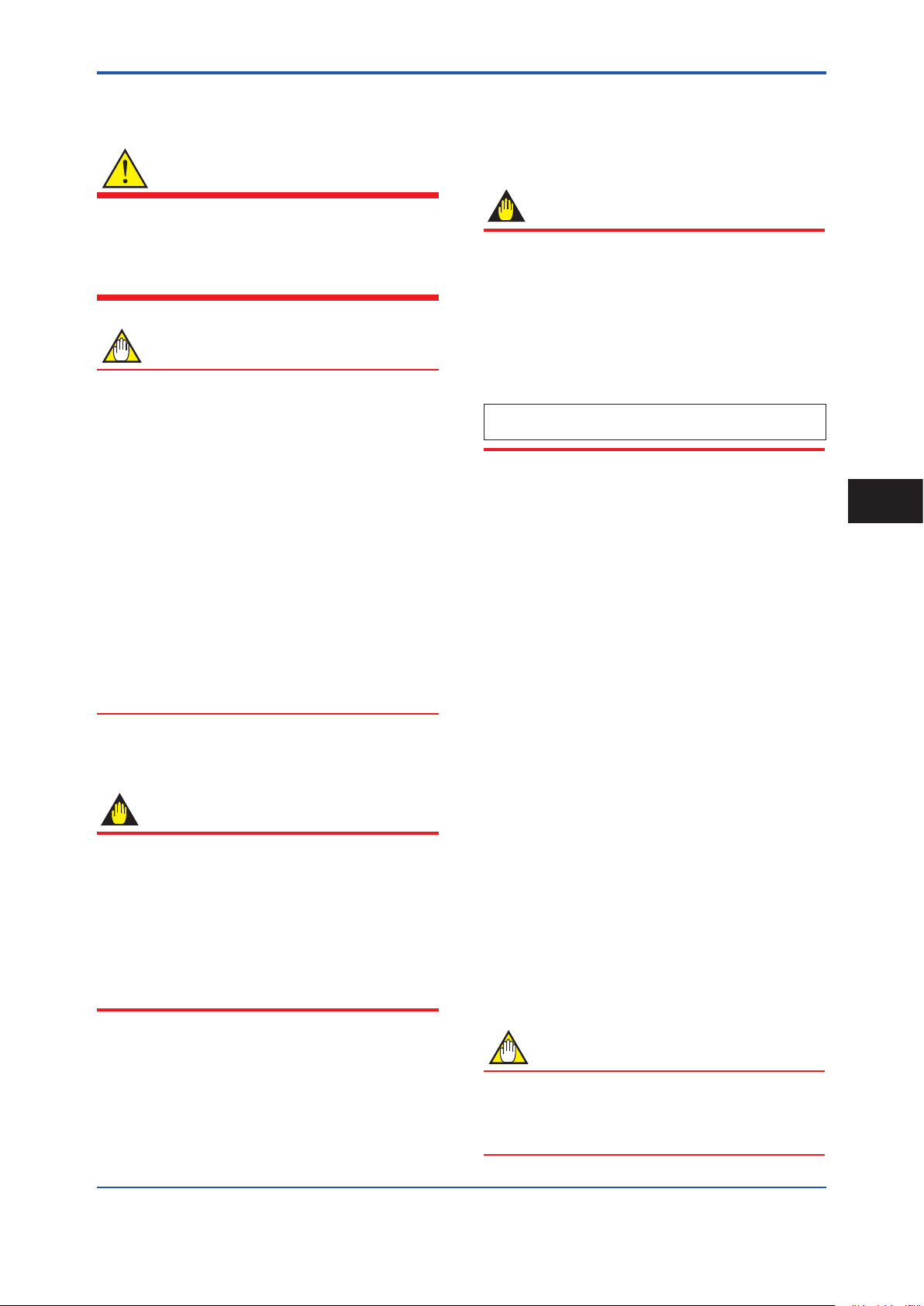
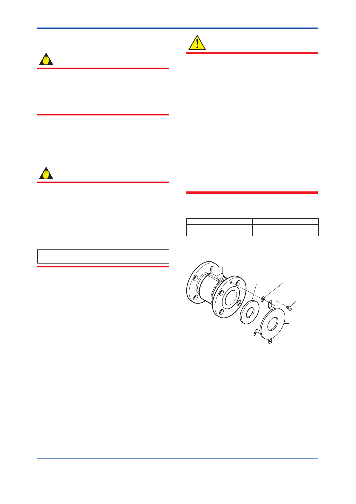
• Installation with grounding ring
Grounding ring
For size 25 to 125 mm, the grounding ring has mounting
xing brackets (See Figure 3.3.1).
Gasket
Screw
Figure 3.3.1 Mounting of grounding ring
Customer pipe
(Metal)
Gasket A
to be supplied by customer
to be supplied by customer, or to be supplied by specified optional code
Gasket B
Customer pipe
(Metal)
F0311.ai
IM 01E24A01-01EN
Page 16
<3. Installation>
A
A
• Installation: Natural soft rubber/Polyurethane
rubber lining type and Metal pipe
When a magnetic owmeter with natural soft rubber
or polyurethane rubber lining is installed to metal pipe
without lining, installation method without grounding
ring is recommended.
In the case grounding ring is not used, it is
recommended to use no gasket between the pipe
and the sensor. With grounding wire (supplied by
customer), connect between the pipe and the sensor
mini-ange, or between the transmitter and the
grounding terminal of terminal box. For grounding in
detail, read Subsection 4.4.3.
In the case grounding ring is used, for gasket A
(customer pipe side), be sure to use non-asbestos
joint sheet gasket, PTFE-sheathed non-asbestos joint
sheet gasket (optional code BSF) or gasket with the
equivalent hardness.
• Installation without grounding ring
Customer pipe
(Metal)
Customer pipe
(Metal)
15
3
Installation
With grounding wire, connect between the pipe and the sensor mini-flange,
or between the transmitter and the grounding terminal of terminal box.
F0312.ai
• Installation with grounding ring
Grounding ring
Customer pipe
(Metal)
to be supplied by customer or by specified optional code
Gasket A
Customer pipe
(Metal)
F0313.ai
(4) Tightening Nuts
Tighten the nuts according to the torque values in Table
3.3.2.
IM 01E24A01-01EN
Page 17
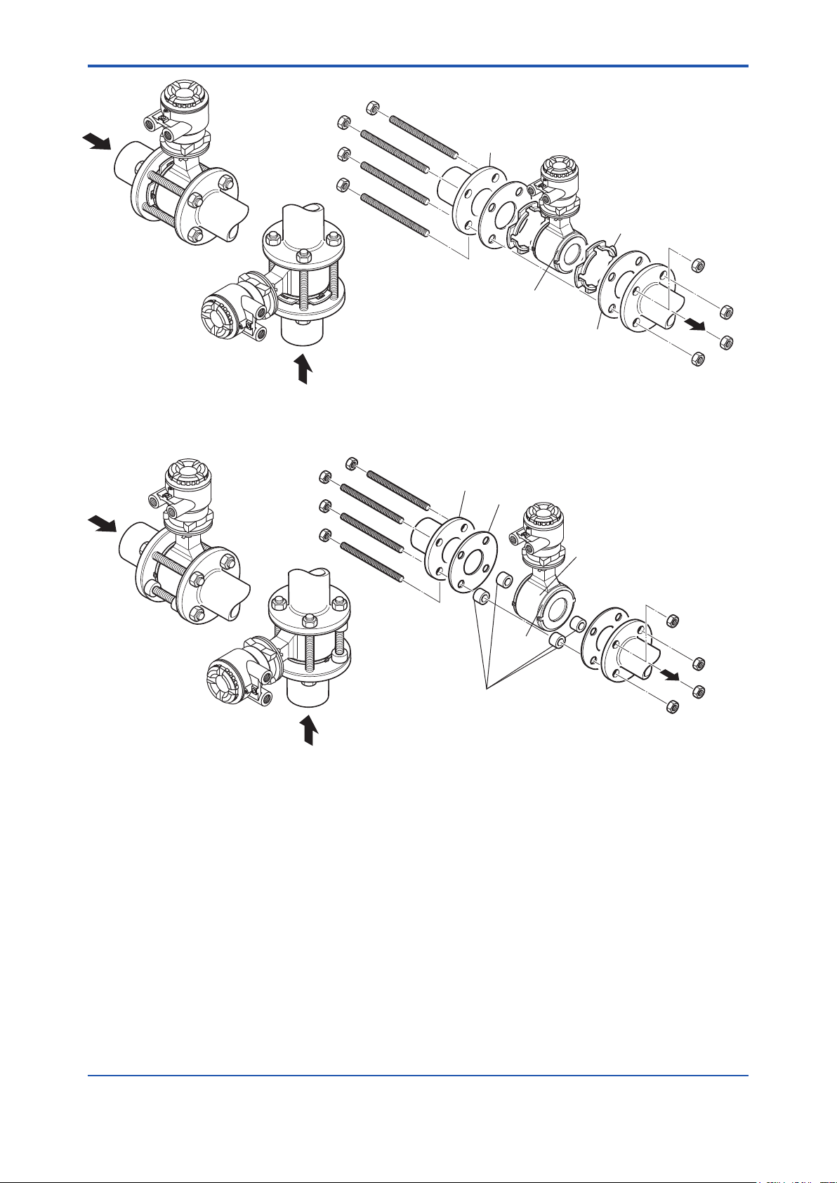
If they are provided by the user, choose nuts and
Vertical mounting
F0315.ai
*Nut
<3. Installation>
*Nut (eight units)
*Through-bolt (four units)
Piping-side flange
Horizontal mounting
Mini-flange
Figure 3.3.2 Mounting Procedure for Wafer Type (sizes: 25, 32 and 40 mm (1.0, 1.25 and 1.5 in.))
*: These items can be ordered optionally.
bolts in compliance with the flange ratings.
Centering device (two units)
*Gasket (two units)
16
F0314.ai
Horizontal mounting
*Through-bolt
Piping-side flange
*Gasket
*: These items can be ordered optionally.
If they are provided by the user, choose nuts
and bolts in compliance with the flange
ratings.
Housing
Mini
flange
Centering device (four units)
Vertical mounting
Figure 3.3.3 Mounting Procedure for Wafer Type (sizes: 50 to 200 mm (2 to 8 in.))
IM 01E24A01-01EN
Page 18
<3. Installation>
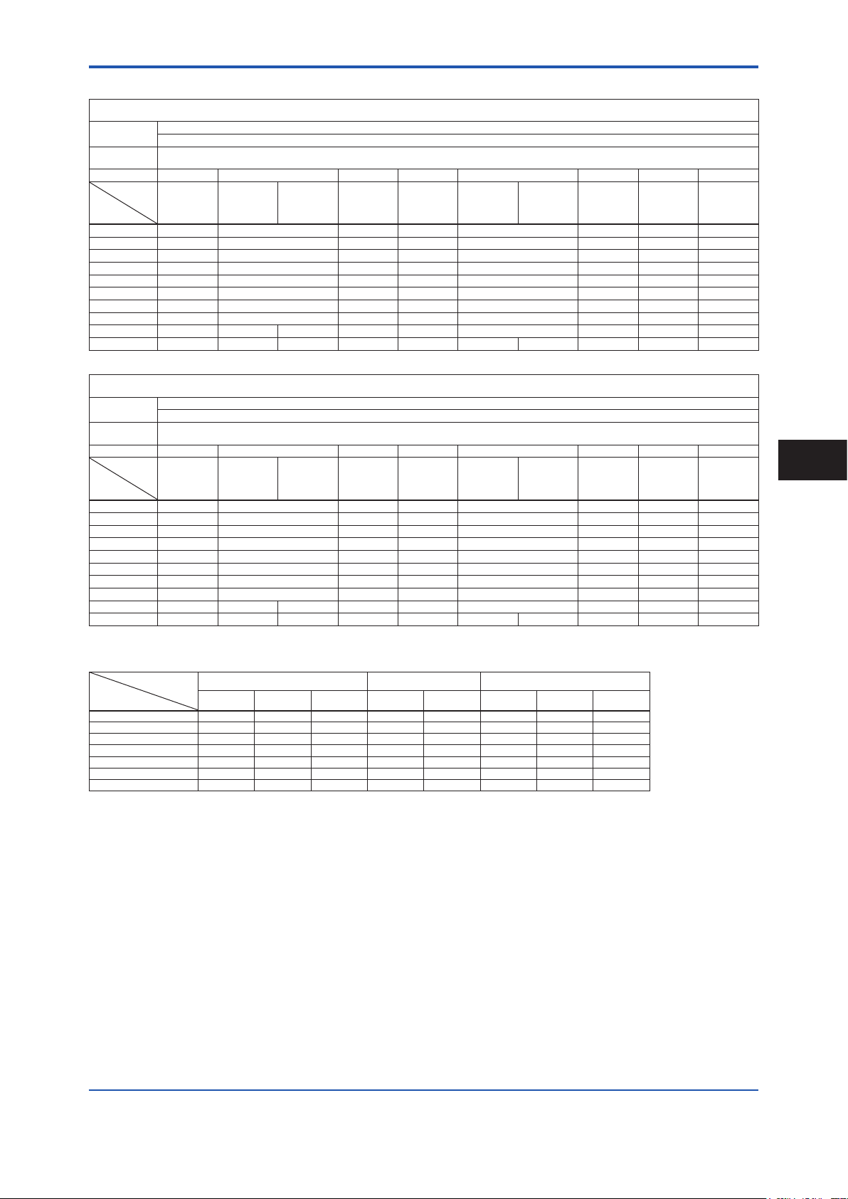
Table 3.3.2 Wafer Type Tightening Torque Values for Metal Piping
Tightening torque values for Natural Hard Rubber/Natural Soft Rubber/Polyurethane Rubber lining (N·m)
Gasket types
within sensor
Gasket types
for user’s ange
Flange Rating JIS 10K ASME Class 150 EN PN10 JIS 20K ASME Class 300 EN PN16 EN PN40 JIS F12
Thread
Standards
Size mm
25 11.2 to 18.4 8.5 to 12.6 ― 11.8 to 18.4 11.0 to 16.7 ― 8.8 to 12.7 ―
32 12.6 to 20.5 8.2 to 11.7 ― 13.5 to 20.5 10.8 to 15.5 ― 10.5 to 15.2 ―
40 19.5 to 31.3 14.3 to 20.2 ― 21.3 to 31.3 22.8 to 31.9 ― 19.0 to 26.7 ―
50 24.8 to 38.7 22.5 to 33.2 ― 13.0 to 19.3 13.9 to 19.8 ― 25.8 to 33.8 ―
65 39.2 to 59.9 36.4 to 51.9 ― 19.7 to 30.0 23.2 to 35.5 13.8 to 20.9 ― ―
80 21.6 to 33.1 37.0 to 49.2 ― 27.4 to 41.4 23.0 to 33.7 14.8 to 21.5 ― 43.7 to 66.2
100 29.2 to 42.8 24.2 to 31.6 ― 37.7 to 53.5 31.8 to 43.2 20.1 to 26.8 ― 58.9 to 85.6
125 45.9 to 65.6 34.1 to 40.5 52.9 to 71.7 37.8 to 46.2 26.1 to 32.0 ― 49.5 to 69.9
150 44.9 to 58.9 39.4 to 44.9 38.3 to 43.0 ― 33.4 to 43.0 27.3 to 32.7 32.2 to 37.6 ― 48.7 to 62.9
200 36.3 to 43.3 57.5 to 63.2 56.0 to 61.6 36.7 to 42.1 41.3 to 45.5 41.5 to 45.7 42.9 to 47.2 27.1 to 29.8 ― 45.3 to 52.0
Gasket types
within sensor
Gasket types
for user’s ange
Flange Rating JIS 10K ASME Class 150 EN PN10 JIS 20K ASME Class 300 EN PN16 EN PN40 JIS F12
Thread
Standards
Size in.
1.0 99.1 to 162.9 75.2 to 111.5 ― 104.4 to 162.9 97.4 to 147.8 ― 77.9 to 112.4 ―
1.25 111.5 to 181.4 72.6 to 103.6 ― 119.5 to 181.4 95.6 to 137.2 ― 92.9 to 134.5 ―
1.5 172.6 to 277.0 126.6 to 178.8 ― 188.5 to 277.0 201.8 to 282.3 ― 168.2 to 236.3 ―
2.0 219.5 to 342.5 199.1 to 293.8 ― 115.1 to 170.8 123.0 to 175.2 ― 228.3 to 299.2 ―
2.5 346.9 to 530.2 322.2 to 459.4 ― 174.4 to 265.5 205.3 to 314.2 122.1 to 185.0 ― ―
3.0 191.2 to 293.0 327.5 to 435.5 ― 242.5 to 366.4 203.6 to 298.3 131.0 to 190.3 ― 386.8 to 585.9
4.0 258.4 to 378.8 214.2 to 279.7 ― 333.7 to 473.5 281.5 to 382.4 177.9 to 237.2 ― 521.3 to 757.6
5.0 406.2 to 580.6 301.8 to 358.5 468.2 to 634.6 334.6 to 408.9 231.0 to 283.2 ― 438.1 to 618.7
6.0 397.4 to 521.3 348.7 to 397.4 339.0 to 380.6 ― 295.6 to 380.6 241.6 to 289.4 285.0 to 332.8 ― 431.0 to 556.7
8.0 321.3 to 383.2 508.9 to 559.4 495.6 to 545.2 324.8 to 372.6 365.5 to 402.7 367.3 to 404.5 379.7 to 417.8 239.9 to 263.8 ― 400.9 to 460.2
Metric
screw
Metric
screw
Natural Hard Rubber lining: Non-asbestos gasket, PTFE-sheathed non-asbestos gasket, or the equivalent in hardness
Non-asbestos gasket, PTFE-sheathed non-asbestos gasket (Optional code BSF), or the equivalent in hardness
Metric
screw
Tightening torque values for Natural Hard Rubber/Natural Soft Rubber/Polyurethane Rubber lining (in.·lbf)
Natural Hard Rubber lining: Non-asbestos gasket, PTFE-sheathed non-asbestos gasket, or the equivalent in hardness
Non-asbestos gasket, PTFE-sheathed non-asbestos gasket (Optional code BSF), or the equivalent in hardness
Metric
screw
Natural Soft Rubber/Polyurethane Rubber lining: No gasket (Standard)
Unied
screw
Unied
screw
Metric
screw
Natural Soft Rubber/Polyurethane Rubber lining: No gasket (Standard)
Metric
screw
Metric
screw
Metric
screw
Metric
screw
Metric
screw
Unied
screw
Unied
screw
Metric
screw
Metric
screw
Metric
screw
Metric
screw
Metric
screw
Metric
screw
17
3
Installation
Table 3.3.3 Centering Device Identication (Natural Hard Rubber/Natural Soft Rubber/Polyurethane Rubber lining)
Size
mm (inch)
Flange Rating
10K 20K F12 Class 150 Class 300 PN10 PN16 PN40
50 (2.0) B B — B F — — F
65 (2.5) B B — B G — F —
80 (3.0) B F H F C — G —
100 (4.0) B F H C H — F —
125 (5.0) B C C G D — F —
150 (6.0) C D D C E — C —
200 (8.0) C D D D E C C —
JIS ASME EN
*: Each centering device is engraved with a character as identication.
IM 01E24A01-01EN
Page 19
F0316.ai
<3. Installation>
3.3.2 Size 25 to 400 mm (1 to 16 in.), Flange Type
WARNING
18
IMPORTANT
Use bolts and nuts in compliance with the ange
ratings. Be sure to choose a gasket with inner and outer
diameters that does not protrude inside the piping (read
Subsection 3.3.3). If the inner diameter of the gasket is
too large, or outer diameter of the gasket is too small,
uid leakage may result.
(1) Mounting Direction
Mount the owmeter so that the ow direction of the uid
to be measured is in line with the direction of the arrow
mark on the owmeter.
IMPORTANT
If it is impossible to match the direction of the arrow
mark, the direction of the cable entry can be changed.
Read Section 3.5.
In case the uid being measured ows against the
arrow direction, change the value from “Forward” to
“Reverse” at the parameter “Flow direct”. Read the
user's manual of the applicable communication type (for
AXW/AXW4A/AXG1A) or the hardware/software edition
(for AXFA11) as listed in Table 1.1.
Display Menu Path (AXW/AXW4A/AXG1A):
Device setup ► Detailed setup ► AUX calculation ► Flow direct
• All gaskets used for piping of magnetic owmeters
should be prepared by customers except in some
cases.
• For the following cases, be sure to use a gasket
between the grounding ring and the lining are
section, to prevent uid leaks.
- Size 50 to 400 mm (2 to 16 in.), natural hard
rubber lining, and with grounding ring are
specied.
- Size 150 to 400 mm (6 to 16 in.), and PTFE lining,
and with grounding ring are specied.
- Above two conditions, grounding rings are added
at a later time.
• Be sure to choose the gasket with hardness
comparable to soft rubber or the PTFE-sheathed
non-asbestos gasket, or the equivalent in
hardness gasket depending on process pressure.
The thickness of the gasket should cover the
range shown in Table 3.3.4.
Table 3.3.4 Gasket thickness
Size mm Gasket thickness (mm)
50 to 125 (2 to 5 in.) 2
150 to 400 (6 to 16 in.) 3 to 5
For size 25 to 125 mm, the grounding ring has mounting
xing brackets (See Figure 3.3.4).
(2) Installation of Gasket and Grounding
Device
The gaskets (supplied by customer) used for connection
with customer pipes differ by the presence or absence
of grounding device (grounding ring) and the specied
specications. Be sure to use the gaskets in compliance
with the ange ratings and uid specication. Install the
gaskets as the followings.
Be sure to choose gaskets with inner and outer diameters
that do not protrude inside the piping by referring to
Subsection 3.3.3.
Washer
Gasket
Figure 3.3.4 Mounting of grounding ring
(PTFE lining type)
Screw
Grounding
ring
Size 150 to 400 mm (6 to 16 in.), PTFE or natural hard
rubber lining, and with grounding ring are specied, the
grounding ring has handles (See Figure 3.3.5).
Handles of the grounding ring have some holes which
correspond to outer diameter of each ange type.
There are printings near each hole. The printings
show types of ange. See the Table 3.3.5. Conrm the
centering pin is xed to the hole corresponding to ange
or x the centering pin to the correct hole.
IM 01E24A01-01EN
Page 20
<3. Installation>
ABA
B
19
Size 150 to 200 mm (6 to 8 in.) is specied, hang the
grounding rings with their ange type printings outer side
of the magnetic owmeter.
Set the angle of both handles symmetrically to be top.
If there are any bolt-holes under the handles, turn the
grounding rings clockwise in order to locate handles
between bolt-holes. Center the grounding ring to the
center of the magnetic owmeter.
Size 250 to 400 mm (10 to 16 in.) is specied, hang the
grounding rings with their ange type printings outer side
of the magnetic owmeter.
Set the angle of both handles symmetrically to be 45
degree from top. If there are any bolt-holes under the
handles, turn the grounding rings clockwise in order to
locate handles between bolt-holes. Center the grounding
ring to the center of the magnetic owmeter.
Connect the wire from the grounding ring to the screw of
the magnetic owmeter’s ange and x the wire by the
screw. This procedure must be done for the both sides of
the magnetic owmeter.
Table 3.3.5 Printing and Flange Rating
Printing Flange Type
ASME 150 ASME Class 150
ASME 300 ASME Class 300
PN10 EN PN10
PN16 EN PN16
10K JIS 10K
20K JIS 20K
F12 JIS F12
• Installation: PTFE/Natural hard rubber lining type
and Metal pipe
When a magnetic owmeter with PTFE or natural
hard rubber lining is installed to metal pipe without
lining, the installation method without grounding ring
is recommended.
Size 25 to 125 mm (1 to 5 in.), PTFE lining,
and without grounding ring are specied, it is
recommended to use no gasket between the pipe
and the sensor. With grounding wire (supplied by
customer), connect between the pipe and the sensor
ange, or between the transmitter and the grounding
terminal of terminal box. For grounding in detail, read
Subsection 4.4.3.
Size 150 to 400 mm (6 to 16 in.), PTFE or natural
hard rubber lining, and without grounding ring are
specied, use the gasket A (customer pipe side) for
connection with customer pipes. With grounding wire
(supplied by customer), connect between the pipe
and the sensor ange, or between the transmitter and
the grounding terminal of terminal box. For grounding
in detail, read Subsection 4.4.3.
For gasket A (customer pipe side), use non-asbestos
joint sheet gasket, PTFE-sheathed non-asbestos joint
sheet gasket or gasket with the equivalent hardness.
For gasket B (sensor side), use non-asbestos joint
sheet gasket, PTFE-sheathed non-asbestos joint
sheet gasket or gasket with the equivalent hardness.
It is recommended to use gasket with same hardness
for gasket A and B.
3
Installation
Centering Pin
Hole
Printing of
Flange Type
Screw: Connect
the wire from the
grounding ring or
the customer’s
pipe
Centering Pin
Grounding Ring
Printed
Surface
Note: Size 150 to 200 mm (6 to 8 in.), PTFE lining, and with
grounding ring are specied, the handle is one.
Figure 3.3.5 Mounting of grounding ring
Handle
F0317.ai
• Installation without grounding ring
Customer pipe
(Metal)
A A
With grounding wire, connect between the pipe and the sensor flange,
or between the transmitter and the grounding terminal of terminal box.
(Size 25 to 125 mm (1 to 5 in.), and PTFE lining are specified, Gasket
Gasket A
to be supplied by customer
A is unnecessary.)
Customer pipe
(Metal)
F0318.ai
• Installation with grounding ring
Grounding ring
Customer pipe
(Metal)
Gasket A
to be supplied by customer
Gasket B
to be supplied by customer
Customer pipe
(Metal)
F0319.ai
IM 01E24A01-01EN
Page 21
A
A
A
B
A
B
F0323.ai
*: These items must be
provided by the user. Choose
<3. Installation>
20
• Installation: Natural soft rubber/Polyurethane
rubber lining type and Metal pipe
When a magnetic owmeter with natural soft rubber
or polyurethane rubber lining is installed to metal
pipe without lining, the installation method without
grounding ring is recommended.
In the case grounding ring is not used, with grounding
wire (supplied by customer), connect between the
pipe and the sensor ange, or between the transmitter
and the grounding terminal of terminal box. For
grounding in detail, read Subsection 4.4.3.
For gasket A (customer pipe side), use non-asbestos
joint sheet gasket, PTFE-sheathed non-asbestos joint
sheet gasket or gasket with the equivalent hardness.
• Installation without grounding ring
Customer pipe
(Metal)
With grounding wire, connect between the pipe and the sensor flange,
or between the transmitter and the grounding terminal of terminal box.
•
Installation with grounding ring
Grounding ring
Customer pipe
(Metal)
F0320.ai
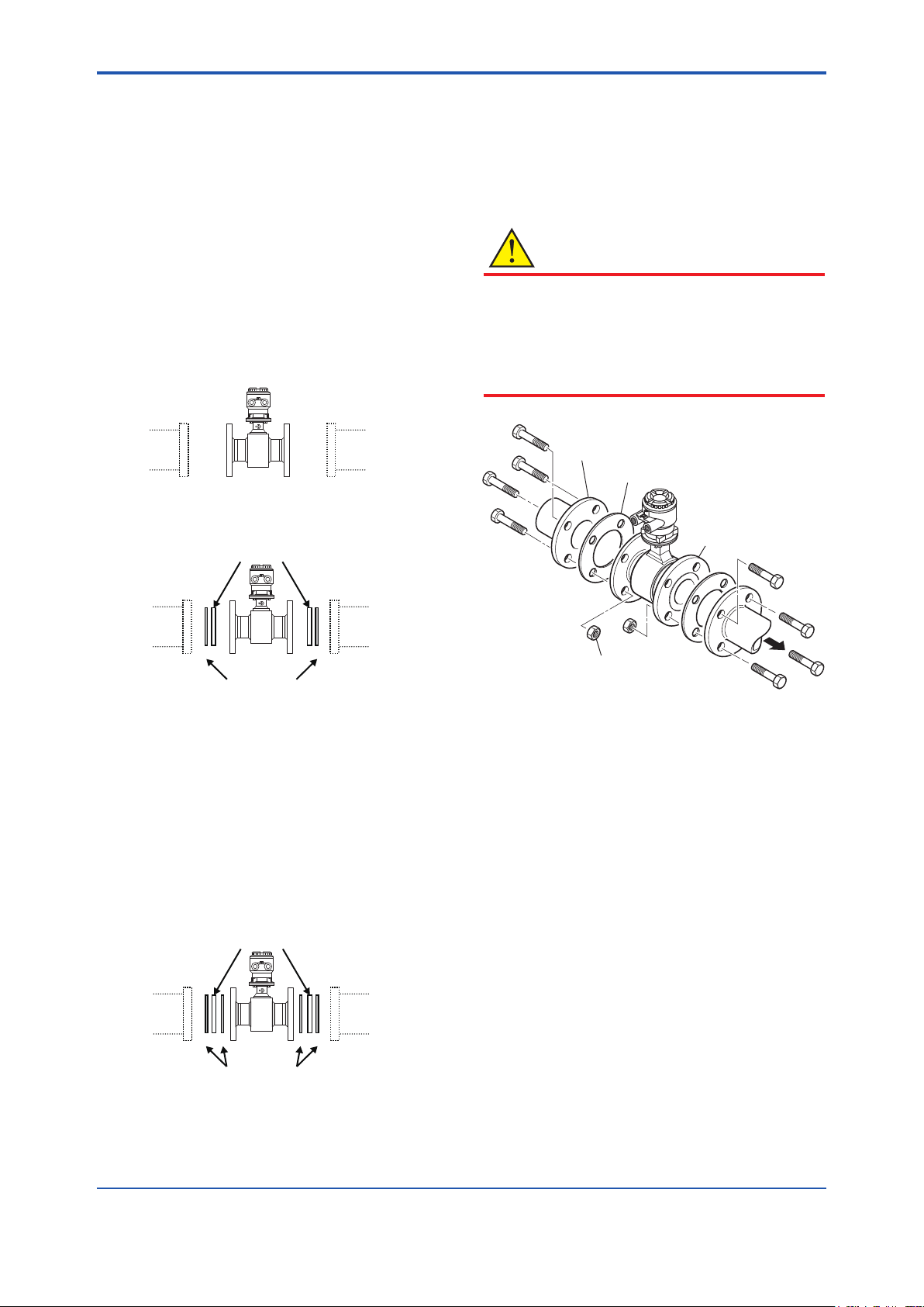
(3) Tightening Nuts
Tighten the nuts according to the torque values for the
metal piping in Table 3.3.6. For plastic piping, using the
gaskets for plastic piping (optional code GA, GC or GD),
tighten the nuts according to the torque values in Table
3.3.7.
CAUTION
For a owmeter with uorocarbon PTFE lining, it is
possible that the nuts may loosen as time passes,
so tighten them regularly. Be sure to tighten the nuts
according to the prescribed torque values. Tighten them
diagonally with the same torque values, step by step up
to the prescribed torque value.
*Piping-side flange
*Gasket (two units)
*Bolt
nuts and bolts in compliance
with the flange ratings.
When the PTFE lining is
specified, the particle board
is attached to the flowmeter.
Do not reuse nuts and bolts
used to attach the particle
board.
Flowmeter-side flange
Customer pipe
(Metal)
Gasket A
to be supplied by customer
Customer pipe
(Metal)
F0321.ai
• Installation: PTFE lining type and Plastic pipe
When a magnetic owmeter with PTFE lining is
installed to plastic pipe, be sure to use grounding
rings.
For gasket A (customer pipe side), use uororubber
gasket, chloroprene rubber gasket or gasket with the
equivalent hardness.
For gasket B (sensor side), use uororubber gasket
(optional code GA, GC or GD) or gasket with the
equivalent hardness.
It is recommended to use gasket with same hardness
for gasket A and B.
Grounding ring
Customer pipe
(Plastic)
to be supplied by customer or by specified optional code
Gasket A
to be supplied by customer
Gasket B
Customer pipe
(Plastic)
F0322.ai
*Nut
Figure 3.3.6 Mounting Procedure for Flange Type
(sizes: 25 to 400 mm (1 to 16 in.))
IM 01E24A01-01EN
Page 22

<3. Installation>
Table 3.3.6 Flange Type Tightening Torque Values for Metal Piping
Gasket types
within sensor
Gasket types
for user’s ange
Flange Rating JIS 10K ASME Class 150 EN PN10 JIS 20K ASME Class 300 EN PN16 EN PN40 JIS F12
Thread
Standards
Size mm
25 10.3 to 17.2 8.5 to 13.1
32 15.5 to 25.7 11.6 to 17.7
40 18.0 to 29.7 14.3 to 21.4
50 27.0 to 43.8 12.9 to 21.0
65 41.6 to 66.6 19.7 to 31.4
80 22.2 to 36.0 19.7 to 30.6
100 28.9 to 45.8 27.0 to 40.5
125 47.1 to 74.4 39.5 to 57.1
150 70.4 to 108.0 41.4 to 59.8
200 55.8 to 84.1 54.9 to 74.1
250 95.0 to 139.9 66.3 to 91.8 68.2 to 100.8 140.3 to 193.9 100.3 to 131.0 84.6 to 120.9
300 76.8 to 111.6 75.1 to 97.5 72.4 to 102.3 143.8 to 195.8 158.8 to 201.5 66.0 to 92.1
350 111.9 to 167.8 88.2 to 126.1 82.4 to 117.7
400 169.6 to 251.4 126.4 to 176.9 141.1 to 203.4
Metric
screw
Tightening torque values for PTFE/Natural Hard Rubber/Natural Soft Rubber lining (N·m)
PTFE/Natural Hard Rubber lining: Non-asbestos gasket, PTFE-sheathed non-asbestos gasket, or the equivalent in hardness
Non-asbestos gasket, PTFE-sheathed non-asbestos gasket, or the equivalent in hardness
Metric
screw
Unied
screw
Natural Soft Rubber lining: No gasket (Standard)
Metric
screw
―
―
―
―
―
―
―
―
―
69.1 to 103.2
Metric
screw
10.6 to 17.2 11.1 to 17.8
16.1 to 25.7 15.0 to 23.3
19.0 to 29.7 22.3 to 33.7
13.8 to 21.9 13.7 to 21.0
20.7 to 33.3 24.2 to 37.5
28.0 to 45.1 24.1 to 36.6 17.3 to 27.5
37.9 to 59.1 33.2 to 48.4 23.2 to 35.7
53.2 to 81.4 41.2 to 57.1 31.0 to 45.9
60.8 to 92.7 51.6 to 72.1 58.0 to 86.4
86.4 to 124.4 85.5 to 117.2 47.3 to 68.8
― ― ― ―
― ― ― ―
Metric
screw
Unied
screw
Metric
screw
―
―
―
―
16.3 to 26.3 ― ―
Metric
screw
8.4 to 13.1
14.7 to 23.0
18.4 to 28.2
29.1 to 42.7
― 45.3 to 72.1
―
―
―
―
70.1 to 100.9
―
134.0 to 192.0
―
117.3 to 163.3
184.7 to 268.4
210.9 to 305.4
Metric
screw
61.0 to 94.6
51.7 to 79.4
77.1 to 115.2
21
―
―
―
―
Gasket types
within sensor
Gasket types
for user’s ange
Flange Rating JIS 10K ASME Class 150 EN PN10 JIS 20K ASME Class 300 EN PN16 EN PN40 JIS F12
Thread
Standards
Size in.
1.0 91.2 to 152.2 75.2 to 115.9
1.25 137.2 to 227.5 102.7 to 156.7
1.5 159.3 to 262.9 126.6 to 189.4
2.0 239.0 to 387.7 114.2 to 185.9
2.5 368.2 to 589.5 174.4 to 277.9
3.0 196.5 to 318.6 174.4 to 270.8
4.0 255.8 to 405.4 239.0 to 358.5
5.0 416.9 to 658.5 349.6 to 505.4
6.0 623.1 to 955.9 366.4 to 529.3
8.0 493.9 to 744.3 485.9 to 655.8
10 840.8 to 1238.2 586.8 to 812.5 603.6 to 892.2
12 679.7 to 987.7 664.7 to 862.9 640.8 to 905.4
14 990.4 to 1485.2 780.6 to 1116.1 729.3 to 1041.7
16
Metric
screw
1501.1 to 2225.1
Tightening torque values for PTFE/Natural Hard Rubber/Natural Soft Rubber lining (in.·lbf)
PTFE/Natural Hard Rubber lining: Non-asbestos gasket, PTFE-sheathed non-asbestos gasket, or the equivalent in hardness
Non-asbestos gasket, PTFE-sheathed non-asbestos gasket, or the equivalent in hardness
Metric
screw
1118.7 to 1565.7
Unied
screw
Natural Soft Rubber lining: No gasket (Standard)
Metric
screw
―
―
―
―
―
―
―
―
―
611.6 to 913.4
1248.8 to 1800.2
Metric
screw
93.8 to 152.2 98.2 to 157.5
142.5 to 227.5 132.8 to 206.2
168.2 to 262.9 197.4 to 298.3
122.1 to 193.8 121.3 to 185.9
183.2 to 294.7 214.2 to 331.9
247.8 to 399.2 213.3 to 323.9 153.1 to 243.4
335.4 to 523.1 293.8 to 428.4 205.3 to 316.0
470.9 to 720.5 364.7 to 505.4 274.4 to 406.2
538.1 to 820.5 456.7 to 638.1 513.3 to 764.7
764.7 to 1101.0 756.7 to 1037.3 418.6 to 608.9
1241.8 to 1716.2
1272.7 to 1733.0
― ― ― ―
― ― ― ―
Metric
screw
887.7 to 1159.4 748.8 to 1070.1
1405.5 to 1783.4 584.1 to 815.2
Unied
screw
Metric
screw
―
―
―
―
144.3 to 232.8 ― ―
Metric
screw
74.3 to 115.9
130.1 to 203.6
162.9 to 249.6
257.6 to 377.9
― 400.9 to 638.1
―
―
―
682.4 to 1019.6
―
―
1186.0 to 1699.3
―
1038.2 to 1445.3
1634.7 to 2375.5
1866.6 to 2703.0
Metric
screw
539.9 to 837.3
457.6 to 702.7
620.4 to 893.0
3
Installation
―
―
―
―
IM 01E24A01-01EN
Page 23

<3. Installation>
22
Gasket types
within sensor
Gasket types
for user’s ange
Flange Rating JIS 10K ASME Class 150 EN PN10 JIS 20K ASME Class 300 EN PN16 EN PN40 JIS F12
Thread
Standards
Size mm
25 10.3 to 17.2 8.5 to 13.1
32 15.5 to 25.7 11.6 to 17.7
40 18.0 to 29.7 14.3 to 21.4
50 27.0 to 43.8 12.9 to 21.0
65 41.6 to 66.6 19.7 to 31.4
80 22.2 to 36.0 19.7 to 30.6
100 28.9 to 45.8 27.0 to 40.5
125 47.1 to 74.4 39.5 to 57.1
150 60.1 to 92.1 34.4 to 49.7
200 47.1 to 70.9 45.8 to 61.5
250 87.1 to 128.0 60.0 to 82.8 61.0 to 89.8
300 66.5 to 96.2 63.8 to 82.1 59.7 to 83.5
350 100.7 to 150.5 77.8 to 110.9
400 155.4 to 229.5 114.3 to 159.3
Gasket types
within sensor
Gasket types
for user’s ange
Flange Rating JIS 10K ASME Class 150 EN PN10 JIS 20K ASME Class 300 EN PN16 EN PN40 JIS F12
Thread
Standards
Size in.
1.0 91.2 to 152.2 75.2 to 115.9
1.25 137.2 to 227.5 102.7 to 156.7
1.5 159.3 to 262.9 126.6 to 189.4
2.0 239.0 to 387.7 114.2 to 185.9
2.5 368.2 to 589.5 174.4 to 277.9
3.0 196.5 to 318.6 174.4 to 270.8
4.0 255.8 to 405.4 239.0 to 358.5
5.0 416.9 to 658.5 349.6 to 505.4
6.0 531.9 to 815.2 304.5 to 439.9
8.0 416.9 to 627.5 405.4 to 544.3
10 770.9 to 1132.9 531.0 to 732.8 539.9 to 794.8
12 588.6 to 851.4 564.7 to 726.6 528.4 to 739.0
14 891.3 to 1332.0 688.6 to 981.5
16
Metric
screw
Metric
screw
1375.4 to 2031.2
Metric
screw
Metric
screw
1011.6 to 1409.9
Tightening torque values for Polyurethane Rubber lining (N·m)
No gasket (Standard)
Non-asbestos gasket, PTFE-sheathed non-asbestos gasket, or the equivalent in hardness
Unied
screw
Tightening torque values for Polyurethane Rubber lining (in.·lbf)
Non-asbestos gasket, PTFE-sheathed non-asbestos gasket, or the equivalent in hardness
Unied
screw
Metric
screw
―
―
―
―
―
―
―
―
―
56.2 to 83.4
71.9 to 101.9 ― ― ― ―
126.6 to 181.5 ― ― ― ―
Metric
screw
―
―
―
―
―
―
―
―
―
497.4 to 738.2
636.4 to 901.9 ― ― ― ―
1120.5 to 1606.4
Metric
screw
10.6 to 17.2 11.1 to 17.8
16.1 to 25.7 15.0 to 23.3
19.0 to 29.7 22.3 to 33.7
13.8 to 21.9 13.7 to 21.0
20.7 to 33.3 24.2 to 37.5
28.0 to 45.1 24.1 to 36.6 17.3 to 27.5
37.9 to 59.1 33.2 to 48.4 23.2 to 35.7
53.2 to 81.4 41.2 to 57.1 31.0 to 45.9
51.7 to 78.7 43.0 to 59.8 47.4 to 70.5
64.4 to 91.9 62.8 to 84.7 38.4 to 55.6
112.5 to 153.6
92.4 to 122.4
No gasket (Standard)
Metric
screw
93.8 to 152.2 98.2 to 157.5
142.5 to 227.5 132.8 to 206.2
168.2 to 262.9 197.4 to 298.3
122.1 to 193.8 121.3 to 185.9
183.2 to 294.7 214.2 to 331.9
247.8 to 399.2 213.3 to 323.9 153.1 to 243.4
335.4 to 523.1 293.8 to 428.4 205.3 to 316.0
470.9 to 720.5 364.7 to 505.4 274.4 to 406.2
457.6 to 696.6 380.6 to 529.3 419.5 to 624.0
570.0 to 813.4 555.8 to 749.7 339.9 to 492.1
995.7 to 1359.5
817.8 to 1083.3
― ― ― ―
Metric
screw
Metric
screw
857.6 to 1057.7 479.7 to 665.6
Unied
screw
16.3 to 26.3 ― ―
78.1 to 100.7 75.7 to 107.8
96.9 to 119.5 54.2 to 75.2
Unied
screw
144.3 to 232.8 ― ―
691.2 to 891.3 670.0 to 954.1
Metric
screw
―
―
―
―
Metric
screw
―
―
―
―
Metric
screw
8.4 to 13.1
14.7 to 23.0
18.4 to 28.2
29.1 to 42.7
― 45.3 to 72.1
―
―
―
―
―
―
Metric
screw
74.3 to 115.9
130.1 to 203.6
162.9 to 249.6
257.6 to 377.9
― 400.9 to 638.1
―
―
―
―
―
1090.4 to 1553.3
―
903.7 to 1245.3
1475.4 to 2131.3
1714.4 to 2467.6
Metric
screw
61.0 to 94.6
51.7 to 79.4
66.1 to 98.2
59.7 to 85.0
123.2 to 175.5
102.1 to 140.7
166.7 to 240.8
193.7 to 278.8
Metric
screw
539.9 to 837.3
457.6 to 702.7
585.0 to 869.1
528.4 to 752.3
―
―
―
―
―
―
―
―
IM 01E24A01-01EN
Page 24

<3. Installation>
Table 3.3.7 Flange Type Tightening Torque Values for Plastic Piping
Gasket types
within sensor
Gasket types
for user’s ange
Flange Rating JIS 10K ASME Class 150 JIS 20K ASME Class 300 EN PN16 EN PN40 JIS F12
Size mm
Thread
Standards
25 3.1 to 5.1 2.5 to 4.0 5.4 to 9.0 6.6 to 11.0
32 4.6 to 7.7 3.5 to 5.5 8.2 to 13.7 8.8 to 14.6
40 5.4 to 8.9 4.3 to 6.8 9.6 to 16.0 13.2 to 21.1
50 8.1 to 13.4 3.8 to 6.4 7.0 to 11.7 8.0 to 13.3
65 12.6 to 21.0 5.9 to 9.8 6.4 to 10.7 7.4 to 12.0
80 6.6 to 11.1 5.9 to 9.8 8.6 to 14.4 7.4 to 12.0 5.2 to 8.6
100 8.7 to 14.5 8.2 to 13.6 11.8 to 19.6 10.3 to 16.7 7.0 to 11.6
125 14.2 to 23.6 12.0 to 19.4 16.6 to 27.6 13.0 to 21.2 9.5 to 15.8
Metric
screw
Metric
screw
Tightening torque values for PTFE lining (N·m)
Fluororubber gasket (Optional codes GA, GC, or GD)
Fluororubber gasket, chloroprene rubber gasket, or the equivalent in hardness
Unied
screw
Metric
screw
Metric
screw
Unied
screw
Metric
screw
―
―
―
―
4.8 to 8.1 ― ―
Metric
screw
5.0 to 8.3
8.7 to 14.4
10.7 to 17.9
16.8 to 28.1
― 13.7 to 22.9
―
―
23
Metric
screw
―
―
―
―
18.8 to 31.3
15.9 to 26.5
Gasket types
within sensor
Gasket types
for user’s ange
Flange Rating JIS 10K ASME Class 150 JIS 20K ASME Class 300 EN PN16 EN PN40 JIS F12
Size in.
Thread
Standards
1.0 27.4 to 45.1 22.1 to 35.4 47.8 to 79.7 58.4 to 97.4
1.25 40.7 to 68.2 31.0 to 48.7 72.6 to 121.3 77.9 to 129.2
1.5 47.8 to 78.8 38.1 to 60.2 85.0 to 141.6 116.8 to 186.8
2.0 71.7 to 118.6 33.6 to 56.6 62.0 to 103.6 70.8 to 117.7
2.5 111.5 to 185.9 52.2 to 86.7 56.6 to 94.7 65.5 to 106.2
3.0 58.4 to 98.2 52.2 to 86.7 76.1 to 127.5 65.5 to 106.2 46.0 to 76.1
4.0 77.0 to 128.3 72.6 to 120.4 104.4 to 173.5 91.2 to 147.8 62.0 to 102.7
5.0 125.7 to 208.9 106.2 to 171.7 146.9 to 244.3 115.1 to 187.6 84.1 to 139.8
Metric
screw
Metric
screw
Tightening torque values for PTFE lining (in.·lbf)
Fluororubber gasket (Optional codes GA, GC, or GD)
Fluororubber gasket, chloroprene rubber gasket, or the equivalent in hardness
Unied
screw
Metric
screw
Metric
screw
Unied
screw
Metric
screw
―
―
―
―
42.5 to 71.7 ― ―
Metric
screw
44.3 to 73.5
77.0 to 127.5
94.7 to 158.4
148.7 to 248.7
― 121.3 to 202.7
―
―
166.4 to 277.0
140.7 to 234.5
Metric
screw
―
―
―
―
3
Installation
IM 01E24A01-01EN
Page 25

<3. Installation>
3.3.3 Gasket Size(customer pipe)
24
WARNING
All gaskets used for piping of Magnetic Flowmeters should be prepared by customers except in some cases.
Be sure to choose a gasket with an inner and outer diameter that does not protrude inside the piping.
If the inner diameter of the gasket is too large, or outer diameter of the gasket is too small, uid leakage may result.
Table 3.3.8
Size
25 32 54 35 28 35 54 35 29
32 37 58 43 34 40 64 43 34
40 45 71 49 41 48 72 49 41
50 58 84 61 53 61 89 61 53
65 69 103 84 66 72 108 84 66
80 81 114 90 81 85 119 90 81
100 106 140 115 102 110 146 115 102
125 131 165 141 128 136 173 141 128
150 164 190 167 147 164 209 {216} *
200 218 240 218 199 218 259 {272} *
250 − − − − 270 320 {332} *
300 − − − − 321 367 {392} *
350 − − − − 350 412 406 359 330
400 − − − − 401 475 469 410 381
Inner Diameter of Grounding Ring, Outer Diameter for Effective Sealing and Recommended Inner Diameter of Gasket
Natural Hard Rubber/Natural Soft Rubber/Polyurethane Rubber Lining PTFE/Natural Hard Rubber/Natural Soft Rubber/Polyurethane Rubber Lining
Inner
Diameter
for Effective
Sealing
[øA]
Outer
Diameter
for Effective
Sealing
[øB]
Wafer Flange
Recommended Inner
Diameter of Gasket
Flat
Gasket
[øC]
PTFE-
sheathed
Gasket
[øD]
Minimum
Inner
Diameter of
Gasket *
2
Inner
Diameter
for Effective
Sealing
[øA]
Outer Diameter
for Effective Sealing [øB]
PTFE/Natural
Hard Rubber/
Natural Soft
Rubber Lining
Polyurethane
Rubber
Lining
1
203 {209} *
1
253 {259} *
1
316 {320} *
1
361 {367} *
1
1
1
1
Recommended Inner
Diameter of Gasket
Flat
Gasket
[øC]
PTFE-
sheathed
Gasket
[øD]
167 150
218 201
270 250
321 301
Unit: mm
Minimum
Inner
Diameter of
Gasket *
2
Natural Hard Rubber/Natural Soft Rubber/Polyurethane Rubber Lining PTFE/Natural Hard Rubber/Natural Soft Rubber/Polyurethane Rubber Lining
Size
100 4.19 5.51 4.53 4.02 4.34 5.75 4.53 4.02
125 5.14 6.50 5.55 5.04 5.34 6.81 5.55 5.04
150 6.46 7.48 6.57 5.79 6.46 8.23 {8.50}*
200 8.58 9.45 8.58 7.83 8.58
250 − − − − 10.61
300 − − − − 12.64
350 − − − − 13.76 16.22 15.98 14.13 12.99
400 − − − − 15.78 18.70 18.46 16.14 15.00
Inner
Diameter
for Effective
Sealing
[øA]
25 1.26 2.13 1.38 1.10 1.39 2.13 1.38 1.14
32 1.46 2.28 1.69 1.34 1.59 2.53 1.69 1.34
40 1.76 2.80 1.93 1.61 1.89 2.83 1.93 1.61
50 2.26 3.31 2.40 2.09 2.39 3.50 2.40 2.09
65 2.73 4.06 3.31 2.60 2.84 4.25 3.31 2.60
80 3.19 4.49 3.54 3.19 3.33 4.69 3.54 3.19
Outer
Diameter
for Effective
Sealing
[øB]
Wafer Flange
Recommended Inner
Diameter of Gasket
Flat
Gasket
[øC]
PTFE-
sheathed
Gasket
[øD]
Minimum
Inner
Diameter of
Gasket *
2
Inner
Diameter
for Effective
Sealing
[øA]
Outer Diameter
for Effective Sealing [øB]
PTFE/Natural
Hard Rubber/
Natural Soft
Rubber Lining
10.20 {10.71}*19.96 {10.20}*
12.60 {13.07}*112.44 {12.60}*
14.44 {15.43}*114.21 {14.45}*
Polyurethane
Rubber
Lining
1
7.99 {8.23}*
1
Recommended Inner
Diameter of Gasket
Flat
Gasket
[øC]
1
1
1
10.63 9.84
12.64 11.85
PTFE-
sheathed
Gasket
[øD]
6.57 5.91
8.58 7.91
*1: The value varies depending on the selection of process connection code.
BA2, BJ2, CA2, or CJ2: Value in { }.
Sensor
Lining
øD
øC
øA
øB
Unit: inch
Minimum
Inner
Diameter of
Gasket *
2
Gasket inner diameter (*2)
or
Flat gasket
PTFE sheathed gasket
F0324.ai
*2: To prevent the gasket from protruding into the ow path, make sure that this length is smaller than the minimum inner diameter of the gasket in the table.
IM 01E24A01-01EN
Page 26

<3. Installation>
F0325.ai
F0326.ai
Mounting fixture
F0327.ai
4-ø6 Hole or
Unit: mm
(approx. inch)
25
3.4 Remote Transmitter Installation
WARNING
Installation of the magnetic owmeter must be
performed by expert engineer or skilled personnel.
No operator shall be permitted to perform procedures
relating to installation.
3.4.1 Installation Location
IMPORTANT
Install the product in a location where it is not exposed
to direct sunlight. For ambient temperature, read the
applicable general specications as listed in Table 1.1.
The product may be used in an ambient humidity where
the RH ranges from 0 to 100%. However, avoid longterm continuous operation at relative humidity above
95%.
Horizontal Pipe Mounting
Nut
Washer
Screw
Figure 3.4.2 2-inch Pipe Horizontal Mounting
1. Fix the product on the mounting xture using four
screws.
2. Fix the mounting xture with the product installed on a
2-inch pipe using a U-bolt.
2-inch pipe
U-bolt
3
Installation
3.4.2 Mounting of AXW4A Transmitter
AXW4A Remote Transmitter can be mounted on a 2-inch
pipe in a vertical or horizontal position depending on the
installation site.
Vertical Pipe Mounting
2-inch pipe
U-bolt
Nut
Mounting fixture
Washer
Screw
Figure 3.4.1 2-inch Pipe Vertical Mounting
1. Fix the product on the mounting xture using four
screws.
2. Fix the mounting xture with the product installed on a
2-inch pipe using a U-bolt.
3.4.3 Mounting of AXG1A Transmitter
AXG1A Remote Transmitter can be mounted using
surface mounting, 2-inch pipe mounting, or panel
mounting.
Surface Mounting (Wall Mounting)
For surface mounting, use the mounting
fixture provided, using M6 screws.
These M6 screws must be provided by the user.
M6 Screw
194 (7.64)
Figure 3.4.3 Surface Mounting
IMPORTANT
Mounting xture on equipment intended to be mounted
on a wall or ceiling shall withstand a force of four times
the weight of the equipment (AXG1A: 3.5 kg (7.7 lb)).
65
(2.56)
IM 01E24A01-01EN
Page 27

F0328.ai
Unit: mm
(approx. inch)
F0329.ai
F0330.ai
Transmitter
Terminal box
<3. Installation>
26
2-inch Pipe Mounting
2-inch pipe
Mounting fixture
Washer
Clamp screw
Figure 3.4.4 2-inch Pipe Mounting
1. Pass the four clamp screws through the mounting
xture.
2. position it on the 2-inch pipe, and then fasten the
AXG1A in place.
Panel Mounting
3.5 Changing Direction of Cable Entry
IMPORTANT
The following types can not be changed direction of
cable entry after delivery.
• Submersible Type (Sufx code: -W)
• For District Heating and Cooling or Condensationproof (Optional code: DHC)
(1) The following tool is required.
• Hexagonal wrench (nominal size 5)
(2) Turn off the power to the owmeter.
(3) Using the wrench, unscrew the four hexagonal bolts
at the neck of transmitter or terminal box.
Panel cutout
Mounting fixture
Clamp screw
Figure 3.4.5 Panel Mounting
172 (6.8)
R3MAX
Washer
Screw
1. Fit the AXG1A into the panel.
2. Attach the mounting xture to the AXG1A using the
screw and the washer, and secure the product with
the two clamp screws.
3.4.4 Mounting of AXFA11 Transmitter
AXFA11 Remote Transmitter can be mounted using
surface mounting, 2-inch pipe mounting, or panel
mounting, by the same process of AXG1A. Please refer
3.4.3. for the process.
IMPORTANT
203 (8.0)
AXW Remote SensorAXW Integral Flowmeter
CAUTION
Do not loosen the screw at the opposite side of cable
entry (see the gure below).
Mounting xture on equipment intended to be mounted
on a wall or ceiling shall withstand a force of four times
the weight of the equipment (AXFA11: 3.4 kg (7.5 lb)).
F0331.ai
IM 01E24A01-01EN
Page 28

<3. Installation>
27
(4) Rotate the transmitter or the terminal box in the
desired direction. The direction can be changed to -90
degrees, +90 degrees or +180 degrees.
NOTE
The transmitter and the terminal box can be rotated -90
degrees to +180 degrees at every 90 degrees from the
arrow mark indicating the ow direction. Do not exceed
these angle.
(5) Tighten diagonally the four hexagonal bolts with the
hexagonal wrench, and then be sure to check that the
transmitter or the terminal box was rmly xed to the
sensor.
+90 degrees
±0 degrees
Upstream
side
AXW Integral Flowmeter
+180 degrees
-90 degrees
Downstream
side
3.6 Changing Direction of Display Unit
(1) Removing the Cover
• The following tool is required.
Hexagonal wrench (nominal size 3)
• Turn off the power to the owmeter.
• Using the wrench, loosen the cover locking screw
(1) (See Figure 3.6.1 and Figure 3.6.2) clockwise
to unlock the cover. Upon shipment from the
manufacturing plant, the cover is locked. Hold the
owmeter with your hand. Remove the cover by
rotating it counterclockwise.
WARNING
• When opening and closing the cover, be sure to
handle the cover carefully so that there are no
damage and foreign matter adhesion at its threads
and O-ring. Keep checking their condition and clean
the threads in case of adhering the foreign matter.
• Replace the cover in case the treads receive
damages.
• Replace the O-ring if there is any scarring or
transformation. And apply silicone based grease at
the O-ring in case of the shortage and exhaustion of
grease.
3
Installation
+90 degrees
±0 degrees
Upstream
side
Downstream
AXW Remote Sensor
+180 degrees
-90 degrees
side
F0332.ai
IMPORTANT
• When closing the cover, close it with both hands
until the cover does not turn in order to bring the
housing and cover into tight contact.
• Tighten while conrming that the cover rotates
smoothly.
WARNING
• For explosion protection type products, please
conrm that it is “no explosive atmosphere”.
IM 01E24A01-01EN
Page 29

F0335.ai
<3. Installation>
IMPORTANT
To preserve the safety, do not touch the electrical circuit
and cable of shaded area.ntry after delivery.
(1)
28
Cover locking screw
Figure 3.6.1
Figure 3.6.2 Removing the Display Cover
Removing the Display Cover (Integral Flowmeter)
(1)
Cover locking screw
(AXW4A Remote Transmitter)
F0333.ai
F0334.ai
(2) Changing Display Unit Direction 90 degrees
• Hold the display unit with your hand and loosen
the two mounting screws.
• Rotate the display unit 90 degrees clockwise and
conrm the assembling position, taking care of the
connector and wire of the display unit.
At this time, do not remove the connector.
• Secure the display unit using its two mounting
screws.
Safety cover
WARNING
• To prevent electric shocks and maintain
performance, do not remove safety cover
(3) Installing the Cover
• Install the cover to the owmeter by rotating the
cover clockwise.
• Tighten cover locking screw (1) (See Figure
3.6.1 and Figure 3.6.2) counterclockwise using
a hexagonal wrench (nominal size 3) to lock the
cover.
IMPORTANT
• When closing the cover, close it with both hands
until the cover does not turn in order to bring the
housing and cover into tight contact.
• Tighten while conrming that the cover rotates
smoothly.
WARNING
• When opening and closing the cover, be sure to
handle the cover carefully so that there are no
damage and foreign matter adhesion at its threads
and O-ring. Keep checking their condition and clean
the threads in case of adhering the foreign matter.
• Replace the cover in case the treads receive
damages.
• Replace the O-ring if there is any scarring or
transformation. And apply silicone based grease at
the O-ring in case of the shortage and exhaustion of
grease.
Mounting screw
(two screws)
Clockwise 90 degrees
Figure 3.6.3 Changing Display Unit Direction 90 degrees
IM 01E24A01-01EN
Page 30

<4. Wiring>
4. Wiring
29
WARNING
The wiring of the magnetic owmeter must be
performed by expert engineer or skilled personnel.
No operator shall be permitted to perform procedures
relating to wiring.
WARNING
For explosion protection type products, please be sure
to read the user's manual of the applicable explosion
protection type as listed in Table 1.1 before wiring.
CAUTION
Once all wiring is completed, check the connections
before applying power to the product. Improper
arrangements or wiring may cause a unit malfunction or
damage.
4.1 Wiring Precautions
Be sure to observe the following precautions when wiring:
CAUTION
• In order to maintain performance, wiring according
to regulations is necessary.
• When opening the cover, wait for more than 20
minutes after turning off the power.
• In cases where the ambient temperature exceeds
50°C, use external heat resistant wiring with a
maximum allowable temperature of 70°C or above.
• Do not connect cables outdoors in wet weather in
order to prevent damage from condensation and to
protect the insulation, e.g. inside the terminal box of
the owmeter.
• Before turning the power on, tighten the terminal
box cover securely.
• For the remote type, do not splice the cable
between the transmitter and the sensor terminal
when it is too short. Replace it with a complete
cable of the appropriate length.
• For the remote type, ground the remote sensor and
the transmitter separately.
CAUTION
• Terminate all the cable nish with crimp terminal of
a round or rod shape (depending on the shape of
the terminal block), and connect them reliably.
• Always route the power and output signal cables
in separate steel conduit tubes, except when the
power supply voltage is 24 V and four-core cables
are used for wiring. For the remote type, route the
excitation cable and the signal cable in separate
steel conduit tubes. Keep conduits or exible tubes
watertight using sealing tape.
CAUTION
• If there is any unused cable entry, use the blanking
plug to cover which comes with this product or
which is supplied by YOKOGAWA. The blanking
plug should be fastened into the unused cable
entry without any mistake. If not, stated enclosure
protection is not applicable. One or two blanking
plug is provided depending on the specications (24
V for power supply voltage or I/O selection).
• The signal cables must be routed in separate steel
conduit tubes 16 (JIS C 8305) or exible conduit
tubes 15 (JIS C 8309).
• When waterproof glands or union equipped
waterproof glands are used, avoid tightening the
glands with an excessive torque.
• For the instruction of removing/installing the housing
covers and handling the locking screws, read
Section 4.4 and Section 4.5.
• Explosion protected types must be wired in
accordance with specic requirement (and, in
certain countries, legal regulations) in order to
preserve the effectiveness of their explosion
protected features.
IMPORTANT
For the remote type, prepare the excitation cable
(supplied by customer) and the signal cable of almost
the same length. It is recommended to lay them
together closely.
4
Wiring
IM 01E24A01-01EN
Page 31

<4. Wiring>
Unit : mm
(approx. inch)
F0401.ai
F0402.ai
Inner jacket
Unit : mm
(approx. inch)
30
4.2 Cables
4.2.1 Recommended Cable for Excitation, Power and Input/Output:
JIS C 3401 control cable equivalent
JIS C 3312 power cable equivalent
14 AWG Belden 8720 equivalent
Outer Diameter:
With no gland option:
6.5 to 12 mm (0.26 to 0.47 in.)
With waterproof gland (optional code EG, EG, EU,
EU, EW):
For excitation cable:
10.5 or 11.5 mm (0.41 or 0.45 in.)
For power and input/output cable:
7.5 to 12 mm (0.30 to 0.47 in.)
With plastic gland (optional code EP, EP):
6 to 12 mm (0.24 to 0.47 in.)
Nominal Cross Section:
Single wire; 0.5 to 2.5 mm
Stranded wire; 0.5 to 1.5 mm
Excitation cable for submersible use and optional
code DHC:
Heat resistant vinyl resin sheath cable
Outer diameter ø 10.5 mm
In case of power cable, Green/Yellow covered conductor
shall be used only for connection to PROTECTIVE
CONDUCTOR TERMINALS. Conform to IEC227,
IEC245 or equivalent national authorization.
2
2
Crimp terminal
NOTE
• For excitation cable and power cable, always use a
crimp terminal with an insulation cover.
• Use crimp tools supplied by the manufacturer of the
crimp terminal you want to use to connect the crimp
terminal and cable.
• Use crimp tools that are appropriate for the diameter
of the cable to be connected.
4.2.2 Dedicated Signal Cable (AX01C)
Conductors (A and B)
Shields (SA and SB)
Tape
Outer jacket
Shield (C)
Inner jacket
Figure 4.2.2 Dedicated Signal Cable
The ow signal is transmitted via this dedicated cable.
The cable is constructed with double shielding over the
two conductors, and heat-resistant vinyl is used for the
outer jacket material.
Finished diameter: 10.5 mm (0.413 in.)
Maximum length:
Combination with the AXG1A/AXFA11 transmitter:
200 m (660 ft)
Combination with the AXW4A transmitter:
100 m (330 ft)
Maximum temperature: 80°C (176°F)
10.5 (0.413)
EX2
EX1
85 (3.35)
On the transmitter side
Figure 4.2.1 Cable Finish for Excitaiton Cable
85 (3.35)
On the sensor side
EX1
EX2
IMPORTANT
If the cable is longer than required, cut off any extra
length rather than coiling it up, and terminate the
conductors as shown in Figure 4.2.3.
Avoid using junction terminal boards to extend the cable
length, as this will interrupt the shielding.
IM 01E24A01-01EN
Page 32

<4. Wiring>
Unit: mm (approx. in.)
F0403.ai
Cable Finish: Finished
4.3 Cable Entries
SA
(WHITE)
E
ACB
SB
F
G
D
(RED)(BLACK)
90(3.54)
(WHITE)
ACB
55(2.17)
(BLACK) (RED)
90(3.54)
WARNING
For explosion protection type products, please be sure
to read the user's manual of the applicable explosion
protection type as listed in Table 1.1.
31
TRANSMITTER
Specication Code
AX01C-C
AX01C-B
AX01C-D
±5
8(0.31)Max.
150
(5.91)
L (Specified Length)
20(0.79)
D E F G
60 (2.4) 25 (1.0) 70 (2.8) 50 (2.0) For AXW4A
70 (2.8) 25 (1.0) 50 (2.0) 60 (2.4) For AXG1A
70 (2.8) 25 (1.0) 50 (2.0) 60 (2.4) For AXFA11
Length
±5
8(0.31)Max.
150
(5.91)
ø10.5(0.41)
SENSOR
Description
Cable Finish: Unfinished
CAP
L (Specified Length) + 340(13.39) (Length for Cable Finish)
ø10.5(0.41)
Figure 4.2.3 Cable Finish for Signal Cable
CAUTION
• As crimp terminals A, B, SA, SB and C have their
own electrical potentials, securely insulate them so
as not to come in contact with one another.
• To prevent a shield from coming in contact with
another shield or the case, cover each shield with a
vinyl tube or wrap it in vinyl tape.
F404.ai
This product is of watertight construction as stipulated in
JIS C 0920. It is shipped with a wiring bracket (waterproof
gland, waterproof gland with union or a
plastic gland attached), only in cases where an optional
specication is selected for the cable entry.
Cable gland has the following kinds depending on the
type and size.
Integral Type Flowmeter
AXW (Size: 25 to 400 mm (1 to 16 in.))
Optional
Code
EG2 2 pcs. of waterproof gland, and a blanking plug
EG3 3 pcs. of waterproof gland
2 pcs. of waterproof gland with union joint, and a blanking plug
EU2
EU3 3 pcs. of waterproof gland with union joint
EP2 2 pcs. of plastic gland, and a blanking plug
EP3 3 pcs. of plastic gland
Description
Remote Sensor
AXW (Size: 25 to 400 mm (1 to 16 in.))
Optional
Code
EW 2 pcs. of waterproof gland with JIS G3/4 female
EG 2 pcs. of waterproof gland
EU 2 pcs. of waterproof gland with union joint
EP 2 pcs. of plastic gland
Description
4
Wiring
4.2.3 Recommended Cable for Modbus
3-Wire cable (twisted pair and Common) with shield
should be used.
Wire gauge: AWG24 or wider
Characteristic Impedance of cable: 100Ω or more
4.2.4 Recommended Cable for FOUNDATION
Fieldbus type-A specication cable should be used.
communication
eldbus communication
Remote Transmitter
AXW4A
Optional
Code
EG4 4 pcs. of waterproof gland, and a blanking plug
EG5 5 pcs. of waterproof gland
4 pcs. of waterproof gland with union joint, and a blanking plug
EU4
EU5 5 pcs. of waterproof gland with union joint
EP4 4 pcs. of plastic gland, and a blanking plug
EP5 5 pcs. of plastic gland
Description
Remote Transmitter
AXG1A
Optional
Code
EW5 5 pcs. of waterproof gland with JIS G3/4 female
EG5 5 pcs. of waterproof gland
EU5 5 pcs. of waterproof gland with union joint
EP5 5 pcs. of plastic gland
Description
IM 01E24A01-01EN
Page 33

<4. Wiring>
32
Remote Transmitter
AXFA11G
Optional
Code
EW 5 pcs. of waterproof gland with JIS G3/4 female
EG 5 pcs. of waterproof gland
EU 5 pcs. of waterproof gland with union joint
EP 5 pcs. of plastic gland
Description
IMPORTANT
Apply a blanking plug to the unused cable entry. Seal
the cable entries properly comply to usage state.
4.3.1
When waterproof property is necessary (Wiring using waterproof glands)
IMPORTANT
To prevent water or condensation from entering the
transmitter housing, waterproof glands are recommended.
Do not over-tighten the glands or damage to the cables
may result. Tightness of the gland can be checked by
conrming that the cable is held rmly in place.
For working on the conduit or the exible tubes (G1/2),
remove the waterproof gland and attach them directly to
the cable entry.
(1) Waterproof Gland
Integral Flowmeter
Optional code: EG2, EG3
Washer
Waterproof gland
Cable
Remote Sensor
Optional code: EG
Washer
Gasket
Waterproof gland
Cable
Remote Transmitter (AXW4A)
Optional code: EG4, EG5
Gasket
F0405.ai
F0406.ai
Washer
Gasket
Waterproof gland
Cable
Remote Transmitter (AXG1A/AXFA11)
Optional code: EG5 (AXG1A), EG (AXFA11)
Washer
Gasket
Waterproof gland
Cable
F0407.ai
F0408.ai
IM 01E24A01-01EN
Page 34

<4. Wiring>
(2)
Waterproof Gland with Union Joint
Integral Flowmeter
Optional code: EU2, EU3
Gasket
(3) Plastic Gland
Integral Flowmeter
Optional code: EP2, EP3
33
G1/2
Washer
Tightening gland
Cable
When working on conduit or flexible tube (G1/2 only)
Remote Sensor
Optional code: EU
Gasket
G1/2
Tightening gland
Cable
When working on conduit or flexible tube (G1/2 only)
Remote Transmitter (AXW4A)
Optional code: EU4, EU5
Washer
F0409.ai
F0410.ai
Gasket
Plastic gland
Remote Sensor
Optional code: EP
Gasket
Plastic gland
Remote Transmitter (AXW4A)
Optional code: EP4, EP5
Gasket
F0413.ai
F0414.ai
4
Wiring
Gasket
G1/2
Washer
Tightening gland
Cable
When working on conduit or flexible tube (G1/2 only)
Remote Transmitter (AXG1A/AXFA11)
Optional code: EU5 (AXG1A), EU (AXFA11)
Washer
G1/2
Gasket
Tightening gland
Cable
When working on conduit or flexible tube (G1/2 only)
F0411.ai
F0412.ai
Plastic gland
Remote Transmitter (AXG1A/AXFA11)
Optional code: EP5 (AXG1A), EP (AXFA11)
Plastic gland
F0415.ai
F0416.ai
IM 01E24A01-01EN
Page 35

<4. Wiring>
F0419.ai
F0420.ai
F0421.ai
Drain valve
F0422.ai
34
(4) Waterproof Gland with JIS G3/4 Female
Remote Sensor
Optional code: EW
Gasket
Washer
Conversion plug (x2)*
G1/2
G3/4
When working on conduit or flexible tube (G3/4)
* When connecting G1/2, remove the conversion plug and
connect directly to cable entry.
F0417.ai
Remote Transmitter (AXG1A/AXFA11)
Optional code: EW5 (AXG1A), EW (AXFA11)
When working on conduit or
flexible tube (G3/4)
G1/2
G3/4
4.3.2 Conduit Wiring
When wiring the conduits, utilize the waterproof gland to
prevent water from owing in through the conduit. Place
the conduit pipe on an angle as shown in the following
gures.
Install a drain valve at the low end of the vertical pipe, and
open the valve regularly.
To prevent noise, please do not use the same conduit for
signal cable and power cable.
Cable
Drain valve
Figure 4.3.1 Integral Flowmeter
Gasket
Washer
Extension plug (x2)
Conversion plug (x5)*
Cable
* When connecting G1/2, remove the conversion plug
and connect directly to cable entry.
Drain valve
Figure 4.3.2 Remote Sensor
F0418.ai
Figure 4.3.3 Remote Transmitter (AXW4A)
Drain valve
Figure 4.3.4 Remote Transmitter (AXG1A, AXFA11)
IM 01E24A01-01EN
Page 36

<4. Wiring>
F0423.ai
Functional grounding cable
Functional grounding cable
Integral type or AXW4A remote transmitter
Integral type or AXW4A remote transmitter
AXG1A remote transmitter
35
4.4 Connecting to External Products of Integral Flowmeter and Remote Transmitter
4.4.1 Wiring Precautions for Power Supply Cables
When connecting to the power supply, observe the points
below. Failure to comply with these warnings may result
in an electric shock or damage to the product.
WARNING
• Ensure that the power supply is off in order to prevent
electric shocks.
• When opening the cover, wait for more than 20
minutes after turning off the power.
• Ensure the protective grounding terminal is grounded
before turning on the power.
• Terminate all the cable nish with round or rod
shaped crimp terminal (depending on the shape of
the terminal block) with insulation cover, and connect
them reliably.
• Install an external switch or circuit breaker as a
means to turn the power off (capacitance: 15A,
conforming to IEC60947-1 and IEC60947-3).
Locate this switch either near the product or in other
places facilitating easy operation. Afx a “Power Off
Equipment” label to this external switch or circuit
breaker.
Wiring Procedure
1. Check the product’s power is off, then remove the
terminal cover (transparent).
2. Wire the power supply cable and the functional
grounding cable to the power supply terminals.
3. Install the terminal cover.
Power supply
cable
M4 Screw Type
Power supply
cable
Clamp Type
4
Wiring
WARNING
For explosion protection type products, please be sure
to read the user's manual of the applicable explosion
protection type as listed in Table 1.1.
Functional
grounding
cable
Figure 4.4.1 Power Cable Wiring
Power supply cable
4.4.2 DC Power Connection
When using DC power as the power supply for the
transmitter, pay attention to the following points.
(1) Connecting Power Supply
IMPORTANT
Do not connect power supply with reversed polarities.
L/+ terminal: connect to + (power supply)
N/– terminal: connect to - (power supply)
IM 01E24A01-01EN
Page 37

<4. Wiring>
Allowable Cable length m (ft)
F0424.ai
700 (2290)
400 (1310)
(1000 mm or smaller, power consumption 20 W)
Allowable Cable length m (ft)
F0425.ai
(3) Setting Power Supply Frequency
IMPORTANT
36
For the 24 V power supply version (power supply code
-2), power supply with 100 to 240 V AC and 100 to 120
V DC cannot be connected.
The wrong connection results in a damage to the
transmitter.
(2) Required Power Supply Voltages
IMPORTANT
• For the 24 V power supply version (power supply
code -2), the specication of 24 V (–15% to +20%)
is the supply voltage between the terminals on
the transmitter. Because of voltage drop by cable
resisitance, the supply voltage must be applied
within the range of Figure 4.4.2.
• For AXFA11, read the applicable user’s manual as
listed in Table 1.1.
603 (1970)
600 (1960)
500 (1640)
400 (1310)
338 (1100)
300 (980)
200 (650)
100 (320)
0
20 22 24 26 28 30
Usable voltage range (V)
Cable cross section area: 1.25 mm
Cable cross section area: 2 mm
2
28.8
2
IMPORTANT
Set the local commercial power frequency in order to
eliminate the effect of induction noise from the power
supply.
For detailed parameter setting, read the user’s manual
of the applicable communication type (for AXW/
AXW4A/AXG1A) or the hardware/software edition (for
AXFA11) as listed in Table 1.1.
Display Menu Path (AXW/AXW4A/AXG1A):
Device setup ► Detailed setup ► AUX calculation ► Power sync on/off
Device setup ► Detailed setup ► AUX calculation ► Set power freq
4.4.3 Grounding
WARNING
For the wiring of protective grounding, terminate the
cable nish with round shaped crimp terminal with
insulation cover (for M4 screw), and connect it to the
protective grounding terminal reliably.
CAUTION
• The grounding should satisfy grounding resistance
requirement, 100 Ω or less (Class D grounding).
• For explosion protection type, the grounding must
satisfy the domestic electrical requirements as
regulated in each country.
Figure 4.4.2 Supply Voltage and Power Supply Cable
Length (Integral Flowmeter and AXW4A
Remote Transmitter)
391 (1280)
300 (980)
244 (800)
219 (710)
200 (650)
137 (440)
100 (320)
0
20.4
20
Cable cross section area: 1.25 mm
Cable cross section area: 1.25 mm
Cable cross section area: 2 mm
Cable cross section area: 2 mm
22 24 26 28 30
Usable voltage range (V)
2
(1100 mm or larger, power consumption 32 W)
2
2
(1100 mm or larger, power consumption 32 W)
2
(1000 mm or smaller, power consumption 20 W)
Figure 4.4.3 Supply Voltage and Power Supply Cable
Length (AXG1A Remote Transmitter)
28.8
IMPORTANT
A lightning protector is built-in for integral owmeter or
AXW4A/AXG1A remote transmitter. When the lightning
protection is needed, the ground should satisfy Class C
requirements (grounding resistance, 10 Ω or less).
For AXFA11, read the applicable user’s manual as listed
in Table 1.1.
• The protective grounding terminals
the inside and outside of the terminal area.
Either terminal can be used.
Use 600 V vinyl insulation wires as the grounding wires.
•
are located on
IM 01E24A01-01EN
Page 38

<4. Wiring>
F0426.ai
F0427.ai
F0428.ai
Grounding Resistance: 10 Ω or less (Class C requirements)
Note: When lightning protection performance by the built-in lightning
F0429.ai
600 V vinyl-insulated cable
Cable cross section area:
F0430.ai
In case grounding rings
are used.
In case grounding rings are not used.
The electromotive force of the magnetic owmeter
is minute and it is easily affected by noise, and the
reference electric potential is the same as that of the
measuring uid. Therefore, the reference electric
potential (terminal potential) of the sensor and transmitter
also need to be the same as that of the measuring uid.
Moreover, the potential must be the same as the ground.
Protective
grounding
terminals
The magnetic owmeter is equipped with an grounding
ring that makes a connection with the charge of the
measured uid for grounding and protects the lining.
Grounding rings are supplied with the products when
specied with dedicated optional code.
37
Figure 4.4.4 Position of Protective Grounding Terminal
(Integral Type and AXW4A Remote
Transmitter)
Protective grounding terminals
Figure 4.4.5 Position of Protective Grounding Terminal
(AXG1A Remote Transmitter)
2
2 mm
, and cross section
area larger than power cable
grounding ring
protectors is not required, grounding resistance 100 Ω or less
(Class D requirements) can be applied.
CAUTION
•
The grounding should satisfy grounding resistance
requirement, 100 Ω or less (Class D grounding).
•
For explosion protection type, the grounding must
satisfy the domestic electrical requirements as
regulated in each country.
4
Wiring
Protective grounding terminals
Figure 4.4.6 Position of Protective Grounding Terminal
(AXFA11 Remote Transmitter)
IMPORTANT
Improper grounding may result in an adverse effect
on the ow measurement. Ensure that the product is
properly grounded.
(Available only for metal piping)
Figure 4.4.7 Grounding (Integral Flowmeter)
IM 01E24A01-01EN
Page 39

<4. Wiring>
4.4.4 Connecting to External Products
38
WARNING
• Before wiring with external products, be sure to turn
off the power supply of the magnetic owmeter.
• Be sure the power supply of the external products is
turned off, and then start wiring.
Read Section 4.6 for connection to external products.
4.4.5 Wiring Procedures
(1) For Integral Flowmeter and AXW4A Remote
Transmitter
1) Removing the Cover
Loosen the cover locking screw (1 and 3) (See
Figure 4.4.7 and Figure 4.4.8) clockwise using a
hexagonal wrench (nominal size 3) to unlock the
cover. Upon shipment from the manufacturing
plant, the cover is unlocked. Hold the owmeter
with your hand and remove the cover by turning it
in the direction of the arrow as shown below.
WARNING
(1)
Cover locking screws
Figure 4.4.8 Removing the Terminal Box Cover for Integral
Flowmeter
(2)
(2)
F0431.ai
Cover locking screws
(1)
(3)
•
When opening and closing the cover, be sure to
handle the cover carefully so that there are no damage
and foreign matter adhesion at its threads and O-ring.
Keep checking their condition and clean the threads in
case of adhering the foreign matter.
•
Replace the cover in case the treads receive
damages.
•
Replace the O-ring if there is any scarring or
transformation. And apply silicone based grease at
the O-ring in case of the shortage and exhaustion of
grease.
IMPORTANT
•
When closing the cover, close it with both hands until
the cover does not turn in order to bring the housing
and cover into tight contact.
•
Tighten while conrming that the cover rotates
smoothly.
F0432.ai
Figure 4.4.9 Removing the Terminal Box Cover for AXW4A
Remote Transmitter
2) Terminal Conguration
When the cover is removed, the connection
terminals will be visible.
The description of the terminal symbols is shown
in Figure 4.4.9 or Figure 4.4.10.
3) Wiring Procedure
1. Check the product’s power is off.
2. Wire the signal cable and excitation cable to
each terminal.
3. Install the terminal cover.
4) Installing the Cover
Install the cover to the owmeter by turning
it clockwise. Tighten the cover locking screw
(1 and 3) (See Figure 4.4.7 and Figure 4.4.8)
counterclockwise using a hexagonal wrench
(nominal size 3) to lock the cover.
IM 01E24A01-01EN
Page 40

<4. Wiring>
39
(2)
Terminal Conguration
(Integral Flowmeter and AXW4A Transmitter)
Protective
Grounding Terminal
Integral Flowmeter AXW4A Remote Transmitter
Integral Type/AXW4A Remote Transmitter:
<To be wired to Power Supply and I/Os>
M4 Screw Type
Clamp Type
Protective
Grounding Terminal
AXW4A Remote Transmitter:
<To be wired to Remote Sensor>
Terminal Symbol
SA
SB
A
B
C
EX1
EX2
Flow Signal Input
Excitation Current Output
Figure 4.4.11 Terminal Conguration
(AXW4A Remote Transmitter)
BRAIN, HART
Communication
and I/O code
BRAIN HART
DA JA
DE JE
DG JG
I/O1 I/O2 I/O3 I/O4
Iout1
Active
Iout1
Active
Iout1
Active
Connection Terminal
P/Sout1
Passive
P/Sout1
Passive
P/Sout1
Passive
No-voltage
No-voltage
Description
- -
Sin
Sin
F0434.ai
P/Sout2
Passive
P/Sout2
Active
(Without resistor)
4
Wiring
Terminal Symbol
N/-
L/+
I/O4 -
I/O4 +
I/O3 -
I/O3 +
I/O2 -
I/O2 +
I/O1 -
I/O1 +
Shorting Screw
(Need to be fixed for normal operation)
Functional Grounding
Power Supply
Refer to
Input/Output Table
Protective Grounding
(Inside and outside of the terminal box)
Description
F0433.ai
Figure 4.4.10 Terminal Conguration (Integral Flowmeter
and AXW4A Remote Transmitter)
Modbus
Communication
and I/O code
Modbus I/O1 I/O2 I/O3 + I/O3 - I/O4 + I/O4 -
M0
M6
-
Iout2
Active
Connection Terminal
P/Sout1
Passive
C(Common)
Modbus
Modbus
B(D1)
FOUNDATION eldbus
Communication
and I/O code
Fieldbus I/O1 I/O2 I/O3 I/O4
F0
Fieldbus
(Passive)
Iout1: Current output with BRAIN/HART communication
Iout2: Current output
P/Sout1: Pulse output or status output
P/Sout2: Pulse output or status output
Sin: Status input
Modbus: Modbus communication
Fieldbus: FOUNDATION eldbus communication
The position of Communication and I/O code:
Integral Type:
AXW--
Remote Transmitter:
AXW4A-
Connection Terminal
P/Sout
(Passive)
- -
Modbus
A(D0)
IM 01E24A01-01EN
Page 41

<4. Wiring>
40
(3) For AXG1A Remote Transmitter
1) Removing the Cover
While supporting the front of the cover with your
hand, ip the connecting screw protective cover
over, and remove the four connecting screws.
Figure 4.4.12 Removing the Front Cover
(AXG1A Remote Transmitter)
2) Terminal Conguration
When the cover is removed, the connection
terminals will be visible as shown below.
F0435.ai
Table 4.4.1 Terminal Symbols
(AXG1A Remote Transmitter)
Terminal Symbol Description
C
SIGNAL
ALARM OUT
STATUS OUT
CURRENT OUT
OPTION IO
STATUS IN
PULSE OUT
EXCITATION
POWER SUPPLY
SA
A
B
SB
ALM+
ALM-
So11+
So12+
COM
Iout1+
Iout1-
MIO+
MIO-
Si11+
Si12+
COM
P/Sout1+
P/Sout1-
EX1
EX2
N(-)
L(+)
Flow signal input
Alarm output
Status output (Two outputs)
Current output
4−20 mA DC
Option input/output
Status input (Two inputs)
Pulse output
Excitation current output
Power supply
Functional grounding
Protective grounding (Outside of
the terminal)
Figure 4.4.13 Terminal Conguration
(AXG1A Remote Transmitter)
F0436.ai
F0437.ai
BRAIN, HART
Communication
and I/O code
BRAIN HART
D0 J0 ● ● ● - ● ●
D2 J2 ● ● ●
D3 J3 ● ● ●
D4 J4 ● ● ●
D5 J5 ● ● ●
D6 J6 ● ● ●
B0 H0 ● - ● - - ●
B2 H2 ● - ●
B3 H3 ● - ●
B4 H4 ● - ●
B5 H5 ● - ●
B6 H6 ● - ●
ALM
Passive
Iout1: Current output with BRAIN/HART communication
Iout2: Current output
Iin: Current input
P/Sout1: Pulse output or status output
P/Sout2: Pulse output or status output
Si11, Si12: Status input (Two inputs)
So11, So12: Status output (Two outputs)
The position of Communication and I/O code:
Remote Transmitter:
AXG1A-G0001
Connection Terminal
So11,So12
Passive
Active
Iout1
MIO
Iin Active
P/Sout2
Passive
P/Sout2 Active
(Without
resistor)
P/Sout2 Active
(With resistor)
Iout2 Active
Iin Active
P/Sout2
Passive
P/Sout2 Active
(Without
resistor)
P/Sout2 Active
(With resistor)
Iout2 Active
Si11,Si12
No-voltage
● ●
● ●
● ●
● ●
● ●
- ●
- ●
- ●
- ●
- ●
IMPORTANT
P/Sout1
Passive
Do not wire the terminal without terminal symbols in
terminal layout labels.
IM 01E24A01-01EN
Page 42

<4. Wiring>
41
3) Installing the Cover
While supporting the front of the cover with your
hand, ip the connecting screw protective cover
over, and tighten the four connecting screws.
(4) For AXFA11 Remote Transmitter
1) Removing the Cover
While supporting the front of the cover with your
hand, ip the connecting screw protective cover
over, and remove the four connecting screws.
Figure 4.4.14 Removing the Front Cover
(AXFA11 Remote Transmitter)
2) Terminal Conguration
When the cover is removed, the connection
terminals will be visible as shown below.
F0438.ai
Table 4.4.2 Terminal Symbols
(AXFA11 Remote Transmitter)
Terminal Symbol Description
C
SIGNAL
ALARM OUT
STATUS OUT
CURRENT OUT
STATUS IN
PULSE OUT
EXCITATION
POWER SUPPLY
SA
A
B
SB
AL+
AL-
SO1+
SO2+
COM
I+
I-
Sl1+
Sl2+
COM
P+
P-
EX1
EX2
L /+
N/-
Flow signal input
Alarm output
Status output (Two outputs)
Current output
4−20 mA DC
Status input (Two inputs)
Pulse output
Excitation current output
Power supply
Functional grounding
Protective grounding (Outside of
the terminal)
IMPORTANT
4
Wiring
I+ I– AL+ AL– C SA A B SB
SO1+ COMSO2+
I+ I–
CURRENT OUT
N/– L/+ EX2EX1 P–P+
SO1+ COMSO2+
STATUS OUT
AL+ AL– C SA A B SB
ALARM OUT
SI1+ SI2+ COM
SIGNAL
F0439.ai
Do not wire the terminal without terminal symbols in
terminal layout labels.
3) Installing the Cover
While supporting the front of the cover with your
hand, ip the connecting screw protective cover
over, and tighten the four connecting screws.
N/– L/+
POWER SUPPLY
EXCITATION
EX2EX1
PULSE OUT
Figure 4.4.15 Terminal Conguration
(AXFA11 Remote Transmitter)
SI1+ SI2+ COM
P–P+
STATUS IN
F0440.ai
IM 01E24A01-01EN
Page 43

<4. Wiring>
42
4.5 Connecting to Remote Sensor and Remote Transmitter (Sensor Side)
WARNING
For explosion protection type products, please be sure
to read the user’s manual of the applicable explosion
protection type as listed in Table 1.1.
WARNING
Before wiring, be sure that the power supply to magnetic
owmeter has been turned off to prevent an electrical
shock.
(1) Removing the Cover
Loosen the cover locking screw (1) (See Figure
4.5.1) clockwise using a hexagonal wrench (nominal
size 3) to unlock the cover. Upon shipment from the
manufacturing plant, the cover is unlocked. Hold
the sensor with your hand and remove the cover
by turning it in the direction of the arrow as shown
below.
(2) Terminal Conguration
When the cover is removed, the connection
terminals will be visible as shown below.
Remote Sensor:
<To be wired to Remote Transmitter>
Non Explosion Protection Use
Explosion Protection Use
(1)
F0441.ai
Figure 4.5.1 Removing the Terminal Box Cover
(Remote Sensor)
Terminal Symbol
A
B
C
EX1
EX2
Note: When submersible use or optional code DHC is selected,
waterproof glands with union joints and cables are
attached.
Figure 4.5.2 Terminal Conguration (Remote Sensor)
Flow Signal Output
Excitation Current Input
Protective Grounding
(Outside of the terminal box)
Functional Grounding
Description
F0442.ai
IM 01E24A01-01EN
Page 44

<4. Wiring>
43
(3) Wiring of Remote Sensor and Remote
Transmitter
1) Connection with AXW4A Remote Transmitter
Connect wiring as shown in the gure below.
Non Explosion Protection Use
AXW4A transmitter
AX01C dedicated
signal cable
Excitation cable
A
EX2
B
C
EX1
Remote sensor
Explosion Protection Use
AXW4A transmitter
AX01C dedicated
signal cable
Excitation cable
A
EX2
B
C
EX1
Remote sensor
Transmitter Remote sensor
SA
A
B
SB
C
EX1
* Individually tape and insulate the shields corresponding to SA and SB on the
remote sensor side.
EX2
Taping*
A
B
Taping*
C
EX1
EX2
Figure 4.5.3 Wiring Diagram (AXW4A Remote Transmitter)
A
SA
B
SB
C
EX1
EX2
A
SA
B
SB
C
EX1
EX2
F0443.ai
2) Connection with AXG1A Remote Transmitter
Connect wiring as shown in the gure below.
AXG1A transmitter
AX01C dedicated
signal cable
Excitation
cable
A
EX2
B
EX1
C
Transmitter
SA
A
B
SB
C
EX1
EX2
* Individually tape and insulate
the shields corresponding to
SA and SB on the remote
sensor side.
Remote sensor
Remote
sensor
Taping*
A
B
Taping*
C
EX1
EX2
F0444.ai
Figure 4.5.4 Wiring Diagram (AXG1A Remote Transmitter)
3) Connection with AXFA11 Remote Transmitter
Connect wiring as shown in the gure below.
I+ I–
CURRENT OUT
FUSE
2.5A 250V
N/– L/+
POWER SUPPLY
A
B
C
Figure 4.5.5 Wiring Diagram (AXFA11 Remote Transmitter)
SO1+ COMSO2+
STATUS OUT
EX2EX1
EXCIT ATION
PULSE OUT STATUS IN
Remote sensor
ALARM OUT
Excitation
cable
AL+ AL– C SA AC B SB
SIGNAL
P– SI1+ SI2+ COMP+
Transmitter
EX2
* Individually tape and insulate
the shields corresponding to
EX1
SA and SB on the remote
sensor side.
AXFA11 transmitter
AX01C dedicated
signal cable
Remote
SA
A
B
SB
C
EX1
EX2
sensor
Taping*
A
B
Taping*
C
EX1
EX2
F0445.ai
4
Wiring
IM 01E24A01-01EN
Page 45

<4. Wiring>
(4) Grounding
CAUTION
WARNING
For the wiring of protective grounding, terminate the
cable nish with round shaped crimp terminal with
insulation cover (for M4 screw), and connect it to the
proctective grounding terminal reliably.
• The grounding should satisfy grounding resistance
requirement, 100 Ω or less (Class D grounding).
• For explosion protection type, the grounding must
satisfy the domestic electrical requirements as
regulated in each country.
CAUTION
• The grounding should satisfy Class D requirements
(grounding resistance, 100 Ω or less).
• For explosion protection type, the grounding must
satisfy the domestic electrical requirements as
regulated in each country.
IMPORTANT
In case grounding rings
are used.
Figure 4.5.6 Grounding (Remote Sensor)
In case grounding rings are not used.
(Available only for metal piping)
44
F0447.ai
Improper grounding may result in an adverse effect
on the ow measurement. Ensure that the product is
properly grounded.
The electromotive force of the magnetic owmeter is
minute and it is easy to be affected by noise. Therefore,
be sure to ground according to Figure 4.5.6. The reliable
grounding equalize the reference electric potentials
(terminal potential) of the sensor and the transmitter, the
measuring uid potential and the ground potential, and
then reduce the affection by noise.
The grounding rings make a connection between the
measured uid and the ground and protects the ared
face of lining.
Grounding rings are supplied with the products when
specied with dedicated optional code.
600 V vinyl-insulated cable
Cable cross section area:
2
2 mm
or larger
Grounding ring
• Grounding Resistance:
100 Ω or less (Class D requirements)
F0446.ai
(5) Installing the Cover
Install the cover to the terminal box by turning it
clockwise. Tighten the cover locking screw (1) (See
Figure 4.5.1) counterclockwise using a hexagonal
wrench (nominal size 3) to lock the cover.
WARNING
•
When opening and closing the cover, be sure to
handle the cover carefully so that there are no damage
and foreign matter adhesion at its threads and O-ring.
Keep checking their condition and clean the threads in
case of adhering the foreign matter.
•
Replace the cover in case the treads receive
damages.
•
Replace the O-ring if there is any scarring or
transformation. And apply silicone based grease at
the O-ring in case of the shortage and exhaustion of
grease.
IMPORTANT
•
When closing the cover, close it with both hands until
the cover does not turn in order to bring the housing
and cover into tight contact.
•
Tighten while conrming that the cover rotates
smoothly.
IM 01E24A01-01EN
Page 46

<4. Wiring>
4.6 Input and Output
This section provides descriptions of the specicaiton and wiring of the input and output signals.
In accordance with the communication and I/O code specied, the function assigned to each terminal is different. For the
specication and terminal conguration, read Section 4.4 and the applicable general specications as listed in Table 1.1.
For AXFA11, read the applicable user’s manual as listed in Table 1.1.
(1) Output Signal
Galvanic isolation:
All circuits for inputs, outputs and power supply are galvanically isolated from each other.
Output signal type Specication
Active current output
[Iout]:
One or two current outputs are available depending on the specication.
Depending on the measured value, the active current output delivers 4 to 20 mA.
Output current 4 to 20 mA DC
Load resistance
Load resistance for BRAIN communication 250 to 450 Ω
Load resistance for HART communication 230 to 600 Ω
Current output accuracy ±8 μA (±0.05% of span)
750 Ω or less (Integral owmeter or AXW4A),
1 kΩ (AXG1A)
45
Active pulse output
[P/Sout]:
Transmitter
Iout+
Iout-
Receiver
F0448.ai
Figure 4.6.1 Connection diagram: Active current output [lout]
Connection of an electronic counter
Observe that maximum allowable voltage and voltage polarity are correct when wiring.
Load resistance 1 kΩ or more
Internal power supply 24 V DC ±20%
Maximum pulse rate 10,000 pulses/s
Maximum frequency output rate 12,500 Hz
Transmitter
24 V
0 V
P/Sout+
Resistance
P/Sout-
Load
Electronic
Counter
F0449.ai
Figure 4.6.2 Connection diagram: Active pulse output [P/Sout] (Electronic counter)
Connection of an electromechanical counter
Maximum current 150 mA or less
Average current 30 mA or less
Internal power supply 24 V DC ±20%
Maximum pulse rate 2 pulses/s
Pulse width 20, 33, 50, 100 ms
4
Wiring
Transmitter
24 V
0 V
P/Sout+
P/Sout-
Protective
Diode
Electromechanical
Counter
F0450.ai
Figure 4.6.3 Connection diagram: Active pulse output [P/Sout] (Electromechanical counter)
When Communication and I/O code DG or JG is specied, upon shipment from the
manufacturing plant, the output is set for electromechanical counter. If the output is set for
electronic counter, the following parameter is change from “For magnetic counter” to “Normal”.
For detailed parameter setting, read the user’s manual of the applicable communication type
as listed in Table 1.1.
Display Menu Path (AXW/AXW4A/AXG1A):
Device setup ►Detailed setup ►Pulse/Status out ►PO2/SO2 ►Active pulse
IM 01E24A01-01EN
Page 47

<4. Wiring>
Output signal type Specication
Passive pulse output
[P/Sout]:
Connection of an electronic counter
Maximum voltage and correct polarity must be observed for wiring.
Maximum load current 200 mA or less
Power supply 30 V DC or less
Maximum pulse rate 10,000 pulses/s
Maximum frequency output rate 12,500 Hz
Transmitter
P/Sout+
Load
Resistance
Electronic
Counter
46
Active status output
[P/Sout]:
Passive status output
[P/Sout or Sout]:
[So11 or So12]:
[ALM]:
P/Sout-
F0451.ai
Figure 4.6.4 Connection diagram: Passive pulse output [P/Sout] (Electronic counter)
Connection of an electromechanical counter
Transmitter
P/Sout+
Protective
P/Sout-
Diode
Electromechanical
Counter
F0452.ai
Figure 4.6.5 Connection diagram: Passive pulse output [P/Sout] (Electromechanical counter)
Because of connecting to a transisiter, observe that maximum allowable current, voltage
polarity and output current level are correct.
Load resistance (External instruments) 1 kΩ or more
Internal power supply 24 V DC ±20%
Transmitter
24 V
0 V
P/Sout+
P/Sout-
Load
Resistance
F0453.ai
Figure 4.6.6 Connection diagram: Active status output [P/Sout]
Because of connecting to a transisiter, observe that maximum allowable voltage, voltage
polarity and maximum allowable current are correct.
Maximum load current 200 mA or less
Power supply 30 V DC or less
Transmitter
P/Sout+ or Sout+
External
Instruments
P/Sout- or Sout-
F0454.ai
Figure 4.6.7 Connection diagram: Passive status output [P/Sout or Sout]
A relay must be connected in series to switch alternating voltage.
Transmitter
P/Sout+ or
Sout+
Protective
Diode
P/Sout- or
Sout-
Figure 4.6.8 Connection diagram: Passive status output [P/Sout or Sout] (Solenoid valve)
Relay
Solenoid
AC Power Supply
Valve
F0455.ai
IM 01E24A01-01EN
Page 48

<4. Wiring>
Transmitter
F0456.ai
(2) Input signals
Input signal type Specication
Status input
[Sin]:
[Si11 or Si12]:
The status input detects a signal without voltage.
Loading voltage during the switching status "Close" may result in damage on the electrical
circuit.
The status input is used for connecting to the following no-voltage contacts.
Figure 4.6.9 Connection diagram: Status input [Sin]
IMPORTANT
Switching status Resistance
Closed 200 Ω or less
Open 100 kΩ or more
Sin+
Sin-
47
4
Wiring
IM 01E24A01-01EN
Page 49

<5. Basic Operating Procedures>
F0501.ai
(Optional code: /MC)
5. Basic Operating Procedures
48
5.1 Operation by Display unit
The parameter settings from display unit can be carried
out using the three IR (infra-red) switches - namely, the
[SET] [SHIFT] and [▼] switches. The IR switches enable
the user to set parameters from the outside of the glass of
the display cover.
This section provides descriptions of basic parameter
conguration and operation procesures of IR switches.
This product can be also operated using the dedicated
handheld terminal or the FieldMate (Versatile Device
Management Wizard). For operation in details, read the
user’s manual of the applicable communication type
(for AXW/AXW4A) or the hardware/software edition (for
AXFA11) as listed in Table 1.1.
WARNING
Be sure to enable the write protect function to prevent
the overwriting of parameters after nishing parameter
setting.
In rare cases, the IR switches may respond
unexpectedly to water drops or extraneous substances
sticking on the surface of display panel, due to the
operating principal. The possibility of malfunction arises
after rain or cleaning operation near the place where the
owmeter is installed. Turning on and off the ashlight
etc. towards the IR switch may also be a cause of
malfunction.
Read Section 6.3 for the hardware write protect
function, and the user's manual of applicable
communication type as listed in Table 1.1 for the
software write protect function.
IMPORTANT
Operate the display unit under the condition where
direct sunlight, etc... do not shine to the IR switches
directly when the parameter setting operation is carried
out.
NOTE
• Always keep the cover closed and operate the
setting switches from the outside of the glass
window.
• If dirt, dust or other substances surfaces on the
glass of display cover, wipe them clean with a soft
dry cloth.
• The operation with dirty gloves may cause a switch
response error.
NOTE
The language on the display is set to “English” as default
at the factory shipment. Select the adequate language
referring to the Subsection 5.2.2. The menu pass of the
display on this manual is selected to “English”.
5.2 Display and Basic
Conguration
The display unit of AXW Integral Flowmeter and AXW4A/
AXG1A Remote transmitter has various functions below.
5.2.1 Display
microSD card
00 : 00
0.00000
0.0%
22.000mA
SET SFT INC
m/s
VEL
FLP
A01
(1) Basic operation of IR switches
The operation from display panel is done by using
the three IR switches; [SET], [SHIFT] and [▼]. The
combination of the two switches provides a different
function, and the function is indicated on the display.
IR switch
(Note 1)
[SET►] SET
[SHIFT] SFT
[▼] INC
[SHIFT] + [▼]
(=[▲])
SHIFT + SET►
(=[ESC◄])
Note 1: [A] + [B] (=[C]): The function is changed to switch [C]
when switch [B] is pushed while pushing switch [A].
Note 2: [SET], [SFT], [INC], [DEC] and [ESC] indicate the
assigned function in accordance with display mode at
that time.
Note 3: “Apply” and “Enter” are executed by pushing a switch
twice. If a switch after rst pushing a switch.
Indicate
of switch
(Note 2)
DEC
ESC
▪ Apply parameter (Note 3)
▪ Enter data (Note 3)
▪ Move to next menu
▪ Move cursor right
(Numeric type parameter)
▪ Move cursor down
(Select type parameter)
▪ Increment value
(Numeric type parameter)
▪ Change position of decimal point
(Numeric type parameter)
▪ Move cursor up
(Select type parameter)
▪ Decrement value
(Numeric type parameter)
▪ Cancel
▪ Back to previous menu
Status icon and time
Data display
(Abbreviation:
see Table 5.2.1)
Switch On/Off status
(On: inverted)
IR switches
Function
IM 01E24A01-01EN
Page 50

<5. Basic Operating Procedures>
F0502.ai
Transmission mode
•
•
Example: R/001/19200/E/1
49
(2) Status icons
Icon Contents Icon Contents
Write protect Invalid
Device Busy Device Fault
Ready for microSD
card
Disable to access
microSD card
Downloading
parameters
BRAIN communication HART communication
Modbus
communication
System alarm occurs Setting alarm occurs
Process alarm occurs Information occurs
Warning occurs
Display Damping Valid
Operation level:
Maintenance
Write protect Valid
Accessing microSD
card
Uploading parameters
Trend graph executing
FOUNDATION eldbus
communication
Operation level:
Operator
Operation level:
Specialist
(3) Data indication part
The process values are available to select 8 items
maximum on the display. It is possible to indicate 4 items
maximum on the display at the same time, and the rest 4
items are able to show by scrolling.
Table 5.2.1 Abbreviation table of process values to be
Abbreviation Contents
FLP(*1) Flow rate %
PRV(*1) Process value
VEL(*1) Flow velocity
VFL(*1) Volumetric ow
MFL(*1) Mass ow
FLB Flow rate in % bar graph
TL1(*1) Totalization value 1
TL2(*1) Totalization value 2
TL3(*1) Totalization value 3
TAG Tag No. (PD tag for F
LTG Long Tag (for HART communication type only)
COM Communication protocol
ADH Adhesion diagnostic Level (Alarm at Level 4)
AO1(*1) Analog output value 1
TC1 Count value of totalizer 1
TC2 Count value of totalizer 2
TC3 Count value of totalizer 3
MOD
FR
FRP
FRB
AI1
AI2
AI3
IT1
IT2
AR
indicated on the display.
OUNDATION
Information of Modbus communication setting
Display example (*2): R/001/19200/E/1
AI1 Flow rate
AI1 Flow rate (%)
AI1 Flow rate (%Bar)
AI1.OUT
AI2.OUT
AI3.OUT
IT1.OUT
IT2.OUT
AR.OUT
eldbus type)
*1: Available to display the online trend graph.
*2: Explanation of display example
R: RTU
A: ASCII
Device address
Baud rate
Stop bit
•1: 1 bit
•2: 2 bit
Parity
•N: None
•O: Odd
•E: Even
5.2.2 Basic Con guration for Display
For paramter setting from display panel, con gurable
parameters differ by the three operational levels spec ed
in Table 5.2.2, and a passcode is needed to enter into
Setting mode. No passcode requires for “Operator”, and
a passcode corresponding to each level requires for
“Maintenance” or “Specialist”.
For parameter in details, read the user’s manual of
applicable communication type as listed in Table 1.1.
Table 5.2.2 Parameter setting from display panel and
Operation
Level
Operator All parameters Parameters related with basic display
Maintenance All parameters Parameters allowed for Operator level.
Specialist All parameters All Parameters
The following parameters are available to “Operator” level
without passcode.
(1) Display Language Setting
Display Menu Path:
Device setup ► Language
The language on the display is set to “English” as default
at the factory shipment. Select the adequate language.
The selectable display language is different by the model
and suf x code (display code) speci ed when ordering.
Position of the display code:
Integral Type:
Remote Transmitter:
Display code Selectable display language
1 English, French, German, Italian, Spanish,
2 English or Chinese
(2) Display Contrast Setting (shading)
Display Menu Path:
Device setup►Detailed setup►Display set►Optional con g►Contrast
Available to change the contrast of the display.
Setting item Contents
-5 to +5 Set the contrast of the display
operation level
Reading
parameters
settings including display language.
Parameters related with Zero adjustment.
Writing parameters
AXW--
AXW4A-
AXG1A-G0001
Portuguese, Japanese, or Russian
(The value is small: Low, and the value is big: High)
IM 01E24A01-01EN
5
Basic Operating Procedures
Page 51

<5. Basic Operating Procedures>
F0503.ai
00 : 00
F0508.ai
00 : 00
F0504.ai
00 : 00
F0509.ai
00 : 00
F0505.ai
:
F0510.ai
:
F0506.ai
F0511.ai
F0507.ai
0.50000
F0512.ai
50
(3) Display Line Setting
Display Menu Path:
Device setup ► Detailed setup ► Display set ► Optional cong ►
Line mode
Available to select the number of lines of process value to
be indicated on the display.
Up to four lines can be displayed at the same time. The
character size changes depending on the number of line.
Setting item Contents
1 line(big) Number of displayable process value : One (without
1 line Number of displayable process value : One (with unit)
2 line Number of displayable process values : Two
3 line Number of displayable process values : Three
4 line Number of displayable process values : Four
Table 5.2.3 Display line setting and display example
Lines of
display
unit)
Example 1 Example 2
VEL
FNL
0.50000
1 line(big)
1 line
SET SFT INC
0.50000
SET SFT INC
m/s
SET SFT INC
* Not indicate the Flow noise
status.
* Indicate 32 characters of the
Long Tag.
VEL
SET SFT INC
FNL
Normal
(4) Date Display Formant Setting
Display Menu Path:
Device setup ► Detailed setup ► Display set ► Optional cong ►
Format date
The date display format can be specied below.
Setting item Contents
MM/DD/YYYY Displays the date in "month/day/year".
DD/MM/YYYY Displays the date in "day/month/year".
YYYY/MM/DD Displays the date in "year/month/day".
The date needs to be set every time when the power is
turned on.
In case the date is not set:
• BRAIN communication: Date counting starts from the
date stored in the memory.
• HART communication: Date counting starts
from 1900/01/01 00:00:00, according to HART
specication.
(5) Inverse Display Setting
Display Menu Path:
Device setup ► Detailed setup ► Display set ► Optional config ►
Inversion
Available to change from normal diplay to white/black
reverse display.
Setting item Contents
Normal Characters in the display is Black.
Inverse Outline characters
2 line
3 line
4 line
0.5000
SET SFT INC
0.50000
SET SFT INC
12.000
SET SFT INC
50.0
50.0
12.00
50.0
m/s
%
m/s
%
mA
m/s
%
mA
Normal
* Indicate 32 characters of the
Long Tag.
00
00
VEL
FLP
Long tag 1234567
89ABCDEFGabcdefg
SET SFT INC
* Indicate 32 characters of the
Long Tag.
00 : 00
VEL
FLP
Long tag 1234567...
AO1
TAG12345
SET SFT INC
* Indicate 32 characters of the
Long Tag in the rst line.
* Indicate 16 characters in the
rst half of 32 characters of the
Long Tag in the second and
third lines.
00 : 00
VEL
FLP
Long tag 1234567...
AO1
FNL
TAG12345
SET SFT INC
* Indicate 16 characters in the
rst half of 32 characters of the
Long Tag only
Normal
Normal
Normal
00
FNL
LTG
00 : 00
FNL
LTG
TAG
00 : 00
FNL
LTG
TAG
00
IM 01E24A01-01EN
Page 52

<5. Basic Operating Procedures>
F0513.ai
F0514.ai
00 : 00
F0515.ai
F0516.ai
F0517.ai
00 : 00
F0518.ai
51
5.3 Display Mode and Setting Mode
The device runs in the Display Mode when the power
is turned on. For check or change of parameters, the
Setting Mode must be activated. The following procesure
explains how to change to the Setting Mode. For the
function of IR switches, read Subsection 5.2.1.
[Procedure]
1) Turn on the power and wait for several seconds to
move to display mode.
0.00000
0.00000m/s
SET SFT INC
2) Keep touching [SET] switch for two seconds. The
screen moves to the menu of Operation Level.
Operation level
▲
Maintenance
Specialist
▼
Exit
SET SFT INC
3) Select an appropreate operation level by moving the
cursor with [INC] or [DEC] switch.
Passcode is not necessary for “Operator”. For
“Maintenance” and “Specialist”, passcode is
necessary for each.
For passcode setting, [SFT] is for position change,
and [INC] is for number, then twice [SET] is for entry
completion.
The default passcode at the factory shipment is set to
“0000”.
Pass code
****
0000
0000 9999
SET SFT INC
4) When the Operation Level is determined, the screen
moves to “Device setup” as the Setting Mode where
parameters can be configured.
5) After completing parameter setting, push [ESC]
switch. The screen returns to the Display Mode.
l/min
00 : 00
PRV
VEL
FLB
00 : 00
[Passcode Conrmation and Change]
The conrmation and change of the passcode are
allowed only by parameter setting from the display unit.
Display Menu Path:
Device setup ► Detailed setup ► Access cfg ► Chg mainte
Device setup ► Detailed setup ► Access cfg ► Chg special
(1) Passcode for “Maintenance” operation level
To change the passcode (Maintenance code),
“Maintenance” or “Specialist” as the operational level
is required.
(2) Passcode for “Specialist” operation level
To change the passcode (Specialist code),
“Maintenance” or “Specialist” as the operational level
is required.
IMPORTANT
Display Menu Path:
Device setup ► Wizard
When parameters are changed in the Wizard of
Easy setup, “Setting download” in the menu of
each parameter must be executed after parameter
is changed. Without the execution, any parameter
changed is not stored into the device.
NOTE
If 10 minutes past without operation in the Setting
Mode, the screen goes back to the Display Mode.
Parameter form
There are three types of parameter form below.
Type Example of display Contents
Select type
Numeric type
Alphanumeric
type
Unit
3
m
▲
l(liter)
3
▼
cm
SET SFT INC
Span
+7200.00
+2200.00
+0.00001 +999999
SET SFT INC
Tag No
FT-1234
FT-1234
SET SFT INC
00 : 00
Select the adequate data
from among alternatives
which are detemined in
advance.
Specify the data with a
combination of number and a
decimal point into each digit.
00 : 00
Congure the data with a
combination of alphanumeric
characters. (Tag No., Special
unit, etc…)
5
Basic Operating Procedures
The alphanumeric type indicates alphanumeric
characters in the following order.
0123456789ABCDEFGHIJKLMNOPQRSTUVWXYZabcdefghijklmnopqrstu
vwxyz!"#$%&'()*+,-./:;<=>?@[\]^_`{|}~"space"
IM 01E24A01-01EN
Page 53

<5. Basic Operating Procedures>
F0519.ai
F0520.ai
F0521.ai
F0522.ai
F0523.ai
52
5.4 Parameter Setting from Display Panel
This section explains how to specify the parameters from
display panel. Select “Specialist” at the Operation Level
referring to Section 5.3. And select the parameters to be
specied in the Setting Mode.
When setting parameters on F
OUNDATION
eldbus type,
set appropriate MODE_BLK.Target on resource block,
transducer block or function block to “O/S”. Parameter,
“All block target mode” can simplify the operation on
the display. By setting this parameter, resource block,
transducer block or function block can be set to O/S or
reset to the former setting at a time. The procedure to use
the parameter is as follows.
1. Set “O/S” on parameter “All block target mode”.
2. Set the target parameter on display.
3. Set “Restore” on parameter “All block target mode”.
Menu paths on display (there are 5 paths to reach):
Device setup ► Block mode ► All block target mode
Device setup ► Diag/service ► All block target mode
Device setup ► Wizard ► All block target mode
Device setup ► Detailed setup ► All block target mode
Device setup ► Detailed setup ► Fieldbus info ► All block target mode
NOTE
For the device with the ordering information specied at
ordering, the specied parameters (ow span and unit,
tag number, etc.) are stored in the device at the factory
shipment. Without the ordering information specied,
parameter setting needs to be done by user.
5.4.1 Setting example of Select type Data: Flow rate unit
The following is the procedure of changing the ow
rate unit as Select type parameter according to the
specication of HART protocol.
The ow rate unit needs to be specied with “Physical
unit” and “Time unit” individually. When the ow rate unit
needs to be set “l/min”, select “l (litter)” at the Physical unit
and “/min” at the Time unit.
Display Menu Path:
Device setup ► Detailed setup ► Pro var ► Volume ► Unit
Device setup ► Detailed setup ► Pro var ► Volume ► Time Unit
00 : 00
Volume
▲
Damp pls/ttl
Unit
▼
Time unit
SET SFT INC
Unit
3
m
▲
l(liter)
3
▼
cm
SET SFT INC
Volume
▲
Unit
Time unit
▼
Span
SET SFT INC
Time unit
▲
/s
/min
▼
/h
SET SFT INC
0.00000
0.00000m/s
SET SFT INC
Specify the Physical unit for volumetric ow.
Move cursor with [INC] and [DEC] according
to the menu path above, and select the “unit”
then push [SET].
00 : 00
Move cursor with [INC] and [DEC], and
select the “l(liter)” then push [SET]. As the
selected unit is blinking, push [SET] to
determin. The screen returns to the setting
page.
00 : 00
Specify the Time unit for volumetric ow.
Move cursor with [INC] and [DEC] according
to the menu path above, and select the “Time
unit” then push [SET].
00 : 00
Move cursor with [INC] and [DEC], and
select the “/min” then push [SET]. As the
selected unit is blinking, push [SET] to
determin. The screen returns to the setting
page after the setting.
00 : 00
After completing the parameter setting, push
PRV
[ESC] then the screen returns to the Display
l/min
Mode.
VEL
FLB
NOTE
Be sure to set the Flow rate unit in the beginning when
the Flow rate unit and Flow span value are changed at
the same time.
When the unit is changed, the value of ow rate span is
converted to related values automatically according to
the unit change.
IM 01E24A01-01EN
Page 54

<5. Basic Operating Procedures>
F0524.ai
00 : 00
F0525.ai
F0526.ai
F0527.ai
F0528.ai
microSD card
53
5.4.2 Setting example of Numeric type Data: Flow rate span
The following is the procedure of changing the Flow rate
span as Numeric type parameter.
Display Menu Path:
Device setup ► Detailed setup ► Pro var ► Volume ► Span
NOTE
Be sure to set the Flow rate unit in the beginning when
the Flow rate unit and Flow span value are changed at
the same time.
When the unit is changed, the value of ow rate span is
converted to related values automatically according to
the unit change.
Volume
▲
Time unit /h
Span +7200.00
▼
Setting download
SET SFT INC
Span
+7200.00
+2200.00
+0.00001 +999999
SET SFT INC
Specify the Flow rate span unit.
Move cursor with [INC] and [DEC] according
to the menu path above, and select the
“Span” then push [SET].
00 : 00
The switch's functionality of setting the Flow
rate span is as below:
Plus/minus and mumeric change: [INC]
Movement on digits: [SFT]
Determination of parameter: [SET]
L : Minimum value
U : Maximum value
Push [SET] to decide while the value of Flow
rate span is blinking. The screen returns to
the setting page after the setting.
5.5 microSD Card Setting
For the device with optional code MC, by setting the
dedicated microSD card into the slot on the display unit,
the parameter setting can be stored into it. The
stored data can be restored to the device. For the
detailed function, read the user’s manual of applicable
communication type as listed in Table 1.1.
m/s
00 : 00
VEL
FLP
A01
WARNING
Use only micro SD cards sold by YOKOGAWA.
Operation cannot be guaranteed when other cards are
used.
(1) Installing microSD Card
Carefully insert the dedicated microSD card into the slot
on the display unit until the slot holds the card. (see
Figure 5.5).
0.00000
0.0%
22.000mA
SET SFT INC
5
Basic Operating Procedures
5.4.3
Setting Example of Alphanumeric type Data: Tag No.
The following is the procedure of changing the Tag
No. as Alphanumeric type parameter according to the
specication of HART protocol.
Display Menu Path:
Device setup ► Detailed setup ► Device info ► Order info ► Tag No.
00 : 00
Device info
▲
Date/Time
Order info
▼
Ver/Num info
SET SFT INC
Tag No
FT-1234
FT-1234
SET SFT INC
Specify the Tag No..
Move cursor with [INC] and [DEC] according
►
to the menu path above, and select the
►
“Order info” then push [SET].
►
00 : 00
For Tag No., up to 8 characters can be
entered from display panel.
The switch's functionality of setting the Flow
rate span is as below:
Plus/minus and mumeric change: [INC]
Movement on digits: [SFT]
Determination of parameter: [SET]
Available characters: ASCII characters
Push [SET] to decide while the value of Tag
No. is blinking. The screen returns to the
setting page after the setting.
Figure 5.5 microSD setting
(2) Removing microSD Card
The microSD is released from the slot by pushing it. To
prevent from losing the microSD card, be careful to
handle the card.
IMPORTANT
If the microSD card is removed without execution of
“Unmount” on parameter setting, it may result in
the corruption of stored data and the abnormal
operation of device.
Display Menu Path:
Device setup►microSD►Unmount
IM 01E24A01-01EN
Page 55

<5. Basic Operating Procedures>
F0530.ai
Control Room
Magnetic Flowmeter
230 to 600 Ω
4 to 20 mA DC
54
5.6 BRAIN Conguration Tool
The connection of the BRAIN conguration tool
(BRAIN TERMINAL (BT200) or FieldMate (Versatile
Device Management Wizard)) is shown as below.
Read the user’s manual of BT200 (IM 01C00A11-01E)
for the operation, and the user’s manual of BRAIN
communication type as listed in Table 1.1 for the detailed
parameter setting via BRAIN communication.
The communication signal is superimposed onto the 4 to
20 mA DC analog signal to be transmitted. The BRAIN
conguration tool can interface with this device from
the control room, this device site, or any other wiring
termination point in the loop, provided there is a minimum
load resistance of 250 Ω between the connection and the
receiving product.
To communicate, it must be connected in parallel with this
device, and the connections must be non-polarized. See
Figure 5.6.
4 to 20 mA DC
Relaying
USB
FieldMate
Modem
PC/FieldMate
Terminals
USB
Iout+
Iout-
Magnetic Flowmeter
Terminal Box
Figure 5.6 Connecting the BRAIN Conguration Tool
Signal
Transmission Line
BT200
Control Room
Terminal
Board
Resistance
250 to 450 Ω
Distributor
Load
F0529.ai
IMPORTANT
Communication signal is superimposed on analog
output signal. It is recommended to set a low-pass
lter (approximately 0.1s) to the receiver in order to
reduce the output effect from communication
signal. Before online-communication, conrm that
communication signal does not give effect on the
upper system.
IMPORTANT
Restrictions exist with regard to the distance over
which communication is possible. Read the general
specications as listed in Table 1.1.
For explosion protection type, the conguration tool
should be connected at the safe site of “no explosive
atmosphere”.
5.7 HART Conguration Tool
The connection of the HART conguration tool
(FieldMate (Versatile Device Management Wizard))
is shown as below. Read the user’s manual of HART
communication type as listed in Table 1.1 for the
detailed parameter setting via HART communication.
NOTE
• For more details regarding the operations of the
HART conguration tool, read the manual of HART
conguration tool.
• When using FieldMate, be sure that the revision is
R3.02.00 or later.
NOTE
Perameters on HART conguration tool are displayed
in English only. Even if any language other than
English is selected as “display language” from display
panel, parameters are displayed in English on HART
conguration tool.
5.7.1 Connections with HART Congura-
tion Tool
The HART conguration tool can interface with this
device from the control room, this device site, or any
other wiring termination point in the loop, provided there
is a minimum load resistance of 230 Ω between the
connection and the receiving product. To communicate,
it must be connected in parallel with this device, and the
connections must be non-polarized.
Read Figure 5.7.
Relaying
Iout+
Iout-
Terminal Box
Figure 5.7 Connecting the HART Conguration Tool
Terminals
Signal
Transmission Line
USB
FieldMate
Modem
PC/FieldMate
USB
Terminal
Board
Distributor
Load
Resistance
IMPORTANT
Communication signal is superimposed on analog
output signal. It is recommended to set a low-pass lter
(approximately 0.1s) to the receiver in order to reduce
the output effect from communication signal. Before
online-communication, conrm that communication
signal does not give effect on the upper system.
IM 01E24A01-01EN
Page 56

<5. Basic Operating Procedures>
LT: Line Termination
F0531.ai
55
For explosion protection type, the conguration tool
should be connected at the safe site of “no explosive
atmosphere”.
5.7.2 HART Conguration Tool and
DeviceRevision
IMPORTANT
Protocol revision supported by HART conguration tool
must be the same protocol revision or later than that of
the device. If it is not, communication error occurs.
(1) Device Description (DD) and Device Revision
Before using the HART conguration tool, conrm that
the DD (Device Description) of this device is installed in
the conguration tool.
If correct DD is not installed to the conguration tool,
install a correct DD from the HART ofcial site, otherwise,
contact the respective vendors of the conguration tool
for its upgrade information.
The device revision is as follows.
DD Revision AXW4A: 1 or later
AXG1A: 1 or later
Device Type (Transmitter) AXW4A (0x371B)
AXG1A (0x371C)
Device Revision (Transmitter) AXW4A: 1
AXG1A: 2
• Conrmation of DD revision
(a) Turn on the power of the conguration tool under
the standalone condition.
(b) Conrm the device revision from the installed DD
le name according to the procedure provided for
the conguration tool.
DD le name is four digits, upper two digits are device
revision and lower two digits are DD revision.
(2) Device Type Manager (DTM) and Device
Revision
When conguring the parameters by FieldMate, use the
DTM (Device Type Manager) of the following table.
DTM Name AXW4A HART7 DTM
AXG1A FDT2.0 HART7 DTM
DTM Revision(*) AXGWA: 5.6.4.0 or later
AXG1A: 5.8.1.0 or later
Device Type (Transmitter) AXW4A (0x371B)
AXG1A(0x371C)
Device Revision (Transmitter) AXW4A: 1
AXG1A: 2
* : The DTM is included in Yokogawa DTM Library HART 6.5 or
later.
NOTE
The DTM revision can be conrmed by “DTM setup”.
Device Files is a Media included in FieldMate. The user
registration site provides Device Files with the latest
update programs.
(URL: https://voc.yokogawa.co.jp/PMK/)
When updating the DTM, following operation by “DTM
setup” is required.
• Update DTM catalog
• Assign corresponding DTM to the device.
For details, read the user’s manual of FieldMate.
5.8 Modbus Conguration Tool
The connection of the Modbus conguration tool is shown
as below.
Read the user’s manual of Modbus communication type
as listed in Table 1.1 for the detailed parameter setting via
Modbus communication.
5.8.1 Connections with Modbus
Conguration Tool
5
Basic Operating Procedures
NOTE
Device revision of DD le is given in hexadecimal.
• Conrmation of Device revision
Connect the congurator to this device and conrm
the revision by the following parameter.
HART Communication Menu Path:
Device root menu ► Detailed setup ►
Device information ► HART setup ► Fld dev rev
The Modbus conguration tool is connected to the
transmitter instead of Modbus host.
RS-485 USB Adaptor is required to connect transmitter
to PC.
See Figure 5.8.
e.g. FieldMate
D
R
Pull Up
LT LTBalanced Pair
B A C
R R
D
Figure 5.8 Connecting the Modbus Conguration tool
D
Slave nADMAG
D1 (+)
D0 (-)
Common
Pull Down
IM 01E24A01-01EN
Page 57

<5. Basic Operating Procedures>
F0532.ai
56
5.8.2 Modbus Conguration Tool and
Device Revision
When conguring the parameters by FieldMate, use the
DTM (Device Type Manager) of the following table.
DTM name AXW4A Modbus DTM
DTM Revision 1.0.1.0 or later
Device type AXW4A
Device Revision 1
NOTE
The DTM revision can be conrmed by “DTM setup”.
Device Files is a Media included in FieldMate. The user
registration site provides Device Files with the latest
update programs.
(URL: https://voc.yokogawa.co.jp/PMK/)
When updating the DTM, following operation by “DTM
setup” is required.
• Update DTM catalog
• Assign corresponding DTM to the device.
For details, read the user’s manual of FieldMate.
5.9 FOUNDATION eldbus
Conguration Tool
The connection of the FOUNDATION eldbus conguration
tool is shown as below.
Read the user’s manual of Modbus communication type
as listed in Table 1.1 for the detailed parameter setting via
F
OUNDATION elebus communication.
5.9.1 Connection with FOUNDATION
eldbus Conguration Tool
Connect the devices as shown in Figure blow. Connect
the terminators at both ends of the trunk, with a minimum
length of the spur laid for connection.
The polarity of signal and power must be maintained.
Fieldbus power supply
ADMAG TI HOST
5.9.2 FOUNDATION eldbus Conguration
Tool and Device Revision
(1) If the host supports DD (Device Description),
the DD of the AXG/AXW needs to be
installed.
Check if host has the following directory under its default
DD directory.
If you do not have the DD or capabilities les, you can
download them from our web page:
http://www.yokogawa.com/d/
The device revision is as follows.
DD Revision 1 or later
Device Type AXG4A (0x0016), AXW4A (0x0017)
Device Revision 1
Read 5.7.2 HART Conguration Tool and Device
Revision. for the conrmation of DD revision.
(2) Device Type Manager (DTM) and Device
Revision
When conguring the parameters by FieldMate, use the
DTM (Device Type Manager) of the following table.
Device AXG4A AXW4A
DTM Name AXG4A FF DTM AXW4A FF DTM
DTM Revision 3.9.2.1 later 3.9.2.1 later
Device Type AXG4A(0x0016) AXW4A(0x0017)
Device Revision 1 1
* : The DTM is included in Yokogawa DTM Library 7.8 or later.
NOTE
The DTM revision can be conrmed by “DTM setup”.
Device Files is a Media included in FieldMate. The user
registration site provides Device Files with the latest
update programs.
(URL: https://partner.yokogawa.com/japan/eldmate/)
When updating the DTM, following operation by “DTM
setup” is required.
• Update DTM catalog
• Assign corresponding DTM to the device.
For details, read the user’s manual of FieldMate.
Terminator
Terminator
IM 01E24A01-01EN
Page 58

<6. Operation>
F0601.ai
00 : 00
F0602.ai
F0603.ai
00 : 00
F0604.ai
F0605.ai
00 : 00
F0606.ai
The time remaining
F0607.ai
00 : 00
F0608.ai
F0609.ai
00 : 00
6. Operation
57
After the installation of sensor into process piping, the
wiring of input/output terminals, the conguration of
required parameters, and the zero adjustment prior to
peration, the owmeter outputs a ow signal from its
terminals as soon as the uid is sent in the pipe.
CAUTION
If any damages, such as cracks, breakage or
destruction on the glass of the display occurs, stop
using it and replace the cover. If it is used with
damaged glass, it may cause injury, electric shock,
malfunction, and specied protection performance of
the housing is not provided.
6.1 Pre-operation Zero
Adjustment
Zero adjustment is carried out to ensure that the output
for zero ow is 0% (i.e., 4 mA). Although adjustment to
zero is performed at the manufacturing plant prior to
shipment, this procedure must be carried out once again
following the installation of piping in order to match the
magnetic owmeter to its operating conditions.
This section describes the zero adjustment procedure
using the display unit. For AXFA11, read the applicable
user’s manual as listed in Table 1.1.
6.2 Zero Adjustment from
Display Unit
A procedure of executing zero adjustment is as follows;
Display Menu Path:
Device setup ► Diag/Service ► Autozero ► Execute
Device setup ► Diag/Service ► Autozero ► Result ► Zero value
Enter the Setting Mode. (Read Section 5.3)
For F
OUNDATION
blocks to “O/S” (Out of Service) before the adjustment.
After the adjustment, set mode of all transducer blocks to
“Auto”.
Device setup
▲
Process variables
Diag/Service
▼
Easy setup wizard
SET SFT INC
Diag/Service
▲
Verification
Autozero
▼
AO/AI trim
SET SFT INC
Autozero
▲
Execute
▼
Result
SET SFT INC
Execute
Not execute
▲
Execute
▼
Not execute
SET SFT INC
eldbus type, set mode of all transducer
Select “Diag/Service” accoriding to the
menu path above.
►
►
►
00 : 00
Select “Autozero”.
►
►
*: Fieldbus communication type does not have
►
AO/AI trim.
Select “Execute”.
►
00 : 00
Select “Execute”.
6
Operation
IMPORTANT
• Zero adjustment should be carried out before actual
operation. Note that parameter setting or change
cannot be carried out during execution of zero
adjustment (i.e., for approximately 30 seconds).
• Zero adjustment should only be carried out when
the sensor has been lled with measurement uid
and the uid velocity is completely zero by closing
the valve.
• Each time that the uid being measured is changed,
be sure to carry out zero adjustment with the new
uid.
Execute
Execute
SET SFT INC
Autozero function
executing...
SET SFT INC
Autozero
▲
Execute
▼
Result
SET SFT INC
When “Execute” blinks, touch [SET] to
execute.
00 : 00
Autozero starts, and the progress is
desplayed with a remaining time and a
bar graph. Wait for the completion.
00 : 08
until the end.
After Autozero nished, the display
returns to “Autozero” menu.
►
• Conrmation of zero adjustment result
00 : 00
Result
▲
Zero value
▼
SET SFT INC
Zero value
– 00.018cm/s
– 00.018cm/s
– 99.999 + 99.999
SET SFT INC
For the result of Autozero, select “Result”
and then “Zero value”.
Result of Autozero is indicated as on
the left.
IM 01E24A01-01EN
Page 59

<6. Operation>
6.3 Hardware Switch Setting
NOTE
58
When the zero adjustment result exceeds dened
value, the warning [092: AZ wam] is indicated.
Zero adjustment can be executed with the following
parameter.
BRAIN Communication:
B50:AUTOZERO EXE
HART Communication Menu Path:
Device root menu ► Basic setup ► Autozero ► Autozero Exe
Modbus Communication:
Register Address: 40361
F
OUNDATION
Device Conguration ► STB ► Device Conguration ►
Maintenance ► Autozero ► Autozero Execute
eldbus Communication:
NOTE
The integral type is explained as an example. Pay same
attention to the AXW4A remote transmitter.
6.3.1 Integral Type and AXW4A Remote Transmitter
IMPORTANT
•
Removing and installing the cover are necessary for
hardware switches. Perform removing and installing
the cover as described in Section 3.6. When opening
the cover, wait for more than 20 minutes after turning
off the power. This work must be carried out by the
trained personnel having knowledge of safety standard.
•
To preserve the safety, do not touch the electrical circuit
and the cables except the setting switches.
•
When installing the cover, in order to contact the
housing and the cover, be sure to screw it rmly into the
housing without any space between them.
(1) Remove the cover.
(2) While holding the display by hand, loosen the two
mounting screws.
(3) While holding the display by hand (careful for
connecting cable), set the switches. Never remove
connector in this case.
1
0
ADDRESS
Safety cover
Address switch (ADDRESS)
SW3 SW2
Pull up and Pull down switch (SW3)
Line termination switch (SW2)
Burnout switch (SW1-1)
*For F
OUNDATION fieldbus communication: Simulation switch
Write protect switch (SW1-2)
*For F
OUNDATION fieldbus communication: Write lock switch
Figure 6.3.1 Hardware switches
1 21 21 03 25 47 6
ON
OFF
H
L
SW1
ON
1 2
OFF
F0610.ai
IM 01E24A01-01EN
Page 60

<6. Operation>
59
(4) Taking care not to entangle the cables, tighten the two
screws on the display.
(5) Install the cover.
WARNING
To prevent electric shock and maintain performance,
do not remove the safety cover.
NOTE
The hardware switches are adjacent. Special care
should be taken when making switch settings.
Accordingly, special care should be taken when making
switch settings.
● Setting of Burnout Switch
(Except F
OUNDATION
The burnout function sets the direction of current output
in situations where the CPU has become damaged.
Upon shipment from the manufacturing plant, the burnout
direction is set to High (i.e., >21.6 mA); however, in cases
where the optional codes C1 or C2 have been specied,
the output direction will be set to Low (i.e., <2.4 mA).
Modication of the burnout direction must be carried out
using the burnout switch (SW1-1) (See Figure 6.3.1).
Table 6.3.1 Burnout switch (SW1-1)
Position of
Switch
1 2
ON
H
OFF
L
1 2
ON
H
OFF
L
Burnout
Direction
● Setting of Write Protect Switch
(Except F
The write protect function is to prevent the overwriting of
parameters.
Write protection can be carried out using either the write
protect switch (SW1-2) (See Figure 6.3.1) or software
function with parameter setting. If either of these items is
activated, the overwriting of parameters will be prohibited.
Table 6.3.2 Write protect switch (SW1-2)
Position of
Switch
1 2
H
L
OUNDATION
OFF (Factory setting)
ON
Parameter can be overwritten.
OFF
eldbus communication)
Burnout
Output
When optional code
High > 21.6 mA
Low < 2.4 mA
C1 or C2 is not
specied, the setting
is “High”.
When optional
code C1 or C2 is
specied, the setting
is “Low”.
eldbus communication)
Write Protect Function
Description
● Setting of Simulation Switch (Only for
F
OUNDATION
The simulation function simulates the input of a function
block and lets it operate as if the data was received from
the transducer block. It is possible to conduct testing for
the downstream function blocks or alarm processes.
A SIMULATE_ENABLE switch is mounted in the
transmitter amplier. This is to prevent the accidental
operation of this function. When this is switched on,
simulation is enabled. (See table below) To initiate the
same action from a remote terminal, if REMOTE LOOP
TEST SWITCH is written to the SIM_ENABLE_MSG
parameter (index 2922) of the resource block, the
resulting action is the same as is taken when the above
switch is on. Note that this parameter value is lost when
the power is turned OFF. In simulation enabled status,
an alarm is generated from the resource block, and
other device alarms will be masked; for this reason the
simulation must be disabled immediately after using this
function.
Table 6.3.3 Simulation Switch (SW1-1)
Position of
Switch
1 2
H
L
1 2
H
L
eldbus communication)
Simulation Function
ON:
ON
Simulation function enabled.
OFF
OFF:
ON
Simulation function disabled.
OFF
● Setting of Write Lock Function Switch (Only
for F
OUNDATION
The transmitter is provided with a write lock function to
restrict write operations to blocks and prevent inadvertent
writing of parameter data. To enable this function, use
the write lock switch (Hard W Lock) or the WRITE_
LOCK (index 1034) (Soft W Lock). To enable write lock
function, set parameter in Feature Selection of Resource
Block. Read IM 01E21A02-03EN ADMAG TI Series
AXG, AXW Magnetic Flowmeter F
Communication Type 5.12.
Table 6.3.4 Write Lock Switch (SW1-2)
Position of
Switch
1 2
ON
H
OFF
L
1 2
ON
H
OFF
L
eldbus communication)
OUNDATION Fieldbus
Write Lock Function
OFF:
Write Lock function disabled.
(It depends on the setting in Feature Selection.)
ON:
Write Lock function enabled.
(It depends on the setting in Feature Selection.)
6
Operation
1 2
H
L
ON
ON
Parameter can not be overwritten.
OFF
IM 01E24A01-01EN
Page 61

<6. Operation>
1 03 25 47 6
0
1
1 03 25 47 6
0
1
1 2
OFF
1 2
OFF
1 2
OFF
1 2
OFF
LT:Line Termination
F0611.ai
● Setting of Line Termination Switch (SW2)
NOTE
• If the hardware switch is set to “ON”, the condition of
preventing parameter overwriting kept until the switch
is set to “OFF”.
• For the software write protect, read the user’s manual
of applicable communication type as listed in Table
1.1.
● Setting of Address Switch (ADDRESS)
This switch is only available for the product with Modbus
communication.
For the product with Modbus communication, it is
necessary to set the device address.
The device address can be set using either the address
switch (ADDRESS) (See Figure 6.3.1) or software
function with parameter setting.
• Address Switch (Position 7)
By using the address switch (Position 7), select the
device address to be used from the device address
specied by either the hardware switch or the
parameter setting.
Table 6.3.5 Address switch (Position 7)
Position of Switch Description
The device address set by Address Switch
(Position 0 to 6) is used.
The device address set by parameter
setting is used.
Factory setting.
• Address Switch (Position 0 to 6)
By using the address switch (Position 0 to 6), the
device address is set.
Setting range: 1 to 127
If the address switch is set to 0, the device address is
automatically converted to 1.
Setting example:
If only the address switch “position 6” is set to 1, the
resulting the device address is 64.
6
(1 * 2
+ 0 * 25 + 0 * 24 + 0 * 23 + 0 * 22 + 0 * 21 + 0 * 20)
This switch is only available for the product with Modbus
communication.
Line terminations of two ends on the bus are required to
communicate Modbus.
One termination mode can be set using the line
termination switch (SW2) (See Figure 6.3.1).
Table 6.3.6 Line termination switch (SW2)
Position of
Switch
ON
ON
Termination
mode
Bus end
Not bus end
Available when both SW2-1 and
SW2-2 are“ON”.
(Resistance is 150 Ω)
Available when both SW2-1 and
SW2-2 are“OFF”.
Factory setting.
Both SW2-1 and SW2-2 must be set at the same position.
● Setting of Pull up and Pull down Switch
(SW3)
This switch is only available for the product with Modbus
communication.
When the bus is in an idling state, it becomes unstable
potentially without setting D1 for “pull up” and D0 for “pull
down”.
Pull up and pull down mode can be set using the pull up
and pull down switch (SW3) (See Figure 6.3.1).
Table 6.3.7 Pull up and pull down switch (SW3)
ON
ON
Pull up and
Pull down
mode
Used
Not used
Available when both SW3-1 and
SW3-2 are“ON”.
(Resistance : 600 Ω, Pull-up voltage:
+5 V)
Available when both SW3-1 and
SW3-2 are“OFF”.
Factory setting.
Position of
Switch
Both SW3-1 and SW3-2 must be set at the same position.
Description
Description
Master
D
R
60
Pull Up
LT LTBalanced Pair
B A C
R R
D
D
Slave nADMAG
D1 (+)
D0 (-)
Common
Pull Down
Figure 6.3.2 Modbus connection
IM 01E24A01-01EN
Page 62

<6. Operation>
F0612.ai
1
2
ON
L
OFF
H
1
2
ON
H
OFF
L
1
2
ON
H
OFF
L
1
2
ON
H
OFF
L
61
6.3.2 AXG1A Remote Transmitter
IMPORTANT
•
Removing and installing the cover are necessary for
hardware switches. Perform removing and installing the
cover as described in Subsection 4.4.5. When opening
the cover, wait for more than 20 minutes after turning off
the power. This work must be carried out by the trained
personnel having knowledge of safety standard.
•
To preserve the safety, do not touch the electrical circuit
and the cables except the setting switches.
(1) Remove the cover (See Figure 6.3.3).
Figure 6.3.3 Removing the cover
(2) Set the switches.
(1) Setting of Burnout Switch
The burnout function sets the direction of current output in
situations where the CPU has become damaged.
Upon shipment from the manufacturing plant, the burnout
direction is set to High (i.e., >21.6 mA); however, in cases
where the optional codes C1 or C2 have been specied,
the output direction will be set to Low (i.e., <2.4 mA).
Modication of the burnout direction must be carried out
using the burnout switch (i.e., Switch 1-1) (See Figure 6.3.4).
Table 6.3.8 Burnout switch (Switch 1-1)
Position of
Switch
Burnout
Direction
High >21.6 mA
Low <2.4 mA
Burnout
Output
Description
When optional code
C1 or C2 is not
specied, the setting
is “High”.
When optional
code C1 or C2 is
specied, the setting
is “Low”.
(2) Setting of Write Protect Switch
The write protect function is to prevent the overwriting of
parameters.
Write protection can be carried out using either the write
protect switch (Switch 1-2) (See Figure 6.3.4) or software
function with parameter setting.
If either of these items is activated, the overwriting of
parameters will be prohibited.
F0613.ai
Figure 6.3.4 Hardware switches
(3) Install the cover.
NOTE
On the front of the amplier, the burnout switch (i.e.,
Switch 1-1) and the write protect switch (i.e., Switch 1-2)
are located adjacent to each other. Accordingly, special
care should be taken when making switch settings.
Table 6.3.9 Write protect setting switch (Switch 1-2)
Position of
Switch
OFF (Factory setting)
Parameter can be overwritten.
ON
Parameter can not be overwritten.
Write Protect Function
NOTE
• If the hardware switch is set to “ON”, the condition of
preventing parameter overwriting kept until the switch
is set to “OFF”.
• For write protect by parameter (software), read the
user’s manual of applicable communication type as
listed in Table 1.1.
6
Operation
IM 01E24A01-01EN
Page 63

<6. Operation>
F0614.ai
Display unit mounting
screws (x2)
F0615.ai
Switch 1 2 Burnout switch
Switch 2 1 Write protect switch
Low High
Low High
Enable Protect
Enable Protect
62
6.3.3 AXFA11 Remote Transmitter
IMPORTANT
•
Removing and installing the cover are necessary for
hardware switches. Perform removing and installing the
cover as described in Subsection 4.4.5. When opening
the cover, wait for more than 20 minutes after turning off
the power. This work must be carried out by the trained
personnel having knowledge of safety standard.
•
To preserve the safety, do not touch the electrical circuit
and the cables except the setting switches.
(1) Loosen the two display unit mounting screws while
supporting it with your hand (See Figure 6.3.5).
Figure 6.3.5 Removing Mounting Screws of Display Unit
(2) Taking care of the connector and cable connecting
to the display unit, move the display unit as shown
in Figure 6.3.6, and set the switches. Never remove
connector in this case.
NOTE
On the front of the amplier, the burnout switch (i.e.,
Switch 1) and the write protect switch (i.e., Switch 2) are
located adjacent to each other. Accordingly, special care
should be taken when making switch settings.
(1) Setting of Burnout Switch
The burnout function sets the direction of current output in
situations where the CPU has become damaged.
Upon shipment from the manufacturing plant, the burnout
direction is set to High (i.e., 25 mA); however, in cases
where the optional codes C1 have been specied, the
output direction will be set to Low (i.e., 0 mA).
Modication of the burnout direction must be carried
out using the burnout switch (i.e., Switch 1) (See Figure
6.3.6).
Table 6.3.10 Burnout switch (Switch 1)
Position of
Switch
(2) Setting of Write Protect Switch
The write protect function is to prevent the overwriting of
parameters.
Write protection can be carried out using either the write
protect switch (Switch 2) (See Figure 6.3.6) or software
function with parameter setting.
If either of these items is activated, the overwriting of
parameters will be prohibited.
Burnout
Direction
High 25 mA
Low 0 mA
Burnout
Output
Description
When optional code
C1 is not specied,
the setting is “High”.
When optional code
C1 is specied, the
setting is “Low”.
Low High
Enable Protect
Figure 6.3.6 Hardware switches
(3) After setting the switches, taking care not to entangle
the cables, install the display unit with two mounting
screws.
(4) Install the cover.
Table 6.3.11 Write protect setting switch (Switch 2)
Position of
Switch
Enable (Factory setting)
Parameter can be overwritten.
Protect
Parameter can not be overwritten.
Write Protect Function
NOTE
• If the hardware switch is set to “Protect”, the condition
of preventing parameter overwriting kept until the
switch is set to “Enable”.
• For AXFA11, read the user’s manual of applicable
communication type as listed in Table 1.1.
IM 01E24A01-01EN
Page 64

<7. Errors and Countermeasures (Display unit)>
7. Errors and Countermeasures (Display unit)
The error messages are described in the following tables.
For AXFA11, read the applicable user’s manual as listed in Table 1.1.
Explanation of NE107 status:
NE107 status Status of the device
F Failure Device malfunction, Parts malfunction
C Function Check The output signal is temporarily invalid for the local operation or manual operation.
S Out of Specication
M Maintenance Required The maintenance is required in the near future.
N No Effect Other issue
System Alarm
Device breaks down and causes abnormal measurement.
Device replacement is needed.
NE107
Status
C 249:SoftDL Incmplt Software download is incomplete.
C 250:SoftDL FAIL Software download has failed.
Error Message
Display
F 010:Main CPU FAIL CPU (Main board) failure was detected. Contact Yokogawa service center.
F 011:Rev calc FAIL Failure of reverse calculation was detected. Contact Yokogawa service center.
F 012:Main EEP FAIL Failure of EEPROM (Main board) was detected.
F 013:Main EEP dt EEPROM (Main board) was reseted to default values. Contact Yokogawa service center.
F 014:Snsr bd FAIL Failure of sensor board was detected. Contact Yokogawa service center.
F 015:Snsr comm ERR Communication error of sensor was detected. Contact Yokogawa service center.
F 016:AD 1 FAIL[Sig]
F 017:AD 2 FAIL[Excit] Failure of A/D transmitter 2 [Exciting current] was detected. Contact Yokogawa service center.
F 018:Coil open Coil of sensor was disconnected. Turn off the power, check coil of sensor and excitation cable.
F 019:Coil short Coil of sensor was shorted. Contact Yokogawa service center.
F 020:Exciter FAIL Failure of excitation circuit was detected. Contact Yokogawa service center.
F 021:PWM 1 stop Error of pulse width modulation 1 was detected. Contact Yokogawa service center.
F 022:PWM 2 stop Error of pulse width modulation 2 was detected. Contact Yokogawa service center.
F 023:Opt bd mismatch Mismatch of option board was detected. Contact Yokogawa service center.
F 024:Opt bd EEP FAIL Failure of EEPROM (option board) was detected. Contact Yokogawa service center.
F 025:Opt bd A/D FAIL Failure of A/D (option board) was detected. Contact Yokogawa service center.
F 026:Opt bd SPI FAIL Failure of SPI (option board) was detected. Contact Yokogawa service center.
F 027:Restore FAIL Restore of parameters was failed. Retry parameter restoration.
F 028:Ind bd FAIL Failure of indicator board was detected.
F 029:Ind bd EEP FAIL Failure of EEPROM (indicator board) was detected.
F 030:LCD drv FAIL Failure of LCD driver was detected. Contact Yokogawa service center.
F 031:Ind bd mismatch Mismatch of Indicator board was detected. Contact Yokogawa service center.
F 032:Ind comm ERR Communication error of indicator board was detected. Check connection of Indicator & main board.
F 033:microSD FAIL Failure of microSD card was detected. Change microSD card.
F 244:Amp EEP FAIL Amplier EEPROM failed. Replace electrical parts such as the amplier. Or replace the device.
F 251:Abnml Boot PRS Abnormal boot processing was detected at the startingtime.
F 335:IT1 ttl bkup ERR
F 339:IT2 ttl bkup ERR
The device works in out of specication.
The output signal is uncertain for the process or the ambience.
Error Description Countermeasure
Failure of A/D transumitter 1 [flow velocity signal]
wasdetected.
IT1 Total Backup has failed. Last IT1 Output.Value (IT1.
LAST.VALUE) is not saved.
IT2 Total Backup has failed. Last IT2 Output.Value (IT2.
LAST.VALUE) is not saved.
Turn on the power again within the temperature range. If the problem
does not improve, contact Yokogawa service center.
Contact Yokogawa service center.
Check the ambient temperature of display is within the range. If the
problem does not improve, contact Yokogawa service center.
Turn on the power again within the temperature range. If the problem
does not improve, contact Yokogawa service center.
Check the cables, power supply and MTB SoftDL Error (MTB.
SOFTDL_ERROR)
Check the download file and MTB SoftDL Error (MTB.SOFTDL_
ERROR)
Check the cables, power and MTB SoftDL Error (MTB.SOFTDL_
ERROR)
Contact the nearest sales ofce or service center.
Contact the nearest sales ofce or service center.
63
7
Errors and Countermeasures (Display unit)
IM 01E24A01-01EN
Page 65

<7. Errors and Countermeasures (Display unit)>
Process Alarm
The device works normally and some issue of process causes abnormal measurement.
Maintenance work is needed.
NE107
Status
S 050:Signal overow Failure of input signal was detected. Check signal cable and grounding.
S 051:Empty detect
N 052:H/L HH/LL alm Flow rate exceeded upper limit or lower limit. Check ow rate and setting value.
S 053:Adh over lv 4
N 364:AI1 HH Alarm High High Alarm has occurred.
N 365:AI1 LL Alarm Low Low Alarm has occurred.
N 366:AI1 Hi Alarm High Alarm has occurred.
N 367:AI1 Lo Alarm Low Alarm has occurred.
N 368:AI2 HH Alarm High High Alarm has occurred.
N 369:AI2 LL Alarm Low Low Alarm has occurred.
N 370:AI2 Hi Alarm High Alarm has occurred.
N 371:AI2 Lo Alarm Low Alarm has occurred.
N 372:AI3 HH Alarm High High Alarm has occurred.
N 373:AI3 LL Alarm Low Low Alarm has occurred.
N 374:AI3 Hi Alarm High Alarm has occurred.
N 375:AI3 Lo Alarm Low Alarm has occurred.
N 392:PID HH Alarm High High Alarm has occurred.
N 393:PID LL Alarm Low Low Alarm has occurred.
N 394:PID Hi Alarm High Alarm has occurred.
N 395:PID Lo Alarm Low Alarm has occurred.
Error Message
Display
Error Description Countermeasure
Empty inside of sensor was detected. (Empty pipe
detection)
The resistance value of the electrodes exceeded Level 4.
(Adhesion detection of insulation to electrode)
Fill ow tube with uid.
Clean electrodes.
Check the AI1 Output.Value (AI1.OUT.VALUE) and configuration of
AI1 Hi Hi Lim (AI1.HI_HI_LIM), AI1 Hi Hi Pri (AI1.HI_HI_PRI).
Check the AI1 Output.Value (AI1.OUT.VALUE) and configuration of
AI1 Lo Lo Lim (AI1.LO_LO_LIM), AI1 Lo Lo Pri (AI1.LO_LO_PRI).
Check the AI1 Output.Value (AI1.OUT.VALUE) and configuration of
AI1 Hi Lim (AI1.HI_LIM), AI1 Hi Pri (AI1.HI_PRI).
Check the AI1 Output.Value (AI1.OUT.VALUE) and configuration of
AI1 Lo Lim (AI1.LO_LIM), AI1 Lo Pri (AI1. LO_PRI).
Check the AI2 Output.Value (AI2.OUT.VALUE) and configuration of
AI2 Hi Hi Lim (AI2.HI_HI_LIM), AI2 Hi Hi Pri (AI2.HI_HI_PRI).
Check the AI2 Output.Value (AI2.OUT.VALUE) and configuration of
AI2 Lo Lo Lim (AI2.LO_LO_LIM), AI2 Lo Lo Pri (AI2.LO_LO_PRI).
Check the AI2 Output.Value (AI2.OUT.VALUE) and configuration of
AI2 Hi Lim (AI2.HI_LIM), AI2 Hi Pri (AI2.HI_PRI).
Check the AI2 Output.Value (AI2.OUT.VALUE) and configuration of
AI2 Lo Lim (AI2.LO_LIM), AI2 Lo Pri (AI2. LO_PRI).
Check the AI3 Output.Value (AI3.OUT.VALUE) and configuration of
AI3 Hi Hi Lim (AI3.HI_HI_LIM), AI3 Hi Hi Pri (AI3.HI_HI_PRI).
Check the AI3 Output.Value (AI3.OUT.VALUE) and configuration of
AI3 Lo Lo Lim (AI3.LO_LO_LIM), AI3 Lo Lo Pri (AI3.LO_LO_PRI).
Check the AI3 Output.Value (AI3.OUT.VALUE) and configuration of
AI3 Hi Lim (AI3.HI_LIM), AI3 Hi Pri (AI3.HI_PRI).
Check the AI3 Output.Value (AI3.OUT.VALUE) and configuration of
AI3 Lo Lim (AI3.LO_LIM), AI3 Lo Pri (AI3. LO_PRI).
Check the PID Output.Value (PID.OUT.VALUE) and configuration of
PID Hi Hi Lim (PID.HI_HI_LIM), PID Hi Hi Pri (PID.HI_HI_PRI).
Check the PID Output.Value (PID.OUT.VALUE) and configuration of
PID Lo Lo Lim (PID.LO_LO_LIM), PID Lo Lo Pri (PID.LO_LO_PRI).
Check the PID Output.Value (PID.OUT.VALUE) and configuration of
PID Hi Lim (PID.HI_LIM), PID Hi Pri (PID.HI_PRI).
Check the PID Output.Value (PID.OUT.VALUE) and configuration of
PID Lo Lim (PID.LO_LIM), PID Lo Pri (PID.LO_PRI).
64
IM 01E24A01-01EN
Page 66

<7. Errors and Countermeasures (Display unit)>
Setting Alarm
The device works normally but parameter setting error occurs.
Parameter setting is needed.
NE107
Status
S 060:Span cfg ERR
S 061:PV F cfg ERR PV was set to ow noise. Check or change PV FLOW SEL parameter setting.
S 062:AO 1 4-20 lmt
S 063:AO 2 4-20 lmt
N 065:H/L cfg ERR
S 066:Density cfg ERR
S 067:Pls 1 cfg ERR Setting error of Pulse output 1 was detected. Change Pulse output 1 parameter setting.
S 068:Pls 2 cfg ERR Setting error of Pulse output 2 was detected. Check and change Pulse output 2 parameter setting.
C 069:Nomi size cfg
C 070:Adh cfg ERR
C 071:FLN cfg ERR
C 072:Log not start Data logging failed to start. Insert microSD card.
C 247:RB O/S Mode Resource Block is in O/S mode.
C 300:AI1 O/S Mode AI1 Block is in O/S mode.
C 301:AI1 Man Mode AI1 Block is in Man mode.
C 302:AI1 Not Schedule AI1 Block is not scheduled. ScheduleAI1 Block.
C 303:AI1 Simulate Act AI1 block is in simulation mode.
C 304:AI2 O/S Mode AI2 Block is in O/S mode.
C 305:AI2 Man Mode AI2 Block is in Man mode.
C 306:AI2 Not Schedule AI2 Block is not scheduled. ScheduleAI2 Block.
C 307:AI2 Simulate Act AI2 block is in simulation mode.
C 308:AI3 O/S Mode AI3 Block is in O/S mode.
C 309:AI3 Man Mode AI3 Block is in Man mode.
C 310:AI3 Not Schedule AI3 Block is not scheduled. ScheduleAI3 Block.
C 311:AI3 Simulate Act AI3 block is in simulation mode.
C 328:PID O/S Mode PID Block is in O/S mode.
C 329:PID Man Mode PID Block is in Man mode.
C 330:PID Not Schedule PID Block is not scheduled. Schedule PID Block.
C 331:PID Bypass Mode PID Block is in Bypass mode. Change the parameter of Bypass (PID.BYPASS) to OFF.
C 332:IT1 O/S mode IT1 Block is in O/S mode.
C 333:IT1 Man mode IT1 Block is in Man mode.
C 334:IT1 Not Schedule IT1 Block is not scheduled. Schedule IT1 Block.
C 336:IT2 O/S Mode IT2 Block is in O/S mode.
C 337:IT2 Man Mode IT2 Block is in Man mode.
Error Message
Display
Error Description Countermeasure
Setting error of flow span was detected. (fulfill "0.05 m/s <
Span < 16 m/s")
Setting error of Current output 1 was detected. (fulll "LRV
< HRV")
Setting error of Current output 2 was detected. (fulll "LRV
< HRV")
Setting error of ararm high/low limit function was detected.
(fulfill "Hi Alarm - Lo Alarm > H/L Hys" and "HH Alarm - LL
Alarm > HH/LL Hys")
Setting error of density value was detected when PV was
set to mass ow rate.
Configuration error of nominal size was detected. (fulfill
"0.99 mm < nominal size < 3000.10 mm (0.01 inch <
nominal size < 120.10 inch)")
Setting error of electrode adhesion detection function
wasdetected. (fulll "Level1 < Level2 < Level3 < Level4")
Setting error of ow noise verication function wasdetected.
(fulll "Level1 < Level2 < Level3 < Level4")
Check or change span parameter setting.
Check or change Analog output 1 parameter setting.
Check or change Analog output 2 parameter setting.
Check and change H/L, HH/LL parameter setting.
Check and change Density parameter setting.
Check and change nominal paramter setting.
Check and change adhesion parameter setting.
Change ow noise paramter setting.
Change the RB Block Mode.Target (RB.MODE_BLK.Target) to
Automode.
Change the AI1 Block Mode.Target (AI1.MODE_BLK.Target) to Auto
or other mode.
Change the AI1 Block Mode.Target (AI1.MODE_BLK.Target) to Auto
or other mode.
Change the AI1 Simulation En/Disable (AI1.SIMULATE.SIMULATE_
ENABLE) to Disabled.
Change the AI2 Block Mode.Target (AI2.MODE_BLK.Target) to Auto
or other mode.
Change the AI2 Block Mode.Target (AI2.MODE_BLK.Target) to Auto
or other mode.
Change the AI2 Simulation En/Disable (AI2.SIMULATE.SIMULATE_
ENABLE) to Disabled.
Change the AI3 Block Mode.Target (AI3.MODE_BLK.Target) to Auto
or other mode.
Change the AI3 Block Mode.Target (AI3.MODE_BLK.Target) to Auto
or other mode.
Change the AI3 Simulation En/Disable (AI3.SIMULATE.SIMULATE_
ENABLE) to Disabled.
Change the PID Block Mode.Target (PID.MODE_BLK.Target) to Auto
or other mode.
Change the PID Block Mode.Target (PID.MODE_BLK.Target) to Auto
or other mode.
Change the IT1 Block Mode.Target (IT1.MODE_BLK.Target) to Auto
or other mode.
Change the IT1 Block Mode.Target (IT1.MODE_BLK.Target) to Auto
or other mode.
Change the IT2 Block Mode.Target (IT2.MODE_BLK.Target) to Auto
or other mode.
Change the IT2 Block Mode.Target (IT2.MODE_BLK.Target) to Auto
or other mode.
65
7
Errors and Countermeasures (Display unit)
IM 01E24A01-01EN
Page 67

<7. Errors and Countermeasures (Display unit)>
66
NE107
Status
C 338:IT2 Not Schedule IT2 Block is not scheduled. Schedule IT2 Block.
C 340:DI1 O/S Mode DI1 Block is in O/S mode.
C 341:DI1 Man Mode DI1 Block is in Man mode.
C 342:DI1 Not Schedule DI1 Block is not scheduled. ScheduleDI1 Block.
C 343:DI1 Simulate Act DI1 block is in simulation mode.
C 344:DI2 O/S Mode DI2 Block is in O/S mode.
C 345:DI2 Man Mode DI2 Block is in Man mode.
C 346:DI2 Not Schedule DI2 Block is not scheduled. ScheduleDI2 Block.
C 347:DI2 Simulate Act DI2 block is in simulation mode.
C 348:DI3 O/S Mode DI3 Block is in O/S mode.
C 349:DI3 Man Mode DI3 Block is in Man mode.
C 350:DI3 Not Schedule DI3 Block is not scheduled. ScheduleDI3 Block.
C 351:DI3 Simulate Act DI3 block is in simulation mode.
C 352:AR O/S Mode AR Block is in O/S mode.
C 353:AR Man Mode AR Block is in Man mode.
C 354:AR Not Scheduled AR Block is not scheduled. Schedule AR Block.
C 359:No FB Scheduled No Function Block is scheduled. Schedule Function Block or check the LAS communication.
C 360:STB O/S Mode Sensor Transducer Block is in O/S mode.
C 361:DTB O/S Mode Diagnostic Transducer Block is in O/S mode.
C 362:MTB O/S Mode Maintenance Transducer Block is in O/S mode.
C 363:LTB O/S Mode LCD Transducer Block is in O/S mode.
Error Message
Display
Error Description Countermeasure
Change the DI1 Block Mode.Target (DI1.MODE_BLK.Target) to Auto
or other mode.
Change the DI1 Block Mode.Target (DI1.MODE_BLK.Target) to Auto
or other mode.
Change the DI1 Simulation En/Disable (DI1.SIMULATE.SIMULATE_
ENABLE) to Disabled.
Change the DI2 Block Mode.Target (DI2.MODE_BLK.Target) to Auto
or other mode.
Change the DI2 Block Mode.Target (DI2.MODE_BLK.Target) to Auto
or other mode.
Change the DI2 Simulation En/Disable (DI2.SIMULATE.SIMULATE_
ENABLE) to Disabled.
Change the DI3 Block Mode.Target (DI3.MODE_BLK.Target) to Auto
or other mode.
Change the DI3 Block Mode.Target (DI3.MODE_BLK.Target) to Auto
or other mode.
Change the DI3 Simulation En/Disable (DI3.SIMULATE.SIMULATE_
ENABLE) to Disabled.
Change the AR Block Mode.Target (AR.MODE_BLK.Target) to Auto
or other mode.
Change the AR Block Mode.Target (AR.MODE_BLK.Target) to Auto
or other mode.
Change the STB Block Mode.Target (STB.MODE_BLK.Target) to
Auto mode.
Change the DTB Block Mode.Target (DTB.MODE_BLK.Target) to
Auto mode.
Change the MTB Block Mode.Target (MTB.MODE_BLK.Target) to
Auto mode.
Change the LTB Block Mode.Target (LTB.MODE_BLK.Target) to Auto
mode.
IM 01E24A01-01EN
Page 68

<7. Errors and Countermeasures (Display unit)>
Warning
The device works normally and measurement is also normal but warning occurs.
NE107
Status
S 080:AO 1 saturate Saturation of Analog output 1 was detected. Check process value and current output 1 parameter setting.
S 081:AO 2 saturate Saturation of Analog output 2 was detected. Check process value and current output 2 parameter setting.
S 082:Pls 1 saturate Saturation of Pulse output 1 was detected. Check process value and pulse output 1 parameter setting.
S 083:Pls 2 saturate Saturation of Pulse output 2 was detected. Check process value and pulse output 2 parameter setting.
S 084:AI saturate Saturation of Analog input was detected. Check current input value and current input parameter setting.
C 085:Cable miscon Misconnection of cable was detected. Check the signal cable and excitation cable connection.
C 086:Coil insulation Insulation deterioration of coil was detected. Contact Yokogawa service center.
M 087:Adhesion lv 3
N 088:LC warn Decrease of conductivity was detected. Check uid conductivity.
M 089:Insu detect Insulation deterioration of electrode was detected. Contact Yokogawa service center.
C 092:AZ warn
C 093:Verif warn Interruption of verication function was detected. Execute Verication again.
C 094:Fact noise warn Fluctuation of ow became larger. Check the uid.
C 095:Simulate active
S 096:AO 1 x It was detected that xied value is set to Current output 1. Check current output 1 is test mode or not.
S 097:AO 2 x It was detected that xied value is set to Current output 2. Check current output 2 is test mode or not.
S 098:Pls 1 x It was detected that xied value is set to Pulse output 1. Check pulse output 1 is test mode or not.
S 099:Pls 2 x It was detected that xied value is set to Pulse output 2. Check pulse output 2 is test mode or not.
S 100:AI x It was detected that xied value is set to Current input. Check current input is test mode or not.
C 101:Param restore run Restore function of parameter is running. ―
N 102:Disp over Number of digits available for display exceeded the limit. Check Display format parameter.
N 103:SD size warn Free space of microSD card decreased to less than 10%. microSD card may run out of memory space.
M 104:Bkup incmplt Parameter backup failed. Retry parameter backup.
S 105:SD mismatch Mismatch of microSD card was detected. Change microSD card.
M 106:SD removal ERR Removal of microSD card failed. Remove microSD in appropriate rocedure.
N 131:Trans mismatch Mismatch of sensor and transmitter was detected. Contact Yokogawa service center.
Error Message
Display
Error Description Countermeasure
The resistance value of electrode exceeded Level 3.
(Adhesion detection of insulation to electrode)
Result of Autozero adjustment |Mag Flow Zero| exceeded
10 cm/s.
Test mode was executed for any of Flow velocity,
Volumetric ow rate, Mass ow rate, Calorie, Current
output, Pulse output, Status input, Status output.
Recommend cleaning electrode.
Check uid is stopped when executing auto-zero adjustment.
Release simulation or test mode.
67
Information
The device works normally and measurement is also normal. Just reference information.
NE107
Status
N 120:Watchdog Error of Watchdog timer was detected. Contact Yokogawa service center.
N 121:Power off Power-off was detected. ―
N 122:Inst power FAIL Instantaneous power failure was detected. ―
N 123:Param bkup run Parameter backup is running. ―
N 124:Data log run Data log is running. ―
N 130:DevID not enter No data entry of Device ID was detected. Contact Yokogawa service center.
N 132:Modbus cfgupdate
N 133:G/A mismatch
N 246:Simulate SW OFF Writing to parameters is locked.
N 248:Simulate SW ON Software or hardware simulation switch is ON.
Error Message
Display
Error Description Countermeasure
The Modbus conguration has been changed, but the
device is not operating according to its conguration.
As a result of self-test, inconsistency of internal circuit was
detected.
Restart Modbus communication.
Contact Yokogawa service center.
Change the RB Write Lock (RB. WRITE_LOCK) to Not Locked or
turn off the hardware write lock switch, depending on RB Feature
Selection (RB.FEATURE_SEL).
Delete the value of MTB Sim Enable Message (MTB.SIM_ENABLE_
MSG) or turn off the hardware simulation switch.
7
Errors and Countermeasures (Display unit)
IM 01E24A01-01EN
Page 69

Revision Information
Title : ADMAG TI Series AXW Magnetic Flowmeter [Size: 25 to 400 mm (1 to 16 in.)]
Installation Manual
Manual No. : IM 01E24A01-01EN
Edition Date Page Revised Item
1st June 2017 — New publication
2nd Sep. 2018 Front Page
1
5
6
7
28
29
36
37
41
42
47
52
56
3rd Oct. 2018 1
2
7
9
29, 31, 35, 40
31
39
48
54
55
56, 57
59 to 61
4th July 2019 Front page
1
2
3
7
31
39
49
51
52
56
67
68
69
63 to 67
Small revisions and add notes for explosion protected type.
Add new manual numbers and small revisions.
Add (10) to 1.1.
Add an item to IMPORTANT.
Add small revisions.
Revise Figure 3.6.3.
Add an item to CAUTION.
Add an item to CAUTION.
Add CAUTION to 4.4.3.
Add gures of explosion protected type.
Add an item to CAUTION. Add CAUTION to (4).
Revise gure of 5.2.1.
Revise Figure 5.5.
Revise Figure 6.3.1.
Add new manual number for Modbus communication type.
Add trademark informations (HART, Modbus).
Revise the table for blanking plug quantity.
Add the installation location precautions.
Add the WARNING for explosion protection type.
Add the explanation of cable for Modbus communication.
Add the table for connection terminal for Modbus communication type.
Add the explanations for Modbus communication.
Add the explanation of Modbus conguration tool.
Add the information of parameter for Modbus communication.
Add the explanation of hardware switch setting for Modbus communication type.
Revise the table of error messages.
Add AXG1A.
Add AXG1A.
Add Fieldbus to Trademarks.
Add EN number to (1).
Add Fieldbus to *2.
Add 4.2.4.
Add Fieldbus.
Add Fieldbus to (2), (3).
Add Fieldbus to Parameter form.
Add notes to 5.4.1, 5.4.3.
Add 5.9.2 and revise (2) HART rev.
Add a note of Fieldbus to 6.2.
Revise Figure 6.3.1.
Add Simulation Switch.
Revise Section7.
68
IM 01E24A01-01EN
 Loading...