

Page 1

User’s
Manual ASGW
Analyzer Server Gateway
IM11B06E01-01E
IM 11B06E01-01E
2006 03 Primary edition
Page 2

Contents
Contents
1. Outline............................................................................................................................................................1-1
2. Configuration..................................................................................................................................................2-1
2.1. Hardware configuration.......................................................................................................................... 2-1
2.2. Software configuration ............................................................................................................................... 2-1
3. Function..........................................................................................................................................................3-1
3.1. Interface to DCS..........................................................................................................................................3-1
3.2. Address mapping.........................................................................................................................................3-1
3.3. Alarm information...................................................................................................................................... 3-1
3.4. Modbus interface table ...............................................................................................................................3-2
4. Engineering.....................................................................................................................................................4-1
4.1. Installation..................................................................................................................................................4-1
4.1.1. Preparation.............................................................................................................................................. 4-1
4.1.2. Initial setting...........................................................................................................................................4-1
4.2. Data mapping..............................................................................................................................................4-3
4.3. Loading a mapping file...............................................................................................................................4-3
4.4. Setting.........................................................................................................................................................4-4
4.5. Transfor for ASGW.................................................................................................................................... 4-5
4.6. Dignosys information.................................................................................................................................4-5
5. Additional Information...................................................................................................................................5-1
5.1. modification of IP address setting ..............................................................................................................5-1
5.2. Modification of serial port setting ..............................................................................................................5-5
Page 3

1. Outline
IM 11B06E01-01 1-1
1. Outline
ASGW is a component designed for Ethernet analyzer bus system. It is realized with the gateway software on
FCJ hardware. This system concentrates the Modbus accessed between multiple analyzers and DCS.
This system provides efficient engineering and communication performance.
ASGW has two type interfaces: Modbus TCP Ethernet one port and Mobus RTU serial.
Modbus mapping is realized with address table and programming is not necessary.
FCJ is described as ASGW is in this document.
Figure 1.1
Modbus RTU
Serial
DCS
Modbus TCP
Ethernet
GC1000MkII
DCS
ASIU
Page 4

Page 5

2. Configuration
IM 11B06E01-01 2-1
2. Configuration
This chapter explains the configuration of the hardware and software of STARDOM FCJ required for
ASGW.
Refer to the General Specifications of STARDOM for detais of each item.
2.1. Hardware configuration
The following type FCJ is required for the ASGW.
Model Name Item Remarks
NFJT100-S0x FCJ
Note: x is the G3 option.
2.2. Software configuration
ASGW requires the license and software shown below.
License Code Item Remarks
NT711AJ-LM03E FCN/FCJ basic software for single CPU
including JAVA
Required for each
ASGW
NT8035J Modbus communication portfolio license Required for each
ASGW
The following software is required as an engineering tool.
CD-ROM Code Item Remarks
NT203AJ-PC11E Resource
configurator
Loading a license for installation
Modification of IP address
Page 6

Page 7

3. Functions
IM 11B06E01-01 3-1
3. Functions
ASGW has the following functions
1. Interface to DCS through Modbus RTU Slave
2. Read and write data for multi-analyzers (GC1000MkII, Analyzer Interface Unit)
3. Mapping of the data between GC1000MkII/Analyzer Interface Unit and ASGW Modbus
4. Alarm information
3.1. Interface for DCS
ASGW has Modbus RTU slave (two serial ports) function as interface to DCS.
Modbus RTU uses two RS232C communication ports. Both ports have the same functions. Two
communication ports can be used at the same time. When two masters request the same address, the last
accepted request is excuted according to update tim e of ASGW.
3.2. Address mapping
ASGW assembles the data of multiple analyzers, and offers the mapping table to DCS.
Maximum units of GC1000MkII : 31 sets
Function Available address for
mapping
Available points GC1000 address area
Coil 01001-09000 8000 Coil, Input relay
Input relay 11001-19000 8000 Input relay
Holding
register
41001-49000 8000 Input register,
Holding register
Input register 31001-39000 8000 Input register
When the address of GC1000MkII/ASIU is coil or holding register, writing on the specific address is
available
Refer to the Modbus interface table in section 3.4
3.3. Alarm information
Alarm conditions of communication with analyzers are mapped as input relay.
In operation:
It shows that ASGW accesses to analyzers specified on the mapping file.
Communication failure:
It shows that a time-out error occurs on communication with analyzers. Network line or analyzer failure
may cause the error.
Write failure:
It shows that a write error occurs on analyzer. The failure is reset when the next writing is normal.
3.4. Modbus interface table
ASGW has the function of Modbus RTU Slave.
Modbus interface table
Page 8

3-2 IM 11B06E01-01
Range of function code and number of data with Modbus communication
Function Function
Code
BIT/WORD Maximum data by Master/Client
with one communication packet.
Read coil status 1(0x01) BIT 2000 bits
Read input relay status 2(0x02) BIT 2000 bits
Read holding registers 3(0x03) WORD 125 words
Read input registers 4(0x04) WORD 125 words
Write coil 5(0x05) BIT 1 bit
Write single register 6(0x06) WORD 1 word
Loopback test 8(0x08) WORD 1 word
Force multiple coils 15(0x0F) BIT 800 bits
Write multiple
registers
16(0x10) WORD 100 words
Read devise ID * 43(0x2B) ASCII
string
*: Device ID consists of vendor, product code and revision number.
Vender : “YOKOGAWA”
Product: ”ASIU”
REVISION: “1.01.01” (example)
Update rate:
Accesses to GC1000 /ASIU every 100ms. ASGW supports each read and write requests sequentially.
Read and write is individually performed, so that it is possible to offer one read request and one write
request at the same time.
Page 9

3. Functions
IM 11B06E01-01 3-3
Coil (00001-09999)
Data Address Description
Time setting request 00001 For all analyzers connected to ASGW
Time data should be set at the holding registers
40001- 40004 before request.
Value turns to “0” after writing.
Setting for ASIU is invalid.
Individual time setting
request
00nnn Time is set for selected GC1000MkII.
“nnn” is 100 + StnID
“nnn” (=101 - 354)
The setting for ASIU is invalid.
Value turns to “0” after writing.
Mapping area 01001-09000
Setting the address of coil and input relay of
GC1000MkII/ASIU.
ASGW only reads the input relay on
GC1000MkII/ASIU
ASGW only writes the coil on
GC1000MkII/ASIU
Available is the following coils
GC1000MkII
00001: Run command
00002: Stop command
00011-00014: Stream sequence command
00021-00026: Calibration/Validation command
00101-00131: Stream (continuous) command
ASIU:
00101-00116: On commend for DO 01-16
00201-00216: Off command for DO 01-16
Setting the other address is ignored.
This value turn to “0” after writing.
Page 10

3-4 IM 11B06E01-01
Input relay(10001-19999)
Data Address Description
In operation 10xxx Operation condition makes the
value to “1”.
“xxx” is Stn ID
“xxx” (=001 – 254)
Communication Failure 10yyy Communication error makes
the value into “1”.
“yyy” is 300+Stn ID
“yyy” (=301 – 554)
Write error 10zzz Write error makes the value
into “1”, and recovery in next
access makes it into “0”.
“zzz” is 600+Stn ID
“zzz” (=601-854)
Mapping area 11001-19000 Setting the address of input
relay of GC1000MkII/ASIU.
ASGW reads the addressed
data on GC1000MkII/ASIU.
Holding register(40001-49999)
Data Address Description
Time setting value 40001
40002
40003
40004
Setting the clock time.
Refer to General Specification
of GC1000 communication
function
(GS 11B3G1-02E) for data
format.
The data are kept after writing
on GC1000MkII.
Mapping area 41001-49000 Setting the address of input
register or holding register of
GC1000MkII/ASIU.
ASGW only reads the input
register on
GC1000MkII/ASIU.
ASGW only writes the holding
registor on GC1000MkII.
Available register of
GC1000MkII
44101-47199: range change
The other address area is
ignored.
Page 11

3. Functions
IM 11B06E01-01 3-5
Input register (30001-39999)
Data Address Description
Mapping area 31001-39000 Setting the address of input
resister of GC1000MkII/ASIU.
ASGW reads the addressed
data on GC1000MkII/ASIU.
Access to the address not listed or mapped
Access to the address that is not shown on the table or not mapped does not generate an error.
However, the value of data is uncertain.
DCS can write on coil or holding register of ASGW that is not defined, however ASGW does not
write it on analyzers and the written data is kept on ASGW until turning off.
Retry to writing
When a write error of writing on coil or holding resistor of analyzer occurs,
ASGW tries to write on analyzes setted times. The number of retry times can be specified on the
setting file.
Time-out of communication
Value of time-out for communication between DCS and Modbus RTU can be set according to
communication speed. The value of mean time of each characters is set on the setting file.
Page 12

Page 13

4. Engineering
IM 12Y04D01-01 5-2
4. Engineering
ASGW requires the engineering at installation, modification and address mappin g.
4.1. Installation
This section explains the setup of ASGW, license registration, IEC application loading and initializing of IP
address.
4.1.1. Preparation
Installation of the engineering tool
Install the resource configurator software including CD-ROM (NT203AJ-PC11E) to PC.
Resource configurater software is an engineering tool for STARDOM FCN/FCJ.
Installation of the ASGW software
Set the ASGW application software CD on PC.
Uncompress the following compressed file on PC.
(CDR)/ASGW/INSTALL_ASGW.ZIP
Confirm the following folder is created.
([Uncompressed folder]/INSTALL_ASGW
4.1.2. Initial setting
Loading the license file
Download the ASGW license file from the STARDOM license publishing web site.
Setting the system card
Set the system compact flash card combined with FCJ on PC.
Click the following batch file.
([Uncompressed folder]/INSTALL_ASGW/install_ASGW.bat
This batch file sets the IEC application, Java application and system setting file on the system card.
System setting file includes initial IP address setting.
The initial IP address can be changed later.
After writing, the system card set on the CPU card of ASGW, and turn on the ASGW.
Initial IP address = 192.168.1.151
NOTE:
Do not format the system compact flash card. The card becomes invalid and new one is required.
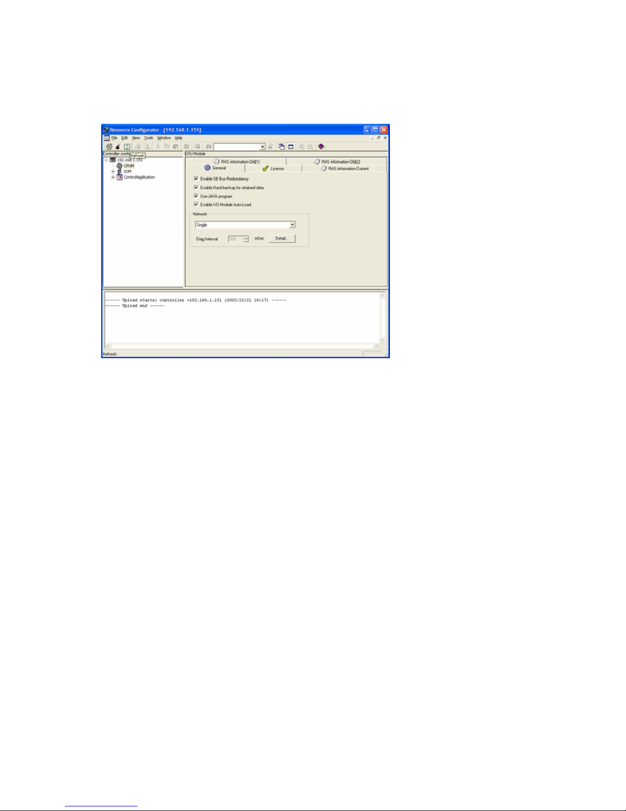
Initializing with resource configurator
The mothod of initial setting operation with resource configurator is described on the instruction manual.
The work flow is described in this chapter. However, refer to the instruction manual for details of each
operation.
1) Setting the IP address
Refer to 5.1 Modification of IP address.
Page 14
5-3 IM 12Y04D01-01
2) Loading the license file
Download the license file that is loaded from the STARDOM web site to ASGW with the resource
configurator.
Refer to online help of resource configurator
3) To enable Java.
4) Setting the network
Ethenet of ASGW has dual or single type and dual type has duplex and separated mode.
Select the type and mode for the system.
Reboot the ASGW. After starting ASGW confirm that the IP address is correct by ping command of PC.
5) Setting th serial port
In the case of Modbus RTU, the communication parameters should be adjusted to a connected device.
Refer to 5.2.
Page 15

4. Engineering
IM 12Y04D01-01 5-2
4.2. Data mapping
Mapped address is setted with one file named “ASGW_MAP.CSV”.
Mapping operation is complete when the file is transfered to ASGW with FTP and the ASGW is rebooted.
ASGW checks the file at startup. Information of error diagnosis is confirmed with Web browser.
At the installation on ASGW a sample file is setted. Mapping operation is realized with modification of the
sample file.
The mapping file does not depend on ASGW, so that the composition of mapped file is available in advance
without ASGW.
*
Example of mapping file
4.3. Loading a mapping file
After the installation of ASGW, turn on the power and connect the ASGW to PC with Ethernet cable.
Open the web browser on PC and input the address of ASGW as http://(IP
address of ASGW).
When the homepage of ASGW is displayed, click the “Mapping File”.
FTP windows appears and account and password are required.
Enter the following characters.
Account: “stardom”
Password: “YOKOGAWA”
Mapping file “ASGW_MAP.CSV” is displayed on FTP window.
Move this file to PC.
#SLAVE, 1
#RETRY, 3
#TOUT,100
**** Station
#STN, 10, GC1000, 192.168.0.10, GC1000Mk2 at SiteA
#STN, 42, GC1000, 192.168.0.42, GC1000Mk2 at SiteB
#STN, 101, ASIU, 192.168.0.101, ASIU
**** Mapping
#MAP, 10, 01001, 1, RUN
#MAP, 42, 01002, 1, RUN
#MAP, 10, 01004, 2, STOP
#MAP, 42, 01005, 2, STOP
#MAP, 10, 11001, 10001, Normal
#MAP, 42, 11002, 10001, Normal
#MAP, 10, 11004, 10002, Error
Page 16

5-3 IM 12Y04D01-01
4.4. Setting
This file consists of text characters. Editing can be done with “Notepad” software, but “MS-Excel” software
is recommended. The edited file should be saved with “CSV” as an extension.
Each line has meaning in the map file. A line beginning with character # is interpreted as a meaningful line.
And a comment line does not begin with character “# “.
#SLAVE, n
This n is the Slave ID when DCS accesses to ASGW with Modbus interface.
#RETRY, m
This m is the number of retry times when a write error occurs.
#TOUT, t
This t is time-out value of characters in the communication between DCS and Modbus RTU. Adjust the
value depending on communication speed. Unit is ms [millisecond] and range is 10 to 5000.
Definition of GC1000MkII/ASIU
This is the setting of analyzer ID. The number of analyzer units that is connected to one ASGW is 31 sets
Every analyzer should be defined by unique StnID number. This StnID is key data on Modbus interface.
#STN Key word
StnID ID number of analyzer (1-254)
StnType Type of analyzer “GC1000” or “ASIU”
IP_Address IP address of GC1000MkII/ASIU
Example “#STN, GC1000,3,192.168.0.1”
Definition of Mapping
This is setting of Modbus address
Refer to the Modbus address tables (Table 3.3-7) for available mapping conditions.
#MAP Key word
StnID ID number of analyzer (defined in #STN)
ASGW_Address Modbus address of ASGW
Target_Address Modbus address of target analyzer
Example: “#MAP,3,11001,10001”
The order of line is not restricted, and blank line is ignored.
Page 17

4. Engineering
IM 12Y04D01-01 5-2
4.5. Transfer to ASGW
Open the FTP window on PC that is shown in 5.3.1
Move the modified mapping file to FTP window.
Restart ASGW after over writing is complete.
4.6. Diagnosis information
After re-starting the ASGW, Open the web browser.
When “Mapping Error” is clicked, the diagnosis information window appears.
The contents are as follows.
a) Out of range addressing
b) Duplicated addressing
c) Invalid combination of mapping
Modify the setting file according to the error that is shown in this window.
If the file includes errors, ASGW ignores the error occurred line on the file.
Page 18

Page 19

5.Additiona Information
IM 12Y04D01-01 5-2
5 Additional Information
This chapter explains how to change the IP address of ASIU/ASGW and the property of serial port.
The tool software that is shown below is installed on PC.
CD-ROM Code Item
NT203AJ-PC11E Resource configurator
5.1 Modification of IP addressing setting
(1) Preparation of PC
Connect the PC on which resource configurator software is installed to ASIU/ASGW with Ethernet
(2) Starting the ASIU/ASGW on the IP address setting mode.
There are two methods of starting the ASIU/ASGW on the IP address setting mode.
One is use of web browser on PC, the other is use of switches on CPU module.
Select one depending on the location of ASIU/ASGW.
During the IP address setting mode, LEDs on CPU module of ASIU/ASGW are indicated as follows.
HRDY: Flashing quickly
RDY: Flashing slowly
CTRL: Not lit
To release this mode, press the RESET button or turn off the power.
A) Method of use the switch on CPU module of ASIU/ASGW
i) Turn on ASIU/ASGW, or press “RESET” button.
ii) ASIU/ASGW starts and during the “HRDY”and “RDY”LED are flashing rapidly (about for two seconds),
press “SHUTDOWN” button once.
iii) ASIU/ASGW starts on IP address setting mode.
B) Method of use web browser on PC.
i) Access to the URL.
URL= http://current
IP address/MNT
User Accout = “stardom”
Page 20

5-3 IM 12Y04D01-01
Password = “YOKOGAWA”
ii) Click the Maintenance Menu
Page 21

5.Additiona Information
IM 12Y04D01-01 5-2
iii) Click the Reboot.
iii) Select the Reboot(IP Address Setting Mode) and press “OK”
ASIU/ASGW restarts on IP address setting mode.
Page 22

5-3 IM 12Y04D01-01
3) Setting IP address
Start the resource configurator software on PC and wait for a message “A new controller is connected”.
When the message appears, select the “Setting IP Address” on “File”menu.
Page 23

5.Additiona Information
IM 12Y04D01-01 5-2
IP address, Subnet mask, Gateway and Time zone parameters are set on this dialogue window.
Reboot the ASIU/ASGW after the setting.
5.2 Modification of serial port setting
In the case of using the Modbus RTU as external interface of ASIU/ASGW this operation is required.
ASIU has one and ASGW has two communication ports and all initial setting data are as follows.
After ASIU/ASGW mode changes to maintenance mode, the communication port is set with the maintenance
windows on web browser.
Refer to the guide of STARDOM FCN/FCJ (IM34P02Q01-01E) about the method of modification.
Setting parameters are “COM1 Port Setting File” or “COM2 Port Setting File”.
Baudrate =9600
DataBitLength =8
StopBitLength =1
Parity =NONE
Page 24

5-3 IM 12Y04D01-01
Page 25

5.Additiona Information
IM 12Y04D01-01 5-2
 Loading...