

Page 1

User ’s
Manual
AQ7280 OTDR
Getting Started Guide
IM AQ7280-02EN
6th Edition
Page 2

Thank you for purchasing the AQ7280 OTDR (Optical Time Domain Reflectometer). This manual focuses on the handling precautions,
basic operations, and specifications of the AQ7280. For correct operation, please read this manual thoroughly before use.
List of Manuals
The AQ7280 comes with the following manuals. Please keep them in a safe place.
Manual Title Manual No. Description
AQ7280 OTDR User’s Manual (included in CD) IM AQ7280-01EN Explains all AQ7280 features, except for the communication
features, and how to use them.
AQ7280 OTDR Getting Started Guide IM AQ7280-02EN This manual.
AQ7280 OTDR Communication Interface
User’s Manual (included in CD)
Model 739883 Battery Pack Handling Precautions IM 739883-01EN Explains the handlling precautions for the battery pack.
AQ7280 OTDR User’s Manual IM AQ7280-92Z1 A manual for China.
739883 Battery Pack User’s Manual IM 739883-92Z1 A manual for China.
* The “EN” and “Z1” in the manual numbers are the language codes.
Contact information of Yokogawa offices worldwide is provided on the following sheet.
Document No. Description
PIM 113-01Z2 List of worldwide contacts
IM AQ7280-17EN Explains the features related to using communication
commands to control the AQ7280.
Notes
• The contents of this manual are subject to change without prior notice as a result of continuing improvements to the instrument’s
performance and functionality. The figures given in this manual may differ from those that actually appear on your screen.
• Every effort has been made in the preparation of this manual to ensure the accuracy of its contents. However, should you have any
questions or find any errors, please contact your nearest YOKOGAWA dealer.
• Copying or reproducing all or any part of the content of this manual without the permission of YOKOGAWA is strictly prohibited.
6th Edition: December 2017 (YMI)
All Rights Reserved, Copyright © 2014, Yokogawa Test & Measurement Corporation
IM AQ7280-02EN
1
Page 3

Trademarks
• Microsoft, Windows, Windows 7, and Windows 8 are either registered trademarks or trademarks of Microsoft Corporation in the United
States and/or other countries.
• Adobe and Acrobat are trademarks of Adobe Systems Incorporated.
• In this manual, the ® and TM symbols do not accompany their respective registered trademark or trademark names.
• Other company and product names are registered trademarks or trademarks of their respective holders.
Revisions
October 2014 1st Edition
July 2015 2nd Edition
January 2016 3rd Edition
July 2016 4th Edition
October 2017 5th Edition
December 2017 6th Edition
2
IM AQ7280-02EN
Page 4

Product Registration
Thank you for purchasing YOKOGAWA products.
YOKOGAWA provides registered users with a variety of information and services.
Please allow us to serve you best by completing the product registration form accessible from our
website.
http://tmi.yokogawa.com/
IM AQ7280-02EN
3
Page 5
Checking the Package Contents
After receiving the product and opening the package, check the items described below. If the wrong items have been delivered, if items
are missing, or if there is a problem with the appearance of the items, contact your nearest YOKOGAWA dealer.
Check that the product that you have received is the same product that you ordered. For reference, the model name, suffix code, and
specifications of the products are listed below.
AQ7280 OTDR Mainframe
xxx-xxxx
Model Suffix
AQ7280 OTDR mainframe
Language -HE English (Multi language
1
Description
2
)
-HM Chinese
-HC Chinese/English
-HK Korean/English
-HR Russian/English
Options /MNT Monitoring function
/SMP Smart Mapper function
/FST Fiber Surface Test function
/LAN Ethernet
/SB Shoulder belt
1 For products whose suffix code contains “Z,” an exclusive manual may be included. Please read it along with the standard manual.
2 For details on multi language, see the options displayed in the language setup menu.
4
IM AQ7280-02EN
Page 6
IM AQ7280-02EN
OTDR unit
xxx-xxxx
Model Suffix
AQ7282A 2WL 1310/1550 nm 38/36 dB
AQ7283A 2WL 1310/1550 nm 42/40 dB
AQ7284A 2WL 1310/1550 nm 46/45 dB
AQ7285A 2WL 1310/1550 nm 50/50 dB
AQ7283E 3WL 1310/1550,1625 nm 42/40, 40 dB (1625 nm port is equipped with a built-in filter)
AQ7283F 3WL 1310/1550,1650 nm 42/40, 40 dB (1650 nm port is equipped with a built-in filter)
AQ7282G 3WL 1310/1490/1550 nm 38/36/36 dB
AQ7283H 3WL 1310/1550/1625 nm 42/40/39 dB
AQ7284H 3WL 1310/1550/1625 nm 46/45/44 dB
AQ7283J 4WL 1310/1383/1550/1625 nm 42/39/40/40 dB
AQ7283K 4WL 1310/1490/1550/1625 nm 42/38/40/40 dB
AQ7282M 2WL 850/1300 nm (MM) 25/27 dB
Connector Adapter
1
Options /PC Power checker
1 The connectors that you select are attached to the OTDR ports prior to shipping.
2 For products whose suffix code contains “Z,” an exclusive manual may be included. Please read it along with the standard manual.
3 Not applicable to AQ7282M.
4 Not applicable to the port 2 of AQ7283E and AQ7283F.
5 Not applicable for 1383 nm of AQ7283J.
2
Description
-USC Universal adapter (SC)
-UFC Universal adapter (FC)
-ULC Universal adapter (LC)
-ASC ASC connector (SC angled physical contact)
-NUA No universal adapter
/SLS Stabilized light source
3, 4
5
3
5
Page 7
Optical power meter module (OPM module)
xxx-xxxx
Model Suffix
2
Description
AQ2780 OPM module Power range: –70 dBm to +10 dBm (CW)
AQ2781 High power OPM module Power range: –50 dBm to +27 dBm (CW)
AQ2780V OPM & VLS module Power range: –70 dBm to +10 dBm (CW)
with Visible Light Source (Connector: Ø2.5 Ferrule)
AQ2781V High power OPM & VLS module Power range: –50 dBm to +27 dBm (CW)
with Visible Light Source (Connector: Ø2.5 Ferrule)
Connector Adapter
1
-SCC Universal adapter (SC)
-FCC Universal adapter (FC)
-LMC Ferrule adapter (Ø1.25)
1 The connectors that you select are attached to the OPM ports prior to shipping.
2 For products whose suffix code contains “Z,” an exclusive manual may be included. Please read it along with the standard manual.
6
IM AQ7280-02EN
Page 8
AQ4780 Visible light source module
xxx-xxxx
IM AQ7280-02EN
Model Suffix
1
Description
AQ4780 VLS module Visible Light Source (Connector: Ø2.5 Ferrule)
1 For products whose suffix code contains “Z,” an exclusive manual may be included. Please read it along with the standard manual.
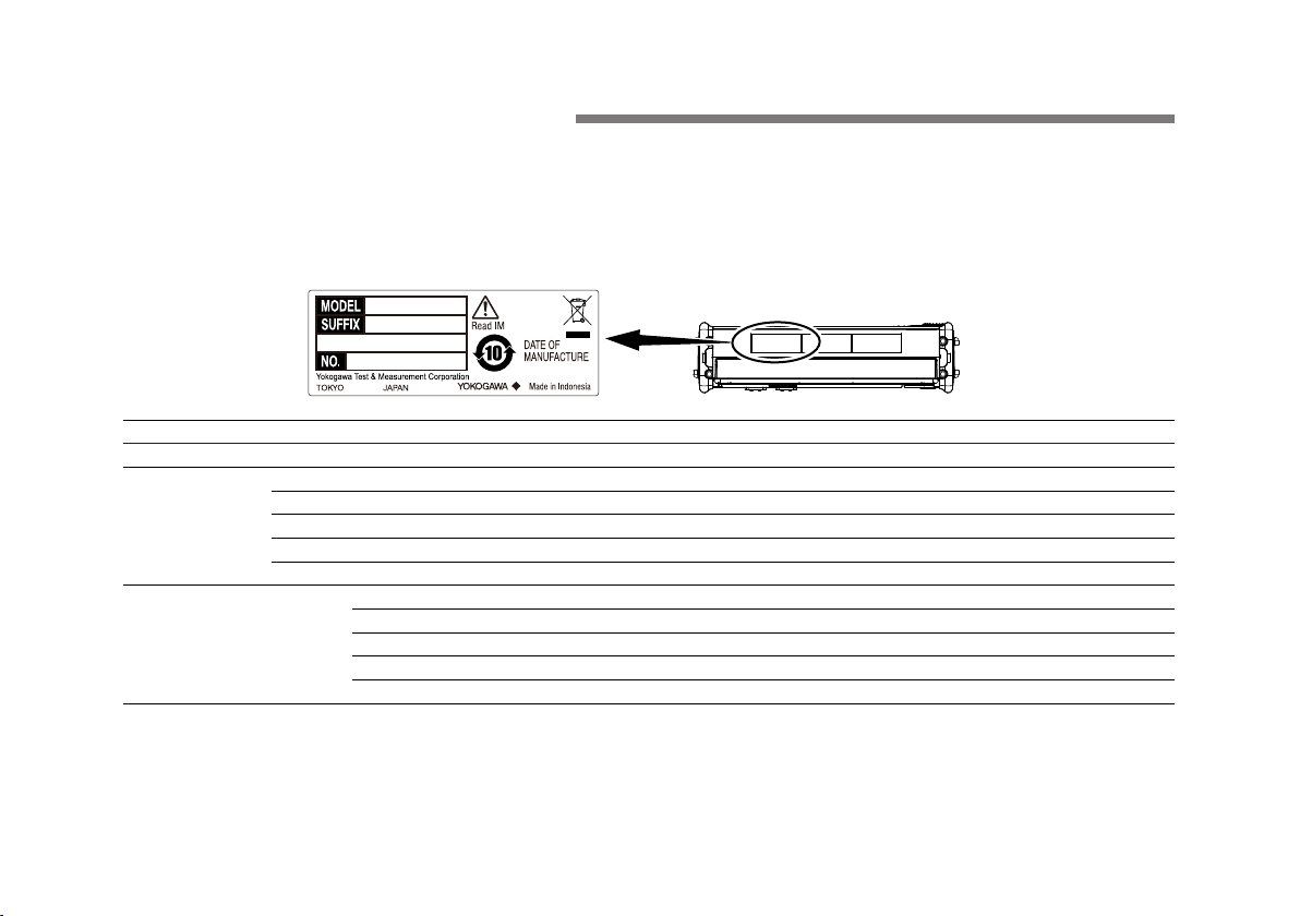
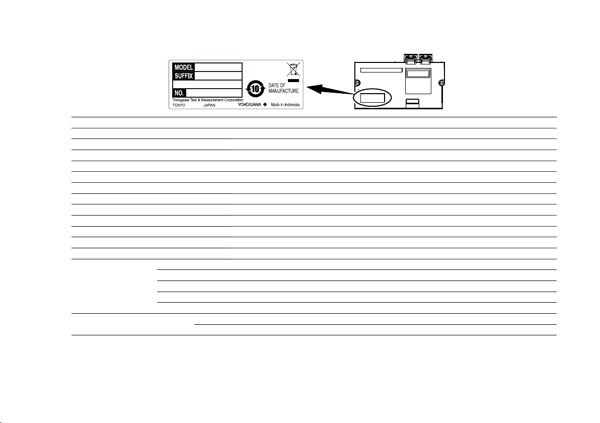
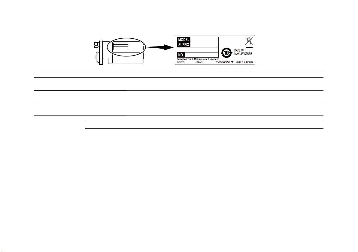
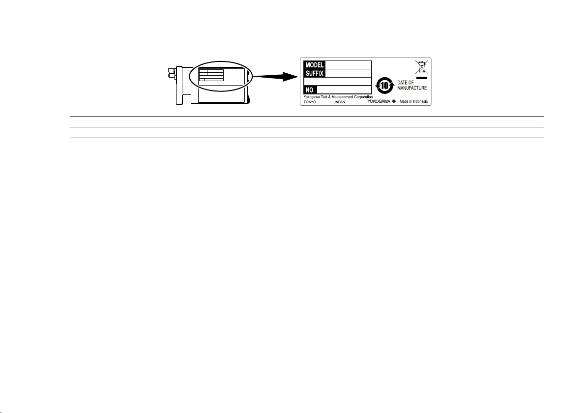
No. (Instrument number)
When contacting the dealer from which you purchased the instrument, please tell them the instrument number.
7
Page 9
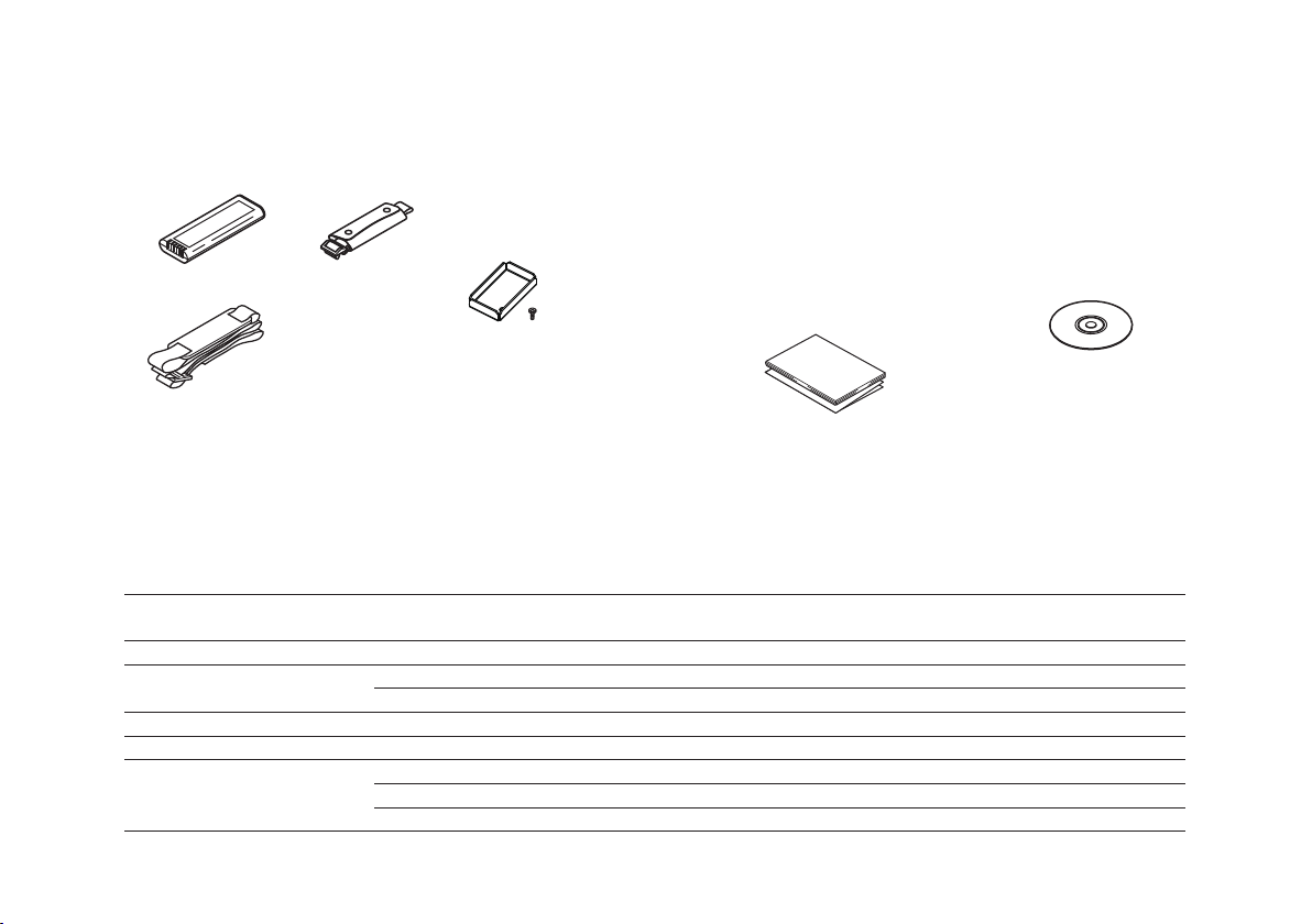
Accessories
Battery pack
Shoulder strap (/SB)
B8070CY
Manuals
Manuals (CD)
You can purchase the printed IM AQ7280-01EN and IM AQ7280-17EN manuals separately. Contact your nearest YOKOGAWA dealer to
purchase a copy.
Hand strap
Cover Bracket
The instrument is shipped with the following accessories. Make sure that all accessories are present and undamaged.
(lithium-ion)
739883
1 Included with models that have the /SB option installed.
2 If a VLS or optical power meter module has not been ordered along with the OTDR mainframe (AQ7280), the cover is attached to the OTDR
3
Optional Accessories (Sold separately)
The following optional accessories are available for purchase separately. For information about ordering accessories, contact your
nearest YOKOGAWA dealer.
Name Model or Component
Soft carrying case 739860 — —
AC adapter 739873 Except for EU, ferrite core included IM 739873-01EN
Battery pack 739883 — IM 739883-01EN
Shoulder strap B8070CY — —
Additional option license for
AQ7280
8
1
mainframe.
B8070CX
(for optical power meter
module/visible light source
module slot)
B8107DE
2
Screw (M4 x 5)
• IM AQ7280-02EN
(this manual)
• IM 739883-01EN
(for battery pack)
• PIM 113-01Z2
(list of worldwide contacts)
• IM AQ7280-92Z1 (for China)
• IM 739883-92Z1 (for China)
B8107VA
• IM AQ7280-01EN
(User’s manual)
• IM AQ7280-17EN
(for communication
interface)
Notes Manual No.
Number
739872 For EU, ferrite core included IM 739872-01EN
735050-MNT Monitoring function —
735050-SMP Smart mapper function —
735050-FST Fiber surface test function —
3
IM AQ7280-02EN
Page 10

IM AQ7280-02EN
Name Model or Component
Number
Universal adapter (SC) SU2005A-SCC for OTDR unit —
Universal adapter (FC ) SU2005A-FCC for OTDR unit —
Universal adapter (LC) SU2005A-LCC for OTDR unit —
Connector adapter (SC) 735480-SCC for OPM module —
Connector adapter (FC) 735480-FCC for OPM module —
Ferrule adapter (Ø1.25) 735481-LMC for OPM module —
Ferrule adapter (Ø2.5) 735481-SFC for OPM module —
Notes Manual No.
Manual CD
WARNING
Never play this manual CD, which contains the user’s manuals, in an audio CD player. Doing so may cause loss of
hearing or speaker damage due to the large sounds that may be produced.
French
AVERTISSEMENT
Ce CD contient les manuels d’utilisation. Ne jamais insérer ce CD dans un lecteur de CD audio.
Cela pourrait entraîner une perte d’audition ou l’endommagement des enceintes en raison du volume potentiellement
élevé des sons produits.
The English folder of manual CD contains PDF files of the following manuals. The PDFs of the Japanese manuals are included in the
manual CD.
File Name Manual Title Manual No.
Features and Operation Manual.pdf AQ7280 OTDR User’s Manual IM AQ7280-01EN
Communication Interface.pdf AQ7280 OTDR Communication Interface User’s Manual IM AQ7280-17EN
To view above manuals you need Adobe Reader 5.0 or later.
9
Page 11

Safety Precautions
This product is designed to be used by a person with specialized knowledge.
The general safety precautions described herein must be observed during all phases of operation. If the instrument is used in a manner
not specified in this guide, the protection provided by the instrument may be impaired.
This manual is an essential part of the product; keep it in a safe place for future reference. YOKOGAWA assumes no liability for the
customer’s failure to comply with these requirements.
The following symbols are used on this instrument.
Warning: handle with care. Refer to the user’s manual or service manual. This symbol appears on dangerous locations on the
instrument which require special instructions for proper handling or use. The same symbol appears in the corresponding place in
the manual to identify those instructions.
Hazard, radiation of laser apparatus.
Direct current
Stand-by
French
Avertissement : À manipuler délicatement. Toujours se reporter aux manuels d’utilisation et d’entretien. Ce symbole a été apposé
aux endroits dangereux de l’instrument pour lesquels des consignes spéciales d’utilisation ou de manipulation ont été émises.
Le même symbole apparaît à l’endroit correspondant du manuel pour identifier les consignes qui s’y rapportent
Danger : Appareil laser à rayonnement.
Courant direct
10
Veille
IM AQ7280-02EN
Page 12

Failure to comply with the precautions below could lead to injury or death.
WARNING
Use the Instrument Only for Its Intended Purpose
This optical measuring instrument is designed to measure the optical characteristics of light sources and evaluate their
performance. Do not use this instrument for anything other than as an optical measuring instrument.
Check the Physical Appearance
Do not use the instrument if there is a problem with its physical appearance.
AC Adapter
Do not use the other than AC adapter designed exclusively for the AQ7280.
Battery Pack
Only use the AQ7280 battery pack. Do not use this battery pack with other instruments. Only use the AQ7280 to
charge the battery pack. If the battery pack is still charging after 6 hours, stop charging it immediately. Your clothing
may be damaged or you may be injured if you come in contact with the electrolyte due to fluid leakage or the battery
pack exploding. Because the electrolyte may cause loss of eyesight, if it comes in contact with your eyes, immediately
wash the affected area with clean water, and consult a doctor as soon as possible. When you change the battery
pack, be sure to turn the AQ7280 off, and detach the AC adapter power supply from the AQ7280. Failure to do so may
lead to electric shock or other accidents. Do not throw the battery pack into fire or heat it. Such actions are dangerous
as they may cause the battery pack to explode or the electrolyte to be sprayed about. Follow the additional handling
precautions that are included in the battery pack’s user’s manual.
Laser Beam
Do not look directly or indirectly into the laser beam or at a specular reflection of the beam without protective equipment.
Do not aim the laser beam at the eye. The laser beam may cause blindness or damage to your eyes. Attach the cover
to the optical connector when it is not in use. Turn the power OFF when you are cleaning the AQ7280.
Connecting Optical Fiber Cables
Use optical fiber cable connectors that conform to the included universal adapter (the universal adapter specified by the
suffix code).
IM AQ7280-02EN
11
Page 13

Apply Correct Signals to the Optical Connectors
Do not apply light that is –5 dBm or greater to the OTDR unit (AQ7282 series) optical connectors (PORT1 and PORT2).
Doing so may damage the OTDR unit.
Do not apply light that is +10 dBm or greater to the OPM module (AQ2780, AQ2780V). Do not apply light that is
+27 dBm or greater to the high power OPM module (AQ2781, AQ2781V). Doing so may damage the OPM module.
Do Not Operate in an Explosive Atmosphere
Do not use the instruments in the presence of flammable gasses or vapors. Doing so is extremely dangerous.
Do Not Remove the Covers or Disassemble or Alter the Instrument
Only qualified YOKOGAWA personnel may remove the covers and disassemble or alter the instrument.
Installation Position
Handling the stand without firmly supporting the instrument can be dangerous. Only handle the stand when the
instrument is on a stable surface.
CAUTION
Operating Environment Limitations
This product is a Class A (for industrial environments) product. Operation of this product in a residential area may cause
radio interference in which case the user will be required to correct the interference.
12
IM AQ7280-02EN
Page 14

French
AVERTISSEMENT
Utiliser l’instrument aux seules fins prévues
Cet instrument de mesure optique est prévu pour mesurer les caractéristiques optiques des sources lumineuses et
évaluer leur performance. Ne pas utiliser cet instrument à d’autres fins que celles de mesure optique.
Inspecter l’apparence physique
Ne pas utiliser l’instrument si son intégrité physique semble être compromise.
Adaptateur c.a.
Utiliser exclusivement l’adaptateur c.a. prévu pour l’AQ7280.
Pack de batteries
Utiliser exclusivement le pack de batteries de l’AQ7280. Ne pas utiliser ce pack de batteries avec d’autres instruments.
Recharger le pack de batteries à l’aide de l’AQ7280 uniquement. Si le pack de batteries est encore en charge au bout
de 6 heures, interrompre la charge. Tout contact avec l’électrolyte échappé en raison d’une fuite ou d’une explosion du
pack de batteries peut endommager les vêtements ou causer des blessures. L’électrolyte peut entraîner la cécité, par
conséquent, en cas de contact avec les yeux, rincer immédiatement à l’eau et consulter un médecin dans les plus brefs
délais. Lors du remplacement du pack de batteries, toujours mettre l’AQ7280 hors tension et débrancher l’adaptateur c.a.
de l’AQ7280. Le non-respect de cette consigne peut entraîner un choc électrique ou tout autre accident. Tenir le pack
de batteries éloigné de toute source de chaleur et des flammes pour éviter le risque d’explosion du pack de batteries
ou de déversement d’électrolyte. Respecter les consignes de manipulation supplémentaires fournies dans le manuel
d’utilisation du pack de batteries.
Faisceau laser
Ne pas fixer directement ou indirectement le faisceau laser, ni la réflexion spéculaire du faisceau en l’absence
d’équipement de protection. Ne pas orienter le faisceau laser en direction des yeux. Le faisceau laser peut entraîner la
cécité ou causer des lésions oculaires. Recouvrir le connecteur optique à l’aide du cache pendant les périodes de nonutilisation. Mettre l’AQ7280 HORS tension pendant son nettoyage.
IM AQ7280-02EN
13
Page 15

Connexion des câbles à fibre optique
Utiliser des connecteurs de câbles à fibre optique conformes à l’adaptateur universel fourni (adaptateur universel
indiqué par le suffixe).
Envoyer les signaux corrects aux connecteurs optiques
Ne pas appliquer de signal de –5 dBm ou plus aux connecteurs optiques de l’unité OTDR (série AQ7282) (PORT1 et
PORT2).
Cela pourrait endommager l’unité OTDR.
Ne pas appliquer de signal de +10 dBm ou plus au module OPM (AQ2780, AQ2780V). Ne pas appliquer de signal de
+27 dBm ou plus au module OPM haute puissance (AQ2781, AQ2781V). Cela pourrait endommager le module OPM.
Ne pas utiliser dans un environnement explosif
Ne pas utiliser l’instrument en présence de gaz ou de vapeurs inflammables. Cela pourrait être extrêmement
dangereux.
Ne pas retirer le capot, ni démonter ou modifier l’instrument
Seul le personnel YOKOGAWA qualifié est habilité à retirer le capot et à démonter ou modifier l’instrument. Certains
composants à l’intérieur de l’instrument sont à haute tension et par conséquent, représentent un danger.
Position d’installation
Lorsque vous manipulez les pieds ou le support escamotable, soutenez toujours l’instrument fermement. Prendre les
précautions suivantes.
ATTENTION
Limitations relatives à l’environnement opérationnel
Ce produit est un produit de classe A (pour environnements industriels). L’utilisation de ce produit dans un zone
résidentielle peut entraîner une interférence radio que l’utilisateur sera tenu de rectifier.
14
IM AQ7280-02EN
Page 16
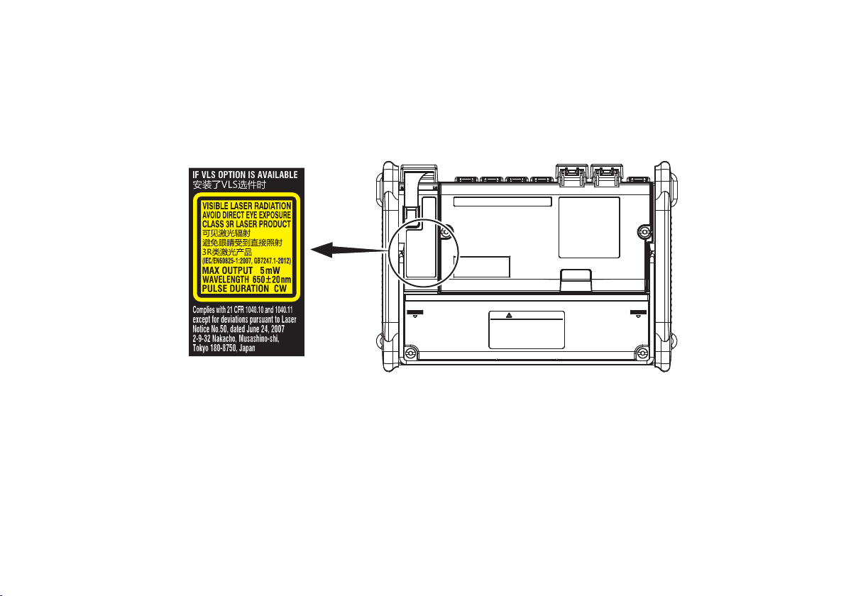
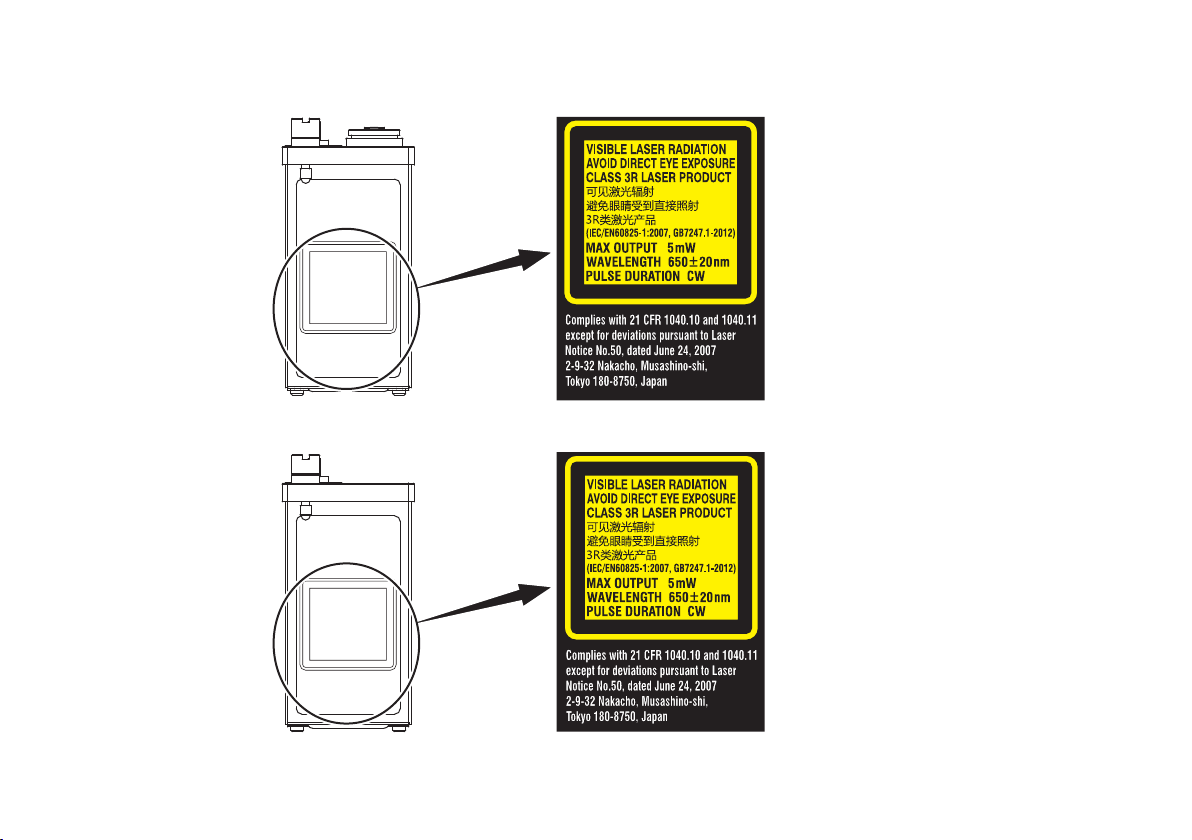
Safety Precautions for Laser Products
Laser Class 3R Label
Avoid direct eye exposure.
This instrument uses a laser light source. This instrument is a Class 1M and Class 3R laser product as defined by IEC/EN60825-1:2007
Safety of Laser Products—Part1: Equipment classification and requirements. In addition, this instrument complies with 21 CFR 1040.10
except for deviations pursuant to Laser Notice No. 50, dated June 24, 2007.
Mainframe
IM AQ7280-02EN
15
Page 17

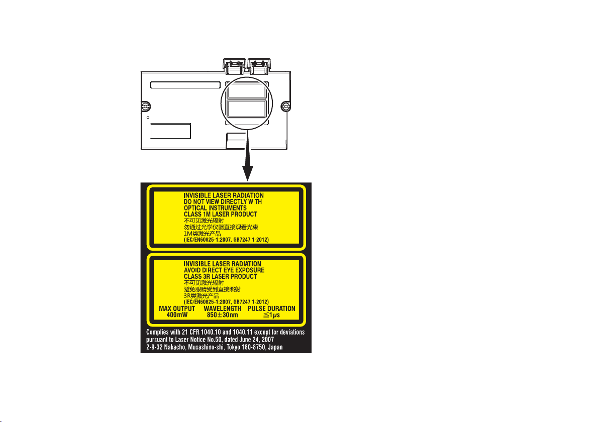
OTDR unit (AQ7284A, AQ7285A, AQ7284H, AQ7283J, AQ7283K)
loupe, magnifying glass, or microscope,
Laser Class 1M Label
Using an optical instrument, such as a
when observing the laser beam from
a distance of less than 100 mm may
cause eye injury.
Laser Class 3R Label
Avoid direct eye exposure.
16
IM AQ7280-02EN
Page 18
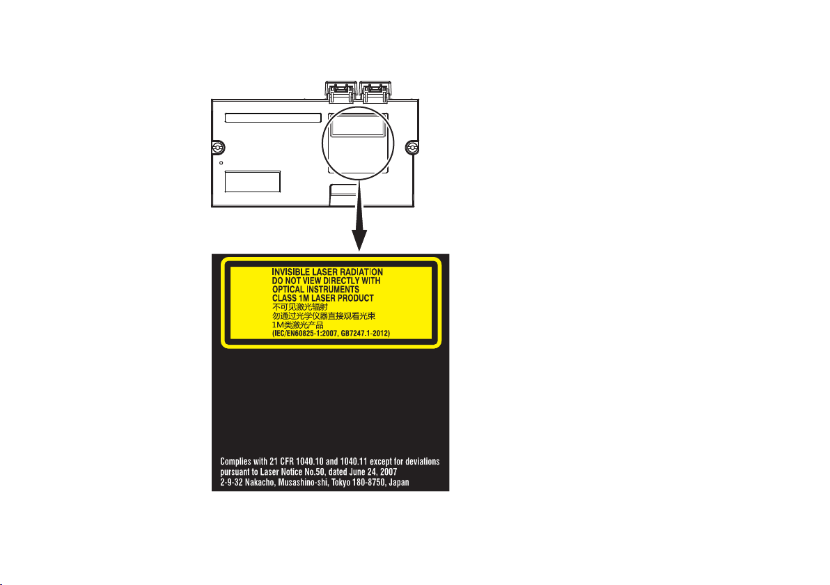
OTDR unit (AQ7282A, AQ7283A, AQ7283E, AQ7283F, AQ7282G, AQ7283H)
Laser Class 1M Label
Using an optical instrument, such as a
loupe, magnifying glass, or microscope,
when observing the laser beam from
a distance of less than 100 mm may
cause eye injury.
IM AQ7280-02EN
17
Page 19
OTDR unit (AQ7282M)
loupe, magnifying glass, or microscope,
Laser Class 1M Label
Using an optical instrument, such as a
when observing the laser beam from
a distance of less than 100 mm may
cause eye injury.
Laser Class 3R Label
Avoid direct eye exposure.
18
IM AQ7280-02EN
Page 20
OPM module (AQ2780V, AQ2781V)
Laser Class 3R Label
Avoid direct eye exposure.
VLS module (AQ4780)
Laser Class 3R Label
Avoid direct eye exposure.
IM AQ7280-02EN
19
Page 21

OTDR unit
Model Class Center
Maximum Output Power
Wavelength
AQ7282A 1M 1310 nm/1550 nm CW: 50 mW@1310 nm/1550 nm
PULSE: 200 mW@1310 nm/1550 nm
PULSE width: 20 μs@1310 nm/1550 nm, Duty: ≤ 3.0%
AQ7283A 1M 1310 nm/1550 nm CW: 50 mW@1310 nm/1550 nm
PULSE: 200 mW@1310 nm/1550 nm
PULSE width: 20 μs@1310 nm/1550 nm, Duty: ≤ 3.0%
AQ7284A 3R 1310 nm CW: 140 mW@1310 nm/1550 nm
1M 1550 nm
PULSE: 500 mW@1310 nm/1550 nm
PULSE width: 20 μs@1310 nm/1550 nm, Duty: ≤ 3.0%
AQ7285A 3R 1310 nm CW: 140 mW@1310 nm/1550 nm
1M 1550 nm
AQ7283E 1M 1310 nm/1550 nm,
1625 nm
PULSE: 500 mW@1310 nm/1550 nm
PULSE width: 20 μs@1310 nm/1550 nm, Duty: ≤ 3.0%
CW: 50 mW@1310 nm/1550 nm, 1625 nm
PULSE: 200 mW@1310 nm/1550 nm, 1625 nm
PULSE width: 20 μs@1310 nm/1550 nm, 1625 nm, Duty: ≤ 3.0%
AQ7283F 1M 1310 nm/1550 nm,
1650 nm
CW: 50 mW@1310 nm/1550 nm/1650 nm
PULSE: 200 mW@1310 nm/1550 nm/1650 nm
PULSE width: 20 μs@1310 nm/1550 nm/1650 nm, Duty: ≤ 3.0%
AQ7282G 1M 1310 nm/1490 nm/
1550 nm
CW: 50 mW@1310 nm/1490 nm/1550 nm
PULSE: 200 mW@1310 nm/1490 nm/1550 nm
PULSE width: 20 μs@1310 nm/1490 nm/1550 nm, Duty: ≤ 3.0%
AQ7283H 1M 1310 nm/1550 nm/
1625 nm
CW: 50 mW@1310 nm/1550 nm/1625 nm
PULSE: 200 mW@1310 nm/1550 nm/1625 nm
PULSE width: 20 μs@1310 nm/1550 nm/1625 nm, Duty: ≤ 3.0%
AQ7284H 3R 1310 nm CW: 140 mW@1310 nm/1550 nm/1625 nm
1M 1550 nm/1625 nm
PULSE: 500 mW@1310 nm/1550 nm/1625 nm
PULSE width: 20 μs@1310 nm/1550 nm/1625 nm, Duty: ≤ 3.0%
1
Mode Field
Diameter
Beam
Divergence
9 μm 11.5°
9 μm 11.5°
9 μm 11.5°
9 μm 11.5°
9 μm 11.5°
9 μm 11.5°
9 μm 11.5°
9 μm 11.5°
9 μm 11.5°
20
IM AQ7280-02EN
Page 22

Model Class Center
Maximum Output Power
1
Wavelength
AQ7283J 3R 1310 nm CW: 140 mW@1310 nm/1383 nm/1550 nm/1625 nm
1M 1383 nm/1550 nm/
1625 nm
PULSE: 500 mW@1310 nm/1383 nm/1550 nm/1625 nm
PULSE width: 20 μs@1310 nm/1383 nm/1550 nm/1625 nm,
Duty: ≤ 3.0%
AQ7283K 3R 1310 nm CW: 140 mW@1310 nm/1490 nm/1550 nm/1625 nm
1M 1490 nm/1550 nm/
1625 nm
PULSE: 500 mW@1310 nm/1490 nm/1550 nm/1625 nm
PULSE width: 20 μs@1310 nm/1490 nm/1550 nm/1625 nm,
Duty: ≤ 3.0%
AQ7282M 3R 850 nm CW: 5 mW@850 nm
50 mW@1300 nm
1M 1300 nm
PULSE: 400 mW@850 nm/1300 nm
PULSE width: 1 μs@850 nm, Duty: ≤ 2.5%
PULSE width: 5 μs@1300 nm, Duty: ≤ 1.2%
1 Under single fault conditions.
Mode Field
Diameter
Beam
Divergence
9 μm 11.5°
9 μm 11.5°
50 μm 23.1°
IM AQ7280-02EN
OPM/VLS module
Model Class Center
Maximum Output Power
Wavelength
AQ2780V 3R 650 nm CW: 5 mW 9 μm 11.5°
AQ2781V 3R 650 nm CW: 5 mW 9 μm 11.5°
AQ4780 3R 650 nm CW: 5 mW 9 μm 11.5°
1 Under single fault conditions.
1
Mode Field
Diameter
Beam
Divergence
21
Page 23

Sales in Each Country or Region
Waste Electrical and Electronic Equipment (WEEE), Directive
(This directive is valid only in the EU.)
This product complies with the WEEE Directive marking requirement. This marking indicates that you must not discard this
electrical/electronic product in domestic household waste.
Product Category
With reference to the equipment types in the WEEE directive, this product is classified as a “Monitoring and Control
instrumentation” product. When disposing products in the EU, contact your local Yokogawa Europe B.V. office.
Do not dispose in domestic household waste.
EU Battery Directive
(This directive is valid only in the EU.)
Batteries are included in this product. This marking indicates they shall be sorted out and collected as ordained in the EU battery
directive.
Battery type:
1. Lithium battery
You cannot replace batteries by yourself. When you need to replace batteries, contact your local Yokogawa Europe B.V.
office.
2. Lithium-ion battery pack (739883)
When you dispose battery pack, do not disassemble it.
When you remove battery pack from this product and dispose it, discard it in accordance with domestic law concerning
disposal.Take a right action on waste batteries, because the collection system in the EU on waste batteries are regulated.
For instructions on how to remove the battery pack, see pages 35 to 38 in this manual.
22
IM AQ7280-02EN
Page 24

Recycle Mark
Do not dispose together with normal garbage. To protect the environment, please dispose according to the recycling ordinances
in your area.
Authorized Representative in the EEA
Yokogawa Europe B.V. is the authorized representative of Yokogawa Test & Measurement Corporation for this product in the EEA. To
contact Yokogawa Europe B.V., see the separate list of worldwide contacts, PIM 113-01Z2.
IM AQ7280-02EN
23
Page 25

Conventions Used in This Guide
Notes
The notes and cautions in this guide are categorized using the following symbols.
Improper handling or use can lead to injury to the user or damage to the instrument. This symbol appears on the
instrument to indicate that the user must refer to the user’s manual for special instructions. The same symbol appears
in the corresponding place in the user’s manual to identify those instructions. In the manual, the symbol is used in
conjunction with the word “WARNING” or “CAUTION.”
WARNING
CAUTION
French
Une manipulation ou une utilisation incorrectes risquent de blesser l’utilisateur ou d’endommager l’instrument. Ce
AVERTISSEMENT
ATTENTION
Calls attention to information that is important for proper operation of the instrument.
Note
24
Calls attention to actions or conditions that could cause serious or fatal injury to the user, and precautions that can
be taken to prevent such occurrences.
Calls attention to actions or conditions that could cause light injury to the user or damage to the instrument or
user’s data, and precautions that can be taken to prevent such occurrences.
symbole apparaît sur l’instrument pour indiquer à l’utilisateur qu’il doit se reporter au manuel de l’utilisateur afin d’y lire
les instructions spécifiques correspondantes. Ce même symbole apparaît à la section correspondante du manuel de
l’utilisateur pour signaler lesdites instructions. Dans le manuel de l’utilisateur, ce symbole est accompagné des termes
AVERTISSEMENT et ATTENTION.
Attire l’attention sur des gestes ou des conditions susceptibles de provoquer des blessures graves (voire
mortelles), et sur les précautions de sécurité pouvant prévenir de tels accidents.
Attire l’attention sur des gestes ou des conditions susceptibles de provoquer des blessures légères ou
d’endommager l’instrument ou les données de l’utilisateur, et sur les précautions de sécurité susceptibles de
prévenir de tels accidents.
IM AQ7280-02EN
Page 26

Contents
List of Manuals ........................................................................1
Product Registration ................................................................3
Checking the Package Contents .............................................4
Safety Precautions ................................................................10
Sales in Each Country or Region ..........................................22
Conventions Used in This Guide ...........................................24
Names and Functions of Parts
Making Preparations for Measurements
Operating Precautions ..........................................................30
Installing and Removing the OTDR Unit ...............................31
Installing and Removing the OPM/VLS Module ....................33
Loading and Removing the Battery Pack ..............................35
Connecting the AC Adapter ...................................................39
Inserting and Removing an SD Card ....................................40
Attaching the Strap ................................................................41
Connecting Optical Fiber Cables ..........................................42
Turning On the Power ...........................................................45
Connecting Peripheral Devices .............................................47
...................................27
................30
Common Operations
Top Screen ............................................................................49
Screen Explanation ...............................................................50
Rotary Knob and Arrow Key Operations ...............................52
Touch Panel Operations ........................................................53
Setting the Date and Time .....................................................55
Entering Character Strings ....................................................56
.......................................................49
Optical Pulse Measurement in Simple Mode
Configuring the Simple Mode Conditions ..............................57
Performing Averaged Measurements .................................... 58
Analysis Using the Emulation Software
Specifications
AQ7280 OTDR Mainframe ....................................................61
OTDR Unit .............................................................................63
OPM/VLS modules ................................................................69
General specifications ...........................................................70
External Dimensions .............................................................71
.....................................................................61
................60
.......57
IM AQ7280-02EN
25
Page 27

Memo
26
IM AQ7280-02EN
Page 28

Press to turn the AQ7280 on and off.
ESC key
Press to return to the previous
menu or to cancel the current
operation.
Soft keys
Press to select the menu
items that are displayed on
the right side of the screen.
LCD
Used to perform touch panel
operations.
LASER lamp
IM AQ7280-02EN
UTIL key
Press to display the utility menu.
Names and Functions of Parts
Front Panel
Top Panel
REAL TIME key
Press to start or stop real-time optical-pulse measurement.
CHARGE LED
Lighting: The battery pack is being charged
Off: The battery pack is finished charging
Power switch
Illuminates while the laser is being output.
MENU key
Press to display the top menu.
Rotary knob
Turn to select features, change settings, and
move the cursor.
FILE key
Press to save and load measured results and
other data.
SCALE key
Press to set the waveform displayscale.
ENTER key
Press to confirm procedures and settings.
Arrow keys
Press to change values, move between digits,
and move the cursor.
SETUP key
Press to display the measurement conditions,
system setup, and file operation menus.
AVG key
Press to start or stop averaged optical-pulse
measurement.
ON LED
Illuminates in green when the AQ7280 is running
Illuminates in red when the battery is low.
27
Page 29

DC power supply connector
Used to connect the AC adapter
(Sold separately).
Used to connect the AQ7280 to a network
Names and Functions of Parts
OTDR Unit
OTDR/light source/power checker port
(OTDR Unit, port 1)
Top Panel
Rear Panel
OTDR/light source port
(OTDR Unit, port 2)
USB type-B port (Mini-B)
Used to control the AQ7280 from a PC through
communication commands or to access the AQ7280
internal memory from a PC.
28
Optical power meter/visible light source
module slot
Ethernet port (optional)
Front Panel
USB type-A ports
Used to connect a USB memory device
or a USB printer.
IM AQ7280-02EN
Page 30

Rear and Side Panels
Shoulder strap bracket
Hand strap brackets
OTDR unit installation screws
Pull the stand out to use the
Names and Functions of Parts
OTDR Unit
Stand
AQ7280 in a tilted position.
Battery cover*
IM AQ7280-02EN
Battery cover screws
*: SD card slot is located under
the battery pack.
29
Page 31

Making Preparations for Measurements
Operating Precautions
Safety Precautions
If you are using this instrument for the first time, make sure to thoroughly read “Safety Precautions,” on pages 10 to 21.
Do Not Remove the Case
Do not remove the case from the instrument. Doing so is extremely dangerous. For internal inspection and adjustment, contact your
nearest YOKOGAWA dealer.
Unplug If Abnormal Behavior Occurs
If you notice smoke or unusual odors coming from the instrument, immediately turn off the power, unplug the power cord, and contact
your nearest YOKOGAWA dealer.
Use the AC Adapter and Power Cord Correctly
Do not place objects on top of the AC adapter or power cord, and keep them away from heat sources. When removing the plug from the
power outlet, do not pull on the cord. Pull from the plug. If the AC adapter or power cord is damaged, contact your nearest YOKOGAWA
dealer. Refer to page 3 to 6 for the part number to use when placing an order.
General Handling Precautions
Do Not Place Objects on Top of the Instrument
Never place objects such as other instruments or objects that contain water on top of the instrument. Doing so may damage the
instrument.
Do Not Subject the Inputs and Outputs to Mechanical Shock
If the I/O connectors or adapters are subjected to mechanical shock, they may be damaged. The instrument may not perform
measurements correctly due to damage or deformation that is not visible to the naked eye.
Do Not Scratch the LCD
Because the LCD can be easily scratched, do not allow any sharp objects near it. Also, do not apply vibration or shock to it. Furthermore,
do not apply strong shock to the LCD or place objects on top of it.
During Extended Periods of Non-Use
Unplug the power cord from the outlet. Remove the battery pack from the instrument.
When Carrying the Instrument
Remove the power cord and connecting cables. When carrying the instrument, grasp the protector or the attached strap firmly.
30
IM AQ7280-02EN
Page 32

Installing and Removing the OTDR Unit
WARNING
Do not install or remove an OTDR unit with the AQ7280 turned on.
CAUTION
There is a ground terminal at the OTDR unit installation area of the OTDR mainframe. Be careful not to injure your
hand, or other parts of your body, on it.
French
AVERTISSEMENT
Ne pas installer, ni retirer d’unité OTDR lorsque l’AQ7280 est sous tension.
ATTENTION
Une borne de terre se trouve dans la zone d’installation de l’unité OTDR du mainframe OTDR. Faites attention de ne
pas vous blesser à la main ou toute autre partie du corps.
Making Preparations for Measurements
IM AQ7280-02EN
31
Page 33

Making Preparations for Measurements
Installation screw
Installation screw
A part where you can
Installation screw
Installation screw
A part where you can
Installing an OTDR Unit
On a soft, flat surface, place the OTDR mainframe
with the rear panel facing up.
1.
2.
3.
The proper tightening torque is about 0.6 N-m.
Removing the OTDR Unit
1.
2.
Align the connector of the OTDR unit to that of
the OTDR mainframe, and gently push down the
OTDR unit.
Push the part shown in the following figure with a
bit of strong force until you hear a click.
Check that the OTDR unit is not loose, and then
fasten the screws with a coin or a flat-bladed
screwdriver.
Loosen the OTDR attachment screws with a coin
or a flat-bladed screwdriver until the screw head
moves up and down. The screws are designed so
that they do not come off the OTDR unit.
Pull up on the part of the OTDR unit where
you can insert your finger. If the screws are not
completely loose, loosen them further.
insert your finger
OTDR Unit
Connecter
Ground teminal
OTDR Unit
insert your finger
32
IM AQ7280-02EN
Page 34

Installing and Removing the OPM/VLS Module
Installation screw
Optical Power Meter or
WARNING
Do not install or remove an optical power meter or visible light source module with the AQ7280 turned on.
French
AVERTISSEMENT
Ne pas installer, ni retirer un mesureur de puissance optique ou un module de source lumineuse visible lorsque l’AQ7280
est sous tension.
Installing an Optical Power Meter or Visible Light
Source Module
Remove the rubber cover from the optical power meter/
1.
visible light source module slot of the OTDR mainframe.
If a cover bracket is attached to the slot, remove the
screw with a Phillips screwdriver, and remove the bracket.
Insert the optical power meter or visible light source
2.
module into the slot of the OTDR mainframe. Be careful
of the orientation.
Gently push the optical power meter or visible light source
3.
module until you hear a click.
Tighten the attachment screw with a coin or a flat-bladed
4.
screwdriver.
The proper tightening torque is about 0.6 N-m
Making Preparations for Measurements
Visible Light Source
Module
Rubber cover
IM AQ7280-02EN
33
Page 35

Cover bracket
Screw
Making Preparations for Measurements
Removing the Optical Power Meter or Visible Light Source Module
Remove the rubber cover from the optical power meter/visible light source module slot of the OTDR mainframe.
1.
Loosen the optical power meter or visible light source module attachment screw with a coin or a flat-bladed screwdriver until the
2.
screw head moves up and down. The screw is designed so that it does not come off the module.
Hold the screw and pull the optical power meter or visible light source module up from the OTDR mainframe.
3.
Attach the included cover bracket. Tighten the screw (M4) with a Phillips screwdriver.
4.
The proper tightening torque is about 1.2 N-m.
Note
If you are not going to install an optical power meter or visible light source module, attach the cover bracket to prevent foreign
substances from entering the slot.
34
IM AQ7280-02EN
Page 36

Loading and Removing the Battery Pack
WARNING
• Do not connect or disconnect the battery pack while electricity is being supplied by the AC adapter.
• To prevent problems before they occur, periodically inspect the battery pack exterior to confirm that there is no damage
such as cracks or deformations and to confirm that there is no fluid leakage.
• Only use 739883 battery pack. Do not use this battery pack with other instruments.
• Use the AQ7280 to charge the battery pack. Maintain the correct environmental conditions when the battery pack is
charging. Failure to do so can cause fluid leakage, heating, smoke, explosions, or fire.
You need a separately sold AC adapter to charge the battery pack.
• Follow the handling precautions that are included in the battery pack’s user’s manual.
• The battery pack is made of lithium-ion cells. When transporting the AQ7280, remove the battery pack.
• For information on transporting lithium-ion batteries by air, see the requirement for each packing instruction (lithium
battery packing instruction Section II) in the latest IATA Dangerous Goods Regulations.
French
AVERTISSEMENT
• Ne pas installer, ni déposer le pack de batteries lorsque l’électricité est alimentée par l’adaptateur c.a.
• À titre préventif, inspecter régulièrement le boîtier extérieur du pack de batteries afin de déceler tout signe
d’endommagement, comme l’apparition de fissures ou de déformations, et vérifier qu’il n’y a aucune fuite.
• Utiliser exclusivement le pack de batteries 739883. Ne pas utiliser ce pack de batteries avec d’autres instruments.
• Recharger le pack de batteries à l’aide de l’AQ7280. Respecter les consignes environnementales prescrites pour la
recharge du pack de batteries, afin d’éviter les risques de fuite, de surchauffe, de fumée, d’explosion ou d’incendie.
L’adaptateur c.a nécessaire pour recharger le pack de batteries est vendu séparément.
• Respecter les consignes de manipulation indiquées dans le manuel d’utilisation du pack de batteries.
•
Le pack de batteries est composé de cellules au lithium-ion. Avant de transporter l’AQ7280, déposer le pack de batteries.
• Pour toute information sur le transport aérien des batteries au lithium-ion, consulter les exigences énoncées dans le
Règlement de l’IATA sur le transport des marchandises dangereuses (Section II pour les batteries au lithium).
Making Preparations for Measurements
IM AQ7280-02EN
35
Page 37

Stand
Making Preparations for Measurements
CAUTION
The battery pack weights approximately 500 g. Be careful not to drop it on your feet or hands.
French
ATTENTION
Le pack de batteries pèse environ 500 g. Éviter de le laisser tomber sur les doigts ou les orteils.
Removing the Battery Cover of AQ7280
On a soft, flat surface, place the OTDR mainframe with the rear panel facing up.
Pull out the stand.
1.
Loosen the battery cover screws with a coin or a flat-bladed screwdriver until the screw head moves up and down.
2.
Slide the battery cover in the direction of the arrow, and remove it.
3.
36
Battery cover screw
Battery cover
Battery cover screw
IM AQ7280-02EN
Page 38

Battery cover screws
Making Preparations for Measurements
Loading the Battery Pack
Align the battery pack terminal with the OTDR mainframe terminal, and place the battery pack in the holder.
1.
Gently push the battery pack so that the terminals become securely connected.
Place the battery cover slightly off the default position as shown in the figure.
2.
Slide the battery cover in the direction of the arrow.
3.
Check that the battery cover is not loose, and then fasten the attachment screws with a coin or a flat-bladed screwdriver.
4.
The proper tightening torque is about 0.6 N-m.
Note
Pressing the battery pack’s TEST button turns on the indicator that shows the battery level; Illumination of the indicator does not mean
a malfunction. The indicator will turn off after a while.
Battery pack
Terminal
IM AQ7280-02EN
37
Page 39

Making Preparations for Measurements
Removing the Battery Pack
In the same manner as when loading the battery pack, remove the battery cover.
1.
With your fingers, lift the side that does not have the battery terminal.
2.
Hold the battery pack securely, and lift it up.
3.
Note
Over Discharge and Long Periods of Storage
• If you do not use the AQ7280 for an extended period of time with the battery pack connected to it, the battery pack may become
over discharged. This shortens the service life of the battery pack. To avoid over discharging, if you will not use the AQ7280 for
one week or longer, charge the battery pack, remove it from the AQ7280, and store the battery pack away from direct sunlight in a
location that has an ambient temperature of 10°C to 30°C.
• When you store the battery pack for six months or longer, to replace the power that has been lost through self discharge, recharge
the battery using the AQ7280 once every six months.
• Avoid storing the battery pack for an extended period of time when it is fully charged (after it has just been charged) or when it has
no power left (when the AQ7280 will not turn on). Storing the battery pack under these conditions will degrade its performance and
reduce its longevity. It is better to store the battery pack when it is 40% to 50% charged. This is equivalent to the state the battery is
in after you turn off the AQ7280 and charge an empty battery for an hour at room temperature.
• Use the AQ7280 to charge the battery pack prior to its first use or if it has not been used for an extended period of time.
38
IM AQ7280-02EN
Page 40

IM AQ7280-02EN
Connecting the AC Adapter
WARNING
• Confirm that the AQ7280 is off before you connect the power supply.
• Make sure that the power supply voltage matches the AC adapter’s rated supply voltage and that it does not exceed
the maximum voltage range specified for the power cord.
• Only use the dedicated AC adapter for the instrument.
• Do not connect or disconnect the AC adapter while the AQ7280 is on.
• If you are using the AQ7280 for a long time with the AC adapter connected, remove the battery pack from the AQ7280.
• If an appropriate AC outlet for the supplied power cord is unavailable, do not use the instrument.
French
AVERTISSEMENT
• Vérifier que l’AQ7280 est hors tension avant de raccorder au secteur.
• Vérifier que la tension d’alimentation correspond à la tension d’alimentation nominale de l’adaptateur c.a. et qu’elle ne
dépasse pas la plage de tension maximale spécifiée pour le cordon d’alimentation.
• Utiliser exclusivement l’adaptateur c.a. dédié pour l’instrument.
• Ne pas brancher, ni débrancher l’adaptateur c.a. pendant que l’AQ7280 est sous tension.
• Si l’AQ7280 est utilisé de manière prolongée avec l’adaptateur c.a., retirer le pack de batteries de l’AQ7280.
• N’utiliser l’instrument que si une prise secteur appropriée est disponible pour le branchement du cordon d’alimentation.
Connect the AC adapter’s plug to the AQ7280’s DC power supply connector.
1.
Connect the power plug to an outlet.
2.
Note
• For details on the AC adapter, contact your nearest YOKOGAWA dealer.
• If the DC power supply connector’s cover comes off, bend the cover axle and reattach it.
Making Preparations for Measurements
39
Page 41

Making Preparations for Measurements
SD card cover
Inserting and Removing an SD Card
WARNING
Do not insert or remove an SD card with the AQ7280 turned on.
French
AVERTISSEMENT
Ne pas insérer, ni retirer de carte SD lorsque l’AQ7280 est sous tension.
The SD card slot is located under the battery pack. Follow the procedure in “Loading and Removing the Battery Pack” to remove the
1.
battery pack.
Pull up the SD card cover.
2.
Inserting an SD Card
Insert an SD card in the correct orientation as shown in the illustration next to the SD card cover.
3.
Push the SD card until you hear a click.
Place the SD card cover back on until you hear a click.
4.
Follow the procedure in “Loading and Removing the Battery Pack” to
5.
load the battery pack.
Removing the SD Card
Gently push the inserted SD card further into the slot. The latch will
3.
disengage, and the SD card will pop out. Remove the SD card.
Place the SD card cover back on until you hear a click.
4.
Follow the procedure in “Loading and Removing the Battery Pack” to
5.
load the battery pack.
40
IM AQ7280-02EN
Page 42

Attaching the Strap
1.
Pass the hand strap through the
Pass the strap through the buckle again so that it does not come loose.
Attaching the Hand Strap
Making Preparations for Measurements
IM AQ7280-02EN
2
1
3
4
loop on the lower-left side of the
AQ7280.
Pass the hand strap through the
2.
hand strap cover.
Pass the hand strap through the
3.
loop on the upper-left side of the
AQ7280.
Pass the strap through the buckle,
4.
and use the buttons to close the
hand strap cover.
Attaching the Shoulder Strap
Attach the shoulder strap to the shoulder strap brackets on the left and right sides of the AQ7280.
As shown in the figure, securely attach the shoulder strap by passing the strap through the top strap bracket on each side of the
instrument and then pass it through the buckle.
41
Page 43

Making Preparations for Measurements
WARNING
• When the AQ7280 generates light, light is emitted from the light source ports. Do not disconnect the connected optical
fiber cables. Visual impairment may occur if the light enters the eye.
• Close the covers of any light source ports that do not have optical fiber cables connected to them. On models with two
or more light source ports, visual impairment may occur if light that is mistakenly emitted from the wrong port enters
the eye.
CAUTION
• Insert the optical fiber cable connectors slowly and straight into the optical ports. If you shake the connector to the left
and right or force it into the port, the optical connector or optical port may be damaged.
• If you use optical connectors that do not meet the specifications, the AQ7280 optical ports may be damaged. Use
optical connectors that are approved or used by national or local telecom carriers and providers in your area.
• Use optical fiber cable connectors that conform to the included universal adapter and connector adapter (the universal
adapter specified by the suffix code).
Using SC Angled Physical Contact Connectors (Suffix code -ASC of OTDR Unit)
• The SC angled physical contact connector’s ferrule tip is angle-polished. Use optical fiber cables whose connectors
are of the same type. Using a different type of connector may damage the connector end face.
• Only use SC-type (SU2005A-SCC) universal adapters on -ASC OTDR ports. Otherwise, the AQ7280 optical ports or
the optical fiber cable connectors may be damaged.
Connecting Optical Fiber Cables
42
IM AQ7280-02EN
Page 44

French
AVERTISSEMENT
• Lorsque l’AQ7280 génère de la lumière, la lumière est émise à travers les ports de source lumineuse. Ne pas
débrancher les câbles de fibre optique connectés. Des lésions oculaires peuvent être causées si le faisceau lumineux
pénètre l’œil.
• Couvrir les caches des ports de source lumineuse libres. Sur les modèles dotés de deux ports de source lumineuse ou
plus, protéger les yeux contre l’émission accidentelle de lumière depuis le mauvais port.
ATTENTION
• Insérer les connecteurs de câbles à fibre optique délicatement et sans les incliner dans les ports optiques. Éviter de
faire pression sur le connecteur ou de forcer pour l’insérer dans le port, car cela pourrait endommager le connecteur
optique ou le port optique.
• Toujours utiliser des connecteurs optiques conformes aux spécifications, à défaut de quoi les ports optiques de l’AQ7280
pourraient être endommagés. Utiliser des connecteurs optiques homologués ou utilisés par les entreprises et les
fournisseurs de services de télécommunications de votre région.
• Utiliser des connecteurs de câbles à fibre optique conformes à l’adaptateur universel et l’adaptateur de connecteur
fournis (adaptateur universel indiqué par le suffixe).
Utilisation de connecteurs de contact physique incliné SC (suffixe - ASC de l’unité OTDR)
• L’embout à ferrule du connecteur de contact physique incliné SC est poli. Utiliser des câbles à fibre optique dont
les connecteurs sont de même type. L’utilisation d’un autre type de connecteur peut endommager l’extrémité du
connecteur.
• Utiliser exclusivement des adaptateurs universels de type SC (SU2005A-SCC) sur les ports ASC OTDR, pour éviter
d’endommager les ports optiques ou les connecteurs à fibre optique de l’AQ7280.
Making Preparations for Measurements
IM AQ7280-02EN
43
Page 45

1.
1.
Open the optical port cover on the AQ7280
Making Preparations for Measurements
Clean the connector end face of the optical fiber cable before connecting it to the instrument. If dust is adhered to the connector end
face, it may damage the instrument’s optical port. If this happens, the instrument will not be able to make correct measurements.
Firmly press the connector end face of the
optical fiber cable against the cleaning
surface of the cleaner.
While pressing the end face against the
2.
cleaner, turn the cable once.
While pressing the end face against the
3.
cleaner, move the cable.
Repeat steps 1 to 3.
4.
You can purchase an optical fiber connector cleaner from NTT-AT Corporation.
top panel.
Properly align the optical fiber cable’s
2.
connector with the optical port, and insert
the connector.
Note
• The optical port that you have to connect to varies depending on how you intend to use the AQ7280. Confirm which port light will be
transmitted from before you connect the optical fiber cable.
• On the AQ7283E, light with a 1625 nm wavelength is transmitted from optical port 2.
• On the AQ7283F, light with a 1650 nm wavelength is transmitted from optical port 2.
44
IM AQ7280-02EN
Page 46

ON LED
CHARGE
Making Preparations for Measurements
Turning On the Power
Press the power switch on the AQ7280 front panel. When the AQ7280 starts normally, the ON LED illuminates, and the top screen
appears. If power is being supplied from the AC adapter and the battery pack is not connected, the CHARGE LED blinks.
Charging the Battery Pack
• When the battery is low, a warning message will appear.
• When the battery is low, use the AC adapter to connect the AQ7280 to an electrical outlet, and charge the battery pack. The battery
level is indicated at the top of the screen with an estimated battery charge level (%) and time remaining. Use the battery level as a
rough guideline.
IM AQ7280-02EN
ON
Green: Running
Red: Battery low
Battery level indicator
Time remaining
CHARGE LED
Power switch
Lighting: Charging
Off: Charging complete
Blinking: Charging suspended
• The time it takes to charge the battery pack is approximately 6 hours with the power turned off. If the battery pack is charged with the
power turned on, it may take longer than 15 hours, but charging will be suspended after about 15 hours by the protection circuit.
• If battery charging does not complete within 6 hours with the power turned off, stop immediately.
The battery pack may be malfunctioning. Do not use the battery pack, and contact your nearest YOKOGAWA dealer.
45
Page 47

Making Preparations for Measurements
When the Power-on Operation Does Not Finish Normally
Turn off the power switch, and check the following items.
• Is the AC adapter connected correctly? See page 39.
• Is the battery pack loaded correctly? See page 35.
• Are you holding down the power switch for at least 2 seconds?
If the AQ7280 still does not work properly after checking these items, contact your nearest YOKOGAWA dealer for repairs.
Warm Up
To enable more accurate measurements, allow the AQ7280 to warm up for at least 5 minutes after it is turned on.
46
IM AQ7280-02EN
Page 48

Connecting Peripheral Devices
Fiber inspection
Making Preparations for Measurements
AC adapter
OTDR/Light source port (OTDR unit, port 2)
OTDR/Light source/power checker port
(OTDR unit, port 1)
USB type-B port (Mini-B): Storage and remote control
USB type-A ports
USB memory
Ethernet port *: Remote control
Visible light source port/Optical power meter port
(VLS module/OPM module)
* Option
USB printer
Device under
measurement
Device under
measurement
PC
probe
PC
Device under
measurement
IM AQ7280-02EN
47
Page 49

Memo
48
IM AQ7280-02EN
Page 50

Common Operations
Soft keys
the rotary knob
Icon of an unavailable feature appears dimmed.
Top Screen
When you turn the AQ7280 on and it starts, the top screen appears. First select a feature from this top screen, and then configure the
feature or carry out the measurement that corresponds to the feature you have selected.
Turn on the AQ7280.
1.
Select a feature.
2.
Select it in the following manner.
• Select an icon with arrow keys or rotary knob, and press ENTER.
• Select a feature with the soft keys.
• Tap an icon on the screen.
Icon of a feature
IM AQ7280-02EN
Soft key menu
Rotary knob
The center of
ENTER key
ENTER
49
Page 51

You can show and hide the
UTILITY menu by tapping
the panel.
Battery level indicator
Appears when the AC adapter
the estimated remaining time on
Common Operations
Screen Explanation
The OTDR screen will be used as an example to explain the screen interface.
Tapping a display area with
a mark displays a list of
options that you can use to
change the setting. If there
only two options, tapping
will toggle the setting.
50
Ports in use
Message display area
You can show and hide the SETUP
menu by tapping the panel.
You can execute the function
by tapping the panel.
is in use
If the AC adapter is not in use,
battery is displayed.
Menu title
If a mark is displayed, you
can show and hide the soft key
menu by tapping the panel.
Soft key menu
You can use the touch panel to
perform the same operations as
with the MENU, ESC, and UTIL
keys.
You can change the ratio of the
display areas by dragging.
IM AQ7280-02EN
Page 52

Soft Key Menu
There are three types of soft key menus depending on the function.
Pressing a soft key of a menu item with a frame confirms
the selected item or executes its corresponding action.
Pressing a soft key of a menu item with a mark displays
a setup menu.
Pressing a soft key of a menu item with options switches
the selected option.
Common Operations
IM AQ7280-02EN
51
Page 53

Below are the different types of setup operations that you may encounter.
Common Operations
Rotary Knob and Arrow Key Operations
We will use the dialog box that appears when you press the OPM Setup soft key as an example to explain the rotary knob and arrow key
operations.
Using the rotary knob or the up
and down keys, move the cursor
to the item you want to set.
52
Pressing ENTER confirms the selected item or executes its corresponding action.
For an item with options, the selected item switches each time you press ENTER.
For an item with a mark, pressing ENTER displays a setup menu.
For an item with a check box, the on/off state switches each time you press ENTER.
Items set from a list of options
• Using the rotary knob or the up and down arrow
keys, move the cursor to the item you want to select.
• Press ENTER to confirm the selected item.
• To reset the selected item to its previous setting, press
ESC.
Items that require a value to be entered
• To increase or decrease a value, use the rotary knob
or the up and down arrow keys.
To move between digits, use the left and right arrow
keys.
• Press ENTER to confirm the entered value.
• To reset the selected item to its previous setting, press
ESC.
IM AQ7280-02EN
Page 54

Touch Panel Operations
Pinch out Pinch in
The basic touch panel operations are described below.
Tap
Tap refers to the act of gently hitting the screen with your finger.
Tapping is used on the AQ7280 screen to select areas with a mark, close a setup menu,
and so on.
Drag
Drag refers to the act of pressing your finger against the screen and sliding your finger.
Dragging is used to display the SETUP menu, change the ratio of the waveform display area
to the measurement condition display area, and so on.
Pinch Out and Pinch In
Pinch out refers to the act of pressing two fingers against the screen and spreading them
apart. Pinch in refers to the act of pressing two fingers against the screen and drawing them
together.
On a screen displaying waveforms, you can pinch out to zoom in and pinch in to zoom out.
Flick
Flick refers to the act of pressing your finger against the screen and moving your finger
abruptly.
This is used to scroll on a menu display and the like.
Common Operations
IM AQ7280-02EN
53
Page 55

Tap
Area with a mark
Tap
Tap
Tap
Drag
Drag
Common Operations
Where Touch Panel Operations Can Be Used
Touch panel operations can be used in the following areas.
In addition, touch panel operations can be used to zoom in and out.
Tap
54
IM AQ7280-02EN
Page 56

Setting the Date and Time
Press MENU to display the top menu.
1.
SETUP.
Press
2.
3.
Using the rotary knob and ENTER, select Date & Time Set to display the following screen.
Set the year, month, and day.
Common Operations
IM AQ7280-02EN
Set the hour, minute, and second.
Set the AQ7280’s date and time to the specified values.
The set date and time are displayed in the upper left of the screen.
Set the date and time display format (Off, Year/Month/Day Time,
Day/Month/Year Time, Year. Month (name). Day Time).
Year, Month, and Date
The year is displayed according to the Gregorian calendar. The AQ7280 supports leap years.
Hour, Minute, and Second
The hour can be set to a value from 0 to 23.
Note
A display example of the date and time is shown in the “Type” box. This is not the actual date and time.
55
Page 57

Entering Character Strings
Moves the cursor to the left
The displayed language vary depending on the suffix code.
After you have selected a setup item, a character input dialog box will appear if it is necessary. This section explains the operations that
you can perform after the dialog box appears.
56
Cursor
Space
Symbols
Switch the keyboard language
Moves the cursor to the right
Deletes the previous character
Clear all the strings
Confirms the entered string
Switches between uppercase
and lowercase letters
IM AQ7280-02EN
Page 58

Optical Pulse Measurement in Simple Mode
Configuring the Simple Mode Conditions
In this mode, the absolute minimum amount of measurement conditions are set manually. You only have to set the wavelength.
Conditions such as Distance Range, Pulse Width, and Event Search are set automatically when measurement starts.
Select OTDR.
1.
Press SETUP and then the Mode soft key.
2.
Press the Simple soft key. The following screen appears.
3.
Set the wavelength (The available wavelengths vary
depending on the OTDR unit that is installed.).
IM AQ7280-02EN
57
Page 59

The time it takes to complete a measurement
Laser on indication
Waveform
display screen
Optical Pulse Measurement in Simple Mode
Performing Averaged Measurements
In an averaged measurement, the data that is acquired from each pulse is averaged and displayed. When averaged measurement is
performed, the signal-to-noise ratio rises. Averaged measurement is useful when you want to detect faint events that would normally be
obscured by noise.
Using the rotary knob and ENTER, select OTDR.
1.
Press AVG to start the measurement and display the measured waveform on the screen.
2.
The menu switches to the averaged measurement menu. During measurement, the averaging duration and the progress appear in
the upper right of the screen.
During measurement, a mark appears on the display to indicate that the laser light is on.
When averaging finishes, measurement stops automatically. To stop averaged measurement before it finishes, press AVG again
3.
during measurement.
The soft key menu switches to the OTDR menu. The mark that indicates that the laser light is on disappears from the display.
Averaging duration or progress
If “the duration to average over” is set to
Auto, the averaging duration is displayed.
If set to any other value, the progress is
displayed. When the measurement
completes successfully, 100% is displayed.
58
varies depending on settings such as the
distance range and the average count.
IM AQ7280-02EN
Page 60

Measurement reference point: S
and fusion-spliced fiber is displayed here.
Waveform
display
List display
Select the rotary knob function (Cursor, Event).
Optical Pulse Measurement in Simple Mode
Event Screen
When Event Analysis is set to Auto, the event screen appears after averaged measurement ends normally.
In the event screen, you can display the distance to each event and each event’s loss.
Event no. (fault, connector, etc.)
Detected fiber-end event: E
Set the displayed items
Total loss
For each event, connection loss caused by connectors
(Trace+List, Trace+Summary, List)
Edit or Fix events.
Press to configure the two-point markers.
In the screen that appears, set the locations of
A
the and markers, and measure the
distance and loss between the markers.
B
IM AQ7280-02EN
59
Page 61

Analysis Using the Emulation Software
The waveform data that is measured by the AQ7280 can be analyzed on your PC using the AQ7932 OTDR emulation software (version
5.01 or later). The software comes with a report creation wizard that is convenient in creating construction reports.
60
IM AQ7280-02EN
Page 62

Specifications
AQ7280 OTDR Mainframe
Item Specification
1
Display
LED POWER (power supply ON/OFF display), CHARGE (charging condition), Laser (Laser emitting status)
External I/F
Unit Unit interface x 1
Module Module interface x 1
USB port USB2.0 x 3 (TYPE A × 2, TYPE B (mini) × 1)
LAN (Option) Ethernet I/F (10/100BASE-T)
SD slot 1 (Support SDHC)
DC power-supply
connector
Remote Control USB TYPE B (mini), Ethernet (option)
Data Storage
Storage Internal storage: ≥1000 waveforms, External storage: USB memory, SD memory card
File format Write: SOR, CSV, SET, BMP, JPG, CFG, PDF, Read: SOR, SET
Installation position Hand, place a vertical position, place a horizontal position, place a slanting position
Dimensions Approx. 287 mm (W) × 210 mm (H) × 80 mm (D) (excluding projections)
Weight Approx. 2.2 kg (including battery pack, excluding OTDR unit, OPM module, and VLS module)
1 The LCD may contain some pixels that are always ON or OFF (0.002% or fewer of all displayed pixels including RGB), but this is
not indicative of a general malfunction.
8.4 inch color TFT LCD (Multi-touch capacitive touchscreen)
Total number of displayed pixels: 800 (horizontal) × 600 (vertical) pixels
Connect the dedicated AC adapter
IM AQ7280-02EN
61
Page 63

Specifications
OTDR Function
Item Specification
Minimum readout
resolution
Group refractive index 1.30000 to 1.79999 (in 0.00001 steps)
Unit of distance km, mile, kft
Backscatter level Selectable: PW = 1 µs or 1 ns
Measurement functions Distance measurement, Loss measurement, Return loss measurement and Return loss measurement
Analysis functions Multi-wavelength analysis, Two wavelength combine, Difference analysis, Section analysis, Macro bending
Others Multi fiber project, Fault locator, Work completion notice, File report, Auto event search, Pass/Fail judgment,
Horizontal axis: 1 cm, Vertical axis: 0.001 dB
between any arbitrary points on the trace.
analysis
Schedule measurement (Option), Smart mapper (Option)
62
IM AQ7280-02EN
Page 64

Specifications
OTDR Unit
AQ7282A, AQ7083A, AQ7284A, AQ7285A
Item Specifications
Model AQ7282A AQ7283A AQ7284A AQ7285A
Wavelength (nm) 1310 ± 25 / 1550 ± 25
Number of optical port 1
Optical fiber SM (ITU-T G.652)
Distance range (m) 0.2, 0.5, 1, 2, 5, 10, 20, 30, 50, 100, 200, 300, 400, 512
Pulse width (ns) 3, 10, 20, 30, 50, 100, 200, 300, 500, 1000, 2000, 5000, 10000, 20000
Sampling resolution Min. 2 cm
Number of sampling points Max. 256000 points
Distance measurement accuracy ± (0.75 m + Measurement distance × 2 × 10
Event dead zone
Attenuation dead zone
Dynamic range
Loss measurement accuracy
1
(m) 0.6 0.5
2
(m) 3.5/4
3
(dB) 38/36 42/40 46/45 50/50
4
± 0.03 dB/dB
Return loss measurement accuracy ± 2 dB
Optical connector Universal Adapter SC, FC, LC, and SC Angled-PC
Laser class Class 1M Class 1M (1550 nm), Class 3R (1310 nm)
Maximum optical pulse output power Dimension Approx. 211 mm (W) × 110 mm (H) × 32 mm (D) (excluding projections)
Mass Approx. 420 g
1 Pulse width: 3 ns, Return loss: ≥55 dB, Group refractive index: 1.5, at 1.5 dB below the unsaturated peak level, Typical
2 Pulse width: 10 ns, Return loss: ≥55 dB, Group refractive index: 1.5, at a point where the backscatter level is within ±0.5 dB of the
normal level, Typical
3 Pulse width: 20000 ns, Measurement time: 3 minutes, SNR = 1, Typical, Decrease by 0.5 dB with an angled-PC connector,
Decrease by 0.5 dB with /SLS option for AQ7284A, AQ7285A.
4 For a loss 1 dB or less, the accuracy is ±0.05 dB.
–5
+ sampling resolution)
IM AQ7280-02EN
63
Page 65

Specifications
AQ7283F, AQ7283H, AQ7284H, AQ7283K, AQ7282M
Item Specifications
Model AQ7283F AQ7283H AQ7284H AQ7283K AQ7282M
Wavelength (nm) 1310 ±25/
1550 ±25,
5
1650 ±5
±10
6
1310 ±25/
1550 ±25/
1625 ±25
Number of optical port 2 (Port 2: 1650 nm
with filter)
Optical fiber SM (ITU-T G.652) GI50, GI62.5
Distance range (km) 0.2, 0.5, 1, 2, 5, 10, 20, 30, 50, 100, 200, 300, 400, 512 0.2, 0.5, 1, 2, 5, 10,
Pulse width (nm) 3, 10, 20, 30, 50, 100, 200, 300, 500, 1000, 2000, 5000, 10000, 20000 3, 10, 20, 30, 50,
Sampling resolution Min. 2 cm
Number of sampling points Max. 256000 points
Distance measurement accuracy ± (0.75 m + Measurement distance × 2 × 10
Event dead zone
1
(m) 0.6 0.6
Attenuation dead zone2 (m) 3.5/4, 4 3.5/4/4 3.5/4/4/4 4/5
Dynamic range3 (dB) 42/40, 40 42/40/39 46/45/44 42/38/40/40 25/27
Loss measurement accuracy
4
± 0.03 dB/dB
Return loss measurement accuracy ± 2 dB
Optical connector Universal Adapter: SC, FC, LC, Angled-PC Universal Adapter:
Laser class Class 1M Class 1M
(1550/1625 nm),
Class 3R
(1310 nm)
1310 ±25/
1490 ±25/
1550 ±25/
1625 ±25
1
–5
+ sampling resolution)
Class 1M (1490/
1550/1625 nm),
Class 3R (1310 nm)
850 ±30/
1300 ±30
20, 30, 50, 100
100, 200, 300, 500,
1000, 2000
SC, FC, LC
Class 1M (1300 nm),
Class 3R (850 nm)
7
8
8
9
,5000
7
64
IM AQ7280-02EN
Page 66

Specifications
Item Specifications
Model AQ7283F AQ7283H AQ7284H AQ7283K AQ7282M
Maximum optical pulse output power +15 dBm or less
(1650 nm)
Dimension 211 mm (W) × 110 mm (H) × 32 mm (D) (excluding projections)
Mass Approx. 420 g
1 Pulse width: 3 ns, Return loss: ≥55 dB, Group refractive index: 1.5, at 1.5 dB below the unsaturated peak level, Typical
2 Pulse width: 10 ns, Return loss: ≥55 dB, Group refractive index: 1.5, at a point where the backscatter level is within ±0.5 dB of the
normal level, Typical
3 Pulse width: 20000 ns, Measurement time: 3 minutes, SNR = 1, Typical, Decrease by 0.5 dB with an angled-PC connector,
Decrease by 0.5 dB with /SLS option for AQ7284H, Typical
4 For a loss 1 dB or less, the accuracy is ±0.05 dB.
5 At 20 dB below the spectral peak of pulsed optical output, at 23˚C, after warm-up of 30 minutes
6 At 60 dB below the spectral peak of pulsed optical output, at 23˚C, after warm-up of 30 minutes
7 1300 nm only
8 Return loss condition changes to ≥40 dB.
9 Pulse width: 500 ns (850 nm)/1000 ns (1300 nm), Measurement time: 3 minutes, SNR = 1, GI50, Typical
–
IM AQ7280-02EN
65
Page 67

Specifications
AQ7283E, AQ7082G, AQ7283J
Item Specifications
Model AQ7283E AQ7282G AQ7283J
Wavelength (nm) 1310 ±25/1550 ±25,
1625 ±10
Number of optical port 2 (Port 2: 1625 nm with filter) 1
Optical fiber SM (ITU-T G.652)
Distance range (m) 0.2, 0.5, 1, 2, 5, 10, 20, 30, 50, 100, 200, 300, 400, 512
Pulse width (ns) 3, 10, 20, 30, 50, 100, 200, 300, 500, 1000, 2000, 5000, 10000, 20000
Sampling resolution Min. 2 cm
Number of sampling points Max. 256000 points
Distance measurement accuracy ± (0.75 m + Measurement distance × 2 × 10
Event dead zone
Attenuation dead zone
Dynamic range
Loss measurement accuracy
1
(m) 0.6
2
(m) 3.5/4, 4 3.5/4/4 3.5/4/4/4
3
(dB) 42/40, 40 38/36/36 42/39/40/40
4
Return loss measurement accuracy ± 2 dB
Optical connector Universal Adapter SC, FC, LC, and SC Angled-PC
Laser class Class 1M Class 1M (1383/1550/1625 nm),
Maximum optical pulse output power –
Dimension Approx. 211 mm (W) × 110 mm (H) × 32 mm (D) (excluding projections)
Mass Approx. 420 g
1 Pulse width: 3 ns, Return loss: ≥55 dB, Group refractive index: 1.5, at 1.5 dB below the unsaturated peak level, Typical
2 Pulse width: 10 ns, Return loss: ≥55 dB, Group refractive index: 1.5, at a point where the backscatter level is within ±0.5 dB of the
normal level, Typical
3 Pulse width: 20000 ns, Measurement time: 3 minutes, SNR = 1, Typical, Decrease by 0.5 dB with an angled-PC connector.
4 For a loss 1 dB or less, the accuracy is ±0.05 dB.
1310 ±25/1490 ±15/
1550 ±25
± 0.03 dB/dB
1310±25/1383±2/
1550±25/1625±25
–5
+ sampling resolution)
Class 3R (1310 nm)
66
IM AQ7280-02EN
Page 68

Specifications
Optional functions for OTDR units
Item Specifications
Model AQ7282A AQ7283A AQ7284A AQ7285A
Power checker (/PC) Wavelength setting 1310/1490/1550/1625/1650 nm
Power range
Measurement accuracy
Optical input port OTDR port
Stabilized light source
(/SLS)
Wavelength (nm) 1310 ±25/1550 ±25
Optical output power –3 dBm ±1 dB
Output power stability
Modulation mode CW, 270 Hz, 1 kHz, 2 kHz
Optical output port OTDR port
Laser class Class 1M
Model AQ7283F AQ7283H AQ7284H AQ7283K
Power checker (/PC) Wavelength setting 1310/1490/1550/1625/1650 nm
Power range
Measurement accuracy
Optical input port OTDR port
Stabilized light source
Wavelength (nm) 1310 ±25/1550 ±25,
(/SLS)
Optical output power –3 dBm ±1 dB
Output power stability
Modulation mode CW, 270 Hz, 1 kHz, 2 kHz
Optical output port OTDR port
Laser class Class 1M
1
2
3
(dB) ±0.05
1
2
4
5
1650 ±5
3
(dB) ±0.05/±0.05, ±0.15 ±0.05/±0.05/±0.15 ±0.05/±0.15/±0.05
±10
6
–50 to –5 dBm
±0.5 dB
–50 to –5 dBm
±0.5 dB
OTDR port
1310 ±25/1550 ±25/1625 ±25 1310 ±25/1490 ±25
/1550 ±25/1625 ±25
/±0.15
IM AQ7280-02EN
67
Page 69

Specifications
Item Specifications
Model AQ7283E AQ7282G AQ7283J AQ7282M
Power checker (/PC) Wavelength setting 1310/1490/1550/1625/1650 nm –
Power range
Measurement accuracy
Optical input port OTDR port
Stabilized light source
Wavelength (nm) 1310 ±25/
(/SLS)
Optical output power – 3 dBm ±1 dB > – 20 dBm
Output power stability
1
2
1550 ±25,
1625 ±10
3
(dB) ±0.05/±0.05,
±0.15
–50 to –5 dBm –
4
±0.5 dB –
OTDR port –
1310 ±25/
1490 ±15/
1550 ±25
±0.05/±0.15/
±0.05
1310 ±25/
1550 ±25/
1625 ±25
±0.05/±0.05/
±0.15
7
Modulation mode CW, 270 Hz, 1 kHz, 2 kHz CW, 270 Hz
Optical output port OTDR port
Laser class Class 1M
1 CW, Safe maximum input power: 0 dBm (1 mW).
2 CW, 1310 nm, −10 dBm
3 Constant temperature, 5 minutes after warm-up of 5 minutes.
4 Not applicable to Port 2.
5 At 20 dB below the spectral peak of pulsed optical output, at 23˚C, after warm-up of 30 minutes.
6 At 60 dB below the spectral peak of pulsed optical output, at 23˚C, after warm-up of 30 minutes.
7 Not applicable for 1383 nm of AQ7283J.
850±30/
1300±30
±0.15
68
IM AQ7280-02EN
Page 70

IM AQ7280-02EN
Specifications
OPM/VLS modules
Item Specifications
Model AQ2780
OPM
Optical power meter (OPM)
Wavelength setting Mode: 850/1300/1310/1490/1550/1625/1650 nm, Detail mode: 800 to 1700 nm (1 nm steps),
Power range CW +10 to −70 dBm +27 to −50 dBm
CHOP +7 to −70 dBm +24 to −50 dBm
Noise level
Uncertainty
2
3
0.5 nW (–63 dBm) 50 nW (–43 dBm) 0.5 nW (–63 dBm) 50 nW (–43 dBm)
Readout resolution 0.01dB
Level unit Absolute: dBm, mW, μW, nW, Relative: dB
Modulation mode CW, 270 Hz, 1 kHz, 2 kHz
Averaging 1, 10, 50, 100 times
Data save 100 data per file (up to 1000 files)
Data logging Logging intervals: 0.5, 1, 2, 5, 10 sec., Number of data: 10 to 1000 data
Optical connector Universal Adapter: SC, FC, Ferrule Adapter: Ø1.25
Visible light source (VLS)
Wavelength − 650 ±20 nm
Optical output power − −3 dBm or more (Peak)
Modulation mode − CW, CHOP (Approx. 2 Hz)
Optical connector − 2.5 mm ferrule type
Laser class − Class 3R
Dimensions Approx. 47 mm (W) × 87 mm (H) × 29 mm (D) (excluding projections)
Weight Approx. 140 g
1 1300 to 1600 nm
2 1310 nm
3 Input power: 100 μW (-10 dBm), CW, 1310 ±20 nm, Spectral width: ≤10 nm, SM (ITU-T G.652), FC/PC, Wavelength setting:
Measured wavelength ±0.5 nm, excluding a secular change of equipment.
AQ2781
High Power OPM
CWDM mode: 1270 to 1610 nm (20 nm steps)
1
1
AQ2780V
OPM + VLS
+10 to −70 dBm +27 to −50 dBm
+7 to −70 dBm +24 to −50 dBm
±5%
AQ2781V
High Power OPM + VLS
1
1
AQ4780
VLS
−
−
−
−
−
−
−
−
−
−
−
−
69
Page 71

Specifications
General specifications
Item Specification
Operating
environment
Storage
environment
Power
requirements
(AC adapter)
Battery pack Type Lithium-ion
Warm up time 5 minutes or more
Safety standard
3
EMC
Environmental Standard
1 Typical
2 Power save mode, without an option module
3 AQ7280 OTDR mainframe together with OTDR unit, OPM module, and VLS module.
70
Ambient temperature –10°C to 50°C (0°C to 40°C: when AC adapter is being used, 0°C to 35°C: when battery
is being charged)
Humidity 0% to 90% (no ondensation) (20 to 90% when AC adapter is being used)
Altitude 4000 m or less
Ambient temperature –20°C to 60°C
Humidity 0% to 90% (no ondensation)
Rated supply voltage 100 to 240 VAC
Supply voltage accepted range 90 to 264 VAC
Rated supply frequency 50/60 Hz
Supply frequency accepted range
Operating time
Recharge time
3
1
1
47 to 63 Hz
15 hours (Telcordia GR-196-CORE Issue 2 2010), 10 hours2 (Continuous measurement)
6 hours
Compliant standards: EN61010-1, IEC/EN60825-1:2007 (laser safety)
FDA 21 CFR 1040.10 (laser safety), GB7247.1-2012 (laser safety)
Emissions Compliant standards: EN61326-1 class A, EN55011 class A, group 1
EMC Regulatory Arrangement in Australia and New Zealand EN 55011 Class A, Group 1
Korea Electromagnetic Conformity Standard (
This product is a Class A (for industrial environments) product. Operation of this product
in a residential area may cause radio interference in which case the user will be required
to correct the interference.
Immunity Compliant Standard: EN61326-1 Table 2 (for use in industrial locations)
3
Compliant Standard: EN50581 Monitoring and control instruments including industrial
monitoring and control instruments.
한국 전자파적합성기준
)
IM AQ7280-02EN
Page 72

AQ7280 OTDR Mainframe
6 (0.24)
3%. However, in cases of
External Dimensions
210 (8.27)
Unit: mm
(approx. inch)
Specifications
IM AQ7280-02EN
287 (11.30)
6 (0.24)
If not specified, the tolerance is
less than 10 mm, the tolerance is ±0.3 mm.
80 (3.15)
SIDE
±
71
Page 73

4 (0.16)
If not specified, the tolerance is
less than 10 mm, the tolerance is ±0.3 mm.
Unit: mm
(approx. inch)
Specifications
OTDR unit (AQ7282A, AQ7283A, AQ7284A, AQ7285A, AQ7283E, AQ7283F, AQ7282G, AQ7283H, AQ7284H,
AQ7283J, AQ7283K, AQ7282M)
32 (1.26)
4 (0.16)
211 (8.31)
110 (4.33) 17.8 (0.70)
205.5 (8.09)
±
3%. However, in cases of
72
IM AQ7280-02EN
Page 74

Optical power meter module (AQ2780, AQ2780V, AQ2781, AQ2781V)
47 (1.85)
29 (1.14)
When installed an
universal adapter
less than 10 mm, the tolerance is ±0.3 mm.
(approx. inch)
Specifications
(SC).
10 (0.39)
VOID IF
87 (3.43)
16.3 (0.64)
If not specified, the tolerance is ±3%. However, in cases of
Unit: mm
IM AQ7280-02EN
73
Page 75

If not specified, the tolerance is
less than 10 mm, the tolerance is ±0.3 mm.
Unit: mm
(approx. inch)
Specifications
AQ4780 Visible light source module
47 (1.85)
10 (0.39)
87 (3.43)
29 (1.14)
VOID IF
16.3 (0.64)
±
3%. However, in cases of
74
IM AQ7280-02EN
 Loading...