

Page 1

User’s
Manual
AQ7270 Series
OTDR
IM 735020-01E
7th Edition
Page 2

Product Registration
Thank you for purchasing YOKOGAWA products.
YOKOGAWA provides registered users with a variety of information and
services.
Please allow us to serve you best by completing the product registration
form accessible from our homepage.
http://tmi.yokogawa.com/
PIM 103-03E
Page 3

Foreword
Notes
Thank you for purchasing the AQ7270 Series (AQ7270/AQ7275) OTDR (Optical Time
Domain Reflectometer).
This user’s manual contains useful information about the instrument’s functions and
operating procedures and the handling precautions of the AQ7270 Series OTDR.
To ensure correct use, please read this manual thoroughly before beginning operation.
After reading the manual, keep it in a convenient location for quick reference whenever a
question arises during operation.
Three manuals, including this one, are provided as manuals for the AQ7270 Series
OTDR. Please read all of them.
Manual Title Manual No. Description
AQ7270 Series OTDR User’s Manual IM 735020-01E This manual. Explains all functions
and procedures of the AQ7270/
AQ7275 excluding the remote
control functions.
AQ7270 Series OTDR IM 735020-02E Explains briefly the functions
Operation Guide and basic operations.
AQ7270 Series OTDR Communication IM 735020-17E Explains the functions for
Interface User’s Manual controlling the AQ7270/AQ7275
using comm
unication commands.
• The contents of this manual are subject to change without prior notice as a result of
continuing improvements to the instrument’s performance and functions. The figures
given in this manual may differ from those that actually appear on your screen.
•
Every effort has been made in the preparation of this manual t
o ensure the accuracy
of its contents. However, should you have any questions or find any errors, please
contact your nearest YOKOGAWA dealer.
• Copying or reproducing all or any part of the contents of this manual without
YOKOGA
WA’s permission is strictly prohibited.
Trademarks
• The fiber Xplorer is the registered trademark of Yokogawa Electric Corporation.
• Microsoft, Windows, and Windows XP are either registered trademarks or trademarks
of Microsoft Corporation in the United States and/or other countries.
• Adobe and Acrobat are trademarks of
• For purposes of this manual, the TM and ® symbols do not accompany their
respective trademark names or registered trademark names.
• Other company and product names are trademarks or registered trademarks of their
respective holders.
Revisions
• 1st Edition: December 2006
• 2nd Edition: January 2007
• 3rd Edition:
• 4th Edition:
• 5th Edition:
• 6th Edition:
• 7th Edition: September 2011
7th Edition : September 2011 (YMI)
All Rights Reserved, Copyright © 2006, Yokogawa Electric Corporation
All Rights Reserved, Copyright © 2011, Yokogawa Meters & Instruments Corporation
IM 735020-01E
December 2007
February 2008
December 2008
June 2009
Adobe Systems Incorporated.
i
Page 4

Checking the Contents of the Package
Unpack the box and check the contents before operating the instrument.
If some of the contents are not correct or missing or if there is physical damage, contact
the dealer from which you purchased them.
AQ7270 Series
MODEL
AQ7270
MODEL Suffix Code Description
735020
1550 nm, 32 dB
735021 1650 nm, 30 dB
735022 1310/1550 nm, 34/32 dB
735023 1310/1550 nm, 40/38 dB
735024 1550/1625 nm, 38/35 dB
735025 1310/1490/1550 nm, 34/30/32 dB
735026 1310/1550/1625 nm, 34/32/28 dB
735027 1310/1550/1650 nm, 34/32/30 dB
735028 1310/1550/1625 nm, 40/38/35 dB
735029 850/1300 nm, 22.5/24 dB (GI (62.5/125
735030
AQ7275
MODEL Suffix Code Description
735031
1650 nm, 30 dB
(15dB if the suffix code is /PN)
735032 1310/1550 nm, 34/32 dB
(36/34 dB if the suffix code is /DR)
735033 1310/1550 nm, 40/38 dB
(23/21dB if the suffix code is /PN)
735034 1310/1550 nm, 43/41 dB
735035 1310/1490/1550 nm, 34/30/32 dB
735036 1310/1550/1625 nm, 40/38/33 dB
(23/21/16dB if the suffix code is /PN)
735037 1310/1550/1650 nm, 40/38/30 dB
735038 1310/1550/1625 nm, 40/38/36 dB
(23/21/16dB if the suffix code is /PN)
735040 850/1300 nm, 22.5/24 dB (GI (62.5/125
735041 850/1300 nm, 22.5/24 dB (GI (62.5/125mm))
850/1300 nm, 22.5/24 dB (GI (62.5/125mm))
1310/1550 nm, 34/32 dB
1310/1550 nm, 40/38 dB
21.5/23 dB (GI (50/125mm))
1310/1550 nm, 40/38 dB
m))
m
m))
m
ii
IM 735020-01E
Page 5

Checking the Contents of the Package
AQ7270/AQ7275
MODEL Suffix Code Description
Optical connector -SCC SC connector (fixed)
-FCC FC Connector (fixed)
-ASC Angled PC SC Connector *
-NON No universal adapter
-USC SC universal adapter
-UFC FC universal adapter
Language -HE English
-HC Chinese/English
-HK Korean/English
-HR Russian/English
Power cord -D UL/CSA standard Max. rated voltage: 125 V
-F VDE standard Max. rated votlage: 250 V
-R AS standard Max. rated votlage: 250 V
-Q BS standard Max. rated votlage: 250 V
-H GB standard Max. rated votlage: 250 V
-P EK standard Max. rated votlage: 250 V
Options /PM Optical power monitor function *
/SLS Stability Light source function *
/LS Light source function *
/VLS Visible Light source function *
/PL Internal printer and LAN (Ethernet interface)
/DF Dummy fiber (SMF) *
/SB Shoulder belt
/DR Dynamic range expansion (2 dB) *
/PN
PON measurement*8 (firmware version 2.07 or later)
*1 Supported by the SMF port of the 735031 to 735038, 735040 and 735041, or supported by
the visible light source output port of the 735031 to 735035 and 735038.
2
Not supported by 735021, 735029 and 735031, and the MMF of 735030, 735040 and 735041
*
3
*
Not supported by 735020 to 735030, and 735040
4
*
Not supported by 735029, 735032, 735033 and 735037, and the MMF of 735030 and 735040
5
*
Supported by 735031 to 735035 and 735038
6
*
Not supported by 735029, 735030, 735040 and 735041
7
*
Supported by 735032
8
*
Supported by 735031, 735033, 735036 and 735038
1
2
3
4
5
6
7
IM 735020-01E
• No. (Instrument No.)
When contacting the dealer from which you purchased the instrument, please give
them this number.
iii
Page 6
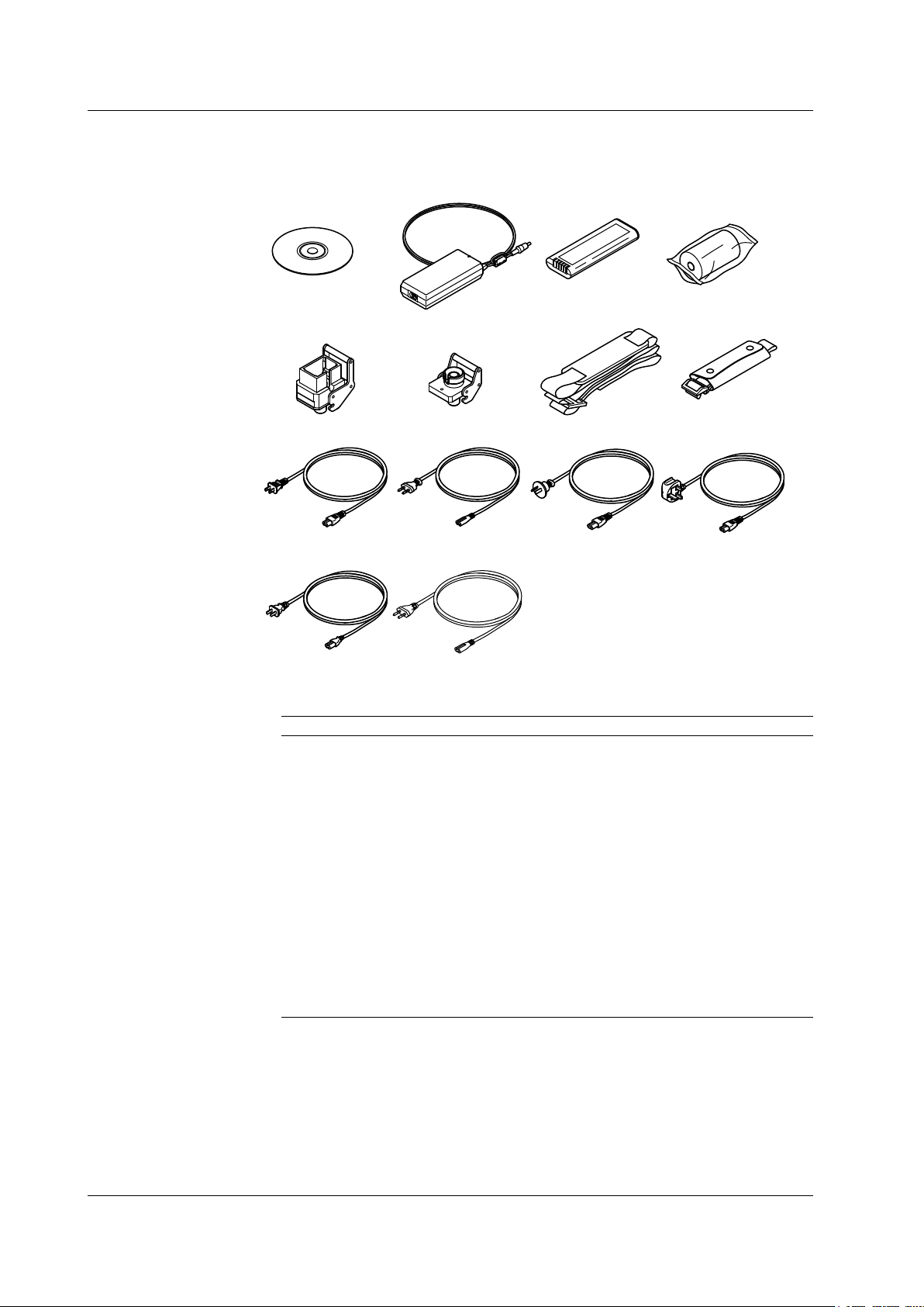
Power cord
UL/CSA St’d
A1068WD
*1 Included if the suffix code is /PL.
*2 Included if the suffix code is -USC.
*3 Included if the suffix code is -UFC.
*4 Included if the suffix code is /SB.
Power cord
VDE St’d
A1071WD
Power cord
AS St’d
A1070WD
Power cord
BS St’d
A1069WD
Power cord
GB St’d
A1076WD
AQ7270 Series OTDR
User’s Manual
B8070TH
AC adapter
739870-D/F/R/Q/H/P
Battery pack
739880
Printer roll paper
A9010ZP
*1
Universal connector
(SC)
SU2005A-SCC
*2
Universal connector
(FC)
SU2005A-FCC
*3
Hand belt
B8070CX
Shoulder belt
*4
B8070CY
Power cord
EK St’d
A1078WD
Checking the Contents of the Package
Standard Accessories
The standard accessories below are supplied with the instrument.
Optional Accessories (Sold Separately)
The optional accessories below are available for purchase separately.
Name Part Number Notes
Soft carrying case 738960 Soft case
Emulation software 735070 Waveform analysis application
Printer roll paper A9010ZP 80 mm width × 25 m roll: 10 rolls per
unit
Battery pack(reserve) 739880
External Large Capacity Battery 739881 Attached Connecting Cord and Battery
case
Universal adapter(SC) SU2005A-SCC SC type
Universal adapter(FC) SU2005A-FCC FC type
Shoulder belt B8070CY
AC adapter(reserve) 739870-D UL/CSA standard
739870-F VDE standard
739870-R AS standard
739870-Q BS standard
739870-H GB standard, Complied with CCC
739870-P EK standard
iv
IM 735020-01E
Page 7
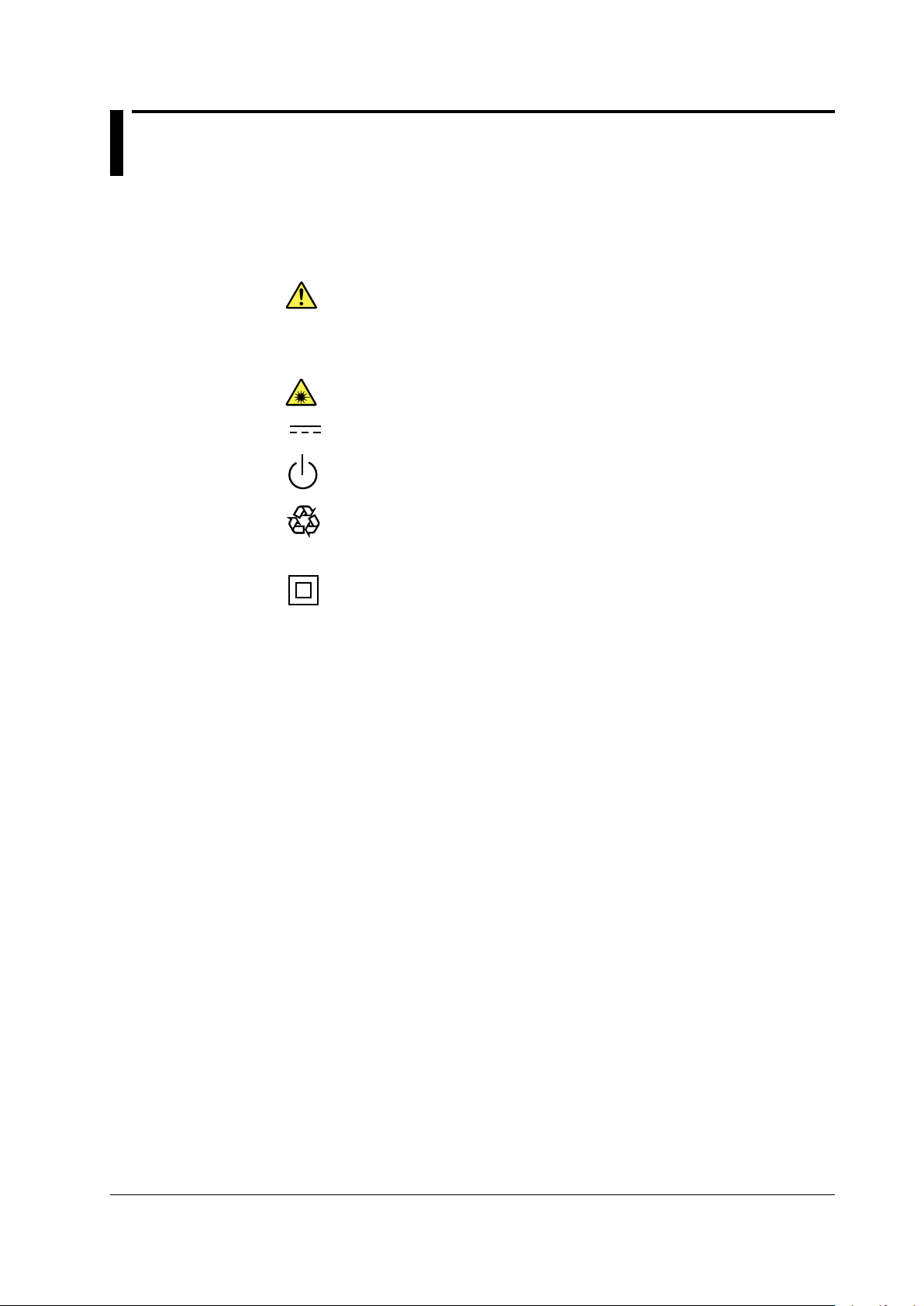
Safety Precautions
Ni-MH
To use the instrument safely and effectively, be sure to observe the precautions given in
the user’s manual.
The following symbols are used on this instrument.
Warning: handle with care. Refer to the user’s manual or service manual.
This symbol appears on dangerous locations on the instrument which require
special instructions for proper handling or use. The same symbol appears in the
corresponding place in the manual to identify those instructions.
Hazard, radiation of laser apparatus
Direct current
Stand-by (power)
Recycle
Double insulation mark (equipment protected throughout by double insulation or
reinforced insulation)
IM 735020-01E
v
Page 8

Safety Precautions
Make sure to comply with the precautions below. Not complying might result in
injury or death, or damage to the instrument.
WARNING
Use the Correct Power Supply
Before connecting the power cord, ensure that the source voltage matches the
rated supply voltage of the AC adapter and that it is within the maximum rated
voltage of the provided power cord.
Use the Correct Power Cord
Use only the power cord that comes with the instrument. Do not use it for other
devices.
Use the Correct AC Adapter
Use only the AC adapter specified for the instrument. Do not use it for other
devices.
Use Only the Designated Battery pack
Use only the battery pack specified for the instrument. Do not use it for other
devices.
Use only this instrument or a charger specified by YOKOGAWA to charge the
battery pack. If the fast charge does not finish after three hours or more, stop
charging the battery pack immediately.
Because the electrolyte solution inside the battery pack is alkaline, harm can be
done to the clothes or skin, if the battery pack leaks or explodes and the solution
comes in contact. If the electrolyte solution enters the eye, it can cause blindness.
In such cases, do not rub the eye. Rinse thoroughly with water and immediately
consult your eye doctor.
To prevent the possibility of electric shock and accidents, always turn OFF the
power switch and remove the AC adapter power supply from the instrument when
replacing the battery pack.
Do not throw the battery pack into fire or apply heat to it. This can cause dangerous
explosions or spraying of the electrolytes.
Do Not Look at the Laser Light
Do not look at the laser’s direct ray, reflected ray from a mirror, or indirect ray
without the proper protective eyewear. In addition, avoid being exposed to the laser
light. It can cause blindness or damage to the eye.
Do Not Operate in an Explosive Atmosphere
Do not use the thermocouple in a location where any flammable or explosive gas/
vapor is present. Operation in such an environment constitutes a safety hazard.
Do Not Remove Covers
The covers should be removed by YOKOGAWA’s qualified personnel only.
Opening the cover is dangerous, because some areas inside the instrument
have high voltages.
Carrying and Moving the Instrument
Remove all power cords and connection cables from the main unit before moving
the instrument. When carrying the instrument, hold it firmly by the handle.
Also, if storage media is inserted into the instrument, always remove the storage
media before carrying or moving the instrument. Never leave the media inserted
when carrying or moving. The storage media can become damaged.
Apply Correct Signals to the Optical Connectors (PORT1 and PORT2)
Do not apply light that is —5 dBm or greater to the AQ7270/AQ7275 optical
connectors (PORT1 and PORT2).
Doing so may damage the AQ7270/AQ7275.
vi
IM 735020-01E
Page 9

CAUTION
When Measuring with the Same Wavelength as the Communication Light
Most instrument models use the same wavelength for measurement as is
used for communication. If communication light is present in an optical fiber
being measured, this has an affect on the communication itself. Take sufficient
precautions to avoid interruption of communications. The measurements by the
instrument may also be incorrect, therefore the measuring environment (presence
or absence of communication light, etc.) should be carefully considered.
When Measuring with a Wavelength Different from the Communication Light
(1625/1650 nm)
When there is communication light in the fiber under test, use a wavelength
different from the communication light for measurement.
If no cutoff filter of 1625 nm or 1650 nm is installed in an instrument connected to
the system under test, or depending on the instrument’s lightfastness power rating
or characteristics of the cutoff filter such as its attenuation, the pulse light output
from the instrument can, in the worst case, damage the instrument. Check that an
appropriate cutoff filter is installed and that there is no problem with the instrument’
s ratings, then take sufficient caution during use.
Safety Precautions
When Using the Angled PC SC Connector (Suffix Code:-ASC)
•
Use the same type of angled PC SC connector for the connected optical fiber
cable as well.
The ferrule end of the angled PC SC connector is polished to an angle.
I
other types of connectors are used, the end face of the connector may become
f
damaged.
• You can replace the
AQ7270/AQ7275 connector, but only with an SC type.
See below for operating environment limitations.
CAUTION
This product is a Class A (for industrial environments) product. Operation of this
product in a residential area may cause radio interference in which case the user
will be required to correct the interference.
IM 735020-01E
vii
Page 10
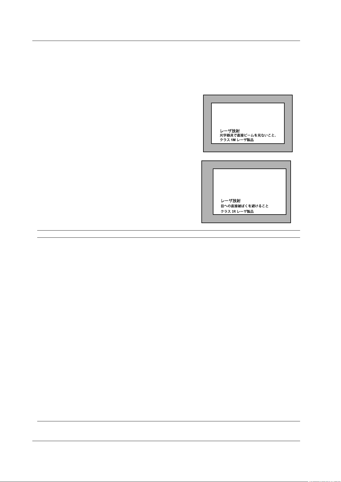
Safety Precautions
INVISIBLE LASER RADIATION
DO NOT VIEW DIRECTY WITH
OPTICAL INSTRUMENTS
CLASS 1M LASER PRODUCT
(IEC 60825-1:2007)
Laser Class 1M Label
If the laser output is observed at a distance of
100mm or less from the laser beam emitting
part by means of optical method (loupe,
magnifying glass, microscope, etc.), this may
cause eye injury.
VISIBLE LASER RADIATION
AVOID DIRECT EYE EXPOSURE
CLASS 3R LASER PRODUCT
(IEC 60825-1:2007)
MAX OUTPUT WAVELENGTH
5mW 650±20nm
Laser Class 3R Label
Avoid direct eye exposure
Safety Precautions for Laser Products
This instrument uses a laser light source. This instrument is a Class 1M laser product
as defined by IEC60825-1 Safety of Laser Products-Part 1: Equipment Classification,
Requirements and User’s Guide. In addition, the AQ7270/AQ7275 complies with
21 CFR 1040.10 except for the items that deviate from the standard as a result of
complying with Laser Notice No.50 dated on June 24, 2007.
MODEL Class Center Wavelength Output Power
735020 1M 1550nm CW: ≤5mW@1550nm
PULSE: ≤200mW@1550nm
PULSEwidth:≤20us@1550nm(dutycycle:≤2.5%)
735021 1M 1650nm CW: ≤5mW@1650nm
PULSE: ≤32mW@1650nm
PULSEwidth:≤20us@1650nm(dutycycle:≤2.5%)
735022 1M 1310/1550nm CW: ≤5mW@1310/1550nm
PULSE: ≤200mW@1310/1550nm
PULSEwidth:≤20us@1310/1550nm(dutycycle:≤2.5%)
735023 1M 1310/1550nm CW: ≤5mW@1310/1550nm
PULSE: ≤200mW@1310/1550nm
PULSEwidth:≤20us@1310/1550nm(dutycycle:≤2.5%)
735024 1M 1550/1625nm CW: ≤5mW@1550/1625nm
PULSE: ≤200mW@1550/1625nm
PULSEwidth:≤20us@1550/1625nm(dutycycle:≤2.5%)
735025 1M 1310/1490/1550nm CW: ≤5mW@1310/1490/1550nm
PULSE: ≤200mW@1310/1490/1550nm
PULSEwidth:≤20us@1310/1490/1550nm(dutycycle:≤2.5%)
735026 1M 1310/1550/1625nm CW: ≤5mW@1310/1550/1625nm
PULSE: ≤200mW@1310/1550/1625nm
PULSEwidth:≤20us@1310/1550/1625nm(dutycycle:≤2.5%)
735027 1M 1310/1550/1650nm CW: ≤5mW@1310/1550/1650nm
PULSE: ≤200mW@1310/1550nm
PULSE: ≤32mW@1650nm
PULSEwidth:≤20us@1310/1550/1650nm(dutycycle:≤2.5%)
735028 1M 1310/1550/1625nm CW: ≤5mW@1310/1550/1625nm
PULSE: ≤200mW@1310/1550/1625nm
PULSEwidth:≤20us@1310/1550/1625nm(dutycycle:≤2.5%)
viii
IM 735020-01E
Page 11

Safety Precautions
MODEL Class Center Wavelength Output Power
735029 1M 850/1300nm PULSE: ≤50mW@850nm
≤100mW@1300nm
PULSEwidth:≤1us@850nm(dutycycle:≤5%)
≤5us@1300nm(dutycycle:≤0.6%)
735030 1M 850/1300nm PULSE: ≤50mW@850nm
≤100mW@1300nm
PULSEwidth:≤1us@850nm(dutycycle:≤5%)
≤5us@1300nm(dutycycle:≤0.6%)
1310/1550nm CW: ≤5mW@1310/1550nm
PULSE: ≤200mW@1310/1550nm
PULSEwidth:≤20us@1310/1550nm(dutycycle:≤2.5%)
735031 1M 1650nm CW: ≤5mW@1650nm
PULSE: ≤32mW@1650nm
PULSEwidth:≤20us@1650nm(dutycycle:≤2.5%)
3R 650nm CW: ≤5mW@650nm
735032 1M 1310/1550nm CW: ≤5mW@1310/1550nm
PULSE: ≤200mW@1310/1550nm
PULSEwidth:≤20us@1310/1550nm(dutycycle:≤2.5%)
3R 650nm CW: ≤5mW@650nm
735033 1M 1310/1550nm CW: ≤5mW@1310/1550nm
PULSE: ≤200mW@1310/1550nm
PULSEwidth:≤20us@1310/1550nm(dutycycle:≤2.5%)
3R 650nm CW: ≤5mW@650nm
735034 1M 1310/1550nm CW: ≤5mW@1310/1550nm
PULSE: ≤200mW@1310/1550nm
PULSEwidth:≤20us@1310/1550nm(dutycycle:≤2.5%)
3R 650nm CW: ≤5mW@650nm
735035 1M 1310/1490/1550nm CW: ≤5mW@1310/1490/1550nm
PULSE: ≤200mW@1310/1490/1550nm
PULSEwidth:≤20us@1310/1490/1550nm(dutycycle:≤2.5%)
3R 650nm CW: ≤5mW@650nm
735036 1M 1310/1550/1625nm CW: ≤5mW@1310/1550/1625nm
PULSE: ≤200mW@1310/1550/1625nm
PULSEwidth:≤20us@1310/1550/1625nm(dutycycle:≤2.5%)
735037 1M 1310/1550/1650nm CW: ≤5mW@1310/1550/1650nm
PULSE: ≤200mW@1310/1550nm
PULSE: ≤32mW@1650nm
PULSEwidth:≤20us@1310/1550/1650nm(dutycycle:≤2.5%)
735038 1M 1310/1550/1625nm CW: ≤5mW@1310/1550/1625nm
PULSE: ≤200mW@1310/1550/1625nm
PULSEwidth:≤20us@1310/1550/1625nm(dutycycle:≤2.5%)
3R 650nm CW: ≤5mW@650nm
735040 1M 850/1300nm PULSE: ≤50mW@850nm,PULSE:≤100mW@1300nm
PULSEwidth:≤1us@850nm(dutycycle:≤5%)
≤5us@1300nm(dutycycle:≤0.6%)
1310/1550nm CW: ≤5mW@1310/1550nm
PULSE: ≤200mW@1310/1550nm
PULSEwidth:≤20us@1310/1550nm(dutycycle:≤2.5%)
735041 1M 850/1300nm PULSE: ≤50mW@850nm,PULSE:≤100mW@1300nm
PULSEwidth:≤1us@850nm(dutycycle:≤5%)
≤5us@1300nm(dutycycle:≤0.6%)
1310/1550nm CW: ≤5mW@1310/1550nm
PULSE: ≤200mW@1310/1550nm
PULSEwidth:≤20us@1310/1550nm(dutycycle:≤2.5%)
IM 735020-01E
If the instrument is used in a manner not specified in this manual, the protection provided
by the instrument may be impaired. Yokogawa Electric Corporation assumes no liability
for the customer’s failure to comply with these requirements.
ix
Page 12

Waste Electrical and Electronic Equipment
Waste Electrical and Electronic Equipment (WEEE), Directive 2002/96/EC
(This directive is only valid in the EU.)
This product complies with the WEEE Directive (2002/96/EC) marking
requirement. This marking indicates that you must not discard this electrical/
electronic product in domestic household waste.
Product Category
With reference to the equipment types in the WEEE directive Annex 1, this
product is classified as a “Monitoring and Control instrumentation” product.
Do not
dispose in domestic household waste. When disposing products in the EU,
contact your local Yokogawa Europe B. V. office.
x
IM 735020-01E
Page 13

Symbols and Notation Used in This Manual
Safety Markings
The following markings are used in this manual.
Improper handling or use can lead to injury to the user or damage
to the instrument. This symbol appears on the instrument to indicate
that the user must refer to the users manual for special instructions.
The same symbol appears in the corresponding place in the user’
s manual to identify those instructions. In the manual, the symbol is
used in conjunction with the word “WARNING” or “CAUTION.”
WARNING
CAUTION
Calls attention to information that is important for proper operation of
Note
Calls attention to actions or conditions that could cause serious or
fatal injury to the user, and precautions that can be taken to prevent
such occurrences.
Calls attention to actions or conditions that could cause light injury
to the user or damage to the instrument or the user’s data, and
precautions that can be taken to prevent such occurrences.
the instrument.
Notations Used on Pages Describing Operating Procedures
On pages that describe the operating procedures in chapters 4 through 19, the following
displayed characters, and terminology are used to distinguish the procedures from their
explanations.
Procedure
Explanation
Carry out the procedure according to the step numbers. All
procedures are written with inexperienced users in mind; experienced
users may not need to carry out all the steps.
This section describes the setup items and the limitations regarding
the procedures. It may not give a detailed explanation of the function.
For a detailed explanation of the function, see chapter 2.
Unit
IM 735020-01E
Displayed Characters and Terminology Used in the Procedural
Explanations
Panel Keys and Soft keys
Bold characters used in the procedural explanations indicate characters that are marked on the
panel keys or the characters of the soft keys or menus displayed on the screen.
k Denotes 1000. Example: 12 kg, 100 kHz
xi
Page 14

Contents
Checking the Contents of the Package.............................................................................................ii
Safety Precautions ............................................................................................................................v
Waste Electrical and Electronic Equipment ......................................................................................x
Symbols and Notation Used in This Manual ....................................................................................xi
Chapter 1 Names and Functions of Parts
1.1 Front Panel ....................................................................................................................... 1-1
1.2 Rear Panel ....................................................................................................................... 1-2
1.3 Side Panel ........................................................................................................................
1.4 Display ..............................................................................................................................
Chapter 2 Measurement Overview
2.1 MeasurementConguration ............................................................................................. 2-1
2.2 Measurement Procedure .................................................................................................. 2-4
2.3 Viewing the Optical Pulse Measurement W
2.4 Distance Measurement ...................................................................................................2-11
Chapter 3 Measurement Preparation
3.1 Connecting the Power Supply .......................................................................................... 3-1
3.2 Connecting the Optical Fiber Cable ................................................................................. 3-5
3.3 Setting the Date and T
3.4 Loading the Printer Roll Paper (Option) ........................................................................... 3-9
3.5 Connecting the USB Interface ........................................................................................ 3-10
3.6 Connecting the Ethernet Interface (Option) .....................................................................3-1
3.7 Attaching the Belt ........................................................................................................... 3-12
ime ................................................................................................ 3-7
1-3
1-5
aveform ........................................................ 2-9
1
Chapter 4 Setting the Optical Pulse Measurement Conditions (Simple Full Auto
Mode)
4.1 Selecting the Test Wavelength ......................................................................................... 4-1
4.2 Selecting the Approximation Method ................................................................................ 4-3
4.3 Setting Other Items ......................................................................................................
.... 4-4
Chapter 5 Setting the Optical Pulse Measurement Conditions (Measurement
Wizard Mode)
5.1 Setting the Measurement Conditions ............................................................................... 5-1
5.2 Setting the Analysis Conditions ........................................................................................ 5-8
5.3 Setting
5.4 Setting the File ......................................................................................................
theDetectionConditionsofReectionandLossWaveforms .............................5-11
......... 5-16
Chapter 6 Setting the Optical Pulse Measurement Conditions (Detail Mode
(Manually Setting All Items))
6.1 Setting the Measurement Conditions ............................................................................... 6-1
6.2 Setting the Analysis Conditions ...................................................................................... 6-16
6.3 Setting the Multi Wavelength Measurement Conditions .................................................
6.4 Setting the Multi Wavelength
Analysis Conditions .......................................................... 6-25
6-22
xii
IM 735020-01E
Page 15

Contents
Index
App
21
20
19
18
17
16
15
14
13
12
11
10
9
8
7
6
5
4
3
2
1
Chapter 7 Executing the Optical Pulse Measurement (Acquiring Waveforms)
7.1 Realtime Measurement .................................................................................................... 7-1
7.2 Averaging Measurement .................................................................................................. 7-5
7.3 Displaying the Measurement Conditions .......................................................................... 7-7
7.4 High Resolution Measurement of the Selected Location ................................................. 7-8
7.5 Measuring Multicore Fiber ...............................................................................................7-11
7.6 Warm-up Measurement .................................................................................................. 7-28
Chapter 8 Zooming the Waveform
8.1 Zooming the Display ......................................................................................................... 8-1
8.2 Moving the Waveform ....................................................................................................... 8-2
8.3 Initializing the Waveform Display ......................................................................................
8.4 Auto Zoom the Waveform Display ....................................................................................
8-3
8-4
Chapter 9 Macro Measurement
9.1 CreatingtheMeasurementConditions(DeningtheMacroConditions) ......................... 9-1
9.2 Saving the Macro Measurement Results ......................................................................... 9-3
9.3 Loading the Measurement Conditions .............................................................................. 9-9
9.4 Executing the Macro .......................................................................................................
9.5 Saving/Loading Macro Conditions .................................................................................. 9-13
Chapter 10 Measuring the Distance
10.1 Marker and Cursor Operation ......................................................................................... 10-1
10.2 Measuring the Distance .................................................................................................. 10-9
10.3 Moving the Measurement Reference ........................................................................... 10-12
Chapter 11 Measuring the Splice and Return Loss
11.1 Measuring the Splice Loss ..............................................................................................11-1
11.2 Measurement Taking the Adjacent Splice Loss into Consideration .................................11-7
11.3 Measuring
theReturnLossandReectionLevel ............................................................11-9
Chapter 12 Editing the Event List
12.1 Viewing the Measured Results ....................................................................................... 12-1
12.2 Editing the Waveform ..................................................................................................... 12-3
12.3 Editing the List ..............................................................................................................
Chapter 13 Detail Analysis of the Measured Waveform
13.1 Displaying the Multiple Waveforms ................................................................................ 13-1
13.2 2-Way Trace ................................................................................................................... 13-4
13.3 Difference W
13.4 Section Analysis ......................................................................................................
13.5 Fixing the Waveform
aveform ...................................................................................................... 13-9
..................................................................................................... 13-14
Chapter 14 Optical Power Monitoring (Option)
14.1 Calibration before the Measurement .............................................................................. 14-1
14.2 Setting the Reference ..................................................................................................... 14-2
14.3 Selecting the Display Unit .............................................................................................. 14-3
14.4 Selecting the W
14.5 Setting the Offset .......................................................................................................
14.6 Set the Threshold Level
avelength ...............................................................................................
.................................................................................................. 14-6
9-11
.
12-14
..... 13-12
14-4
..... 14-5
IM 735020-01E
xiii
Page 16

Contents
Chapter 15 Light Source Operation (Option)
15.1 Light and Stabilized Light Source ................................................................................... 15-1
15.2 Visible Light Source ........................................................................................................ 15-3
Chapter 16 Checking Fiber End Faces
16.1 Using Fiber Inspection Probes to View the Status of Optional Fiber End Faces. .......... 16-1
Chapter 17 Multi Core Trace Comparison
17.1 Measuring Optical Pulses before Work and after Work .................................................. 17-1
17.2 ConguringtheCoreInformation ................................................................................. 17-10
17.3 Setting Measurement Conditions ................................................................................. 17-15
17.4 Setting
Analysis Conditions ..........................................................................................
Chapter 18 Saving, Loading, and Printing Files
18.1 Loading and Saving Files ............................................................................................... 18-1
18.2 Deleting or Copying the Files ......................................................................................... 18-8
18.3 Renaming the File ........................................................................................................
18.4 Creating, Deleting, and Copying Folders ..................................................................... 18-14
18.5 Printing ......................................................................................................
18.6 Entering Characters ..................................................................................................... 18-21
18.7 Creating Labels ......................................................................................................
18.8 Initializing (formatting) the internal memory ................................................................. 18-29
...................
......
17-16
18-12
18-18
18-23
Chapter 19 Other Settings
19.1 Setting the System ......................................................................................................... 19-1
19.2 Setting the Display ......................................................................................................... 19-9
19.3 Setting the Network (/PL Option)
19.4 Network File T
19.5 Cable
InstallationCompletionNotication .................................................................... 19-23
ransfers ................................................................................................. 19-22
.................................................................................. 19-18
Chapter 20 Troubleshooting, Maintenance, and Inspection
20.1 Troubleshooting .............................................................................................................. 20-1
20.2 Error Messages .............................................................................................................. 20-2
20.3 Self T
20.4 Updating the Firmware ................................................................................................... 20-8
20.5 Mechanical Inspection .................................................................................................. 20-10
20.6 Checking the Operation .................................................................................................20-1
20.7 Replacing the Battery Pack ..........................................................................................
20.8 Replacing the Optical
20.9 Routine Maintenance ................................................................................................... 20-17
20.10 Storage Precautions ..................................................................................................... 20-18
20.11
Recommended Replacement Parts .............................................................................
20.12 Calibration ....................................................................................................................
est .......................................................................................................................... 20-7
Adapter
...................................................................................... 20-15
Chapter 21 Specications
21.1 Models ............................................................................................................................ 21-1
21.2 Optical Section ............................................................................................................... 21-2
21.3 General
21.4 External Dimensions .................................................................................................... 21-10
Specications ................................................................................................... 21-8
1
20-12
20-19
20-20
xiv
IM 735020-01E
Page 17

Appendix
Index
App
21
20
19
18
17
16
15
14
13
12
11
10
9
8
7
6
5
4
3
2
1
Contents
Appendix 1 Terminology ........................................................................................................ App-1
Appendix 2 Key Assignments for the USB104 Keyboard ......................................................App-6
Appendix3
Exampleofleinput/output ................................................................................ App-7
Index
IM 735020-01E
xv
Page 18
1
OPTICAL INPUT
MENU
F 1
F 2
F 3
F 4
F 5
ESC
FILE
SCALE
ENTER
SETUP
REAL
TIME
AVG
CHARGE
ON
1
2 3
4
5 6
7
8
9
10
11
12
13
14
15
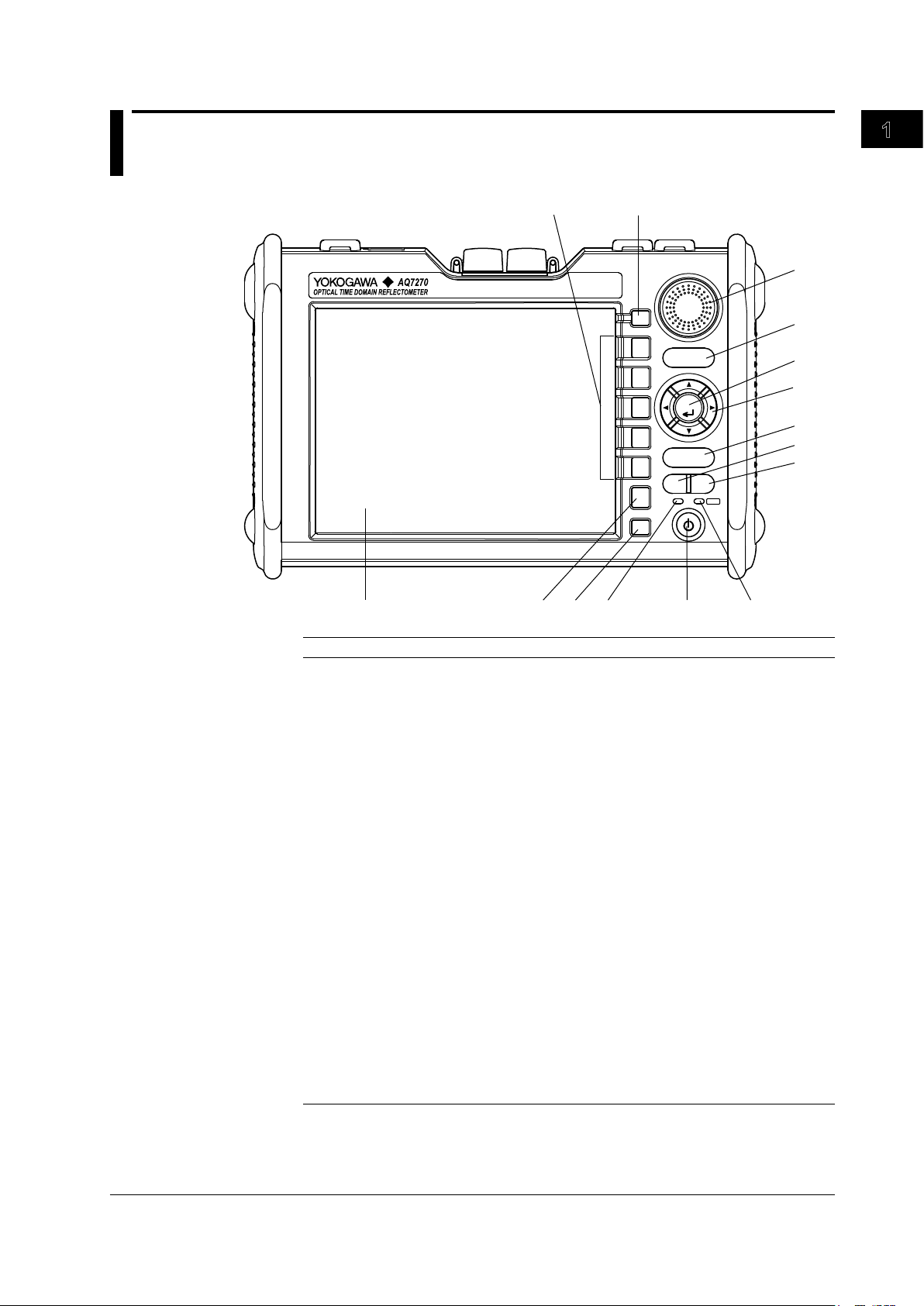
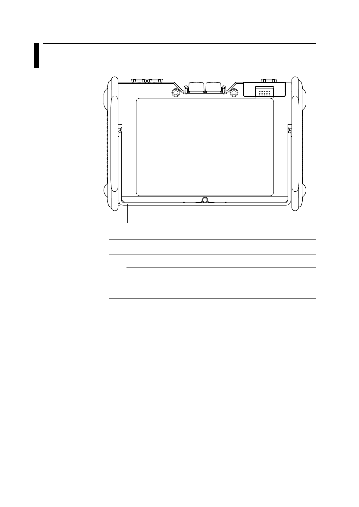
Chapter 1 Names and Functions of Parts
1.1 Front Panel
Names and Functions of Parts
IM 735020-01E
Number Name Function
1 LCD Displays the measured waveforms, measurement
conditions, etc.
2 ESC key Cancels an operation or returns to the previous display.
3 FILE key Operate files and print waveforms.
Some also used as soft keys.
4 CHARGE lamp Lights (green) while the battery pack is fast charging.
Turns OFF when the battery pack is finished fast charging.
Blinks (green) if the battery pack cannot be fast charged.
5 POWER switch Turns the instrument on/off
6 POWER lamp Illuminates while the instrument is turned on (green).
When the battery level is low (red).
7 AVERAGE key Starts or stop the averaging measurement.
8 REALTIME key Starts or stop the realtime measurement.
9 SETUP key Sets measurement conditions and system configuration.
Also used to change the event detection conditions for
event analysis.
Arrow keys Moves, expands, and reduces waveforms, moves cursors,
10
etc.
11 ENTER key Confirms the operation
12 SCALE key Expands, reduces, and moves waveforms.
13 Rotary knob Moves cursors and markers, sets values, etc.
14 MENU key Returns to the initial screen at startup.
(Selects OTDR, optical power monitor, light source, and
one-button measurement.)
15 Soft keys Executes functions that are assigned to the soft keys
displayed at the right edge of the LCD.
1-1
Page 19
1.2 Rear Panel
1
Number Name Function
1 Stand Tilts the instrument.
Note
• The /PL option does not come with a stand.
• Do not use the stand as a handle to carry the AQ7270/AQ7275.
• Use the stand only to tilt the AQ7270/AQ7275.
• If you are tilting the AQ7270/AQ7275, check that the stand is fixed in place.
1-2
IM 735020-01E
Page 20
1
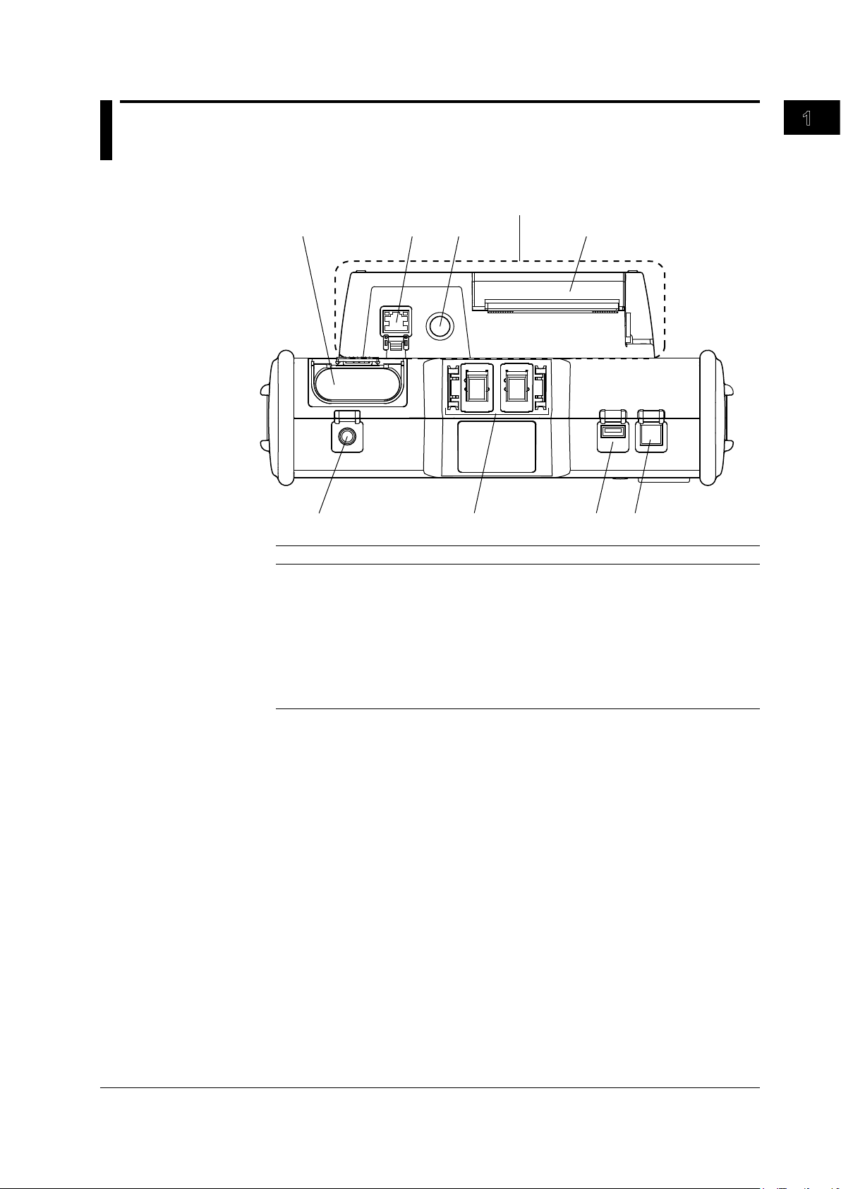
1.3 Side Panel
1
2
3
4
5
6
78
/PL Option
Top View
Names and Functions of Parts
Number Name Function
1 DC power connector Connects the AC adapter.
2 Optical connector Connects the optical fiber cable. *1
3 USB 1.1 connector (Type A) Connects a USB memory, USB printer,
the USB104 keyboard etc.
4 USB 1.1 connector (Type B)
5 Internal printer Prints waveforms and event lists.(/PL option)
6 Printer paper feed button Feeds the paper.(/PL option)
7 Ethernet connector Used for remote control.(/PL option)
8 Battery pack storage Stores the battery pack.
*1 The /PM option supports only PORT1. PORT2 (MMF) and 1650-nm wavelength are not
supported.
Used for remote control, storage, etc.
IM 735020-01E
1-3
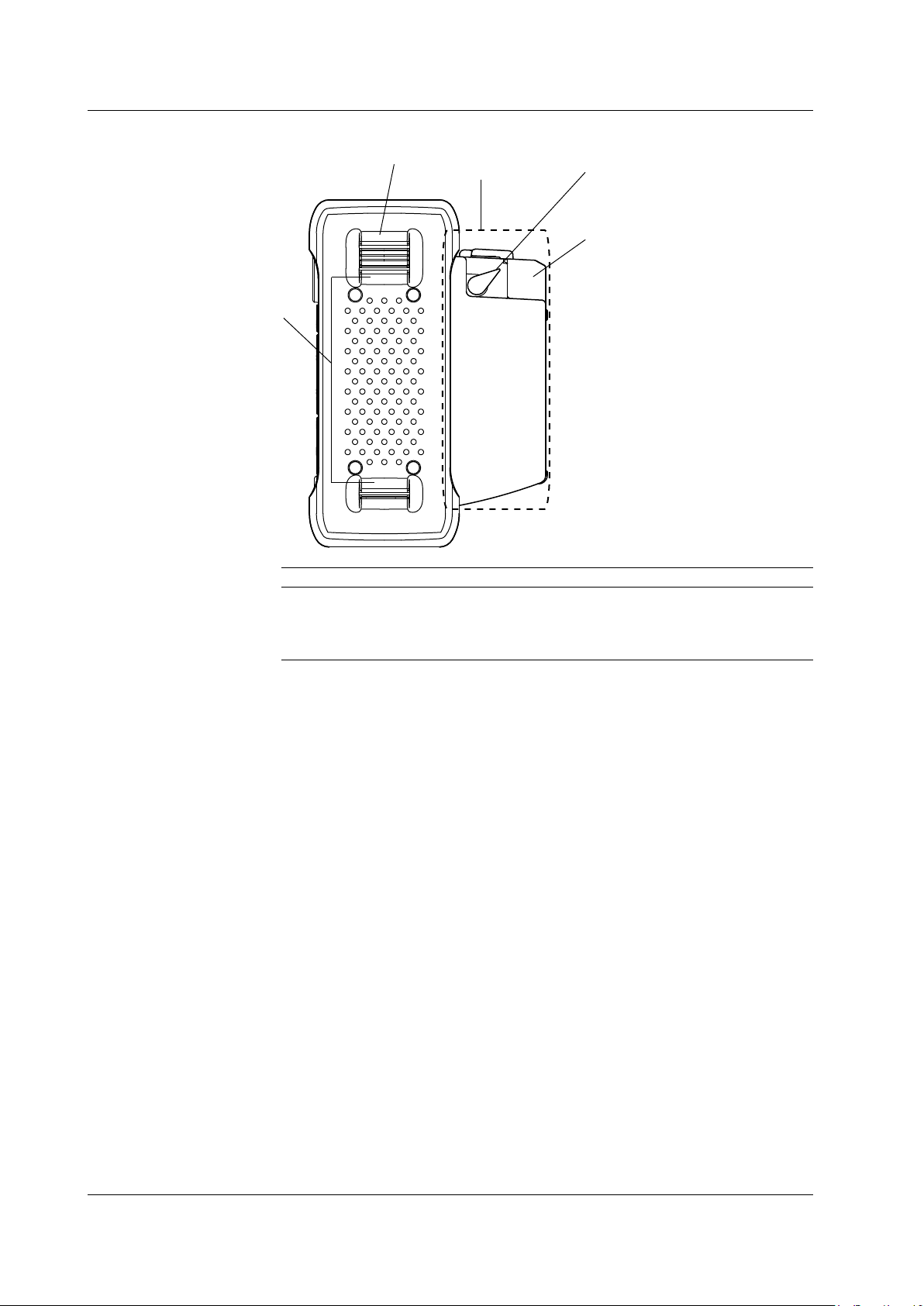
Page 21
1
2
3
4
/PL option
1.3 Side Panel
Right View
Number Name Function
1 Printer cover Stores the paper.
2 Lock lever Fixes the printer cover in place.
3 Shoulder belt bracket Attaches the shoulder belt.
4 Hand belt bracket Attaches the hand belt.
1-4
IM 735020-01E
Page 22
1
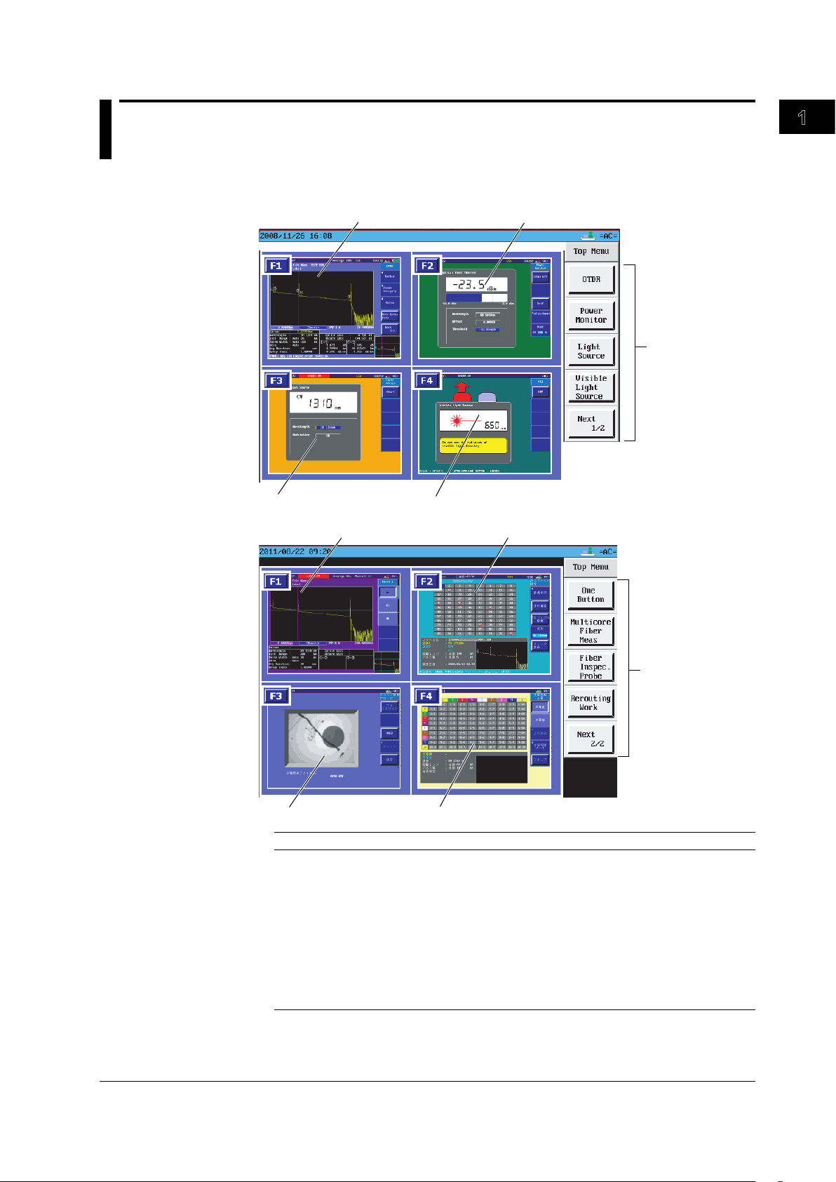
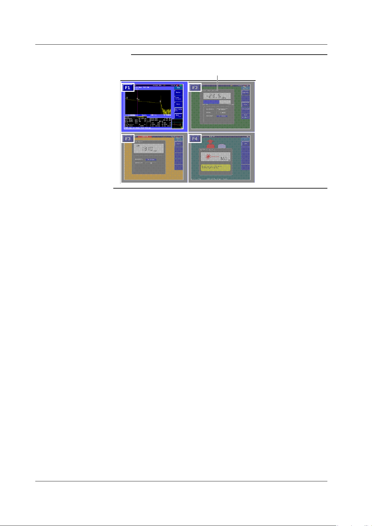
1.4 Display
1
2
3
4
5
5
6
7
8
9
Top Menu
Names and Functions of Parts
Number Function
1 Optical pulse measurement (OTDR) screen.
2 Optical power monitor screen (/PM option).
3 Light source screen (/LS /SLS option).
4 Visible Light source screen (/VLS option).
5 Displays the soft key menu.
6 One-button measurement screen.
7 multicore fiber measurement (
8 Displays the fiber inspection probe screen.
Displays the Multi Core Trace Comparison (main view) screen (firmware versions 3.01
9
and later).
main view display) screen.
IM 735020-01E
1-5
Page 23
A shaded area
1.4 Display
Note
Displays a shaded area when the option is not installed (firmware version 3.01 or later).
1-6
IM 735020-01E
Page 24
1
1
2
3
4
5
6
7
8
9
10
11
12
13
14
1516 17
18
19
20
21
22
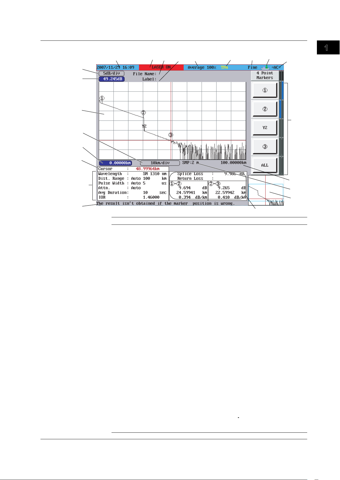
1.4 Display
Optical Pulse Measurement (OTDR)
Names and Functions of Parts
Number Function
1 Displays the value per scale mark on the vertical axis.
2 Shows the display start level of the vertical axis (top edge of the waveform display area)
3 Waveform display area
4 Displays the value per scale mark on the horizontal axis.
5 Shows the display start distance of the horizontal axis (left edge of the waveform display
area)
6 Displays the distance from the measurement reference point of the horizontal axis to the
cursor position.
7 Displays the measurement conditions.
8 Displays an explanation of the function
9 Displays the computed result of the measured data.
10 Displays the full screen of the waveform display area. The section displayed in the
waveform display area is indicated with a frame (overview).When adjusting the scale
using Zoom or Shift, the color of the frame is different. When you press Shift, the word
“SHIFT” is displayed at the upper right of the overview screen.
11 Displays the sampling resolution.
12
Shows the display end distance of the horizontal axis (right edge of the waveform
display area)
13 Displays the soft key menu.
14 Displays the type of power in use (battery pack or AC adapter)
15 Displays the cursor movement setting.
16 Displays the approximation method.
17 Displays in red the connector in which the optical pulse is output.
18 Displays the progress of the averaging measurement (AVE).Displays a bar graph
indicating the progress in the
19 Label area. The name of the next file to be saved blinks if auto save is turned ON.
20 Displays the operating status of the instrument.
While the optical pulse output is ON: “LASER ON” is indicated and the text ckground
blinks.
While the optical pulse output is OFF: Operation mode (Simple (Full Auto),
measurement Wizard, Detail, or Multi WL)
21 Displays the year, month, day, and time.
22 FILE name area
text background.
IM 735020-01E
1-7
Page 25
1 2
3
4
1 2
3
1.4 Display
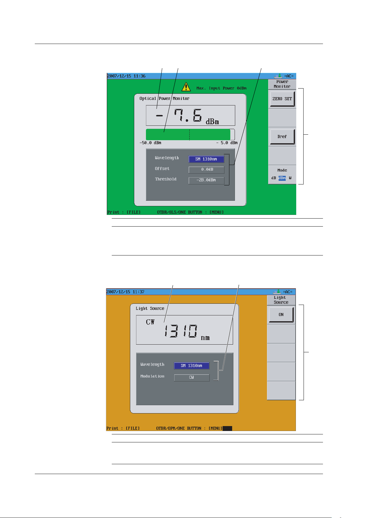
Optical Power Monitor(/PM option)
Number Function
1 Displays numerically the optical input power value.
2 Displays a graph of the optical input power value.
3 Measurement condition display area
4 Soft key menu
Light Source(/LS, /SLS option)
1-8
Number Function
1 Displays the wavelength value.
2 Measurement condition display area
3 Soft key menu
IM 735020-01E
Page 26
1
1
2
1
2
1.4 Display
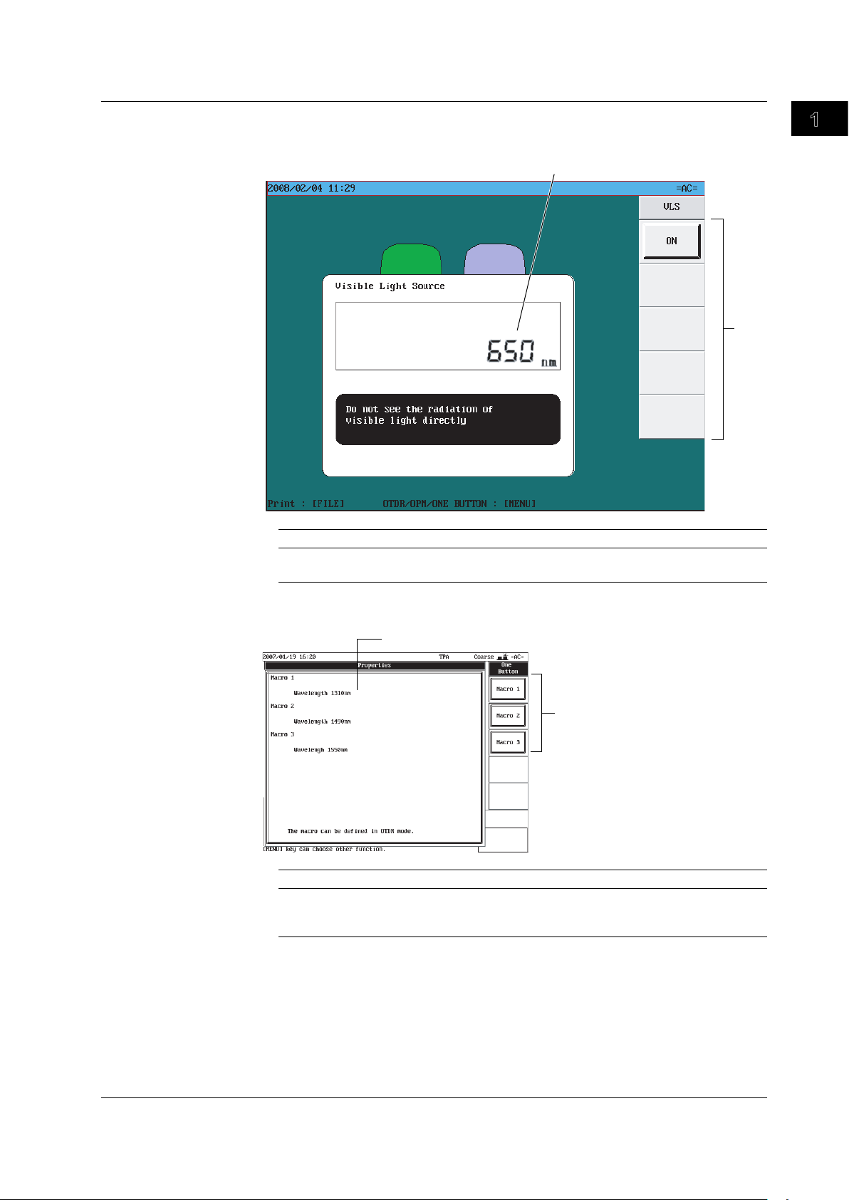
Visible Light source (/VLS option)
Number Function
1 Displays the wavelength value.
2 Soft key menu
Names and Functions of Parts
One-Button Measurement
Number Function
1 Displays the contents of the macro that is being defined (used to enter the macro while
viewing the contents).
2 Soft key menu
IM 735020-01E
1-9
Page 27
1
2
1
2
3
4
1.4 Display
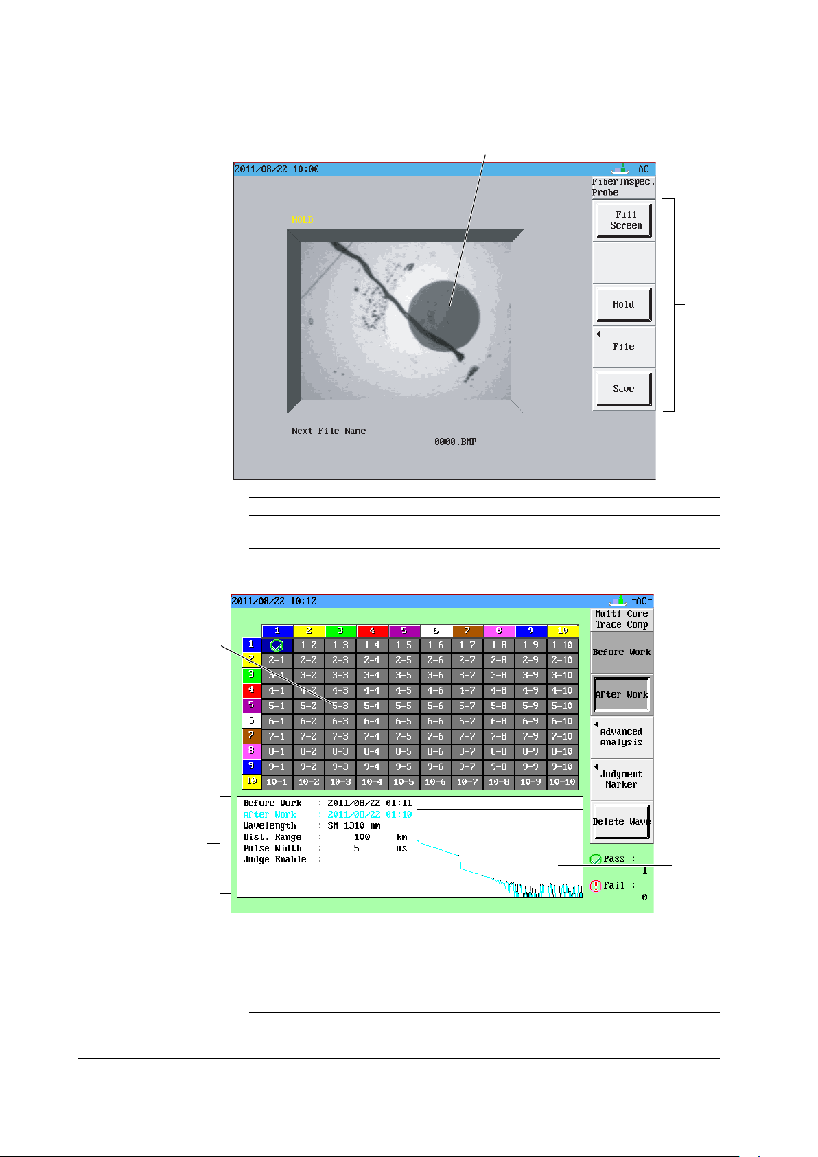
Fiber Inspection Probe
Number Function
1 Displays the fiber inspection probe screen.
2 Soft key menu
Multi Core Trace Comparison (Firmware Versions 3.01 and Later)
Number Function
1 Displays the number of the core of the optical fiber cable under measurement.
2 Displays the soft key menu.
3 Displays the information of the cell that the cursor is at.
4 Displays the waveform before work and the waveform after work at the same time.
1-10
IM 735020-01E
Page 28
2
1
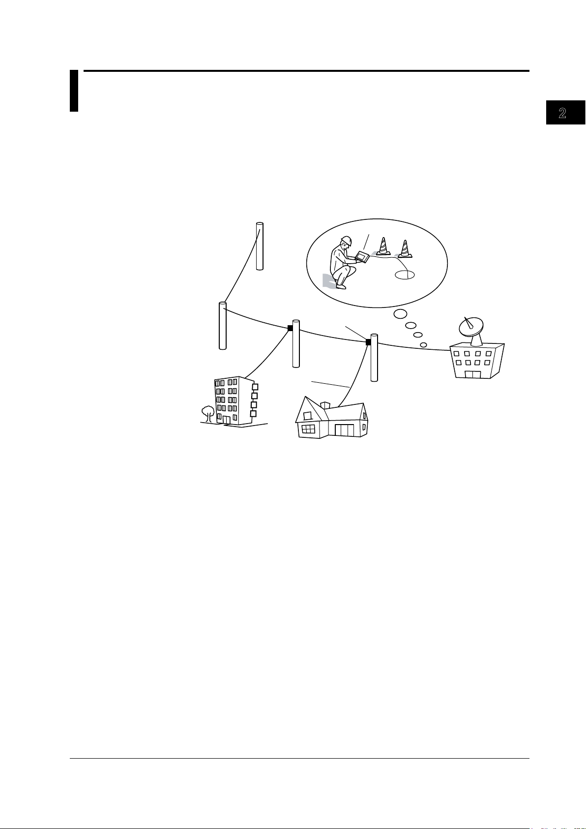
Telephone
pole
Closure
Optical fiber cable
Telephone
exchanges
Measurement in
cable installations
AQ7270/AQ7275 OTDR
Consumer
Corporate user
Chapter 2
Measurement Overview
2.1 Measurement Configuration
Overview of the AQ7270/AQ7275
The AQ7270/AQ7275 is an optical time domain reflectometer that measures optical
fiber lengths and losses and identifies failure locations. It is mainly used in the optical
fiber installation and maintenance servicing of access networks (communications links
between telephone exchanges and telephone poles) and user networks (communications
links between user sites and telephone poles). The light source and optical power
monitor functions can also be used as options.
Measurement Overview
Analysis Using the Emulation Software
The waveform data that is measured by the AQ7270/AQ7275 can be analyzed on your
PC using the AQ7932 OTDR emulation software (version 3.0 or later). The software
comes with a report creation wizard that is convenient in creating construction reports.
Precautions for Measurement
When Measuring with the Same Wavelength as the Communication Light
Most instrument models use the same wavelength for measurement as is used for
communication. If communication light is present in an optical fiber being measured, this
has an affect on the communication itself. Take sufficient precautions to avoid interruption
of communications. The measurements by the instrument may also be incorrect,
therefore the measuring environment (presence or absence of communication light, etc.)
should be carefully considered. For details on fiber-in-use alarm function, see section 6.1.
When Measuring with a Wavelength Different from Communication Light
(1625/1650 nm)
When there is communication light in the fiber under test, use a wavelength different from
the communication light for measurement.
IM 735020-01E
The instrument is designed to allow measurement that impacts communication as
little as possible in such cases, but be sure to install a cutoff filter of 1625 nm or 1650
nm in system under test. If measurements are taken without a cutoff filter installed,
communications can be affected and measurements may not be correct. Always check
the configuration of the system under test before use (presence or absence of an
appropriate cutoff filter, attenuation characteristics, etc.).
2-1
Page 29
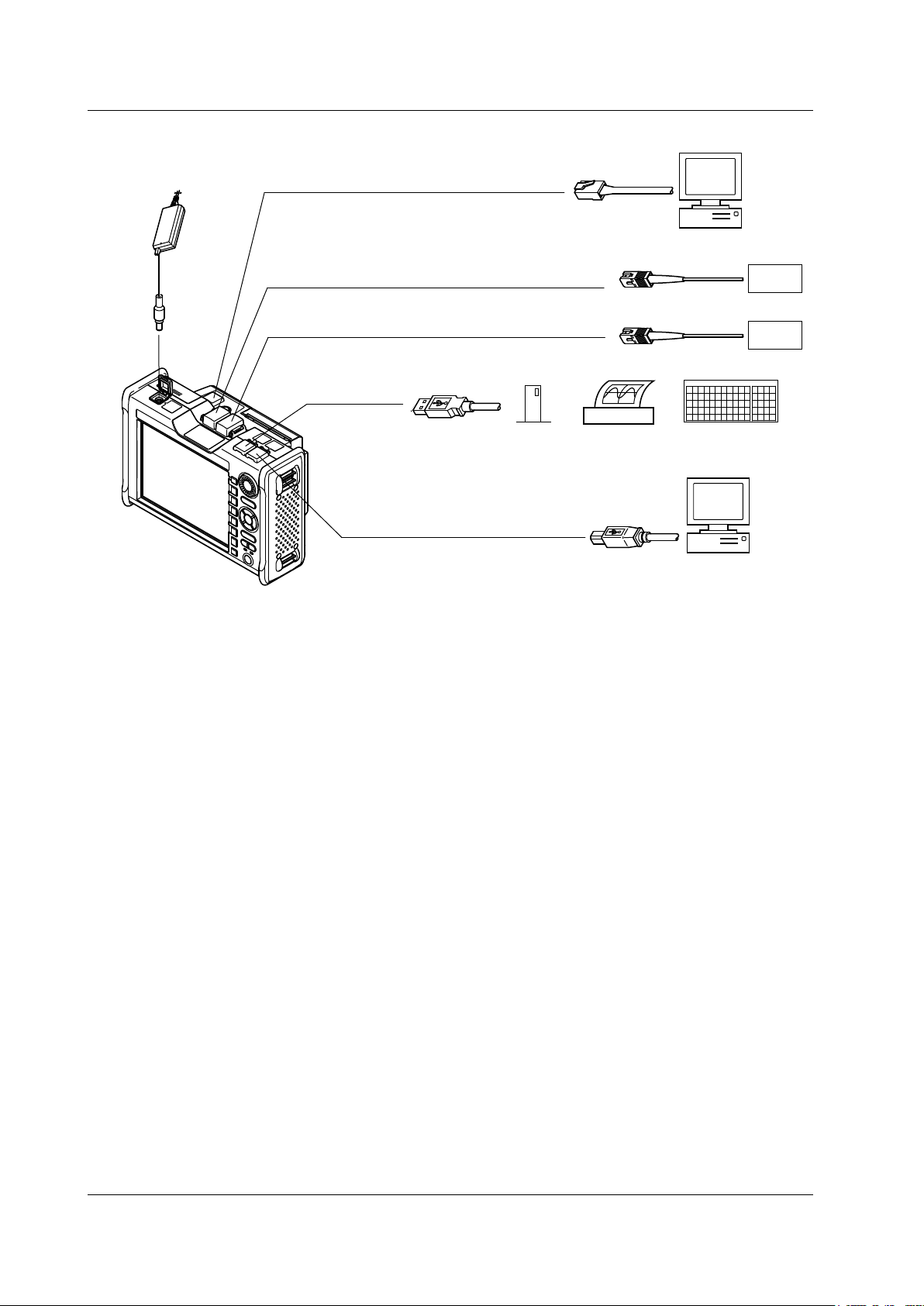
Ethernet connector (remote control)
PC
PC
USB connector
(remote control and storage)
USB printer
USB connector
USB memory
DUT
Optical connector PORT2
(wavelength *1: 650 nm, 850 nm, 1300 nm, and 1650 nm)
Optical connector PORT1
(wavelength *2: 1310 nm, 1490 nm, 1550 nm, and 1625 nm)
DUT
AC adapter
The 735021 and 735031 output 1650 nm from PORT1. The 735029 outputs 850 nm and 1300 nm from PORT1.
The /PM option supports only PORT1. PORT2 (MMF) and 1650-nm wavelength are not supported.
*1
USB104 keyboard
The 735036 outputs 1650 nm from PORT2.
*2
2.1 Measurement Configuration
Configuration of Peripheral Devices
2-2
IM 735020-01E
Page 30
2
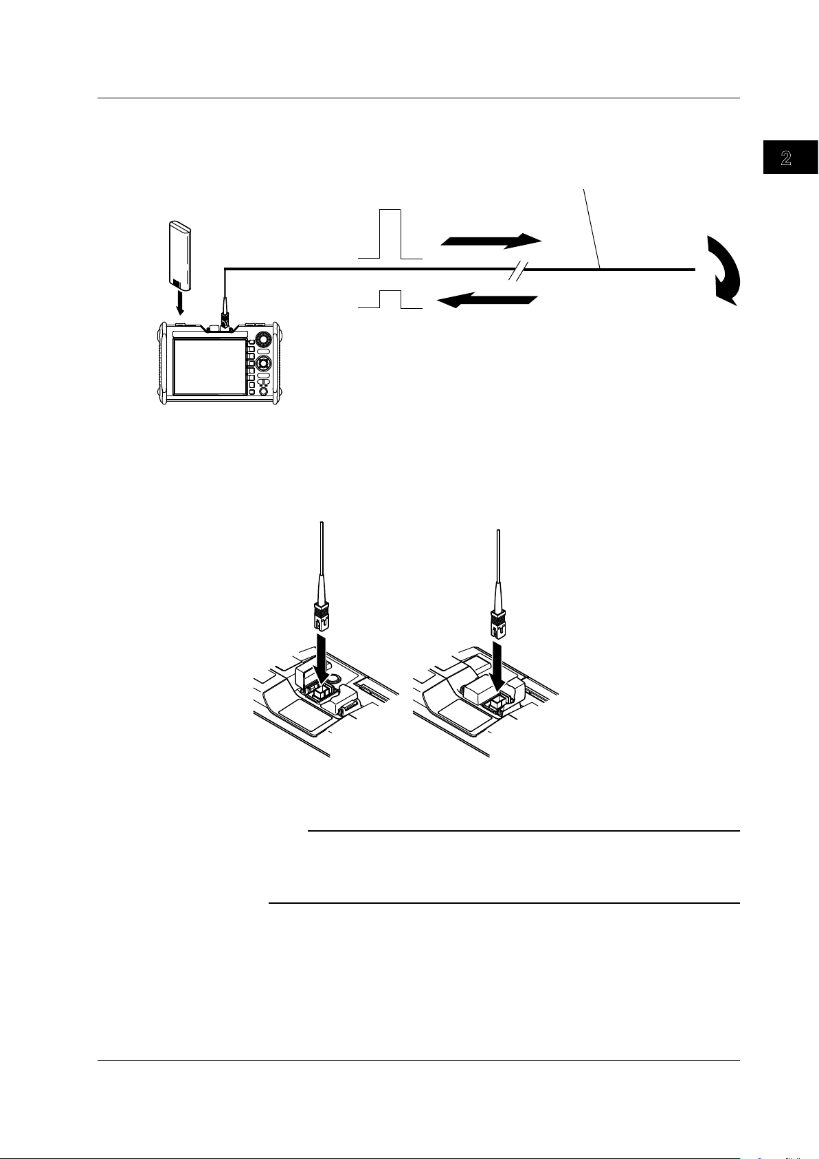
1
Optical Pulse Measurement (OTDR) Configuration
Reflection point
Battery pack
Optical fiber cable
under measurement
Optical pulse
output
Return ray due
to reflection
* Do not bend the optical fiber cable.
[PORT1][PORT2]
Install the battery pack and connect the optical fiber cable under measurement.
There are two optical connectors on the top panel of the AQ7270/AQ7275.Because the
connector that delivers the optical pulse is fixed depending on the wavelength, connect
the cable to the appropriate connector according to the condition of the optical fiber
cable to be measured. You can view the indicator shown on the display (see page 1-5) to
choose the appropriate connector.
2.1 Measurement Configuration
Measurement Overview
This also applies when using the optional optical power monitor or light source function.
Note
• The 735021 outputs 1650 nm from PORT1.
• The 735029 outputs 850 nm and 1300 nm from PORT1.
• The /PM option supports only PORT1. PORT2 (MMF) and 1650-nm wavelength are not
supported.
When Using the Angled PC SC Connector (Suffix Code:-ASC)
• Use the same type of angled PC SC connector for the connected optical fiber cable
as well.
The ferrule end of the angled PC SC connector is polished to
If other types of connectors are used, the end face of the connector may become
damaged.
• You can replace the
an angle.
AQ7270/AQ7275 connector, but only with an SC type.
IM 735020-01E
2-3
Page 31

2.2 Measurement Procedure
Measurement Preparation
Measurement Condition Setup
(Select from the Following Three)
Waveform Display Conditions
Connect the power supply and turn it ON/OFF
Connect the optical fiber cables
Set the date and time
Load the printer paper
When setting only the wavelength
and using auto setup for other
items (full auto mode)
When setting measurement
conditions using the wizard
(measurement wizard mode)
When specifying all items
(detail mode)
• Expand or reduce
• Move the waveform
• Display the grid and information
Waveform Analysis
• Measure the distance
• Measure the splice loss and return loss
• Editing the waveform
• Analyze multiple waveforms
Waveform Printing and Storage
• Print the display image
• Save various types of data
Section 3.1
Section 3.2
Section 3.3
Section 3.4
Chapter 4
Chapter 5
Chapter 6
Section 8.1
Section 8.2
Section 19.2
Section 18.5
Sections 18.1 to 18.4
One-Button
Measurement
Select a macro
and execute
Section 9.3
Waveform Acquisition
• Realtime measurement
• Averaging measurement
Section 7.1
Section 7.2
Multicore Fiber
Measurement
Create a project
and execute
Section 7.5
Chapter 10
Chapter 11
Section 12.2
Chapter 13
Flow of Operation
The figure below is provided to familiarize the first-time user with the general flow of the
AQ7270/AQ7275 operation. For details on each item, see the relevant section or chapter.
2-4
IM 735020-01E
Page 32

2
1
2.2 Measurement Procedure
One-Button Measurement <<For procedures, see section 9.3.>>
If you enter the settings such as the optical pulse measurement conditions, waveform
acquisition mode, and data format for storage in advance, you can carry out the
measurement and storage through a single-step operation. If you enter multiple sets
of settings such as the wavelengths to be measured, you can carry out measurements
sequentially using different measurement conditions through one-step operation.
Easy Setting of Measurement Conditions
There are three modes for setting the measurement conditions: Detail, Measurement
Wizard, and Full Auto.
In Detail mode, the user sets each measurement condition as in the past.
In Measurement Wizard mode, a wizard is displayed when the user sets each
measurement condition. This feature is convenient for users that are not used to the
work.
In Full Auto mode, all optical pulse measurement conditions are automatically set when
you select the wavelength to be measured, and the measured waveform is displayed.
This feature is convenient when you are not sure about the installation conditions of the
optical fiber cable.
Waveform Acquisition and Measurement Using Markers and Cursors
The AQ7270/AQ7275 has the following two measurement functions.
• Acquire the waveform
• Position markers or cursors on the acquired waveform and measure the values.
Measurement Overview
Multi Wavelength Measurement <<For procedures, see section 6.3 and 6.4.>>
The multi wavelength measurement is performed on the following wavelengths: 850nm,
1300nm, 1310 nm, 1490 nm, 1550 nm, and 1625 nm.
Measurement at multiple wavelengths can be carried out continuously.
The number of wavelengths that can be measured and waveforms that can be displayed
differs depending on the model (up to 3 waveforms).
Measuring Multicore Fiber <<For procedures, see section 7.5.>>
Specialized screens (Main View Screen) and menus for multicore fiber measurements
appear, enabling you to efficiently measure multicore fibers without data loss.
IM 735020-01E
2-5
Page 33

Measurement Preparation
Configure the core information
Configure settings such as the number of cores
and how to assign numbers.
Set the measurement conditions
Set conditions such as the wavelength and
the distance range.
Set the analysis conditions
Set conditions such as the group refraction
index and the reference waveform (before work).
Section 17.2
Section 17.3
Section 17.4
Measurements before Work
Measure the optical pulse
Measure cores numbered 1 to 100 (maximum)
in order.
Section 17.1
Measurements after Work
Measure the optical pulse (core number 1)
Measure core number 1.
Check the measured waveform
Perform a visual check of the core number 1
waveform and the waveform before work
(the reference).
Analyze the measured waveform
(if necessary)
Use markers or line markers to perform
calculations on the core number 1 waveform,
and check the events as numeric values.
Measure the optical pulse
(core number 2 and greater)
Repeat the checks listed above for cores
numbered 2 to 100 (maximum).
Section 17.1
Section 17.1
Section 17.1
2.2 Measurement Procedure
Multi Core Trace Comparison (Firmware Versions 3.01 and Later)
<<For procedures, see chapter 17.>>
When installed fibers are moved because of road work or other external factors, you can
efficiently perform measurements by using this function.
The following three measurement methods are available, each of which checks the
quality of the optical pulse measurement waveform after work.
•
Visual check of the waveform before work and the waveform a
• Visual check using a waveform of one fiber within the same tape as the reference
• Automatic pass/fail judgment using pass/fail markers
Visual Check of the Waveform before Work and the Waveform after Work
fter work
2-6
IM 735020-01E
Page 34

2
1
Measurement Preparation
Configure the core information
Configure settings such as the number of
cores and how to assign numbers.
Set the measurement conditions
Set conditions such as the wavelength and
the distance range.
Set the analysis conditions
Set conditions such as the group refraction
index and the reference waveform (tapes a to j).
Section 17.2
Section 17.3
Section 17.4
Measurements before Work
Measure the optical pulse
Measure 12 tapes worth of waveforms—
the cores numbered 1a to 12a (maximum) of
the tape ID—in order (in this example, tape a is
the reference waveform).
Section 17.1
Measurements after Work
Measure the optical pulse (1a of tape 1)
Measure the core numbered 1a of tape 1.
Check the measured waveform
Perform a visual check of the core number 1a
waveform of tape 1 and the waveform
before work (the reference).
Analyze the measured waveform
(if necessary)
Use markers or line markers to perform
calculations on the core number 1a waveform
of tape 1, and check the events as numeric
values.
Measure the optical pulse
(1b and greater of tape 1)
Perform a visual check of the core number 1b
waveform and the core number 1a waveform
of tape 1 (the reference is tape a).
Perform the same visual check using the 1c
and greater waveforms and the 1a waveform.
Measure the optical pulse
(tape 2 and greater)
Repeat the checks listed above.
Section 17.1
Section 17.1
Section 17.1
Section 17.1
2.2 Measurement Procedure
Visual Check Using a Waveform of One Fiber within the Same Tape as the
Reference
Measurement Overview
IM 735020-01E
2-7
Page 35

Measurement Preparation
Configure the core information
Configure settings such as the number of
cores and how to assign numbers.
Set the measurement conditions
Set conditions such as the wavelength
and the distance range.
Configure the pass/fail markers
Position markers above the events
(2 markers, 4 markers, or 5 markers method),
set the threshold levels, and configure other
settings.
Section 17.2
Section 17.3
Section 17.4
Measurements after Work
Measure the optical pulse
Measure cores numbered 1 to 100 (maximum)
in order.
Each time that the measurement of a core is
completed, the AQ7270/AQ7275 automatically
performs a pass/fail measurement and displays
the results on the screen.
Section 17.1
2.2 Measurement Procedure
Automatic pass/fail judgment using pass/fail markers
2-8
IM 735020-01E
Page 36

2
1
2.3 Viewing the Optical Pulse Measurement
Incident ray
Backscattering
light
Fused
connection
point
Connector
connection
point
Bending
Open end
Near-end reflection
Splice loss due to fusion
Approximation line
Reflection due to
Connector Connection
Loss due to bending
Open end reflection
(Fresnel reflection)
Dynamic range(SNR=1)
Small
material
Incident ray
Backscattering
light
Optical fiber cable
Waveform
Measurement Overview
An optical pulse that enters the optical fiber cable incurs loss due to reflection at the
connection points, etc. The measured result is displayed with the distance along the
horizontal axis and loss level along the vertical axis. Waveform refers to the display of
this result on the AQ7270/AQ7275. The losses and reflections detected on the waveform
are called events.
Near-End Reflection
A reflection occurs in the connection point between the AQ7270/AQ7275 and the
connector for the optical fiber cable. This section also includes the internal reflection of
the OTDR. Losses and reflections of the connection points cannot be detected in the
section in which this reflection is detected. This section is called a near-end dead zone.
If the near-end reflection affects the measurement of a short distance, connect a dummy
fiber provided as an option to clear the effects.
Loss by the Optical Fiber Cable due to Rayleigh Scattering
When light propagates through the optical fiber cable, a phenomenon called Rayleigh
Scattering occurs due to the nonuniformity of the density or constituents of materials
smaller than the wavelength unit. The scattered light that is transmitted opposite to the
direction of propagation is called backscattering light.
IM 735020-01E
2-9
Page 37

Optical fiber cable
Optical fiber cable
Gap
Connector
Glass Air
Incident ray (100%)
Reflected ray (3%)
Light
(97%)
Measurement
waveform
Noise peak
2.6 dB
RMS level of noise
Dynamic range
(SNR=1)
2.3 Viewing the Optical Pulse Measurement Waveform
Splice Loss due to Fusion
Because the unevenness in the density or constituents of the materials in the fused
section becomes large, the loss due to Rayleigh Scattering increases, and a splice loss
occurs.
Reflection due to Connector Connection
Unlike the fused section, a slight gap occurs in the connection section of connectors.
Because the group refraction index changes in this gap, a reflection occurs causing a
loss.
Fresnel Reflection at the Far End of the Optical Fiber Cable
Fresnel reflection occurs at the location where the optical fiber cable is broken or a
location where the group refraction index changes such as the far end of the cable (glass
and air) when light enters the cable. If the end face of the optical fiber cable is vertical,
approximately
%(–14.7dB)oftheincidentlightpowerisreflected.
3
Dynamic Range
2-10
The backscattering light level that the AQ7270/AQ7275 can measure.
IM 735020-01E
Page 38

2
1
2.4 Distance Measurement
Accuracy
The AQ7270/AQ7275 calculates the distance (L) by measuring the time until the
transmitted light pulse returns and using the equation indicated below.
L = C×T/(2N) [m]
C:
The speed of light travelling through a vacuum.
The time from when the pulse is transmitted until the light returns.
T:
N: Group refraction index
The reason why the equation divides by 2 is because the round-trip time of the optical
pulse is measured.
An error will occur in the distance measurement unless an accurate group refraction
index is specified.
Group Refraction Index Settings
The following group refraction indexes are assigned according to the wavelength on the
AQ7270/AQ7275.
850 nm: 1.46000
1300 nm: 1.46000
1310 nm:
1490 nm: 1.46000
1550 nm:
1625 nm: 1.46000
1650 nm: 1.46000
The selectable range is 1.30000 to 1.79999.
For the accurate group refraction index, check with the manufacturer of the optical fiber
cable.
1.46000
1.46000
Measurement Overview
Optical Fiber Cable Length and Distance Range
Select a distance range that is longer than the optical fiber cable you want to measure. If
the distance range is longer, the measurement time also increases accordingly.
Cable Length Distance Range
Unknown Auto
0 to 400 m 500 m
400 m to 800 m 1 km
800 m to 1.6 km 2 km
1.6 km to 4 km 5 km
4 km to 8 km 10 km
8 km to 16 km 20 km
16 km to 40 km 50 km
40 km to 80 km 100 km
80 km to 160 km 200 km
160 km to 240 km 300 km
IM 735020-01E
2-11
Page 39

Pulse width
Event dead zone
Attenuation dead zone
1.5 dB
2.4 Distance Measurement
Selectable Pulse Widths for the Distance Measurement
The pulse width has the following characteristics.
Short pulse width: Allows events (reflection point and loss) that are close together
to be measured separately. However, long distance cannot be
measured.
Long pulse width: Long distance can be measured. However, multiple events that
are close together may appear as a single event.
Distance Range Selectable Pulse Widths
500 m 3 ns, 10 ns, 20 ns, 50 ns, 100 ns, 200 ns, 500 ns
1 km 3 ns, 10 ns, 20 ns, 50 ns, 100 ns, 200 ns, 500 ns, 1 ms
2 km 3 ns, 10 ns, 20 ns, 50 ns, 100 ns, 200 ns, 500 ns, 1 ms
5 km 3 ns, 10 ns, 20 ns, 50 ns, 100 ns, 200 ns, 500 ns, 1 ms
10 km, 20 km 3 ns, 10 ns, 20 ns, 50 ns, 100 ns, 200 ns, 500 ns, 1 ms
50 km or longer 3 ns, 10 ns, 20 ns, 50 ns, 100 ns, 200 ns, 500 ns, 1 ms, 2 ms, 5 ms,
10 ms, 20 ms
If the wavelength is 850 nm, you cannot use 3ns, 2 ms, 5 ms, 10 ms, and 20 ms(3 ns is available
on the 735041).
If the wavelength is 1300 nm, you cannot use 3ns, 10 ms and 20 ms (3 ns is available on the
735041)
.
Dead Zone in Which the Distance Cannot Be Measured
The locations where measurements cannot be made due to the effects of connection
point of connectors, etc. The following types of dead zones are available.
• Event dead zone
Area in which two reflections that are close together cannot be separated.
defined by a pulse width whose level is 1.5 dB less than the peak value.
• Attenuation dead zone
A zone in which the splice loss cannot be measured due to a l
A zone
arge reflection nearby.
2-12
IM 735020-01E
Page 40

2
1
Optical fiber cable
under measurement
Dummy fiber
Location of event
occurrence
* Do not bend the optical fiber cable.
Small reflection hidden behind a large reflection
2.4 Distance Measurement
Circumventing the Near-End Dead Zone Using a Dummy Fiber
Losses and reflections of the connection points cannot be detected in the section in
which a near-end reflection is detected. When measuring a short distance, connect the
dummy fiber to move the events that are hidden behind the near-end reflection by the
length of the dummy fiber.
Measurement Overview
Note
The AQ7270/AQ7275 OTDR product series allow a 100-m dummy fiber to be built in (/DF
option).
IM 735020-01E
2-13
Page 41

3
2
1
Chapter 3 Measurement Preparation
3.1 Connecting the Power Supply
Using the AC Adapter
WARNING
Make sure that you observe the following points before connecting the AC adapter.
Failure to do so may cause electric shock or damage to the instrument.
• Check that the AQ7270/AQ7275 is turned OFF before connec
adapter.
• Use only the power cord supplied by YOKOGA
• Before connecting the power cord, ensure that the source voltage matches the
rated supply voltage of the AC adapter and that it is within the maximum rated
voltage of the provided power cord.
•
Use only the AC adapter specified for the instrument.
When unplugging the power cord from the outlet, never pull the cord itself.
•
Always hold and pull by the plug. If the power cord is damaged, contact your
dealer for replacement.
•
Do not plug or unplug the AC adapter while the instrument is t
• If you are using the instrument for an extended time with the AC adapter
connected, remove the battery pack from the instrument.
• If you are not going to use the instrument for an extended time, unplug the
power cord of the
• Be sure nothing is placed on top of the AC adapter or power c
generating objects come in contact with them.
• If an AC outlet that matches the power cord provided is unava
the instrument.
AC adapter from the outlet.
WA for the instrument.
ting the AC
urned ON.
ord or let heat
ilable, do not use
Measurement Preparation
IM 735020-01E
3-1
Page 42

POWER lamp
CHARGE lamp
Green: Running
Red: Low battery level
Green: Fast charging in progress
Green(blinking): Fast charging not started
• The battery pack is not loaded correctly in the AQ7270/AQ7275.
• Battery pack temperature not within the allowable range
for fast charging.
• The battery pack is in the preliminary charging condition
because the battery charge is too low for fast charging.
Check that the battery pack is loaded correctly. If the green lamp does not
illuminate even after 2 or 3 hours passes with the AC adapter connected,
the battery pack may be broken or reduced life.
3.1 Connecting the Power Supply
Connect the power cord to the AC adapter.
1.
Connect the AC adapter plug to the instrument.
2.
Connect the power plug to the outlet.
3.
Note
If the DC power connector cover comes off, bend the axis section of the cover and attach it.
Turning the Power ON
4.
Press the power switch on the front panel of the instrument. The POWER lamp
illuminates.
3-2
IM 735020-01E
Page 43

3
2
1
Using the Battery Pack
Put the battery pack string way in
the dented section in the back.
Push up
Pull out
WARNING
• Do not remove or insert the battery pack while being charged with the AC
• To prevent problems with the
•
Charge the battery pack using the instrument. Be sure to observe the
1.
2.
3.
4.
5.
3.1 Connecting the Power Supply
adapter.
battery pack, periodically check the physical
appearance for cracks, deformation, and leaks.
environmental conditions when charging the battery pack. Otherwise, leaks,
overheating, smoke, explosion, or fire may occur
Push up the battery pack cover lock.
Pull out the battery pack cover while pushing the lock up.
Insert the battery pack. Pay attention to the direction.
Put the battery pack string way in the dented section in the back.
Close the battery pack cover and securely lock the battery pack cover.
.
Measurement Preparation
Note
• Charge the battery pack in advance when using it for the first time or after long periods of
non-use. The remaining battery charge may be low due to self-discharging.
• If you attempt to charge a battery pack that is overly discharged, the battery pack enters the
preliminary charging condition* and it may take about 2 hours for the fast charging to start.
• The AQ7270/AQ7275 draws minute current even if the power switch is turned OFF. If you
do not plan to use the AQ7270/AQ7275 for longer than a week, we recommend that you
remove the battery pack from the AQ7270/AQ7275. If you do not use the AQ7270/AQ7275
for a long time with the battery pack loaded, the battery pack may become overdischarged.
* For a description of the preliminary charging condition, see “Charging Conditions of the
Battery Pack.”
IM 735020-01E
3-3
Page 44

3.1 Connecting the Power Supply
Explanation
Charging Conditions of the Battery Pack
There are four charging operations
• Preliminary Charging
This function is designed to reactivate a battery pack that is overly discharged or
deactivated due to temperatures lower than the specifications’ allowable range
(when engaged, the CHARGE lamp blinks green). If the battery pack is overly
discharged, the preliminary charge can take two hours or more. When preliminary
charging is complete, fast charging begins automatically
•
Fast Charging
Normally (under standard operating conditions with a problem-free battery pack),
fast charging begins simultaneously when powering with the
chargingcharges
charging takes approximately two hours, depending on the original battery level
and environmental conditions.
• Top-of
This function engages immediately after fast charging, and runs on a three-
hour
provided by the fast charging function). When fast charging finishes, the CHARGE
lamp goes out and the battery pack will be charged continuously for three hours.
Charging of the battery pack is complete after five hours: two hours of fast charging
and three hours of top-off charging.
•
Maintenance Charging
This function compensates for the battery pack’s self-discharging. If the
battery pack continues to be powered by the
maintenance charging will be employed to compensate for self-discharging (when
engaged, the CHARGE lamp is turned OFF).
.
AC adapter
thebatterypacktoupto80–90%ofitsfullcapacity.Fast
f Charging
timertobringthechargeupto100%(theremainingamountofchargenot
AC adapter after top-off charging,
. Fast
Note
The CHARGE lamp also blinks green if the battery pack is not installed or if the temperature is
outside the allowable range for fast charging.
Warm-up
Allow the instrument to warm up for at least 30 minutes after turning ON the power.
Sufficient warm-up produces more accurate measurements.
Overdischarging
If you do not use the AQ7270/AQ7275 for a long time with the battery pack loaded, the
battery pack may become overdischarged.
Please note that this can lead to reduced life of the battery pack.
If not using the AQ7270/AQ7275 for one week or more, prevent overdischarging by
charging the battery pack, removing it from the AQ7270/AQ7275, then storing it away
from
sunlight
more, compensate for self-discharging by charging it with the instrument once a month.
ina10–30°Cenvironment.Whenstoringthebatterypackforonemonthor
3-4
IM 735020-01E
Page 45

3
2
1
3.2 Connecting the Optical Fiber Cable
Good example
Cleaning the Connector End Face of the Optical Fiber Cable
Clean the connector end face of the optical fiber cable under measurement before
connecting it to the AQ7270/AQ7275. If dust is adhered to the connector end face, it
may damage the optical connector of the AQ7270/AQ7275. If this happens, the AQ7270/
AQ7275 will not be able to make correct measurements.
Press the connector end face of the optical fiber cable firmly against the cleaning
1.
surface of the cleaner.
Turn the cable around once with the end face pressed against the cleaner.
2.
Rub the end face against the cleaner.
3.
Repeat steps 1 to 3.
4.
Measurement Preparation
Note
• If you do not press the connector end face of the optical fiber cable firmly against the
cleaner, the end face may not be cleaned completely.
• You can purchase an optical fiber connector cleaner from NTT-AT corporation.
Connecting the Optical Fiber Cable to the AQ7270/AQ7275
Open the optical connector cover at the top of the AQ7270/AQ7275.
1.
Match the direction of the optical fiber cable connector to the optical connector,
2.
and insert it.
IM 735020-01E
3-5
Page 46

Optical pulse output indicator
Bad example
3.2 Connecting the Optical Fiber Cable
Note
The connector to which the cable is to be connected varies depending on the wavelength.
•
Connect the cable to the connector that is indicated by the red indicator at the top of the
AQ7270/AQ7275 display.
•
Power monitor measurement uses only POR
CAUTION
When connecting the optical fiber cable connector, insert it vertically and slowly
into the optical connector. If you tilt the connector or insert the connector by force,
the optical connector may break.
T1.
There are many optical connectors that have inferior parts which do not meet
standards.
Only use optical connectors that are approved or used by your country or region’s
communications industry or other authoritative body (e.g. products from NTT
technology transfer or their equivalents).
When Using the Angled PC SC Connector (Suffix Code:-ASC)
•
Use the same type of angled PC SC connector for the connected optical fiber
cable as well.
The ferrule end of the angled PC SC connector is polished to an angle.
If other types of connectors are used, the end face of the connector may
become damaged.
• You can replace the
AQ7270/AQ7275 connector, but only with an SC type.
Note
If the suffix code is -NON, -USC, or -UFC, attach the optical universal adapter. For details, see
section 20.8.
3-6
IM 735020-01E
Page 47

3
2
1
3.3 Setting the Date and Time
Select the display format
of the date and time
Selecting the Detail Mode
Press the OTDR soft key. The optical pulse measurement display appears.
1.
Press SETUP. Soft keys for the settings appear.
2.
Press the Mode soft key. A soft key menu for selecting the setup mode appears.
3.
Press the Detail soft key. Soft keys for the Detail mode appear.
4.
Press the System Setup soft key. The system setup screen appears.
5.
Measurement Preparation
Note
• The setup menu does not appear even if you press SETUP if you press a soft key other
than OTDR.
• You can also set the AQ7270/AQ7275 using Simple (Full Auto) mode.
IM 735020-01E
3-7
Page 48

Select the display format
of the date and time
3.3 Setting the Date and Time
Selecting the Date and Time
Move the cursor using the arrow keys or the rotary knob to highlight Date&Time
6.
Set.
Press ENTER. The screen for setting the date and time appears.
7.
Move the cursor to the item you want to set using the arrow keys or the rotary
8.
knob.
Press ENTER. The screen for setting the value appears.
9.
Turn the rotary knob to set the date or time value.
10.
Press ENTER. The screen for setting the value closes.
11.
Move the cursor using the arrow keys or the rotary knob to SET.
12.
Press ENTER. The date and time are set to the AQ7270/AQ7275.
13.
Date and Time Display Format
14.
15.
16.
17.
18.
19.
20.
Note
The date and time values displayed in Type are examples. They do not indicate the actual date
and time.
Move the cursor using the arrow keys or the rotary knob to highlight Type.
Press ENTER. The screen for setting the type appears.
Move the cursor using the arrow keys or the rotary knob to select the type.
Press ENTER. The screen for setting the type closes.
Press ESC. The screen for setting the date closes.
Press ESC. The system setup screen closes.
Press ESC. The setup screen of the Detail mode closes, and the optical pulse
measurement screen appears.
3-8
IM 735020-01E
Page 49

3
2
1
3.4 Loading the Printer Roll Paper (Option)
Printer cover
Lock lever
Printer paper feed button
Push the lock toward the arrow and
slide the cover
Pick up the cover and remove it
Load the paper inside the paper guide
Close the cover so that the paper does not get
caught in the tabs and push the cover in
Tabs
Measurement Preparation
Push the lock lever toward the arrow and remove the printer cover.
1.
Load the printer roll paper. See the figure below for the orientation of the roll
2.
paper.
Attach the printer cover.
3.
IM 735020-01E
Press the printer paper feed button to feed the paper to the appropriate position.
4.
3-9
Page 50

3.5 Connecting the USB Interface
Connecting a USB Printer, USB Memory or USB104 keyboard
Open the top cover.
1.
Connect a USB cable to the Type A connector.
2.
Note
• A single USB printer can be connected. Multiple printers will not be detected.
• You can operate the panel keys by using the USB104 keyboard. See appendix 2 for the
correspondence between panel keys and USB keyboard entry keys.
Connecting a USB Cable to Remotely Control the AQ7270/AQ7275 or
Accessing the Internal Memory
1.
2.
Note
• If the cover comes off, bend the cover axis with your fingers and attach it.
• The system must be configured for operation. See section 19-1.
Open the top cover.
Connect a USB cable to the Type B connector.
3-10
IM 735020-01E
Page 51

3
2
1
3.6 Connecting the Ethernet Interface (Option)
You can control the AQ7270/AQ7275 via the Ethernet interface.
Connection Procedure
Connect a UTP (Unshielded Twisted-Pair) cable or an STP (Shielded Twisted-Pair) cable
that is connected to a hub, for example, to the AQ7270/AQ7275 connector.
Note
• Be sure to use a straight cable via a hub to connect the AQ7270/AQ7275 to the PC.
• If you are using a UTP cable (straight), use a cable of category 5.
• If the cover comes off, bend the cover axis with your fingers and attach it.
• The system must be configured for operation. See section 19-3.
Measurement Preparation
IM 735020-01E
3-11
Page 52

3.7 Attaching the Belt
1
2
3
4
Pass the belt through the buckle again, so it does not come loose.
A hand belt is supplied as a standard accessory. On models with the /SB option, a
shoulder belt is also included. This section explains how to attach the belt.
CAUTION
Pass the belt through the buckle and fasten it firmly according to the procedure in
this section. If the belt is loose or the belt is passed through only one of the holes in
the buckle, the belt may slip off and the instrument may fall.
How to Attach the Hand Belt
The hand belt can be attached to the left or right side of the instrument. Attach the belt to
the desired side. There are two hand belt attachment sections. Securely attach the hand
belt at the two sections.
Pass the hand belt through the lower hand belt attachment section on the side of
1.
the instrument.
Pass the hand belt through the hand belt cover.
2.
Pass the hand belt through the upper hand belt attachment section (the second
3.
attachment section from the top) on the side of the instrument.
Pass the hand belt through the buckle.
4.
Fasten the buttons of the hand belt cover.
5.
How to Attach the Shoulder Belt
The shoulder belt can be attached to the shoulder belt attachment section on the left and
right sides of the AQ7270/AQ7275. As shown in the figure below, securely attach the
shoulder belt by passing the belt through the top belt attachment section on each side of
the instrument and then pass it through the buckle.
3-12
IM 735020-01E
Page 53

4
3
2
1
Chapter 4 Setting the Optical Pulse Measurement Conditions (Simple Full Auto Mode)
4.1 Selecting the Test Wavelength
Procedure
Select the Simple Setup Mode
Press the OTDR soft key. The optical pulse measurement display appears.
1.
Press SETUP. A soft key menu for the settings appears.
2.
Press the Mode soft key. A soft key menu for selecting the setup mode appears.
3.
Press the Simple (Full auto) soft key. The Simple (Full Auto) setup screen
4.
appears.
Selecting the Test Wavelength
Press ENTER. A screen for selecting the wavelength appears.
5.
Move the cursor to the wavelength you want to select using the arrow keys or the
6.
rotary knob.
Press ENTER. A screen for selecting the wavelength closes.
7.
Press ESC. The Simple (Full Auto) Setup screen closes, and the optical pulse
8.
measurement screen appears.
Setting the Optical Pulse Measurement Conditions (Simple Full Auto Mode (Set Only the Wavelength))
Note
• The selectable test wavelengths vary depending on the model. For details, see section 21.1.
• The optical pulse output port changes depending on the wavelength.
• The setting is stored in the internal memory. The AQ7270/AQ7275 will start up using the
stored settings when the power is turned ON the next time.
IM 735020-01E
4-1
Page 54

4-2
IM 735020-01E
4.1 Selecting the Test Wavelength
Explanation
The following measurement conditions are automatically detected.
• Distance range
• Pulse width
• Event detection
• Measurement result file storage
The list below contains the measurement conditions for the Simple (Full Auto) mode.
You can view the following information in the measurement setup information. For details,
see section 7.3.
Item Setting
Distance range Auto
Pulse width Auto
Attenuation Auto
Averaging duration Auto
Averaging method High reflection
Averaging unit Duration
Sampling interval Normal
Page 55

4
3
2
1
4.2 Selecting the Approximation Method
Procedure
Parameters such as the splice loss and return loss are calculated using linear
approximation. There are two linear approximation methods: least square and two point.
Select the Simple Setup Mode
1.
2.
3.
4.
Selecting the Approximation Method
5.
Press the OTDR soft key. The optical pulse measurement display appears.
Setting the Optical Pulse Measurement Conditions (Simple Full Auto Mode (Set Only the Wavelength))
Press SETUP. A soft key menu for the settings appears.
Press the Mode soft key. A soft key menu for selecting the setup mode appears.
Press the Simple (Full auto) soft key. The Simple (Full Auto) setup screen
appears.
Press the ApproxMethod (Marker) soft key. The cursor moves, and the
approximation method switches.
Note
• Approximation method (event) is fixed to LSA(least square).
• There are two approximation methods: LSA and TPA (two point). For a detailed explanation,
see section 6.2.
IM 735020-01E
4-3
Page 56

4-4
IM 735020-01E
4.3 Setting Other Items
Procedure
This section describes system settings such as the save destination of the measured
result, language setting, and date/time setting in addition to the measurement condition
settings.
Select the Simple Setup Mode
Press the OTDR soft key. The optical pulse measurement display appears.
1.
Press SETUP. A soft key menu for the settings appears.
2.
Press the Mode soft key. A soft key menu for selecting the setup mode appears.
3.
Press the Simple (Full auto) soft key. The Simple (Full Auto) setup screen
4.
appears.
Selecting the Auto Save Destination
Press the Auto Save Drive soft key.
5.
A screen for selecting the save destination appears.
6.
Move the cursor to the save destination you want to select using the arrow keys
7.
or the rotary knob.
Press ENTER. A screen for selecting the save destination closes.
8.
Press ESC. The Simple (Full Auto) Setup screen closes, and the optical pulse
9.
measurement screen appears.
Page 57

4
3
2
1
4.3 Setting Other Items
Selecting the Language and Setting the Date and Time
• Selecting the Language
Press the System Setup soft key. The system setup screen appears.
5.
Move the cursor using the arrow keys or the rotary knob to highlight Language.
6.
Press ENTER. A screen for selecting the language appears.
7.
Move the cursor to the language you want to select using the arrow keys or the
8.
rotary knob.
Press ENTER. The language is confirmed.
9.
Press ESC. The system setup screen closes.
10.
Press ESC. The Simple (Full Auto) Setup screen closes, and the optical pulse
11.
measurement screen appears.
• Selecting the Date and Time
Press the System Setup soft key. The system setup screen appears.
5.
Move the cursor using the arrow keys or the rotary knob to highlight Date &
6.
Time Set.
Press ENTER. The screen for setting the date and time appears.
7.
Move the cursor to the item you want to set using the arrow keys or the rotary
8.
knob.
Press ENTER. A screen for selecting the value appears.
9.
Turn the rotary knob to set the date or time value.
10.
Press ENTER. The screen for setting the value closes.
11.
Move the cursor using the arrow keys or the rotary knob to highlight SET.
12.
Press ENTER. The date and time are set to the AQ7270/AQ7275.
13.
Setting the Optical Pulse Measurement Conditions (Simple Full Auto Mode (Set Only the Wavelength))
• Date and Time Display Format
Move the cursor using the arrow keys or the rotary knob to highlight Type.
14.
Press ENTER. The screen for setting the type appears.
15.
Move the cursor using the arrow keys or the rotary knob to select the type.
16.
Press ENTER. The type is confirmed.
17.
Press ESC. The screen for setting the date closes.
18.
Press ESC. The system setup screen closes.
19.
Press ESC. The Simple (Full Auto) Setup screen closes, and the optical pulse
20.
measurement screen appears.
IM 735020-01E
4-5
Page 58

4.3 Setting Other Items
Explanation
Auto Save
The AQ7270/AQ7275 creates folders indicating the date and time in the selected drive
and automatically saves the measurement result files.
File type SOR
File name format File name format specified in the File menu.
4-6
IM 735020-01E
Page 59

5
4
3
2
1
Select the wavelength (see page 5-2 for the procedure)
Select the distance range (see page 5-2 for the procedure)
Select the pulse width (see page 5-3 for the procedure)
Select the averaging method of the waveform
(see page 5-3 for the procedure)
Select the sampling interval (see page 5-4 for the procedure)
Select the attenuation value (see page 5-4 for the procedure)
Select the averaging unit (see page 5-5 for the procedure)
Select the averaging duration or count
(see page 5-6 for the procedure)
Enable/disable the plug check
(see page 5-7 for the procedure)
Enable/disable the Fiber-In-Use alarm
(see page 5-7 for the procedure)
Chapter 5 Setting the Optical Pulse Measurement Conditions (Measurement Wizard Mode)
5.1 Setting the Measurement Conditions
Procedure
Selecting the Measurement Wizard Mode
Press the OTDR soft key. The optical pulse measurement display appears.
1.
Press SETUP. A soft key menu for the settings appears.
2.
Press the Mode soft key. A soft key menu for selecting the setup mode appears.
3.
Press the Measurement Wizard soft key. A soft key menu for the measurement
4.
setup (wizard) appears.
Setting the Measurement Conditions
Press the Meas Setup soft key. The Measurement (Wizard) screen appears.
5.
Setting the Optical Pulse Measurement Conditions (Measurement Wizard Mode (Displays Setup Explanations))
IM 735020-01E
5-1
Page 60

5-2
IM 735020-01E
5.1 Setting the Measurement Conditions
• Selecting the Wavelength
Move the cursor to Wavelength using the arrow keys or the rotary knob.
6.
Press ENTER. A wizard screen for selecting the wavelength appears.
7.
Press ENTER. A screen for selecting the wavelength appears.
8.
Move the cursor to the wavelength you want to select using the arrow keys or the
9.
rotary knob.
Press ENTER. The wavelength is confirmed.
10.
Note
• The selectable test wavelengths vary depending on the model. For details, see section 21.1.
• The optical pulse output port changes depending on the wavelength.
• The setting is stored in the internal memory. The AQ7270/AQ7275 will start up using the
stored settings when the power is turned ON the next time.
• Select the Distance Range
11.
12.
13.
14.
15.
Note
For a detailed explanation, see section 6.1.
Move the cursor to Distance Range using the arrow keys or the rotary knob.
Press ENTER. A wizard screen for selecting the distance range appears.
Press ENTER. A screen for selecting the distance range appears.
Move the cursor to the distance range you want to select using the arrow keys or
the rotary knob.
Press ENTER. The distance range is confirmed.
Page 61

5
4
3
2
1
• Selecting the Pulse Width
16.
17.
18.
19.
20.
Note
5.1 Setting the Measurement Conditions
Move the cursor to Pulse Width using the arrow keys or the rotary knob.
Press ENTER. A wizard screen for selecting the pulse width appears.
Press ENTER. A screen for selecting the pulse width appears.
Move the cursor to the pulse width you want to select using the arrow keys or the
rotary knob.
Press ENTER. The pulse width is confirmed.
Setting the Optical Pulse Measurement Conditions (Measurement Wizard Mode (Displays Setup Explanations))
• You cannot select the pulse width if the distance range is set to auto.
• For a detailed explanation, see section 6.1.
• Selecting the Averaging Method
21.
22.
23.
24.
25.
Note
Move the cursor to Avg Method using the arrow keys or the rotary knob.
Press ENTER. A wizard screen for selecting the averaging method appears.
Press ENTER. A screen for selecting the averaging method appears.
Move the cursor to the averaging method you want to select using the arrow
keys or the rotary knob.
Press ENTER. The averaging method is confirmed.
For a detailed explanation, see section 6.1.
IM 735020-01E
5-3
Page 62

5-4
IM 735020-01E
5.1 Setting the Measurement Conditions
• Setting the Attenuation
Move the cursor to Attenuation using the arrow keys or the rotary knob.
26.
Press ENTER. A wizard screen for setting the attenuation appears.
27.
Press ENTER. The screen for setting the attenuation appears.
28.
Move the cursor to the attenuation value you want to select using the arrow keys
29.
or the rotary knob.
Press ENTER. The attenuation is confirmed.
30.
Note
• For a detailed explanation, see section 6.1.
• You cannot select the attenuation if the averaging method is set to high reflection.
• Selecting the Sampling Interval
31.
32.
33.
34.
35.
Note
For a detailed explanation, see section 6.1.
Move the cursor to Sample Interval using the arrow keys or the rotary knob.
Press ENTER. A wizard screen for selecting the sampling interval appears.
Press ENTER. A screen for selecting the sampling interval appears.
Move the cursor to the sampling interval you want to select using the arrow keys
or the rotary knob.
Press ENTER. The sampling interval is confirmed.
Page 63

5
4
3
2
1
• Selecting the Averaging Unit
36.
37.
38.
39.
40.
Note
5.1 Setting the Measurement Conditions
Move the cursor to Avg Unit using the arrow keys or the rotary knob.
Press ENTER. A wizard screen for selecting the averaging unit appears.
Press ENTER. A screen for selecting the averaging unit appears.
Move the cursor to the averaging unit you want to select using the arrow keys or
the rotary knob.
Press ENTER. The averaging unit is confirmed.
Setting the Optical Pulse Measurement Conditions (Measurement Wizard Mode (Displays Setup Explanations))
For a detailed explanation, see section 6.1.
IM 735020-01E
5-5
Page 64

5-6
IM 735020-01E
If averaging unit is set to Duration
If averaging unit is set to Times
5.1 Setting the Measurement Conditions
• Selecting the Averaging Duration or Count
Move the cursor to Avg Duration/Times using the arrow keys or the rotary knob.
41.
Press ENTER. A wizard screen for selecting the averaging duration or count
42.
appears.
Press ENTER. A screen for selecting the averaging duration or count appears.
43.
Move the cursor to the averaging duration or count you want to select using the
44.
arrow keys or the rotary knob.
Press ENTER. The averaging duration or count is confirmed.
45.
Note
For a detailed explanation, see section 6.1.
Page 65

5
4
3
2
1
• Selecting the Plug Check Mode
46.
47.
48.
49.
50.
Note
5.1 Setting the Measurement Conditions
Move the cursor to Plug Check using the arrow keys or the rotary knob.
Press ENTER. A wizard screen for selecting the plug check mode appears.
Press ENTER. A screen for selecting the plug check mode appears.
Move the cursor to the plug check mode you want to select using the arrow keys
or the rotary knob.
Press ENTER. The plug check mode is confirmed.
Setting the Optical Pulse Measurement Conditions (Measurement Wizard Mode (Displays Setup Explanations))
For a detailed explanation, see section 6.1.
• Selecting the Fiber-In-Use Alarm
51.
52.
53.
54.
55.
Note
Move the cursor to Fiber-In-Use Alarm using the arrow keys or the rotary knob.
Press ENTER. A wizard screen for selecting the fiber-in-use alarm appears.
Press ENTER. A screen for selecting the fiber-in-use alarm appears.
Move the cursor to the fiber-in-use alarm mode you want to select using the
arrow keys or the rotary knob.
Press ENTER. The fiber-in-use alarm mode is confirmed.
For a detailed explanation, see section 6.1.
IM 735020-01E
5-7
Page 66

5-8
IM 735020-01E
5.2 Setting the Analysis Conditions
Select the group refraction index
(see page 5-9 for the procedure)
Select the backscattering light level
(see page 5-9 for the procedure)
Select the approximation method of the marker
(see page 5-10 for the procedure)
Procedure
Selecting the Measurement Wizard Mode
Press the OTDR soft key. The optical pulse measurement display appears.
1.
Press SETUP. A soft key menu for the settings appears.
2.
Press the Mode soft key. A soft key menu for selecting the setup mode appears.
3.
Press the Measurement Wizard soft key. A soft key menu for the measurement
4.
setup (wizard) appears.
Setting the Analysis Conditions
Press the Analysis Setup soft key. The Analysis Setup (Wizard) screen appears.
5.
Page 67

5
4
3
2
1
5.2 Setting the Analysis Conditions
• Setting the Group Refraction Index
Move the cursor to IOR using the arrow keys or the rotary knob.
6.
Press ENTER. A wizard screen for setting the group refraction index appears.
7.
Press ENTER. The screen for setting the group refraction index appears.
8.
Turn the rotary knob to set the group refraction index.
9.
Press ENTER. The group refraction index is confirmed.
10.
Note
• Setting the Backscattering Light Level
11.
12.
13.
14.
15.
Setting the Optical Pulse Measurement Conditions (Measurement Wizard Mode (Displays Setup Explanations))
For a detailed explanation, see section 6.2.
Move the cursor to Backscatter Level using the arrow keys or the rotary knob.
Press ENTER. A wizard screen for setting the backscattering light level appears.
Press ENTER. The screen for setting the backscattering light level appears.
Turn the rotary knob to set the backscattering light level.
Press ENTER. The backscattering light level is confirmed.
Note
For a detailed explanation, see section 6.2.
IM 735020-01E
5-9
Page 68

5-10
IM 735020-01E
5.2 Setting the Analysis Conditions
• Selecting the Marker Approximation Method
Move the cursor to Approx.Method (Marker) using the arrow keys or the rotary
16.
knob.
Press ENTER. A wizard screen for selecting the marker approximation method
17.
appears.
Press ENTER. A screen for selecting the marker approximation method appears.
18.
Move the cursor to marker approximation method you want to select using the
19.
arrow keys or the rotary knob.
Press ENTER. The marker approximation method is confirmed.
20.
Note
For a detailed explanation, see section 6.2.
Page 69

5
4
3
2
1
5.3 Setting the Detection Conditions of Reflection
Select the event detection method (see page 5-12 for the procedure)
Select the approximation method of the event detection
(see page 5-12 for the procedure)
Select the threshold level of the splice loss (see page 5-13 for the procedure)
Select the threshold level of the return loss (see page 5-13 for the procedure)
Select the threshold level of the end of the fiber
(see page 5-14 for the procedure)
Show/hide the fault event display (see page 5-14 for the procedure)
Select the threshold level of the splice loss to be detected as a fault event
(see page 5-15 for the procedure)
Select the threshold level of the return loss to be detected as a fault event
(see page 5-15 for the procedure)
and Loss Waveforms
Procedure
Selecting the Measurement Wizard Mode
Press the OTDR soft key. The optical pulse measurement display appears.
1.
Press SETUP. A soft key menu for the settings appears.
2.
Press the Mode soft key. A soft key menu for selecting the setup mode appears.
3.
Press the Measurement Wizard soft key. A soft key menu for the measurement
4.
setup (wizard) appears.
Setting the Event Conditions
Press the EvntSearch Setup soft key. The Event Analysis Setup (Wizard) screen
5.
appears.
Setting the Optical Pulse Measurement Conditions (Measurement Wizard Mode (Displays Setup Explanations))
IM 735020-01E
5-11
Page 70

5-12
IM 735020-01E
5.3 Setting the Detection Conditions of Reflection and Loss Waveforms
• Selecting the Event Detection Method
Move the cursor to Event Search using the arrow keys or the rotary knob.
6.
Press ENTER. A wizard screen for selecting the event detection method appears.
7.
Press ENTER. A screen for selecting the event detection method appears.
8.
Move the cursor to the event detection method you want to select using the arrow
9.
keys or the rotary knob.
Press ENTER. The event detection method is confirmed.
10.
• Selecting the Approximation Method
Move the cursor to Approx.Method using the arrow keys or the rotary knob.
11.
Press ENTER. A wizard screen for selecting the approximation method appears.
12.
Press ENTER. A screen for selecting the approximation method appears.
13.
Move the cursor to approximation method you want to select using the arrow
14.
keys or the rotary knob.
Press ENTER. The approximation method is confirmed.
15.
Note
For a detailed explanation, see section 6.2.
Page 71

5
4
3
2
1
5.3 Setting the Detection Conditions of Reflection and Loss Waveforms
• Setting the Threshold Level of the Splice Loss Detection Level
Move the cursor to Splice Loss using the arrow keys or the rotary knob.
16.
Press ENTER. A wizard screen for setting the splice loss appears.
17.
Press ENTER. The screen for setting the splice loss appears.
18.
Turn the rotary knob to set the splice loss value.
19.
Press ENTER. The splice loss is confirmed.
20.
• Setting the Threshold Level of the Return Loss Detection Level
21.
22.
23.
24.
25.
Setting the Optical Pulse Measurement Conditions (Measurement Wizard Mode (Displays Setup Explanations))
Move the cursor to Return Loss using the arrow keys or the rotary knob.
Press ENTER. A wizard screen for setting the return loss appears.
Press ENTER. The screen for setting the return loss appears.
Turn the rotary knob to set the return loss value.
Press ENTER. The return loss is confirmed.
IM 735020-01E
5-13
Page 72

5-14
IM 735020-01E
5.3 Setting the Detection Conditions of Reflection and Loss Waveforms
• Setting the Threshold Level of the End of the Fiber (Fresnel Reflection)
Move the cursor to End of Fiber using the arrow keys or the rotary knob.
26.
Press ENTER. A wizard screen for setting the end-of-fiber value appears.
27.
Press ENTER. The screen for setting the end-of-fiber value appears.
28.
Turn the rotary knob to set the end-of-fiber value.
29.
Press ENTER. The end-of-fiber value is confirmed.
30.
• Selecting the Fault Event Display
Move the cursor to Fault Event Display using the arrow keys or the rotary knob.
31.
Press ENTER. A wizard screen for selecting the fault event display appears.
32.
Press ENTER. A screen for selecting the fault event display appears.
33.
Move the cursor to ON or OFF using the arrow keys or the rotary knob.
34.
Press ENTER. The fault event display mode is confirmed.
35.
Page 73

5
4
3
2
1
• Setting the Threshold Level of the Splice Loss Detection Level of the Fault
Event
36.
37.
38.
39.
40.
Note
5.3 Setting the Detection Conditions of Reflection and Loss Waveforms
Move the cursor to Splice Loss using the arrow keys or the rotary knob.
Press ENTER. A wizard screen for setting the splice loss appears.
Press ENTER. The screen for setting the splice loss appears.
Turn the rotary knob to set the splice loss value.
Press ENTER. The splice loss is confirmed.
Setting the Optical Pulse Measurement Conditions (Measurement Wizard Mode (Displays Setup Explanations))
You cannot select this item if the fault event display is turned OFF.
• Setting the Threshold Level of the Return Loss Detection Level of the Fault
Event
41.
42.
43.
44.
45.
Note
Move the cursor to Return Loss using the arrow keys or the rotary knob.
Press ENTER. A wizard screen for setting the return loss appears.
Press ENTER. The screen for setting the return loss appears.
Turn the rotary knob to set the return loss value.
Press ENTER. The return loss is confirmed.
You cannot select this item if the fault event display is turned OFF.
IM 735020-01E
5-15
Page 74

5-16
IM 735020-01E
5.4 Setting the File
Enable/disable the auto save operation (see page 5-17 for the procedure)
Select the auto save destination drive (see page 5-17 for the procedure)
Select the auto save destination folder (see page 5-18 for the procedure)
Select the file type for auto saving (see page 5-18 for the procedure)
Select the number to be attached to the file name
(see page 5-19 for the procedure)
Select the file name type (see page 5-19 for the procedure)
Select the tape ID number (see page 5-20 for the procedure)
Enter the file name (see page 5-20 for the procedure)
Procedure
Selecting the Measurement Wizard Mode
Press the OTDR soft key. The optical pulse measurement display appears.
1.
Press SETUP. A soft key menu for the settings appears.
2.
Press the Mode soft key. A soft key menu for selecting the setup mode appears.
3.
Press the Measurement Wizard soft key. A soft key menu for the measurement
4.
setup (wizard) appears.
Setting the Storage Conditions of Measurement Results
Press the File Setup soft key. The File Setup (Wizard) screen appears.
5.
Page 75

5
4
3
2
1
5.4 Setting the File
• Selecting the Auto Save Mode
Move the cursor to Auto Save using the arrow keys or the rotary knob.
6.
Press ENTER. A wizard screen for selecting the auto save mode appears.
7.
Press ENTER. A screen for selecting the auto save mode appears.
8.
9. Move the cursor to ON or OFF using the
Press ENTER. The auto save mode is confirmed.
10.
arrow keys
or the
rotary knob
.
• Selecting the Save Destination Media Type
11.
12.
13.
14.
15.
Setting the Optical Pulse Measurement Conditions (Measurement Wizard Mode (Displays Setup Explanations))
Move the cursor to Drive using the arrow keys or the rotary knob.
Press ENTER. A wizard screen for selecting the save destination drive appears.
Press ENTER. A screen for selecting the save destination drive appears.
Move the cursor to the save destination drive you want to select using the arrow
keys or the rotary knob.
Press ENTER. The save destination drive is confirmed.
Note
You cannot select this item if the auto save mode is turned OFF.
IM 735020-01E
5-17
Page 76

5-18
IM 735020-01E
5.4 Setting the File
• Selecting the Save Destination Folder
Move the cursor to Dest. Folder using the arrow keys or the rotary knob.
16.
Press ENTER. A wizard screen for selecting the save destination folder appears.
17.
Press ENTER. The File List screen for selecting the save destination folder
18.
appears.
Move the cursor to the save destination folder using the arrow keys or the rotary
19.
knob.
Press ENTER. The contents in the save destination folder are displayed.
20.
Press ESC. The save destination folder is confirmed.
21.
Note
You cannot select this item if the auto save mode is turned OFF.
• Selecting the Storage Data Type
Move the cursor to File Type using the arrow keys or the rotary knob.
22.
Press ENTER. A wizard screen for selecting the file type appears.
23.
Press ENTER. A screen for selecting the file type appears.
24.
Move the cursor to file type you want to select using the arrow keys or the rotary
25.
knob.
Press ENTER. The file type is confirmed.
26.
Note
You cannot select this item if the auto save mode is turned OFF.
Page 77

5
4
3
2
1
• Selecting the File Name Type
27.
28.
29.
30.
31.
Note
5.4 Setting the File
Move the cursor to Name Type using the arrow keys or the rotary knob.
Press ENTER. A wizard screen for selecting the file name type appears.
Press ENTER. A screen for selecting the file name type appears.
Move the cursor to file name type you want to select using the arrow keys or the
rotary knob.
Press ENTER. The file name type is confirmed.
Setting the Optical Pulse Measurement Conditions (Measurement Wizard Mode (Displays Setup Explanations))
You cannot select this item if the auto save mode is turned OFF.
• Setting the File ID Number
32.
33.
34.
35.
36.
Note
Move the cursor to ID No. using the arrow keys or the rotary knob.
Press ENTER. A wizard screen for setting the ID number appears.
Press ENTER. The screen for setting the ID number appears.
Turn the rotary knob to set the ID number.
Press ENTER. The ID number is confirmed.
You cannot select this item if the auto save mode is turned OFF.
IM 735020-01E
5-19
Page 78

5.4 Setting the File
• Setting the ID Number for the Tape Fiber and the Like
Move the cursor to Tape ID using the arrow keys or the rotary knob.
37.
Press ENTER. A wizard screen for selecting the tape ID appears.
38.
Press ENTER. A screen for selecting the tape ID appears.
39.
Move the cursor to tape ID you want to select using the arrow keys or the rotary
40.
knob.
Press ENTER. The tape ID is confirmed.
41.
Note
You cannot select this item if the auto save mode is turned OFF.
• Attaching a Comment to the File Name
42.
43.
44.
45.Enter the comment using the
46.
47.
48.
Note
• You cannot select this item if the auto save mode is turned OFF.
• For the procedures to enter characters, see section 18.6.
Move the cursor to Comment using the arrow keys or the rotary knob.
Press ENTER. A wizard screen for entering the comment appears.
Press ENTER. The character input screen for entering the comment appears.
arrow keys, rotary knob
Press the OK soft key. The character input screen closes.
Press ESC. The wizard screen for entering the comment closes.
Press ESC. The File Setup screen closes, and the optical pulse measurement
screen appears.
and
ENTER
.
5-20
IM 735020-01E
Page 79

6
5
4
3
2
1
Select the wavelength (see page 6-2 for the procedure)
Select the distance range (see page 6-2 for the procedure)
Select the pulse width (see page 6-3 for the procedure)
Select the averaging method of the waveform (see page 6-4 for the procedure)
Select the sampling interval (see page 6-4 for the procedure)
Select the attenuation value (see page 6-3 for the procedure)
Select the averaging unit (see page 6-4 for the procedure)
Select the averaging duration or count (see page 6-5 for the procedure)
Enable/disable the plug check (see page 6-9 for the procedure)
Enable/disable the Fiber-In-Use alarm (see page 6-9 for the procedure)
Select the manual or auto event detection (see page 6-5 for the procedure)
Enable/disable the auto save operation (see page 6-6 for the procedure)
Enable/disable the averaging measurement continue
(see page 6-10 for the procedure)
Initialize the settings (see page 6-10 for the procedure)
Select the scheduling settings (see page 6-10 for the procedure)
Chapter 6 Setting the Optical Pulse Measurement Conditions (Detail Mode (Manually Setting All Items))
6.1 Setting the Measurement Conditions
Procedure
Selecting the Detail Mode
Press the OTDR soft key. The optical pulse measurement display appears.
1.
Press SETUP. A soft key menu for the settings appears.
2.
Press the Mode soft key. A soft key menu for selecting the setup mode appears.
3.
Press the Detail soft key. A soft key menu for the Detail mode appears.
4.
Setting the Measurement Conditions
Press the Meas Setup soft key. The Meas Setup screen appears.
5.
Setting the Optical Pulse Measurement Conditions (Detail Mode (Manually Setting All Items))
IM 735020-01E
6-1
Page 80

6.1 Setting the Measurement Conditions
• Selecting the Wavelength
Move the cursor to wavelength using the arrow keys or the rotary knob.
6.
Press ENTER. A screen for selecting the wavelength appears.
7.
Move the cursor to the wavelength you want to select using the arrow keys or the
8.
rotary knob.
Press ENTER. The wavelength is confirmed.
9.
Note
• The selectable test wavelengths vary depending on the model. For details, see section 21.1.
• The optical pulse output port changes depending on the wavelength.
• The setting is stored in the internal memory. The AQ7270/AQ7275 will start up using the
stored settings when the power is turned ON the next time.
• Select the Distance Range
Move the cursor to Distance Range using the arrow keys or the rotary knob.
10.
Press ENTER. A screen for selecting the distance range appears.
11.
Move the cursor to the distance range you want to select using the arrow keys or
12.
the rotary knob.
Press ENTER. The distance range is confirmed.
13.
Note
• Set the distance range to a value longer than the length of the optical fiber cable to be
measured.
Otherwise, correct measurements cannot be made.
• The longer the distance range, the longer the measurement time will be.
• If you set the distance range, the pulse width and attenuation are automatically set to
optimal values.
• Firmware versions 3.01 and later support the 512 km distance range.
6-2
IM 735020-01E
Page 81

6
5
4
3
2
1
6.1 Setting the Measurement Conditions
• Selecting the Pulse Width
Move the cursor to Pulse Width using the arrow keys or the rotary knob.
14.
Press ENTER. A screen for selecting the pulse width appears.
15.
Move the cursor to the pulse width you want to select using the arrow keys or the
16.
rotary knob.
Press ENTER. The pulse width is confirmed.
17.
• Selecting the Attenuation
Note
• You cannot select the pulse width if the distance range is set to auto.
• If you set the pulse width, the attenuation is automatically set to the optimal value.
Move the cursor to Attenuation using the arrow keys or the rotary knob.
18.
Press ENTER. The screen for setting the attenuation appears.
19.
Move the cursor to the attenuation value you want to select using the arrow keys
20.
or the rotary knob.
Press ENTER. The attenuation is confirmed.
21.
Setting the Optical Pulse Measurement Conditions (Detail Mode (Manually Setting All Items))
Note
• You cannot select the attenuation if the distance range or pulse width is set to auto or the
averaging method is set to high reflection.
• Measurements cannot be performed at high resolution if the waveform is saturated. If this is
the case, increase the value.
• The attenuation setting is valid in realtime measurement or when the averaging method is
averaging measurement in high-speed measurement.
IM 735020-01E
6-3
Page 82

6.1 Setting the Measurement Conditions
• Selecting the Sampling Interval
Move the cursor to Sample Interval using the arrow keys or the rotary knob.
22.
Press ENTER. A screen for selecting the sampling interval appears.
23.
Move the cursor to the sampling interval you want to select using the arrow keys
24.
or the rotary knob.
Press ENTER. The sampling interval is confirmed.
25.
• Selecting the Averaging Method
Move the cursor to Avg Method using the arrow keys or the rotary knob.
26.
Press ENTER. A screen for selecting the averaging method appears.
27.
Move the cursor to the averaging method you want to select using the arrow
28.
keys or the rotary knob.
Press ENTER. The averaging method is confirmed.
29.
Note
We recommend that you make measurements with the averaging method set to high speed
only if the optical fiber cable is short and there is no reflection.
• Selecting the Averaging Unit
30.
31.
Move the cursor to Avg Unit using the arrow keys or the rotary knob.
Press ENTER. The cursor moves to Duration or Times by Avg Unit.
6-4
IM 735020-01E
Page 83

6
5
4
3
2
1
The averaging unit
is count
The averaging unit
is duration
6.1 Setting the Measurement Conditions
• Selecting the Averaging Count or Duration
Move the cursor to Avg Duration/Times using the arrow keys or the rotary knob.
32.
Press ENTER. A screen for selecting the averaging duration or count appears.
33.
Move the cursor to the averaging duration or count you want to select using the
34.
arrow keys or the rotary knob.
Press ENTER. The averaging duration or count is confirmed.
35.
Note
• Selecting the Event Detection Method
36.
37.
Setting the Optical Pulse Measurement Conditions (Detail Mode (Manually Setting All Items))
• The measurement time may be shorter or longer than the specified time due to the effects of
other measurement conditions.
• Increasing the count or duration value results in highly accurate measurements, but the
measurement takes longer.
Set the value by taking into consideration the dynamic range of the AQ7270/AQ7275 and
the loss in the optical fiber cable.
• The duration or count display depends on the setting specified for the averaging unit.
Move the cursor to Event Search using the arrow keys or the rotary knob.
Press ENTER. The cursor moves to Auto or Manual by Event Search.
IM 735020-01E
6-5
Page 84

Enable/disable the auto save operation (see page 6-6 for the procedure)
Select the auto save destination drive (see page 6-6 for the procedure)
Select the auto save destination folder (see page 6-7 for the procedure)
Select the file type for auto saving (see page 6-7 for the procedure)
Select the number to be attached to the file name
(see page 6-8 for the procedure)
Select the file name type (see page 6-8 for the procedure)
Select the tape ID number (see page 6-8 for the procedure)
Enter the file name (see page 6-9 for the procedure)
6.1 Setting the Measurement Conditions
Note
If you set the auto save mode to ON, be sure to set the save destination folder before starting
the measurement, because the measured data is saved automatically after the averaging
measurement.
• Enabling or Disabling the Auto Save Function
Move the cursor to Auto Save using the arrow keys or the rotary knob.
38.
Press ENTER. The File Setup screen appears.
39.
40.
Press ENTER. The cursor moves to ON or OFF by Auto Save.
6-6
IM 735020-01E
Page 85

6
5
4
3
2
1
• Selecting the Save Destination Media Type
41.
42.
43.
44.
Note
• Selecting the Save Destination Folder
45.
46.
47.
48.
49.
6.1 Setting the Measurement Conditions
Move the cursor to Drive using the arrow keys or the rotary knob.
Press ENTER. A screen for selecting the save destination drive appears.
Move the cursor to the save destination drive you want to select using the arrow
keys or the rotary knob.
Press ENTER. The save destination drive is confirmed.
You cannot select this item if the auto save mode is turned OFF.
Setting the Optical Pulse Measurement Conditions (Detail Mode (Manually Setting All Items))
Move the cursor to Dest. Folder using the arrow keys or the rotary knob.
Press ENTER. The File List screen for selecting the save destination folder
appears.
Move the cursor to the save destination folder using the arrow keys or the rotary
knob.
Press ENTER. The contents in the save destination folder are displayed.
Press ESC. The File List screen for selecting the save destination folder closes.
Note
You cannot select this item if the auto save mode is turned OFF.
IM 735020-01E
6-7
Page 86

6.1 Setting the Measurement Conditions
• Selecting the File Type
Move the cursor to File Type using the arrow keys or the rotary knob.
50.
Press ENTER. A screen for selecting the file type appears.
51.
Move the cursor to file type you want to select using the arrow keys or the rotary
52.
knob.
Press ENTER. The file type is confirmed.
53.
Note
You cannot select this item if the auto save mode is turned OFF.
• Selecting the File Name Type
Move the cursor to Name Type using the arrow keys or the rotary knob.
54.
Press ENTER. A screen for selecting the file name type appears.
55.
Move the cursor to file name type you want to select using the arrow keys or the
56.
rotary knob.
Press ENTER. The file name type is confirmed.
57.
Note
You cannot select this item if the auto save mode is turned OFF.
• Setting the File ID Number
58.
59.
60.
61.
Note
You cannot select this item if the auto save mode is turned OFF.
Move the cursor to ID No. using the arrow keys or the rotary knob.
Press ENTER. The screen for setting the ID number appears.
Turn the rotary knob to set the ID number.
Press ENTER. The ID number is confirmed.
6-8
IM 735020-01E
Page 87

6
5
4
3
2
1
• Setting the ID Number for the Tape Fiber and the Like
62.
63.
64.
65.
Note
• Attaching a Comment to the File Name
66.
67.
68.
69.
70.
6.1 Setting the Measurement Conditions
Move the cursor to Tape ID using the arrow keys or the rotary knob.
Press ENTER. A screen for selecting the tape ID appears.
Move the cursor to tape ID you want to select using the arrow keys or the rotary
knob.
Press ENTER. The tape ID is confirmed.
Setting the Optical Pulse Measurement Conditions (Detail Mode (Manually Setting All Items))
You cannot select this item if the auto save mode is turned OFF.
Move the cursor to Comment using the arrow keys or the rotary knob.
Press ENTER. The character input screen for entering the comment appears.
Enter the comment using the arrow keys, rotary knob and ENTER.
Press the OK soft key. The characters are confirmed.
Press ESC. The File Setup screen closes, and the optical pulse measurement
screen appears.
Note
• You cannot select this item if the auto save mode is turned OFF.
• For the procedures to enter characters, see section 18.6.
• Selecting the Fiber-In-Use Alarm
Move the cursor to Fiber-In-Use Alarm using the arrow keys or the rotary knob.
71.
Press ENTER. The cursor moves to ON or OFF by Fiber-In-Use Alarm.
72.
Note
• The Fiber-In-Use Alarm cannot be selected if the measured wavelength is 850 nm, 1300
nm, or 1650 nm; or on the 735036, 1625 nm.
• You cannot select averaging measurement continue if you turn fiber-in-use alarm ON.
• Selecting the Plug Check Mode
Move the cursor to Plug Check using the arrow keys or the rotary knob.
73.
Press ENTER. The cursor moves to ON or OFF by Plug Check.
74.
Note
• If the averaging measurement continue was turned ON, it is turned OFF.
• You can select whether to continue or discontinue measurement when an error is displayed
for the plug check.
IM 735020-01E
6-9
Page 88

Measurement duration setting (units of days)
Measurement interval setting (units of minutes)
Set longer than: averaging duration × wavelenth + save time
Selects whether or not to specify a measurement start time.
When OFF, measurement starts 5 seconds after pressing SET.
Measurement start time settings
When Start Time Set is ON, measurement starts at the
date and time specified here.
Finalize settings
An alert message appears.
Press OK to activate the Scheduling function.
Shows maximum allowable setting (days)
Measurable duration per specified measurement
interval (continuous saving to USB memory)
6.1 Setting the Measurement Conditions
• Selecting the Averaging Measurement Continue
Move the cursor to Additional Avg using the arrow keys or the rotary knob.
75.
Press ENTER. The cursor moves to ON or OFF by Additional Avg.
76.
Note
You cannot select averaging measurement continue if the distance range is set to auto, if the
plug check is turned ON, or if the fiber-in-use alarm is turned ON.
• Initializing the Measurement Conditions
Move the cursor to Default using the arrow keys or the rotary knob.
77.
Press ENTER. The measurement conditions are initialized to factory default
78.
settings.
• Schedule Setting
Move the cursor to Schedule Set using the arrow keys or the rotary knob.
79.
Press ENTER. The Scheduling settings screen below is displayed.
80.
6-10
Note
When a scheduled measurement is being performed, you cannot change the schedule.
IM 735020-01E
Page 89

6
5
4
3
2
1
Explanation
Optical pulse output indicator
Selecting the Wavelength
The optical pulse output port changes depending on the specified wavelength. Check the
optical pulse output port indicator on the AQ7270/AQ7275, and connect the optical fiber
cable to the output port.
Selecting the Distance Range
Set the distance range to match the cable length. The selectable distance range varies
depending on the wavelength.
Cable Length Distance Range
Unknown Auto
0 to 400 m 500 m
400 m to 800 m 1 km
800 m to 1.6 km 2 km
1.6 km to 4 km 5 km
4 km to 8 km 10 km
8 km to 16 km 20 km
16 km to 40 km 50 km
40 km to 80 km 100 km
80 km to 160 km 200 km
160 km to 240 km 300 km
240 km to 400 km 400 km
* Firmware versions 3.01 and later support this distance range.
6.1 Setting the Measurement Conditions
Setting the Optical Pulse Measurement Conditions (Detail Mode (Manually Setting All Items))
Selecting the Pulse Width
The pulse width has the following characteristics.
• A short pulse width allows measurements in high resolution but cannot measure long
distances.
• A long pulse width allows long-distance measurements but ca
resolution.
The selectable pulse width varies depending on the wavelength and distance range. See
the table below.
Distance Range Selectable Pulse Widths
500 m 3 ns, 10 ns, 20 ns, 50 ns, 100 ns, 200 ns, 500 ns
1 km 3 ns, 10 ns, 20 ns, 50 ns, 100 ns, 200 ns, 500 ns, 1 ms
2 km 3 ns, 10 ns, 20 ns, 50 ns, 100 ns, 200 ns, 500 ns, 1 ms
5 km 3 ns, 10 ns, 20 ns, 50 ns, 100 ns, 200 ns, 500 ns, 1 ms
10 km, 20 km 3 ns, 10 ns, 20 ns, 50 ns, 100 ns, 200 ns, 500 ns, 1 ms
50 km or longer 3 ns, 10 ns, 20 ns, 50 ns, 100 ns, 200 ns, 500 ns, 1 ms, 2 ms, 5 ms, 10 ms,
20 ms
If the wavelength is 850 nm, you cannot use 3ns, 2 ms, 5 ms, 10 ms, and 20 ms(3 ns is available
on the 735041)
If the wavelength is 1300 nm, you cannot use 3ns, 10 ms and 20 ms(3 ns is available on the
735041).
.
nnot measure in high
IM 735020-01E
6-11
Page 90

6.1 Setting the Measurement Conditions
Selecting the Attenuation
If a large reflection occurs at a connection point of the optical connector or at the point
where the optical fiber cable is broken, the waveform may saturate. Attenuation is used
to prevent saturation.
The selectable attenuation values vary depending on the pulse width. See the table
below.
Pulse Width Selectable Attenuation Values
3 ns to 50 ns 0 dB, 2.50 dB, 5.00 dB, 7.50 dB, 10.00 dB, 12.50 dB, 15.00 dB
100 ns to 1 ms 0 dB, 2.50 dB, 5.00 dB, 7.50 dB, 10.00 dB, 12.50 dB, 15.00 dB, 17.50 dB,
2 ms to 5 ms
10 ms to 20 ms 0 dB, 2.50 dB, 5.00 dB, 7.50 dB, 10.00 dB, 12.50 dB, 15.00 dB, 17.50 dB,
* AQ7275 only
If the wavelength is 850 nm or 1300 nm (excluding the 735041)
Pulse Width Selectable
10 ns to 50 ns 0 dB, 2.5 dB, 5.0 dB, 7.5 dB, 10.0 dB, 12.5 dB
100 ns or longer 0 dB, 2.5 dB, 5.0 dB, 7.5 dB, 10.0 dB, 12.5 dB, 15.0 dB, 17.5 dB
If the wavelength is 850 nm or 1300 nm (for the 735041)
Pulse Width Selectable
3 ns to 50 ns 0 dB, 2.5 dB, 5.0 dB, 7.5 dB, 10.0 dB, 12.5 dB, 15.0 dB
100 ns or longer 0 dB, 2.5 dB, 5.0 dB, 7.5 dB, 10.0 dB, 12.5 dB, 15.0 dB, 17.5 dB, 20.0 dB
20.00 dB
0 dB, 2.50 dB, 5.00 dB, 7.50 dB, 10.00 dB, 12.50 dB, 15.00 dB, 17.50 dB,
20.00 dB, 22.50 dB, 25.00 dB
20.00 dB, 22.50 dB, 25.00 dB, 27.50 dB, 30.00dB*
Attenuation Values
Attenuation Values
Selecting the Sampling Interval
The maximum number of sampling data points is 50000. The number of sampling data
points is 128000 only when the distance range is set to 512km and the sampling interval
is set to 4 km. The shortest sampling interval is determined by the distance range.
Normal:
Measures at the optimal sampling interval.
High resolution: Measures at the shortest sampling interval.
hanges can be measured in more detail by setting the sampling interval short. However,
C
the data size of the measured results become large. For the sampling intervals that are
selectable depending on the distance range, see below.
Distance Range Selectable Sampling Interval
500 m 5 cm, 10 cm, 20 cm, 50 cm, 1 m
1 km 5 cm, 10 cm, 20 cm, 50 cm, 1 m, 2 m
2 km 5 cm, 10 cm, 20 cm, 50 cm, 1 m, 2 m, 4 m
5 km 10 cm, 20 cm, 50 cm, 1 m, 2 m, 4 m, 8 m
10 km 20 cm, 50 cm, 1 m, 2 m, 4 m, 8 m
20 km 50 cm, 1 m, 2 m, 4 m, 8 m, 16 m
50 km 1 m, 2 m, 4 m, 8 m, 16 m
100 km 2 m, 4 m, 8 m, 16 m
200 km 4 m, 8 m, 16 m, 32 m
300 km 8 m, 16 m, 32 m
400 km 8 m, 16 m, 32 m
* Firmware versions 3.01 and later support this distance range.
Note
When performing high resolution measurement in realtime, you can set the sampling interval to
5 cm to the upper interval limit in all distance ranges. For details, see section 7.4.
6-12
IM 735020-01E
Page 91

6
5
4
3
2
1
The waveform may saturate if the reflection is large.
6.1 Setting the Measurement Conditions
Selecting the Averaging Method
High Speed
The high speed mode is used to measure all sections using the specified attenuation. If
the attenuation is not appropriate and a large reflection occurs, the corresponding section
of waveform may saturate.
Setting the Optical Pulse Measurement Conditions (Detail Mode (Manually Setting All Items))
High Reflection
The high reflection mode allows accurate measurements even if there are large
reflections (excluding extremely large reflections such as those caused by an open end).
In high reflection mode, the optimal attenuation is set according to the backscattering
light level for each section to make the measurements. Consequently, the measurement
takes longer than the high speed mode. The division of sections and optimal attenuation
values are automatically set.
Selecting the Averaging Unit
Duration: Measures for the specified duration. If you set a short duration, the
measurement may not complete within the specified duration depending on
the measurement conditions.
T
imes: Measures for the specified number of times.
Selecting the Averaging Count or Duration
The selectable values are as follows:
Duration: 5 sec, 10 sec, 20 sec, 30 sec, 1 min, 3 min, 5 min, 10 min, 20 min, and 30
min
The units sec and min represent seconds and minutes, respectively.
2^10 (1024 times), 2^11 (2048 times), 2^12 (4096 times), 2^13 (8192 times),
Times:
2^14 (16384 times), 2^15 (32768 times), 2^16 (65536 times), 2^17 (131072
times),
2^18 (262144 times), 2^19 (524288 times), 2^20 (1048576 times)
2~10 represents 2 to the power of 10 (1024 times).
Note
Because the maximum averaging count is 2^20, measurement will stop before the specified
averaging duration elapses if you set the averaging duration greater than this maximum.
Selecting the Event Detection
The event detection function automatically detects events from the acquired data after
the averaging measurement.
Auto: Automatically detects events after the averaging measurement, creates a list,
and shows the event analysis menu.
Manual: Displays the waveform after the averaging measurement but does not detect
events.
IM 735020-01E
6-13
Page 92

6.1 Setting the Measurement Conditions
Automatic Storage of Measured Results
The measured data acquired after the averaging measurement can be saved
automatically to a specified destination folder.
OFF: Does not save the measured data after the averaging measurement.
ON:
Automatically saves the measured data after the averaging measurement.
Selecting the Plug Check Mode
The plug check function verifies the connection between the AQ7270/AQ7275 and
the optical fiber cable. If this function is turned ON and the optical fiber cable is not
connected to the AQ7270/AQ7275 or the connection is not appropriate, the AQ7270/
AQ7275 does not transmit light from the optical pulse output port.
OFF:
Does not perform a plug check.
ON: Perform a plug check.
Selecting the Fiber-In-Use Alarm
The wavelength of the optical pulse used by the AQ7270/AQ7275 is the same as that
used in optical communications. If optical communication is ongoing in the optical fiber
cable, applying the light from the AQ7270/AQ7275 will affect the communication. This
communication light is called in-service light. The fiber-in-use alarm checks whether
communication light is passing through the optical fiber cable that you are trying to
measure. If an in-service light is detected, an alert is displayed asking whether you want
to continue with the measurement. If the input level of the in-service light is -20 to 0 dBm,
an alert message is displayed repeatedly to prevent damage to the AQ7270/AQ7275.
If this message appears, stop the measurement. For details on starting/stopping the
measurement, see chapter 7.For details on the message, see section 20.2.
Selecting the Averaging Measurement Continue
The averaging measurement continue function continues the averaging measurement on
an already acquired waveform if the waveforms are acquired repetitively.
OFF: Does not perform averaging measurement continue.
ON: Performs averaging measurement continue.
A
veraging measurement is performed up to 220 times.
The averaging measurement continue is invalid if any of the following settings is ON.
• The distance range is set to auto.
• Plug check.
•
Fiber-in-use alarm
Scheduleing Settings ( firmware version 2.07 or later)
When a previously specified time is reaced, this function performs measurement at a
specified interval and saves the measured results to USB memory. This function can be
used when in Detail or Multi WL setup mode.
6-14
IM 735020-01E
Page 93

6
5
4
3
2
1
Forces Scheduling
function to stop
Name of currently saved file
Measurement end time
Measurement interval
Measurement period
The time until the next
measurement starts
(firmware versions
3.01 and later)
USB memory root directory
09_12 (yy_mm)
12_15 (mm_dd)
00
*
Measured data file
*:
1 wavelength: File name with multiples of 100 (00, 100, 200, 300...)
2 wavelengths: File name with multiples of 50 (00, 50, 100, 150...)
3 wavelengths: File name with multiples of 30 (00, 30, 60, 90, 120...)
6.1 Setting the Measurement Conditions
Screen during Execution of Scheduling Function
When the Scheduling function measurement start time is reached, the measurement
screen appears as follows.
Setting the Optical Pulse Measurement Conditions (Detail Mode (Manually Setting All Items))
File Name
Data saved by the Scheduling function is saved in the following structure.
The example above shows the save directory for files saved on December 15th, 2009.
The file name is:
wavelength_IDnumber.SOR
The file name for 1310 nm, ID number 001 would be:
1310_001.SOR
IM 735020-01E
6-15
Page 94

6.2 Setting the Analysis Conditions
Set the group refraction index (see page 6-16 for the procedure)
Set the backscattering light level (see page 6-16 for the procedure)
Select the approximation method of the marker (see page 6-16 for the procedure)
Select the approximation method of the event detection
(see page 6-16 for the procedure)
Set the threshold level of the splice loss (see page 6-16 for the procedure)
Set the threshold level of the return loss (see page 6-17 for the procedure)
Set the threshold level of the splice loss to be detected as a fault event
(see page 6-17 for the procedure)
Set the threshold level of the return loss to be detected as a fault event
(see page 6-17 for the procedure)
Set the threshold level of the end of the fiber (see page 6-17 for the procedure)
Show/hide the fault event display (see page 6-17 for the procedure)
Initialize the settings (see page 6-17 for the procedure)
Show/hide the judgement result display (see page 6-17 for the procedure)
Procedure
Selecting the Detail Mode
Press the OTDR soft key. The optical pulse measurement display appears.
1.
Press SETUP. A soft key menu for the settings appears.
2.
Press the Mode soft key. A soft key menu for selecting the setup mode appears.
3.
Press the Detail soft key. A soft key menu for the Detail mode appears.
4.
Setting the Analysis Conditions
Press the Analysis Setup soft key. The Analysis Setup screen appears.
5.
6-16
IM 735020-01E
Page 95

6
5
4
3
2
1
• Setting the Group Refraction Index
6.
7.
8.
9.
Note
• Setting the Backscattering Light Level
10.
11.
12.
13.
6.2 Setting the Analysis Conditions
Move the cursor to IOR using the arrow keys or the rotary knob.
Press ENTER. The screen for setting the group refraction index appears.
Set the group refraction index value using the arrow keys or the rotary knob.
Press ENTER. The group refraction index is confirmed.
• The AQ7270/AQ7275 measures the distance using the group refraction index. If you do not
set the group refraction index correctly, an error will occur in the measured distance.
• The group refraction index varies depending on the wavelength. The default value indicates
the group refraction index corresponding to each wavelength.
• The selectable range is between 1.30000 and 1.79999.
Setting the Optical Pulse Measurement Conditions (Detail Mode (Manually Setting All Items))
Move the cursor to Backscatter Level using the arrow keys or the rotary knob.
Press ENTER. The screen for setting the backscattering light level appears.
Set the backscattering light level using the arrow keys or the rotary knob.
Press ENTER. The backscattering light level is confirmed.
Note
• If you do not set the backscattering light level correctly, an error will occur in the measured
return loss and total return loss.
• The default value varies depending on the wavelength. The default value indicates the
backscattering level corresponding to each wavelength.
• Theselectablerangeis–10.00to–64.99.
• Selecting the Marker Approximation Method
Move the cursor to Approx.Method (Marker) using the arrow keys or the rotary
14.
knob.
Press ENTER. The cursor moves to LSA or TPA by Approx.Method (Marker).
15.
• Selecting the Event Approximation Method
Move the cursor to Approx.Method (Event) using the arrow keys or the rotary
16.
knob.
Press ENTER. The cursor moves to LSA or TPA by Approx.Method (Event).
17.
• Setting the Threshold Level of the Splice Loss Detection Level
Move the cursor to Splice Loss using the arrow keys or the rotary knob.
18.
Press ENTER. The screen for setting the splice loss appears.
19.
Set the splice loss using the arrow keys or the rotary knob.
20.
Press ENTER. The splice loss is confirmed.
21.
IM 735020-01E
6-17
Page 96

6.2 Setting the Analysis Conditions
• Setting the Threshold Level of the Return Loss Detection Level
Move the cursor to Return Loss using the arrow keys or the rotary knob.
22.
Press ENTER. The screen for setting the return loss appears.
23.
Set the return loss using the arrow keys or the rotary knob.
24.
Press ENTER. The return loss is confirmed.
25.
• Setting the Threshold Level of the End of the Fiber (Fresnel Reflection)
Move the cursor to End of Fiber using the arrow keys or the rotary knob.
26.
Press ENTER. The screen for setting the end-of-fiber value appears.
27.
Set the end-of-fiber value using the arrow keys or the rotary knob.
28.
Press ENTER. The end-of-fiber value is confirmed.
29.
• Selecting the Fault Event Display
Move the cursor to Fault Event Display using the arrow keys or the rotary knob.
30.
Press ENTER. The cursor moves to ON or OFF by Fault Event Display.
31.
• Setting the Threshold Level of the Splice Loss Detection Level of the Fault
Event
32.
33.
34.
35.
• Setting the Threshold Level of the Return Loss Detection Level of the Fault
Event
36.
37.
38.
39.
• Selecting the Judgement Result Display
40.
41.
Move the cursor to Splice Loss using the arrow keys or the rotary knob.
Press ENTER. The screen for setting the splice loss appears.
Set the splice loss using the arrow keys or the rotary knob.
Press ENTER. The splice loss is confirmed.
Move the cursor to Return Loss using the arrow keys or the rotary knob.
Press ENTER. The screen for setting the return loss appears.
Set the return loss using the arrow keys or the rotary knob.
Press ENTER. The return loss is confirmed.
Move the cursor to Judgement using the arrow keys or the rotary knob.
Press ENTER. The cursor moves to Display or Hide.
6-18
• Initializing the Analysis Conditions
Move the cursor to Default using the arrow keys or the rotary knob.
42.
Press ENTER. The analysis conditions are initialized to factory default settings.
43.
IM 735020-01E
Page 97

6
5
4
3
2
1
Explanation
Setting the Group Refraction Index
Setting the Backscattering Light Level
6.2 Setting the Analysis Conditions
The following group refraction indexes are assigned according to the wavelength on the
AQ7270/AQ7275.
850 nm: 1.46000
1300 nm: 1.46000
1310 nm:
1490 nm: 1.46000
1550 nm: 1.46000
1625 nm: 1.46000
1650 nm: 1.46000
The selectable range is 1.30000 to 1.79999.
A phenomenon called Rayleigh scattering occurs in the light that traverse through an
optical fiber cable. Within the Rayleigh scattering, the portion of the light that scatters in
the direction opposite to the propagation direction of light is called backscattering. The
backscattering light level setting is used to calculate the return loss and total return loss.
The following backscattering light levels are assigned according to the wavelength on the
AQ7270/AQ7275.
850
1300nm: –41dB
1310nm: –50dB
1490nm: –52dB
1550nm: –52dB
1625nm: –53dB
1650nm: –53dB
1.46000
nm:
–32dB
Setting the Optical Pulse Measurement Conditions (Detail Mode (Manually Setting All Items))
The selectable range is -10.00 to -64.99.
IM 735020-01E
6-19
Page 98

1 2
Approximation line
calculation range
1 2
Approximation line
calculation point
6.2 Setting the Analysis Conditions
Approximation Method
A line is assumed when calculating the splice loss. This line is the approximation line.
The following two types of linear approximations are available.
• Least squares approximation (LSA)
• T
wo point approximation (TP
LSA
The loss between two points (between 1 and 2 in the figure below) is calculated using
the least squares method.
This method has the following characteristics.
Advantage:
Variation in the calculated value decreases, and the reproducibility of the
Disadvantage:
LSA allows calculation with less error than TPA if there are no return or splice loss
events.
A)
The calculation error is small, because all the data between the two
points are used.
calculated value improves.
If a large reflection or splice loss is present in the section in which the
loss is calculated, the error becomes large because this value is also
included.
TPA
Calculates the loss using the difference in the levels of the specified two points. The
calculated value may vary greatly, and the reproducibility may be poor. TPA allows
calculation with less error than LSA if there are return or splice loss events.
6-20
IM 735020-01E
Page 99

6
5
4
3
2
1
Event Detection Conditions
Splice Loss
If a splice loss that is greater than or equal to the specified threshold level occurs, it is
detected as an event.
The selectable range is 0.01 dB to 9.99 dB.
Return Loss
If a return loss that is less than or equal to the specified threshold level occurs, it is
detected as an event.
Because the return loss is smaller as the reflection increases, the event (reflection) is
detected when the return loss is less than or equal to the threshold level.
The selectable range is 20 dB to 70 dB.
6.2 Setting the Analysis Conditions
End of Fiber (Fresnel Reflection)
If a reflection that is greater than or equal to the specified threshold level occurs, it is
detected as an end of fiber.
The selectable range is 3 dB to 65 dB.
Displaying Fault Events
Display
An event that is greater than or equal to the specified threshold level (less than or equal
to the specified threshold level for reflections) is displayed as a fault event.
OFF: Even if there is an event greater than the threshold level, the * mark is not
displayed.
ON: Events greater than the threshold level are indicated by the * mark.
Splice Loss, Return Loss
Set the threshold levels used to display splice loss and return loss as fault events.
Splice loss: The selectable range is 0.01 dB to 9.99 dB.
Return loss: The selectable range is 20 dB to 70 dB.
Because the end of fiber is handled as a splice loss or reflection, there is no fault event
solely for the end of fiber.
Judgement
If the Fault Event Display is turned ON, NG or OK is displayed along with the number of
fault events.
Setting the Optical Pulse Measurement Conditions (Detail Mode (Manually Setting All Items))
IM 735020-01E
6-21
Page 100

6.3 Setting the Multi Wavelength Measurement
Select the wavelength
(see page 6-22 for the procedure)
For the procedure, see section 6.1.
Conditions
Procedure
Selecting the Multi Wavelength Measurement Mode
Press the OTDR soft key. The optical pulse measurement display appears.
1.
Press SETUP. A soft key menu for the settings appears.
2.
Press the Mode soft key. A soft key menu for selecting the setup mode appears.
3.
Press the Multi WL soft key. A soft key menu for the multi wavelength
4.
measurement appears.
Setting the Measurement Conditions
Press the Meas Setup soft key. The Meas Setup (Multi Wavelength) screen
5.
appears.
6-22
IM 735020-01E
 Loading...