

Page 1

User’s
Manual
AQ7260 OTDR
Yokogawa Electric Corporation
IM 813920300-01E
2nd Edition
Page 2
Preface
Thank you for purchasing the AQ7260. The AQ7260 is a compact optical time domain
reflectometer with various functions and is designed to measure loss and detect faults in
optical fibers.
This user's manual refers to AQ7260 OTDR which software version is 2.00 or later.
Before using the AQ7260 (hereafter referred to as the instrument), please read this
manual thoroughly. In particular, the “Safety Precautions” given at the beginning of this
manual should be read to gain a full understanding of the instrument.
After reading, please keep this manual in a safe place so that it can be referred to anytime
it is required.
PREFACE
Caution
Refer
This user's manual refers to AQ7260 OTDR which software version is 2.00 or later.
Procedure of checking software version, refer to page 10-4.
• Copying or reproduction of all or any part of the contents of this manual without
permission is strictly prohibited.
• The contents of this manual are subject to change without prior notice.
• Every effort has been made in the preparation of this manual. However, should
you find any errors or lack of descriptions, please contact the agent from whom the
instrument was purchased.
• This instrument falls under the category of goods (or technology) restricted by the
Foreign Exchange and Foreign Trade Law. Thus, in accordance with this law and
before exporting this instrument permission must be obtained from the government
of Japan.
TIP
yThe instrument uses Linux and Microwindows.
Linux is a trademark or a registered trademark of Linus Torvalds in U.S.A. and
other countries.
This product includes open source software. For the procedure of obtaining the source
y
code, contact your nearest YOKOGAWA dealer.
I
Page 3
WARRANTY
Warranty
• The warranty period is one year from the date of purchase.
• Should breakdown occur during the warranty period, repairs shall be made free of
charge according to the warranty policy.
• Breakdown arising from operating mistakes or modifications performed by the user
or breakdown/damage caused by natural disasters shall be exempt from this
warranty policy, even if it occurs during the warranty period.
• A certificate of compliance to guarantee the designed quality accompanies
YOKOGAWA products.
Prior to shipment, every YOKOGAWA product undergoes strict inspections that are
carried out according to its quality assurance system. However, should breakdown
occur arising from defects in manufacturing or accidents during transport, please
contact the agent from whom the product was purchased.
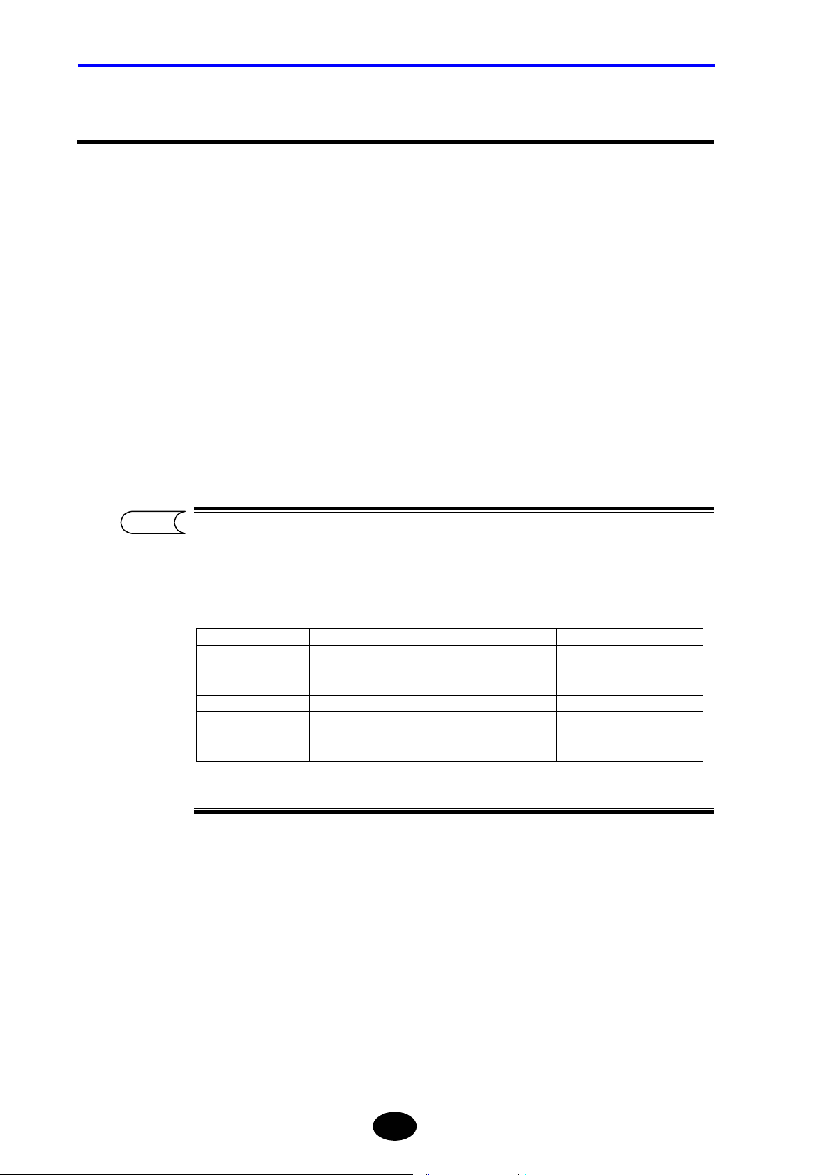
TIP
y Recommended recalibration period is 1 year. Inquiry of about recalibration,
please contact the agent from whom the instrument was purchased.
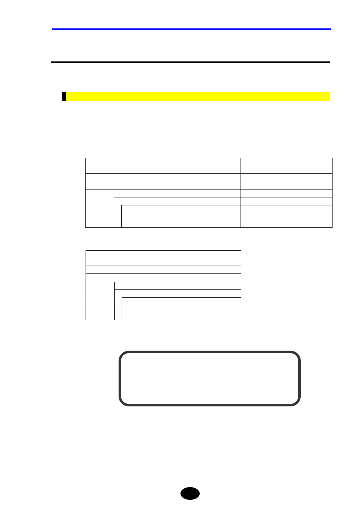
y The following parts are consumable parts and are not subject to the warranty
period.
product name Part name Life span
Liquid Crystal Display (LCD) panel 3 years
Main Frame
Optical Module Ferrule on the connector 1 year
Expansion
unit
*1: Each life span depends on the environmental conditions and frequency of use.
Battery pack 1 year
Back up battery 5 years
Printer
FDD 3 years
*1
Equivalent to 3,000 roll of
printer paper.
II
Page 4
CONVENTIONS USED IN THIS MANUAL
Conventions Used in this Manual
Safety Graphic Marks
The following graphic marks are given in this manual to ensure the safe use of this
instrument and to prevent injury and property damage. Before operating the instrument,
please read the following carefully to gain thorough understanding.
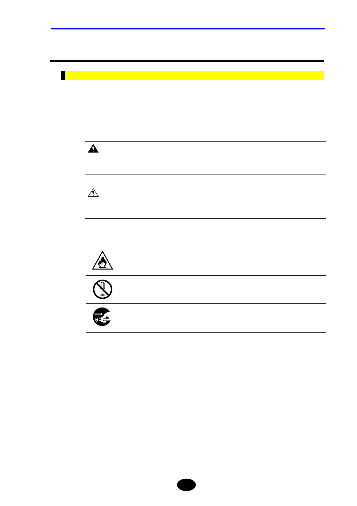
The following graphic marks indicate the degree of danger and damage that may
occur as a result of improper handling.
WARNING
Indicates a potentially hazardous situation that may possibly result in death or serious injury in the event of
improper handling.
CAUTION
Indicates a potentially hazardous situation that may result in moderate injury or property damage in the
event of improper handling.
The degree of danger and damage is indicated by the following graphic symbols.
“U” indicates a warning or caution.
This example indicates fire warning.
“{” indicates a prohibited operation.
This example indicates that disassembly is prohibited.
“z” indicates an obligatory operation.
This example indicates that the AC adapter must be removed from the power outlet.
III
Page 5
CONVENTIONS USED IN THIS MANUAL
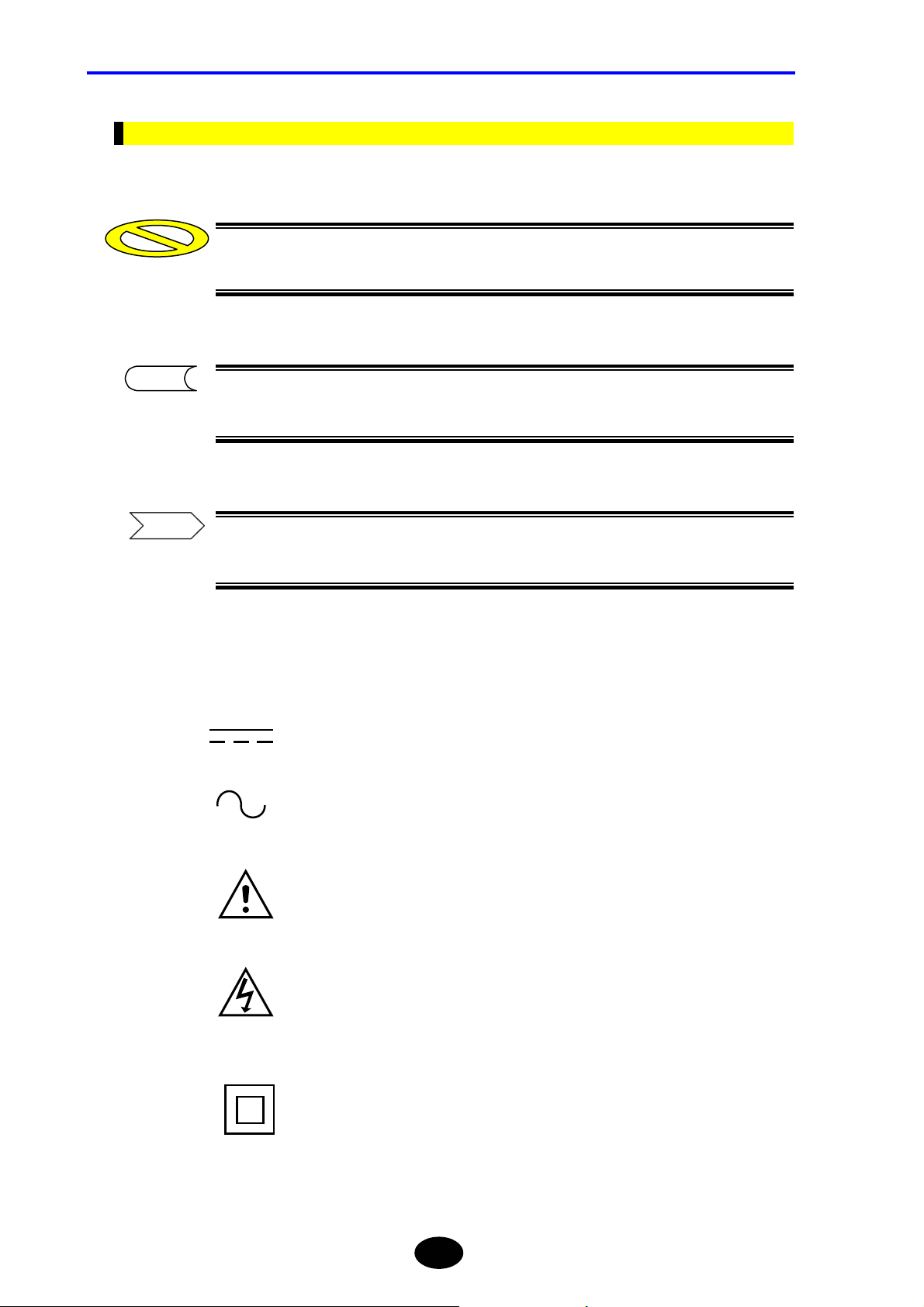
Other Graphic Marks
Caution
This is called a caution mark. It indicates an operation or procedure that requires
special care or a point to be observed regarding handling of the instrument.
TIP
This is called a TIP mark. It indicates information that is useful for operation of the
instrument.
Refer
This is called a reference mark. It indicates the reference page for the contents or
terms used in this manual.
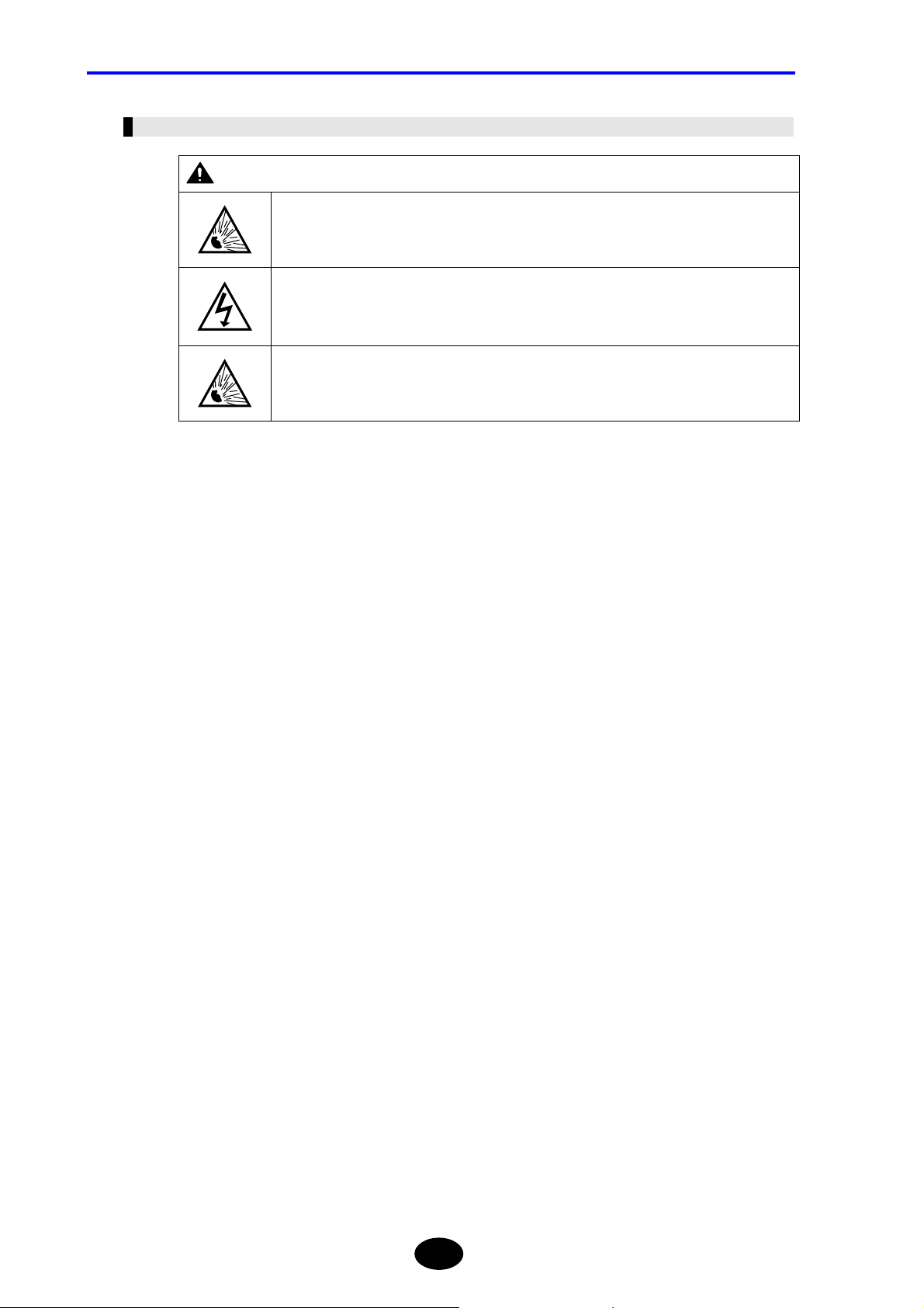
The following symbols are used on this instrument.
Direct current.
Alternating current.
Danger, Caution
Danger, risk of electronic shock.
Equipment protected throughout by DOUBLE INSULATION
or REINFORCED INSULATION
IV
Page 6
Safety Precautions
This section must be read to ensure safe use of the instrument. After reading, keep this
manual in a safe place so that it can be referred to anytime it is required.
For Safe Use of Laser Products
This instrument uses a laser light source and as such, falls into the category of “class 1M
laser product” specified by “EN60825-1:1994 +A2:2001 Safety of Laser Products-Part 1:
Equipment Classification, Requirements and User’s Guide
And the laser products comply with 21CFR1040.10 except for deviations pursuant to Laser
Notice No.50, dated May 27 2001.
Optical module AQ7261 AQ7264
Laser type FP-Laser InGaAsP FP-Laser InGaAsP
Laser class 1M 1M
Center wavelength 1310nm, 1550nm 1310nm, 1550nm
power
PULSE
CW --------------------- ≤1mW@1310nm, 1550nm Output
PULSE ≤100mW@1310nm, 1550nm ≤100mW@1310nm, 1550nm
WIDTH
”.
≤20µs@1310nm(duty:≤1.6%)
≤20µs@1550nm(duty:≤1.6%)
SAFETY PRECAUTIONS
≤20µs@1310nm(duty:≤1.6%)
≤20µs@1550nm(duty:≤1.6%)
50µs@1550nm(duty:≤0.8%)
Optical module AQ7265
Laser type FP-Laser InGaAsP
Laser class 1M
Center wavelength 1310nm, 1550nm
power
PULSE
CW ≤1mW@1310nm, 1550nm Output
PULSE ≤100mW@1310nm, 1550nm
≤20µs@1310nm(duty:≤1.6%)
WIDTH
DO NOT VIEW DIRECTLY WITH OPTICAL INSTRUMENTS
≤20µs@1550nm(duty:≤1.6%)
50µs@1550nm(duty:≤0.8%)
INVISIBLE LASER RADIATION
CLASS 1M LASER PRODUCT
V
Page 7
SAFETY PRECAUTIONS
WARNING
Invisible laser beam is output from the emitter section. The emitter section is located on the
top panel.
A message “LASER ON” is displayed while a laser beam is emitted.
Class 1M laser
invisible radiation when LASER ON.
*1
Viewing the laser output with certain optical instruments (for example, eye loupes,
magnifiers and microscopes) within a distance of 100mm may pose eye hazard.
*1: When measuring or Light source function ON
These laser beams cannot be seen by the human eye. Should the beams enter the eyes,
they may be seriously damaged, resulting in excessive deterioration of eyesight. To
prevent such accidents, the following points must be strictly observed.
• Never emit laser beam if no optical fiber is connected to the emitter section.
• When disconnecting the optical fiber from the emitter section, stop emission first.
• While laser beam is output, never stare into the emitter section nor the end of the
optical fiber that is connected to the emitter section.
Do not disassemble or modify the instrument, since high-power laser beams may be output
when doing so.
If repair is necessary due to breakdown, contact the agent from whom the instrument was
purchased. Repair is allowed by qualified personnel only.
VI
Page 8
Notes on Power Supply
The instrument can be powered by the following two methods.
• AC adapter (supplied with the instrument)
• Battery pack (Model name : 3UR18650F-2)
SAFETY PRECAUTIONS
Refer
For details on use of power supply, refer to page 3-3.
Before connecting the instrument to the power, read the safety precautions given below.
AC adapter
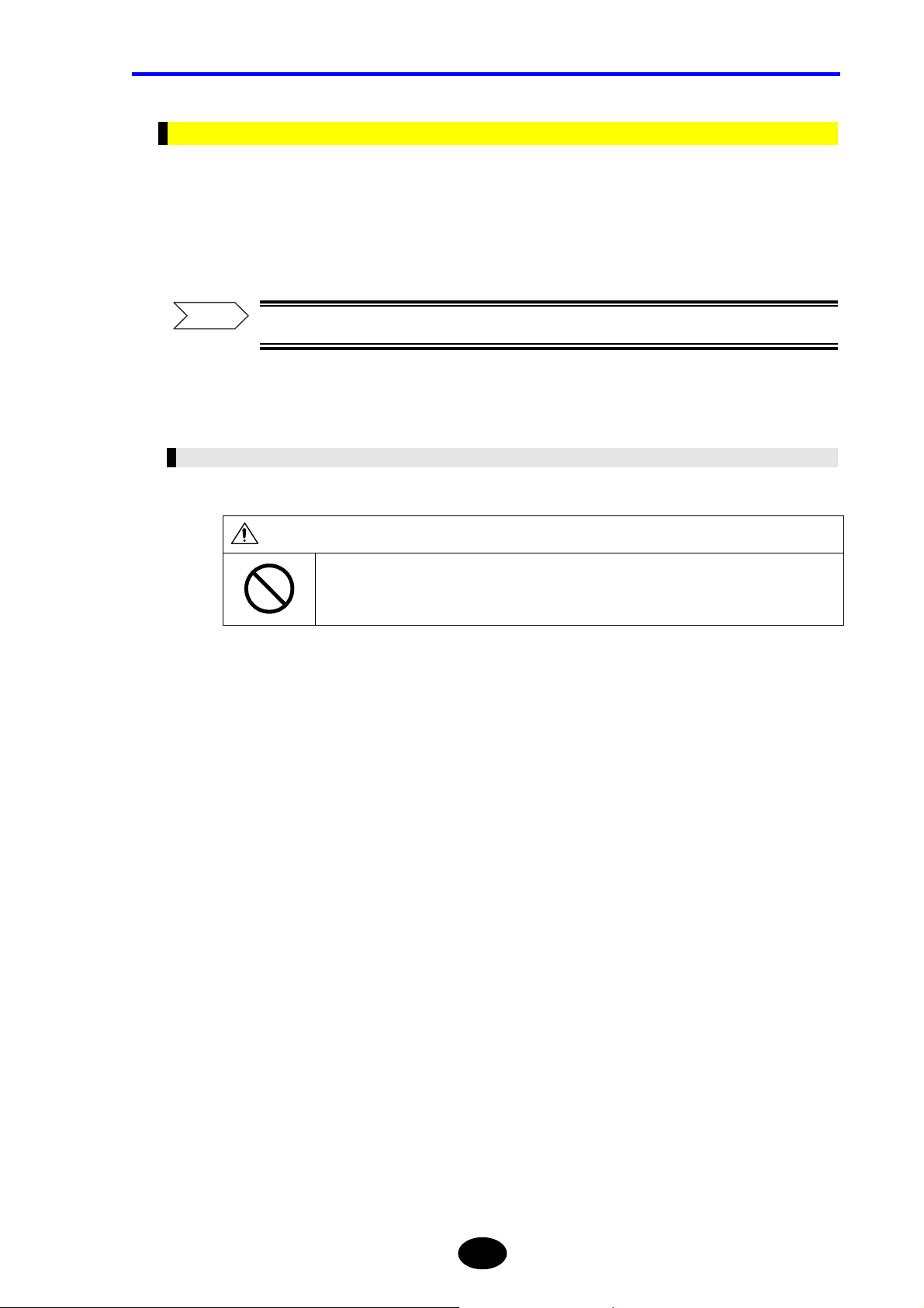
CAUTION
Do not connect or disconnect the power cord while the instrument is powered ON.
Doing so may result in breakdown.
VII
Page 9
SAFETY PRECAUTIONS
Battery Pack
WARNING
If the battery fluid leaks from the battery pack and enters the eyes, immediately wash with
clean water, such as tap water, (never rub the eyes) and consult a doctor. Failure to do so
may cause damage to the eyes.
The instrument and battery pack must be kept out of the reach of children.
If the battery fluid leaks and adheres to skin or clothes, immediately wash with clean water,
such as tap water. Adhesion to the skin may produce irritation.
VIII
Page 10
SAFETY PRECAUTIONS
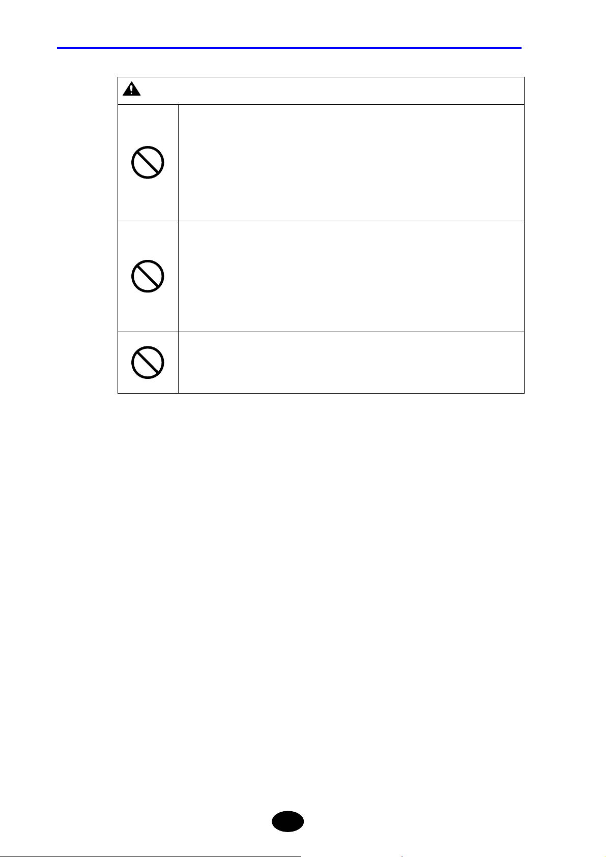
CAUTION
Do not disassemble or modify the battery pack. The battery pack has built-in safety and
protective functions designed to prevent danger. If these functions are damaged, the
battery fluid may leak from the battery pack, resulting in heat generation, smoke, explosion
or fire.
Do not connect the “+” and “−” terminals of the battery pack with metal objects like a wire.
In addition, do not carry the battery pack or store it near metal necklaces or hairpins. Doing
so may short-circuit the battery pack. This may cause excessive current flow, resulting in
leakage, heat generation, smoke, explosion or fire, or may cause the metal objects,
necklaces or hairpins to generate heat.
Do not put the battery pack into a fire or heat it. Doing so may melt insulating materials,
damage the protective circuit, or cause the battery fluid to catch fire, resulting in leakage,
heat generation, smoke, explosion or fire.
Do not use or leave the battery pack near a fire or hot objects such as stoves. Doing so
may cause short-circuit in the battery pack, resulting in battery fluid leakage, heat
generation, smoke, explosion or fire.
Do not put the battery pack under any water, including seawater, or let it get wet. If the
built-in protective circuit is damaged, the battery pack will be charged with abnormal current
or voltage. This may cause a chemical reaction inside the battery pack, resulting in battery
fluid leakage, heat generation, smoke, explosion or fire.
Do not charge the battery pack near a fire or under very hot sunshine. If it gets hot, the
protective device will initiate to prevent danger, hindering charging, or it gets damaged
causing charging with abnormal current or voltage. Such charging may cause a chemical
reaction inside the battery pack, resulting in battery fluid leakage, heat generation, smoke,
explosion or fire.
Charging of the battery pack must be performed on this instrument under the specified
charging conditions. If charging is performed in an environment that does not conform to
the specified charging conditions (e.g. at excessively high temperatures, with higher
voltage/current than the specified, using a modified charger), the battery pack may be
excessively charged, or charged with abnormal current. Such charging may cause an
abnormal chemical reaction inside the battery pack, resulting in battery fluid leakage, heat
generation, smoke, explosion or fire.
Do not pierce the battery pack with a nail, hit it with a hammer, or stamp on it. Doing so
may damage or deform the battery pack. This may cause short-circuit inside the battery
pack, resulting in battery fluid leakage, heat generation, smoke, explosion or fire.
Do not cause any excessive impact to the battery pack or throw it. Doing so may result in
battery fluid leakage, heat generation, smoke, explosion or fire.
Furthermore, if the built-in protective circuit is damaged, the battery pack will be charged
with abnormal current or voltage. This may cause an abnormal chemical reaction inside the
battery pack, resulting in battery fluid leakage, heat generation, smoke, explosion or fire.
Do not solder directly on the battery pack. Doing so may melt insulating materials, damage
the protective circuit, resulting in battery fluid leakage, heat generation, smoke, explosion
or fire.
Do not use the battery pack if it shows excessive damage or deformation. Using it in such
condition may result in battery fluid leakage, heat generation, smoke, explosion or fire.
IX
Page 11
SAFETY PRECAUTIONS
CAUTION
The battery pack must only be used for this instrument.
If charging is not complete even if the specified charging time has elapsed, stop charging.
Continuing to charge the battery pack may result in battery fluid leakage, heat generation,
smoke, explosion or fire.
Do not put the battery pack in a microwave oven or high-pressure container. The battery
pack may be heated rapidly or may no longer be airtight, resulting in battery fluid leakage,
heat generation, smoke, explosion or fire.
If battery fluid leakage or an odd smell is detected, immediately take the battery pack away
from the heat source. Leaving it in such condition may cause the battery fluid to catch fire,
resulting in smoke, explosion or fire.
If odd smells, heat generation, discoloration or deformation are noticed during use,
charging or storage of the battery pack, disconnect it from the instrument or charger, and
do not use it. Continuing to use it in such conditions may result in battery fluid leakage,
heat generation, smoke, explosion or fire.
Do not use or leave the battery pack in strong direct sunlight or in places like inside an
automobile under very strong sunshine. Doing so may result in battery fluid leakage, heat
generation or smoke. It also may deteriorate the performance or life of the battery pack.
The battery pack has a built-in protective circuit designed to prevent danger. So, do not use
the battery pack in places where static electricity that is likely to damage the protective
device is generated. Using the battery pack in such places may damage the protective
device, resulting in battery fluid leakage, heat generation, smoke, explosion or fire.
The battery pack can be charged in the following temperature range. Charging the battery
pack outside this range may cause battery fluid leakage, heat generation or breakdown. It
may also deteriorate the performance or life of the battery pack. Allowed charging
temperature range: 5°C to 30°C
If rust, odd smells, heat generation or any other abnormality are found when using the
instrument for the first time following purchase, stop its use and contact the agent from
whom the instrument was purchased.
X
Page 12
Notes on Operating Environment and Conditions
Restrictions Regarding Operating Environment
WARNING
Take care not to let water enter the instrument or to allow it to get wet.
Failure to observe this may result in fire, electric shock or breakdown.
Restrictions Regarding Operating Conditions
WARNING
The power cord specified by YOKOGAWA must be used.
SAFETY PRECAUTIONS
Use of any other power cord may result in fire, electric shock or accident.
XI
Page 13
SAFETY PRECAUTIONS
Notes on Installation
For Personnel Performing Installation
WARNING
CAUTION
Do not connect the instrument to an AC outlet using an extension power cord.
Doing so may result in heat generation or fire.
Do not dissemble or modify the instrument.
Doing so may result in electric shock, fire or accident.
Do not expose the instrument to water splashes.
Failure to observe this may result in electric shock, fire or accident.
Do not allow the terminals to short-circuit.
Failure to observe this may result in fire or breakdown.
When using an AC adapter, make sure that it is inserted into the AC outlet properly.
If the power plug comes into contact with metal objects, fire or electric shock may result.
When carrying out work with the instrument on your shoulders, take care not to let it drop.
Failure to observe this may result in injury or breakdown.
XII
Page 14
SAFETY PRECAUTIONS
Restricted and Prohibited Items Regarding Operating Environment and
Conditions
WARNING
Do not insert metal bars or such like into gaps on the instrument.
Doing so may result in fire, electric shock or accident.
CAUTION
Keep the power cord away from heaters etc.
Failure to observe this may result in electric shock.
Do not connect or disconnect the power plug with wet hands.
Doing so may result in electric shock.
Do not place the instrument in humid or dusty areas.
Doing so may result in electric shock or breakdown.
Do not place the instrument on an unstable surface like a shaky table or slope.
The instrument may drop or turn over, causing injury.
Do not place the instrument in areas where there is excessive vibration or impact.
The instrument may drop or turn over, causing injury.
When disconnecting the power cord, always hold the plug and pull it out.
Pulling the power cord may damage the cord, resulting in fire or electric shock.
Do not place the instrument in direct sunlight or in places like inside a car under the very
hot sunshine.
Placing the instrument in such places may cause the temperature inside the instrument to
rise, resulting in breakdown.
XIII
Page 15
SAFETY PRECAUTIONS
Prohibited Items Regarding Installation Method
WARNING
CAUTION
Notes on Handling
Do not place heavy objects on the power cord, heat or pull it, and do not modify the power
cord.
Doing so may damage the cord, resulting in fire or electric shock.
Before transferring the instrument to another site, make sure that the power plug is
removed from the AC outlet and all the external connecting cables are disconnected.
Failure to observe this may damage the cord, resulting in fire or electric shock.
The instrument must be handled according to the procedures given in this manual.
Warning marks (“WARNING”, “CAUTION”) must be strictly observed.
WARNING
Do not leave metal objects or containers of liquid, such as water, near the instrument.
Strong wind may turn over the container spilling the water or cause metal objects to hit the
instrument, resulting in fire, electric shock or breakdown.
Do not modify the power cord, bend, twist or pull it excessively.
Failure to observe this may result in fire or electric shock.
Before plugging in or removing connectors from the instrument, make sure that the
instrument is powered OFF.
Failure to observe this may result in fire, electric shock or breakdown.
Do not disassemble or modify the instrument.
Doing so may result in fire, electric shock or accident.
Do not allow the terminals of the battery pack to get wet.
Failure to observe this may result in rust, fire or electric shock.
XIV
Page 16
SAFETY PRECAUTIONS
CAUTION
When closing panels and covers, take care not to trap your fingers.
If you are not going to use the instrument for a long period of time, the power plug must be
removed from the AC outlet for safety reasons. It must also be removed in the event of
thunderstorms.
Failure to observe this may result in fire, electric shock or breakdown.
Do not use the instrument at -10°C or lower temperatures.
Operation of the indicators cannot be guaranteed.
Do not allow short-circuiting of the battery pack’s terminals with metal objects.
Failure to observe this may result in fire or breakdown.
Caution
If this instrument is used in a manner not specified in this manual, the protection
provided by this instrument may be impaired.
Notes on Maintenance and Inspection
Periodic maintenance and inspection of the instrument are recommended. For enquiries
regarding maintenance and inspection, contact the agent from whom the instrument was
purchased.
CAUTION
Take care not to let dust or dirt collect inside the instrument.
Collection of dust or dirt inside the instrument may result in fire or breakdown.
XV
Page 17
SAFETY PRECAUTIONS
Actions to be Taken in Case of Abnormalities
WARNING
Do not repair the instrument even though the instrument becomes faulty.
Doing so may result in electric shock or injury. In addition, the instrument repaired by the
user without permission will be exempt from the warranty.
Should the instrument be dropped or damaged, turn OFF the power switch on the
instrument, disconnect the power plug from the AC outlet and then contact your agent from
whom the instrument was purchased.
Continuing to use it may result in fire, electric shock or breakdown.
Should foreign items enter the instrument, turn OFF the power switch on the instrument,
disconnect the power plug from the AC outlet and then contact your agent from whom the
instrument was purchased.
Continuing to use it may result in fire, electric shock or breakdown.
Should smoke or odd smells be detected, turn OFF the power switch on the instrument,
disconnect the power plug from the AC outlet and then contact your agent from whom the
instrument was purchased.
Failure to observe this may result in fire, electric shock or breakdown.
If the power cord is damaged, contact the agent for replacement.
Continuing to use it may result in fire or electric shock.
Notes on Disposal
WARNING
When disposing of the instrument, do not put it into a fire.
Doing so may cause explosion, resulting in fire or burns.
CAUTION
The instrument uses a lithium battery for memory backup and a gallium arsenide battery
for the light source module. In addition, the liquid crystal display panel contains fluorescent
tubes.
So, disposal of the instrument must be carried out according to the laws and regulations of
the country and local authorities.
XVI
Page 18
Other Precautions
Notes on Backup Battery
CAUTION
SAFETY PRECAUTIONS
The instrument uses a lithium battery for memory backup. The instrument may malfunction
suddenly due to battery life, therefore, early replacement of the battery is recommended.
The life of the battery is approximately five years.
Refer
For details on replacement of the backup battery, refer to page 1-25.
Notes on LCD Panel
CAUTION
This instrument uses a liquid crystal display panel. The display panel gradually becomes
unclear due to the backlight life. The LCD panel needs to be replaced when it becomes
unclear.
The life of the LCD panel is approximately three years.
Please contact the agent when the panel is no longer clear.
XVII
Page 19

CONTENTS
Structure of this Manual
Chapter 1 BEFORE USING THE INSTRUMENT
Explains the names and functions of each part of the instrument, and how to carry out
daily maintenance.
Chapter 2 BEFORE STARTING MEASUREMENT
Explains how to set up the instrument.
Chapter 3 PERFORMING MEASUREMENTS
Explains how to set measurement conditions and how to measure optical fiber cables.
Chapter 4 ENTERING CHARACTERS
Explains how to enter label and file names.
Chapter 5 EDITING AUTOMATIC SEARCH RESULTS
The instrument has a function that detects events in the measurement results
automatically at the end of measurement. This chapter explains how to edit the detection
results.
Chapter 6 FILE OPERATION
Explains how to use (e.g. open, delete) files saved to a storage medium.
Chapter 7 USING USEFUL FUNCTIONS
This instrument has various useful functions. This chapter explains these functions.
Chapter 8 USING OPTIONS AND EXTERNAL DEVICES
Explains how to use options and external devices (e.g. USB printer) and how to control the
instrument from a personal computer.
Chapter 9 SPECIFICATIONS
Explains the specification of the instrument itself, optical module and options.
Chapter 10 APPENDIX
Explains corrective actions to be carried out in case of breakdown. Also provides a list of
technical terms regarding the instrument.
XVIII
Page 20

CONTENTS
Contents
Preface..................................................................................................... I
Warranty................................................................................................. II
Conventions Used in this Manual ....................................................... III
Safety Graphic Marks .............................................................................................................III
Other Graphic Marks .............................................................................................................IV
Safety Precautions ................................................................................V
For Safe Use of Laser Products ............................................................................................. V
Notes on Power Supply ........................................................................................................ VII
Notes on Operating Environment and Conditions.................................................................. XI
Notes on Installation ............................................................................................................. XII
Other Precautions...............................................................................................................XVII
Structure of this Manual...................................................................XVIII
Chapter 1 BEFORE USING THE INSTRUMENT............................................................ XVIII
Chapter 2 BEFORE STARTING MEASUREMENT......................................................... XVIII
Chapter 3 PERFORMING MEASUREMENTS................................................................ XVIII
Chapter 4 ENTERING CHARACTERS ...........................................................................XVIII
Chapter 5 EDITING AUTOMATIC SEARCH RESULTS .................................................. XVIII
Chapter 6 FILE OPERATION..........................................................................................XVIII
Chapter 7 USING USEFUL FUNCTIONS.......................................................................XVIII
Chapter 8 USING OPTIONS AND EXTERNAL DEVICES.............................................. XVIII
Chapter 9 SPECIFICATIONS.......................................................................................... XVIII
Chapter 10 APPENDIX ...................................................................................................XVIII
Contents..............................................................................................XIX
Chapter 1 BEFORE USING THE INSTRUMENT .............................. 1-1
1.1 What is the AQ7260? .................................................................................1-2
1.2 Installation, Storage and Transport..........................................................1-3
Unpacking and Receiving Inspection................................................................................... 1-3
Notes on Storage................................................................................................................. 1-4
Notes on Transport..............................................................................................................1-5
1.3 Power Supply.............................................................................................1-7
XIX
Page 21

CONTENTS
1.4 Daily Maintenance.....................................................................................1-8
Cleaning the Exterior of the Instrument ................................................................................ 1-8
Cleaning the Optical Connector ...........................................................................................1-9
Cleaning the Optical Adapter.............................................................................................. 1-11
1.5 Replacing the Optical Module................................................................1-12
Removing the Optical Module ............................................................................................1-12
Attaching a New Optical Module ........................................................................................ 1-14
1.6 Replacing the Optical Adapter ...............................................................1-16
Removing the Optical Adapter............................................................................................1-16
Attaching a New Optical Adapter........................................................................................1-17
1.7 Replacing the Battery Pack....................................................................1-19
Removing the Battery Pack................................................................................................1-19
Attaching a New Battery Pack............................................................................................1-21
1.8 Charging the Battery Pack ..................................................................... 1-23
1.9 Replacing the Backup Battery................................................................1-25
1.10 Names of Instrument Parts..................................................................... 1-28
Front View ..........................................................................................................................1-28
Rear View...........................................................................................................................1-30
Top View.............................................................................................................................1-32
Right Side View..................................................................................................................1-33
Accessories........................................................................................................................1-34
Options...............................................................................................................................1-35
1.11 Screen Display.........................................................................................1-36
Description of Screen Display ............................................................................................1-36
Meaning of Each Part of the Trace..................................................................................... 1-40
1.12 Notes Before Performing Measurement................................................ 1-42
When Using AQ7261 / AQ7264 / AQ7265..........................................................................1-42
Chapter 2 BEFORE STARTING MEASUREMENT ...........................2-1
2.1 Changing System Settings.......................................................................2-2
Displaying the Setting Change Window ...............................................................................2-3
Changing Settings................................................................................................................2-4
Restoring the Default System Settings............................................................................... 2-38
Chapter 3 PERFORMING MEASUREMENTS...................................3-1
3.1 Flow of Measurement Steps..................................................................... 3-2
3.2 Turning ON the Power [Step 1].................................................................3-3
When Using AC Power.........................................................................................................3-4
When Using the Battery Pack ..............................................................................................3-5
XX
Page 22

CONTENTS
3.3 Warming Up the Instrument [Step 2]........................................................3-6
3.4 Connecting an Optical Fiber to the Instrument [Step 3] ......................3-7
Cleaning the Optical Connector and Adapter....................................................................... 3-7
Connecting the Optical Fiber ............................................................................................... 3-8
3.5 Setting the Measurement Conditions/Auto Search Conditions
[Step 4] .......................................................................................................3-9
Displaying the Measurement Condition Change Window .................................................. 3-10
Changing the Measurement Conditions ............................................................................ 3-12
Changing the Measured Data Auto Saving Conditions...................................................... 3-33
Changing the Auto Search Conditions............................................................................... 3-35
Notes on Changing of Measurement Conditions / Auto Search Conditions ....................... 3-50
Restoring the Default Measurement Conditions / Auto Search Conditions ........................ 3-52
3.6 Setting the File Name/Location to Store the File [Step 5].....................3-53
3.7 Measuring an Optical Fiber [Step 6].......................................................3-54
Performing Real Time Measurement................................................................................. 3-55
Performing Average Measurement .................................................................................... 3-56
When the Trace Contains a Lot of Noise........................................................................... 3-59
3.8 Checking the Measured Data [Step 7]....................................................3-64
Basic Operations ............................................................................................................... 3-64
When “AUTO” is Selected for “EVENT SEARCH” ............................................................. 3-68
When “MANUAL” is Selected for “EVENT SEARCH” ........................................................ 3-71
3.9 Recording the Measured Data [Step 8] ..................................................3-88
Saving the Measured Data ................................................................................................ 3-88
Printing the Measured Data ............................................................................................. 3-104
3.10 Turning OFF the Power [Step 9] ...........................................................3-107
Turning OFF the Power ................................................................................................... 3-107
Disconnecting the Optical Fiber....................................................................................... 3-108
Chapter 4 ENTERING CHARACTERS.............................................. 4-1
4.1 Entering Characters...................................................................................4-2
Displaying the Label Input Window...................................................................................... 4-3
Entering a Label .................................................................................................................. 4-4
4.2 Editing Characters.....................................................................................4-7
Deleting a Character............................................................................................................4-7
Changing a Character ......................................................................................................... 4-8
Adding a Character..............................................................................................................4-9
Chapter 5 EDITING AUTOMATIC SEARCH RESULTS.................... 5-1
5.1 Editing an Event .........................................................................................5-2
XXI
Page 23

CONTENTS
Inserting an Event ................................................................................................................5-3
Deleting an Event.................................................................................................................5-6
Moving an Event ..................................................................................................................5-9
5.2 Editing an Event Marker ......................................................................... 5-12
5.3 Editing the Event List..............................................................................5-15
Displaying the List Edit Window .........................................................................................5-16
Editing the Event List..........................................................................................................5-18
5.4 Attaching a Comment to an Event.........................................................5-23
5.5 Changing the Conditions and Performing Auto Search Again............5-25
Displaying the Auto Search Condition Change Window..................................................... 5-26
Changing the Auto Search Conditions................................................................................5-28
Notes on Changing of Auto Search Conditions ..................................................................5-38
Chapter 6 FILE OPERATION.............................................................6-1
6.1 File Operation............................................................................................6-2
Saving a File ........................................................................................................................6-2
Recalling a File.....................................................................................................................6-3
Deleting a File ......................................................................................................................6-7
Printing a File .....................................................................................................................6-12
Copying a File ....................................................................................................................6-18
6.2 Using the Utility Functions.....................................................................6-22
Initializing a Drive ...............................................................................................................6-23
Deleting a Folder................................................................................................................6-25
Creating a Folder ...............................................................................................................6-27
Copying a Folder................................................................................................................6-30
Chapter 7 USING USEFUL FUNCTIONS..........................................7-1
7.1 Initializing the Vertical-/Horizontal-Axis Scales......................................7-2
7.2 Displaying Approximate Lines.................................................................7-3
For Traces that Have Been Auto Searched ..........................................................................7-4
For Traces that Have Not Been Auto Searched ...................................................................7-6
7.3 Using the Cursor Link Function...............................................................7-7
For Traces that Have Been Auto Searched ..........................................................................7-8
For Traces that Have Not Been Auto Searched .................................................................7-10
7.4 Using the Label Fixed Form Input Function.......................................... 7-11
7.5 Using the Label Auto Increment Function ............................................7-13
7.6 Entering Various Information for the Measured Trace......................... 7-16
Displaying the Detailed Information Input Window .............................................................7-17
Entering Detailed Information.............................................................................................7-18
XXII
Page 24

CONTENTS
7.7 Changing the Distance Reference ..........................................................7-27
For Traces that Have Been Auto Searched ....................................................................... 7-28
For Traces that Have Not Been Auto Searched................................................................. 7-31
7.8 Using the Event Fix Function .................................................................7-33
7.9 Using the Section Analysis Function.....................................................7-36
7.10 Manipulating Two or More Traces ..........................................................7-39
Displaying Multiple Traces................................................................................................. 7-40
Displaying the Subtract Trace of Two Traces..................................................................... 7-43
Merging Two Traces .......................................................................................................... 7-45
7.11 Using the Light Source Function............................................................7-47
Displaying the Light Source Function Window................................................................... 7-48
Changing the Wavelength and Modulation Frequency ...................................................... 7-49
Emitting a Laser................................................................................................................. 7-51
Turn off a Laser ................................................................................................................. 7-51
7.12 Making a Measurement Continuously Changing the Wavelengths.....7-52
Chapter 8 USING OPTIONS AND EXTERNAL DEVICES................ 8-1
8.1 Using Options ............................................................................................8-2
Option Unit........................................................................................................................... 8-3
8.2 Using External Devices.............................................................................8-9
USB Keyboard................................................................................................................... 8-10
PCMCIA Memory Card...................................................................................................... 8-13
USB Printer........................................................................................................................ 8-16
USB Storage Medium........................................................................................................ 8-21
8.3 Operating the Instrument from a Personal Computer..........................8-22
Operation by using RS-232C............................................................................................. 8-23
Operation by using GP-IB.................................................................................................. 8-29
Control Commands............................................................................................................ 8-35
Request Commands.......................................................................................................... 8-47
Return Value Format.......................................................................................................... 8-59
Command Input Examples (RS-232C) .............................................................................. 8-61
Chapter 9 SPECIFICATIONS ............................................................ 9-1
9.1 Specifications of main frame....................................................................9-2
9.2 Specifications of optical modules............................................................9-4
9.3 Specifications of optional units................................................................9-7
9.4 Outside view drawings..............................................................................9-8
AQ7260 OTDR .................................................................................................................... 9-9
AQ7261 SMF MODULE..................................................................................................... 9-10
XXIII
Page 25

CONTENTS
AQ7264 SMF MODULE ..................................................................................................... 9-11
AQ7265 SMF MODULE .....................................................................................................9-12
PRINTER/FDD UNIT..........................................................................................................9-13
PRINTER UNIT ..................................................................................................................9-14
Chapter 10 APPENDIX ....................................................................10-1
10.1 Software Upgrade....................................................................................10-2
10.2 Troubleshooting ......................................................................................10-5
When the Instrument Appears Faulty................................................................................. 10-5
When the Problem Cannot Be Solved................................................................................ 10-7
10.3 Glossary...................................................................................................10-8
Attenuation .........................................................................................................................10-8
Attenuation dead zone .......................................................................................................10-8
Back scattering ray.............................................................................................................10-8
Connection point ................................................................................................................10-9
Dead zone..........................................................................................................................10-9
Distance measuring accuracy ............................................................................................10-9
Distance range ...................................................................................................................10-9
Dynamic range .................................................................................................................10-10
Event dead zone ..............................................................................................................10-10
Event list...........................................................................................................................10-10
Event note ........................................................................................................................10-10
Far end............................................................................................................................. 10-11
Fault location.................................................................................................................... 10-11
Filter ................................................................................................................................. 10-11
Format.............................................................................................................................. 10-11
Fresnel reflection.............................................................................................................. 10-11
Group index......................................................................................................................10-12
Label ................................................................................................................................10-12
Least squares approximate (LSA).................................................................................... 10-12
Near end ..........................................................................................................................10-12
OTDR ............................................................................................................................... 10-12
Pulse width.......................................................................................................................10-13
Real time measurement ...................................................................................................10-13
Reflection point ................................................................................................................10-13
Resolution ........................................................................................................................10-13
Return loss .......................................................................................................................10-14
S/N ...................................................................................................................................10-14
Sampling count ................................................................................................................10-14
Sampling resolution.......................................................................................................... 10-14
XXIV
Page 26

CONTENTS
Secondary reflection........................................................................................................ 10-15
Spatial resolution ............................................................................................................. 10-15
Splice loss........................................................................................................................ 10-15
Two Point Approximate (TPA) .......................................................................................... 10-15
XXV
Page 27

Page 28

Chapter 1
BEFORE USING THE INSTRUMENT
1.1 What is the AQ7260? ............................................................................................... 1-2
1.2 Installation, Storage and Transport........................................................................... 1-3
1.3 Power Supply...........................................................................................................1-7
1.4 Daily Maintenance.................................................................................................... 1-8
1.5 Replacing the Optical Module................................................................................. 1-12
1.6 Replacing the Optical Adapter................................................................................1-16
1.7 Replacing the Battery Pack.................................................................................... 1-19
1.8 Charging the Battery Pack...................................................................................... 1-23
1.9 Replacing the Backup Battery................................................................................ 1-25
1.10 Names of Instrument Parts..................................................................................... 1-28
1.11 Screen Display....................................................................................................... 1-36
1.12 Notes Before Performing Measurement................................................................. 1-42
Page 29

Chapter 1 BEFORE USING THE INSTRUMENT
1.1 What is the AQ7260?
This instrument emits a light pulse into an optical fiber and searches faults from the end of
the fiber, then calculates transmission loss effectively by detecting back scattering rays
caused by Rayleigh scattering inside the fiber, and rays reflecting at connection points and
fault points.
Since the optical section comes in a module, an appropriate optical module can be
selected according to the wavelength and type of optical fiber to be used.
This instrument also can be used for light source depend on the mounted optical module.
1-2
Page 30

Chapter 1 BEFORE USING THE INSTRUMENT
1.2 Installation, Storage and Transport
This section explains points to be observed when installing, storing or transporting the
instrument.
Unpacking and Receiving I n spection
Prior to shipment, the instrument has undergone strict mechanical and electrical
inspection to ensure its correct operation. On delivery, immediately unpack and check the
instrument for any damage that might have occurred during transport.
Mechanical Inspection
After the instrument is unpacked, check the appearance, operation of each switch and
connector, and check for any damage or defects that might have occurred during
transport. In addition check that all the accessories are present and correct.
TIP
It is recommended that packing materials, such as corrugated boxes and
cushioning materials, be kept in a safe place so that they can be reused when
transporting the instrument again.
Operation Inspection
If no defects are found by mechanical inspection, check the instrument to see whether it
conforms to the specifications.
When Damage or Defects are Found
If damage or non-conformation to the specifications is found during mechanical or
operation inspection, contact the agent from whom the instrument was purchased.
1-3
Page 31
Chapter 1 BEFORE USING THE INSTRUMENT
Notes on Storage
This section explains points to be observed when storing the instrument for a long period
of time.
Notes Before Storage
Dust, fingerprints, dirt and stains etc. collected on the instrument must be wiped off with a
piece of cloth.
Carry out operation inspection to check that the instrument operates correctly.
Refer
For the method of cleaning the exterior of the instrument, refer to page 1-8.
Storage Conditions
When storing the instrument, make sure it is stored under the following environmental
conditions.
• Temperature −20 to 60°C
• Humidity 95%RH or less (No condensation allowed)
• Temperature/humidity does not change excessively throughout the day.
• Areas where the instrument will not be exposed to direct sunlight
• Areas where there is little dust
• Low-humidity areas where no water drops are generated or collect on the instrument
• Areas where the instrument will not be exposed to active gases or oxidized.
Caution
Refer
If you are not going to use the instrument for a long period of time, store it with the
battery pack removed. Furthermore, when storing the instrument outside the above
temperature range, make sure that the battery pack is removed.
For the method of removing the battery pack, refer to page 1-19.
Notes When Re-Using the Instrument
When using the instrument again after storing it for a long period of time, first carry out
operation inspection to check that the instrument operates correctly.
1-4
Page 32

Notes on Transport
This section explains points to be observed when transporting the instrument.
Repacking
To repack the instrument, the packing materials used to deliver the instrument must be
used. If they have been discarded or damaged, pack the instrument as explained below.
1. Wrap the instrument with a thick vinyl sheet to prevent entry of dust.
2. Place cushioning material on projecting parts on the bottom and front/rear
panels of the instrument to protect them.
3. Prepare a corrugated, wooden or aluminum box that is large enough to
accommodate the instrument and allows 10 to 15 cm space between the surface
of each part of the instrument (top, bottom, front, rear, right/left panels) and the
sides of the box.
Chapter 1 BEFORE USING THE INSTRUMENT
4. Put shock-absorbent materials at the bottom of the box to absorb shocks, such
as vibration.
5. Place the instrument in the center of the box and fill the spaces (between the
box’s internal surface and each surface of the instrument: top, front, rear,
right/left panels) with shock absorbent materials.
6. Secure the outside of the box with packing cord, adhesive tape or bands.
Caution
TIP
The instrument must be packed so that any impact or vibration on the instrume nt is
50G or less. If the instrument is exposed to impact or vibration exceeding 50G, the
instrument may get damaged. In particular, take care not to let any excessive
pressure be exerted on the LCD.
It is recommended that packing materials used to deliver the instrument be kept in
a safe place. Using these materials will facilitate packing work when transporting
the instrument.
1-5
Page 33

Chapter 1 BEFORE USING THE INSTRUMENT
Transport
During transport, make sure that vibration is avoided and the required storage conditions
are satisfied.
Refer
Caution
For details on the storage conditions, refer to pa ge 1-4.
When the battery pack is transport by using aircraft. Pleas each package contains
12 battery pack or less. However, airlines refuse transport battery packs. Please
inquire to the airline in advance.
1-6
Page 34

1.3 Power Supply
The instrument can run on AC power (AC battery is supplied with the instrument) or
battery pack.
The AC adapter must be connected to an AC power outlet (100 to 240 V, 50/60Hz).
Necessary measures must be taken to prevent the following.
• Accident by electric shock
• Internal damage of the instrument by abnormal voltage
Chapter 1 BEFORE USING THE INSTRUMENT
1-7
Page 35

Chapter 1 BEFORE USING THE INSTRUMENT
1.4 Daily Maintenance
The instrument can be used for many years if daily maintenance is carried out properly.
Daily maintenance is also important to prevent trouble and breakdowns.
This section explains how to clean the following items.
• Exterior of the instrument
• Optical connector
• Optical adapter
Cleaning the Exterior of the Instrument
Wet a cloth with lukewarm water, squeeze it thoroughly, wipe the LCD and exterior of the
instrument with it, and then wipe the instrument with dry cloth.
Caution
•Before carrying out daily maintenance, make sure that the power is turned OFF.
•Do not use chemicals such as thinner, benzene and alcohol. Use of such
chemicals may cause deterioration or discoloration of the exterior of the instrument.
•To prevent entry of water into the instrument, the wet cloth must be firmly
squeezed before it is used to wipe the exterior.
1-8
Page 36

Cleaning the Optical Connector
The end of the optical connector must be kept clean at all times. Collection of dust or dirt
on the end may damage the optical adapter of the instrument, hindering correct
measurement.
This section explains how to clean the end of the optical connector by taking a FC
connector as an example.
1. Place the end of the optical connector perpendicular to the cleaner’s cleaning
surface.
2. With the end of the optical connector pushed against the cleaning surface, turn
it approximately one turn.
3. Then, slide the end of the optical connector.
Chapter 1 BEFORE USING THE INSTRUMENT
4. Repeat steps 2 to 3 to clean the end of the optical connector.
Caution
When cleaning the optical connector, make sure that it is pushed against the
cleaner firmly. If not, the optical connector may not be cleaned sufficiently.
1-9
Page 37

Chapter 1 BEFORE USING THE INSTRUMENT
TIP
•To check the condition of the end of the optical connector, use of a surface check
microscope (x200 to x400) is helpful.
•Various cleaners designed for optical fiber cables are available, including
“OPTICAL FIBER CONNECT OR CLEANER” man ufa ctured by NTT-ME.
CLETOP reel-type A SC, FC, ST, DIN, D4
CLETOP reel-type B MT, Biconic
CLETOP spare tape ---------CLETOP stick-type ----------
Product Name Appropriate Connector Types
1-10
Page 38

Cleaning the Optical Adapter
This section explains how to clean the optical adapter.
1. Make sure that the power to the instrument is turned OFF.
WARNING
Never clean the instrument if the power is ON. Laser beams are invisible to the naked
eye, but if they enter the eyes, they may cause impaired eyesight.
Use of controls or adjustments or performance of procedures other than those specified
herein may result in hazardous radiation exposure.
Chapter 1 BEFORE USING THE INSTRUMENT
Refer
For the method of turning OFF the power , refer to page 3-107.
2. Slide the optical connector cover on the top of the instrument to open it.
3. Clean the outer surface inside the optical adapter using a special cleaning stick.
Also clean the end of the optical fiber with a special cleaning stick.
Special cleaner
CLETOP
Stick-Type
Cover of
optical fiber
cable connector
Front shell
TIP
Various cleaners designed for optical adapters are available, including “CLETOP
Stick-Type” manufactured by NTT-ME.
1-11
Page 39
Chapter 1 BEFORE USING THE INSTRUMENT
1.5 Replacing the Optical Module
This section explains how to replace the optical module with a new one.
Removing the Optical Module
Caution
Refer
The optical module cannot be replaced if the expansion unit is conn ected.
For the method of removing the expansion unit, refer to page 8-5.
1. Make sure that the power to the instrument is turned OFF.
WARNING
Do not replace the optical module while the instrument is powered ON.
Failure to observe this may result in electric shock or breakdown.
Refer
For the method of turning OFF the power , refer to page 3-107.
1-12
Page 40

Chapter 1 BEFORE USING THE INSTRUMENT
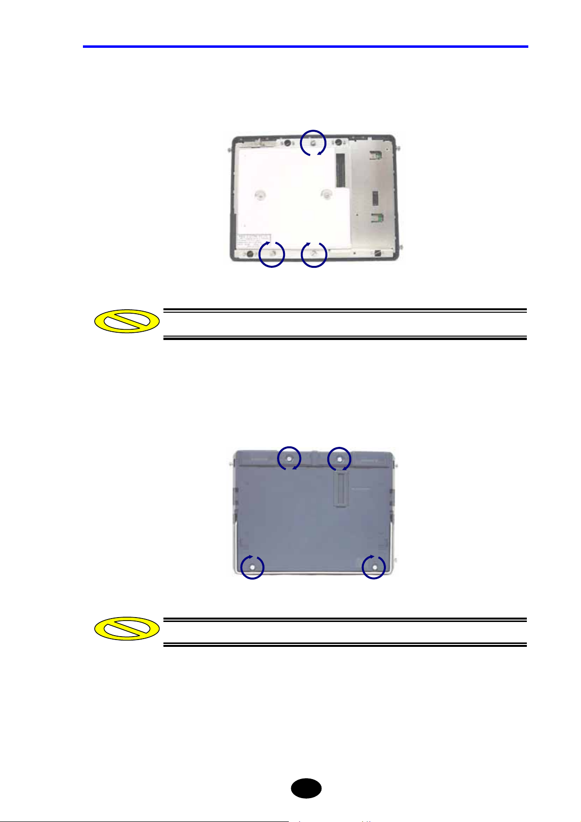
2. Remove the optical module cover.
Loosen the four screws shown below counter-clockwise.
3. Lift the optical module cover straight to remove it.
4. Remove the optical module.
Loosen the three screws shown below counter-clockwise. Then, pull out the optical
module as shown below to remove it.
knob
knob
CAUTION
OPTICAL
MODULE
When removing the optical module, lift the two knobs slowly at the same time to detach
them. Never shake it sideways or remove it by force.
Doing so may damage the connector.
Take care not to touch the connector on the optical module or the one on the instrument.
Doing so may result in breakdown.
1-13
Page 41
Chapter 1 BEFORE USING THE INSTRUMENT
Attaching a New Optical Module
This section explains how to attach a new optical module. It is assumed that the optical
module and its cover have been removed.
1. Make sure that the power to the instrument is turned OFF.
WARNING
Do not replace the optical module while the instrument is powered ON.
Failure to observe this may result in electric shock or breakdown.
Refer
For the method of turning OFF the power , refer to page 3-107.
2. Connect the optical module’s connector to the one on the optical module.
CAUTION
When attaching the optical module, insert the connector slowly. Never shake the connector
sideways or insert it by force.
Doing so may damage the connector.
1-14
Page 42
Chapter 1 BEFORE USING THE INSTRUMENT
3. Fix the optical module.
Tighten the three screws shown below clockwise to secure the optical module.
Caution
Make sure that the screws are tightened firmly.
4. Attach the optical module cover.
Tighten the four screws shown below clockwise.
Caution
Make sure that the screws are tightened firmly.
1-15
Page 43
Chapter 1 BEFORE USING THE INSTRUMENT
1.6 Replacing the Optical Adapter
This section explains how to replace the optical adapter with a new one.
Removing the Optical Adapter
Refer
Refer to the Cautions given on page 1-18.
1. Make sure that the power to the instrument is turned OFF.
WARNING
Do not replace the optical adapter while the power to the instrument is ON.
Should the laser emit and enter the eyes, they may be seriously damaged or loss of
eyesight may result.
Refer
For the method of turning OFF the power , refer to page 3-107.
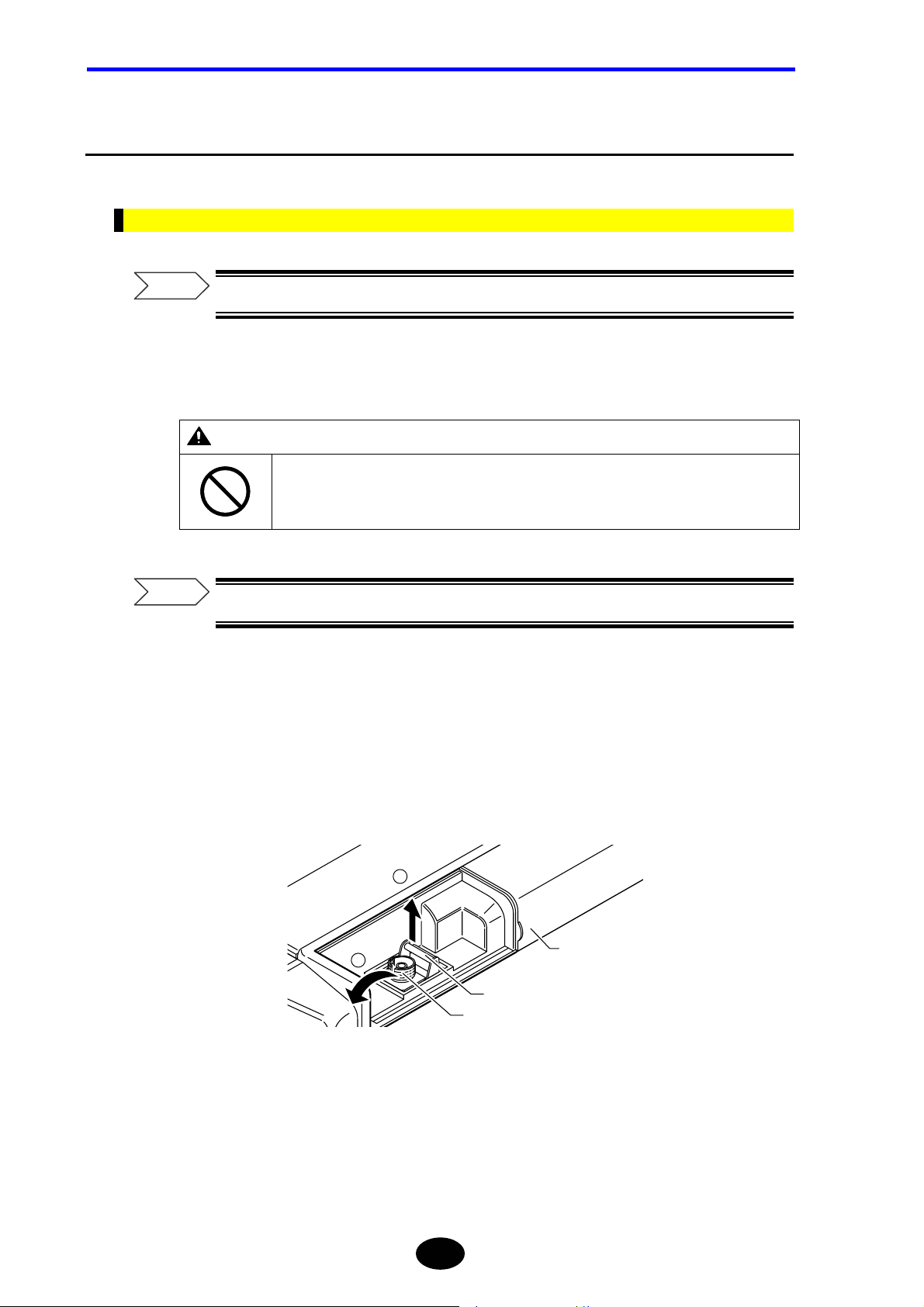
2. Slide the optical connector cover on the top of the instrument to open it.
3. Push the optical adapter’s lock lever inward to unlock the adapter.
4. Lift the adapter to pull it out.
2
1
Lock lever
Front shell
Cover of
optical fiber
cable connector
1-16
Page 44

Attaching a New Optical Adapter
Chapter 1 BEFORE USING THE INSTRUMENT
Refer
Refer to the Cautions given on page 1-18.
1. Make sure that the power to the instrument is turned OFF.
WARNING
Do not replace the optical adapter while the power to the instrument is ON.
Should the laser emit and enter the eyes, they may be seriously damaged or loss of
eyesight may result.
Refer
For the method of turning OFF the power , refer to page 3-107.
2. Slide the optical connector cover on the top of the instrument to open it.
3. Insert the new optical adapter straight into the rear shell.
4. Push the optical adapter’s lock lever outward to lock the adapter.
1-17
Page 45

Chapter 1 BEFORE USING THE INSTRUMENT
CAUTION
• Take care not to damage the end of the optical fiberl.
If the end of the optical fiber is damaged, correct measurement may no longer be
possible or the optical fiber to be measured may also be damaged.
• When removing/inserting the optical adapter, it must be removed/inserted slowly.
Shaking it sideways or removing/inserting by force may not only damage the optical
adapter, but also damage the ferrule on the optical connector.
1-18
Page 46

Chapter 1 BEFORE USING THE INSTRUMENT
1.7 Replacing the Batter y Pack
This section explains how to replace the battery pack with a new one.
Removing the Battery Pack
1. Make sure that the power to the instrument is turned OFF.
WARNING
Do not replace the battery pack while the power to the instrument is ON.
Failure to observe this may result in electric shock or breakdown.
Refer
For the method of turning OFF the power , refer to page 3-107.
2. Open the battery pack protecting rubber.
1-19
Page 47
Chapter 1 BEFORE USING THE INSTRUMENT
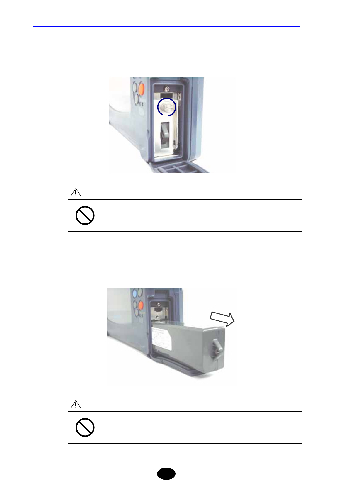
3. Remove the battery pack bracket.
Loosen the screw shown below counter-clockwise to remove the bracket.
CAUTION
When removing the bracket, make sure that the right side of the instrument is not facing
the floor.
Doing so may cause the battery pack to drop, resulting in damage.
4. Remove the battery pack.
CAUTION
Do not touch the electrodes on the removed battery pack.
Doing so may result in breakdown.
1-20
Page 48
Attaching a New Battery Pack
This section explains how to attach a new battery pack. It is assumed that the battery pack
bracket has been removed.
1. Make sure that the power to the instrument is turned OFF.
WARNING
Do not replace the battery pack while the power to the instrument is ON.
Failure to observe this may result in electric shock or breakdown.
Chapter 1 BEFORE USING THE INSTRUMENT
Refer
For the method of turning OFF the power , refer to page 3-107.
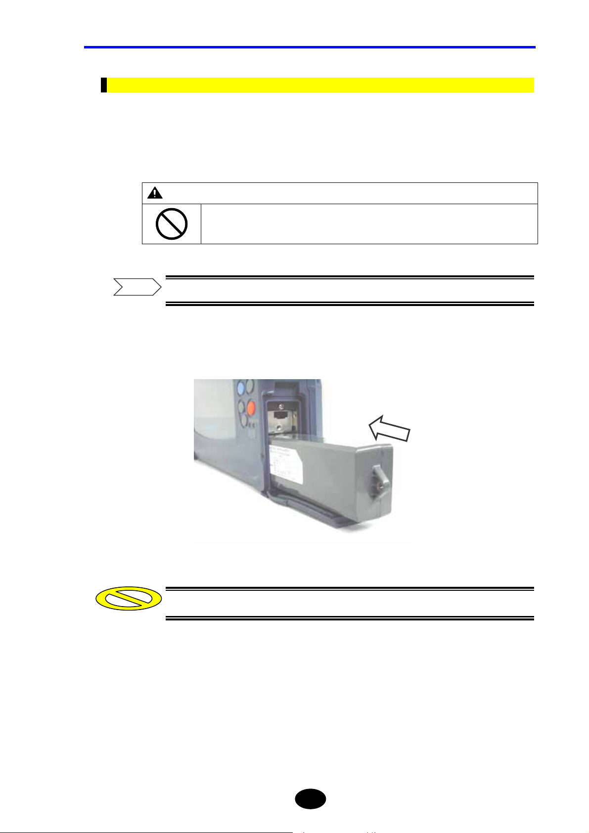
2. Insert a new battery pack into the instrument.
Caution
Make sure that the battery pack is inserted in the correct direction.
1-21
Page 49

Chapter 1 BEFORE USING THE INSTRUMENT
3. Attach the battery pack bracket.
Tighten the screw shown below clockwise to secure the bracket.
Caution
Make sure that the screw is tightened firmly.
4. Close the battery pack protecting rubber.
CAUTION
Make sure that the battery pack protecting rubber is closed firmly.
Failure to observe this may result in breakdown.
1-22
Page 50

Chapter 1 BEFORE USING THE INSTRUMENT
1.8 Charging the Battery Pack
This section explains how to charge the battery pack.
When there is insufficient power in the battery pack, charge it as explained below.
Caution
Charging of the battery pack must be performed at temperatures of 5°C to 35°C.
Charging outside this temperature range may not only deteriorate the battery
pack’s performance or shorten its life, but in the worst case may also prevent start
of charging. The CHARGE LED blinks if charging is not yet started.
The remaining power in the battery pack can be seen on the power indicato r
located in the lower right corner of the screen.
Fully charged Insufficient remaining power
The following message appears when there is insuff icient power in the battery
pack.
Low battery.
Please use AC adapter,
or replace the charged battery.
Push any key.
Take the required actions according to the above message. If the required actions
are not taken within a few minutes following the appearance of the above message,
the following message will appear and the power will be turned OFF automatically.
When the battery pack is heated, the instrument prevents to cha rg e the battery. If
the battery pack is heated. Please remove the battery pack. After the temperature
become cool to room temperature and insert battery pack.
Low battery.
OTDR will shutdown in 10 sec.
1-23
Page 51

Chapter 1 BEFORE USING THE INSTRUMENT
Refer
For the method of removing the battery pack, refer to page1-19.
1. Make sure that the power to the instrument is turned OFF.
Refer
For the method of turning OFF the power , refer to page 3-107.
2. With the battery pack installed in the instrument, connect the AC adapter to the
instrument.
Refer
•For the method of attaching the battery pack, refer to page 1-21.
•For the method of connecting the AC adapter, refer to page 3-4.
3. Insert the AC adapter’s power plug into an AC power outlet.
Charging of the battery pack will start.
CAUTION
Do not insert the AC adapter’s power plug into an AC power outlet if the power to the
instrument is ON.
TIP
The CHARGE LED will be lit steadily while the battery pack is charged, and will go
out when charging is complete.
Failure to observe this may result in breakdown.
1-24
Page 52

Chapter 1 BEFORE USING THE INSTRUMENT
1.9 Replacing the Backup Battery
This section explains how to replace the backup battery with a new one.
The backup battery must be replaced with a new one periodically, since it may cause
sudden malfunctions due to its battery life even though the instrument is working properly.
The backup battery must be replaced approximately every five years.
Caution
•When the backup battery is replaced, the date and time will be initialized.
•The battery model “CR2032” must be used.
1. Make sure that the power to the instrument is turned OFF.
WARNING
Do not replace the backup battery while the power to the instrument is ON.
Failure to observe this may result in electric shock or breakdown.
Refer
For the method of turning OFF the power , refer to page 3-107.
2. Remove the optical module cover and then remove the optical module.
Refer
For the method of removing the optical module and its cover, refer to page 1-12.
1-25
Page 53

Chapter 1 BEFORE USING THE INSTRUMENT
3. Remove the battery.
3-1. Slide the battery as shown below.
3-2. Pull up the battery
Caution
When removing the backup battery, take care not to short-circuit the instrument.
4. Insert a new battery.
Caution
Make sure that the battery is inserted in the correct direction. The printing board
side is minus.
1-26
Page 54

Chapter 1 BEFORE USING THE INSTRUMENT
5. Attach the optical module and then attach its cover.
Refer
For the method of attaching the optical module and its cover, refer to page 1-12.
CAUTION
The instrument uses a lithium battery for memory backup.
So, disposal of the instrument must be carried out according to the laws and regulations of
the country and local authorities.
1-27
Page 55
Chapter 1 BEFORE USING THE INSTRUMENT
1.10 Names of Instrument Parts
This section explains the name and function of each part of the instrument (front, rear, top
and right side panels). It also explains standard accessories and options.
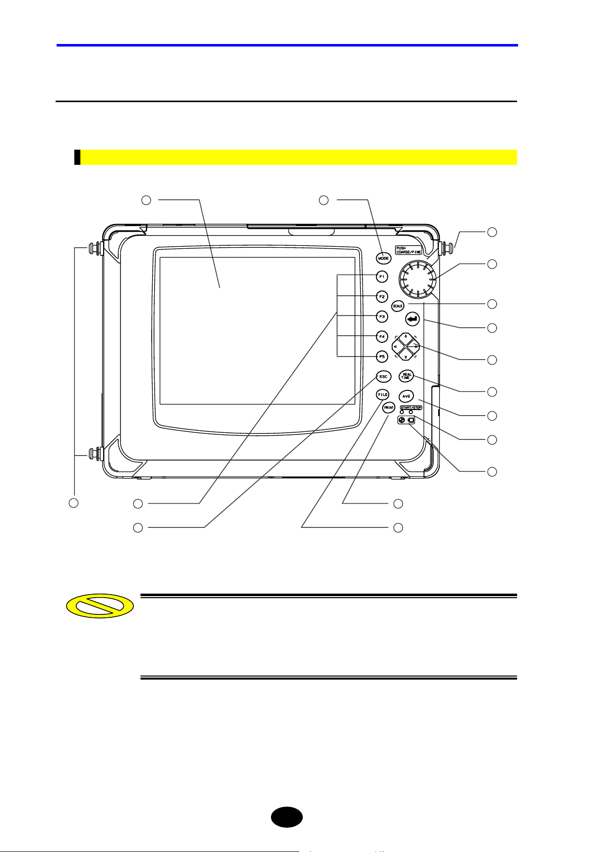
Front View
1
2
13
3
4
5
6
7
8
14
15
13
12
9
1011
Caution
The instrument uses a color LCD (hereafter called LCD). A filter plate is attached to
the front surface of the LCD for protection. However, if the filter plate is exposed to
strong impact, it may crack or the LCD itself may be damaged, so speci al care
must be taken when handling it.
1-28
Page 56

Chapter 1 BEFORE USING THE INSTRUMENT
No. Name Description
1
LCD 8.4-inch color TFT (640 x 480 dots). Measured trace, measurement
conditions and measured values are displayed.
2
MODE key Used to switch the operation mode.
3
Rotary knob Used to move the distance cursor or increase/decrease entered values.
Holding down the key will allow you to move the distance cursor at
different speeds.
4
SCALE key Used to enlarge/reduce the trace size or shift the trace.
5
ENTER key Used to confirm entered values etc.
6
Arrow key Used to move the trace, enlarge/reduce the trace size, or change
entered values.
7
REAL TIME key Starts/stops real-time measurement.
8
AVERAGE key Starts/stops average measurement.
9
PRINT key Prints out the information displayed on the screen.
10
FILE key Used for file operation (saving, deleting, recalling).
11
ESC key Used to cancel the operation or restore the previous screen contents.
12
Function keys Performs the function inscribed on each key.
13
Shoulder belt fixture Used to attach a shoulder belt to the instrument.
14
CHARGE LED Lit while the battery pack is charged.
When the battery pack is full charged, the LED is off.
15
POWER LED Lit while the power to the instrument is ON.
Conventions Used in This Manual
In this manual, each key is expressed as follows.
Example
It blinks if the battery pack has not been charged or if it is in critical
condition.
When the instrument is running on the battery pack, this LED turns from
green to red when there is insufficient power in the battery pack.
[key name]
[ENTER]
1-29
Page 57

Chapter 1 BEFORE USING THE INSTRUMENT
Rear View
1
2
3
4
5
6
Caution
No. Name Description
1
Optical adapter Used to connect the optical fiber to be measured.
2
Optical adapter cover Used to protect the optical adapter when the fiber to be measured is not
connected.
3
Sub module cover Used to protect the sub module port when no sub module is connected.
4
Sub module port Used to connect a sub module.
5
Expansion unit port Used to connect an expansion unit.
6
Stand Used to support the instrument when it is placed on a desk etc.
Class 1M laser invisible radiation when optical adapter cover open.
Do not view directly with optical instruments.
*1: When measuring or Light source function ON
CLASS 1M INVISIBLE LASER RADIATION WHEN OPEN
DO NOT VIEW DIRECTLY WITH OPTICAL INSTRUMENTS
CATION
*1
1-30
Page 58

Chapter 1 BEFORE USING THE INSTRUMENT
WARNING
When no optical fiber is connected, make sure that the optical adapter cover is closed.
Laser beams are invisible to the naked eye, but if they enter the eyes, they may cause
impaired eyesight.
CAUTION
When carrying the instrument, do not carry it by the stand.
Doing so may damage the instrument.
1-31
Page 59
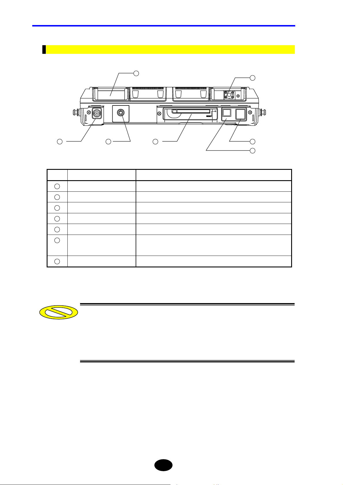
Chapter 1 BEFORE USING THE INSTRUMENT
Top View
1
2
3
4
5
6
7
No. Name Description
1
Sub module port Used to connect an optional visible light source or optical power meter.
2
Optical adapter Used to connect the optical fiber to be measured.
3
DC power connector Used to connect the AC adapter.
4
Power switch Used to turn ON/OFF the power to the instrument.
5
PCMCIA slot Used to insert an optional IC card etc.
6
USB connector (host side)
Used to connect FDD or memory.
2 ports
7
USB connector (function side) Used to connect a personal computer.
Caution
•Two USB ports (host side) are available, but do not connect a storage medium or
printer to both ports.
•Now, sub module s a re no t available. It will be developed.
•It does not support USB connector (function side) yet.
1-32
Page 60

Right Side View
Chapter 1 BEFORE USING THE INSTRUMENT
1
2
No. Name Description
1
Optical module cover Used to protect the optical module
2
Battery pack section Used to accommodate a battery pack.
1-33
Page 61

Chapter 1 BEFORE USING THE INSTRUMENT
Accessories
This section explains the accessories supplied with the instrument.
Battery pack Shoulder belt User’s Manual
1-34
Page 62
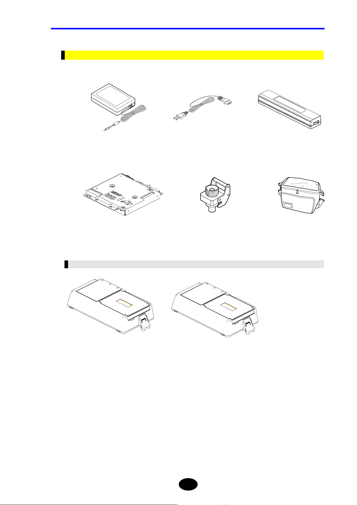
Chapter 1 BEFORE USING THE INSTRUMENT
Options
The section explains the options that can be purchased individually.
AC adapter AC power cord Battery pack
Optical module Universal adapter AQ9441 (*) Soft carrying case
Expansion Unit
Printer/FDD unit Printer unit
1-35
Page 63
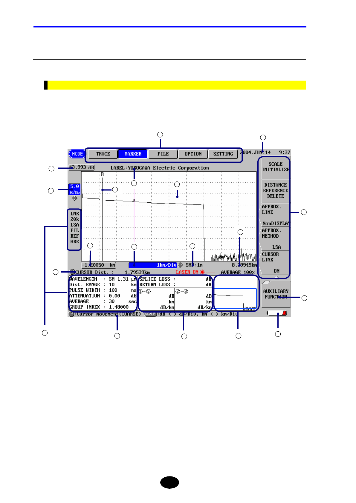
Chapter 1 BEFORE USING THE INSTRUMENT
1.11 Screen Display
This section explains screen display.
Description of Screen Display
The main screen displays the measured trace and measurement conditions.
The name and function of each part of the screen are explained below.
1
2
13
18
3
5
6
8
6
11
9
14
16
17
4
7
10
1-36
12
15
Page 64

Chapter 1 BEFORE USING THE INSTRUMENT
No. Name Description
1
MODE Highlights the currently selected mode.
2
Display start level Displays the vertical-axis display start level (above the trace display
section).
3
Vertical-axis scale Displays the value per grid along the vertical axis.
4
Measurement conditions Displays various measurement conditions.
5
Display start distance Displays the horizontal-axis display start distance (left to the trace
display section).
6
Cursor distance Displays the distance from the origin to the cursor point.
7
Guidance Displays outline of the operation.
8
Horizontal-axis scale Displays the value per grid along the horizontal axis.
9
SMP Displays the sampling resolution.
10
Calculated values Displays the calculation results obtained from the measurement data.
11
Display end distance Displays the horizontal-axis display end distance (right to the trace
display section).
12
Overall trace Displays a measured trace for the entire measured range in simplified
format. The part displayed in the main screen will be enclosed by a
frame.
13
Label Displays the entered label.
14
Date Displays the current date and time.
15
Power Displays the currently used power.
Battery mark: The instrument is running on the battery pack.
== AC ==: The instrument is running on AC power.
16
Function keys Displays the functions of the current function keys.
17
Hierarchy level Displays the hierarchy level of the operation.
The larger the tag count, the lower the hierarchy level.
18
Distance origin marker Displays the position of the distance origin.
1-37
Page 65

Chapter 1 BEFORE USING THE INSTRUMENT
Display of Measurement Conditions
Name Description
LNK Displayed when the cursor link function is currently enabled.
20k Displays the currently selected data size.
5k: 5k mode
20k: 20k mode
60k: 60k mode
LSA Displays the currently selected approximate method.
LSA: Least squares approximate
TPA: Two point approximate
FIL Displayed when the filter function is currently enabled.
REF Displayed when the distance origin marker is currently set.
HRE Displays the currently selected average method.
HRE: High return loss average
NOM: Normal average
HSP: High speed average
WAVELENGTH Displays the wavelength to be used for measurement.
Dist. RANGE Displays the distance range to be used for measurement.
PULSE WIDTH Displays the width of light pulse to be used for measurement.
ATTENUATION Displays the value set to restrict increase of the light to be measured.
AVERAGE Displays the currently selected average time or average interval.
GROUP INDEX Displays the currently selected group index.
1-38
Page 66

Chapter 1 BEFORE USING THE INSTRUMENT
Function Keys and Hierarchy Level Display
When [MODE] is pressed, the function menu for currently selected mode will be displayed.
The function keys are displayed in one of the three shapes, for each of which execution
format has been set.
Execution format for each shape is explained below.
Shape Description
When a function key of this shape is pressed, a function window
(lower-hierarchy window) relating to the function will appear.
The number of tags indicating the hierarchy level is also increased by
one. To return to the previous hierarchy level, press [ESC]
When a function key of this shape is pressed, a window allowing you to
change the currently set values or setting conditions will appear.
When a function key of this shape is pressed, the function indicated on
the key will be executed.
* 1
Higher
hierarchy
level
[ESC]
[ESC]
[ESC]
* 1
Lower
hierarchy
level
1-39
Page 67

Chapter 1 BEFORE USING THE INSTRUMENT
Meaning of Each Part of the Trace
Near
end
Splice loss
Reflection
Far end
Near end
Connection point between the instrument and optical fiber and its surrounding area
Far end
The end of an optical fiber cable and its surrounding area
If the end of the optical fiber cable cannot be detected due to noise, “far end” indicates
the cross point of the noise and optical fiber and its surrounding area.
Splice loss
Explained on the next page.
Reflection
Explained on the next page.
1-40
Page 68

Chapter 1 BEFORE USING THE INSTRUMENT
Splice Loss
Splice loss occurs at areas where the optical fiber cable is fusion spliced.
≈
Spliced area
≈
Refer
For details on approximate straight line, refer to pages 3-80 and 3-84.
Splice loss
Approximate
straight line
Reflection
Reflection occurs at areas where the optical fiber cable is connected by a connector or
areas where the optical fiber is cut off.
Reflection level is often expressed by return loss.
≈
Refer
For detail on return loss, refer to page 10-14.
Cut-off area
≈
1-41
Page 69

Chapter 1 BEFORE USING THE INSTRUMENT
1.12 Notes Before Performing Measurement
This section explains points to note when measuring a communication system. The
following points must be observed when performing measurement.
When Using AQ7261 / AQ7264 / AQ7265
These modules perform measurement by using the same wavelength as that used for
communications. Thus, if the optical fiber to be measured contains communication light,
communications will be affected. Furthermore, measurement cannot be performed
correctly by this instrument. So, the measurement environment (presence/absence of
communication light) must be taken sufficiently into account when using these modules.
For the wavelength used by the modules, refer to “Chapter 9 Specifications”.
The AQ7260 main frame can use AQ7265 module at the software version 2.00 or later.
Software version before 2.0 does not operate AQ7265 module.
CAUTION
Caution
Refer
Special care must be taken when using these modules since devices connected to the system
to be
measured may be damaged depending on total power of the light.
• Special care must be taken not to allow communication failure. Should
communication failure occur by mistake by the user, YOKOGAWA will not accept
responsibility arising from that communication failure.
• The AQ7260 main frame can use AQ7265 module at the software version 2.00 or
later.
• Procedure of software upgrade, refer to page 10-2.
• Procedure of checking software version, refer to p age 10-4.
Furthermore, take care not to allow any external light to enter the instrument.
CAUTION
Entry of external light may result in damage to the instrument.
1-42
Page 70

Chapter 2
BEFORE STARTING MEASUREMENT
2.1 Changing System Settings....................................................................................... 2-2
Page 71

Chapter 2 CHANGING SYSTEM SETTINGS
2.1 Changing System Settings
This chapter explains how to change the following system settings.
• Changing the Display Language
• Changing the Trace Type
• Changing the Cursor Type
• Changing the Grid Setting
• Changing the Second Cursor Setting
• Changing the Trace Form Setting
• Changing the Distance Unit
• Changing the Distance Reference Mark Type
• Changing the Number of dB Display Digits
• Changing the Display Color
• Changing the Date/Time
• Changing the Lockout Setting
• Changing the Alarm Sound Setting
• Changing the Power Save Setting
• Changing the LCD Brightness
• Changing the Print Type
• Changing the Print Color
2-2
Page 72

Displaying the Setting Change Window
This section explains how to display the window by which system settings can be
changed.
1. Make sure there is no measurement currently in progress.
Chapter 2 CHANGING SYSTEM SETTINGS
Caution
If measurement is in progress, it is not possible to change system parameter
settings.
Press [MODE] to locate the cursor to “SETTING”.
2.
A window allowing you to change system settings will appear.
2-3
Page 73

Chapter 2 CHANGING SYSTEM SETTINGS
Changing Settings
This section explains how to change the setting for each parameter.
TIP
The system settings are retained in the internal memory even if the instrument is
turned OFF. So, when the instrument is turned ON, the system settings in effect just
before the instrument was turned OFF last time will be restored.
Changing the Display Language
The display language can be changed as explained below.
♦ Example: “ENGLISH” → “日本語”
1. Locate the cursor to “LANGUAGE” by using the rotary knob or the arrow key.
TIP
The cursor is already at “LANGUAGE” when the setting change windo w appears.
2. Press [ENTER].
A selection window will appear.
TIP
Selectable
languages
日本語
* ENGLISH Displays characters in English.
Displays characters in Japanese.
*: Indicates the default setting.
2-4
Page 74

Chapter 2 CHANGING SYSTEM SETTINGS
3. Locate the cursor to “日本語” by using the rotary knob or [S] / [T].
4. Press [ENTER] to register the change made to the language setting.
Caution
The change will not be registered if [ESC] is pressed instead of [ENTER].
2-5
Page 75
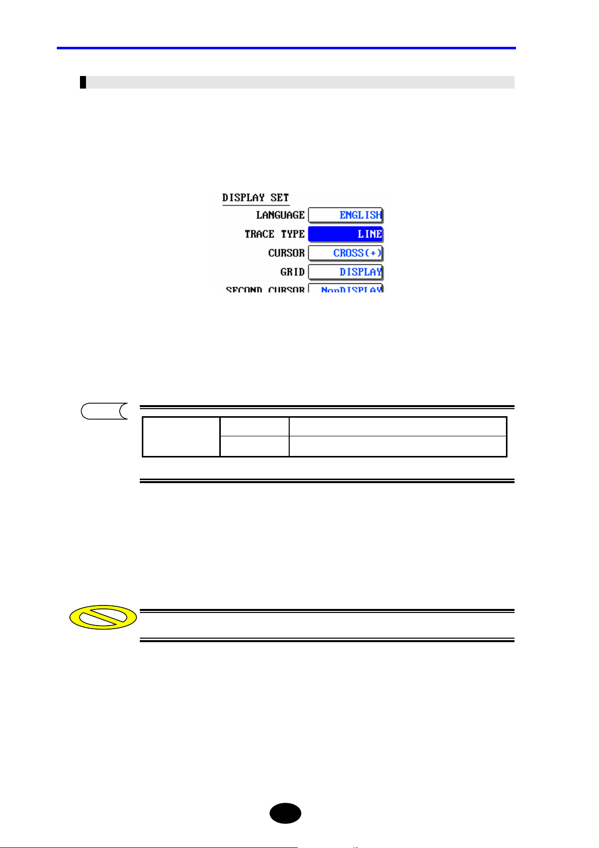
Chapter 2 CHANGING SYSTEM SETTINGS
Changing the Trace Type
The trace type can be changed as explained below.
♦ Example: “LINE” → “DOT”
1. Locate the cursor to “TRACE TYPE” by using the rotary knob or the arrow key.
Press [ENTER].
2.
A selection window will appear.
TIP
Selectable
trace types
*LINE Displays the trace in line form.
DOT Displays the trace in dot form.
*: Indicates the default setting.
3. Locate the cursor to “DOT” by using the rotary knob or [S] / [T].
4. Press [ENTER] to register the change made to the trace type.
Caution
The change will not be registered if [ESC] is pressed instead of [ENTER].
2-6
Page 76

Chapter 2 CHANGING SYSTEM SETTINGS
TIP
When “LINE” is selected
When “DOT” is selected
2-7
Page 77
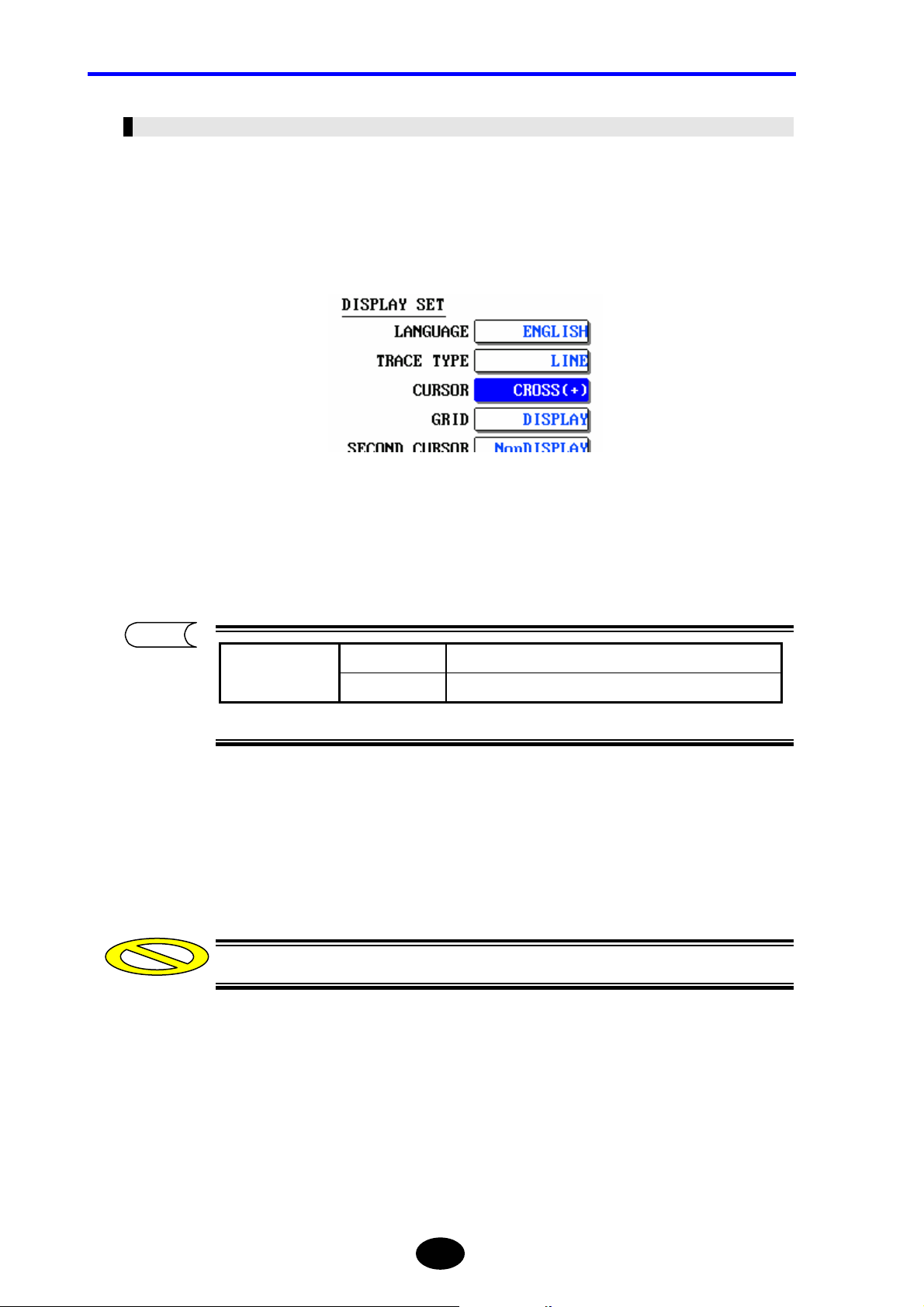
Chapter 2 CHANGING SYSTEM SETTINGS
Changing the Cursor Type
The cursor type can be changed as explained below.
♦ Example: “CROSS(+)” → “LINE( | )”
1. Locate the cursor to “CURSOR” by using the rotary knob or the arrow key.
Press [ENTER].
2.
A selection window will appear.
TIP
Selectable
cursor types
*CROSS(+) Displays the cursor by a cross (+).
LINE( | ) Displays the cursor by a line ( | ).
*: Indicates the default setting.
3. Locate the cursor to “LINE( | )” by using the rotary knob or [S] / [T].
4. Press [ENTER] to register the change made to the cursor type.
Caution
The change will not be registered if [ESC] is pressed instead of [ENTER].
2-8
Page 78
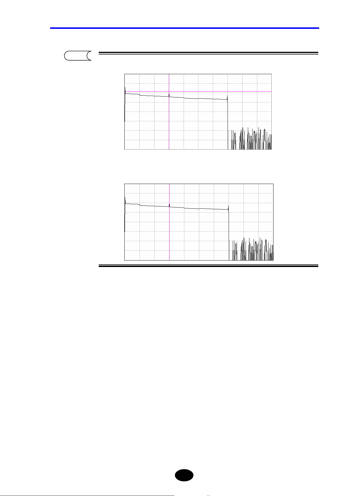
Chapter 2 CHANGING SYSTEM SETTINGS
TIP
When “CROSS(+)” is selected
When “LINE( | )” is selected
2-9
Page 79
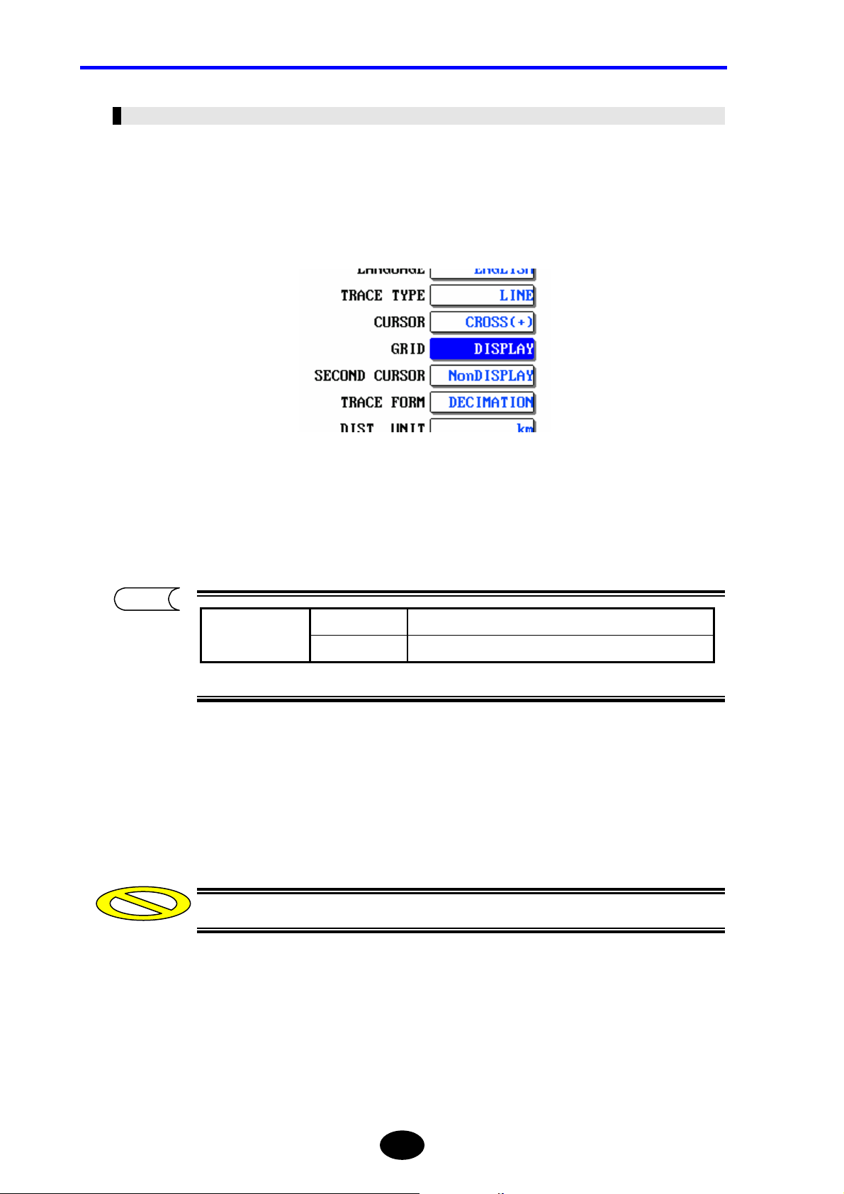
Chapter 2 CHANGING SYSTEM SETTINGS
Changing the Grid Setting
The grid setting can be changed as explained below.
♦ Example: “DISPLAY” → “NonDISPLAY”
1. Locate the cursor to “GRID” by using the rotary knob or the arrow key.
Press [ENTER].
2.
A selection window will appear.
TIP
Selectable
grid settings
NonDISPLAY Hides the grid.
*DISPLAY Shows the grid.
*: Indicates the default setting.
3. Locate the cursor to “NonDISPLAY” by using the rotary knob or [S] / [T].
4. Press [ENTER] to register the change made to the grid setting.
Caution
The change will not be registered if [ESC] is pressed instead of [ENTER].
2-10
Page 80

Chapter 2 CHANGING SYSTEM SETTINGS
TIP
When “DISPLAY” is select
When “NonDISPLAY” is selected
ed
2-11
Page 81
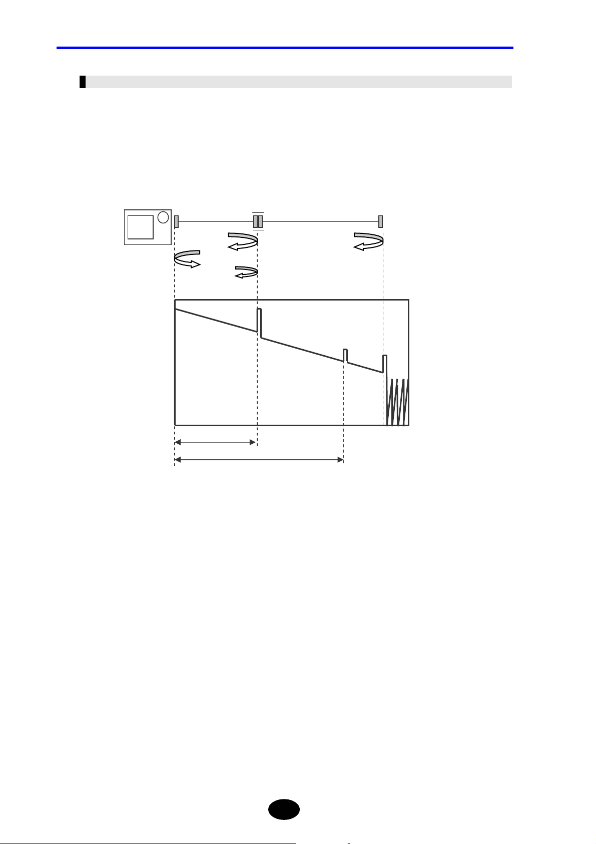
Chapter 2 CHANGING SYSTEM SETTINGS
Changing the Second Cursor Setting
Before explaining how to change the setting, an explanation is given below about the
second cursor.
The second cursor is used to check for the secondary reflection.
The secondary reflection makes an event look as if it were present in places where it is
actually not.
I
1
2
3
II
1
4
III
Distance L
Distance 2L
Assuming that excessive reflection occurs at point II
Mechanism of generation of secondary reflection
A pulsed ray that is output at point I advances toward point II.
↓
The ray (1) reflecting on the spliced surface at point II reflects again on the spliced
surface at point I and advances toward point II (2).
The instrument acquires 1 as data.
3
4
↓
Due to the ray 2, a reflection ray (3) is generated again on the spliced surface at
point II.
The instrument acquires 3 as data.
Since all the reflection rays (1, 3, 4) are measured by the instrument, 3 is also acquired
as data in the same way as those that are actually generated, and is displayed. As a
result, the secondary reflection makes an event look as if it were present in places where it
is actually not.
2-12
Page 82

Chapter 2 CHANGING SYSTEM SETTINGS
The second cursor can be changed as explained below.
♦ Example: “NonDISPLAY” → “DISPLAY”
1. Locate the cursor to “SECOND CURSOR” by using the rotary knob or the arrow
key.
Press [ENTER].
2.
A selection window will appear.
TIP
Selectable second
cursor settings
*NonDISPLAY Hides the second cursor.
DISPLAY Shows the second cursor.
*: Indicates the default setting.
3. Locate the cursor to “DISPLAY” by using the rotary knob or [S] / [T].
4. Press [ENTER] to register the change made to the second cursor.
Caution
The change will not be registered if [ESC] is pressed instead of [ENTER].
2-13
Page 83

Chapter 2 CHANGING SYSTEM SETTINGS
TIP
When “NonDISPLAY” is selected
When “DISPLAY” is selected
secondary reflection
second cursor
The second cursor is displayed at a position twice as far as the distance from the
zero point as the cursor.
2-14
Page 84

Chapter 2 CHANGING SYSTEM SETTINGS
Changing the Trace Form Setting
Before explaining how to change the setting, an explanation is given below about trace
form.
This instrument can acquire data of maximum 60,000 points. However, since the number
of dots on the LCD is limited, it is not possible to display all the acquired data at the same
time. Therefore, the instrument employs methods to display only the selected data. The
following four display methods are available.
• DECIMATION
• MAXIMUM
• MEAN
• ENVELOPE
Before explaining each display method, an explanation is given below about the data
display section of the instrument.
The instrument uses 500 dots (horizontal direction) on the LCD to display the acquired
data.
So, the data quantity per dot can be calculated as follows.
Data quantity per dot = Acquired data quantity / 500
If the data size is 60,000 points, the data quantity assigned per dot will be 120 points.
Refer
The procedure to choose and display data (120 points) assigned for each dot is shown
below for each display method.
For the method of changing the data size, refer to page 3-28.
DECIMATION
The data to be displayed on each dot is the first data of those assigned for each dot.
1st dot: Displays the first data.
2nd dot: Displays the 121st data.
y
y
y
499th dot: Displays the 59761st data.
500th dot: Displays the 59881st data.
2-15
Page 85

Chapter 2 CHANGING SYSTEM SETTINGS
MAXIMUM
The data to be displayed on each dot is the maximum reflection level value among the
data assigned to each dot.
1st dot: Display the maximum value among the 1st to 120th data.
2nd dot: Display the maximum value among the 121st to 240th data.
y
y
y
499th dot: Display the maximum value among the 59761st to 59880th data.
500th dot: Display the maximum value among the 59881st to 60000th data.
MEAN
The data to be displayed on each dot is the mean value of all the data assigned to each
dot.
1st dot: Displays the mean value among the 1st to 120th data.
2nd dot: Displays the mean value among the 121st to 240th data.
y
y
y
499th dot: Displays the mean value among the 59761st to 59880th data.
500th dot: Displays the mean value among the 59881st to 60000th data.
ENVELOPE
The data to be displayed on each dot is the maximum and minimum reflection level values
among the data assigned for each dot by turns. The maximum and minimum values are
linked by a straight line.
1st dot: Displays the maximum values among the 1st to 120th data.
2nd dot: Displays the minimum values among the 121st to 240th data.
y
y
y
499th dot: Displays the maximum values among the 59761st to 59880th data.
500th dot: Displays the minimum values among the 59881st to 60000th data.
2-16
Page 86

Chapter 2 CHANGING SYSTEM SETTINGS
The trace form can be changed as explained below.
♦ Example: “DECIMATION” → “MAXIMUM”
1. Locate the cursor to “TRACE FORM” by using the rotary knob or the arrow key.
Press [ENTER].
2.
A selection window will appear.
TIP
*DECIMATION
Selectable
race forms
*: Indicates the default setting.
MEAN
MAXIMUM
ENVELOPE
3. Locate the cursor to “MAXIMUM” by using the rotary knob or [S] / [T].
4. Press [ENTER] to register the change made to the trace form.
Caution
The change will not be registered if [ESC] is pressed instead of [ENTER].
2-17
Page 87

Chapter 2 CHANGING SYSTEM SETTINGS
Changing the Distance Unit
The distance unit can be changed as explained below.
♦ Example: “km” → “mile”
1. Locate the cursor to “DIST. UNIT” by using the rotary knob or the arrow key.
Press [ENTER].
2.
A selection window will appear.
TIP
Selectable
distance units
*: Indicates the default setting.
*km
mile
kf
3. Locate the cursor to “mile” by using the rotary knob or [S] / [T].
4. Press [ENTER] to register the change made to the distance unit.
Caution
The change will not be registered if [ESC] is pressed instead of [ENTER].
2-18
Page 88

Chapter 2 CHANGING SYSTEM SETTINGS
Changing the Distance Reference Mark Type
The distance reference mark type can be changed as explained below.
♦ Example: “LINE” → “ARROW”
Refer
For the method of changing the distance reference, refer to page 7-27.
1. Locate the cursor to “DIST. REF. MARK” by using the rotary knob or the arrow
key.
Press [ENTER].
2.
A selection window will appear.
TIP
Selectable
mark types
*: Indicates the default setting.
*LINE
ARROW
3. Locate the cursor to “ARROW” by using the rotary knob or [S] / [T].
4. Press [ENTER] to register the change made to the distance reference mark type.
Caution
The change will not be registered if [ESC] is pressed instead of [ENTER].
2-19
Page 89

Chapter 2 CHANGING SYSTEM SETTINGS
TIP
When “LINE” is selected
When “ARROW” is selected
2-20
Page 90
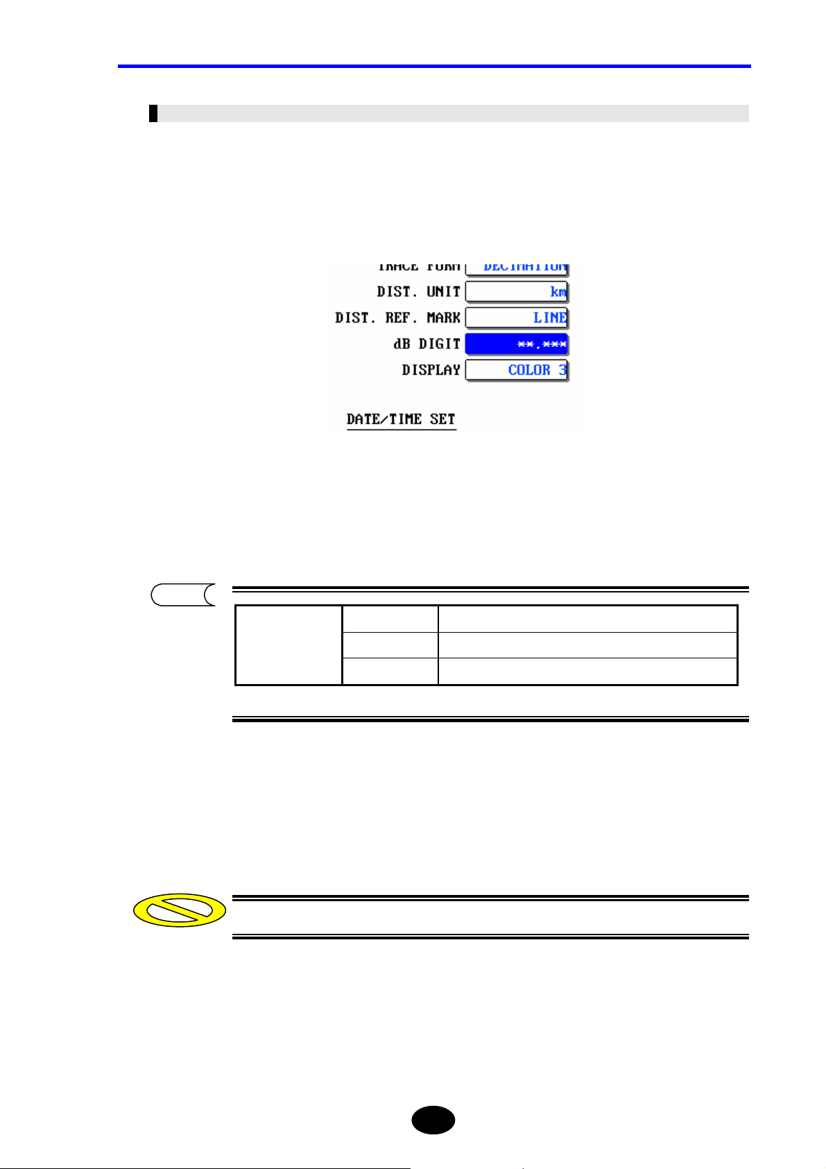
Chapter 2 CHANGING SYSTEM SETTINGS
Changing the Number of dB Display Digits
The number of dB display digits can be changed as explained below.
♦ Example: “∗∗.∗∗∗” → “∗∗.∗∗”
1. Locate the cursor to “dB DIGIT” by using the rotary knob or the arrow key.
Press [ENTER].
2.
A selection window will appear.
TIP
Displays dB with one decimal place.
∗∗.∗
Selectable
dB digits
∗∗.∗∗
*∗∗.∗∗∗
Displays dB with two decimal places.
Displays dB with three decimal places.
*: Indicates the default setting.
3. Locate the cursor to “∗∗.∗∗” by using the rotary knob or [S] / [T].
4. Press [ENTER] to register the change made to the number of dB display digits.
Caution
The change will not be registered if [ESC] is pressed instead of [ENTER].
2-21
Page 91
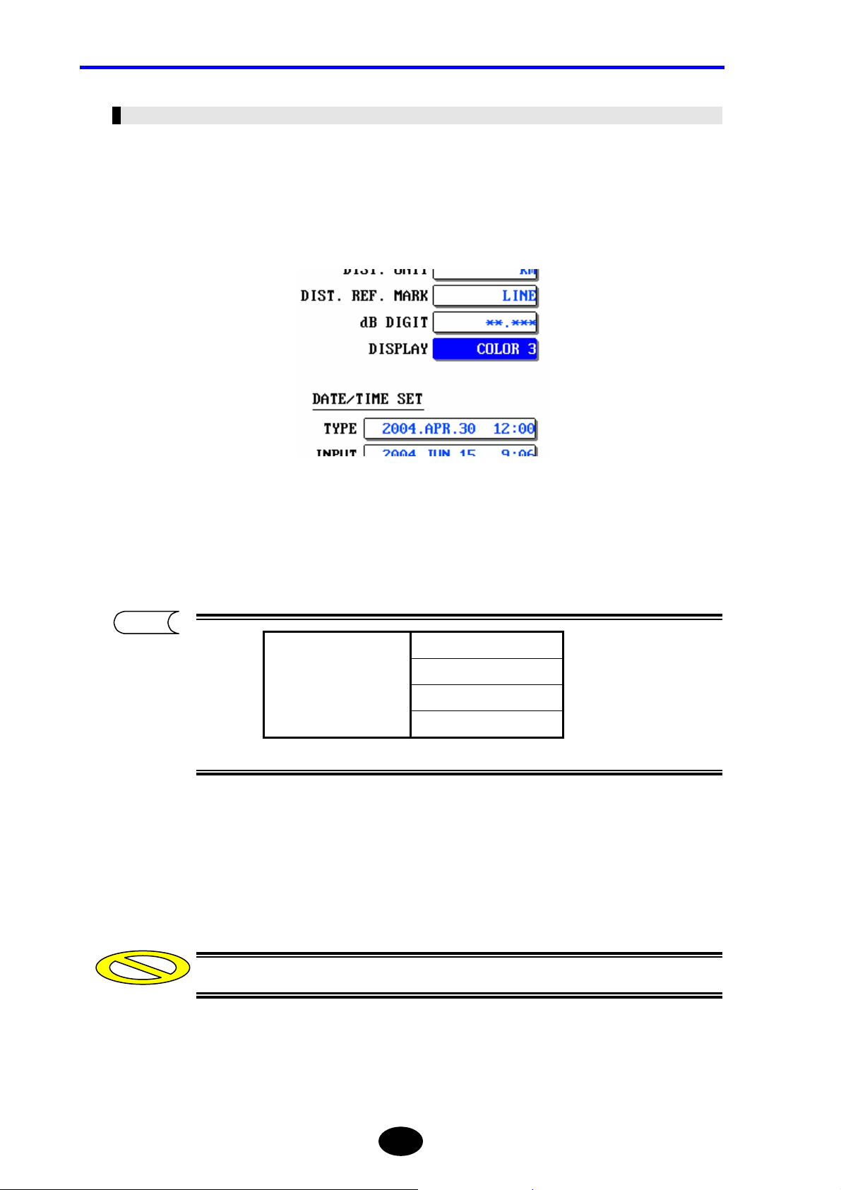
Chapter 2 CHANGING SYSTEM SETTINGS
Changing the Display Color
The display color can be changed as explained below.
♦ Example: “COLOR3” → “B&W”
1. Locate the cursor to “DISPLAY” by using the rotary knob or the arrow key.
Press [ENTER].
2.
A selection window will appear.
TIP
*COLOR1
Selectable
display colors
*: Indicates the default setting.
COLOR2
COLOR3
B&W
3. Locate the cursor to “B&W” by using the rotary knob or [S] / [T].
4. Press [ENTER] to register the change made to the display color.
Caution
The change will not be registered if [ESC] is pressed instead of [ENTER].
2-22
Page 92

Chapter 2 CHANGING SYSTEM SETTINGS
Changing the Date/Time Display Format
The date/time display format can be changed as explained below.
♦ Example: “2004.APR.30 12:00” → “2004.4.30 12:00”
1. Locate the cursor to “TYPE” by using the rotary knob or the arrow key.
Press [ENTER].
2.
A selection window will appear.
TIP
APR.30.2004 12:00 Displays the date/time in order of MONTH (alphabet), DAY
and YEAR.
4.30.2004 12:00 Displays the date/time in order of MONTH (numeric), DAY
and YEAR.
30.APR.2004 12:00 Displays the date/time in order of DAY, MONTH (alphabet)
Selectable
display
formats
The date/time displayed in the selection window is an example only to show how it
30.4.2004 12:00 Displays the date/time in order of DAY, MONTH (numeric)
*2004.APR.30 12:00 Displays the date/time in order of YEAR, MONTH (alphabet)
2004.4.30 12:00 Displays the date/time in order of YEAR, MONTH (numeric)
NonDISPLAY Hides the date/time.
and YEAR.
and YEAR.
and DAY.
and DAY.
*: Indicates the default setting.
will look, not the actual date/time.
The date/time can be changed in the [INPUT] field.
3. Locate the cursor to “2004.4.30 12:00” by using the rotary knob or [S] / [T].
2-23
Page 93

Chapter 2 CHANGING SYSTEM SETTINGS
4. Press [ENTER] to register the change made to the date/time display format.
Caution
TIP
The change will not be registered if [ESC] is pressed instead of [ENTER].
The selected display format will be reflected on the current time (displayed in the
upper right corner of the screen), and date/time for the file list.
2-24
Page 94
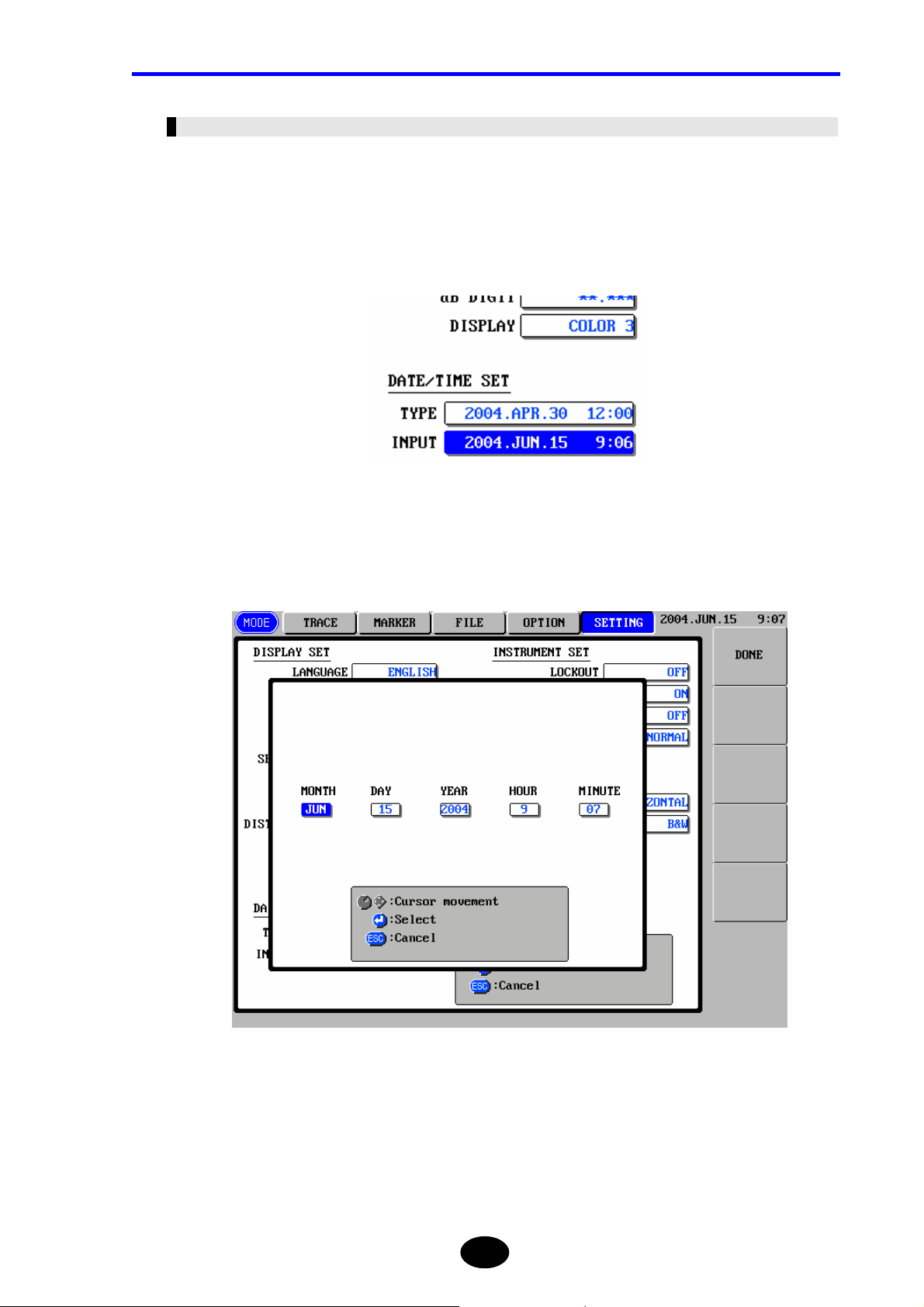
Chapter 2 CHANGING SYSTEM SETTINGS
Changing the Date/Time
The date/time can be changed as explained below.
♦ Example: “2004.JUN.15 9:06” → “2005.JUN.15 9:20”
1. Locate the cursor to “INPUT” by using the rotary knob or the arrow key.
2. Press [ENTER].
The following window will appear.
2-25
Page 95
Chapter 2 CHANGING SYSTEM SETTINGS
3. Change the year.
3-1. Locate the cursor to “YEAR” by using the rotary knob or [W] / [X].
3-2. Press [ENTER].
A selection window will appear.
3-3. Locate the cursor to “2005” by using the rotary knob or [S] / [T].
3-4. Press [ENTER] to register the change made to the year.
4. Change the minute.
4-1. Locate the cursor to “MINUTE” by using the rotary knob or [W] / [X].
4-2. Press [ENTER].
A selection window will appear.
4-3. Locate the cursor to “20” by using the rotary knob or [S] / [T].
4-4. Press [ENTER] to register the change made to the minute.
TIP
The month, day and hour can be changed in the same way as year and minute.
5. Press [F1](DONE) to register the change made to the date/time .
Caution
The change will not be registered if [ESC] is pressed instead of [ENTER].
2-26
Page 96

Chapter 2 CHANGING SYSTEM SETTINGS
Changing the Lockout Setting
The lockout function is to prevent the preset measurement conditions and system settings
being changed by other operators. If this function is enabled, the measurement conditions
and system settings cannot be changed.
The lockout setting can be changed as explained below.
♦ Example: “OFF” → “ON” (setting the lockout code to “7260”)
1. Locate the cursor to “LOCKOUT” by using the rotary knob or the arrow key.
2. Press [ENTER].
A selection window will appear.
TIP
*OFF Disables the lockout function. Selectable
lockout settings
ON Enables the lockout function.
*: Indicates the default setting.
3. Locate the cursor to “ON” by using the rotary knob or [S] / [T].
2-27
Page 97

Chapter 2 CHANGING SYSTEM SETTINGS
4. Press [ENTER].
The following window will appear.
Enter a lockout code (4-digit code) as follows. In this example, “7260” is
5.
entered.
5-1 Locate the cursor to “7” by using the rotary knob or [W] / [X].
5-2 Press [ENTER].
5-3 Locate the cursor to “2” by using the rotary knob or [W] / [X].
5-4 Press [ENTER].
5-5 Locate the cursor to “6” by using the rotary knob or [W] / [X].
5-6 Press [ENTER].
5-7 Locate the cursor to “0” by using the rotary knob or [W] / [X].
5-8 Press [ENTER].
5-9 Press the [F1](DONE) key.
Caution
The lockout code must be a 4-digit number.
2-28
Page 98

Chapter 2 CHANGING SYSTEM SETTINGS
6. Enter the same lockout code again.
Enter it according to steps 5-1 to 5-9.
Caution
y The lockout function will be enabled when the same lockout code is entered at
both steps 5 and 6.
y Do not forget the lockout code. It will be required when disabling the function.
Disabling the Lockout Function
1. Perform steps 1 and 2.
2. Select “OFF” in the selection window.
3. Enter the same lockout code.
4. Press the [F1] (DONE) key.
2-29
Page 99

Chapter 2 CHANGING SYSTEM SETTINGS
Changing the Alarm Sound Setting
If this setting is enabled (ON), the buzzer will sound when a warning message is
displayed.
The alarm sound setting can be changed as explained below.
♦ Example: “ON” → “OFF”
1. Locate the cursor to “ALARM SOUND” by using the rotary knob or the arrow
key.
Press [ENTER].
2.
A selection window will appear.
TIP
OFF Disables the buzzer. Selectable
alarm sound settings
*ON Enables the buzzer.
*: Indicates the default setting.
3. Locate the cursor to “OFF” by using the rotary knob or [S] / [T].
4. Press [ENTER] to register the change made to the alarm sound setting.
Caution
The change will not be registered if [ESC] is pressed instead of [ENTER].
2-30
Page 100
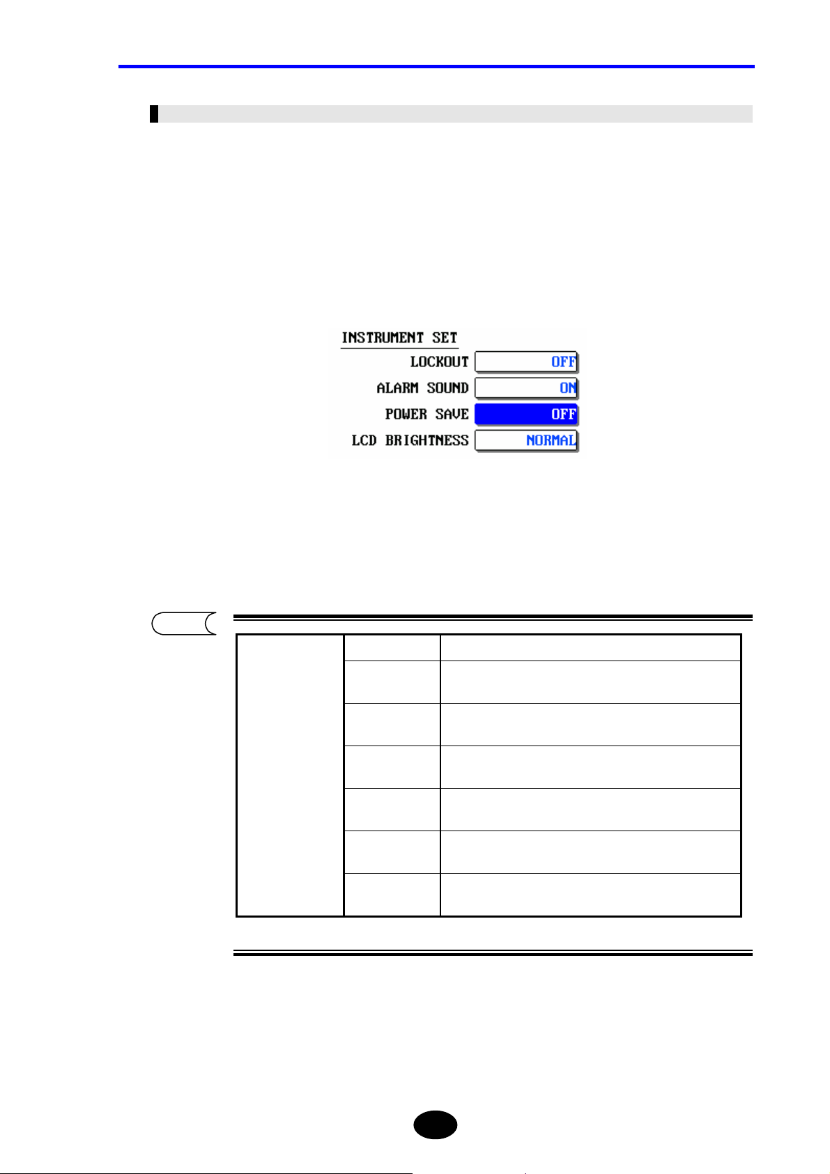
Chapter 2 CHANGING SYSTEM SETTINGS
Changing the Power Save Setting
The power save function is to save power consumption by turning OFF the LCD display’s
backlight automatically when the instrument is ON but not operated for a certain period of
time.
The power save setting can be changed as explained below.
♦ Example: “OFF” → “3min”
1. Locate the cursor to “POWER SAVE” by using the rotary knob or the arrow key.
Press [ENTER].
2.
A selection window will appear.
TIP
*OFF Disables the power save function.
30sec
Selectable
power save
settings
10min
Enables the power save function if no keys are pressed
for 30 seconds.
Enables the power save function if no keys are pressed
1min
for 1 minute.
Enables the power save function if no keys are pressed
3min
for 3 minutes.
Enables the power save function if no keys are pressed
5min
for 5 minutes.
Enables the power save function if no keys are pressed
for 10 minutes.
20min
Enables the power save function if no keys are pressed
for 20 minutes.
*: Indicates the default setting.
2-31
 Loading...