

YOKOGAWA AQ6375 Getting Started Manual

User’s
Manual
AQ6375
Optical Spectrum Analyzer
Getting Started Guide
IM AQ6375-02EN
3rd Edition

Product Registration
Thank you for purchasing YOKOGAWA products.
YOKOGAWA provides registered users with a variety of information and
services.
Please allow us to serve you best by completing the product registration
form accessible from our homepage.
http://tmi.yokogawa.com/
PIM 103-03E

iii
IM AQ6375-02EN
Foreword
Thank you for purchasing the AQ6375 Optical Spectrum Analyzer. This instrument
enables high speed measurement of the optical properties of LD and LED light sources,
optical amps, and other devices. To improve ease of use, it includes mouse-based user
operation and a brand-new zoom function.
This getting started guide describes the instrument’s functions, operating procedures,
and handling precautions, and provides other important information for use of the
instrument. For correct operation, please read this manual thoroughly before use. After
reading this manual, keep it in a convenient location for quick reference in the event a
question arises during operation. There are three manuals for the AQ6375 including this
one. Read them along with this manual.
Manual Title Manual No. Description
AQ6375 Optical
Spectrum Analyzer
User’s Manual
IM AQ6375-01EN The manual is located on the CD included
in your package (pdf format). Explains all
functions and operating procedures of the
AQ6370C except remote control and program
functions.
AQ6370C/AQ6373/
AQ6375 Optical
Spectrum Analyzer
Remote Control User’s
Manual
IM AQ6370C-17EN The manual is located on the CD included
in your package (pdf format).Explains
functions for controlling the instrument with
communication commands and program
functions.
AQ6375 Optical
Spectrum Analyzer
Getting Started Guide
IM AQ6375-02EN This manual. Explains instrument handling
precautions and basic operating procedures.
Notes
• The contents of this manual are subject to change without prior notice as a result
of improvements in the instrument’s performance and functions. Display contents
illustrated in this manual may differ slightly from what actually appears on your screen.
•
Every ef
fort has been made in the preparation of this manual to ensure the accuracy
of its contents. However, should you have any questions or find any errors, please
contact your nearest YOKOGAWA dealer.
• Copying or reproducing all or any part of the contents of this m
anual without the
permission of Yokogawa Meters & Instruments Corporation is strictly prohibited.
• A
warranty sheet is included. It cannot be reissued. After reading the sheet, keep it in
a safe location.
Trademarks
• Microsoft and Windows are trademarks or registered trademarks of Microsoft
Corporation in the United States and/or other countries.
• Adobe,
Acrobat, and PostScript are trademarks or registered trademarks of Adobe
Systems incorporated.
• The company and product names used in this manual are not
accompanied by the
trademark or registered trademark symbols (TM, )
• Other company and product names are trademarks or register
ed trademarks of their
respective companies.
Revisions
• 1st Edition: January 2011
• 2nd Edition: November 2012
• 3rd Edition: August 2013
3rd Edition : August 2013 (YMI)
All Rights Reserved, Copyright © 2011 Yokogawa Meters & Instruments Corporation

iv
IM AQ6375-02EN
Checking the Contents of the Package
After opening the package, check the following items before beginning use. If any of the
contents are incorrect, missing, or appear to be abnormal, please contact your Yokogawa
dealer or representative.
AQ6375 Main Unit
Check that the model and suffix code on the name plate on the rear of the instrument
match those of your order. When contacting the dealer from which you purchased the
instrument, please give them the instrument number.
MODEL Suffix Code Description
AQ6375 Optical Spectrum Analyzer AQ6375
Specification -10 Standard model
Power cord
1
-D UL/CSA standard power cord (part no.: A1006WD),
maximum rated voltage: 125 V
-F VDE standard power cord (part no.: A1009WD),
maximum rated voltage: 250 V
-G
AS standard power cord (part no.: A1013WD),
maximum rated voltage: 250 V
-Q
BS standard power cord (part no.: A1054WD),
maximum rated voltage: 250 V
-H
GB standard power cord (complies with the CCC)
(part no.: A1006WD), maximum rated voltage: 250 V
-M
UL/CSA standard power cord with 3P/2P converter
(part no.: A1006WD), maximum rated voltage: 125 V
Options /FC
AQ9447 (FC) connector adapter (for optical input)
/SC AQ9447 (SC) connector adapter (for optical input)
/ST AQ9447 (ST) connector adapter (for optical input)
/RFC AQ9441 (FC) universal adapter (for calibration light source
output)
/RSC AQ9441 (SC) universal adapter (for calibration light source
output)
/RST AQ9441 (ST) universal adapter (for calibration light source
output)
/B5
Built-in thermal printer
1 Make sure that the attached power cord meets the designated standards of the country and
area that you are using it in.
• No. (Instrument Number)
Please contact your nearest Yokogawa representative.
Accessories
Part Name Quantity
Power cord
1
1
User's manual (CD) 1
Getting Start Guide 1
Rubber feet 2 pieces (1 A9088ZM sheet)
Printer roll paper (with /B5 option) 1
1 Make sure that the attached power cord meets the designated standards of the country and
area that you are using it in.

v
IM AQ6375-02EN
Checking the Contents of the Package
Accessories (Sold Separately)
Part Name Model/Part Number Specifications
AQ9447 connector adapter 810804602-FCC FC type (for optical input)
810804602-SCC SC type (for optical input)
810804602-STC ST type (for optical input)
AQ9441 universal adapter 813917321-FCC FC type (for calibration light source output)
813917321-SCC SC type (for calibration light source output)
813917321-STC ST type (for calibration light source output)
Printer roll paper B9988AE Lot size is 10 rolls, 10 meters each
vi
IM AQ6375-02EN
Safety Precautions
This instrument is an IEC safety class I(provided with terminal for protective earth
grounding). The general safety precautions described herein must be observed
during all phases of operation. If the instrument is used in a manner not specified in
this manual, the protection provided by the instrument may be impaired. Yokogawa
Electric Corporation assumes no liability for the customer’s failure to comply with these
requirements.
The following symbols are used on this instrument.
Danger, Refer to the user's manual.
This symbol appears on dangerous locations on the instrument which require
special instructions for proper handling or use. The same symbol appears in the
corresponding place in the manual to identify those instructions.
Alternating current
ON(power)
OFF(power)

vii
IM AQ6375-02EN
Safety Precautions
Failure to comply with the precautions below could lead to injury or death or
damage to the instrument.
WARNING
• Use the Instrument Only for Its Intended Purpose
The optical measuring instrument is designed to measure the optical
characteristics of light sources and evaluate their performance. Do not use this
instrument for anything other than as an optical measuring instrument.
• Check the Physical Appearance
Do not use the instrument if there is a problem with its physical appearance.
• Use the Correct Power Supply
Before connecting the power cord, ensure that the source voltage matches the
rated supply voltage of the instrument and that it is within the maximum rated
voltage of the provided power cord.
• Use the Correct Power Cord and Plug
To prevent the possibility of electric shock or fire, be sure to use the power cord
supplied by YOKOGAWA. The main power plug must be plugged into an outlet
with a protective earth terminal. Do not disable this protection by using an
extension cord without protective earth grounding.
Also, do not use power cord that came with the instrument on any other device.
• Connect the Protective Grounding Terminal
Make sure to connect the protective earth to prevent electric shock before
turning ON the power. The power cord that comes with the instrument is a
three-prong type power cord. Connect the power cord to a properly grounded
three-prong outlet.
• Do not Impair the Protective Grounding
Never cut off the internal or external protective earth wire or disconnect the
wiring of the protective earth terminal. Doing so poses a potential shock hazerd.
• Do not Operate with Defective Protective Grounding or Fuse
Do not operate the instrument if the protective earth or fuse might be defective.
Make sure to check them before operation.
• Reference light source output light
The instrument has a built-in reference light source for wavelength calibration,
and infrared light is always being output from the optical output connector. Never
look into the optical output connector. Infrared light entering the eyes can cause
severe injury and loss of vision.
• Do not Operate in an Explosive Atmosphere
Do not operate the instrument in the presence of flammable liquids or vapors.
Operation in such environments constitutes a safety hazard.
• Do Not Remove the Covers or Disassemble or Alter the Instrument
Only qualified YOKOGAWA personnel may remove the covers and disassemble
or alter the instrument.
Opening the cover is dangerous, because some areas inside the instrument
have high voltages.
• Installation Location
• This instrument is designed to be used indoors. Do not install or use it
outdoors.
• Install
the instrument so that you can immediately remove the power cord if an
abnormal or dangerous condition occurs.

viii
IM AQ6375-02EN
Safety Precautions
• Laser Class 1
This instrument complies with “Class 1 laser product” defined in “IEC60825-1.
Never look at the optical output connector or the top end of the optical fiber
connected to the optical output connector while the infrared light is being output.
If the infrared light output is observed at a distance of 100mm or less from the
infrared light emitting part by means of optical method (loupe, magnifying glass,
microscope, etc.), this may cause eye injury. The infrared light cannot be seen.
However, if the infrared light enters your eye(s), this may cause eye injury and
the eyesight to be ruined excessively.
Safety Precautions for Laser Products
This instrument uses a laser light source. This instrument is a Class 1 laser product
as defined by IEC 60825-1 Safety of Laser Products-Part 1: Equipment Classification,
Requirements and User’s Guide.
CLASS 1
LASER PRODUCT
Laser Class 1 Label
If the laser output is observed at a distance of
100mm or less from the laser beam emitting
part by means of optical method (loupe,
magnifying glass, microscope, etc.), this may
cause eye unjury.
Class Laser Type Wavelength Maximum
Output Power
Diameter of
Mode Field
Numerical
Aperture
1 EL-LED 1.55µm 0.04mW 9µm 0.1
CAUTION
Operating Environment Limitations
This product is a Class A (for industrial environments) product. Operation of this
product in a residential area may cause radio interference in which case the user
will be required to correct the interference.
ix
IM AQ6375-02EN
Waste Electrical and Electronic Equipment
Waste Electrical and Electronic Equipment (WEEE), Directive 2002/96/EC
(This directive is valid only in the EU.)
This product complies with the WEEE Directive (2002/96/EC) marking
requirement.
This marking indicates that you must not discard this electrical/
electronic product in domestic household waste.
Product Category
With reference to the equipment types in the WEEE directive Annex 1, this
product is classified as a “Monitoring and Control instrumentation” product.
Do not dispose in domestic household wast
e. When disposing products in the EU,
contact your local Yokogawa Europe B. V. office.
New EU Battery Directive
New EU Battery Directive, DIRECTIVE 2006/66/EC
(This directive is valid only in the EU.)
Batteries are included in this product. This marking indicates they shall be sorted
out and collected as ordained in ANNEX II in DIRECTIVE 2006/66/EC.
Battery type
Lithium battery
You cannot replace batteries by yourself. When you need to replace batteries,
contact your local Yokogawa Europe B.V.office.

x
IM AQ6375-02EN
Symbols and Notation Used in This Manual
Safety Markings
The following markings are used in this manual.
Improper handling or use can lead to injury to the user or damage to
the instrument. This symbol appears on the instrument to indicate
that the user must refer to the user's manual for special instructions.
The same symbol appears in the corresponding place in the user's
manual to identify those instructions. In the manual, the symbol is
used in conjunction with the word “WARNING” or “CAUTION.”
WARNING
Calls attention to actions or conditions that could cause serious or
fatal injury to the user, and precautions that can be taken to prevent
such occurrences.
CAUTION
Calls attentions to actions or conditions that could cause light injury to
the user or damage to the instrument or user’s data, and precautions
that can be taken to prevent such occurrences.
Note
Calls attention to information that is important for proper operation of
the instrument.
Notations Used on Pages Describing Operating Procedures
On pages that describe the operating procedures, the following notations are used to
distinguish the procedures from their explanations.
Procedure
This subsection contains the operating procedure used to carry out
the function described in the current chapter. All procedures are
written with inexperienced users in mind; experienced users may not
need to carry out all the steps.
Explanation
This subsection describes the setup parameters and the limitations
on the procedures.
Notations Used in the Procedures
Panel Keys and Soft keys
Bold characters used in the procedural explanations indicate characters that are marked on the
panel keys or the characters of the soft keys displayed on the screen menu.
Unit
k: Denotes “1000.” Example: 100kS/s
K: Denotes “1024.” Example: 459KB (file data size)
xi
IM AQ6375-02EN
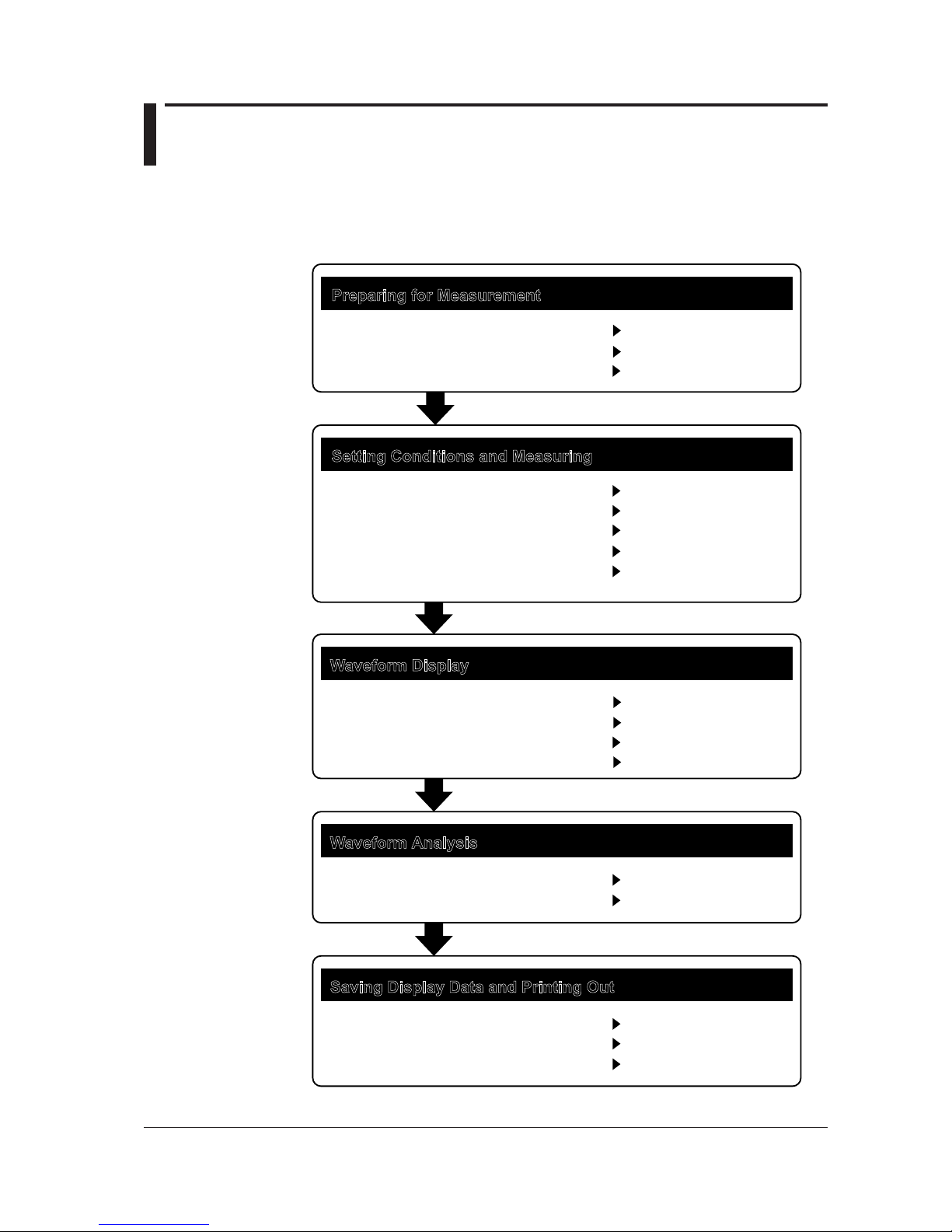
Flow of Operation
The figure below is provided to familarize the first-time user with the general flow of this
instrument operation. For a description of each item, see the relevant section or chapter
of IM AQ6375-01EN.
Preparing for Measurement
Setting Conditions and Measuring
Waveform Display
Installing the Instrument
Turning the Power ON/OFF
Wavelength Calibration
Auto Sweep Setting and Measurement
Other Settings
Waveform Display
Displaying Calculated Waveforms
Marker Display
Searching
Waveform Analysis
Waveform Analysis
GO/NO-GO Judgment
Saving Display Data and Printing Out
Storage Media
Saving Data
Internal Printer(Optional)
Section 3.1
Section 3.4
Section 3.7
Section 5.1
Section 5.2 to 5.11
Section 6.1 to 6.4
Section 6.5
Section 6.8
Section 6.12
Section 7.1 to 7.9
Section 7.12
Section 8.1
Section 8.2 to 8.8
Section 4.6
Measurement Start (Sweep)
External Trigger Measurement
Synchronous Sweep Measurement
Section 5.12
Section 5.15
Section 5.17

 Loading...