

Page 1

User’s
Manual
IM AQ6370C-17EN
9th Edition
AQ6370C/AQ6370D/AQ6373/
AQ6373B/AQ6375/AQ6375B
Optical Spectrum Analyzer
Remote Control
nbn Austria GmbH
Page 2

i
IM AQ6370C-17EN
Thank you for purchasing the AQ6370C/AQ6370D/AQ6373/AQ6373B/AQ6375/AQ6375B
Optical Spectrum Analyzer. This remote control user’s manual covers the AQ6370C,
AQ6370D, AQ6373, AQ6373B, AQ6375 and AQ6375B.
It describes the following and.
• GP-IB Interface
• RS-232 Interface
• Ethernet Interface and Communication Commands
• Program Functions
To ensure correct use, please read this manual thoroughly before beginning operation.
After reading this manual, keep it in a convenient location for quick reference in the event
a question arises during operation. In addition to this manual, there is one individual
manual each for the AQ6370C, AQ6370D, AQ6373, AQ6373B, AQ6375 and AQ6375B.
Read them along with this manual.
List of Manuals
AQ6370C
Manual Title Manual No. Description
AQ6370C
Optical Spectrum Analyzer
User’s Manual
IM AQ6370C-01EN The manual is located on the CD included in
your package (pdf format). Explains all functions
and operating procedures of the AQ6370C
except remote control and program functions.
AQ6370C
Optical Spectrum Analyzer
Getting Started Guide
IM AQ6370C-02EN Explains the handling precautions, installation
procedure, component names, and
specifications of the AQ6370C.
AQ6370D
Manual Title Manual No. Description
AQ6370D
Optical Spectrum Analyzer
User’s Manual
IM AQ6370D-01EN The manual is located on the CD included in
your package (pdf format). Explains all functions
and operating procedures of the AQ6370D
except remote control and program functions.
AQ6370D
Optical Spectrum Analyzer
Getting Started Guide
IM AQ6370D-02EN Explains the handling precautions, installation
procedure, component names, and
specifications of the AQ6370D.
AQ6373
Manual Title Manual No. Description
AQ6373
Optical Spectrum Analyzer
User’s Manual
IM AQ6373--01EN The manual is located on the CD included in
your package (pdf format). Explains all functions
and operating procedures of the AQ6373 except
remote control and program functions.
AQ6373
Optical Spectrum Analyzer
Getting Started Guide
IM AQ6373-02EN Explains the handling precautions, installation
procedure, component names, and
specifications of the AQ6373.
AQ6373B
Manual Title Manual No. Description
AQ6373B
Optical Spectrum Analyzer
User’s Manual
IM AQ6373B-01EN The manual is located on the CD included in
your package (pdf format). Explains all functions
and operating procedures of the AQ6373B
except remote control and program functions.
AQ6373B
Optical Spectrum Analyzer
Getting Started Guide
IM AQ6373B-02EN Explains the handling precautions, installation
procedure, component names, and
specifications of the AQ6373B.
9th Edition: October 2017 (YMI)
All Rights Reserved, Copyright © 2010 Yokogawa Test & Measurement Corporation
Page 3

ii
IM AQ6370C-17EN
AQ6375
Manual Title Manual No. Description
AQ6375
Optical Spectrum Analyzer
User’s Manual
IM AQ6375-01EN The manual is located on the CD included in
your package (pdf format). Explains all functions
and operating procedures of the AQ6375 except
remote control and program functions.
AQ6375
Optical Spectrum Analyzer
Getting Started Guide
IM AQ6375-02EN Explains the handling precautions, installation
procedure, component names, and
specifications of the AQ6375.
AQ6375B
Manual Title Manual No. Description
AQ6375B
Optical Spectrum Analyzer
User’s Manual
IM AQ6375B-01EN The manual is located on the CD included in
your package (pdf format). Explains all functions
and operating procedures of the AQ6375B
except remote control and program functions.
AQ6375B
Optical Spectrum Analyzer
Getting Started Guide
IM AQ6375B-02EN Explains the handling precautions, installation
procedure, component names, and
specifications of the AQ6375B.
Notes
• The contents of this manual are subject to change without prior notice as a result
of improvements in the instrument’s performance and functions. Display contents
illustrated in this manual may differ slightly from what actually appears on your screen.
• Every effort has been made in the preparation of this manual to ensure the accuracy
of its contents. However, should you have any questions or find any errors, please
contact your nearest YOKOGAWA dealer.
• Copying or reproducing all or any part of the contents of this manual without the
permission of YOKOGAWA is strictly prohibited.
Trademarks
• Microsoft and Windows are registered trademarks or trademarks of Microsoft
Corporation in the United States and/or other countries.
• Adobe and Acrobat are registered trademarks or trademarks of Adobe Systems
incorporated.
• In this manual, the ® and TM symbols do not accompany their respective registered
trademark or trademark names.
• Other company and product names are registered trademarks or trademarks of their
respective companies.
Revisions
• 1st Edition September, 2010
• 2nd Edition January, 2011
• 3rd Edition October, 2011
• 4th Edition April, 2014
• 5th Edition March, 2015
• 6th Edition July, 2015
• 7th Edition November, 2015
• 8th Edition May, 2017
• 9th Edition October, 2017
Page 4

iii
IM AQ6370C-17EN
Safety Precautions
This product is designed to be used by a person with specialized knowledge.
This instrument is an IEC protection class I instrument (provided with terminal for
protective earth grounding).
The general safety precautions described herein must be observed during all phases
of operation. If the instrument is used in a manner not specified in this manual, the
protection provided by the instrument may be impaired.
This manual is an essential part of the product; keep it in a safe place for future
reference. YOKOGAWA assumes no liability for the customer’s failure to comply with
these requirements.
The following safety symbols and wording is used in this manual.
Warning: Handle with care. Refer to the user’s manual or service manual.
This symbol appears on dangerous locations on the instrument which require
special instructions for proper handling or use. The same symbol appears in the
corresponding place in the manual to identify those instructions.
Alternating current
ON (power)
OFF (power)
French
Avertissement : À manipuler délicatement.
Toujours se reporter aux manuels d’utilisation et d’entretien. Ce symbole a été
apposé aux endroits dangereux de l’instrument pour lesquels des consignes
spéciales d’utilisation ou de manipulation ont été émises. Le même symbole
apparaît à l’endroit correspondant du manuel pour identifier les consignes qui s’y
rapportent.
Courant alternatif
Marche (alimentation)
Arrêt (alimentation)
Page 5

iv
IM AQ6370C-17EN
Conventions Used in This Manual
Safety Markings
The following markings are used in this manual.
Improper handling or use can lead to injury to the user or damage
to the instrument. This symbol appears on the instrument to indicate
that the user must refer to the user’s manual for special instructions.
The same symbol appears in the corresponding place in the user’s
manual to identify those instructions. In the manual, the symbol is
used in conjunction with the word “WARNING” or “CAUTION.”
WARNING
Calls attention to actions or conditions that could cause serious or
fatal injury to the user, and precautions that can be taken to prevent
such occurrences.
CAUTION
Calls attentions to actions or conditions that could cause light injury to
the user or damage to the instrument or user’s data, and precautions
that can be taken to prevent such occurrences.
French
AVERTISSEMENT
Attire l’attention sur des gestes ou des conditions
susceptibles de provoquer des blessures graves (voire
mortelles), et sur les précautions de sécurité pouvant
prévenir de tels accidents.
ATTENTION
Attire l’attention sur des gestes ou des conditions
susceptibles de provoquer des blessures légères ou
d’endommager l’instrument ou les données de l’utilisateur,
et sur les précautions de sécurité susceptibles de prévenir
de tels accidents.
Note
Calls attention to information that is important for proper operation of
the instrument.
Page 6

v
IM AQ6370C-17EN
Notations Used in the Procedural Explanations
On pages that describe the operating procedures in each chapter, the following notations
are used to distinguish the procedure from their explanations.
Procedure
This subsection contains the operating procedure used to carry out
the function described in the current section. The procedures are
written with inexperienced users in mind; experienced users may not
need to carry out all the steps.
Explanation
This subsection describes the setup parameters and the limitations
on the procedures.
Terms Used in Explanations of Procedures
Panel Keys and Soft Keys
Bold characters used in the procedural explanations indicate characters that are marked on the
panel keys or the characters of the soft keys displayed on the screen menu.
SHIFT+Panel Key
SHIFT+key means you will press the SHIFT key to turn it ON and then press the panel key. The
setup menu marked in purple below the panel key that you pressed appears on screen.
Units
k Denotes 1000. Example: 12 kg, 100 kHz
K Denotes 1024. Example: 459 KB (file size)
Conventions Used in This Manual
Page 7

vi
IM AQ6370C-17EN
How To Use This Manual
Structure of This Manual
This user’s manual consists of the following eight chapters, an appendix, and an index.
Chapter 1 Remote Control Functions
This section describes the various types of communication interfaces and program
functions.
Chapter 2 GP-IB Interface (GP-IB1 Port)
Describes the functions and lists the specifications of the GP-IB1 port.
Chapter 3 Ethernet Interface
Describes the functions and lists the specifications of the Ethernet interface.
Chapter 4 Serial (RS-232) Interface
Describes the functions and lists the specifications of the RS-232 interface.
Chapter 5 GP-IB Interface (GP-IB2 Port)
Describes the functions and lists the specifications of the GP-IB2 port.
Chapter 6 Status Registers
Explains the status byte and describes the various kinds of registers, cues, and other
items.
Chapter 7 Remote Commands
Describes each individual command that can be used.
Chapter 8 Program Function
Explains the program function for controlling another instrument using the AQ6370C/
AQ6370D/AQ6373/AQ6373B/AQ6375/AQ6375B as the controller.
Appendix
Lists commands that are compatible with the AQ6317.
Index
An alphabetical index.
Page 8

vii
IM AQ6370C-17EN
1
2
3
4
5
6
7
8
App
Index
Contents
List of Manuals ...................................................................................................................................i
Safety Precautions ........................................................................................................................... iii
Conventions Used in This Manual ...................................................................................................iv
How To Use This Manual ................................................................................................................. vi
Chapter 1 Remote Control Functions
1.1 Remote Interfaces ............................................................................................................ 1-1
1.2 Switching between Local and Remote ............................................................................. 1-2
1.3 Sending/Receiving Remote Commands .......................................................................... 1-3
Chapter 2 GP-IB Interface (GP-IB1 Port)
2.1 Connecting via GP-IB ....................................................................................................... 2-1
2.2 GP-IB Interface Function .................................................................................................. 2-3
2.3 GP-IBInterfaceSpecications ......................................................................................... 2-4
2.4 Setting the GP-IB Address ............................................................................................... 2-5
2.5 Responses to Interface Messages ................................................................................... 2-7
2.6 Sample Program .............................................................................................................. 2-9
Chapter 3 Ethernet Interface
3.1 Connecting via Ethernet ................................................................................................... 3-1
3.2 Setting Up Ethernet .......................................................................................................... 3-2
3.3 Sample Program .............................................................................................................. 3-8
Chapter 4 Serial (RS-232) Interface
4.1 Connecting via the Serial (RS-232) Interface .................................................................. 4-1
4.2 Remote Control Using Commands ................................................................................... 4-4
4.3 Setting Up RS-232 ........................................................................................................... 4-5
Chapter 5 GP-IB Interface (GP-IB2 Port )
5.1 Connecting via GP-IB2 ..................................................................................................... 5-1
5.2 GP-IBInterfaceSpecications ......................................................................................... 5-2
5.3 Setting the GP-IB Address ............................................................................................... 5-3
Chapter 6 Status Registers
6.1 Status Registers ............................................................................................................... 6-1
6.2 Status Byte Registers ....................................................................................................... 6-3
6.3 Standard Event Status Registers ..................................................................................... 6-5
6.4 Operation Status Registers .............................................................................................. 6-7
6.5 Questionable Status Registers ....................................................................................... 6-10
Page 9

viii
IM AQ6370C-17EN
Contents
Chapter 7 Remote Commands
7.1 Rules of Syntax and Command Types ............................................................................. 7-1
7.2 Table of Correspondence between Soft Keys and Remote Commands .......................... 7-4
7.3 ANALYSIS Setting Parameters ...................................................................................... 7-20
7.4 Remote Command Tree ................................................................................................. 7-29
7.5 Common Commands ..................................................................................................... 7-37
7.6 Instrument-SpecicCommands ..................................................................................... 7-40
ABORt Sub System Command .............................................................................. 7-40
APPLication Sub System Commands .................................................................... 7-40
CALCulate Sub System Command ........................................................................ 7-43
CALibration Sub System Command ....................................................................... 7-68
DISPlay Sub System Command............................................................................. 7-70
FORMat Sub System Command ............................................................................ 7-76
HCOPY Sub System Command ............................................................................. 7-76
INITiate Sub System Command ............................................................................. 7-77
MEMory Sub System Command ............................................................................ 7-77
MMEMory Sub System Command ......................................................................... 7-78
PROGram Sub System Command ......................................................................... 7-82
SENSe Sub System Command .............................................................................. 7-83
STATus Sub System Command ............................................................................. 7-86
SYStem Sub System Command ............................................................................ 7-87
TRACe Sub System Command .............................................................................. 7-91
TRIGger Sub System Command ............................................................................ 7-95
UNIT Sub System Command ................................................................................. 7-97
7.7 Output Format for Analysis Results ................................................................................ 7-98
Chapter 8 Program Function
8.1 Editing a Program ............................................................................................................. 8-1
8.2 Executing a Program ........................................................................................................ 8-9
8.3 Program Function Commands ....................................................................................... 8-15
8.4 Controlling an External Instrument with the Program Function ...................................... 8-57
8.5 Sample Program ............................................................................................................ 8-59
Appendix AQ6317-Compatible GP-IB Commands
Switching Command Modes ..................................................................................................... App-1
AQ6317 Status Byte .................................................................................................................App-3
List of the AQ6317-Compatible Commands..............................................................................App-4
HIGH1, HIGH2, HIGH3 of Measurement Sensitivity .............................................................. App-17
Index
Page 10

1-1
IM AQ6370C-17EN
Remote Control Functions
1
1.1 Remote Interfaces
This instrument is equipped with the following remote interfaces.
GP-IB1 (IEEE 488.2, See Chapter 2)
This port is used to connect a controller such as a PC to remote control this instrument.
Connect a controller or another device controlled by the controller to this port.
This instrument is controlled using remote commands.
Two types of remote commands are provided: the instrument’s native commands
complying with SCPI (Standard Commands for Programmable Instruments), and
commands compatible with the conventional model AQ6317 (see the appendix).
The GP-IB on the AQ6370D/AQ6373B/AQ6375B corresponds to this function.
GP-IB2 (IEEE 488.1, See Chapter 5)
The instrument acts as a controller for remote control of external instruments. Connect
to the external device to be controlled using the instrument’s program function. This
functions is not available on the AQ6370D/AQ6373B/AQ6375B.
Ethernet (See Chapter 3)
This port is used to connect a controller such as a PC to control the instrument remotely
via network.
RS-232 (See Chapter 4)
This port is used to connect a controller such as a PC to control the instrument remotely.
GP-IB1 and GP-IB2 Ports
The GP-IB1 and GP-IB2 ports must be used differently for different purposes.
The GP-IB port on the AQ6370D/AQ6373B/AQ6375B corresponds to the GP-IB1 port.
The GP-IB2 port is not available on the AQ6370D/AQ6373B/AQ6375B.
The GP-IB1 port is used when controlling the instrument from a PC.
The GP-IB2 port is used when controlling an external instrument from the AQ6370C/
AQ6373/AQ6375.
Therefore, please note the following.
• A controller such as a PC that is connected to the GP-IB2 port cannot remotely control
the AQ6370C/AQ6373/AQ6375.
• Even if a turnable laser source or an external device to be controlled by the AQ6370C/
AQ6373/AQ6375 using program functions is connected to the GP-IB1 port, it cannot
remote control the AQ6370C/AQ6373/AQ6375.
• The GP-IB1 and GP-IB2 ports are independent of each other. Thus, a controller
connected to the GP-IB1 port cannot directly send a message to an external device
connected to the GP-IB2 port.
• When a PC or other controller is connected to the GP-IB1 port, connecting the GP-IB1
port with the GP-IB2 port results in improper operation.
Do not connect these ports together, or turn OFF the system controller function.
The default is ON.
Chapter 1 Remote Control Functions
Page 11

1-2
IM AQ6370C-17EN
1.2 Switching between Local and Remote
Switching from Local to Remote
When in Local mode, if a listen address is sent from the controller that sets REN (remote
enable) and ATN to “True,” the instrument enters Remote mode.
• When in Remote mode, the REMOTE indicator lights.
• Keys other than the LOCAL key are disabled.
• Settings entered in Local mode are held even if switching to Remote mode.
• When an LLO (Local Lock Out) message is received from the controller, the
instrument enters local lockout status. In LLO status, the LOCAL key is disabled and
does not return the instrument to Local mode even when pressed. After cancelling the
local lockout status, press the LOCAL key. To cancel the local lockout status, set REN
to “False” from the controller.
Switching from Remote to Local
If you press the LOCAL key when in Remote mode the instrument enters Local mode.
However, it does not return to Local mode if in the local lockout state.
• The REMOTE indicator turns off.
• All keys are enabled.
• Settings entered in Remote mode are held even if switching to Local mode.
• When a GTL (Go to Local) message is received from the controller, the instrument
enters Local mode even if REN is set to False.
Page 12

1-3
IM AQ6370C-17EN
Remote Control Functions
1
1.3 Sending/Receiving Remote Commands
Buffers
Input Buffer
The instrument’s input buffer is a single stage 1 MB buffer. When receiving data that
exceeds the buffer size, the data after the first megabyte is discarded. The remote
command after the last command separator of the 1 MB of data is deleted.
Output Buffer
The instrument’s output buffer is a single stage 1 MB buffer. Only the most recent data is
held. (When a talker command is received while there is data in the buffer, the old data in
the buffer is replaced with the incoming data.) When talker commands are combined and
executed resulting in generation of talker data that exceeds the buffer size, the following
process is carried out.
• The query error bit (QYE) of the standard event status register is set to 1.
• The talker output buffer is cleared.
• Commands received even after the buffer overflow are processed. Note, however, that
talker data by talker commands is not stored at the output buffer.
Error Buffer
This instrument’s error buffer is of a single stage and stores only the latest error information.
Message Terminators
This instrument allows the following message terminators to be used.
Program Message Terminators
• Assertion of EOI (End-Of-Identify) signal
• LF (line feed) character
• LF+EOI
Here, LF is a line feed (0Ah) in ASCII. For CR + LF, because CR (0Dh) is recognized
as “wsp,” CR + LF can consequently also be used as a message terminator. Also, for
waveform binary transfer, only EOI is used as a message terminator.
Response Message Terminator
LF+EOI is used as the response message terminator.
Receiving Remote Commands
• When completing receipt of a remote command, the instrument releases the GP-IB
bus.
• When receiving the next command while a command action is being executed, the
instrument captures that command to store it in the receive buffer, and then releases
the GP-IB bus.
• When there is a remote command in the receive buffer, the instrument does not
capture a successive command even if there are commands on the GP-IB bus.
• When the action of the preceding command is complete, the instrument executes the
command stored in the receive buffer and clears the buffer. Then it captures the next
command into the receive buffer if there is one on the bus.
• When an output statement contains multiple remote commands, this instrument
captures them all and services them in the order they were written. In this case, unless
the last command in the statement has started to be executed, this instrument cannot
capture the next command.
Page 13

1-4
IM AQ6370C-17EN
Data Inquiry
• Inquiry of data by the external controller is made using a query command or a data
output request from the controller.
• Query commands end with a question mark (?).
• For query commands with an argument, the argument is specified in the form of
<wsp> + <argument> at the end of the “?”.
• When a query command is received, the instrument prepares a reply to the query
command in the output buffer.
• Data in the output buffer will be retained until the instrument receives an input
statement or a new query command from the controller.
• If multiple query commands are specified and written in succession using a semicolon
“;”, the instrument prepares replies to all of them in the output buffer. In this case, the
instrument will collectively output all of the prepared data when receiving the next data
output request.
Setting the timeout time
A timeout time setting of 30 seconds or more is recommended.
At approximately 10 minute intervals, the instrument performs an auto offset for
approximately 30 seconds. The communication timeout of the external controller should
be set to 30 seconds or more so that a timeout does not occur during the execution of
the offset. See the user’s manual of your remote interface card for instructions on how to
set the communication timeout time.
The instrument's auto offset function is set to ON by default, and it performs offset of the
analog circuits at approximately 10 minute intervals. The offset process takes about 30
seconds. On the AQ6373 and AQ6375, during this offset process, the receiving of remote
commands, execution of remote commands, and talker data transmission processes
are suspended. If an external controller sends a remote command or requests output
of talker data while the suspension is in effect, the external controller may experience
a communication timeout error because the instrument cannot perform the requested
action until the offset process is complete.
If you do not want to set the communication timeout to 30 seconds or less
To avoid remote malfunctions due to communication timeouts, offset processing can be
performed manually. Turn the auto offset function OFF in advance, and perform the offset
manually during a gap in measurement sequences. Wait approximately 30 seconds
until the offset process is finished. After the offset is complete, restart the measurement
sequence.
The remote commands are as follows.
Turn OFF the auto offset function
:CALibration:ZERO off
Perform a manual offset
:CALibration:ZERO once
Note
• An offset interval of 10 minutes is recommended.
• If the AUTO OFFSET key is OFF, the offset can fluctuate over time, and the level axis
performance can degrade. Always have it turned ON.
• When the AUTO OFFSET key is set to ON, is displayed at the bottom of the screen.
Device Trigger Function
When GET (Group Execute Trigger) is received, the instrument will perform a single
sweep.
1.3 Sending/Receiving Remote Commands
Page 14
2-1
IM AQ6370C-17EN
GP-IB Interface (GP-IB1 Port)
1
2
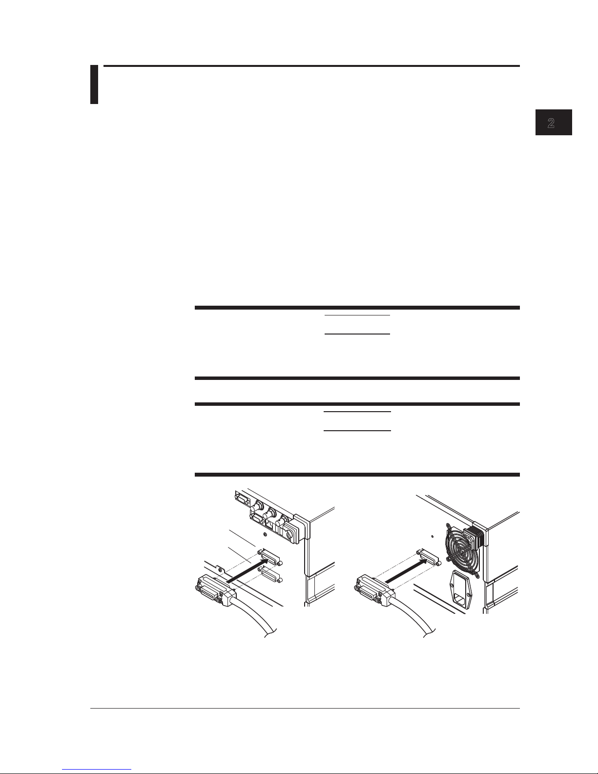
2.1 Connecting via GP-IB
GP-IB Cable
This instrument is equipped with an IEEE standard 488-1978 24-pin GP-IB connector.
Use a GP-IB cable that conforms to the IEEE standard 488-1978.
Connections
The instrument has two ports, GP-IB1 and GP-IB2. The GP-IB port on the AQ6370D/
AQ6373B/AQ6375B corresponds to the GP-IB1 port. The GP-IB2 port is not available on
the AQ6370D/AQ6373B/AQ6375B.
GP-IB1 port: Can be connected to a PC for remote control of the instrument from the PC.
GP-IB2 port: Can be connected to another instrument for remote control of that
instrument using the AQ6370C/AQ6373/AQ6375’s program function.
For now, you will connect a PC to the GP-IB1 port.
Turn OFF all the power switches of the AQ6370C/AQ6370D/AQ6373/AQ6373B/AQ6375/
AQ6375B and any devices to be connected to it. Connect a cable to the GP-IB1 port on
the rear panel of the instrument.
CAUTION
Always turn OFF the power to the instrument and the PC when connecting or
disconnecting communication cables. Failure to turn OFF the power can result in
malfunction or damage to internal circuitry.
French
ATTENTION
Veillez à mettre le PC et l'oscilloscope DLM4000 hors tension lorsque vous
branchez ou débranchez les câbles de communication, car cela risquerait de
provoquer des dysfonctionnements ou des courts-circuits internes.
GP-IB1
GP-IB2
AQ6370C/AQ6373/AQ6375 AQ6370D/AQ6373B/AQ6375B
Chapter 2 GP-IB Interface (GP-IB1 Port)
Page 15
2-2
IM AQ6370C-17EN
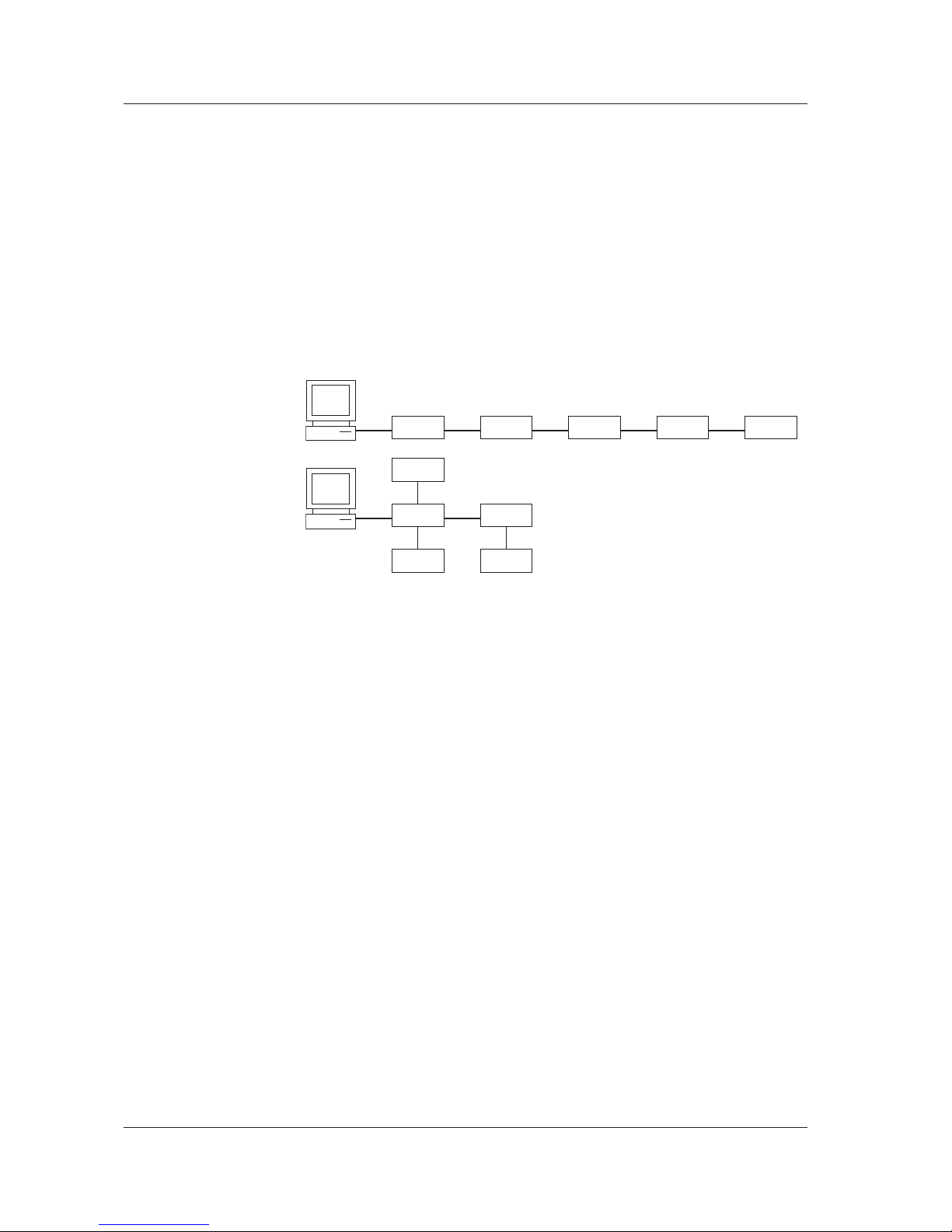
Precautions When Making Connections
• Securely fasten the screw that is attached to the GP-IB cable connector.
• You can connect several cables to connect to several devices. However, fifteen or
more devices including the controller cannot be connected to a single bus.
• When connecting several devices, you cannot specify the same address for more than
one.
• Use a cable of two meters or longer to connect between devices.
• Ensure that the total length in cables does not exceed twenty meters.
• When carrying out communications, make sure that at least two-thirds of all connected
devices are turned ON.
• When connecting multiple devices, use a star or linear configuration as shown in the
figure below. A loop or parallel configuration cannot be used.
2.1 Connecting via GP-IB
Page 16

2-3
IM AQ6370C-17EN
GP-IB Interface (GP-IB1 Port)
1
2
2.2 GP-IB Interface Function
GP-IB Interface Function
Listener Function
• All of the same settings can be performed using the interface (except for power ON/
OFF and communication settings) as when using the instrument’s panel keys.
• Settings, waveforms, and other data can be received through output commands from
the controller.
• Additionally, you can also receive commands regarding status reports and other data.
Talker Function
• Settings, waveforms, and other data can be output.
Note
Listen only, talk only, and controller functions are not available.
Switching between Remote and Local
Switching from Local to Remote
When in Local mode, if the instrument received a listen address from the controller that
sets REN (remote enable) and ATN to “True,” the instrument enters Remote mode.
• When in Remote mode, the REMOTE indicator lights.
• Keys other than the LOCAL key are disabled.
• Settings entered in Local mode are held even if switching to Remote mode.
• When an LLO (Local Lock Out) message is received from the controller, the
instrument enters local lockout status. In LLO status, the LOCAL key is disabled and
does not return this instrument to Local mode even when pressed. After cancelling the
local lockout status, press the LOCAL key. To cancel the local lockout status, set REN
to "False" from the controller.
Switching from Remote to Local
If you press the LOCAL key when in Remote mode the instrument enters Local mode.
However, it does not return to Local mode if in the local lockout state.
• The REMOTE indicator turns off.
• All keys are enabled.
• Settings entered in Remote mode are held even if switching to Local mode.
• When a GTL (Go to Local) message is received from the controller, the instrument
enters Local mode even if REN is set to False.
Note
The GP-IB interface cannot be used simultaneously with other communication interfaces
(RS-232, USB, or Ethernet).
Page 17

2-4
IM AQ6370C-17EN
2.3 GP-IB Interface Specifications
GP-IB Interface Specifications
Electromechanical specifications: Conforms to IEEE std. 488-1978
Functional specifications: See table below
Protocols: Conforms to IEEE std. 488.2-1992
Encoding: ISO (ASCII)
Mode: Addressable mode
Address setting: Addresses 0 to 30 can be set in the GP-IB setting
screen in the SYSTEM menu.
Remote mode cancel: Press LOCAL to cancel Remote mode. Note that
this is disabled when under Local Lockout by the
controller.
Functional Specifications
Function Subset Description
Source handshake SH1 All capabilities of send handshake
Acceptor handshake AH1 All capabilities of receive handshake
Talker T6 Basic talker function, serial polling, and talker
cancel function through MLA (my listen address).
Talker only not provided.
Listener L4 Basic listener function, serial polling, and listener
cancel function through MLA (my listen address).
Listener only not provided.
Service request SR1 All service request functions
Remote local RL1 All Remote/Local functions
Parallel port PP0 Parallel polling function not provided
Device clear DC1 All device clear functions
Output buffer clear
Input buffer clear (clearing of an unexecuted
commands)
Error buffer clear
STB, ESR clear
Device trigger DT0 Device trigger function
Controller C0 Controller function not provided
Electrical characteristics E1 Open collector
Page 18
2-5
IM AQ6370C-17EN
GP-IB Interface (GP-IB1 Port)
1
2
2.4 Setting the GP-IB Address
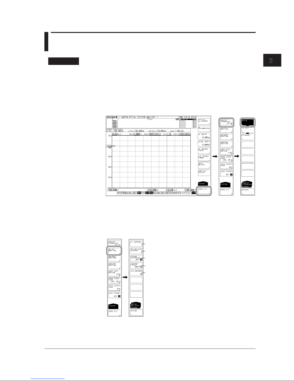
Procedure
Selecting the Communication Interface
1.
Press SYSTEM. The system setting menu is displayed.
2.
Press the MORE1/4 soft key. The communication interface setting menu is
displayed.
3.
Press the REMOTE INTERFACE soft key. The setting menu for the interface to
be used is displayed.
4.
Press the GP-IB soft key to specify GP-IB as the communication interface.
Setting the Address
5.
Press the GP-IB SETTING soft key. The GP-IB setting menu is displayed.
6.
Press the MY ADDRESS soft key. The GP-IB address setting screen is displayed.
7.
Set the GP-IB address using the rotary knob or the arrow keys, and press
ENTER.
GP-IB address setting
See chapter 5
Command format
See chapter 5
See chapter 5
Page 19

2-6
IM AQ6370C-17EN
Setting the Command Format
8.
Perform these steps if you will use AQ6317 commands. Press the COMMAND
FORMAT soft key. The command format setting menu is displayed.
9.
Normally, you will enter AQ6370C, AQ6370D, AQ6373, AQ6373B, AQ6375 or
AQ6375B. If you wish to use AQ6317 commands, enter AQ6317.
Explanation
The settings below are used when entering the settings that can be entered using the
instrument’s panel keys from a controller, or when outputting settings or waveform data
to the controller.
GP-IB Address Settings
When in Addressable mode, set the instrument’s address within the following range.
0 to 30
Each device that can be connected via GP-IB has its own unique GP-IB address. This
address allows each device to be distinguished from other devices. Therefore, when
connecting the instrument to a PC or other device, make sure not to set the same
address on the instrument as any of the other devices.
Note
• Do not change an address while the controller or other devices are using GP-IB.
• Set addresses other than those used by the GP-IB2 port.
Command Format Settings
Normally, you will enter AQ6370C, AQ6370D, AQ6373, AQ6373B, AQ6375 or AQ6375B
mode.
If you wish to use the commands of the AQ6317 (another product in the series), enter
AQ6317. See the appendix for AQ6317 commands that are compatible with the AQ6317.
Note
Controller functions and TLS address settings are entered when controlling an external device
using the GP-IB2 port. These settings are invalid for the GP-IB1 port.
2.4 Setting the GP-IB Address
Page 20

2-7
IM AQ6370C-17EN
GP-IB Interface (GP-IB1 Port)
1
2
2.5 Responses to Interface Messages
Responses to Interface Messages
Responses to Uniline Messages
IFC (Interface Clear)
Clears talker and listener. Output is cancelled if outputting data.
REN (Remote Enable)
Switches between Local and Remote.
IDY (Identify) is not supported.
Responses to Multiline Messages (Address Commands)
GTL (Go To Local)
Switches to Local mode.
SDC (Selected Device Clear)
• Clears program messages (commands) being received, and the output queue.
• The *OPC and *OPC? commands are invalid during execution.
• The *WAI command closes immediately.
PPC (parallel poll configure), GET (group execute trigger), and TCT (take control) are not
supported.
Responses to Multiline Messages (Universal Commands)
LLO (Local Lockout)
Disables the front panel SHIFT+CLEAR operation, and prohibits switching to Local
mode.
DCL (Device Clear)
Same operation as SDC.
SPE (Serial Poll Enable)
Places the talker function of all devices on the bus in Serial poll mode. The controller
polls each device in order.
SPD (Serial Poll Disable)
Cancels Serial poll mode for the talker function of all devices on the bus.
PPU (Parallel Poll Unconfigure) is not supported.
Definition of Interface Messages
Interface messages are also called interface commands or bus commands, and are
commands that are issued from the controller. Interface messages come in the following
categories.
Uniline Messages
A message is sent through a single command line. The following are the three types of
uniline messages.
IFC (Interface Clear)
REN (Remote Enable)
IDY (Identify)
Page 21

2-8
IM AQ6370C-17EN
Multiline Messages
A message is sent through eight data lines. Multiline messages come in the following
categories.
Address Commands
These commands are valid when the device is specified as the listener or the talker.
The following are the five types of address commands.
Commands valid for devices specified as listeners
GTL (Go To Local)
SDC (Selected Device Clear)
PPC (Parallel Poll Configure)
GET (Group Execute Trigger)
Commands valid for devices specified as talkers
TCT (Take Control)
Universal Commands
These commands are valid for all devices regardless of whether they are specified as
listeners, talkers, or neither. The following are the three types of universal commands.
LLO (Local Lockout)
DCL (Device Clear)
PPU (Parallel Poll Unconfigure)
Additionally, an interface message can consist of a listener address, talker address, or
secondary command.
Interface Messages
Uniline
messages
Address
commands
Universal
commands
IFC
REN
IDY
GTL
SDC
PPC
GET
TCT
LLO
DCL
PPU
SPE
SPD
Listener
address
Talker
address
Secondary
command
Multiline messages
A star indicates an interface message supported by this instrument.
Note
Differences between SDC and DCL
Of the multiline messages, SDC is an address command requires specification of the talker
or listener, and DCL is a universal command that does not require specification of the talker
or listener. Therefore, SDC is applicable only to certain devices, but DCL is applicable to all
devices on the bus.
2.5 Responses to Interface Messages
Page 22

2-9
IM AQ6370C-17EN
GP-IB Interface (GP-IB1 Port)
1
2
2.6 Sample Program
The following shows an example of controlling the AQ6370C/AQ6370D/AQ6373/AQ6373B/
AQ6375/AQ6375B remotely using the GP-IB port. The sample program uses Visual Basic
6.0 as the programming language. Also, a GP-IB board by National Instruments (hereinafter,
“NI”) is used as the GP-IB controller and the NI-supplied driver is used as a library.
Sample Program 1
The program sets the measurement conditions (center wavelength, span, sensitivity,
and the sampling number) and then performs a sweep. After completing this sweep, the
program executes a thresh-based spectrum width analysis and then outputs the results
to the screen.
Const BOARD_ID = 0 ' GP-IB Interface card
Address
Const osa = 1 ' OSA GP-IB Address
Private Sub AQ637XTEST()
Dim intData As Integer
Dim dblMeanWL As Double
Dim dblSpecWd As Double
Dim strData As String
' === GP-IB Interface setting ===
' send IFC
Call SendIFC(BOARD_ID)
' assert th REN GPIB line
intAddrList(0) = NOADDR
Call EnableRemote(BOARD_ID, intAddrList())
' GPIB time out setting
Call ibtmo(BOARD_ID, T30s) ' Time out = 30sec
' === Set the measurement parameter ===
Call SendGPIB(osa, "*RST") ' Setting initialize
Call SendGPIB(osa, "CFORM1") ' Command mode
set(AQ637X mode)
Call SendGPIB(osa, ":sens:wav:cent 1550nm") ' sweep center wl
Call SendGPIB(osa, ":sens:wav:span 10nm") ' sweep span
Call SendGPIB(osa, ":sens:sens mid") ' sens mode = MID
Call SendGPIB(osa, ":sens:sweep:points:auto on")
' Sampling Point = AUTO
' === Sweep execute ===
Call SendGPIB(osa, ":init:smode 1") ' single sweep mode
Call SendGPIB(osa, "*CLS") ' status clear
Call SendGPIB(osa, ":init") ' sweep start
' === Wait for sweep complete ===
Do
Call SendGPIB(osa, ":stat:oper:even?") ' get Operation Event
Register
strData = RecieveGPIB(osa)
intData = Val(strData)
Loop While ((intData And 1) <> 1) ' Bit0: Sweep status
' === Analysis ===
Call SendGPIB(osa, ":calc:category swth") ' Spectrum width
analysis(THRESH type)
Call SendGPIB(osa, ":calc") ' Analysis Execute
Call SendGPIB(osa, ":calc:data?") ' get data
strData = RecieveGPIB(osa)
Page 23

2-10
IM AQ6370C-17EN
' === Capture analytical results ===
dblMeanWL = Val(Left(strData, 16)) ' get mean wavelegnth
dblSpecWd = Val(Mid(strData, 18, 16)) ' get spectrum width
' === Output the result to the screen ===
MsgBox ("MEAN WL: " & dblMeanWL * 1000000000# & " nm" & vbCrLf & _
"SPEC WD: " & dblSpecWd * 1000000000# & " nm")
' === Disconnect ===
Call EnableLocal(BOARD_ID, intAddrList())
End Sub
'==================================================
' Sub routine
' Send Remote Command
'==================================================
Sub SendGPIB(intAddr As Integer, strData As String)
Call Send(BOARD_ID, intAddr, strData, NLend)
If (ibsta And EERR) Then
MsgBox " GP-IB device can't write"
End If
End Sub
'==================================================
' Sub routine
' Recieve query data
'==================================================
Function RecieveGPIB(intAddr As Integer) As String
Const READSIZE = 10000
Dim strBuffer As String
strBuffer = Space(READSIZE)
RecieveGPIB = ""
Do
DoEvents
Call Receive(BOARD_ID, intAddr, strBuffer, STOPend)
If (ibsta And EERR) Then
MsgBox " GP-IB device can't read."
RecieveGPIB = ""
Exit Function
Else
RecieveGPIB = RecieveGPIB & Left(strBuffer, ibcntl)
End If
Loop Until ((ibsta And EEND) = EEND)
End Function
2.6 Sample Program
Page 24

2-11
IM AQ6370C-17EN
GP-IB Interface (GP-IB1 Port)
1
2
Sample Program 2
Save an image of the instrument's screen to a BMP file, then use a file transfer command
to load the file onto the PC. Save the image on the PC under the file name, "C:\test.
bmp".
Const BOARD_ID = 0 'GP-IB Interface card Address
Const osa = 1 'OSA GP-IB Address
Private Sub Command1_Click()
Dim intAddrList(31) As Integer
Dim intData As Integer
Dim lngDataSize As Long
Dim strData As String
Dim intI As Integer
Dim byteData() As Byte
Dim byteSaveData() As Byte
Dim lngL As Long
'----- GP-IB Interface setting
' send IFC
Call SendIFC(BOARD_ID)
' assert th REN GPIB line
intAddrList(0) = NOADDR
Call EnableRemote(BOARD_ID, intAddrList())
' GPIB time out setting
Call ibtmo(BOARD_ID, T30s) 'Time out = 30sec
'----- send command to OSA
Call SendGPIB(osa, "CFORM1") ' Command mode set(AQ637X mode)
Call SendGPIB(osa, ":mmem:stor:grap color,bmp,""test"",int")
' Save bmp file to internal memory
Call SendGPIB(osa, ":mmem:data? ""test.bmp"",int")
' get file data from OSA
lngDataSize = RecieveBinaryGPIB(osa, byteData())
' Recieve binary block data
If byteData(0) <> Asc("#") Then ' check first data
MsgBox "Data format error"
Exit Sub
End If
'----- calculate data size
intData = byteData(1) - Asc("0")
strData = ""
For intI = 1 To intData
strData = strData + Chr(byteData(intI + 1))
Next intI
lngDataSize = Val(strData) ' data size
'----- make save data
ReDim byteSaveData(lngDataSize)
For lngL = 0 To lngDataSize - 1
byteSaveData(lngL) = byteData(lngL + intData + 2)
Next lngL
'----- save data to file
Open "c:\test.bmp" For Binary As #1
Put #1, , byteSaveData
Close #1
'----- Disconnect
Call EnableLocal(BOARD_ID, intAddrList())
MsgBox "Complete"
End Sub
2.6 Sample Program
Page 25

2-12
IM AQ6370C-17EN
'==================================================
' Sub routine
' Send Remote Command
'==================================================
Sub SendGPIB(intAddr As Integer, strData As String)
Call Send(BOARD_ID, intAddr, strData, NLend)
If (ibsta And EERR) Then
MsgBox " GP-IB device can't write"
End If
End Sub
'==================================================
' Sub routine
' Recieve Binary query data
'==================================================
Function RecieveBinaryGPIB(intAdr As Integer, byteArray() As Byte) As
Long
Const READSIZE = 1200000 ' MAX 1.2MB
Dim lngSize As Long
Dim lngL As Long
Dim lngPos As Long
Dim ud As Integer
Dim byteLow As Byte
Dim byteHigh As Byte
Dim strA As String
Dim intDummy(READSIZE) As Integer
lngSize = 0
'----- open device
ud = ildev(0, intAdr, 0, T30s, 1, 0)
lngPos = 0
'----- read data
Do
DoEvents
Call ibrdi(ud, intDummy, READSIZE)
If (ibsta And EERR) Then
MsgBox "GP-IB device can't Read(GPIB:" & intAdr & ")"
RecieveBinaryGPIB = 0
Exit Function
Else
ReDim Preserve byteArray(lngPos + ibcntl + 2)
For lngL = 0 To ibcntl / 2 - 1
strA = Right("0000" & Hex(intDummy(lngL)), 4)
byteHigh = Val("&H" + Left(strA, 2))
byteLow = Val("&H" + Right(strA, 2))
byteArray(lngPos) = byteLow
byteArray(lngPos + 1) = byteHigh
lngPos = lngPos + 2
Next lngL
End If
Loop While (ibcntl = READSIZE)
RecieveBinaryGPIB = lngPos
End Function
2.6 Sample Program
Page 26
3-1
IM AQ6370C-17EN
Ethernet Interface
1
2
3
3.1 Connecting via Ethernet
You can connect to a LAN using the Ethernet interface for control of the instrument from
a PC.
Ethernet Interface Specifications
Communication ports: 1
Electromechanical specifications: Conforms to IEEE802.3
Transmission method: Ethernet (10BASE-T/100BASE-TX/
1000BASE-T (AQ6370D/AQ6373B/AQ6375B only))
Transmission speed: 10 Mbps/100 Mbps/1000 Mbps (AQ6370D/AQ6373B/
AQ6375B only)
Communication protocol: TCP/IP
Connector type: RJ45
Port number used: 10001/tcp (default)
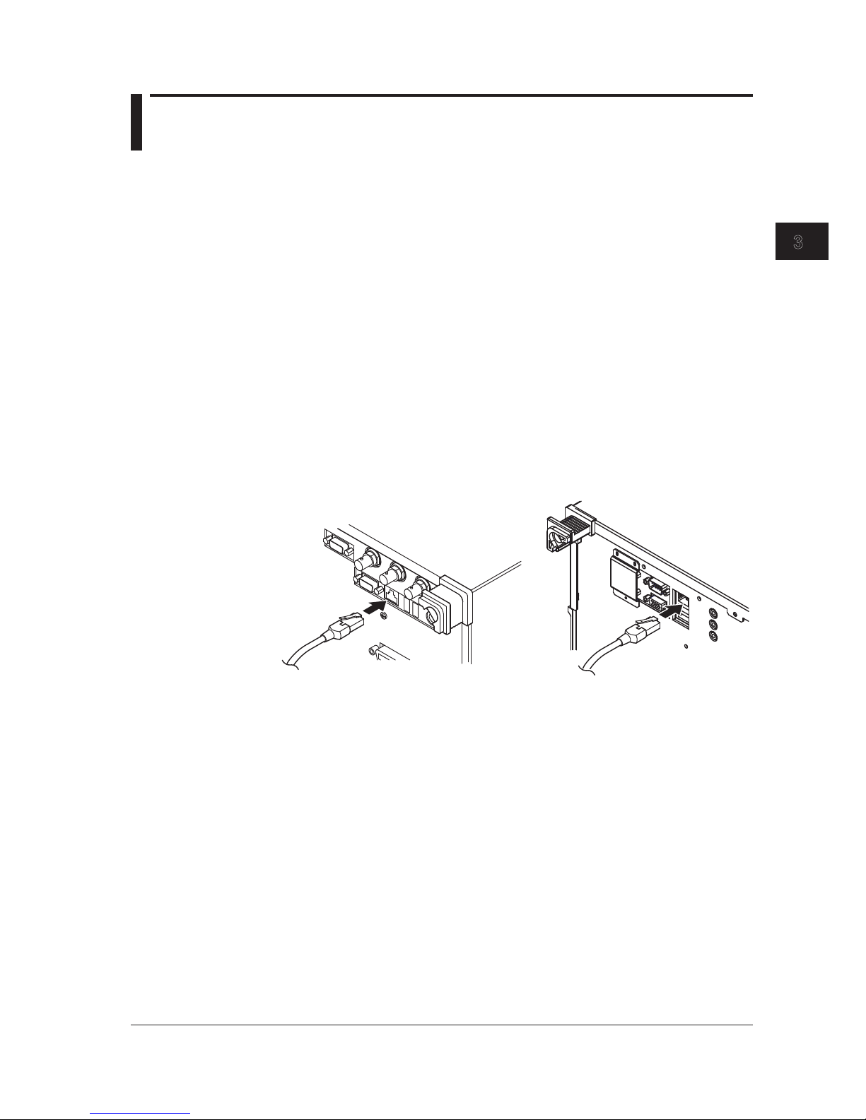
Connections
Connect a UTP (unshielded twisted-pair) cable or an STP (shielded twisted-pair) cable
that is connected to another device to the ETHERNET port on the rear panel of the
instrument.
AQ6370C/AQ6373/AQ6375
AQ6370D/AQ6373B/AQ6375B
Precautions When Making Connections
• Be sure to use a straight cable through a hub when connecting a PC to the instrument.
Performance cannot be guaranteed if a 1-to-1 connection is made with a cross cable.
• When using a UTP (straight) cable, make sure that it is a category 5 cable.
Chapter 3 Ethernet Interface
Page 27
3-2
IM AQ6370C-17EN
3.2 Setting Up Ethernet
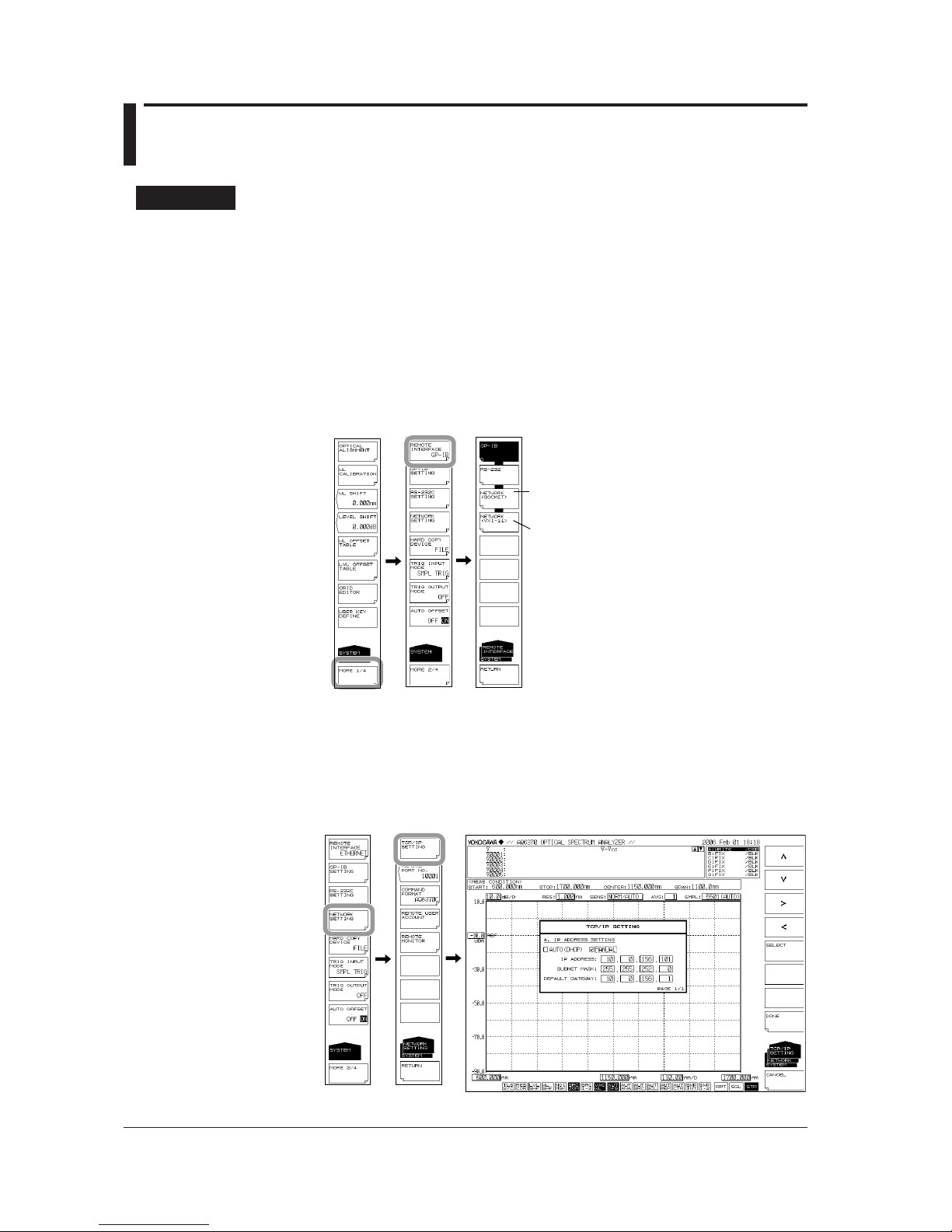
Procedure
Selecting the Communication Interface
1.
Press SYSTEM. The system setting menu is displayed.
2.
Press the MORE1/4 soft key. The communication interface setting menu is
displayed.
3.
Press the REMOTE INTERFACE soft key. The setting menu for the interface to
be used is displayed.
4.
In AQ6370D (R02.01 or later), press the
NETWORK(SOCKET)
or
NETWORK(VXI-11)
soft key to set the communication interface to Ethernet.
In models other than AQ6370D, press the ETHERNET soft key to set the
communication interface to Ethernet.
NETWORK(SOCKET)(AQ6370D)
NETWORK(except for AQ6370D)
NETWORK(VXI-11)(AQ6370D)
Setting Up TCP/IP
5.
Press the NETWORK SETTING soft key. The ethernet setting menu is displayed.
6.
Press the TCP/IP SETTING soft key. The TCP/IP setting menu is displayed.
7.
Using the <, > soft keys, select AUTO (DHCP) or MANUAL.
8.
Press the SELECT soft key. The item is selected.
Page 28

3-3
IM AQ6370C-17EN
Ethernet Interface
1
2
3
9.
If you select MANUAL, enter the IP address, subnet mask, and default gateway.
Using the arrow soft keys, select an input position, and press ENTER. If you
selected AUTO, skip to step 10.
10.
Enter a number using the rotary knob or the <, >,
<
>
,
keys, and press ENTER.
11.
When all settings are entered, press the DONE soft key.
Setting the Remote Port Number (not used with the VXI-11)
12.
Press the REMOTE PORT NO. soft key. The port number setting screen is
displayed.
13.
Enter a port number using the rotary knob or the arrow keys, and press ENTER.
Command format setting
Remote port number setting
Setting the Command Format
14.
Perform these steps if you will use AQ6317 commands.
Press the COMMAND FORMAT soft key. The command format setting menu is
displayed.
15.
Normally, you will enter AQ6370C, AQ6370D, AQ6373, AQ6373B, AQ6375 or
AQ6375B. If you wish to use AQ6317 commands, enter AQ6317.
Setting the User Name and Password (not used with the VXI-11)
16.
Press the REMOTE USER ACCOUNT soft key. The user name and password
setting menu is displayed.
17.
Press the USER NAME soft key. The user name setting screen appears. The
default is anonymous.
18.
Specify a user name using 11 alphanumeric characters or fewer.
If the user name is set to anonymous, the password setting is not required.
19.
Press the PASSWORD soft key. The password setting screen is displayed.
20.
Specify a password using 11 alphanumeric characters or fewer.
3.2 Setting Up Ethernet
Page 29

3-4
IM AQ6370C-17EN
Configuring the Remote Monitor Settings (On the AQ6370C/AQ6370D/
AQ6373B/AQ6375B)
21.
Press the REMOTE MONITOR soft key. The remote monitor setup menu appears.
22.
Press the MONITOR PORT soft key. Each time you press the soft key, the setting
toggles between ON and OFF. Remote monitoring is possible when the setting is
ON.
Turns the monitor port on and off.
Set the port number (fixed).
Disconnects the monitor connection
• Disconnecting the Monitor Connection
23.
Press the DISCONNECT soft key. The monitor connection from the PC is
disconnected.
Setting Directory Sharing (Only on the AQ6370D/AQ6373B/AQ6375B)
24.
Press the FOLDER SHARING soft key. A directory sharing setup menu appears.
25.
Press the READ ONLY soft key. The user area directory of the AQ6370D/
AQ6373B/AQ6375B is shared (read only).
Disables directory sharing
Enables directory sharing
• Disabling Directory Sharing
26.
Press the DISABLE soft key. The sharing of the user area directory is disabled.
Explanation
TCP/IP Settings
It is necessary to set up the IP address for correct use of the instrument.
If a DHCP server is provided on the network to which this instrument is connected, the
IP address given to the instrument is automatically set. Thus, set the item IP ADDRESS
SETTING under SYSTEM <NETWORK SETTING><TCP/IP SETTING> to “AUTO.”
Please ask your network administrator for details about network connections.
Note
• If you start the AQ6370C/AQ6370D/AQ6373/AQ6373B/AQ6375/AQ6375B when it is
connected to a network, it may take a few minutes for the start procedure to finish. (The
progress of initialization is indicated at the bottom of the screen with indications from “STEP
1/9” to “STEP 9/9.”)
• When the start procedure is finished and the measurement screen appears, it may take
a few more minutes before you can access the AQ6370C/AQ6370D/AQ6373/AQ6373B/
AQ6375/AQ6375B from a PC over the network. In addition, the DONE key of TCP/IP
settings may be unavailable for a certain time.
3.2 Setting Up Ethernet
Page 30

3-5
IM AQ6370C-17EN
Ethernet Interface
1
2
3
REMOTE PORT NO. (not used with the VXI-11)
Sets the port number for remote control via ETHERNET. (Default: 10001.)
User Authentication
(not used with the VXI-11)
User authentication is required to connect to the instrument from a PC over an Ethernet
network. If the user name is anonymous, a password is not required. This instrument
supports plain text authentication and the MD5 Message Digest Algorithm by RSA Data
Security, Inc.
Remote Monitoring
You can use the ETHERNET port to monitor the AQ6370C/AQ6370D/AQ6373B/AQ6375B
screen or control the AQ6370C/AQ6370D/AQ6373B/AQ6375B from a PC over a network.
To use this feature, you need remote monitoring software (not included).
For information on remote monitoring software, contact your nearest YOKOGAWA dealer.
Sharing Directories
The user area directory of the AQ6370D/AQ6373B/AQ6375B internal memory can be
shared on a PC.
When the user area directory is shared, the following files can be copied to the PC over
the network.
You cannot save files to the AQ6370D/AQ6373B/AQ6375B.
Timeout Period (AQ6370D (R02.01 or later))
This is enabled when REMOTE INTERFACE is NETWORK (SOCKET).
When a non-communication period reached the set period in a remote state, the
communication is automatically disconnected to enter the local state.
The change in the timeout period resets the time elapsed.
You can set INFINITE (0 second) or 1 through 21600 seconds (six hours).
Remote Control Using Commands
The AQ6370C/AQ6370D/AQ6373/AQ6373B/AQ6375/AQ6375B can be remote controlled
using the LAN port.
For remote commands, use the same commands as those for control via the GP-IB
interface.
AQ6370D (R02.01 or later) also supports control with VXI-11.
Switching Interfaces
Select GP-IB, RS-232C, or ETHERNET as an interface to use for remote control. When
set to ETHERNET, the LAN mode connection status is reset. Otherwise, the connection
is kept open unless closed by the controller.
Remote Commands
As with GP-IB-based remote control, you can select the command format from the
AQ6370C, AQ6370D, AQ6373, AQ6373B, AQ6375 or AQ6375B mode or from the
AQ6317-compatible mode.
Interrupt by SRQ
An SRQ interrupt does not occur during LAN-based remote control.
3.2 Setting Up Ethernet
Page 31

3-6
IM AQ6370C-17EN
Status Register
The status registers operate in the same manner as in remote control via the GP-IB
interface. Using the “*SPOOL?” command dedicated for remote control using the LAN
port allows you to read the status registers, as in the case with serial polling via the GPIB interface.
*STB?: When AQ6370C/AQ6370D/AQ6373/AQ6373B/AQ6375/AQ6375B is the
setting of the COMMAND FORMAT key
SPOLL?: When AQ6317 is the setting of the COMMAND FORMAT key
Delimiter
The delimiter for LAN-based remote control is fixed to CR + LF.
Transmission of Talker Data
When the instrument receives talker data from an external PC, it sends the data to the
external PC's buffer. It receives the external PC's buffer data and stores the query data.
Connection
The instrument can only be connected to one controller (an external PC or other device).
If the instrument receives a connection request from a controller while already connected
to another controller, the new connection is not opened and the existing connection is
kept open.
Computer Name
The instrument’s computer name is as follows.
For the AQ6370C,
“6370C@@@@@@@@@” (where “@@@@@@@@@” is the serial number)
For the AQ6370D,
“6370D@@@@@@@@@” (where “@@@@@@@@@” is the serial number)
For the AQ6373,
“6373@@@@@@@@@” (where “@@@@@@@@@” is the serial number)
For the AQ6373B,
“AQ6373B@@@@@@@@@” (where “@@@@@@@@@” is the serial number)
For the AQ6375,
“AQ6375@@@@@@@@@” (where “@@@@@@@@@” is the serial number)
For the AQ6375B,
“AQ6375B@@@@@@@@@” (where “@@@@@@@@@” is the serial number)
The machine number is a 9-digit alphanumeric number on the back of the unit. You can
not change the computer name.
3.2 Setting Up Ethernet
Page 32

3-7
IM AQ6370C-17EN
Ethernet Interface
1
2
3
Commands that are Necessary for Remote Control over the LAN
The authentication
by OPEN command
is required to remote control over
the LAN.
Both the OPEN and CLOSE commands are also valid in AQ6317 mode.
OPEN
Function Sends the user name and starts user authentication.
Syntax
OPEN<wsp>"username"
username = the user name
Example
OPEN "yokogawa"
-> AUTHENTICATE CRAM-MD5.
Explanation Authentication is carried out with the OPEN command as follows.
For Plain Text Authentication
1. Send OPEN "username" to the AQ6370C/AQ6370D/AQ6373/AQ6373B/AQ6375/
AQ6375B. The response message is received from the AQ6370C/AQ6370D/
AQ6373/AQ6373B/AQ6375/AQ6375B.
2. Confirm that the received message is "AUTHENTICATE CRAM-MD5."
3. Send the password to the AQ6370C/AQ6370D/AQ6373/AQ6373B/AQ6375/
AQ6375B (anything can be input if the user name is anonymous).
4. If the message, "READY" is received from the AQ6370C/AQ6370D/AQ6373/
AQ6373B/AQ6375/AQ6375B, authentication was successful. The AQ6370C/
AQ6370D/AQ6373/AQ6373B/AQ6375/AQ6375B's REMOTE indicator lights, and
sending of remote commands is enabled. If the user name and password are
incorrect, authentication fails and the connections is closed.
For Encrypted Authentication
1. Send OPEN "username" to the AQ6370C/AQ6370D/AQ6373/AQ6373B/AQ6375/
AQ6375B. The response message is received from the AQ6370C/AQ6370D/
AQ6373/AQ6373B/AQ6375/AQ6375B.
2. Confirm that the received message is "AUTHENTICATE CRAM-MD5."
3. Send "AUTHENTICATE CRAM-MD5 OK" to the AQ6370C/AQ6370D/AQ6373/
AQ6373B/AQ6375/AQ6375B. The response message (challenge string) is received
from the AQ6370C/AQ6370D/AQ6373/AQ6373B/AQ6375/AQ6375B.
4. The received challenge string and password are processed with an MD5 hash
algorithm (anything can be input if the user name is anonymous).
5. Send the returned hash data (as a 32-character hexadecimal string in lower case)
to the AQ6370C/AQ6370D/AQ6373/AQ6373B/AQ6375/AQ6375B, and receive the
response message.
6. If the message, "READY" is received from the AQ6370C/AQ6370D/AQ6373/
AQ6373B/AQ6375/AQ6375B, authentication was successful. The AQ6370C/
AQ6370D/AQ6373/AQ6373B/AQ6375/AQ6375B's REMOTE indicator lights, and
sending of remote commands is enabled. If the user name and password are
incorrect, authentication fails and the connection is closed.
CLOSE
Function Closes the connection (turns it OFF), and switches to local mode.
Syntax
CLOSE
Example
CLOSE
3.2 Setting Up Ethernet
Page 33

3-8
IM AQ6370C-17EN
3.3 Sample Program
Sample Program 1
Sending an invalid talker command to the AQ6370C/AQ6370D/AQ6373/AQ6373B/
AQ6375/AQ6375B and then receiving data with the instrument specified as a talker
causes the GP-IB bus to stop because the instrument has no data to send. In this case,
a GPIB timeout occurs, followed by recovery of the GP-IB bus.
The following shows an example of controlling the AQ6370C/AQ6370D/AQ6373/
AQ6373B/AQ6375/AQ6375B remotely using the Ethernet port. The sample program
uses Visual Basic 6.0 as the programming language. The program sets the measurement
conditions (center wavelength, span, sensitivity, and the sampling number) and then
performs a sweep. After completing this sweep, the program executes a thresh-based
spectrum width analysis and then outputs the results to the screen. The conditions are
the same as those of the GP-IB sample program in section 2.6, “Sample Program.”
Private Sub AQ637XTEST()
Dim intData As Integer
Dim dblMeanWL As Double
Dim dblSpecWd As Double
Dim strData As String
' === Connect ===
Winsock1.RemoteHost = "192.168.1.100" ' OSA IP address
Winsock1.RemotePort = 10001 ' OSA remote port num
Winsock1.Connect
' === Wait to connect complete ===
While (Winsock1.State <> sckConnected)
DoEvents
Wend
' === Authentication by OPEN Command ===
SendLan "open ""anonymous"""
ReceiveLan strData
SendLan " "
ReceiveLan strData
If (Left(strData, 5) <> "ready") Then
MsgBox "User authentication error."
Exit Sub
End If
' === Set the measurement parameter ===
SendLan "*RST" ' Setting initialize
SendLan "CFORM1" ' Command mode set
(AQ637X mode)
SendLan ":sens:wav:cent 1550nm" ' sweep center wl
SendLan ":sens:wav:span 10nm" ' sweep span
SendLan ":sens:sens mid" ' sens mode = MID
SendLan ":sens:sweep:points:auto on" ' Sampling Point = AUTO
' === Sweep execute ===
SendLan ":init:smode 1" ' single sweep mode
SendLan "*CLS" ' status clear
SendLan ":init" ' sweep start
Page 34

3-9
IM AQ6370C-17EN
Ethernet Interface
1
2
3
' === Wait for sweep complete ===
Do
SendLan ":stat:oper:even?" ' get Operation Event
Register
ReceiveLan strData
intData = Val(strData)
Loop While ((intData And 1) <> 1) ' Bit0: Sweep status
' === Analysis ===
SendLan ":calc:category swth" ' Spectrum width
analysis(THRESH type)
SendLan ":calc" ' Analysis Execute
SendLan ":calc:data?" ' get data
ReceiveLan strData
' === Capture analytical results ===
dblMeanWL = Val(Left(strData, 16)) ' get mean wavelegnth
dblSpecWd = Val(Mid(strData, 18, 16)) ' get spectrum width
' === Output the result to the screen ===
MsgBox ("MEAN WL: " & dblMeanWL * 1000000000# & " nm" & vbCrLf & _
"SPEC WD: " & dblSpecWd * 1000000000# & " nm")
' === Disconnect ===
Winsock1.Close
'Wait to disconnect complete
While (Winsock1.State <> sckClosed)
DoEvents
Wend
End Sub
'==================================================
' Sub routine
' Send Remote Command
'==================================================
Sub SendLan(strData As String)
Winsock1.SendData strData & vbCrLf
DoEvents
End Sub
'==================================================
' Sub routine
' Receive query data
'==================================================
Sub ReceiveLan(strData As String)
Dim strData2 As String
strData = ""
Do
Winsock1.GetData strData2, vbString
strData = strData + strData2
DoEvents
Loop While (Right(strData, 1) <> vbLf)
End Sub
3.3 Sample Program
Page 35

3-10
IM AQ6370C-17EN
Sample Program 2
Save an image of the instrument's screen to a BMP file, then use a file transfer command
to load the file onto the PC. Save the image on the PC under the file name, "C:\test.
bmp". The conditions are the same as the GP-IB sample program in section 2.6, "Sample
Programs."
Const TIMEOUT = 1 ' time out(sec)
Private Sub cmdConnect_Click()
Dim strData As String
Dim byteData() As Byte
Dim lngDataSize As Long
'=== Connect ===
If (ConnectLan("192.168.1.100", 10001) = False) Then
MsgBox "Connection error"
Winsock1.Close
Exit Sub
End If
' === Authentication by OPEN Command ===
SendLan "open ""anonymous""" ' Send user name
lngDataSize = ReceiveLan(strData)
If (lngDataSize = -1) Then
MsgBox "Data Receive Error"
Winsock1.Close
Exit Sub
End If
SendLan " " ' Send password
lngDataSize = ReceiveLan(strData)
If (lngDataSize = -1) Then
MsgBox "Data Receive Error"
Winsock1.Close
Exit Sub
End If
If (Left(strData, 5) <> "ready") Then
MsgBox "User authentication error."
Winsock1.Close
Exit Sub
End If
'----- send command to OSA
Call SendLan("CFORM1") ' Command mode
set(AQ637X mode)
Call SendLan(":mmem:stor:grap color,bmp,""test"",int")
' Save bmp file to internal memory
Call SendLan(":mmem:data? ""test.bmp"",int") ' get file data from
OSA
lngDataSize = ReceiveBinaryLan(byteData()) ' Recieve binary block
data
'----- save data to binary file
Open "c:\test.bmp" For Binary As #1
Put #1, , byteData
Close #1
'----- Disconnect
Winsock1.Close
'Wait to disconnect complete
While (Winsock1.State <> sckClosed)
DoEvents
Wend
MsgBox "Complete"
End Sub
3.3 Sample Program
Page 36

3-11
IM AQ6370C-17EN
Ethernet Interface
1
2
3
'==================================================
' Sub routine
' Connect OSA via ETHERNET
' in: strIP IP Address(Ex. "192.168.1.100") or Computer Name
' intPort port number (Ex. 10001)
' out: none
' ret: OK/NG true: OK, false: NG
'==================================================
Function ConnectLan(strIP As String, intPort As Integer) As Boolean
Dim sglStart As Single
Dim sglEnd As Single
Dim sglNow As Single
Dim bConnect As Boolean
sglStart = Timer()
sglEnd = sglStart + TIMEOUT
bConnect = True
' === Connect ===
Winsock1.RemoteHost = strIP ' OSA IP address
Winsock1.RemotePort = intPort ' OSA remote port num
Winsock1.Connect
' === Wait to connect complete ===
While ((Winsock1.State <> sckConnected) And (bConnect = True))
DoEvents
' Timeout check
sglNow = Timer()
If (sglNow < sglStart) Then sglNow = sglNow + 86400
If sglNow >= sglEnd Then bConnect = False
Wend
'----- return value set
ConnectLan = bConnect
End Function
'==================================================
' Sub routine
' Send Remote Command
'==================================================
Sub SendLan(strData As String)
Winsock1.SendData strData & vbCrLf
DoEvents
End Sub
'==================================================
' Sub routine
' Receive query data
' in: none
' out: strData Receive data
' ret: Receive data size (Error: -1)
'==================================================
Function ReceiveLan(strData As String) As Long
Dim strData2 As String
Dim sglStart As Single
Dim sglEnd As Single
Dim sglNow As Single
Dim bTimeout As Boolean
sglStart = Timer()
sglEnd = sglStart + TIMEOUT
bTimeout = False
3.3 Sample Program
Page 37

3-12
IM AQ6370C-17EN
strData = ""
Do
' data receive
DoEvents
Winsock1.GetData strData2, vbString
strData = strData + strData2
' Timeout check
sglNow = Timer()
If (sglNow < sglStart) Then sglNow = sglNow + 86400
If sglNow >= sglEnd Then bTimeout = True
Loop While ((Right(strData, 1) <> vbLf) And (bTimeout = False))
' return value set
If bTimeout = True Then
ReceiveLan = -1
Else
ReceiveLan = Len(strData)
End If
End Function
'====================================================================
' Sub routine
' Recieve Binary query data
' in: none
' out: byteArray Receive data (byte array)
' ret: Receive data size (Error: -1)
'====================================================================
Function ReceiveBinaryLan(byteArray() As Byte) As Long
Dim lngPos As Long
Dim lngTempPos As Long
Dim bData As Byte
Dim intI As Integer
Dim intJ As Integer
Dim strA As String
Dim lngDataLength As Long
Dim byteDummy() As Byte
Dim sglStart As Single
Dim sglEnd As Single
Dim sglNow As Single
Dim bTimeout As Boolean
sglStart = Timer()
sglEnd = sglStart + TIMEOUT
bTimeout = False
'------------------------------------------ ' Header block
'------------------------------------------ Call ReadIPBin(bData) ' Receive 1byte
If bData = Asc("#") Then
Call ReadIPBin(bData) ' Receive 1byte
intI = bData - Asc("0")
strA = ""
For intJ = 0 To intI - 1
Call ReadIPBin(bData) ' Receive 1byte
strA = strA + Chr(bData)
Next intJ
lngDataLength = Val(strA) ' block data size
ReDim byteArray(lngDataLength)
3.3 Sample Program
Page 38

3-13
IM AQ6370C-17EN
Ethernet Interface
1
2
3
'----------------------------- ' Recieve binary data block
'----------------------------- lngPos = 0
lngTempPos = 0
ReDim byteDummy(lngDataLength)
Winsock1.GetData byteDummy, vbArray + vbByte, lngDataLength
' Receive binary data
Do
DoEvents
If (lngTempPos > UBound(byteDummy)) Then
Winsock1.GetData byteDummy, vbArray + vbByte, lngDataLength
' Continue to receive
lngTempPos = 0
Else
byteArray(lngPos) = byteDummy(lngTempPos)
lngPos = lngPos + 1
lngTempPos = lngTempPos + 1
End If
'Timeout check
sglNow = Timer()
If (sglNow < sglStart) Then sglNow = sglNow + 86400
If sglNow >= sglEnd Then bTimeout = True
Loop Until ((lngPos = lngDataLength) Or (bTimeout = True))
End If
' return value set
If bTimeout = True Then
ReceiveBinaryLan = -1
Else
ReceiveBinaryLan = lngDataLength
End If
End Function
'====================================================================
' Read binary data(1byte)
'====================================================================
Sub ReadIPBin(byteData As Byte)
Dim sglStart As Single
Dim sglEnd As Single
Dim sglNow As Single
Dim bTimeout As Boolean
sglStart = Timer()
sglEnd = sglStart + TIMEOUT
bTimeout = False
'----- wait until data received or timeout
Do
DoEvents
'Timeout check
sglNow = Timer()
If (sglNow < sglStart) Then sglNow = sglNow + 86400
If sglNow >= sglEnd Then bTimeout = True
Loop Until ((Winsock1.BytesReceived > 1) Or (bTimeout = True))
Winsock1.GetData byteData, vbByte, 1 ' 1byte read
End Sub
3.3 Sample Program
Page 39

4-1
IM AQ6370C-17EN
Serial (RS-232) Interface
1
2
3
4
4.1 Connecting via the Serial (RS-232) Interface
Serial Interface Functions and Specifications
Receive Function
You can enter the same settings as can be entered with front panel keys.
A settings output request is received.
Send Function
You can output settings and measured results.
Serial (RS-232) Interface Specifications
Electrical characteristics: Conforms to the EIA-574 standard (EIA-232 (RS-232), 9-pin)
Connection type: Point-to-point
Communication method: Full duplex
Synchronization method: Start-stop synchronization
Baud rate: 1200, 2400, 4800, 9600, 19200, 38400, 57600, 115200
Start bit: 1 bit, fixed
Data length: 8 bit, fixed
Parity: Odd, Even, or None
Stop bit: 1 bit, fixed
Connector: DELC-J9PAF-13L6 (JAE or equivalent)
Flow control: Hardware handshaking using RS/CS or Non (selectable).
Connection
Make the connection as shown in the figure below.
AQ6370D/AQ6373B/AQ6375B
AQ6370C/AQ6373/AQ6375
Chapter 4 Serial (RS-232) Interface
Page 40

4-2
IM AQ6370C-17EN
Connector and Signal Names
DELC-J9PAF-13L6 or equivalent
4
5
3
2
1
9
8
7
6
2 RD (received data): Data received from the PC.
Signal direction....input
3 SD (send data): Data sent to the PC.
Signal direction....output
5 SG (signal ground): Ground for the signal.
7 RS (request to send): Handshaking method when receiving data from the PC.
Signal direction....output
8 CS (clear to send): Handshaking method when sending data to the PC.
Signal direction....input
* Pins 1, 4, 6, and 9 are not used.
9-Pin to 25-pin Adapter and Signal Names
5 8 7 2 3
(2) (3) (4) (5) (7)
Numbers in parentheses are the pin numbers of the 25-pin connector.
Signal Direction
The directions of signals used by the instrument's serial interface are shown in the figure
below.
PC AQ6370
RS [Request to send ... Receive OK]
SD [Send data]
RD [Receive data]
2
3
8
7
CS [Clear to send ... Preparation OK]
4.1 Connecting via the Serial (RS-232C) Interface
Page 41

4-3
IM AQ6370C-17EN
Serial (RS-232) Interface
1
2
3
4
List of RS-232 Standard Signals and JIS and CCITT Cable Addresses
Signal Chart
Pin Number
(9-Pin Connector)
Code
RS-232
Name
CCITT
JIS
5
3
2
8
7
AB (GND)
BA (TXD)
BB (RXD)
CB (CTS)
CA (RTS)
102 SG
103
104
106
105
SD
RD
CS
RS
Signal ground
Send data
Request to send
Receive data
Clear to send
Signal Wire Connection Example
Pin numbers are for 9-pin connectors.
In most cases, use a cross cable.
SD
RD
RS
CS
SG
SD
RD
RS
SG
• OFF-OFF/XON-XON
PC AQ6370
SD
RD
RS
CS
SG
SD
RD
RS
SG
• Hard(CS-RS)
PC
AQ6370
CS
CS
2
3
8
7
5
2
3
8
7
5
2
3
8
7
5
2
3
8
7
5
4.1 Connecting via the Serial (RS-232C) Interface
Page 42

4-4
IM AQ6370C-17EN
4.2 Remote Control Using Commands
The AQ6370C/AQ6370D/AQ6373/AQ6373B/AQ6375/AQ6375B can be controlled
remotely using the RS-232 port. When controlling the instrument remotely, use a cross
cable to connect the instrument to the PC. Also, remote commands are the same as for
remote control via GP-IB.
Interrupt by SRQ
An SRQ interrupt does not occur during RS-232-based remote control.
Status Registers
The status registers operate in the same manner as in remote control via the GP-IB
interface. Using the “*STB?” or “SPOLL?” command dedicated for remote control using
the LAN port allows you to read the status registers, as in the case with serial polling via
the GP-IB interface.
*STB?: When AQ6370C/AQ6370D/AQ6373/AQ6373B/AQ6375/AQ6375B is the
setting of the COMMAND FORMAT key
SPOLL?: When AQ6317 is the setting of the COMMAND FORMAT key
Delimiter
The delimiter for RS-232-based remote control is fixed to CR + LF.
Transmission of Talker Data
When the instrument receives talker data from an external PC, the data is sent to the
external PC’s buffer. It receives the external PC's buffer data and stores the query data.
Page 43

4-5
IM AQ6370C-17EN
Serial (RS-232) Interface
1
2
3
4
4.3 Setting Up RS-232
Procedure
Selecting the Communication Interface
1.
Press SYSTEM. The system setting menu is displayed.
2.
Press the MORE1/4 soft key. The communication interface setting menu is
displayed.
3.
Press the REMOTE INTERFACE soft key. The setting menu for the interface to
be used is displayed.
4.
Press the RS-232 soft key to specify RS-232 as the communication interface.
Setting the Baud Rate
5.
Press the RS-232 SETTING soft key. The RS-232 setting menu is displayed.
6.
Press the BAUD RATE soft key. The baud rate setting menu is displayed.
7.
Press the soft key corresponding to the desired baud rate setting. The baud rate
is set.
Page 44

4-6
IM AQ6370C-17EN
Setting the Parity
8.
Press the PARITY soft key. The parity setting menu is displayed.
9.
Press the soft key corresponding to the desired parity setting. The parity is set.
Setting the Flow Control
10.
Press the FLOW soft key. The flow control setting menu is displayed.
11.
Press the soft key corresponding to the desired flow control setting. The flow
control is set.
Setting the Command Format
12.
Perform these steps if you will use AQ6317 commands.
Press the COMMAND FORMAT soft key. The command format setting menu is
displayed.
13.
Normally, you will enter AQ6370C, AQ6370D, AQ6373, AQ6373B, AQ6375 or
AQ6375B. If you wish to use AQ6317 commands, enter AQ6317.
4.3 Setting Up RS-232C
Page 45

4-7
IM AQ6370C-17EN
Serial (RS-232) Interface
1
2
3
4
4.3 Setting Up RS-232C
Explanation
The settings below are used when entering the settings that can be entered using the
instrument’s panel keys from a controller, or when outputting settings or waveform data
to the controller.
Baud Rate Setting
Select a baud rate from the following.
1200 bps, 2400 bps, 4800 bps, 9600 bps, 19200 bps, 38400 bps, 57600 bps, or 115200
bps
Parity Rate Setting
Select a parity from the following.
NONE, ODD, or EVEN
Flow Control Setting
Select a Transmission data control-Receive data control from the following.
Xon/Xoff, HARDWARE, NONE
Setting the Command Format
Normally, you will enter AQ6370C, AQ6370D, AQ6373, AQ6373B, AQ6375 or AQ6375B
mode.
If you wish to use the commands of the AQ6317 (another product in the series), enter
AQ6317. See the appendix for AQ6317 commands that are compatible with the AQ6317.
Page 46

5-1
IM AQ6370C-17EN
GP-IB Interface (GP-IB2 port)
1
2
3
4
5
5.1 Connecting via GP-IB2
GP-IB Cable
This instrument is equipped with an IEEE standard 488-1978 24-pin GP-IB connector.
Use a GP-IB cable that conforms to the IEEE standard 488-1978.
Connections
The instrument has two ports, GP-IB1 and GP-IB2. The GP-IB2 port is not available on
the AQ6370D/AQ6373B/AQ6375B.
GP-IB1 port: Can be connected to a PC for remote control of the instrument from the PC.
GP-IB2 port: Can be connected to another instrument for remote control of that
instrument using the AQ6370C/AQ6373/AQ6375’s program function.
For now, you will connect a PC to the GP-IB2 port.
Turn OFF all the power switches of the AQ6370C/AQ6373/AQ6375 and any devices
to be connected to it. Connect a cable to the GP-IB2 port on the rear panel of the
instrument.
CAUTION
Always turn OFF the power to the instrument and the PC when connecting or
disconnecting communication cables. Failure to turn OFF the power can result in
malfunction or damage to internal circuitry.
French
ATTENTION
Veillez à mettre le PC et l'oscilloscope DLM4000 hors tension lorsque vous
branchez ou débranchez les câbles de communication, car cela risquerait de
provoquer des dysfonctionnements ou des courts-circuits internes.
GP-IB1
GP-IB2
AQ6370C/AQ6373/AQ6375
For precautions when making connections, see chapter 2, section 2.1, “Connecting via
GP-IB.”
Chapter 5 GP-IB Interface (GP-IB2 Port )
Page 47

5-2
IM AQ6370C-17EN
5.2 GP-IB Interface Specifications
GP-IB Interface Specifications
Electromechanical specifications: Conforms to IEEE std. 488-1978
Functional specifications: See table below
Protocols: Conforms to IEEE std. 488.2-1992
Encoding: ISO (ASCII)
Mode: Addressable mode
Address setting: Addresses 0 to 30 can be set in the GP-IB
setting screen in the SYSTEM menu.
Remote mode cancel: Press LOCAL to cancel Remote mode. Note
that this is disabled when under Local Lockout
by the controller.
Functional Specifications
Function Subset Description
Source handshake SH1 All capabilities of send handshake
Acceptor handshake AH1 All capabilities of receive handshake
Talker T4 Basic talker function
Listener L2 Basic listener function
Service request SR0 Service request function not provided
Remote local RL0 Local lockout function not provided
Parallel port PP0 Parallel polling function not provided
Device clear DC0 Device clear function not provided
Device trigger DT0 Device trigger function
Controller C1 System controller IFC transmission
C2 Controller in charge
C3 REN transmission
C28 Interface message transmission
Electrical characteristics E1 Open collector
Page 48

5-3
IM AQ6370C-17EN
GP-IB Interface (GP-IB2 port)
1
2
3
4
5
5.3 Setting the GP-IB Address
Procedure
Selecting the Communication Interface
1.
Press SYSTEM. The system setting menu is displayed.
2.
Press the MORE1/4 soft key. The communication interface setting menu is
displayed.
3.
Press the REMOTE INTERFACE soft key. The setting menu for the interface to
be used is displayed.
4.
Press the
GP-IB soft key to specify GP-IB as the communication interface.
Setting the Address
5.
Press the GP-IB SETTING soft key. The GP-IB setting menu is displayed.
6.
Press the GP-IB2 PORT ADDRESS soft key. The GP-IB2 port address setting
screen is displayed.
7.
Set the GP-IB2 port address using the rotary knob or the arrow keys, and press
ENTER.
GP-IB address setting
System controller function setting
See chapter 2
Turnable laser source address setting
(set for TLS synchronous sweeping)
See chapter 2
Page 49

5-4
IM AQ6370C-17EN
Turning the System Controller Function ON and OFF (On the AQ6370C,
AQ6373 or AQ6375)
8.
Press the SYSTEM CONTROLLER soft key to turn the function ON or OFF.
Turn it ON to control an external device.
Setting the GP-IB Address of the Turnable Laser Source (for Synchronous
Sweeping; On the AQ6370C, AQ6373 or AQ6375)
9.
Press the TLS ADDRESS soft key. The TLS address setting screen is displayed.
10.
Set the TLS address using the rotary knob or the arrow keys, and press
ENTER.
Explanation
Enter the following settings to control an external device with the instrument’s program
function.
Setting the GP-IB2 Port Address
When in Addressable mode, set the instrument's address within the following range.
0 to 30
Each device that can be connected via GP-IB has its own unique GP-IB address. This
address allows each device to be distinguished from other devices. Therefore, make
sure not to set the same address on the instrument as any of the other devices. Also, set
addresses other than the instrument’s GP-IB address (MY ADDRESS).
Turning ON the System Controller Function
Turn ON this function to control an external device with the instrument's program
function.
Setting the TLS Address
Specify the GP-IB address of the turnable laser source to be controlled by the instrument.
Note
• A controller such as a PC that is connected to the GP-IB2 port cannot remotely control the
AQ6370C/AQ6373/AQ6375.
• Even if a turnable laser source or an external device to be controlled by the AQ6370C/
AQ6373/AQ6375 using program functions is connected to the GP-IB1 port, it cannot remote
control the AQ6370C/AQ6373/AQ6375.
• The GP-IB1 and GP-IB2 ports are independent of each other. Thus, a controller connected
to the GP-IB1 port cannot directly send a message to an external device connected to the
GP-IB2 port.
• When a PC or other controller is connected to the GP-IB1 port, connecting the GP-IB1 port
with the GP-IB2 port results in improper operation. Do not connect these ports together, or
turn OFF the system controller function. The default is ON.
5.3 Setting the GP-IB Address
Page 50

6-1
IM AQ6370C-17EN
Status Registers
1
2
3
4
5
6
Chapter 6
Status Registers
6.1 Status Registers
This instrument is equipped with the status registers shown in the table below. See the
next page for a diagram of all status registers.
This instrument has the following status registers defined by IEEE 488-2 and SCPI:
• Status byte registers
• Standard event registers
• Operation status registers
• Questionable status registers
Also, this instrument has an operation status bit (OPS) and a questionable status
bit (QUS), each of which contains the summary information of each piece of register
information, as the extension bits of the status byte register.
List of Status Registers
Register Name Description
Status byte registers Register defined by IEEE 488.2
STB: Status Byte Register Same as the above
SRE: Service Request Enable Register Same as the above
Standard event registers Register defined by IEEE 488.2
ESR: Standard Event Status Register Same as the above
ESE: Standard Event Status Register Same as the above
Operation status registers Provides information on operation execution
(such as being swept, copied, or under calibration).
Operation Event Register A register indicating the presence/absence of an
event. Event will be latched.
Operation Event Enable Register A condition mask register used when the summary
bit (OPS) is created.
Questionable status registers Not assigned yet.
Questionable Event Register A register indicating the presence/absence of an
event. An event will be latched.
Questionable Event Enable Register A condition mask register used when the summary
bit (QUS) is created.
Page 51

6-2
IM AQ6370C-17EN
Status Register Overview Diagram
Standard Event Status
Operation Status
Questionable Status
bit 7
bit 6
bit 5
bit 4
bit 3
bit 2
bit 1
bit 0
Power on
Unused
Command error
Execution error
Device dependency error
Query error
Unused
Operation complete
bit 7
bit 6
bit 5
bit 4
bit 3
bit 2
bit 1
bit 0
bit 15
bit 14
bit 13
bit 12
bit 11
bit 10
bit 9
bit 8
Unused
Unused
Unused
Unused
Unused
Unused
Unused
Unused
Unused
Unused
Unused
Auto Sweep
Cal/Alignment
Copy/File
Program
Sweep
bit 7
bit 6
bit 5
bit 4
bit 3
bit 2
bit 1
bit 0
bit 15
bit 14
bit 13
bit 12
bit 11
bit 10
bit 9
bit 8
Unused
Unused
Unused
Unused
Unused
Unused
Unused
Unused
Unused
Unused
Unused
Unused
Unused
Unused
Unused
Unused
bit 7
bit 6
bit 5
bit 4
bit 3
bit 2
bit 1
bit 0
Output buffer
Status Byte
OPS
RQS/MSS
ESB
MAV
QUS
Unused
Unused
Unused
6.1 Status Registers
Page 52

6-3
IM AQ6370C-17EN
Status Registers
1
2
3
4
5
6
6.2 Status Byte Registers
Structure
The structure of the status byte registers is shown below. The contents and actions of
these registers comply with the IEEE 488.2 standards.
Also, the AQ6370C/AQ6370D/AQ6373/AQ6373B/AQ6375/AQ6375B also provides the
extended OPS and QUS bits to the status byte register.
Operation Event
Status
bit 7
OPS
bit 6
bit 5
ESB
bit 4
MAV
bit 3
QUS
bit 2 bit 1 bit 0
Output buffer
RQS
MSS
Standard Event
Status
Questionable
Event Status
bit 7 bit 6 bit 5 bit 4
bit 3
bit 2 bit 1 bit 0
*SRE
Service Request Enable Register
*STB
Status Bytes Register
Generates
service request
During serial
poll
When *STB? sent
OR
&
&
&
&
&
&
&
Status Byte Register Contents
Bit Event Name Description Decimal Value
Bit 7 OPS Summary bit of operation status 128
Bit 6 RQS, MSS “1” if there is more than one service request 64
Bit 5 ESB Summary bit of standard event status register 32
Bit 4 MAV “1” if the output buffer contains data 16
Bit 3 QUS Summary bit of questionable status 8
Bit 2 None Not used (always 0) 0
Bit 1 None Not used (always 0) 0
Bit 0 None Not used (always 0) 0
Page 53

6-4
IM AQ6370C-17EN
Status Byte Register
Read
This register can be read by a serial poll or the common *STB? query. Note that the
information of bit 6 changes with a different reading method.
• When read by serial polling
An RQS message is read as bit 6 information.
After reading, the RQS message will be cleared.
• When read by an *STB? common query
An MSS summary message is read as bit 6 information.
Even after reading, the MSS message will be held.
Bits other than bit 6 do not change.
The read action complies with the IEEE 488.2 standard.
Write
The contents of the register will be rewritten only when the status of an assigned
status data structure has been changed. The write action complies with the IEEE 488.2
standard.
Clear
All event registers and queues, not including the output queues and MAV bit, will be
cleared by the common *CLS command.
The clear action complies with the IEEE 488.2 standard.
Service Request Enable Register
Read
This register can be read by the common *SRE? query.
The value of bit 6, an unassigned bit, is always “0.” The contents of the register are not
cleared even when read. The read action complies with the IEEE 488.2 standard.
Write
This register can be written by the common *SRE command.
The set value of bit 6, an unassigned bit, is always ignored. The write action complies
with the IEEE 488.2 standard.
Clear
This register will be cleared under any of the following conditions.
• Data “0” is set using the common *SRE command.
• Power ON
The contents of the register are not cleared in the following cases.
• Receipt of the *RST command
• Receipt of the *CLS command
• Device clear (DCL, SDC)
The clear action complies with the IEEE 488.2 standard.
6.2 Status Byte Registers
Page 54

6-5
IM AQ6370C-17EN
Status Registers
1
2
3
4
5
6
6.3 Standard Event Status Registers
Structure
The structure of the standard event status registers is shown below. The contents and
actions of the registers comply with the IEEE 488.2 standards.
PON
bit 7
bit 6
CME
bit 5
EXE
bit 4
DDE
bit 3
QYE
bit 2
bit 1
OPC
bit 0
OR
&
Power on
not used
Command error
Execution error
Device dependency error
Query error
not used
Operation complete
*ESE
Standard Event Status Enable Register
*ESR
Standard Event Status Register
bit 7
bit 6
bit 5
bit 4
bit 3
bit 2
bit 1
bit 0
&
&
&
&
&
&
&
ESB Bit of the Status Byte Register
Contents of the Standard Event Status Registers
Bit Event Name Description Decimal Value
Bit 7 PON (Power ON) Power is turned ON. 128
Set to “1” at startup.
Bit 6 None Not used (always 0) 0
Bit 5 CME A syntax error or unrecognizable command is 32
(command error) detected. GET is encountered between the 1st byte
of a program message and the program message
terminator.
Bit 4 EXE (Execution error) Program data following the program header is 16
out of the effective range. Receipt of a program
message contradictory to device state.
Bit 3 DDE Error caused by an event other than CME, EXE, 8
(Device-specific error) or QYE.
Bit 2 QYE (Query error) Access to an output queue was made with no 4
output existing. Output queue data was lost.
Bit 1 None Not used (always 0) 0
Bit 0 OPC Completion of command action: 1
(operation complete) Enabled only when *OPC is received
Disabled if *OPC? is received
Page 55

6-6
IM AQ6370C-17EN
Standard Event Status Register
Read
This register can be read by the common *ESR? query.
Its contents will be cleared when read. The read action complies with the IEEE 488.2
standard.
Write
Contents of the register can be cleared. The register can be cleared but not written to.
Clear
This register will be cleared under any of the following conditions.
• Common *CLS command
• Common *ESR? query
The clear action complies with the IEEE 488.2 standard.
Standard Event Status Enable Register
Read
This register can be read by the common *ESE? query.
The read action complies with the IEEE 488.2 standard.
Write
This register can be written by the common *ESE command.
The write action complies with the IEEE 488.2 standard.
Clear
This register will be cleared under any of the following conditions.
• Data “0” is set using the common *ESE command.
• Power ON
The register cannot be cleared in the following cases.
• Receipt of the *RST command
• Receipt of the *CLS command
• Device clear (DCL, SDC)
The clear action complies with the IEEE 488.2 standard.
6.3 Standard Event Status Registers
Page 56

6-7
IM AQ6370C-17EN
Status Registers
1
2
3
4
5
6
6.4 Operation Status Registers
Operation status registers report the operation status of the instrument. The operation
condition registers indicate the instrument’s condition. A change in an operation condition
register is latched into the operation event register. The user can refer to the operation
event register to view changes in the operation status. The summary information of the
instrument event register is set to the OPS bit of the status byte register. In this case,
only statuses corresponding to bits specified as “1” in the operation enable register are
included in the summary information.
Structure
The structure of the operation status register is shown below.
Structure of the Operation Status Register
OR
&
&
&
&
&
&
&
&
OPS Bit of the Status Byte Register
not used
not used
not used
not used
not used
not used
not used
not used
not used
not used
not used
Auto Sweep
Cal/Alignment
Copy/File
Program
Sweep
bit 7
bit 6
bit 5
bit 4
bit 3
bit 2
bit 1
bit 0
bit 15
bit 14
bit 13
bit 12
bit 11
bit 10
bit 9
bit 8
bit 7
bit 6
bit 5
bit 4
bit 3
bit 2
bit 1
bit 0
bit 15
bit 14
bit 13
bit 12
bit 11
bit 10
bit 9
bit 8
bit 7
bit 6
bit 5
bit 4
bit 3
bit 2
bit 1
bit 0
bit 15
bit 14
bit 13
bit 12
bit 11
bit 10
bit 9
bit 8
&
&
&
&
&
&
&
&
:STAT:OPER:COND?
Operation Condition Register
:STAT:OPER:EVEN?
Operation Event Register
:STAT:OPER:ENAB?
Operation Event Enable Register
Page 57

6-8
IM AQ6370C-17EN
Contents of the Operation Status Register
Bit Event Name Description Decimal Value
Bit 15 Not used Spare (always 0) 0
Bit 14 Not used Spare (always 0) 0
Bit 13 Not used Spare (always 0) 0
Bit 12 Not used Spare (always 0) 0
Bit 11 Not used Spare (always 0) 0
Bit 10 Not used Spare (always 0) 0
Bit 9 Not used Spare (always 0) 0
Bit 8 Not used Spare (always 0) 0
Bit 7 Not used Spare (always 0) 0
Bit 6 Not used Spare (always 0) 0
Bit 5 Not used Spare (always 0) 0
Bit 4 Auto Sweep Completion of auto sweep running action 16
Bit 3 Cal/Alignment Completion of wavelength calibration, alignment or 8
resolution calibration
Bit 2 Copy/File Completion of printout or file operation 4
Bit 1 Program Completion of execution of the program functions 2
Bit 0 Sweep Completion of a sweep 1
Operation Condition Register
Read
This register can be read by the :STATus:OPERation:CONDition? query command.
Its contents will not be cleared even when read.
Write
The register sets or resets a bit corresponding to a change in the status of the instrument
only when that change occurs. It cannot be written to.
Clear
The register cannot be cleared.
Operation Event Register
Read
This register can be read by the :STATus:OPERation[:EVENt?] query command.
Its contents will be cleared when read.
Write
Contents of the register can be cleared. The register can be cleared but not written to.
<Clear>
This register will be cleared under any of the following conditions.
• A read using the :STATus:OPERation[:EVENt?] query command
• An initialization by the :STATus:PRESet command
• The *CLS common command
• Power ON
• Operation event enable register
Read
This register can be read by the :STATus:OPERation:ENABle? query command.
6.4 Operation Status Register
Page 58

6-9
IM AQ6370C-17EN
Status Registers
1
2
3
4
5
6
Write
The register can be written by the :STATus:OPERation:ENABle command.
Clear
This register will be cleared under any of the following conditions.
• Data “0” is set by the :STATus:OPERation:ENABle command.
• Power ON
The register cannot be cleared in the following cases.
• Receipt of the *RST command
• Receipt of the *CLS command
• Device clear (DCL, SDC)
6.4 Operation Status Register
Page 59

6-10
IM AQ6370C-17EN
6.5 Questionable Status Registers
The questionable status registers report the questionable status of the instrument. All
bits of these registers are unassigned. However, the register read/write operations are
performed normally. The summary information of an event register will be set to the QUS
bit of the status byte register.
Structure
The structure of the questionable status registers is shown below.
Structure of the Questionable Status Registers
OR
&
&
&
&
&
&
&
&
OPS Bit of the Status Byte Register
not used
not used
not used
not used
not used
not used
not used
not used
not used
not used
not used
not used
not used
not used
not used
not used
bit 7
bit 6
bit 5
bit 4
bit 3
bit 2
bit 1
bit 0
bit 15
bit 14
bit 13
bit 12
bit 11
bit 10
bit 9
bit 8
bit 7
bit 6
bit 5
bit 4
bit 3
bit 2
bit 1
bit 0
bit 15
bit 14
bit 13
bit 12
bit 11
bit 10
bit 9
bit 8
bit 7
bit 6
bit 5
bit 4
bit 3
bit 2
bit 1
bit 0
bit 15
bit 14
bit 13
bit 12
bit 11
bit 10
bit 9
bit 8
&
&
&
&
&
&
&
&
:STAT:QUES:COND?
Questionable Condition Register
:STAT:QUES:EVEN?
Questionable Event Register
:STAT:QUES:ENAB?
Questionable Event Enable Register
Contents of the Questionable Status Registers
Bit Event Name Description Decimal Value
Bit 0–15 Not used Spare (always 0) 0
Page 60

6-11
IM AQ6370C-17EN
Status Registers
1
2
3
4
5
6
Questionable Condition Register
Read
This register can be read by the :STATus:QUEStionable:CONDition? query command. Its
contents will not be cleared even when read.
Write
The register sets or resets a bit corresponding to a change in the status of the instrument
only when that change occurs. It cannot be written to.
Clear
The register cannot be cleared.
Questionable Event Register
Read
This register can be read by the :STATus:QUEStionable[:EVENt?] query command.
Its contents will be cleared when read.
Write
Contents of the register can be cleared. The register can be cleared but not written to.
Clear
This register will be cleared under any of the following conditions.
• A read using the :STATus:QUEStionable[:EVENt?] query command
• Initialization by the :STATus:PRESet command
• Common *CLS command
• Power ON
Questionable Event Enable Register
Read
This register can be read by the :STATus:QUEStionable:ENABle? query command.
Write
The register can be written to by the :STATus:QUEStionable:ENABle command.
Clear
This register will be cleared under any of the following conditions.
• Data “0” is set using the :STATus:QUEStionable:ENABle command.
• Power ON
The register cannot be cleared in the following cases.
• Receipt of the *RST command
• Receipt of the *CLS command
• Device clear (DCL, SDC)
6.5 Questionable Status Register
Page 61

7-1
IM AQ6370C-17EN
Remote Commands
1
2
3
4
5
6
7
7.1 Rules of Syntax and Command Types
The following information is intended for the common commands and instrument-specific
commands contained in this manual. Measured values and parameters are all sent and
received using ASCII characters, not including special commands.
Description of Rules of Syntax
Rule Description
| Indicates that one of the elements in a list should be selected.
E.g.:
A|B|C
= A, B, or C is used
[ ] An item in square brackets is specified as desired.
{ } An item in curly brackets can be specified multiple times within a command.
<wsp>¹ Space
<integer> Integer
<NRf> Exponent indicating value
<"file name"> A file name can be a maximum of 56 characters, including extensions,
excluding the directory part. Enclose a character string using double
quotations (" ").
<trace name> Trace name (TRA|TRB|TRC|TRD|TRE|TRF|TRG)
<marker> Marker number (0: moving marker, 1 to 1024: fixed markers)
<"string"> Character string
Enclose a character string using double quotations (" ").
1. Regarding white space (<wsp>):
White space is defined as a character corresponding to 00h to 20h (not including 0Ah (LF)) of
the ASCII character sets. Aside from inserting it between a command and parameters (when
specifying parameters) or using it as space in a character string such as a file name in a
parameter, white space can be inserted as desired to make a program legible.
Types of Commands
This unit’s commands can be classified into the following three types:
Sequential Commands
• These commands are the most general commands.
• The action of another command is not performed until the running of a sequential
command is complete.
• Another action is not started until the running of the other command is complete.
Overlappable Commands
• An overlappable command allows execution of an overlapping command while it is
being run.
Ex. of command:
:INITialte
Makes a sweep.
Overlapping Commands
• An overlapping command can be executed while an overlappable command is being
run.
• These commands cannot be executed while a sequential command is being executed
or if it has not yet been processed.
Ex. of command:
:ABORt
Stops measurement or calibration action.
*STB?
Reads status byte.
Chapter 7 Remote Commands
Page 62

7-2
IM AQ6370C-17EN
Collective Transmission of Multiple Commands
You can create a command string using the commands described in section 7.5,
“Common Commands,” and section 7.6, “Instrument-Specific Commands” and send it to
the instrument. If multiple commands are written in a single output statement by using a
semicolon “;” to delimit each command, the commands will be executed in the order in
which they have been written.
Format of a Remote Command
Short and Long Forms
The instrument’s GP-IB commands support both short and long forms.
For the commands contained in this manual, the part written in capital letters is the short
form of the command concerned. The short form of the
INITiate
command is
INIT
.
Upper- and Lower-Case Letters
The instrument does not distinguish between upper- and lower-case letters.
Return values are all in upper-case letters.
Grouping of SCPI Commands Using a Subsystem
The instrument supports the subsystem-based grouping of the SCPI commands.
Commands belonging to the same sub-system and existing at the same tree of the
hierarchical structure of the subsystem can be sent in combination. In this case, each
command should be delimited by a semicolon.
List of GP-IB commands used in examples
:SENSe :SETTing
:ATTenuator
:WAVelength
:STOP
:STARt
• SENSe:WAVelength:STARt 1500NM;STOP 1600NM (Y)
• SENSe:WAVelength:STARt 1500NM;ATTenuator ON (X)
(Reason: They are not in the same hierarchy.)
• SENSe:WAVelength:STARt 1500NM;:STOP 1600NM (X)
(Reason: A colon “:” is unnecessary after a semicolon “;”.)
Numerics
• This instrument supports multiple notation methods when receiving a numeric(s).
• This instrument uses only the basic units when transmitting a numeric(s).
The number of digits for the real part is fixed to a one digit integer (with a sign) and eight
digits for decimal places. The number of digits for the exponential part is fixed to 3.
Ex.: Receivable numerics (in case of 1550 nm)
1550 nm, 1.55 um, 1550E-9, 1.55E-6, and others
Ex.: Transmittable numerics (in case of 1550 nm)
+1.55000000E-006 only
• If a received numeric has a precision higher than the range of numerics handled
inside this unit, lower decimal places will be rounded off rather than being discarded.
• This instrument can handle the following multiplier suffixes:
Multiplier Mnemonic Multiplier Mnemonic
1E18 EX (exa) 1E-3 M (milli)
1E15 PE (peta) 1E-6 U (micro)
1E12 T (tera) 1E-9 N (nano)
1E9 G (giga) 1E-12 P (pico)
1E6 MA (mega) 1E-15 F (femto)
1E3 K (kilo) 1E-18 A (atto)
7.1 Rules of Syntax and Command Types
Page 63

7-3
IM AQ6370C-17EN
Remote Commands
1
2
3
4
5
6
7
Specification of Parameters in a Command
To use parameters in a command, a space must be placed between the command and
parameters. Each parameter is delimited by a comma “,”. A space may also be placed
before and after a comma to make the command legible.
AQ6317-Compatible Commands
The instrument supports AQ6317-compatible GP-IB commands. When using AQ6317compatible GP-IB commands, call up the SYSTEM menu using the SYSTEM key and
place the instrument in AQ6317-compatible mode.
Differences from the AQ6370
This instrument’s remote commands differ from those of the AQ6370 in the following
respects.
1. *IDN query talker data
AQ6370: "YOKOGAWA, AQ6370,----"
AQ6370C: "YOKOGAWA, AQ6370C,----"
AQ6370D: "YOKOGAWA, AQ6370D,----"
AQ6373: "YOKOGAWA, AQ6373,----"
AQ6373B: “YOKOGAWA, AQ6373B,----”
AQ6375: "YOKOGAWA, AQ6375,----"
AQ6375B: “YOKOGAWA, AQ6375B,----”
2. “CHOP” was eliminated from the <CHOP MODE> settings.
If the AQ6370C/AQ6370D/AQ6373/AQ6373B receives a command that specifies
“CHOP,” it is treated as “SWITCH.”
7.1 Rules of Syntax and Command Types
Page 64

7-4
IM AQ6370C-17EN
7.2 Table of Correspondence between Soft Keys
and Remote Commands
The tables below list the remote commands that correspond to the soft keys used when
manipulating the various settings of the instrument.
For the AQ6370C, AQ6370D, AQ6373, AQ6373B, AQ6375, and AQ6375B if commands
are valid for only some of the instruments, the models are indicated in the remarks
column. Models are not noted for commands that are valid for all instruments.
SWEEP
Function Control Command
AUTO
:INITiate:SMODe<wsp>AUTO|3;:INITiate
REPEAT
:INITiate:SMODe<wsp>REPeat|2;:INITiate
SINGLE
:INITiate:SMODe<wsp>SINGle|1;:INITiate
STOP
:ABORt
SEGMENT MEASURE
:INITiate:SMODe<wsp>SEGment|4;:INITiate
SEGMENT POINT*****
:SENSe:SWEep:SEGMent:POINts<wsp><integer>
SWEEP MKR L1-L2 ON/OFF
:SENSe:WAVelength:SRANge<wsp>OFF|ON|0|1
SWEEP INTVL *****sec
:SENSe:SWEep:TIME:INTerval<wsp><integer>[SEC]
CENTER
Function Control Command Remarks
CENTER WL ****.***nm
:SENSe:WAVelength:CENTer<wsp><NRf>[M]
CENTER FREQ ***.****THz
:SENSe:WAVelength:CENTer<wsp><NRf>[HZ]
CENTER WNUM ****.***cm
-1
:SENSe:WAVelength:CENTer<wsp><NRf>
AQ6375
START WL ****.***nm
:SENSe:WAVelength:STARt<wsp><NRf>[M]
START FREQ ***.****THz
:SENSe:WAVelength:STARt<wsp><NRf>[HZ]
STOP WNUM ****.***cm
-1
:SENSe:WAVelength:STARt<wsp><NRf>
AQ6375
STOP WL ****.***nm
:SENSe:WAVelength:STOP<wsp><NRf>[M]
STOP FREQ ***.****THz
:SENSe:WAVelength:STOP<wsp><NRf>[HZ]
START WNUM ****.***cm
-1
:SENSe:WAVelength:STOP<wsp><NRf>
AQ6375
PEAK→CENTER
:CALCulate:MARKer:SCENter
AUTO CENTER ON/OFF
:CALCulate:MARKer:MAXimum:SCENter:AUTO
<wsp>OFF|ON|0|1
VIEW→MEAS
:DISPlay[:WINDow]:TRACe:X[:SCALe]:SMSCale
SPAN
Function Control Command Remarks
SPAN****.*nm
:SENSe:WAVelength:SPAN<wsp><NRf>[M]
SPAN WNUM****.*cm
-1
:SENSe:WAVelength:SPAN<wsp><NRf>
AQ6375
START WL****.***nm
:SENSe:WAVelength:STARt<wsp><NRf>[M]
START FREQ***.****THz
:SENSe:WAVelength:STARt<wsp><NRf>[HZ]
START WNUM****.***cm
-1
:SENSe:WAVelength:STARt<wsp><NRf>
AQ6375
STOP WL****.***nm
:SENSe:WAVelength:STOP<wsp><NRf>[M]
STOP FREQ***.****THz
:SENSe:WAVelength:STOP<wsp><NRf>[HZ]
STOP WNUM****.***cm
-1
:SENSe:WAVelength:STOP<wsp><NRf>
AQ6375
0nm SWEEP TIME**sec
:SENSe:SWEep:TIME:0NM<wsp><integer>[SEC]
VIEW→MEAS
:DISPlay[:WINDow]:TRACe:X[:SCALe]:SMSCale
Page 65

7-5
IM AQ6370C-17EN
Remote Commands
1
2
3
4
5
6
7
LEVEL
Function Control Command
REF LEVEL
LOG
:DISPlay:[:WINDow]:Y1[:SCAle]:RLEVel<wsp><NRf>[D
BM]
LINEAR
:DISPlay[:WINDow]:Y1[:SCALe]:RLEVel<wsp><NRf>
[NW|UM|MW]
LOG SCALE**.*dB/D
:DISPlay[:WINDow]:TRACe:Y1[:SCALe]:PDIVision<wsp>
<NRf> [DB]
LIN SCALE
:DISPlay[:WINDow]:TRACe:Y1[:SCALe]:SPACing<wsp>
LINear|1
LIN BASE LEVEL**.*mW
:DISPlay[:WINDow]:Y1[:SCALe]:BLEVel<wsp><NRf>[MW]
PEAK→REFLEVEL
:CALCulate:MARKer:MAXimum:SRLevel
Function Control Command
AUTO REF LEVEL ON/OFF
:CALCulate:MARKer:MAXimum:SRLevel:AUTO
LEVEL UNIT dBm / dBm/nm
:DISPlay[:WINDow]:TRACe:Y1[:SCALe]:UNIT<wsp>
DBM|DBM/NM
Y SCALE SETTING
Y SCALE DIVISION
8/10/12
:DISPlay[:WINDow]:TRACe:Y[:SCALe]:DNUMber<wsp>
8| 10|12
REF LEVEL POSITION
**DIV
:DISPlay[:WINDow]:TRACe:Y1[:SCALe]:RPOSition<wsp>
<integer>[DIV]
SUB LOG**.*dB/D
:DISPlay[:WINDow]:TRACe:Y2[:SCALe]:PDIVision<wsp>
<NRf>[DB]
SUB LIN*.***/D
:DISPlay[:WINDow]:TRACe:Y2[:SCALe]:PDIVision<wsp>
<NRf>
SUB SCALE**.*dB/km
:DISPlay[:WINDow]:TRACe:Y2[:SCALe]:PDIVision<wsp>
<NRf>[DB/KM]
SUB SCALE**.*%/D
:DISPlay[:WINDow]:TRACe:Y2[:SCALe]:PDIVision<wsp>
<NRf>[%]
OFST LVL or
:DISPlay[:WINDow]:TRACe:Y2[:SCALe]:OLEVel<wsp>
SCALE MIN **.*dB
<NRf>[DB]
LENGTH**.***km
:DISPlay[:WINDow]:TRACe:Y2[:SCALe]:LENGth<wsp>
<NRf>[KM]
AUTO SUB SCALE ON/OFF
:DISPlay[:WINDow]:TRACe:Y2[:SCALe]:AUTO<wsp>OFF|
ON|0|1
SUB REF LVL POSITION
**DIV
:DISPlay[:WINDow]:TRACe:Y2[:SCALe]:RPOSition<wsp>
<integer>[DIV]
Note
For the AQ6375, dBm/nm and W/nm cannot be selected for LEVEL UNIT when the horizontal
axis is wavenumber. (DBM/NM parameters cannot be set. )
7.2 Table of Correspondence between Soft Keys and Remote Commands
Page 66

7-6
IM AQ6370C-17EN
SETUP
Function Control Command Remarks
RESOLUTION *.***nm
:SENSe:BANDwidth|:BWIDth[:RESolution]
<wsp><NRf>[M|Hz]
SENS/MODE @@@@@@
NORM/HOLD
:SENSe:SENSe<wsp>NHLD|0
NORM/AUTO
:SENSe:SENSe<wsp>NAUT|1
NORM
:SENSe:SENSe<wsp>NORMal|6
MID
:SENSe:SENSe<wsp>MID|2
HIGH1
:SENSe:SENSe<wsp>HIGH1|3
AQ6370C/AQ6370D/
AQ6373/AQ6373B
HIGH1/CHOP
:SENSe:SENSe<wsp>HIGH1|3
AQ6375/AQ6375B
HIGH2
:SENSe:SENSe<wsp>HIGH2|4
AQ6370C/AQ6370D/
AQ6373/AQ6373B
HIGH2/CHOP
:SENSe:SENSe<wsp>HIGH2|4
AQ6375/AQ6375B
HIGH3
:SENSe:SENSe<wsp>HIGH3|5
AQ6370C/AQ6370D/
AQ6373/AQ6373B
HIGH3/CHOP
:SENSe:SENSe<wsp>HIGH3|5
AQ6375/AQ6375B
CHOP MODE @@@@@
OFF
:SENSe:CHOPPer<wsp>OFF|0
AQ6370C/AQ6370D/
AQ6373/AQ6373B
SWITCH
:SENSe:CHOPPer<wsp>SWITch|2
AQ6370C/AQ6370D/
AQ6373/AQ6373B
AVG TIMES ***
:SENSe:AVERage:COUNt<wsp><integer>
SAMPLING POINT
AUTO
:SENSe:SWEep:POINts:AUTO<wsp>OFF|
ON|0|1
SAMPLING POINT *****
:SENSe:SWEep:POINts<wsp><integer>
SAMPLING INTVL
*.****nm
:SENSe:SWEep:STEP<wsp><NRf> [M]
MEAS WL AIR/VAC
:SENSe:CORRection:RVELocity:MEDium
<wsp>AIR|VACuum|0|1
SWEEP SPEED 1x/2x
:SENSe:SWEep:SPEed<wsp>1x|2x|0|1
AQ6370C/AQ6370D/
AQ6373B/AQ6375B
HORZN SCALE nm/THz
:UNIT:X<wsp>WAVelength|FREQuency|0|1
AQ6370C/AQ6370D/
AQ6373/AQ6373B
HORZN SCALE @@@@
nm
:UNIT:X<wsp>WAVelength|0
THz
:UNIT:X<wsp>FREQuency|1
cm-1
:UNIT:X<wsp>WNUMber|2
AQ6375/AQ6375B
PLS LIGHT MEASURE
PEAK HOLD
**msec
:TRIGger[:SEQuence]:STATe<wsp>
OFF|ON|PHOLd|0|1|2
EXT TRIGGER
MODE
:TRIGger[:SEQuence]:STATe<wsp>
OFF|ON|PHOLd|0|1|2
GATE MODE
***.*msec
:TRIGger[:SEQuence]:GATE:TIMe
AQ6370C/AQ6370D/
AQ6373B/AQ6375B
GATE LOGIC
:TRIGger[:SEQuence]:GATE:LOGic
AQ6370C/AQ6370D/
AQ6373B/AQ6375B
TRIGGER SETTING
EDGE RISE/FALL
:TRIGger[:SEQuence]:SLOPe<wsp>RISE|
FALL|0|1
DELAY****.*μs
:TRIGger[:SEQuence]:DELay<wsp><NRf>
[S]
TLS SYNC SWEEP
ON/OFF
:SENSe:SWEep:TLSSync<wsp>OFF|ON|0|1
AQ6370C/AQ6375
RESOLN CORRECT
:SENSe:SETting:CORRection<wsp>
OFF|ON|0|1
AQ6370C/AQ6370D/
AQ6373/AQ6373B
SMOOTHING ON/OFF
:SENSe:SETTing:SMOothing<wsp>
OFF|ON|0|1
AQ6373/AQ6373B/
AQ6375B
FIBER CORE SIZE
:SENSe:SETTing:FIBer<wsp>SMALl|LAR
Ge|0|1
AQ6373/AQ6373B
FIBER CONNECTOR
:SENSe:SETting:FCONnector<wsp>
NORMal|ANGLed|0|1
AQ6370C/AQ6370D
7.2 Table of Correspondence between Soft Keys and Remote Commands
Page 67

7-7
IM AQ6370C-17EN
Remote Commands
1
2
3
4
5
6
7
ZOOM
Function Control Command Remarks
ZOOM CENTER WL
****.***nm
:DISPlay[:WINDow]:TRACe:X[:SCALe]:CENTer<
wsp><NRf>[M]
ZOOM CENTER FREQ
***.****THz
:DISPlay[:WINDow]:TRACe:X[:SCALe]:CENTer<
wsp><NRf>[HZ]
ZOOM CENTER WNUM
****.***cm-1
:DISPlay[:WINDow]:TRACe:X[:SCALe]:CENTer<
wsp><NRf>
AQ6375/
AQ6375B
ZOOM SPAN ****.*nm
:DISPlay[:WINDow]:TRACe:X[:SCALe]:SPAN<ws
p><NRf>[M]
ZOOM SPAN ***.**THz
:DISPlay[:WINDow]:TRACe:X[:SCALe]:SPAN<ws
p><NRf>[HZ]
ZOOM SPAN WNUM
****.*cm-1
:DISPlay[:WINDow]:TRACe:X[:SCALe]:
SPAN <wsp><NRf>
AQ6375/
AQ6375B
ZOOM START WL
****.***nm
:DISPlay[:WINDow]:TRACe:X[:SCALe]:STARt<w
sp><NRf>[M]
ZOOM START FREQ
:DISPlay[:WINDow]:TRACe:X[:SCALe]:
***.****THz
STARt<wsp><NRf>[HZ]
ZOOM START WNUM
****.***cm-1
:DISPlay[:WINDow]:TRACe:X[:SCALe]:
STARt <wsp><NRf>
AQ6375/
AQ6375B
ZOOM STOP WL ****.***nm
:DISPlay[:WINDow]:TRACe:X[:SCALe]:STOP<ws
p><NRf>[M]
ZOOM STOP FREQ
***.****THz
:DISPlay[:WINDow]:TRACe:X[:SCALe]:STOP<ws
p><NRf>[HZ]
ZOOM STOP WNUM
****.***cm-1
:DISPlay[:WINDow]:TRACe:X[:SCALe]:
STOP <wsp><NRf>
AQ6375/
AQ6375B
PEAK→ZOOMCTR
:CALCulate:MARKer:MAXimum:SZCEnter
OVERVIEW DISPLAY OFF/
L/R
:DISPlay[:WINDow]:OVIew:POSition<wsp>
OFF|LEFT|RIGHt|0|1|2
OVERVIEW SIZE
:DISPlay[:WINDow]:OVIew:SIZE<wsp>
LARGE/SMALL
LARGe|SMALl|0|1
INITIAL
:DISPlay[:WINDow]:TRACe:X[:SCALe]:INITial
ize
DISPLAY
Function Control Command Remarks
NORMAL DISPLAY
:DISPlay[:WINDow]:SPLit<wsp>OFF|0
SPLIT DISPLAY
:DISPlay[:WINDow]:SPLit<wsp>ON|1
SPLIT DISPLAY
TRACE A UP/LOW
:DISPlay[:WINDow]:SPLit:POSition<wsp>TRA,UP|LOW|0|1
TRACE B UP/LOW
:DISPlay[:WINDow]:SPLit:POSition<wsp>TRB,UP|LOW|0|1
TRACE C UP/LOW
:DISPlay[:WINDow]:SPLit:POSition<wsp>TRC,UP|LOW|0|1
TRACE D UP/LOW
:DISPlay[:WINDow]:SPLit:POSition<wsp>TRD,UP|LOW|0|1
TRACE E UP/LOW
:DISPlay[:WINDow]:SPLit:POSition<wsp>TRE,UP|LOW|0|1
TRACE F UP/LOW
:DISPlay[:WINDow]:SPLit:POSition<wsp>TRF,UP|LOW|0|1
TRACE G UP/LOW
:DISPlay[:WINDow]:SPLit:POSition<wsp>TRG,UP|LOW|0|1
HOLD
UPPER HOLD ON/
OFF
:DISPlay[:WINDow]:SPLit:HOLD:UPPer<wsp>
OFF|ON|0|1
LOWER HOLD ON/
OFF
:DISPlay[:WINDow]:SPLit:HOLD:LOWer<wsp>
OFF|ON|0|1
LABEL
:DISPlay[:WINDow]:TEXT:DATA<wsp><string>
NOISE MASK ***dB
:DISPlay[:WINDow]:TRACe:Y:NMASk<wsp><NRf>
[DB]
MASK LINE VERT/HRZN
:DISPlay[:WINDow]:TRACe:Y:NMASk:TYPE<wsp>
VERTical| HORIzontal|0|1
TRACE CLEAR
ALL TRACE
:DISPlay[:WINDow]:TEXT:CLEar
DISPLAY OFF
:DISPlay[:WINDow]<wsp>OFF|ON|0|1
AQ6370C/
AQ6370D/
AQ6373B/
AQ6375B
7.2 Table of Correspondence between Soft Keys and Remote Commands
Page 68

7-8
IM AQ6370C-17EN
TRACE
Function Control Command Remarks
ACTIVE TRACE
A
:TRACe:ACTive<wsp>TRA
B
:TRACe:ACTive<wsp>TRB
C
:TRACe:ACTive<wsp>TRC
D
:TRACe:ACTive<wsp>TRD
E
:TRACe:ACTive<wsp>TRE
F
:TRACe:ACTive<wsp>TRF
G
:TRACe:ACTive<wsp>TRG
VIEW @ DISP/BLANK
:TRACe:STATe:<:TRACe name><wsp>ON|OFF|1|0
WRITE @
:TRACe:ATTRibute:<:TRACe name><wsp>WRITe|0
FIX @
:TRACe:ATTRibute:<tarce name><wsp>FIX|1
HOLD @
MAX HOLD
:TRACe:ATTRibute:<:TRACe name><wsp>MAX|2
MIN HOLD
:TRACe:ATTRibute:<:TRACe name><wsp>MIN|3
ROLL AVG @ ***
:TRACe:ATTRibute:RAVG:<:TRACe name><wsp>
<integer>
CALCULATE C@@@@
LOG MATH@@@@
C = A-B(LOG)
:CALCulate:MATH:TRC<wsp>A-B(LOG)
C = B-A(LOG)
:CALCulate:MATH:TRC<wsp>B-A(LOG)
C = A+B(LOG)
:CALCulate:MATH:TRC<wsp>A+B(LOG)
LIN MATH@@@@
C = A+B(LIN)
:CALCulate:MATH:TRC<wsp>A+B(LIN)
C = A-B(LIN)
:CALCulate:MATH:TRC<wsp>A-B(LIN)
C = B-A(LIN)
:CALCulate:MATH:TRC<wsp>B-A(LIN)
C = 1-k(A/B) k: *.****
:CALCulate:MATH:TRC:K<wsp><NRf>;
:CALCulate:MATH:TRC<wsp>1-K(A/B)
C = 1-k(B/A) k: *.****
:CALCulate:MATH:TRC:K<wsp><NRf>;
:CALCulate:MATH:TRC<wsp>1-K(B/A)
CALCULATE F@@@@
LOG MATH@@@@
F = C-D(LOG)
:CALCulate:MATH:TRF<wsp>C-D(LOG)
F = D-C(LOG)
:CALCulate:MATH:TRF<wsp>D-C(LOG)
F = C+D(LOG)
:CALCulate:MATH:TRF<wsp>C+D(LOG)
F = D-E(LOG)
:CALCulate:MATH:TRF<wsp>D-E(LOG)
F = E-D(LOG)
:CALCulate:MATH:TRF<wsp>E-D(LOG)
F = D+E(LOG)
:CALCulate:MATH:TRF<wsp>D+E(LOG)
CALCulate F@@@@
LIN MATH@@@@
F = C+D(LIN)
:CALCulate:MATH:TRF<wsp>C+D(LIN)
F = C-D(LIN)
:CALCulate:MATH:TRF<wsp>C-D(LIN)
F = D-C(LIN)
:CALCulate:MATH:TRF<wsp>D-C(LIN)
F = D+E(LIN)
:CALCulate:MATH:TRF<wsp>D+E(LIN)
F = D-E(LIN)
:CALCulate:MATH:TRF<wsp>D-E(LIN)
F = E-D(LIN)
:CALCulate:MATH:TRF<wsp>E-D(LIN)
POWER/NBW@@@@@@@@@@@
F=PWR/NBW A
:CALCulate:MATH:TRF<wsp>PWRNBWA
AQ6370C/AQ6370D/
AQ6375B
F=PWR/NBW B
:CALCulate:MATH:TRF<wsp>PWRNBWB
AQ6370C/AQ6370D/
AQ6375B
F=PWR/NBW C
:CALCulate:MATH:TRF<wsp>PWRNBWC
AQ6370C/AQ6370D/
AQ6375B
F=PWR/NBW D
:CALCulate:MATH:TRF<wsp>PWRNBWD
AQ6370C/AQ6370D/
AQ6375B
F=PWR/NBW E
:CALCulate:MATH:TRF<wsp>PWRNBWE
AQ6370C/AQ6370D/
AQ6375B
BANDWIDTH
:CALCulate:MATH:TRF:PNBW:BWIDth|
BAND
AQ6370C/AQ6370D/
AQ6375B
7.2 Table of Correspondence between Soft Keys and Remote Commands
Page 69

7-9
IM AQ6370C-17EN
Remote Commands
1
2
3
4
5
6
7
Function Control Command
CALCulate G@@@@
LOG MATH@@@@
G = C-F(LOG)
:CALCulate:MATH:TRG<wsp>C-F(LOG)
G = F-C(LOG)
:CALCulate:MATH:TRG<wsp>F-C(LOG)
G = C+F(LOG)
:CALCulate:MATH:TRG<wsp>C+F(LOG)
G = E-F(LOG)
:CALCulate:MATH:TRG<wsp>E-F(LOG)
G = F-E(LOG)
:CALCulate:MATH:TRG<wsp>F-E(LOG)
G = E+F(LOG)
:CALCulate:MATH:TRG<wsp>E+F(LOG)
LIN MATH@@@@
G = C+F(LIN)
:CALCulate:MATH:TRG<wsp>C+F(LIN)
G = C-F(LIN)
:CALCulate:MATH:TRG<wsp>C-F(LIN)
G = F-C(LIN)
:CALCulate:MATH:TRG<wsp>F-C(LIN)
G = E+F(LIN)
:CALCulate:MATH:TRG<wsp>E+F(LIN)
G = E-F(LIN)
:CALCulate:MATH:TRG<wsp>E-F(LIN)
G = F-E(LIN)
:CALCulate:MATH:TRG<wsp>F-E(LIN)
NORMALIZE@@@@
G = NORM A
:CALCulate:MATH:TRG<wsp>NORMA
G = NORM B
:CALCulate:MATH:TRG<wsp>NORMB
G = NORM C
:CALCulate:MATH:TRG<wsp>NORMC
CURVE FIT@@@@
G = CVFIT A
:CALCulate:MATH:TRG<wsp>CVFTA
G = CVFIT B
:CALCulate:MATH:TRG<wsp>CVFTB
G = CVFIT C
:CALCulate:MATH:TRG<wsp>CVFTC
G = MKR FIT
:CALCulate:MATH:TRG<wsp>MKRFT
THRESH **dB
:CALCulate:MATH:TRG:CVFT:THResh<wsp><NRf>[DB]
OPERATION AREA
:CALCulate:MATH:TRG:CVFT:OPARea<wsp>ALL|INL1-L2|
OUTL1-L2|0|1|2
FITTING ALGO
:CALCulate:MATH:TRG:CVFT:FALGo<wsp>GAUSS|LORENz|
3RD|4TH|5TH|0|1|2|3|4
CURVE FIT PK@@@@
G = PKCVFIT A
:CALCulate:MATH:TRG<wsp>PKCVFTA
G = PKCVFIT B
:CALCulate:MATH:TRG<wsp>PKCVFTB
G = PKCVFIT C
:CALCulate:MATH:TRG<wsp>PKCVFTC
THRESH **dB
:CALCulate:MATH:TRG:PCVFt:THResh<wsp><NRf>[DB]
OPERATION AREA
:CALCulate:MATH:TRG:CVFT:OPARea<wsp>ALL|INL1-L2|
OUTL1-L2|0|1|2
FITTING ALGO
:CALCulate:MATH:TRG:CVFT:FALGo<wsp>GAUSS
|LORENz|3RD|4TH|5TH|0|1|2|3|4
TRACE LIST
-
TRACE COPY
:TRACe:COPY<wsp><source:TRACe name>,
<destination:TRACe name>
TRACE CLEAR
:TRACe:DELete<wsp><:TRACe name>
7.2 Table of Correspondence between Soft Keys and Remote Commands
Page 70

7-10
IM AQ6370C-17EN
MARKER
Function Control Command Remarks
MKR ACTIVE ON/OFF ,
SET MARKER
:CALCulate:MARKer[:STATe]<wsp><marker>,|ON|1
:CALCulate:MARKer:X<wsp><marker>,<NRf>[M|HZ]
CLEAR MARKER
:CALCulate:MARKer[:STATe]<wsp><marker>,OFF|0
MARKER→CENTER
:CALCulate:MARKer:SCENter
MARKER→ZOOMCTR
:CALCulate:MARKer:SZCenter
MARKER→REFLEVEL
:CALCulate:MARKer:SRLevel
ADVANCED MARKER
MARKER 1 SELECT
@@@@@@@
:CALCulate:AMARker[1]:X<wsp><NRf>[M
|Hz]
AQ6370C/AQ6370D/
AQ6373B/AQ6375B
MARKER TRACE
A
:CALCulate:AMARker[1]:TRACe<wsp>TRA
AQ6370C/AQ6370D/
AQ6373B/AQ6375B
B
:CALCulate:AMARker[1]:TRACe<wsp>TRB
AQ6370C/AQ6370D/
AQ6373B/AQ6375B
C
:CALCulate:AMARker[1]:TRACe<wsp>TRC
AQ6370C/AQ6370D/
AQ6373B/AQ6375B
D
:CALCulate:AMARker[1]:TRACe<wsp>TRD
AQ6370C/AQ6370D/
AQ6373B/AQ6375B
E
:CALCulate:AMARker[1]:TRACe<wsp>TRF
AQ6370C/AQ6370D/
AQ6373B/AQ6375B
G
:CALCulate:AMARker[1]:TRACe<wsp>TRG
AQ6370C/AQ6370D/
AQ6373B/AQ6375B
OFF
:CALCulate:AMARker[1]
[:STATe]<wsp>OFF|0
AQ6370C/AQ6370D/
AQ6373B/AQ6375B
NORMAL
:CALCulate:AMARker[1]:FUNCtion:PRES
et
AQ6370C/AQ6370D/
AQ6373B/AQ6375B
POWER SPECTRAL
DENSITY
:CALCulate:AMARker[1]:FUNCtion:PDEN
sity|:NOISe[:STATe]<wsp>ON|1
AQ6370C/AQ6370D/
AQ6373B/AQ6375B
INTEGRAL
POWER
:CALCulate:AMARker[1]:FUNCtion:INTe
gral[:STATe]<wsp>ON|1
AQ6370C/AQ6370D/
AQ6373B/AQ6375B
INTEGRAL RANGE
***.*GHz
:CALCulate:AMARker[1]:FUNCtion:INTe
gral:IRANge<wsp><integer>[Hz]
AQ6370C/AQ6370D/
AQ6373B/AQ6375B
MARKER 2 SELECT
@@@@@@@
:CALCulate:AMARker2:X<wsp><NRf>[M|
Hz]
AQ6370C/AQ6370D/
AQ6373B/AQ6375B
MARKER TRACE
A
:CALCulate:AMARker2:TRACe<wsp>TRA
AQ6370C/AQ6370D/
AQ6373B/AQ6375B
B
:CALCulate:AMARker2:TRACe<wsp>TRB
AQ6370C/AQ6370D/
AQ6373B/AQ6375B
C
:CALCulate:AMARker2:TRACe<wsp>TRC
AQ6370C/AQ6370D/
AQ6373B/AQ6375B
D
:CALCulate:AMARker2:TRACe<wsp>TRD
AQ6370C/AQ6370D/
AQ6373B/AQ6375B
E
:CALCulate:AMARker2:TRACe<wsp>TRF
AQ6370C/AQ6370D/
AQ6373B/AQ6375B
G
:CALCulate:AMARker2:TRACe<wsp>TRG
AQ6370C/AQ6370D/
AQ6373B/AQ6375B
OFF
:CALCulate:AMARker2[:STATe]<wsp>O
FF|0
AQ6370C/AQ6370D/
AQ6373B/AQ6375B
NORMAL
:CALCulate:AMARker2:FUNCtion:PRESet
AQ6370C/AQ6370D/
AQ6373B/AQ6375B
POWER SPECTRAL
DENSITY
:CALCulate:AMARker2:FUNCtion:PDENsi
ty|:NOISe[:STATe]<wsp>ON|1
AQ6370C/AQ6370D/
AQ6373B/AQ6375B
INTEGRAL
POWER
:CALCulate:AMARker2:FUNCtion:INTegr
al[:STATe]<wsp>ON|1
AQ6370C/AQ6370D/
AQ6373B/AQ6375B
INTEGRAL RANGE
***.*GHz
:CALCulate:AMARker2:FUNCtion:INTegr
al:IRANge<wsp><integer>[Hz]
AQ6370C/AQ6370D/
AQ6373B/AQ6375B
7.2 Table of Correspondence between Soft Keys and Remote Commands
Page 71

7-11
IM AQ6370C-17EN
Remote Commands
1
2
3
4
5
6
7
Function Control Command Remarks
MARKER 3 SELECT
@@@@@@@
:CALCulate:AMARker3:X<wsp><NRf>[M|
Hz]
AQ6370C/AQ6370D/
AQ6373B/AQ6375B
MARKER TRACE
A
:CALCulate:AMARker3:TRACe<wsp>TRA
AQ6370C/AQ6370D/
AQ6373B/AQ6375B
B
:CALCulate:AMARker3:TRACe<wsp>TRB
AQ6370C/AQ6370D/
AQ6373B/AQ6375B
C
:CALCulate:AMARker3:TRACe<wsp>TRC
AQ6370C/AQ6370D/
AQ6373B/AQ6375B
D
:CALCulate:AMARker3:TRACe<wsp>TRD
AQ6370C/AQ6370D/
AQ6373B/AQ6375B
E
:CALCulate:AMARker3:TRACe<wsp>TRF
AQ6370C/AQ6370D/
AQ6373B/AQ6375B
G
:CALCulate:AMARker3:TRACe<wsp>TRG
AQ6370C/AQ6370D/
AQ6373B/AQ6375B
OFF
:CALCulate:AMARker3[:STATe]<wsp>O
FF|0
AQ6370C/AQ6370D/
AQ6373B/AQ6375B
NORMAL
:CALCulate:AMARker3:FUNCtion:PRESet
AQ6370C/AQ6370D/
AQ6373B/AQ6375B
POWER SPECTRAL
DENSITY
:CALCulate:AMARker3:FUNCtion:PDENsi
ty|:NOISe[:STATe]<wsp>ON|1
AQ6370C/AQ6370D/
AQ6373B/AQ6375B
INTEGRAL
POWER
:CALCulate:AMARker3:FUNCtion:INTegr
al[:STATe]<wsp>ON|1
AQ6370C/AQ6370D/
AQ6373B/AQ6375B
INTEGRAL RANGE
***.*GHz
:CALCulate:AMARker3:FUNCtion:INTegr
al:IRANge<wsp><integer>[Hz]
AQ6370C/AQ6370D/
AQ6373B/AQ6375B
MARKER 4 SELECT
@@@@@@@
:CALCulate:AMARker4:X<wsp><NRf>[M|
Hz]
AQ6370C/AQ6370D/
AQ6373B/AQ6375B
MARKER TRACE
A
:CALCulate:AMARker4:TRACe<wsp>TRA
AQ6370C/AQ6370D/
AQ6373B/AQ6375B
B
:CALCulate:AMARker4:TRACe<wsp>TRB
AQ6370C/AQ6370D/
AQ6373B/AQ6375B
C
:CALCulate:AMARker4:TRACe<wsp>TRC
AQ6370C/AQ6370D/
AQ6373B/AQ6375B
D
:CALCulate:AMARker4:TRACe<wsp>TRD
AQ6370C/AQ6370D/
AQ6373B/AQ6375B
E
:CALCulate:AMARker4:TRACe<wsp>TRF
AQ6370C/AQ6370D/
AQ6373B/AQ6375B
G
:CALCulate:AMARker4:TRACe<wsp>TRG
AQ6370C/AQ6370D/
AQ6373B/AQ6375B
OFF
:CALCulate:AMARker4[:STATe]<wsp>O
FF|0
AQ6370C/AQ6370D/
AQ6373B/AQ6375B
NORMAL
:CALCulate:AMARker4:FUNCtion:PRESet
AQ6370C/AQ6370D/
AQ6373B/AQ6375B
POWER SPECTRAL
DENSITY
:CALCulate:AMARker4:FUNCtion:PDENsi
ty|:NOISe[:STATe]<wsp>ON|1
AQ6370C/AQ6370D/
AQ6373B/AQ6375B
INTEGRAL
POWER
:CALCulate:AMARker4:FUNCtion:INTegr
al[:STATe]<wsp>ON|1
AQ6370C/AQ6370D/
AQ6373B/AQ6375B
INTEGRAL RANGE
***.*GHz
:CALCulate:AMARker4:FUNCtion:INTegr
al:IRANge<wsp><integer>[Hz]
AQ6370C/AQ6370D/
AQ6373B/AQ6375B
SEARCH
PEAK SEARCH
:CALCulate:AMARker[1|2|3|4]:MAXimum
AQ6370C/AQ6370D/
AQ6373B/AQ6375B
BOTTOM SEARCH
:CALCulate:AMARker[1|2|3|4]:MINimum
AQ6370C/AQ6370D/
AQ6373B/AQ6375B
NEXT LEVEL
SEARCH
:CALCulate:AMARker[1|2|3|4]:MAXimum
:NEXT
:CALCulate:AMARker[1|2|3|4]:MINimum
:NEXT
AQ6370C/AQ6370D/
AQ6373B/AQ6375B
7.2 Table of Correspondence between Soft Keys and Remote Commands
Page 72

7-12
IM AQ6370C-17EN
Function Control Command Remarks
NEXT SEARCH
RIGHT
:CALCulate:AMARker[1|2|3|4]:MAXimum
:RIGHt
:CALCulate:AMARker[1|2|3|4]:MINimum
:RIGHt
AQ6370C/AQ6370D/
AQ6373B/AQ6375B
NEXT SEARCH
LEFT
:CALCulate:AMARker[1|2|3|4]:MAXimum
:LEFT
:CALCulate:AMARker[1|2|3|4]:MINimum
:LEFT
AQ6370C/AQ6370D/
AQ6373B/AQ6375B
BANDWIDTH **.*nm
:CALCulate:AMARker[1|2|3|4]:FUNCtio
n:PDENsity|:NOISe:BWIDth|:BANDwidth
<wsp><NRf>[M]
AQ6370C/AQ6370D/
AQ6373B/AQ6375B
ALL CLEAR
:CALCulate:AMARker[1|2|3|4]:AOFF
AQ6370C/AQ6370D/
AQ6373B/AQ6375B
ALL MARKER CLEAR
:CALCulate:MARKer:AOFF
LINE MKR 1 ON/OFF
:CALCulate:LMARker:X<wsp>1,<NRf>[M]
LINE MKR 2 ON/OFF
:CALCulate:LMARker:X<wsp>2,<NRf>[M]
LINE MKR 3 ON/OFF
:CALCulate:LMARker:Y<wsp>3,<NRf>[DBM]
LINE MKR 4 ON/OFF
:CALCulate:LMARker:Y<wsp>4,<NRf>[DBM]
MKRL1-L2→SPAN
:CALCulate:LMARker:SSPan
MKRL1-L2→ZOOMSPAN
:CALCulate:LMARker:SZSPan
LINE MARKER ALL CLEAR
:CALCulate:LMARker:AOFF
MARKER DISPLAY
OFFSET
:CALCulate:MARKer:FUNCtion:FORMat
<wsp>OFFSet|0
SPACING
:CALCulate:MARKer:FUNCtion:FORMat
<wsp>SPACing|1
MARKER AUTO UPDATE
ON/OFF
:CALCulate:MARKer:FUNCtion:UPDateQ
<wsp> OFF|ON|0|1
MARKER UNIT nm THz
:CALCulate:MARKer:UNIT<wsp>
WAVelength| FREQuency|0|1
AQ6370C/AQ6370D/
AQ6373B
MARKER UNIT @@@@
AQ6375/AQ6375B
nm
:CALCulate:MARKer:UNIT<wsp>
WAVelength|0
AQ6375/AQ6375B
THz
:CALCulate:MARKer:UNIT<wsp>
FREQuency|1
AQ6375/AQ6375B
cm
-1
:CALCulate:MARKer:UNIT<wsp>
WNUMber|2
AQ6375/AQ6375B
SEARCH/ANA L1-L2 ON/
OFF
:CALCulate:LMARker:SRANge<wsp>OFF|
ON|0|1
SEARCH/ANA ZOOM
AREA ON/OFF
:DISPlay[:WINDow]:TRACe:X[:SCALe]:Q
SRANge<wsp> OFF|ON|0|1
MARKER LIST PRINT
:HCOPY[:IMMediate]:FUNCtion:MARKer:
LIST
AQ6370C/AQ6373/
AQ6375
PEAK SEARCH
Function Control Command Remarks
PEAK SEARCH
:CALCulate:MARKer:MAXimum
BOTTOM SEARCH
:CALCulate:MARKer:MINimum
NEXT LEVEL SEARCH
:CALCulate:MARKer:MAXimum:NEXT or
:CALCulate:MARKer:MINimum:NEXT
NEXT SEARCH RIGHT
:CALCulate:MARKer:MAXimum:RIGHt or
:CALCulate:MARKer:MINimum:RIGHt
NEXT SEARCH LEFT
:CALCulate:MARKer:MAXimum:LEFT or
:CALCulate:MARKer:MINimum:LEFT
SET MARKER
:CALCulate:MARKer[:STATe]<wsp><marker>,|ON|1
CLEAR MARKER
:CALCulate:MARKer[:STATe]<wsp><marker>,OFF|0
ALL MARKER CLEAR
:CALCulate:MARKer:AOFF
AUTO SEARCH ON/OFF
:CALCulate:MARKer:AUTO<wsp>OFF|ON|0|1
MODE DIFF **.**dB
:CALCulate:PARameter:COMMon:MDIFf<w
sp><NRf>[DB]
SEARCH/ANA L1-L2 ON/OFF
:CALCulate:LMARker:SRANge<wsp>OFF|
ON|0|1
7.2 Table of Correspondence between Soft Keys and Remote Commands
Page 73

7-13
IM AQ6370C-17EN
Remote Commands
1
2
3
4
5
6
7
Function Control Command Remarks
SEARCH/ANA ZOOM
AREA
ON/OFF
:DISPlay[:WINDow]:TRACe:X[:SCALe]:S
RANge<wsp>OFF|ON|0|1
SEARCH MODE SINGL/
MULTI
:CALCulate:MARKer:MSEarch<wsp>OFF|
ON|0|1
AQ6370C/AQ6370D/
AQ6373B/AQ6375B
THRESH **.**dB
:CALCulate:MARKer:MSEarch:THResh<ws
p><NRf>[DB]
AQ6370C/AQ6370D/
AQ6373B/AQ6375B
SORT BY WL/LVL
:CALCulate:MARKer:MSEarch:SORT<wsp>
WAVelength|LEVel|0|1
AQ6370C/AQ6370D/
AQ6373B/AQ6375B
ANALYSIS
Function Control Command Remarks
SPEC WIDTH@@@@
THRESH
:CALCulate:CATegory<wsp>SWTHresh|0
ENVELOPE
:CALCulate:CATegory<wsp>SWENvelope|1
RMS
:CALCulate:CATegory<wsp>SWRMs|2
PEAK RMS
:CALCulate:CATegory<wsp>SWPKrms|3
NOTCH
:CALCulate:CATegory<wsp>NOTCh|4
ANALYSIS1@@@@
DFB-LD
:CALCulate:CATegory<wsp>DFBLd|5
FP-LD
:CALCulate:CATegory<wsp>FPLD|6
LED
:CALCulate:CATegory<wsp>LED|7
SMSR
:CALCulate:CATegory<wsp>SMSR|8
POWER
:CALCulate:CATegory<wsp>POWer|9
PMD
:CALCulate:CATegory<wsp>PMD|10
ANALYSIS2@@@@@
OSNR (WDM)
:CALCulate:CATegory<wsp>OSNR|11
AQ6373
WDM
:CALCulate:CATegory<wsp>WDM|11
AQ6370C/AQ6370D/
AQ6375/AQ6375B
EDFA-NF
:CALCulate:CATegory<wsp>NF|12
FILTER-PK
:CALCulate:CATegory<wsp>FILPk|13
FILTER-BTM
:CALCulate:CATegory<wsp>FILBtm|14
WDM FIL-PK
:CALCulate:CATegory<wsp>WFPeak|15
AQ6370C/AQ6370D/
AQ6375/AQ6375B
WDM FIL-BTM
:CALCulate:CATegory<wsp>WFBtm|16
AQ6370C/AQ6370D/
AQ6375/AQ6375B
COLOR
:CALCulate:CATegory<wsp>COLor|17
AQ6373/AQ6373B
ANALYSIS EXECUTE
(@@@@)
:CALCulate[:IMMediate]
SPEC WIDTH THRESH
**.*dB
:CALCulate:PARameter[:CATegory]:SWT
Hresh:TH<wsp><NRf>[DB]
SWITCH DISPLAY
TRACE&TABLE
:CALCulate:DISPlay<wsp>0
TABLE
:CALCulate:DISPlay<wsp>1
TRACE
:CALCulate:DISPlay<wsp>2
GRAPH&TABLE
:CALCulate:DISPlay<wsp>3
AQ6370C/AQ6370D/
AQ6373B
GRAPH
:CALCulate:DISPlay<wsp>4
AQ6370C/AQ6370D/
AQ6373B
LINE MARKER Y1/Y2
:CALCulate:DISPlay:GRAPh:LMARker:Y
<wsp>1|2,<NRf>[DB]
AQ6370C/AQ6370D
AUTO ANALYSIS ON/
OFF
:CALCulate[:IMMediate]:AUTO<wsp>
OFF|ON|0|1
RESULT PRINT
:HCOPY[:IMMediate]:FUNCtion:
CALCulate:LIST
RESULT SAVE
MMEMory:STORe:ARESult<wsp>
<"file name">[,INTernal|EXTernal]
SEARCH/ANA L1-L2
:CALCulate:LMARker:SRANge<wsp>
OFF|ON|0|1ON/OFF
SEARCH/ANA ZOOM
AREA ON/OFF
:DISPlay[:WINDow]:TRACe:X[:SCALe]
:SRANge<wsp>OFF|ON|0|1
7.2 Table of Correspondence between Soft Keys and Remote Commands
Page 74

7-14
IM AQ6370C-17EN
Note
For the AQ6375/AQ6375B, all soft keys included in ANALYSIS2 are disabled when the
horizontal axis is wavenumber.
Analysis functions included in ANALYSIS2 cannot be executed. Also, these parameters cannot be set.
MEMORY
Function Control Command
SAVE
ATRACE→MEMORY
:MEMory:STORe<wsp><integer>,TRA
BTRACE→MEMORY
:MEMory:STORe<wsp><integer>,TRB
CTRACE→MEMORY
:MEMory:STORe<wsp><integer>,TRC
DTRACE→MEMORY
:MEMory:STORe<wsp><integer>,TRD
ETRACE→MEMORY
:MEMory:STORe<wsp><integer>,TRE
FTRACE→MEMORY
:MEMory:STORe<wsp><integer>,TRF
GTRACE→MEMORY
:MEMory:STORe<wsp><integer>,TRG
REC ALL
MEMORY→ATRACE
:MEMory:LOAD<wsp><integer>,TRA
MEMORY→BTRACE
:MEMory:LOAD<wsp><integer>,TRB
MEMORY→CTRACE
:MEMory:LOAD<wsp><integer>,TRC
MEMORY→DTRACE
:MEMory:LOAD<wsp><integer>,TRD
MEMORY→ETRACE
:MEMory:LOAD<wsp><integer>,TRE
MEMORY→FTRACE
:MEMory:LOAD<wsp><integer>,TRF
MEMORY→GTRACE
:MEMory:LOAD<wsp><integer>,TRG
MEMORY CLEAR
:MEMory:CLEar<wsp><integer>
FILE
Function Control Command Remarks
WRITE
DRIVE INT/EXT
:MMEMory:CDRive<wsp>INTernal|EXTernal
FILE NAME
:MMEMory:CDIRectory<wsp><directory name>
(TRACE)
:MMEMory:STORe:TRACe<wsp><trace name>,
BIN|CSV,<"file name">[,INTernal|EXTernal]
(ALL TRACE)
:MMEMory:STORe:ATRace<wsp> <”file name”>
[,INTernal|EXTernal]
(MEMORY)
:MMEMory:STORe:MEMory<wsp><integer>,BIN
|CSV, <"file name">[,INTernal|EXTernal]
(GRAPHICS)
:MMEMory:STORe:GRAPhics<wsp>B&W|COLor,
BMP|TIFF,<"file name">[,INTernal|EXTernal]
(SETTING)
:MMEMory:STORe:SETTing<wsp><"file name">
[,INTernal|EXTernal]
(DATA)
:MMEMory:STORe:DATA<wsp><"file name">
[,INTernal|EXTernal]
OUTPUT ITEM SETTING
DATE&TIME ON/OFF
:MMEMory:STORe:DATA:TEM<wsp>DATE,
OFF|ON|0|1
LABEL ON/OFF
:MMEMory:STORe:DATA:ITEM<wsp>LABel,OFF
|ON|0|1
DATA AREA ON/OFF
:MMEMory:STORe:DATA:TEM<wsp>DATA,
OFF|ON|0|1
CONDITION ON/OFF
:MMEMory:STORe:DATA:ITEM<wsp>CONDition
,OFF|ON|0|1
TRACE DATA ON/
OFF
:MMEMory:STORe:DATA:ITEM<wsp>TRACe,OFF
|ON|0|1
FILE TYPE CSV/DT6
:MMEmory:STORe:DATA:TYPE<wsp>CSV|
DT|0|1
WRITE MODE ADD/
OVER
:MMEMory:STORe:DATA:MODE<wsp>
ADD|OVER|0|1
(PROGRAM)
:MMEMory:STORe:PROGram<wsp><integer>,
<"file name">[,INTernal|EXTernal]
7.2 Table of Correspondence between Soft Keys and Remote Commands
Page 75

7-15
IM AQ6370C-17EN
Remote Commands
1
2
3
4
5
6
7
Function Control Command Remarks
(TEMPLATE)
:MMEMory:STORe:TEMPlate<wsp>
<template>,<”file name”>[,INTernal|
EXTernal]
AQ6370C/AQ6370D/
AQ6373B/AQ6375B
(LOGGING)
:MMEMory:STORe:DLOGging<wsp>
<”file name”>[,INTernal|EXTernal]
AQ6370C/AQ6370D/
AQ6373B/AQ6375B
<CSV DATA SAVE>
:MMEMory:STORe:DLOGging:CSAVe<wsp>
OFF|ON|0|1
AQ6370C/AQ6370D/
AQ6373B/AQ6375B
<TRACE DATA SAVE>
:MMEMory:STORe:DLOGging:TSAVe<wsp>
OFF|ON|0|1
AQ6370C/AQ6370D/
AQ6373B/AQ6375B
READ
DRIVE INT/EXT
:MMEMory:CDRive<wsp>INTernal|EXTernal
(TRACE)
:MMEMory:LOAD:TRACe<wsp><trace name>,
<"file name">[,INTernal|EXTernal]
(ALL TRACE)
:MMEMory:LOAD:ATRace<wsp><”file name”>
[,INTernal|EXTernal]
(MEMORY)
:MMEMory:LOAD:MEMory<wsp><integer>,
<"file name">[,INTernal|EXTernal]
(SETTING)
:MMEMory:LOAD:SETTing<wsp><"file
name">[,INTernal|EXTernal]
(DATA)
:MMEMory:LOAD:DATA<wsp><"file name">
[,INTernal|EXTernal]
(PROGRAM)
:MMEMory:LOAD:PROGram<wsp><integer>,
<"file name">[,INTernal|EXTernal]
(TEMPLATE)
:MMEMory:LOAD:PROGram<wsp><template>
<"file name">[,INTernal|EXTernal]
(LOGGING)
:MMEMory:LOAD:DLOGging<wsp><"file
name">[,INTernal|EXTernal]
AQ6370C/
AQ6375B/
AQ6370D/AQ6373B
AUTO FILE NAME
:MMEMory:ANAMe<wsp>NUMBer|DATE
AQ6370D/AQ6375B
REMOVE USB STORAGE
:MMEMORY:REMove
FILE OPERATION
DRIVE INT/EXT
:MMEMory:CDRive<wsp>INTernal|EXTernal
DELETE
:MMEMory:DELete<wsp><"file name">
[,INTernal|EXTernal]
COPY
:MMEMory:COPY<wsp><"source file name">,
[INTernal|EXTernal],<"destination file
name>[,INTernal|EXTernal]
RENAME
:MMEMory:REName<wsp><"new file name">,
<"old file name">[,INTernal|EXTernal]
MAKE DIRECTORY
:MMEMory:MDIRectory<wsp><"directory
name">[,INTernal|EXTernal]
PROGRAM
Function Control Command
PROGRAM EXECUTE
:PROGram:EXECute<wsp><integer>
7.2 Table of Correspondence between Soft Keys and Remote Commands
Page 76

7-16
IM AQ6370C-17EN
SYSTEM
Function Control Command Remarks
OPTICAL ALIGNMENT
:CALibration:ALIGn[:IMMediate]
BUILT-IN SOURCE
:CALibration:INTernal[:IMMediate]
AQ6370D-L0
(Without Light
source)
EXTERNAL LASER
:CALibration:EXTernal[:IMMediate]
AQ6370D-L0
(Without Light
source)
WL CALIBRATION
BUILT-IN SOURCE
:CALibration:WAVelength:INTernal
[:IMMediate]
AQ6370C/AQ6370D/
AQ6375/AQ6375B
EXTERNAL LASER
****.***nm
:CALibration:WAVelength:EXTernal
:SOURce<wsp>LASer|0;
:CALibration:WAVelength:EXTernal
:WAVelength<wsp><NRf>[M]
EXTERNAL GAS CELL
****.***nm
:CALibration:WAVelength:EXTernal
:SOURce<wsp>GASCell|1;
:CALibration:WAVelength
:EXTernal: WAVelength<wsp><NRf>[M]
AQ6370C/AQ6370D/
AQ6375/AQ6375B
EMISSION LINE
****.***nm
:CALibration:WAVelength:SOURce
<wsp>EMISsion|2;
:CALibration:WAVelength:EXTernal
:WAVelength<wsp><NRf>[M]
AQ6373B
WL SHIFT **.***nm
:SENSe:CORRection:WAVelength:SHI
Ft<wsp><NRf>[M]
LVL SHIFT ***.***dB
:SENSe:CORRection:LEVel:SHIFt
<wsp><NRf>[DB]
WL OFFSET TABLE
:CALibration:WAVelength:OFFSet:T
ABLe<wsp><integer>,<NRf>[DB]
AQ6370C/AQ6370D/
AQ6373/AQ6373B/
AQ6375
LVL OFFSET TABLE
:CALibration:POWer:OFFSet:TABLe
<wsp><integer>,<NRf>[DB]
AQ6370C/AQ6370D/
AQ6373/AQ6373B/
AQ6375
GRID EDITOR
200GHz SPACING
:SYSTem:GRID<wsp>200GHZ|4
AQ6370C/AQ6370D/
AQ6375/AQ6375B
100GHz SPACING
:SYSTem:GRID<wsp>100GHZ|3
AQ6370C/AQ6370D/
AQ6375/AQ6375B
50GHz SPACING
:SYSTem:GRID<wsp>50GHZ|2
AQ6370C/AQ6370D/
AQ6375/AQ6375B
25GHz SPACING
:SYSTem:GRID<wsp>25GHZ|1
AQ6370C/AQ6370D/
AQ6375/AQ6375B
12.5GHz SPACING
:SYSTem:GRID<wsp>12.5GHZ|0
AQ6370C/AQ6370D/
AQ6375/AQ6375B
CUSTOM
:SYSTem:GRID<wsp>CUSTom|5
AQ6370C/AQ6370D/
AQ6375/AQ6375B
START WL ****.****nm
:SYSTem:GRID:CUSTom:STARt<wsp>
<NRf>[M|HZ]
AQ6370C/AQ6370D/
AQ6375/AQ6375B
STOP WL ****.****nm
:SYSTem:GRID:CUSTom:STOP<wsp>
<NRf>[M|HZ]
AQ6370C/AQ6370D/
AQ6375/AQ6375B
SPACING ***.*GHz
:SYSTem:GRID:CUSTom:SPACing
<wsp> <NRf>[GHZ]
AQ6370C/AQ6370D/
AQ6375/AQ6375B
VALUE EDIT
-
INSERT
:SYSTem:GRID:CUSTom:INSert<wsp>
<NRf>[M|HZ]
AQ6370C/AQ6370D/
AQ6375/AQ6375B
DELETE
:SYSTem:GRID:CUSTom:DELete<wsp>
<integer>
AQ6370C/AQ6370D/
AQ6375/AQ6375B
REFERENCE
WAVELENGTH ****.****nm
:SYSTem:GRID:REFerence<wsp><NRf>
[HZ]
AQ6370C/AQ6370D/
AQ6375/AQ6375B
USER KEY DEFINE
-
Note
On the AQ6375/AQ6375B, the GRID EDITOR soft key is not available when in Frequency mode.
7.2 Table of Correspondence between Soft Keys and Remote Commands
Page 77

7-17
IM AQ6370C-17EN
Remote Commands
1
2
3
4
5
6
7
Function Control Command Remarks
GP-IB2 PORT ADDRESS
**
:SYSTem:COMMunicate:GP-IB2:ADDRess
<wsp><integer>
AQ6370C/AQ6373/
AQ6375
COMMAND FORMAT
:SYSTem:COMMunicate:CFORmat<wsp>
AQ6317|AQ6370C|0|1
:SYSTem:COMMunicate:CFORmat<wsp>
AQ6317|AQ6370D|0|1
:SYSTem:COMMunicate:CFORmat<wsp>
AQ6317|AQ6373|0|1
:SYSTem:COMMunicate:CFORmat<wsp>
AQ6317|AQ6373B|0|1
:SYSTem:COMMunicate:CFORmat<wsp>
AQ6317|AQ6375|0|1
:SYSTem:COMMunicate:CFORmat<wsp>
AQ6317|AQ6375B|0|1
AQ6370C
AQ6370D
AQ6373
AQ6373B
AQ6375
AQ6375B
TLS ADDRESS **
:SYSTem:COMMunicate:GP-IB2:TLS:
ADDRess<wsp><integer>
AQ6370C/AQ6375
MONITOR PORT ON/OFF
:SYSTem:COMMunicate:RMONitor<wsp>
OFF|ON|0|1
AQ6370C/AQ6370D
AQ6375B/AQ6373B
HARD COPY DEVICE
AQ6370C/AQ6373/
AQ6375
INTERNAL
:HCOPY:DESTination<wsp>INTernal|0
EXTERNAL
:HCOPY:DESTination<wsp>EXTernall|1
FILE
:HCOPY:DESTination<wsp>FILE|2
TRIG INPUT MODE
:TRIGger[:SEQuence]:INPut<wsp>
ETRigger|STRigger|SENable|0|1|2
“SENable” and “2”
can be used on
the AQ6370C.
TRIG OUTPUT MODE
:TRIGger[:SEQuence]:OUTPut<wsp>
OFF|SSTatus|0|1
AUTO OFFSET ON/OFF
:CALibration:ZERO[:AUTO]<wsp>OFF|ON|0
|1|ONCE
AQ6373/AQ6375
AUTO OFFSET SETTING
AUTO OFFSET ON/
OFF
:CALibration:ZERO[:AUTO]<wsp>OFF|
ON|0|1
AQ6370C/AQ6370D/
AQ6373B/AQ6375B
INTERVAL ***min
:CALibration:ZERO[:AUTO]:INTerval
<wsp><integer>
AQ6370C/AQ6370D/
AQ6373B/AQ6375B
UNCAL WARN DISPLAY
ON/OFF
:SYSTem:DISPlay:UNCal<wsp>OFF|ON|0|1
BUZZER SETTING
CLICK ON/OFF
:SYSTem:BUZZer:CLICk<wsp>OFF|ON|0|1
WARNING ON/OFF
:SYSTem:BUZZer:WARNing<wsp>OFF|ON|0|1
LEVEL DISP
1DIG
:UNIT:POWer:DIGit<wsp>1
2DIG
:UNIT:POWer:DIGit<wsp>2
3DIG
:UNIT:POWer:DIGit<wsp>3
WINDOW TRANSPARENT
ON/OFF
:SYSTem:DISPlay:TRANsparent<wsp>OFF|ON|0|1
SET CLOCK
:SYSTem:DATE<wsp><year>,<month>,<day>
:SYSTem:TIME<wsp><hour>,<minutes>, <seconds>
SELECT COLOR
COLOR 1
:DISPlay:COLor<wsp>1
COLOR 2
:DISPlay:COLor<wsp>2
COLOR 3
:DISPlay:COLor<wsp>3
COLOR 4
:DISPlay:COLor<wsp>4
COLOR 5
:DISPlay:COLor<wsp>5
B&W
:DISPlay:COLor<wsp>0
REMOVE USB STRAGE
:MMEMory:REMove
OPERATION LOCK
:SYSTem:OLOCK
AQ6375B
SYSTEM INFORMATION
SYSTEM INFO
:SYSTem:INFormation?<wsp>0|1
RES BW CALIBRATION
:CALibration{:BANDwidth|BWIDth}:WAVelength?
AQ6370C/AQ6370D
EXECUTE
:CALibration{:BANDwidth|BWIDth}[:IMMediate]
AQ6370C/AQ6370D
INITIALIZE
:CALibration{:BANDwidth|BWIDth}:INITialize
AQ6370C/AQ6370D
PARAMETER INITIALIZE
ALL CLEAR
:SYSTem:PRESet
VERSION
-
7.2 Table of Correspondence between Soft Keys and Remote Commands
Page 78

7-18
IM AQ6370C-17EN
ADVANCE
Function Control Command Remarks
TEMPLATE
GO/NO GO ON/OFF
:TRACe:TEMPlate:GONogo<wsp>OFF|ON|
0|1
TEMPLATE DISPLAY
UPPER LINE
DISPLAY ON/OFF
:TRACe:TEMPlate:DISPlay<wsp>UPPer,
OFF|ON|0|1
LOWER LINE
DISPLAY ON/OFF
:TRACe:TEMPlate:DISPlay<wsp>LOWer,
OFF|ON|0|1
TARGET LINE
DISPLAY ON/OFF
:TRACe:TEMPlate:DISPlay<wsp>TARGet
,OFF|ON|0|1
TYPE
UPPER
:TRACe:TEMPlate:TTYPe<wsp>UPPer
LOWER
:TRACe:TEMPlate:TTYPe<wsp>LOWer
UPPER & LOWER
:TRACe:TEMPlate:TTYPe<wsp>U&L
TEMPLATE EDIT
ALL DELETE
:TRACe:TEMPlate:DATA:ADELete
<wsp>UPPer|LOWer|TARGet
MODE ABS/REL
:TRACe:TEMPlate:DATA:MODE<wsp>UPPe
r|LOWer|TARGet, ABSolute|RELative
EXTRA POL TYPE
TYPE A
:TRACe:TEMPlate:DATA:ETYPe<wsp>
UPPer|LOWer|TARGet,A|1
TYPE B
:TRACe:TEMPlate:DATA:ETYPe<wsp>
UPPer|LOWer|TARGet,B|2
NONE
:TRACe:TEMPlate:DATA:ETYPe<wsp>
UPPer|LOWer|TARGet,NONE|0
TEMPLATE SHIFT
:TRACe:TEMPlate:LEVel:SHIFt
<wsp><NRf>
:TRACe:TEMPlate:WAVelength:
SHIFt<wsp><NRf>
DATA LOGGING
START/STOP
:APPLication:DLOGging:STATe
<wsp>STOP|STARt|0|1
AQ6370C/AQ6370D/
AQ6373B/AQ6375B
SETUP
LOGGING PARAMETER
AQ6370C/AQ6370D/
AQ6373B/AQ6375B
LOGGING ITEM
:APPLication:DLOGging:LPARameter:I
TEM<wsp>0|1|2|3
AQ6370C/AQ6370D/
AQ6373B/AQ6375B
LOGGING MODE
:APPLication:DLOGging:LPARameter:L
MODe<wsp>1|2
AQ6370C/AQ6370D/
AQ6373B/AQ6375B
MINIMUM
INTERVAL
:APPLication:DLOGging:LPARameter:I
NTerval<wsp><integer>[SEC]
AQ6370C/AQ6370D/
AQ6373B/AQ6375B
TEST DURATION
:APPLication:DLOGging:LPARameter:T
DURation<wsp><integer>[sec]
AQ6370C/AQ6370D/
AQ6373B/AQ6375B
PEAK THRESH
TYPE
:APPLication:DLOGging:LPARameter:P
DETect:TTYPe<wsp>ABSolute|RELative
AQ6370C/AQ6370D/
AQ6373B/AQ6375B
THRESH(ABS)
:APPLication:DLOGging:LPARameter:P
DETect:ATHResh<NRf>[DBM]
AQ6370C/AQ6370D/
AQ6373B/AQ6375B
THRESH(REL)
:APPLication:DLOGging:LPARameter:P
DETect:RTHResh<NRf>[DB]
AQ6370C/AQ6370D/
AQ6373B/AQ6375B
CHMATCHINGλ
THRESH
:APPLication:DLOGging:LPARameter:M
THResh<wsp><NRf>[M]
AQ6370C/AQ6370D/
AQ6373B/AQ6375B
TRACE LOGGING
:APPLication:DLOGging:LPARameter:T
LOGging<wsp>OFF|ON|0|1
AQ6370C/AQ6370D/
AQ6373B/AQ6375B
DESTINATION
MEMORY
:APPLication:DLOGging:LPARameter:M
EMory<wsp>INTernal|EXTernal
AQ6370C/AQ6370D/
AQ6373B/AQ6375B
LOGGING DATA
SAVE
:
MMEMory:STORe:DLOGging<wsp>
<"file name">[,INTernal|EXTernal]
AQ6370C/AQ6370D/
AQ6373B/AQ6375B
LOGGING DATA
LOAD
:MMEMory:LOAD:DLOGging<wsp>
<"file name">[,INTernal|EXTernal]
AQ6370C/AQ6370D/
AQ6373B/AQ6375B
7.2 Table of Correspondence between Soft Keys and Remote Commands
Page 79

7-19
IM AQ6370C-17EN
Remote Commands
1
2
3
4
5
6
7
COPY
Function Control Command
COPY
:HCOPY[:IMMediate]
FEED
Function Control Command Remarks
FEED
:HCOPY[:IMMediate]:FEED
AQ6370C/AQ6373/AQ6375
PRESET
Function Control Command Remarks
PRESET
:SYSTem:PRESet
AQ6370D/AQ6373B/AQ6375B
7.2 Table of Correspondence between Soft Keys and Remote Commands
Page 80

7-20
IM AQ6370C-17EN
7.3 ANALYSIS Setting Parameters
In setting ANALYSIS key setting parameters, the analysis parameters differ with the
analysis type. Thus, the PARAMETER SETTING key commands are set independently
of the regular key commands. An analysis parameter setting command is shown below.
SPEC WIDTH
ANALYSIS Parameters Control Command
THRESH
THRESH LEVEL **.**dB
:CALCulate:PARameter[:CATegory]:SWTHresh:TH<wsp
><NRf>[DB]
K **.**
:CALCulate:PARameter[:CATegory]:SWTHresh:K<wsp>
<NRf>
MODE FIT ON/OFF
:CALCulate:PARameter[:CATegory]:SWTHresh:MFIT<w
sp>OFF|ON|0|1
ENVELOPE
THRESH LEVEL1**.**dB
:CALCulate:PARameter[:CATegory]:SWENvelope:TH1<
wsp><NRf>[DB]
THRESH LEVEL2 **.**dB
:CALCulate:PARameter[:CATegory]:SWENvelope:TH2<
wsp><NRf>[DB]
K **.**
:CALCulate:PARameter[:CATegory]:SWENvelope:K
PEAK RMS
THRESH LEVEL **.**dB
:CALCulate:PARameter[:CATegory]:SWPKrms:TH<wsp>
<NRf>[DB]
K **.**
:CALCulate:PARameter[:CATegory]:SWPKrms:K<wsp><
NRf>[DB]
NOTCH
THRESH LEVEL **.**dB
:CALCulate:PARameter[:CATegory]:NOTCh:TH<wsp><N
Rf>[DB]
K **.**
:CALCulate:PARameter[:CATegory]:NOTCh:K<wsp><NR
f>[DB]
Type
PEAK
:CALCulate:PARameter[:CATegory]:NOTCh:TYPE<wsp>
PEAK|0
BOTTOM
:CALCulate:PARameter[:CATegory]:NOTCh:TYPE<wsp>
BOTTom|1
ANALYSIS 1
ANALYSIS Parameters Control Command
DFB-LD
-XdB WIDTH
ALGO
:CALCulate:PARameter[:CATegory]:DFBLd<wsp>SWIDth,
ALGO,<data>
THRESH **.**dB
:CALCulate:PARameter[:CATegory]:DFBLd<wsp>
SWIDth,TH,<NRf>[DB]
THRESH2 **.**dB
:CALCulate:PARameter[:CATegory]:DFBLd<wsp>SWIDth,
TH2,<NRf>[DB]
K
:CALCulate:PARameter[:CATegory]:DFBLd<wsp>SWIDth,
K,<NRf>
MODE FIT ON/OFF
:CALCulate:PARameter[:CATegory]:DFBLd<wsp>
SWIDth,MFIT,OFF|ON|0|1
MODE DIFF *.**dB
:CALCulate:PARameter[:CATegory]:DFBLd<wsp>
SWIDth,MDIFf,<NRf>[DB]
SWIDth
ALGO
:CALCulate:PARameter[:CATegory]:DFBLd
<wsp>SWIDth,ALGO,<data>
THRESH **.**dB
:CALCulate:PARameter[:CATegory]:DFBLd
<wsp>SWIDth,TH,<NRf>[DB]
Page 81

7-21
IM AQ6370C-17EN
Remote Commands
1
2
3
4
5
6
7
ANALYSIS Parameters Control Command Remarks
THRESH2
**.**dB
:CALCulate:PARameter[:CATegory]:DFBLd
<wsp>SWIDth,TH2,<NRf>[DB]
K
:CALCulate:PARameter[:CATegory]:DFBLd
<wsp>SWIDth,K,<NRf>
MODE FIT ON/
OFF
:CALCulate:PARameter[:CATegory]:DFBLd
<wsp>SWIDth,MFIT,OFF|ON|0|1
MODE DIFF
*.**dB
:CALCulate:PARameter[:CATegory]:DFBLd
<wsp>SWIDth,MDIFf,<NRf>[DB]
SMSR
SMSR MODE
:CALCulate:PARameter[:CATegory]:DFBLd
<wsp>SMSR,SMODe,SMSR1|SMSR2|SMSR3|SMSR4
“SMSR3” and
“SMSR4” can be used
on the AQ6370C/
AQ6370D/AQ6373B/
AQ6375B.
SMSR MASK
±*.**nm
:CALCulate:PARameter[:CATegory]:DFBLd
<wsp>SMSR,SMASk,<NRf>[M]
MODE DIFF
*.**dB
:CALCulate:PARameter[:CATegory]:DFBLd
<wsp>SMSR,MDIFf,<NRf>[DB]
RMS
AQ6370C/AQ6370D/
AQ6373B/AQ6375B
ALGO
:CALCulate:PARameter[:CATegory]:DFBLd
<wsp>RMS,ALGO,<data>
AQ6370C/AQ6370D/
AQ6373B/AQ6375B
THRESH **.**dB
:CALCulate:PARameter[:CATegory]:DFBLd
<wsp>RMS,TH,<NRf>[DB]
AQ6370C/AQ6370D/
AQ6373B/AQ6375B
K
:CALCulate:PARameter[:CATegory]:DFBLd
<wsp>RMS,K,<NRf>
AQ6370C/AQ6370D/
AQ6373B/AQ6375B
MODE DIFF
*.**dB
:CALCulate:PARameter[:CATegory]:DFBLd
<wsp>RMS,MDIFf,<NRf>[DB]
AQ6370C/AQ6370D/
AQ6373B/AQ6375B
POWER
AQ6370C/AQ6370D/
AQ6373B/AQ6375B
SPAN **.**nm
:CALCulate:PARameter[:CATegory]:DFBLd
<wsp>POWer,SPAN,<NRf>[M]
AQ6370C/AQ6370D/
AQ6373B/AQ6375B
OSNR
AQ6370C/AQ6370D/
AQ6373B/AQ6375B
MODE DIFF
*.**dB
:CALCulate:PARameter[:CATegory]:DFBLd
<wsp>OSNR,MDIFf,<NRf>[DB]
AQ6370C/AQ6370D/
AQ6373B/AQ6375B
NOISE ALGO
:CALCulate:PARameter[:CATegory]:DFBLd
<wsp>OSNR,NALGo,<data>
AQ6370C/AQ6370D/
AQ6373B/AQ6375B
NOISE AREA
**.**nm
:CALCulate:PARameter[:CATegory]:DFBLd
<wsp>OSNR,NARea,<NRf>[M]
AQ6370C/AQ6370D/
AQ6373B/AQ6375B
MASK AREA
*.**nm
:CALCulate:PARameter[:CATegory]:DFBLd
<wsp>OSNR,MARea,<NRf>[M]
AQ6370C/AQ6370D/
AQ6373B/AQ6375B
FITTING ALGO
:CALCulate:PARameter[:CATegory]:DFBLd
<wsp>OSNR,FALGo,<data>
AQ6370C/AQ6370D/
AQ6373B/AQ6375B
NOISE BW
**.**nm
:CALCulate:PARameter[:CATegory]:DFBLd
<wsp>OSNR,NBW,<NRf>[M]
AQ6370C/AQ6370D/
AQ6373B/AQ6375B
SIGNAL
POWER
:CALCulate:PARameter[:CATegory]:DFBLd
<wsp>OSNR,SPOWer,<data>
AQ6370C/AQ6370D/
AQ6373B/AQ6375B
INTEGRAL
RANGE
:CALCulate:PARameter[:CATegory]:DFBLd
<wsp>OSNR,IRANge,<NRf>
AQ6370C/AQ6370D/
AQ6373B/AQ6375B
FP-LD
SPECTRUM WIDTH
ALGO
:CALCulate:PARameter[:CATegory]:FPLD
<wsp>SWIDth,ALGO,<data>
THRESH **.**dB
:CALCulate:PARameter[:CATegory]:FPLD
<wsp>SWIDth,TH,<NRf>[DB]
THRESH2
**.**dB
:CALCulate:PARameter[:CATegory]:FPLD
<wsp>SWIDth,TH2,<NRf>[DB]
K
:CALCulate:PARameter[:CATegory]:FPLD
<wsp>SWIDth,K,<NRf>
MODE FIT ON/
OFF
:CALCulate:PARameter[:CATegory]:FPLD
<wsp>SWIDth,MFIT,OFF|ON|0|1
MODE DIFF
*.**dB
:CALCulate:PARameter[:CATegory]:FPLD
<wsp>SWIDth,MDIFf,<NRf>[DB]
7.3 ANALYSIS Setting Parameters
Page 82

7-22
IM AQ6370C-17EN
ANALYSIS Parameters Control Command Remarks
MEAN WAVELENGTH
ALGO
:CALCulate:PARameter[:CATegory]:FP
LD<wsp>MWAVelength,ALGO,<data>
THRESH **.**dB
:CALCulate:PARameter[:CATegory]:FP
LD<wsp>MWAVelength,TH,<NRf>[DB]
THRESH2 **.**dB
:CALCulate:PARameter[:CATegory]:FP
LD<wsp>MWAVelength,TH2,<NRf>[DB]
K
:CALCulate:PARameter[:CATegory]:FP
LD<wsp>MWAVelength,K,<NRf>
MODE FIT ON/
OFF
:CALCulate:PARameter[:CATegory]:FPLD
<wsp>MWAVelength,MFIT,OFF|ON|0|1
MODE DIFF *.**dB
:CALCulate:PARameter[:CATegory]:FPLD
<wsp>MWAVelength,MDIFf,<NRf>[DB]
TOTAL POWER
OFFSET LEVEL
*.**dB
:CALCulate:PARameter[:CATegory]:FPLD
<wsp>TPOWer,OFFSet,<NRf>[DB]
MODE NO.
ALGO
:CALCulate:PARameter[:CATegory]:FP
LD<wsp>MNUMber,ALGO,<data>
THRESH **.**dB
:CALCulate:PARameter[:CATegory]:FP
LD<wsp>MNUMber,TH,<NRf>[DB]
THRESH2 **.**dB
:CALCulate:PARameter[:CATegory]:FP
LD<wsp>MNUMber,TH2,<NRf>[DB]
K
:CALCulate:PARameter[:CATegory]:FP
LD<wsp>MNUMber,K,<NRf>
MODE FIT ON/
OFF
:CALCulate:PARameter[:CATegory]:FP
LD<wsp>MNUMber,MFIT,OFF|ON|0|1
MODE DIFF
*.**dB
:CALCulate:PARameter[:CATegory]:FP
LD<wsp>MNUMber,MDIFf,<NRf>[DB]
LED
SPECTRUM WIDTH
ALGO
:CALCulate:PARameter[:CATegory]:LE
D<wsp>SWIDth,ALGO,<data>
THRESH **.**dB
:CALCulate:PARameter[:CATegory]:LE
D<wsp>SWIDth,TH,<NRf>[DB]
THRESH2 **.**dB
:CALCulate:PARameter[:CATegory]:LE
D<wsp>SWIDth,TH2,<NRf>[DB]
K
:CALCulate:PARameter[:CATegory]:LE
D<wsp>SWIDth,K,<NRf>
MODE FIT ON/
OFF
:CALCulate:PARameter[:CATegory]:LE
D<wsp>SWIDth,MFIT,OFF|ON|0|1
MODE DIFF
*.**dB
:CALCulate:PARameter[:CATegory]:LE
D<wsp>SWIDth,MDIFf,<NRf>[DB]
MEAN WAVELENGTH
ALGO
THRESH **.**dB
:CALCulate:PARameter[:CATegory]:LE
D<wsp>MWAVelength,TH,<NRf>[DB]
THRESH2 **.**dB
:CALCulate:PARameter[:CATegory]:LE
D<wsp>MWAVelength,TH2,<NRf>[DB]
K
MODE FIT ON/
OFF
:CALCulate:PARameter[:CATegory]:LED
<wsp>MWAVelength,MFIT,OFF|ON|0|1
MODE DIFF
*.**dB
:CALCulate:PARameter[:CATegory]:LED
<wsp>MWAVelength,MDIFf,<NRf>[DB]
TOTAL POWER
OFFSET LEVEL
*.**dB
:CALCulate:PARameter[:CATegory]:LED
<wsp>TPOWer,OFFSet,<NRf>[DB]
SMSR
SMSR MODE
:CALCulate:PARameter[:CATegory]:SMSR:M
ODE<wsp>SMSR1|SMSR2|SMSR3|SMSR4
“SMSR3” and
“SMSR4” can be used
on theAQ6370C/
AQ6373B/AQ6375B.
SMSR MASK ±*.**dB
:CALCulate:PARameter[:CATegory]:SM
SR:MASK<wsp><NRf>[M]POWER
POWER
OFFSET LEVEL
*.**dB
:CALCulate:PARameter[:CATegory]:PO
Wer:OFFSet<wsp><NRf>[DB]
PMD
THRESH LEVEL
*.**dB
:CALCulate:PARameter[:CATegory]:PM
D:TH<wsp><NRf>[DB]
7.3 ANALYSIS Setting Parameters
Page 83

7-23
IM AQ6370C-17EN
Remote Commands
1
2
3
4
5
6
7
ANALYSIS 2 (disabled when in Wavenumber mode)
For the AQ6375/AQ6375B, these parameters cannot be set when in Wavenumber mode.
ANALYSIS Parameters Control Command
WDM (On the AQ6373/AQ6373B, the soft key appears as OSNR(WDM)).
CHANNEL DETECTION SETTING
THRESH LEVEL
:CALCulate:PARameter[:CATegory]:WDM:TH<wsp><NRf>[
DB]
MODE DIFF
**.**dB
:CALCulate:PARameter[:CATegory]:WDM:MDIFf<wsp><NRf
>[DB]
DISPLAY MASK
OFF/ON *.**dB
:CALCulate:PARameter[:CATegory]:WDMASk<wsp><NRf>[
DB]
INTERPOLATATION SETTING
NOISE ALGO
AUTO-FIX
:CALCulate:PARameter[:CATegory]:WDM:NALGo<wsp>AFIX|0
MANUAL-FIX
:CALCulate:PARameter[:CATegory]:WDM:NALGo<wsp>MFIX|1
AUTO-CTR
:CALCulate:PARameter[:CATegory]:WDM:NALGo<wsp>ACENt
er|2
MANUAL-CTR
:CALCulate:PARameter[:CATegory]:WDM:NALGo<wsp>MCENt
er|3
PIT
:CALCulate:PARameter[:CATegory]:WDM:NALGo<wsp>PIT|4
FITTING AREA
:CALCulate:PARameter[:CATegory]:WDM:NARea<wsp><NRf>[M]
MASK AREA
:CALCulate:PARameter[:CATegory]:WDM:MARea<wsp><NRf>[M]
FITTING ALGO
LINEAR
:CALCulate:PARameter[:CATegory]:WDM:FALGo<wsp>LINe
ar|0
GAUSS
:CALCulate:PARameter[:CATegory]:WDM:FALGo<wsp>GAU
Ss|1
LORENZ
:CALCulate:PARameter[:CATegory]:WDM:FALGo<wsp>LORe
nz|2
3RD POLY
:CALCulate:PARameter[:CATegory]:WDM:FALGo<wsp>3RD|3
4TH POLY
:CALCulate:PARameter[:CATegory]:WDM:FALGo<wsp>4TH|4
5TH POLY
:CALCulate:PARameter[:CATegory]:WDM:FALGo<wsp>5TH|5
NOISE BW *.**nm
:CALCulate:PARameter[:CATegory]:WDM:NBW<wsp><NRf>
[M]
DUAL TRACE ON/
OFF
:CALCulate:PARameter[:CATegory]:WDM:DUAL<wsp>OFF|
ON|0|1
DISPLAY SETTING
DISPLAY TYPE
ABSOLUTE
:CALCulate:PARameter[:CATegory]:WDM:DTYPe<wsp>ABSo
lute|0
RELATIVE
:CALCulate:PARameter[:CATegory]:WDM:DTYPe<wsp>RELa
tibe|1 (On the AQ6373/AQ6373B, it cannot be set.)
DRIFT(MEAS)
:CALCulate:PARameter[:CATegory]:WDM:DTYPe<wsp>MDRi
ft|2
DRIFT(GRID)
:CALCulate:PARameter[:CATegory]:WDM:DTYPe<wsp>
GDRift|3 (On the AQ6373/AQ6373B, it cannot be
set.)
CH RELATION
OFFSET
:CALCulate:PARameter[:CATegory]:WDM:RELation<wsp>O
FFSet|0
SPACING
:CALCulate:PARameter[:CATegory]:WDM:RELation<wsp>S
PACing|1
REF CH
:CALCulate:PARameter[:CATegory]:WDM:RCH<wsp><integ
er>
MAX/MIN RESET
:CALCulate:PARameter[:CATegory]:WDM:MMReset
OUTPUT SLOPE
ON/OFF
:CALCulate:PARameter[:CATegory]:WDM:OSLope<wsp>OFF
|ON|0|1
POINT DISPLAY
ON/OFF
:CALCulate:PARameter[:CATegory]:WDM:PDISplay<wsp>O
FF|ON|0|1
7.3 ANALYSIS Setting Parameters
Page 84

7-24
IM AQ6370C-17EN
ANALYSIS Parameters Control Command
OTHER SETTING (invalid if other than the AQ6370C/AQ6370D/AQ6373B/AQ6375B.)
SIGNAL POWER
:CALCulate:PARameter[:CATegory]:WDM:SPOWer<wsp>
PEAK|INTegral|0|1
INTEGRAL RANGE
:CALCulate:PARameter[:CATegory]:WDM:IRANge<wsp>
<NRf>
EDFA NF (It is not available on the AQ6373/AQ6373B.)
CHANNNEL DETECTION
THRESH LEVEL
**.**dB
:CALCulate:PARameter[:CATegory]:NF:TH<wsp><NRf>
[DB]
MODE DIFF **.**dB
:CALCulate:PARameter[:CATegory]:NF:MDIFf<wsp>
<NRf>[DB]
INTERPOLATION SETTING
OFFSET(IN) **.**dB
:CALCulate:PARameter[:CATegory]:NF:IOFFset<wsp>
<NRf>[DB]
OFFSET(OUT) **.**dB
:CALCulate:PARameter[:CATegory]:NF:OOFFset<wsp>
<NRf>[DB]
ASE ALGO
AUTO-FIX
:CALCulate:PARameter[:CATegory]:NF:AALGo<wsp>
AFIX|0
MANUAL-FIX
:CALCulate:PARameter[:CATegory]:NF:AALGo<wsp>
MFIX|1
AUTO-CTR
:CALCulate:PARameter[:CATegory]:NF:AALGo<wsp>
ACENter|2
MANUAL-CTR
:CALCulate:PARameter[:CATegory]:NF:AALGo<wsp>
MCENter|3
FITTING AREA
:CALCulate:PARameter[:CATegory]:NF:FARea<wsp>
<NRf>[M]
MASK AREA
:CALCulate:PARameter[:CATegory]:NF:MARea<wsp>
<NRf>[M]
FITTING ALGO
LINEAR
:CALCulate:PARameter[:CATegory]:NF:FALGo<wsp>
LINear|0
GAUSS
:CALCulate:PARameter[:CATegory]:NF:FALGo<wsp>
GAUSs|1
LORENZ
:CALCulate:PARameter[:CATegory]:NF:FALGo<wsp>
LORenz|2
3RD POLY
:CALCulate:PARameter[:CATegory]:NF:FALGo<wsp>3RD|3
4TH POLY
:CALCulate:PARameter[:CATegory]:NF:FALGo<wsp>4TH|4
5TH POLY
:CALCulate:PARameter[:CATegory]:NF:FALGo<wsp>5TH 5
POINT DISPLAY
ON/OFF
:CALCulate:PARameter[:CATegory]:NF:PDISplay<wsp
>OFF|ON|0|1
NF CALCULATION SETTING
RES BW
:CALCulate:PARameter[:CATegory]:NF:RBWidth<wsp>
MEASured|CAL|0|1
SHOT NOISE
:CALCulate:PARameter[:CATegory]:NF:SNOise<wsp>O
FF|ON|0|1
FILTER-PK
SW ON/OFF
:CALCulate:PARameter[:CATegory]:FILPk<wsp>
PLEVel,SW,OFF|ON|0|1
PEAK WAVELENGTH
SW ON/OFF
:CALCulate:PARameter[:CATegory]:FILPk<wsp>
PWAVelength,SW,OFF|ON|0|1
CENTER WAVELENGTH
ALGO
:CALCulate:PARameter[:CATegory]:FILPk<wsp>
MWAVelength,ALGO,<data>
THRESH LEVEL
**.**dB
:CALCulate:PARameter[:CATegory]FILPk<wsp>
MWAVelength,TH,<NRf>[DB]
K
:CALCulate:PARameter[:CATegory]:FILPk<wsp>
MWAVelength,K,<NRf>
MODE FIT ON/OFF
:CALCulate:PARameter[:CATegory]:FILPk<wsp>
MWAVelength,MFIT,OFF|ON|0|1
7.3 ANALYSIS Setting Parameters
Page 85

7-25
IM AQ6370C-17EN
Remote Commands
1
2
3
4
5
6
7
ANALYSIS Parameters Control Command
MODE DIFF *.**dB
:CALCulate:PARameter[:CATegory]:FILPk<wsp>MWAVele
ngth,MDIFf,<NRf>[DB]
FILTER-PK
SPECTRUM WIDTH
SW ON/OFF
:CALCulate:PARameter[:CATegory]:FILPk<wsp>SWIDth,
SW,OFF|ON|0|1
ALGO
:CALCulate:PARameter[:CATegory]:FILPk<wsp>SWIDth,
ALGO,<data>
THRESH LEVEL
**.**dB
:CALCulate:PARameter[:CATegory]:FILPk<wsp>SWIDth,
TH,<NRf>[DB]
K
:CALCulate:PARameter[:CATegory]: FILPk<wsp>
SWIDth,K,<NRf>
MODE FIT ON/
OFF
:CALCulate:PARameter[:CATegory]:FILPk<wsp>SWIDth,
MFIT,OFF|ON|0|1
MODE DIFF *.**dB
:CALCulate:PARameter[:CATegory]:FILPk<wsp>SWIDth,
MDIFf,<NRf>[DB]
CROSS TALK
SW ON/OFF
:CALCulate:PARameter[:CATegory]:FILPk<wsp>
XTALk,SW,OFF|ON|0|1
ALGO
:CALCulate:PARameter[:CATegory]:FILPk<wsp>
XTALk,ALGO,<data>
THRESH LEVEL
**.**dB
:CALCulate:PARameter[:CATegory]:FILPk<wsp>
XTALk,TH,<NRf>[DB]
K
:CALCulate:PARameter[:CATegory]:FILPk<wsp>
XTALk,K,<NRf>
MODE FIT ON/
OFF
:CALCulate:PARameter[:CATegory]:FILPk<wsp>
XTALk,MFIT,OFF|ON|0|1
MODE DIFF *.**dB
:CALCulate:PARameter[:CATegory]:FILPk<wsp>
XTALk,MDIFf,<NRf>[DB]
CH SPACE
±*.**nm
:CALCulate:PARameter[:CATegory]:FILPk<wsp>
XTALk,CSPace,<NRf>[M]
SEARCH AREA
±*.**nm
:CALCulate:PARameter[:CATegory]:FILPk<wsp>
XTALk,SARea,<NRf>[M]
RIPPLE WIDTH
SW ON/OFF
:CALCulate:PARameter[:CATegory]:FILPk<wsp>RWIDth,
SW,OFF|ON|0|1
THRESH LEVEL
**.**dB
:CALCulate:PARameter[:CATegory]:FILPk<wsp> RWIDth,
TH,<NRf>[DB]
MODE DIFF *.**dB
:CALCulate:PARameter[:CATegory]:FILPk<wsp>RWIDth,
MDIFf,<NRf>[DB]
7.3 ANALYSIS Setting Parameters
Page 86

7-26
IM AQ6370C-17EN
ANALYSIS Parameters Control Command
FILTER BOTTOM
BOTTOM LEVEL
SW ON/OFF :
CALCulate:PARameter[:CATegory]:FILBtm
<wsp>BLEVel,SW,OFF|ON|0|1
BOTTOM WAVELENGTH
SW ON/OFF
:CALCulate:PARameter[:CATegory]:FILBtm
<wsp>BWAVelength,SW,OFF|ON|0|1
CENTER WAVELENGTH
SW ON/OFF
:CALCulate:PARameter[:CATegory]:FILBtm
<wsp>CWAVelength,SW,OFF|ON|0|1
ALGO
:CALCulate:PARameter[:CATegory]:FILBtm
<wsp>CWAVelength,ALGO,<data>
THRESH LEVEL**.**dB
:CALCulate:PARameter[:CATegory]:FILBtm
<wsp>CWAVelength,TH,<NRf>[DB]
CENTER WAVELENGTH
MODE DIFF *.**dB
:CALCulate:PARameter[:CATegory]:FILBtm
<wsp>CWAVelength,MDIFf,<NRf>[DB]
NOTCH WIDTH
SW ON/OFF
:CALCulate:PARameter[:CATegory]:FILBtm
<wsp>NWIDth,SW,OFF|ON|0|1
ALGO
:CALCulate:PARameter[:CATegory]:FILBtm
<wsp>NWIDth,ALGO,<data>
THRESH LEVEL **.**dB
:CALCulate:PARameter[:CATegory]:FILBtm
<wsp>NWIDth,TH,<NRf>[DB]
MODE DIFF *.**dB
:CALCulate:PARameter[:CATegory]: FILBtm
<wsp>NWIDth,MDIFf,<NRf>[DB]
CROSS TALK
SW ON/OFF
:CALCulate:PARameter[:CATegory]:FILBtm
<wsp>XTALk,SW,OFF|ON|0|1
ALGO
:CALCulate:PARameter[:CATegory]:FILBtm
<wsp>XTALk,ALGO,<data>
THRESH LEVEL **.**dB
:CALCulate:PARameter[:CATegory]:FILBtm
<wsp>XTALk,TH,<NRf>[DB]
MODE DIFF *.**dB
:CALCulate:PARameter[:CATegory]:FILBtm
<wsp>XTALk,MDIFf,<NRf>[DB]
CH SPACE ±*.**nm
:CALCulate:PARameter[:CATegory]:FILBtm
<wsp>XTALk,CSPace,<NRf>[M]
SEARCH AREA ±*.**nm
:CALCulate:PARameter[:CATegory]:FILBtm
<wsp>XTALk,SARea,<NRf>[M]
WDM FIL-PK (It is not available on the AQ6373/AQ6373B.)
CHANNEL DETECTION/ NOMINAL WAVELENGTH
ALGO
:CALCulate:PARameter[:CATegory]:WFPeak
<wsp>NWAVelength,ALGO,<data>
THRESH LEVEL **.**dB
:CALCulate:PARameter[:CATegory]:WFPeak
<wsp>NWAVelength,TH,<NRf>[DB]
MODE DIFF *.**dB
:CALCulate:PARameter[:CATegory]:WFPeak
<wsp>NWAVelength,MDIFf,<NRf>[DB]
TEST BAND *.***nm
:CALCulate:PARameter[:CATegory]:WFPeak
<wsp>NWAVelength,TBANd<NRf>[DB]
PEAK WAVELENGTH/LEVEL
SW ON/OFF
:CALCulate:PARameter[:CATegory]:WFPeak
<wsp>PWAVelength,SW,OFF|ON|0|1
7.3 ANALYSIS Setting Parameters
Page 87

7-27
IM AQ6370C-17EN
Remote Commands
1
2
3
4
5
6
7
ANALYSIS Parameters Control Command
WDM FIL-PK
XdB WIDTH/CENTER WAVELENGTH
SW ON/OFF
:CALCulate:PARameter[:CATegory]:WFPeak<wsp>
CWAVelength,SW,OFF|ON|0|1
THRESH LEVEL
**.**dB
:CALCulate:PARameter[:CATegory]:WFPeak<wsp>
CWAVelength,TH,<NRf>[DB]
XdB STOP BAND
SW ON/OFF
:CALCulate:PARameter[:CATegory]:WFPeak<wsp>
SBANd,SW,OFF|ON|0|1
THRESH
LEVEL**.**dB
:CALCulate:PARameter[:CATegory]:WFPeak<wsp>
SBANd,TH,<NRf>[DB]
XdB PASS BAND
SW ON/OFF
:CALCulate:PARameter[:CATegory]:WFPeak<wsp>
PBANd,SW,OFF|ON|0|1
THRESH LEVEL
:CALCulate:PARameter[:CATegory]:WFPeak<wsp>
PBANd,TH,<NRf>[DB]
TEST BAND
*.***nm
:CALCulate:PARameter[:CATegory]:WFPeak<wsp>
PBANd,TBANd,<NRf>[DB]
RIPPLE
SW ON/OFF
:CALCulate:PARameter[:CATegory]:WFPeak<wsp>
RIPPle,SW,OFF|ON|0|1
TEST BAND
*.***nm
:CALCulate:PARameter[:CATegory]:WFPeak<wsp>
RIPPle,TBANd,<NRf>[DB]
CROSS TALK
SW ON/OFF
:CALCulate:PARameter[:CATegory]:WFPeak<wsp>
XTALk,SW,OFF|ON|0|1
SPACING *.**nm
:CALCulate:PARameter[:CATegory]:WFPeak<wsp>
XTALk,SPACing,<NRf>[M]
TEST BAND *.***nm
:CALCulate:PARameter[:CATegory]:WFPeak<wsp>
XTALk,TBANd,<NRf>[DB]
WDM FIL-BTM (It is not available on the AQ6373/AQ6373B.)
CHANNEL DETECTION/ NOMINAL WAVELENGTH
ALGO
:CALCulate:PARameter[:CATegory]:WFBottom<wsp>
NWAVelength,ALGO,<data>
THRESH
LEVEL**.**dB
:CALCulate:PARameter[:CATegory]:WFPeak<wsp>
WFBottom,TH,<NRf>[DB]
MODE DIFF *.**dB
:CALCulate:PARameter[:CATegory]:WFBottom<wsp>
NWAVelength,MDIFf,<NRf>[DB]
TEST BAND *.***nm
:CALCulate:PARameter[:CATegory]:WFBottom<wsp>
NWAVelength,TBANd<NRf>[DB]
BOTTM WAVELENGTH/LEVEL
SW ON/OFF
:CALCulate:PARameter[:CATegory]:WFBottom<wsp>
BWAVelength,SW,OFF|ON|0|1
XdB NOTCH WIDTH/CENTER
SW ON/OFF
:CALCulate:PARameter[:CATegory]:WFBottom<wsp>
CWAVelength,SW,OFF|ON|0|1
XdB STOP BAND
ALGO
:CALCulate:PARameter[:CATegory]:WFBottom<wsp>
SBANd,ALGO,<data>
THRESH LEVEL
**.**dB
:CALCulate:PARameter[:CATegory]:WFBottom<wsp>
SBANd,TH,<NRf>[DB]
XdB ELIMINATION BAND
SW ON/OFF
:CALCulate:PARameter[:CATegory]:WFBottom<wsp>
EBANd,SW,OFF|ON|0|1
7.3 ANALYSIS Setting Parameters
Page 88

7-28
IM AQ6370C-17EN
ANALYSIS Parameters Control Command
WDM FIL-BTM
XdB ELIMINATION BAND
THRESH LEVEL
**.**dB
:CALCulate:PARameter[:CATegory]:WFBottom<wsp>
EBANd,TH,<NRf>[DB]
TEST BAND *.***nm
:CALCulate:PARameter[:CATegory]:WFBottom<wsp>
EBANd,TBANd,<NRf>[DB]
RIPPLE
SW ON/OFF
:CALCulate:PARameter[:CATegory]:WFBottom<wsp>
RIPPle,SW,OFF|ON|0|1
TEST BAND *.***nm
:CALCulate:PARameter[:CATegory]:WFBottom<wsp>
RIPPle,TBANd,<NRf>[DB]
CROSS TALK
SW ON/OFF
:CALCulate:PARameter[:CATegory]:WFBottom<wsp>
XTALk,SW,OFF|ON|0|1
SPACING *.**nm
:CALCulate:PARameter[:CATegory]:WFBottom<wsp>
XTALk,SPACing,<NRf>[M]
TEST BAND *.***nm
:CALCulate:PARameter[:CATegory]:WFBottom<wsp>
XTALk,TBANd,<NRf>[DB]
Parameter Corresponding to <ANALYSIS PARAMETER> of the Data Logging
Function
The parameter corresponding to <ANALYSIS PARAMETER> accessed through
ADVANCE -> <DATA LOGGING> -> <SETUP> varies depending on the logging item.
• When the Logging Item Is WDM
The ANALYSIS2 parameter accessed through the ANALYSIS key in this section
corresponds to <ANALYSIS PARAMETER>.
• When the Logging Item Is DFB-LD
The ANALYSIS1 parameter accessed through the ANALYSIS key in this section
corresponds to <ANALYSIS PARAMETER>.
7.3 ANALYSIS Setting Parameters
Page 89

7-29
IM AQ6370C-17EN
Remote Commands
1
2
3
4
5
6
7
7.4 Remote Command Tree
Command Parameter Page
COMMON command
*CLS none 7-38
*ESE <integer> 7-38
*ESE? none 7-38
*ESR? none 7-38
*IDN? none 7-38
*OPC none 7-38
*OPC? none 7-38
*RST none 7-39
*SRE <integer> 7-39
*SRE? none 7-39
*STB? none 7-39
*TRG none 7-39
*TST? none 7-39
*WAI none 7-39
ABORt
none
7-40
APPLication
:DLOGging
:ETIMe? none 7-40
:LPARameter
:INTerval <integer> 7-40
:ITEM 0|1|2|3 7-41
:LMODe 1|2 7-41
:MEMory INTernal|EXTernal 7-41
:MTHResh <NRf> 7-41
:PDETect
:ATHResh <NRf> 7-42
:RTHResh <NRf> 7-42
:TTYPe ABSolute|RELative 7-42
:TDURation <integer> 7-42
:TLOGging OFF|ON|0|1 7-43
:STATe STOP|STARt|0|1 7-43
CALCulate
:AMARker[1|2|3|4] 7-43
:AOFF none 7-43
:FUNCtion
:INTegral
:IRANge <NRf>[Hz] 7-44
:RESult? none 7-44
[:STATe] OFF|ON|0|1 7-44
:PDENsity|NOISe
:BWIDth|BANDwidth <NRf>[M] 7-45
:RESult? none 7-45
[:STATe] OFF|ON|0|1 7-45
:PRESet none 7-45
:MAXimum none 7-46
:LEFT none 7-46
:NEXT none 7-46
:RIGHt none 7-46
:MINimum none 7-46
:LEFT none 7-46
:NEXT none 7-47
:RIGHt none 7-47
[:STATe] OFF|ON|0|1 7-47
:TRACe TRA|TRB|TRC|TRD|TRE|TRF|TRG 7-47
:X <NRf>[M|Hz] 7-47
:Y? none 7-48
:ARESolution?
<Trace name>,[<start point>,<stop point>]
7-48
:CATegory SWTHresh|SWENvelope|SWRMs|SWPKrms|
7-48
NOTCh|DFBLd| FPLD|LED|SMSR|POWer|
PMD|WDM|NF|FILPk|FILBtm|WFPeak|
WFBtm|OSNR|COLor
Page 90

7-30
IM AQ6370C-17EN
Command Parameter Page
:DATA? none 7-49
:CGAin? none 7-49
:CNF? none 7-49
:CPOWers? none 7-49
:CSNR? none 7-49
:CWAVelengths none 7-50
:DFBLd? none 7-50
:NCHannels none 7-50
:OSLope? none
:DISPlay 0|1|2|3|4 7-50
:GRAPh:LMARker:Y 1|2,<NRf>[DB] 7-50
[:IMMediate] none 7-51
:AUTO OFF|ON|0|1 7-51
:LMARker
:AOFF none 7-51
:SRANge OFF|ON|0|1 7-51
:SSPan none 7-51
:SZSPan none 7-51
:X 1|2,<NRf>[M|HZ] 7-51
:Y 3|4,<NRf>[DBM/DB/%] 7-51
:MARKer
:AOFF none 7-51
:AUTO OFF|ON|0|1 7-52
:FUNCtion
:FORMat OFFSet|SPACing|0|1 7-52
:UPDate OFF|ON|0|1 7-52
:MAXimum none 7-52
:LEFT none 7-52
:NEXT none 7-52
:RIGHt none 7-52
:SCENter none 7-52
:AUTO OFF|ON|0|1 7-52
:SRLevel none 7-53
:AUTO OFF|ON|0|1 7-53
:SZCenter none 7-53
:MINimum none 7-53
:LEFT none 7-53
:NEXT none 7-53
:RIGHt none 7-53
:MSEarch OFF|ON|0|1 7-53
:SORT WAVelength|LEVel|0|1 7-53
:THResh <NRf>[DB] 7-54
:SCENter none 7-54
:SRLevel none 7-54
[:STATe] <marker>,OFF|ON|0|1 7-54
:SZCenter none 7-54
:UNIT WAVelength|FREQuency
|WNUMber
7-54
:X <marker>,<NRf> [M|HZ] 7-54
:Y? <marker> 7-55
:MATH
:TRC
A-B(LOG)|B-A(LOG)|A+B(LOG)|A+B(LIN)|
7-55
A-B(LIN)|B-A(LIN)|1-K(A/B)|1-K(B/A)
:K <NRf> 7-55
:TRF
C-D(LOG)|D-C(LOG)|C+D(LOG)|D-E(LOG)|
7-55
E-D(LOG)|D+E(LOG)|C+D(LIN)|C-D(LIN)|
D-C(LIN)|D+E(LIN)|D-E(LIN)|E-D(LIN)|
PWRNBWA|PWRNBWB|PWRNBWC|PWRNBWD|
PWRNBWE
:PNBW:BWIDth <NRf>[M] 7-55
:TRG
C-F(LOG)|F-C(LOG)|C+F(LOG)|E-F(LOG)|
7-56
F-E(LOG)|E+F(LOG)|C+F(LIN)|C-F(LIN)|
F-C(LIN)|E+F(LIN)|E-F(LIN)|F-E(LIN)|
NORMA|NORMB|NORMC|CVFTA|CVFTB|CVFTC|
MKRFT|PKCVFTA|PKCVFTB|PKCVFTC
7.4 Remote Command Tree
Page 91

7-31
IM AQ6370C-17EN
Remote Commands
1
2
3
4
5
6
7
Command Parameter Page
:CVFT
:FALGo GAUSS|LORENz|3RD|4TH|5TH|0|1|2|3|4 7-56
:OPARea ALL|INL1-L2|OUTL1-L2|0|1|2 7-56
:THResh <integer>[DB] 7-56
:PCVFt:THResh <integer>[DB] 7-56
:PARameter
[:CATegory]
:DFBLd <item>,<paramater name>,<data> 7-57
:FILBtm <item>,<paramater name>,<data> 7-57
:FILPk <item>,<paramater name>,<data> 7-58
:FPLD <item>,<paramater name>,<data> 7-58
:LED <item>,<paramater name>,<data> 7-59
:NF
:AALGo AFIX|MFIX|ACENter|MCENter|0|1|2|3| 7-59
:FALGo LINear|GAUSs|LORenz|3RD|4TH|5TH| 7-59
0|1|2|3|4|5
:FARea <NRf>[M] 7-60
:IOFFset <NRf>[DB] 7-60
:MARea <NRf>[M] 7-60
:MDIFf <NRf>[DB] 7-60
:OOFFset <NRf>[DB] 7-60
:PDISplay OFF|ON|0|1 7-60
:TH <NRf>[DB] 7-61
:RBWidth MEASURED|CAL|0|1 7-61
:SNOise OFF|ON|0|1 7-61
:NOTCh
:K <NRf> 7-61
:TH <NRf>[DB] 7-61
:TYPE PEAK|BOTTom|0|1 7-61
:PMD
:TH <NRf>[DB] 7-61
:POWer
:OFFSet <NRf>[DB] 7-62
:SMSR
:MASK <NRf>[M] 7-62
:MODE SMSR1|SMSR2|SMSR3|SMSR4 7-62
:SWENvelope
:K <NRf> 7-62
:TH1 <NRf>[DB] 7-62
:TH2 <NRf>[DB] 7-62
:SWPKrms
:K <NRf> 7-62
:TH <NRf>[DB] 7-63
:SWRMs
:K <NRf> 7-63
:TH <NRf>[DB] 7-63
:SWTHresh
:K <NRf> 7-63
:MFIT OFF|ON|0|1 7-63
:TH <NRf>[DB] 7-63
:WDM
:DMASk <NRf>[DB] 7-64
:DTYPe ABSolute|RELative|MDRIft|GDRIft| 7-64
0|1|2|3
:DUAL OFF|ON|0|1 7-64
:FALGo LINear|GAUSs|LORenz|3RD|4TH|5TH| 7-64
0|1|2|3|4|5
:IRANge <NRf>
7-65
:MARea <NRf>[M] 7-65
:MDIFf <NRf>[DB] 7-65
:MMReset None 7-65
:NALGo AFIX|MFIX|ACENter|MCENter|PIT| 7-65
0|1|2|3|4
:NARea <NRf>[M] 7-65
:NBW <NRf>[M] 7-65
:OSLope OFF|ON|0|1 7-66
:PDISplay OFF|ON|0|1 7-66
7.4 Remote Command Tree
Page 92

7-32
IM AQ6370C-17EN
Command Parameter Page
:RCH <integer> 7-66
:RELation OFFSet|SPACing|0|1 7-66
:SPOWer PEAK|INTegral|0|1
7-66
:TH <NRf>[DB] 7-66
:WFBottom <item>,<paramater name>,<data> 7-67
:WFPeak <item>,<paramater name>,<data> 7-67
:COMMON
:MDIFf <NRf>[DB] 7-67
CALibration
:ALIGn
:EXTernal[:IMMediate] none 7-68
[:IMMediate] none 7-68
:INTernal[:IMMediate] none 7-68
:BANDwidth|:BWIDth
[:IMMediate] none 7-68
:INITialize none 7-68
:WAVelength? none 7-68
:POWer
:OFFSet:TABLe <integer>,<NRf>[DB] 7-68
:WAVelength
:EXTernal
[:IMMediate] none 7-69
:SOURce LASEr|GASCell|EMISsion 7-69
:WAVelength <NRf>M 7-69
:INTernal[:IMMediate] none 7-69
:OFFSet:TABLe <integer>,<NRf> 7-69
:ZERO[:AUTO] OFF|ON|0|1|ONCE 7-70
:INTerval <integer> 7-70
:STATus? none 7-70
DISPlay
:COLor 0|1|2|3|4|5 7-70
[:WINDow] OFF|ON|0|1 7-70
:OVIew
:POSition OFF|LEFT|RIGHt|0|1|2 7-70
:SIZE LARGe|SMALl|0|1 7-70
:SPLIt OFF|ON|0|1 7-71
:HOLD
:LOWer OFF|ON|0|1 7-71
:UPPer OFF|ON|0|1 7-71
:POSition <trace name>,UP|LOW|0|1 7-71
:TEXT
:CLEar none 7-71
:DATA <"string"> 7-71
:TRACe
:X[:SCALe]
:CENTer <NRf>[M|HZ] 7-71
:INITialize none 7-71
:SMSCale none 7-72
:SPAN <NRf>[M|HZ] 7-72
:SRANge OFF|ON|0|1 7-72
:STARt <NRf>[M|HZ] 7-72
:STOP <NRf>[M|HZ] 7-72
:Y
:NMASk <NRf>DB 7-72
:TYPE VERTical|HORizontal|0|1 7-73
[:SCALe]
:DNUMber 8|10|12 7-73
:Y1
[:SCALe]
:BLEVel <NRf>[W|MW|UW|NW] 7-73
:PDIVision <NRf>[DB] 7-73
:RLEVel <NRf>[DBM|W| 7-73
:RPOSition <integer>[DIV] 7-74
:SPACing LOGarithmic|LINear|0|1 7-74
:UNIT DBM|W|DBM/NM|W/NM|0|1|2|3 7-74
7.4 Remote Command Tree
Page 93

7-33
IM AQ6370C-17EN
Remote Commands
1
2
3
4
5
6
7
Command Parameter Page
:Y2
[:SCALe]
:AUTO OFF|ON|0|1 7-74
:LENGth <NRf>[KM] 7-74
:OLEVel <NRf>[DB|DB/KM] 7-74
:PDIVision <NRf>[DB|DB|KM|%] 7-75
:RPOSition <integer>[DIV] 7-75
:SMINimum <NRf>[%] 7-75
:UNIT DB|LINear|DB/KM|%|0|1|2|3 7-75
FORMat
[:DATA] REAL[,64|,32]|ASCii 7-76
HCOPy
:DESTination INTernal|FILE|0|2 7-76
[:IMMediate] none 7-76
:FEED [<integer>] 7-76
:FUNCtion
:CALCulate:LIST none 7-76
:MARKer:LIST none 7-76
INITiate
[:IMMediate] none 7-77
:SMODe SINGle|REPeat|AUTO|SEGment|1|2|3|4 7-77
MEMory
:MMEMory:ANAMe NUMBer|DATE 7-77
:CLEar <integer> 7-77
:EMPty? <integer> 7-77
:LOAD <integer>,<trace name> 7-77
:STORe <integer>,<trace name> 7-77
MMEMory
:CATalog? [INTernal|EXTernal] 7-78
:CDIRectory <"directory name"> 7-78
:CDRive INTernal|EXTernal 7-78
:COPY <"source file name">, 7-78
[INTernal|EXTernal],
<"destination file name">[,INTernal|
EXTernal]
:DATA? <"file name">[,INTernal|EXTernal] 7-78
:DELete <"file name">[,INTernal|EXTernal] 7-78
:LOAD
:ATRace <”file name”>[,INTernal|EXTernal]
7-79
:DLOGing
<”file name”>[,INTernal|EXTernal]
7-79
:MEMory <integer>,<"filename">[,INTernal| 7-79
EXTernal]
:PROGram <integer>,<"filename">[,INTernal| 7-79
EXTernal]
:SETTing <"filename">[,INTernal|EXTernal] 7-79
:TEMPlate <template>,<"filename">[,INTernal| 7-79
EXTernal]
:TRACe <trace name>,<"filename">[,INTernal| 7-79
EXTernal]
:MDIRectory <"directory name">[,INTernal| 7-79
EXTernal]
:REMove None 7-79
:REName <"new file name">,<"old file name"> 7-80
[,INTernal|EXTernal]
:STORe
:ARESult <”filename”>[,INTernal|EXTernal] 7-80
:ATRace <”file name”>[,INTernal|EXTernal]
7-80
:DATA <"filename">,[,INTernal|EXTernal] 7-80
:ITEM DATE|LABel|DATA|CONDition|TRACe,OFF|
ON|0|1 7-80
:MODE ADD|OVER|0|1 7-80
:TYPE CSV|DT|0|1 7-80
:DLOGging <”filename”>[,INTernal|EXTernal] 7-81
:CSAVe OFF|ON|0|1 7-81
:TSAVe OFF|ON|0|1 7-81
7.4 Remote Command Tree
Page 94

7-34
IM AQ6370C-17EN
Command Parameter Page
:GRAPhics
B&W|COLor|PCOLor,BMP|TIFF,<”filename”>
7-81
[,INTernal|EXTernal]
:MEMory <integer>,BI|CSV,<”filename”> 7-81
[,INTernal|EXTernal]
:PROGram <integer>,<”filename”>[,INTernal| 7-81
EXTernal]
:SETTing <”filename”>[,INTernal|EXTernal] 7-82
:TEMPlate <template>,<”filename”>[,INTernal| 7-82
EXTernal]
:TRACe <trace name>,BIN | CSV,<”filename”> 7-82
[,INTernal|EXTernal]
PROGram
:EXECute <integer> 7-82
SENSe
:AVERage:COUNt <integer> 7-83
:BANDwidth|:BWIDth <NRf>[M|Hz] 7-83
[:RESolution]
:CHOPper OFF|SWITch|0|2 7-83
:CORRection
:LEVel:SHIFt <NRf>[DB] 7-83
:RVELocity:MEDium AIR|VACuum|0|1 7-83
:WAVelength:SHIFt <NRf>[M] 7-83
:SENSe NHLD|NAUT|NORMal|MID|HIGH1|HIGH2| 7-83
HIGH3|0|1|6|2|3|4|5
:SETTing
:CORRection OFF|ON|0|1|2|MODE1|MODE2 7-84
:FCONnetcor NORMal|ANGLed|0|1
7-84
:FIBer SMALl|LARGe|0|1 7-84
:SMOothing OFF|ON|0|1 7-84
:SWEep
:POINts <integer> 7-84
:AUTO OFF|ON|0|1 7-84
:SEGMent:POINts <integer> 7-84
:SPEed 1x|2x|0|1 7-85
:STEP <NRf>[M] 7-85
:TIME
:0NM <integer>[SEC] 7-85
:INTerval <integer>[SEC] 7-85
:TLSSync OFF|ON|0|1 7-85
:WAVelength
:CENTer <NRf>[M|HZ] 7-85
:SPAN <NRf>[M|HZ] 7-85
:SRANge OFF|ON|0|1 7-86
:STARt <NRf>[M|HZ] 7-86
:STOP <NRf>[M|HZ] 7-86
STATus
:OPERation
:CONDition? none 7-86
:ENABl <integer> 7-86
[:EVENt]? none 7-86
:PRESet none 7-86
:QUEStionable
:CONDition? none 7-87
:ENABle <integer> 7-87
[:EVENt]? none 7-87
7.4 Remote Command Tree
Page 95

7-35
IM AQ6370C-17EN
Remote Commands
1
2
3
4
5
6
7
Command Parameter Page
SYSTem
:BUZZer
:CLIC OFF|ON|0|1 7-87
:WARNing OFF|ON|0|1 7-87
:COMMunicate
:CFORmat AQ6317|AQ6370|AQ6370C|AQ6370D| 7-87
AQ6373|AQ6373B|AQ6375|AQ6375B|0|1
:GP-IB2
:ADDRess <integer> 7-88
:SCONtroller OFF|ON|0|1 7-88
:TLS:ADDRess <integer> 7-88
:LOCKout OFF|ON|0|1 7-88
:RMONitor OFF|ON|0|1 7-89
:DATE yyyy,mm,dd 7-89
:DISPlay
:TRANsparent OFF|ON|0|1 7-89
:UNCal OFF|ON|0|1 7-89
:ERRor
[:NEXT]? none 7-89
:GRID 12.5GHZ|25GHz|50GHZ|100GHZ|200GHZ 7-89
|CUSTom|0|1|2|3|4|5
:CUSTom
:CLEar:ALL none 7-89
:DELete <grid number> 7-89
:INSert <NRf>[M|HZ] 7-90
:SPACing <NRf>[GHZ] 7-90
:STARt <NRf>[M|HZ] 7-90
:STOP <NRf>[M|HZ] 7-90
:REFerence <NRf>[M|HZ] 7-90
:INFormation? 0|1 7-90
:FSPeed?
:OLOCK OFF|ON|0|1,<"password">
:PRESet none 7-91
:TIME hh,mm,ss 7-91
:VERSion? 7-91
7.4 Remote Command Tree
Page 96

7-36
IM AQ6370C-17EN
Command Parameter Page
TRACe
:ACTive <trace name> 7-91
:ATTRibute[:<trace name>] WRITe|FIX|MAX|MIN|RAVG|CALC 7-91
:RAVG[:<trace name>] <integer> 7-92
:COPY <source trace>,<destination trace> 7-92
[:DATA]
:SNUMber? <trace name> 7-92
:X? <trace name>[,<start point>, 7-92
<stop point>]
:Y? <trace name>[,<start point>, 7-92
<stop point>]
:PDENsity? <trace name>,<NRF>[,<start point>, 7-93
<stop point>
:DELete <trace name> 7-
93
:ALL 7-
93
:STATe[:<trace name>] OFF|ON|0|1 7-93
:TEMPlate
:DATA <template>,<wavelength>,<level> 7-93
:ADELete <template> 7-94
:ETYPe <template>,NONE|A|B|0|1|2 7-94
:MODE <template>,ABSolute|RELative|0|1 7-94
:DISPlay <template>,OFF|ON|0|1 7-94
:GONogo OFF|ON|0|1 7-94
:LEVel:SHIFt <NRf>[DB] 7-94
:RESult? 7-94
:TTYPe UPPer|LOWer|U&L|0|1|2 7-95
:WAVelength:SHIFt <NRf>[M] 7-95
TRIGger
[:SEQuence]
:DELay <NRf>[S|MS|US] 7-95
:SLOPe RISE|FALL|0|1 7-96
:STATe OFF|ON|PHOLd|0|1|2 7-96
:INPut ETRigger|STRigger|SENable|0|1|2 7-96
:OUTPut OFF|SSTatus|0|1 7-96
:PHOLd:HTIMe <NRf>[s] 7-96
UNIT
:POWer:DIGit 1|2|3 7-97
:X WAVelength|FREQuency|WNUMBer|0|1|2 7-97
7.4 Remote Command Tree
Page 97

7-37
IM AQ6370C-17EN
Remote Commands
1
2
3
4
5
6
7
7.5 Common Commands
The instrument supports the “Required” common commands listed in the table below.
Cmd Name IEEE 488.2 Std.
AQ6370C/AQ6370D/
AQ6373/AQ6375
*AAD
Accept Address Command Option
*CAL?
Calibration Query Option
*CLS
Clear Status Command Required Y
*DDT
Define Device Trigger Command *DT1 option
*DDT?
Define Device Trigger Query DT1 option
*DLF
Disable Listener Function Command Option
*DMC
Define Macro Command Option
*EMC
Enable Macro Command Option
*EMC?
Enable Macro Query Option
*ESE
Standard Event Status Enable Command Required Y
*ESE?
Standard Event Status Enable Query Required Y
*ESR?
Standard Event Status Register Query Required Y
*GMC?
Get Macro Contents Query Option
*IDN?
Identification Query Required Y
*IST?
Individual Status Query Required for PP1
*LMC?
Learn Macro Query Option
*LRN?
Learn Device Setup Query Option
*OPC
Operation Complete Command Required Y
*OPC?
Operation Complete Query Required Y
*OPT
Option Identification Query Option
*PCB
Pass Control Back Command Required if not C0
*PMC
Purge Macro Command Option
*PRE
Parallel Poll Register Enable Command Required for PP1
*PRE?
Parallel Poll Register Enable Query Required for PP1
*PSC
Power On Status Clear Command Option
*PSC?
Power On Status Clear Query Option
*PUD
Protected User Data Command Option
*PUD?
Protected User Data Query Option
*RCL
Recall Command Option
*RDT
Resource DescriptionTransfer Command Option
*RDT?
Resource Description Transfer Query Option
*RST
Reset Command Required Y
*SAV
Save Command Option
*SRE
Service Request Enable Command Required Y
*SRE?
Service Request Enable Query Required Y
*STB?
Read Status Byte Query Required Y
*TRG
Trigger Command Required if DT1 Y
*TST?
Self-Test Query Required Y
*WAI
Wait-to-Continue Command Required Y
Y: Commands supported by the AQ6370C, AQ6370D, AQ6373 and AQ6375
Page 98

7-38
IM AQ6370C-17EN
*IDN? (Identification)
Function Queries the instrument type and firmware
version.
Syntax
*IDN?
Example
*IDN? ->
YOKOGAWA,AQ6370C,aaaaaaaaa,bb.bb
aaaaaaaaa:
Serial number (9 digit string)
bb.bb:
Firmware version
Explanation • Outputs 4 field data delimited by a comma.
Field 1: Manufacturer “YOKOGAWA”
Field 2: Model “AQ6370C”, “AQ6370D”
“AQ6373“ or “AQ6375”
Field 3: Instrument serial number
Field 4: Firmware version
• For the AQ6370C, field 2 is “AQ6370C.”
• For the AQ6370D, field 2 is “AQ6370D.”
• For the AQ6373, field 2 is “AQ6373.”
• For the AQ6375, field 2 is “AQ6375.”
• This is a sequential command.
*OPC(Operation Complete)
Function Sets/queries bit 0 (OPC) of the standard event
status register (ESR) if operations waiting to be
processed have all been completed.
Syntax
*OPC
*OPC?
Example
*OPC
*OPC? -> 1
Explanation • At the time this command is recognized, the
command changes from OCIS (Operation
Complete Command Idle State) to OCAS
(Operation Complete Command Active State).
When the no-operation pending flag is set to
“True,” it sets bit 0 (OCR) of ESR and returns
to OCIS.
• If any of the following conditions are
established, this command is disabled and is
forced to return to OCIS.
Power ON
Device clear
*CLS, *RST command
• This is an overlapping command.
*CLS(Clear Status)
Function Clears all event status registers, the summary
of which is reflected in the status byte register.
Syntax *CLS
Example *CLS
Explanation • Clears all queues, with the exception of the
output queue, and all event registers, with the
exception of the MAV summary message.
• After executing this command, OCIS
(Operation Complete Command Idle State)
and OQIS (Operation Complete Query Idle
State) are brought about.
• This is a sequential command.
*ESE(Standard Event Status Enable)
Function Sets/queries the standard event enable register.
Syntax
*ESE<wsp><integer>
*ESE?
<integer> = 0–255
Example
*ESE 251
*ESE? -> 251
Explanation • An item having had its bit set becomes
enabled.
• Resets to the default value in the following
cases:
When power is ON
When “0” is set
• The set value remains the same in the
following cases:
*RST
*CLS
Device clear (DCL, SDC)
• The default is 0.
• This is a sequential command.
*ESR?(Standard Event Status Register)
Function Queries the standard event status register and
simultaneously clears it.
Syntax
*ESR?
Example
*ESR? -> 251
Explanation • The return value of this query is not affected
by ESE (Event Status Enable Register).
• This is an overlapping command.
7.5 Common Commands
Page 99

7-39
IM AQ6370C-17EN
Remote Commands
1
2
3
4
5
6
7
*RST (Reset)
Function Executes a device reset to return the instrument
to the known (default) status.
Syntax
*RST
Example
*RST
Explanation • Stops operation being processed and returns
the instrument to the known set value (default
value) immediately.
• This unit’s parameters are cleared.
• The following items will remain the same.
GP-IB interface status
GP-IB address
Output queue
SRE
ESE
Calibration data affecting the instrument’s
specifications
• This is an overlapping command.
*SRE(Service Request Enable)
Function Sets/queries the service request enable register.
Syntax
*SRE <wsp><integer>
*SRE?
<integer> = 0–255
Example
*SRE 250
*SRE? -> 250
Explanation • An item having had its bit set becomes
enabled.
• Resets to the default value in the following
cases:
When power is ON
When “0” is set
• The set value remains the same in the
following cases:
*RST
*CLS
Device clear (DCL, SDC)
• The default is 0.
• This is a sequential command.
*STB?(Read Status Byte)
Function Queries the current value of the status byte
register.
Syntax
*STB?
Example
*STB? -> 251
Explanation • STB will not be cleared even when the
contents of the register are read.
• This is an overlapable command.
*TRG(Trigger)
Function Performs a <SINGLE> sweep under the sweep
conditions established immediately before
receiving the command.
Syntax
*TRG
Example
*TRG
Explanation Performs a <SINGLE> sweep
regardless of the setting condition of the
:INITiate:CONTinuous
command.
This is an overlapable command.
*TST?(Self Test)
Function Performs the instrument’s self-test and queries
the status.
Syntax
*TST?
Example
*TST? -> 0
Explanation • Of the initialization sequence to be run at
startup, this command executes the following
operations to output their results. During
initialization, the screen maintains the
waveform display.
Motor’s return to origin operation
AMP auto-offset
• Normally returns 0, or 1 for motor initialize
error, or 2 for AMP offset error.
• This is a sequential command.
*WAI(Wait to Continue)
Function Prevents the instrument from executing another
command until the execution of the current
command is complete.
Syntax
*WAI
Example
*WAI
Explanation • Becomes invalid by device clear.
• Meaningful if subsequent commands
are overlapping. Meaningless with other
commands.
• This is a sequential command.
7.5 Common Commands
Page 100

7-40
IM AQ6370C-17EN
7.6 Instrument-Specific Commands
APPLication Sub System Commands
Overview
• This subsystem consists of data logging commands.
:APPLication:DLOGging:ETIMe?
Function Queries the elapsed time of data logging (in
seconds).
Syntax
:APPLication:DLOGging:ETIMe?
Response <integer>
<integer> = Elapsed time [sec]
Example
:APPLICATION:DLOGGING:ETIME? ->
10220
Description • This is an overlap command.
• This command can be used on the AQ6370D/
AQ6370C/AQ6373B/AQ6375B.
• This command is invalid when data logging is
paused.
:APPLication:DLOGging:LPARameter:INT
erval
Function Sets or queries the measurement interval of
data logging.
Syntax
:APPLication:DLOGging:LPARameter:IN
Terval<wsp><integer>[SEC]
:APPLication:DLOGging:LPARameter:IN
Terval?
<integer> = Measurement interval [sec] (0 =
SWEEP TIME)
Example
:APPLICATION:DLOGGING:LPARAMETER:IN
TERVAL 10
:APPLICATION:DLOGGING:LPARAMETER:IN
TERVAL? -> 10
Description • This command is invalid when data logging is
in progress.
• This is a sequential command.
• This command can be used on the AQ6370C/
AQ6370D/AQ6373B/AQ6375B.
ABORt Sub System Command
:ABORt
Function Stops operations such as measurements and
calibration.
Syntax
ABORt
Example
ABORt
Explanation • Operations to be stopped are as follows:
:APPLication:DLOGging:STATe
:CALibration:ALIGn[:IMMediate]
:CALibration:ALIGn:EXTernal[:IMMe
diate]
:CALibration:ALIGn:INTernal[:IMMe
diate]
:CALibration:BANDwidth|BWIDth[:IM
Mediate]
:CALibration:WAVelength
:INITiate
:PROGram:EXECute
:HCOPy[:INITiate]
:HCOPy[:INITiate]:FUNCtion:CALCul
ate:LIST
:HCOPy[:INITiate]:FUNCtion:MARKer
:LIST
• This is an overlapping command.
 Loading...