

Page 1

User ’s
Manual
AQ6360
Optical Spectrum Analyzer
Getting Started Guide
IM AQ6360-02EN
1st Edition
Page 2

Product Registration
Thank you for purchasing YOKOGAWA products.
YOKOGAWA provides registered users with a variety of information and services.
Please allow us to serve you best by completing the product registration form
accessible from our website.
http://tmi.yokogawa.com/
PIM 103-04E
Page 3

List of Manuals
Thank you for purchasing the AQ6360 Optical Spectrum Analyzer. This instrument
enables high speed measurement of the optical properties of LD and LED light sources,
optical amps, and other devices.
This getting started guide primarily explains the handling precautions and basic
operations of this instrument. For correct operation, please read this manual thoroughly
before use. After reading this manual, keep it in a convenient location for quick reference
in the event a question arises during operation.
The following manuals, including this one, are provided as manuals for the AQ6360.
Please read all manuals.
Manual Title Manual No. Description
AQ6360
Optical Spectrum Analyzer
User’s Manual
AQ6360
Optical Spectrum Analyzer
Getting Started Guide
AQ6360
Optical Spectrum Analyzer
Remote Control User’s Manual
Model AQ6360-01
AQ6360 Optical Spectrum
Analyzer Limited model
User’s Manual
AQ6360
Optical Spectrum Analyzer
IM AQ6360-01EN The manual is located on the CD included
in your package (pdf format). Explains
all functions and operating procedures of
the AQ6360 except remote control and
program functions.
IM AQ6360-02EN This manual. This guide explains
the handling precautions, installation
procedure, basic operations, and
specifications of this instrument.
IM AQ6360-17EN The manual is located on the CD included
in your package (pdf format).Explains
functions for controlling the instrument with
communication commands and program
functions.
IM AQ6360-51EN Explains the specifications of the limited
model of the AQ6360.
IM AQ6360-92Z1 A document for China.
The “EN” in the manual number is the language code.
Notes
Contact information of Yokogawa offices worldwide is provided on the following sheet.
Document Description Description
PIM 113-01Z2 List of worldwide contacts
• The contents of this manual are subject to change without prior notice as a result
of improvements in the instrument’s performance and functions. Display contents
illustrated in this manual may differ slightly from what actually appears on your screen.
• Every effort has been made in the preparation of this manual to ensure the accuracy
of its contents. However, should you have any questions or find any errors, please
contact your nearest YOKOGAWA dealer.
• Copying or reproducing all or any part of the contents of this manual without the
permission of YOKOGAWA is strictly prohibited.
1st Edition: April 2018 (YMI)
All Rights Reserved, Copyright © 2018 Yokogawa Test & Measurement Corporation
IM AQ6360-02EN
i
Page 4

Trademarks
Revisions
• Microsoft and Windows are registered trademarks or trademarks of Microsoft
Corporation in the United States and/or other countries.
• Adobe and Acrobat are registered trademarks or trademarks of Adobe Systems
incorporated.
• In this manual, the ® and TM symbols do not accompany their respective registered
trademark or trademark names.
• Other company and product names are registered trademarks or trademarks of their
respective companies.
• 1st Edition: April 2018
ii
IM AQ6360-02EN
Page 5
Checking the Contents of the Package
After opening the package, check the following items before beginning use. If any of
the contents are incorrect, missing, or appear to be abnormal, please contact your
YOKOGAWA dealer or representative.
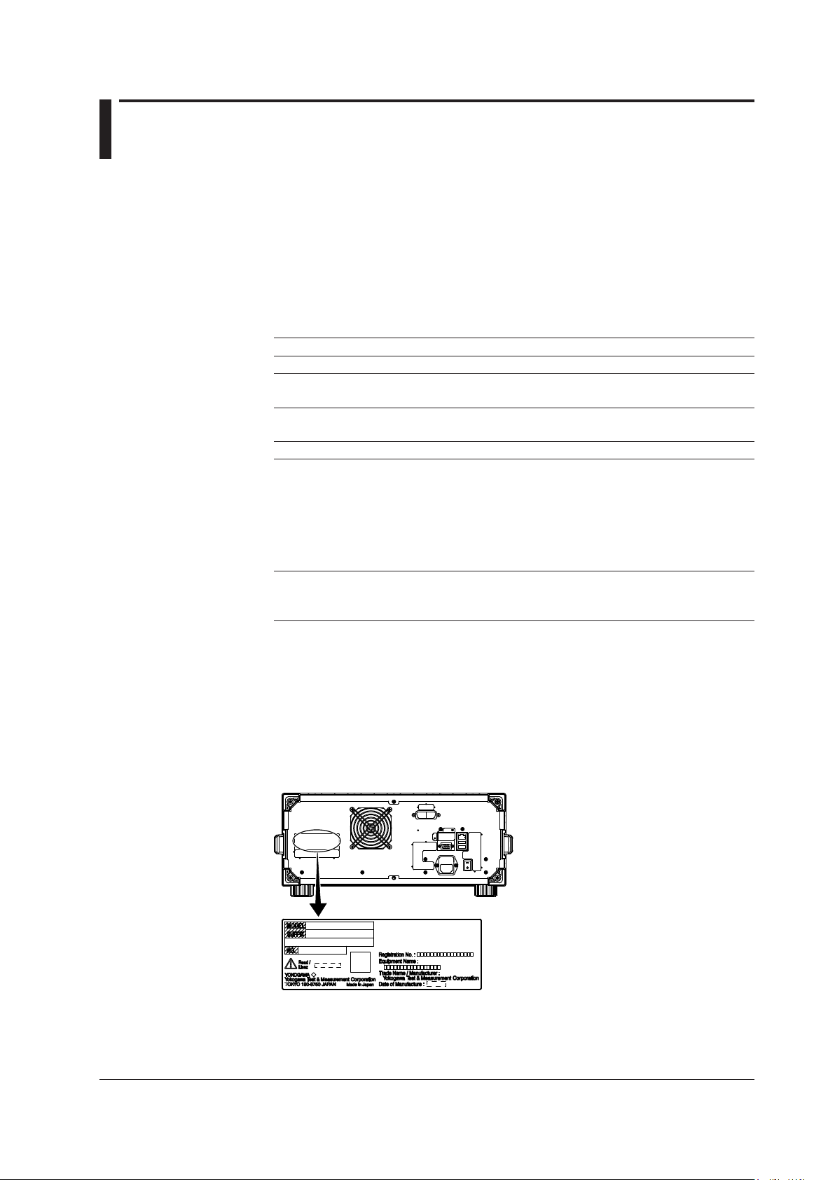
AQ6360 Main Unit
Check that the model and suffix on the name plate on the rear of the instrument
match those of your order. When contacting the dealer from which you purchased the
instrument, please give them the instrument number.
MODEL Suffix Description
AQ6360 AQ6360 Optical Spectrum Analyzer
Spec.Code -10 Standard Model
-01 Limited Model
Optical Connector -FC AQ9447(FC) Connector Adapter
(Optical Input) -SC AQ9447(SC) Connector Adapter
Display -D1 Built-in Display
Power Cord
-F VDE/Korean Standard, Rated Voltage: 250 V
-R Australian Standard, Rated Voltage: 250 V
-Q British Standard, Rated Voltage: 250 V
-H Chinese Standard, Rated Voltage: 250 V
-N Brazilian Standard, Rated Voltage: 250 V
Options
Built-in Light Source /LFC Wavelength Reference Source (FC Connector
/LSC Wavelength Reference Source (SC Connector
1 Already attached to the optical input of the AQ6360 front panel.
2 Make sure that the attached power cord meets the designated standards of the country and
area that you are using it in.
3 Already attached to the calibration light source output of the AQ6360 front panel.
For products whose suffix code contains “Z,” an exclusive manual may be included.
Please read it along with the standard manual.
2
-D UL/CSA Standard and PSE Compliant, Rated
Voltage: 125 V
1
1
3
)
3
)
• No. (Instrument Number)
When contacting the dealer from which you purchased the instrument, please give
them the instrument number.
IM AQ6360-02EN
iii
Page 6

Checking the Contents of the Package
Standard Accessories
Part Name Model or Part No. Quantity Specifications and Notes
Power cord
A1009WD VDE/Korean Standard, Rated Voltage: 250 V
A1024WD Australian Standard, Rated Voltage: 250 V
A1054WD British Standard, Rated Voltage: 250 V
A1064WD Chinese Standard, Rated Voltage: 250 V
A1088WD Brazilian Standard, Rated Voltage: 250 V
Rubber feet A9088ZM 2 1 A9088ZM sheet
Manuals
Printed Manuals IM AQ6360-02EN 1 Getting Started Guide
IM AQ6360-51EN 1 Accompanying the limited model only
IM AQ6360-92Z1 1 Document for China
PIM 113-01Z2 1 List of worldwide contacts
Manual CD A1025US 1 Contains PDFs of the user’s manuals (For
Standard accessories are not covered by warranty of this instrument.
1 Make sure that the attached power cord meets the designated standards of the country and
1
A1006WD 1 UL/CSA Standard and PSE Compliant,
area that you are using it in.
Optional Accessories (Sold Separately)
Part Name Model/Part Number Specifications
AQ9447 connector adapter 810804602-FCC FC type (for optical input)
810804602-SCC SC type (for optical input)
AQ9441 universal adapter 813917321-FCC FC type (for calibration light source output)
813917321-SCC SC type (for calibration light source output)
Optional accessories (sold separately) are not covered by warranty of this instrument.
Rated Voltage: 125 V
the types of manuals that CD contains,
see Manual CD below.)
Manual CD
The English directory in the manual CD contains the PDF files shown below. The CD
also contains Japanese manuals.
File Name Manual Title Manual No.
IMAQ6360-01EN AQ6360 Optical Spectrum Analyzer
User’s Manual
IMAQ6360-17EN AQ6360
Optical Spectrum Analyzer
Remote Control User’s Manual
IM AQ6360-01EN
IM AQ6360-17EN
To view the PDF files above, you need Adobe Reader.
iv
IM AQ6360-02EN
Page 7

Conventions Used in This Manual
Safety Markings
The following markings are used in this manual.
Improper handling or use can lead to injury to the user or damage
to the instrument. This symbol appears on the instrument to indicate
that the user must refer to the user’s manual for special instructions.
The same symbol appears in the corresponding place in the user’s
manual to identify those instructions. In the manual, the symbol is
used in conjunction with the word “WARNING” or “CAUTION.”
WARNING
CAUTION
Calls attention to actions or conditions that could cause serious or
fatal injury to the user, and precautions that can be taken to prevent
such occurrences.
Calls attentions to actions or conditions that could cause light injury to
the user or damage to the instrument or user’s data, and precautions
that can be taken to prevent such occurrences.
French
AVERTISSEMENT
ATTENTION
Calls attention to information that is important for proper operation of
Note
Attire l’attention sur des gestes ou des conditions
Attire l’attention sur des gestes ou des conditions
susceptibles de provoquer des blessures graves (voire
mortelles), et sur les précautions de sécurité pouvant
prévenir de tels accidents.
susceptibles de provoquer des blessures légères ou
d’endommager l’instrument ou les données de l’utilisateur,
et sur les précautions de sécurité susceptibles de prévenir
de tels accidents.
the instrument.
IM AQ6360-02EN
v
Page 8

Conventions Used in This Manual
Notations Used on Pages Describing Operating Procedures
On pages that describe the operating procedures, the following notations are used to
distinguish the procedures from their explanations.
Unit
Procedure
Explanation
This subsection contains the operating procedure used to carry out
the function described in the current chapter. The procedures are
written with inexperienced users in mind; experienced users may not
need to carry out all the steps.
This subsection describes the setup parameters and the limitations
on the procedures.
Characters and Terminology Used in Procedural Explanations
Bold alphanumeric characters in procedural explanations indicate characters appearing near
panel controls and characters of the control menu items shown on the screen.
k: Denotes “1000.” Example: 100 kS/s
K: Denotes “1024.” Example: 459 KB (file data size)
vi
IM AQ6360-02EN
Page 9
Safety Precautions
This product is designed to be used by a person with specialized knowledge.
This instrument is an IEC protection class I instrument (provided with terminal for
protective earth grounding).
The general safety precautions described herein must be observed during all phases
of operation. If the instrument is used in a manner not specified in this manual, the
protection provided by the instrument may be impaired.
This manual is an essential part of the product; keep it in a safe place for future
reference. YOKOGAWA assumes no liability for the customer’s failure to comply with
these requirements.
The following symbols are used on this instrument.
Warning: handle with care. Refer to the user’s manual or service manual.
This symbol appears on dangerous locations on the instrument which require
special instructions for proper handling or use. The same symbol appears in the
corresponding place in the manual to identify those instructions.
Alternating current
ON(power)
OFF(power)
French
Avertissement : À manipuler délicatement.
Toujours se reporter aux manuels d’utilisation et d’entretien. Ce symbole a été
apposé aux endroits dangereux de l’instrument pour lesquels des consignes
spéciales d’utilisation ou de manipulation ont été émises. Le même symbole
apparaît à l’endroit correspondant du manuel pour identifier les consignes qui s’y
rapportent.
Courant alternatif
Marche (alimentation)
Arrêt (alimentation)
IM AQ6360-02EN
vii
Page 10

Safety Precautions
Failure to comply with the precautions below could lead to injury or death or
damage to the instrument.
WARNING
Use the Instrument Only for Its Intended Purpose
The optical measuring instrument is designed to measure the optical characteristics
of light sources and evaluate their performance. Do not use this instrument for
anything other than as an optical measuring instrument.
Check the Physical Appearance
Do not use the instrument if there is a problem with its physical appearance.
Use the Correct Power Supply
Before connecting the power cord, ensure that the source voltage matches the
rated supply voltage of the instrument and that it is within the maximum rated
voltage of the provided power cord.
Use the Correct Power Cord and Plug
To prevent the possibility of electric shock or fire, be sure to use the power cord
supplied by YOKOGAWA. The main power plug must be plugged into an outlet with
a protective earth terminal. Do not disable this protection by using an extension
cord without protective earth grounding.
Also, do not use the power cord that came with the instrument on any other device.
Connect the Protective Grounding Terminal
Make sure to connect the protective earth to prevent electric shock before turning
ON the power. The power cord that comes with the instrument is a three-prong type
power cord. Connect the power cord to a properly grounded three-prong outlet.
Do not Impair the Protective Grounding
Never cut off the internal or external protective earth wire or disconnect the wiring
of the protective earth terminal. Doing so poses a potential shock hazerd.
Do Not Use When the Protection Functions Are Defective
Before using this instrument, check that the protection functions, such as the
protective grounding and fuse, are working properly. If you suspect a defect, do not
use the instrument.
Reference light source output light (/LFC, /LSC option)
The instrument has a built-in reference light source for wavelength calibration, and
infrared light is always being output from the optical output connector. Never look
into the optical output connector. Infrared light entering the eyes can cause severe
injury and loss of vision.
Do not Operate in an Explosive Atmosphere
Do not operate the instrument in the presence of flammable liquids or vapors.
Operation in such environments constitutes a safety hazard.
Do not Remove the Covers or Disassemble or Alter the Instrument
Only qualified YOKOGAWA personnel may remove the covers and disassemble or
alter the instrument.
Opening the cover is dangerous, because some areas inside the instrument have
high voltages.
viii
IM AQ6360-02EN
Page 11

Installation Location
• This instrument is designed to be used indoors. Do not install or use it outdoors.
• Install the instrument so that you can immediately remove the power cord if an
abnormal or dangerous condition occurs.
Manual CD
• Never play this manual CD, which contains the user’s manuals, in an audio CD
player. Doing so may cause loss of hearing or speaker damage due to the large
sounds that may be produced.
CAUTION
Operating Environment Limitations
This product is a Class A (for industrial environment) product. Operation of this
product in a residential area may cause radio interference in which case the user is
required to correct the interference.
French
AVERTISSEMENT
Safety Precautions
Utiliser l’instrument aux seules fins prévues
Cet instrument de mesure optique est prévu pour mesurer les caractéristiques
optiques des sources lumineuses et évaluer leur performance. Ne pas utiliser cet
instrument à d’autres fins que celles de mesure optique.
Inspecter l’apparence physique
Ne pas utiliser l’instrument si son intégrité physique semble être compromise.
Vérifier l’alimentation
Avant de brancher le cordon d’alimentation, vérifier que la tension source
correspond à la tension d’alimentation nominale du AQ6360 et qu’elle est
compatible avec la tension nominale maximale du cordon d’alimentation.
Utiliser le cordon d’alimentation et la fiche adaptés
Pour éviter tout risque de choc électrique ou d’incendie, toujours utiliser le cordon
d’alimentation fourni par YOKOGAWA. La fiche doit être branchée sur une prise
secteur raccordée à la terre. En cas d’utilisation d’une rallonge, celle-ci doit être
impérativement reliée à la terre. Ne pas utiliser le cordon d’alimentation fourni avec
l’instrument pour tout autre appareil.
Brancher la prise de terre
Avant de mettre l’instrument sous tension, penser à brancher la prise de terre pour
éviter tout choc électrique. Le cordon d’alimentation livré avec l’instrument est doté
de trois broches.
Brancher le cordon d’alimentation sur une prise de courant à trois plots et mise à la
terre.
IM AQ6360-02EN
Ne pas entraver la mise à la terre de protection
Ne jamais neutraliser le fil de terre interne ou externe, ni débrancher la borne
de mise à la terre. Cela pourrait entraîner un choc électrique ou endommager
l’instrument.
ix
Page 12

Safety Precautions
Ne pas utiliser lorsque les fonctions de protection sont défectueuses
Avant d’utiliser l’instrument, vérifier que les fonctions de protection, telles que
le raccordement à la terre et le fusible, fonctionnent correctement. En cas de
dysfonctionnement possible, ne pas utiliser l’instrument.
Source de lumière de référence (/LFC, /LSC option)
Cet instrument dispose d’une source de lumière de référence intégrée pour les
ajustements d’alignement. La lumière infrarouge est toujours émise depuis le
connecteur de sortie optique. Ne regardez jamais directement dans le connecteur
de sortie optique. La lumière infrarouge risquerait de gravement vous blesser ou de
provoquer une perte de vision.
Ne pas utiliser dans un environnement explosif
Ne pas utiliser l’instrument en présence de gaz ou de vapeurs inflammables. Cela
pourrait être extrêmement dangereux.
Ne pas retirer le capot, ni démonter ou modifier l’instrument
Seul le personnel YOKOGAWA qualifié est habilité à retirer le capot et à démonter
ou modifier l’instrument. Certains composants à l’intérieur de l’instrument sont à
haute tension et par conséquent, représentent un danger.
Installer et utiliser l’instrument aux emplacements appropriés
• Ne pas installer, ni utiliser l’instrument à l’extérieur ou dans des lieux exposés à
la pluie ou à l’eau.
• Installer l’instrument de manière à pourvoir immédiatement le débrancher du
secteur en cas de fonctionnement anormal ou dangereux.
Manuel CD
• Ce CD contient les manuels d’utilisation. Ne jamais insérer ce CD dans
un lecteur de CD audio. Cela pourrait entraîner une perte d’audition ou
l’endommagement des enceintes en raison du volume potentiellement élevé des
sons produits.
ATTENTION
Limitations relatives à l’environnement opérationnel
Ce produit est un produit de classe A (pour environnements industriels). L’utilisation
de ce produit dans un zone résidentielle peut entraîner une interférence radio que
l’utilisateur sera tenu de rectifier.
x
IM AQ6360-02EN
Page 13
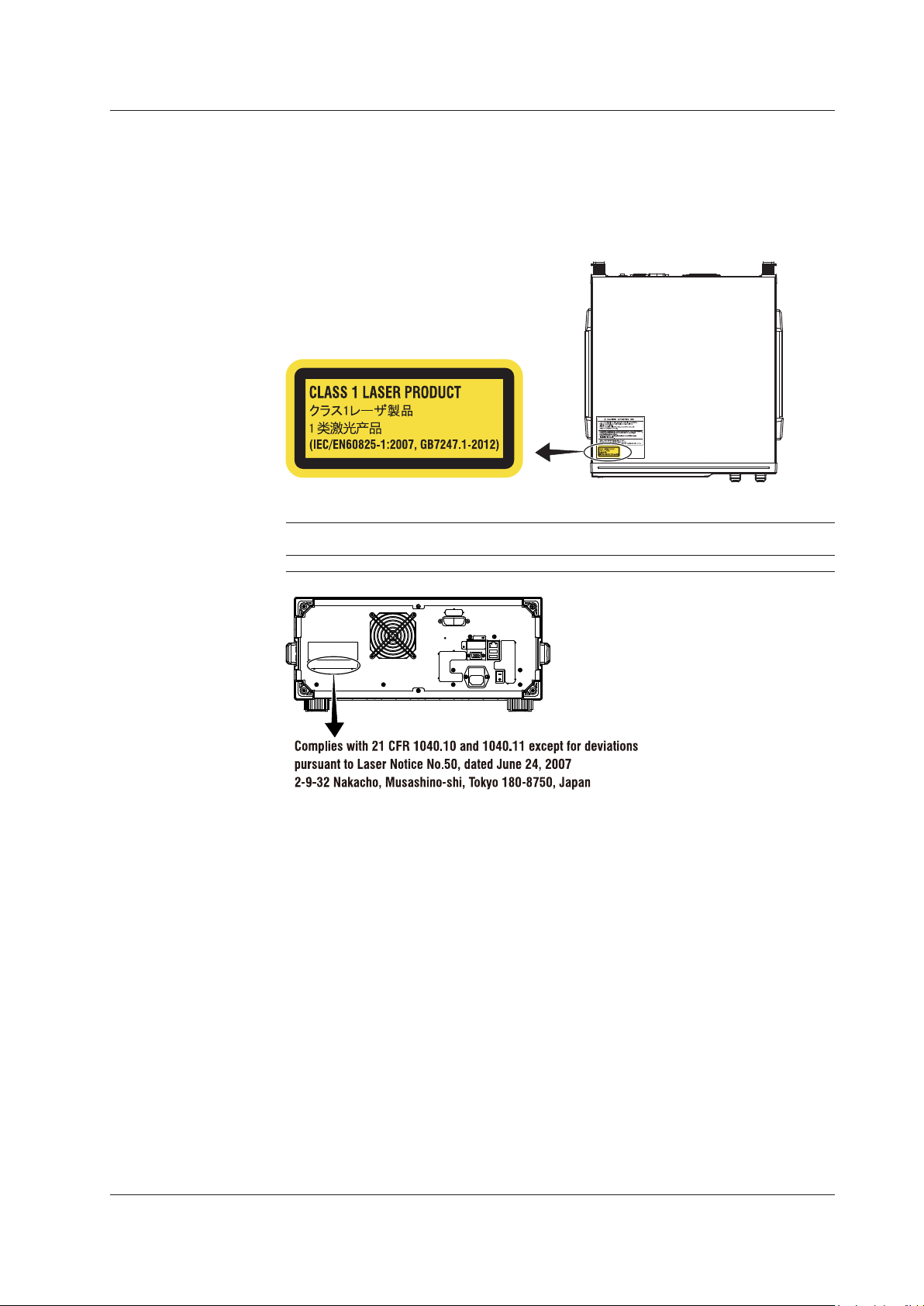
Safety Precautions for Laser Products (/LFC, /LSC option)
This instrument uses a laser light source. This instrument is a Class 1 laser product
as defined by IEC/EN 60825-1:2007 Safety of Laser Products-Part 1: Equipment
Classification, Requirements and User’s Guide. In addition, this instrument complies with
21 CFR 1040.10 and 1040.11 except for deviations pursuant to Laser Notice No. 50,
dated June 24, 2007.
Laser Class 1 Label
Information about the Laser Light Source Used
Class Laser Type Wavelength Maximum
Output Power
1 EE-LED 1.53 µm 0.04 mW 9 µm CW 0.1
Diameter of
Mode Field
Safety Precautions
Repetation
Rate
Numerical
Aperture
IM AQ6360-02EN
xi
Page 14
Regulations and Sales in Each Country or Region
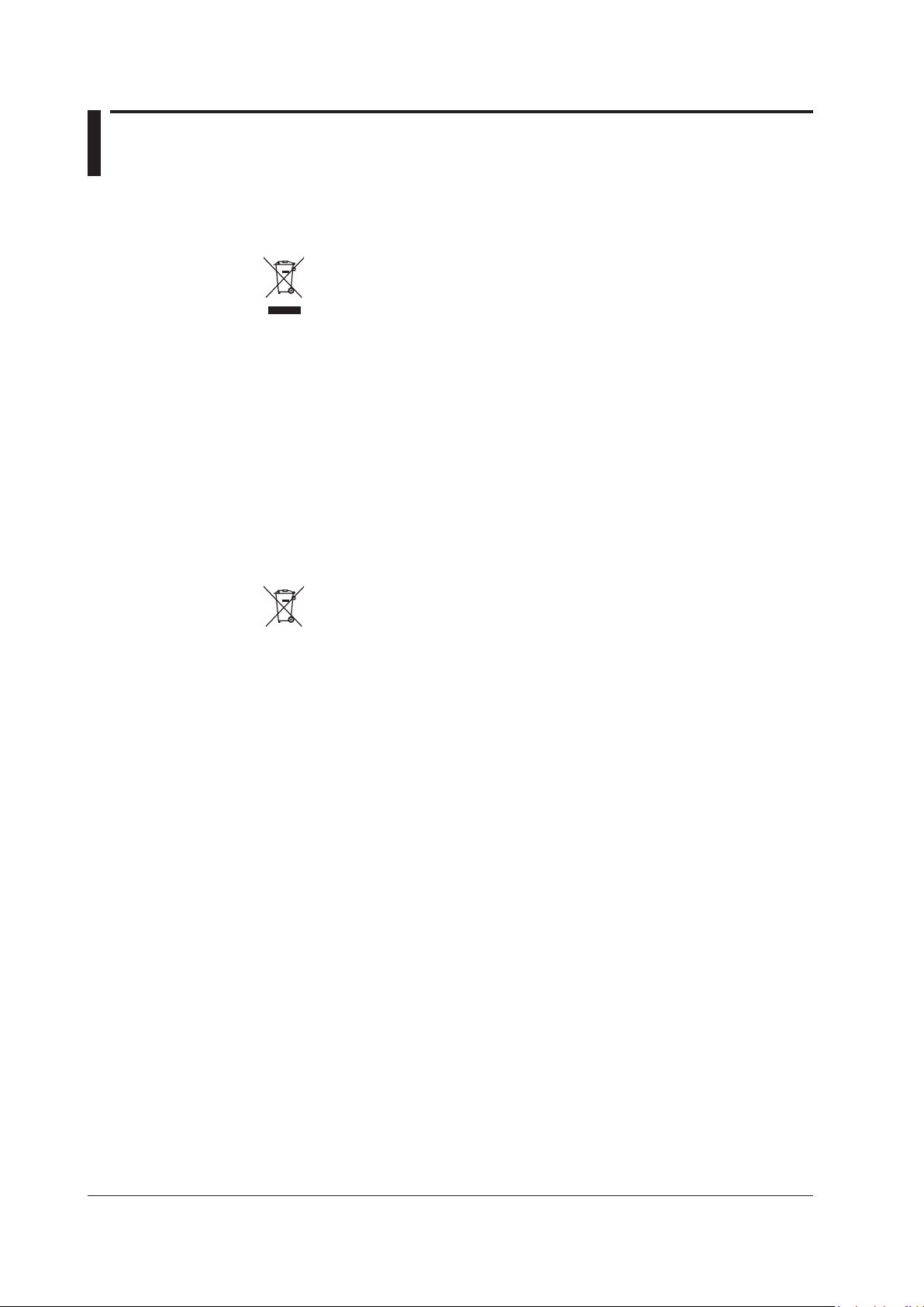
Waste Electrical and Electronic Equipment
Waste Electrical and Electronic Equipment (WEEE)
(This directive is valid only in the EU.)
This product complies with the WEEE Directive marking requirement. This
marking indicates that you must not discard this electrical/electronic product in
domestic household waste.
Product Category
With reference to the equipment types in the WEEE directive, this product is
classified as a “Monitoring and control instruments” product.
When disposing of products in the EU, contact your local Yokogawa Europe B.V.
office. Do not dispose in domestic household waste.
EU Battery Directive
EU Battery Directive
(This directive is valid only in the EU.)
Batteries are included in this product. This marking indicates they shall be sorted
out and collected as ordained in the EU battery directive.
Battery type: Lithium battery
You cannot replace batteries by yourself. When you need to replace batteries,
contact your local Yokogawa Europe B.V. office.
Authorized Representative in the EEA
Yokogawa Europe B.V. is the authorized representative of Yokogawa Test &
Measurement Corporation for this product in the EEA. To contact Yokogawa Europe B.V.,
see the separate list of worldwide contacts, PIM 113-01Z2.
xii
IM AQ6360-02EN
Page 15
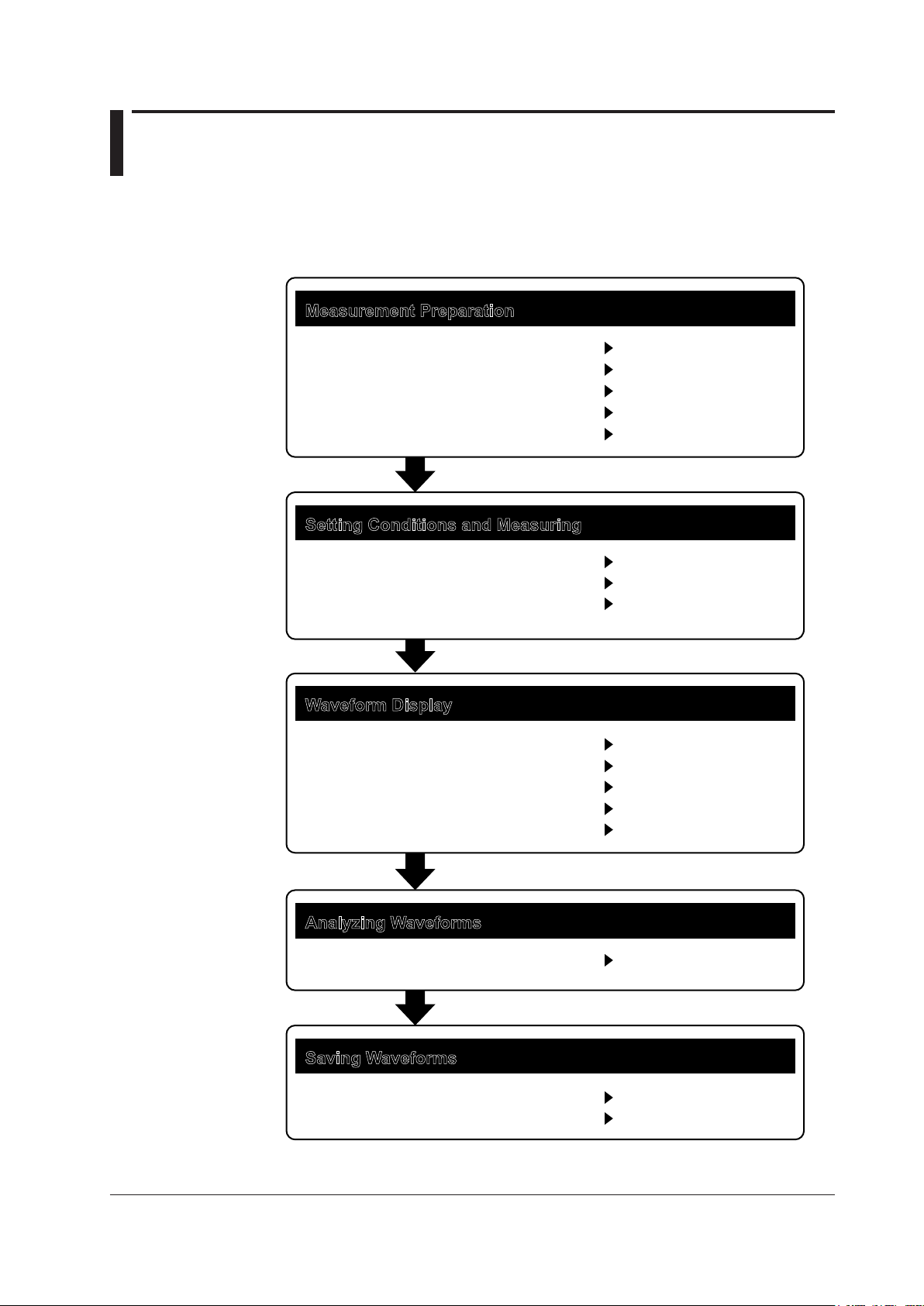
Flow of Operation
* IM AQ6360-01EN
The figure below is provided to familarize the first-time user with the general flow of this
instrument operation. For the details of each item, see the relevant section in IM AQ636001EN or IM AQ6360-02EN.
Measurement Preparation
Installing the Instrument
Turning the Power On and Off
Connecting the DUT
Wavelength Calibration
Resolution Calibration
Setting Conditions and Measuring
Auto Sweep Setting and Measurement
Other Settings
Starting a Measurement (Sweep)
Waveform Display
Displaying Waveforms
Displaying Calculated Waveforms
Displaying Power Spectral Density
Displaying Markers
Searching
Section 2.1
Section 2.4
Section 2.5
Section 2.1*
Section 2.2*
Section 3.1*
Sections 3.2* to 3.12*
Section 3.13*
Sections 4.1* to 4.4*
Section 4.5*
Section 4.8*
Section 4.9*
Sections 4.13* and 4.14*
IM AQ6360-02EN
Analyzing Waveforms
Waveform Analysis
Saving Waveforms
Storage Device
Saving Data
Sections 5.1* to 5.9*
Section 6.1*
Sections 6.2* to 6.7*
xiii
Page 16

xiv
IM AQ6360-02EN
Page 17
Contents
1
List of Manuals ...................................................................................................................................i
Checking the Contents of the Package............................................................................................ iii
Conventions Used in This Manual ....................................................................................................v
Safety Precautions .......................................................................................................................... vii
Regulations and Sales in Each Country or Region ......................................................................... xii
Flow of Operation........................................................................................................................... xiii
Chapter 1 Part Names and Functions
1.1 Front Panel ....................................................................................................................... 1-1
1.2 Rear Panel ....................................................................................................................... 1-2
1.3 LCD Screen ...................................................................................................................... 1-3
Chapter 2 Preparing for Measurement
2.1 Installing the Instrument ................................................................................................... 2-1
2.2 Attaching the Connector Adapter ..................................................................................... 2-5
2.3 Connecting the Device ..................................................................................................... 2-8
2.4 Turning the Power ON/OFF ............................................................................................ 2-10
2.5 Connecting the DUT ....................................................................................................... 2-17
Chapter 3 Common Operations
3.1 Touch Panel Operations ................................................................................................... 3-1
3.2 Menu Operations .............................................................................................................. 3-4
3.3 Entering Numerical Values and Strings .......................................................................... 3-12
3.4 Using the Mouse and External Keyboard ....................................................................... 3-14
3.5 Setting the Date and Time .............................................................................................. 3-16
2
3
4
5
App
Chapter 4 Maintenance
4.1 Updating the Firmware ..................................................................................................... 4-1
4.2 Mechanical Inspection ...................................................................................................... 4-4
4.3 Inspection of Wavelength Accuracy .................................................................................. 4-5
4.4 Inspection of Level Accuracy ............................................................................................ 4-6
4.5 Replacing Fuses ............................................................................................................... 4-7
4.6 Daily Maintenance ............................................................................................................ 4-8
4.7 Care during Storage ........................................................................................................4-11
4.8 Recommended Replacement Parts ............................................................................... 4-12
4.9 Disposal .......................................................................................................................... 4-13
4.10 Warning Display Function ............................................................................................... 4-14
Chapter 5 Specications
5.1 Specications ................................................................................................................... 5-1
5.2 External Dimensions ........................................................................................................ 5-4
Appendix
Appendix 1 MICROSOFT SOFTWARE LICENSE TERMS ...................................................App-1
IM AQ6360-02EN
xv
Page 18
1
2
3 4 5
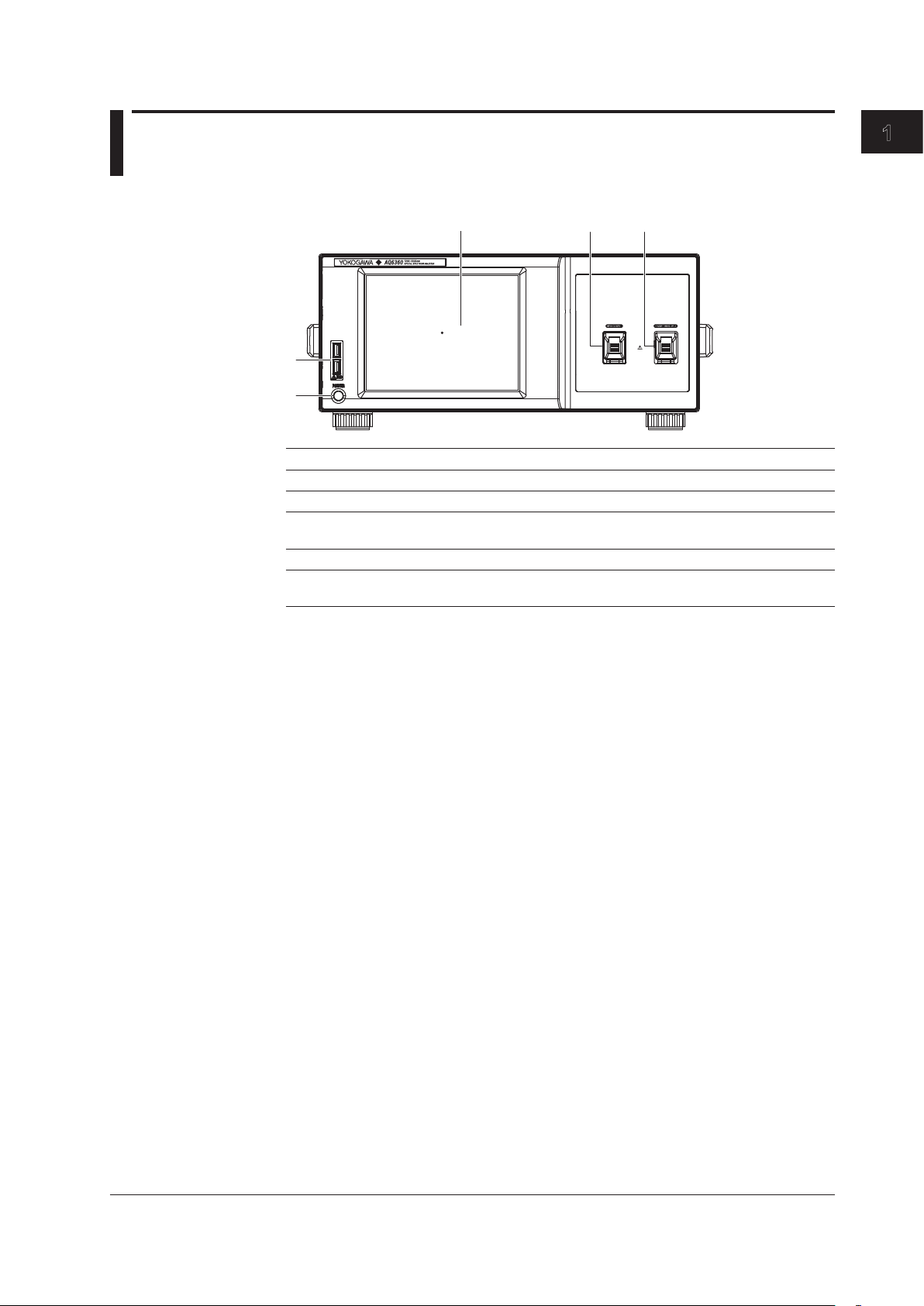
Chapter 1 Part Names and Functions
1.1 Front Panel
No. Name Function
1 POWER Used to start and shut down the instrument.
2 USB interface Used to connect USB storage media
3 LCD display Displays measured waveform, measurement conditions,
4 OPTICAL INPUT Optical input connector
5 CALIBRATION OUTPUT An optical output connector for the reference light source
1
Part Names and Functions
measurement values, etc.
used in wavelength calibration (/LFC, /LSC option)
IM AQ6360-02EN
1-1
Page 19
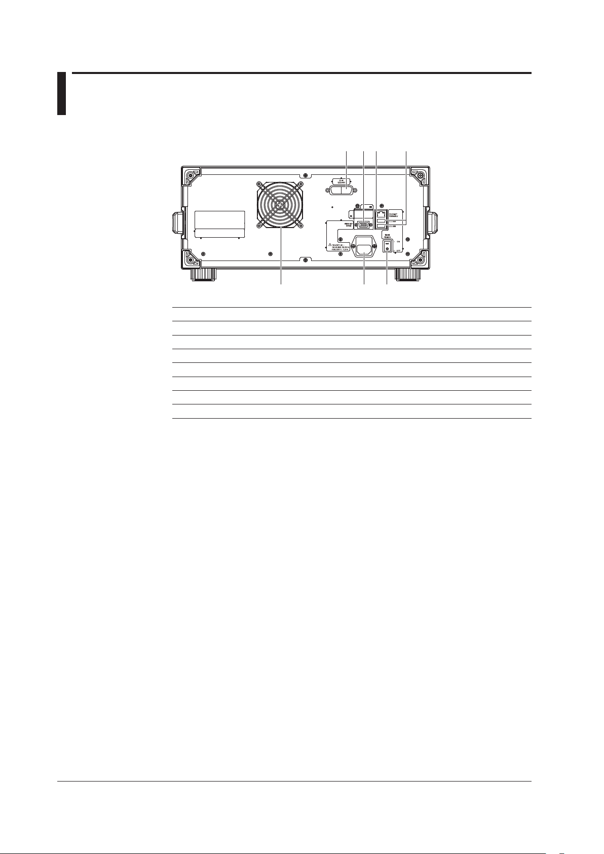
1.2 Rear Panel
1 2 3 4
56
7
No. Name Function
1 GP-IB A GP-IB port for controlling the instrument from a PC
2 VIDEO OUT (SVGA) Analog RGB video signal (SVGA-compliant) interface
3 ETHERNET Ethernet Interface
4 USB interface Used to connect USB storage media or USB mouse
5 MAIN POWER Used to turn the main power ON/OFF
6 Power cord connector Connect the power cord to this connector
7 Exhaust holes Keeps the internal temperature from rising
1-2
IM AQ6360-02EN
Page 20
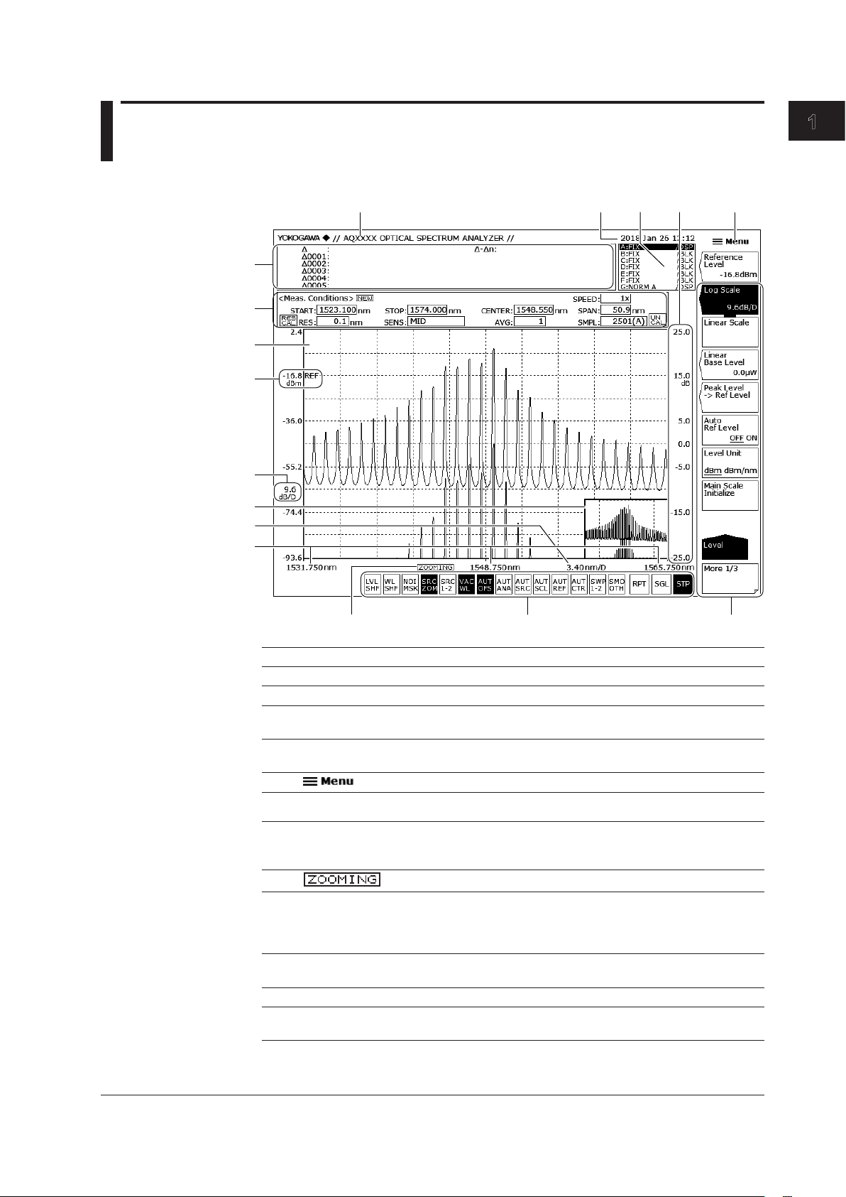
1.3 LCD Screen
1 2 3 5
78
10
11
12
13
14
15
16
6
4
1
Part Names and Functions
9
No. Name Function See
1 Label area Up to 56 characters Section 3.3
2 Year, month, day, time Section 3.5
3 Trace setting area Displays the status of each trace. Tap to display the
setup screen.
4 Subscale Displays relative levels of differential waveforms
5
6 Function menu For configuring various settings. Section 3.2
7 Shortcut keys Shortcuts to frequently used settings. You can
8
9 Wavelength/frequency Displays the start wavelength (frequency), center
10 Wavelength axis scale Displays the wavelength axis scale per division.
11 Overview screen Appears only when the zoom feature is in use. Section 4.1*
12 Level axis scale Displays the level axis scale per division.
and normalized waveforms.
Displays the Main Menu window. Section 3.2
quickly specify settings by simply tapping them.
When a setting is on, the shortcut key is highlighted.
Appears when the zoom feature is in use. Section 4.1*
wavelength (frequency), and stop wavelength
(frequency) of the zoom function.
You can set them directly by tapping the values.
You can set it directly by tapping the value.
You can set it directly by tapping the value.
Section 3.12*,
Chapter 4*
Section 3.3*
Section 3.2
Section 4.1*
Section 4.1*
Section 3.2*
IM AQ6360-02EN
1-3
Page 21
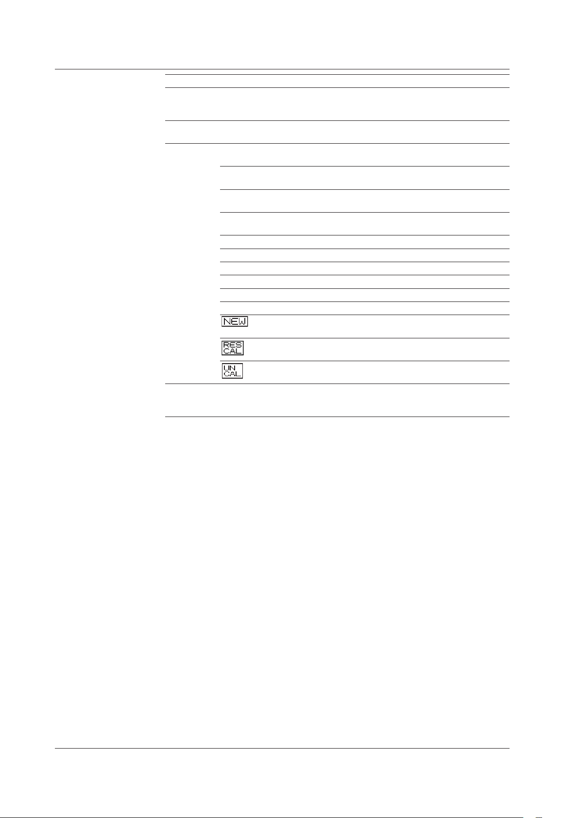
1.3 LCD Screen
No. Name Function See
13 Reference level Displays the reference level. You can change the
vertical display position of the reference level.
You can set it directly by tapping the value.
14 Waveform display area Displays waveforms. Waveforms can be zoomed
using touch panel operation.
15 Measurement
conditions area
START Displays and sets the start wavelength or start
STOP Displays and sets the stop wavelength or stop
CENTER Displays and sets the center wavelength or center
SPAN Displays and sets the sweep span Section 3.6*
SPEED Displays and sets the sweep speed Section 3.10*
RES Displays and sets the resolution Section 3.7*
SENSE Displays and sets the measurement sensitivity Section 3.9*
AVG Displays and sets the average count Section 3.11*
SMPL Displays and sets the sample count Section 3.8*
16 Data area Displays marker values and analysis results. If there
You can set a parameter directly by tapping within
the frame of the value.
frequency
frequency
frequency
Appears when measurement conditions are
changed.
Appears when a resolution calibration has been
performed.
Displayed when the span, sample count, or
resolution setting is inappropriate.
are five or more data values, you can drag the data
area to scroll.
Section 3.4*
Section 3.1,
Chapter 4*
Section 3.2
Section 3.5*
Section 3.5*
Section 3.5*
Chapter 3*
Section 2.2*
Section 3.7*
Chapter 4*,
Chapter 5*
* See the relevant chapter or section in IM AQ6360-01EN.
For details on touch panel operation and menu operation, see chapter 3, “Common
Operations.”
1-4
IM AQ6360-02EN
Page 22

1
Chapter 2 Preparing for Measurement
2.1 Installing the Instrument
WARNING
• This instrument is designed to be used indoors. Do not install or use it outdoors.
• Install the instrument so that you can immediately remove the power cord if an
abnormal or dangerous condition occurs.
• This instrument has a built-in reference light source for wavelength calibration (/
LFC, /LSC option) and transmits infrared light from the optical output connector
at all times. Never look into the optical output connector. Infrared light entering
the eyes can cause severe injury and loss of vision.
CAUTION
Do Not Apply Shock to the Instrument
Non-horizontal orientation, and do not drop the instrument from a height of 2 cm
or more. This can adversely affect the accuracy of the internal monochromator
and inhibit performance. Take great care when transporting the instrument, and
use packaging with a shock absorbing capacity that is greater than or equal to the
packaging used upon shipment from the factory.
Never use inferior packaging materials that are unable to sufficiently absorb
vibrations and shocks occurring during transport. This can adversely affect the
accuracy of the internal monochromator and inhibit performance.
2
Preparing for Measurement
When unpacking
When the instrument is packaged in a box and moved, prevent condensation by
allowing sufficient time for the instrument to acclimatize before removing it from the
box.
French
AVERTISSEMENT
• L’instrument est prévu pour une utilisation en intérieur. Ne pas l’installer, ni l’utiliser
à l’extérieur.
• Installer l’instrument de manière à pourvoir immédiatement le débrancher du
secteur en cas de fonctionnement anormal ou dangereux.
• Cet instrument dispose d’une source de lumière de référence intégrée pour les
ajustements d’alignement (/LFC, /LSC option). La lumière infrarouge est toujours
émise depuis le connecteur de sortie optique. Ne regardez jamais directement
dans le connecteur de sortie optique. La lumière infrarouge risquerait de
gravement vous blesser ou de provoquer une perte de vision.
IM AQ6360-02EN
2-1
Page 23

2.1 Installing the Instrument
ATTENTION
Ne pas heurter l’instrument
En position non horizontale et ne faites pas chuter l’instrument d’une hauteur de
2 cm ou plus. Cela risquerait d’endommager la précision du monochromateur
interne et les performances de l’instrument.
Transportez l’instrument avec maintes précautions et utilisez un emballage d’une
capacité d’absorption supérieure ou égale à celle de l’emballage utilisé pour la
livraison depuis l’usine.
N’utilisez jamais de matériaux d’emballage de qualité inférieure, incapables
d’absorber correctement les vibrations et les chocs survenant au cours du
transport.
Cela risquerait d’endommager la précision du monochromateur interne et les
performances de l’instrument.
Déballage
Lorsque l’instrument est emballé dans un carton et transporté, évitez toute
condensation en le laissant s’adapter aux conditions environnementales
suffisamment longtemps avant de le retirer du carton.
Installation Conditions
Install the instrument so that the following conditions are met.
Flat Horizontal Location
Place the instrument in a stable location that is flat in all directions. If the instrument is
used in an unstable or angled surface, the accuracy of the internal monochromator can
be compromised.
Location without Vibration
Do not install the instrument in a location subject to vibration. Use in a location that
experiences large vibrations can lead to instability of operation, measurement stopping
before completion, or notable decreases in accuracy of the wavelength and level axes.
Well Ventilated Location
Ventilation holes are present at the sides and rear of the instrument. To keep the
internal temperature from rising, always maintain a gap of 200 mm or more between the
ventilation holes and the installation surfaces.
2-2
IM AQ6360-02EN
Page 24
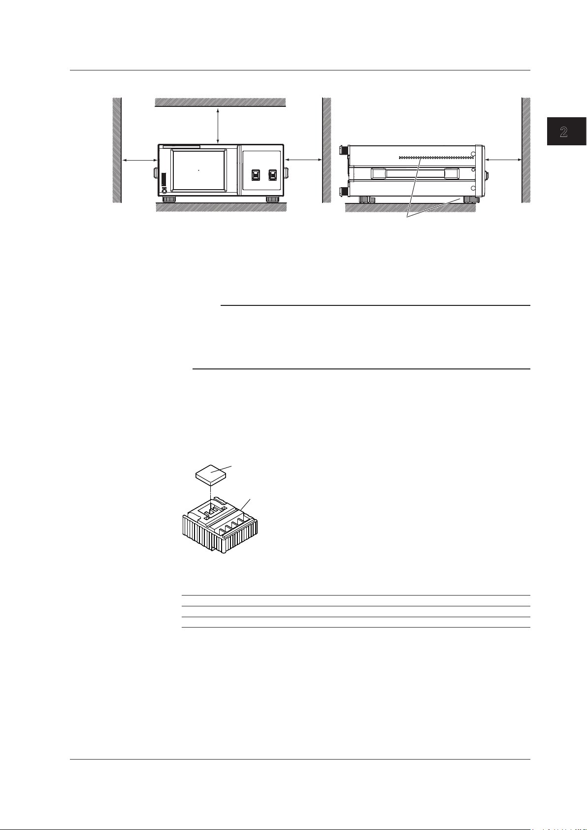
1
Inlet holes (also on the bottom panel)
2.1 Installing the Instrument
Also be sure to maintain sufficient clearance for connecting measurement cables.
20 cm or
more
20 cm or more
20 cm or
more
20 cm or
more
Ambient Temperature and Humidity
Ambient temperature: 5 to 35°C
Ambient humidity: 20%RH to 85%RH (no condensation present)
Note
Condensation may occur if the instrument is moved to another place where the ambient
temperature is higher, or if the temperature changes rapidly. In such cases, allow sufficient time
for the instrument to adjust to the ambient temperature before use.
When the instrument is packaged in a box and moved, prevent condensation by allowing
sufficient time for the instrument to acclimatize before removing it from the box.
Flat, Even Surface
Install the instrument with the correct orientation on a stable, horizontal surface. If the
instrument is installed in a horizontal position, rubber stoppers can be attached to the
feet at the rear of the instrument to prevent the instrument from sliding. One set of rubber
stoppers (two stoppers) are included with the instrument.
2
Preparing for Measurement
Rack Mounting
Rubber stoppers
A9088ZM
Feet at the rear of the instrument
To rack-mount the instrument, use the separately sold rack mount kit.
Product Name Model
Rack Mounting Kit for EIA Single 751535-E4
Rack Mounting Kit for JIS Single 751535-J4
IM AQ6360-02EN
2-3
Page 25
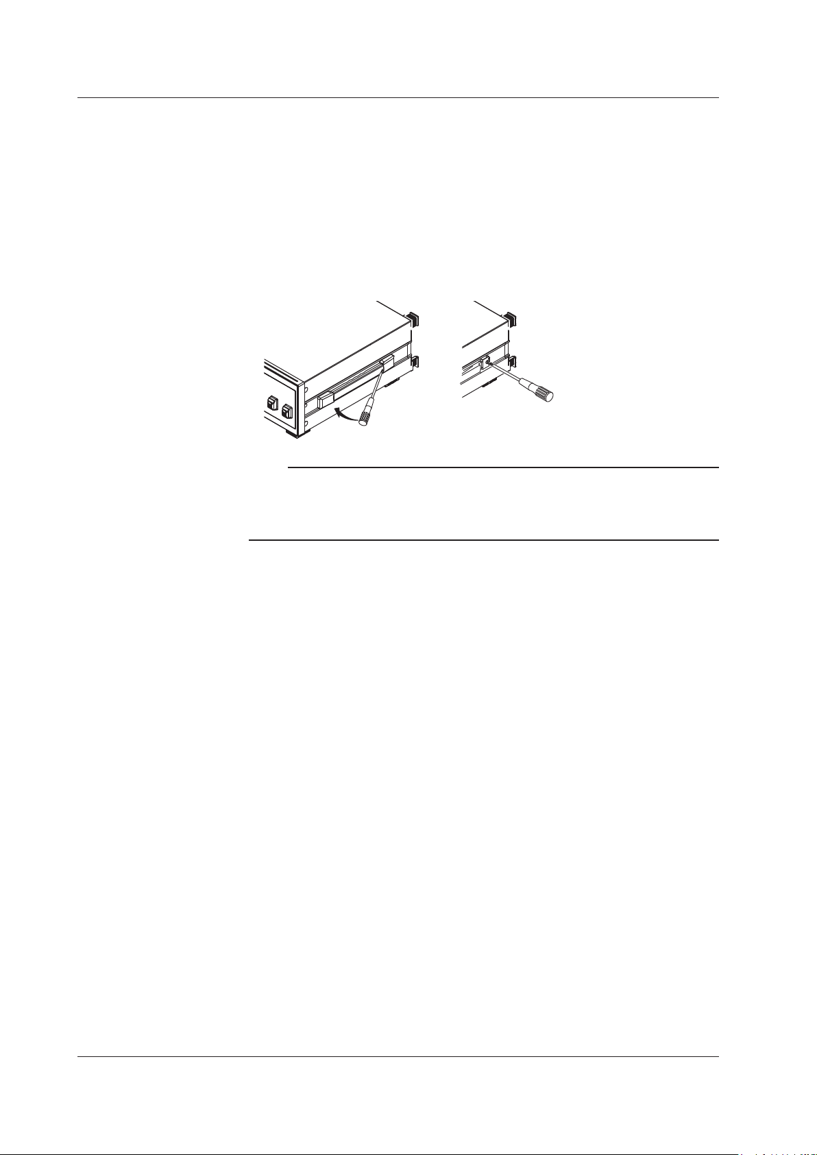
2.1 Installing the Instrument
An outline of the mounting procedure is given below. For detailed instructions, see the
manual that is included with the rack mount kit.
Remove the handles from both sides of the instrument.
1.
Remove the four feet from the bottom of the instrument.
2.
Remove the four seals the rack mount attachment holes on each side of the
3.
instrument near the front.
Place seals over the feet and handle attachment holes.
4.
Attach the rack mount kit to the instrument.
5.
Mount the instrument on a rack.
6.
Note
• When rack-mounting the instrument, allow at least 10 cm of space around the inlet and
exhaust holes to prevent internal heating.
• Make sure to provide adequate support from the bottom of the instrument. The support
should not block the inlet and exhaust holes.
Do Not Install the Instrument in the Following Places
• Outdoors.
• Dangerous locations where flammable or explosive gasses, vapors, or dust is present,
or where the possibility of explosions or fires exists.
• In direct sunlight or near heat sources.
• Where an excessive amount of soot, steam, dust, or corrosive gas is present.
• Location where mechanical vibration is high.
• In an unstable place.
• Where the instrument is exposed to water or other liquids.
General Handling Precautions
• Take Proper Care When Carrying the Instrument
Hold the instrument by the handles on the sides of the case. The instrument weighs
approximately 15.5 kg. Take precautions against injuries when carrying it.
turn the power switch OFF, remove the power cable, and confirm that no other cables
are connected before carrying the instrument.
• Do Not Place Anything on Top of the Instrument
Never stack instruments or place any other objects on top of the instrument, especially
those containing water. Doing so can lead to malfunction.
• Clean the Instrument Properly
When removing dirt from the case or the LCD, disconnect the power to the circuits
under test and the instrument, remove the instrument’s power cord from the power
outlet, then wipe gently with a clean, dry cloth. Do not use volatile chemicals since this
might cause discoloring and deformation.
Also, always
2-4
IM AQ6360-02EN
Page 26
1
2.2 Attaching the Connector Adapter
Attach the optional connector adapter before using the instrument.
WARNING
Always turn the power OFF before replacing the connector adapter. This instrument
has a built-in reference light source for wavelength calibration (/LFC, /LSC option)
and transmits infrared light from the optical output connector at all times. Never
look into the optical output connector. Infrared light entering the eyes can cause
severe injury and loss of vision.
CAUTION
• As there may be dust adhering to calibration output, be sure to clean it before
attaching the connector adapter.
• Do not exhale or blow compressed air into the monochromator from the optical
input. Doing so may allow dust or other materials to enter the monochromator,
adversely affecting its optical performance. Also, if debris is adhering to the
optical components inside the monochromator when a strong light source is
input, the monochromator may be damaged.
• When attaching or removing the connector adapter, carefully insert it
perpendicularly to the ferrule so as not to damage the ferrule end.
• Moving the connector adapter to the right or left or inserting it forcefully can
damage the ferrule or the connector adapter.
2
Preparing for Measurement
French
AVERTISSEMENT
Toujours éteindre l’avant de remplacer l’adaptateur de connecteur.
Cet instrument dispose d’une source de lumière de référence intégrée pour les
ajustements d’alignement (/LFC, /LSC option). La lumière infrarouge est toujours
émise depuis le connecteur de sortie optique. Ne regardez jamais directement
dans le connecteur de sortie optique. La lumière infrarouge risquerait de gravement
vous blesser ou de provoquer une perte de vision.
IM AQ6360-02EN
2-5
Page 27

2.2 Attaching the Connector Adapter
ATTENTION
• Comme il peut y avoir de la poussière adhérant à la sortie d’étalonnage,
assurez-vous de le nettoyer avant de fixer l’adaptateur de connecteur.
• Ne pas expirer ou souffler de l’air comprimé dans le monochromateur de l’entrée
optique. Cela pourrait permettre à la poussière ou d’autres matériaux pour
entrer dans le monochromateur, nuire à ses performances optiques. En outre,
si des débris adhère aux composants optiques à l’intérieur du monochromateur
quand une forte source de lumière est entrée, le monochromateur peut être
endommagé.
• Lors de la fixation ou du retrait de l’adaptateur de connecteur, insérer
soigneusement perpendiculairement à la virole de manière à ne pas
endommager l’extrémité virole.
• Déplacement de l’adaptateur de connecteur vers la droite ou vers la gauche
ou en l’insérant de force peut endommager la virole ou de l’adaptateur de
connecteur.
A connector adapter is required for connecting the optical connector to the AQ6360.
On products whose optical connector (optical input) specification is -FC or -SC and those
with an /LFC or /LSC option, connector adapters come attached to the optical input and
calibration light source output on the instrument’s front panel.
On products without these options, attach a connector adapter appropriate for the optical
connector.
Note
Attachment Procedure
1.
2.
3.
4.
5.
A different connector adapter is used for OPTICAL INPUT and CALIBRATION OUTPUT. Make
sure not to use the wrong connector adapter.
Confirm that the power is OFF.
Open the optical connector cover at the front of the instrument.
Clean the ferrule edge of the optical I/O section using a swab soaked with a small
amount of pure alcohol.
Insert the connector adapter all the way in.
Push the connector adapter’s lock lever down.
The adapter has been attached correctly if the groove in the lock lever interlocks with the
latch pin of the optical input/output section.
2-6
IM AQ6360-02EN
Page 28

1
Removal Procedure
Panel
Optical input
Connector
SC type
SC type
2.2 Attaching the Connector Adapter
Confirm that the power is OFF.
1.
Turn the connector adapter’s lock lever up. The lock lever’s lock is released.
2.
Pull the connector adapter all the way out.
3.
Close the optical connector cover at the front of the instrument.
4.
2
Preparing for Measurement
Explanation
Types of Connector Adapter
The connector adapter for internal reference light output (AQ9441) comes in the following
two types.
FC type
The optical input connector adapter (AQ9447) comes in the following two types.
section
Ferrule
Latch pin
adapter
Lock lever
Attached
Optical Connectors Types
IM AQ6360-02EN
FC type
The instrument can use FC or SC type optical connectors.
Cap
FC type optical
connector
Cap
SC type optical
connector
2-7
Page 29

2.3 Connecting the Device
Connecting the Mouse
You can use a USB or PS/2 mouse.
Supported USB Mouse
The instrument can support a USB HID Class Ver. 1.1 compliant mouse (with wheel).
Connections
Connect a USB mouse to one of the USB interfaces on the front or rear panel of the
instrument.
Confirm that MAIN POWER switch on the rear panel is OFF.
1.
Orient the mouse connector so that it matches the orientation of the interface,
2.
then insert the connector.
Note
• There are 2 USB interfaces each on front and rear panels, but do not connect more than
one mouse at a time.
• In addition to a USB mouse, the USB interfaces can be used to connect USB storage and
keyboards.
For information on operations using the mouse, see section 3.4.
Connecting a Keyboard
You can connect a keyboard for entering file names, comments, and other items. The
instrument features and settings are mapped to the keys on the keyboard, so you
can use the keyboard to perform the same operations that you can perform using the
instrument’s menus.
Supported Keyboards
The instrument supports any 101 English USB keyboard.
Connecting
Connect a USB keyboard to one of the USB interfaces on the front or rear panel of the
instrument.
Confirm that the MAIN POWER switch on the rear panel is OFF.
1.
Orient the mouse connector so that it matches the orientation of the interface,
2.
Note
• There are 2 USB interfaces each on front and rear panels, but do not connect more than
• In addition to a USB keyboard, the USB interfaces can be used to connect USB storage and
then insert the connector.
one keyboard at a time.
a USB mouse.
2-8
For information on operations using the keyboard, see section 3.4.
IM AQ6360-02EN
Page 30

1
Connecting a USB Storage Device
Supported USB Storage Devices
The instrument supports USB memory (USB card adapters).
You cannot use a USB storage device not recognized by the instrument. If the USB
storage device’s drive is partitioned, only the primary partition (F:) is recognized. If there
are two or more USB storage devices, only the first connected device is recognized.
If you restart the instrument, it the USB storage devices that were connected will still be
recognized.
Connections
Connect the USB storage device to the USB connector on the front panel of the
instrument.
2.3 Connecting the Device
2
Preparing for Measurement
Removing
USB connector
See section 6.1 in IM AQ6360-01EN. (You will use the Remove USB Storage function
menu.)
CAUTION
Do not remove the USB storage device or turn the power OFF while the USB
storage device access indicator is blinking. This can damage the data on the device
or the device itself.
French
ATTENTION
Ne retirez pas le dispositif de stockage USB et ne coupez pas l’alimentation
lorsque le voyant d’accès au dispositif de stockage USB clignote. Cela risquerait
d’endommager le dispositif ou les données se trouvant sur ce dernier.
Connecting with Other Devices
The GP-IB interface or Ethernet interface can be used to connect external devices to this
instrument. For details, see the Remote Control User’s Manual, IM AQ6360-17EN.
Note
Before connecting a GP-IB instrument, such as an external computer, or a LCD monitor or
other display to the instrument, check the wiring, and be sure to turn OFF the power to the
instrument and the instruments to be connected first.
Leaving the power ON while making connections can damage the equipment.
IM AQ6360-02EN
2-9
Page 31

2.4 Turning the Power ON/OFF
Before Connecting the Power
Take the following precautions before turning on the power supply. Failure to do so can
result in electric shock or damage to instruments.
WARNING
• Before connecting the power cord, ensure that the power supply source voltage
matches the rated supply voltage of the instrument and that it is within the
maximum rated voltage of the provided power cord.
• Check that the instrument’s power switch is OFF before connecting the power
cord.
• To prevent electric shock or fire, be sure to use the power cord for the instrument
that is supplied by YOKOGAWA.
• Make sure to connect protective earth grounding to prevent electric shock.
Connect the power cord to a three-prong power outlet with a protective earth
terminal.
• Do not use an extension cord without protective earth ground. Otherwise, the
protection function will be compromised.
• If an AC outlet that conforms to the supplied power cord is unavailable and you
cannot ground the instrument, do not use the instrument.
French
AVERTISSEMENT
• Avant de brancher le cordon d’alimentation, vérifiez que la tension de la source
d’alimentation correspond à la tension d’alimentation nominale de l’instrument
et qu’elle est compatible avec la tension nominale maximale du cordon
d’alimentation fourni.
• Vérifiez que l’interrupteur d’alimentation de l’instrument est sur OFF avant de
brancher le cordon d’alimentation.
• Pour éviter tout risque de choc électrique ou d’incendie, utiliser exclusivement le
cordon d’alimentation fourni par YOKOGAWA et prévu pour l’instrument.
• Relier l’instrument à la terre pour éviter tout risque de choc électrique. Brancher
le cordon d’alimentation sur une prise de courant à trois plots reliée à la terre.
• N’utilisez pas de rallonge si celle-ci n’est pas reliée à la terre, car la fonction de
protection serait compromise.
• En l’absence de prise secteur conforme au cordon d’alimentation et dans
l’impossibilité de mettre l’instrument à la terre, ne pas utiliser l’instrument.
2-10
IM AQ6360-02EN
Page 32

1
Preparing to Turn ON the Power
The AQ6360 has a MAIN POWER switch for turning the main power ON/OFF, and a
POWER switch for starting and shutting down the instrument. The POWER switch is a
push-button switch; press once to turn it ON and press again to turn it OFF.
• Confirm that the MAIN POWER switch on the rear panel of the instrument is OFF.
• Connect the power cord plug to the power connector on the rear panel.
• Connect the other end of the cord to an outlet that meets the following conditions. Use
a grounded three-prong outlet.
Item
Rated supply voltage* 100 VAC to 240 VAC
Permitted supply voltage range 90 VAC to 264 VAC
Rated power supply frequency 50/60 Hz
Permitted supply frequency range 48 Hz to 63 Hz
Maximum power consumption Approx. 100 VA
* This instrument can use a 100 V or a 200 V power supply. The maximum rated voltage differs
according to the type of power cord. Before you use the instrument, check that the voltage
supplied to it is less than or equal to the maximum rated voltage of the power cord provided
with it (see page iii for the maximum voltage rating).
CAUTION
2.4 Turning the Power ON/OFF
2
Preparing for Measurement
Do not input a strong light source to the instrument when turning the power ON. If a
strong light source is input, the optical section can be damaged.
French
ATTENTION
Ne retirez pas le dispositif de stockage USB et ne coupez pas l’alimentation
lorsque le voyant d’accès au dispositif de stockage USB clignote. Cela risquerait
d’endommager le dispositif ou les données se trouvant sur ce dernier.
Power On and Screen Display
Connect the power cord to the power cord connector on the back side of the
1.
instrument.
Three-prong outlet
Power cord
(accessory)
IM AQ6360-02EN
2-11
Page 33

2.4 Turning the Power ON/OFF
Turn ON the MAIN POWER switch on the rear panel of the instrument. The
2.
POWER switch on the front panel of the instrument lights orange.
Wait a few seconds after step 2, and then press the POWER switch on the front
3.
panel of the instrument. The color of the switch turns from orange to green. The
operating system starts up, and initialization of the instrument begins.
The instrument will not start for a few seconds immediately after step 2 even if you press the
POWER switch.
The initialization screen appears, and the internal initialization process starts. STEP
1/9 through STEP 9/9 are displayed in the lower right part of the screen to indicate the
progress of initialization.
CAUTION
Do not press the POWER or MAIN POWER switches while initialization is in
progress. Doing so can cause malfunction.
French
ATTENTION
N’appuyez pas sur les interrupteurs POWER ou MAIN POWER pendant
l’initialisation. Cela pourrait provoquer des dysfonctionnements.
2-12
IM AQ6360-02EN
Page 34

1
2.4 Turning the Power ON/OFF
Operations Performed When the power is Turned On
When the initialization finishes successfully, the following measurement screen appears.
Appears only on models
with an /LFC or /LSC
option (with built-in
reference light source).
On models with an /LFC or /LSC option (with built-in reference light source), a message
prompting you to execute wavelength calibration appears. The message that appears is
shown below.
For this instrument to meet its specifications, a Wavelength Calibration must be
performed. Please perform according to the guidelines below.
2
Preparing for Measurement
Wavelength Calibration
Please perform a Wavelength Calibration after a 1-hour warm-up and before
starting a measurement. Unless the Wavelength Calibration is carried out, the
wavelength accuracy of this instrument cannot be guaranteed.
For details on wavelength calibration, see section 2.1 in IM AQ6360-01EN.
When the Power-on Operation Does Not Finish Normally
Turn off the power switch, and check that :
• The instrument is installed properly. See section 2.1, "Installing the Instrument."
• The power cord is connected properly. See the previous page.
If the instrument still does not work properly, contact your nearest YOKOGAWA dealer for
repairs.
If a memory error or other errors occur during initialization, initialization is cancelled at
the step in which the error occurs (STEP @/9, where @ is a number from 1 to 9). Then,
the screen changes to the measurement screen, and a warning message is displayed.
If this occurs, repairs are necessary. Contact your nearest YOKOGAWA dealer
immediately.
Note
The instrument retains the measurement conditions, the function menu state, the waveforms
that it is showing, and so on. When the power is turned ON, the state of the instrument prior to
the last shut down is restored. When the power is turned ON for the first time, the instrument
starts up in the factory default state.
IM AQ6360-02EN
2-13
Page 35

2.4 Turning the Power ON/OFF
Turning the Power OFF
CAUTION
French
ATTENTION
Do not cut the power to the instrument with the MAIN POWER switch on the rear
panel when an operation is in progress. The operating system configuration file will
not be backed up, possibly resulting in malfunctions upon start up the next time the
instrument is turned ON. Be sure to follow the procedure below to shut down the
instrument.
Lorsque l’instrument est en cours de fonctionnement, ne coupez pas son
alimentation à l’aide de l’interrupteur MAIN POWER situé sur le panneau arrière.
Le fichier de configuration du système d’exploitation ne serait pas sauvegardé, ce
qui entraînerait probablement des dysfonctionnements à la prochaine mise sous
tension de l’instrument. Suivez toujours la procédure ci-dessous.
Veiller à suivre la procédure ci-dessous pour arrêter l’instrument.
2-14
IM AQ6360-02EN
Page 36

1
2.4 Turning the Power ON/OFF
Press the POWER switch on the instrument’s front panel. A shutdown confirmation
1.
message appears, and Yes and No keys appear in the function menu.
Tap Yes. The message “AQ6360 is shutting down Please wait.....” appears, and
2.
the shutdown procedure begins.
If you do not want to shut down, tap No. The screen returns to the previous
screen.
After the POWER switch changes from green to orange, turn OFF the MAIN
3.
POWER switch on the rear panel of the instrument.
Shutdown is also possible by selecting SYSTEM from the Main Menu window.
Tap . The Main Menu window appears.
1.
Tap SYSTEM.
2.
Tap More to display the More 4/4 function menu.
3.
Tap Shut Down.
4.
Tap Yes. The shutdown procedure begins.
5.
After the POWER switch changes from green to orange, turn OFF the MAIN
6.
POWER switch on the rear panel of the instrument.
2
Preparing for Measurement
Note
If for some reason the instrument fails to shut down normally, hold down the
for approximately four seconds or longer to force standby mode. Note that the operating system
configuration file will not be backed up, possibly resulting in malfunctions upon start up the next
time the instrument is turned on.
POWER
switch
IM AQ6360-02EN
2-15
Page 37

2.4 Turning the Power ON/OFF
Explanation
Screen when the instrument was not shut down
If the shutdown procedure was not performed after the previous session, the following
message appears after start up.
Function failure may occur if the instrument is not shut down. When turning OFF the
power, always perform the shut down procedure.
Tap the screen to clear this message.
2-16
IM AQ6360-02EN
Page 38

1
2.5 Connecting the DUT
WARNING
Do not look at the optical fiber laser light that you are measuring or point the laser
at another person’s eye. Doing so may cause eye damage or impair one’s health.
CAUTION
• Before connecting an optical fiber to the instrument, make sure that the start-up
initialization process has finished. If a strong light source is input during start-up,
the optical section can be damaged.
• Be sure to clean the tip of the optical fiber’s optical connector before connecting.
• As there may be dust adhering to calibration output, be sure to clean it before
connecting optical fiber.
• Do not try to forcefully attach the optical fiber’s optical connector with the plug
inserted at a slanted angle. Doing so may damage the instrument’s optical
connector’s components or the connector itself.
• Before connecting the input light, make sure that it does not exceed the
AQ6360’s maximum rated level. If input light exceeding the maximum rated level
is introduced, the optical section may be damaged.
• Do not exhale or blow compressed air into the monochromator from the optical
input. Doing so may allow dust or other materials to enter the monochromator,
adversely affecting its optical performance. Also, if debris is adhering to the
optical components inside the monochromator when a strong light source is
input, the monochromator may be damaged.
• Press the optical connector hard against the cleaning surface of the special
cleaner to clean it. If it is not pressed hard against the cleaning surface, it may
not be possible to properly clean the optical connector.
2
Preparing for Measurement
French
AVERTISSEMENT
Ne regardez pas directement la lumière du laser à fibre optique et ne pointez pas
le laser vers le yeux d’une tierce personne, pour ne pas provoquer de blessures ou
de dommages oculaires.
IM AQ6360-02EN
2-17
Page 39

2.5 Connecting the DUT
ATTENTION
• Avant de connecter l’instrument à une fibre optique, vérifiez que la procédure
d’initialisation de démarrage est terminée. Si vous connectez une source de
lumière puissante au démarrage, la section optique risque d’être endommagée.
• Veillez à nettoyer l’extrémité du connecteur de la fibre optique avant le
raccordement.
• Comme il peut y avoir de la poussière adhérant à la sortie d’étalonnage,
assurez-vous de le nettoyer avant de fixer l’adaptateur de connecteur.
• Ne forcez pas le connecteur de la fibre optique dans la fiche en l’insérant de
manière inclinée. Vous risqueriez de l’endommager ou d’endommager ses
composants.
• Avant de connecter la lumière d’entrée, vérifiez qu’elle ne dépasse la valeur
nominale maximale de l’analyseur AQ6370D, car si tel était le cas, la section
optique pourrait être endommagée.
• Ne pas expirer ou souffler de l’air comprimé dans le monochromateur de l’entrée
optique. Cela pourrait permettre à la poussière ou d’autres matériaux pour
entrer dans le monochromateur, nuire à ses performances optiques. En outre,
si des débris adhère aux composants optiques à l’intérieur du monochromateur
quand une forte source de lumière est entrée, le monochromateur peut être
endommagé.
• Appuyez fermement le connecteur optique sur la surface nettoyante du
nettoyeur. Si vous n’appuyez pas fermement, le connecteur optique risque de ne
pas être correctement nettoyé.
Cleaning the Optical Fiber End Face
Firmly press the connector end face of the optical fiber against the cleaning
1.
While pressing the end face against the cleaner, turn it once.
2.
While pressing the end face against the cleaner, move it.
3.
Repeat steps 1 to 3.
4.
Note
• If you do not firmly press the connector end face of the optical fiber against the cleaner, the
• You can purchase an optical fiber connector cleaner from NTT-AT Corporation.
surface of the cleaner.
end face may not be cleaned completely.
2-18
IM AQ6360-02EN
Page 40

1
Connecting Optical Fibers
Light source
Optical fiber
Open the instrument’s optical input connector cover.
5.
Connect the optical fiber’s optical connector to the optical input connector on the
6.
instrument.
Setting the optical fiber connector
Tap . The Main Menu window appears.
7.
Tap SETUP. The function menu appears.
8.
Tap More 1/2.
9.
Tap Fiber Connector. NORM and ANGLED toggles each time you tap the menu.
10.
Set ANGLED if the optical fiber under test is APC (angle lap PC). Otherwise, set
NORM.
Note
• If you set Fiber Connector to ANGLED, is displayed in the measurement
conditions area.
• The instrument's measurement accuracy specification is for when Fiber Connector is set to
NORM.
2.5 Connecting the DUT
2
Preparing for Measurement
Connecting the DUT (Light Source)
Clean the top of the optical connector on the other end of the optical fiber with a
11.
Connect the optical connector on the other end of the optical fiber to the optical
12.
Measuring System
Explanation
Optical Connectors Types
The instrument can use FC or SC type optical connectors.
fiber cleaner.
connector on the DUT.
AQ6360
IM AQ6360-02EN
Cap
FC type optical
connector
Cap
SC type optical
connector
2-19
Page 41

1
2
Pinch out Pinch in
Chapter 3 Common Operations
3.1 Touch Panel Operations
Basic Touch Panel Operations
The basic touch panel operations are described below.
Tap
Tap refers to the act of gently hitting the screen with your finger.
This is used to select a menu, enter data, and so on.
Drag
Drag refers to the act of pressing your finger against the screen and sliding your finger.
This is used to move the displayed waveform or marker position.
Pinch Out and Pinch In
Pinch out refers to the act of pressing two fingers against the screen and spreading them
apart. Pinch in refers to the act of pressing two fingers against the screen and drawing
them together.
On a screen displaying waveforms, you can pinch out to zoom in and pinch in to zoom
out.
3
Common Operations
Note
For operations using a mouse or external keyboard, see section 3.4, “Using the Mouse and
External Keyboard.”
IM AQ6360-02EN
3-1
Page 42

Operation tool window
1 2 3 4
3.1 Touch Panel Operations
Displayed Waveform Operation
Waveforms can be moved or zoomed using touch panel operation.
Moving a Waveform
With the waveform displayed on the screen, drag the waveform display area in any
direction.
• Dragging vertically or horizontally limits the movement to vertical or horizontal
movement.
• When a waveform is moved vertically, the reference level also changes in sync.
• When a waveform is moved horizontally, the zoom center wavelength (center
frequency), the zoom start wavelength (start frequency), and the zoom stop
wavelength (stop frequency) also change in sync.
Zooming a Waveform
Operation Tool Window
With the waveform displayed on the screen, pinch out or pinch in the waveform display
area in any direction.
• Pinching out or pinching in vertically or horizontally limits the zoom operation to
vertical or horizontal zoom.
• When a waveform is zoomed vertically, the log scale (linear scale) changes in sync.
• When a waveform is zoomed horizontally, the displayed sweep span changes in sync.
When you move or zoom a waveform using touch panel operation, a scale operation
tool window appears. For details on the operation tool window, see section 3.2, “Menu
Operations.”
3-2
1 Returns to the state before the waveform was moved or zoomed (horizontal direction only).
2 Returns to the state before the waveform was moved or zoomed (vertical direction only).
3 Moves the waveform vertically so that the peak wavelength at the reference level.
4 Moves the waveform horizontally so that the peak wavelength at the zoom center wavelength
(center frequency).
IM AQ6360-02EN
Page 43

1
2
Marker Operation
▼: Moving marker
Dotted line for dragging
Line markers
3.1 Touch Panel Operations
When you tap the moving marker, a vertical dotted line appears at the marker. You can
move the moving marker by dragging this line horizontally.
3
Common Operations
You can move a line marker by dragging the line marker line.
Key Lock
This instrument allows the operation of keys other than the registered user keys to be
locked to prevent operation mistakes by the user. For details, see section 7.6, “Locking
the Keys” in IM AQ6360-01EN.
IM AQ6360-02EN
3-3
Page 44

3.2 Menu Operations
Function menu
Procedure
Function Menus
Function menus can be used to set all the functions of this instrument. You use the Main
Menu window to switch the functions displayed in a function menu.
Tap in the upper right of the screen. The Main Menu window appears.
1.
Tap the key of the function you want to configure. The function menu items on the
2.
right side of the screen change.
If there are several function menus, the next menu appears each time you tap the
key. You can also tap More in the function menu to change to the next menu.
Tap the appropriate function menu key.
3.
The value assigned to the key is selected, or the action assigned to it is executed.
Then the Main Menu closes.
You can also close the Main Menu window by tapping
at the upper right.
Main Menu window
3-4
IM AQ6360-02EN
Page 45

1
2
TRACE SETTINGS Window
TRACE SETTINGS Window
Select the active
trace.
Trace setting area
The TRACE SETTINGS window allows you to quickly configure the trace functions. You
can also set them using the function menus.
Tap the trace setting area in the upper right of the screen. The TRACE SETTINGS
1.
window appears.
Tap the item you want to set.
2.
You can move the TRACE SETTINGS window by dragging the title area.
To close the TRACE SETTINGS window, tap
3.2 Menu Operations
3
.
Common Operations
Set the write mode
or calculation mode.
Shows and hides
waveforms
IM AQ6360-02EN
3-5
Page 46

Displays the moving or advanced
Displays wavelength line markers and
3.2 Menu Operations
List Display
Measurement Condition Area Example (when setting the resolution)
A list is displayed when you tap a setting in the measurement condition area or waveform
display area.
To clear the list, tap an area outside the list.
You can quickly set measurement conditions. You can also set them using the function
menus.
Tap within the frame of a value in the measurement condition area.
1.
A list of values appears.
Tap the item you want to set.
2.
Note
• When you tap a setting that requires a value to be entered, a parameter input window
appears. For details, see section 3.3, “Entering Numerical Values and Strings.”
• A list is also displayed for settings not in the measurement condition area if the settings
require a value to be selected from several options.
• If settings do not fit in the list, a scroll bar appears at the right of the list. Hidden settings can
be displayed by dragging a setting in the list or the scroll bar.
Waveform Display Area Example (pop-up list)
You can quickly configure the marker display and other functions related to the displayed
waveform. You can also set them using the function menus.
Tap any area in the waveform display area. When using a mouse, right-click.
1.
A pop-up list appears where you tapped.
Tap the item you want to set to select it.
2.
marker and the operation tool window
the operation tool window
Pop-up list
Displays level line markers and the
operation tool window
Executes the currently set analysis
3-6
Displays the operation tool window
IM AQ6360-02EN
Page 47

1
2
Operation Tool Window
1 2 3 4 5 6 7 8 9 10 11 12 13 14 15 16 17
You can quickly change waveform display, marker, and other settings. You can also set
them using the function menus.
Tap the waveform display area to display a pop-up list.
1.
On the list, tap Marker, X Line Marker, Y Line Marker, or Scale.
2.
An operation tool window for the selected function appears.
An operation tool window is displayed also when you tap a moving marker or drag
Tap the item you want to set.
3.
To close the operation tool window, tap
a displayed waveform.
3.2 Menu Operations
3
Common Operations
.
Normal moving marker
Advanced marker
Pop-up list
Wavelength line marker
Level line marker
Scale
Shortcut Keys
The states of frequently used settings are displayed below the waveform display area at
all times.
You can change the following settings by tapping them. You can also set them using the
function menus.
1 Set the amount of level shift. 10 Turn on or off the auto scaling of the
subscale.
2 Set the amount of wavelength shift. 11 Turn on or off the auto configuration of the
reference level.
3 Set the noise mask value. 12 Turn on or off the auto configuration of the
center wavelength or center frequency.
4 Turn on or off the zoom area analysis/
search.
5 Turn on or off the inter-line marker analysis/
search.
6 Switch between vacuum wavelength and air
wavelength.
7 Turn on or off auto offset. 16 Start a single sweep.
8 Turn on or off auto analysis. 17 Stop sweeping.
9 Turn on or off auto search.
13 Turn on or off the inter-line marker sweep.
14 Turn on or off smoothing.
15 Start a repeat sweep.
IM AQ6360-02EN
3-7
Page 48

3.2 Menu Operations
Explanation
Main Menu Window
The Main Menu window consists of 15 keys for selecting the functions displayed in a
function menu, keys for starting and stopping measurements, and four keys for auxiliary
functions.
AUTO
Executes auto measurement.
REPEAT, SINGLE, STOP
Tap SINGLE or REPEAT to start a measurement and STOP to stop the measurement.
SWEEP
Contains sweep functions. A menu for setting auto setup and repeat sweep will appear.
CENTER
The CENTER key contains functions for setting the center wavelength and center
frequency for making measurements. The content of function menus changes depending
on whether the screen display mode is wavelength display or frequency display.
SPAN
The SPAN key contains functions for setting the wavelength span or frequency span
(sweep span) to be measured.
The content of function menus changes depending on whether the screen display mode
is wavelength display or frequency display.
LEVEL
Contains functions for level axis settings. A menu for setting the reference level will
appear.
SETUP
Contains functions for measurement condition settings.
ZOOM
Contains measurement waveform zoom functions.
A menu for setting waveform zoom display conditions will appear.
DISPLAY
Contains screen display functions.
A menu for setting split display and labels will appear.
TRACE
Contains trace mode functions.
3-8
MARKER
Contains marker display functions.
PEAK SEARCH
Contains functions for searching measurement waveform peaks and bottoms.
IM AQ6360-02EN
Page 49

1
2
3.2 Menu Operations
ANALYSIS
Contains measurement waveform analysis functions.
FILE
Contains functions for saving and loading waveform data from USB storage memory.
PROGRAM
Contains functions for controlling measurements using programs.
SYSTEM
Contains system functions. (Wavelength calibration, initialization of settings)
USER
Frequently used function menus can be registered to user keys. By registering them, you
can execute them with less steps.
COPY
Outputs measurement waveforms or lists shown on the screen to files.
PRESET
Clears all the internal information of the instrument except for the remote interface
(ETHERNET, GP-IB).
3
Common Operations
UNDO/LOCAL
The function varies depending on the state the instrument is in when you tap UNDO/
LOCAL.
The following table shows the UNDO/LOCAL functions depending on the instrument
states.
Status of Instrument Function
UNDO action is allowed If you tap UNDO immediately after changing a parameter
setting or changing or deleting data, the previous operation is
canceled, and the instrument returns to the previous state.
During user key registration If you tap UNDO while registering a user key, the registration
mode is canceled, and the function menu that was displayed
when you tapped SYSTEM appears again.
During remote control by external PCChanges the state from the remote state back to the local
state.
HELP
The HELP key displays a help screen. The help screen shows explanations of the
function menus.
IM AQ6360-02EN
3-9
Page 50

Indicates that items related to the displayed item are available
in the next level. Tapping the key displays the next-level
Tap to display a parameter input window for entering parameter
Tap to move to the next level and display a parameter input
Select a key from among the keys that are connected by black
3.2 Menu Operations
Function Menu Shapes and Functions
To help you understand how different function menus work, the keys are displayed using
different shapes that indicate their functions.
A normal key.
Tap to immediately execute the function.
There is a next level.
function menu.
Displays a parameter input window.
values.
Displays the next level and a parameter input window.
window.
A key for returning to the previous level.
Tapping the key displays the previous-level function menu.
A selection key.
bands. The selected key is highlighted.
In some cases, several keys may be connected.
3-10
IM AQ6360-02EN
Page 51

1
2
Display Examples
The TRACE function menu is
divided into two sections. Tap
this to switch to the second
menu.
This may change to a function for
returning to the next higher menu
level.
In this example, tapping More 1/2
shows the TRACE 2/2 function
menu, and the indication changes
to More 2/2.
currently displayed function menu
3.2 Menu Operations
Trace 1/2 Trace 2/2
3
Common Operations
Indicates the function menu
hierarchy.
This example shows that the
is under Active Trace.
IM AQ6360-02EN
3-11
Page 52

3.3 Entering Numerical Values and Strings
Numeric keypad
Parameter input window Minimized state
Entering Numerical Values
Use the parameter input window to enter values.
Value display area
Using the Numeric keypad
Arrow keys
Tap a key of a function menu with parameters. A parameter input window appears,
1.
and the current value is displayed in the value display area.
Tap the numeric keypad to input a value. The input value appears below the
2.
current value.
To correct a value, tap
enter the correct numbers.
After entering a value, tap μm/ENT or nm/ENT depending on the parameter unit.
3.
The value is applied.
Forparameterswithoutunits,youcantapeitherμm/ENTornm/ENT.
Tap to close the parameter input window.
4.
(backspace) to delete numbers from the right, and
COARSE/FINE
Minimize key
3-12
Note
If the value entered with the numeric keypad is not in the allowed value range, the nearest
allowed value will be set.
Using the Arrow Keys
Continuing from step 1, tap the arrow keys. The current value changes.
2.
Tapping COARSE/FINE switches the indication between COARSE and FINE and
3.
increases or decreases the step by which the value you are setting changes or
the digit.
COARSE: Increases the step by which the value changes or sets the next higher
digit.
FINE: Decreases the step by which the value changes or sets the next lower digit.
Tap to close the parameter input window.
4.
IM AQ6360-02EN
Page 53

1
2
Character input area
Manipulate preset word
3.3 Entering Numerical Values and Strings
Entering Strings
Use the keyboard that appears on the screen to enter character strings.
Entry Procedure
The following is an example of entering a label.
Tap . The Main Menu window appears.
1.
Tap DISPLAY. The function menu appears.
2.
Tap Label. A keyboard appears.
3.
Move cursor to right
Move cursor to left
Insert character
Delete character
Delete all characters
Enter characters
Finalize entry
3
Common Operations
Tap a position in the character input area where you want to input characters to
4.
move the cursor to that position.
You can also use the function menu to move the cursor, insert characters, delete
all characters, and so on.
Tap a character on the keyboard to input the character.
5.
Tap Enter on the function menu to enter the character selected on the keyboard.
To finish character string input, tap Done. The input character string is confirmed.
6.
Note
• In addition to appearing when you tap DISPLAY, the keyboard also appears when you need
to enter character strings, such as when you are entering the names of files you want to
save.
• You can also enter numbers directly from the numeric keypad of an external keyboard.
• Numerical input can be performed directly from the numeric key pad.
Discard changes
IM AQ6360-02EN
3-13
Page 54

3.4 Using the Mouse and External Keyboard
Using the Mouse
You can connect a mouse to perform the same operations that you can perform by
tapping the instrument’s touch panel.
Connect a USB mouse to a USB port on the instrument’s front panel. For details on
connecting a mouse, see section 2.3.
Mouse Operation Description
Click Performs the same operation as tapping on the touch panel.
However, the following operations are not available.
• Displaying a pop-up list by tapping the waveform display area
• Displaying the operation tool window by tapping the moving marker
Right-click • Right-clicking the waveform display area displays a pop-up list.
• Right-clicking outside the waveform display area displays the Main Menu
window.
Drag • Performs the same operation as dragging on the touch panel. However, you
cannot move the displayed waveforms.
• Dragging the waveform display area zooms the waveform by the dragged
wavelength (frequency) range.
If an overview window is displayed, dragging within the dotted frame in the
overview window moves the zoom waveform horizontally while maintaining
the wavelength range.
Operations equivalent to pinch out and pinch in on the touch panel cannot be performed with a
mouse.
3-14
IM AQ6360-02EN
Page 55

1
2
Using the External Keyboard
You can also control this instrument using an external keyboard.
See the following table for the mapping of each function to the external keyboard. You
can use the keyboard to type labels, file names, and values.
Correspondence Table
Type Function
Sweep SWEEP [SHIFT]+[F1] Executes/sets sweep
CENTER [SHIFT]+[F2] Sets measurement center wavelength
Meas.
settings
Display
Main Menu
window
Function menus Each key F1 to F9 Varies depending on the menu
Auxiliary function
Parameter input window
settings
Analysis
functions
Other
SPAN [SHIFT]+[F3] Sets measurement span
LEVEL [SHIFT]+[F4] Sets level axis
SETUP [SHIFT]+[F5] Sets resolution, sensitivity, etc.
TRACE [SHIFT]+[F6] Sets trace
ZOOM [SHIFT]+[F7] Sets display scale
DISPLAY [SHIFT]+[F8] Sets screen display
MARKER [SHIFT]+[F9] Sets marker
SEARCH [SHIFT]+[F10] PEAK/BOTTOM search function
ANALYSIS [SHIFT]+[F11] Sets analysis function
USER [ALT]+[F1] User key registration
FILE [ALT]+[F3] Saves/opens files, file actions
PROGRAM [ALT]+[F4] Program Functions
SYSTEM [ALT]+[F6] System settings
UNDO/LOCAL [ALT]+[F9]
COPY [ALT]+[F10] Screen copy
PRESET [ALT]+[F11] Clears settings except remote settings
HELP [ALT]+[F12] Displays Help ([F9] to close help)
Numeric keypad 0123456789.- Numeric value input
Back space(
um/ENT None Confirms entry
nm/ENT ENTER Confirms entry
Arrow keys ([UP]
[DOWN])
COARSE/FINE [ALT]+[N]
3.4 Using the Mouse and External Keyboard
External
Keyboard
) Back Space Deletes one character from input value
[↑],[↓],[→],[←]
Description
Local: UNDO function
Remote: Returns to the local state.
Numeric value one-step change, item
change, table scrolling
Switches between fine and coarse
encoder
3
Common Operations
IM AQ6360-02EN
3-15
Page 56

3.5 Setting the Date and Time
The AQ6360 displays the date and time in the upper right corner of the screen. The time
is also used in timestamps when data is exported to a file or when data is recorded.
Displaying the Date and Time Dialog Box
Tap . The Main Menu window appears.
1.
Tap SYSTEM. The function menu appears.
2.
Tap More to display the More 3/4 function menu.
3.
Tap Set Clock. A screen for setting the internal clock appears.
4.
Entering the Date and Time
Tap the value you want to set. The cursor moves to the value you tapped, and a
5.
parameter input window appears.
The cursor position also moves by tapping Cursor→ on the function menu.
Use the numeric keypad to input a value.
6.
Tap μm/ENT or nm/ENT. The input value is confirmed.
7.
Changing the Display Format
Tap MO-DY-YR.
8.
The date is displayed in the order Month, Day, Year.
Tap DY-MO-YR.
The date is displayed in the order Day, Month, Year.
Tap YR-MO-DY.
The date is displayed in the order Year, Month, Day.
Concluding the Settings
Tap Return. The settings are concluded, and the screen returns to the previous
9.
stage.
3-16
IM AQ6360-02EN
Page 57

1
2
3
Chapter 4 Maintenance
4.1 Updating the Firmware
When there is a firmware update, such as when new functions are added, you can
update the firmware in the AQ6360. Download the update firmware from the YOKOGAWA
website.
http://www.yokogawa.com/ymi/
CAUTION
• When the firmware is being updated, do not manually turn the power off. If you
do, you may not be able to start the AQ6360.
• If there are multiple update firmware files in the USB memory device, the
AQ6360 will not be updated.
French
ATTENTION
• Lorsque le micrologiciel est en cours de mise à jour, ne pas mettre
manuellement l'instrument hors tension. Le cas échéant, l'AQ6374 risque de ne
pas démarrer.
• L'AQ6374 ne sera pas mis à jour en cas de présence de plusieurs fichiers de
mise à jour micrologicielle sur la clé USB, l'AQ6374 n'est pas mis à jour.
Preparing to Update the Firmware
The AQ6360 can read the update firmware (.UPD extension) in one of two ways. Prepare
the update firmware according to your environment.
• Reading the Firmware from a USB Memory Device
Create a directory named “UPDATE” in the USB memory device, and save the update
firmware (.upd extension) in that directory.
Check that the AQ6360 is not connected to a network. If it is, you will not be able to
update.
4
Maintenance
• Reading the Firmware from an External PC
Save the update firmware (.upd extension) in the external PC, and connect the PC to
the AQ6360 over a network.
Procedure
Reading the Firmware from a USB Memory Device
Tap . The Main Menu window appears.
1.
Tap SYSTEM. A function menu for the system appears.
2.
Tap More to display the More 4/4 function menu.
IM AQ6360-02EN
3.
Tap Version. The software version is displayed.
4.
Tap Update (USB). The “Insert Update Files” message appears.
5.
Connect a USB memory device containing the update firmware to the AQ6360.
6.
Tap Continue. A list of update firmware is displayed.
7.
4-1
Page 58

4.1 Updating the Firmware
The message “Please remove USB storage device” appears. Remove the USB
8.
memory device.
Tap Yes (Reboot).
9.
The AQ6360 automatically restarts and starts updating. A update-in-progress screen
appears while the firmware is being updated. When updating is complete, the AQ6360
automatically shuts down. This completes the update procedure. Turn the power on, and the
AQ6360 will start normally.
Reading the Firmware from a PC
Tap . The Main Menu window appears.
1.
Tap SYSTEM. A function menu for the system appears.
2.
Tap More to display the More 4/4 function menu.
3.
Tap Version. The software version is displayed.
4.
Tap Update (NETWORK). The “Insert Update Files (NETWORK)” message
5.
appears.
Connect the PC containing the update firmware to the AQ6360 over a network.
6.
Use a file management software on the PC to copy the update software (.upd
7.
extension) to the UPDATE directory of the AQ6360 internal memory.
Tap Continue. A list of update firmware is displayed.
8.
The message “Please disconnect LAN CABLE and remove USB storage device”
9.
appears. Remove the network cable.
Tap Yes (Reboot).
10.
The AQ6360 automatically restarts and starts updating. A update-in-progress screen
appears while the firmware is being updated. When updating is complete, the AQ6360
automatically shuts down. This completes the update procedure. Turn the power on, and the
AQ6360 will start normally.
4-2
IM AQ6360-02EN
Page 59

1
2
3
Note
The screen that appears
• When you update the firmware, the setup data will be initialized.
If necessary, save the setup data. For the operating procedure, see section 6.4 in IM
• If the AQ6360 is connected to a network, you will not be able to update the firmware.
If it is connected to a network, the message “Please disconnect LAN CABLE and remove
When you remove the cable from the Ethernet port, the message “Please remove USB
• Do not reconnect the network cable that you removed from the ETHERNET port until the
• Once updating starts, you cannot abort the process until it is complete. To cancel the
4.1 Updating the Firmware
AQ6360-01EN.
USB storage device” will appear, and the Yes key will be unavailable.
storage device” will appear, and the Yes key will become available.
updating is complete.
update, tap No or access another menu before tapping Yes (Reboot).
while updating
4
Maintenance
IM AQ6360-02EN
4-3
Page 60

4.2 Mechanical Inspection
WARNING
When performing inspection, turn OFF the MAIN POWER switch on the rear panel
and remove the power cable.
CAUTION
• If any foreign particles become trapped in the various connectors, malfunction or
damage can result.
• If any of the various types of connectors do not fit snugly, the instrument may not
operate normally.
• If any abnormalities occur, please contact your nearest Yokogawa
representative.
French
AVERTISSEMENT
Lors de la réalisation d'une inspection, mettre l'instrument hors tension en plaçant
l'interrupteur MAIN POWER sur OFF sur le panneau arrière, puis débrancher le
cordon d'alimentation.
ATTENTION
• Si des corps étrangers se retrouvent emprisonnés dans les différents
connecteurs, un dysfonctionnement ou un endommagement risque de se
produire.
• Si l'ajustement de l'un des différents types de connecteurs n'est pas parfait,
l'instrument risque de ne pas fonctionner normalement.
• En cas d'anomalie, contacter le représentant Yokogawa le plus proche.
Check the following:
• That the instrument’s exterior is not damaged or deformed.
• That all switches, connectors, and other assembled parts are not loose.
• That switches and touch panel work smoothly.
4-4
IM AQ6360-02EN
Page 61

1
2
3
4.3 Inspection of Wavelength Accuracy
AQ6360
Perform a check of the instrument’s wavelength accuracy.
Use a light source such as a gas laser whose wavelength accuracy is known.
Light source
9.5/125 µm SM optical fiber
Procedure
Connect a light source to the instrument as shown in the figure above, then
1.
measure spectrums of the light source.
Check that the center wavelength (3 dB THRESH LEVEL (threshold value)) of the measured
spectrum is matched to the wavelength of the light source (within the wavelength accuracy
specifications).
For details, see section 5.1, “Spectral Width Measurement,” in IM AQ6360-01EN or chapter 5,
“Specifications,” in this manual.
If the wavelength error is large, perform wavelength calibration using the built-in
2.
reference light source (/LFC, /LSC option).
For the calibration procedure, see section 2.1, "Wavelength Calibration," in IM AQ636001EN.
For performing wavelength calibration, check wavelength accuracy again
3.
according to procedure.
4
Maintenance
Note
If the wavelength error of the instrument is outside of [+/-] 5 nm, you cannot perform
wavelength calibration with the internal reference light source (/LFC, /LSC option). In this case,
readjustment is necessary. Please contact your nearest Yokogawa representative.
IM AQ6360-02EN
4-5
Page 62

4.4 Inspection of Level Accuracy
AQ6360
Perform a check of the instrument’s level accuracy.
Use a light source of 1310 nm or 1550 nm.
Light source
Procedure
Optical power meter
Connect the light source and instrument with a 9.5/125 µm SM optical fiber and
1.
turn the light source ON.
Tap . The Main Menu window appears.
2.
Tap SWEEP and then Auto on the function menu.
3.
Auto measurement of the light source spectrum starts. When auto measurement
is complete, repeat sweep starts automatically.
Display the Main Menu window, and tap SETUP.
4.
Tap Resolution on the function menu, and set the instrument’s wavelength
5.
resolution to 0.1 nm.
Display the Main Menu window, and tap PEAK SEARCH. The waveform peak
6.
level will be measured.
Remove the SM optical fiber from the instrument and connect the light source to
7.
an optical power meter.
Use the optical power meter to measure power values of the light source.
8.
Check that peak level values obtained in step 6 agree with the ones obtained by
9.
the optical power meter (within the specified level accuracy). For information on
level accuracy, see chapter 5, “Specifications.”
9.5/125 µm SM optical fiber
4-6
Note
• For the light source, prepare a line spectrum light source such a gas laser or DFB-LD. If a
wide spectrum light source is used, the power measurements may not be accurate.
• The level measurement error of the instrument changes as shown in the figure below,
according to the numerical aperture (NA) of the optical fiber connected to the input
connector.Theinstrument’sabsoluteleveliscalibratedusinga9.5/125μmsingle-mode
opticalfiber(SSMAtypeinJISC6835,withPCpolishing,9.5μmmodefielddiameter,and
0.104 to 0.107 NA). Even if a single-mode optical fiber is used, the level accuracy will be
outside the specifications if the NA is not in the range shown above.
IM AQ6360-02EN
Page 63

1
2
3
4.5 Replacing Fuses
There is a fuse inside the instrument. However, you should not replace the fuse yourself.
It could indicate additional internal damage.
If you believe the fuse is blown, please contact your nearest YOKOGAWA dealer.
4
Maintenance
IM AQ6360-02EN
4-7
Page 64

4.6 Daily Maintenance
Optical output
Instrument panel
Cleaning the Exterior of the Instrument
When removing dirt from the case or the LCD, remove the power cord from the power
outlet, then wipe gently with a clean, dry cloth. Do not use volatile chemicals since this
might cause discoloring and deformation.
Cleaning the Optical Output Section of the Internal Reference Light Source (/
LFC, /LSC option)
WARNING
This instrument has a built-in reference light source for wavelength calibration (/
LFC, /LSC option) and transmits infrared light from the optical output connector at
all times. Never look into the optical output connector. Infrared light entering the
eyes can cause severe injury and loss of vision.
French
AVERTISSEMENT
Cet instrument dispose d’une source de lumière de référence intégrée pour les
ajustements d’alignement (/LFC, /LSC option). La lumière infrarouge est toujours
émise depuis le connecteur de sortie optique. Ne regardez jamais directement
dans le connecteur de sortie optique. La lumière infrarouge risquerait de gravement
vous blesser ou de provoquer une perte de vision.
Cleaning the Optical Connector Connection Section of the Connector
Adapter
It is recommended that the following cleaner be used for this procedure.
Recommended cleaner: “Cletop Stick Type” (NTT-ME)
Open the optical connector cover at the front of the unit. Use the cleaner to clean the
optical connector connection section. Grasp it as close to the cleaner support (base) as
possible. Insert the cleaner straight into the optical connector connection section and
rotate it.
Connector adapter
Optical connector
Cleaner (stick type)
Support (base)
4-8
IM AQ6360-02EN
Page 65

1
2
3
CAUTION
Wiping with a soiled cleaner can damage the optical outputs.
ATTENTION
L'utilisation d'un écouvillon sale peut endommager les sorties optiques.
Cleaning the Optical Output
WARNING
This instrument has a built-in reference light source for wavelength calibration (/
LFC, /LSC option) and transmits infrared light from the optical output connector at
all times. Never look into the optical output connector. Infrared light entering the
eyes can cause severe injury and loss of vision.
4.6 Daily Maintenance
4
Maintenance
French
AVERTISSEMENT
Cet instrument dispose d’une source de lumière de référence intégrée pour les
ajustements d’alignement (/LFC, /LSC option). La lumière infrarouge est toujours
émise depuis le connecteur de sortie optique. Ne regardez jamais directement
dans le connecteur de sortie optique. La lumière infrarouge risquerait de gravement
vous blesser ou de provoquer une perte de vision.
IM AQ6360-02EN
4-9
Page 66

Ferrule end
4.6 Daily Maintenance
Turn the power OFF, then remove the connector adapter from the instrument.
Remove the connector adapter, then use a swab dipped into a small quantity of undiluted
alcohol to clean the ferrule end of the optical output section. Be sure to use a new swab
each time.
Remove the connector adapter from the unit. For removal, refer to section 2.2, “Attaching
the Connector Adapter.” Use a swab dipped into a small quantity of undiluted alcohol to
clean the ferrule end of the optical output section.
After the cleaning is finished, connect the connector adapter to the instrument.
Optical output
Connector adapter
Optical connector
CAUTION
ATTENTION
Lock lever
Swab
Instrument panel
• When attaching or removing a connector adapter, be careful not to damage the
ferrule edge or adapter.
• Wiping with a soiled swab can damage the optical outputs.
French
• Lorsque vous branchez ou retirez un adaptateur de connecteur, veillez à ne pas
endommager le bord de la férule ou l'adaptateur.
• L'utilisation d'un écouvillon sale peut endommager les sorties optiques.
4-10
IM AQ6360-02EN
Page 67

1
2
3
4.7 Care during Storage
If the instrument is stored for a long time, sufficient care should be taken of the following:
• Wipe off any dust, fingerprints, or other dirt that has adhered to the instrument.
• Do not store the unit in the following locations:
Where it would be exposed to direct sunlight or excessive dust
Where water droplets can contact the instrument, or where high humidity can cause
them to form on the instrument
Where active gas is present, or where the instrument may be subject to corrosion
Where the humidity indicated below can occur
Where temperatures can exceed 50°C
Where the temperature can fall below -10°C
Where the humidity can exceed 80% (no condensation)
Where the humidity can fall below 20% (no condensation)
For extended storage, it is recommended that the instrument be stored within the range
of the following environmental conditions while, at the same time, the above conditions
are met.
• Temperature 5 to 30°C
• Humidity 40 to 70%
• Daily fluctuations of temperature/humidity are small.
4
Maintenance
IM AQ6360-02EN
4-11
Page 68

4.8 Recommended Replacement Parts
The life and replacement period for expendable items varies depending on the conditions
of use. Refer to the table below as a general guideline.
For part replacement and purchase, contact your nearest YOKOGAWA dealer.
Parts with Limited Service Life
Part Name Service Life
LCD backlight At normal operating conditions, approximately 70000 hours
Consumable Parts
We recommend replacing them at the following intervals.
Part Name Replacement Period
Cooling fan 3 years
Backup battery (lithium battery) 5 years
4-12
IM AQ6360-02EN
Page 69

1
2
3
4.9 Disposal
When disposing of this instrument, follow the laws and ordinances of the country or
region where the product will be disposed of.
4
Maintenance
IM AQ6360-02EN
4-13
Page 70

4.10 Warning Display Function
No. Message Cause of Warning
No.1 to 49: Message generation after the execution of functions
1 Unsuitable Resolution Data may not be extracted completely, because the resolution
setting is not appropriate for the span and the sampling number.
2 Unsuitable Level Scale A level scale larger than 5 dB/DIV has been set in the range fixed
mode (SENS:NORM HOLD).If a level scale is set to 5 dB/DIV or
more in the range fixed mode, data from the top and bottom of the
screen may not be properly displayed.
3 Unsuitable Ref Level Although an attempt was made to set the peak level of a waveform
to the reference level, the nearest value within the range was
chosen because the peak level value was outside the setting range
of the reference level values.
4 Unsuitable Marker Value
5 <AUTO ANALYSIS> off Selection of the <AUTO ANALYSIS> key was canceled.
6 <AUTO SEARCH> off Selection of the <AUTO SEARCH> key was canceled.
7 Each Trace resolution mismatch When the calculation between traces was performed, resolutions of
8 <HOLD> off HOLD was canceled because the allocation of traces to the divided
9 Trace * state changed The HOLD state was canceled because the state of traces under
10 <AUTO REF LEVEL> off Selection of the <AUTO REF LEVEL> key was canceled.
11 <AUTO SUB SCALE> off Selection of the <AUTO SUB SCALE> key was canceled.
15 ADVANCED MARKER off An assigned advanced marker was set to off.
16 <ADVANCED MARKER> off The advanced marker function was turned off.
17 <LEVEL UNIT> changed The <LEVEL UNIT> key setting was changed.
18 <POWER/NBW> trace state changed The <POWER/NBW> trace setting in trace settings was changed to
19 Analysis result is not correct The analysis results for the power spectral density trace may be
20 Input light power is too high Since the intensity of input light is too high, measuring waveforms
No.50 to 199: Generation of a reason why a function cannot be executed
101 All traces in FIXed state Waveforms cannot be re-written, because all traces have been set
102 Sweep stopped Sweep was stopped, because all traces were set to FIX during the
103 No data in active trace An attempt was made to execute analysis functions when there
107 Unsuitable memory number A number other than 0 - 99 was specified when the memory was
108 Marker setting out of range An attempt was made to execute the analysis function between
109 Auto sweep failed Although the AUTO sweep started, the sweep stopped because
110 No data between line markers An attempt was made to execute the analysis function in a state
111 <G=MKR FIT> failed Trace G cannot write fitting curve because numbers of data is not
Although an attempt was made to set a maker value to the reference
level, the nearest value within the range was chosen because the
marker value was outside the setting range of the reference level values.
traces were set differently.
screen was changed.
HOLD was changed from FIX to another state.
FIX mode.
inaccurate.
may be saturated.
to FIX.
sweep.
was no data in an active trace. An attempt was made to execute the
EDFA-NF analysis function or the WDM analysis function (DUAL
TRACE = ON) when there was no data in traces A and B.
saved or recalled. Or, an attempt was made to recall data from a
memory where waveforms have not been saved.
markers in the state where both line marker 1 and line marker 2
were set outside the measurement range.
optimum conditions were not found.
where there was no data in the line markers of an active trace.
sufficient during <G=MKR FIT>.
4-14
IM AQ6360-02EN
Page 71

1
2
3
4.10 Warning Display Function
No. Message Cause of Warning
120 USB Storage not inserted USB storage medium not inserted.
121 USB Storage not initialized SUB storage not initialized.
122 USB Storage is write protected The USB storage device is write protected.
123 File not found The specified file cannot be read because it has not been found. Or,
the file does not exist on the disk.
124 Illegal directory name Directory cannot be created because the name is not valid.
125 Illegal file name A file cannot be saved due to an incorrect file name.
126 Directory already exists Directory cannot be created because a directory of the same name
already exists.
128 File is write protected The file cannot be re-written or deleted because its property has
been set to READ ONLY.
129 USB Storage full The file cannot be saved, because the hard disk or the USB storage
device is full.
130 Directory full No files can be created because the directory area is full.
131 No data There was no data to be saved, although an attempt was made to
save the file.
132 File is not a trace file The file cannot be read because it is not a waveform file.
133 File is not a program file The file cannot be read because it is not a program file.
134 File is not a data file The file cannot be read because it is not a data file.
135 File is not a settings file The file cannot be read because it is not a settings file.
138 Cannot copy The file copy cannot be executed because the “copy from” file and
the “copy to” file have the same name.
140 No paste possible The paste operation cannot be executed during the editing of
programs because the number of blank rows is not sufficient.
141 No merge possible It is not possible to execute a merge during the editing of programs
because the merged result would exceed the maximum number of
rows.
142 WL calibration failed Calibration cannot be executed because the level of a light source
is not sufficient during the wavelength calibration or because
wavelength deviations exceed the calibration range.
147 ResBW calibration failed.(Power) Rms resolution calibration cannot be executed because the light
source level is too low.
148 ResBW calibration failed.(Spectrum) Rms resolution calibration cannot be executed because the light
source spectrum width is too wide.
149 ResBW calibration failed.(Stability) Rms resolution calibration cannot be executed because the light
source level is unstable.
154 This file is not compatible The file could not be loaded because the model does not support it.
170 Illegal character An illegal character was entered for a network name.
171 Illegal address An illegal address was set to an IP address.
172 This version is not compatible Attempted to load an incompatible update file.
173 Update file read error An incorrect number of files or file corruption was found when
attempting to load the update file.
174 Invalid password The password entered for the key lock is not correct.
175 Re-entered password is not matched The two passwords entered for the key lock do not match.
176 Password needs to be 4-digit number The password entered for the key lock is not a 4-digit number.
4
Maintenance
IM AQ6360-02EN
4-15
Page 72

4.10 Warning Display Function
No. Message Cause of Warning
No. 200 to 299: Warnings for hardware failures
200 Fan motor stopped! The fan motor (main unit) stopped. Automatically shuts down after
10 seconds from occurrence.
201 Calibration data failed! Started up in emulation mode because there was a problem with the
instrument’s calibration data.
205 Internal communication error! An abnormality occurred during instrument-internal communication.
206 Internal communication error! An abnormality occurred during instrument-internal communication.
207 Internal Temperature Over! Internal temperature is abnormally high. Automatically shuts down
after 10 seconds from occurrence.
210 Internal Temperature warning! Warning for rising internal temperature.
211 Auto offset error! Obtained an abnormal value during AUTO OFFSET operation.
212 Auto offset error! Obtained an abnormal value during AUTO OFFSET operation.
213 Auto temperature control error! Problem with the light detector temperature control.
214 Measurement sequence error! The sweep stopped because measurement sequence fell into
disorder during the sweep.
215 System optimization required System optimization is required. Restart the system.
220 Boot sequence error! Started up in emulation mode because an abnormality occurred
upon start-up
221 Boot sequence error! Started up in emulation mode because an abnormality occurred
upon start-up
222 Emulation Mode. Entered emulation mode because an abnormality occurred.
223 Boot sequence error! Started up in emulation mode because an abnormality occurred
upon start-up
224 Internal communication error! An abnormality occurred during instrument-internal communication.
225 Internal communication error! An abnormality occurred during instrument-internal communication.
226 Internal communication error! An abnormality occurred during instrument-internal communication.
227 Internal communication error! An abnormality occurred during instrument-internal communication.
228 Memory allocation error! Data memory initialization failed.
230 Monochromator error! Entered emulation mode because an abnormality with the operation
of the monochromator occurred.
231 Monochromator error! Entered emulation mode because an abnormality with the operation
of the monochromator occurred.
232 Monochromator error! Entered emulation mode because an abnormality with the operation
of the monochromator occurred.
233 Monochromator error! Entered emulation mode because an abnormality with the operation
of the monochromator occurred.
234 Monochromator error! Entered emulation mode because an abnormality with the operation
of the monochromator occurred.
235 Monochromator error! Entered emulation mode because an abnormality with the operation
of the monochromator occurred.
236 Monochromator error! Entered emulation mode because an abnormality with the operation
of the monochromator occurred.
237 Monochromator error! An error occurred in the connection status of the monochromator
and caused the mode to change to emulation.
No.300 to 399: Errors during the execution of program functions
300 Parameter out of range A variable value is out of range or is not defined for a command that
sets a parameter using variables.
302 Scale unit mismatch There is a difference between the Y-axis scale of the active trace
and the unit of a parameter in the “LINE MKR 3 or 4” command.
303 No data in Active trace Setting of the moving marker, a peak (or bottom) search, or
activation of the analysis function was made with no data in the
active trace.
304 Marker value out of range Specified wavelength was out of the sweep range in the moving
marker or line wavelength marker setting command.
305 No data in trace A or B No waveform data in traces A or B when executing the “EDFA NF”
command
4-16
IM AQ6360-02EN
Page 73

1
2
3
4.10 Warning Display Function
No. Message Cause of Warning
306 Invalid data Trace had no data when attempting to save it to memory or to write
it to FD/HDD.
307 Unsuitable Write item All data items were OFF at execution of “WRITE DATA”.
320 Undefined variable A command containing an undefined variable was executed.
321 Variable unit mismatch The unit of each variable does not agree within a command
containing two or more variables.
322 Overflow An overflow occurred in an arithmetic operation.
323 Undefined marker variable A command containing a marker-value variable was executed when
no marker had been displayed.
324 Invalid marker variable A command containing the corresponding variable was executed at
a time other than immediately after execution of a spectrum width
search, peak search, etc.
325 Undefined line number GOTO command’s jumping destination is a number other than 1 to
200.
326 F1greaterthanF2 F1>F2whenthe“IFF1≤@@@@@≤F2”commandwasexecuted.
345 Option does not respond No response from an external device.
346 Option is not connected No external device is connected.
360 Storage full No file can be created due to insufficient free space on the USB
storage medium.
361 USB Storage not inserted USB storage medium not inserted.
362 USB Storage is write protected The USB storage device is write protected.
363 USB Storage not initialized USB storage not initialized. Or, it has been formatted in a format not
supported by this instrument.
364 Directory full Directory is full, therefore no file can be created.
365 File not found The specified file cannot be read because it has not been found. Or,
the file does not exist on the disk.
366 File is write protected The file is specified to be read only, so that it cannot be rewritten or
deleted.
367 No data No data to store.
368 File is not a trace file A file cannot be read because it is not a trace file.
369 Illegal file name A file cannot be saved due to an incorrect file name.
370 File type mismatch Loading or saving the file is not possible because the specified type
of file does not match that of the command.
380 Undefined program An attempt was made to run a program that is not defined.
381 Syntax error Command incorrect (a program has been rewritten for some
reason).
382 Program nesting over Nesting is not possible because the program nesting is already too
deep.
383 Program reentrant error GOTO The destination of the GOTO command is set to its own program
number. This will create an infinite loop.
4
Maintenance
IM AQ6360-02EN
4-17
Page 74

1
2
3
4
Chapter 5 Specifications
5.1 Specifications
For the specifications of the limited model (SUFFIX -01), see IM AQ6360-51EN, a manual specifically for the limited model (SUFFIX
-01).
Items Specifications
Applicable fiber SM (9.5/125 µm), GI (50/125 µm, 62.5/125 µm)
Wavelength range
1
0.1 nm to 450 nm (entire wavelength range), and 0 nm
Span
Wavelength accuracy
Wavelength linearity
Wavelength repeatability
Wavelength resolution setting
Wavelength resolution bandwidth accuracy
Minimum sampling resolution
Number of sampling points 101 to 50001, AUTO
Level sensitivity setting NORM_HOLD, NORM_AUTO, NORMAL, MID, HIGH1, and HIGH2
Level sensitivity
Maximum input power
Maximum safe input power
Level accuracy
Level linearity
Level flatness
Polarization dependence
Dynamic range
Optical return loss
Optical input connector FC or SC
Built-in calibration light source (option) Wavelength reference source (For wavelength calibration)
Sweep time
Warm-up time Minimum 1 hour (After warm-up, the wavelength calibration is required.)
Electrical interface GP-IB, Ethernet, USB, SVGA output
Remote control
Data storage Internal storage: 512 MB or more, external storage: USB storage (memory/
8
Display
8.4-inch color LCD (Touchscreen, resolution: 800 × 600 pixels)
Dimensions Approx. 426 (W) × 177 (H) × 459 (D) mm (excluding protector and handle)
Weight Approx. 15.5 kg
Power requirements 100 to 240 V AC, 50/60 Hz, approx. 100 VA
Environmental conditions Performance guarantee temperature: +18 to +28°C, Operating temperature:
Safety standards Compliant standards EN 61010-1
Pollution degree 2
Laser
1
1200 to 1650 nm
1, 2, 4
±0.02 nm (1520 to 1580 nm), ±0.04 nm (1580 to 1620 nm), ±0.10 nm (1200 to
1650 nm)
1, 2, 4
±0.02 nm (1520 to 1580 nm, 1580 to 1620 nm)
1, 2
±0.01 nm (1 min.)
1, 2
0.1, 0.2, 0.5, 1 and 2 nm
1
0.001 nm
2, 3
−80dBm(1300to1620nm,resolution:0.1nm,sensitivity:HIGH2)
2
+20 dBm (Input power per set wavelength resolution)
2
2, 3
±0.5dB(1310/1550nm,Inputlevel:−20dBm,sensitivity:MID,HIGH1,HIGH2)
2
±0.1dB(Inputlevel:−50to+10dBm,sensitivity:MID,HIGH1-2)
2
± 0.2 dB (1520 to 1580 nm, 1580 to 1620 nm)
1, 2
55 dB (Peak ±0.4 nm), 40 dB (Peak ±0.2 nm) (Resolution: 0.1 nm)
5
35 dB (Typ., with angled-PC connector)
1, 6
NORM_AUTO: 0.2 s, NORMAL: 0.5 s, MID: 1 s, HIGH1: 2.5 s, HIGH2: 10 s
7
GP-IB, Ethernet (TCP/IP), AQ6317 series compatible commands (IEEE488.1)
+25 dBm (Total input power)
2
±0.1 dB (1550 nm)
1, 2
±5%
and IEEE488.2
HDD), file types: CSV (text), Binary, BMP, TIFF
+5to+35°CStoragetemperature:−10to+50°C,Humidity:20to80%RH(no
condensation)
9
10
IEC/EN 60825-1: 2007, GB 7247.1-2012
5
Specifications
IM AQ6360-02EN
5-1
Page 75

5.1 Specifications
Items Specifications
Emission Conforming standards EN 61326-1 Class A
EN 55011 Class A, Group 1
EN 61000-3-2
EN 61000-3-3
EMC standards of Australia and New Zealand EN 55011 Class A, Group 1
Korea Electromagnetic Conformity Standard ( 한국 전자파적합성기준 )
This is a class A instrument (industrial use). Wireless interference may occur in
home environments. If so, the user must take appropriate countermeasures.
Cable conditions • Use an Ethernet connector and a category 5 or higher Ethernet cable.
• Use a VIDEO OUT connector and a D-sub 15pin VGA shielded cable
• Use a USB peripheral (such as a mouse) that uses a USB port and shielded
cable
12
• Use the GP-IB interface connector and a GP-IB shielded cable
Immunity Conforming standards EN 61326-1 Table 2 (For use in industrial locations)
Influence in the immunity environment (criteria A)
Wavelength measurement sensitivity: Within ±0.1 nm
Test items
1. Electrostatic discharge
Air discharge: ±8 kV. Contact discharge: ±4 kV. Criteria B.
2. Radiated immunity
80 M to 1 GHz, 10 V/m, 1.4 G to 2 GHz, 3 V/m, 2 GHz to 2.7 GHz, 1 V/m,
criteria A
3. Conducted immunity
3 V, criteria A
4. Fast transient/burst
Power line: ±2 kV. Signal line: ±1 kV, criteria B
5. Power frequency magnetic field
Omitted, because the device does not exert considerable influence on the
magnetic field
6. Surge immunity
±1 kV between lines, ±2 kV common, criteria B
7. Voltage dip and interruption
1 cycle, 100%, criteria B
Other tests, criteria C
Definitions of criteriaDefinitions of criteria
Criteria A: During testing, “influence in the immunity environment” described
above is met.
Criteria B: The instrument continues to function and is controllable throughout
testing. The instrument does not change operation modes, and data
changes do not persist.
Criteria C: Temporary losses of functionality (such as measurement stopping,
etc.) are recovered from through the intervention of the operator.
Cable conditions Same as above emission cable conditions.
Environmental standard Compliant standards EN 50581
Monitoring and control instruments including industrial monitoring and control
instruments.
Recommended calibration period 1 year
“Typical” or “typ.” in this document means “Typical value”, which is for reference, not guaranteed specification.
1: Horizontal scale: In the wavelength display mode
2: With 9.5/125 µm single mode fiber with a PC type connector, after 1 hour of warm-up, with a sample interval of 0.05 nm or less
3: With 9.5/125 µm single mode fiber (B1.1 type defined on IEC60793-2, PC polished, mode field diameter: 9.5 µm, NA: 0.104 to
0.107)
4: After wavelength calibration with built-in reference light source or a single longitudinal mode laser (wavelength 1520 to 1560
nm,peaklevel≥−20dBmandabsolutewavelengthaccuracy±0.003nm).
5: With Yokogawa’s master single mode fiber with an angled-PC connector. Typical 15 dB with PC connector.
6: Span:≤100nm,numberofsampling:1001,averagenumber:1
7: Some of AQ6317 series commands may not be compatible due to changes in specifications or functions.
8: There may be some pixels on the LCD that never light or are always lit (0.002% or less of the total number of pixels including
RGB). These pixels are not defects."
11
12
12
5-2
IM AQ6360-02EN
Page 76

1
2
3
4
5.1 Specifications
9: Pollution degree refers to the degree of adherence by a solid, liquid, or vapor that reduces the withstand voltage or surface
resistance factor. Pollution degree 1 applies to closed atmospheres (no pollution, or only dry, non-conductive pollution).
Pollution degree 2 applies to normal indoor atmospheres (with only non-conductive pollution).
10: When the built-in calibration light source is installed.
11: Use a cable of 30 m in length or less.
12: Use a cable of 3 m in length or less.
Function
Items Functions
Measurement Sweep mode Single sweep, Repeat sweep, AUTO (Self-configuration), sweep between line markers,
zero span sweep (0 nm span)
Condition settings Center wavelength, span, number of sampling points, wavelength resolution, sensitivity,
number of averaging (1 to 999 times), double speed mode, smoothing, APC level
correction, Air/vacuum wavelength
Display Vertical scale Level scale (0.1 to 10 dB/div. and linear), level subscale (0.1 to 10 dB/div. and linear),
reference level, divisions (8 or 10), power spectral density (dB/nm) , dB/km, %, noise
mask
Horizontal scale Wavelength (nm)/frequency (THz), trace zoom in/out
Display mode & items Normal display, split display, data table, label, measurement conditions
Trace Trace functions 7 independent traces, maximum/minimum hold, calculation between traces, normalizing,
roll averaging (2 to 100 times), curve fit, peak curve fit, marker curve fit
Others Trace copy/clear, write/fix setting, display/blank setting
Marker & Marker Delta markers (Max. 1024 points), vertical/horizontal line markers, advanced markers
Search
Search Peak, bottom, multi-peak, multi-bottom, auto-search (ON/OFF), search between
horizontal line markers, search within zoomed area
Data analysis Analysis functions Spectral width (threshold, envelope, RMS, peak-RMS, notch), WDM (OSNR), EDFA-NF,
filter peak/bottom, WDM filter peak/bottom, DFB-LD, FP-LD, LED, SMSR, power, PMD
Others Auto-analysis (ON/OFF), analysis between horizontal line markers, Analysis in zoomed
area
Automated Program function 64 programs, 200 steps per program
measurement
Others Wavelength calibration Auto-wavelength calibration with built-in wavelength reference source (option) or an
external wavelength reference source.
Resolution calibration Wavelength resolution calibration with an external reference source
5
Specifications
IM AQ6360-02EN
5-3
Page 77

5.2 External Dimensions
Unit : mm
If not specified, the tolerance is ±3%. However, in cases of less than 10 mm, the tolerance is ±0.3 mm.
(0.79) (6.97)
(approx. inch)
REAR VIEW
32
(1.26) (18.07)
459
11.3
(0.44)
(0.51)
42613 13
(16.77)
20 177
(0.51)
5-4
IM AQ6360-02EN
Page 78

1
2
3
4
5
Appendix
Appendix 1 MICROSOFT SOFTWARE LICENSE
TERMS
WINDOWS EMBEDDED STANDARD 7
These license terms are an agreement between you and Yokogawa Test & Measurement Corporation. Please read them. They
apply to the software included on this device. The software also includes any separate media on which you received the software.
The software on this device includes software licensed from Microsoft Corporation or its affiliate.
The terms also apply to any Microsoft
• updates,
• supplements,
• Internet-based services, and
• support services
for this software, unless other terms accompany those items. If so, those terms apply.
If you obtain updates or supplements directly from Microsoft, then Microsoft, and not Yokogawa Test & Measurement Corporation,
licenses those to you.
As described below, using the software also operates as your consent to the transmission of certain computer information
for Internet-based services.
By using the software, you accept these terms. If you do not accept them, do not use the software. Instead, contact
Yokogawa Test & Measurement Corporation to determine its return policy for a refund or credit.
If you comply with these license terms, you have the rights below.
1. USE RIGHTS
Use. The software license is permanently assigned to the device with which you acquired the software. You may use the software
on the device.
2. ADDITIONAL LICENSING REQUIREMENTS AND/OR USE RIGHTS
a. Specific Use. Yokogawa Test & Measurement Corporation designed the device for a specific use. You may only use the
software for that use.
b. Other Software. You may use other programs with the software as long as the other programs
• directly supports the manufacturer’s specific use for the device, or
• provide system utilities, resource management, or anti-virus or similar protection.
• Software that provides consumer or business tasks or processes may not be run on the device. This includes email,
word processing, spreadsheet, database, scheduling and personal finance software. The device may use terminal
services protocols to access such software running on a server.
c. Device Connections. You may not use the software as server software. In other words, more than one device may not
access, display, run, share or use the software at the same time.
You may use terminal services protocols to connect the device to a server running business task or processes software such
as email, word processing, scheduling or spreadsheets.
You may allow up to ten other devices to access the software to use
• File Services,
• Print Services,
• Internet Information Services, and
• Internet Connection Sharing and Telephony Services.
The ten connection limit applies to devices that access the software indirectly through “multiplexing” or other software or
hardware that pools connections. You may use unlimited inbound connections at any time via TCP/IP.
d. Remote Access Technologies. You may access and use the software remotely from another device using remote access
technologies as follows.
Remote Desktop. The single primary user of the device may access a session from any other device using Remote Desktop
or similar technologies. A “session” means the experience of interacting with the software, directly or indirectly, through
any combination of input, output and display peripherals. Other users may access a session from any device using these
technologies, if the remote device is separately licensed to run the software.
Other Access Technologies. You may use Remote Assistance or similar technologies to share an active session.
Other Remote Uses. You may allow any number of devices to access the software for purposes other than those described
in the Device Connections and Remote Access Technologies sections above, such as to synchronize data between devices.
e. Font Components. While the software is running, you may use its fonts to display and print content. You may only
• embed fonts in content as permitted by the embedding restrictions in the fonts; and
• temporarily download them to a printer or other output device to print content.
f. Icons, images and sounds. While the software is running, you may use but not share its icons, images, sounds, and
media.
3. VHD BOOT. Additional copies of the software created using the software’s Virtual Hard Disk functionality (“VHD Image”) may
be pre-installed on the physical hard disk of the device. These VHD Images may only be used for maintaining or updating the
software installed on the physical hard disk or drive. If the VHD Image is the only software on your device, it may be used as the
primary operating system but all other copies of the VHD Image may only be used for maintenance and updating.
App
Appendix
IM AQ6360-02EN
App-1
Page 79

Appendix 1 MICROSOFT SOFTWARE LICENSE TERMS
4. POTENTIALLY UNWANTED SOFTWARE. The software may include Windows Defender. If Windows Defender is turned on, it
will search this device for “spyware,” “adware” and other potentially unwanted software. If it finds potentially unwanted software,
the software will ask you if you want to ignore, disable (quarantine) or remove it. Any potentially unwanted software rated “high”
or “severe,” will be automatically removed after scanning unless you change the default setting. Removing or disabling potentially
unwanted software may result in
• Other software on your device ceasing to work, or
• Your breaching a license to use other software on this device
By using this software , it is possible that you will also remove or disable software that is not potentially unwanted software.
5. SCOPE OF LICENSE. The software is licensed, not sold. This agreement only gives you some rights to use the software.
Yokogawa Test & Measurement Corporation and Microsoft reserve all other rights. Unless applicable law gives you more rights
despite this limitation, you may use the software only as expressly permitted in this agreement. In doing so, you must comply
with any technical limitations in the software that allow you to use it only in certain ways. For more information, see the software
documentation or contact Yokogawa Test & Measurement Corporation. You may not:
• work around any technical limitations in the software;
• reverse engineer, decompile or disassemble the software;
• make more copies of the software than specified in this agreement;
• publish the software for others to copy;
• rent, lease or lend the software; or
• use the software for commercial software hosting services.
Except as expressly provided in this agreement, rights to access the software on this device do not give you any right to
implement Microsoft patents or other Microsoft intellectual property in software or devices that access this device.
6. INTERNET-BASED SERVICES. Microsoft provides Internet-based services with the software. Microsoft may change or cancel
them at any time.
a. Consent for Internet-Based Services. The device may contain one or more of the software features described below.
These features connect to Microsoft or service provider computer systems over the Internet. In some cases, you will
not receive a separate notice when they connect. For more information about these features, visit go.microsoft.com/
fwlink/?linkid=104604.
By using these features, you consent to the transmission of this information. Microsoft does not use the information to
identify or contact you.
Computer Information. The following features use Internet protocols, which send to the appropriate systems computer
information, such as your Internet protocol address, the type of operating system and browser, the name and version of
the software you are using, and the language code of the device where you installed the software. Microsoft uses this
information to make the Internet-based services available to you. Yokogawa Test & Measurement Corporation has elected to
turn on the following features on the device.
• Plug and Play and Plug and Play Extensions. You may connect new hardware to your device. Your device may not have the
drivers needed to communicate with that hardware. If so, the update feature of the software can obtain the correct driver
from Microsoft and install it on your device.
• Web Content Features. Features in the software can retrieve related content from Microsoft and provide it to you. Examples
of these features are clip art, templates, online training, online assistance and Appshelp. You may choose to switch them off
or not use them.
• Digital Certificates. The software uses x.509 version 3 digital certificates. These digital certificates confirm the identity of user
sending information to each other and allow you to encrypt the information. The software retrieves certificates and updates
certificate revocation lists over the Internet.
• Auto Root Update. The Auto Root Update feature updates the list of trusted certificate authorities. You can switch off this
feature.
• Windows Media Digital Rights Management. Content owners use Windows Media digital rights management technology
(WMDRM) to protect their intellectual property, including copyrights. This software and third party software use WMDRM to
play and copy WMDRM-protected content. If the software fails to protect the content, content owners may ask Microsoft to
revoke the software’s ability to use WMDRM to play or copy protected content. Revocation does not affect other content.
When you download licenses for protected content, you agree that Microsoft may include a revocation list with the licenses.
Content owners may require you to upgrade WMDRM to access their content. Microsoft software that includes WMDRM
will ask for your consent prior to the upgrade. If you decline an upgrade, you will not be able to access content that requires
the upgrade. You may switch off WMDRM features that access the Internet. When these features are off, you can still play
content for which you have a valid license.
• Windows Media Player. When you use Windows Media Player, it checks with Microsoft for
• compatible online music services in your region;
• new versions of the player; and
• codecs if your device does not have the correct ones for playing content.
You can switch off this feature. For more information, go to: go.microsoft.com/fwlink/?LinkId=51331.
App-2
IM AQ6360-02EN
Page 80

1
2
3
4
5
Appendix 1 MICROSOFT SOFTWARE LICENSE TERMS
• Malicious Software Removal/Clean On Upgrade. Before installation of the software, the software will check and remove
certain malicious software listed at www.support.microsoft.com/?kbid=890830 (“Malware”) from your device. When the
software checks your device for Malware, a report will be sent to Microsoft about any Malware detected or errors that
occurred while the software was checking for Malware. No information that can be used to identify you is included in the
report. You may disable the software’s Malware reporting functionality by following the instructions found at www.support.
microsoft.com/?kbid=890830.
• Network Awareness. This feature determines whether a system is connected to a network by either passive monitoring of
network traffic or active DNS or HTTP queries. The query only transfers standard TCP/IP or DNS information for routing
purposes. You can switch off the active query feature through a registry setting.
• Windows Time Service. This service synchronizes with www.time.windows.com once a week to provide your l device with
the correct time. The connection uses standard NTP protocol.
• Search Suggestions Service. In Internet Explorer, when you type a search query in the Instant Search box or type a question
mark (?) before your search term in the Address bar, you will see search suggestions as you type (if supported by your
search provider). Everything you type in the Instant Search box or in the Address bar when preceded by a question mark
(?) is sent to your search provider as you type. Also, when you press Enter or click the Search button, the text in the Instant
Search box or Address bar is sent to the search provider. If you use a Microsoft search provider, use of the information sent
is subject to the Microsoft Online Privacy Statement. This statement is available at go.microsoft.com/fwlink/?linkid=31493.
If you use a third-party search provider, use of the information sent will be subject to the third party’s privacy practices. You
can turn search suggestions off at any time. To do so, use Manage Add-ons under the Tools button in Internet Explorer. For
more information about the search suggestions service, see go.microsoft.com/fwlink/?linkid=128106.
• Consent to Update Infrared Emitter/Receiver. The software may contain technology to ensure the proper functioning of the
infrared emitter/receiver device shipped with certain Media Center-based products. You agree that the software may update
the firmware of this device.
• Media Center Online Promotions. If you use Media Center features of the software to access Internet-based content or other
Internet-based services, such services may obtain the following information from the software to enable you to receive,
accept and use certain promotional offers:
• certain device information, such as your Internet protocol address, the type of operating system and browser you are
using, and the name and version of the software you are using,
• the requested content, and
• the language code of the device where you installed the software.
• Your use of the Media Center features to connect to those services serves as your consent to the collection and use of
such information.
• Media Playback Updates. The software on the device may include media playback features which receives updates directly
from the MSCORP Media Playback Update servers. If activated by your manufacturer, these updates will be downloaded
and installed without further notice to you. The manufacturer is responsible for ensuring these updates work on your device.
• Windows Update Agent. The software on the device includes Windows Update Agent (“WUA”). This feature enables your
device to access Windows Updates either directly from MSCORP Windows Update server or from a server installed with the
required server component and from the Microsoft Windows Update server. To enable the proper functioning of the Windows
Update service in the software (if you use it) updates or downloads to the Windows Update service will be required from
time to time and downloaded and installed without further notice to you. Without limiting any other disclaimer in these license
terms or any license terms accompanying a Windows Update, you acknowledge and agree that no warranty is provided
by Microsoft Corporation or their affiliates with respect to any Windows Update that you install or attempt to install on your
device.
b. Use of Information. Microsoft may use the device information, error reports, and Malware reports to improve our software
and services. We may also share it with others, such as hardware and software vendors. They may use the information to
improve how their products run with Microsoft software.
c. Misuse of Internet-based Services. You may not use these services in any way that could harm them or impair anyone
else’s use of them. You may not use the services to try to gain unauthorized access to any service, data, account or network
by any means.
7. PRODUCT SUPPORT. Contact Yokogawa Test & Measurement Corporation for support options. Refer to the support number
provided with the device.
App
Appendix
IM AQ6360-02EN
App-3
Page 81

Appendix 1 MICROSOFT SOFTWARE LICENSE TERMS
8. MICROSOFT .NET BENCHMARK TESTING. The software includes one or more components of the .NET Framework
(“.NET Components”). You may conduct internal benchmark testing of those components. You may disclose the results
of any benchmark test of those components, provided that you comply with the conditions set forth at go.microsoft.com/
fwlink/?LinkID=66406.
Notwithstanding any other agreement you may have with Microsoft, if you disclose such benchmark test results, Microsoft shall
have the right to disclose the results of benchmark tests it conducts of your products that compete with the applicable .NET
Component, provided it complies with the same conditions set forth at go.microsoft.com/fwlink/?LinkID=66406.
9. BACKUP COPY. You may make one backup copy of the software. You may use it only to reinstall the software on the device.
10. DOCUMENTATION. Any person that has valid access to your device or internal network may copy and use the documentation
for your internal, reference purposes.
11. PROOF OF LICENSE. If you acquired the software on the device, or on a disc or other media, a genuine Certificate of
Authenticity label with a genuine copy of the software identifies licensed software. To be valid, this label must be affixed to the
device, or included on or in Yokogawa Test & Measurement Corporation’s software packaging. If you receive the label separately,
it is not valid. You should keep the label on the device or packaging to prove that you are licensed to use the software. To identify
genuine Microsoft software, see www.howtotell.com.
12. TRANSFER TO A THIRD PARTY. You may transfer the software only with the device, the Certificate of Authenticity label, and
these license terms directly to a third party. Before the transfer, that party must agree that these license terms apply to the
transfer and use of the software. You may not retain any copies of the software including the backup copy.
13. NOTICE ABOUT THE H.264/AVC VISUAL STANDARD, THE VC-1 VIDEO STANDARD, THE MPEG-4 VISUAL STANDARD
AND THE MPEG-2 VIDEO STANDARD. This software may include H.264/AVC, VC-1, MPEG-4 Part 2, and MPEG-2 visual
compression technology. If the software includes those visual compression technologies MPEG LA, L.L.C. requires this notice:
THIS PRODUCT IS LICENSED UNDER ONE OR MORE VIDEO PATENT PORTFOLIO LICENSES SUCH AS, AND WITHOUT
LIMITATION, THE AVC, THE VC-1, THE MPEG-4 PART 2 VISUAL, AND THE MPEG-2 VIDEO PATENT PORTFOLIO LICENSES
FOR THE PERSONAL AND NON-COMMERCIAL USE OF A CONSUMER TO (i) ENCODE VIDEO IN COMPLIANCE WITH
THE ABOVE STANDARDS (“VIDEO STANDARDS”) AND/OR (ii) DECODE VIDEO THAT WAS ENCODED BY A CONSUMER
ENGAGED IN A PERSONAL AND NON-COMMERCIAL ACTIVITY OR WAS OBTAINED FROM A VIDEO PROVIDER LICENSED
TO PROVIDE VIDEO UNDER SUCH PATENT PORTFOLIO LICENSES. NONE OF THE LICENSES EXTEND TO ANY OTHER
PRODUCT REGARDLESS OF WHETHER SUCH PRODUCT IS INCLUDED WITH THIS PRODUCT IN A SINGLE ARTICLE. NO
LICENSE IS GRANTED OR SHALL BE IMPLIED FOR ANY OTHER USE. ADDITIONAL INFORMATION MAY BE OBTAINED
FROM MPEG LA, L.L.C. SEE WWW.MPEGLA.COM.
14. NOTICE ABOUT THE MP3 AUDIO STANDARD. This software includes MP3 audio encoding and decoding technology as
defined by ISO/IEC 11172-3 and ISO/IEC 13818-3. It is not licensed for any implementation or distribution in any commercial
product or service.
15. NOT FAULT TOLERANT. The software is not fault tolerant. Yokogawa Test & Measurement Corporation installed the
software on the device and is responsible for how it operates on the device.
16. RESTRICTED USE. The Microsoft software was designed for systems that do not require fail-safe performance. You may not
use the Microsoft software in any device or system in which a malfunction of the software would result in foreseeable risk of injury
or death to any person. This includes operation of nuclear facilities, aircraft navigation or communication systems and air traffic
control.
17. NO WARRANTIES FOR THE SOFTWARE. The software is provided “as is”. You bear all risks of using it. Microsoft gives
no express warranties, guarantees or conditions. Any warranties you receive regarding the device or the software do
not originate from, and are not binding on, Microsoft or its affiliates. When allowed by your local laws, Yokogawa Test &
Measurement Corporation and Microsoft exclude implied warranties of merchantability, fitness for a particular purpose
and non-infringement.
18. LIABILITY LIMITATIONS. You can recover from Microsoft and its affiliates only direct damages up to two hundred fifty U.S.
Dollars (U.S. $250.00). You cannot recover any other damages, including consequential, lost profits, special, indirect or
incidental damages.
This limitation applies to:
• anything related to the software, services, content (including code) on third party internet sites, or third party
programs, and
• claims for breach of contract, breach of warranty, guarantee or condition, strict liability, negligence, or other tort to
the extent permitted by applicable law.
It also applies even if Microsoft should have been aware of the possibility of the damages. The above limitation may
not apply to you because your country may not allow the exclusion or limitation of incidental, consequential or other
damages.
19. EXPORT RESTRICTIONS. The software is subject to United States export laws and regulations. You must comply with all
domestic and international export laws and regulations that apply to the software. These laws include restrictions on destinations,
end users and end use. For additional information, see www.microsoft.com/exporting.
20. ENTIRE AGREEMENT. This agreement, additional terms (including any printed-paper license terms that accompany the software
and may modify or replace some or all of these terms), and the terms for supplements, updates, Internet-based services and
support services that you use, are the entire agreement for the software and support services.
21. APPLICABLE LAW
a. United States. If you acquired the software in the United States, Washington state law governs the interpretation of this
agreement and applies to claims for breach of it, regardless of conflict of laws principles. The laws of the state where you
live govern all other claims, including claims under state consumer protection laws, unfair competition laws, and in tort.
b. Outside the United States. If you acquired the software in any other country, the laws of that country apply.
App-4
IM AQ6360-02EN
Page 82

1
2
3
4
5
Appendix 1 MICROSOFT SOFTWARE LICENSE TERMS
22. Third Party Programs. Microsoft provides the following copyright notices for third party software included in the software. These
notices are required by the respective copyright holders and do not change your license to use this software.
Portions of this software are based in part on the work of Spider Systems ® Limited. Because Microsoft has included the Spider
Systems Limited software in this product, Microsoft is required to include the following text that accompanied such software:
Copyright 1987 Spider Systems Limited
Copyright 1988 Spider Systems Limited
Copyright 1990 Spider Systems Limited
Portions of this software are based in part on the work of Seagate Software.
Portions of this software are based in part on the work of ACE*COMM Corp. Because Microsoft has included the ACE*COMM Corp.
software in this product, Microsoft is required to include the following text that accompanied such software:
Copyright 1995-1997 ACE*COMM Corp
Portions of this software are based in part on the work of Sam Leffler and Silicon Graphics, Inc. Because Microsoft has included the
Sam Leffler and Silicon Graphics software in this product, Microsoft is required to include the following text that accompanied such
software:
Copyright © 1988-1997 Sam Leffler
Copyright © 1991-1997 Silicon Graphics, Inc.
Permission to use, copy, modify, distribute, and sell this software and
its documentation for any purpose is hereby granted without fee, provided
that (i) the above copyright notices and this permission notice appear in
all copies of the software and related documentation, and (ii) the names of
Sam Leffler and Silicon Graphics may not be used in any advertising or
publicity relating to the software without the specific, prior written
permission of Sam Leffler and Silicon Graphics.
THE SOFTWARE IS PROVIDED "AS-IS" AND WITHOUT WARRANTY OF ANY KIND,
EXPRESS, IMPLIED OR OTHERWISE, INCLUDING WITHOUT LIMITATION, ANY
WARRANTY OF MERCHANTABILITY OR FITNESS FOR A PARTICULAR PURPOSE.
IN NO EVENT SHALL SAM LEFFLER OR SILICON GRAPHICS BE LIABLE FOR
ANY SPECIAL, INCIDENTAL, INDIRECT OR CONSEQUENTIAL DAMAGES OF ANY KIND,
OR ANY DAMAGES WHATSOEVER RESULTING FROM LOSS OF USE, DATA OR PROFITS,
WHETHER OR NOT ADVISED OF THE POSSIBILITY OF DAMAGE, AND ON ANY THEORY OF LIABILITY, ARISING OUT
OF OR IN CONNECTION WITH THE USE OR PERFORMANCE
OF THIS SOFTWARE.
Portions Copyright © 1998 PictureTel Corporation
Portions of this software are based in part on the work of Highground Systems. Because Microsoft has included the Highground
Systems software in this product, Microsoft is required to include the following text that accompanied such software:
Copyright © 1996-1999 Highground Systems
Windows 7 incorporates compression code from the Info-ZIP group. There are no extra charges or costs due to the use of this
code, and the original compression sources are freely available from www.info-zip.org/ or ftp://ftp.info-zip.org/pub/infozip/src/ on the
Internet.
Portions Copyright © 2000 SRS Labs, Inc
App
Appendix
This product includes software from the 'zlib' general purpose compression library.
Portions of this software are based in part on the work of ScanSoft, Inc. Because Microsoft has included the ScanSoft, Inc. software
in this product, Microsoft is required to include the following text that accompanied such software:
TextBridge® OCR © by ScanSoft, Inc.
IM AQ6360-02EN
App-5
Page 83

Appendix 1 MICROSOFT SOFTWARE LICENSE TERMS
Portions of this software are based in part on the work of University of Southern California. Because Microsoft has included the
University of Southern California software in this product, Microsoft is required to include the following text that accompanied such
software:
Copyright © 1996 by the University of Southern California
All rights reserved.
Permission to use, copy, modify, and distribute this software and its documentation in source and binary forms for any
purpose and without fee is hereby granted, provided that both the above copyright notice and this permission notice appear
in all copies, and that any documentation, advertising materials, and other materials related to such distribution and use
acknowledge that the software was developed in part by the University of Southern California, Information Sciences Institute.
The name of the University may not be used to endorse or promote products derived from this software without specific prior
written permission.
THE UNIVERSITY OF SOUTHERN CALIFORNIA makes no representations about the suitability of this software for
any purpose. THIS SOFTWARE IS PROVIDED "AS IS" AND WITHOUT ANY EXPRESS OR IMPLIED WARRANTIES,
INCLUDING, WITHOUT LIMITATION, THE IMPLIED WARRANTIES OF MERCHANTABILITY AND FITNESS FOR A
PARTICULAR PURPOSE.
Other copyrights might apply to parts of this software and are so noted when applicable.
Portions of this software are based in part on the work of James Kanze. Because Microsoft has included the James Kanze software
in this product, Microsoft is required to include the following text that accompanied such software:
COPYRIGHT AND PERMISSION NOTICE
All rights reserved.
Permission is hereby granted, free of charge, to any person obtaining a copy of this software and associated documentation
files (the "Software"), to deal in the Software without restriction, including without limitation the rights to use, copy, publish,
distribute, and/or sell copies of the Software, and to permit persons to whom the Software is furnished to do so, provided
that the above copyright notice(s) and this permission notice appear in all copies of the Software and that both the above
copyright notice(s) and this permission notice appear in supporting documentation. Permission is also given to modify the
software to any extend, under the condition that, in the modified software, the prefix "GB_" is changed to something else,
and the name directories for includes files ("gb" in this distribution) is also changed.
THE SOFTWARE IS PROVIDED "AS IS", WITHOUT WARRANTY OF ANY KIND, EXPRESS OR IMPLIED, INCLUDING
BUT NOT LIMITED TO THE WARRANTIES OF MERCHANTABILITY, FITNESS FOR A PARTICULAR PURPOSE AND
NONINFRINGEMENT OF THIRD PARTY RIGHTS. IN NO EVENT SHALL THE COPYRIGHT HOLDER OR HOLDERS
INCLUDED IN THIS NOTICE BE LIABLE FOR ANY CLAIM, OR ANY SPECIAL INDIRECT OR CONSEQUENTIAL
DAMAGES, OR ANY DAMAGES WHATSOEVER RESULTING FROM LOSS OF USE, DATA OR PROFITS, WHETHER IN
AN ACTION OF CONTRACT, NEGLIGENCE OR OTHER TORTIOUS ACTION, ARISING OUT OF OR IN CONNECTION
WITH THE USE OR PERFORMANCE OF THIS SOFTWARE.
Except as contained in this notice, the name of a copyright holder shall not be used in advertising or otherwise to promote
the sale, use or other dealings in this Software without prior written authorization of the copyright holder.
This product contains software from Cisco ISAKMP Services.
Portions of this software are based in part on the work of RSA Data Security, Inc. Because Microsoft has included the RSA Data
Security, Inc. software in this product, Microsoft is required to include the following text that accompanied such software:
Copyright © 1990, RSA Data Security, Inc. All rights reserved.
License to copy and use this software is granted provided that it is identified as the "RSA Data Security, Inc. MD5 Message-
Digest Algorithm" in all material mentioning or referencing this software or this function. License is also granted to make and
use derivative works provided that such works are identified as "derived from the RSA Data Security, Inc. MD5 MessageDigest Algorithm" in all material mentioning or referencing the derived work.
RSA Data Security, Inc. makes no representations concerning either the merchantability of this software or the suitability of
this software for any particular purpose. It is provided "as is" without express or implied warranty of any kind.
These notices must be retained in any copies of any part of this documentation and/or software.
App-6
IM AQ6360-02EN
Page 84

1
2
3
4
5
Appendix 1 MICROSOFT SOFTWARE LICENSE TERMS
Portions of this software are based in part on the work of OpenVision Technologies, Inc. Because Microsoft has included the
OpenVision Technologies, Inc. software in this product, Microsoft is required to include the following text that accompanied such
software:
Copyright 1993 by OpenVision Technologies, Inc.
Permission to use, copy, modify, distribute, and sell this software and its documentation for any purpose is hereby granted
without fee, provided that the above copyright notice appears in all copies and that both that copyright notice and this
permission notice appear in supporting documentation, and that the name of OpenVision not be used in advertising
or publicity pertaining to distribution of the software without specific, written prior permission. OpenVision makes no
representations about the suitability of this software for any purpose. It is provided "as is" without express or implied
warranty.
OPENVISION DISCLAIMS ALL WARRANTIES WITH REGARD TO THIS SOFTWARE, INCLUDING ALL IMPLIED
WARRANTIES OF MERCHANTABILITY AND FITNESS, IN NO EVENT SHALL OPENVISION BE LIABLE FOR ANY
SPECIAL, INDIRECT OR CONSEQUENTIAL DAMAGES OR ANY DAMAGES WHATSOEVER RESULTING FROM
LOSS OF USE, DATA OR PROFITS, WHETHER IN AN ACTION OF CONTRACT, NEGLIGENCE OR OTHER TORTIOUS
ACTION, ARISING OUT OF OR IN CONNECTION WITH THE USE OR PERFORMANCE OF THIS SOFTWARE.
Portions of this software are based in part on the work of Regents of The University of Michigan. Because Microsoft has included the
Regents of The University of Michigan software in this product, Microsoft is required to include the following text that accompanied
such software:
Copyright © 1995, 1996 Regents of The University of Michigan.
All Rights Reserved.
Permission to use, copy, modify, and distribute this software and its documentation for any purpose and without fee is
hereby granted, provided that the above copyright notice appears in all copies and that both that copyright notice and this
permission notice appear in supporting documentation, and that the name of The University of Michigan not be used in
advertising or publicity pertaining to distribution of the software without specific, written prior permission. This software is
supplied as is without expressed or implied warranties of any kind.
App
Appendix
Copyright © 1993, 1994 Regents of the University of Michigan.
All rights reserved.
Redistribution and use in source and binary forms are permitted provided that this notice is preserved and that due credit
is given to the University of Michigan at Ann Arbor. The name of the University may not be used to endorse or promote
products derived from this software without specific prior written permission. This software is provided ``as is'' without
express or implied warranty.
Portions of this software are based in part on the work of Massachusetts Institute of Technology. Because Microsoft has included the
Massachusetts Institute of Technology software in this product, Microsoft is required to include the following text that accompanied
such software:
Copyright 1989, 1990 by the Massachusetts Institute of Technology. All Rights Reserved.
Export of this software from the United States of America may require a specific license from the United States Government.
It is the responsibility of any person or organization contemplating export to obtain such a license before exporting.
WITHIN THAT CONSTRAINT, permission to use, copy, modify, and distribute this software and its documentation for any
purpose and without fee is hereby granted, provided that the above copyright notice appear in all copies and that both that
copyright notice and
this permission notice appear in supporting documentation, and that the name of M.I.T. not be used in advertising or publicity
pertaining to distribution of the software without specific, written prior permission. M.I.T. makes no representations about the
suitability of this software for any purpose. It is provided "as is" without express or implied warranty.
Under U.S. law, this software may not be exported outside the US without license from the U.S. Commerce department.
Copyright 1994 by the Massachusetts Institute of Technology. All Rights Reserved.
Export of this software from the United States of America may require a specific license from the United States Government.
It is the responsibility of any person or organization contemplating export to obtain such a license before exporting.
IM AQ6360-02EN
App-7
Page 85

Appendix 1 MICROSOFT SOFTWARE LICENSE TERMS
WITHIN THAT CONSTRAINT, permission to use, copy, modify, and distribute this software and its documentation for any
purpose and without fee is hereby granted, provided that the above copyright notice appear in all copies and that both that
copyright notice and this permission notice appear in supporting documentation, and that the name of M.I.T. not be used
in advertising or publicity pertaining to distribution of the software without specific, written prior permission. M.I.T. makes
no representations about the suitability of this software for any purpose. It is provided "as is" without express or implied
warranty.
This product includes software developed by the University of California, Berkeley and its contributors.
Portions of this software are based in part on the work of the "Entrust" security technology licensed from Northern Telecom.
Portions of this software are based in part on the work of Hewlett-Packard Company. Because Microsoft has included the HewlettPackard Company software in this product, Microsoft is required to include the following text that accompanied such software:
Copyright © 1994 Hewlett-Packard Company
Permission to use, copy, modify, distribute and sell this software and its documentation for any purpose is hereby granted
without fee, provided that the above copyright notice appear in all copies and that both that copyright notice and this
permission notice appear in supporting documentation. Hewlett-Packard Company and Microsoft Corporation make no
representations about the suitability of this software for any purpose. It is provided "as is" without express or implied
warranty.
This product includes software from the 'libpng' PNG reference library.
Portions of this software are based in part on the work of Autodesk, Inc. Because Microsoft has included the Autodesk, Inc. software
in this product, Microsoft is required to include the following text that accompanied such software:
© Copyright 1995 by Autodesk, Inc.
This product contains graphics filter software; this software is based in part on the work of the Independent JPEG Group.
This product includes “True Verb” technology from KS Waves Ltd.
Portions of this software are based in part on the work of SGS-Thomson Microelectronics, Inc. Because Microsoft has included the
SGS-Thomson Microelectronics, Inc. software in this product, Microsoft is required to include the following text that accompanied
such software:
Copyright 1996 SGS-Thomson Microelectronics, Inc. All Rights Reserved
Portions of this software are based in part on the work of Unicode, Inc. Because Microsoft has included the Unicode, Inc. software in
this product, Microsoft is required to include the following text that accompanied such software:
COPYRIGHT AND PERMISSION NOTICE
Copyright © 1991-2005 Unicode, Inc. All rights reserved. Distributed under the Terms of Use in www.unicode.org/copyright.
html.
Permission is hereby granted, free of charge, to any person obtaining a copy of the Unicode data files and any associated
documentation (the "Data Files") or Unicode software and any associated documentation (the "Software") to deal in the Data
Files or Software without restriction, including without limitation the rights to use, copy, modify, merge, publish, distribute,
and/or sell copies of the Data Files or Software, and to permit persons to whom the Data Files or Software are furnished
to do so, provided that (a) the above copyright notice(s) and this permission notice appear with all copies of the Data Files
or Software, (b) both the above copyright notice(s) and this permission notice appear in associated documentation, and ©
there is clear notice in each modified Data File or in the Software as well as in the documentation associated with the Data
File(s) or Software that the data or software has been modified.
THE DATA FILES AND SOFTWARE ARE PROVIDED "AS IS", WITHOUT WARRANTY OF ANY KIND, EXPRESS
OR IMPLIED, INCLUDING BUT NOT LIMITED TO THE WARRANTIES OF MERCHANTABILITY, FITNESS FOR A
PARTICULAR PURPOSE AND NONINFRINGEMENT OF THIRD PARTY RIGHTS. IN NO EVENT SHALL THE COPYRIGHT
HOLDER OR HOLDERS INCLUDED IN THIS NOTICE BE LIABLE FOR ANY CLAIM, OR ANY SPECIAL INDIRECT OR
CONSEQUENTIAL DAMAGES, OR ANY DAMAGES WHATSOEVER RESULTING FROM LOSS OF USE, DATA OR
PROFITS, WHETHER IN AN ACTION OF CONTRACT, NEGLIGENCE OR OTHER TORTIOUS ACTION, ARISING OUT OF
OR IN CONNECTION WITH THE USE OR PERFORMANCE OF THE DATA FILES OR SOFTWARE.
App-8
IM AQ6360-02EN
Page 86

1
2
3
4
5
Appendix 1 MICROSOFT SOFTWARE LICENSE TERMS
Except as contained in this notice, the name of a copyright holder shall not be used in advertising or otherwise to promote
the sale, use or other dealings in these Data Files or Software without prior written authorization of the copyright holder.
The Combined PostScript Driver was the result of a cooperative development process by Adobe Systems Incorporated and
Microsoft Corporation.
Portions of this software are based in part on the work of Media Cybernetics. Because Microsoft has included the Media Cybernetics
software in this product, Microsoft is required to include the following text that accompanied such software:
HALO Image File Format Library © 1991-1992 Media Cybernetics, Inc.
Portions of this software are based in part on the work of Luigi Rizzo. Because Microsoft has included the Luigi Rizzo software in
this product, Microsoft is required to include the following text that accompanied such software:
© 1997-98 Luigi Rizzo (luigi@iet.unipi.it)
Portions derived from code by Phil Karn (karn@ka9q.ampr.org), Robert Morelos-Zaragoza (robert@spectra.eng.hawaii.edu)
and Hari Thirumoorthy (harit@spectra.eng.hawaii.edu), Aug 1995
Redistribution and use in source and binary forms, with or without modification, are permitted provided that the following
conditions are met:
1. Redistributions of source code must retain the above copyright notice, this list of conditions and the following disclaimer.
2. Redistributions in binary form must reproduce the above copyright notice, this list of conditions and the following
disclaimer in the documentation and/or other materials provided with the distribution.
THIS SOFTWARE IS PROVIDED BY THE AUTHORS “AS IS'' AND ANY EXPRESS OR IMPLIED WARRANTIES,
INCLUDING, BUT NOT LIMITED TO, THE IMPLIED WARRANTIES OF MERCHANTABILITY AND FITNESS FOR A
PARTICULAR PURPOSE ARE DISCLAIMED. IN NO EVENT SHALL THE AUTHORS BE LIABLE FOR ANY DIRECT,
INDIRECT, INCIDENTAL, SPECIAL, EXEMPLARY, OR CONSEQUENTIAL DAMAGES (INCLUDING, BUT NOT LIMITED
TO, PROCUREMENT OF SUBSTITUTE GOODS OR SERVICES; LOSS OF USE, DATA, OR PROFITS; OR BUSINESS
INTERRUPTION) HOWEVER CAUSED AND ON ANY THEORY OF LIABILITY, WHETHER IN CONTRACT, STRICT
LIABILITY, OR TORT (INCLUDING NEGLIGENCE OR OTHERWISE) ARISING IN ANY WAY OUT OF THE USE OF THIS
SOFTWARE, EVEN IF ADVISED OF THE POSSIBILITY OF SUCH DAMAGE.
Portions of this software are based in part on the work of W3C. Because Microsoft has included the W3C software in this product,
Microsoft is required to include the following text that accompanied such software:
W3C ® SOFTWARE NOTICE AND LICENSE
www.w3.org/Consortium/Legal/2002/copyright-software-20021231
This work (and included software, documentation such as READMEs, or other related items) is being provided by the
copyright holders under the following license. By obtaining, using and/or copying this work, you (the licensee) agree that you
have read, understood, and will comply with the following terms and conditions.
Permission to copy, modify, and distribute this software and its documentation, with or without modification, for any purpose
and without fee or royalty is hereby granted, provided that you include the following on ALL copies of the software and
documentation or portions thereof, including modifications:
1. The full text of this NOTICE in a location viewable to users of the redistributed or derivative work.
2. Any pre-existing intellectual property disclaimers, notices, or terms and conditions. If none exist, the W3C Software
Short Notice should be included (hypertext is preferred, text is permitted) within the body of any redistributed or
derivative code.
3. Notice of any changes or modifications to the files, including the date changes were made. (We recommend you provide
URLs to the location from which the code is derived.)
App
Appendix
THIS SOFTWARE AND DOCUMENTATION IS PROVIDED "AS IS," AND COPYRIGHT HOLDERS MAKE NO
REPRESENTATIONS OR WARRANTIES, EXPRESS OR IMPLIED, INCLUDING BUT NOT LIMITED TO, WARRANTIES
OF MERCHANTABILITY OR FITNESS FOR ANY PARTICULAR PURPOSE OR THAT THE USE OF THE SOFTWARE OR
DOCUMENTATION WILL NOT INFRINGE ANY THIRD PARTY PATENTS, COPYRIGHTS, TRADEMARKS OR OTHER
RIGHTS.
COPYRIGHT HOLDERS WILL NOT BE LIABLE FOR ANY DIRECT, INDIRECT, SPECIAL OR CONSEQUENTIAL
DAMAGES ARISING OUT OF ANY USE OF THE SOFTWARE OR DOCUMENTATION.
IM AQ6360-02EN
App-9
Page 87

Appendix 1 MICROSOFT SOFTWARE LICENSE TERMS
The name and trademarks of copyright holders may NOT be used in advertising or publicity pertaining to the software
without specific, written prior permission. Title to copyright in this software and any associated documentation will at all times
remain with copyright holders.
Portions of this software are based in part on the work of Sun Microsystems, Inc. Because Microsoft has included the Sun
Microsystems, Inc. software in this product, Microsoft is required to include the following text that accompanied such software:
Sun RPC is a product of Sun Microsystems, Inc. and is provided for unrestricted use provided that this legend is included on
all tape media and as a part of the software program in whole or part. Users may copy or modify Sun RPC without charge,
but are not authorized to license or distribute it to anyone else except as part of a product or program developed by the user.
SUN RPC IS PROVIDED AS IS WITH NO WARRANTIES OF ANY KIND INCLUDING THE WARRANTIES OF DESIGN,
MERCHANTIBILITY AND FITNESS FOR A PARTICULAR PURPOSE, OR ARISING FROM A COURSE OF DEALING,
USAGE OR TRADE PRACTICE.
Sun RPC is provided with no support and without any obligation on the part of Sun Microsystems, Inc. to assist in its use,
correction, modification or enhancement.
SUN MICROSYSTEMS, INC. SHALL HAVE NO LIABILITY WITH RESPECT TO THE INFRINGEMENT OF COPYRIGHTS,
TRADE SECRETS OR ANY PATENTS BY SUN RPC OR ANY PART THEREOF.
In no event will Sun Microsystems, Inc. be liable for any lost revenue or profits or other special, indirect and consequential
damages, even if Sun has been advised of the possibility of such damages.
Sun Microsystems, Inc.
2550 Garcia Avenue
Mountain View, California 94043
Manufactured under license from Dolby Laboratories. “Dolby” and the double-D symbol are trademarks of Dolby Laboratories.
Confidential unpublished works. Copyright 1992-1997 Dolby Laboratories. All rights reserved.
Portions of this software are based in part on the work of Andrei Alexandrescu. Because Microsoft has included the Andrei
Alexandrescu software in this product, Microsoft is required to include the following text that accompanied such software:
The Loki Library
Copyright © 2001 by Andrei Alexandrescu
This code accompanies the book:
Alexandrescu, Andrei. "Modern C++ Design: Generic Programming and Design Patterns Applied." Copyright © 2001.
Addison-Wesley.
Permission to use, copy, modify, distribute and sell this software for any purpose is hereby granted without fee, provided
that the above copyright notice appear in all copies and that both that copyright notice and this permission notice appear in
supporting documentation.
The author or Addison-Welsey Longman make no representations about the suitability of this software for any purpose. It is
provided "as is" without express or implied warranty.
Portions Copyright © 1995 by Jeffrey Richter
Portions of this software are based in part on the work of the Distributed Management Task Force, Inc. (DMTF). Because Microsoft
has included software based on DMTF specifications in this product, Microsoft is required to include the following text:
Copyright © 2007 Distributed Management Task Force, Inc. (DMTF). All rights reserved.
Portions of this work are derived from "The Draft Standard C++ Library" Copyright © 1995 by P.J. Plauger published by Prentice-Hall
and are used with permission.
App-10
IM AQ6360-02EN
Page 88

1
2
3
4
5
Appendix 1 MICROSOFT SOFTWARE LICENSE TERMS
Portions of this software are based in part on the work of Hewlett-Packard Company. Because Microsoft has included the HewlettPackard Company software in this product, Microsoft is required to include the following text that accompanied such software:
Copyright © 2002, 2003 Hewlett-Packard Company.
About Notice:
This software is based on software available from mpvtools.sourceforge.net.
This software processes a format called MPV. MPV is an open specification for managing collections and multimedia
playlists of photo, video, and music content and associated metadata and is available at no cost from the Optical Storage
Technology Association. More information about the MPV specification can be found at www.osta.org/mpv.
Permission Notice:
Permission is hereby granted, free of charge, to any person obtaining a copy of this software and associated documentation
files (the "Software"), to deal in the Software without restriction, including without limitation the rights to use, copy, modify,
merge, publish, distribute, sublicense, and/or sell copies of the Software, and to permit persons to whom the Software is
furnished to do so, subject to the following conditions:
The above copyright notice, this permission notice, and the above About Notice shall be included in all copies or substantial
portions of the Software.
THE SOFTWARE IS PROVIDED "AS IS", WITHOUT WARRANTY OF ANY KIND, EXPRESS OR IMPLIED, INCLUDING
BUT NOT LIMITED TO THE WARRANTIES OF MERCHANTABILITY, FITNESS FOR A PARTICULAR PURPOSE AND
NONINFRINGEMENT. IN NO EVENT SHALL THE AUTHORS OR COPYRIGHT HOLDERS BE LIABLE FOR ANY CLAIM,
DAMAGES OR OTHER LIABILITY, WHETHER IN AN ACTION OF CONTRACT, TORT OR
OTHERWISE, ARISING FROM, OUT OF OR IN CONNECTION WITH THE SOFTWARE OR THE USE OR OTHER
DEALINGS IN THE SOFTWARE.
Except as contained in this notice, the name of a copyright holder shall not be used in advertising or otherwise to promote
the sale, use or other dealings in this Software without prior written authorization of the copyright holder.
All other trademarks are property of their respective owners.
App
Appendix
IM AQ6360-02EN
App-11
 Loading...