

Page 1

30” AVENGER COULTER
OPERATORS MANUAL
WITH PARTS IDENTIFICATION
2565-480_REV_D 07/2013
YETTER MANUFACTURING CO.
FOUNDED 1930
Colchester, IL 62326-0358
Toll free: 800/447-5777
309/776-3222 (Fax)
Website: www.yetterco.com
E-mail: info@yetterco.com
Page 2

FOREWORD
You’ve just joined an exclusive but rapidly growing
club.
For our part, we want to welcome you to the group
and thank you for buying a Yetter Avenger Coulter.
This is a unique and revolutionary new product.
We hope your new Avenger coulter will help you
achieve both increased productivity and increased
efficiency so that you may generate more profit.
This operator’s manual has been designed into
four major sections.
Foreword, Safety Precautions, Installation and
Operation.
Throughout the manual references may be made
to left side and right side. These terms are used
as viewed from the operator’s seat facing the front
of the tractor.
This SAFETY ALERT SYMBOL indicates
important safety messages in the manual.
When you see this symbol, be alert to the
possibility of PERSONAL INJURY and carefully
read the message that follows.
The word NOTE is used to convey information that
is out of context with the manual text. It contains
special information such as specifications,
techniques, reference information of a
supplementary nature.
The word IMPORTANT is used in the text when
immediate damage will occur to the machine due
to improper technique or operation. Important will
apply to the same information as specified by note
only of an immediate and urgent nature.
It is the responsibility of the user to read the
operator’s manual and comply with the safe and
correct operating procedure and to lubricate and
maintain the product according to the maintenance
schedule in the operator’s manual.
The user is responsible for inspecting his machine
and for having parts repaired or replaced when
continued use of the product would cause damage
or excessive wear to the other parts.
It is the user’s responsibility to deliver his machine
to the Yetter dealer who sold him the product for
service or replacement of defective parts which
are covered by the warranty policy.
IMPORTANT: When raising 3 pt. Toolbars watch
tractor tire clearance. EXAMPLE: In most cases 3
pt. hitches require a cat. 2 or cat. 3 quick hitch
coupler to offset toolbar away from tractor tires.
YETTER MANUFACTURING CO.
309/776-4111
800/447-5777
309/776-3222 (FAX)
WARRANTY POLICY
Yetter Manufacturing warrants all products manufactured and sold by it against defects in material. This
warranty being expressly limited to replacement at the factory of such parts or products as will appear to
be defective after inspection. This warranty does not obligate the Company to bear cost of labor in
replacement of parts. It is the policy of the company to make improvements without incurring obligations
to add them to any unit already sold. No warranty is made or authorized to be made, other than herein set
forth. This warranty is in effect for one year after purchase.
Model Number:_________________________
Dealer :___________________ ____________
Yetter Manufacturing warrants its own products only and cannot be responsible for damage to
equipment on which mounted.
2
Page 3

SAFETY
A brief description of signal words that may be used in this manual:
CAUTION: Used as a general reminder of good safety practices or to direct attention to unsafe practices.
WARNING: Denotes a specific potential hazard.
DANGER: Denotes the most serious specific potential hazard.
SAFETY PRECAUTIONS
You can make your farm a safer place to live and work if you observe the safety precautions given. Study
these precautions carefully and insist that they be followed by those working with you and for you.
Finally, remember this: an accident is usually caused by someone’s carelessness, neglect or oversight.
WARNING
Never clean, lubricate or adjust a machine that is in motion. Always lower or block the implement before
performing service.
If the machine must be serviced in the raised position, jack or block it up to prevent it from accidentally
falling and injuring someone.
Do not allow riders on the tractor or implement.
Use speeds and caution dictated by the terrain being traversed. Do not operate on any slope steep
enough to cause tipping or loss of control.
Be sure all personnel are clear of the immediate area before operating.
Read and understand the operator’s manual and require all other persons who will operate the equipment
to do the same.
Be familiar with all tractor and implement controls and be prepared to stop engine and implements quickly
in an emergency.
CAUTION
Consult your implement and tractor operator’s manual for correct and safe operating practices.
Beware of towed implement width and allow safe clearance.
FAILURE TO HEED MAY RESULT IN PERSONAL INJURY OR DEATH.
3
Page 4
GENERAL INFORMATION
Examine all equipment carefully for damage or shortages.
2986-030 - 30” Avenger Coulter
includes QTY
(1) 2986-106 – Arm Assembly
(1) 2986-130 – Parts Box
(1) 2571-205 – 30” Blade
(1) 6000-002 – Close wheel Kit
Optional Equipment: 2986-108 – Skid Shoe Kit.
Lubricate all bearings and moving parts as you assemble and see that they work freely.
NOTE: When you are behind the coulter looking forward, the right hand coulter is assembled with the blade to
the right hand of the arm assembly. The left hand coulter is assembled with the blade to the left hand of the
arm assembly.
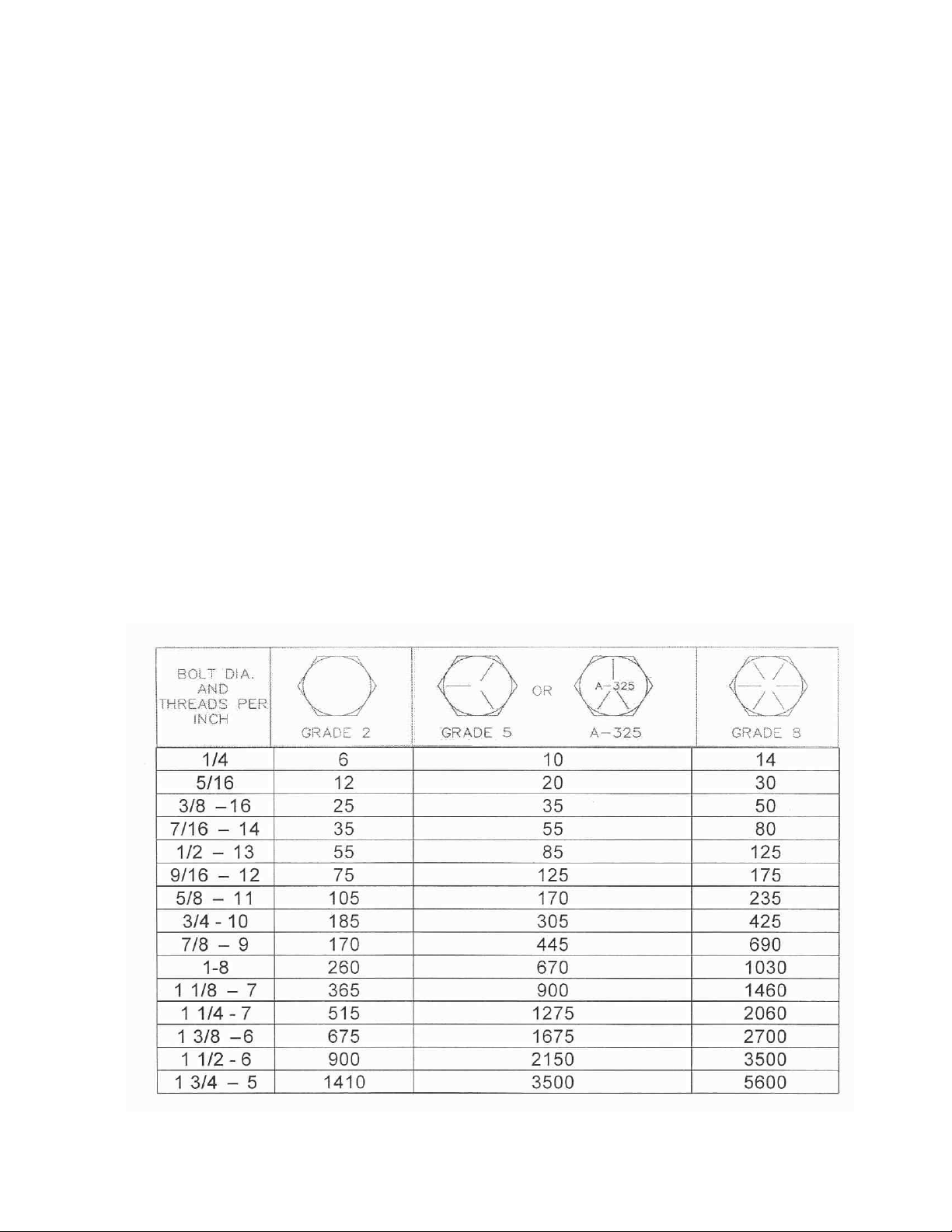
BOLT TORQUE
READ THESE INSTRUCTIONS FIRST:
1. Improperly tightened bolts will result in damage, breakage, expense, and down time.
2. Always replace bolts with the specified grade and type.
3. Torque properly before first use of the machine and every 2-4 hours of use until you are sure bolts
are staying tight.
4. The chart below is a guide for proper torque. Use it unless a specified torque is called out
elsewhere in the manual.
5. Torque is the force you apply to the wrench handle or the cheater bar, times the length of the handle
or bar.
6. Use a torque wrench whenever possible.
The following table shows torque in ft. lbs.
4
Page 5

ASSEMBLY INSTRUCTIONS
WARNING:
Never work under the toolbar while in a raised position without using safety lockups.
WARNING:
Use extreme caution, the blade is sharp and may cause bodily injury.
The 30” coulter that are mounted on 12” spacing will need to be completely assembled before mounting to
the toolbar.
NOTE: To aid the assembly of the opener, it is recommended that a stand be constructed to temporarily
attach the opener and hold it in an upright position.
CAUTION:
handling and or maneuvering the coulter during assembly is very important. Failure to do so may lead
to personal injury or death.
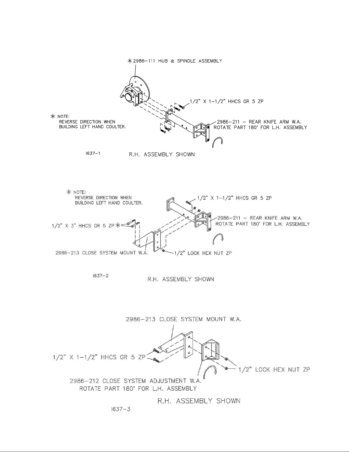
STEP 1. Attach the 2986-111 hub assembly and 2986-318 hub cap retainer to the 2986-106 main arm
assembly using (4) ½” x 1-1/2” hex head bolts. This step will determine right hand or left hand coulter
assembly.
The coulter and its components are very heavy. Extra attention to lifting techniques while
RIGHT HAND ASSEMBLY
5
Page 6
ASSEMBLY INSTRUCTIONS
STEP 2. Attach the 2986-211 Rear Knife Arm to the 2986-111 hub assembly using (4) ½” x 1-1/2” hex
head bolts. Make sure that the mount for the knife is on the same side of the arm as the spindle/blade.
STEP 3. Attach the 2986-213 Closing System Mount to the 2986-211 Knife Arm using (2) ½” x 3” hex
head bolts and (1) ½” x 1 ½” hex head bolt and ½” hex lock nuts.
STEP 4. Attach the 2986-212 Closing System Adjustment to the 2986-213 Closing System Mount Bracket
using (2) ½” x 1 ½” hex head bolts and ½” hex lock nuts.
6
Page 7
ASSEMBLY INSTRUCTIONS
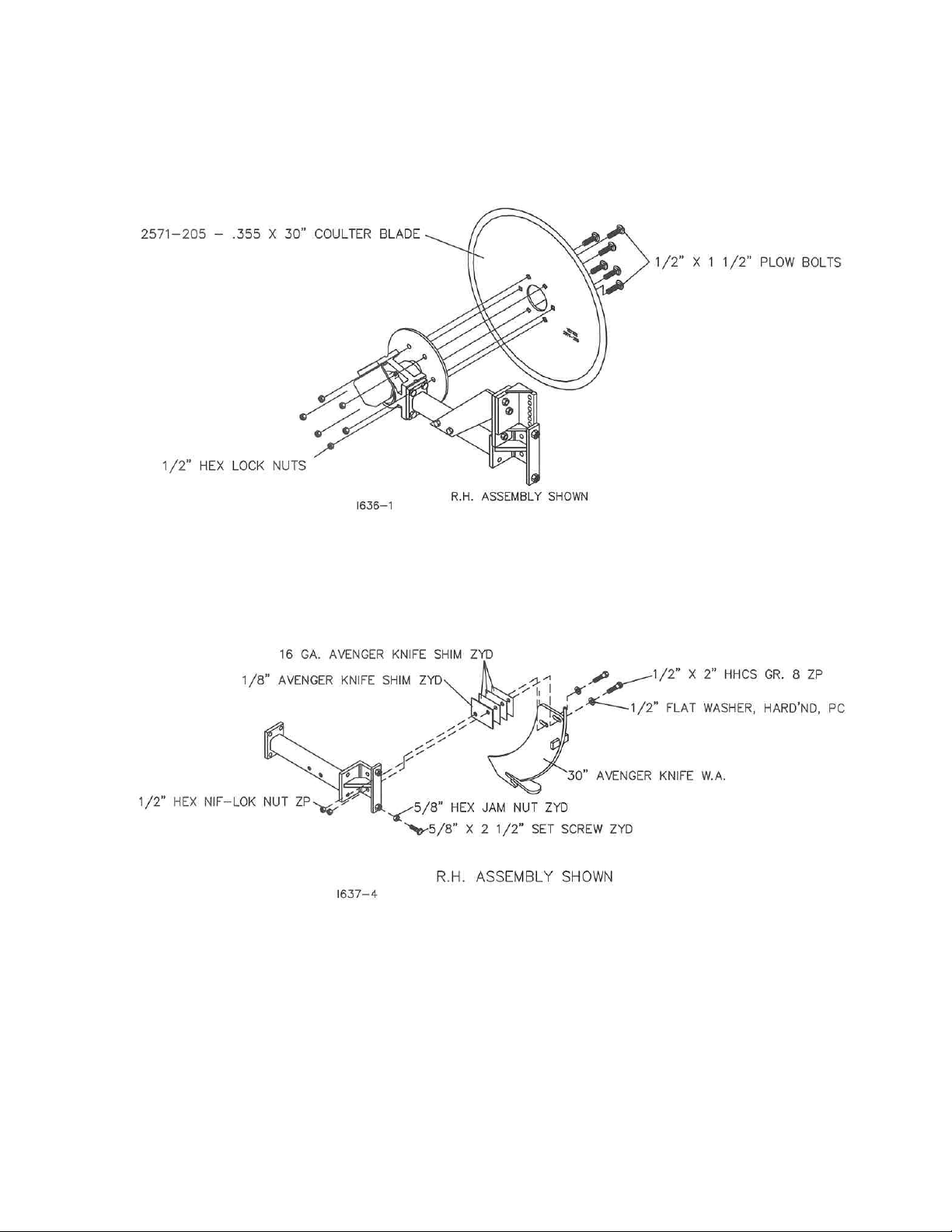
STEP 5. Attach the 30” blade 2571-205 to the 2986-111 hub assembly using (6) ½” x 1 ½” plow bolts and
½” hex lock nuts.
NOTE: The blade must be centered on the spindle. Bolts are to be just slightly tightened. At STEP 7
they are to be tightened securely and torqued to 90-96 FT/LBS.
STEP 6. Attach the Avenger Knife 2986-214 to the Knife Arm 2986-211 using shims as needed to align
the knife point with blade and using (2) ½” x 2” hex head bolts, hardened flat washers and ½” NIF-LOK
nuts.
STEP 7. Center the blade on the spindle, check by rotating blade and watching clearance between knife
and blade. Move the blade on the spindle as required until the blade runs concentric. Tighten (6) ½” lock
nuts, torque to 90-96 ft/lbs. THE BLADE MUST RUN CONCENTRIC.
STEP 8. Adjust knife clearance to blade as close as possible. The high point of the blade should clear
the knife no more than 1/64” max. as the blade is rotated. The blade should rotate freely. Tighten (2) ½”
x 2” hex bolts to 120 ft/lbs. Re-check clearances by rotating blade one full revolution after all bolts are
tight. Lock the knife in place by using the 5/8” x 2 ½” setscrew and 5/8” hex jam nut to prevent the knife
from moving rearward.
7
Page 8
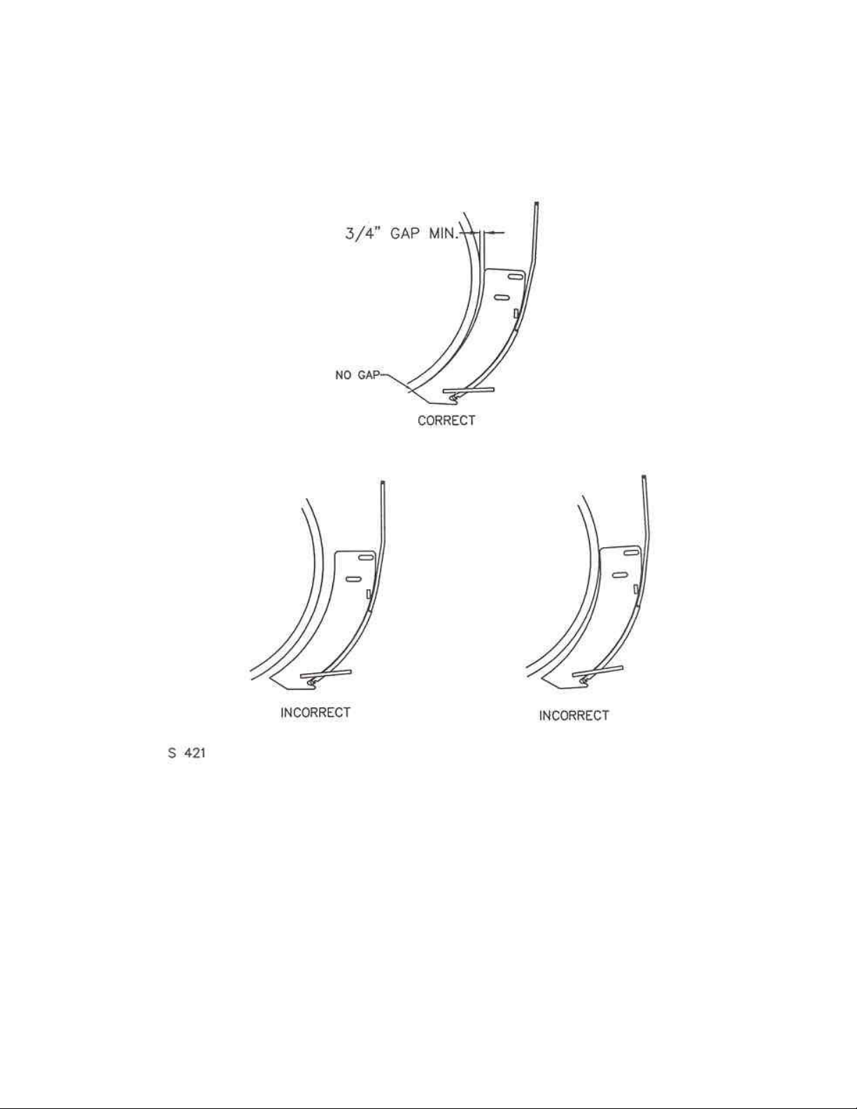
KNIFE ADJUSTMENT
The adjustment of knife clearance to the blade is critical to trouble free operation of the coulter, in certain
conditions the coulter can “plug” in just a few feet if not correctly adjusted.
1. The disc blade must run concentric. Adjust by loosening six hub nuts and centering the blade.
2. Set knife to rub slightly on blade, especially at bottom of knife. See illustrations above. Tighten NIFLOK nuts to 120 ft/lbs. by using the wrench on both the bolt head and the nut.
3. Adjust the 5/8” x 2 ½” bolt down against the stop of the knife to lock the knife in place, tighten the jam
nut to secure bolt.
8
Page 9
ASSEMBLY INSTRUCTIONS
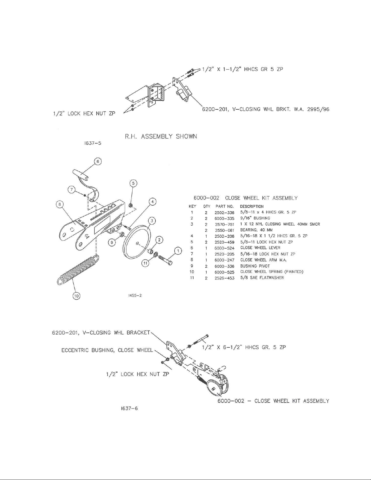
STEP 9. Attach the 6200-201 Closing Wheel Bracket to the 2986-212 adjustment bracket using (2) ½” x
1-½” hex head bolts and lock nuts. NOTE: Securely tightening the bolts at this step is not necessary
because the infield height adjustment will be done later for proper operation of the closing system.
STEP 10. Assemble the 6000-002 Close Wheel Kit as shown in illustration below.
STEP 11. Attach the 6000-002 Close Wheel Assembly to the 6200-201 Close Wheel Mount Bracket by
first inserting the hook of the spring through the hole of the mount bracket then use (1) ½” x 6 ½” hex
head bolt, eccentric bushings and ½” lock nut.
9
Page 10

ASSEMBLY INSTRUCTIONS
STEP 12. An eccentric bushing allows centering of the close wheels on the row. To properly apply
pressure on both sides of the slot when closing the trench. When adjusted properly, the closing wheels
are centered on the trench. To adjust, loosen the ½” x 6 ½” hex bolt that attaches the closing wheel
assembly to the wheel mount bracket. Rotate eccentric bushing with wrench to align closing wheel
assembly with center of trench. Tighten bolt that attaches closing wheel arm to wheel mount bracket.
10
Page 11

OPTIONAL EQUIPMENT
STEP 13. Assembly of 2986-108 Skid Shoe Kit.
The Skid Shoe can be attached to both R.H. and L.H. coulter assemblies. Begin by removing (2) ½” x 2”
bolts from the 2986-423 spring stop and save for the next step. Remove the bolts from the R.H. side
when working on a R.H. coulter or the bolts from the L.H. side when working on a L.H. coulter. Attach the
2986-327 to the spring stop using (2) ½” x 2” hex head bolts and reusing the locknuts that were saved
from the previous step. Next, attach the grease zerk 2533-110 to the arm 2986-209 and also insert
bushing 2986-422 (pre-lube bushing before installing) and attach to the 30” Coulter assembly using (1)
5/8” x 11” hex head bolt, (2) 5/8” flat washers and 5/8” hex lock nut. Attach the chain to the lower hole in
the arm using (1) ½” x 1 ½” hex head bolt, ½” flat washer and ½” hex lock nut. Hook the 6000-525 spring
to the chain link and hook the other end into 2986-326 Spring Adjust Lever. Attach the adjustment lever to
Lever Mounting Plate first using a ½” x 2 ½” hex head bolt, 2986-324 bushing and ½” hex lock nut in the
lower hole and using a ½” x 2 ½” bolt, tube spacer and ½” lock nut in the upper hole. Now attach the Skid
Shoe adjustment plate 2986-337 to the Skid Shoe Assembly 2987-107 using (1) 5/8” x 4” hex head bolt,
(2) 5/8” flat washers, ¾” spacer and (1) 5/8” hex lock nut. Fasten the Skid Shoe Assembly to the arm
2986-209 using (1) 5/8” x 3 ½” hex head bolt, (2) 5/8” flat washers and (1) 5/8” hex lock jam nut.
Adjust. Set the shoe to the blade, equally front and back. Start with no gap between the blade and shoe.
Set the shoe just touching the blade.
11
Page 12

ASSEMBLY INSTRUCTIONS
STEP 14. The coulter assembly is now ready to be mounted to the toolbar frame. YETTER suggests that
mounting of the coulters start at the center of the front toolbar using RIGHT HAND coulter assemblies. At
this time the 3-point hitch should already be mounted on the toolbar, if not, mount the 3-point hitch now.
After hitch is mounted, the coulter spacing should be marked out on the toolbar. For 12” opener spacing
the RIGHT HAND coulters mounted on the front bar will be spaced 24” on center. An example for even
numbers of openers is shown in the illustration below.
ILLUSTRATION SHOWN FROM TOP VIEW OF 12’ TOOLBAR WITH DIMENSIONS SHOWN TO BLADE CENTERS
Attach the coulter to the toolbar using the (4) ¾” x 12” hex head bolts, 2986-306 straps, ¾” lock washers
and ¾” hex nuts. (assembly view shown clearly in STEP 1.)
NOTE: I n the hitch area, the opener may use the same bolts as the 3-point hitch plates.
Once the coulters are mounted at the desired location and spacing, tighten the ¾” bolts to 300 ft/lbs.
12
Page 13

ASSEMBLY INSTRUCTIONS
STEP 15. Attach the 8” toolbar spacers 8000-200 to the rear of the toolbar using the 1” x 7” x 9” u-bolts,
lock washers and nuts provided. Do not over tighten the nuts as the spacers may have to be moved
slightly so not to interfere with the openers that are mounted to the rear toolbar frame.
NOTE: 12’ toolbar will need (6) 3600-123 – 8” Spacer Kits
16’ toolbar will need (8) 3600-123 – 8” Spacer Kits
21’ toolbar will need (10) 3600-123 – 8” Spacer Kits
COULTERS FROM PREVIOUS STEP NOT SHOWN FOR ASSEMBLY CLARITY
STEP 16. Attach the rear/second toolbar frame to the 8000-200 - 8” spacers using the remaining 1” x 7” x
9” u-bolts, lock washers and hex nuts provided.
NOTE: Do not over tighten the 1” hardware because the spacers may have to be moved slightly.
13
Page 14

ASSEMBLY INSTRUCTIONS
STEP 17. Attach the LEFT HAND coulter to the rear of the rear toolbar using (4) ¾” x 12” hex head bolts,
2986-306 strap, ¾” lock washers and ¾” hex nut. Once the coulters are mounted at the desired location
and spacing, tighten the ¾” bolts to 300 ft/lbs. Also at this time the 1” u-bolt hardware that attaches the
two toolbars together needs to be tightened securely.
RIGHT HAND COULTERS NOT SHOWN FOR ASSEMBLY CLARITY
14
Page 15

ASSEMBLY INSTRUCTIONS
STEP 18. Attach the (2) 3600-112 Parking Stand Kits to the front of the front toolbar using the ¾” x 7” x 9”
u-bolts, ¾” lock washers and ¾” hex lock nuts.
STEP 19. Attach the 3600-110 SMV Warning Kit to the rear toolbar, centering on the toolbar or as close
to the left of center as practical .
15
Page 16

OPERATION
Yetter Model 2986 30” coulter is designed to inject fumigant up to 12” deep. See your chemical dealer or
manufacturer for recommended depth and row spacing for the chemical that is to be used for your particular
application. A popular placement setting is 12” below the soil surface and 12” row spacing between
coulters.
IMPORTANT: For proper operation, the toolbar frame must operate level (for and aft) and at the correct height,
usually 22” – 25” while in operation.
In hard no-till conditions the desired operating depth may not be possible. Tighten the spring pressure
adjustment to obtain maximum depth if spring is flexing rather than lower the toolbar frame below the 22”
minimum recommended setting.
Toolbar weight may limit operating depth in hard soil conditions, particularly with tractor mounted toolbars.
Add ballast to the toolbar frame. Example, 200 lb. per coulter has been added to get desired depth. The
tractor may have to be equipped with a rear hitch hydraulic down force kit to obtain the optimum toolbar
frame operating height of 22”-25”. Blade operating depth is affected by spring tension, toolbar height,
levelness of toolbar for and aft and soil conditions. As soil conditions change, toolbar settings and coulter
adjustments will need to be changed as well.
Toolbar gauge wheel kits are optional, but recommended for use with the Avenger coulter because of
toolbar frame height being very critical.
1. Set/mount coulter blades to run vertical to ground. Operation depth and blade wear can be affected if
coulter is mounted crooked or if toolbar is not level side to side.
2. After a few hours use, check all bolts and setscrews for tightness and proper torque settings.
3. After a day of use (10-12 hours), check coulter hubs for loose bearings. There should be no end play in
the hub bearings to allow it to wobble. If necessary, remove hub cap and cotter pin, adjust slotted nut to
remove wobble, recommended torque of 13 ft/lbs, re-insert cotter pin and replace hub cap. If the wobble
or looseness can not be corrected, the bearings, cups and seal will need to be replaced. DO NOT REUSE WORN OR DAMAGED PARTS.
4. KNIFE ADJUSTMENT IS CRITICAL. Adjust knife-blade clearance regularly, see page 8 of this manual.
Blade wear can affect operation in loose soil conditions. If knife adjustment does not stop plugging
problems, it may be necessary to replace the 30” blade.
16
Page 17

OPERATION
TOOLBAR FRAME HIEGHT ADJUSTMENT
Figure A. The toolbar frames are equally 22”-25” off the ground. To ensure that frame heights are equal,
it is important that measurements are taken. The tube frames should be parallel with the soil surface.
Figure B. The hitch is set too low while the toolbar frames are not equal distance from the soil surface.
NOTE: The illustrations are intended to show that the settings are critical. Tool frame levelness and
height adjustment are very important settings for correct performance of the coulters.
17
Page 18

OPERATION
CAUTION:
wheels.
CLOSING WHEELS. Angled closing wheels trail behind the opener to close the trench left by the blade.
Adjustable spring pressure permits proper firming of soil beside the trench rather than directly above it.
An eccentric bushing allows centering of the closing wheel on the row to properly apply pressure on both
sides of the slot when closing the trench. When adjusted properly, the closing wheels are centered on the
trench.
To adjust, loosen the bolt that attaches the closing wheel arm to wheel mount bracket. Rotate the
eccentric bushing with wrench to align the closing wheel assembly with center of trench. Tighten bolt that
attaches closing wheel arm to wheel mount bracket.
Raise toolbar to transport position and install all safety locks before adjusting the closing
NOTE: After setting coulter to correct depth, check operation of closing wheels. The closing wheels must
apply enough down pressure to close the trench and insure a good seal at the soil surface.
18
Page 19

OPERATION INSTRUCTIONS
RIGHT HAND ASSEMBLY
DIRECTION OF TRAVEL
1. Adjust the shoe the same front and back.
2. Start with no gap between the blade and shoe.
3. Set the shoe just touching the blade.
OPERATION MAINTENANCE
LUBRICATION: Each coulter is equipped with (3) grease zerks. To ensure longevity and reliability of
the coulter, the recommended lubrication schedule should be followed using general purpose grease
at hourly intervals indicated on symbol.
19
Page 20

OPERATION MAINTENANCE
BEARING ADJUSTMENT:
1. Raise the toolbar until the blade is clear of the ground. Place a safety stand under the toolbar.
Remove the blade. Remove the hub cap, cotter pin, slotted nut, washer and spacer from the
spindle shaft assembly.
2. Pull the coulter spindle shaft assembly from the hub. Remove bearing cones and seal.
3. Wash the old grease from the hub, bearing cups, coulter spindle shaft, seal and bearing cones.
Inspect the condition of bearing cups, cones and seal. Replace if necessary.
4. Apply #2 multi-purpose lithium grease on each bearing. Make sure the space around each roller
is filled. Lubricate the bearing cups.
5. Position the bearing in the cup and install the seal. Lubricate the seal lips and proceed with re-
assembly of the removed parts including the blade. Blade bolt torque is 90 to 96 ft/lbs.
6. Tighten the slotted nut to 10 to 15 ft/lbs. or until a definite drag is felt when the blade is turned by
hand. Back off the nut one slot position to line up the cotter pin hole with a slot. Secure the nut
with a new cotter pin.
KNIFE WEAR:
The lower portion of the knife and tube are subject to wear during operation. The rate of wear will
depend on a variety of factors and in abrasive soil conditions the wear will be more rapid.
NOTE: In certain areas, replacement knives should be kept in stock, replacing worn knives as
needed.
20
Page 21

PARTS IDENTIFICATION
Right Hand Assembly Shown
All hardware shown is included in the 2986-130 bolt bag.
2986-030 – 30” AVENGER COULTER
KEY QTY. PART NUMBER DESCRIPTION
1 1 2986-106 MAIN ARM ASSEMBLY, STAIGHT MOUNT
2 1 2571-205 .355 X 30” COULTER BLADE
3 1 2986-130 30” AVENGER COULTER PARTS BUNDLE
4 1 6000-002 CLOSE WHEEL KIT
21
Page 22

PARTS IDENTIFICATION
22
Page 23

PARTS IDENTIFICATION
2986-106 - MAIN ARM ASSY., STRAIGHT MOUNT
KEY QTY. PART NUMBER DESCRIPTION
1 1 2530-214 3/8 X 2 ¼ ROLL PIN.
2 1 2986-305 PIN, MTG. BRACKET PIVOT
3 1 2986-210 AVENGER MOUNT W .A., STRAIGHT
4 4 2502-351 ½-13 X 2 HHCS GR 5 ZYD
5 1 2986-200 MOUNTING BRACKET W .A.
6 4 2520-515 ¾-10 HEX LOCK NUT ZYD
7 1 2502-523 ¾-10 X 15 ½ HHCS GR 5 ZYD
8 3 2502-503 ¾-10 X 2 HHCS GR 5 ZYD
9 1 2986-401 MOUNTING ARM
1 2533-110 ¼-28 ZERK STRAIGHT SELF-TAP
10 4 2520-357 ½-13 HEX LOCK NUT ZYD
11 2 2986-405 SPRING BUSHING
12 1 2986-342 COMPRESSION SPRING, AVENGER
13 1 2986-423 SPRING STOP
14 1 2550-771 10” POLY HELPER SPRING
15 1 2526-501 ¾ STANDARD FLAT WASHER ZYD
16 2 2565-366 AVENGER COULTER DECAL
17 1 2565-423 AVENGER “IMPORTANT” DECAL
23
Page 24

PARTS IDENTIFICATION
KEY QTY. PART NUMBER DESCRIPTION
1 1 2550-065 DUST CAP, #909912
2 1 2986-329 MACH. CASTLE NUT 1 ¼-12
3 1 2531-124 3/16 X 2 COTTER PIN
4 1 2526-562 1 17/64 ID X 2 ¼ OD X 10 GA. MB BLK
5 2 2550-057 BEARING, KOYO #2788R
6 1 2986-403 MOUNTING HUB
1 2533-110 ¼-28 ZERK STRAIGHT SELF-TAP
2 2550-056 CUP, KOYO #2729
7 1 2550-058 SEAL, CR #17699
8 1 2986-402 25” COULTER SPINDLE
NOTE: Detail #2 is to be torqued to between 12 and 15 ft/lbs.
24
Page 25

PARTS IDENTIFICATION
2986-108 MAIN ARM & SKID SHOE ASSEMBLY
KEY QTY. PART NUMBER DESCRIPTION
1 1 2502-348 5/8-11 X 11 HHCS GR 5 ZYD
2 2 2520-357 ½-13 HEX LOCK NUT ZYD
3 1 2986-327 LEVER MOUNTING PLATE
4 1 2986-324 LEVER PIVOT BUSHING
5 1 2960-372 SPRING STOP, ZYD.
6 1 2986-326 SPRING ADJUSTING LEVER
7 2 2526-351 ½ STANDARD FLAT WASHER ZYD
8 2 2502-296 ½-13 X 2 ½ HHCS GR 5 ZYD
9 1 6000-525 CLOSE WHEEL SPRING, PAINTED
10 1 2986-422 5 13/32” INNER BUSHING
11 1 2986-209 AVENGER STRAIGHT ARM W .A.
12 1 2533-110 ¼-28 ZERK, STRAIGHT SEFL-TAP
13 1 2502-324 5/8-11 X 3 ½ HHCS GR 5 ZYD
14 2 2520-459 5/8-11 HEX LOCK NUT ZYD
15 6 2526-451 5/8 STANDARD FLAT W ASHER ZYD
16 1 2502-294 ½-13 X 1 ½ HHCS GR 5 ZYD
17 1 2565-366 AVENGER COULTER DECAL
18 1 2967-381 COMBO ADJUSTMENT PIN ZYD
19 1 2986-337 SKID SHOE ADJUSTMENT PLATE
20 1 2520-467 5/8-11 HEX LOCK JAM NUT ZYD
21 1 2967-302 SPACER, ¾ ZYD
22 1 2570-448 1/8 STD. HAIRPIN COTTER ZYD
23 1 2986-332 5/16 CHAIN 2 LINKS
24 1 2502-336 5/8-11 X 4 HHCS GR 5 ZYD
25 1 2986-208 AVENGER SKID SHOE W .A.
26 1 2520-352 ½-13 HEX NUT ZYD
27 1 2525-352 ½ MED. LOCK WASHER ZYD
28 1 2986-340 4 1/4" POLY SKID SHOE
29 6 N10213 5/16-18 HEX FLANGE SERRATED NUT
30 6 2505-206 5/16-16 X 1 CAR BOLT GR 5 ZYD
25
Page 26

TROUBLESHOOTING
Problem
Closing wheels are plugging
Fumigant too shallow
Fumigant will not flow
Blade not turning properly
Residue/Plastic pluggingwedging between blade and
knife
Blade not penetrating
Cause
Mounting bracket height
adjusted too low
Closing wheels are mounted
side by side
Spring tension setting is too
heavy
Blade not penetrating deep
enough
Injection knife worn
Hole worn in injection tube
Kinked/Crushed supply hose
Injection tube is plugged
Bearing seized in the hub
assembly
Loose soil
Excessive blade knife
clearance
Knife not correctly aligned
behind blade
Toolbar height too high
Insufficient coulter spring
tension
Too much spring tension on
close wheels
Lack of toolbar weight
Solution
Adjust the mounting bracket
so that the wheel arm is
parallel or running slightly
uphill to soil surface.
Mount the closing wheels
offset. One forward, one back.
Adjust spring tension to a
lighter-forward-position.
Increase/Tighten coil spring
tension.
Replace knife.
Repair tube or replace
knife/tube assembly.
Replace supply hose.
Check for obstruction in
injection tube.
Repair/replace worn cups,
cones and seals.
Increase blade cutting action
by adding a shim to the
Avenger mount bracket at the
toolbar on the side opposite
the blade.
Knife adjustment should be as
close as possible at tip but
provide maximum opening at
upper end.
Use shims more/less to align
knife directly behind the blade.
Adjust height of toolbar to 22”25” above soil surface.
Increase tension on coil spring
– turn lock nut clockwise.
Adjust spring tension on
closing wheel to lightest
setting.
Add additional ballast to the
toolbar frame.
Example: 200# per coulter.
Refer to tractor O/M for hitch
lift capacity.
26
Page 27

Problem
Coulter blade not deflecting –
spring not flexing
Coulter damaged
Closing wheels do not seal
trench
Unable to seal in fumigants
properly
TROUBLESHOOTING
Cause
Excessive spring pressure
Rocky conditions
Toolbar height too low, limiting
coulter travel
Insufficient coulter spring
tension
Toolbar height is too low
Conditions, soil, adjustments
and settings
Solution
Decrease tension on coil
spring – turn lock nut
counterclockwise.
Remove poly helper spring
from inside the coil spring.
Remove poly helper spring
from inside the coil spring.
Adjust height of toolbar to 22”25” above soil surface.
Increase tension on coil spring
– turn lock nut clockwise.
Adjust height of toolbar to 22”25” above soil surface.
Stop application and contact
your fumigant supplier or
Yetter Manufacturing Co. at
1-800-447-5777
27
Page 28

Our name
Is getting known
Just a few years ago, Yetter products were sold primarily
to the Midwest only. Then we embarked on a program of
expansion and moved into the East, the South, the West
and now north into Canada. We’re even getting orders from
as far away as Australia and Africa.
So, when you buy Yetter products . . .you’re buying a name
that’s recognized. A name that’s known and respected. A name
that’s become a part of American agriculture and has become
synonymous with quality and satisfaction in the field of
conservation tillage.
Thank you.
YETTER MANUFACTURING CO.
COLCHESTER, IL 62326-0358 309/776-4111
TOLL FREE 800/447-5777
FAX 309/776-3222
WEBSITE: WWW.YETTERCO.COM
E-MAIL: INFO@YETTERCO.COM
2565-480_REV_D 07/13
 Loading...