

Page 1

25” AVENGER COULTER
OPERATORS MANUAL
WITH PARTS IDENTIFICATION
2565-419_REV_E 07/2013
YETTER MANUFACTURING CO.
FOUNDED 1930
Colchester, IL 62326-0358
Toll free: 800/447-5777
309/776-3222 (Fax)
Website: www.yetterco.com
E-mail: info@yetterco.com
Page 2

FOREWORD
You’ve just joined an exclusive but rapidly growing
club.
For our part, we want to welcome you to the group
and thank you for buying a Yetter Avenger Coulter.
This is a unique and revolutionary new product.
We hope your new Avenger coulter will help you
achieve both increased productivity and increased
efficiency so that you may generate more profit.
This operator’s manual has been designed into
four major sections.
Foreword, Safety Precautions, Installation and
Operation.
Throughout the manual references may be made
to left side and right side. These terms are used
as viewed from the operator’s seat facing the front
of the tractor.
This SAFETY ALERT SYMBOL
indicates important safety messages
in the manual. When you see this symbol, be
alert to the possibility of PERSONAL INJURY
and carefully read the message that follows.
The word NOTE is used to convey information that
is out of context with the manual text. It contains
special information such as specifications,
techniques, reference information of a
supplementary nature.
The word IMPORTANT is used in the text when
immediate damage will occur to the machine due
to improper technique or operation. Important will
apply to the same information as specified by note
only of an immediate and urgent nature.
It is the responsibility of the user to read the
operator’s manual and comply with the safe and
correct operating procedure and to lubricate and
maintain the product according to the maintenance
schedule in the operator’s manual.
The user is responsible for inspecting his machine
and for having parts repaired or replaced when
continued use of the product would cause damage
or excessive wear to the other parts.
It is the user’s responsibility to deliver his machine
to the Yetter dealer who sold him the product for
service or replacement of defective parts which
are covered by the warranty policy.
IMPORTANT: When raising 3 pt. Toolbars watch
tractor tire clearance. EXAMPLE: In most cases 3
pt. hitches require a cat. 2 or cat. 3 quick hitch
coupler to offset toolbar away from tractor tires.
YETTER MANUFACTURING CO.
309/776-4111
800/447-5777
309/776-3222 (FAX)
WARRANTY POLICY
Yetter Manufacturing warrants all products manufactured and sold by it against defects in material. This
warranty being expressly limited to replacement at the factory of such parts or products as will appear to
be defective after inspection. This warranty does not obligate the Company to bear cost of labor in
replacement of parts. It is the policy of the company to make improvements without incurring obligations
to add them to any unit already sold. No warranty is made or authorized to be made, other than herein set
forth. This warranty is in effect for one year after purchase.
Model Number:_________________________
Dealer :_______________________________
Yetter Manufacturing warrants its own products only and cannot be responsible for damage to
equipment on which mounted.
2
Page 3

SAFETY
A brief description of signal words that may be used in this manual:
CAUTION: Used as a general reminder of good safety practices or to direct attention to unsafe practices.
WARNING: Denotes a specific potential hazard.
DANGER: Denotes the most serious specific potential hazard.
SAFETY PRECAUTIONS
You can make your farm a safer place to live and work if you observe the safety precautions given. Study
these precautions carefully and insist that they be followed by those working with you and for you.
Finally, remember this: an accident is usually caused by someone’s carelessness, neglect or oversight.
WARNING
Never clean, lubricate or adjust a machine that is in motion. Always lower or block the implement before
performing service.
If the machine must be serviced in the raised position, jack or block it up to prevent it from accidentally
falling and injuring someone.
Do not allow riders on the tractor or implement.
Use speeds and caution dictated by the terrain being traversed. Do not operate on any slope steep enough
to cause tipping or loss of control.
Be sure all personnel are clear of the immediate area before operating.
Read and understand the operator’s manual and require all other persons who will operate the equipment to
do the same.
Be familiar with all tractor and implement controls and be prepared to stop engine and implements quickly in
an emergency.
CAUTION
Consult your implement and tractor operator’s manual for correct and safe operating practices.
Beware of towed implement width and allow safe clearance.
FAILURE TO HEED MAY RESULT IN PERSONAL INJURY OR DEATH.
3
Page 4

GENERAL INFORMATION
Examine all equipment carefully for damage or shortages.
2986-125 Avenger with Standard Mount
2986-124 – Avenger Main Arm Box
2986-126 – Avenger Standard Mount Kit
2571-200 – 25” Coulter Blade
2986-122 Avenger with 4 X 4 Mount
2986-124 – Avenger Main Arm Box
2986-123 – Avenger 4 X 4 Mount Kit
2571-200 – 25” Coulter Blade
NOTE: Right hand coulter can be converted to left hand coulter and left hand coulter can be converted to
right hand coulter.
Optional Equipment Available: 2986-108 – Skid Shoe Kit.
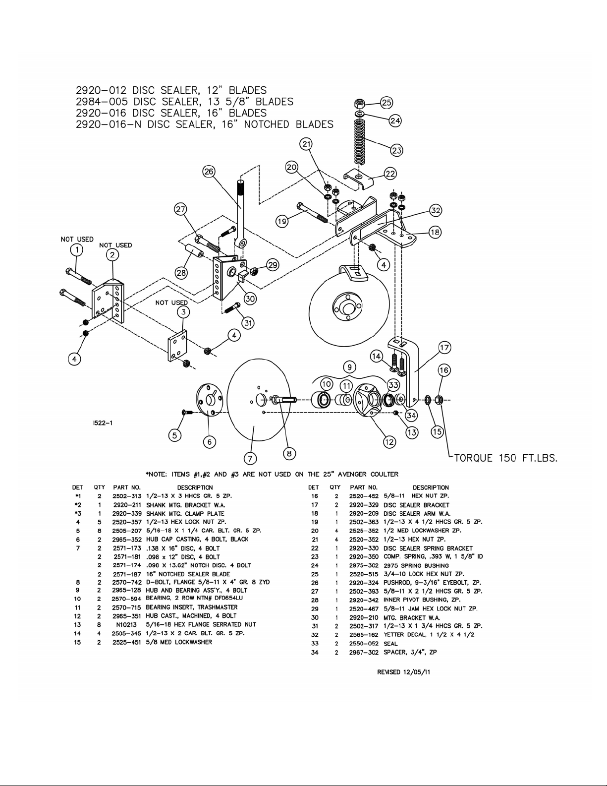
2920-012 – 12” Smooth Disc Sealer Kit
2984-005 – 13 5/8” Notched Disc Sealer Kit
2920-016 – 16” Smooth Disc Sealer Kit
2984-009 – Sealing Wheel Kit
2920-016-N – 16” Notched Disc Sealer Kit
Lubricate all bearings and moving parts as you assemble and see that they work freely.
NOTE: When you are behind the coulter looking forward, the right hand coulter is assembled with the blade to
the right hand of the arm assembly. The left hand coulter is assembled with the blade to the left hand of the arm
assembly.
READ THESE INSTRUCTIONS FIRST:
1. Improperly tightened bolts will result in damage, breakage, expense, and down time.
2. Always replace bolts with the specified grade and type.
3. Torque properly before first use of the machine and every 2-4 hours of use until you are sure bolts are staying
tight.
4. The chart below is a guide for proper torque. Use it unless a specified torque is called out elsewhere in the
manual.
5. Torque is the force you apply to the wrench handle or the cheater bar, times the length of the handle or bar.
6. Use a torque wrench whenever possible.
The following table shows torque in ft. lbs.
4
Page 5
ASSEMBLY INSTRUCTIONS
The Avenger coulter is designed to mount to rectangular toolbars in three sizes: 5” x 7”, 6” x 6”or 7” x 7”.
WARNING:
lockups.
Never work under the toolbar while in a raised position without using safety
WARNING:
The Avenger coulter can be mounted to the toolbar using different techniques. One way is to
mount the main arm assembly to the toolbar and then attach the components one at a time. Another way is
to completely assemble the avenger coulter before attaching to the toolbar frame.
NOTE: To aid the assembly of the opener, it is recommended that a stand be constructed to temporarily
attach the opener and hold it in an upright position.
CAUTION:
techniques while handling and or maneuvering the coulter during assembly is very important.
Failure to do so may lead to personal injury or death.
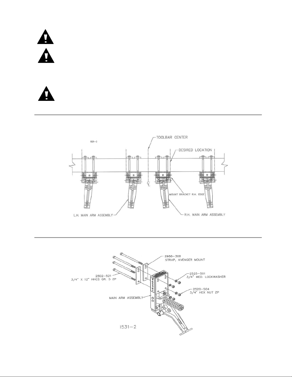
STEP 1. Mark the toolbar frame as to the location that each coulter is to be mounted. Right hand
assemblies are usually mounted on the right hand side of the toolbar and the left hand assemblies are
mounted on the left hand side of the toolbar.
Use extreme caution, the blade is sharp and may cause bodily injury.
The Avenger coulter and its components are very heavy. Extra attention to lifting
NOTE: The coulter blade is in line with the edge of the mount bracket, for a reference use the edge of the
mounting bracket (right hand edge for a right hand and left hand edge for a left hand) to align with the mark
on the toolbar so that the coulters are mounted at the desired spacing.
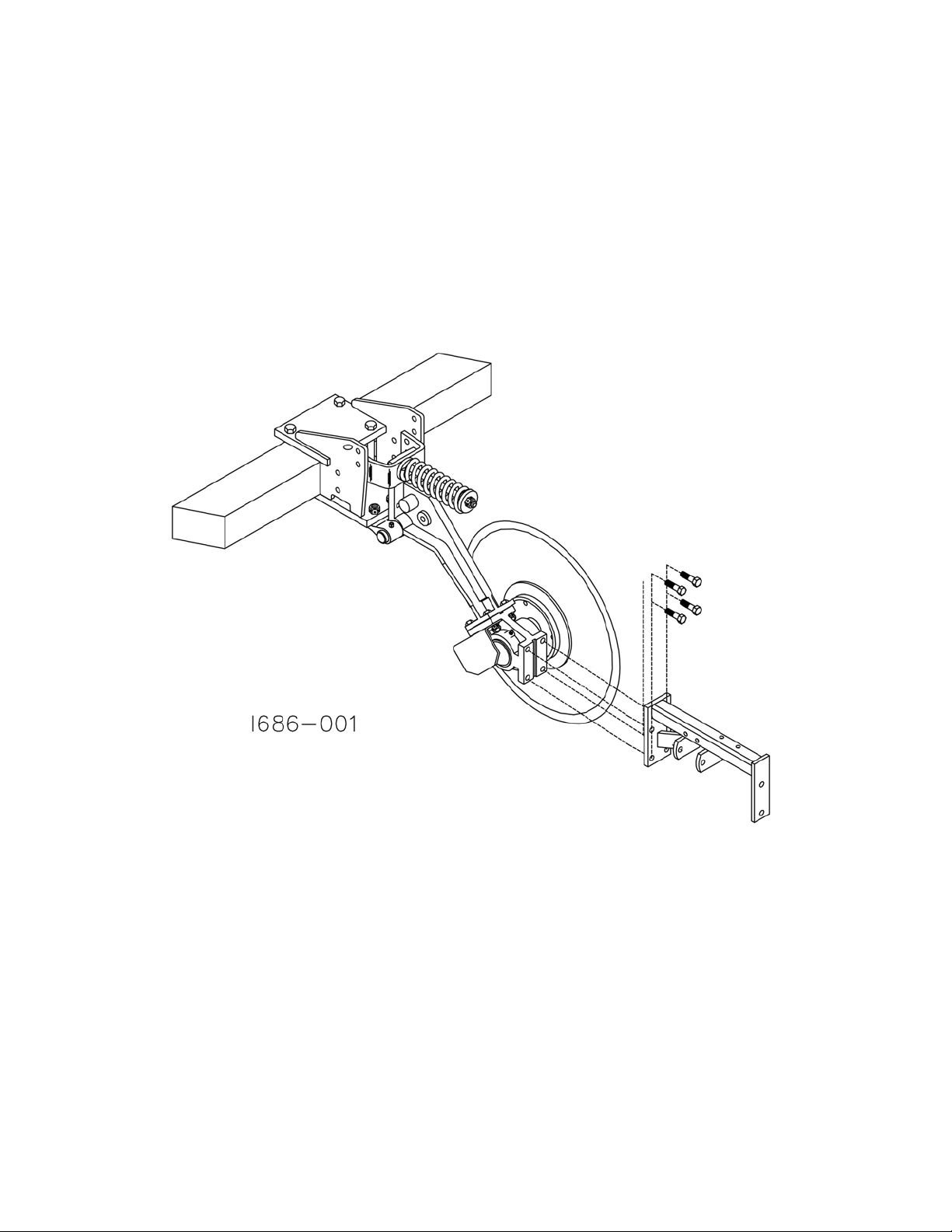
STEP 2. Attach the main arm assembly to the toolbar using 2) 2986-306 mounting straps, 4) ¾” x 12” hex
head bolts, ¾” lock washers and ¾” hex nuts.
5
Page 6
ASSEMBLY INSTRUCTIONS
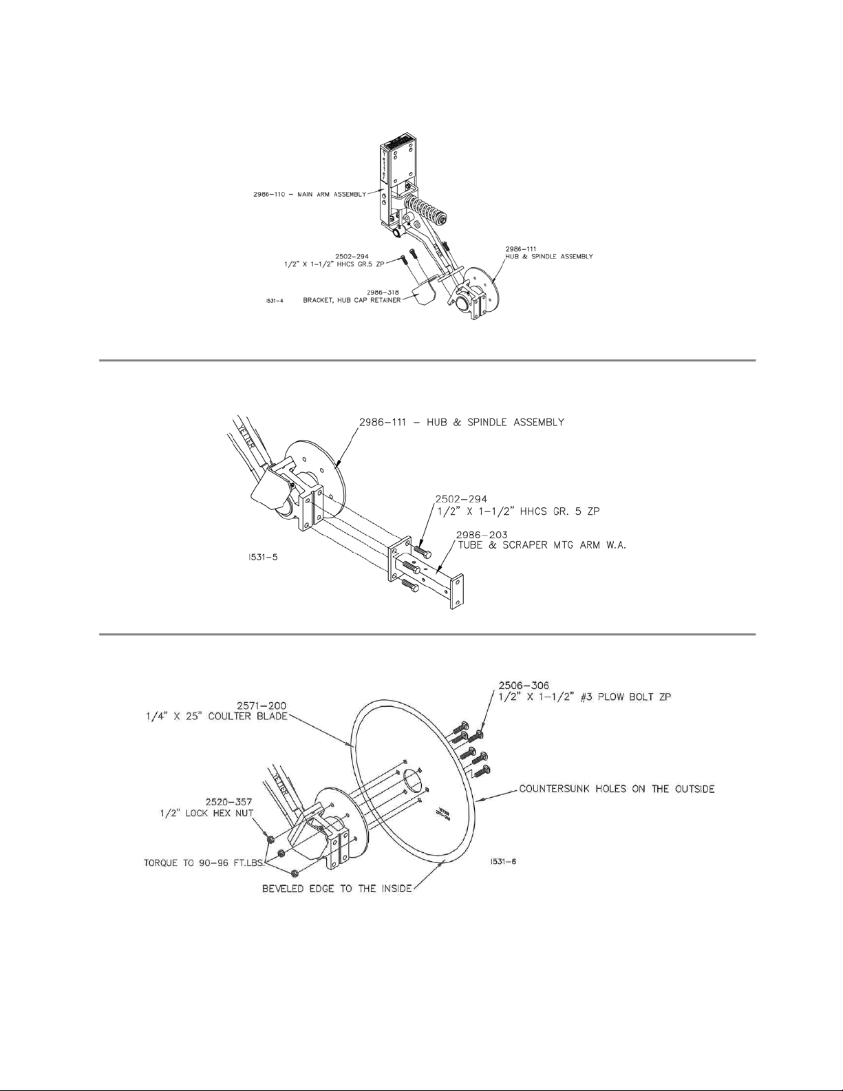
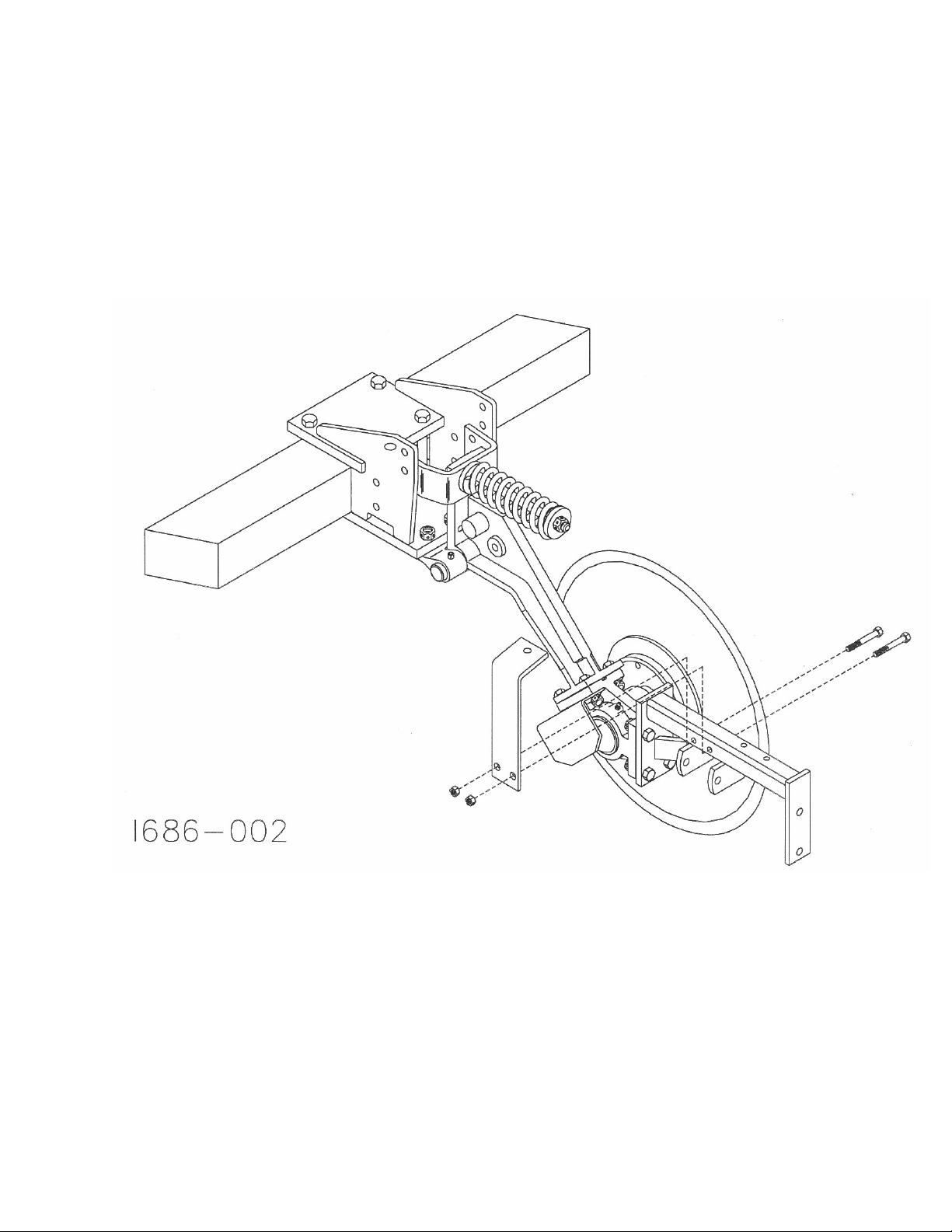
STEP 3. Attach the 2986-111 hub and spindle assembly and the 2986-318 hub cap retainer to the 2986-
110 main arm assembly using 4) ½” x 1-1/2” hex head bolts. The spindle hub will be mounted on the right
hand side for a right hand coulter and on the left hand side for a left hand coulter.
STEP 4. Attach the 2986-203 tube and scraper mount arm to the 2986-111 hub assembly using 4) ½” x
1-1/2” hex head bolts.
STEP 5. Attach the 2571-200 – 25” coulter blade to the 2986-111 hub and spindle using 6) ½” x 1 ½” plow
bolts and ½” hex lock nuts. Tighten buts to 90-96 ft. lbs. of torque.
6
Page 7
ASSEMBLY INSTRUCTIONS
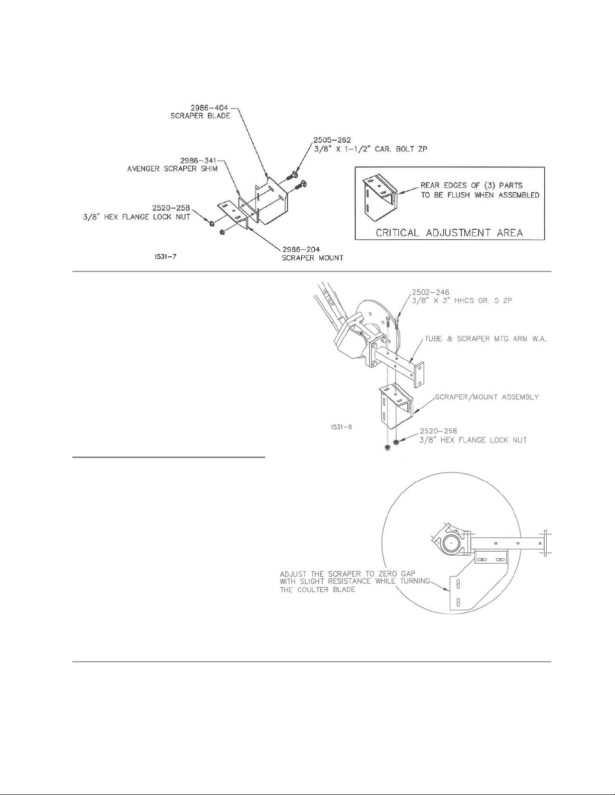
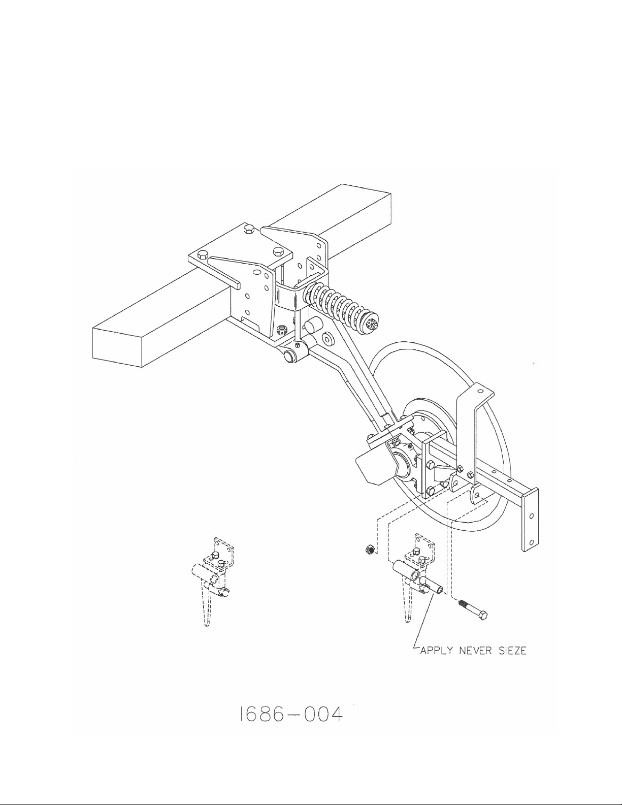
STEP 6. Assemble the 2986-404 scraper, 2986-341 shim and 2986-204 scraper mount w.a. using 2) 3/8” x
1 ½” smooth head carriage bolts and 3/8” flanged hex lock nuts. Adjust the scraper to the mount so that the
rear edges are flush with each other.
STEP 7. Attach the scraper and mount
assembly (from step 6) to the scraper
mounting arm using 2) 3/8” x 3” bolts and
3/8” flange lock nuts.
NOTE: Adjust the 2986-404 scraper to the
2571-200 blade . There should be zero
tolerance gap between the front edge of
the scraper and the blade, but the blade
should be able to turn with only slight
resistance.
CRITICAL ADJUSTMENT AREA
7
Page 8
ASSEMBLY INSTRUCTIONS
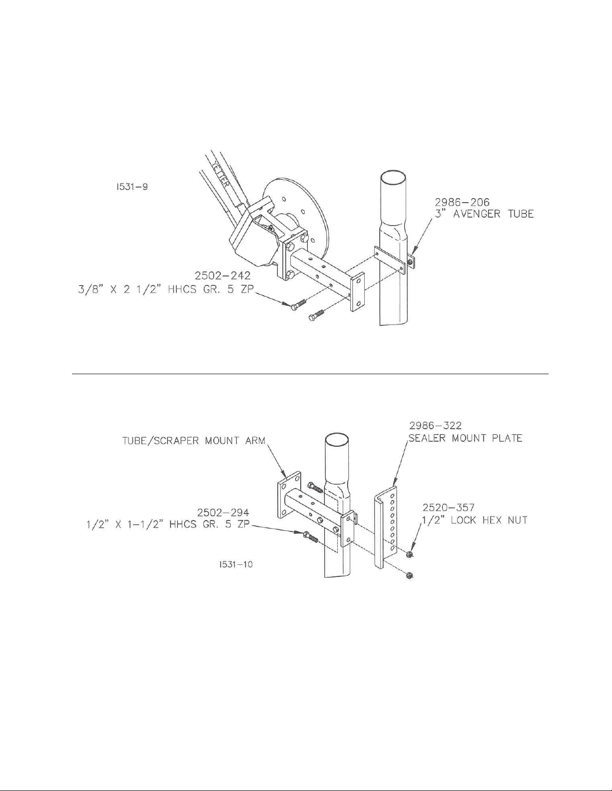
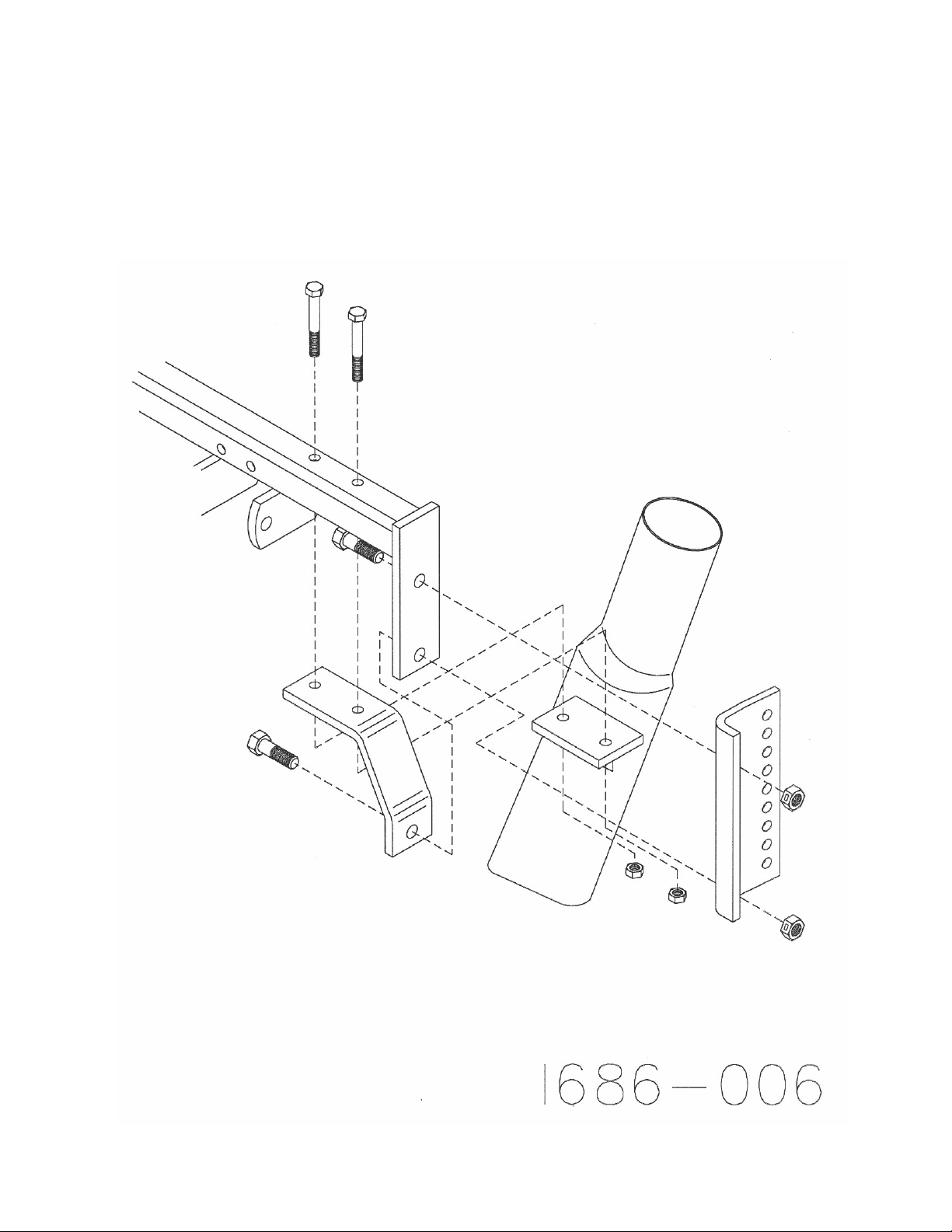
STEP 8. Attach the 2986-206 3” Avenger tube to the 2986-203 tube/scraper mount arm using 2) 3/8” x 2 ½”
bolts. Insert the bolts through the two most rear holes of the mount arm.
STEP 9. Attach the 2986-322 sealer mount plate to the 2986-203 tube scraper mount arm using 2) ½” x 1
½” hex head bolts and ½” lock nuts.
8
Page 9
ASSEMBLY
2986-120 SPRING LOADED SCRAPER
Step 1. Attach the 2986-218 knife arm to the coulter hub using the 4) 1/2” x
1-1/2” bolts.
9
Page 10
ASSEMBLY
2986-120 SPRING LOADED SCRAPER
Step 2. Attach the 2986-343 spring adjustment to the knife arm using the 2)
3/8” x 3” bolts and flange nuts.
10
Page 11

ASSEMBLY
2986-120 SPRING LOADED SCRAPER
Step 3. Assemble the 2986-215 scraper blade to the 2986-216 lower pivot,
apply never seize to the shaft and secure with the roll pin. Attach the 2986345 spring anchor and the 2986-217 upper knife pivot to the 2986-216 lower
knife pivot using 2) 3/8” x 1-1/2” bolts and lock washers.
11
Page 12
ASSEMBLY
2986-120 SPRING LOADED SCRAPER
Step 4. Attach the knife assembly to the knife arm using the 1/2” x 4” bolt,
2986-346 bushing and lock nut.
12
Page 13

ASSEMBLY
2986-120 SPRING LOADED SCRAPER
Step 5. Attach the springs to the 2986-221 adjustment block using the 2)
7/16” x 1-1/4” bolts and lock washer. Attach the springs to the knife
assembly then attach the spring adjustment assembly to the 2986-343
adjustment plate using the 1) 7/16” x 4-1/2” bolt, washer & hex nut.
Apply never seize
13
Page 14

Step 5A.
ASSEMLBY
2986-120 SPRING LOADED SCRAPER
14
Page 15
ASSEMBLY
2986-120 SPRING LOADED SCRAPER
Step 6. Attach the 3” Liquid tube and the 2986-344 knife arm brace to the
knife arm using 2) 3/8” x 3-1/4” bolts, 2) 1/2” x 1-3/4” bolts and lock nuts.
15
Page 16

Step 6A.
•
ASSEMBLY
2986-120 SPRING LOADED SCRAPER
16
Page 17
ASSEMBLY INSTRUCTIONS
OPTIONAL EQUIPMENT
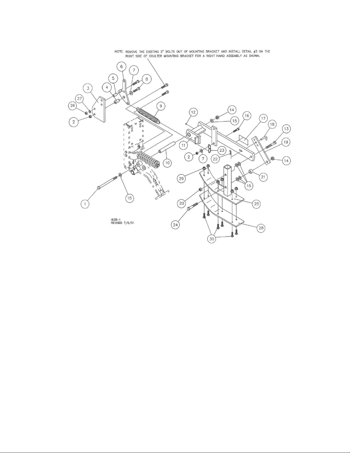
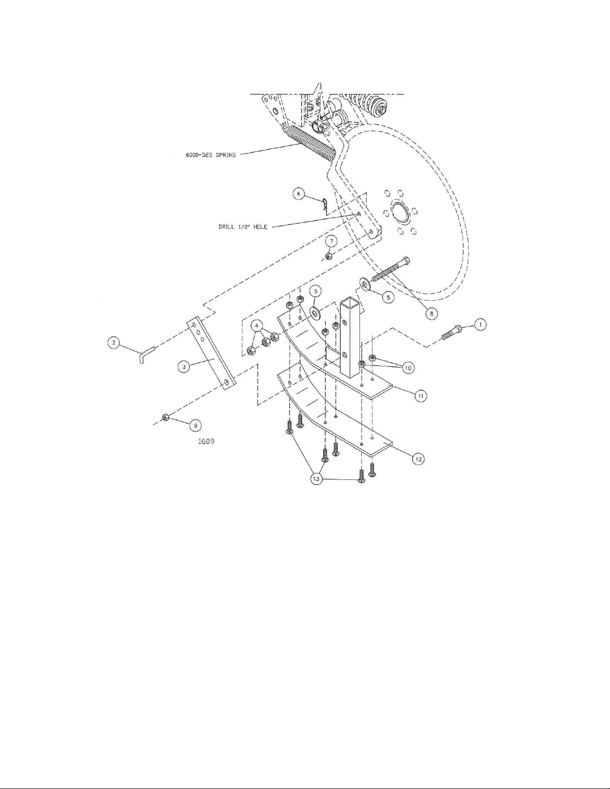
Assembly of 2986-108 Skid Shoe Kit.
The Skid Shoe can be attached to both R.H. and L.H. coulter assemblies. Begin by removing (2) ½” x 2”
bolts from the 2986-423 spring stop and save for the next step. Remove the bolts from the R.H. side when
working on a R.H. coulter or the bolts from the L.H. side when working on a L.H. coulter. Attach the 2986327 to the spring stop using (2) ½” x 2” hex head bolts and reusing the locknuts that were saved from the
previous step. Next, attach the grease zerk 2533-110 to the arm 2986-209 and also insert bushing 2986422 (pre-lube bushing before installing) and attach to the 25” Coulter assembly using (1) 5/8” x 11” hex
head bolt, (2) 5/8” flat washers and 5/8” hex lock nut. Attach the chain to the lower hole in the arm using (1)
½” x 1 ½” hex head bolt, ½” flat washer and ½” hex lock nut. Hook the 6000-525 spring to the chain link and
hook the other end into 2986-326 Spring Adjust Lever. Attach the adjustment lever to Lever Mounting Plate
first using a ½” x 2 ½” hex head bolt, 2986-324 bushing and ½” hex lock nut in the lower hole and using a ½”
x 2 ½” bolt, tube spacer and ½” lock nut in the upper hole. Now attach the Skid Shoe adjustment plate
2986-337 to the Skid Shoe Assembly 2987-107 using (1) 5/8” x 4” hex head bolt, (2) 5/8” flat washers, ¾”
spacer and (1) 5/8” hex lock nut. Fasten the Skid Shoe Assembly to the arm 2986-209 using (1) 5/8” x 3 ½”
hex head bolt, (2) 5/8” flat washers and (1) 5/8” hex lock jam nut.
Adjust. Set the shoe to the blade, equally front and back. Start with no gap between the blade and shoe.
Set the shoe just touching the blade.
17
Page 18
ASSEMBLY INSTRUCTIONS
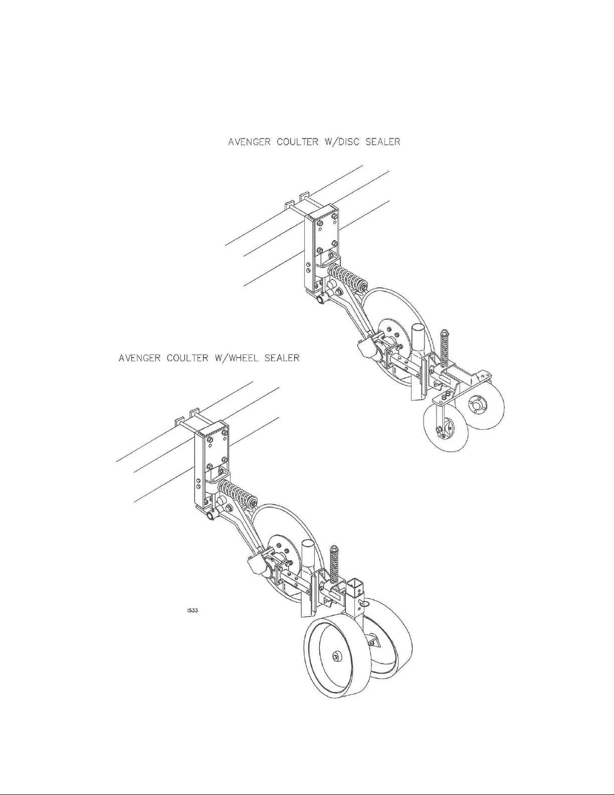
OPTIONAL EQUIPMENT
Attach optional sealing equipment to the Avenger at the sealer mount bracket using hardware that is
supplied with the sealing equipment kit. For proper operation of the closing system in field adjustments will
be required initially and as soil conditions change.
18
Page 19

OPERATION
Yetter Model 2986 25” coulter is designed to inject liquid material 4”-8” deep below the
surface. Depth of operation of the coulter will vary depending on your particular
application.
IMPORTANT: For proper operation, the toolbar frame must operate level (for and aft) and at the
correct height, usually 22” – 25” while in operation.
In hard no-till conditions the desired operating depth may not be possible. Tighten the
spring pressure adjustment to obtain maximum depth if spring is flexing rather than lower
the toolbar frame below the 22” minimum recommended setting.
Toolbar weight may limit operating depth in hard soil conditions, ballast weight can be
added to the toolbar frame. Example, 200 lb. per coulter may be required to get desired
depth and obtain toolbar frame height of 22”-25”.
Coulter operating depth is affected by spring tension, toolbar height, levelness of toolbar
and soil conditions. As soil conditions change, toolbar settings and coulter adjustments
will need to be changed as well.
Toolbar gauge wheel kits are recommended for use with the Avenger coulter because of
toolbar frame height being very critical.
1. Set/mount coulter blades to run vertical to the soil. Operation depth and blade wear can
be affected if coulter is mounted crooked or if toolbar is not level side to side.
2. After a few hours use, check all bolts and setscrews for tightness and proper torque
settings.
3. After a day of use (10-12 hours), check coulter hubs for loose bearings. There should
be no end play in the hub bearings to allow it to wobble. If necessary, remove hub cap
and cotter pin, adjust slotted nut to remove wobble, recommended torque of 13 ft/lbs,
re-insert cotter pin and replace hub cap. If the wobble or looseness can not be
corrected, the bearings, cups and seal will need to be replaced. DO NOT RE-USE
WORN OR DAMAGED PARTS.
19
Page 20

OPERATION
TOOLBAR FRAME HEIGHT ADJUSTMENT
Figure A. The toolbar frames are equally 22”-25” off the ground. To ensure that frame heights are equal, it
is important that measurements are taken. The tube frames should be parallel with the soil surface.
Figure B. The hitch is set too low while the toolbar frames are not equal distance from the soil surface.
NOTE: The illustrations are intended to show that the settings are critical. Tool frame levelness and
height adjustment are very important settings for correct performance of the coulters.
20
Page 21
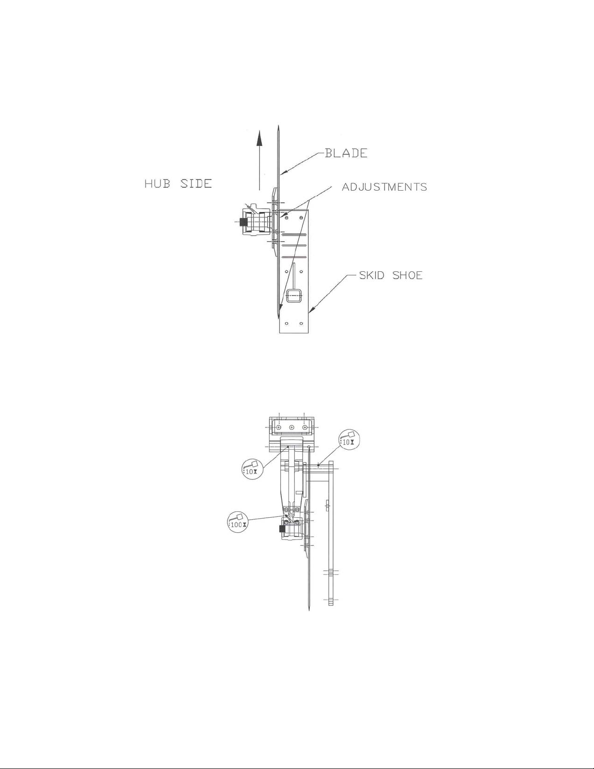
OPERATION INSTRUCTIONS
RIGHT HAND ASSEMBLY
DIRECTION OF TRAVEL
1. Adjust the shoe the same front and back.
2. Start with no gap between the blade and shoe.
3. Set the shoe just touching the blade.
OPERATION MAINTENANCE
LUBRICATION: Each coulter is equipped with (3) grease zerks. To ensure longevity and reliability of
the coulter, the recommended lubrication schedule should be followed using general purpose grease at
hourly intervals indicated on symbol.
21
Page 22

OPERATION MAINTENANCE
BEARING ADJUSTMENT:
1. Raise the toolbar until the blade is clear of the ground. Place a safety stand under the toolbar.
Remove the blade. Remove the hub cap, cotter pin, slotted nut, washer and spacer from the
spindle shaft assembly.
2. Pull the coulter spindle shaft assembly from the hub. Remove bearing cones and seal.
3. Wash the old grease from the hub, bearing cups, coulter spindle shaft, seal and bearing cones.
Inspect the condition of bearing cups, cones and seal. Replace if necessary.
4. Apply #2 multi-purpose lithium grease on each bearing. Make sure the space around each roller is
filled. Lubricate the bearing cups.
5. Position the bearing in the cup and install the seal. Lubricate the seal lips and proceed with reassembly of the removed parts including the blade. Blade bolt torque is 90 to 96 ft/lbs.
6. Tighten the slotted nut to 10 to 15 ft/lbs. or until a definite drag is felt when the blade is turned by
hand. Back off the nut one slot position to line up the cotter pin hole with a slot. Secure the nut with
a new cotter pin.
SCRAPER WEAR:
The lower portion of the scraper and tube are subject to wear during operation. The rate of wear will
depend on a variety of factors and in abrasive hard soil conditions the wear will be more rapid.
NOTE: In certain areas, replacement scrapers should be kept in stock, replacing worn scrapers as
needed.
22
Page 23

MAINTENANCE
BEARING ASSEMBLY AND LUBRICATION
Practice Safety
Understand and practice safe service procedures before doing work. Follow ALL the
operating, maintenance and safety information in the equipment operator manual. Clear
the area of bystanders, especially small children, when performing any maintenance or
adjustments. Keep work area clean and dry. Use adequate lighting for the job. Use only
tools, jacks and hoists of sufficient capacity for the job.
Never lubricate, service, or adjust machine while it is moving. Keep hands, feet, and
clothing from power-driven moving and rotating parts. Disengage all power and operate
controls to relieve pressure. Lower equipment to the ground and stop the engine.
Remove the key. Wait for all moving parts to stop before servicing, adjusting, repairing or
unplugging.
Securely support any machine elements with blocks or safety stands that must be raised
for service work.
Keep all parts in good condition and properly installed. Fix damaged equipment
immediately. Replace worn or broken parts. Remove any buildup of grease, oil, or debris.
Make sure all guards are in place and properly secured when maintenance work is
completed.
Assembly
23
Page 24

MAINTENANCE
NOTE: Be certain to align the grease fitting with the slot in the wheel and the hubcap so
that the grease can flow freely.
24
Page 25

MAINTENANCE
Grease must fill this
Hubcap cavity.
25
Page 26

MAINTENANCE
Lubrication
CAUTION: To help prevent serious injury or death to you or others caused by
unexpected movement, service machine on a level surface. Lower machine to
ground or sufficiently lock or block raised machine before servicing. If machine
is connected to tractor, engage parking brake and place transmission in
"PARK", shut off engine and remove key. If machine is detached from tractor,
block wheels and use shop stands to prevent movement.
CAUTION: Do not clean, lubricate, or adjust machine while in motion.
Use grease based on NLGI consistency numbers and the expected air temperature
range during the service interval.
Use a multi-purpose lithium, water resistant, moderate speed, and NLGI grade #2
grease.
Other greases may be used if they meet the following NLGI Performance
Classification: GC-LB
IMPORTANT: Some types of grease thickener are not compatible with others.
Consult your grease supplier before mixing different types of grease.
Alternative Lubricants
Conditions in certain geographical areas may require special lubricants and lubrication
practices which do not appear in the operator's manual. If there are any questions,
consult Yetter Manufacturing Co. to obtain latest information and recommendation.
PART # DESCRIPTION OUNCES OF GREASE
2967-404 13” TAPER TOOTH R.M. WHEEL 1.12 OZ
2967-602 13” SHARK TOOTH R.M. WHEEL 1.12 OZ
2967-186 FLOATER WHEEL KIT W/R.M. WHEEL 2.08 OZ
2967-596 HEAVY DUTY OR BEVEL R.M. WHEEL
W/ FLOATER WHEEL KIT
2.40 OZ
Storing Lubricants
Your machine can operate at top efficiency only if clean lubricants are used.
Use clean containers to handle all lubricants.
Store them in an area protected from dust, moisture and other contaminants.
26
Page 27

MAINTENANCE
Lubrication Symbols
Lubricate with grease at hourly interval indicated on symbol.
Lubrication Intervals
IMPORTANT: The recommended service intervals are based on normal conditions;
severe or unusual conditions may require more frequent lubrication.
Perform each lubrication and service procedure at the beginning and end of each
season.
Clean grease fittings before using grease gun, to avoid injecting dirt and grit into the
bearing. Replace any lost or broken fittings immediately. If a fitting fails to take grease,
remove and clean thoroughly, replace fitting if necessary. Also check for failure of
adjoining parts.
BEARING REPLACEMENT INSTALLATION
1. When assembling the spoke wheels, bearing assembly and hubcap, be sure to
align the grease transfer hole in the spoke wheel with the groove in the hubcap
and hole in the hub to allow grease passage.
2. Assemble the wheels, hubs and caps
3. Grease the wheel/hub/bearing assembly.
27
Page 28

MAINTENANCE
Storing the Equipment
Store the machine in an area away from human activity
Store machine in RAISED position.
Install service locks on all wheel cylinders.
At the end of the season, the machine should be thoroughly inspected and prepared for
storage. Repair or replace any worn or damaged components to prevent down time at the
start of the next season. Store machine under cover with all parts in operating condition.
• Clean machine thoroughly to remove all dirt, debris and crop residue, which would
hold moisture and cause rusting.
• Inspect machine for worn or broken parts. See your Yetter Farm Equipment dealer
during the off-season so that parts or service can be acquired when machine is not
needed in the field.
• Lubricate bearings as outlined in the Lubrication section
• Paint all parts which are chipped or worn and require repainting.
• Store machine in a clean, dry place with the planting unit out of the sun.
• If the machine cannot be stored inside, cover with a waterproof tarpaulin and tie
securely in place.
Do not allow children to play on or around the machine
28
Page 29

PARTS IDENTIFICATION
Right Hand Assembly Shown
29
Page 30

PARTS IDENTIFICATION
30
Page 31

PARTS IDENTIFICATION
KEY QTY. PART NUMBER DESCRIPTION
1 1 2550-065 HUB CAP, WILTON #909912-1
2 1 2986-329 MACH. CASTLE NUT 1 ¼-12
3 1 2531-124 3/16 X 2 COTTER PIN
4 1 2526-562 1 17/64 ID X 2 ¼ OD X 10 GA. MB BLK
5 2 2550-057 BEARING, KOYO #2788R
6 1 2986-403 MOUNTING HUB
1 2533-110 ¼-28 ZERK STRAIGHT SELF-TAP
2 2550-056 CUP, KOYO #2729
7 1 2550-058 SEAL, CR #17699
8 1 2986-402 25” COULTER SPINDLE
NOTE: Detail #2 is to be torqued to between 12 and 15 ft/lbs.
31
Page 32
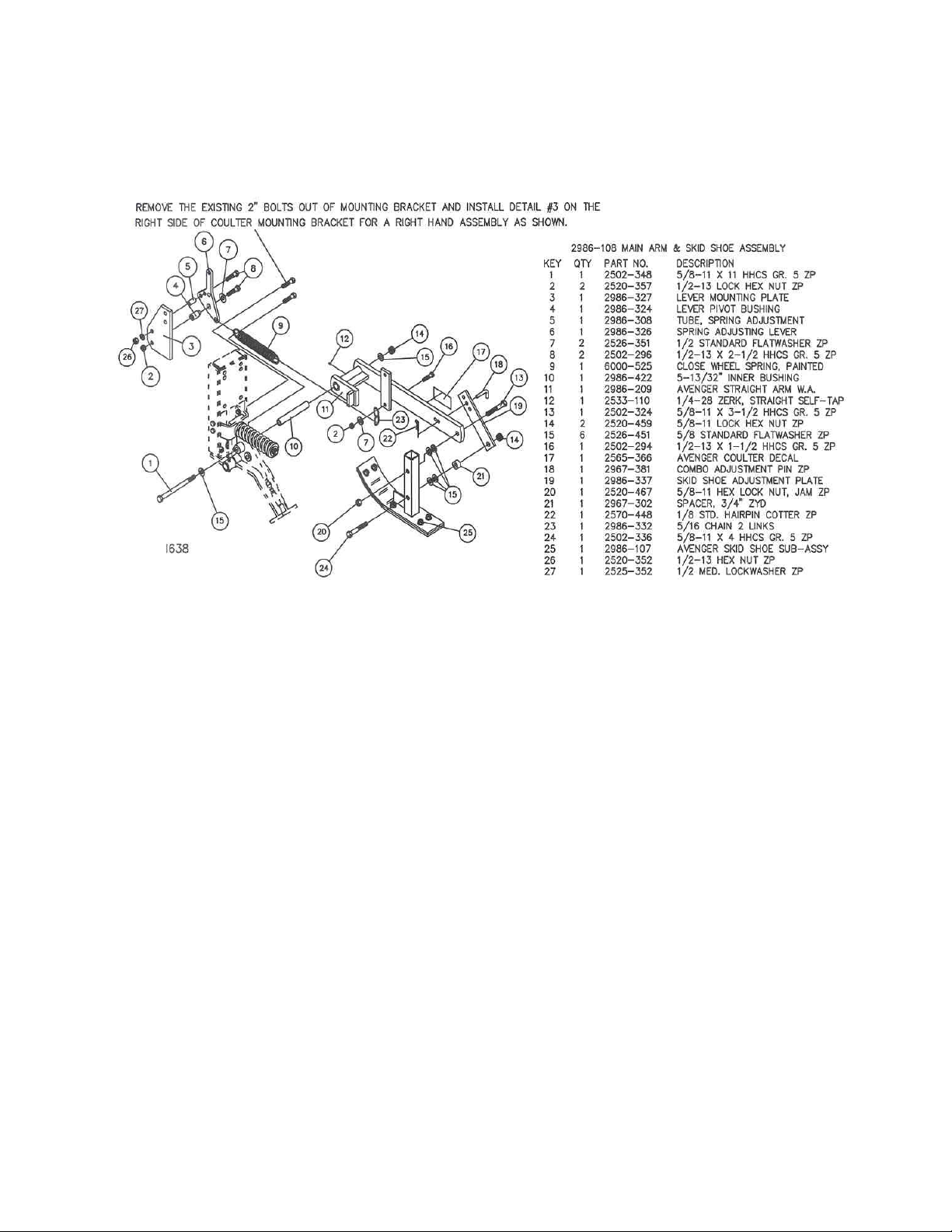
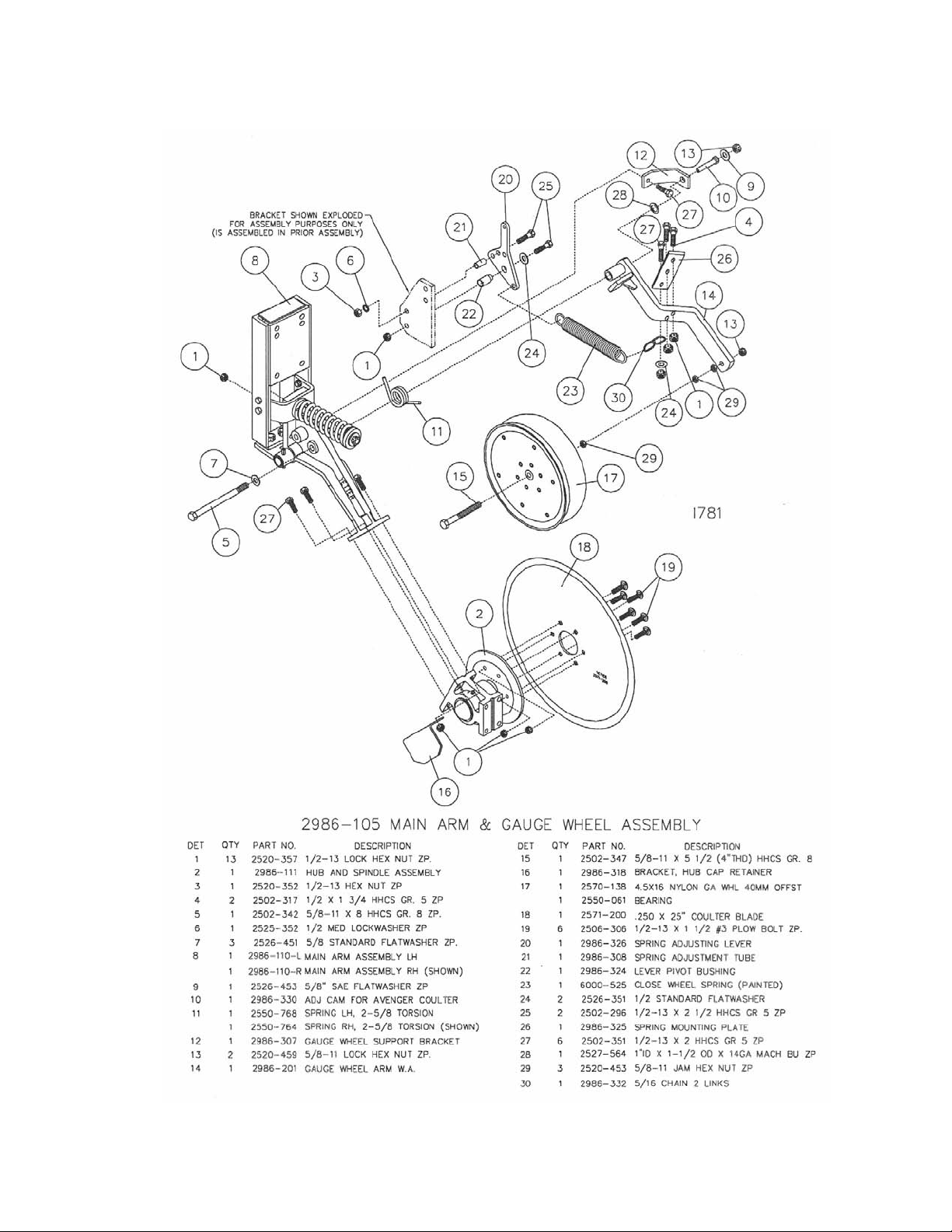
PARTS IDENTIFICATION
2986-108 MAIN ARM & SKID SHOE ASSEMBLY
KEY QTY. PART NUMBER DESCRIPTION
1 1 2502-348 5/8-11 X 11 HHCS GR 5 ZYD
2 2 2520-357 ½-13 HEX LOCK NUT ZYD
3 1 2986-327 LEVER MOUNTING PLATE
4 1 2986-324 LEVER PIVOT BUSHING
5 1 2986-308 TUBE, SPRING ADJUSTMENT
6 1 2986-326 SPRING ADJUSTING LEVER
7 2 2526-351 ½ STANDARD FLAT WASHER ZYD
8 2 2502-296 ½-13 X 2 ½ HHCS GR 5 ZYD
9 1 6000-525 CLOSE WHEEL SPRING, PAINTED
10 1 2986-422 5 13/32” INNER BUSHING
11 1 2986-209 AVENGER STRAIGHT ARM W .A.
12 1 2533-110 ¼-28 ZERK, STRAIGHT SEFL-TAP
13 1 2502-324 5/8-11 X 3 ½ HHCS GR 5 ZYD
14 2 2520-459 5/8-11 HEX LOCK NUT ZYD
15 6 2526-451 5/8 STANDARD FLAT W ASHER ZYD
16 1 2502-294 ½-13 X 1 ½ HHCS GR 5 ZYD
17 1 2565-366 AVENGER COULTER DECAL
18 1 2967-381 COMBO ADJUSTMENT PIN ZYD
19 1 2986-337 SKID SHOE ADJUSTMENT PLATE
20 1 2520-467 5/8-11 HEX LOCK JAM NUT ZYD
21 1 2967-302 SPACER, ¾ ZYD
22 1 2570-448 1/8 STD. HAIRPIN COTTER ZYD
23 1 2986-332 5/16 CHAIN 2 LINKS
24 1 2502-336 5/8-11 X 4 HHCS GR 5 ZYD
25 1 2986-208 AVENGER SKID SHOE W .A.
26 1 2520-352 ½-13 HEX NUT ZYD
27 1 2525-352 ½ MED. LOCK WASHER ZYD
28 1 2986-340 4 1/4" POLY SKID SHOE
29 6 N10213 5/16-18 HEX FLANGE SERRATED NUT
30 6 2505-206 5/16-16 X 1 CAR BOLT GR 5 ZYD
32
Page 33
PARTS IDENTIFICATION
FOR COULTERS BUILT PRIOR TO 6-01-01
33
Page 34
PARTS IDENTIFICATION
FOR COULTERS BUILT PRIOR TO 6-01-01
2986-104 AVENGER SKID SHOE
Key Qty. Part No. Description
1 1 2502-324 5/8-11 x 3-1/2 HHCS Gr. 5 ZP
2 1 2965-305 Pin, Furrowing Attachment ZYD
3 1 2986-337 Skid Shoe Adjustment Plate
4 3 2520-453 5/8-11 Jam Hex Nut ZP
5 2 2526-451 5/8 Std. Flat washer ZP
6 1 2570-448 1/8 Std. Hairpin Cotter ZP
7 1 2520-467 5/8-11 Hex Locknut, Jam ZP
8 1 2502-347 5/8-11 x 5-1/2 HHCS Gr. 8, 4”Thd.
9 1 2520-459 5/8-11 Lock Hex Nut ZP
10 6 N10213 5/16-18 Hex Flange Serrated Nut
11 1 2986-208 Avenger Skid Shoe W.A.
12 1 2986-340 4-1/4” Poly Skid Shoe
13 6 2505-206 5/16-18 x 1 Car. Bolt Gr. 5 ZP
34
Page 35
PARTS IDENTIFICATION
35
Page 36

PARTS IDENTIFICATION
36
Page 37

PARTS IDENTIFICATION
37
Page 38

PARTS IDENTIFICATION
38
Page 39

TROUBLESHOOTING
Problem
25" coulter blade creates soil disruption.
Slot cut by 25" coulter blade fills and overflows
with material.
Inadequate 25" coulter blade depth.
Slot made by 25" blade remains open.
Optional sealer forces liquid out of trench.
Inadequate slot being made by 25" coulter blade.
Coulter plugging.
Breakage or excessive damage to blades.
Solution
Add optional skid shoe kit 2986-108
Increase skid shoe spring tension.
Make sure maximum coulter operating depth is
reached (8”).
Cut back volume of the material which is being
applied.
Increase ground speed.
Tighten down pressure spring.
Add 2550-771 10” poly helper spring.
Add additional ballast. Example: 200# per
coulter. Operate toolbar height 22”-25”
Install optional disc sealer 12” 2920-012, 16”
2930-012, 2920-016, 2920-016-N, or optional
wheel sealer 2984-009.
Decrease disc sealer spring tension.
Readjust blade angle.
Adjust disc arm side to side to space disc blade
further from trench.
Increase depth of the 25” blade.
Sharpen or replace 25” coulter blade.
Adjust scraper to touch flat against the blade.
Replace scraper
Avoid turning with blades in the ground.
Avoid operating in frozen ground.
Reduce speed in rocks or other adverse
conditions.
39
Page 40

Our name
Is getting known
Just a few years ago, Yetter products were sold primarily
to the Midwest only. Then we embarked on a program of
expansion and moved into the East, the South, the West and
now north into Canada. We’re even getting orders from as
far away as Australia and Africa.
So, when you buy Yetter products . . .you’re buying a name
that’s recognized. A name that’s known and respected. A name
that’s become a part of American agriculture and has become
synonymous with quality and satisfaction in the field of
conservation tillage.
Thank you.
YETTER MANUFACTURING CO.
Colchester, IL 62326-0358 309/776-4111
Toll Free 800/447-5777
Fax 309/776-3222
Website: www.yetterco.com
E-mail: info@yetterco.com
2565-419_REV_E
07/13
40
 Loading...