

Yetter 8500-027, 8500-032, 8500-038, 8500-043, 8500-048 Owner's Manual
OWNER’S MANUAL
8500 SERIES HEAD CART
ALL MODELS
2565-799_B 02/2019
Yetter Manufacturing
Founded 1930
Colchester, IL 62326
Call: (309)776-4111
Fax: (309)776-3222
Website: www.yetterco.com
Email: info@yetterco.com

FOREWORD
WARRANTY
You’ve just joined an exclusive but rapidly
growing club. For our part, we want to
welcome you to the group and thank you for
buying a Yetter product.
We hope your new Yetter products will help
you achieve two goals: increase your
productivity and increase your efficiency so
that you may generate more profit.
This SAFETY ALERT SYMBOL
indicates important safety
messages in the manual. When
you see this symbol, be alert to the
possibility of PERSONAL INJURY and
carefully read the message that follows.
The word NOTE is used to convey
information that is out of context with the
manual text. It contains special information
such as specifications, techniques and
reference information of a supplementary
nature.
The word IMPORTANT is used in the text
when immediate danger will occur to the
machine due to improper technique or
operation.
It is the responsibility of the user to read the
owner’s manual, comply with safe and
correct operating procedure, and to
lubricate and maintain the product
according to the information listed in the
owner’s manual.
The user is responsible for inspecting their
machine and for having parts repaired or
replaced when it is damaged or worn.
Continued use of a damaged or worn part
can cause injury or more extensive damage
to the machine.
If you have any questions regarding the
information given in this manual, consult
your local Yetter dealer or contact:
Yetter Manufacturing Co.
(309)776-4111
(800)447-5777
Website: www.yetterco.com
Email: info@yetterco.com
Yetter Manufacturing warrants all products manufactured and sold by it against defects
in material. This warry being expressly limited to replacement at the factory of such parts
or products that appear to be defective after inspection. The warranty does not obligate
Yetter Manufacturing to bear the cost of labor in replacement of parts. It is the policy of
the Company to make improvements without incurring obligations to add them to any
unit sold prior. No warranty is made, or authorized to be made, other than herein set
forth. This warranty is in effect for one year after purchase.
Dealer:__________________________
Yetter Manufacturing warrants its own products and cannot be held responsible
for damages to equipment on which they are mounted.
2

TABLE OF CONTENTS
SAFETY .................................................................................................. 4-5
GENERAL INFORMATION ..................................................................... 6-8
BOLT TORQUE .......................................................................................... 9
SET-UP ............................................................................................... 10-11
OPERATION ....................................................................................... 12-13
MAINTENANCE ....................................................................................... 14
PART IDENTIFICATION ..................................................................... 15-34
3

SAFETY INFORMATION
BE ALERT!
YOUR SAFETY IS INVOLVED
It is the responsibility of the owner, operator, or supervisor to know and instruct
everyone using this machine at the time of initial assignment and at least annually
thereafter, of the proper operation, precautions, and work hazard which exist in the
operation of the machine in accordance with OSHA regulations.
SAFETY IS NO ACCIDENT
The following safety instructions combines with common sense will save your
equipment from needless damage and the operator from unnecessary exposure
to personal hazard. Pay special attention to the caution notes in the text. Review
this manual each year and with new and experience operators.
1. Read and understand the operator’s manual before operating this machine.
Failure to do so is considered a misuse of the equipment.
2. Make sure equipment is secure before use.
3. Always keep children away from equipment while in operation.
4. Make sure everyone that is not directly involved with the operation is clear of the
work area before use.
5. Be sure all safety devices, shield, and guards are in place and functional before
beginning operation
6. Shut off all power to the unit prior to adjustment, servicing, or cleaning.
7. Keep hands, feet, and clothing away from moving parts. It is a good idea to
remove all jewelry before starting the operation.
8. Visually inspect the machine periodically during operation for signs of excessive
vibration, loose fasteners, and unusual noises.
4

SAFETY INFORMATION
During Operation
• Regulate speed to field conditions. Maintain complete control at all times.
• Never lubricate equipment when in operation.
• Use extreme care when operating close to ditches, fences, or on hillsides.
• Do no leave towing vehicle unattended with engine running.
• Do no adjust the transporter with the head positioned over the unit.
Before Operation
• Secure the transport chains to towing vehicle before transporting. DO NOT
transport without the chains.
• Check for proper function of all available transport lights. Make sure that all
reflectors are clean and in place on the machine.
• This implement may not be equipped with brakes. Ensure that the towing vehicle
has adequate weight and braking capacity to tow this unit.
• Before transporting, secure the head with straps. Replace damaged or worn
straps, and avoid putting straps over rough or sharp surfaces. Use appropriate
number and capacity rating.
During Transport
• Comply with state and local laws governing highway safety when moving
machinery.
• Use transport lights as required by local laws to adequately warn operators of
other vehicles.
• Use good judgement when transporting equipment on highways. Regulate speed
to road conditions and maintain complete control.
• Slow down before making sharp turns to avoid tipping. Drive slowly over rough
ground and side slops.
• It is probable that this implement is taller, wider, and longer than the towing
vehicle. Become aware of and avoid all obstacles and hazards in the travel path
of the equipment such as power lines, ditches, etc.
5
GENERAL INFORMATION
Model No.
Description
Est. Wt.
Model No.
Description
Est. Wt.
Model No.
Description
Est. Wt.
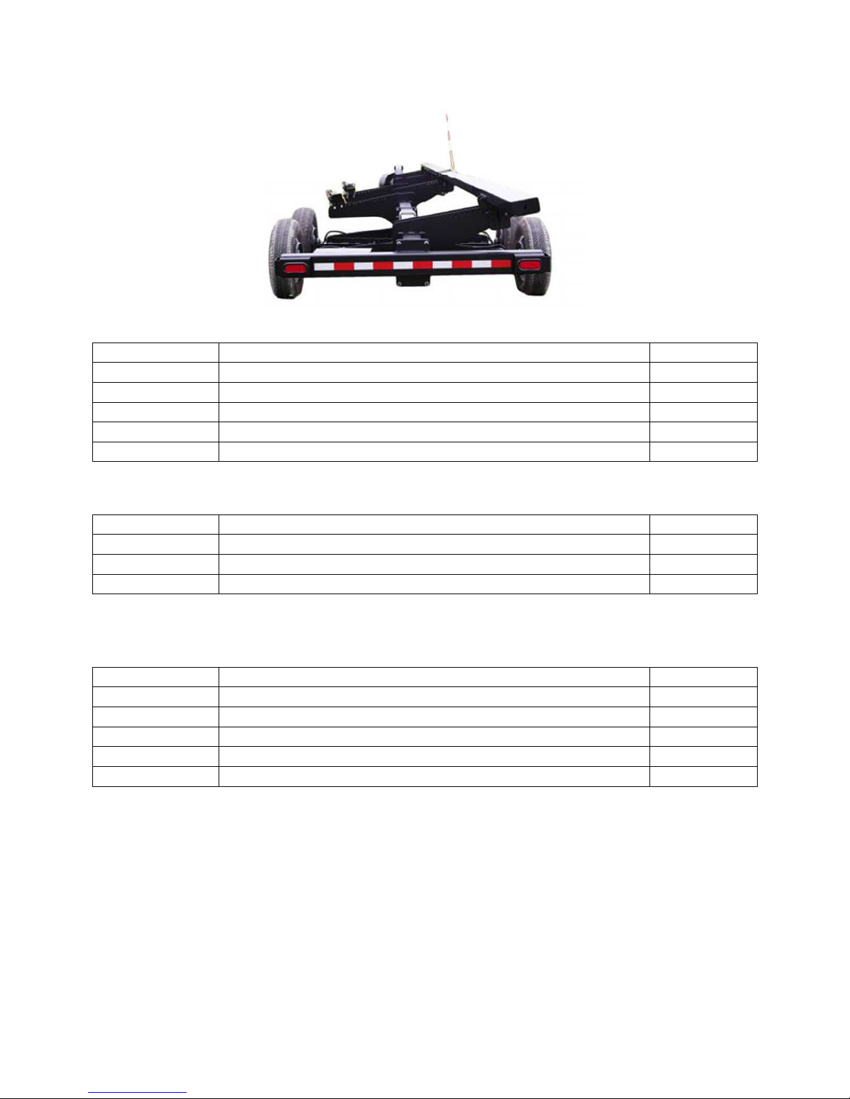
8500 Series Head Cart Trailers
8500-027 27’ Head Cart 3260 lbs
8500-032 32’ Head Cart 4103 lbs
8500-038 38’ Head Cart 4358 lbs
8500-043 43’ Head Cart 4741 lbs
8500-048 48’ Head Cart 4970 lbs
Optional Equipment
8500-001 Marker Pole 3 lbs
8500-144 Ball Hitch 2-5/16” 10 lbs
8500-166 Drop Pin Hitch 14 lbs
Service Kits
8500-120 Rear Bearing and Drum Replacement Kit (1 Per Wheel) 40 lbs
8500-121 Lugnut and Stud Replacement Kit (1 Per Wheel) 4 lbs
8500-122 Front and Rear Bearing Replacement Kit (1 Per Wheel) 7 lbs
8500-123 Brake Replacement Kit (1 Per Axle) 10 lbs
8500-124 Front Bearing and Hub Replacement Kit (1 Per Wheel) 26 lbs
6

GENERAL INFORMATION
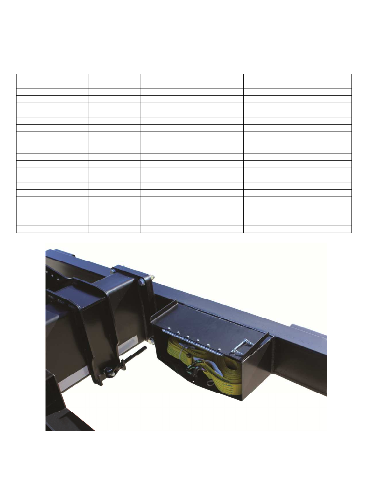
8500 Series Head Cart Trailers
• Central beam design with adjustable truss supports
• Spare cutter bar storage
• Dual 12” rest brackets to fit any header platform with tool-
less adjustments
• Drum brakes on rear axle(s)
• Front and rear torsion axles providing a smooth ride
• Molded front fenders protecting head and truck from road
debris
• Tongue rotates around to main beam for easy winter storage
and shipment
• 24” of telescoping hitch adjustment
• Dual safety chains with standard clevis hitch. Options for
drop-pin and ball hitch attachments
• LED lights and seven pin bladed receptacle for standard
towing vehicles
• Full length DOT reflective tape
• Tool box – 17 ¾” x 8” x 7”
• Full width rear light support brackets
• Durable black powder coat finish
• Made in the USA, manufactured and shipped from Macomb,
IL
7
GENERAL INFORMATION
8500
-
027 8500
-
032 8500
-
038 8500
-
043 8500
-
048
Overall Length (in)
Overall Width (in)
Overall Height (in)
Unloaded Weight (lb)
Max Gross Weight (lb)
Max Usable Weight (lb)
Max Drawbar Pull (lb)
Chassis Style
Axle Configuration
Axle Stud Pattern
Tire Size
Max Tire PSI
Electric Brakes
Over Run Brakes
Cutter Bar Storage
Lights
Front Fenders
Accessory Box
License Plate Lights
Rear Fenders
Marker Pole Kit
8500 Series Head Cart Trailers
Technical Specifications
429 489 561 621 681
102 102 102 102 102
44 44 44 44 44
3260 4103 4391 4741 4970
12000 18000 18000 18000 18000
8740 13897 13609 13259 13030
17600 17600 17600 17600 17600
Single Beam Single Beam Single Beam Single Beam Single Beam
Single Tandem Tandem Tandem Tandem
8 x 6.5” BC 8 x 6.5” BC 8 x 6.5” BC 8 x 6.5” BC 8 x 6.5” BC
8-14.5 LT 14
Standard
Standard
Standard
Standard
Standard
Standard
Wire Leads Only Wire Leads Only Wire Leads Only Wire Leads Only Wire Leads Only
Optional
Optional
PLY
8-14.5 LT 14
65 65 65 65 65
Standard
Standard
Standard
Standard
Standard
Standard
Optional
Optional
PLY
8-14.5 LT 14
Standard
Standard
Standard
Standard
Standard
Standard
Optional
Optional
PLY
8-14.5 LT 14
Standard
Standard
Standard
Standard
Standard
Standard
Optional
Optional
PLY
8-14.5 LT 14
Standard
Standard
Standard
Standard
Standard
Standard
Optional
Optional
PLY
8
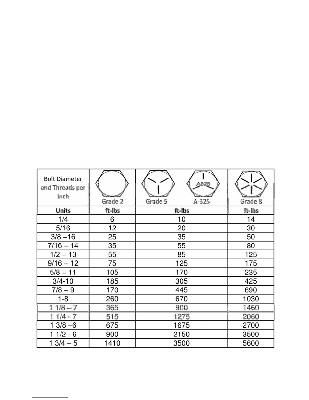
BOLT TORQUE
Important: Over tightening hardware can cause as much damage as under tightening.
Tightening hardware beyond the recommended range can reduce it shock load
capacity.
All hardware used on the 8500 Series Head Cart is Grade 5 unless otherwise specified.
If hardware must be replaced, be sure to replace it with hardware of equal size,
strength, and thread type.
The chart below is a guide for proper torque. Use it unless a specified torque
value is given elsewhere in the manual.
Torque is the force you apply to the wrench handle times the length of the handle.
Use a torque wrench wherever possible
The following table shows torque in ft-lbs for coarse thread hardware.
9

SET UP INSTRUCTIONS
1
2
3
4 5
6
7 8
6.5” BC
Tires and Wheels
1. Using a safe lifting device and jack stands rated at a minimum of 2500 lbs, raise
the frame at least 16 ½” high
2. Install wheels and tires onto the axles and secure with provided lug nuts. Refer to
the table below for torque sequence and value.
• Start all lug nuts by hand to prevent cross threading
• Tighten nuts in the sequence shown below
• Lug nuts should be torqued before first road use and after each wheel
removal. Check and re-torque after the first 50 miles. A periodic check
during regular service is recommended.
Wheel Size Stud Size 1st Stage 2nd Stage 3rd Stage
14.5 X 7 9/16” 25 lb-ft 70 lb-ft 130 lb-ft
10
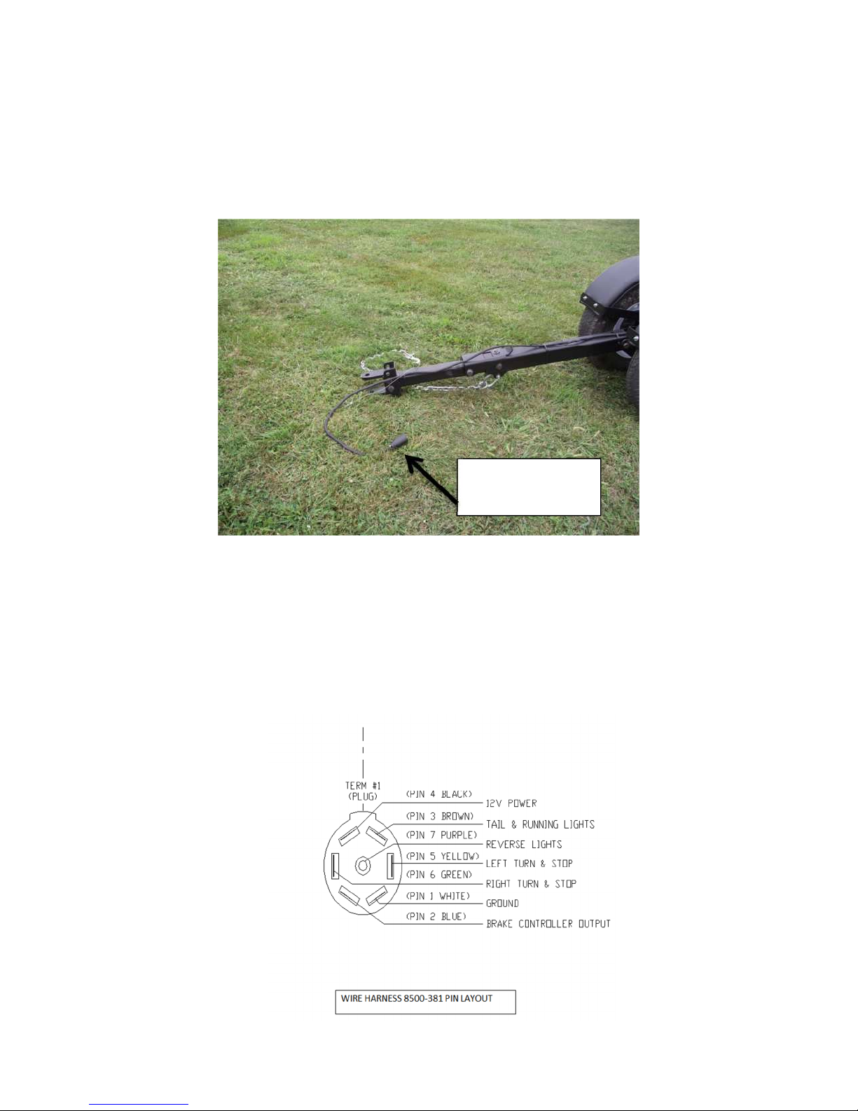
SET UP INSTRUCTIONS
ATTACH TO
Test Lights
Make sure no wires are pinched or cut during installation.
Keep all wires concealed to prevent them from getting caught on obstructions.
Attach 8500 Head Cart and wiring harness to tow vehicle to test the lights.
Check the following:
• Tail lights
• Brake lights
• Left and right turn signals with and without brakes applied
TOW VEHICLE
Note: If any of the light tests fail, check wiring harness on tow vehicle for proper
wiring.
11

OPERATION
Hitching
1. Position towing vehicle in front of header transport. Lift tongue latch handle and
extended inner tongue extension enough to attach to vehicle drawbar using a ¾”
minimum diameter hitch pin and lock in place. Back-up towing vehicle to re-latch
tongue.
2. Cross transport chains and connect to towing vehicle.
Note: Before hitching the header transport to any vehicle drawbar, be sure the pin
hole is located close enough to the rear of the vehicle drawbar to allow the
header transport tongue clevis to swing 90 degrees right or left of the centerline
without interference.
Note: When hitching, be sure not to pinch wire harness. Position the wire harness
away from all pinch points and any areas that may wear the harness.
CAUTION: BE SURE TRANSPORT TONGUE IS LATCHED
BEFORE TRANSPORTING, OTHERWISE JARRING COULD
OCCUR WHEN STOPPING UNIT, CAUSING A SUDDEN SHIFT OF
LOAD.
CAUTION: ALWAYS USE TRANSPORT CHAINS WHEN
TRANSPORTING IMPLEMENTS. FAILURE TO USE TRANSPORT
CHAIN COULD CAUSE PERSONAL INJURY OR DAMAGE IF
IMPLEMENT BECOMES DISENGAGED.
12
 Loading...