

Page 1
INSTRUCTION MANUAL
AND PARTS CATALOG
V-CLOSE WHEEL KIT
CNH ROW UNIT
YETTER MANUFACTURING CO.
FOUNDED 1930
Colchester, IL 62326-0358
Toll free: 800/447-5777
309/776-3222 (Fax)
Website: www.yetterco.com
E-mail: info@yetterco.com
Page 2

FOREWORD
You’ve just joined an exclusive but rapidly
growing club.
For our part, we want to welcome you to the
group and thank you for buying a Yetter Product.
We hope your new Yetter implement will help
you achieve both increased productivity and
increased efficiency so that you may generate
more profit. This operator’s manual has been
designed into six major sections.
Foreword, Safety Precautions, assembly
instructions, Operation, parts identification and
troubleshooting.
It is important the owner/operator knows the
implement model number. Write the model
number in the space provided and use it in all
correspondence when referring to the
implement.
Throughout the manual references may be
made to left side and right side. These terms
are used as viewed from the operator’s seat
facing the front of the tractor.
This SAFETY ALERT SYMBOL
indicates important safety messages in
the manual. When you see this
be alert to the possibility of PERSONAL INJURY
and carefully read the message that follows.
The word NOTE is used to convey information
that is out of context with the manual text. It
contains special information such as
specifications, techniques, reference information
Yetter Manufacturing warrants all products manufactured and sold by it against defects in material. This
warranty being expressly limited to replacement at the factory of such parts or products as will appear to be
defective after inspection. This warranty does not obligate the Company to bear cost of labor in replacement
of parts. It is the policy of the company to make improvements without incurring obligations to add them to
any unit already sold. No warranty is made or authorized to be made, other than herein set forth. This
warranty is in effect for one year after purchase.
Yetter Manufacturing warrants its own products only and cannot be responsible for damage to
equipment on which it is mounted.
symbol, be alert to the possibility of
WARRANTY POLICY
Model Number:_________________________
Dealer :___________________
and other information of a supplementary nature.
The word IMPORTANT is used in the text when
immediate damage will occur to the machine
due to improper technique or operation.
Important will apply to the same information as
specified by note only of an immediate and
urgent nature.
It is the responsibility of the user to read the
operator’s manual and comply with the safe and
correct operating procedure and to lubricate and
maintain the product according to the
maintenance schedule in the operator’s manual.
The user is responsible for inspecting his
machine and for having parts repaired or
replaced when continued use of the product
would cause damage or excessive wear to the
other parts.
It is the user’s responsibility to deliver his
machine to the Yetter dealer who sold him the
product for service or replacement of defective
parts that are covered by the warranty policy.
If you are unable to understand or
follow the instructions provided in the
publication, consult you local Yetter
dealer or contact:
YETTER MANUFACTURING CO.
309/776-4111
800/447-5777
309/776-3222 (FAX)
Website: www.yetterco.com
E-mail: info@yetterco.com
2
Page 3

SAFETY
A brief description of signal words that may be used in this manual:
CAUTION: Used as a general reminder of good safety practices or to direct attention to unsafe practices.
WARNING: Denotes a specific potential hazard.
DANGER: Denotes the most serious specific potential hazard.
SAFETY PRECAUTIONS
You can make your farm a safer place to live and work if you observe the safety precautions given. Study
these precautions carefully and insist that those working with you and for you follow them.
Finally, remember this: an accident is usually caused by someone’s carelessness, neglect or oversight.
WARNING
Never clean, lubricate or adjust a machine that is in motion. Always lower or block the implement before
performing service.
If the machine must be serviced in the raised position, jack or block it up to prevent it from accidentally
falling and injuring someone.
Do not allow riders on the tractor or implement.
Use speeds and caution dictated by the terrain being traversed. Do not operate on any slope steep enough
to cause tipping or loss of control.
Be sure all personnel are clear of the immediate area before operating.
Read and understand the operator’s manual and require all other persons who will operate the equipment to
do the same.
Be familiar with all tractor and implement controls and be prepared to stop engine and implements quickly in
an emergency.
CAUTION
Consult your implement and tractor operator’s manual for correct and safe operating practices.
Beware of towed implement width and allow safe clearance.
FAILURE TO HEED MAY RESULT IN PERSONAL INJURY OR DEATH.
3
Page 4
ASSEMBLY INSTRUCTIONS
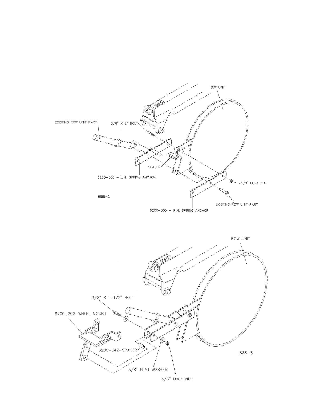
STEP 1. Remove the covering disc and the press wheel from the
row unit.
STEP 2. Attach the 6200-306 L.H. spring anchor and 6200-305 R.H. spring anchor to
the row unit using a 3/8” x 2” bolt, spacer and lock nut.
STEP 3. Attach the 6200-202 – v-closing wheel mount to the spring anchor straps using
a 3/8” x 1-1/2” bolt, 3/8” flat washer, spacer, 3/8” flat washer and lock nut.
4
Page 5

ASSEMBLY INSTRUCTIONS
STEP 4. Insert the 6000-524 – close wheel lever into the 6000-247 close
wheel arm, install the spring onto the close wheel lever and attach the
close wheel lever to the wheel arm using a 5/16” x 1-1/2” bolt and lock nut.
STEP 5. First, hook the spring onto the 6200-202 – close wheel mount
then attach the close wheel arm assembly to the left hand side of the
6200-202 close wheel mount and the row unit using the ½” x 1” bolt, 6200341 – link and lock nut. Insert the 6000-523 – eccentric bushing into the
close wheel arm and connect the close wheel arm to the 6200-341 - link
and 6200-202 – wheel mount using a ½” x 2-1/2” bolt, ½” flat washer and
lock nut.
5
Page 6

ASSEMBLY INSTRUCTIONS
STEP 6. Attach the close wheel arm assembly to the right hand side of
the 6200-202 – close wheel mount and the row unit by inserting the 6000523 – eccentric bushing into the close wheel arm assembly and securing
with the ½” x 2-1/2” bolt, link, ½” flat washer and lock nut. Attach the link
to the close wheel bracket using a ½” x 1” bolt and lock nut.
STEP 7. Attach the wheels to the 6000-247 arm using a 5/8” x 4” bolt, flat
washer, bushing, spacer and 5/8” lock nut.
NOTE: In certain conditions, seed to soil contact and residue flow can be
improved by spacing closing wheels further apart and or staggering them.
To space closing wheels further apart place the spacers, washers and
bushings between the closing wheel and the arm. To remove space
between wheels, place the spacers, washers and bushings on outside of
wheel. Two mounting holes, for each closing wheel are provided to
stagger closing wheels. To stagger closing wheels remove one closing
wheel from the arm and reassemble in the other hole.
6
Page 7

“V” CLOSING WHEEL ADJUSTMENT
CAUTION: Raise planter to transport position and install all
safety locks before adjusting closing wheels.
Angled closing wheels trail behind seed
opener to close seed trench left by
opener. Adjustable spring pressure
permits proper firming of the soil
beside seed runner rather than directly
above it. An eccentric bushing allows
centering of the closing wheel on the
row to properly apply pressure on both
sides of the seed when closing the
trench. When adjusted properly, the
closing wheels are centered.
NOTE: For clarity, closing wheel
assembly has been removed from row
unit.
Loosen bolts (A) that attach closing
wheel arm to wheel arm stop.
Rotate eccentric bushing (B) with
wrench to align closing wheel
assembly with center of seed trench.
Tighten bolts (A) that attach closing
wheel arm to wheel arm stop.
After setting planting to correct depth,
check operation of closing wheels.
The closing wheel must apply enough down pressure to close the seed
7
Page 8

trench and insure good seed-to-soil contact.
If the seed trench is NOT being closed properly, INCREASE closing wheel
pressure by moving lever (C) REARWARD.
Closing wheels must NOT sink into the soil too deeply or the seed
placement could be adversely affected, especially when planting shallow.
If the closing wheels are applying too much pressure and the seed is being
moved by the closing wheels, DECREASE closing wheel pressure by
moving lever (C) FORWARD.
Light soils usually require LESS down pressure; heavy soils MORE.
PARTS IDENTIFICATION
8
Page 9

PARTS IDENTIFICATION
9
Page 10

10
MAINTENANCE
Page 11

LUBRICATION
NOTE: For clarity, closing wheel assembly
has been removed from row unit.
Oil bushings weekly with general purpose oil.
TROUBLESHOOTING
Problem
Closing wheel(s) leave severe
imprint in soil.
Closing wheel(s) NOT firming
soil around seed.
Closing wheel running on top
of seed trench.
Too much closing wheel down
pressure.
Insufficient closing wheel
pressure.
Closing wheels not centered.
Possible Cause
Solution
Reduce closing wheel
pressure.
Increase closing wheel
pressure.
Rotate eccentric bushing(s) to
center closing wheels.
11
Page 12

NOTES
Page 13

Our name
Is getting known
Just a few years ago, Yetter products were sold primarily to the
Midwest only. Then we embarked on a program of expansion and
moved into the East, the South, the West and now north into
Canada. We’re even getting orders from as far away as Australia
and Africa.
So, when you buy Yetter products . . .you’re buying a name that’s
recognized. A name that’s known and respected. A name that’s
become a part of American agriculture and has become
synonymous with quality and satisfaction in the field of conservation
tillage.
Thank you.
YETTER MANUFACTURING CO.
Colchester, IL 62326-0358 • 309/776-4111
Toll Free 800/447-5777
Fax 309/776-3222
Website: www.yetterco.com
E-mail: info@yetterco.com
2565-722_REV_A • 03/09
 Loading...