

Page 1
6150 SERIES MARKERS
OPERATOR & SET-UP MANUAL
2565-376_REV_E 03/2014
YETTER MANUFACTURING CO.
FOUNDED 1930
Colchester, IL 62326-0358
Toll free: 800/447-5777
309/776-3222 (Fax)
Website: www.yetterco.com
E-mail: info@yetterco.com
Page 2

FOREWORD
You’ve just joined an exclusive but rapidly
growing club.
For our part, we want to welcome you to the
group and thank you for buying a Yetter product.
We hope your new Yetter products will help you
achieve both goals-increase your productivity and
increase your efficiency so that you may generate
more profit.
This operator’s manual has been designed into
four major sections: Foreword, Safety
Precautions, Installation Instructions and Parts
Breakdown.
This SAFETY ALERT SYMBOL indicates
important safety messages in the manual.
When you see this symbol, be alert to the
possibility of PERSONAL INJURY and carefully
read the message that follows.
The word NOTE is used to convey information
that is out of context with the manual text. It
contains special information such as
specifications, techniques and reference
information of a supplementary nature.
The word IMPORTANT is used in the text when
immediate damage will occur to the machine due
to improper technique or operation. Important will
apply to the same information as specified by
note only of an immediate and urgent nature.
It is the responsibility of the user to read the
operator’s manual and comply with the safe and
correct operating procedure and to lubricate and
maintain the product according to the
maintenance schedule in the operator’s manual.
The user is responsible for inspecting his
machine and for having parts repaired or
replaced when continued use of the product
would cause damage or excessive wear to the
other parts.
It is the user’s responsibility to deliver his
machine to the Yetter dealer who sold him the
product for service or replacement of defective
parts, which are covered by the warranty policy.
If you are unable to understand or follow the
instructions provided in this publication, consult
your local Yetter dealer or contact:
YETTER MANUFACTURING CO.
309/776-4111
800/447-5777
309/776-3222 (FAX)
Website: www.yetterco.com
E-mail: info@yetterco.com
WARRANTY
Yetter Manufacturing warrants all products manufactured and sold by it against defects in material. This
warranty being expressly limited to replacement at the factory of such parts or products as shall appear to
be defective after inspection. This warranty does not obligate the Company to bear cost of labor in
replacement of parts. It is the policy of the Company to make improvements without incurring obligations to
add them to any unit already sold. No warranty is made or authorized to be made, other than herein set
forth. This warranty is in effect for one year after purchase.
Dealer ___________________________________________________
Yetter Manufacturing warrants its own products only and cannot be responsible for damages to
equipment on which mounted.
2
Page 3

SAFETY
A brief description of signal words that may be used in this manual:
CAUTION: Used as a general reminder of good safety practices or to direct attention to unsafe practices.
WARNING: Denotes a specific potential hazard.
DANGER: Denotes the most serious specific potential hazard.
SAFETY PRECAUTIONS
You can make your farm a safer place to live and work if you observe the safety precautions given. Study
these precautions carefully and insist that those working with you and for you follow them.
Finally, remember this: someone’s carelessness, neglect or oversight usually causes an accident.
WARNING
Never clean, lubricate or adjust a machine that is in motion. Always lower or block the implement before
performing service
If machine must be serviced in the raised position, jack or block it up to prevent it from accidentally falling
and injuring someone.
Check clearance of markers from tractor cab or operator when not equipped with cab.
Do not allow riders on the tractor or implement.
Use speeds and caution dictated by the terrain being traversed. Do not operate on any slope steep enough
to cause tipping or loss of control.
Read and understand the operator’s manual and require all other persons who will operate the equipment
to do the same.
Be familiar with all tractor and implement controls and be prepared to stop engine and implements quickly in
an emergency.
Consult your implement and tractor operator’s manual for correct and safe operating practices.
Beware of towed implement width and allow safe clearance.
FAILURE TO HEED MAY RESULT IN PERSONAL INJURY OR DEATH.
3
Page 4
MARKER APPLICATION CHART
Yetter Part No. Description Marker Reach
6150-115 Bi-Fold Marker, 15-20 ft. for 15-20 ft. Drills, 4rN & 6rN Planters etc. 87”-132”
6150-124 Tri-Fold Marker, 24 ft. for 24 ft. Drills 141”-171”
6150-130 Tri-Fold Marker, 30 ft. for 30 ft. Drills, 8rW & 12rN Planters etc. 163”-193”
6150-135 Tri-Fold Marker, 35 ft. for 35 ft. Implements 193”-223”
MOUNTING KITS
PAGE PAGE
16. 6001-016 JD 1520
17. 6001-018 JD 455
18. 6001-022 Tye Series V
19. 6001-026 7x7 Cultivator
20. 6001-028 JD 750/1560/1590, Bi-Fold
21. 6001-031 JD 1850/1860/1890 w/o CCS
22. 6001-033 7x7/8x8 BAR
23. 6001-042 IH 5500
24. 6001-118 M & W, Marliss & Tye
6001-120 Great Plains
(Won’t fit GP 3 sect. 30’)
Various u-bolts and brackets are available for row crop planter applications.
25,26. 6001-191 JD 515 & 520
27. 6001-195 IH 5200 & 5400
28. 6001-198 JD 750/1560/1590, 30 ft.
29. 6100-108 GP 1500 & 2000 Series
30. 6100-110 Planter
31. 6150-090 MARKER MOUNT KIT
32. 6150-091 White 6000/8000
33. 6150-101 DMI 4x6
34. 6150-162 J.D. 1690/1890
35. 6150-165 6” Extension Kit
36. Extension Kits 6001-179, 6001-199
4
Page 5
GENERAL INFORMATION
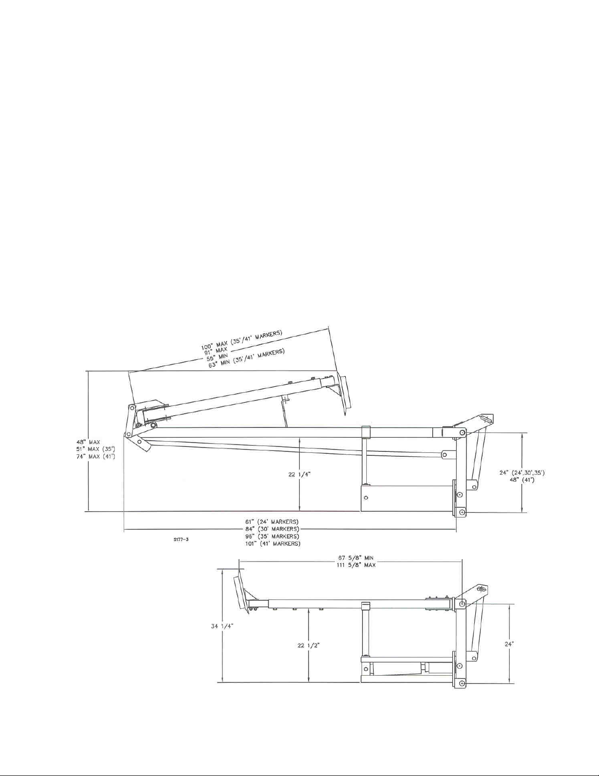
Yetter Drill Markers were designed to operate on grain drills and planters from 14 feet to 35 feet wide. For
non-folding grain drills from 14 to 22 feet wide, bi-fold markers are used.
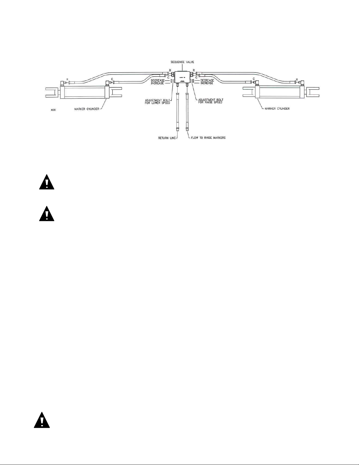
All Yetter Markers are hydraulically actuated. A sequence valve is provided to alternate automatically from
left to right marker. After each raise cycle the valve switches hydraulic oil flow to the opposite marker.
Yetter markers were designed for hydraulic systems providing up to 2500 psi hydraulic pressure. For
hydraulic systems that have variable flow control, this control may be used to adjust marker speed. It may
be necessary to provide restrictors in the lines to reduce marker speed with some tractors.
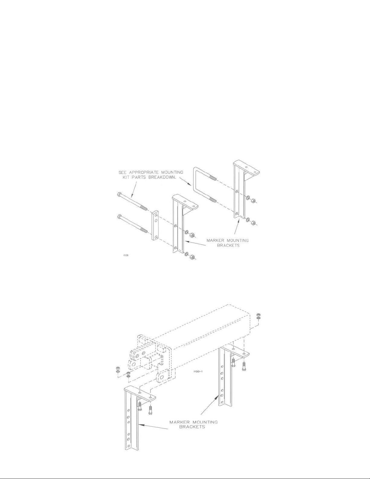
MOUNTING KIT INSTALLATION
On Great Plains, M & W, Marliss, Tye, IH5200/5400 and JD 750/1560, assemble mounting brackets to front
of drill frame as shown using hardware provided in the mounting kit for your particular type of drill. See
appropriate drawing and parts list.
MARKER INSTALLATION
Mount marker base to mounting brackets using 1/2 x 1-3/4” cap screws, lock washers and nuts. Two sets
of holes are provided in the marker base toward the outer end of the drill. Use the hole set that allows
clearance of obstruction on the frame for your particular implement.
NOTE: If drill is equipped with a grass seeder attachment, it may be necessary to install a marker
extension kit.
5
Page 6
INSTALLATION
HYDRAULIC SET-UP
FOR MARKERS
HYDRAULIC INSTALLATION
HYDRAULIC HOOK UP
DANGER:
Inspect and replace worn or frayed hydraulic hose. Keep all connections tight, escaping
hydraulic fluid under pressure can have sufficient force to penetrate the skin and cause serious injury.
Fluid escaping from a small hole can almost be invisible. Use a piece of cardboard or wood rather
than hands to search for suspected leaks. Failure to heed may result in personal injury or death.
WARNING:
hydraulic lines to install the marker hoses.
1.
Connect the port on the front of the sequence valve marked “LOWER” to the tractor or the return side of the drill lift
system. If the markers are to lower with a Yetter Coulter Cart, connect this LOWER port to the return side of the cart
hydraulic system. This is the bottom port of the right-hand (slave) cart cylinder.
2.
IMPORTANT – Be VERY careful when first actuating markers with hydraulic pressure. Cycle hydraulics several
times only slightly lifting marker off stops. Apply pressure for several seconds in raise position to purge air from
hydraulic cylinders. After several cycles, the marker should be completely lowered. When lowering the first time
proceed VERY slowly.
NOTE: Air left in the system will compress when pressurized, this may cause erratic and violent damaging
motion of the marker arms.
3.
Measure the time required for each marker to fold and unfold. If the markers are operating too fast, they must be
slowed down to provide adequate life. Bi-fold markers should take more than 4 seconds to fold and more than 4
seconds to unfold. Tri-fold markers should take more than 8 seconds to fold and more than 8 seconds to unfold.
4.
Some tractors have a provision to control remote cylinder speed with an adjustment near the remote cylinder ports.
If the markers are actuated with a separate tractor valve this adjustment is available.
5.
Restricted fittings are provided in all tri-fold markers to prevent damage from folding and unfolding too fast. If
markers are too slow drill out the restrictor fitting using a 1/16” drill bit.
6.
Adjustable restrictors are also provided in the sequence valve. These are adjusted with the bolts and jam nuts on
each side of the sequence valve. Adjustments of the raise speed are made with the bolt on the left side of the valve
with “RAISE” stamped vertically above it. Adjustments of the lowering speed are made with the bolt on the right side of
the valve with “LOWER” stamped vertically beneath it.
7.
Adjustments are made with these bolts by screwing them clockwise into the valve to reduce operating speed or by
screwing them counterclockwise to increase operating speed. Adjustments should be made in small increments, 1/6 of
turn or less at a time, being sure to retighten the jam nut.
WARNING:
hydraulic valve should be installed to operate the markers. If the markers are plumbed with an existing
switch operated valve they may extend or retract unexpectedly when you press the switch, resulting in
damage to equipment or property or possible injury to yourself or others in the vicinity.
Lower the cart to the ground, and remove any pressure in the lines before opening the
On drills and planters with switch operated hydraulic valves, a new switch operated
6
Page 7

SERVICE
MARKER SEQUENCE VALVE
SERVICE REPAIR KIT – 2515-349
DISASSEMBLY and ASSEMBLY
If markers do not sequence, clean dirt from valve
spool bore (6). If markers tend to creep
downward, check for dirt, nicks/scratches in ball
check valve areas (16).
Note: Be sure the hoses are connected to the
correct ports before disassembling the valve for
cleaning or repair. (See schematics.)
Disassembly:
1. Remove hex head plugs (1), springs (2), and
steel balls (16 & 17).
2. Remove plug (3), spring (2), steel ball (17).
3. Remove plugs (7) from each end of body.
Important! Be sure plugs, springs and balls (Step
1 and 2) are removed before attempting to
remove spool.
4. Carefully remove spool (6) from valve body.
5. Remove flow restrictor assembly (15) from
valve body.
Marker Operation
Markers fail to sequence
Raised marker slowly lowers
Valve spool stuck in sequence
valve
Check ball not seated in
Inspection:
1. Clean spool and restrictors in solvent.
Note: Restrictor disassembly is not required
for cleaning.
2. Clean valve body after checking exterior for
signs of o-ring leakage.
3. If spool is nicked or scratched, remove with
crocus cloth. Spool must slide freely in bore.
1. If ball seats are nicked or scratched, install
larger ball against seat, tap ball with brass
rod to “seat” ball.
Note: Remove spool for this procedure.
2. Inspect o-rings. Replace if necessary.
Assembly:
1. Apply clean hydraulic fluid to threads, orings, spool, valve bore. Reassemble in
reverse order of disassembly.
2. Open restrictors one turn minimum.
3. Install valve on planter and readjust marker
operating speed with restrictors.
Disassemble valve and clean
spool
Disassemble valve and reseat ball
7
Page 8
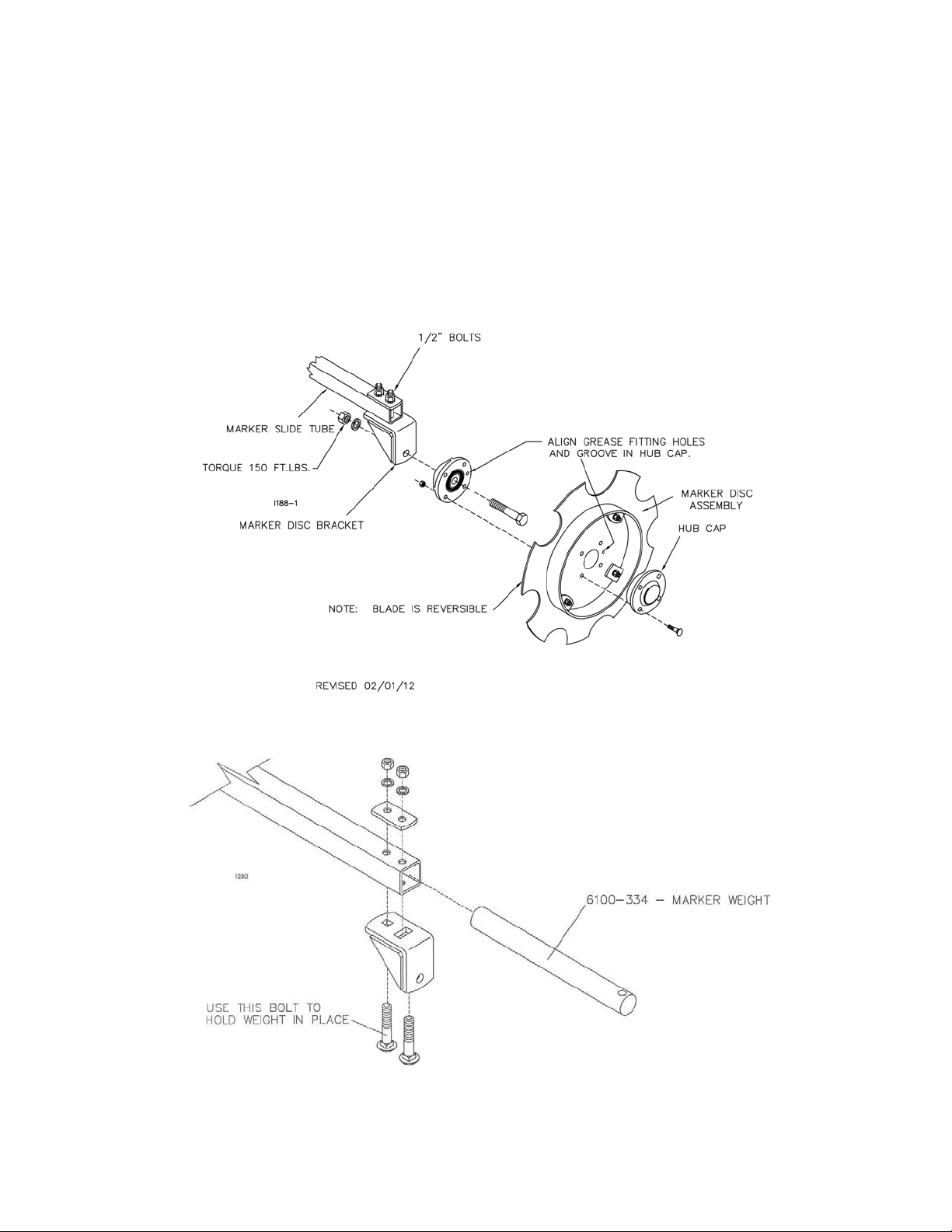
MARKER DISC ASSEMBLY
1. Assemble the marker disc assembly to the hub and bearing assembly, using a 5/16 x 1-1/4” carriage
bolts and locknuts then tighten.
2. Assemble hub and bearing assembly to the marker disc bracket using D-Bolt, 5/8” nut and lock washer
then tighten. Torque 150 ft./lbs.
3. Loosen the two 1/2” bolts on the outer end of the marker slide tube and adjust the marker disc brackets
to desired angle and retighten.
4. Fill hub and bearing assembly with general-purpose grease.
OPTIONAL
6100-334 – MARKER WEIGHT
8
Page 9
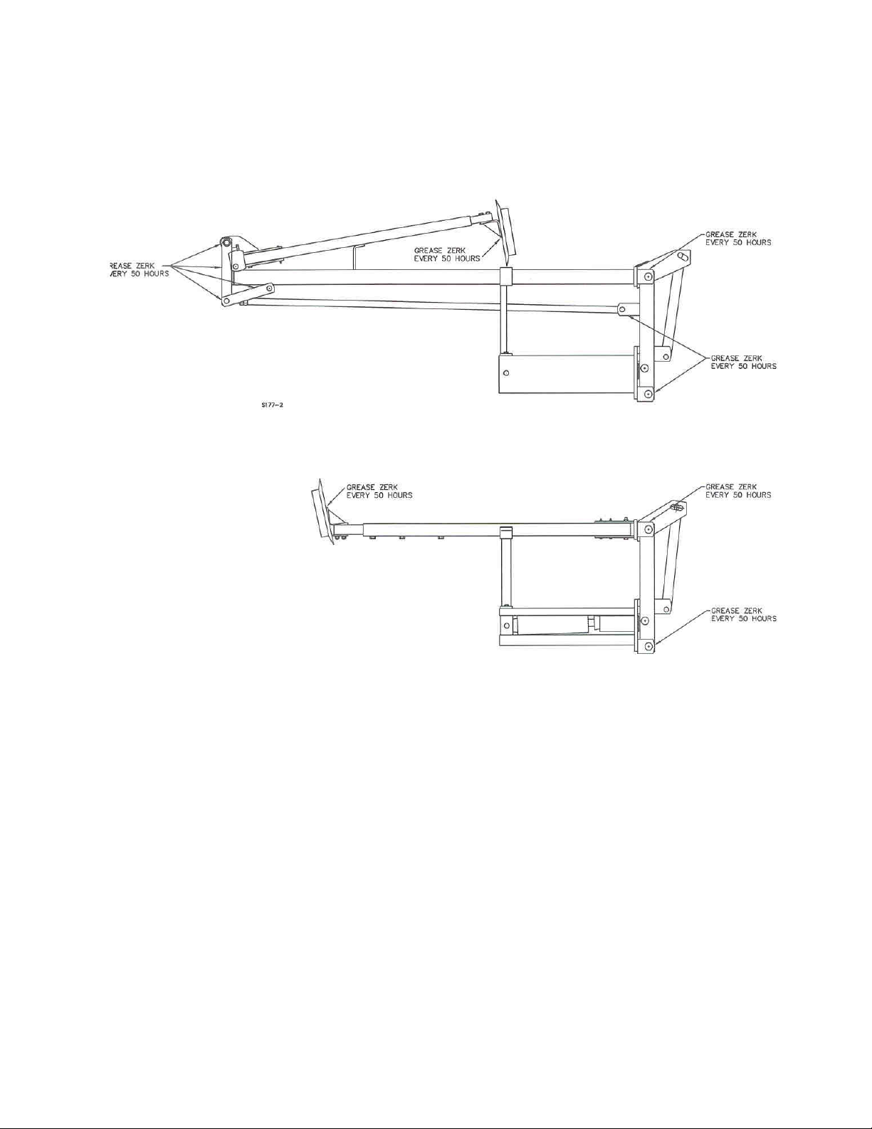
MAINTENANCE
MARKER
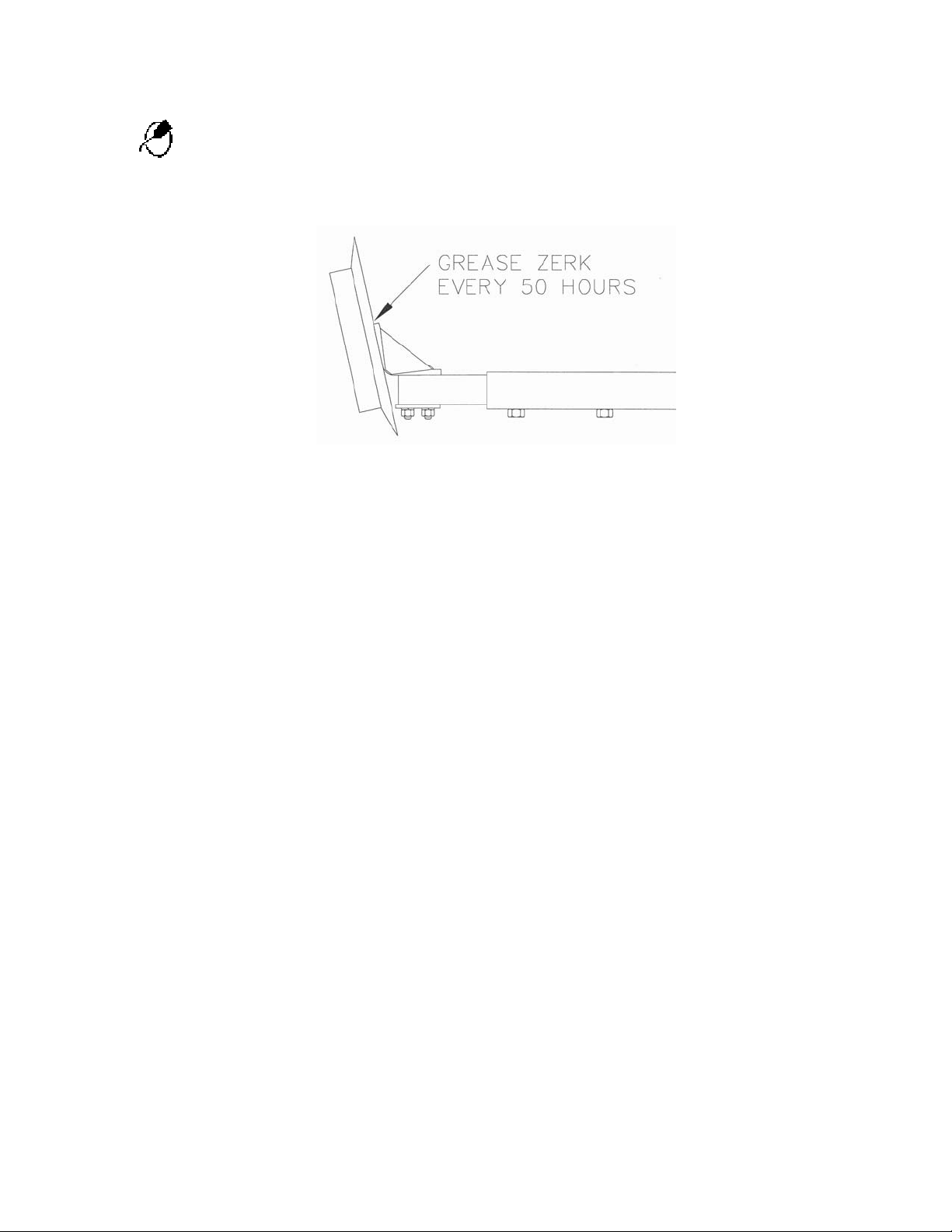
There are three grease zerks on the bi-fold marker and eight grease zerks on the tri-fold marker. (See
drawing). Grease every 50 hours. Grease the hub on each marker disc assembly every 50 hours.
9
Page 10
MAINTENANCE
BEARING ASSEMBLY AND LUBRICATION
Practice Safety
Understand and practice safe service procedures before doing work. Follow ALL the
operating, maintenance and safety information in the equipment operator manual. Clear
the area of bystanders, especially small children, when performing any maintenance or
adjustments. Keep work area clean and dry. Use adequate lighting for the job. Use only
tools, jacks and hoists of sufficient capacity for the job.
Never lubricate, service, or adjust machine while it is moving. Keep hands, feet, and
clothing from power-driven moving and rotating parts. Disengage all power and operate
controls to relieve pressure. Lower equipment to the ground and stop the engine.
Remove the key. Wait for all moving parts to stop before servicing, adjusting, repairing or
unplugging.
Securely support any machine elements with blocks or safety stands that must be raised
for service work.
Keep all parts in good condition and properly installed. Fix damaged equipment
immediately. Replace worn or broken parts. Remove any buildup of grease, oil, or debris.
Make sure all guards are in place and properly secured when maintenance work is
completed.
Assembly
10
Page 11
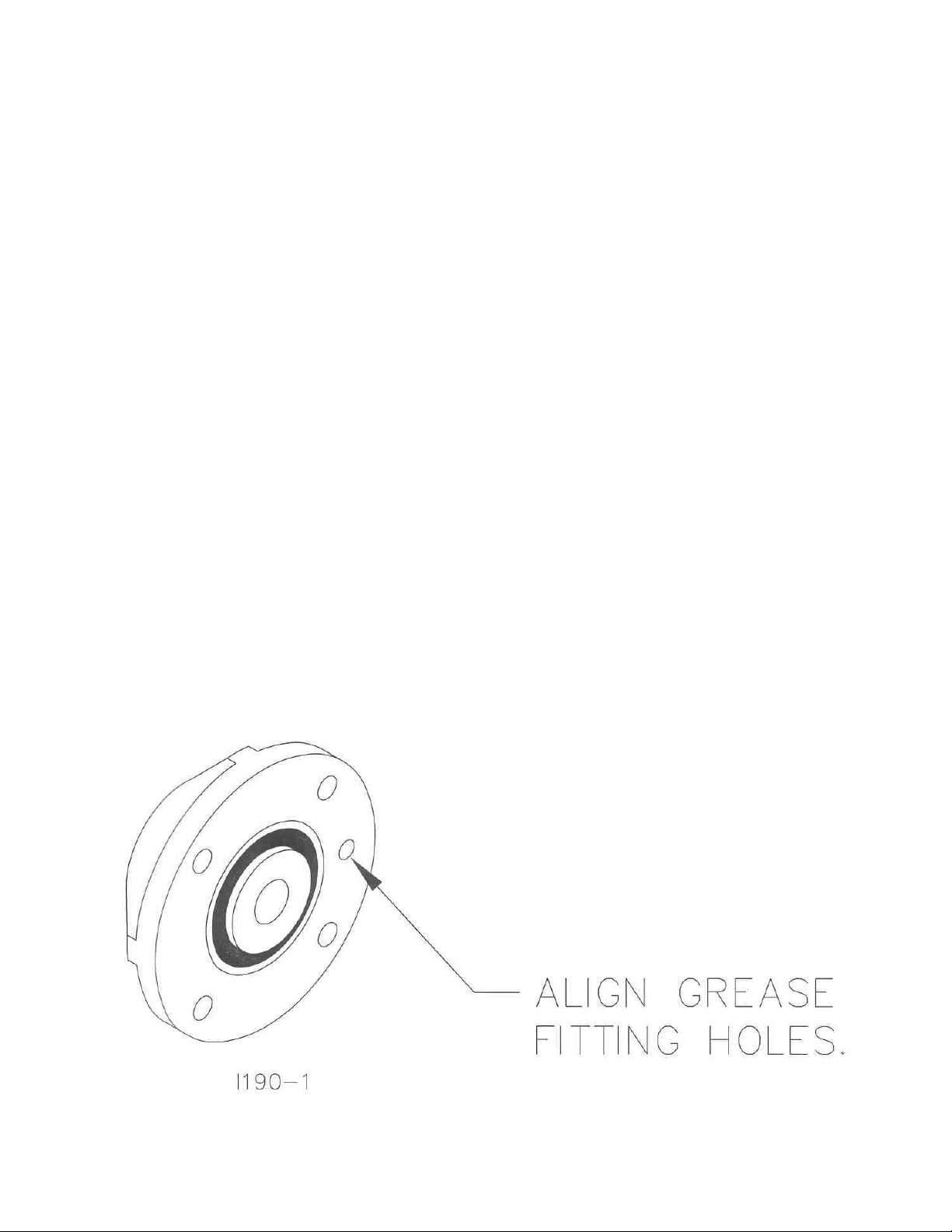
MAINTENANCE
NOTE: Be certain to align the grease fitting with the slot in the wheel and the hubcap so
that the grease can flow freely.
11
Page 12

MAINTENANCE
Hubcap cavity.
Grease must fill this
12
Page 13
MAINTENANCE
DESCRIPTION
OUNCES OF GREASE
Lubrication
CAUTION: To help prevent serious injury or death to you or others caused by
unexpected movement, service machine on a level surface. Lower machine to
ground or sufficiently lock or block raised machine before servicing. If machine
is connected to tractor, engage parking brake and place transmission in
"PARK", shut off engine and remove key. If machine is detached from tractor,
block wheels and use shop stands to prevent movement.
CAUTION: Do not clean, lubricate, or adjust machine while in motion.
Use grease based on NLGI consistency numbers and the expected air temperature range
during the service interval.
Use a multi-purpose lithium, water resistant, moderate speed, and NLGI grade #2
grease.
Other greases may be used if they meet the following NLGI Performance
Classification: GC-LB
IMPORTANT: Some types of grease thickener are not compatible with others. Consult
your grease supplier before mixing different types of grease.
Alternative Lubricants
Conditions in certain geographical areas may require special lubricants and lubrication
practices which do not appear in the operator's manual. If there are any questions,
consult Yetter Manufacturing Co. to obtain latest information and recommendation.
PART #
2967-404 13” TAPER TOOTH R.M. WHEEL 1.12 OZ
2967-602 13” SHARK TOOTH R.M. WHEEL 1.12 OZ
2967-186 FLOATER WHEEL KIT W/R.M. WHEEL 2.08 OZ
2967-596 HEAVY DUTY OR BEVEL R.M. WHEEL W/
FLOATER WHEEL KIT
2.40 OZ
Storing Lubricants
Your machine can operate at top efficiency only if clean lubricants are used.
Use clean containers to handle all lubricants.
Store them in an area protected from dust, moisture and other contaminants.
13
Page 14
MAINTENANCE
Lubrication Symbols
Lubricate with grease at hourly interval indicated on symbol.
Lubrication Intervals
IMPORTANT: The recommended service intervals are based on normal
conditions; severe or unusual conditions may require more frequent lubrication.
Perform each lubrication and service procedure at the beginning and end of
each season.
Clean grease fittings before using grease gun, to avoid injecting dirt and grit
into the bearing. Replace any lost or broken fittings immediately. If a fitting fails
to take grease, remove and clean thoroughly, replace fitting if necessary. Also
check for failure of adjoining parts.
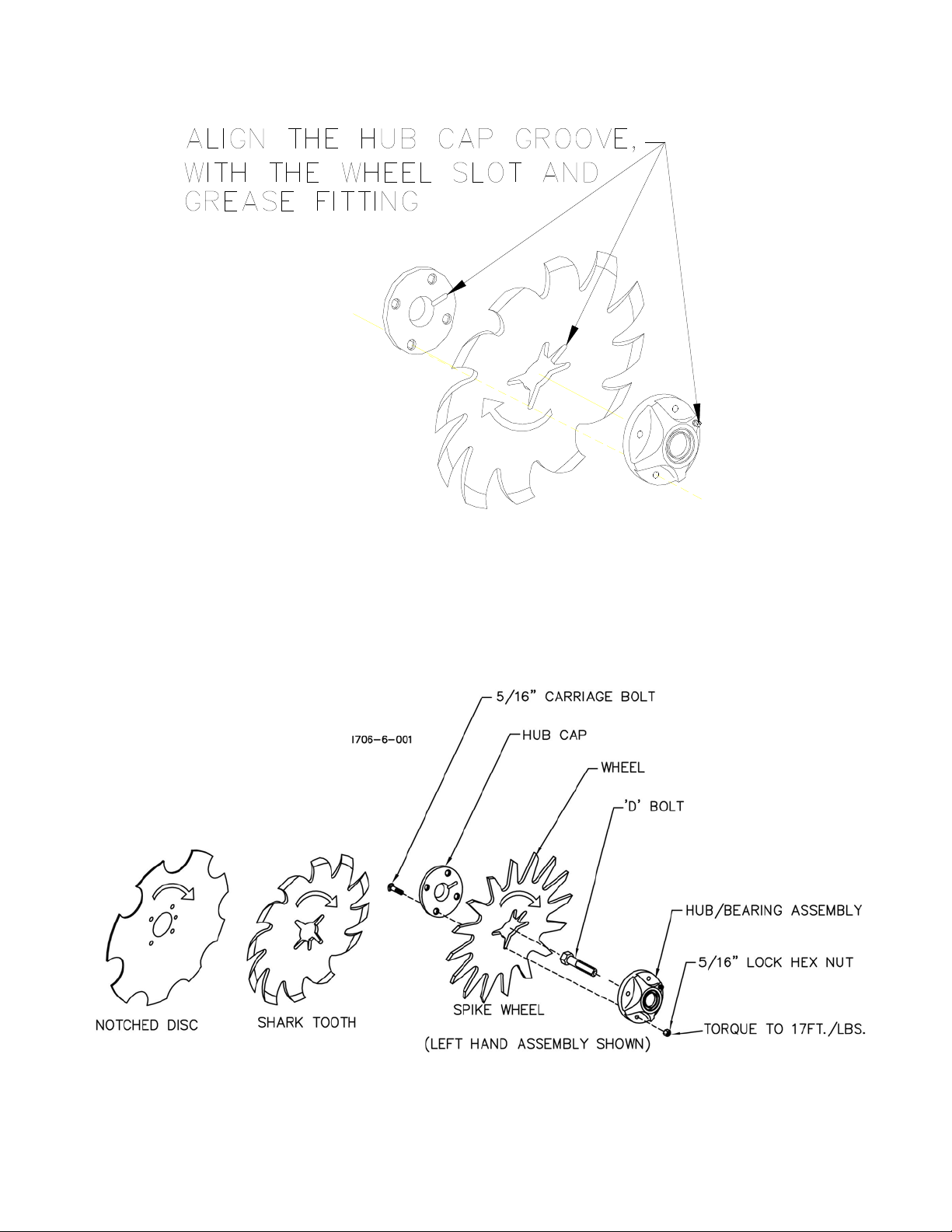
BEARING REPLACEMENT INSTALLATION
1. When assembling the spoke wheels, bearing assembly and hubcap, be sure to
align the grease transfer hole in the spoke wheel with the groove in the hubcap
and hole in the hub to allow grease passage.
2. Install/assemble the wheels, hubs and caps.
3. Grease the wheel/hub/bearing assembly.
14
Page 15

MAINTENANCE
Storing the Equipment
Store the machine in an area away from human activity
Store machine in RAISED position.
Install service locks on all wheel cylinders.
At the end of the season, the machine should be thoroughly inspected and prepared for storage.
Repair or replace any worn or damaged components to prevent down time at the start of the next
season. Store machine under cover with all parts in operating condition.
• Clean machine thoroughly to remove all dirt, debris and crop residue, which would hold
moisture and cause rusting.
• Inspect machine for worn or broken parts. See your Yetter Farm Equipment dealer during
the off-season so that parts or service can be acquired when machine is not needed in the
field.
• Lubricate bearings as outlined in the Lubrication section
• Paint all parts which are chipped or worn and require repainting.
• Store machine in a clean, dry place with the planting unit out of the sun.
• If the machine cannot be stored inside, cover with a waterproof tarpaulin and tie securely
in place.
•
Do not allow children to play on or around the machine
15
Page 16
PARTS IDENTIFICATION
16
Page 17

PARTS IDENTIFICATION
3” & 3-1/2” CYLINDER ASSEMBLY
4” CYLINDER ASSEMBLY
17
Page 18

PARTS IDENTIFICATION
6150-118 - HEAVY DUTY DISC KIT W/DEPTH BAND
KEY QTY. PART NO. DESCRIPTION
1 1 6150-133 HUB & BRACKET ASSEMBLY
(INCLUDES NO. 2,3,5,7,8,9, and 10)
2 1 6150-221 HD MARKER BRACKET W.A.
3 1 6600-160 HUB SUB ASSEMBLY
(INCLUDES NO. 4,5, and 6)
4 1 2550-054 SEAL, CR #12437
5 2 2550-053 1 1/16 BEARING L44649
6 1 6600-161 HUB WITH CUPS
(INCLUDES 2 CUPS (WILTON #L46610)
7 1 2570-197 WASHER, 1 ½ O.D. X 13/16 I.D.
8 1 2520-503 3/4-16 SLOTTED HEX NUT BLACK
9 1 2531-106 3/16 X 1-3/4 COTTER PIN BLACK
10 1 2570-196 HUB CAP
11 1 6001-609 .138 X 16" NOTCH MARKER DISC
12 4 2525-352 ½ MED LOCK WASHER ZYD
13 4 2502-344 ½-20 X 1 HHCS GR 5 ZYD
14 1 6150-253 HD DEPTH CONTROL BAND W.A.
15 4 2505-205 5/16-18 X 3/4¾CAR BLT GR 5 ZYD
16 4 2520-205 5/16-18 LOCK HEX NUT ZYD
MANUFACTURED 1/95 – 12/00
18
Page 19

PARTS IDENTIFICATION
19
Page 20

PARTS IDENTIFICATION
NOTCHED - MARKER DISC ASSEMBLY
20
Page 21

PARTS IDENTIFICATION
6001-016 – MARKER MOUNTING KIT, JOHN DEERE 1520
KEY QTY. PART NO. DESCRIPTION
1 4 6001-279 MARKER BRACKET W.A., JD 1520
2 3 2570-477 ¾ X 7 X 7 U-BOLT ZYD
3 8 2525-501 ¾ MED LOCK WASHER ZYD.
4 8 2520-504 ¾-10 HEX NUT ZYD.
5 1 6001-282 DOWN PRESSURE VALVE MTG. PLATE W.A.
6 2 2502-509 ¾-10 X 7 HHCS GR 5 ZYD
7 1 6001-451 SEQUENCE VALVE ADAPTER PLATE
8 2 2502-207 5/16-18 X 2 HHCS GR 5 ZYD
9 2 2520-205 5/16-18 LOCK HEX NUT ZYD
10 8 2520-352 ½-13 HEX NUT ZYD
11 8 2525-352 ½ MED LOCK WASHER ZYD
12 8 2502-317 ½-13 X 1 ¾ HHCS GR 5 ZYD
21
Page 22

PARTS IDENTIFICATION
6001-018 – MOUNTING KIT, JD 455 DRILLS
KEY QTY. PART NO. DESCRIPTION
1 4 6001-274 MOUNT ANGLE, JD 455, W.A.
2 4 2570-064 ¾ X 6 X 8 U-BOLT ZYD
3 8 2525-501 ¾ MED LOCK WASHER ZYD
4 8 2520-504 ¾-10 HEX NUT ZYD
5 8 2502-317 ½-13 X 1 ¾ HHCS GR 5 ZYD
6 8 2525-352 ½ MED LOCK WASHER ZYD
7 8 2520-352 ½-13 HEX NUT ZYD
22
Page 23

PARTS IDENTIFICATION
6001-022 – MOUNTING KIT, 15’ & 20’ TYE SERIES 5
30’ JOHN DEERE PLANTER 12 ROW 30”
KEY QTY. PART NO. DESCRIPTION
1 4 6001-259 21” MOUNT ANGLE W.A.
2 8 2502-317 ½-13 X 1 ¾ HHCS GR 5 ZYD
3 8 2525-352 ½ MED LOCK WASHER ZYD
4 8 2520-352 ½-13 HEX NUT ZYD
5 8 2520-504 ¾-10 HEX NUT ZYD
6 8 2525-501 ¾ MED LOCK WASHER ZYD
7 4 6001-477 1” SPACER, 7” BAR
8 4 2970-324 MOUNT STRAP
9 8 2502-520 ¾-10 X 11” HHCS GR 5 ZYD
23
Page 24

PARTS IDENTIFICATION
6001-026 – MARKER MOUNTING KIT, 7 X 7 CULTIVATOR
KEY QTY. PART NO. DESCRIPTION
1 4 2570-626 5/8 X 7 X 9 U-BOLT ZYD
2 8 2525-352 ½ MED LOCKWASHER ZYD
3 8 2520-459 5/8-11 HEX LOCK NUT ZYD
4 8 2502-294 ½-13 X 1-1/2 HHCS GR 5 ZYD
5 4 6001-353 MOUNT ANGLE, 7X7 CULTIVATOR
6 8 2520-352 ½-13 HEX NUT ZYD
24
Page 25

PARTS IDENTIFICATION
6001-028 – MARKER MOUNTING KIT
JOHN DEERE 750, 1560, 1590 15FT & 20FT
KEY QTY. PART NO. DESCRIPTION
1 4 2570-733 ¾ X 4 X 8 U-BOLT ZYD
2 8 2525-501 ¾ MED LOCK WASHER ZYD.
3 8 2520-504 ¾-10 HEX NUT ZYD
4 8 2502-351 ½-13 X 2 HHCS GR 5 ZYD
5 4 6001-416 MOUNTING PLATE, JD 750
6 8 2525-352 ½ MED LOCK WASHER ZYD
7 8 2520-352 ½-13 HEX NUT ZYD
25
Page 26

PARTS IDENTIFICATION
26
Page 27

PARTS IDENTIFICATION
27
Page 28

PARTS IDENTIFICATION
6001-042 – MOUNTING KIT, CASE IH 5500 DRILL
KEY QTY. PART NO. DESCRIPTION
1 16 2502-331 5/8-11 X 1 ¾ HHCS GR 5 ZYD
2 16 2520-459 5/8-11 LOCK HEX NUT ZYD
3 2 6001-275 MOUNTING BRACKET W.A., IH 5500
4 8 2502-351 ½-13 X 2 HHCS GR 5 ZYD
5 8 2520-357 ½-13 LOCK HEX NUT ZYD
6 2 6001-276 MOUNT ANGLE W.A., CASE IH 5500
7 2 2570-478 ¾ X 7 X 9 U-BOLT ZYD
8 2 6001-277 MOUNTING BRACE W.A., IH 5500
9 4 2520-515 ¾-10 LOCK HEX NUT ZYD
NOTE: SHOWN ON RIGHT HAND END OF DRILL.
28
Page 29

PARTS IDENTIFICATION
6001-120 – MOUNTING KIT, GREAT PLAINS
KEY QTY. PART NO. DESCRIPTION
1 4 6001-259 21” MOUNT ANGLE W.A.
2 8 2570-564 5/8 X 3-1/2 X 5 U-BOLT
3 16 2525-451 5/8 MED LOCK WASHER ZYD
4 16 2520-452 5/8-11 HEX NUT ZYD
5 8 2502-317 ½-13 X 1 ¾ HHCS GR 5 ZYD
6 8 2525-352 ½ MED LOCK WASHER ZYD
7 8 2520-352 ½-13 HEX NUT ZYD
8 8 6001-445 MOUNTING SPACER
NOTE: Part No. 6001-445, Mounting Spacer
Only used on drills with 7” or 10” spacing.
Also need to saw off bottom end of 6001-259
to obtain full range of seeding rates.
6001-118 – MOUNTING KIT, (M&W, MARLISS &TYE)
KEY QTY. PART NO. DESCRIPTION
1 4 6001-232 MOUNTING BRACKET W.A.
2 4 2570-564 5/8 X 3 ½ X 5 U-BOLT ZYD
3 8 2525-451 5/8 MED LOCK WASHER ZYD
4 8 2520-452 5/8-11 HEX NUT ZYD
5 8 2502-317 ½-13 X 1 ¾ HHCS GR 5 ZYD
6 8 2525-352 ½ MED LOCK WASHER ZYD
7 8 2520-352 ½-13 HEX NUT ZYD
29
Page 30

PARTS IDENTIFICATION
6001-191 – MARKER MOUNTING KIT, JD 515/520
(MOUNTED ON JD 515)
KEY QTY. PART NO. DESCRIPTION
1 4 6001-261 MOUNT ANGLE W.A., JD 515 & 520
2 6 2570-565 ½ X 2 X 3 U-BOLT ZYD
3 20 2525-352 ½ MED LOCK WASHER ZYD
4 20 2520-352 ½-13 HEX NUT ZYD
5 4 2570-602 5/8-11 X 3 X 4 ½ U-BOLT ZYD
6 12 2525-451 5/8 MED LOCK WASHER ZYD
7 12 2520-452 5/8-11 HEX NUT ZYD
8 4 2502-318 5/8-11 X 1 ½ HHCS GR 5 ZYD
9 2 6001-262 2 X 2 BAR W.A., JD 515 & 520
10 4 2502-503 ¾-10 X 2 HHCS GR 5 ZYD
11 1 6001-455 2 X 2 BAR BRACE, JD 515 & 520 (SHOWN)
1 6001-460 L.H. 2 X 2 BRACE, JD 515 & 520
12 4 2525-501 ¾ MED LOCK WASHER ZYD
13 4 2520-504 ¾-10 HEX NUT ZYD
14 8 2502-317 ½-13 X 1 ¾ HHCS GR 5 ZYD
30
Page 31

PARTS IDENTIFICATION
6001-191 – MARKER MOUNTING KIT, JD 515/520
(MOUNTED ON JD 520)
KEY QTY. PART NO. DESCRIPTION
1 4 6001-261 MOUNT ANGLE W.A., JD 515 & 520
2 6 2570-565 ½ X 2 X 3 U-BOLT ZYD
3 20 2525-352 ½ MED LOCK WASHER ZYD
4 20 2520-352 ½-13 HEX NUT ZYD
5 4 2570-602 5/8-11 X 3 X 4 ½ U-BOLT ZYD
6 12 2525-451 5/8 MED LOCK WASHER ZYD
7 12 2520-452 5/8-11 HEX NUT ZYD
8 4 2502-318 5/8-11 X 1 ½ HHCS GR 5 ZYD
9 2 6001-262 2 X 2 BAR W.A., JD 515 & 520
10 4 2502-503 ¾-10 X 2 HHCS GR 5 ZYD
11 1 6001-455 2 X 2 BAR BRACE, JD 515 & 520 (SHOWN)
1 6001-460 L.H. 2 X 2 BRACE, JD 515 & 520
12 4 2525-501 ¾ MED LOCK WASHER ZYD
13 4 2520-504 ¾-10 HEX NUT ZYD
14 8 2502-317 ½-13 X 1 ¾ HHCS GR 5 ZYD
31
Page 32

PARTS IDENTIFICATION
6001-195 – MARKER MOUNTING KIT, CASE IH 5200/5400
KEY QTY. PART NO. DESCRIPTION
1 2 6001-266 R.H. MARKER MOUNT W.A., IH 5200 (SHOWN)
2 6001-267 L.H. MARKER MOUNT W.A., IH 5200
2 4 2570-478 ¾ X 7 X 9 U-BOLT ZYD
3 8 2525-501 ¾ MED LOCK WASHER ZYD
4 8 2520-504 ¾-10 HEX NUT ZYD
5 8 2502-317 ½-13 X 1 ¾ HHCS GR 5 ZYD
6 8 2525-352 ½ MED LOCK WASHER ZYD
7 8 2520-352 ½-13 HEX NUT ZYD
32
Page 33

PARTS IDENTIFICATION
NOTE: May also be used
on 4 x 4 toolbar.
6001-198 – MARKER MOUNTING KIT, JD 750, 1560, 1590 - 30 FT. MARKERS
KEY QTY. PART NO. DESCRIPTION
1 8 2502-335 5/8-11 X 6 HHCS GR 5 ZYD
2 4 6001-268 MOUNTING ANGLE W.A., JD 750
3 4 6001-470 CLAMP PLATE, JD 750
4 8 2525-451 5/8 MED LOCK WASHER ZYD
5 8 2520-452 5/8-11 HEX NUT ZYD
6 8 2502-317 ½-13 X 1 ¾ HHCS GR 5 ZYD
7 8 2525-352 ½ MED LOCK WASHER ZYD
8 8 2520-352 ½-13 HEX NUT ZYD
33
Page 34

PARTS IDENTIFICATION
34
Page 35

PARTS IDENTIFICATION
NOTE:
MAY BE USED WHEN TRYING TO CLEAR FERTLIZER TANKS.
ON PLANTERS, 6001-022 MOUNTING KIT
6100-110 – PLANTER MARKER KIT
5 X 7, 7 X 7 TOOLBAR
KEY QTY. PART NO. DESCRIPTION
1 4 2570-478 ¾ X 7 X 9 U-BOLT ZYD
2 4 6100-213 MOUNTING BRACKET W.A. PLANTER
3 8 2526-501 ¾ STANDARD FLAT WASHER ZYD
4 8 2525-501 ¾ MED LOCK WASHER ZYD
5 8 2520-504 ¾-10 HEX NUT ZYD
6 8 2502-317 ½-13 X 1 ¾ HHCS GR 5 ZYD
7 8 2525-352 ½ MED LOCK WASHER ZYD
8 8 2520-352 ½-13 HEX NUT ZYD
35
Page 36

PARTS IDENTIFICATION
36
Page 37

PARTS IDENTIFICATION
37
Page 38

PARTS IDENTIFICATION
38
Page 39

PARTS IDENTIFICATION
39
Page 40

PARTS IDENTIFICATION
40
Page 41

MARKER EXTENSION KITS
(FOR USE WITH GRASS SEEDER ATTACHEMENTS)
6001-179 – MARKER EXTENSION KIT, GREAT PLAINS
KEY QTY. PART NO. DESCRIPTION
1 4 6001-459 MARKER EXTENSION ANGLE, GREAT PLAINS
2 8 2502-351 ½-13 X 2 HHCS GR 5 ZYD
3 8 2525-352 ½ MED LOCK WASHER ZYD
4 8 2520-352 ½-13 HEX NUT ZYD
6001-199 – MARKER EXTENSION KIT, JD 515/520
KEY QTY. PART NO. DESCRIPTION
1 4 6001-476 MARKER EXTENSION, JD 515/520
2 4 2502-296 ½-13 X 2-1/2 HHCS GR 2 ZYD
3 4 2525-352 ½ MED LOCK WASHER ZYD
4 4 2520-352 ½-13 HEX NUT ZYD
41
Page 42

PARTS IDENTIFICATION
42
Page 43

PARTS IDENTIFICATION
43
Page 44

PARTS IDENTIFICATION
44
Page 45

PARTS IDENTIFICATION
6/98 TO 6/04
45
Page 46

PARTS IDENTIFICATION
6/98 TO 6/04
46
Page 47

PARTS IDENTIFICATION
47
Page 48

Problem
Markers do not function
correctly
Marker blade does not leave
good enough mark
Both markers activate at
same time
Marker blade digging too
much dirt
Tri-fold marker will not raise
from operating position
TROUBLESHOOTING
Cause
Markers raise and lower
voluntarily
Blade not moving sufficient
dirt
Sequence valve not operating
Blade set at incorrect angle
Not enough hydraulic
pressure
Solution
Check tractor hydraulic
system
Check hydraulic hose
couplings
Purge air from hydraulic
system see Installation:
hydraulic hoses
Hydraulic cylinder failure,
repair as necessary
Check sequence valve for dirt
or damage.
Adjust angle of blade to be
more aggressive.
Use notched marker blade,
6001-495. (6001-610 w/depth
band assembly.)
Reverse blades on hubs to
push dirt out.
Air in hydraulic lines
Check for dirt in spool or
replace sequence valve
Adjust angle of blade to be
less aggressive
Check and repair tractor
hydraulic pump (2400 PSI
minimum)
Replace hydraulic cylinder
with ½” larger diameter
cylinder. Example: replace a
3” x 8” cylinder with a 3-1/2” x
8” cylinder
48
Page 49

PARTS IDENTIFICATION
49
Page 50

NOTES:
50
Page 51

NOTES:
51
Page 52

Our name
Is getting known
J
ust a few years ago, Yetter products were sold
primarily to the Midwest only. Then we embarked on a
program of expansion and moved into the East, the
South, the West and now north into Canada. We’re even
getting orders from as far away as Australia and Africa.
S
o, when you buy Yetter products . . .you’re buying a
name that’s recognized. A name that’s known and
respected. A name that’s become a part of American
agriculture and has become synonymous with quality and
satisfaction in the field of conservation tillage.
T
hank you.
YETTER MANUFACTURING CO.
Colchester, IL 62326-0358 309/776-4111
Toll Free 800/447-5777
Fax 309/776-3222
Website: www.yetterco.com
E-mail: info@yetterco.com
2565-376_REV_E
03/14
52
 Loading...