

Page 1
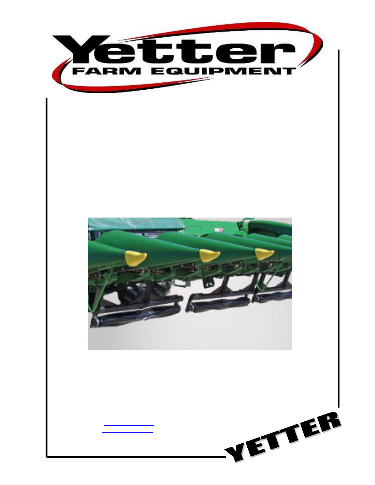
5000 SERIES
STALK
DEVASTATOR
CORN STALK ROLLER
*PATENTED*
5000-022
OPERATOR’S MANUAL
PART IDENTIFICATION
2565-783 – 07/2014
YETTER MANUFACTURING CO.
FOUNDED 1930
Colchester, IL 62326-0358
Toll free: 800/447-5777
309/776-3222 (Fax)
Website: www.yetterco.com
E-mail: info@yetterco.com
Page 2

FOREWORD
You’ve just joined an exclusive but rapidly
growing club.
For our part, we want to welcome you to the
group and thank you for buying a Yetter product.
We hope your new Yetter products will help you
achieve both goals-increase your productivity and
increase your efficiency so that you may generate
more profit.
This operator’s manual has been designed into
four major sections: Foreword, Safety
Precautions, Installation Instructions and Parts
Breakdown.
This SAFETY ALERT SYMBOL
indicates important safety messages in
the manual. When you see this
symbol, be alert to the possibility of
PERSONAL INJURY and carefully
read the message that follows.
The word NOTE is used to convey information
that is out of context with the manual text. It
contains special information such as
specifications, techniques and reference
information of a supplementary nature.
The word IMPORTANT is used in the text when
immediate damage will occur to the machine due
to improper technique or operation. Important will
apply to the same information as specified by
note only of an immediate and urgent nature.
It is the responsibility of the user to read the
operator’s manual and comply with the safe and
correct operating procedure and to lubricate and
maintain the product according to the
maintenance schedule in the operator’s manual.
The user is responsible for inspecting his
machine and for having parts repaired or
replaced when continued use of the product
would cause damage or excessive wear to the
other parts.
It is the user’s responsibility to deliver his
machine to the Yetter dealer who sold him the
product for service or replacement of defective
parts, which are covered by the warranty policy.
If you are unable to understand or follow the
instructions provided in this publication, consult
your local Yetter dealer or contact:
YETTER MANUFACTURING CO.
309/776-4111
800/447-5777
309/776-3222 (FAX)
Website: www.yetterco.com
E-mail: info@yetterco.com
WARRANTY
Yetter Manufacturing warrants all products manufactured and sold by it against defects in material. This
warranty being expressly limited to replacement at the factory of such parts or products as shall appear to
be defective after inspection. This warranty does not obligate the Company to bear cost of labor in
replacement of parts. It is the policy of the Company to make improvements without incurring obligations to
add them to any unit already sold. No warranty is made or authorized to be made, other than herein set
forth. This warranty is in effect for one year after purchase.
DEALER: ________________________________________
Yetter Manufacturing warrants its own products only and cannot be responsible for damages to
equipment on which mounted.
2
Page 3

BE ALERT!
YOUR SAFETY IS INVOLVED.
WATCH FOR THIS SYMBOL. IT POINTS OUT IMPORTANT SAFETY
PRECAUTIONS. IT MEANS “ATTENTION---BECOME ALERT!”
It is your responsibility as an owner, operator, or supervisor to know and instruct everyone using this
machine at the time of initial assignment and at least annually thereafter, of the proper operation,
precautions, and work hazards which exist in the operation of the machine in accordance with OSHA
regulations.
Safety Is No Accident
The following safety instructions, combined with common sense, will save your equipment from
needless damage and the operator from unnecessary exposure to personal hazard. Pay special
attention to the caution notes in the text. Review this manual at least once each year with new
and/or experienced operators.
1. Read and understand the operator’s manual before operating this machine. Failure to do
so is considered a misuse of the equipment.
2. Make sure equipment is secure before operating.
3. Always keep children away from equipment when operating.
4. Make sure everyone that is not directly involved with the operation is out of the work area
before beginning the operation.
5. Make sure all safety devices, shields, and guards are in place and are functional before
beginning the operation.
6. Shut off power to adjust, service, or clean.
7. Keep hands, feet, and clothing away from moving parts. It is a good idea to remove all
jewelry before starting the operation.
8.
Visually inspect the machine periodically during operation for signs of excessive vibration,
loose fasteners, and unusual noises.
3
Page 4

PLEASE READ, VERY IMPORTANT
SECURE CORN HEADER AGAINST
UNWANTED LOWERING BY APPLYING
THE LOCKING MECHANISM ON THE
HYDRAULIC CYLINDERS!
1. ATTACH HEAD TO COMBINE, LOCK HEAD TO COMBINE
2. RAISE THE HEAD OFF THE GROUND AND ENGAGE THE SAFETY
STOP ON THE FEEDER HOUSE CYLINDER.
3. TURN OFF COMBINE ENGINE AND REMOVE KEY.
FOLLOW THE INSTRUCTIONS OF THE COMBINE
MANUFACTURER.
4
Page 5

PLEASE READ, VERY IMPORTANT
Subject to the size and weight of the corn header, one or two additional
hydraulic cylinders may be required.
The combine manufacturer generally keeps the corresponding kits readily
available for the dealer.
Subject to the design of the corn header and carrying capacity of the
different combines, the steering axle may require the fitting of additional
weights and the rear tires might need to be filled with ballast.
FOLLOW THE INSTRUCTIONS OF THE COMBINE
MANUFACTURER.
5
Page 6

TABLE OF CONTENTS
INTRODUCTION…………………………………………………………….…..2
WARRANTY………………………………………………………………….….2
SAFETY INFORMATION…………………………………………………….2-5
TABLE OF CONTENTS…………………………………………………….….6
TORQUE………………………………………………………………………....7
PARTS IDENTIFICATON
5000-022………………………………………………………………….8-10
ASSEMBLY INSTRUCTIONS…………………………………………….11-16
LOCK UP PIN…………………………………………………………………..17
6
Page 7

BOLT TORQUE
Mounting bolts and hardware
All hardware used on the 5000 Devastator is Grade 5 unless otherwise noted. Grade 5
cap screws are marked with three radial lines on the head. If hardware must be replaced,
be sure to replace it with hardware of equal size, strength and thread type. Refer to the
torque values chart when tightening hardware.
Important: Over tightening hardware can cause as much damage as when
under tightening. Tightening hardware beyond the recommended range can
reduce its shock load capacity.
The chart below is a guide for proper torque. Use it unless a specified torque is called out
elsewhere in the manual.
Torque is the force you apply to the wrench handle or the cheater bar, times the length of the
handle or bar.
Use a torque wrench whenever possible.
The following table shows torque in ft. lbs. for coarse thread hardware.
7
Page 8

PARTS IDENTIFICATION
8
Page 9

PARTS IDENTIFICATION
9
Page 10
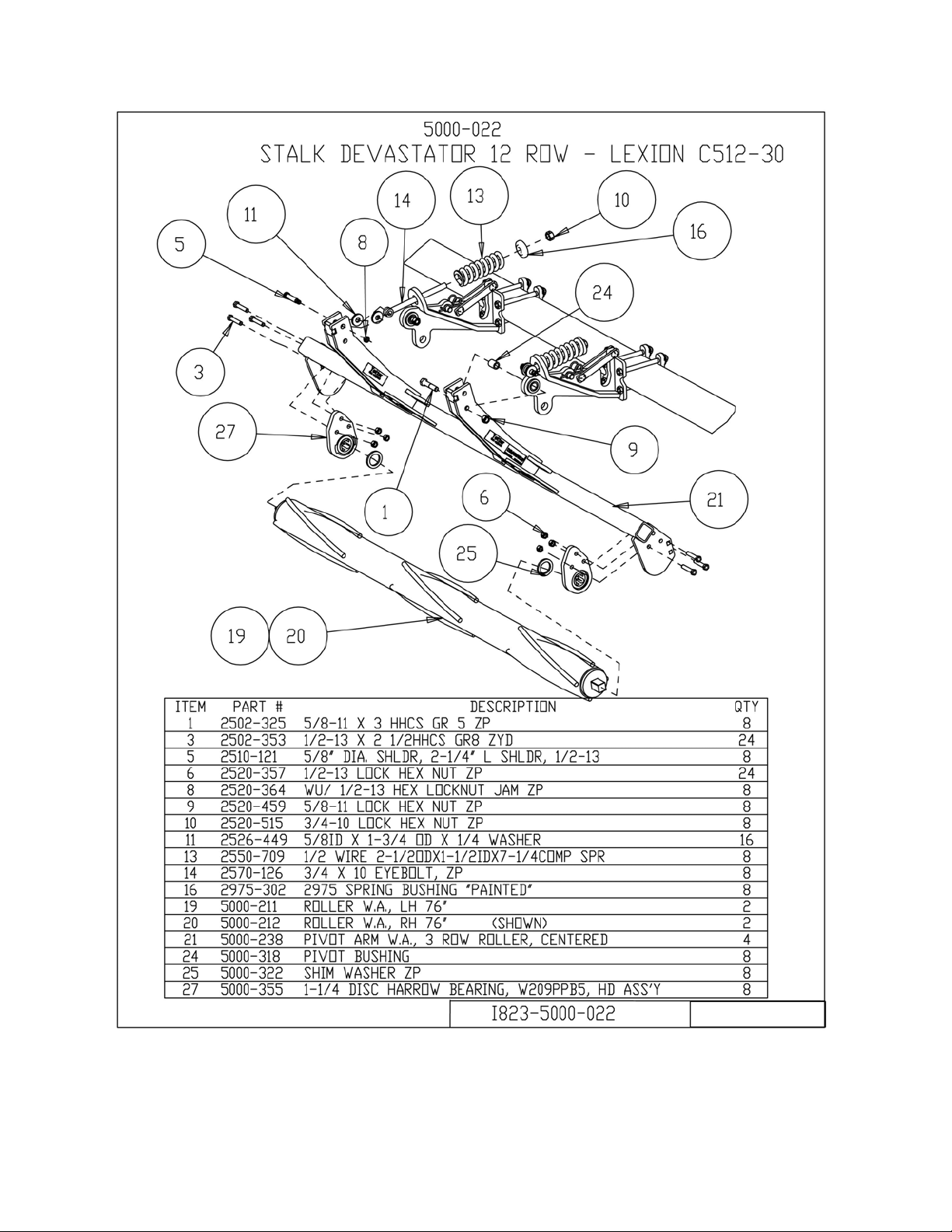
PARTS IDENTIFICATION
10
Page 11

ASSEMBLY INSTRUCTIONS
STEP 1. ATTACH THE 5000-250 MOUNT BRACKETS TO THE FRAME USING THE
5/8” X 8 BOLTS, STRAPS, FLAT WASHER AND LOCK HEX NUTS.
NOTE: DO NOT FULLY TIGHTEN HARDWARE UNTIL THE PIVOT ARMS ARE
INSTALLED AT STEP 4.
11
Page 12

ASSEMBLY INSTRUCTIONS
STEP 2. ATTACH THE 5000-309 SUPPORT STRAPS USING THE ½” X 2 CARRIAGE
BOLTS AND FLANGE LOCK NUTS.
12
Page 13

ASSEMBLY INSTRUCTIONS
STEP 3. INSTALL THE 5000-323 LOCK UP PIN IN THE STORAGE LOCATION ON
THE MOUNT BRACKETS SECURE WITH THE HAIRPIN CLIPS.
13
Page 14

ASSEMBLY INSTRUCTIONS
STEP 4. ATTACH THE 5000-238 PIVOT ARMS TO THE MOUNT BRACKETS USING
THE 5/8” X 3 BOLTS, PIVOT BUSHINGS AND LOCK HEX NUTS. FULLY TIGHTEN
ALL THE HARDWARE AT THIS TIME, MOUNTING BOLTS INCLUDED.
14
Page 15

ASSEMBLY INSTRUCTIONS
STEP 5. INSTALL THE PUSH RODS INTO THE MOUNT BRACKETS THEN ATTACH
TO THE PIVOT ARMS WITH THE 5/8” SHOULDER BOLTS, WASHERS AND ½” JAM
LOCK HEX NUTS.
NOTE: THE WASHERS ARE INSTALLED ON EACH SIDE OF THE “EYE” OF THE
PUSH ROD.
NOW INSTALL THE COMPRESSION SPRINGS, SPRING BUSHINGS AND ¾’ LOCK
HEX NUTS.
15
Page 16

ASSEMBLY INSTRUCTIONS
STEP 6. INSTALL THE SHIMS AND BEARINGS ONTO THE ROLLERS.
NOTE: THE EXTENDED RACE ON THE BEARING WILL FACE TOWARD THE
ROLLER.
ATTACH THE BEARING/ROLLER ASSEMBLY TO THE PIVOT ARMS USING THE ½” X
2-1/2” BOLTS AND 1/2'” LOCK HEX NUTS.
THE SIDE OF THE BEARING
ASSEMBLY WHERE THE
BEARING IS PROTRUDING
MUST BE INSTALLED
TOWARD THE ROLLER!
16
Page 17

17
Page 18

NOTES:
18
Page 19

NOTES:
19
Page 20

Our name
Is getting known
Just a few years ago, Yetter products were sold primarily to the
Midwest only. Then we embarked on a program of expansion and
moved into the East, the South, the West and now north into Canada.
We’re even getting orders from as far away as Australia and Africa.
So, when you buy Yetter products . . .you’re buying a name that’s
recognized. A name that’s known and respected. A name that’s
become a part of American agriculture and has become synonymous
with quality and satisfaction in the field of conservation tillage.
Thank you.
YETTER MANUFACTURING CO.
Colchester, IL 62326-0358 • 309/776-4111
Toll Free 800/447-5777
Fax 309/776-3222
Website: WWW.YETTERCO.COM
E-MAIL: INFO@YETTERCO.COM
2565-783 • 07/14
20
 Loading...