

Page 1

3400 & 3500 SERIES
TOOLBAR ROTARY HOE
PATENTED
2565-118_REV_E
OPERATOR’S MANUAL
PART IDENTIFICATION
•
02/12
YETTER MANUFACTURING CO.
FOUNDED 1930
Colchester, IL 62326-0358
Toll free: 800/447-5777
309/776-3222 (Fax)
Website: www.yetterco.com
E-mail: info@yetterco.com
Page 2

FOREWORD
You’ve just joined an exclusive but rapidly
growing club.
For our part, we want to welcome you to the
group and thank you for buying a Yetter product.
We hope your new Yetter implement will help you
achieve both increased productivity and
increased efficiency so that you may generate
more profit. This operator’s manual has been
designed into six major sections.
Foreword, Safety Precautions, assembly
instructions, Operation, parts identification and
troubleshooting.
It is important the owner/operator knows the
implement model number and serial number.
Write the serial and model number in the space
provided and use it in all correspondence when
referring to the implement.
Throughout the manual references may be made
to left side and right side. These terms are used
as viewed from the operator’s seat facing the
front of the tractor.
This SAFETY ALERT SYMBOL indicates
important safety messages in the manual.
When you see this symbol, be alert to the
possibility of PERSONAL INJURY and carefully
read the message that follows.
YETTER MANUFACTURING CO.
309/776-4111
800/447-5777
309/776-3222 (FAX)
Website: www.yetterco.com
E-mail: info@yetterco.com
WARRANTY POLICY
Yetter Manufacturing warrants all products manufactured and sold by it against defects in material. This warranty being
expressly limited to replacement at the factory of such parts or products as will appear to be defective after inspection.
This warranty does not obligate the Company to bear cost of labor in replacement of parts. It is the policy of the
company to make improvements without incurring obligations to add them to any unit already sold. No warranty is
made or authorized to be made, other than herein set forth. This warranty is in effect for one year after purchase.
Model Number:_________________________
Serial Number:_________________________
Dealer :___________________
The serial and model numbers are located on the top of the left hitch plate.
Yetter Manufacturing warrants its own products only and cannot be responsible for damage to
equipment on which mounted.
2
The word NOTE is used to convey information
that is out of context with the manual text. It
contains special information such as
specifications, techniques, reference information
and other information of a supplementary nature.
The word IMPORTANT is used in the text when
immediate damage will occur to the machine due
to improper technique or operation. Important will
apply to the same information as specified by
note only of an immediate and urgent nature.
It is the responsibility of the user to read the
operator’s manual and comply with the safe and
correct operating procedure and to lubricate and
maintain the product according to the
maintenance schedule in the operator’s manual.
The user is responsible for inspecting his
machine and for having parts repaired or
replaced when continued use of the product
would cause damage or excessive wear to the
other parts.
It is the user’s responsibility to deliver his
machine to the Yetter dealer who sold
him the product for service or
replacement of defective parts that are covered
by the warranty policy.
If you are unable to understand or follow the
instructions provided in the publication, consult
you local Yetter dealer or contact:
Page 3

SAFETY PRECAUTIONS
You can make your farm a safer place to live and work if you observe the safety precautions given. Study
these precautions carefully and insist that those working with you and for you follow them.
Finally, remember this: an accident is usually caused by someone’s carelessness, neglect or oversight.
DANGER
Inspect and replace worn or frayed hydraulic hose, keep all connections tight. Escaping hydraulic fluid
under pressure can have sufficient force to penetrate the skin and cause serious personal injury. Fluid
escaping from a small hole can be almost invisible. Use a piece of cardboard or wood rather than the
hands to search for suspected leaks.
CAUTION
Consult your implement and tractor operator’s manual for correct and safe operating practices. Be aware of
towed implement width and allow safe clearance.
CAUTION: SAFETY SIGNS
Safety decals are placed on the implement to alert the operator and others to the risk of personal injury or
unsafe operation during normal operations and servicing.
1. The safety decals must be kept clean and in good condition to ensure that they are legible.
2. Safety decals must be replaced if they are missing or illegible.
3. When components are replaced during repair or servicing, check that the new components include
the necessary safety signs.
4. Replacement safety decals may be obtained from your local Yetter dealer.
WARNING
Never clean, lubricate or adjust a machine that is in motion. Always install the transport lock pins and bracket when
transporting for any length of time or on public roadways.
If required to service unit in raised position, be sure to install all transport lock pins and locking bracket.
Be sure the implement is securely locked in the 3-point quick hitch before operating.
Do not allow children to operate this equipment.
Do not allow riders on the tractor or implement.
Use speeds and caution dictated by the terrain being traversed. Do not operate on any slope steep enough to cause
tipping or loss of control.
Be sure all personnel are clear of the immediate area before operating.
Read and understand the operator’s manual and require all other persons who will operate the equipment to do the
same.
In operating on public roadways, where legal, be certain all lighting is operating properly and observe all traffic laws.
Ensure slow moving vehicle emblem on tractor is visible.
Beware of increased stopping distances and control effort when operating with implements attached.
Be familiar with all tractor and implement controls and be prepared to stop engine and implements quickly in an
emergency.
FAILURE TO HEED MAY RESULT IN PERSONAL INJURY OR DEATH
3
Page 4

3400 MODEL SPECIFICATIONS
MODEL NO. OF TOOLBAR APPROX.
NO. SECTIONS LENGTH WEIGHT
3412-101 3 149” (12’5”) 1250#
3415-101 4 184” (15’4”) 1600#
3421-101 6 254” (21’2”) 2400#
3428-101 8 338” (28’2”) 3050#
3430-101 8 366” (30’6”) 3300#
3434-101 8 408” (34’) 3700#
3400 ROW COVERAGES
3412-101 12’ 3 SECTION HOE
42” ROWS – 3 ROWS WITH 21” OVERLAP
40” ROWS – 3 ROWS WITH 29” OVERLAP
38” ROWS – 3 ROWS WITH 33” OVERLAP
36” ROWS – 4 ROWS WITH 3” OVERLAP
34” ROWS – 4 ROWS WITH 11” OVERLAP
32” ROWS – 4 ROWS WITH 19” OVERLAP
30” ROWS – 4 ROWS WITH 27” OVERLAP
28” ROWS – 5 ROWS WITH 7” OVERLAP
26” ROWS – 5 ROWS WITH 17” OVERLAP
24” ROWS – 6 ROWS WITH 3” OVERLAP
22” ROWS – 6 ROWS WITH 15” OVERLAP
20” ROWS – 7 ROWS WITH 7” OVERLAP
3421-101 21’ 6 SECTION HOE
42” ROWS – 6 ROWS WITH NO OVERLAP
40” ROWS – 6 ROWS WITH 12” OVERLAP
38” ROWS – 6 ROWS WITH 24” OVERLAP
36” ROWS – 7 ROWS WITH NO OVERLAP
34” ROWS – 7 ROWS WITH 14” OVERLAP
32” ROWS – 7 ROWS WITH 28” OVERLAP
30” ROWS – 8 ROWS WITH 12” OVERLAP
28” ROWS – 9 ROWS WITH NO OVERLAP
26” ROWS – 9 ROWS WITH 18” OVERLAP
24” ROWS – 10 ROWS WITH 12” OVERLAP
22” ROWS – 11 ROWS WITH 10” OVERLAP
20” ROWS – 12 ROWS WITH 12” OVERLAP
3430-101 30’ 8 SECTION HOE
42” ROWS – 8 ROWS WITH 28” OVERLAP
40” ROWS – 9 ROWS WITH 4” OVERLAP
38” ROWS – 9 ROWS WITH 22” OVERLAP
36” ROWS – 10 ROWS WITH NO OVERLAP
34” ROWS – 10 ROWS WITH 24” OVERLAP
32” ROWS – 11 ROWS WITH 12” OVERLAP
30” ROWS – 12 ROWS WITH 4” OVERLAP
28” ROWS – 13 ROWS WITH NO OVERLAP
26” ROWS – 14 ROWS WITH NO OVERLAP
24” ROWS – 15 ROWS WITH 4” OVERLAP
22” ROWS – 16 ROWS WITH 12” OVERLAP
20” ROWS – 18 ROWS WITH 4” OVERLAP
3415-101 15’ 4 SECTION HOE
42” ROWS – 4 ROWS WITH 14” OVERLAP
40” ROWS – 4 ROWS WITH 22” OVERLAP
38” ROWS – 4 ROWS WITH 30” OVERLAP
36” ROWS – 5 ROWS WITH 2” OVERLAP
34” ROWS – 5 ROWS WITH 12” OVERLAP
32” ROWS – 5 ROWS WITH 22” OVERLAP
30” ROWS – 6 ROWS WITH 2” OVERLAP
28” ROWS – 6 ROWS WITH 14” OVERLAP
26” ROWS – 7 ROWS WITH NO OVERLAP
24” ROWS – 7 ROWS WITH 14” OVERLAP
22” ROWS – 8 ROWS WITH 6” OVERLAP
20” ROWS – 9 ROWS WITH 2” OVERLAP
3428-101 28’ 8 SECTION HOE
42” ROWS – 8 ROWS WITH NO OVERLAP
40” ROWS – 8 ROWS WITH 16” OVERLAP
38” ROWS – 8 ROWS WITH 32” OVERLAP
36” ROWS – 9 ROWS WITH 12” OVERLAP
34” ROWS – 9 ROWS WITH 30” OVERLAP
32” ROWS – 10 ROWS WITH 16” OVERLAP
30” ROWS – 11 ROWS WITH 6” OVERLAP
28” ROWS – 12 ROWS WITH NO OVERLAP
26” ROWS – 12 ROWS WITH 24” OVERLAP
24” ROWS – 14 ROWS WITH NO OVERLAP
22” ROWS – 15 ROWS WITH 6” OVERLAP
20” ROWS – 16 ROWS WITH 16” OVERLAP
3434-101 34’ 8 SECTION HOE
42” ROWS – 9 ROWS WITH 28” OVERLAP
40” ROWS – 10 ROWS WITH 6” OVERLAP
38” ROWS – 10 ROWS WITH 26” OVERLAP
36” ROWS – 11 ROWS WITH 10” OVERLAP
34” ROWS – 11 ROWS WITH 32” OVERLAP
32” ROWS – 12 ROWS WITH 22” OVERLAP
30” ROWS – 13 ROWS WITH 16” OVERLAP
28” ROWS – 14 ROWS WITH 14” OVERLAP
26” ROWS – 15 ROWS WITH 14” OVERLAP
24” ROWS – 16 ROWS WITH 22” OVERLAP
22” ROWS – 18 ROWS WITH 10” OVERLAP
20” ROWS – 20 ROWS WITH 6” OVERLAP
4
Page 5

3500 MODEL SPECIFICATIONS
MODEL NO. OF TOOLBAR TOOLBAR APPROX.
NO. SECTIONS LENGTH LENGTH WEIGHT
(OPEN) (FOLDED)
3521-101 4 252” (21’) 130” (10’10”) 3100#
3528-101 8 336” (28’) 184” (14’4”) 3850#
3530-101 8 364” (30’2”) 186” (15’6”) 4100#
3534-101 8 406” (33’10”) 207” (17’3”) 4500#
3541-101 9 490” (40’10”) 249” (20’9”) 5000#
3546-101 9 550” (45’10”) 309” (25’10”) 5500#
3554-101 12 650” (54’2”) 340” (28’4”) 8400#
3560-101 13 726” (60’6”) 389” (32’5”) 10,000#
3500 ROW COVERAGES
3521-101 21’ 4 SECTION HOE
42” ROWS – 6 ROWS WITH NO OVERLAP
40” ROWS – 6 ROWS WITH 12” OVERLAP
38” ROWS – 6 ROWS WITH 24” OVERLAP
36” ROWS – 7 ROWS WITH NO OVERLAP
34” ROWS – 7 ROWS WITH 14” OVERLAP
32” ROWS – 7 ROWS WITH 28” OVERLAP
30” ROWS – 8 ROWS WITH 12” OVERLAP
28” ROWS – 9 ROWS WITH NO OVERLAP
26” ROWS – 9 ROWS WITH 18” OVERLAP
24” ROWS – 10 ROWS WITH 12” OVERLAP
22” ROWS – 11 ROWS WITH 10” OVERLAP
20” ROWS – 12 ROWS WITH 12” OVERLAP
3530-101 30’ 8 SECTION HOE
42” ROWS – 8 ROWS WITH 28” OVERLAP
40” ROWS – 9 ROWS WITH 4” OVERLAP
38” ROWS – 9 ROWS WITH 22” OVERLAP
36” ROWS – 10 ROWS WITH NO OVERLAP
34” ROWS – 10 ROWS WITH 24” OVERLAP
32” ROWS – 11 ROWS WITH 12” OVERLAP
30” ROWS – 12 ROWS WITH 4” OVERLAP
28” ROWS – 13 ROWS WITH NO OVERLAP
26” ROWS – 14 ROWS WITH NO OVERLAP
24” ROWS – 15 ROWS WITH 4” OVERLAP
22” ROWS – 16 ROWS WITH 12” OVERLAP
20” ROWS – 18 ROWS WITH 4” OVERLAP
3541-101 41’ 9 SECTION HOE
42” ROWS – 11 ROWS WITH 28” OVERLAP
40” ROWS – 12 ROWS WITH 10” OVERLAP
38” ROWS – 12 ROWS WITH 34” OVERLAP
36” ROWS – 13 ROWS WITH 22” OVERLAP
34” ROWS – 14 ROWS WITH 14” OVERLAP
32” ROWS – 15 ROWS WITH 10” OVERLAP
30” ROWS – 16 ROWS WITH 10” OVERLAP
28” ROWS – 17 ROWS WITH 14” OVERLAP
26” ROWS – 18 ROWS WITH 22” OVERLAP
24” ROWS – 20 ROWS WITH 10” OVERLAP
22” ROWS – 22 ROWS WITH 6” OVERLAP
20” ROWS – 24 ROWS WITH 10” OVERLAP
3554-101 54’ 12 SECTION HOE 3560-101 60 13 SECTION HOE
42” ROWS – 15 ROWS WITH 20” OVERLAP 42” ROWS – 18 ROWS WITH 6” OVERLAP
40” ROWS – 16 ROWS WITH 10” OVERLAP 40” ROWS – 18 ROWS WITH 23” OVERLAP
38” ROWS – 17 ROWS WITH 4” OVERLAP 38” ROWS – 20 ROWS WITH 2” OVERLAP
36” ROWS – 18 ROWS WITH 2” OVERLAP 36” ROWS – 20 ROWS WITH 21” OVERLAP
34” ROWS – 19 ROWS WITH 4” OVERLAP 34” ROWS – 22 ROWS WITH 6” OVERLAP
32” ROWS – 20 ROWS WITH 10” OVERLAP 32” ROWS – 22 ROWS WITH 27” OVERLAP
30” ROWS – 21 ROWS WITH 20” OVERLAP 30” ROWS – 24 ROWS WITH 18” OVERLAP
28” ROWS – 23 ROWS WITH 6” OVERLAP 28” ROWS – 26 ROWS WITH 13” OVERLAP
26” ROWS – 25 ROWS WITH NO OVERLAP 26” ROWS – 28 ROWS WITH 12” OVERLAP
24” ROWS – 27 ROWS WITH 2” OVERLAP 24” ROWS – 30 ROWS WITH 15” OVERLAP
22” ROWS – 29 ROWS WITH 12” OVERLAP 22” ROWS – 34 ROWS WITH 0” OVERLAP
20” ROWS – 32 ROWS WITH 10” OVERLAP 20” ROWS – 36 ROWS WITH 13” OVERLAP
3528-101 28’ 8 SECTION HOE
42” ROWS – 8 ROWS WITH NO OVERLAP
40” ROWS – 8 ROWS WITH 16” OVERLAP
38” ROWS – 8 ROWS WITH 32” OVERLAP
36” ROWS – 9 ROWS WITH 12” OVERLAP
34” ROWS – 9 ROWS WITH 30” OVERLAP
32” ROWS – 10 ROWS WITH 16” OVERLAP
30” ROWS – 11 ROWS WITH 6” OVERLAP
28” ROWS – 12 ROWS WITH NO OVERLAP
26” ROWS – 12 ROWS WITH 24” OVERLAP
24” ROWS – 14 ROWS WITH NO OVERLAP
22” ROWS – 15 ROWS WITH 6” OVERLAP
20” ROWS – 16 ROWS WITH 16” OVERLAP
3534-101 34’ 8 SECTION HOE
42” ROWS – 9 ROWS WITH 28” OVERLAP
40” ROWS – 10 ROWS WITH 6” OVERLAP
38” ROWS – 10 ROWS WITH 26” OVERLAP
36” ROWS – 11 ROWS WITH 10” OVERLAP
34” ROWS – 11 ROWS WITH 32” OVERLAP
32” ROWS – 12 ROWS WITH 22” OVERLAP
30” ROWS – 13 ROWS WITH 16” OVERLAP
28” ROWS – 14 ROWS WITH 14” OVERLAP
26” ROWS – 15 ROWS WITH 14” OVERLAP
24” ROWS – 16 ROWS WITH 22” OVERLAP
22” ROWS – 18 ROWS WITH 10” OVERLAP
20” ROWS – 20 ROWS WITH 6” OVERLAP
3546-101 46’ 9 SECTION HOE
42” ROWS – 12 ROWS WITH 4” OVERLAP
40” ROWS – 13 ROWS WITH 30” OVERLAP
38” ROWS – 14 ROWS WITH 16” OVERLAP
36” ROWS – 15 ROWS WITH 10” OVERLAP
34” ROWS – 17 ROWS WITH NO OVERLAP
32” ROWS – 17 ROWS WITH 6” OVERLAP
30” ROWS – 18 ROWS WITH 10” OVERLAP
28” ROWS – 19 ROWS WITH 18” OVERLAP
26” ROWS – 21 ROWS WITH 4” OVERLAP
24” ROWS – 22 ROWS WITH 22” OVERLAP
22” ROWS – 25 ROWS WITH NO OVERLAP
20” ROWS – 27 ROWS WITH 10” OVERLAP
5
Page 6
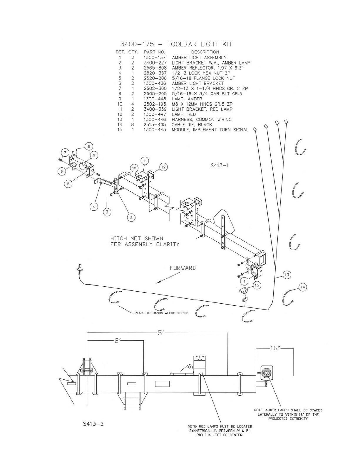
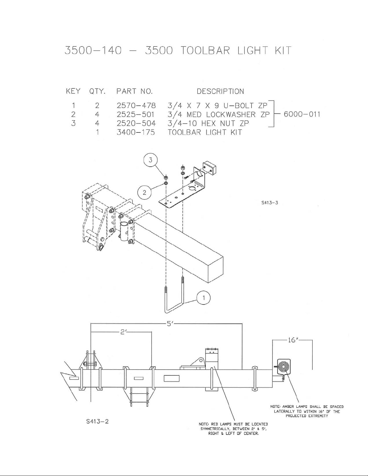
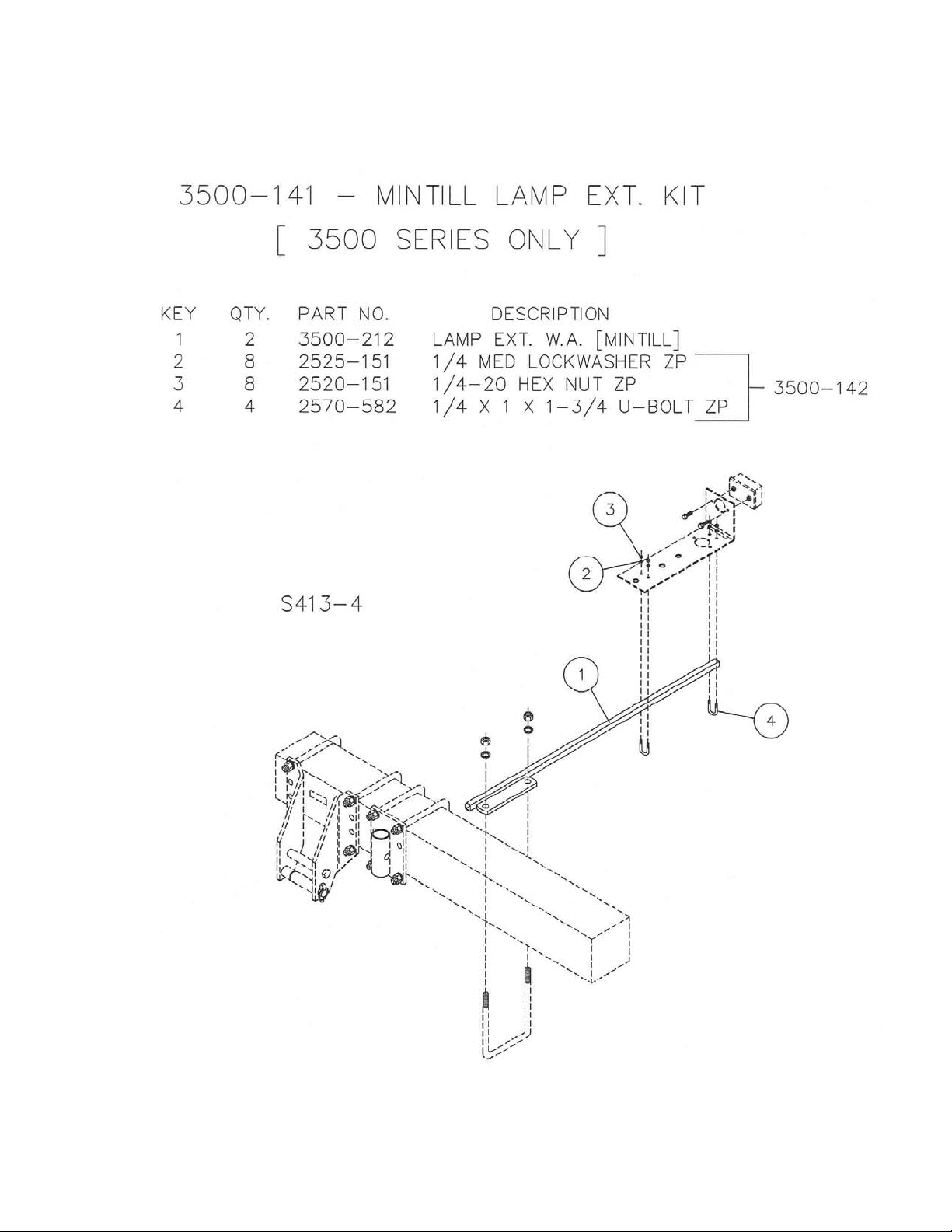
ASSEMBLY AND PARTS IDENTIFICATION
6
Page 7
ASSEMBLY AND PARTS IDENTIFICATION
7
Page 8
ASSEMBLY AND PARTS IDENTIFICATION
8
Page 9

3500 SERIES
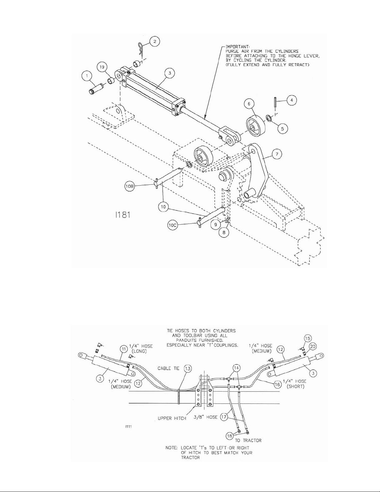
HYDRAULIC ASSEMBLY
ASSEMBLE HINGE LEVERS AS FOLLOWS
1. Drive a 3/8” x 2-1/2” roll pin into one end of each of 4 hinge pins.
2. On one wing of hoe assemble 1” washer on hinge pin, push pin thru near hole in hinge,
insert hinge lever, push pin thru other hole in hinge, assemble another 1” washer and roll
pin.
3. On other end of hinge lever assemble a 1” washer on hinge pin, put thru a wheel, push
rod clevis of a hydraulic cylinder, hinge lever, other side of clevis, wheel, washer, and
secure with another 3/8” roll pin.
4. On the butt end of cylinder remove 1 hairpin clip and the clevis pin, extend the cylinder
and fasten to the cylinder bracket with the clevis pin and the hairpin clip. Check spacing
between hinge lever and hinge bushing; (opposite zerk) and set to 1/8” to 3/16” spacing
by removing clevis pin and turning cylinder into or out of the rod end clevis. Tighten
clevis-clamping bolt.
5. Repeat 2, 3, and 4 for the remaining wing.
6. Lubricate the o-ring on each of the restricted 90-degree fittings and install into the cylinder
ports. DO NOT OVER TIGHTEN AND DISTORT THE METAL BACK-UP WASHER.
Position the fitting by turning it out (counter clockwise) to a maximum of one complete
turn and tighten the jam-nut.
7. There are four hose sizes as follows:
1. ¼” hose (short) 1 pc.
2. ¼” hose (medium) 2 pcs.
3. ¼” hose (long) 1 pc.
4. 3/8” hose, 2 pcs.
8. Connect a short and medium hose on opposite arms of a “T” fitting.
9. Connect a medium and long hose on opposite arms of a second “T”.
10. Position the short hose assembly on the toolbar with “T” on the operators left of the hitch
assembly, position the long hose assembly in the same manner, connect short hose ends
to the inner ports, the longer assembly to outer ports.
11. Connect the 4ft. 3/8” hoses to the remaining “T” ports and tighten ALL connections.
Adapters are provided for the hoses to connect to standard ¾-16 straight thread quick
coupler tips such as Case-IH part no. 1285718* or Deere part no. AR945222.
12. Using the cable ties furnished, tie the outer port hoses to the lower ends of each cylinder
and the hose to the toolbar on each side of the “T”s and at 2 to 3 foot intervals between.
13. IMPORTANT: Be sure to cycle the hydraulic cylinders before attaching them to the
folding wings. This removes air from the hoses and insures smooth wing operation.
CAUTION
STAND CLEAR OF FOLDING WINGS!
9
Page 10

HYDRAULIC ASSEMBLY
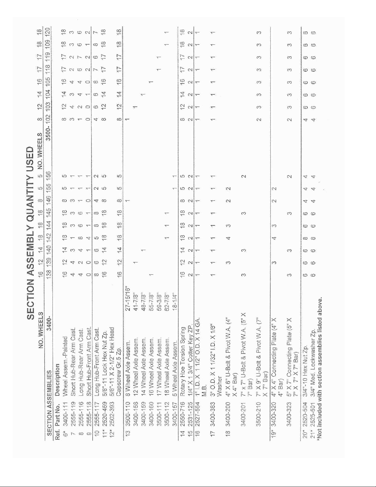
KEY QTY. PART NO. DESCRIPTION
1 2 2515-172 CLEVIS PIN FOR (3X16 & 4X16) CYLINDERS
3554-303 CLEVIS PIN FOR 5 X 16 CYLINDERS
2 4 2570-465 7 GA. X 3-3/4 HAIRPIN COTTER ZYD.
3 2 3500-387 3” X 16” ASAE CYLINDER, 1-1/4” ROD DIA., PAINTED
(3500 SERIES EXCEPT 3541 & 3546)
3500-388 4” X 16” ASAE CYLINDER (3541 & 3546)
2515-826 5” X 16” SAE-35016 CYLINDER, (54’ & 60’)
4 8 2530-208 3/8” X 2-1/2” ROLL PIN ZYD.
5 12 2527-564 1” ID X 1-1/2” OD X 14 GA. MACH BUSHING ZYD.
4 2527-561 1-1/4 ID X 2-1/4 OD X 14 GA. MACH BUSHING ZYD. (54’& 60’)
6 4 3500-390 HINGE WHEEL (1” ID X 4-3/8 OD)
4 3554-204 54’ HINGE WHEEL W.A. (54’ & 60’)(1.25 ID X 4.5 OD)
7 2 3500-226 HEAVY HINGE LEVER W.A. (1” PIVOT HOLES)
2 3560-200 60’ HINGE LEVER W.A. (1.5” AND 1.25” PIVOT HOLES)
2 3554-205 54 FT. HINGE LEVER W.A. (1” ID BUSHING, 1.25 CYL CLV)
8 4 2520-543 7/8-9 JAM HEX NUT ZYD.
9 4 2502-604 7/8-9 X 3-1/2” THREAD. TO HEAD TAP BOLT GR. 2 ZYD.
10 4 3500-308 HINGE PIN (1” D. X 8-3/4 LONG)
2 3560-301 60’ HINGE PIN UPPER (1.25 D. X 9.75 LONG)
10B 2 3554-310 HINGE LEVER PIN UPPER, (54’ & 60’)(1.25” D. X 8.75” LONG)
10C 2 3560-300 HINGE LEVER PIN LOWER, (54’ & 60’)(1.5” D. X 8.75” LONG)
11 1 2515-358 HOSE, ¼” X 50” W/-6 JIC ENDS (3521)
1 2515-362 HOSE, ¼” X 75” W/-6 JIC ENDS (3528 & 3530)
1 2515-364 HOSE, ¼” X 90” W/-6 JIC ENDS (3530 & 3534)
1 2515-366 HOSE, ¼” X 110” W/-6 JIC ENDS (3541)
1 2515-367 HOSE, ¼” X 135” W/-6 JIC ENDS (3546)
1 2515-397 HOSE, ¼” X 160” W/-6 JIC ENDS (3554)
1 2515-372 HOSE, ¼ X 200” (3560)
12 2 2515-356 HOSE, ¼” X 35” W/-6 JIC ENDS (3521)
2 2515-358 HOSE, ¼” X 50” W/-6 JIC ENDS (3528)
2 2515-360 HOSE, ¼” X 65” W/-6 JIC ENDS (3530)
2 2515-362 HOSE, ¼” X 75” W/-6 JIC ENDS (3534)
2 2515-365 HOSE, ¼” X 100” W/-6 JIC ENDS (3541)
2 2515-367 HOSE, ¼” X 135” W/-6 JIC ENDS (3546)
2 2515-387 HOSE, ¼” X 150” W/-6 JIC ENDS (3554)
2 2515-371 HOSE, ¼ X 180” (3560)
13 4 2515-405 CABLE TIES (3521)
6 CABLE TIES (3528, 3530)
8 CABLE TIES (3534)
10 CABLE TIES (3541, 3546)
12 CABLE TIES (3554, 3560)
14 2 2515-326 TEE FITTING, –6/-6/-6 JIC
15 4 2515-330 90 DEG FITTING, ¾” SAE TO –6 JIC, RESTRICTED
16 1 2515-353 HOSE, ¼” X 35” W/-6 JIC ENDS (3521)
1 2515-356 HOSE, ¼” X 50” W/-6 JIC ENDS (3528)
1 2515-358 HOSE, ¼” X 65” W/-6 JIC ENDS (3530)
1 2515-360 HOSE, ¼” X 75” W/-6 JIC ENDS (3534)
1 2515-365 HOSE, ¼” X 100” W/-6 JIC ENDS (3541)
1 2515-365 HOSE, ¼” X 100” W/-6 JIC ENDS (3546)
1 2515-366 HOSE, ¼” X 110” W/-6 JIC ENDS (3554)
1 2515-367 HOSE, ¼ X 135” (3560)
17 2 2515-386 HOSE, 3/8” X 50” W/-6 JIC ENDS
18 2 2515-327 ADAPTER, ¾ SAE TO –6 JIC
19 4 1000-361 13/16” UPPER SLEEVE, ZP. (54 FT. ONLY)
20 4 2515-827 REDUCER, (3554 & 3560)
3 X 16 SEAL KIT ROCKFORD/HYDRO-LINE 2515-338
COMMAND 2515-128(BLACK & YELLOW PISTON SEAL)
MONARCH 2515-338
PRINCE 1-1/8” ROD 2515-103
PRINCE 1-1/4” ROD 2515-265
4 X 16 SEAL KIT ROCKFORD/HYDRO-LINE 2515-468
COMMAND 2515-144
MONARCH 2515-170
5 X 16 SEAL KIT PRINCE 2515-171
10
Page 11
HYDRAULIC ASSEMBLY
FIGURE 1
11
Page 12
ASSEMBLY
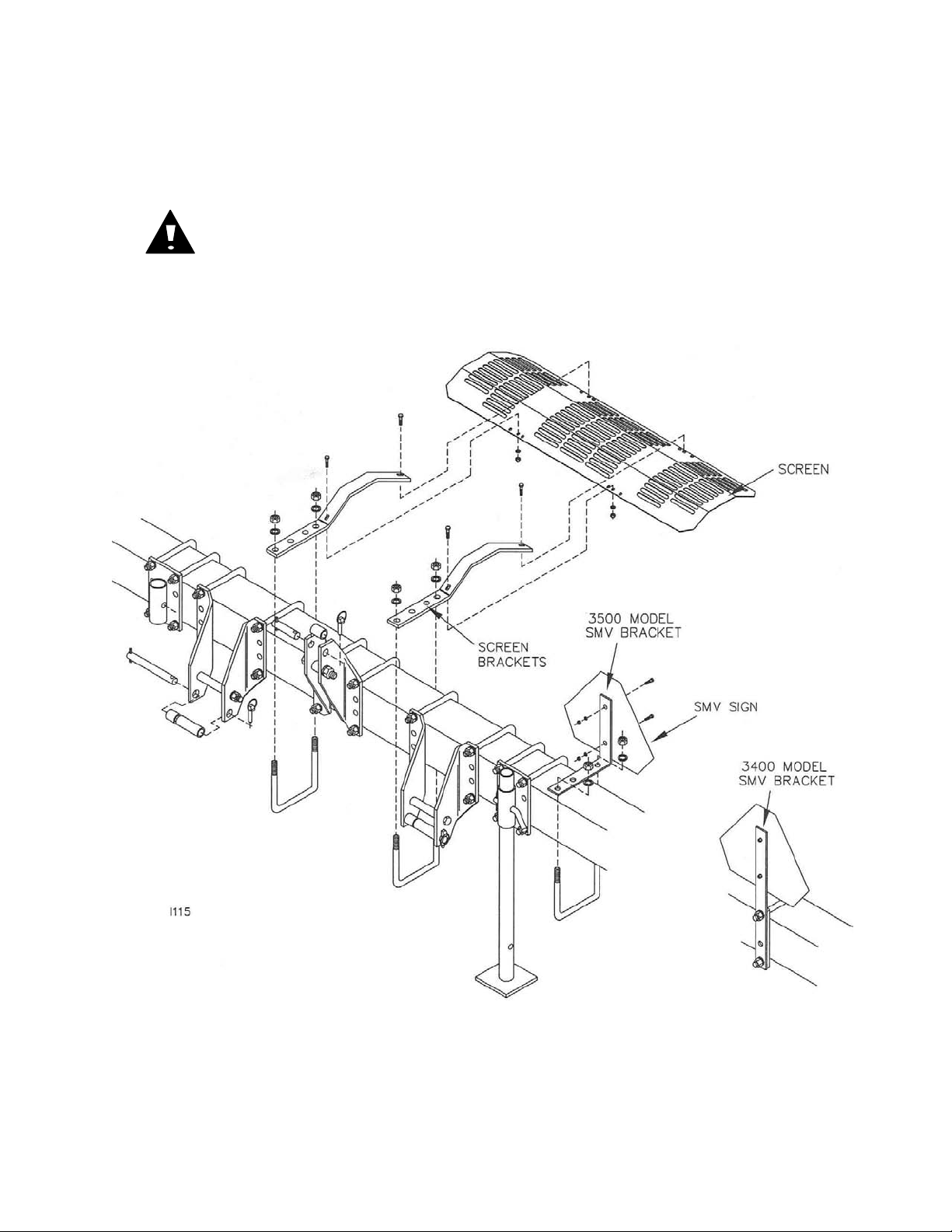
SCREEN ASSEMBLY
1. Assemble the screen brackets to the screen with four 3/8 x 1” bolts, lock washers,
and nuts.
2. Mount the screen assembly to the main frame as shown with two u-bolts, lock
washers, and nuts. Additional screens can be ordered if desired.
CAUTION: DO NOT OPERATE ROTARY HOE UNLESS SCREEN IS
SECURED AND PROPERLY INSTALLED.
SMV ASSEMBLY
1. Mount SMV emblem as shown with point of triangle up as near operators left of
center as possible. Face so emblem is visible from rear of equipment.
12
Page 13

ASSEMBLY
GAUGE WHEELS
Frame gauge wheels maintain the rotary hoe frame at a constant level in respect to the
ground contour, which helps insure uniform penetration of the hoe wheels. Recommended
tire size 7.50 x 14 or equivalent.
Mount the frame gauge wheels as shown, location each wheel an equal distance from the
center of the main frame. Gauge wheels should run outside the tractor wheel tracks.
To tighten wheel bearing, remove the hubcap and cotter pin. Tighten the slotted nut until
there is a slight drag on the bearing, while turning the wheel. Then loosen or back off the
slotted nut one slot and insert the cotter pin. There should be a slight drag on the bearing
following adjustment. Reinstall the hubcap.
CAUTION: ON 3500 MODELS, BEFORE ACTIVATING FOLDING HINGE
CHECK FOR OBSTRUCTIONS, ESPECIALLY CHECK GAUGE WHEEL
POSITIONS TO BE SURE THAT GAUGE WHEELS ARE SET TO CLEAR
TRACTOR AND OPERATOR.
CAUTION: CLEAR ALL PERSONNEL FROM AREA BEFORE FOLDING
OR UN-FOLDING TOOLBAR.
13
Page 14

OPERATION
ROTARY HOE PREPARATION
BOLTS AND NUTS:
Before starting to work, check all nuts and bolts for tightness.
HOE WHEELS:
Check all hoe wheels for straightness. Replace if necessary.
NOTE: ¼” of “RUNOUT” is acceptable.
LUBRICATION:
The basic Rotary Hoe requires no lubrication. If your hoe is equipped with gauge
wheels, repack the wheel bearings once a year with multi purpose lithium base
grease. On transport, axle straps need to be greased. Hinges on folding hoes
should be greased regularly.
TRACTOR PREPARATION
WHEEL SPACING:
Set the tractor wheels for the desired row spacing so the wheels are centered
between the rows. The distance from center of tractor to the center of the tire should
be the same on each side. Refer to your tractor operator’s manual for correct
inflation and ballast information of the tractor.
SWAY BLOCKS:
Place the sway blocks in the wide setting during transport to prevent any swaying of
the hoe.
DRAWBAR POSITION:
Place the drawbar in the short, center position to provide maximum clearance
between rear of drawbar and rotary hoe.
LIFT LINKS:
Adjust the length of lift links to maximum length. Refer to Tractor Operator’s Manual.
Keep an adequate distance between the tractor tires and rotary hoe toolbar.
If your hoe is equipped with gauge wheels, adjust the lift link pins to allow lateral float.
If gauge wheels are not used, adjust prevent any lateral float movement.
14
Page 15

ATTACHING ROTARY HOE TO TRACTOR
HITCH ASSEMBLY
The rotary hoe is shipped with mast and hitch pin bushings assembled for CAT III or IV hitches.
Remove bushings as required of your tractor.
Place sleeves and spacers in position to fit your hitch. The lower hitch plates are adjustable to fit your
tractor’s spacing.
CAUTION: BEFORE ATTACHING ROTARY HOE TO TRACTOR, BE
SURE HITCH PINS ARE COMPLETELY ASSEMBLED TO MATCH YOUR
TRACTOR HITCH.
TRACTOR WITHOUT QUICK COUPLER:
Attach rotary hoe to tractor with draft links to lower hitches.
Adjust the center link or extend the draft links to make hookup easier. Raise parking stand and place
in upper position.
TRACTOR WITH QUICK COUPLER:
Lower the 3-point hitch so the upper jaw of the Quick Coupler passes under the
spacer between the hoe mast plates. This allows lower jaws to pass under the hoe
hitch pins. Back tractor up until coupler jaws are under their respective pins and raise
hitch.
CAUTION: MAKE CERTAIN THAT CENTER LINK AND QUICK COUPLER
ARE LOCKED AND LOCK PINS ARE PROPERLY INSTALLED BEFORE
MOVING ROTARY HOE.
15
Page 16

FIELD OPERATION
PRE-OPERATION CHECK LIST:
Use this checklist each time you operate the hoe in the field. It will help you obtain
satisfactory field operation quickly.
1. Tractor sway blocks in upper position.
2. Center link adjusted for level frame in field operation.
3. Tractor lift links set in lateral float.
4. Tractor rockshaft control lever set in “zero”
5. Check hoe for loose or missing parts. Tighten hardware where necessary.
6. Bent hoe teeth straightened or replaced.
7. Hitch pins fastened and correct spacers used.
8. Quick couplers locked.
9. Adequate ballast added to front of tractor.
IMPORTANT: NEVER BACK UP WITH ROTARY HOE IN THE GROUND.
NEVER TURN WITH THE HOE IN ITS DOWN POSITION.
OPERATING SPEED:
An operating speed of 5 to 8 mph will normally provide the best results. Higher speeds
tend to increase the teeth penetration.
MAIN FRAME HEIGHT:
The mainframe height during field operation will normally be about 22 inches to bottom of
frame.
Without gauge wheels, set the tractor rockshaft control lever to obtain the desired frame
height.
With frame gauge wheels, put the rockshaft control lever all the way forward to lock “it” in
the float position, which will enable the frame gauge wheels to maintain the frame at a
uniform height from the ground.
LEVELING MAIN FRAME
Adjust lift links and center link as necessary to make hoe level and perpendicular to the
ground.
Before activating/folding hinge check for obstructions, especially check gauge wheel
positions to ascertain proper tractor and cab clearance.
NOTE: If gauge wheels are to be used, make leveling adjustments after gauge wheels
are installed.
16
Page 17

FIELD OPERATION
PARKING THE ROTARY HOES
3400 HOES
Lower the parking stand. Lower rotary hoe and loosen center link if necessary. Release
the latch levers and quick coupler, or raise center link latch handle and remove hitch pins,
then move tractor.
3500 HOES
Fold wings to the down position unless rear parking stand is used. Lower the parking
stands. Lower the rotary hoe and loosen center link if necessary. Release the latch
levers and quick coupler, or raise center link latch handle and remove hitch pins, then
drive tractor away.
CAUTION: NEVER UNHOOK FROM A FOLDED ROTARY HOE UNLESS REAR
PARKING STANDS ARE USED.
TRANSPORTING THE HOES
3400 HOES
To change from field to transport position, raise the hoe. Make certain the SMV symbol is
in place before transporting. DO NOT exceed 15 mph during transport.
3500 HOES
To change from field to transport position, raise the hoe, and then fold. Make certain
there is adequate clearance for the wings to fold without hitting obstructions. Check
gauge wheel positions for adequate tractor and cab clearance. Make certain the SMV
symbol is in place. DO NOT exceed 15 mph during transport.
CAUTION: STAND CLEAR OF FOLDING WING!
CAUTION: ALWAYS FOLLOW ALL STATE, FEDERAL, AND LOCAL LAWS
WHEN TRANSPORTING ROTARY HOE ON PUBLIC ROADS.
17
Page 18

PARTS IDENTIFICATION
18
Page 19

PARTS IDENTIFICATION
19
Page 20

PARTS IDENTIFICATION
20
Page 21

PARTS IDENTIFICATION
21
Page 22

PARTS IDENTIFICATION
22
Page 23

PARTS IDENTIFICATION
23
Page 24

PARTS IDENTIFICATION
24
Page 25

PARTS IDENTIFICATION
25
Page 26

26
Page 27
27
Page 28

I112-001-3
28
Page 29

MIN-TILL CONVERSION
This conversion kit increases the separation of the two rows of rotary hoe wheels improved
residue flow through.
1. Attach “stop” casting to each rear wheel arm with small u-bolt.
2. Remove hoe wheel from existing rear arm.
3. Attach arm extension casting to rear arms with existing wheel bolt and nut.
4. Attach hoe wheel to end to extension casting with bolt and lock nut supplied.
CAUTION: On the 3500 Series Folding Hoes that are being equipped with
the Mill-Till Conversion Kit (3400-170), the helper spring kit (3400-172)
must be added to the seven min-till arms above the OSHA screen in the
folding position. Failure to add helper spring will cause damage to the
OSHA screen.
29
Page 30
INSTALLATION INSTRUCTIONS
3500-107 Wing Lock Kit is designed to
fit Yetter 21’, 28’, 30’, 34’, 41’, 46’ and
54’ Rotary Hoe Flat Folding Toolbars.
To prevent wings from floating up in
certain operating conditions the Yetter
Wing Lock Kit will hold the wings in
horizontal position when desired. To
allow the wings to float, simply retract
the wing lift cylinders slightly. This
allows complete operator control from
the tractor seat to let the wings float up
or to lock them down.
INSTALLATION:
1. Remove hinge levers and replace
with 4100-205 hinge lever on 41’
hoes unless hinge levers have a
21/32” dia. hole added to mount
wing lock hooks.
2. Drill (2) 17/32” dia. holes (as shown)
in hinge wheel ramp on each side of
toolbar. (Holes are in strap after
3/1/82 mfg.)
3. Mount wing lock guides and wing
lock tabs (as shown) with ½-13 x 11/2” hex head cap screws, lock
washers, and nuts.
WING LOCK KIT
4. Mount wing lock hooks on hinge
levers (as shown) using 3500-386
bushing, 5/8-11 x 4” hex head cap
screw, flat washers, and lock nut.
Be sure hooks pivot freely after bolt
is tightened.
5. Level the wings with the lower
existing screw adjustment to hold
the wings straight with the center
section.
6. Cycle cylinders, disconnected from
hinge lever, to remove air from
hydraulic system before folding
wings.
7. Assemble cylinder and hinge wheels
as shown.
8. Extend the wing lift cylinders until
they bottom out. NOTE: This will
cause the wing lock hooks to yield
slightly as they are stretched into
position.
9. Fold wings a few times slowly while
watching the wing lock hooks to be
sure they are operating properly.
30
Page 31

PARTS IDENTIFICATION
3500-107 – WING LOCK KIT
KEY QTY. PART NO. DESCRIPTION
1 4 3500-374 WING LOCK HOOK, 1”
2 4 3500-377 WING LOCK GUIDE
3 4 3500-378 WING LOCK TAB
4 4 3500-386 BUSHING, 7/8 O.D. X .635 I.D. X 1-1/16
5 2 2502-336 5/8-11 X 4” HHCS GR 5 ZYD.
6 4 2502-301 ½-13 X 1-1/2 HHCS GR 2 ZYD.
7 4 2526-451 5/8 STD FLATWASHER ZYD.
8 2 2520-459 5/8-11 HEX LOCK NUT ZYD.
9 4 2520-352 ½-13 HEX NUT ZYD.
10 4 2525-352 ½ MED LOCKWASHER ZYD.
3500-135 – REAR PARKING STAND ASSEMBLY
KEY QTY. PART NO. DESCRIPTION
1 2 2570-478 ¾ X 7 X 9 U-BOLT ZYD.
2 2 3500-229 REAR PARKING STAND BRKT.
3 4 2525-501 ¾ MED LOCKWASHER ZYD.
4 4 2520-504 ¾-10 HEX NUT ZYD.
5 2 2502-336 5/8-11 X 4” HHCS GR 5 ZYD.
6 2 3500-230 REAR PARKING STAND W.A.
7 2 3500-384 PIVOT BUSHING, PARK STAND
8 2 2525-451 5/8 MED LOCKWASHER ZYD.
9 2 2520-452 5/8-11 HEX NUT ZYD.
10 2 3500-333 STAND PIN
11 2 2570-465 7 GA. HAIRPIN COTTER ZYD.
31
Page 32

PARTS IDENTIFICACTION
32
Page 33

PARTS IDENTIFICATION
3560-112
33
Page 34

PARTS IDENTIFICATION
INSTALLATION INSTRUCTIONS
1. Install trash guard to arm casting with trash
guard tip towards rear of hoe using ¼ u-bolts,
nuts and lock washers as shown. NOTE: Do
Not tighten bolts at this time.
2. Set depth of hoe and adjust trash guards.
Recommended setting: Tip of trash guard
should be 1” to 1-1/2” from ground, depending
on field conditions when hoe wheel is
penetrating.
3. Tighten all u-bolts after adjusted.
4. The trash guard does not work on the Min-till
Arm Extension Kit.
3400-147 – TRASH GUARD ASSEMBLY
KEY QTY. PART NO. DESCRIPTION
1 1 3400-225 TRASH GUARD W.A.
2 2 2570-481 TRASH GUARD U-BOLT
3 4 2525-151 ¼ MED LOCKWASHER ZYD.
4 4 2520-151 ¼-20 HEX NUT ZYD.
INSTALLATION INSTRUCTIONS
1. Install the torsion spring (#5) and anchor spring
(#6) over existing spring and axle. Hook to spring
bracket (#7).
2. Assemble the spring clamp casting (#3) and clamp
plate (#2) to spring using 5/16 x 1” bolt and nut
inserted in clamp casting. Preset lower hook 2” to
3” in front of arm that it is being installed on.
Tighten clamp then pull hook up on arm and spring
tension is preset.
3400-172 – HELPER SPRING SHIP ASSEMBLY
KEY QTY. PART NO. DESCRIPTION
1 1 2502-198 5/16-18 X 1 HHCS GR 5 ZYD.
2 1 3400-391 CLAMP PLATE
3 1 3400-392 CLAMP
4 1 2520-205 5/16-18 LOCK HEX NUT ZYD.
5 1 3400-393 TORSION SPRING
6 1 3400-394 ANCHOR SPRING
7 1 3400-375 SPRING BRACKET
34
Page 35

Problem
Premature bearing failure
Rotary hoe arm bending or breaking
3500 Series Wings float up
Hydraulic cylinders fail to operate
properly (3500 model only)
Rotary hoe wheels plug with trash
materials
Hoe wheels won't penetrate
Rotary hoe wheels are too aggressive
TROUBLE SHOOTING
Cause
Excessive strain on the hoe wheel
bearings
Excessive strain on the arms and
wheels
Air in system
Gauge wheels not properly adjusted
Wing deflection not properly adjusted
Hinge levers not properly installed
Hydraulic system improperly installed
Air in system
Blocked restrictors
Excessive trash conditions
Hard soil conditions
Rotary hoe wheels running too fast
Rotary hoe wheels running too deep
Solution
Don't turn with rotary hoe wheels on
the ground
Store the rotary hoe inside to help
protect the bearings from freezing
weather, moisture, blowing sand, and
dirt
Keep all wheel bolts tight. Check
rotary hoe wheels for loose rivets and
bent teeth. Check for bent arm
castings
Don't turn with the rotary hoe wheels
on the ground
Don't back the rotary hoe with wheels
on the ground
Check for air in hydraulic system and
purge system
Check proper adjustment of wing
gauge wheels
Maintain center tool bar height above
or parallel with outer wings
Check assembly of hinge levers
Install 3500-107 Wing Lock Kit
Check for correct assembly of the
hydraulic system
Check for air in the hydraulic system
and purge system
Check restrictors for malfunctions
Decrease operating depth of hoe
wheels and increase ground speed to
create momentum so the hoe wheels
may clean themselves
On softer, mellow soils, decrease
operating depth so that hoe wheels
do not pickup trash material
Install optional Min-Till Conversion
Kit, (3412-3434-125)(3541or3546-
125)
Install optional trash guard (part no.
3400-147)
Lower tool bar to maximize
aggressiveness of rotary hoe
Lengthen center link on tractor to tilt
tool bar back to increase spring
tension
Install optional helper spring (part no.
3400-150)
Slow tractor ground speed
Decrease operating depth of rotary
hoe wheels
Install toolbar gauge wheels except
on model 3412 and 3415
35
Page 36

Our name
Is getting known
Just a few years ago, Yetter products were sold primarily to the
Midwest only. Then we embarked on a program of expansion and
moved into the East, the South, the West and now north into Canada.
We’re even getting orders from as far away as Australia and Africa.
So, when you buy Yetter products . . .you’re buying a name that’s
recognized. A name that’s known and respected. A name that’s
become a part of American agriculture and has become synonymous
with quality and satisfaction in the field of conservation tillage.
Thank you.
YETTER MANUFACTURING CO.
Colchester, IL 62326-0358 • 309/776-4111
Toll Free 800/447-5777
Fax 309/776-3222
Website: WWW.YETTERCO.COM
E-MAIL: INFO@YETTERCO.COM
2565-118_REV_E • 02/12
36
 Loading...