

Page 1

2995 XFC Fertilizer Coulter
2995 XCC Cutting Coulter
OPERATORS MANUAL
WITH PARTS IDENTIFICATION
YETTER MANUFACTURING CO.
FOUNDED 1930
Colchester, IL 62326-0358
Toll free: 800/447-5777
309/776-3222 (Fax)
Website: www.yetterco.com
E-mail: info@yetterco.com
2565-788_REV_B ● 11/2018
Page 2

FOREWORD
You’ve just joined an exclusive but rapidly
growing club.
For our part, we want to welcome you to the
group and thank you for buying a Yetter product.
We hope your new Yetter products will help you
achieve both goals-increase your productivity and
increase your efficiency so that you may generate
more profit.
This operator’s manual has been designed into
four major sections: Foreword, Safety
Precautions, Installation Instructions and Parts
Breakdown.
This SAFETY ALERT SYMBOL indicates
important safety messages in the manual.
When you see this symbol, be alert to the
possibility of PERSONAL INJURY and
carefully read the message that follows.
The word NOTE is used to convey information
that is out of context with the manual text. It
contains special information such as
specifications, techniques and reference
information of a supplementary nature.
The word IMPORTANT is used in the text when
immediate damage will occur to the machine due
to improper technique or operation. Important will
apply to the same information as specified by
note only of an immediate and urgent nature.
It is the responsibility of the user to read the
operator’s manual and comply with the safe and
correct operating procedure and to lubricate and
maintain the product according to the
maintenance schedule in the operator’s manual.
The user is responsible for inspecting his
machine and for having parts repaired or
replaced when continued use of the product
would cause damage or excessive wear to the
other parts.
It is the user’s responsibility to deliver his
machine to the Yetter dealer who sold him the
product for service or replacement of defective
parts, which are covered by the warranty policy.
If you are unable to understand or follow the
instructions provided in this publication, consult
your local Yetter dealer or contact:
YETTER MANUFACTURING CO.
309/776-4111
800/447-5777
309/776-3222 (FAX)
Website: www.yetterco.com
E-mail: info@yetterco.com
WARRANTY
Yetter Manufacturing warrants all products manufactured and sold by it against defects in material. This
warranty being expressly limited to replacement at the factory of such parts or products as shall appear to
be defective after inspection. This warranty does not obligate the Company to bear cost of labor in
replacement of parts. It is the policy of the Company to make improvements without incurring obligations to
add them to any unit already sold. No warranty is made or authorized to be made, other than herein set
forth. This warranty is in effect for one year after purchase.
Dealer ___________________________________________________
Yetter Manufacturing warrants its own products only and cannot be responsible for damages to
equipment on which mounted.
2
Page 3

SAFETY
A brief description of signal words that may be used in this manual:
CAUTION: Used as a general reminder of good safety practices or to direct attention to unsafe
practices.
WARNING: Denotes a specific potential hazard.
DANGER: Denotes the most serious specific potential hazard.
SAFETY PRECAUTIONS
You can make your farm a safer place to live and work if you observe the safety precautions given. Study
these precautions carefully and insist that they be followed by those working with you and for you.
Finally, remember this: an accident is usually caused by someone’s carelessness, neglect, or oversight.
WARNING
Never clean, lubricate or adjust a machine that is in motion. Always lower or block the implement before
performing service.
If machine must be serviced in the raised position, jack or block it up to prevent it from accidentally falling
and injuring someone.
Do not allow riders on the tractor or implement.
Use speeds and caution dictated by the terrain being traversed. Do not operate on any slope steep enough
to cause tipping or loss of control.
Be sure all personnel are clear of the immediate area before operating.
Read and understand the operator’s manual and require all other persons who will operate the equipment
to do the same.
Be familiar with all tractor and implement controls and be prepared to stop engine and implements quickly in
an emergency.
CAUTION
Consult your implement and tractor operator’s manual for correct and safe operating practices.
Beware of towed implement width and allow safe clearance.
FAILURE TO HEED MAY RESULT IN PERSONAL INJURY OR DEATH.
3
Page 4
GENERAL INFORMATION
4
Page 5
GENERAL INFORMATION
5
Page 6
6
Page 7
7
Page 8

MAINTENANCE
•
After a few hours use, check all bolts and setscrews for tightness.
•
After using a few hours, check for loose hardware, re-tighten as needed.
•
After a few days use, check coulter hubs for loose bearings. There should be no end play in the hub
bearings to allow it to wobble. If necessary, remove hub cap and cotter pin, adjust slotted nut to remove
wobble, re-insert cotter pin and replace hub cap.
LUBRICATION
DANGER: Always install safety lock-ups or lower the planter to the ground before working on the machine.
Lubricate at frequency indicated with a multi-purpose type grease.
ISO 2995-086
DANGER: Always install all safety lock-ups and safety lock pins before working under the toolbar.
1. Raise the toolbar until is clear off the ground. Remove the gauge wheel and the blade. Remove the hubcap,
cotter pin, slotted nut and washer from the spindle shaft assembly.
2. Pull the coulter spindle shaft assembly from the hub. Remove bearing cones and cups and discard if bearings
are being replaced. Clean hub and dry. Remove bearings only and not cups of re-packing.
3. Wash the old grease from the hub, bearing cups, coulter spindle shaft, seal, and bearing cones. Inspect the
condition of bearing cups and cones.
4. Apply #2 multi-purpose lithium grease on each bearing. Make sure the space around each roller is filled.
Lubricate the bearing cups.
5. Position the bearing in the cup and install the seal. Lubricate the seal lips and proceed with re-assembly of the
removed parts including the blade. Blade bolt torque is 90 to 96 ft. lbs.
6. Install outer bearing, washer, and slotted nut. Tighten the slotted nut to 150 in. lbs. while rotating the blade or
until a definite drag is felt when the blade is turned by hand. Tighten the nut one slot position to line up the
cotter pin hole with a slot. Secure the nut with a new cotter pin.
8
Page 9
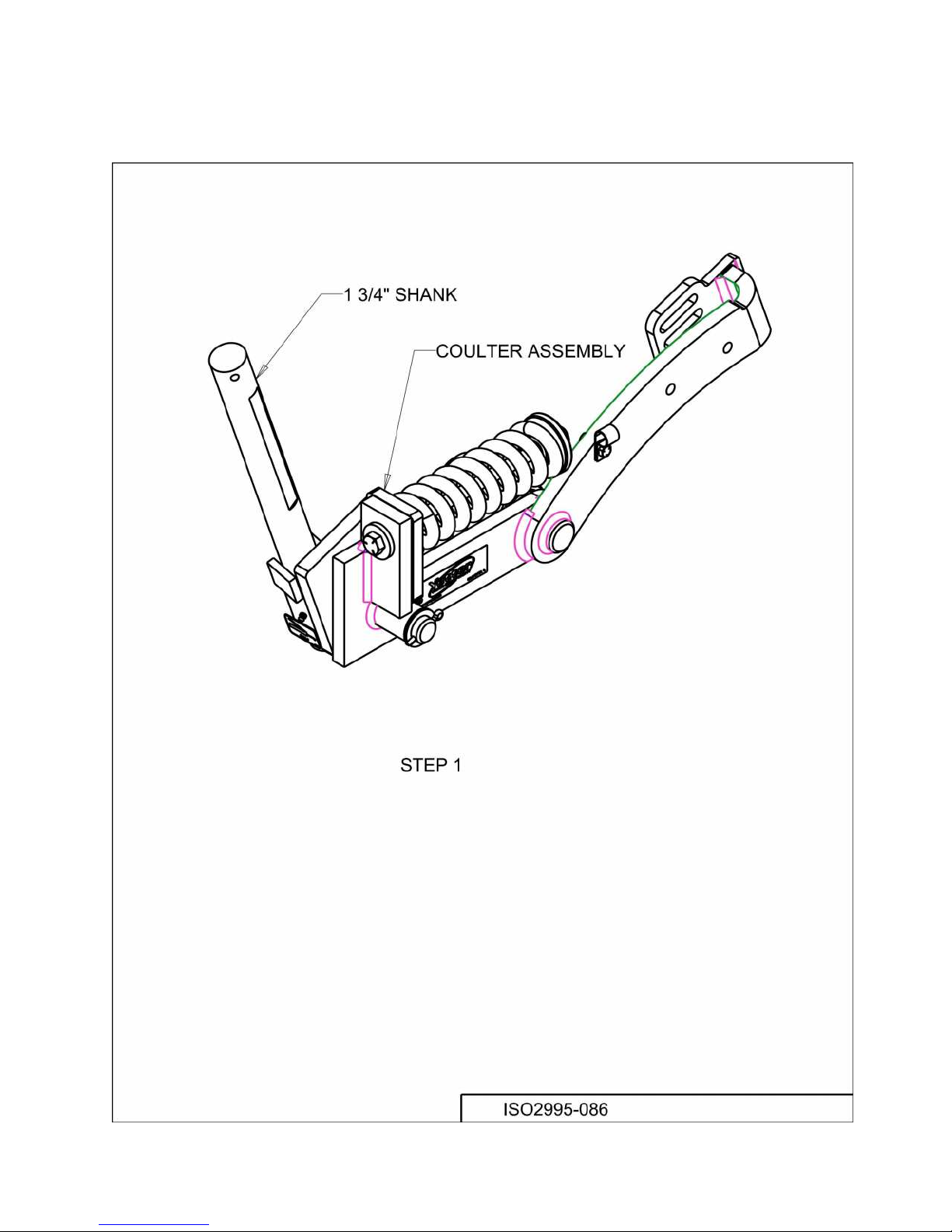
ASSEMBLY INSTRUCTIONS
STEP 1. Install shank to the coulter assembly.
9
Page 10

ASSEMBLY INSTRUCTIONS
STEP 2. Install roll pin to the shank.
10
Page 11
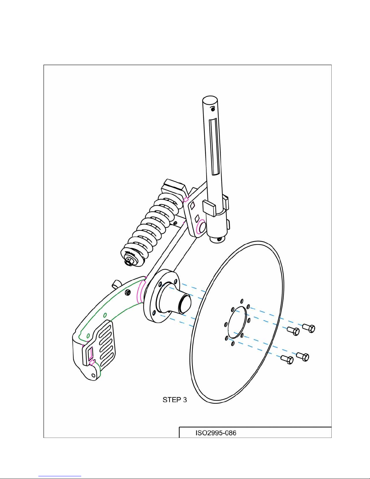
ASSEMBLY INSTRUCTIONS
STEP 3. Attach the blade to the coulter assembly using the 4) ½” – 20 X 1” Hex Head
Bolts.
11
Page 12

ASSEMBLY INSTRUCTIONS
STEP 4. Attach the toolbar clamp to the frame.
12
Page 13

ASSEMBLY INSTRUCTIONS
STEP 5. Loosely assemble the set screws and lock nuts to the toolbar clamp.
13
Page 14

ASSEMBLY INSTRUCTIONS
STEP 6. Slide shank into the toolbar clamp. Install roll pin to the shank.
14
Page 15

ASSEMBLY INSTRUCTIONS
STEP 7. Adjust coulter shank up or down as needed to securely tighten 2) set screws.
STEP 8. If using fertilizer, install the injector or knife as shown in the parts identification
section of this manual.
15
Page 16

PARTS IDENTIFICATION
16
Page 17

PARTS IDENTIFICATION
17
Page 18

PARTS IDENTIFICATION
COULTER ASSEMBLY
2995-197-RH
18
Page 19

PARTS IDENTIFICATION
COULTER ASSEMBLY LH
2995-197-LH
19
Page 20

PARTS IDENTIFICATION
20
Page 21

PARTS IDENTIFICATION
COULTER ASSEMBLY
2995-153
21
Page 22

PARTS IDENTIFICATION
22
Page 23

PARTS IDENTIFICATION
2995-149
23
Page 24

PARTS IDENTIFICATION
2995-138
24
Page 25

PARTS IDENTIFICATION
25
Page 26

PARTS IDENTIFICATION
26
Page 27

PARTS IDENTIFICATION
27
Page 28

PARTS IDENTIFICATION
28
Page 29

PARTS IDENTIFICATION
29
Page 30

PARTS IDENTIFICATION
30
Page 31

PARTS IDENTIFICATION
31
Page 32

TROUBLESHOOTING
32
Page 33

NOTES:
33
Page 34

NOTES:
34
Page 35

NOTES:
35
Page 36

Our name
Is getting known
Just a few years ago, Yetter products were sold
primarily to the Midwest only. Then we embarked on a
program of expansion and moved into the East, the
South, the West and now north into Canada. We’re even
getting orders from as far away as Australia and Africa.
So, when you buy Yetter products . . .you’re buying a
name that’s recognized. A name that’s known and
respected. A name that’s become a part of American
agriculture and has become synonymous with quality and
satisfaction in the field of conservation tillage.
Thank you.
YETTER MANUFACTURING CO.
Colchester, IL 62326-0358 309/776-4111
Toll Free 800/447-5777
Fax 309/776-3222
Website: www.yetterco.com
E-mail: info@yetterco.com
2565-788_REV_B
11/2018
36
 Loading...