

Page 1
Heat Pump Kit 5/16”
61040
Manual for Operation
OMNI™ Vacuum Gauge Operating Instructions:
1. Press the ON/OFF button to power on the gauge.
2. To manually power off the gauge, press and hold the ON/OFF button until
the screen displays the “YJ” logo.
3. To change a setting:
• Tap the corresponding button to highlight the current setting
• Continue to tap this button until the desired value is displayed
• Press and hold this button to confirm the new setting – the highlighting
will disappear when the setting has been confirmed
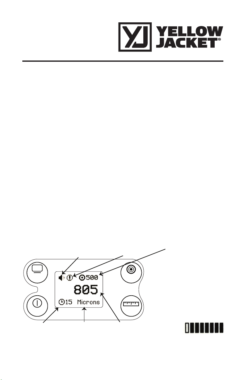
DISPLAY: Select from several notification options. To change the background, press and hold for three seconds to inverse LCD mode.
ON/OFF: Power on and off, select from four different auto-off settings.
Target Vacuum
Level
*TARGET - Select from five
preset vacuum level targets.
*UNITS - Select from four
different vacuum units.
DISPLAY
ON/OFF
Auto-Off Timer
(in minutes)
Audio
Notification
Vacuum
Unit
Notification
Icon
TARGET
UNITS
Vacuum Level (displays bar
graph until deep vacuum reached)
Page 2

Single Valve Manifold Connection Guide
Reading System Pressure
1. Ensure both the ball valve and manifold
valve are in the closed position
2. Connect the 5/16” ball valve to the
system
3. Open system valve
4. Open ball valve
5. Purge non-condensable gas from hose
fitting at manifold fitting
6. Read system pressure
Adding Refrigerant Charge
1. Open the manifold valve, but leave the
ball valve closed
2. Connect the 1/4” flare end of the long
hose to the refrigerant cylinder
3. Connect the 5/16” ball valve hose to
the system
4. Open the valve on the refrigerant tank
5. Purge non-condensable gas from 5/16”
fitting
6. Open system valve
7. Open the ball valve until desired charge
is achieved
8. Close tank refrigerant valve
9. Allow system to pull remaining liquid
out of hoses
10. Close ball valve and manifold valve,
disconnect from system and refrigerant
tank
Page 3
Single Valve Manifold Connection Guide – continued
Drawing Vacuum on the System
1. Connect core removal tool to system.
2. Use built in Schrader valve tool to
remove core, set aside for re-use, or
replace with fresh core once evacuation
is complete.
3. Close 4 in 1 ball valve
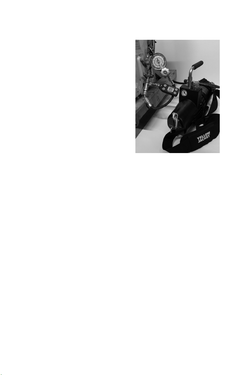
4. Connect OMNI™ Digital Vacuum Gauge
to side port of core removal tool
5. Connect manifold, hoses, and vacuum
pump to end of core removal tool
6. Turn on vacuum pump and allow to run
until desired vacuum is reached
7. Close ball valve on core removal tool,
disconnect vacuum pump, and shut off
8. Conduct hold test until desired duration
is complete
9. Remove OMNI™ Digital Vacuum Gauge
from side port
10. Proceed to charge the system as indicated in the “Adding Refrigerant to the
System” section, using the side port of
the core removal tool to connect the ball
valve to the system
11. Insert Schrader core into core tool
12. Connect core tool to ball valve end of
core removal tool
13. Open ball valve, insert Schrader core
and tighten to between 3-5 in-lbs
14. Remove core removal tool from system
Page 4
Replacement Parts
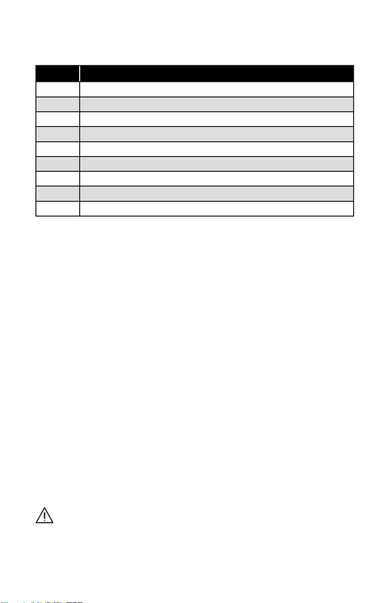
UPC # DESCRIPTION
40346 Heat Pump Manifold R-410A/R32 °F and °C Single Valve
49142 Replacement Heat Pump Gauge R-410A/R32 °F and °C
29491 Heavy Duty 12” Hose with 1/4” x 5/16” Ball Valve
15024 Heavy Duty 24” Hose with 1/4” x 1/4” 45° BLACK
18985 5/16” Core Removal Tool
69239 Digi-Alarm Thermometer
60295 Eccentric Cone Flaring Tool
69021 OMNI™ Digital Vacuum Gauge 5/16” Fitting
61045 Custom Foam Carrying Case
• One-year warranty
• MADE IN USA
WARNING: This product can expose
you to lead, which is known to the
State of California to cause cancer
and birth defects or other reproductive
harm. For more information go to
www.P65Warnings.ca.gov.
Ritchie Engineering Company, Inc.
YELLOW JACKET® Products Division
10950 Hampshire Avenue South
Bloomington, MN 55438-2623 USA
Phone: (800) 769-8370 or (952) 943-1300
e-mail: [email protected]
www.yellowjacket.com
PN 701147 RevB
 Loading...