

Y-E Data YD-380 Maintenance Manual

VY·E
DATA
HALF
MAINTENANCE
YD-380
HEIGHT,
5.25
INCH
HIGH
FLEXIBLE
MANUAL
DENSITY,
DISK
DOUBLE
DRIVE
SIDED
Contents
Check
the
of
this
revision
manual
number when
may
be
changed
placing
September
FDL-523006
without
an
order.
notice.
1983
REV.
A

Revisions
Date
..
~ptember
.
-
--
-
--
---
-
-
-
-
83
Rev.
A
Description
First
Edition
Revised
Pages
~ote:
I~"
('21
publication
----~e
~=~e
~
-.
disk.
YD-380
5.25
may
inch
be
referred
flexible
disk
to
may
as
simply
be
referred
a
"drive".
to
as
simply
YD-380
Maintenance Manual
TABLEOFCONTENTS
Page
1.0
2.0
3.0
4.0
INTRODUCTION
MAINTENANCE
2.1
Maintenance Tool
2.2
Maintenance
2.3
2.4
Test
Exerciser
PREVENTIVE
3.1
General
3.2
Visual
3.3
Cleaning
SERVICE
TOOLS
Equipment
MAINTENANCE
Check
CHECKS,
AND
TEST
EQUIPMENT
List
Supplies
REPLACEMENT
List
AND
ADJUSTMENT
1
1
1
2
2
2
3
3
3
3
4
Maintenance
4.1
4.2
4.3
4.4
4.5
4.6
PWB
Index
Track
Write
Media
In
Use
Level
1
Sensor Assembly
00
Sensor
Protect
Assembly
Sensor
Sensor Assembly
Lamp
Assembly
Assembly
5
6
9
11
12
14

TABLEOFCONTENTS
Page
5.0
6.0
~Aintenance
4.7
4.8
4.9
4.10
4.11.
4.12
4.13
4.14
Carrier
Index
Drive
Head Load
Front
Front
Stepper
Head/Carriage
Level. 2
Assembly
Lamp
Motor Assembly (on Motor
Lever
Bezel
Assembly
PARTS/ASSEMBLIES
TEST
POINT/CONNECTOR
Assembly (on Motor
Solenoid
Assembly
PHYSICAL
PIN
LOCATIONS
ASSIGNMENTS
Control
Control
PWB)
PWB)
15
16
17
18
21
U
23
24
30
35 .
7.0
8.0
9.0
10.0
SPARE
PARTS
SCHEMATIC
EXPLODED
USINGACLEANING
LIST
DIAGRAMS
VIEW
DISK
38
39
42
43

1.0
INTRODUCTION
This
DATA
Included
ment
engineers.
2.0
MAINTENANCE
The
supplies,
2.1
Maintenance
Phillips
manual
YD-380
is
procedures,
following
test
Screwdriver
describes
two
sided,
information
and
TOOLS
Tools
TOOL
AND
tables
equipment and
List
the
high
also
TEST
list
(for
maintenance
density,
on
service
adjustment
EQUIPMENT
the
maintenance
exerciser
M3)
and
5.25
checks,
instructions
tools,
for
Y-E
141034-01
operation
inch
Floppy
removal and
for
maintenance
the
YO-38D.
DATE
PIN
of
the
Disk
replace-
customers'
Y-E
Drive.
Phillips
Flat
Cutters
Needle Nose
Tweezers
CE
Disk
Cleaning
Wrench
Hex
Wrench
Hex
Screwdriver
Head
Disk
Screwdriver
Pliers
1.27
1.5
mm
mm
(for
M2.6)
141627-01
141035-01
141039-01
141040-01
141042-01
145173-01
145174-01
140266-03
140266-01

2.2
Maintenance
Supplies
2.3
Tie
Wrap
Test
Equipment
Test
Multimeter
Electronic
Oscilloscope*
*
For
Supplies
(TY-23M,
Equipment
Counter*
use
at
Kitagawa)
Maintenance
Level
Y-E
DATA
031005-01
2
PIN
2.4
Exerciser
Equipment
Exerciser
Y-E
DATA
YD-164T
PIN
3
.0
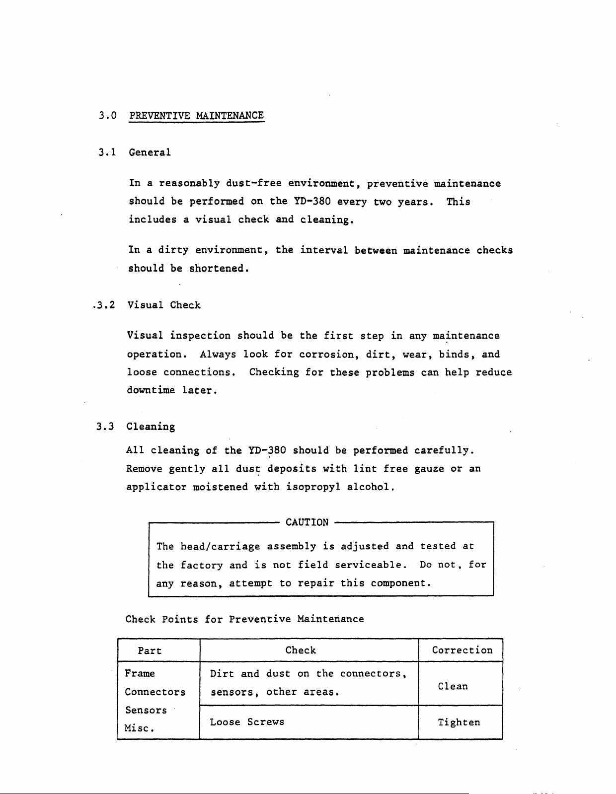
PREVENTIVE
MAINTENANCE
.
3.2
3.3
3.1
General
Inareasonably
should
includes
Inadirty
should
Visual
Visual
operation.
loose
downtime
be
performed
a
visual
environment,
be
shortened
Check
inspection
Always
connections.
later.
Cleaning
dust-free
on
check
•
should
look
Checking
environment,
the
YD-380
and
cleaning.
the
interval
be
the
for
corrosion,
for
every
first
these
preventive
two
between
step
dirt,
problems
maintenance
years.
maintenance
in
any
ma~ntenance
wear,
can
This
binds,
help
checks
and
reduce
All
cleaning
Remove
gently
applicator
The
the
any
Check
Points
Part
Frame
Connectors
Sensors
Misc.
of
the
all
dus~
moistened
head/carriage
factory
reason,
for
Dirt
and
attempt
Preventive
and
sensors,
Loose
YD-380
deposits
with
assembly
is
not
dust
other
Screws
should
isopropyl
CAUTION
field
to
repair
Maintenance
Check
the
on
areas.
be
performed
with
lint
alcohol.
is
adjusted
serviceable.
this
connectors,
carefully.
free
and
gauze
tested
Do
component.
or
an
at
not,
for
Correction
Clean
Tighten

4.0
SERVICE
CHECKS,
REPLACEMENTS
AND
ADJUSTMENTS
This
assemblies
two
Levell:
Level
Level
chapter
maintenance
2:
1
4.1
4.2
4.3
4.4
4.5
4.6
Level 2
4.7
contains
listed
Can
be
Special
PWB
Index
Track
Write
Media
In
Use
Carrier
below.
levels:
performed
training
Sensor
00
Sensor
Protect
Sensor
Lamp
detailed
Note
Sensor
maintenance
that
without
and
tools
the
list
special
required.
procedures
is
separated
training
or
for
the
into
tools.
Note:
4.8
4.9
4.10
4.11
4.12
4.13
4.14
Index
Drive
Head Load
Front
Front
Stepper
Head/Carriage
Refer
Chapter
Chapter9for
to
Lamp
Motor (on Motor
Lever
Bezel
Chapter
6
for
(on Motor
Solenoid
Assembly
5
for
Test
Exploded View.
Points/Connector
Control
Control
Parts/Assemblies
PWB)
PWB)
Pin
Locations,
Assignments and
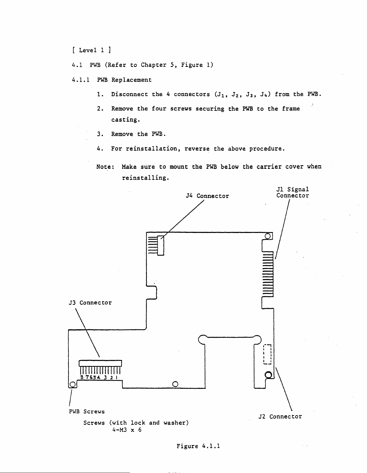
[
Levell]
4.1
4.1.1
PWB
PWB
1.
2.
3.
4.
Note:
(Refer
Replacement
Disconnect
Remove
casting.
Remove
For
to
reinstallation,
Make
reinstalling.
Chapter
the
the
four
the
PWB.
sure
5,
4
connectors
screws
to
mount
Figure
securing
reverse
the
J4
1)
(J1,
the
PWB
below
Connector
J2'
the
PWBtothe
above
the
J3,
J4)
procedure.
carrier
from
the
frame
cover
Jl
Signal
Connector
PWB.
when
J3
Connector
I
PWB
Screws
Screws
(with
4-M3
lock
x 6
and
o
washer)
Figure
4.1.1
,--,
I ,
, I
, :
I ,
--
J2
Connector

4.2
Index
Sensor
Assembly
(Refer
to
Chapter
5,
Figure
3)
4.2.1
4.4.2
Service
1.
2.
Replacement
1.
2.
3.
4.'
Check~
Power
Without
and
check
All
and G
the
vol
Remove
Remove
4.2.2)
Take
cover.
Lift,
out
up
up
the
inserting
for
tage
the
J3
connector
the
'
the
drive.
a
(GND).
at
PWB
carrier
lead
a
to
0.5
Next,
the
same
(Refer
clamps
disk,
V
between
insert
points
to
4.1)
housing
cover
slightly
move
6.
screws
the
lever
the
a
disk
should
(Refer
and remove
and
to
PWB
connector
and
be
2.5
to
pullout
lock
close
Page
to'
the
the
position
the
5.25
9,
figure
carrier
leads.
J3
door;
V'.
Pin
5.
6.
7.
8.
9.
Note:
Remove
Take
bly,
Take
and
sensor
When
lead
For
Perform
out
and remove
out
as
clamping
insulation.
reinstallation,
Make
arm
the
In
the
the
shown
assembly
a
service
sure
securing
the
Use Lamp.
screws
the
screws
in
figure
by
pushing
the
leads,
check.
front
the
for
the
front
to
CAUTION
reverse
Ready/Off
lever
the
4.4.1,
be
(See
edge
Write
in
front
and
remove
the
careful
the
above
4.l.l)
of
the
plate
lever
carrier
Protect
the
direction
not
procedure.
carrier
does
and
Sensor
write
to
damage
plate
not
carrier
assembly.
assembly,
protect
indicated.
the
spring
come
in
assem-
contact
with
the
leads.

Carrier
Spring
Plate
Front
Bezel
Side
Index
(with
Sensor
lock
M3x6)
Screw
and
washer,
Collet
Connector
Number
Guide
J3
---t--~
Connector
Housing
Figure
~ssignment
4.2.1
Lead Clamp
Collet
Shaft
Figure
4.2.2
Connector
No.
1
2 Head Load
3
4
5
6
7
8 Media
Stepper
Drive
Write
In
Use
Index
Track
Part
Solenoid
Motor
Protect
Lamp
Sensor
00
Sensor
Sensor
Sensor

4.2.3
Adjustment
1.
Loosen
2.
Power
3.
Connect
up
the
the
an
Index
Sensor
drive.
oscilloscope
screws
to
the
one
PWB
quarter
test
turn.
points
lA,
1B,
3.
Connect
connect
Set
the
INPUT
VERT
INVERT
TIME/DIV
VOLTS/DIV
4.
Insert
5.
Load
head/carriage
tion
signal
channell
the
external
oscilloscope
COUPLING
MODE
(CH
2)
(CHI,
a
CE
Disk
the
read/write
until
the
from TP3) and
to
controls
MODE
CH2)
and
heads
assembly
timing
PWB
TP
scope
AC
ADD
ON
0.1
100
turn
to
between
the
first
lA,
trigger
as
follows:
ms
mV
the
front
against
track
the
channel
the
2.
start
part
to
TP3.
lever
disk
Adjust
of
the
2
of
to
to
and
the
the
index
TP
lock
step
sensor
sweep
IB, and
position.
t~e
posi-
(index
burst
(TP
lA,
Index
Burst
(TP1A,TP1B)
Note:
TP
Signal
Signal
To
delay
front
lB)
is
within
(TP3)--------~
-600
Figure
the
bezel
Ind~x
(see
Burst,
Page
to
,....
4.2.3
9,
1400
move
figure
~s.
.,,..
-600
the
4.2.1).
1 _
to
1400~s
J
sensor
towards
the

6.
Verify
the
first
at
side
that
peak
0 and
the
of
1,
timing
the
track
between':the
index
02
and
burst
track
start
is
68.
of
between
the
-600
sweep and
to
1400
~s
4.3
4.3.1
,
Track
Service
1.
2.
3.
4.
00
Sensor
Check
Power up
Step
inner
Check
a.
b.
Power
the
stop.
the
Track
The
between
Track
The
between 0
the
Assembly
1,
Track
the
drive.·
head/carriage
following:
00 Lamp:
voltage
00
voltage
drive
across
1.0
and
Sensor:
across
and
down
(Refer
00
1.7
0.5
Sensor
(Resets
assembly
PWB
V.
PWB
v.
and
up
to
Chapter
memo~ies
to
a
J3-A12 and G
J3-A13 and G
again.
(Resets
5,
Figure
in
PWB)
position
(GND)
(GND)
4)
near
should
should
PWB
the
be
be
memories)
5.
Check
a.
Service
1.
With power
to
2.
Power up
3.
When
move
be
4.
Move
step
of
the
Track
The
voltage
"between
Check
the
outer
power
inwards
at
Low
the
outward.
2.4
to
following:.
00
Sensor:
across
2.5
and
2,
Track
off,
the
is
level
head/carriage
5.25
move
stop.
drive.
applied,
slightly.
(0
The
v.
PWB
5.25
00
Sensor
the
the
The
to
0.4
assembly
voltage
J3-A13 and
V.
Position
head/carriage
head/carriage
Track
V).
should
00
five
change
G(GND)
Check
assembly
assembly
signal
steps
to
should
(Jl-26)
inward
a High
all
should
and one
level
be
the
way
should
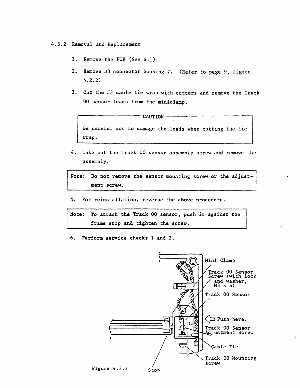
4.3.2
Removal and Replacement
1.
2.
Remove
Remove
the
PWB
J3
connector
(See
4.2.2)
3.
Cut
the
J3
00
sensor
cable
leads
tie
from
4.1).
housing
wrap
the
miniclamp•
7.
with
(Refer
cutters
to
page
9,
and remove
figure
the
Track
...----------
Be
wrap.
4.
Take
assembly.
Note:
5.
For
Note:
6.
Perform
careful
out
Do
not
ment
not
the
remove
screw.
reinstallation,
To
attach
frame
stop
service
to
Track
the
and
checks
CAUTION
damage
00
the
reverse
Track
tighten
the
sensor
sensor
00
1 and
--------------,
leads
when
assembly
mounting screw
the
above
sensor,
the
push
screw.
2.
cutting
the
screw and remove
or
the
adjust-
procedure.
it
against
the
tie
the
Figure
4.3.1
Stop
Track
Screw
I and
""
Track 00 Mounting
M3
able
00
(with
washer,
x
6)
00
Sensor
Tie
screw
Sensor
lock

4.4
Write
Protect
Sensor
(See
Chapter
5,
Figure
3)
4.4.1
Service
1.
Power up
2.
Check
a.
b.
3.
Check
withawrite
in
a.
Check
the
drive.
the
following
Write
The
between
Write
The
Protect
voltage
1.0
Protect
voltage.
between 0 and
the
following
protect
the
drive
Write
The
voltage
and
Protect
with
Lamp:
across
and
1.7
Sensor:
across
0.5
withawrite
seal
the
front
Sensor:
across
no
disk
J3-A8 and G
v.
J3-A9 and G
V.
over
J3-A9 and G
the
lever
in
the
(GND)
(GND)
protected
write
in
lock
(GND)
drive.
should
should
d~sk
protect
position.
should
be
be
(a
disk
notch)
be
4.4.2
between
Removal and
1.
Remove
2.
Remove
figure
3.
Remove
4.
5.
6.
Lift
Remove
Take
(two
the
locations)
out
and remove
2.5
and
Replac~ment
the
PWB
(See
housing
4 from
4.2.2).
the
carrier
tabs
from
and remove
the
In
Use
Lamp
the
screws
the
front
5.25
4.1).
the
cover
the
for
lever
V.
J3
connector.
screws and remove
carrier
the
the
front
and
and
write
leads.
lever,
carrier
(See page
the
protect
and
carrier
assembly.
9,
carrier
lead
cover.
clamps
assembly,
 Loading...