

Page 1

AC Servo Drives
-V Series
USER’S MANUAL
Design and Maintenance
Linear Motor
Command Option Attachable Type
SGDV SERVOPACK
SGLGW/SGLFW/SGLTW/SGLC/SGT Linear Servomotors
MANUAL NO. SIEP S800000 66H
Outline
Panel Display and
Operation of Digital Operator
Wiring and Connection
Operation
Adjustments
Utility Functions (Fn)
Monitor Displays (Un)
Troubleshooting
Appendix
1
2
3
4
5
6
7
8
9
Page 2

Copyright © 2009 YASKAWA ELECTRIC CORPORATION
All rights reserved. No part of this publication may be reproduced, stored in a retrieval system,
or transmitted, in any form, or by any means, mechanical, electronic, photocopying, recording,
or otherwise, without the prior written permission of Yaskawa. No patent liability is assumed
with respect to the use of the information contained herein. Moreover, because Yaskawa is constantly striving to improve its high-quality products, the information contained in this manual is
subject to change without notice. Every precaution has been taken in the preparation of this
manual. Nevertheless, Yaskawa assumes no responsibility for errors or omissions. Neither is
any liability assumed for damages resulting from the use of the information contained in this
publication.
Page 3

About this Manual
This manual describes information required for designing, testing, adjusting, and maintaining Σ-V Series
SERVOPACKs.
Keep this manual in a location where it can be accessed for reference whenever required. Manuals outlined on
the following page must also be used as required by the application.
Description of Technical Terms
The following table shows the meanings of terms used in this manual.
Te rm Meaning
Cursor Input position indicated by Digital Operator
Servomotor Σ-V S e r i es S G L GW, SG L F W, S GLTW, S G L C linear servomotor or SGT linear slider
SERVOPACK Σ-V Series SGDV servo amplifier of command option attachable type
Servo Drive A set including a servomotor and SERVOPACK (i.e., a servo amplifier)
Servo System
Servo ON Power to motor ON
Servo OFF Power to motor OFF
Base Block (BB)
Servo Lock
Main Circuit Cable
Zero-speed Stopping Stopping the servomotor by setting the speed reference to 0
Linear Scale Connection
Cables
A servo control system that includes the combination of a servo drive with a host controller and peripheral devices
Power supply to motor is turned OFF by shutting off the base current to the power
transistor in the current SERVOPACK.
A state in which the motor is stopped and is in position loop with a position reference
of 0.
Cables which connect to the main circuit terminals, including main circuit power supply cables, control power supply cables, servomotor main circuit cables, and others.
A set of cables including a cable for connecting serial converter unit, a cable for connecting linear scale, and a cable for connecting hall sensor
IMPORTANT Explanations
The following icon is displayed for explanations requiring special attention.
• Indicates important information that should be memorized, as well as precautions, such as
alarm displays, that do not involve potential damage to equipment.
iii
Page 4

Parameter Meaning When Enabled Classification
Pn002
After restart
n.0
[Factory setting]
n.1
Uses the absolute linear scale as
an incremental linear scale.
Uses the absolute linear scale as
an absolute linear scale.
Setup
Parameter
number
Position
Force
Control methods for which the parameter applies.
Speed
: Speed control
: Position control
: Force control
Indicates the
parameter setting
before shipment.
Indicates when a
change to the
parameter will be
effective.
Indicates the
parameter
classification.
Indicates the
minimum setting unit
for the parameter.
Indicates the setting
range for the parameter.
The notation “n.” indicates a parameter
for selecting functions. Each corresponds to
the setting value of that digit. The notation shown
here means that the third digit is 1.
This section explains the
selections for the function.
Pn311
Vibration Detection Sensitivity
Classification
Setting Range Setting Unit Factory Setting When Enabled
50 to 500 1%
100 Immediately Tuning
Speed
Position
Force
Parameter
number
• Parameters for Selecting Functions
1st digit
2nd digit
3rd digit
4th digit
Digital Operator Display
(Display Example for Pn002)
Digit Notation Setting Notation
Meaning Notation Meaning
Pn002.0
Pn002.1
Pn002.2
Pn002.3
Indicates the value for the
1st digit of parameter Pn002.
Indicates the value for the
2nd digit of parameter Pn002.
Indicates the value for the
3rd digit of parameter Pn002.
Indicates the value for the
4th digit of parameter Pn002.
Pn002.0 = x
or n.x
Pn002.1 = x
or n.x
Indicates that the value for the
1st digit of parameter Pn002 is x.
Indicates that the value for the
2nd digit of parameter Pn002 is x.
Pn002.2 = x
or n.x
Pn002.3 = x
or n.x
Indicates that the value for the
3rd digit of parameter Pn002 is x.
Indicates that the value for the
4th digit of parameter Pn002 is x.
Notation
Notation Used in this Manual
• Notation for Reverse Signals
The names of reverse signals (i.e., ones that are valid when low) are written with a forward slash (/) before the
signal name.
Notation Example
BK
= /BK
• Notation for Parameters
The notation depends on whether the parameter requires a value setting (parameter for numeric settings) or
requires the selection of a function (parameter for selecting functions).
• Parameters for Numeric Settings
iv
Notation Example
Page 5

Manuals Related to the Σ-V Series
Refer to the following manuals as required.
Name
Σ-V Series
User’s Manual
Setup
Linear Motor
(No.: SIEP S800000 44)
Σ-V Series
Product Catalog
(No.: KAEP S800000 42)
Σ-V Series
User's Manual
Design and Maintenance
Linear Motor/
Command Option
Attachable Type
(this manual)
Σ-V Series/Σ-V Series
for Large-Capacity Models
User’s Manual
INDEXER Module
(No.: SIEP C720829 02)
Σ-V Series/Σ-V Series
for Large-Capacity Models
User’s Manual
DeviceNet Module
(No.: SIEP C720829 07)
Σ-V Series
User’s Manual
Operation of Digital Operator
(No.: SIEP S800000 55)
Σ-V Series
AC SERVOPACK SGDV
Safety Precautions
(No.: TOBP C710800 10)
Σ Series
Digital Operator
Safety Precautions
(No.: TOBP C730800 00)
AC SERVOMOTOR
Safety Precautions
(No.: TOBP C230200 00)
Selecting
Models and
Peripheral
Ratings and
Specifications
System
Design
Panels and
Wiring
Trial
Operation
Devices
−−− −−
−−−−
−− −
− −
− −
−−−−
−− −−
−−−−−−
−−− −−
Trial
Operation
and Servo
Adjustment
Maintenance
and
Inspection
v
Page 6
WARNING
CAUTION
PROHIBITED
MANDATORY
Safety Information
The following conventions are used to indicate precautions in this manual. Failure to heed precautions provided in this manual can result in serious or possibly even fatal injury or damage to the products or to related
equipment and systems.
Indicates precautions that, if not heeded, could possibly result in loss of
life or serious injury.
Indicates precautions that, if not heeded, could result in relatively serious
or minor injury, damage to the product, or faulty operation.
In some situations, the precautions indicated could have serious
consequences if not heeded.
Indicates prohibited actions that must not be performed. For example,
this symbol would be used to indicate that fire is prohibited as follows:
Indicates compulsory actions that must be performed. For example, this
symbol would be used to indicate that grounding is compulsory as
follows:
vi
Page 7
Safety Precautions
This section describes important precautions that must be followed during storage, transportation, installation,
wiring, operation, maintenance, inspection, and disposal. Be sure to always observe these precautions thoroughly.
• If you have a pacemaker or any other electronic medical device, do not go near the magnetic way of
the servomotor.
Failure to observe this warning may result in the malfunction of the medical device.
• Be sure to use nonmagnetic tools when installing or working close to the servomotor.
(Example: a beryllium-copper alloy hexagonal wrench set, made by NGK Insulators, Ltd.)
• Never touch the servomotor or machinery during operation.
Failure to observe this warning may result in injury.
• Before starting operation with a machine connected, make sure that an emergency stop can be
applied at any time.
Failure to observe this warning may result in injury or damage to the equipment.
• Before wiring, install the SERVOPACK and the servomotor.
Failure to observe this warning may result in electric shock.
• Never touch the inside of the SERVOPACKs.
Failure to observe this warning may result in electric shock.
• Do not remove the cover of the power supply terminal block while the power is ON.
Failure to observe this warning may result in electric shock.
• Do not touch the power supply terminals while the CHARGE lamp is ON after turning power OFF
because high voltage may still remain in the SERVOPACK. Make sure the CHARGE lamp is OFF
first before starting to do wiring or inspections.
Residual voltage may cause electric shock.
• Follow the procedures and instructions provided in the manuals for the products being used in the
trial operation.
Failure to do so may result not only in faulty operation and damage to equipment, but also in personal injury.
• Do not remove the top front cover, cables, connectors, or optional items from the SERVOPACK
while the power is ON.
Failure to observe this warning may result in electric shock or equipment damage.
• Do not damage, pull, exert excessive force on, or place heavy objects on the cables.
Failure to observe this warning may result in electric shock, stopping operation of the product, or fire.
• Do not modify the product.
Failure to observe this warning may result in injury, damage to the equipment, or fire.
• Provide appropriate braking devices on the machine side to ensure safety.
Failure to observe this warning may result in injury.
• Do not come close to the machine immediately after resetting an instantaneous power interruption
to avoid an unexpected restart. Take appropriate measures to ensure safety against an unexpected
restart.
Failure to observe this warning may result in injury.
• Connect the ground terminal according to local electrical codes (100 Ω or less for a SERVOPACK
with a 100 V, 200 V power supply, 10 Ω or less for a SERVOPACK with a 400 V power supply).
Improper grounding may result in electric shock or fire.
WARNING
• Installation, disassembly, or repair must be performed only by authorized personnel.
Failure to observe this warning may result in electric shock or injury.
• The person who designs a system using the safety function (Hard Wire Baseblock function) must
have full knowledge of the related safety standards and full understanding of the instructions in this
manual.
Failure to observe this warning may result in injury or damage to the equipment.
vii
Page 8

Storage and Transportation
CAUTION
• Be sure to store the magnetic way in the package that was used for delivery.
• Do not store or install the product in the following locations.
Failure to observe this caution may result in fire, electric shock, or damage to the equipment.
• Locations subject to direct sunlight
• Locations subject to temperatures outside the range specified in the storage/installation temperature conditions
• Locations subject to humidity outside the range specified in the storage/installation humidity conditions
• Locations subject to condensation as the result of extreme changes in temperature
• Locations subject to corrosive or flammable gases
• Locations subject to dust, salts, or iron dust
• Locations subject to exposure to water, oil, or chemicals
• Locations subject to shock or vibration
• Do not hold the servomotor by the cables while transporting it.
Failure to observe this caution may result in injury or malfunction.
• Do not place any load exceeding the limit specified on the packing box.
Failure to observe this caution may result in injury or malfunction.
• If disinfectants or insecticides must be used to treat packing materials such as wooden frames, pallets, or plywood, the packing materials must be treated before the product is packaged, and methods other than fumigation must be used.
Example: Heat treatment, where materials are kiln-dried to a core temperature of 56
minutes or more.
If the electronic products, which include stand-alone products and products installed in machines, are packed
with fumigated wooden materials, the electrical components may be greatly damaged by the gases or fumes
resulting from the fumigation process. In particular, disinfectants containing halogen, which includes chlorine, fluorine, bromine, or iodine can contribute to the erosion of the capacitors.
°
C for 30
viii
Page 9

Installation
Cover
Magnetic way
• When unpacking and installing magnetic way, check that no metal fragments or magnetized objects
near the magnetic because they may be affected by the magnetic attraction of the magnetic way.
Failure to observe this caution may result in injury or damage to the magnetic way's magnets.
• Do not use the magnetic way near metal or other magnetized objects.
Failure to observe this caution may result in injury.
• Do not place clocks, magnetic cards, floppy disks, or measuring instruments close to the magnetic
way.
Failure to observe this caution may result in malfunction or damage to these items by the magnetic force.
• Securely mount the servomotor onto the machine.
If the servomotor is not mounted securely, it may loosen during operation.
• Do not carry the magnetic way by its magnet protection cover.
Failure to observe this caution may result in injury by the cover’s edge or the shape of the cover may become
distorted.
CAUTION
• When removing the dummy plate for reducing magnetic force used for the SGLFW magnetic way,
pay attention to the magnetic attraction of the magnetic way. Do not place the removed plate close
to the magnetic way.
Failure to observe this caution may result in injury or damage to the magnetic way’s magnets or the magnet
protection cover.
• Install SERVOPACKs, servomotors, and regenerative resistors on nonflammable objects.
Installation directly onto or near flammable objects may result in fire.
• Never use the product in an environment subject to water, corrosive gases, flammable gases, or
combustibles.
Failure to observe this caution may result in electric shock or fire.
• Do not step on or place a heavy object on the product.
Failure to observe this caution may result in injury or malfunction.
• Do not cover the inlet or outlet ports and prevent any foreign objects from entering the product.
Failure to observe this caution may cause internal elements to deteriorate resulting in malfunction or fire.
• Be sure to install the product in the correct direction.
Failure to observe this caution may result in malfunction.
• Provide the specified clearances between the SERVOPACK and the control panel or with other
devices.
Failure to observe this caution may result in fire or malfunction.
• Do not apply any strong impact.
Failure to observe this caution may result in malfunction.
ix
Page 10

Wiring
CAUTION
• Be sure to wire correctly and securely.
Failure to observe this caution may result in motor overrun, injury, or malfunction.
• Securely tighten the cable connector screws and securing mechanism.
If the connector screws and securing mechanism are not secure, they may loosen during operation.
• Use cables with a radius, heat resistance, and flexibility suitable for the system.
• If the SERVOPACK malfunctions, turn OFF the main circuit’s power supply of the SERVOPACK.
The continuous flow of a large current may cause fire.
• Use a noise filter to minimize the effects of electromagnetic damage.
Failure to observe this caution may result in electromagnetic damage to electronic devices used near the SERVOPACK.
• Do not connect a commercial power supply to the U, V, or W terminals for the servomotor connection.
Failure to observe this caution may result in injury or fire.
• Securely connect the main circuit terminals.
Failure to observe this caution may result in fire.
• Do not bundle or run the main circuit cables together with the I/O signal cables or the linear scale
connection cables in the same duct. Keep the main circuit cables separated from the I/O signal
cables and the linear scale connection cables with a gap of at least 30 cm.
Placing these cables too close to each other may result in malfunction.
• Use shielded twisted-pair cables or screened unshielded twisted-pair cables for I/O signal cables
and the linear scale connection cables.
• Make sure that the length of each cable is equal to or shorter than the maximum wiring length listed
here.
• I/O signal cables: 3 m
• Connection cables for linear servomotor main circuit: 20 m
• Connection cables for serial converter unit: 20 m
• Connection cables for linear scale: 15 m
• Connection cables for hall sensor: 15 m
• Control power supply cables for the SERVOPACK with a 400-V power supply (+24 V, 0 V):10 m
• Be sure to observe the following precautions when wiring the SERVOPACK main circuit terminal
blocks.
• Do not turn the SERVOPACK power ON until all wiring, including the main circuit terminal blocks, has
been completed.
• If a connector is used for the main circuit terminals, remove the connector from the SERVOPACK before
you wire it.
• Insert only one wire into one opening in the main circuit connector.
• Make sure that no part of the core wire comes into contact with (i.e., short-circuits) adjacent wires.
• Do not connect the SERVOPACK for 200 V directly to a voltage of 400 V.
The SERVOPACK will be destroyed.
• When connecting an External Regenerative Resistor to the SGDV-3R8A, -5R5A, -7R6A, -120A,
-180A, -200A, -330A, -1R9D, -3R5D, -5R4D, -8R4D, -120D, or -170D, first remove the lead wire
between the B2 and B3 terminals on the SERVOPACK, and then connect the External Regenerative Resistor.
There is a risk of SERVOPACK failure.
• Always use the specified power supply voltage.
An incorrect voltage may result in fire or malfunction.
• Make sure that the polarity is correct.
Incorrect polarity may cause ruptures or damage.
• Take appropriate measures to ensure that the input power supply is supplied within the specified
voltage fluctuation range. Be particularly careful in places where the power supply is unstable.
An incorrect power supply may result in damage to the equipment.
• Install external breakers or other safety devices against short-circuiting in external wiring.
Failure to observe this caution may result in fire.
• Take appropriate and sufficient countermeasures for each form of potential interference when
installing systems in the following locations.
• Locations subject to static electricity or other forms of noise
• Locations subject to strong electromagnetic fields and magnetic fields
• Locations subject to possible exposure to radioactivity
• Locations close to power supplies
Failure to observe this caution may result in damage to the equipment.
• Wiring or inspection must be performed by a technical expert.
•
Use a
24-VDC power supply with double insulation or reinforced insulation.
x
Page 11

Operation
• Do not stand within the machine's range of motion during operation.
Failure to observe this caution may result in injury.
• Always use the servomotor and SERVOPACK in one of the specified combinations.
Failure to observe this caution may result in fire or malfunction.
• Before operation, install limit switches or stoppers at the ends of the range of movement to prevent
unexpected accidents.
Failure to observe this caution may result in injury.
• During trial operation, confirm that the holding brake works correctly. Furthermore, secure system
safety against problems such as signal line disconnection.
Failure to observe this caution may result in injury or equipment damage.
• Before starting operation with a machine connected, change the parameter settings to match the
parameters of the machine.
Starting operation without matching the proper settings may cause the machine to run out of control or malfunction.
• Do not turn the power ON and OFF more than necessary.
Do not use the SERVOPACK for applications that require the power to turn ON and OFF frequently. Such
applications will cause elements in the SERVOPACK to deteriorate.
As a guideline, at least one hour should be allowed between the power being turned ON and OFF once actual
operation has been started.
• When carrying out JOG operation (Fn002), origin search (Fn003), or EasyFFT (Fn206), forcing
movable machine parts to stop does not work for forward overtravel or reverse overtravel. Take
necessary precautions.
Failure to observe this caution may result in damage to the equipment.
• When using the servomotor for a vertical axis, install safety devices to prevent workpieces from falling due to alarms or overtravels. Set the servomotor so that it will stop in the zero clamp state when
overtravel occurs.
Failure to observe this caution may cause workpieces to fall due to overtravel.
• When not using the turning-less function, set the correct mass ratio (Pn103).
Setting an incorrect mass ratio may cause machine vibration.
• Do not touch the SERVOPACK heat sinks, regenerative resistor, or servomotor while power is ON
or soon after the power is turned OFF.
Failure to observe this caution may result in burns due to high temperatures.
• Do not make any extreme adjustments or setting changes of parameters.
Failure to observe this caution may result in injury or damage to the equipment due to unstable operation.
• If an alarm occurs, shut down the main circuit power supply.
Failure to observe this caution may result in fire due to regenerative resistor overheating caused by regenerative transistor failure.
• When an alarm occurs, remove the cause, reset the alarm after confirming safety, and then resume
operation.
Failure to observe this caution may result in damage to the equipment, fire, or injury.
• An alarm or warning may occur if communications are performed with the host controller while the
SigmaWin+ or Digital Operator is operating.
If an alarm or warning occurs, it may stop the current process and stop the system.
CAUTION
Maintenance and Inspection
• Do not disassemble the SERVOPACK and the servomotor.
Failure to observe this caution may result in electric shock or injury.
• Do not attempt to change wiring while the power is ON.
Failure to observe this caution may result in electric shock or injury.
• When replacing the SERVOPACK, resume operation only after copying the previous SERVOPACK
parameters to the new SERVOPACK.
Failure to observe this caution may result in damage to the equipment.
CAUTION
xi
Page 12

Disposal Precautions
CAUTION
• Correctly discard the product as stipulated by regional, local, and municipal laws and regulations. Be sure to include these contents in all labelling and warning notifications on the
final product as necessary.
General Precautions
Observe the following general precautions
to ensure safe application.
• The products shown in illustrations in this manual are sometimes shown without covers or protective guards.
Always replace the cover or protective guard as specified first, and then operate the products in accordance with
the manual.
• The drawings presented in this manual are typical examples and may not match the product you received.
• If the manual must be ordered due to loss or damage, inform your nearest Yaskawa representative or one of the
offices listed on the back of this manual.
xii
Page 13

Warranty
(1) Details of Warranty
Warranty Period
Warranty Scope
(2) Limitations of Liability
The warranty period for a product that was purchased (hereinafter called “delivered product”) is one year from
the time of delivery to the location specified by the customer or 18 months from the time of shipment from the
Yaskawa factory, whichever is sooner.
Yaskawa shall replace or repair a defective product free of charge if a defect attributable to Yaskawa occurs
during the warranty period above. This warranty does not cover defects caused by the delivered product reaching the end of its service life and replacement of parts that require replacement or that have a limited service
life.
This warranty does not cover failures that result from any of the following causes.
1. Improper handling, abuse, or use in unsuitable conditions or in environments not described in product catalogs or manuals, or in any separately agreed-upon specifications
2. Causes not attributable to the delivered product itself
3. Modifications or repairs not performed by Yaskawa
4. Abuse of the delivered product in a manner in which it was not originally intended
5. Causes that were not foreseeable with the scientific and technological understanding at the time of shipment from Yaskawa
6. Events for which Yaskawa is not responsible, such as natural or human-made disasters
1. Yaskawa shall in no event be responsible for any damage or loss of opportunity to the customer that arises
due to failure of the delivered product.
2. Yaskawa shall not be responsible for any programs (including parameter settings) or the results of program
execution of the programs provided by the user or by a third party for use with programmable Yaskawa
products.
3. The information described in product catalogs or manuals is provided for the purpose of the customer purchasing the appropriate product for the intended application. The use thereof does not guarantee that there
are no infringements of intellectual property rights or other proprietary rights of Yaskawa or third parties,
nor does it construe a license.
4. Yaskawa shall not be responsible for any damage arising from infringements of intellectual property rights
or other proprietary rights of third parties as a result of using the information described in catalogs or manuals.
xiii
Page 14

(3) Suitability for Use
1. It is the customer’s responsibility to confirm conformity with any standards, codes, or regulations that
apply if the Yaskawa product is used in combination with any other products.
2. The customer must confirm that the Yaskawa product is suitable for the systems, machines, and equipment
used by the customer.
3. Consult with Yaskawa to determine whether use in the following applications is acceptable. If use in the
application is acceptable, use the product with extra allowance in ratings and specifications, and provide
safety measures to minimize hazards in the event of failure.
• Outdoor use, use involving potential chemical contamination or electrical interference, or use in conditions or environments not described in product catalogs or manuals
• Nuclear energy control systems, combustion systems, railroad systems, aviation systems, vehicle systems, medical equipment, amusement machines, and installations subject to separate industry or government regulations
• Systems, machines, and equipment that may present a risk to life or property
• Systems that require a high degree of reliability, such as systems that supply gas, water, or electricity, or
systems that operate continuously 24 hours a day
• Other systems that require a similar high degree of safety
4. Never use the product for an application involving serious risk to life or property without first ensuring that
the system is designed to secure the required level of safety with risk warnings and redundancy, and that the
Yaskawa product is properly rated and installed.
5. The circuit examples and other application examples described in product catalogs and manuals are for reference. Check the functionality and safety of the actual devices and equipment to be used before using the
product.
6. Read and understand all use prohibitions and precautions, and operate the Yaskawa product correctly to
prevent accidental harm to third parties.
(4) Specifications Change
The names, specifications, appearance, and accessories of products in product catalogs and manuals may be
changed at any time based on improvements and other reasons. The next editions of the revised catalogs or
manuals will be published with updated code numbers. Consult with your Yaskawa representative to confirm
the actual specifications before purchasing a product.
xiv
Page 15

Harmonized Standards
North American Safety Standards (UL)
Model
SERVOPACK SGDV UL508C (E147823)
EU Directives
Model EU Directives Harmonized Standards
Machinery Directive
2006/42/EC
EMC Directive
SERVOPACK SGDV
2014/30/EU
Low Voltage Directive
2014/35/EU
RoHS Directive
2011/65/EU
Safety Standards
UL Standards
(UL File No.)
EN ISO13849-1: 2015
EN 55011 group1 classA
EN 61000-6-2
EN 61000-6-4
EN 61800-3 (Category C2, Second Environment)
EN 50178
EN 61800-5-1
EN 50581
Model Safety Standards Standards
EN ISO13849-1: 2015
IEC 60204-1
IEC 61508 series
IEC 62061
IEC 61800-5-2
SERVOPACK SGDV
Safety of Machinery
Functional Safety
EMC IEC 61326-3-1
• Safety Performance
Items Standards Performance Level
Safety Integrity Level
Probability of Dangerous Failure per Hour
Performance Level EN ISO 13849-1 PL d (Category 3)
IEC 61508 SIL2
IEC 62061 SILCL2
IEC 61508
IEC 62061
PFH = 1.7 × 10
(0.17% of SIL2)
-9
[1/h]
xv
Page 16

(cont’d)
Items Standards Performance Level
Mean Time to Dangerous Failure of Each
Channel
Average Diagnostic Coverage EN ISO 13849-1 DCavg: Low
Stop Category IEC 60204-1 Stop category 0
Safety Function IEC 61800-5-2 STO
Proof test Interval IEC 61508 10 years
EN ISO 13849-1 MTTFd: High
xvi
Page 17

Contents
Chapter 1 Outline . . . . . . . . . . . . . . . . . . . . . . . . . . . . . . . . . . . . . . . . . . . .1-1
1.1 Σ-V Series SERVOPACKs . . . . . . . . . . . . . . . . . . . . . . . . . . . . . . . . . . . . . . . 1-2
1.2 SERVOPACKs . . . . . . . . . . . . . . . . . . . . . . . . . . . . . . . . . . . . . . . . . . . . . . . . 1-2
1.3 Part Names . . . . . . . . . . . . . . . . . . . . . . . . . . . . . . . . . . . . . . . . . . . . . . . . . . 1-2
1.4 SERVOPACK Ratings and Specifications . . . . . . . . . . . . . . . . . . . . . . . . . . . 1-3
1.4.1 Ratings . . . . . . . . . . . . . . . . . . . . . . . . . . . . . . . . . . . . . . . . . . . . . . . . . . . . . . . . . . . . . . . . 1-3
1.4.2 Basic Specifications . . . . . . . . . . . . . . . . . . . . . . . . . . . . . . . . . . . . . . . . . . . . . . . . . . . . . .1-4
1.5 SERVOPACK Internal Block Diagrams . . . . . . . . . . . . . . . . . . . . . . . . . . . . . 1-7
1.5.1 Single-phase 100 V, SGDV-R70FE5A, -R90FE5A, -2R1FE5A Models . . . . . . . . . . . . . . . 1-7
1.5.2 Single-phase 100 V, SGDV-2R8FE5A Model. . . . . . . . . . . . . . . . . . . . . . . . . . . . . . . . . . . 1-8
1.5.3 Three-phase 200 V, SGDV-R70AE5A, -R90AE5A, -1R6AE5A Models . . . . . . . . . . . . . . .1-8
1.5.4 Three-phase 200 V, SGDV-2R8AE5A Model. . . . . . . . . . . . . . . . . . . . . . . . . . . . . . . . . . .1-9
1.5.5 Three-phase 200 V, SGDV-3R8AE5A, -5R5AE5A, -7R6AE5A Models . . . . . . . . . . . . . . .1-9
1.5.6 Three-phase 200 V, SGDV-120AE5A Model . . . . . . . . . . . . . . . . . . . . . . . . . . . . . . . . . . 1-10
1.5.7 Three-phase 200 V, SGDV-180AE5A, -200AE5A Models . . . . . . . . . . . . . . . . . . . . . . . .1-10
1.5.8 Three-phase 200 V, SGDV-330AE5A Model . . . . . . . . . . . . . . . . . . . . . . . . . . . . . . . . . . 1-11
1.5.9 Three-phase 200 V, SGDV-550AE5A Models . . . . . . . . . . . . . . . . . . . . . . . . . . . . . . . . . 1-11
1.5.10 Three-phase 400 V, SGDV-1R9DE5A, -3R5DE5A, -5R4DE5A Models. . . . . . . . . . . . . 1-12
1.5.11 Three-phase 400 V, SGDV-8R4DE5A, -120DE5A Models. . . . . . . . . . . . . . . . . . . . . . .1-12
1.5.12 Three-phase 400 V, SGDV-170DE5A Model . . . . . . . . . . . . . . . . . . . . . . . . . . . . . . . . .1-13
1.5.13 Three-phase 400 V, SGDV-260DE5A Model . . . . . . . . . . . . . . . . . . . . . . . . . . . . . . . . .1-13
1.6 Examples of Servo System Configurations . . . . . . . . . . . . . . . . . . . . . . . . . 1-14
1.6.1 Connecting to SGDV-FE5A SERVOPACK . . . . . . . . . . . . . . . . . . . . . . . . . . . . . . .1-14
1.6.2 Connecting to SGDV-AE5A SERVOPACK . . . . . . . . . . . . . . . . . . . . . . . . . . . . . . .1-15
1.6.3 Connecting to SGDV-DE5A SERVOPACK . . . . . . . . . . . . . . . . . . . . . . . . . . . . . . . 1-17
1.7 SERVOPACK Model Designation . . . . . . . . . . . . . . . . . . . . . . . . . . . . . . . . 1-18
1.8 Servo Drive Maintenance and Inspection . . . . . . . . . . . . . . . . . . . . . . . . . . 1-19
1.8.1 SERVOPACK Inspection . . . . . . . . . . . . . . . . . . . . . . . . . . . . . . . . . . . . . . . . . . . . . . . . .1-19
1.8.2 SERVOPACK’s Parts Replacement Schedule . . . . . . . . . . . . . . . . . . . . . . . . . . . . . . . . .1-19
1.8.3 Servomotor Inspection . . . . . . . . . . . . . . . . . . . . . . . . . . . . . . . . . . . . . . . . . . . . . . . . . . .1-20
About this Manual . . . . . . . . . . . . . . . . . . . . . . . . . . . . . . . . . . . . . . . . . . . . . . . . . . . . . . . . iii
Safety Precautions. . . . . . . . . . . . . . . . . . . . . . . . . . . . . . . . . . . . . . . . . . . . . . . . . . . . . . . vii
Warranty. . . . . . . . . . . . . . . . . . . . . . . . . . . . . . . . . . . . . . . . . . . . . . . . . . . . . . . . . . . . . . . xiii
Harmonized Standards . . . . . . . . . . . . . . . . . . . . . . . . . . . . . . . . . . . . . . . . . . . . . . . . . . . xv
Chapter 2 Panel Display and Operation of Digital Operator . . . . . . . . . . . .2-1
2.1 Panel Display . . . . . . . . . . . . . . . . . . . . . . . . . . . . . . . . . . . . . . . . . . . . . . . . . 2-2
2.1.1 Status Display . . . . . . . . . . . . . . . . . . . . . . . . . . . . . . . . . . . . . . . . . . . . . . . . . . . . . . . . . . 2-2
2.1.2 Alarm and Warning Display . . . . . . . . . . . . . . . . . . . . . . . . . . . . . . . . . . . . . . . . . . . . . . . .2-2
2.1.3 Hard Wire Base Block Display . . . . . . . . . . . . . . . . . . . . . . . . . . . . . . . . . . . . . . . . . . . . . .2-2
2.1.4 Overtravel Display . . . . . . . . . . . . . . . . . . . . . . . . . . . . . . . . . . . . . . . . . . . . . . . . . . . . . . . 2-2
2.2 Operation of Digital Operator . . . . . . . . . . . . . . . . . . . . . . . . . . . . . . . . . . . . . 2-3
2.3 Utility Functions (Fn) . . . . . . . . . . . . . . . . . . . . . . . . . . . . . . . . . . . . . . 2-3
2.4 Parameters (Pn) . . . . . . . . . . . . . . . . . . . . . . . . . . . . . . . . . . . . . . . . . . 2-4
2.4.1 Parameter Classification . . . . . . . . . . . . . . . . . . . . . . . . . . . . . . . . . . . . . . . . . . . . . . . . . .2-4
2.4.2 Notation for Parameters. . . . . . . . . . . . . . . . . . . . . . . . . . . . . . . . . . . . . . . . . . . . . . . . . . .2-4
2.4.3 Setting Parameters . . . . . . . . . . . . . . . . . . . . . . . . . . . . . . . . . . . . . . . . . . . . . . . . . . . . . .2-5
2.5 Monitor Displays (Un). . . . . . . . . . . . . . . . . . . . . . . . . . . . . . . . . . . . . . 2-7
xvii
Page 18

Chapter 3 Wiring and Connection . . . . . . . . . . . . . . . . . . . . . . . . . . . . . . . .3-1
3.1 Main Circuit Wiring . . . . . . . . . . . . . . . . . . . . . . . . . . . . . . . . . . . . . . . . . . . . . 3-2
3.1.1 Main Circuit Terminals . . . . . . . . . . . . . . . . . . . . . . . . . . . . . . . . . . . . . . . . . . . . . . . . . . . .3-2
3.1.2 Using a Standard Power Supply
(Single-phase 100 V, Three-phase 200 V, or Three-phase 400 V) . . . . . . . . . . . . . . . . . . 3-3
3.1.3 Using the SERVOPACK with Single-phase, 200 V Power Input . . . . . . . . . . . . . . . . . . . 3-11
3.1.4 Using the SERVOPACK with a DC Power Input . . . . . . . . . . . . . . . . . . . . . . . . . . . . . . . 3-14
3.1.5 Using More Than One SERVOPACK. . . . . . . . . . . . . . . . . . . . . . . . . . . . . . . . . . . . . . . . 3-18
3.1.6 General Precautions for Wiring . . . . . . . . . . . . . . . . . . . . . . . . . . . . . . . . . . . . . . . . . . . . 3-19
3.2 I/O Signal Connections. . . . . . . . . . . . . . . . . . . . . . . . . . . . . . . . . . . . . . . . . 3-20
3.2.1 I/O Signal (CN1) Names and Functions. . . . . . . . . . . . . . . . . . . . . . . . . . . . . . . . . . . . . .3-20
3.2.2 Safety Function Signal (CN8) Names and Functions. . . . . . . . . . . . . . . . . . . . . . . . . . . .3-21
3.2.3 Example of I/O Signal Connections . . . . . . . . . . . . . . . . . . . . . . . . . . . . . . . . . . . . . . . . . 3-22
3.3 I/O Signal Allocations . . . . . . . . . . . . . . . . . . . . . . . . . . . . . . . . . . . . . . . . . . 3-23
3.3.1 Input Signal Allocations . . . . . . . . . . . . . . . . . . . . . . . . . . . . . . . . . . . . . . . . . . . . . . . . . . 3-23
3.3.2 Output Signal Allocations. . . . . . . . . . . . . . . . . . . . . . . . . . . . . . . . . . . . . . . . . . . . . . . . .3-25
3.4 Examples of Connection to Host Controller . . . . . . . . . . . . . . . . . . . . . . . . . 3-26
3.4.1 Sequence Input Circuit. . . . . . . . . . . . . . . . . . . . . . . . . . . . . . . . . . . . . . . . . . . . . . . . . . . 3-26
3.4.2 Sequence Output Circuit . . . . . . . . . . . . . . . . . . . . . . . . . . . . . . . . . . . . . . . . . . . . . . . . .3-27
3.5 Wiring Communications Using Command Option Modules . . . . . . . . . . . . . 3-29
3.6 Linear Scale Connection . . . . . . . . . . . . . . . . . . . . . . . . . . . . . . . . . . . . . . . 3-30
3.6.1 Linear Scale Signal (CN2) Names and Functions . . . . . . . . . . . . . . . . . . . . . . . . . . . . . . 3-30
3.6.2 Serial Converter Unit . . . . . . . . . . . . . . . . . . . . . . . . . . . . . . . . . . . . . . . . . . . . . . . . . . . . 3-30
3.6.3 Linear Scale Connection Examples . . . . . . . . . . . . . . . . . . . . . . . . . . . . . . . . . . . . . . . . . 3-33
3.7 Connecting Regenerative Resistors. . . . . . . . . . . . . . . . . . . . . . . . . . . . . . . 3-37
3.7.1 Connecting Regenerative Resistors. . . . . . . . . . . . . . . . . . . . . . . . . . . . . . . . . . . . . . . . . 3-37
3.7.2 Setting Regenerative Resistor Capacity . . . . . . . . . . . . . . . . . . . . . . . . . . . . . . . . . . . . .3-39
3.8 Noise Control and Measures for Harmonic Suppression . . . . . . . . . . . . . . . 3-40
3.8.1 Wiring for Noise Control. . . . . . . . . . . . . . . . . . . . . . . . . . . . . . . . . . . . . . . . . . . . . . . . . .3-40
3.8.2 Precautions on Connecting Noise Filter. . . . . . . . . . . . . . . . . . . . . . . . . . . . . . . . . . . . . . 3-42
3.8.3 Connecting a Reactor for Harmonic Suppression . . . . . . . . . . . . . . . . . . . . . . . . . . . . . . 3-43
Chapter 4 Operation . . . . . . . . . . . . . . . . . . . . . . . . . . . . . . . . . . . . . . . . . .4-1
4.1 Option Module Function Settings . . . . . . . . . . . . . . . . . . . . . . . . . . . . . . . . . . 4-3
4.2 Settings for Common Basic Functions . . . . . . . . . . . . . . . . . . . . . . . . . . . . . . 4-4
4.2.1 Inspection and Checking before Operation . . . . . . . . . . . . . . . . . . . . . . . . . . . . . . . . . . . . 4-4
4.2.2 Servomotor Movement Direction . . . . . . . . . . . . . . . . . . . . . . . . . . . . . . . . . . . . . . . . . . . .4-4
4.2.3 Overtravel. . . . . . . . . . . . . . . . . . . . . . . . . . . . . . . . . . . . . . . . . . . . . . . . . . . . . . . . . . . . . . 4-6
4.2.4 Electronic Gear . . . . . . . . . . . . . . . . . . . . . . . . . . . . . . . . . . . . . . . . . . . . . . . . . . . . . . . . .4-9
4.2.5 Encoder Output Pulses . . . . . . . . . . . . . . . . . . . . . . . . . . . . . . . . . . . . . . . . . . . . . . . . . .4-12
4.2.6 Setting Encoder Output Pulse . . . . . . . . . . . . . . . . . . . . . . . . . . . . . . . . . . . . . . . . . . . . .4-18
4.2.7 Holding Brakes. . . . . . . . . . . . . . . . . . . . . . . . . . . . . . . . . . . . . . . . . . . . . . . . . . . . . . . . .4-19
4.2.8 Stopping Servomotors after Servo OFF Command or Alarm Occurrence . . . . . . . . . . . . 4-23
4.2.9 Instantaneous Power Interruption Settings . . . . . . . . . . . . . . . . . . . . . . . . . . . . . . . . . . . 4-25
4.2.10 Motor Maximum Speed . . . . . . . . . . . . . . . . . . . . . . . . . . . . . . . . . . . . . . . . . . . . . . . . .4-26
4.2.11 SEMI F47 Function
(Force Limit Function for Low DC Power Supply Voltage for Main Circuit). . . . . . . . . . . 4-26
4.2.12 Setting Motor Overload Detection Level . . . . . . . . . . . . . . . . . . . . . . . . . . . . . . . . . . . . 4-29
4.3 Test Without Motor Function. . . . . . . . . . . . . . . . . . . . . . . . . . . . . . . . . . . . . 4-31
4.3.1 Motor Information. . . . . . . . . . . . . . . . . . . . . . . . . . . . . . . . . . . . . . . . . . . . . . . . . . . . . . .4-31
4.3.2 Motor Position and Speed Responses . . . . . . . . . . . . . . . . . . . . . . . . . . . . . . . . . . . . . . .4-32
4.3.3 Limitations . . . . . . . . . . . . . . . . . . . . . . . . . . . . . . . . . . . . . . . . . . . . . . . . . . . . . . . . . . . . 4-32
4.3.4 Digital Operator Displays during Testing without Motor . . . . . . . . . . . . . . . . . . . . . . . . . . 4-33
4.4 Limiting Force. . . . . . . . . . . . . . . . . . . . . . . . . . . . . . . . . . . . . . . . . . . . . . . . 4-34
4.4.1 Internal Force Limit . . . . . . . . . . . . . . . . . . . . . . . . . . . . . . . . . . . . . . . . . . . . . . . . . . . . . 4-34
4.4.2 External Force Limit . . . . . . . . . . . . . . . . . . . . . . . . . . . . . . . . . . . . . . . . . . . . . . . . . . . . . 4-35
4.4.3 Checking Output Force Limiting during Operation . . . . . . . . . . . . . . . . . . . . . . . . . . . . . . 4-36
xviii
Page 19

4.5 Absolute Linear Scales . . . . . . . . . . . . . . . . . . . . . . . . . . . . . . . . . . . . . . . . 4-37
4.5.1 Absolute Data Request (Sensor ON Command) . . . . . . . . . . . . . . . . . . . . . . . . . . . . . . .4-37
4.5.2 Absolute Data Reception Sequence . . . . . . . . . . . . . . . . . . . . . . . . . . . . . . . . . . . . . . . .4-38
4.6 Other Output Signals . . . . . . . . . . . . . . . . . . . . . . . . . . . . . . . . . . . . . . . . . . 4-41
4.6.1 Servo Alarm Output Signal (ALM) . . . . . . . . . . . . . . . . . . . . . . . . . . . . . . . . . . . . . . . . . .4-41
4.6.2 Warning Output Signal (/WARN) . . . . . . . . . . . . . . . . . . . . . . . . . . . . . . . . . . . . . . . . . . .4-41
4.6.3 Movement Detection Output Signal (/TGON). . . . . . . . . . . . . . . . . . . . . . . . . . . . . . . . . .4-42
4.6.4 Servo Ready Output Signal (/S-RDY) . . . . . . . . . . . . . . . . . . . . . . . . . . . . . . . . . . . . . . . 4-42
4.6.5 Speed Coincidence Output Signal (/V-CMP) . . . . . . . . . . . . . . . . . . . . . . . . . . . . . . . . . .4-43
4.6.6 Positioning Completed Output Signal (/COIN) . . . . . . . . . . . . . . . . . . . . . . . . . . . . . . . . .4-44
4.6.7 Positioning Near Output Signal (/NEAR) . . . . . . . . . . . . . . . . . . . . . . . . . . . . . . . . . . . . . 4-45
4.6.8 Speed Limit Detection Signal (/VLT) . . . . . . . . . . . . . . . . . . . . . . . . . . . . . . . . . . . . . . . . 4-46
4.7 Safety Function . . . . . . . . . . . . . . . . . . . . . . . . . . . . . . . . . . . . . . . . . . . . . . 4-48
4.7.1 Hard Wire Base Block (HWBB) Function . . . . . . . . . . . . . . . . . . . . . . . . . . . . . . . . . . . . .4-48
4.7.2 External Device Monitor (EDM1) . . . . . . . . . . . . . . . . . . . . . . . . . . . . . . . . . . . . . . . . . . . 4-53
4.7.3 Application Example of Safety Functions. . . . . . . . . . . . . . . . . . . . . . . . . . . . . . . . . . . . .4-55
4.7.4 Confirming Safety Functions . . . . . . . . . . . . . . . . . . . . . . . . . . . . . . . . . . . . . . . . . . . . . . 4-56
4.7.5 Safety Device Connections . . . . . . . . . . . . . . . . . . . . . . . . . . . . . . . . . . . . . . . . . . . . . . . 4-57
4.7.6 Precautions for Safety Functions . . . . . . . . . . . . . . . . . . . . . . . . . . . . . . . . . . . . . . . . . . . 4-58
Chapter 5 Adjustments . . . . . . . . . . . . . . . . . . . . . . . . . . . . . . . . . . . . . . . .5-1
5.1 Type of Adjustments and Basic Adjustment Procedure . . . . . . . . . . . . . . . . . 5-3
5.1.1 Adjustments . . . . . . . . . . . . . . . . . . . . . . . . . . . . . . . . . . . . . . . . . . . . . . . . . . . . . . . . . . . .5-3
5.1.2 Basic Adjustment Procedure . . . . . . . . . . . . . . . . . . . . . . . . . . . . . . . . . . . . . . . . . . . . . . .5-4
5.1.3 Monitoring Operation during Adjustment . . . . . . . . . . . . . . . . . . . . . . . . . . . . . . . . . . . . . .5-5
5.1.4 Safety Precautions on Adjustment of Servo Gains . . . . . . . . . . . . . . . . . . . . . . . . . . . . . . 5-8
5.2 Tuning-less Function . . . . . . . . . . . . . . . . . . . . . . . . . . . . . . . . . . . . . . . . . . 5-10
5.2.1 Tuning-less Function . . . . . . . . . . . . . . . . . . . . . . . . . . . . . . . . . . . . . . . . . . . . . . . . . . . .5-10
5.2.2 Tuning-less Levels Setting (Fn200) Procedure . . . . . . . . . . . . . . . . . . . . . . . . . . . . . . . .5-12
5.2.3 Related Parameters . . . . . . . . . . . . . . . . . . . . . . . . . . . . . . . . . . . . . . . . . . . . . . . . . . . . . 5-14
5.3 Advanced Autotuning (Fn201) . . . . . . . . . . . . . . . . . . . . . . . . . . . . . . . . . . . 5-15
5.3.1 Advanced Autotuning . . . . . . . . . . . . . . . . . . . . . . . . . . . . . . . . . . . . . . . . . . . . . . . . . . . .5-15
5.3.2 Advanced Autotuning Procedure . . . . . . . . . . . . . . . . . . . . . . . . . . . . . . . . . . . . . . . . . . 5-18
5.3.3 Related Parameters . . . . . . . . . . . . . . . . . . . . . . . . . . . . . . . . . . . . . . . . . . . . . . . . . . . . . 5-24
5.4 Advanced Autotuning by Reference (Fn202). . . . . . . . . . . . . . . . . . . . . . . . 5-25
5.4.1 Advanced Autotuning by Reference. . . . . . . . . . . . . . . . . . . . . . . . . . . . . . . . . . . . . . . . .5-25
5.4.2 Advanced Autotuning by Reference Procedure . . . . . . . . . . . . . . . . . . . . . . . . . . . . . . .5-27
5.4.3 Related Parameters . . . . . . . . . . . . . . . . . . . . . . . . . . . . . . . . . . . . . . . . . . . . . . . . . . . . . 5-31
5.5 One-parameter Tuning (Fn203) . . . . . . . . . . . . . . . . . . . . . . . . . . . . . . . . . . 5-32
5.5.1 One-parameter Tuning. . . . . . . . . . . . . . . . . . . . . . . . . . . . . . . . . . . . . . . . . . . . . . . . . . .5-32
5.5.2 One-parameter Tuning Procedure . . . . . . . . . . . . . . . . . . . . . . . . . . . . . . . . . . . . . . . . . .5-33
5.5.3 One-parameter Tuning Example . . . . . . . . . . . . . . . . . . . . . . . . . . . . . . . . . . . . . . . . . . .5-39
5.5.4 Related Parameters . . . . . . . . . . . . . . . . . . . . . . . . . . . . . . . . . . . . . . . . . . . . . . . . . . . . . 5-41
5.6 Anti-Resonance Control Adjustment Function (Fn204) . . . . . . . . . . . . . . . . 5-42
5.6.1 Anti-Resonance Control Adjustment Function . . . . . . . . . . . . . . . . . . . . . . . . . . . . . . . . . 5-42
5.6.2 Anti-Resonance Control Adjustment Function Operating Procedure . . . . . . . . . . . . . . . .5-43
5.6.3 Related Parameters . . . . . . . . . . . . . . . . . . . . . . . . . . . . . . . . . . . . . . . . . . . . . . . . . . . . . 5-47
5.7 Vibration Suppression Function (Fn205) . . . . . . . . . . . . . . . . . . . . . . . . . . . 5-48
5.7.1 Vibration Suppression Function . . . . . . . . . . . . . . . . . . . . . . . . . . . . . . . . . . . . . . . . . . . .5-48
5.7.2 Vibration Suppression Function Operating Procedure . . . . . . . . . . . . . . . . . . . . . . . . . . .5-49
5.7.3 Related Parameters . . . . . . . . . . . . . . . . . . . . . . . . . . . . . . . . . . . . . . . . . . . . . . . . . . . . . 5-52
5.8 Additional Adjustment Function . . . . . . . . . . . . . . . . . . . . . . . . . . . . . . . . . . 5-53
5.8.1 Switching Gain Settings . . . . . . . . . . . . . . . . . . . . . . . . . . . . . . . . . . . . . . . . . . . . . . . . . .5-53
5.8.2 Manual Adjustment of Friction Compensation . . . . . . . . . . . . . . . . . . . . . . . . . . . . . . . . .5-57
5.8.3 Current Control Mode Selection Function . . . . . . . . . . . . . . . . . . . . . . . . . . . . . . . . . . . . 5-59
5.8.4 Current Gain Level Setting. . . . . . . . . . . . . . . . . . . . . . . . . . . . . . . . . . . . . . . . . . . . . . . .5-59
5.8.5 Speed Detection Method Selection . . . . . . . . . . . . . . . . . . . . . . . . . . . . . . . . . . . . . . . . .5-59
xix
Page 20

5.9 Compatible Adjustment Function . . . . . . . . . . . . . . . . . . . . . . . . . . . . . . . . .5-60
5.9.1 Feedforward Reference . . . . . . . . . . . . . . . . . . . . . . . . . . . . . . . . . . . . . . . . . . . . . . . . . .5-60
5.9.2 Mode Switch (P/PI Switching) . . . . . . . . . . . . . . . . . . . . . . . . . . . . . . . . . . . . . . . . . . . . . 5-61
5.9.3 Force Reference Filter . . . . . . . . . . . . . . . . . . . . . . . . . . . . . . . . . . . . . . . . . . . . . . . . . . .5-63
5.9.4 Position Integral . . . . . . . . . . . . . . . . . . . . . . . . . . . . . . . . . . . . . . . . . . . . . . . . . . . . . . . . 5-65
Chapter 6 Utility Functions (Fn) . . . . . . . . . . . . . . . . . . . . . . . . . . . . .6-1
6.1 List of Utility Functions . . . . . . . . . . . . . . . . . . . . . . . . . . . . . . . . . . . . . . . . . .6-2
6.2 Alarm History Display (Fn000) . . . . . . . . . . . . . . . . . . . . . . . . . . . . . . . . . . . . 6-3
6.3 JOG Operation (Fn002) . . . . . . . . . . . . . . . . . . . . . . . . . . . . . . . . . . . . . . . . . 6-4
6.4 Origin Search (Fn003) . . . . . . . . . . . . . . . . . . . . . . . . . . . . . . . . . . . . . . . . . . 6-6
6.5 Program JOG Operation (Fn004). . . . . . . . . . . . . . . . . . . . . . . . . . . . . . . . . . 6-8
6.6 Initializing Parameter Settings (Fn005) . . . . . . . . . . . . . . . . . . . . . . . . . . . . 6-12
6.7 Clearing Alarm History (Fn006) . . . . . . . . . . . . . . . . . . . . . . . . . . . . . . . . . . 6-13
6.8 Offset Adjustment of Analog Monitor Output (Fn00C) . . . . . . . . . . . . . . . . . 6-14
6.9 Gain Adjustment of Analog Monitor Output (Fn00D) . . . . . . . . . . . . . . . . . . 6-16
6.10 Automatic Offset-Signal Adjustment of the Motor Current Detection
Signal (Fn00E) . . . . . . . . . . . . . . . . . . . . . . . . . . . . . . . . . . . . . . . . . . . . . . 6-18
6.11 Manual Offset-Signal Adjustment of the Motor Current Detection
Signal (Fn00F) . . . . . . . . . . . . . . . . . . . . . . . . . . . . . . . . . . . . . . . . . . . . . . 6-19
6.12 Write Prohibited Setting (Fn010) . . . . . . . . . . . . . . . . . . . . . . . . . . . . . . . . 6-21
6.13 Servomotor Model Display (Fn011) . . . . . . . . . . . . . . . . . . . . . . . . . . . . . . 6-23
6.14 Software Version Display (Fn012) . . . . . . . . . . . . . . . . . . . . . . . . . . . . . . . 6-24
6.15 Resetting Configuration Errors in Option Modules (Fn014) . . . . . . . . . . . . 6-25
6.16 Vibration Detection Level Initialization (Fn01B) . . . . . . . . . . . . . . . . . . . . . 6-26
6.17 Display of SERVOPACK and Servomotor ID (Fn01E) . . . . . . . . . . . . . . . . 6-28
6.18 Origin Setting (Fn020) . . . . . . . . . . . . . . . . . . . . . . . . . . . . . . . . . . . . . . . . 6-30
6.19 Software Reset (Fn030) . . . . . . . . . . . . . . . . . . . . . . . . . . . . . . . . . . . . . . . 6-31
6.20 Polarity Detection (Fn080) . . . . . . . . . . . . . . . . . . . . . . . . . . . . . . . . . . . . . 6-32
6.21 EasyFFT (Fn206) . . . . . . . . . . . . . . . . . . . . . . . . . . . . . . . . . . . . . . . . . . . .6-33
6.22 Online Vibration Monitor (Fn207) . . . . . . . . . . . . . . . . . . . . . . . . . . . . . . . . 6-36
xx
Chapter 7 Monitor Displays (Un) . . . . . . . . . . . . . . . . . . . . . . . . . . . .7-1
7.1 List of Monitor Displays . . . . . . . . . . . . . . . . . . . . . . . . . . . . . . . . . . . . . . . . . 7-2
7.2 Viewing Monitor Displays . . . . . . . . . . . . . . . . . . . . . . . . . . . . . . . . . . . . . . . . 7-3
7.3 Monitoring Input Signals. . . . . . . . . . . . . . . . . . . . . . . . . . . . . . . . . . . . . . . . . 7-4
7.3.1 Interpreting Input Signal Display Status . . . . . . . . . . . . . . . . . . . . . . . . . . . . . . . . . . . . . . .7-4
7.3.2 Input Signal Display Example . . . . . . . . . . . . . . . . . . . . . . . . . . . . . . . . . . . . . . . . . . . . . .7-5
7.4 Monitoring Output Signals . . . . . . . . . . . . . . . . . . . . . . . . . . . . . . . . . . . . . . . 7-6
7.4.1 Interpreting Output Signal Display Status . . . . . . . . . . . . . . . . . . . . . . . . . . . . . . . . . . . . .7-6
7.4.2 Output Signal Display Example . . . . . . . . . . . . . . . . . . . . . . . . . . . . . . . . . . . . . . . . . . . . .7-6
7.5 Monitoring Safety Input Signals . . . . . . . . . . . . . . . . . . . . . . . . . . . . . . . . . . . 7-7
7.5.1 Interpreting Safety Input Signal Display Status . . . . . . . . . . . . . . . . . . . . . . . . . . . . . . . . . 7-7
7.5.2 Safety Input Signal Display Example . . . . . . . . . . . . . . . . . . . . . . . . . . . . . . . . . . . . . . . . . 7-7
Page 21

Chapter 8 Troubleshooting . . . . . . . . . . . . . . . . . . . . . . . . . . . . . . . . . . . . .8-1
8.1 Alarm Displays . . . . . . . . . . . . . . . . . . . . . . . . . . . . . . . . . . . . . . . . . . . . . . . . 8-2
8.1.1 List of Alarms . . . . . . . . . . . . . . . . . . . . . . . . . . . . . . . . . . . . . . . . . . . . . . . . . . . . . . . . . . .8-2
8.1.2 Troubleshooting of Alarms . . . . . . . . . . . . . . . . . . . . . . . . . . . . . . . . . . . . . . . . . . . . . . . . .8-6
8.2 Warning Displays . . . . . . . . . . . . . . . . . . . . . . . . . . . . . . . . . . . . . . . . . . . . . 8-25
8.2.1 List of Warnings . . . . . . . . . . . . . . . . . . . . . . . . . . . . . . . . . . . . . . . . . . . . . . . . . . . . . . . .8-25
8.2.2 Troubleshooting of Warnings . . . . . . . . . . . . . . . . . . . . . . . . . . . . . . . . . . . . . . . . . . . . . .8-26
8.3 Troubleshooting Malfunction Based on Operation and Conditions
of the Servomotor . . . . . . . . . . . . . . . . . . . . . . . . . . . . . . . . . . . . . . . . . . . . 8-30
Chapter 9 Appendix. . . . . . . . . . . . . . . . . . . . . . . . . . . . . . . . . . . . . . . . . . .9-1
9.1 List of Parameters . . . . . . . . . . . . . . . . . . . . . . . . . . . . . . . . . . . . . . . . . . . . . 9-2
9.2 Parameter Recording Table . . . . . . . . . . . . . . . . . . . . . . . . . . . . . . . . . . . . . 9-22
Index. . . . . . . . . . . . . . . . . . . . . . . . . . . . . . . . . . . . . . . . . . . . . . . . . . . Index-1
Revision History
xxi
Page 22

1
Outline
1
Outline
1.1 Σ-V Series SERVOPACKs . . . . . . . . . . . . . . . . . . . . . . . . . . . . . . . . . . . . . 1-2
1.2 SERVOPACKs . . . . . . . . . . . . . . . . . . . . . . . . . . . . . . . . . . . . . . . . . . . . . .1-2
1.3 Part Names . . . . . . . . . . . . . . . . . . . . . . . . . . . . . . . . . . . . . . . . . . . . . . . .1-2
1.4 SERVOPACK Ratings and Specifications . . . . . . . . . . . . . . . . . . . . . . . . . 1-3
1.4.1 Ratings . . . . . . . . . . . . . . . . . . . . . . . . . . . . . . . . . . . . . . . . . . . . . . . . . . . . . . . . . . . . 1-3
1.4.2 Basic Specifications . . . . . . . . . . . . . . . . . . . . . . . . . . . . . . . . . . . . . . . . . . . . . . . . . .1-4
1.5 SERVOPACK Internal Block Diagrams . . . . . . . . . . . . . . . . . . . . . . . . . . . 1-7
1.5.1 Single-phase 100 V, SGDV-R70FE5A, -R90FE5A, -2R1FE5A Models . . . . . . . . . . . 1-7
1.5.2 Single-phase 100 V, SGDV-2R8FE5A Model . . . . . . . . . . . . . . . . . . . . . . . . . . . . . . . 1-8
1.5.3 Three-phase 200 V, SGDV-R70AE5A, -R90AE5A, -1R6AE5A Models . . . . . . . . . . . 1-8
1.5.4 Three-phase 200 V, SGDV-2R8AE5A Model . . . . . . . . . . . . . . . . . . . . . . . . . . . . . . . 1-9
1.5.5 Three-phase 200 V, SGDV-3R8AE5A, -5R5AE5A, -7R6AE5A Models . . . . . . . . . . . 1-9
1.5.6 Three-phase 200 V, SGDV-120AE5A Model . . . . . . . . . . . . . . . . . . . . . . . . . . . . . . . 1-10
1.5.7 Three-phase 200 V, SGDV-180AE5A, -200AE5A Models . . . . . . . . . . . . . . . . . . . . 1-10
1.5.8 Three-phase 200 V, SGDV-330AE5A Model . . . . . . . . . . . . . . . . . . . . . . . . . . . . . . . 1-11
1.5.9 Three-phase 200 V, SGDV-550AE5A Models . . . . . . . . . . . . . . . . . . . . . . . . . . . . . . 1-11
1.5.10 Three-phase 400 V, SGDV-1R9DE5A, -3R5DE5A, -5R4DE5A Models . . . . . . . . . 1-12
1.5.11 Three-phase 400 V, SGDV-8R4DE5A, -120DE5A Models . . . . . . . . . . . . . . . . . . . 1-12
1.5.12 Three-phase 400 V, SGDV-170DE5A Model . . . . . . . . . . . . . . . . . . . . . . . . . . . . . 1-13
1.5.13 Three-phase 400 V, SGDV-260DE5A Model . . . . . . . . . . . . . . . . . . . . . . . . . . . . . 1-13
1.6 Examples of Servo System Configurations . . . . . . . . . . . . . . . . . . . . . . .1-14
1.6.1 Connecting to SGDV-FE5A SERVOPACK . . . . . . . . . . . . . . . . . . . . . . . . . . . 1-14
1.6.2 Connecting to SGDV-AE5A SERVOPACK . . . . . . . . . . . . . . . . . . . . . . . . . . . 1-15
1.6.3 Connecting to SGDV-DE5A SERVOPACK . . . . . . . . . . . . . . . . . . . . . . . . . . . 1-17
1.7 SERVOPACK Model Designation . . . . . . . . . . . . . . . . . . . . . . . . . . . . . .1-18
1.8 Servo Drive Maintenance and Inspection . . . . . . . . . . . . . . . . . . . . . . . . 1-19
1.8.1 SERVOPACK Inspection . . . . . . . . . . . . . . . . . . . . . . . . . . . . . . . . . . . . . . . . . . . . . . 1-19
1.8.2 SERVOPACK’s Parts Replacement Schedule . . . . . . . . . . . . . . . . . . . . . . . . . . . . . 1-19
1.8.3 Servomotor Inspection . . . . . . . . . . . . . . . . . . . . . . . . . . . . . . . . . . . . . . . . . . . . . . . 1-20
1-1
Page 23

1 Outline
CN5 Analog monitor connector
Used to monitor motor speed, force
reference, and other values through
a special cable (option).
Panel display
Connects external regenerative resistors.
Used for control power supply input.
Charge indicator
Front cover
CN3 Connector for digital operator
CN1 I/O signal connector
Used to connect sequence I/O signals.
Nameplate (Found on side of SERVOPACK.)
Indicates the SERVOPACK model and ratings.
CN7 Connector for personal computer
(USB connector)
Communicates with a personal computer.
Use the connection cable (model: JZSP-CVS06-02-E).
CN2 Linear scale connector
Connects a serial converter unit or a linear scale.
Ground terminal
Be sure to connect to protect against electrical shock.
Main circuit power supply terminals
Used for main circuit power supply input.
Control power supply terminals
Servomotor terminals
Connects the main circuit cable for servomotor.
SERVOPACK model
Regenerative resistor connecting terminals
Input voltage
CN8 Connector for safety function devices
DC reactor terminals for harmonic suppression
Connects DC reactor for harmonic suppression.
With front cover open
Refer to the manual for the connected
command option module.
Lights when the main circuit power supply is ON
and stays lit as long as the internal capacitor
remains charged. Therefore, do not touch the
SERVOPACK even after the power supply is
turned OFF if the indicator is lit.
It may result in electric shock.
Serial number
Rotary switch (SW 1)
Refer to the manual for the connected
command option module.
DIP switch (SW 2)
Indicates the servo status with a seven-segment LED
display.
Power LED indicator (POWER)
Indicates that the control power is being supplied.
Communications LED indicator (COM)
Not used. Normally OFF.
Connects a safety function device.
Note: When not using a safety function device, use the
SERVOPACK with the safety function’s jumper
connector inserted (the factory default state).
For the connecting method, refer to 3.2.2 Safety
Function Signal (CN8) Names and Functions.
For details on how to use the safety function, refer to 4.7 Safety Function.
Refer to 2.1.1 Status Display.
Refer to 1.7 SERVOPACK Model Designation.
Refer to 3.2 I/O Signal Connections.
Refer to 3.6 Linear Scale Connection.
Refer to 3.1 Main Circuit Wiring.
Refer to 3.1 Main Circuit Wiring.
Refer to 3.8.3 Connecting a Reactor for Harmonic
Suppression.
Refer to 3.7 Connecting Regenerative Resistors.
Refer to 3.1 Main Circuit Wiring.
Refer to 3.1 Main Circuit Wiring.
Refer to 5.1.3 Monitoring Operation during
Adjustment.
Connects a digital operator (option, model: JUSPOP05A-1-E) or a personal computer (RS422).
Refer to Σ-V Series Product Catalog (No.: KAEP
S800000 42) and
Σ
-V Series User’s Manual, Operation
of Digital Operator (No.: SIEP S800000 55).
1.1 Σ-V Series SERVOPACKs
The Σ-V Series SERVOPACKs are designed for applications that require frequent high-speed, high-precision
positioning. The SERVOPACK makes the most of machine performance in the shortest time possible, thus
contributing to improving productivity.
1.2 SERVOPACKs
The command option attachable type SERVOPACK is used with command option modules. For reference
methods, I/O signals, and other operations, refer to the manual for the command option module that is connected.
1.3 Part Names
This section describes the part names of an SGDV Command Option-attachable SERVOPACK.
1-2
Page 24

1.4 SERVOPACK Ratings and Specifications
1
Outline
1.4 SERVOPACK Ratings and Specifications
This section describes the ratings and specifications of SERVOPACKs.
1.4.1 Ratings
Ratings of SERVOPACKs are as shown below.
(1) SGDV with Single-phase, 100-V Rating
SGDV (Single Phase, 100 V) R70 R90 2R1 2R8
Continuous Output Current [Arms] 0.66 0.91 2.1 2.8
Instantaneous Max. Output Current [Arms] 2.1 2.9 6.5 9.3
Regenerative Resistor * None or external
Main Circuit Power Supply Single-phase, 100 to 115 VAC, +10% to -15%, 50/60 Hz
Control Power Supply Single-phase, 100 to 115 VAC, +10% to -15%, 50/60 Hz
Overvoltage Category III
∗ Refer to 3.7 Connecting Regenerative Resistors for details.
(2) SGDV with Three-phase, 200-V Rating
(Three Phase, 200 V)
SGDV
Continuous Output Current
[Arms]
Instantaneous Max. Output
Current [Arms]
Regenerative Resistor
Main Circuit Power Supply Three-phase, 200 to 230 VAC, +10% to -15%, 50/60 Hz
Control Power Supply Single-phase, 200 to 230 VAC, +10% to -15%, 50/60 Hz
Overvoltage Category III
∗ Refer to 3.7 Connecting Regenerative Resistors for details.
R70 R90 1R6 2R8 3R8 5R5 7R6 120 180 200 330 550
0.66 0.91 1.6 2.8 3.8 5.5 7.6 11.6 18.5 19.6 32.9 54.7
2.1 2.9 5.8 9.3 11.0 16.9 17 28 42 56 84 130
*
None or external Built-in or external External
(3) SGDV with Three-phase, 400-V Rating
SGDV
(Three Phase, 400 V)
Continuous Output Current
[Arms]
Instantaneous Max. Output
Current [Arms]
Regenerative Resistor
Main Circuit Power Supply Three-phase, 380 to 480 VAC, +10% to -15%, 50/60 Hz
Control Power Supply 24 VDC ±15%
Overvoltage Category III
*
1R9 3R5 5R4 8R4 120 170 260
1.9 3.5 5.4 8.4 11.9 16.5 25.7
5.5 8.5 14 20 28 42 65
Built-in or external External
∗ Refer to 3.7 Connecting Regenerative Resistors for details.
1-3
Page 25

1 Outline
Linear scale pitch of absolute linear scale
Signal resolution
*1
=
Number of divisions on absolute linear scale
Linear scale pitch of incremental linear scale
Signal resolution
*2
=
Number of divisions on serial converter unit
1.4.2 Basic Specifications
1.4.2 Basic Specifications
Basic specifications of SERVOPACKs are shown below.
Drive Method Sine-wave current drive with PWM control of IGBT
• Absolute linear scale
Feedback
Ambient Operating Temperature
• Incremental linear scale
0°C to +55°C
Storage Temperature -20°C to +85°C
90% RH or
less
90% RH or
less
2
4.9 m/s
19.6 m/s
2
With no freezing or condensation
An environment that satisfies the following conditions.
Operating
Conditions
Ambient Humidity
Storage Humidity
Vibration Resistance
Shock Resistance
Protection Class IP10
• Free of corrosive or flammable gases
• Free of exposure to water, oil, or chemicals
Pollution Degree 2
• Free of dust, salts, or iron dust
Altitude 1000 m or less
Others
Free of static electricity, strong electromagnetic fields, magnetic fields or
exposure to radioactivity
Harmonized Standards Refer to Harmonized Standards in the preface for details.
Mounting
Performance
Speed Control Range
Load
Regulation
Speed
Regu-
lation
*3
Volta ge
Regulation
Temperature
Regulation
Standard: Base-mounted
Optional: Rack-mounted or duct-ventilated
1:5000 (The lower limit of the speed control range must be lower than the
point at which the rated force does not cause the servomotor to stop.)
0% to 100% load: ±0.01% max. (at rated speed)
Rated voltage ±10%: 0% (at rated speed)
°
25 ± 25
C: ±0.1% max. (at rated speed)
Force Control
Tolerance
±1%
(Repeatability)
1-4
Page 26
1.4 SERVOPACK Ratings and Specifications
1
Outline
(cont’d)
Encoder Output Pulse
Input
Sequence
Input
I/O
Signals
Sequence
Output
RS422A
Communications
Communications
Function
LED Display Panel display (seven-segment), CHARGE, POWER, and COM indicators
Analog Monitor (CN5)
Dynamic Brake (DB)
Regenerative Processing
Overtravel Prevention (OT)
Protective Function
Utility Function Gain adjustment, alarm history, JOG operation, origin search, and so on.
Safety Function
(CN3)
USB
Communications
(CN7)
Signals
which can
be allocated
Fixed Output Servo alarm (ALM) output
Output
Signals
which can
be allocated
Interface
1:N
Communica-
tions
Axis
Address
Setting
Interface Personal computer (can be connected with SigmaWin+)
Communica-
tions
Standard
Input /HWBB1, /HWBB2: Baseblock signal for power module
Output EDM1: Monitoring status of internal safety circuit (fixed output)
Standards
Phase A, B, C: line driver
Encoder output pulse: any setting ratio (Refer to 4.2.6.)
Number of
Channels
Functions
Number of
Channels
Functions
Digital operator (model: JUSP-OP05A-1-E)
Personal computer (can be connected with SigmaWin+)
N = Up to 15 stations possible at RS422A
Set by parameter
Complies with standard USB1.1. (12 Mbps)
Number of points: 2
Output voltage: ± 10VDC (linearity effective range ± 8 V)
Resolution: 16 bits
Accuracy:
Max. output current:
Settling time (
Activated when a servo alarm or overtraveling occurs or when the power
supply for the main circuit or servomotor is OFF.
Included
Dynamic brake stop, deceleration to a stop, or free run to a stop at P-OT or
N-OT
Overcurrent, overvoltage, insufficient voltage, overload, regeneration error,
and so on.
*6
EN ISO13849-1 PL d (Category 3), IEC61508 SIL2
7 ch
• Forward run prohibited (P-OT), reverse run prohibited (NOT)
• Forward external force limit (/P-CL), reverse external force
limit (/N-CL)
• General-purpose input signal (/SI0 to /SI6)
Signal allocations can be performed, and positive and negative
logic can be changed.
3 ch
• Positioning completion (/COIN)
• Speed coincidence detection (/V-CMP)
• Movement detection (/TGON)
• Servo ready (/S-RDY)
• Force limit detection (/CLT)
• Speed limit detection (/VLT)
• Brake (/BK)
• Warning (/WARN)
• Near (/NEAR)
• General-purpose input signal (/SO1 to /SO3)
Signal allocations can be performed, and positive and negative
logic can be changed.
±
20 mV (Typ)
±
10 mA
±
1%): 1.2 ms (Typ)
*5
*4
*4
1-5
Page 27

1 Outline
1.4.2 Basic Specifications
Option Module Fully-closed module, safety module, or command option module
∗1. The signal resolution depends on the absolute linear scale being used. For details, refer to 4.2.4 Electronic Gear.
∗2. The signal resolution depends on the serial converter unit and linear scale being used. For details, refer to 3.6.2 Serial
Converter Unit and 4.2.4 Electronic Gear.
∗3. Speed regulation by load regulation is defined as follows:
Speed regulation =
For information on the functions, refer to the manual of the connected command option module.
∗4.
∗5. Refer to 1.4.1 Ratings for details on regenerative resistors.
∗6. Perform risk assessment for the system and be sure that the safety requirements are fulfilled.
No-load motor speed Total load motor speed
-
Rated motor
speed
×
(cont’d)
100%
1-6
Page 28
1.5 SERVOPACK Internal Block Diagrams
1
Outline
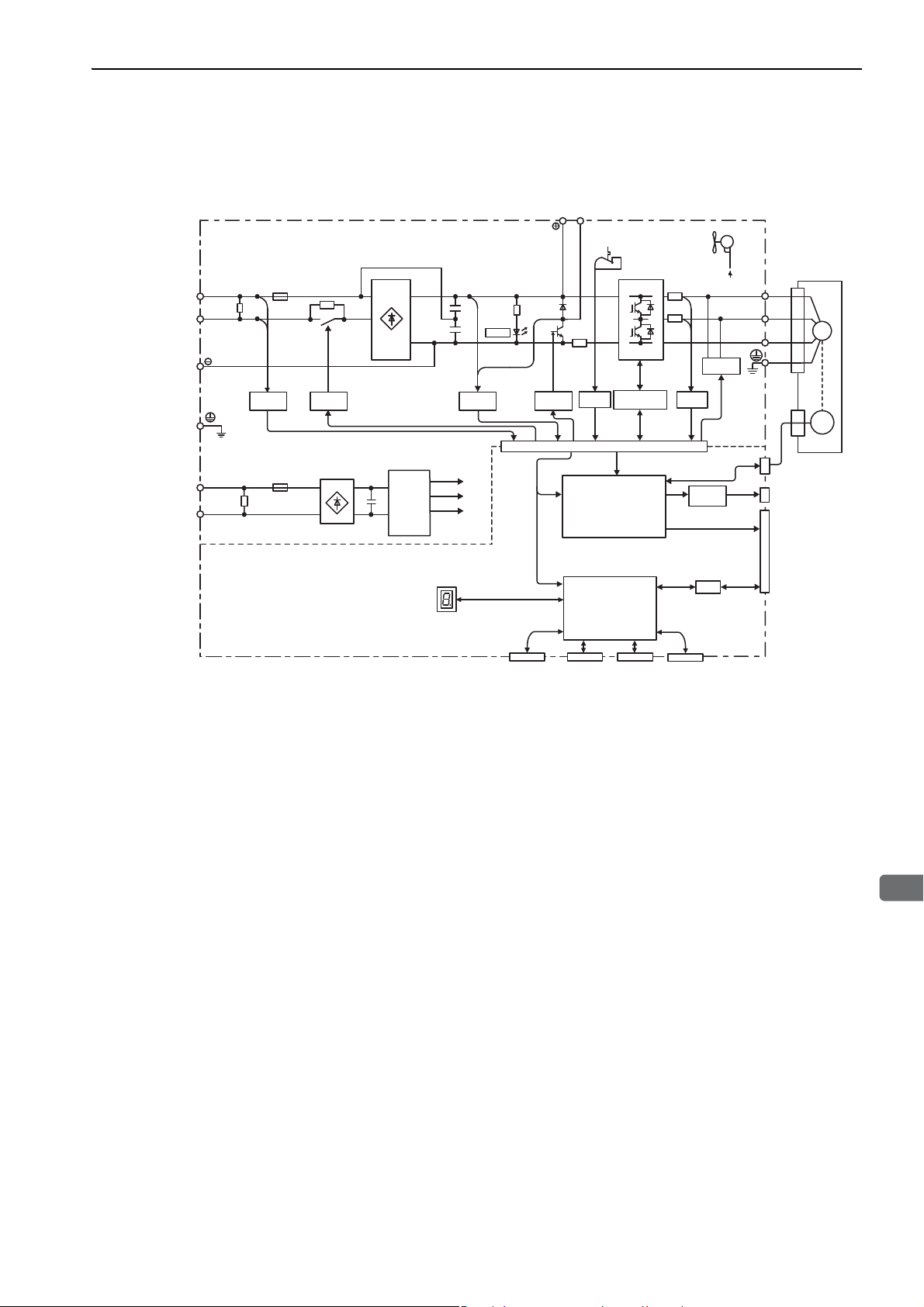
1.5 SERVOPACK Internal Block Diagrams
1.5.1 Single-phase 100 V, SGDV-R70FE5A, -R90FE5A, -2R1FE5A Models
Main circuit
power supply
Control power
supply
* This external input signal is used by the option module.
For details, refer to the manual of the connected option module.
L1
L2
L1C
L2C
Varistor
Varistor
Voltage
sensor
Relay
drive
+
–
Control
power
supply
Panel display
+
–
+
–
Voltage
sensor
±12 V
+5 V
+17 V
CHARGE
Command option
module
B1/ B2
Gate drive
Temperature
Gate
drive
(PWM control, etc.)
(Position/speed
calculation, etc.)
sensor
ASIC
CPU
overcurrent
protector
Current
sensor
Analog
voltage
converter
CN10*CN3 CN7 CN8
Digital
operator
Personal
computer
Signal for safety function
Fan
+
Dynamic
brake circuit
I/O
12 V
CN2
CN5
CN1
U
V
W
Servomotor
ENC
Analog monitor
output
Encoder output
pulse
I/O signal
M
1-7
Page 29

1 Outline
L1
L2
L1C
L2C
B1/ B2
U
V
W
CHARGE
M
ENC
+12 V
±12 V
+5 V
+17 V
Control
power
supply
Current
sensor
Dynamic
brake circuit
Servomotor
Gate
drive
Voltage
sensor
Voltage
sensor
Varistor
Varistor
Gate drive
overcurrent
protector
Temperature
sensor
Relay
drive
Fan
+
–
+
–
+
–
Control power
supply
Main circuit
power supply
CN10*CN3 CN7 CN8
CPU
(Position/speed
calculation, etc.)
Panel display
Digital
operator
Personal
computer
Signal for safety function
Command option
module
* This external input signal is used by the option module.
For details, refer to the manual of the connected option module.
CN2
I/O
CN1
CN5
Encoder output
pulse
Analog monitor
output
ASIC
(PWM control, etc.)
Analog
voltage
converter
I/O signal
L1
B1/ B2 B3
L2
L3
1
2
L1C
L2C
U
V
W
ENC
M
CHARGE
+17 V
±12 V
+5 V
Current
sensor
Dynamic
brake circuit
Servomotor
Gate
drive
Voltage
sensor
Voltage
sensor
Varistor
Varistor
Gate drive
overcurrent
protector
Temperature
sensor
Relay
drive
Control
power
supply
+
–
+
–
Main circuit
power supply
Control power
supply
+12 V
Fan
CN10*CN3 CN7 CN8
CPU
(Position/speed
calculation, etc.)
Panel display
Digital
operator
Personal
computer
Signal for safety function
Command option
module
* This external input signal is used by the option module.
For details, refer to the manual of the connected option module.
CN2
I/O
CN1
CN5
Encoder output
pulse
Analog monitor
output
ASIC
(PWM control, etc.)
Analog
voltage
converter
I/O signal
1.5.2 Single-phase 100 V, SGDV-2R8FE5A Model
1.5.2 Single-phase 100 V, SGDV-2R8FE5A Model
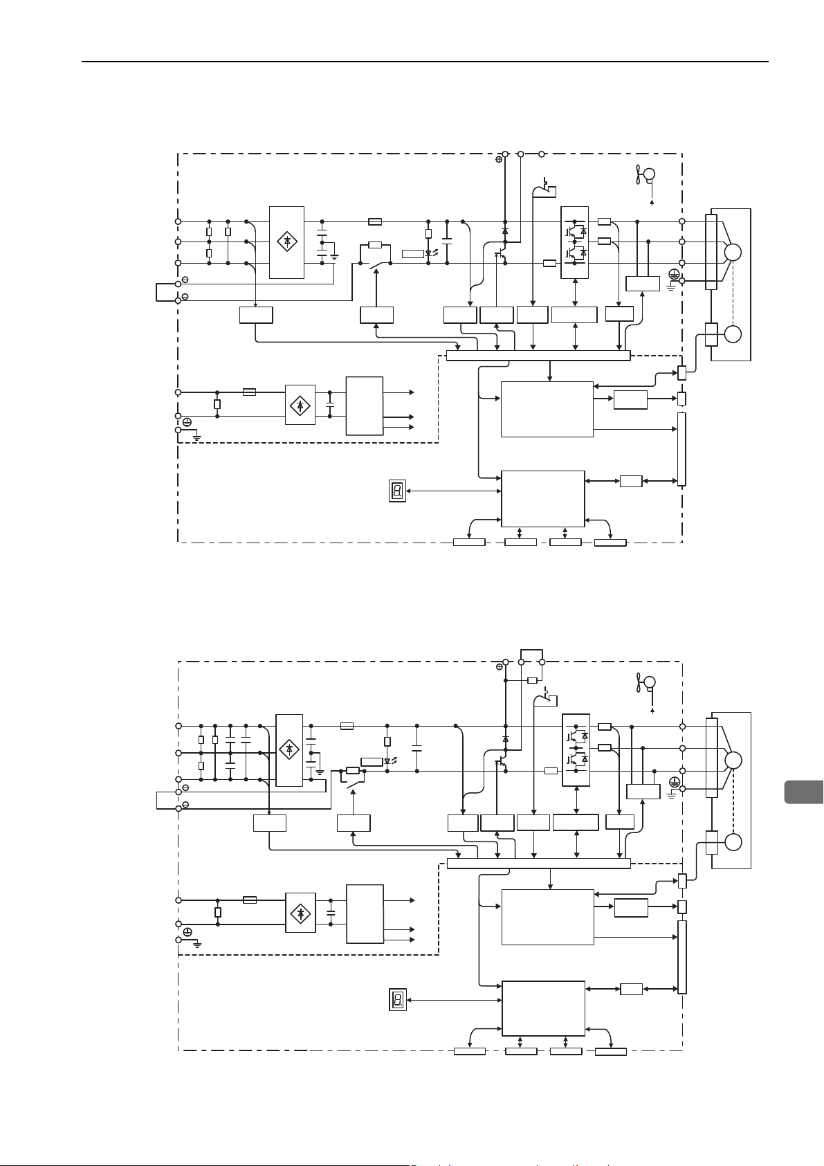
1.5.3 Three-phase 200 V, SGDV-R70AE5A, -R90AE5A, -1R6AE5A Models
1-8
Page 30
1
Outline
1.5.4 Three-phase 200 V, SGDV-2R8AE5A Model
1.5 SERVOPACK Internal Block Diagrams
Main circuit
power supply
Control power
supply
* This external input signal is used by the option module.
For details, refer to the manual of the connected option module.
L1
L2
L3
1
2
L1C
L2C
Varistor
Varistor
Voltage
sensor
+
–
Relay
drive
Control
power
supply
CHARGE
Panel display
+17 V
+5 V
±12 V
B1/ B2 B3
+
–
Voltage
sensor
Gate
Temperature
drive
(PWM control, etc.)
(Position/speed
calculation, etc.)
sensor
ASIC
CPU
Gate drive
overcurrent
protector
CN10*CN3 CN7 CN8
Command option
module
Digital
operator
Personal
computer
Fan
+12 V
Dynamic
brake circuit
Current
sensor
CN2
CN5
Analog
voltage
converter
CN1
I/O
Signal for safety function
U
V
W
Servomotor
ENC
Analog monitor
output
Encoder output
pulse
I/O signal
M
1.5.5 Three-phase 200 V, SGDV-3R8AE5A, -5R5AE5A, -7R6AE5A Models
Main circuit
power supply
Control power
supply
L1
L2
L3
1
2
L1C
L2C
Varistor
Varistor
Voltage
sensor
B1/ B2 B3
+
+17 V
+5 V
±12 V
–
Voltage
sensor
Gate
Temperature
drive
(PWM control, etc.)
(Position/speed
calculation, etc.)
sensor
CPU
ASIC
Gate drive
overcurrent
protector
CHARGE
Relay
drive
Control
+
power
–
supply
Panel display
Current
sensor
Analog
voltage
converter
Dynamic
brake circuit
I/O
Fan
±12 V
CN2
CN5
CN1
U
V
W
Analog monitor
output
Encoder output
pulse
I/O signal
Servomotor
M
ENC
CN10*CN3 CN7 CN8
Command option
module
Digital
operator
Personal
computer
Signal for safety function
* This external input signal is used by the option module.
For details, refer to the manual of the connected option module.
1-9
Page 31

1 Outline
L1
B1/ B2 B3
L2
L3
1
2
L1C
L2C
U
V
W
ENC
M
CHARGE
+15 V × 4
±12 V
+5 V
Current
sensor
Dynamic
brake circuit
Servomotor
Gate drive
Overheat protector,
overcurrent protector
Voltage
sensor
Voltage
sensor
Varistor
Varistor
Relay
drive
Fan
Control
power
supply
±12 V
+
–
+
–
Main circuit
power supply
Control power
supply
CN2
I/O
CN1
CN5
Encoder output
pulse
Analog monitor
output
ASIC
(PWM control, etc.)
Analog
voltage
converter
I/O signal
CN10*CN3 CN7 CN8
CPU
(Position/speed
calculation, etc.)
Panel display
Digital
operator
Personal
computer
Signal for safety function
Command option
module
* This external input signal is used by the option module.
For details, refer to the manual of the connected option module.
L1
B1/ B2 B3
L2
L3
1
2
L1C
L2C
U
V
W
ENC
M
CHARGE
+
–
+15 V × 4
±12 V
+5 V
Current
sensor
Dynamic
brake circuit
Servomotor
Gate drive
Voltage
sensor
Overheat protector,
overcurrent protector
Voltage
sensor
Varistor
Varistor
Relay
drive
Fan 2 Fan 1
Control
power
supply
±12 V ±12 V
+
–
Main circuit
power supply
Control power
supply
CN2
I/O
CN1
CN5
Encoder output
pulse
Analog monitor
output
ASIC
(PWM control, etc.)
Analog
voltage
converter
I/O signal
CN10*CN3 CN7 CN8
* This external input signal is used by the option module.
For details, refer to the manual of the connected option module.
CPU
(Position/speed
calculation, etc.)
Panel display
Digital
operator
Personal
computer
Signal for safety function
Command option
module
1.5.6 Three-phase 200 V, SGDV-120AE5A Model
1.5.6 Three-phase 200 V, SGDV-120AE5A Model
1.5.7 Three-phase 200 V, SGDV-180AE5A, -200AE5A Models
1-10
Page 32

1
Outline
1.5.8 Three-phase 200 V, SGDV-330AE5A Model
L1
B1/ B2 B3
L2
L3
1
2
L1C
L2C
U
V
W
ENC
M
CHARGE
Varistor
+
–
+
–
+15 V × 4
±12 V
+5 V
Current
sensor
Dynamic
brake circuit
Servomotor
Gate drive
Voltage
sensor
Voltage
sensor
Varistor
Temperature
sensor
Thyristor
drive
Fan 2 Fan 1
Overheat protector,
overcurrent protector
Control
power
supply
±12 V ±12 V
Main circuit
power supply
Control power
supply
I/O signal
CN2
I/O
CN1
CN5
Encoder output
pulse
Analog monitor
output
ASIC
(PWM control, etc.)
Analog
voltage
converter
CN10*CN3 CN7 CN8
* This external input signal is used by the option module.
For details, refer to the manual of the connected option module.
CPU
(Position/speed
calculation, etc.)
Panel display
Digital
operator
Personal
computer
Signal for safety function
Command option
module
1.5 SERVOPACK Internal Block Diagrams
1.5.9 Three-phase 200 V, SGDV-550AE5A Models
Varistor
Main circuit
power supply
Control power
supply
L1
L2
L3
L1C
L2C
Varistor
Voltage
sensor
Thyristor
drive
+
–
Control
power
supply
CHARGE
+15 V × 4
+5 V
12 V
±
Panel display
+
–
Voltage
sensor
B1/ B2
Overheat protector,
overcurrent protector
(PWM control, etc.)
(Position/speed
calculation, etc.)
Fan 1 Fan 2 Fan 3
±
12 V ±12 V ±12 V
Servomotor
U
V
W
Temperature
sensor
Current
sensor
Dynamic
brake circuit
Gate
drive
M
ENC
CN2
CN5
ASIC
CPU
Analog
voltage
converter
I/O
CN1
Analog monitor
output
Encoder output
pulse
I/O signal
* This external input signal is used by the option module.
For details, refer to the manual of the connected option module.
CN10*CN3 CN7 CN8
Command option
module
Digital
operator
Personal
computer
Signal for safety function
1-11
Page 33

1 Outline
L1
B1/ B2 B3
L2
L3
1
2
+24 V
0 V
U
V
W
ENC
M
CHARGE
Command option
module
CN10*CN3 CN7 CN8
CPU
(Position/speed
calculation, etc.)
Panel display
Digital
operator
Personal
computer
Signal for safety function
* This external input signal is used by the option module.
For details, refer to the manual of the connected option module.
+
–
+15 V × 4
±12 V
+
–
+
–
+5 V
Current
sensor
Dynamic
brake circuit
Servomotor
Gate
drive
Voltage
sensor
Voltage
sensor
Varistor
Relay
drive
Fan
Control
power
supply
Overheat protector,
overcurrent protector
±12 V
Main circuit
power supply
Control power
supply
(The 24 VDC
power supply is
not included.)
CN2
I/O
CN1
CN5
Encoder output
pulse
Analog monitor
output
ASIC
(PWM control, etc.)
Analog
voltage
converter
I/O signal
L1
B1/ B2 B3
L2
L3
1
2
+24 V
0 V
U
V
W
ENC
M
CHARGE
+15 V × 4
+5 V
±12 V
+
–
+
–
Current
sensor
Servomotor
Gate
drive
Voltage
sensor
Voltage
sensor
Relay
drive
Control
power
supply
Overheat protector,
overcurrent protector
Dynamic
brake circuit
Varistor
±12 V ±12 V
Fan 1 Fan 2
+
–
Main circuit
power supply
Control power
supply
(The 24 VDC
power supply is
not included.)
CN2
I/O
CN1
CN5
Encoder output
pulse
Analog monitor
output
ASIC
(PWM control, etc.)
Analog
voltage
converter
I/O signal
CN10*CN3 CN7 CN8
CPU
(Position/speed
calculation, etc.)
Panel display
Digital
operator
Personal
computer
Signal for safety function
Command option
module
* This external input signal is used by the option module.
For details, refer to the manual of the connected option module.
1.5.10 Three-phase 400 V, SGDV-1R9DE5A, -3R5DE5A, -5R4DE5A Models
1.5.10 Three-phase 400 V, SGDV-1R9DE5A, -3R5DE5A, -5R4DE5A Models
1.5.11 Three-phase 400 V, SGDV-8R4DE5A, -120DE5A Models
1-12
Page 34

1
Outline
1.5.12 Three-phase 400 V, SGDV-170DE5A Model
L1
B1/ B2 B3
L2
L3
1
2
+24 V
0 V
U
V
W
ENC
M
CHARGE
+15 V × 4
+5 V
±12 V
+
–
+
–
Current
sensor
Servomotor
Gate
drive
Voltage
sensor
Voltage
sensor
Relay
drive
Control
power
supply
Overheat protector,
overcurrent protector
Dynamic
brake circuit
±12 V
Fan
Varistor
+
–
Main circuit
power supply
Control power
supply
(The 24 VDC
power supply is
not included.)
CN2
I/O
CN1
CN5
Encoder output
pulse
Analog monitor
output
ASIC
(PWM control, etc.)
Analog
voltage
converter
I/O signal
CN10*CN3 CN7 CN8
* This external input signal is used by the option module.
For details, refer to the manual of the connected option module.
CPU
(Position/speed
calculation, etc.)
Panel display
Digital
operator
Personal
computer
Signal for safety function
Command option
module
1.5 SERVOPACK Internal Block Diagrams
1.5.13 Three-phase 400 V, SGDV-260DE5A Model
Varistor
Main circuit
power supply
Control power
supply
(The 24 VDC
power supply is
not included.)
L1
L2
L3
1
2
+24 V
0 V
Voltage
sensor
+
–
Relay
drive
Control
power
supply
Panel display
+
–
+
–
+15 V × 4
+5 V
±12 V
CHARGE
B1/ B2
Voltage
sensor
Overheat protector,
overcurrent protector
Gate
drive
ASIC
(PWM control, etc.)
CPU
(Position/speed
calculation, etc.)
Fan 1 Fan 2 Fan 3
+24 V +24 V +24 V
Current
sensor
Dynamic
brake circuit
Analog
voltage
converter
I/O
CN2
CN5
CN1
Servomotor
U
V
W
Analog monitor
output
Encoder output
pulse
I/O signal
M
ENC
CN10*CN3 CN7 CN8
Signal for safety function
* This external input signal is used by the option module.
Command option
module
Digital
operator
Personal
computer
For details, refer to the manual of the connected option module.
1-13
Page 35

1 Outline
Power supply
Single-phase 100 VAC
Noise filter
Molded-case
circuit breaker
(MCCB)
Protects the power
line by shutting the
circuit OFF when
overcurrent is
detected.
Eliminates
external noise from
the power line.
Magnetic
contactor
Turns the servo
ON and OFF.
Install a surge
absorber.
Regenerative
resistor*
I/O signal cable
Connection cable
for digital operator
Connection cable
for personal computer
Digital
operator
Personal
computer
Linear scale
(not included)
Connection cable
for linear scale
Serial converter unit
Servomotor main
circuit cable
Connection cable
for hall sensor
Servomotor with core
Connection cable for
serial converter unit
Safety function
devices
Host controller
When not using the safety function,
use the SERVOPACK with the safety
function’s jumper connector inserted.
When using the safety function,
use the safety connection cable.
Safety
connection cable
SGDV-FE5A
SERVOPACK
Option Module
R T
1.6.1 Connecting to SGDV-FE5A SERVOPACK
1.6 Examples of Servo System Configurations
This section describes examples of basic servo system configuration.
1.6.1 Connecting to SGDV-FE5A SERVOPACK
1-14
∗ Before connecting an external regenerative resistor to the SERVOPACK, refer to 3.7 Connecting Regenerative Resis-
tors.
Page 36

1
Outline
1.6.2 Connecting to SGDV-AE5A SERVOPACK
(1) Using a Three-phase, 200-V Power Supply
Power supply
Three-phase 200 VAC
R S T
Molded-case
circuit breaker
(MCCB)
Protects the power
line by shutting the
circuit OFF when
overcurrent is
detected.
Noise filter
Eliminates
external noise from
the power line.
Magnetic
contactor
Turns the servo
ON and OFF.
Install a surge
absorber.
SGDV-AE5A
SERVOPACK
Option Module
Connection cable
for digital operator
1.6 Examples of Servo System Configurations
Digital
operator
Personal
computer
Regenerative
resistor∗
Servomotor main
circuit cable
Connection cable for
serial converter unit
Serial converter unit
Connection cable
for linear scale
Linear scale
(not included)
Connection cable
for personal computer
I/O signal cable
Host controller
When not using the safety function,
use the SERVOPACK with the safety
function’s jumper connector inserted.
When using the safety function,
use the safety connection cable.
Safety
connection cable
Safety function
devices
Connection cable
for hall sensor
Servomotor with core
∗ Before connecting an external regenerative resistor to the SERVOPACK, refer to 3.7 Connecting Regenerative Resis-
tors.
1-15
Page 37

1 Outline
RT
Linear scale
(not included)
Connection cable
for linear scale
Connection cable
for hall sensor
Servomotor with core
Serial converter unit
Connection cable for
serial converter unit
Regenerative
resistor∗
Noise filter
Molded-case
circuit breaker
(MCCB)
Magnetic
contactor
Power supply
Single-phase 200 VAC
Protects the power
line by shutting the
circuit OFF when
overcurrent is
detected.
Eliminates
external noise from
the power line.
Turns the servo
ON and OFF.
Install a surge
absorber.
I/O signal cable
Connection cable
for digital operator
Connection cable
for personal computer
Digital
operator
Personal
computer
Servomotor main
circuit cable
Safety function
devices
Host controller
When not using the safety function,
use the SERVOPACK with the safety
function’s jumper connector inserted.
When using the safety function,
use the safety connection cable.
Safety
connection cable
SGDV-AE5A
SERVOPACK
Option Module
1.6.2 Connecting to SGDV-AE5A SERVOPACK
(2) Using a Single-phase, 200-V Power Supply
The Σ-V Series 200 V SERVOPACK generally specifies a three-phase power input but some models can be
used with a single-phase 200 V power supply. Refer to 3.1.3 Using the SERVOPACK with Single-phase, 200 V
Power Input for details.
1-16
∗ Before connecting an external regenerative resistor to the SERVOPACK, refer to 3.7 Connecting Regenerative Resis-
tors.
Page 38

1
Outline
R S T
Magnetic
contactor
I/O signal cable
Power supply
Three-phase 400 VAC
Turns the servo
ON and OFF.
Install a surge
absorber.
Connection cable
for digital operator
Connection cable
for personal computer
Digital
operator
Personal
computer
Regenerative
resistor
∗
2
Linear scale
(not included)
Connection cable
for linear scale
Serial converter unit
Connection cable for
serial converter unit
Connection cable
for hall sensor
Servomotor with core
DC power
supply (24 VDC)
∗
1
Servomotor main
circuit cable
Noise filter
Molded-case
circuit breaker
(MCCB)
Protects the power
line by shutting
the circuit OFF when
overcurrent is
detected.
Eliminates
external noise from
the power line.
Safety function
devices
Host controller
When not using the safety function,
use the SERVOPACK with the safety
function’s jumper connector inserted.
When using the safety function,
use the safety connection cable.
Safety
connection cable
SGDV-DE5A
SERVOPACK
Option Module
1.6.3 Connecting to SGDV-DE5A SERVOPACK
1.6 Examples of Servo System Configurations
∗1. Use a 24-VDC power supply with double insulation or reinforced insulation. (The power supply is not included.)
∗2. Before connecting an external regenerative resistor to the SERVOPACK, refer to 3.7 Connecting Regenerative Resis-
tors.
1-17
Page 39

1 Outline
SGDV
Series
SGDV Σ-V Series
1st + 2nd + 3rd digits: Current
Vol tage Code
Max. Allowable
Motor Capacity
(kW)
100 V
R70 0.05
R90 0.1
2R1 0.2
2R8 0.4
200 V
R70
*1
0.05
R90
*1
0.1
1R6
*1
0.2
2R8
*1
0.4
3R8 0.5
5R5
*1
0.75
7R6 1
120
1.5
180 2
200 3
330 5
550
*2
7.5
400 V
1R9 0.5
3R5 1
5R4 1.5
8R4 2
120 3
170 5
260
*2
7.5
4th digit: Voltage
Code Voltag e
F 100 V
A 200 V
D 400 V
5th + 6th digits: Interface Specifications
Code Interface
E1
Command Option-attachable Rotational
Servomotor
E5
Command Option-attachable Linear Servomotor
11th + 12th digits: Software
Specification
Code Specification
00 Standard
–
7th digit: Design
Revision Order
1st + 2nd +
3rd digits
4th
digit
5th + 6th
digits
7th
digit
2R8 A
E5
A
8th + 9th +
10th digits
000
8th + 9th + 10th digits: Hardware Specifications
Code Specifications
000 Base-mounted (standard)
001
Rack-mounted
*2
002 Va r n is h e d
003
Rack-mounted
*2
and Varnished
020
Dynamic brake (DB)
*3
11th + 12th
digits
00
13th
digit
0
13th digit: Parameter
Specification
Code Specification
0 Standard
1.7 SERVOPACK Model Designation
This section shows SERVOPACK model designation.
1-18
∗1. These amplifiers can be powered with single or three-phase.
∗2. SGDV-550A and -260D are duct-ventilated types.
∗3. A resistor for the dynamic brake is not included. An external resistor for the dynamic brake can only be used with
Note: If the option codes digits 8 to 13 are all zeros, they are omitted.
400-V SERVOPACKs.
Page 40

1.8 Servo Drive Maintenance and Inspection
1
Outline
1.8 Servo Drive Maintenance and Inspection
This section describes the inspection and maintenance of a servo drive.
1.8.1 SERVOPACK Inspection
For inspection and maintenance of the SERVOPACK, follow the inspection procedures in the following table
at least once every year. Other routine inspections are not required.
Item Frequency Procedure Comments
Exterior
At least once a year
Loose Screws
1.8.2 SERVOPACK’s Parts Replacement Schedule
The following electric or electronic parts are subject to mechanical wear or deterioration over time. To avoid
failure, replace these parts at the frequency indicated.
Check for dust, dirt, and oil
on the surfaces.
Check for loose terminal
block and connector
screws.
Clean with a cloth or compressed air.
Tighten any loose screws.
Refer to the standard replacement period in the following table and contact your Yaskawa representative.
After an examination of the part in question, we will determine whether the parts should be replaced or not.
The parameters of any SERVOPACKs overhauled by Yaskawa are reset to the factory
settings before shipping. Be sure to confirm that the parameters are properly set before
starting operation.
Part Standard Replacement Period
Cooling Fan 4 to 5 years
Smoothing Capacitor 7 to 8 years
Other Aluminum Electrolytic Capacitor 5 years
Relays –
Fuses 10 years
Note: The standard replacement period is given for usage under the following operating conditions.
• Surrounding air temperature: Annual average of 30°C
• Load factor: 80% max.
• Operation rate: 20 hours/day max.
1-19
Page 41

1 Outline
1.8.3 Servomotor Inspection
1.8.3 Servomotor Inspection
The AC servomotor is brushless and simple daily inspection is sufficient. Use the inspection frequencies given
in the following table as a guide. Determine the most appropriate inspection frequency from the actual usage
conditions and the environment.
Inspected Item
Vibration and
Noise Check
Appearance
Inspection
Insulation
Resistance Measurement
Oil Seal
Replacement
Overhaul
∗ Measure the insulation resistance between the U, V, or W phase on the servomotor’s power line and the frame ground.
Inspection Frequency
or Interval
Daily
Depends on amount of
dirt.
At least once a year
At least once every 5,000
hours
At least once every 5
years or 20,000 hours
Inspection or Maintenance
Procedure
Inspect by touching and listening
to the servomotor.
Clean with a cloth or compressed
air.
Disconnect the servomotor from
the SERVOPACK and measure
the insulation resistance with a
500 V insulation resistance
meter.* The servomotor is normal
if the resistance is higher than 10
MΩ.
Contact your Yaskawa represen-
tative.
Contact your Yaskawa represen-
tative.
Remark
There should be no more vibration
or noise than normal.
−
• If the resistance is 10 MΩ or
lower, contact your Yaskawa representative.
• Do not measure the insulation
resistance of the encoder or perform a withstand test on it.
Only necessary if the servomotor
has an oil seal.
−
1-20
Page 42

2
Panel Display and Operation of Digital Operator
2
Panel Display and
Operation of Digital Operator
2.1 Panel Display . . . . . . . . . . . . . . . . . . . . . . . . . . . . . . . . . . . . . . . . . . . . . .2-2
2.1.1 Status Display . . . . . . . . . . . . . . . . . . . . . . . . . . . . . . . . . . . . . . . . . . . . . . . . . . . . . . . 2-2
2.1.2 Alarm and Warning Display . . . . . . . . . . . . . . . . . . . . . . . . . . . . . . . . . . . . . . . . . . . . . 2-2
2.1.3 Hard Wire Base Block Display . . . . . . . . . . . . . . . . . . . . . . . . . . . . . . . . . . . . . . . . . . 2-2
2.1.4 Overtravel Display . . . . . . . . . . . . . . . . . . . . . . . . . . . . . . . . . . . . . . . . . . . . . . . . . . . .2-2
2.2 Operation of Digital Operator . . . . . . . . . . . . . . . . . . . . . . . . . . . . . . . . . . 2-3
2.3 Utility Functions (Fn) . . . . . . . . . . . . . . . . . . . . . . . . . . . . . . . . . . . .2-3
2.4 Parameters (Pn) . . . . . . . . . . . . . . . . . . . . . . . . . . . . . . . . . . . . . . .2-4
2.4.1 Parameter Classification . . . . . . . . . . . . . . . . . . . . . . . . . . . . . . . . . . . . . . . . . . . . . . . 2-4
2.4.2 Notation for Parameters . . . . . . . . . . . . . . . . . . . . . . . . . . . . . . . . . . . . . . . . . . . . . . . 2-4
2.4.3 Setting Parameters . . . . . . . . . . . . . . . . . . . . . . . . . . . . . . . . . . . . . . . . . . . . . . . . . . . 2-5
2.5 Monitor Displays (Un) . . . . . . . . . . . . . . . . . . . . . . . . . . . . . . . . . . .2-7
2-1
Page 43

2 Panel Display and Operation of Digital Operator
Status
Display
Unlit Unlit Unlit Unlit
Overtravel at forward direction (P-OT)
Current
status
Current
status
Current
status
1
Overtravel at reverse direction (N-OT)
2
Overtravel at forward/reverse direction
3
2.1.1 Status Display
2.1 Panel Display
You can use the panel display on the SERVOPACK to check the status of the servo drive.
Also, if an alarm or warning occurs, its alarm or warning number is displayed.
2.1.1 Status Display
The display shows the following status.
Display Meaning
Movement Detection (/TGON)
Lights if motor speed exceeds the value set in Pn581. (Factory setting: 20 mm/s)
Baseblock
Lights for baseblock (Servomotor power OFF).
Reference Input
Lights when a reference is being input.
Command Option Module Communications Status Display
Lights when communications with the command option module are normal.
2.1.2 Alarm and Warning Display
If an alarm or warning occurs, the display will change in the following order.
Example: Alarm A.E60
Status
Display
Unlit Unlit Unlit Unlit Unlit
2.1.3 Hard Wire Base Block Display
If a hard wire base block (HWBB) occurs, the display will change in the following order.
2.1.4 Overtravel Display
If overtraveling occurs, the display will change in the following order.
2-2
Page 44

2
Panel Display and Operation of Digital Operator
2.2 Operation of Digital Operator
BB − FUNCTION−
Fn002:JOG
Fn003:Z− Search
Fn004:Program JOG
Fn005:Prm Init
BB − Z − Search−
Un000=0 00000
Un002=0 00000
Un003=0 0000000774
Un00D=0 0000000000
Parameter
key
key
Pn000
n.
0
Linear scale
counting up
Linear scale
counting down
n.
1
Linear scale
counting down
Linear scale
counting up
Operation examples of utility functions (Fn), parameters (Pn) and monitor displays (Un)
when using a digital operator are described in this chapter.
Operations can be also performed with SigmaWin+.
2.2 Operation of Digital Operator
For more information on the usage of the digital operator, refer to
Digital Operator (No.: SIEP S800000 55).
2.3 Utility Functions (Fn)
The utility functions are related to the setup and adjustment of the SERVOPACK.
The digital operator shows numbers beginning with Fn.
The following table outlines the procedures necessary for an origin search (Fn003).
Step Display after Operation Keys Operation
1
2
RUN − Z − Search−
Un000=0 00000
3
Un002=0 00000
Un003=0 0000000774
Un00
D=0 0000000000
Σ
-V Series USER’S MANUAL Operation of
Press the Key to view the main menu for the utility function.
Use the or Key to move through the list and
select Fn003.
Press the Key. The display changes to the Fn003
execution display.
Press the Key.
The status display changes from "BB" to "RUN", and
the servomotor power turns ON.
Note: If the servomotor is already at the zero position,
"-Complete-" is displayed.
Pressing the Key will run the servomotor in the
forward direction. Pressing the Key will run the
servomotor in the reverse direction. The movement
direction of the servomotor changes according to the
setting of Pn000.0 as shown in the following table.
RUN − Complete−
Un000=0 00000
4
Un002=0 00000
Un003=0 0000000000
Un00D=0 0000001D58
Note: Forward movement is the linear scale counting
Press the or Key until the servomotor stops.
If the origin search completed normally, "-Complete-"
is displayed on the right top on the screen.
BB − Z − Search−
Un000=0 00000
5
Un002=0 00000
Un003=0 0000000000
Un00
D=0 0000001D58
BB − FUNCTION−
Fn002:JOG
6
Fn003:Z− Search
Fn004:Program JOG
Fn005:Prm Init
7 To enable the change in the setting, turn the power OFF and ON again.
When the origin search is completed, press the
Key.
The status display changes from "RUN" to "BB", and
the servomotor turns OFF. The display "-Complete-"
changes to "-Z-Search-."
Press the Key.
The display returns to the main menu of the utility
function.
up direction. For details, refer to 4.2.2 Servomo-
tor Movement Direction.
2-3
Page 45

2 Panel Display and Operation of Digital Operator
Force
(2) Parameters for Selecting Functions
2.4.1 Parameter Classification
2.4 Parameters (Pn)
This section describes the classifications, methods of notation, and settings for parameters given in this manual.
2.4.1 Parameter Classification
Parameters of the Σ-V Series SERVOPACK are classified into two types of parameters. One type of parameters is required for setting up the basic conditions for operation and the other type is required for tuning parameters that are required to adjust servomotor characteristics.
Classification Meaning Display Method Setting Method
Setup Parameters
Tuning Parameters
There are two types of notation used for parameters, one for parameter that requires a value setting (parameter
for numeric settings) and one for parameter that requires the selection of a function (parameter for selecting
functions).
Parameters required for
setup.
Parameters for tuning control gain and other parameters.
Always displayed (Factory
setting: Pn00B.0 = 0)
Set Pn00B.0 to 1.
Set each parameter individually.
There is no need to set each
parameter individually.
The notation and settings for both types of parameters are described next.
2.4.2 Notation for Parameters
(1) Parameters for Numeric Settings
Vibration Detection Sensitivity
Pn311
Parameter
number
Indicates the setting
range for the parameter.
Pn002
Setting Range Setting Unit Factory Setting When Enabled
50 to 500 1%
Indicates the
minimum setting unit
for the parameter.
Parameter Meaning When Enabled Classification
n.0
[Factory setting]
n.1
Uses the absolute linear scale as
an absolute linear scale.
Uses the absolute linear scale as
an incremental linear scale.
The control methods for which the parameters applies.
: Position control
Speed
: Speed control
Indicates the
parameter setting
before shipment.
Position
Speed
100 Immediately Tuning
Position
Indicates when a
change to the
parameter will be
effective.
Force
After restart
: Force control
Classification
Indicates the
parameter
classification.
Setup
Parameter
number
The notation “n.” indicates a parameter
for selecting functions. Each corresponds to
the setting value of that digit. The notation
shown here means that the third digit is 1.
2-4
This section explains the
selections for the function.
Page 46

2
Panel Display and Operation of Digital Operator
• Notation Example
1st digit
2nd digit
3rd digit
4th digit
Digital Operator Display
(Display Example for Pn002)
Digit Notation Setting Notation
Meaning Notation Meaning
Pn002.0
Pn002.1
Pn002.2
Pn002.3
Indicates the value for the
1st digit of parameter Pn002.
Indicates the value for the
2nd digit of parameter Pn002.
Indicates the value for the
3rd digit of parameter Pn002.
Indicates the value for the
4th digit of parameter Pn002.
Pn002.0 = x
or n.x
Pn002.1 = x
or n.x
Indicates that the value for the
1st digit of parameter Pn002 is x.
Indicates that the value for the
2nd digit of parameter Pn002 is x.
Pn002.2 = x
or n.x
Pn002.3 = x
or n.x
Indicates that the value for the
3rd digit of parameter Pn002 is x.
Indicates that the value for the
4th digit of parameter Pn002 is x.
Notation
㨚㧜㧜㧜㧜
㧮㧮ޓޓޓޓޓޓ㧙㧼㧾㧹㧛㧹㧻㧺㧙
㨁㨚㧜㧜㧜㧩ޓ㧜㧜㧜㧜㧜
㨁㨚㧜㧜㧞㧩ޓ㧜㧜㧜㧜㧜
㨁㨚㧜㧜㧤㧩ޓ㧜㧜㧜㧜㧜
㨁㨚㧜㧜㧰㧩㧜㧜㧜㧜㧜㧜㧜㧜
㧮㧮ޓޓޓޓޓޓ㧙㧼㧾㧹㧛㧹㧻㧺㧙
㨁㨚㧜㧜㧜㧩ޓ㧜㧜㧜㧜㧜
㨁㨚㧜㧜㧞㧩ޓ㧜㧜㧜㧜㧜
㨁㨚㧜㧜㧤㧩ޓ㧜㧜㧜㧜㧜
㨁㨚㧜㧜㧰㧩㧜㧜㧜㧜㧜㧜㧜㧜
㧮㧮ޓޓޓޓޓޓ㧙㧼㧾㧹㧛㧹㧻㧺㧙
㧼㨚㧜㧜㧜㧩㨚㧜㧜㧜㧜
㨁㨚㧜㧜㧞㧩ޓ㧜㧜㧜㧜㧜
㨁㨚㧜㧜㧤㧩ޓ㧜㧜㧜㧜㧜
㨁㨚㧜㧜㧰㧩㧜㧜㧜㧜㧜㧜㧜㧜
㧮㧮ޓޓޓޓޓޓ㧙㧼㧾㧹㧛㧹㧻㧺㧙
㧼㨚㧜㧜㧜㧩㨚㧜㧜㧜㧜
㨁㨚㧜㧜㧞㧩ޓ㧜㧜㧜㧜㧜
㨁㨚㧜㧜㧤㧩ޓ㧜㧜㧜㧜㧜㨜㨡㨘㨟㨑
㨁㨚㧜㧜㧰㧩㧜㧜㧜㧜㧜㧜㧜㧜
㧮㧮ޓޓޓޓޓޓ㧙㧼㧾㧹㧛㧹㧻㧺㧙
㧼㨚㧟㧤㧟㧩㧜㧜㧡㧜㧜
㨁㨚㧜㧜㧞㧩ޓ㧜㧜㧜㧜㧜
㨁㨚㧜㧜㧤㧩ޓ㧜㧜㧜㧜㧜
㨁㨚㧜㧜㧰㧩㧜㧜㧜㧜㧜㧜㧜㧜
㧮㧮ޓޓޓޓޓޓ㧙㧼㧾㧹㧛㧹㧻㧺㧙
㧼㨚㧟㧤㧟㧩㧜㧜㧡㧜㧜
㨁㨚㧜㧜㧞㧩ޓ㧜㧜㧜㧜㧜
㨁㨚㧜㧜㧤㧩ޓ㧜㧜㧜㧜㧜
㨁㨚㧜㧜㧰㧩㧜㧜㧜㧜㧜㧜㧜㧜
㧮㧮ޓޓޓޓޓޓ㧙㧼㧾㧹㧛㧹㧻㧺㧙
㧼㨚㧟㧤㧟㧩㧜㧜㧡㧜㧜
㨁㨚㧜㧜㧞㧩ޓ㧜㧜㧜㧜㧜
㨁㨚㧜㧜㧤㧩ޓ㧜㧜㧜㧜㧜
㨁㨚㧜㧜㧰㧩㧜㧜㧜㧜㧜㧜㧜㧜
㧮㧮ޓޓޓޓޓޓ㧙㧼㧾㧹㧛㧹㧻㧺㧙
㧼㨚㧟㧤㧟㧩㧜㧝㧜㧜㧜
㨁㨚㧜㧜㧞㧩ޓ㧜㧜㧜㧜㧜
㨁㨚㧜㧜㧤㧩ޓ㧜㧜㧜㧜㧜
㨁㨚㧜㧜㧰㧩㧜㧜㧜㧜㧜㧜㧜㧜
2.4.3 Setting Parameters
(1) How to Make Numeric Settings Using Parameters
The following example shows how to change the setting of parameter Pn383 (JOG speed) to 1000 mm/s.
2.4 Parameters (Pn)
Step Display after Operation Keys Operation
1
2
3
4
Press the Key to select the main menu of parameters and monitor displays.
Press the or Key to move the cursor to "Un."
Press the or Key to change "Un" to "Pn."
Press the Key to move the cursor to the column on
the right of "Pn."
Press the arrow keys to display "Pn383".
5
To move the cursor to different columns: ,
Key
To change the settings: , Key
6
7
8
Press the Key to move the cursor to the one’s
place of Pn383.
Press the Key twice to move the cursor to the hundred’s place of Pn383.
Press the Key five times to change the setting to
"1000."
2-5
Page 47

2 Panel Display and Operation of Digital Operator
㧮㧮ޓޓޓޓޓޓ㧙㧼㧾㧹㧛㧹㧻㧺㧙
㧼㨚㧟㧤㧟㧩㧜㧝㧜㧜㧜
㨁㨚㧜㧜㧞㧩ޓ㧜㧜㧜㧜㧜
㨁㨚㧜㧜㧤㧩ޓ㧜㧜㧜㧜㧜
㨁㨚㧜㧜㧰㧩㧜㧜㧜㧜㧜㧜㧜㧜
㧮㧮ޓޓޓޓޓޓ㧙㧼㧾㧹㧛㧹㧻㧺㧙
㨁㨚㧜㧜㧜㧩ޓ㧜㧜㧜㧜㧜
㨁㨚㧜㧜㧞㧩ޓ㧜㧜㧜㧜㧜
㨁㨚㧜㧜㧤㧩ޓ㧜㧜㧜㧜㧜
㨁㨚㧜㧜㧰㧩㧜㧜㧜㧜㧜㧜㧜㧜
㧮㧮ޓޓޓޓޓޓ㧙㧼㧾㧹㧛㧹㧻㧺㧙
㨁㨚㧜㧜㧜㧩ޓ㧜㧜㧜㧜㧜
㨁㨚㧜㧜㧞㧩ޓ㧜㧜㧜㧜㧜
㨁㨚㧜㧜㧤㧩ޓ㧜㧜㧜㧜㧜
㨁㨚㧜㧜㧰㧩㧜㧜㧜㧜㧜㧜㧜㧜
㧮㧮ޓޓޓޓޓޓ㧙㧼㧾㧹㧛㧹㧻㧺㧙
㧼㨚㧜㧜㧜㧩㨚㧜㧜㧜㧜
㨁㨚㧜㧜㧞㧩ޓ㧜㧜㧜㧜㧜
㨁㨚㧜㧜㧤㧩ޓ㧜㧜㧜㧜㧜
㨁㨚㧜㧜㧰㧩㧜㧜㧜㧜㧜㧜㧜㧜
㧮㧮ޓޓޓޓޓޓ㧙㧼㧾㧹㧛㧹㧻㧺㧙
㧼㨚㧜㧜㧜㧩㨚㧜㧜㧜㧜
㨁㨚㧜㧜㧞㧩ޓ㧜㧜㧜㧜㧜
㨁㨚㧜㧜㧤㧩ޓ㧜㧜㧜㧜㧜
㨁㨚㧜㧜㧰㧩㧜㧜㧜㧜㧜㧜㧜㧜
㧮㧮ޓޓޓޓޓޓ㧙㧼㧾㧹㧛㧹㧻㧺㧙
㧼㨚㧜㧜㧤㧩㨚㧠㧜㧜㧜
㨁㨚㧜㧜㧞㧩ޓ㧜㧜㧜㧜㧜
㨁㨚㧜㧜㧤㧩ޓ㧜㧜㧜㧜㧜
㨁㨚㧜㧜㧰㧩㧜㧜㧜㧜㧜㧜㧜㧜
㧮㧮ޓޓޓޓޓޓ㧙㧼㧾㧹㧛㧹㧻㧺㧙
㧼㨚㧜㧜㧤㧩㨚㧠㧜㧜㧜
㨁㨚㧜㧜㧞㧩ޓ㧜㧜㧜㧜㧜
㨁㨚㧜㧜㧤㧩ޓ㧜㧜㧜㧜㧜
㨁㨚㧜㧜㧰㧩㧜㧜㧜㧜㧜㧜㧜㧜
㧮㧮ޓޓޓޓޓޓ㧙㧼㧾㧹㧛㧹㧻㧺㧙
㧼㨚㧜㧜㧤㧩㨚
㧠
㧜㧜㧜
㨁㨚㧜㧜㧞㧩ޓ㧜㧜㧜㧜㧜
㨁㨚㧜㧜㧤㧩ޓ㧜㧜㧜㧜㧜
㨁㨚㧜㧜㧰㧩㧜㧜㧜㧜㧜㧜㧜㧜
㧮㧮ޓޓޓޓޓޓ㧙㧼㧾㧹㧛㧹㧻㧺㧙
㧼㨚㧜㧜㧤㧩㨚㧠㧜㧝㧜
㨁㨚㧜㧜㧞㧩ޓ㧜㧜㧜㧜㧜
㨁㨚㧜㧜㧤㧩ޓ㧜㧜㧜㧜㧜
㨁㨚㧜㧜㧰㧩㧜㧜㧜㧜㧜㧜㧜㧜
㧚
㧮㧮ޓޓޓޓޓޓ㧙㧼㧾㧹㧛㧹㧻㧺㧙
㧼㨚㧜㧜㧤㧩㨚㧠㧜㧝㧜
㨁㨚㧜㧜㧞㧩ޓ㧜㧜㧜㧜㧜
㨁㨚㧜㧜㧤㧩ޓ㧜㧜㧜㧜㧜
㨁㨚㧜㧜㧰㧩㧜㧜㧜㧜㧜㧜㧜㧜
㧚
2.4.3 Setting Parameters
Step Display after Operation Keys Operation
(cont’d)
9
Press the Key to write the settings.
(2) How to Select Functions Using Parameters
The following example shows how to set the function section for insufficient voltage of the application function select switch 8 (Pn008) to 1
Step Display after Operation Keys Operation
1
2
3
"detects warning and limits force by host controller."
Press the
Key to select the main menu of param-
eters and monitor displays.
Press the or Key to move the cursor to
"Un."
Press the or Key to change "Un" to "Pn."
4
5
6
7
8
9
Press the Key three times to move the cursor to
the column on the right of "Pn."
Press the Key to display "Pn008."
Press the Key to move the cursor to "Pn008.0."
Press the Key once to move the cursor to
"Pn008.1."
Press the Key to change the setting of "Pn008.1"
to "1."
Press the Key to write the settings.
2-6
Page 48

2
Panel Display and Operation of Digital Operator
2.5 Monitor Displays (Un)
㧮㧮ޓޓޓޓޓޓ㧙㧼㧾㧹㧛㧹㧻㧺㧙
㨁㨚㧜㧜㧜㧩ޓ㧜㧜㧜㧜㧜
㨁㨚㧜㧜㧞㧩ޓ㧜㧜㧜㧜㧜
㨁㨚㧜㧜㧤㧩ޓ㧜㧜㧜㧜㧜
㨁㨚㧜㧜㧰㧩㧜㧜㧜㧜㧜㧜㧜㧜
Shows the setting of Un000 (motor moving speed) as 0 mm/s.
The monitor displays can be used for monitoring the reference values, I/O signal status, and SERVOPACK
internal status.
For details, refer to 7.2 Viewing Monitor Displays.
The digital operator shows numbers beginning with Un.
The following four settings are the factory settings.
2.5 Monitor Displays (Un)
2-7
Page 49

3
Wiring and Connection
3
Wiring and Connection
3.1 Main Circuit Wiring . . . . . . . . . . . . . . . . . . . . . . . . . . . . . . . . . . . . . . . . . .3-2
3.1.1 Main Circuit Terminals . . . . . . . . . . . . . . . . . . . . . . . . . . . . . . . . . . . . . . . . . . . . . . . . . 3-2
3.1.2 Using a Standard Power Supply
(Single-phase 100 V, Three-phase 200 V, or Three-phase 400 V) . . . . . . . . . . . . . . . 3-3
3.1.3 Using the SERVOPACK with Single-phase, 200 V Power Input . . . . . . . . . . . . . . . . 3-11
3.1.4 Using the SERVOPACK with a DC Power Input . . . . . . . . . . . . . . . . . . . . . . . . . . . . 3-14
3.1.5 Using More Than One SERVOPACK . . . . . . . . . . . . . . . . . . . . . . . . . . . . . . . . . . . . 3-18
3.1.6 General Precautions for Wiring . . . . . . . . . . . . . . . . . . . . . . . . . . . . . . . . . . . . . . . . . 3-19
3.2 I/O Signal Connections . . . . . . . . . . . . . . . . . . . . . . . . . . . . . . . . . . . . . . 3-20
3.2.1 I/O Signal (CN1) Names and Functions . . . . . . . . . . . . . . . . . . . . . . . . . . . . . . . . . . 3-20
3.2.2 Safety Function Signal (CN8) Names and Functions . . . . . . . . . . . . . . . . . . . . . . . . 3-21
3.2.3 Example of I/O Signal Connections . . . . . . . . . . . . . . . . . . . . . . . . . . . . . . . . . . . . . 3-22
3.3 I/O Signal Allocations . . . . . . . . . . . . . . . . . . . . . . . . . . . . . . . . . . . . . . .3-23
3.3.1 Input Signal Allocations . . . . . . . . . . . . . . . . . . . . . . . . . . . . . . . . . . . . . . . . . . . . . . . 3-23
3.3.2 Output Signal Allocations . . . . . . . . . . . . . . . . . . . . . . . . . . . . . . . . . . . . . . . . . . . . . 3-25
3.4 Examples of Connection to Host Controller . . . . . . . . . . . . . . . . . . . . . .3-26
3.4.1 Sequence Input Circuit . . . . . . . . . . . . . . . . . . . . . . . . . . . . . . . . . . . . . . . . . . . . . . . 3-26
3.4.2 Sequence Output Circuit . . . . . . . . . . . . . . . . . . . . . . . . . . . . . . . . . . . . . . . . . . . . . . 3-27
3.5 Wiring Communications Using Command Option Modules . . . . . . . . . . 3-29
3.6 Linear Scale Connection . . . . . . . . . . . . . . . . . . . . . . . . . . . . . . . . . . . . .3-30
3.6.1 Linear Scale Signal (CN2) Names and Functions . . . . . . . . . . . . . . . . . . . . . . . . . . . 3-30
3.6.2 Serial Converter Unit . . . . . . . . . . . . . . . . . . . . . . . . . . . . . . . . . . . . . . . . . . . . . . . . . 3-30
3.6.3 Linear Scale Connection Examples . . . . . . . . . . . . . . . . . . . . . . . . . . . . . . . . . . . . . 3-33
3.7 Connecting Regenerative Resistors . . . . . . . . . . . . . . . . . . . . . . . . . . . .3-37
3.7.1 Connecting Regenerative Resistors . . . . . . . . . . . . . . . . . . . . . . . . . . . . . . . . . . . . . 3-37
3.7.2 Setting Regenerative Resistor Capacity . . . . . . . . . . . . . . . . . . . . . . . . . . . . . . . . . . 3-39
3.8 Noise Control and Measures for Harmonic Suppression . . . . . . . . . . . . 3-40
3.8.1 Wiring for Noise Control . . . . . . . . . . . . . . . . . . . . . . . . . . . . . . . . . . . . . . . . . . . . . . 3-40
3.8.2 Precautions on Connecting Noise Filter . . . . . . . . . . . . . . . . . . . . . . . . . . . . . . . . . . 3-42
3.8.3 Connecting a Reactor for Harmonic Suppression . . . . . . . . . . . . . . . . . . . . . . . . . . . 3-43
3-1
Page 50

3 Wiring and Connection
: Main circuit terminals
SGDV-1R6AE1A
3.1.1 Main Circuit Terminals
3.1 Main Circuit Wiring
The names and specifications of the main circuit terminals are given below.
Also this section describes the general precautions for wiring and precautions under special environments.
3.1.1 Main Circuit Terminals
Terminal
Symbols
L1, L2
L1, L2, L3
L1C, L2C
24V, 0V D
Main circuit power input terminals
Control power input
terminals
Name Model SGDV-
F Single-phase 100 to 115 V, +10 to -15%, 50/60 Hz
A Three-phase 200 to 230 V, +10 to -15%, 50/60 Hz
D Three-phase 380 to 480 V, +10 to -15%, 50/60 Hz
F Single-phase 100 to 115 V, +10 to -15%, 50/60 Hz
A Single-phase 200 to 230 V, +10 to -15%, 50/60 Hz
R70F, R90F, 2R1F,
2R8F, R70A, R90A,
1R6A, 2R8A
3R8A, 5R5A, 7R6A,
120A, 180A, 200A,
330A, 1R9D, 3R5D,
B1/ , B2
External regenera-
*1
tive resistor connection terminals
5R4D, 8R4D, 120D,
170D
550A, 260D
DC reactor connec-
1, 2
tion terminal for pow-
*2
er supply harmonic
A
D
suppression
B1/
2 or
U, V, W
Main circuit positive
terminal
Main circuit negative
terminal
Servomotor connection terminals
Ground terminals
(× 2)
A
D
A
D
Use for connecting to the servomotor.
Use for connecting the power supply ground terminal and servomotor ground
terminal.
Specification
±
24 VDC,
15%
If the regenerative capacity is insufficient, connect
an external regenerative resistor between B1/ and
B2.
Note: The external regenerative resistor is not
included.
If the internal regenerative resistor is insufficient,
remove the lead or shorting bar between B2 and B3
and connect an external regenerative resistor
between B1/ and B2.
Note: The external regenerative resistor is not
included.
Connect a regenerative resistor unit between B1/
and B2.
Note: The regenerative resistor unit is not included.
If a countermeasure against power supply harmonic
waves is needed, connect a DC reactor between 1
and 2.
Use when DC power supply input is used.
3-2
Page 51

3
Wiring and Connection
∗1. Do not short-circuit between B1/ and B2. It may damage the SERVOPACK.
∗2. The DC reactor connection terminals are short-circuited when the SERVOPACK is shipped from the factory: 1 and
2.
3.1.2 Using a Standard Power Supply (Single-phase 100 V, Three-phase 200 V, or Three-phase 400 V)
(1) Wire Types
Use the following type of wire for main circuit.
3.1 Main Circuit Wiring
Cable Type
Symbol Name
IV 600 V grade polyvinyl chloride insulated wire 60
HIV 600 V grade heat-resistant polyvinyl chloride insulated wire 75
Allowable Conductor Temperature °C
The following table shows the wire sizes and allowable currents for three wires. Use wires with specifications
equal to or less than those shown in the table.
•
600 V grade heat-resistant polyvinyl chloride insulated wire (HIV)
Nominal
AWG Size
20 0.5 19/0.18 39.5 6.6 5.6 4.5
19 0.75 30/0.18 26.0 8.8 7.0 5.5
18 0.9 37/0.18 24.4 9.0 7.7 6.0
16 1.25 50/0.18 15.6 12.0 11.0 8.5
14 2.0 7/0.6 9.53 23 20 16
12 3.5 7/0.8 5.41 33 29 24
10 5.5 7/1.0 3.47 43 38 31
8 8.0 7/1.2 2.41 55 49 40
6 14.0 7/1.6 1.35 79 70 57
4 22.0 7/2.0 0.85 91 81 66
Cross
Section Area
(mm
2
)
Configuration
(Number of
Wires/mm)
Conductive
Resistance
(Ω/km)
Allowable Current at Surrounding Air
Temperature (A)
30°C 40°C 50°C
Note: The values in the table are for reference only.
(2) Main Circuit Wires
This section describes the main circuit wires for SERVOPACKs.
• The specified wire sizes are for use when the three lead cables are bundled and when
the rated electric current is applied with a surrounding air temperature of 40°C.
• Use a wire with a minimum withstand voltage of 600 V for the main circuit.
• If cables are bundled in PVC or metal ducts, take into account the reduction of the
allowable current.
• Use a heat-resistant wire under high surrounding air or panel temperatures, where
polyvinyl chloride insulated wires will rapidly deteriorate.
3-3
Page 52

3 Wiring and Connection
3.1.2 Using a Standard Power Supply (Single-phase 100 V, Three-phase 200 V, or Three-phase 400 V)
Single-phase, 100 V
Te rm i na l
Symbols
L1, L2
L1C, L2C Control power input terminals HIV1.25
U, V, W
B1/ , B2
Main circuit power input terminals
Servomotor connection terminals
External regenerative resistor
connection terminals
Ground terminal HIV2.0 or larger
Name
R70 R90 2R1 2R8
HIV1.25 HIV2.0
Three-phase, 200 V
Terminal
Symbols
L1, L2, L3
L1C, L2C
U, V, W
B1/ , B2
Main circuit power input
terminals
Control power input terminals
Servomotor connection
terminals
External regenerative resistor connection terminals
Name
R70 R90 1R6 2R8 3R8 5R5 7R6 120 180 200 330 550
HIV1.25 HIV2.0 HIV3.5
HIV1.25 HIV2.0
SGDV-F
HIV1.25
HIV1.25
SGDV-A (Unit: mm2)
HIV1.25
HIV1.25
HIV
2.0
HIV
5.5
HIV
3.5
HIV
5.5
HIV
8.0
HIV
5.5
HIV
14.0
HIV
14.0
HIV
8.0
Ground terminal HIV2.0 or larger
Three-phase, 400 V
Te rm i na l
Symbols
L1, L2, L3 Main circuit power input terminals HIV1.25 HIV2.0
24V, 0V Control power input terminals HIV1.25
U, V, W Servomotor connection terminals HIV1.25 HIV2.0
B1/ , B2
External regenerative resistor connection terminals
Ground terminal HIV2.0 or larger
Name
1R9 3R5 5R4 8R4 120 170 260
SGDV-D (Unit: mm2)
HIV1.25
HIV
3.5
HIV
3.5
HIV
2.0
HIV
5.5
HIV
5.5
HIV
3.5
3-4
Page 53

3.1 Main Circuit Wiring
3
Wiring and Connection
(3) Typical Main Circuit Wiring Examples
Note the following points when designing the power ON sequence.
• The ALM (Servo Alarm) signal is output for up to five seconds when the control power supply is turned ON. Take this
into consideration when you design the power ON sequence, and turn ON the main circuit power supply to the SERVOPACK when the ALM signal is OFF (alarm cleared).
Power ON
Control power supply
ALM (Servo Alarm)
signal
Main circuit power supply
/S-RDY (Servo Ready)
signal
Servo ON command*
Motor power status
ONOFF
Alarm
Up to 5.0 s
OFF
Alarm cleared.
ON
ONOFF
ONOFF
Power supplied.Power not supplied.
∗ For details, refer to the manual for the connected command option module.
<Information>
If the servo ON state cannot be achieved by turning ON the Servo ON command, the /S-RDY signal is not
ON. Check the status of the /S-RDY signal. For details, refer to the 4.6.4 Servo Ready Output Signal (/S-
RDY).
• Design the power ON sequence so that main circuit power supply is turned OFF when an ALM (Servo Alarm) signal is
output.
• Make sure that the power supply specifications of all parts are suitable for the input power supply.
• Allow at least 1 s after the power supply is turned OFF before you turn it ON again.
• When turning ON the control power supply and the main circuit power supply, turn
them ON at the same time or turn the main circuit power supply after the control
power supply. When turning OFF the power supplies, first turn the power for the main
circuit OFF and then turn OFF the control power supply.
3-5
Page 54

3 Wiring and Connection
L1
ENC
U
V
W
M
0 V
1Ry
+
−
3
4
1D
2KM
1KM
B2
L2
CN1
1QF
R
T
+24 V
B1/
3SA
1Ry
1PL
1KM
2KM
1SA
1KM
1Ry
1KM
2SA
L1C
L2C
ALM
ALM
1FLT
1PL: Indicator lamp
1SA: Surge absorber
2SA: Surge absorber
3SA: Surge absorber
1D: Flywheel diode
1QF: Molded-case circuit breaker
1FLT: Noise filter
1KM: Magnetic contactor (for control power supply)
2KM: Magnetic contactor (for main circuit power supply)
1Ry: Relay
SERVOPACK
SGDV-F
(For servo
alarm display)
supply ON
Servo power
supply OFF
Servo power
3.1.2 Using a Standard Power Supply (Single-phase 100 V, Three-phase 200 V, or Three-phase 400 V)
The typical main circuit wiring examples are shown below.
WARNING
• Do not touch the power supply terminals after turning OFF the power. High voltage may still remain in the
SERVOPACK, resulting in electric shock. When the voltage is discharged, the charge indicator will turn
OFF. Make sure the charge indicator is OFF before starting wiring or inspections.
Single-phase 100 V, SGDV-
F (SGDV-R70F, -R90F, -2R1F, -2R8F)
3-6
Page 55

3.1 Main Circuit Wiring
3
Wiring and Connection
2KM
L1
ENC
U
V
W
M
0 V
1Ry
+
−
3
4
1D
B2
B3
L2
CN1
1KM
L1C
L3
L2C
1QF
R
S T
1FLT
+24 V
1
2
3SA
*
B1/
1PL
1KM
2KM
1SA
2SA
1KM
1Ry
1KM
ALM
ALM
1Ry
1PL: Indicator lamp
1SA: Surge absorber
2SA: Surge absorber
3SA: Surge absorber
1D: Flywheel diode
1QF: Molded-case circuit breaker
1FLT: Noise filter
1KM: Magnetic contactor (for control power supply)
2KM: Magnetic contactor (for main circuit power supply)
1Ry: Relay
SERVOPACK
SGDV-A
(For servo
alarm display)
supply ON
Servo power
supply OFF
Servo power
2KM
L1
ENC
U
V
W
M
0 V
1Ry
1D
B2
L2
1KM
L1C
L3
L2C
1QF
R
S T
1FLT
+24 V
3SA
B1/
1PL
1KM
2KM
1SA
2SA
+
−
3
4
CN1
1KM
1Ry
1KM
ALM
ALM
1Ry
SGDV-A
Regenerative
resistor unit
(For servo
alarm display)
supply ON
Servo power
supply OFF
Servo power
SERVOPACK
1QF: Molded-case circuit breaker
1FLT: Noise filter
1KM: Magnetic contactor (for control power supply)
2KM: Magnetic contactor (for main circuit power supply)
1Ry: Relay
1PL: Indicator lamp
1SA: Surge absorber
2SA: Surge absorber
3SA: Surge absorber
1D: Flywheel diode
Three-phase 200 V, SGDV-
A
• SGDV-R70A, -R90A, -1R6A, -2R8A, -3R8A, -5R5A, -7R6A, -120A, -180A, -200A, -330A
∗ For the SGDV-R70A, -R90A, -1R6A, -2R8A, terminals B2 and B3 are not short-circuited. Do not short-circuit these
terminals.
• SGDV-550A
3-7
Page 56

3 Wiring and Connection
ENC
U
V
W
M
0 V
1Ry
1D
1QF
R
S T
1FLT
+24 V
3SA
B2
B3
1
2
B1/
1PL
1KM
2KM
1SA
2SA
L1
2KM
L2
L3
24 V
+
−
1KM
0 V
+
−
3
4
CN1
1KM
1Ry
1KM
ALM
ALM
1Ry
1QF: Molded-case circuit breaker
1FLT: Noise filter
1KM: Magnetic contactor (for control power supply)
2KM: Magnetic contactor (for main circuit power supply)
1Ry: Relay
1PL: Indicator lamp
1SA: Surge absorber
2SA: Surge absorber
3SA: Surge absorber
1D: Flywheel diode
DC power
supply
24 V
(For servo
alarm display)
supply ON
Servo power
supply OFF
Servo power
SERVOPACK
SGDV-D
ENC
U
V
W
M
0 V
1Ry
1D
1QF
R
S T
1FLT
+24 V
3SA
B2
1
2
B1/
1PL
1KM
2KM
1SA
2SA
L1
2KM
L2
L3
24 V
+
−
1KM
0 V
+
−
3
4
CN1
1KM
1Ry
1KM
ALM
ALM
1Ry
SGDV-D
DC power
supply
(24 V)
Regenerative
resistor unit
(For servo
alarm display)
supply ON
Servo power
supply OFF
Servo power
SERVOPACK
1QF: Molded-case circuit breaker
1FLT: Noise filter
1KM: Magnetic contactor (for control power supply)
2KM: Magnetic contactor (for main circuit power supply)
1Ry: Relay
1PL: Indicator lamp
1SA: Surge absorber
2SA: Surge absorber
3SA: Surge absorber
1D: Flywheel diode
3.1.2 Using a Standard Power Supply (Single-phase 100 V, Three-phase 200 V, or Three-phase 400 V)
Three-phase 400 V, SGDV-
D
• SGDV-1R9D, -3R5D, -5R4D, -8R4D, -120D, -170D
3-8
• SGDV-260D
Page 57

3
Wiring and Connection
(4) Power Supply Capacities and Power Losses
The following table shows the SERVOPACK’s power supply capacities and power losses.
3.1 Main Circuit Wiring
Main
Circuit
Power
Supply
Singlephase,
100 V
Threephase,
200 V
Threephase,
400 V
Maximum
Applicable
Servomotor
Capacity
[kW]
0.05 R70F 0.2 0.66 5.4
0.1 R90F 0.3 0.91 7.8 24.8
0.2 2R1F 0.7 2.1 14.4 31.4
0.4 2R8F 1.4 2.8 25.6 42.6
0.05 R70A 0.2 0.66 5.1
0.1 R90A 0.3 0.91 7.3 24.3
0.2 1R6A 0.6 1.6 13.5 30.5
0.4 2R8A 1 2.8 24.0 41.0
0.5 3R8A 1.4 3.8 20.1
0.75 5R5A 1.6 5.5 43.8 68.8
1.0 7R6A 2.3 7.6 53.6 78.6
1.5 120A 3.2 11.6 65.8 10
2.0 180A 4 18.5 111.9
3.0 200A 5.9 19.6 113.8 161.4
5.0 330A 7.5 32.9 263.7 36 27 326.7
7.5 550A 14.6 54.7 357.8
0.5 1R9D 1.1 1.9 24.6
1.0 3R5D 2.3 3.5 46.1 81.1
1.5 5R4D 3.5 5.4 71.3 106.3
2.0 8R4D 4.5 8.4 77.9
3.0 120D 7.1 11.9 108.7 161.7
5.0 170D 11.7 16.5 161.1 36 24 221.1
7.5 260D 14.4 25.7 218.6
SERVOPACK
Model
SGDV-
Power Supply
Capacity per
SERVOPACK
[kVA]
Output
Current
[Arms]
Main
Circuit
Power
Loss
[W]
Regenerative
Resistor
Power Loss
[W]
–17
–
8
16
*1
(350)
14 21
28 25
*2
(180)
Control
Circuit
Power
Loss [W]
17
22
33 390.8
27 245.6
To ta l
Power
Loss [W]
22.4
22.1
45.1
97.8
149.9
59.6
130.9
∗1. The value in parentheses is for the JUSP-RA05-E regenerative resistor unit.
∗2. The value in parentheses is for the JUSP-RA18-E regenerative resistor unit.
Note 1. SGDV-R70F, -R90F, -2R1F, -2R8F, -R70A, -R90A, -1R6A, and -2R8A SERVOPACKs do not have built-in
regenerative resistors. Connect an external regenerative resistor if the regenerative energy exceeds the specified
value.
2. SGDV-550A and -260D SERVOPACKs do not have built-in regenerative resistors. Make sure that a regenerative
resistor unit or an external regenerative resistor is connected.
Refer to 3.7 Connecting Regenerative Resistors for details.
3. Regenerative resistor power losses are the allowable losses. Take the following actions if this value is exceeded.
• Remove the lead or shorting bar between terminals B2 and B3 on the SERVOPACK main circuit for SGDV3R8A, -5R5A, -7R6A, -120A, -180A, -200A, -330A, and 400-V SERVOPACKs.
• Install an external regenerative resistor. Refer to 3.7 Connecting Regenerative Resistors for details.
3-9
Page 58

3 Wiring and Connection
3.1.2 Using a Standard Power Supply (Single-phase 100 V, Three-phase 200 V, or Three-phase 400 V)
(5) How to Select Molded-case Circuit Breaker and Fuse Capacities
The following table shows the SERVOPACK’s current capacities and inrush current.
Use these values as a basis for selecting the molded-case circuit breaker and fuse.
Main
Circuit
Power
Supply
Singlephase,
100 V
Threephase,
200 V
Threephase,
400 V
Maximum
Applicable
Servomotor
Capacity
[kW]
0.05 R70F 0.2 1.5
0.1 R90F 0.3 2.5
0.2 2R1F 0.7 5
0.4 2R8F 1.4 10
0.05 R70A 0.2 1.0
0.1 R90A 0.3 1.0
0.2 1R6A 0.6 2.0
0.4 2R8A 1 3.0
0.5 3R8A 1.4 3.0
0.75 5R5A 1.6 6.0
1.0 7R6A 2.3 6.0
1.5 120A 3.2 7.3
3.0 200A 5.9 15
5.0 330A 7.5 25
7.5 550A 14.6 37
0.5 1R9D 1.1 1.4
1.0 3R5D 2.3 2.9
1.5 5R4D 3.5 4.3
2.0 8R4D 4.5 5.8
3.0 120D 7.1 8.6
5.0 170D 11.7 14.5 57
7.5 260D 14.4 21.7 1.5 34
SERVOPACK
Model
SGDV-
Power Supply
Capacity per
SERVOPACK
[kVA]
Current Capacity Inrush Current
Main Circuit
[Arms]
Control
Circuit
[Arms]
0.38 16.5 35
0.2
0.252.0 180A 4 9.7
0.3 65.5
1.2 17
1.4
Main Circuit
[A0-p]
33
34
Control
Circuit
[A0-p]
70
33
–
3-10
Note 1. To comply with the EU low voltage directive, connect a fuse to the input side as protection against accidents
caused by short-circuits.
Select fuses or molded-case circuit breakers that are compliant with UL standards.
The table above also provides the net values of current capacity and inrush current. Select a fuse and a moldedcase circuit breaker which meet the breaking characteristics shown below.
• Main circuit, control circuit: No breaking at three times the current values shown in the table for 5 s.
• Inrush current: No breaking at the current values shown in the table for 20 ms.
2. The following restrictions apply to UL standard compliance conditions.
SERVOPACK Model SGDV- Restrictions
180A, 200A Available rated current for modeled-case circuit breaker: 40 A or less
• Available rated current for non-time delay fuse: 70 A or less
330A
550A
260D
• Available rated current for time delay fuse: 40 A or less
• Do not use single wires.
• Available rated current for molded-case circuit breaker: 60 A or less
• Available rated current for non-time delay fuse or time delay fuse: 60 A or
less
• Available rated current for molded-case circuit breaker: 60 A or less.
• Available rated current for non-time-delay fuse: 60 A or less.
• Available rated current for time delay fuse: 35 A or less
Page 59

3
Wiring and Connection
3.1.3 Using the SERVOPACK with Single-phase, 200 V Power Input
Some models of Σ-V series three-phase 200 V power input SERVOPACK can be used also with a single-phase
200 V power supply.
The following models support a single-phase 200-V power input.
SGDV-R70A, -R90A, -1R6A, -2R8A, -5R5A
When using the SERVOPACK with single-phase, 200 V power input, set parameter Pn00B.2 to 1.
(1) Parameter Setting
Single-phase Power Input Selection
3.1 Main Circuit Wiring
When
Enabled
After restart Setup
Pn00B
Parameter Meaning
n.0
[Factory setting]
n.1
Enables use of three-phase power supply for three-phase
SERVOPACK.
Enables use of single-phase power supply for three-phase
SERVOPACK.
WARNING
• If single-phase 200 V is input to a SERVOPACK with a single-phase power input without changing the setting of Pn00B.2 to 1 (single-phase power input), a main circuit cable open phase alarm (A.F10) will be
detected.
• SERVOPACK models other than those for single-phase 200-V power input do not support single-phase
power input. If a single-phase 200 V is input to the SERVOPACK that do not support single-phase power
input, the main circuit cable open phase alarm (A.F10) will be detected.
• When using a single-phase 200 V power supply, the SGDV-R70A, -R90A, -1R6A, -2R8A, or -5R5A SERVOPACK may not be able to produce the same servomotor force-speed characteristics as using a threephase 200 V power input. Refer to the diagram of each servomotor force-speed characteristics in
Series Product Catalog (No.: KAEP S800000 42).
(2) Main Circuit Power Input Terminals
Connect a single-phase 200 V power supply of the following specifications to L1 and L2 terminals.
The specifications of the power supplies other than the main circuit power supply are the same as for threephase power supply input.
Classification
Σ
-V
Terminal
Symbols
L1, L2
*
L3
∗ Do not use L3 terminal.
Main circuit power input terminals
– None
Name Model SGDV-A
R70, R90, 1R6, 2R8, 5R5
(3) Main Circuit Wire for SERVOPACKs
Te rm i na l
Symbols
L1, L2
L1C, L2C Control power input terminals HIV1.25
U, V, W
B1/ , B2
Main circuit power input terminals
Servomotor connection terminals
External regenerative resistor
connection terminals
Ground terminal HIV2.0 or larger
Name
Specifications
Single-phase 200 to 230 V, +10 to -15%,
50/60 Hz
Model SGDV-A (Unit: mm2)
R70 R90 1R6 2R8 5R5
HIV1.25 HIV2.0
HIV1.25 HIV2.0
HIV1.25
3-11
Page 60

3 Wiring and Connection
1PL
1KM
2KM
1SA
2SA
L1
0 V
1Ry
1D
2KM
L3
B2
B3
L2
U
V
W
M
1QF
R
T
1FLT
+24 V
ENC
1
2
L1C
1KM
L2C
3SA
B1/
+
−
3
4
CN1
1KM
1Ry
1KM
ALM
ALM
1Ry
1PL
1SA
2SA
3SA
1D:
: Indicator lamp
: Surge absorber
: Surge absorber
: Surge absorber
Flywheel diode
1QF: Molded-case circuit breaker
1FLT: Noise filter
1KM: Magnetic contactor (for control power supply)
2KM: Magnetic contactor (for main circuit power supply)
1Ry: Relay
SERVOPACK
SGDV-A
(For servo
alarm display)
supply ON
Servo power
supply OFF
Servo power
3.1.3 Using the SERVOPACK with Single-phase, 200 V Power Input
(4) Wiring Example with Single-phase 200-V Power Supply Input
SERVOPACK with Single-phase, 200-V Power Supply
Applicable SERVOPACK Model: SGDV-R70A, -R90A, -1R6A, -2R8A, and -5R5A
(5) Power Supply Capacities and Power Losses
The following table shows SERVOPACK’s power supply capacities and power losses when using single-
phase 200 V power supply.
Main Circuit
Power
Supply
Maximum
Applicable
Servomotor
Capacity
SERVOPACK
Model SGDV-
[kW]
Single-phase,
200 V
Note 1. SGDV-R70A, -R90A, -1R6A, and -2R8A SERVOPACKs do not have built-in regenerative resistors. If the regen-
erative energy exceeds the specified value, connect an external regenerative resistor between B1/ and B2.
2. Regenerative resistor power losses are allowable losses. Take the following action if this value is exceeded.
• Remove the lead or shorting bar between terminals B2 and B3 on the SERVOPACK main circuit of SGDV5R5A SERVOPACKs.
• Install an external regenerative resistor between external regenerative resistor connection terminals B1/ and
0.05 R70A 0.2 0.66 5.2
0.1 R90A 0.3 0.91 7.4 24.4
0.2 1R6A 0.7 1.6 13.7 30.7
0.4 2R8A 1.2 2.8 24.9 41.9
0.75 5R5A 1.9 5.5 52.7 8 77.7
B2.
3. External regenerative resistors are not included.
Power Supply
Capacity per
SERVOPACK
[kVA]
Output
Current
[Arms]
Main
Circuit
Power
Loss
[W]
Regenerative
Resistor
Power Loss
[W]
–
Control
Circuit
Power
Loss
[W]
17
To ta l
Power
Loss
[W]
22.2
3-12
Page 61

3.1 Main Circuit Wiring
3
Wiring and Connection
(6) How to Select Molded-case Circuit Breaker and Fuse Capacities
The following table shows the SERVOPACK’s current capacities and inrush current when using single-phase
200 V power supply. Use these values as a basis for selecting the molded-case circuit breaker and fuse.
Main Circuit
Power
Supply
Singlephase,
200 V
Note: To comply with the EU low voltage directive, connect a fuse to the input side as protection against accidents caused
by short-circuits. Select the fuse for the input side that are compliant with UL standards.
The table above also provides the net values of current capacity and inrush current. Select a fuse and a molded-case
circuit breaker which meet the breaking characteristics shown below.
• Main circuit, control circuit: No breaking at three times the current values shown in the table for 5 s.
• Inrush current: No breaking at the current values shown in the table for 20 ms.
Maximum
Applicable
Servomotor
Capacity
[kW]
0.05 R70A 0.2 2
0.1 R90A 0.3 2
0.2 1R6A 0.7 3
0.4 2R8A 1.2 5
0.75 5R5A 1.9 9 33
SERVOPACK
Model
SGDV-
Power Supply
Capacity per
SERVOPACK
[kVA]
Current Capacity Inrush Current
Main
Circuit
[Arms]
Control
Circuit
[Arms]
0.2 33
Main
Circuit
[A0-p]
Control
Circuit
[A0-p]
70
3-13
Page 62

3 Wiring and Connection
3.1.4 Using the SERVOPACK with a DC Power Input
3.1.4 Using the SERVOPACK with a DC Power Input
(1) Parameter Setting
When using a DC power supply, make sure to set the parameter Pn001.2 to 1 (DC power input supported)
before inputting DC power.
Parameter Meaning When Enabled Classification
Pn001
Observe the following precautions.
n.0 Enables use of AC power input.
n.1 Enables use of DC power input.
WARNING
• Either AC or DC power can be input to the 200-V, 400-V SERVOPACKs. Always set Pn001.2 to 1 to specify a DC power input before inputting DC power. Only AC power can be input to the 100-V SERVOPACKs.
If DC power is input without changing the parameter setting, the SERVOPACK’s internal elements will burn and
may cause fire or damage to the equipment.
• With a DC power input, time is required to discharge electricity after the main power supply is turned OFF.
A high residual voltage may remain in the SERVOPACK after the power supply is turned OFF. Be careful
not to get an electric shock.
• Install fuses on the wires if DC power is used.
• Servomotor returns a regenerated energy to the power supply. The SERVOPACK that can use a DC
power supply is not capable of processing the regenerated energy. Provide measures to process the
regenerated energy on the power supply.
• If you use a DC power supply input with any of the following SERVOPACKs, externally connect an inrush
current limiting circuit and use the power ON and OFF sequences recommended by Yaskawa: SGDV330A or -550A.
There is a risk of equipment damage.
After restart Setup
(2) DC Power Supply Input Terminals for the Main and Control Circuits
Three-phase, 200 V for SGDV-A
( = R70, R90, 1R6, 2R8, 3R8, 5R5, 7R6, 120, 180, 200, 330)
Terminal Symbols Name Specifications
B1/
2
L1C, L2C Control power input terminal 200 to 230 VAC
Three-phase, 200-V for SGDV-550A
Terminal Symbols Name Specifications
B1/
L1C, L2C Control power input terminal 200 to 230 VAC
Three-phase, 400 V for SGDV-D
( = 1R9, 3R5, 5R4, 8R4, 120, 170, 260)
Terminal Symbols Name Specifications
B1/
2
24 V, 0 V Control power input terminal 24 VDC ±15%
Main circuit positive terminal 270 to 320 VDC
Main circuit negative terminal 0 VDC
Main circuit positive terminal 270 to 320 VDC
Main circuit negative terminal 0 VDC
Main circuit positive terminal 513 to 648 VDC
Main circuit negative terminal 0 VDC
3-14
Page 63

3.1 Main Circuit Wiring
3
Wiring and Connection
Control power supply
ON
OFF
ONOFFMain circuit power supply
Motor power status
Power not
supplied.
Power
supplied.
Inrush current suppression
resistor switch
Switch: Open
Switch: Closed (Resistance connected.)
0.5 s min. Approx. 2 times switch
operating time according
to switch specifications
Open switch 0.1 s or
longer after power is
not supplied to motor.
(3) Power ON Sequence
If you use a DC power supply input with any of the following SERVOPACKs, use the power ON sequence
shown below: SGDV-330A or -550A.
(4) Wiring Example with DC Power Supply Input
SGDV-A SERVOPACKs with 200-VAC Power Supply Input
• SGDV-R70A, -R90A, -1R6A, -2R8A, -3R8A, -5R5A, -7R6A, -120A, -180A, -200A
R ST
1QF
3SA
1FLT
2KM
AC/DC
1KM
(For servo alarm
1Ry
Servo power Servo power
supply ON supply OFF
1KM
1KM
1Ry
1FU
display)
1PL
1KM
1SA
2KM
SERVOPACK
SGDV-A
U
V
W
+
B1/
2
L1C
L2C
CN1
3
4
ALM
ALM
M
ENC
+24 V
1Ry
+
1D
−
0 V
1QF
: Molded-case circuit breaker
1FLT
: Noise filter
1KM
: Magnetic contactor
(for control power supply)
2KM
: Magnetic contactor
(for main circuit power supply)
2SA
1FU
: Fuse
1Ry
: Relay
1PL
: Indicator lamp
1SA
: Surge absorber
2SA
: Surge absorber
3SA
: Surge absorber
1D
: Flywheel diode
3-15
Page 64

3 Wiring and Connection
supply ON supply OFF
(For servo alarm
display)
1PL
1KM
2KM
1SA
Servo power Servo power
2SA
L1C
L2C
B1/
2
+
*
1FU
2KM
ENC
U
V
W
M
0 V
1Ry
1D
+24 V
1KM
AC/DC
1QF
R ST
3SA
+
−
3
4
CN1
1Ry
1KM
1Ry
1KM
ALM
ALM
1FLT
SERVOPACK
SGDV-A
1QF
1FLT
1KM
2KM
1FU
1Ry
2Ry
1TRy
: Molded-case circuit breaker
: Noise filter
: Magnetic contactor
(for control power supply)
: Magnetic contactor
(for main circuit power supply)
: Fuse
: Relay
: Relay
(for inrush current suppression resistor switch)
: Timer relay
1PL
1SA
2SA
3SA
4SA
5SA
1D
1R
: Indicator lamp
: Surge absorber
: Surge absorber
: Surge absorber
: Surge absorber
: Surge absorber
: Flywheel diode
: External inrush current
suppression resistor
2Ry
1R
4SA
1TRy
+24 V
1TRy 0 V
5SA
2Ry
3.1.4 Using the SERVOPACK with a DC Power Input
• SGDV-330A or -550A
∗ Terminal names differ depending on model of SERVOPACK. Refer to (2) DC Power Supply Input Terminals for the
Main and Control Circuits.
3-16
Page 65

3
Wiring and Connection
SGDV-D SERVOPACKs with 400-VAC Power Supply Input
• SGDV-1R9D, -3R5D, -5R4D, -8R4D, -120D, -170D, -260D
R ST
1QF
1KM
SERVOPACK
SGDV-D
U
V
W
B1/
+
2
24 V
0 V
CN1
3
ALM
+
3SA
1FLT
2KM
1FU
AC/DC
AC/DC
1Ry
3.1 Main Circuit Wiring
M
ENC
+24 V
(For servo alarm
1Ry
Servo power Servo power
supply ON
1KM
1KM
1QF
1FLT
1KM
2KM
supply OFF
1Ry
: Molded-case circuit breaker
: Noise filter
: Magnetic contactor
(for control power supply)
: Magnetic contactor
(for main circuit power supply)
display)
1PL
1KM
1SA
2KM
2SA
4
1FU
: Fuse
1Ry
: Relay
1PL
: Indicator lamp
1SA
: Surge absorber
2SA
: Surge absorber
3SA
: Surge absorber
1D
: Flywheel diode
ALM
−
1D
0 V
3-17
Page 66

3 Wiring and Connection
3.1.5 Using More Than One SERVOPACK
3.1.5 Using More Than One SERVOPACK
This section shows an example of the wiring and the precautions when more than one SERVOPACK is used.
(1) Wiring Example
Connect the alarm output (ALM) terminals for three SERVOPACKs in series to enable alarm detection relay
1Ry to operate. When the alarm occurs, the ALM output signal transistor is turned OFF.
Power supply
RS T
1QF
3SA
1FLT
2KM
Relay
terminal
(For servo alarm
1Ry
Servo power
supply ON
1KM
1KM
1QF:
1FLT:
Servo power
supply OFF
1Ry
Molded-case circuit breaker
Noise filter
display)
1PL
1KM
1SA
2KM
2SA
1KM: Magnetic contactor
(for control power supply)
Magnetic contactor
2KM:
(for main circuit power supply)
Relay
1Ry:
Indicator lamp
1PL:
Surge absorber
1SA:
2SA:
Surge absorber
3SA:
Surge absorber
1D:
Flywheel diode
1KM
Relay
terminal
Relay
terminal
Relay
terminal
L1
SERVOPACK
L2
L3
L1C
L2C
L1
SERVOPACK
L2
L3
L1C
L2C
L1
SERVOPACK
L2
L3
L1C
L2C
CN1
3
4
CN1
3
4
CN1
3
4
ALM+
ALM−
ALM+
ALM−
ALM+
ALM−
1Ry
1D
Servomotor
M
+24 V
Servomotor
M
Servomotor
M
0 V
3-18
(2) Precautions
Multiple SERVOPACKs can share a single molded-case circuit breaker (1QF) or noise filter. Always select a
molded-case circuit breaker or noise filter that has enough capacity for the total power supply capacity (load
conditions) of the SERVOPACKs.
Page 67

3
Wiring and Connection
3.1.6 General Precautions for Wiring
• Use shielded twisted-pair cables or screened unshielded twisted-pair cables for I/O signal cables and linear scale connection cables.
• Make sure that the length of each cable is equal to or shorter than the maximum wiring length listed here.
• I/O signal cables: 3 m
• Connection cables for linear servomotor main circuit: 20 m
• Connection cables for serial converter unit: 20 m
• Connection cables for linear scale: 15 m
• Connection cables for hall sensor: 15 m
• Control power supply cables for the SERVOPACK with a 400-V power supply (+24 V, 0 V):10 m
• Use a molded-case circuit breaker (1QF) or fuse to protect the main circuit.
The SERVOPACK connects directly to a commercial power supply; it is not isolated
through a transformer or other device.
Always use a molded-case circuit breaker (1QF) or fuse to protect the servo system
from accidents involving different power system voltages or other accidents.
• Install a ground fault detector.
The SERVOPACK does not have a built-in protective circuit for grounding. To configure a safer system, install a ground fault detector against overloads and short-circuiting, or install a ground fault detector combined with a molded-case circuit breaker.
• Do not turn the power ON and OFF more than necessary.
• Do not use the SERVOPACK for applications that require the power to turn ON and
OFF frequently. Such applications will cause elements in the SERVOPACK to deteriorate.
• As a guideline, at least one hour should be allowed between the power being
turned ON and OFF once actual operation has been started.
3.1 Main Circuit Wiring
CAUTION
To ensure safe, stable application of the servo system, observe the following precautions when wiring.
• Use the connection cables specified in the
Σ
-V Series Product Catalog (No.: KAEP S800000 42). Design
and arrange the system so that each cable will be as short as possible.
• Observe the following precautions when wiring the ground.
• Use a cable as thick as possible (at least 2.0 mm
2
).
• Grounding to a resistance of 100 Ω or less for 100-V, 200-V SERVOPACKs, 10 Ω or less for 400-V
SERVOPACKs is recommended.
• Be sure to ground at only one point.
• Ground the servomotor directly if the servomotor is insulated from the machine.
• Do not apply bending stress or tension to the signal cables when you handle them. The core wires are very
thin (0.2 mm
2
or 0.3 mm2).
3-19
Page 68

3 Wiring and Connection
3.2.1 I/O Signal (CN1) Names and Functions
3.2 I/O Signal Connections
This section describes the names and functions of I/O signals (CN1). Also connection examples by control
method are shown.
3.2.1 I/O Signal (CN1) Names and Functions
Regarding the allocation and use of I/O signals, they differ in accordance with the connected option module. For details, refer to the manual for the command option module
that is connected.
The following table shows the names and functions of I/O signals (CN1).
(1) Input Signals
Signal
Name
P-OT 7
N-OT 8
/SI3 9
/SI4 10
/SI5 11
/SI6 12
+24VIN 6
/SI0 13 General-purpose input
Note 1. You can change the allocations of the input signals (/SI0, /SI3 to /SI6, P-OT, and N-OT). For details, refer to
3.3.1 Input Signal Allocations.
2. If the Forward run prohibited/ Reverse run prohibited function is used, the SERVOPACK is stopped by software
controls, not by electrical or mechanical means. If the application does not satisfy the safety requirements, add an
external circuit for safety reasons as required.
Pin No. Name Function
Forward run prohibited
signal
Reverse run prohibited
signal
Command option module
input 3
Command option module
input 4
Command option module
input 5
Command option module
input 6
Control power supply input
for sequence signals
Overtravel prohibited: Stops linear servomotor
when movable part travels beyond the allowable range of motion.
Connects the external input signal used in the
Command Option Module.
Control power supply input for sequence signals.
Allowable voltage fluctuation range: 11 to 25 V
Note: The +24-V power supply is not included.
Connects the external input signal used in the
Command Option Module.
Reference
Section
4.2.2
−
3.4.1
−
3-20
Page 69

3
Wiring and Connection
(2) Output Signals
Signal Pin No. Name Function
ALM+
ALM-
/BK+
(/SO1+)
/BK(/SO1-)
/SO2+
/SO2/SO3+
/SO3-
/COIN
/V-CMP
/TGON
/S-RDY
/CLT
/VLT
/WARN
/NEAR
PA O
/PAO
PBO
/PBO
PCO
/PCO
SG 16 Signal ground
FG Shell Frame ground
3
4
1
2
23
24
25
26
Can be
allocated
17
18
19
20
21
22
Servo alarm output
signal
Brake interlock signal
General-purpose
output signal
Positioning completion
Speed coincidence
detection
Movement detection
servo ready
Force limit
Speed limit detection
War ni ng
Near
Phase-A signal
Phase-B signal
Phase-C signal Origin pulse output signal
Turns OFF when an error is detected. −
Controls the brake. The brake is released when the signal
turns ON (closed).
Allocation can be changed to general-purpose output signals
(/SO1+, /SO1-).
Used for general-purpose output.
Note: Set the parameter to allocate a function.
The allocation of an output signal to a pin can be changed in
accordance with the function required.
Encoder output pulse signals with 90° phase differential
Connects to the 0 V pin on the control circuit of the host controller.
Connected to frame ground if the shielded wire of the I/O signal cable is connected to the connector shell.
3.2 I/O Signal Connections
Refer-
ence
Section
4.2.7
−
−
4.2.5
4.5.2
−
−
Note: You can change the allocations of the output signals (/SO1 to /SO3). For details, refer to 3.3.2 Output Signal Alloca-
tions.
3.2.2 Safety Function Signal (CN8) Names and Functions
The following table shows the terminal layout of safety function signals (CN8).
Signal Name Pin No. Function
/HWBB1+ 4
/HWBB1- 3
/HWBB2+ 6
/HWBB2- 5
EDM1+ 8
EDM1- 7
–
–
∗ Do not use pins 1 and 2 because they are connected to the internal circuits.
*
1
*
2
Hard wire baseblock input 1
Hard wire baseblock input 2
Monitored circuit status output 1
–
–
For hard wire baseblock input.
Baseblock (motor current off) when
OFF.
ON when the /HWBB1 and the
/HWBB2 signals are input and the
SERVOPACK enters a baseblock state.
3-21
Page 70

3 Wiring and Connection
SO1+ / BK+
SO1- / BK-
/SO2+
/SO2-
/SO3+
ALM+
ALM-
1
2
23
24
3
4
+24VIN
+24 V
3.3 kΩ
6
8
10
9
11
12
P-OT
N-OT
13
7
/SO3-
SERVOPACK
25
26
16
SG
*
1
*
3
PBO
PCO
/PBO
PAO
/PAO
/PCO
21
17
18
19
20
22
EDM1+
EDM1-
FG
/HWBB1+
/HWBB1-
/HWBB2+
/HWBB2-
24 V
0 V
Safety function device
*
5
CN8
6
3
4
5
8
7
Encoder output
pulse phase A
Encoder output
pulse phase B
Encoder output
pulse phase C
Applicable line receiver:
SN75ALS175 or
MC3486 manufactured
by Texas Instruments or
the equivalent
Photocoupler output
Max. allowable voltage: 30 VDC
Max. allowable current: 50 mA DC
Connect shield to
connector shell.
Connector
shell
SERVOPACK
Switch
Fuse
Servo alarm output
(OFF for an alarm)
Brake
(Brake released when ON)
Reverse run prohibited
(Prohibited when OFF)
Forward run prohibited
(Prohibited when OFF)
Control power supply
for sequence signal
*
4
*
4
*
4
/SI3
/SI4
/SI5
/SI6
/SI0
Command option
module input 3
*
2
Command option
module input 4
*
2
Command option
module input 5
*
2
Command option
module input 6
*
2
General-purpose input 0
3.2.3 Example of I/O Signal Connections
3.2.3 Example of I/O Signal Connections
The following diagram shows a typical connection example.
3-22
∗1. The 24-VDC power supply is not included. Use a 24-VDC power supply with double insulation or reinforced insula-
tion.
∗2. For details, refer to the manual of the connected command option module.
∗3. represents twisted-pair wires.
∗4. Always use line receivers to receive the output signals.
∗5. When using a safety function device, refer to 4.7 Safety Function. When not using a safety function device, leave the
Note: You can change the allocations of the input signals /SI0, /SI3 to /SI6, P-OT, and N-OT and the output signals /SO1,
safety function’s jumper connector that is included with the SERVOPACK inserted in CN8.
/SO2, and /SO3 by using the parameters. For details, refer to 3.3.1 Input Signal Allocations and 3.3.2 Output Signal
Allocations.
Page 71

3
Wiring and Connection
3.3 I/O Signal Allocations
Input Signal Names
and Parameters
Validity
Level
Input
Signal
CN1 Pin Numbers
Connection Not
Required
(SERVOPACK
judges the connec-
tion)
13 7 8 9 10 11 12
Always ONAlways
OFF
Forward Run Prohibited
Pn50A.3
H P-OT0123456
78
L/P-OT9ABCDEF
Level at which input signal
allocations are valid.
The parameter set values to be used are shown.
Signals are allocated to CN1 pins according to the
selected set values.
If always ON (7) or always OFF (8) is set, signals
will be processed in the SERVOPACK, which will
eliminate the need for wiring changes.
This section describes the I/O signal allocations.
3.3.1 Input Signal Allocations
• Inverting the polarity of the forward run prohibited and reverse run prohibited signals
from the factory setting will prevent the overtravel function from working in case of signal line disconnections or other failures.
If this setting is absolutely necessary, check the operation and confirm that there are
no safety problems.
• When two or more signals are allocated to the same input circuit, input signal level is
valid for all allocated signals, resulting in an unexpected machine operation.
Input signals are allocated as shown in the following table.
Refer to the Interpreting the Input Signal Allocation Tables and change the allocations accordingly.
<Interpreting the Input Signal Allocation Tables>
3.3 I/O Signal Allocations
3-23
Page 72

3 Wiring and Connection
3.3.1 Input Signal Allocations
Input Signal
Names and
Parameters
Val idity
Level
Input
Signal
CN1 Pin Numbers
13 7 8 9 10 11 12
Connection Not
Required
(SERVOPACK
judges the
connection)
Always ONAlways
OFF
Forward Run
Prohibited
Pn50A.3
Reverse Run
Prohibited
Pn50B.0
Forward
External Force
Limit
Pn50B.2
Reserve
External Force
Limit
Pn50B.3
Command
Option Module
*1
Input 3
Pn511.0
Command
Option Module
*1
Input 4
Pn511.1
Command
Option Module
*1
Input 5
Pn511.2
Command
Option Module
*1
Input 6
Pn511.3
HP-OT 01(Factory
23456
setting)
L/P-OT 9 A B C D E F
HN-OT 0 12(Factory
3456
setting)
L /N-OT 0 A B C D E F
L/P-CL0123456
HP-CL 9 A B C D E F
L/N-CL0123456
HN-CL 9 A B C D E F
L/SI3 0 1 23(Factory
456
setting)
HSI3 9 A B C D E F
4
L/SI4
*2 *2 *2 *2
(Factory
56
setting)
HSI4
*2 *2 *2 *2
DEF
5
L/SI5
*2 *2 *2 *2
4
(Factory
6
setting)
HSI5
L/SI6
*2 *2 *2 *2
*2 *2 *2 *2
DEF
456(Factory
setting)
HSI6
*2 *2 *2 *2
DEF
78
78
8
7
(Factory
setting)
8
(Factory
7
setting)
78
0 to 3 and
−
−
−
7 to C
0 to 3 and
7 to C
0 to 3 and
7 to C
3-24
∗1. For details, refer to the manual of the connected command option module.
∗2. These pins cannot be allocated. The setting is not valid.
Page 73

3
Wiring and Connection
3.3.2 Output Signal Allocations
Output Signal
CN1 Pin Numbers
Invalid
㸦not use㸧
1 (2) 23 (24) 25 (26)
Brake
Pn50F.2
/BK 1 2 3 0
The parameter set values to be used are shown.
Signals are allocated to CN1 pins according to the
selected set values.
Output Signal Names
and Parameters
• The signals not detected are considered as "Invalid." For example, Positioning Completion (/COIN) signal in speed control is "Invalid."
• Inverting the polarity of the brake signal (/BK), i.e. positive logic, will prevent the holding brake from working in case of its signal line disconnection.
If this setting is absolutely necessary, check the operation and confirm that there are
no safety problems.
• When two or more signals are allocated to the same output circuit, a signal is output
with OR logic circuit.
Output signals are allocated as shown in the following table.
Refer to the Interpreting the Output Signal Allocation Tables and change the allocations accordingly.
<Interpreting the Output Signal Allocation Tables>
3.3 I/O Signal Allocations
Output Signal Names
and Parameters
Positioning Completion
Pn50E.0
Speed Coincidence
Detection
Pn50E.1
Movement Detection
Pn50E.2
Servo Ready
Pn50E.3
Force Limit Detection
Pn50F.0
Speed Limit Detection
Pn50F.1
Brake
Pn50F.2
Warning
Pn50F.3
Near
Pn510.0
Pn512.0=1 Polarity inversion of CN1-1(2) 0
Pn512.1=1 Polarity inversion of CN1-23(24)
Pn512.2=1 Polarity inversion of CN1-25(26)
Output Signal
/COIN 1 2 3
/V-CMP 1 2 3
/TGON 1 2 3
/S-RDY 1 2 3
/CLT 1 2 3
/VLT 1 2 3
/BK
/WARN 1 2 3
/NEAR 1 2 3
1 (2) 23 (24) 25 (26)
1
(Factory setting)
CN1 Pin Numbers
23 0
Invalid
(not use)
(Factory setting)
(Factory setting)
(Factory setting)
(Factory setting)
(Factory setting)
(Factory setting)
(Factory setting)
(Factory setting)
(Factory setting)
(Not invert at
factory setting)
0
0
0
0
0
0
0
0
3-25
Page 74

3 Wiring and Connection
3.3 kΩ
/SI3
SERVOPACK
24 VDC
+24VIN
24 VDC
3.3 kΩ
/SI3
SERVOPACK
+24VIN
24 V
+
−
SERVOPACK input
3.4.1 Sequence Input Circuit
3.4 Examples of Connection to Host Controller
This section shows examples of SERVOPACK I/O signal connection to the host controller.
3.4.1 Sequence Input Circuit
(1) Photocoupler Input Circuit
CN1 connector terminals 6 to 13 are explained below.
The sequence input circuit interface is connected through a relay or open-collector transistor circuit. When
connecting through a relay, use a low-current relay. If a low-current relay is not used, a faulty contact may
result.
Relay Circuit Example Open-collector Circuit Example
Note: The 24 VDC external power supply capacity must be 50 mA minimum.
The SERVOPACK’s input circuit uses bidirectional photocoupler. Select either the sink circuit or the source
circuit according to the specifications required for each machine.
Note 1. The connection examples in 3.2.3 Example of I/O Signal Connections are sink circuit connections.
2. The ON/OFF polarity differs between when a sink circuit is connected and when a source circuit is connected.
Sink Circuit Source Circuit
24 V
−
+
Input Signal Polarities Input Signal Polarities
Signal Level
ON
OFF
Low (L)
level
High (H)
level
SERVOPACK input
Voltage
Level
0 V Close ON
24 V Open OFF
Contact Signal Level
High (H)
level
Low (L)
level
Voltage
Level
24 V Close
0 V Open
Contact
3-26
Page 75

3
Wiring and Connection
(2) Safety Input Circuit
SERVOPACK
5 to 12 VDC
As for wiring input signals for safety function, input signals make common 0 V. It is necessary to make an
input signal redundant.
Input Signal Connection Example
24-V power supply
Switch
Fuse
/HWBB1+
/HWBB2+
3.4.2 Sequence Output Circuit
/HWBB1-
/HWBB2-
SERVOPACK
CN8
3.3 kΩ
4
3.3 kΩ
3
3.3 kΩ
6
3.3 kΩ
5
3.4 Examples of Connection to Host Controller
Three types of SERVOPACK output circuit are available.
Incorrect wiring or incorrect voltage application to the output circuit may cause short-circuit.
If a short-circuit occurs as a result of any of these causes, the holding brake will not
work. This could damage the machine or cause an accident resulting in death or injury.
(1) Photocoupler Output Circuit
Photocoupler output circuits are used for servo alarm (ALM), servo ready (/S-RDY), and other sequence output signal circuits. Connect a photocoupler output circuit through a relay or line receiver circuit.
Relay Circuit Example Line Receiver Circuit Example
SERVOPACK
Note: The maximum allowable voltage and current range of the photocoupler output circuit are as follows:
• Maximum allowable voltage: 30 VDC
• Current range: 5 to 50 mA DC
5 to 24 VDC
0V
Relay
3-27
Page 76

3 Wiring and Connection
SERVOPACK Host Controller
Applicable line receiver:
SN75ALS175 or the
equivalent
220 to
470 Ω
SGSG
EDM1+
EDM1-
0 V
8
7
CN8
24 V Power Supply
SERVOPACK
Host controller
3.4.2 Sequence Output Circuit
(2) Line Driver Output Circuit
CN1 connector terminals, 17-18 (phase-A signal), 19-20 (phase-B signal), and 21-22 (phase-C signal) are
explained below.
These terminals output the following signals via the line-driver output circuits.
• Output signals for which linear scale’s serial data is converted as two phases pulses (PAO, /PAO, PBO, /
PBO)
• Origin pulse signals (PCO, /PCO)
Connect the line-driver output circuit through a line receiver circuit at the host controller.
Line Receiver Circuit Example
(3) Safety Output Circuit
The external device monitor (EDM1) for safety output signals is explained below.
A configuration example for the EDM1 output signal is shown in the following diagram.
Specifications
ON
OFF
Output
Status
Both the /HWBB1 and /HWBB2 signals are working normally.
The /HWBB1 signal, the /HWBB2 signal, or both are not
working normally.
Type Signal Name Pin No.
Output EDM1
CN8-8
CN8-7
Meaning
Electrical characteristics of EDM1 signal are as follows.
Maximum Allowable Voltage 30 VDC −
Maximum Allowable Current 50 mADC −
Maximum Voltage Drop at ON 1.0 V Voltage between EDM1+ to EDM1- at current is 50 mA.
Maximum Delay Time 20 ms
3-28
Items Characteristic Remarks
Time from the change in /HWBB1 or /HWBB2 until the
change in EDM1.
Page 77

3.5 Wiring Communications Using Command Option Modules
3
Wiring and Connection
L3 LnL1 L2
Host controller
3.5 Wiring Communications Using Command Option Modules
The following diagram shows an example of connections between a host controller and a SERVOPACK using
communications with command option modules.
Connect the connector of the communications cable to the command option module.
For details, refer to the manual of the connected command option module.
3-29
Page 78

3 Wiring and Connection
3.6.1 Linear Scale Signal (CN2) Names and Functions
3.6 Linear Scale Connection
This section describes the linear scale signal (CN2) names, functions, and connection examples.
3.6.1 Linear Scale Signal (CN2) Names and Functions
The following table shows the names and functions of linear scale signals (CN2).
Signal Name Pin No. Function
PG5V 1 Linear scale power supply +5 V
PG0V 2 Linear scale power supply 0 V
–
–
PS 5 Serial data (+)
/PS 6 Serial data (-)
Shield Shell –
∗ Do not use pins 3 and 4.
*
3
*
4
–
–
3.6.2 Serial Converter Unit
(1) Characteristics and Specifications
The following table shows the characteristics and specifications of the serial converter unit.
Items JZDP-D00--E JZDP-G00--E
Power Supply Voltage +5.0 V±5%, ripple content 5% max.
Current Consumption 120 mA Typ. 350 mA max.
Signal Resolution
Max. Response Frequency 250 kHz 100 kHz
Electrical
Characteristics
Mechanical
Characteristics
Environmental
Conditions
Analog Input Signals*
(cos, sin, Ref)
Hall Sensor Input Signal CMOS level
Output Signal Position data, hall sensor information, alarms
Output Method Serial data communications
Output Circuit
Approx. Mass 150 g
Vibration Resistance
Shock Resistance
Surrounding Air Temperature 0°C to 55°C
Storage Temperature -20°C to +80°C
Humidity 20% to 90%RH (without condensation)
1/256 pitch of input 2-phase sine
wave
Differential input amplitude: 0.4 V to 1.2 V
Input signal level: 1.5 V to 3.5 V
Balanced type transceiver (SN75LBC176 or the equivalent), internal terminating resistor: 120 Ω
2
98 m/s
max. (10 to 2500 Hz) in three directions
2
980 m/s
, (11 ms) two times in three directions
1/4096 pitch of input 2-phase
sine wave pitch
3-30
∗ Input a value within the specified range. Otherwise, incorrect position information is output, and the device may be
damaged.
Page 79

3
Wiring and Connection
(2) Model Designations
JZDP
-
00
-
-
E
Serial Converter Unit Model
Code
Applicable Linear
Scale
Hall Sensor
D
003
G
003
Manufactured by
Heidenhain
Manufactured by
Heidenhain
None
None
D
005
G
005
Manufactured by
Renishaw plc
D
006
G
006
Provided
Provided
D
008
G
008
Manufactured by
Renishaw plc
Applicable Linear Servomotor
Servomotor Model Symbol Servomotor Model Symbol
SGLGW
-
(Coreless)
When a
Standard
force magnetic
way is used.
30A050C250
SGLTW
-
20A170
A
011
30
A
080C251 20A320
A
012
40
A
140C252 20A460
A
013
40
A
253C253 35A170
A
014
40
A
365C254 35A320
A
015
60
A
140C258 35A460
A
016
60
A
253C259 35A170
H
105
60
A
365C260 35A320
H
106
90
A
200C264 50A170
H
108
90
A
370C265 50A320
H
109
90
A
535C266 40A400
B
185
SGLGW
-
+
SGLGM
-
-
M
(
Coreless
)
When a highforce magnetic
way is used.
40A140C255 40A600
B
186
40
A
253C256 80A400
B
187
40
A
365C257 80A600
B
188
60
A
140C261 35D170
H
193
60
A
253C262 35D320
H
194
60
A
365C263 50D170
H
195
SGLFW
-
(Iron core,
F-type)
(Cylinder type)
20A090A017 50D320
H
196
20
A
120A018 40D400
B
197
35
A
120A019 40D600
B
198
35
A
230A020 80D400
B
199
50
A
200B181 80D600
B
200
50
A
380B182
SGLC
-
D16A
085
AP
354
1
ZA
200B183
D16A
115
AP
373
1
ZA
380B184
D16A
145
AP
356
35
D
120A211
D20A
100
AP
357
35
D
230A212
D20A
135
AP
358
50
D
200B189
D20A
170
AP
359
50
D
380B190
D25A
125
AP
360
1
ZD
200B191
D25A
170
AP
374
1
ZD
380B192
D25A
215
AP
362
D32A
165
AP
363
D32A
225
AP
364
D32A
285
AP
365
(Iron core,
T-type)
The following figure shows the model designations of the serial converter unit.
3.6 Linear Scale Connection
3-31
Page 80

3 Wiring and Connection
12.5%
75% max. 75% max.
12.5% max. 12.5% max.
0.05 V
*2
*1
SERVOPACK origin pulse
output position
12.5%
100%
Zero Point
Count-Up Direction
0.2 V to 0.6 V
cos
(A+)
/cos
(A-)
sin
(B+)
/sin
(B-)
/Ref
(R-)
Ref
(R+)
cos, /cos, sin, and /sin
input voltage range:
1.5 V to 3.5 V
Ref and /Ref
input voltage range:
1.5 V to 3.5 V
3.6.2 Serial Converter Unit
(3) Analog Signal Input Timing
Input the analog signals with the timing shown in the following figure.
The /cos and /sin signals are the differential signals when the cos and sin signals are shifted 180°. The specifications of the cos, /cos, sin, and /sin signals are identical except for the phases.
The Ref and /Ref signals are input to the comparator. Input a signal that will exceed the hysteresis of the comparator (i.e., the broken lines in the following figure).
When they are crossed, the output data will be counted up.
3-32
∗1. If the analog signal amplitude declines to approximately 0.35 V because of differential amplitude, the serial con-
verter unit will output an alarm.
∗2. This is the hysteresis width.
• Never perform insulation resistance and withstand voltage tests.
• When low-voltage analog signals are input to the serial converter unit, noise influence
on the analog signals affects the unit’s ability to output correct position information.
The analog cable must be as short as possible and shielded.
• Use the serial converter unit in a location without gases such as H2S.
• Do not connect or disconnect the unit while power is being supplied, or the unit may
be damaged.
• When using multiple axes, use a shielded cable for each axis. Do not use a shielded
cable for multiple axes.
• If you use any linear encoder other than a recommended linear encoder, evaluate the
system in advance before you use it.
Page 81

3
Wiring and Connection
3.6.3 Linear Scale Connection Examples
represents shielded twisted-pair wires.
∗
∗
∗
1
9
3
7
4
2
11
14
1COS PS
/PS
PG5V
PG0V
SIN
REF
/REF
5V
0V
/SIN
/COS
2
6
1
5
5
6
1
2
CN2
9
3
7
4
2
11
14
CN2 CN1
CN1
CN1
19
0 V 0 V
SG
16
PAO
/PAO
PBO
/PBO
PCO
/PCO
17
18
20
21
22
∗
R
R
R
Serial converter unit
Linear scale
made by Heidenhain
Shielded wire
Connector
shell
Output line-driver
SN75ALS194 manufactured by Texas
Instruments or the
equivalent
Phase A
Phase B
Phase C
SERVOPACK
Connector
shell
Connector
shell
Connector
shell
Connector
shell
Shielded wire
Host controller
Phase A
Phase B
Phase C
R (terminating resistance): 220 to 470 Ω
Applicable line receiver:
SN75ALS175 or MC3486
manufactured by Texas
Instruments,
or the equivalent
The following diagrams show connection examples of the linear scale, the SERVOPACK, and the host controller.
(1) Incremental Linear Scale
Linear Scale Made by Heidenhain
3.6 Linear Scale Connection
Linear Scale Made by Renishaw plc
Linear scale
made by Renishaw plc
9
1
10
2
3
11
4
12
Connector
shell
∗
Serial converter unit
∗
Shielded wire
represents shielded twisted-pair wires.
CN2
5V
0V
9
1
10
2
3
11
4
12
Connector
shell
Connector
shell
COS PS
/COS
SIN
/SIN
REF
/REF
CN1
2
6
1
5
∗
/PS
PG5V
PG0V
Shielded wire
SERVOPACK
CN2 CN1
Phase A
5
6
Phase B
Phase C
Output line-driver
SN75ALS194 manufactured by Texas
Instruments or the
equivalent
1
2
Connector
shell
∗
Host controller
17
PAO
/PAO
18
PBO
19
/PBO
20
PCO
21
22
/PCO
CN1
0 V 0 V
Connector
shell
Applicable line receiver:
16
SG
R
R
R
SN75ALS175 or MC3486
manufactured by Texas
Instruments,
equivalent
R (terminating resistance): 220 to 470 Ω
Phase A
Phase B
Phase C
or the
3-33
Page 82

3 Wiring and Connection
3.6.3 Linear Scale Connection Examples
Linear Scale Made by Magnescale Co., Ltd.
•SR75, SR85
Linear scale made by
Magnescale Co., Ltd.
PS
/PS
PG5V
PG0V
SERVOPACK
CN2 CN1
Phase A
5
6
Phase B
Phase C
Output line-driver
SN75ALS194 manufactured by Texas
Instruments or the
equivalent
1
2
0 V 0 V
∗
Host controller
17
PAO
/PAO
18
PBO
19
/PBO
20
PCO
21
22
/PCO
SG
16
R
R
R
Phase A
Phase B
Phase C
Linear scale
Connector
shell
represents shielded twisted-pair wires.
∗
Shielded wire
• SL700, SL710, SL720, SL730
• Head with interpolator PL101-RY
Head
Connection cable
made by Magnescale
Co., Ltd.
Connector
shell
Interpolator
0 V
Connector
shell
∗
PS
/PS
PG5V
PG0V
Applicable line receiver:
SN75ALS175 or MC3486
manufactured by Texas
Instruments,
R (terminating resistance): 220 to 470 Ω
SERVOPACK
CN2 CN1
Phase A
5
6
Phase B
Phase C
Output line-driver
SN75ALS194 manufactured by Texas
Instruments or the
equivalent
1
2
17
18
19
20
21
22
∗
PAO
/PAO
PBO
/PBO
PCO
/PCO
or the equivalent
Host controller
R
R
R
Phase A
Phase B
Phase C
3-34
represents shielded twisted-pair wires.
∗
Connector
shell
Shielded wire
Connector
shell
SG
16
0 V 0 V
0 V
Connector
shell
Applicable line receiver:
SN75ALS175 or MC3486
manufactured by Texas
Instruments,
or the equivalent
R (terminating resistance): 220 to 470 Ω
Page 83

3
Wiring and Connection
• SL700, SL710, SL720, SL730
∗
PS
/PS
PG0V
Shielded wire
Connector
shell
Connector
shell
Connector
shell
Linear scale
Head
R (terminating resistance): 220 to 470 Ω
Applicable line receiver:
SN75ALS175 or MC3486
manufactured by Texas
Instruments,
or the equivalent
5
6
2
2
1
12, 14, 16
6
5
CN2 CN1
19
0 V
PAO
/PAO
PBO
/PBO
PCO
/PCO
17
18
20
21
22
∗
R
R
R
SERVOPACK
Host controller
Phase A
Phase B
Phase C
Phase A
Phase B
Phase C
Output line-driver
SN75ALS194 manufactured by Texas
Instruments or the
equivalent
Interpolator
Connection cable
made by Magnescale
Co., Ltd.
External power supply
+5 V0 V
∗
represents shielded twisted-pair wires.
0 V 0 V
SG
16
∗
PS
/PS
Shielded wire
Connector
shell
Connector
shell
Connector
shell
Head
5
6
PG5V
PG0V
CN2 CN1
CN1
0 V
∗
SERVOPACK
Host controller
Output line driver:
SN75ALS194
or the equivalent
Applicable line receiver:
SN75ALS175 or MC3486
manufactured by Texas Instruments
or the equivalent
R (terminating resistance): 220 to 470 Ω
1
2
Absolute linear scale
made by Heidenhain
Interface unit
by Heidenhain
Connection cable
made by Heidenhain
PAO
/PAO
PBO
/PBO
PCO
/PCO
R
R
R
Phase A
Phase B
Phase C
Phase A
Phase B
Phase C
19
17
18
20
21
22
0 V
0 V
SG
16
• Interpolator MJ620-T13
3.6 Linear Scale Connection
(2) Absolute Linear Scale
Linear Scale Made by Heidenhain
∗ : represents shielded twisted-pair wires.
3-35
Page 84

3 Wiring and Connection
∗
PS
/PS
PG5V
PG0V
2
6
1
5
5
6
1
2
CN2 CN1
CN1
19
0 V
0 V
PAO
/PAO
PBO
/PBO
PCO
/PCO
17
18
20
21
22
∗
R
R
R
SERVOPACK
Host controller
Phase A
Phase B
Phase C
Phase A
Phase B
Phase C
Output line-driver
SN75ALS194 or
the equivalent
Connector
shell
Connector
shell
Shielded wire
Connector
shell
Absolute linear scale
made by Mitutoyo
R (terminating resistance): 220 to 470 Ω
Applicable line receiver:
SN75ALS175 or MC3486
manufactured by Texas
Instruments,
or the equivalent
0 V
SG
16
A
3.6.3 Linear Scale Connection Examples
Linear Scale Made by Mitutoyo
3-36
∗ : represents shielded twisted-pair wires.
Linear Scale Made by Magnescale Co., Ltd.
•SR77, SR87
bsolute linear scale
made by Magnescale
PS
/PS
Connector
shell
PG5V
PG0V
Shielded wire
∗ : represents shielded twisted-pair wires.
SERVOPACK
CN2 CN1
5
6
Phase A
Phase B
17
18
19
20
Output line-driver
SN75ALS194 or
the equivalent
1
2
Phase C
21
22
CN1
16
0 V
Connector
shell
0 V
Connector
shell
∗
PAO
/PAO
PBO
/PBO
PCO
/PCO
SG
R
R
R
Applicable line receiver:
R (terminating resistance): 220 to 470 Ω
Host controller
Phase A
Phase B
Phase C
0 V
SN75ALS175 or MC3486
manufactured by Texas
Instruments,
or the equivalent
Page 85

3.7 Connecting Regenerative Resistors
3
Wiring and Connection
Enalarged View
Enalarged View
3.7 Connecting Regenerative Resistors
If the built-in regenerative resistor is insufficient, connect an external regenerative resistor by one of the following methods and set the regenerative resistor capacity (Pn600). As for precautions on selecting a regenera-
tive resistor and its specifications, refer to Σ-V Series Product Catalog (No.: KAEP S800000 42).
WARNING
• Be sure to connect the regenerative resistor correctly. Do not short-circuit between B1/ and B2.
Doing so may result in fire or damage to the regenerative resistor or SERVOPACK.
3.7.1 Connecting Regenerative Resistors
The following instructions show how to connect the regenerative resistors and SERVOPACKs.
(1) SERVOPACKs: Model SGDV-R70F, -R90F, -2R1F, -2R8F, -R70A, -R90A, -1R6A,
-2R8A
Connect an external regenerative resistor between the B1/ and B2 terminals on the SERVOPACK. After
connecting a resistor, select the capacity. For more information on how to set the capacity of regenerative
resistors, refer to 3.7.2 Setting Regenerative Resistor Capacity.
(2) SERVOPACKs: Model SGDV-3R8A, -5R5A, -7R6A, -120A, -180A, -200A, -330A,
-1R9D, -3R5D, -5R4D, -8R4D, -120D, -170D
Remove the lead wire between the B2 and B3 terminals of the SERVOPACK, and connect the External
Regenerative Resistor to the B1/ and B2 terminals. After connecting the resistor, select the capacity. For
more information on how to set the capacity of regenerative resistors, refer to 3.7.2 Setting Regenerative
Resistor Capacity.
CAUTION
• When connecting an External Regenerative Resistor to the SGDV-3R8A, -5R5A, -7R6A, -120A, -180A,
-200A, -330A, -1R9D, -3R5D, -5R4D, -8R4D, -120D, or -170D, first remove the lead wire between the B2
and B3 terminals on the SERVOPACK, and then connect the External Regenerative Resistor.
There is a risk of SERVOPACK failure.
3-37
Page 86

3 Wiring and Connection
Regenerative Resistor Unit
JUSP-RA-E
SERVOPACK
JUSP-RA05-E JUSP-RA18-E
The location of the R1 and R2 terminals on the Regenerative
Resistor Unit will depend on the model.
3.7.1 Connecting Regenerative Resistors
(3) SERVOPACKs: Model SGDV-550A and -260D
No built-in regenerative resistor is provided, so the external regenerative resistor is required. The regenerative
resistor units are as follows:
Note: The regenerative resistor unit is constructed from a number of resistors.
Main Circuit
Power Supply
Three-phase
200 V
Three-phase
400 V
Applicable
SERVOPACK Model
SGDV-
550A JUSP-RA05-E
260D JUSP-RA18-E
Applicable
Regenerative
Resistor Unit
Resis-
tance (Ω)
3.13
18
Specifications
Eight 25 Ω (220 W) resistors are connected
in parallel.
Two series of two 18 Ω (220 W) resistors
each are connected in parallel.
Use Pn600 at the factory setting when you use a Yaskawa regenerative resistor unit. Set Pn600 when using a
non-YASKAWA external regenerative resistor.
Connect the R1 terminal on the Regenerative Resistor Unit to the B1/ terminal on the SERVOPACK, and
connect the R2 terminal on the Regenerative Resistor Unit to the B2 terminal on the SERVOPACK.
3-38
Page 87

3
Wiring and Connection
3.7.2 Setting Regenerative Resistor Capacity
Position
Force
When a non-Yaskawa external regenerative resistor is connected, always set Pn600 (Regenerative Resistor
Capacity) to the resistor capacity.
WARNING
• If Pn600 is set to 0 when a non-Yaskawa external regenerative resistor is connected, regenerative overload alarms (A.320) may not be detected. If the regenerative overload alarm (A.320) is not detected correctly, the external regenerative resistor may be damaged and an injury or fire may result.
3.7 Connecting Regenerative Resistors
Classification
Pn600
Regenerative Resistor Capacity
Setting Range Unit Factory Setting When Enabled
0 to SERVOPACK
capacity
10 W 0 Immediately Setup
Speed
Be sure to set the regenerative resistor capacity (Pn600) to a value that is in accordance with the allowable
capacity of the actual external regenerative resistor being used.
Note 1. If Pn600 is not set to the optimum value, alarm A.320 will occur.
2. When set to the factory setting (Pn600 = 0), the SERVOPACK’s built-in resistor or Yaskawa’s regenerative resistor unit has been used.
The setting will vary with the cooling method of external regenerative resistor:
• For natural convection cooling: Set the value to a maximum 20% of the actually installed regenerative
resistor capacity (W).
• For forced convection cooling: Set the value to a maximum 50% of the actually installed regenerative
resistor capacity (W).
Example: Set 20 W (100 W × 20%) for the 100-W external regenerative resistor with natural convection
cooling method:
Pn600 = 2 (unit: 10 W)
• When the external regenerative resistors for power are used at the rated load ratio,
the resistor temperature increases to between 200 and 300°C. The resistors must be
used at or below the rated values. Check with the manufacturer for the resistor’s load
characteristics.
• For safety, use the external regenerative resistors with thermoswitches.
3-39
Page 88

3 Wiring and Connection
3.8.1 Wiring for Noise Control
3.8 Noise Control and Measures for Harmonic Suppression
This section describes the wiring for noise control and the DC reactor for harmonic suppression.
3.8.1 Wiring for Noise Control
• Because the SERVOPACK is designed as an industrial device, it provides no mechanism to prevent noise interference.
• The SERVOPACK uses high-speed switching elements in the main circuit. Therefore
peripheral devices may receive switching noise. If the equipment is to be used near
private houses or if radio interference is a problem, take countermeasures against
noise.
• If installation conditions by the EMC directive must be met, refer to 2.5 EMC Installa-
tion Conditions in
44).
The SERVOPACK uses microprocessors. Therefore it may receive switching noise from peripheral devices.
To prevent the noise from the SERVOPACK or the peripheral devices from causing a malfunction of any one
of these devices, take the following precautions against noise as required.
Σ
-V Series User's Manual Setup Linear Motor (No.: SIEP S800000
• Position the input reference device and noise filter as close to the SERVOPACK as possible.
• Always install a surge absorber in the relay, solenoid and electromagnetic contactor coils.
• Do not bundle or run the main circuit cables together with the I/O signal cables or the linear scale connection cables in the same duct. Keep the main circuit cables separated from the I/O signal cables and the linear
scale connection cables with a gap of at least 30 cm.
• Do not use the same power supply as electric welders, electrical discharge machines, and similar devices. If
the SERVOPACK is placed near equipment that generates high-frequency noise, install a noise filter on the
input side of the main circuit power supply cable and control power supply cable, even if the same power
supply is not used. Refer to (1) Noise Filter for the noise filter connection method.
• Take the grounding measures correctly. As for the grounding, refer to (2) Correct Grounding.
3-40
Page 89

3.8 Noise Control and Measures for Harmonic Suppression
3
Wiring and Connection
(1) Noise Filter
The SERVOPACK has a built-in microprocessor (CPU), so protect it from external noise as much as possible
by installing a noise filter in the appropriate place.
The following is an example of wiring for noise control.
200 VAC
2.0 mm
min.
Noise filter
2
∗3
SERVOPACK
L1
L2
L3
L1C
L2C
CN1
CN2
U
V
W
2.0 mm
min .
Servomotor
M
(FG)
ENC
2
Operation relay
sequence
Signal generation
circuit (not included)
∗3
∗2
Noise
filter
DC
power
2
2.0 mm
min .
∗1
(Ground plate)
Ground: Ground to an independent ground
∗1. For ground wires connected to the ground plate, use a thick wire with a thickness of at least 2.0 mm2 (preferably,
plain stitch cooper wire).
∗2. should be twisted-pair wires.
∗3. When using a noise filter, follow the precautions in 3.8.2 Precautions on Connecting Noise Filter.
(2) Correct Grounding
Take the following grounding measures to prevent the malfunction due to noise.
Grounding the Motor
Always connect ground terminal FG to the SERVOPACK ground terminal . Also be sure to ground the
ground terminal .
Ground both coil assembly and magnetic way of the servomotor.
If the servomotor is grounded via the machine, a switching noise current will flow from the SERVOPACK
main circuit through servomotor stray capacitance. The above grounding is required to prevent the adverse
effects of switching noise.
Noise on the I/O Signal Cable
If the I/O signal cable receives noise, ground the 0 V line (SG) of the I/O signal cable. If the servomotor main
circuit cable is accommodated in a metal conduit, ground the conduit and its junction box. For all grounding,
ground at one point only.
3-41
Page 90

3 Wiring and Connection
Noise
Filter
Noise
Filter
The ground wire
can be close to
input lines.
Ground plate
Ground plate
Incorrect
Correct
3.8.2 Precautions on Connecting Noise Filter
3.8.2 Precautions on Connecting Noise Filter
This section describes the precautions on installing a noise filter.
(1) Precautions on Using Noise Filters
Always observe the following installation and wiring instructions.
Some noise filters have large leakage currents. The grounding measures taken also
affects the extent of the leakage current. If necessary, select an appropriate leakage current detector or leakage current breaker taking into account the grounding measures that
are used and leakage current from the noise filter. Contact the manufacturer of the noise
filter for details.
Do not put the input and output lines in the same duct or bundle them together.
Incorrect
Ground plate
Ground plate
Noise
Filter
Ground plate
Noise
Filter
Ground plate
Correct
Noise
Filter
Noise
Filter
Separate these circuits
Separate the noise filter ground wire from the output lines.
Do not accommodate the noise filter ground wire, output lines and other signal lines in the same
duct or bundle them together.
3-42
Page 91

3.8 Noise Control and Measures for Harmonic Suppression
3
Wiring and Connection
Shielded
ground wire
Noise
Filter
Noise
Filter
SERVOPACK SERVOPACK SERVOPACK SERVOPACK
Ground plate
Ground plate
Incorrect
Correct
Noise
Filter
Control Panel
Ground
SERVOPACK
SERVOPACK
Ground plate
Connect the noise filter ground wire directly to the ground plate.
Do not connect the noise filter ground wire to other ground wires.
If a noise filter is located inside a control panel, first connect the noise filter ground wire and the
ground wires from other devices inside the control panel to the ground plate for the control panel,
then ground the plates.
3.8.3 Connecting a Reactor for Harmonic Suppression
The SERVOPACK has reactor connection terminals for power supply harmonic suppression that can be used
as required. The reactor is an optional part. You must acquire it separately. For reactor selection and specifications, refer to the
Connect a reactor as shown in the following diagram.
SERVOPACK with 100-VAC Power Input SERVOPACK with 200/400-VAC Power Input
Power
supply
Note 1. Connection terminals for DC reactor 1 and 2 are short-circuited at shipment. Remove the lead wire for
short-circuit, and connect a DC reactor.
2. DC reactors cannot be connected to SERVOPACKs with a single-phase 100-V power input.
Σ
-V Series Product Catalog (Catalog No.: KAEP S800000 42).
AC reactor
SERVOPACK
L1
L2
DC reactor
SERVOPACK
1
2
3-43
Page 92

4
Operation
4
Operation
4.1 Option Module Function Settings . . . . . . . . . . . . . . . . . . . . . . . . . . . . . . .4-3
4.2 Settings for Common Basic Functions . . . . . . . . . . . . . . . . . . . . . . . . . . .4-4
4.2.1 Inspection and Checking before Operation . . . . . . . . . . . . . . . . . . . . . . . . . . . . . . . . . 4-4
4.2.2 Servomotor Movement Direction . . . . . . . . . . . . . . . . . . . . . . . . . . . . . . . . . . . . . . . . . 4-4
4.2.3 Overtravel . . . . . . . . . . . . . . . . . . . . . . . . . . . . . . . . . . . . . . . . . . . . . . . . . . . . . . . . . . 4-6
4.2.4 Electronic Gear . . . . . . . . . . . . . . . . . . . . . . . . . . . . . . . . . . . . . . . . . . . . . . . . . . . . . . 4-9
4.2.5 Encoder Output Pulses . . . . . . . . . . . . . . . . . . . . . . . . . . . . . . . . . . . . . . . . . . . . . . . 4-12
4.2.6 Setting Encoder Output Pulse . . . . . . . . . . . . . . . . . . . . . . . . . . . . . . . . . . . . . . . . . . 4-18
4.2.7 Holding Brakes . . . . . . . . . . . . . . . . . . . . . . . . . . . . . . . . . . . . . . . . . . . . . . . . . . . . .4-19
4.2.8 Stopping Servomotors after Servo OFF Command or Alarm Occurrence . . . . . . . . 4-23
4.2.9 Instantaneous Power Interruption Settings . . . . . . . . . . . . . . . . . . . . . . . . . . . . . . . . 4-25
4.2.10 Motor Maximum Speed . . . . . . . . . . . . . . . . . . . . . . . . . . . . . . . . . . . . . . . . . . . . . . 4-26
4.2.11 SEMI F47 Function
(Force Limit Function for Low DC Power Supply Voltage for Main Circuit) . . . . . . . . 4-26
4.2.12 Setting Motor Overload Detection Level . . . . . . . . . . . . . . . . . . . . . . . . . . . . . . . . . 4-29
4.3 Test Without Motor Function . . . . . . . . . . . . . . . . . . . . . . . . . . . . . . . . . .4-31
4.3.1 Motor Information . . . . . . . . . . . . . . . . . . . . . . . . . . . . . . . . . . . . . . . . . . . . . . . . . . . 4-31
4.3.2 Motor Position and Speed Responses . . . . . . . . . . . . . . . . . . . . . . . . . . . . . . . . . . . 4-32
4.3.3 Limitations . . . . . . . . . . . . . . . . . . . . . . . . . . . . . . . . . . . . . . . . . . . . . . . . . . . . . . . . . 4-32
4.3.4 Digital Operator Displays during Testing without Motor . . . . . . . . . . . . . . . . . . . . . . . 4-33
4.4 Limiting Force . . . . . . . . . . . . . . . . . . . . . . . . . . . . . . . . . . . . . . . . . . . . .4-34
4.4.1 Internal Force Limit . . . . . . . . . . . . . . . . . . . . . . . . . . . . . . . . . . . . . . . . . . . . . . . . . . 4-34
4.4.2 External Force Limit . . . . . . . . . . . . . . . . . . . . . . . . . . . . . . . . . . . . . . . . . . . . . . . . . 4-35
4.4.3 Checking Output Force Limiting during Operation . . . . . . . . . . . . . . . . . . . . . . . . . . 4-36
4.5 Absolute Linear Scales . . . . . . . . . . . . . . . . . . . . . . . . . . . . . . . . . . . . . . 4-37
4.5.1 Absolute Data Request (Sensor ON Command) . . . . . . . . . . . . . . . . . . . . . . . . . . . . 4-37
4.5.2 Absolute Data Reception Sequence . . . . . . . . . . . . . . . . . . . . . . . . . . . . . . . . . . . . . 4-38
4-1
Page 93

4 Operation
4.6 Other Output Signals . . . . . . . . . . . . . . . . . . . . . . . . . . . . . . . . . . . . . . . 4-41
4.6.1 Servo Alarm Output Signal (ALM) . . . . . . . . . . . . . . . . . . . . . . . . . . . . . . . . . . . . . . . 4-41
4.6.2 Warning Output Signal (/WARN) . . . . . . . . . . . . . . . . . . . . . . . . . . . . . . . . . . . . . . . . 4-41
4.6.3 Movement Detection Output Signal (/TGON) . . . . . . . . . . . . . . . . . . . . . . . . . . . . . . 4-42
4.6.4 Servo Ready Output Signal (/S-RDY) . . . . . . . . . . . . . . . . . . . . . . . . . . . . . . . . . . . . 4-42
4.6.5 Speed Coincidence Output Signal (/V-CMP) . . . . . . . . . . . . . . . . . . . . . . . . . . . . . . . 4-43
4.6.6 Positioning Completed Output Signal (/COIN) . . . . . . . . . . . . . . . . . . . . . . . . . . . . . 4-44
4.6.7 Positioning Near Output Signal (/NEAR) . . . . . . . . . . . . . . . . . . . . . . . . . . . . . . . . . . 4-45
4.6.8 Speed Limit Detection Signal (/VLT) . . . . . . . . . . . . . . . . . . . . . . . . . . . . . . . . . . . . . 4-46
4.7 Safety Function . . . . . . . . . . . . . . . . . . . . . . . . . . . . . . . . . . . . . . . . . . . 4-48
4.7.1 Hard Wire Base Block (HWBB) Function . . . . . . . . . . . . . . . . . . . . . . . . . . . . . . . . . 4-48
4.7.2 External Device Monitor (EDM1) . . . . . . . . . . . . . . . . . . . . . . . . . . . . . . . . . . . . . . . . 4-53
4.7.3 Application Example of Safety Functions . . . . . . . . . . . . . . . . . . . . . . . . . . . . . . . . . 4-55
4.7.4 Confirming Safety Functions . . . . . . . . . . . . . . . . . . . . . . . . . . . . . . . . . . . . . . . . . . . 4-56
4.7.5 Safety Device Connections . . . . . . . . . . . . . . . . . . . . . . . . . . . . . . . . . . . . . . . . . . . . 4-57
4.7.6 Precautions for Safety Functions . . . . . . . . . . . . . . . . . . . . . . . . . . . . . . . . . . . . . . . 4-58
4-2
Page 94

4
Operation
4.1 Option Module Function Settings
0
F1
E2
D3
8
4C
B5
A6
97
SW1 (factory settings)
SW2 (factory setting)
ON
OFF
1 2 3 4
The DIP switch (SW2) is used to make the settings for option module functions.
For details on the rotary switch (SW1) and the DIP switch (SW2), refer to the manual for the connected command option module.
4.1 Option Module Function Settings
4-3
Page 95

4 Operation
4.2.1 Inspection and Checking before Operation
4.2 Settings for Common Basic Functions
This section explains the settings for the common basic functions.
4.2.1 Inspection and Checking before Operation
To ensure safe and correct operation, inspect and check the following items before starting operation.
(1) Servomotor Status
Inspect and check the following items and take appropriate measures before performing operation if any problem exists.
• Are all wiring and connections correct?
• Are all nuts and bolts securely tightened?
Note: If the servomotor has been stored for a long time before operation, inspect the servomotor according to the mainte-
nance and inspection procedures. For information on maintenance and inspection, refer to 1.8 Servo Drive Mainte-
nance and Inspection.
(2) SERVOPACKs
Inspect and check the following items and take appropriate measures before performing operation if any problem exists.
• Are all wiring and connections correct?
• Is the correct power supply voltage being supplied to the SERVOPACK?
4.2.2 Servomotor Movement Direction
The servomotor movement direction can be reversed with parameter Pn000.0 without changing the polarity of
the speed/position reference. This causes the movement direction of the servomotor to change, but the polarity
of the signal, such as encoder output pulses, output from the SERVOPACK does not change. (refer to 4.2.5)
Before you set this parameter, make sure that the motor phase (Pn080.1) has been set correctly. For the
Pn080.1 setting method, refer to the
Σ
-V Series User’s Manual, Setup, Linear Motor (No. SIEP S800000 44).
4-4
Page 96

4.2 Settings for Common Basic Functions
4
Operation
Phase A
advanced
Time
Encoder output pulse
Motor speed
Force reference
Motor speed
PAO
PBO
+
Moves in
reverse
direction
Phase A
advanced
Encoder output pulse
PAO
PBO
+
Time
Motor speed
Force reference
Motor speed
Moves in
forward
direction
Pn000
Parameter
n.
0
The linear scale
counts up by a
forward reference.
[Factory setting]
n.
1
The linear scale
counts up by a
reverse reference.
Forward/
Reverse
Reference
Forward
Reference
Reverse
Reference
Forward
Reference
Reverse
Reference
Direction of Motor Movement and Encoder Output Pulse
Moves in
forward
direction
Moves in
reverse
direction
Motor speed
+
Force reference
Motor speed
Motor speed
+
Force reference
Motor speed
Encoder output pulse
PAO
Time
PBO
Encoder output pulse
PAO
Time
PBO
Phase B
advanced
Phase B
advanced
Applicable
Overtravel
(OT)
P-OT
N-OT
P-OT
N-OT
Note: SigmaWin+ trace waveforms are shown in the above table.
4-5
Page 97

4 Operation
8
CN1
7
P-OT
N-OT
Limit
switch
Servomotor
SERVOPACK
Limit
switch
Forward direction
4.2.3 Overtravel
4.2.3 Overtravel
The overtravel limit function forces movable machine parts to stop if they exceed the allowable range of
motion and turn ON a limit switch.
• Installing limit switches
For machines that move using linear motion, connect limit switches to P-OT and N-OT of CN1 as shown below to
prevent machine damage. To prevent a contact fault or disconnection from causing accidents, make sure that the limit
switches are normally closed.
• Axes to which external force is applied in overtravel
Vertical axes:
There is a risk of the workpiece falling during the overtravel status because the /BK signal will remain ON (brake
release). Set the zero clamp status after the servomotor stops (Pn001 = n.1) to prevent the workpiece from fall-
ing.
Other axes to which external force is applied:
Overtravel will bring about a baseblock state after the servomotor stops, which may cause the servomotor to be
pushed back by the load’s external force. To prevent this, set the parameter (Pn001 = n.1) to bring the servo-
motor to zero clamp state after stopping.
For details on how to set the parameter, refer to (3) Servomotor Stopping Method When Overtravel is Used.
CAUTION
4-6
(1) Signal Setting
Typ e Name
P-OT CN1-7
Input
N-OT CN1-8
Movement in the opposite direction is possible during overtravel by inputting the reference.
Connector
Pin Number
(2) Overtravel Function Setting
Parameters Pn50A and Pn50B can be set to enable or disable the overtravel function.
If the overtravel function is not used, no wiring for overtravel input signals will be required.
Parameter Meaning
n.1
Pn50A
Pn50B
[Factory setting]
n.8
n.
2 [Fac-
tory setting]
n.
8
A parameter can be used to re-allocate input connector number for the P-OT and N-OT signals. Refer to 3.3.1
Input Signal Allocations for details.
Inputs the Forward Run Prohibited (P-OT) signal from
CN1-7.
Disables the Forward Run Prohibited (P-OT) signal.
Allows constant forward movement.
Inputs the Reverse Run Prohibited (N-OT) signal from
CN1-8.
Disables the Reverse Run Prohibited (N-OT) signal.
Allows constant reverse movement.
Setting Meaning
ON
Forward run allowed.
Normal operation status.
OFF Forward run prohibited. Forward overtravel.
ON Reverse run allowed. Normal operation status.
OFF Reverse run prohibited. Reverse overtravel.
When
Enabled
Classification
After restart Setup
Page 98

4.2 Settings for Common Basic Functions
4
Operation
Speed
Position
(3) Servomotor Stopping Method When Overtravel is Used
There are three servomotor stopping methods when an overtravel is used.
• Dynamic brake
By short-circuiting the electric circuits, the servomotor comes to a quick stop.
• Decelerate to a stop
Stops by using emergency stop force.
• Coast to a stop
Stops naturally, with no control, by using the friction resistance of the servomotor in operation.
After servomotor stopping, there are two modes.
• Coast mode
Stopped naturally, with no control, by using the friction resistance of the servomotor in operation.
• Zero clamp mode
A mode forms a position loop by using the position reference zero.
The servomotor stopping method when an overtravel (P-OT, N-OT) signal is input while the servomotor is
operating can be set with parameter Pn001.
Mode After
Stopping
Coast
Zero clamp
When Enabled Classification
After restart Setup
Pn001
Parameter Stop Method
n.00
[Factory setting]
n.01
n.02 Coast
n.1
n.2 Coast
DB
Deceleration to a stop
• A servomotor under force control cannot be decelerated to a stop. The servomotor is stopped with the
dynamic braking (DB) or coasts to a stop according to the setting of Pn001.0. After the servomotor stops,
the servomotor will enter a coast state.
• For details on servomotor stopping methods after the servo OFF command is received or an alarm occurs,
refer to 4.2.8 Stopping Servomotors after Servo OFF Command or Alarm Occurrence.
When Servomotor Stopping Method is Set to Decelerate to Stop
Emergency stop force can be set with Pn406.
*
1%
800 Immediately Setup
Classification
Pn406
Emergency Stop Force
Setting Range Setting Unit Factory Setting When Enabled
0 to 800
∗ Percentage (%) of rated motor force.
Note: The factory setting is 800% so that the setting is large enough a value to operate the servomotor at maximum force.
The maximum value of emergency stop force that is actually available, however, is limited to the maximum force of
the servomotor.
4-7
Page 99

4 Operation
Overtravel input signal
㸦P-OT, N-OT signals㸧
Overtravel warning
㸦A.9A0㸧
Servomotor power
Warning not detected.
OFF ON
Enabled
Disabled
Enabled
Disabled
Disabled
Warning status
Normal operation
Normal operation
Motion command
Alarm clear command
Command
4.2.3 Overtravel
(4) Overtravel Warning Function
Warning Output Timing
This function detects an overtravel warning (A.9A0) if overtravel occurs while the servomotor power is ON.
Using this function enables notifying the host controller when the SERVOPACK detects overtravel even if the
overtravel signal is ON only momentarily.
To use this function, set Pn00D to n.1 (Detects overtravel warning).
Note: The overtravel warning function is supported by software version 001A or later. The software version can be
checked with Fn012. For details, refer to 6.14 Software Version Display (Fn012).
∗ For details, refer to the manual for the connected command option module.
<Notes>
• Warnings are detected for overtravel in the same direction as the reference.
• Warnings are not detected for overtravel in the reverse direction from the reference.
Example:A warning will not be output for a forward reference even if the N-OT signal (reverse run prohibited)
• A warning can be detected in either the forward or reverse direction, when there is no reference.
• A warning will not be detected when the servomotor power is OFF even if overtravel occurs.
• A warning will not be detected when the servomotor power changes from OFF to ON even if overtravel status
exists.
• The warning can be cleared with the alarm clear command regardless of the servo ON/OFF status or the status of
the overtravel signal.
• If the warning is cleared with the alarm clear command during overtravel status, a warning will not be detected
again until the overtravel status has been cleared.
turns ON.
CAUTION
• The overtravel warning function only detects warnings. It does not affect on stopping for overtravel or
motion operations at the host controller. The next step (e.g., the next motion or other command) can be
executed even if an overtravel warning exists. However, depending on the processing specifications and
programming for warnings in the host controller, operation may be affected when an overtravel warning
occurs (e.g., motion may stop or not stop). Confirm the specifications and programming in the host controller.
• When an overtravel occurs, the SERVOPACK will perform stop processing for overtravel. Therefore, when
an overtravel warning occurs, the servomotor may not reach the target position specified by the host controller. Check the feedback position to make sure that the axis is stopped at a safe position.
4-8
Related Parameter
Parameter Meaning When Enabled Classification
n.0
Pn00D
[Factory setting]
n.1 Detects overtravel warning.
Does not detect overtravel warning.
Immediately Setup
Page 100

4
Operation
4.2.4 Electronic Gear
When the Electronic Gear is Not Used
When the Electronic Gear is Used
To move a workpiece 10 mm To move a workpiece 10 mm using reference units
Linear scale Linear scale
Reference unit: 1 μm
The scale pitch is 20 μm. Therefore,
10 × 1000 20 × 256=128000 reference units
128000 reference units are input.
The equation must be calculated at the
host controller.
÷
1 reference unit is 1 μm.
To move a workpiece 10 mm (10000 μm),
1 reference unit = 1 μm,
10000/1=10000 reference units.
Input 10000 reference units as reference input.
Position
Position
Electronic gear ratio:
=
A
B
Pn210
Pn20E
=
Linear scale pitch
Travel distance per reference unit Number of divisions (See following table.)
The electronic gear enables the workpiece travel distance per reference unit input from the host controller. The
minimum unit of the position data moving a load is called a reference unit.
The number of divisions on the serial converter unit: 256
(1) Electronic Gear Ratio
4.2 Settings for Common Basic Functions
Set the electronic gear ratio using Pn20E and Pn210.
Electronic Gear Ratio (Numerator)
Pn20E
Pn210
Setting Range Setting Unit Factory Setting When Enabled
1 to 1073741824 1 4 After restart Setup
Electronic Gear Ratio (Denominator)
Setting Range Setting Unit Factory Setting When Enabled
1 to 1073741824 1 1 After restart Setup
The electronic gear ratio to be set can be calculated by the following equation:
Classification
Classification
4-9
 Loading...