

Page 1
欧州安全規格対応ACサーボドライブ
Σ-miniシリーズ
取扱説明書
サーボモータ SGMM
サーボパック SGDF
製品を安全にお使い頂くために,本書を必ずお読みください。
また,本書をお手元に保管していただくとともに,最終的に本製品をご使用になる
ユーザー様のお手元に確実に届けられるよう,お取り計らい願います。
AC Servo Drive Conforming to EN Standard
Σ-mini Series
INSTRUCTIONS
SGMM Servomotors
SGDF SERVOPACK
To properly use the product, read this manual thoroughly and retain
for easy reference, inspection, and maintenance. Ensure the end user
receives this manual.
MANUAL NO. TOB-S800-27B
Page 2

INTRODUCTION
J Manual Contents
This manual consists of Japanese Version and English Version.
D Japanese Version: Described on pages J - 1 to J - 20.
D English Version: Described on pages E - 1 to E - 21.
Use the Japanese Version or English Version as needed.
J User Instructions
Use these instructions for the following jobs:
D Checking v-Series Servo drive on delivery
D Installing v-Series Servo drive
D Wiring v-Series Servo drive
D Operating v-Series Servo drive
D Inspecting and maintenance of v-Series Servo drive
ii
Page 3

CONTENTS
Σ SERIES AC SERVODRIVE INSTRUCTIONS E - 1..............
NOTES FOR SAFE OPERATION E - 3..................................
1 CHECKING ON DELIVERY E - 5.............................
2 LIST OF STANDARD COMBINATION E - 7...................
3 CABLE SPECIFICATIONS E - 7.............................
4 INSTALLATION E - 8.......................................
4.1 Transportation E - 8.............................................
4.2 Installing the Servomotor E - 8....................................
4.3 Installing the SERVOPACK E - 9..................................
5 WIRING E - 10..............................................
5.1 Typical Configuration E - 10.......................................
5.2 Flowchart for Peripheral Device Selection E - 12.....................
5.3 Wiring Precautions E - 15.........................................
6 OPERATION E - 16..........................................
7 INSPECTION AND MAINTENANCE E - 17.....................
7.1 Servomotor E - 17................................................
7.2 SERVOPACK E - 17..............................................
8 MEASURES TO SATISFY THE EMC DIRECTIVE E - 19.........
8.1 Applicable Servomotors E - 19.....................................
8.2 Applicable Noise Filter E - 19......................................
8.3 Applicable Power Supply E - 19....................................
8.4 Motor Cables E - 19..............................................
8.5 Encoder Cables E - 20............................................
8.6 Control I/O E - 20................................................
v
Page 4

8.7 Digital Operator and Monitoring by Personal Computer E - 20..........
8.8 Cable Core E - 20................................................
8.9 Wiring Examples E - 21...........................................
vi
Page 5

INSTRUCTIONS
Σ SERIES AC SERVODRIVE
CONTENTS
Σ SERIES AC SERVODRIVE INSTRUCTIONS E - 1
NOTES FOR SAFE OPERATION E - 3...................
1 CHECKING ON DELIVERY E - 5..............
2 LIST OF STANDARD COMBINATION E - 7.....
3 CABLE SPECIFICATIONS E - 7...............
4 INSTALLATION E - 8.........................
4.1 Transportation E - 8................................
4.2 Installing the Servomotor E - 8......................
4.3 Installing the SERVOPACK E - 9.....................
5 WIRING E - 10...............................
5.1 Typical Configuration E - 10..........................
5.2 Flowchart for Peripheral Device Selection E - 12........
5.3 Wiring Precautions E - 15............................
6 OPERATION E - 16...........................
7 INSPECTION AND MAINTENANCE E - 17.......
7.1 Servomotor E - 17..................................
7.2 SERVOPACK E - 17................................
8 MEASURES TO SATISFY THE EMC
DIRECTIVE E - 19............................
8.1 Applicable Servomotors E - 19.......................
8.2 Applicable Noise Filter E - 19.........................
8.3 Applicable Power Supply E - 19......................
8.4 Motor Cables E - 19.................................
8.5 Encoder Cables E - 20..............................
8.6 Control I/O E - 20...................................
8.7 Digital Operator and Monitoring by Personal Computer E - 20
8.8 Cable Core E - 20..................................
8.9 Wiring Examples E - 21..............................
E-1
Page 6
This instruction manual covers AC servo drive Σ series SERVOPACK.
The AC Servo Drives consist primarily of AC Servomotors and their controllers, SER-
VOPACKS.
To properly use the AC servo drive Σ series, read this manual thoroughly and retain
for easy reference for inspections and maintenance etc.
Reference materials are listed below:
Manual Titles
Σ Series SGMM/SGDF USER’S MANUAL
Digital Operator Type JUSP-OP02A-3 OPERATION MANUAL
Software for Personal Computer Monitoring OPERATION MANUAL
AC Servomotor INSTRUCTIONS
Manual No.
SIE-S800-27
TOE-S800-15.3
SIE-S800-15.5
TOE-C231-2
General Precautions
S Some drawings in this manual are shown with the protective cover or shields removed, in order to
describe the detail with more clarity. Make sure all covers and shields are replaced before operating this product.
S Some drawings in this manual are shown as typical example and may differ from the shipped
product.
S This manual may be modified when necessary because of improvement of the product, modifi-
cation or changes in specifications.
Such modification is made as a revision by renewing the manual No.
S To order a copy of this manual, if your copy has been damaged or lost, contact your YASKAWA
representative listed on the last page stating the manual No. on the front cover.
S YASKAWA is not responsible for accidents or damages due to any modification of the product
made by the user since that will void our guarantee.
E-2
Page 7
NOTES FOR SAFE OPERATION
Read this manual thoroughly before installation, operation, maintenance or inspection of the AC Servo
Drives. In this manual, the NOTES FOR SAFE OPERATION are classified as “WARNING” or “CAUTION”.
WARNING
Indicates a potentially hazardous situation which, if not avoided, could result in death or serious per-
sonal injury.
CAUTION
Indicates a potentially hazardous situation which, if not avoided, may result in minor or moderate
personal injury and/or damage to the equipment.
In some instances, items described in
follow these important items.
(WIRING)
D Grounding must be in accordance with the national code and consistent with sound local practic-
es.
Failure to observe this warning may lead to electric shock or fire.
(OPERATION)
D Never touch any rotating motor parts during operation.
Failure to observe this warning may result in personal injury.
(INSPECTION AND MAINTENANCE)
D Do not touch areas inside the SERVOPACK.
Electrical shock may result.
D After turning OFF power, wait at least five minutes before servicing the product.
Otherwise, residual electric charges may result in electric shock.
CAUTION
WARNING
may also result in a serious accident. In either case,
E-3
Page 8
CAUTION
(RECEIVING)
D Use the specified combination of Servomotor and SERVOPACK.
Failure to observe this caution may lead to fire or failure.
(STORAGE AND TRANSPORTATION)
D If disinfectants or insecticides must be used to treat packing materials such as wooden frames,
pallets, or plywood, the packing materials must be treated before the product is packaged, and
methods other than fumigation must be used.
Example: Heat treatment, where materials are kiln−dried to a core temperature of
56°C for 30 minutes or more.
Ifthe electronic products,which includestand−alone productsand productsinstalled inmachines, arepacked
with fumigated wooden materials, the electrical components may be greatly damaged by the gases or fumes
resulting from the fumigation process. In particular, disinfectants containing halogen, which includes chlorine, fluorine, bromine, or iodine can contribute to the erosion of the capacitors.
(INSTALLATION)
D Never use the equipment where it may be exposed to splashes of water, corrosive or flammable
gases, or near flammable materials.
Failure to observe this caution may lead to electric shock or fire.
(WIRING)
D Do not connect three-phase power supply to output terminals U V and W .
Failure to observe this caution may lead to personal injury or fire.
D Make sure that screws on the power supply and motor output terminals are securely tightened.
Failure to observe this caution can result in a fire.
(OPERATION)
D To avoid inadvertent accidents, run the Servomotor only in test run (without load).
Failure to observe this caution may result in personal injury.
D Before starting operation with a load connected, set up user constants suitable for the machine.
Starting operation without setting up user constants may lead to overrun failure.
D Before starting operation with a load connected, make sure emergency-stop procedures are in
place.
Failure to observe this caution may result in personal injury.
D During operation, do not touch the heat sink.
Failure to observe this caution may result in burns.
(INSPECTION AND MAINTENANCE)
D Do not disassemble the Servomotor or the SERVOPACK.
Failure to observe this caution may result in electric shock or personal injury.
D Never change wiring while power is ON.
Failure to observe this caution may result in electric shock or personal injury.
E-4
Page 9

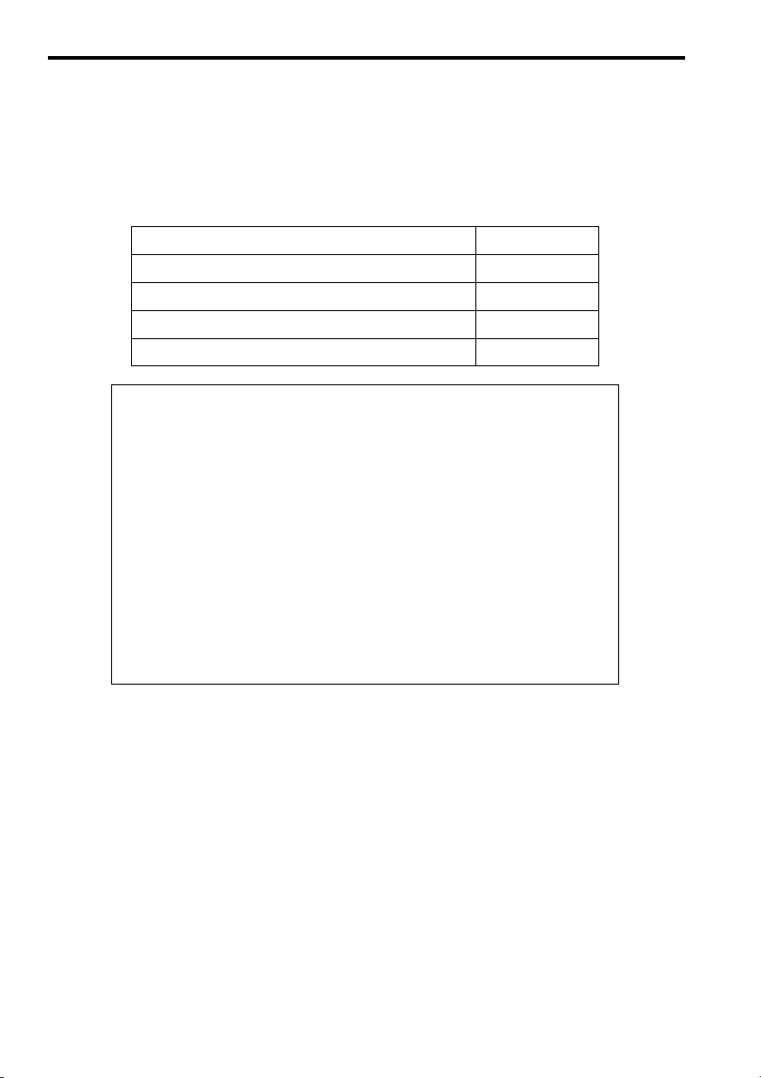
1 CHECKING ON DELIVERY
When Σ-Series products are delivered, check the following items:
Check Items
Check if the delivered products are the
ones you ordered.
Check if the motor shaft rotates smoothly.
Check for damage.
Check screws for looseness.
If any of the above items are faulty or incorrect, contact the dealer from which you purchased
the products or your nearest local sales representative.
Remarks
Checkthetypes marked on the nameplates of Servomotor and SERVOPACK (see the table on the next page).
Ifthemotor shaft is smoothly turned by hand,itis normal. However,
if the motor has brakes, it cannot be turned manually.
Checkthe overall appearance,and check fordamage or scratches resulting from transportation.
Check for looseness by using a screwdriver as necessary.
E-5
Page 10

1CHECKING ON DELIVERY
Servomotors
Appearance
Σ-Series
SGMM Servomotor
Nameplate
Rated output
Servomotor model
Serial number
Rated speed
Rated output
current
Manufacturing
date
Type
Standard Servomotors
SGMM
−A1
C
3
1
Σ Series
SGMM Servomotor
Rated output
10 W B3:3W
:
A1
20 W B5:5W
A2
:
30 W B9:10 W
A3
:
Power supply
C: 24 VDC
S: EN safety standards, 24 VDC
Encoder specifications
2048P/R incremental encoder
3:
F: 1024 P/R incremental encoder
Design revision order
Shaft specifications
Straight without key
2
:
3
Straight with flat seat
:
Option
C
With brake (24V)
:
Servomotors with Reduction Gears
SGMM
−A1
C
3
J
Σ Series
SGMM Servomotor
Rated output
10 W
:
A1
A2
20 W
:
30 W
A3
:
Power supply
C: 24 VDC
S: EN safety standards, 24 VDC
Encoder specifications
2048P/R incremental encoder
3:
With reduction gear
Deceleration rate
A: 1/5
B: 1/16
C: 1/25
Shaft specifications
Straight without key
2
:
Straight with flat seat
3
:
Option
C
With brake (24V)
:
2
j
1
2
j
SERVOPACKS
SGDFA1CS
DC24V
SERVOPACK
CN3
RDY
ALM
CN4
CN2/PG
CN1/IO
Σ-Series SGDF
SERVOPACK
C
N
5
SERVOPACK model
1.2
Serial number
Applicable
power supply
AC-OUTPUT
Applicable
motor capacity
SGDF
Σ Series
SGDF SERVOPACK
Rated output
10 W B3:3W
A1
:
A2
20 W B5:5W
:
A3
30 W B9:10 W
:
Power supply
C: 24 VDC
Type
S: Speed/torque control
P: Position control
− A1
C
S
E-6
Page 11

2 LIST OF STANDARD COMBINATION
W
A
to
Combination of SERVOPACK, Servomotor and Accessories
SERVOPACK
Type
SGDF-
10 W
20 W
30 W
3W
5W
10W
A1Cj
A2Cj
A3Cj
B3Cj
B3Cj
B3Cj
Applicable
Servomotor
SGMM-A1jj
SGMM-A2jj
SGMM-A3jj
SGMM-A3jj
SGMM-A3jj
SGMM-A3jj
* 1 Values at rated load.
* 2 Braking characteristics at 25
* 3 Yaskawa recommends noise filter manufactured by Tokin Corp. Contact Yaskawasales representa-
tive.
* 4 Power supply capacity required for maximum load.
Power Supply
Capacity per
SERVOPACK*
W
28
MCCB or
1
Capacity *
5
Fuse
A
42
60
22
24
30
°C : 200% for 2s or above, 700% for 0.01s
2
LF-205A
3 CABLE SPECIFICATIONS
The rated current and cable size of the SERVOPACK external terminals are shown in below.
Select cable specifications and size according to the operating environment and current capac-
ity.
SERVOPACK
Type
SGDF-
A1Cj
A2Cj
A3Cj
B3Cj
B5Cj
B9Cj
Main Circuit Power Input Terminal*
24VDC, GND,
Rated Current
(Arms)
1.2
Cable Spec.
(mm
0.5 min.
1.7
2.3
0.9
1.0
1.2
Recommended Noise
Type
Filter*
3
Spec.
Single-phase
200V, 5A
or above.
1
Motor Connection Terminals*
2
)
Rated Current
(Arms)
2.1
2.0
2.9
1.3
1.3
1.9
Magnetic
Contactor
HI-11J
(20A)or
equivalent
U, V, W,
2
*
Power
Supply
Capacity
to
SERVOPACK *
W
220
300
130
140
Cable Spec
2
)
(mm
4
1
* 1 The cable specifications are selected under conditions of three cables per bundle at 40°C ambient
temperature, with the rated current flowing.
* 2 Be sure to use Yaskawacables. For details, refer to 5.2 “Flowchart for Peripheral Device Selection”.
E-7
Page 12

4INSTALLATION
4 INSTALLATION
4.1 Transportation
4.2 Installing the Servomotor
J Installation direction
J Precautions for installation
J Installation sites:
D Do not lift or carry the Servomotor by the (encoder and/or motor) cables.
It may break the wire.
D Gently place the Servomotor when installing.
AC Servomotor can be installed either horizontally or vertically.
This is a precision equipment, therefore, avoid impacts
on motor or output shaft.
The Servomotor is designed for indoor use. Install Servomotor in an environment which meets
the following conditions:
D Free from corrosive and explosive gases
D Well-ventilated and free from dust and moisture
D Ambient temperature of 0 to 40°C
D Relative humidity of 20% to 80% (non-condensing)
D Inspection and cleaning can be performed easily
E-8
Page 13

Installing the SERVOPACK
3
4.
J Installation direction
D Mount the unit vertically on wall using the mounting holes on the baseplate, with main ter-
minals at the bottom.
D Since SERVOPACK is a self-cooling unit, supply enough space for cooling.
D If SERVOPACKS are mounted side by side, temperature may rise because of the uneven
temperature inside the panel. Therefore, provide a fan/fans above the SERVOPACK blow-
ing down on the units.
4.3 Installing the SERVOPACK
Fan 50 mm or more
30 mm
10 mm
or more
or more
J Installation sites:
Situation
When installed in a control panel
When installed near a heating unit
When installed near a source of vibration
Wheninstalled in aplacereceiving corrosive gases
Others
Fan
50 mm or more
Notes on Installation
Design the control panel size, unit layout, and cooling method so
that the temperature around the periphery of the SERVOPACK
does not exceed 50
Suppress radiation heat from the heating unit and a temperature
rise caused by convection so that the temperature around the periphery of the SERVOPACK does not exceed 50°C.
Install a vibration isolator underneath the SERVOPACK to prevent it from receiving vibration.
Corrosive gases do not immediately affect the SERVOPACK but
will eventually cause contactor-related devices to malfunction.
Take appropriate action to prevent corrosive gases.
Avoidinstallation inahot and humid place orwhereexcessive dust
or iron powder is present in the air.
°C.
40°C or below is preferable to maintain the reliability over a long period.
E-9
Page 14

5WIRING
5 WIRING
5.1 Typical Configuration
Before wiring, turn OFF the power ON/OFF switch and post a notice of“No Conduction.” Only an
electrical expert can perform the wiring.
E-10
Page 15

5.1 Typical Configuration
Molded-case circuit
breaker (MCCB)
Used to protect
power supply line.
Shuts the circuit
OFF when
overcurrent is
detected.
Noise filter
Used to eliminate external
noise from power supply line.
Magnetic contactor
Turns the Servo
ON or OFF.
Use a surge
suppressor for
the magnetic
contactor.
Model:
HI-Series
Molded-case
circuit breaker
Noise
filter
Power supply:
Single-phase
200 or 100 VAC
Host controller
The SGDF Servopack can be
used with most host controllers.
MEMOCON GL120/GL130 PLC
with Motion Control Module
Digital Operator
Personal computer
Connecting cable: JZSP-CFS01 to 03
Encoder cable
Allows the user to
set user constants
or operation
references and
display operation
status or alarm
status. Personal
computers can also
be used.
JUSP-OP02A-3
AC/DC power supply
Supplies Servopack
with 24 VDC.
Magnetic
contactor
AC/DC
power
supply
Power supply
ground line
Motor cable
E-11
Page 16

5WIRING
5.2 Flowchart for Peripheral Device Selection
Peripheral Device Selection Flowchart
Start peripheral device
selection
1) Select motor cables
SGMM-AjC/
SGMM-BjC
SGMM-AjC
Without brake/
With brake?
Without brake
With connector at
both ends/Cable only?
With connector at both ends
Select one of the following
according to cable length.
1m
→ JZSP-CFM00-01
3m→ JZSP-CFM00-03
5m→ JZSP-CFM00-05
SGMM-BjC
Select one of the following
according to cable length.
1m→ JZSP-CFM09-01
3m→ JZSP-CFM09-03
5m→ JZSP-CFM09-05
Select connector kit.
Servo side:
JZSP-CFM9-1
Motor side:
JZSP-CFM9-2
With connector at
both ends/Cable only?
Select one of the following
according to cable length.
1m→ JZSP-CFM01-01
3m→ JZSP-CFM01-03
5m→ JZSP-CFM01-05
With brake
With connector at
both ends/Cable only?
Cable only
Select one of the following
according to cable length.
1m→ JZSP-CFM10-01
3m→ JZSP-CFM10-03
5m→ JZSP-CFM10-05
With connector at both ends Cable only
Select one of the following
according to cable length.
1m→ JZSP-CFM09-01
3m→ JZSP-CFM09-03
5m→ JZSP-CFM09-05
With connector at both ends
Cable only
Select one of the following
according to cable length.
1m→ JZSP-CFM19-01
3m→ JZSP-CFM19-03
5m→ JZSP-CFM19-05
Select connector kit.
Servo side:
JZSP-CFM9-1
Motor side:
JZSP-CFM9-3
E-12
Select connector kit.
Servo side:
JZSP-CFM9-1
Motor side:
JZSP-CFM9-4
Page 17

2) Select encoder cable
SGMM-AjC
Select one of the following
according to cable length.
JZSP-CFP00-01
1m
3m
JZSP-CFP00-03
5m
JZSP-CFP00-05
Connector
at both ends
SGMM-AjC/
SGMM-BjC
SGMM-BjC
Select one of the following
according to cable length.
1m
3m
5m
Connector
at both
ends
JZSP-CFP01-01
JZSP-CFP01-03
JZSP-CFP01-05
Standard
Specifications/
European
Specifications
Standard
Specifications
Servopack
end with
connector
Servopack end
with connector
Select one of the following
according to cable length.
1m
3m
5m
5.2 Flowchart for Peripheral Device Selection
Select according to details provided
in 8.5 Encoder Cables.
Cable
//
only
Cable only
Select one of the following
according to cable length.
JZSP-CFP09-01
JZSP-VFP10-01
JZSP-VFP10-03
JZSP-VFP10-05
1m
3m
5m
JZSP-CFP09-03
JZSP-CFP09-05
EN
standard
Select connector kit
for motor side.
SGMM-AjC:
JZSP-CFP9-1
SGMM-BjC:
JZSP-CFP9-2
E-13
Select connector kit.
¯ Servopack side
JZSP-VFP9
¯ Motor side
SGMM-AjC:
JZSP-CFP9-1
SGMM-BjC:
JZSP-CFP9-2
Page 18

5WIRING
3) Select CN1 connector for
reference input.
Connector kit /
One cable end without connector
Connector kit One cable end
Connector kit
JZSP-VFP9
4) Select connector kit for power
supply:
5) Select SERVOPACK power supply
Power supply: 220 W min.
6) Select power supply circuit
breaker (MCCB) and noise filter
Capacity: 3 A
7) Use a magnetic contactor and
surge suppressor
JZSP-CFG9
End peripheral device selection
without connector
Cable with CN1
connector and one end
without connector
1m
JZSP-VFI01-01
3m
JZSP-VFI01-03
E-14
Page 19

5.3 Wiring Precautions
J Grounding wire
D In conformance with local electrical codes, ground the SERVOPACK’ s grounding terminal
.
D Be sure to connect the grounding wire of the Servomotor to
D Never share the grounding cable or grounding rod with welders, power equipment, or other
high-voltage devices. Separate the grounding cable from wiring of high-voltage equip-
ments.
D Make the grounding wire as short as possible. As for cable size, see Par. 3.
D If two or more SERVOPACKS are used, ground them as shown in (a) below.
Avoid methods (b) and (c).
5.3 Wiring Precautions
of the SERVOPACK.
GOOD
(a)
POOR
(b)
POOR
(c)
J Power supply
D Supply 24VDC for power supply.
D Do not connect three-phase power to output terminals U V W.Failure to observe this caution
may damage the SERVOPACK.
D Take care to prevent power line wiring or output wiring from touching or being enclosed
inside the case.
J Noise control
D If the speed signal line is affected by noise, malfunction may result.
• Separate power cables from control cables.
• Make the speed signal line as short as possible and use twisted-pair wires.
D Never use a noise filter (for power input) for motor circuit. If peripheral devices malfunc-
tion due to the noise from SERVOPACK, insert a noise filter (for output, type LF-310KA,
made by Tokin Corp.) between motor and SERVOPACK.
E-15
Page 20

6OPERATION
6 OPERATION
J Conducting test run for Servomotor without load
When Servomotor is operated without load, set the speed loop gain (user constant Cn-04) to
40 or less. (Factory setting is 80)
Speed loop gain(user constant Cn-04) is determined by the following conditions:
Load inertia ≥motor inertia ×3
Therefore, when motor is rotated without load (without load inertia) or load inertia is small,
if the value has been kept at the factory setting, the motor may oscillate.
To avoid this, make sure to set the value of Cn-04 (speed loop gain) to 40 or less and then servo
ON.
J Conducting test run with Servomotor connected to machine
SERVOPACK initial user constants setting is performed supposing the normal operation
conditions.
Before test run, set up user constants suitable for the machine.
Failure to set up the user constants initial setting may result in machine overrun or breakdown.
As for the setting procedures and methods, refer to “Digital Operator Operation
Manual.”
J Check items during test run
The following items should be checked during the test run.
D Unusual vibration
D Abnormal noise
D Excessive temperature rise
E-16
Page 21
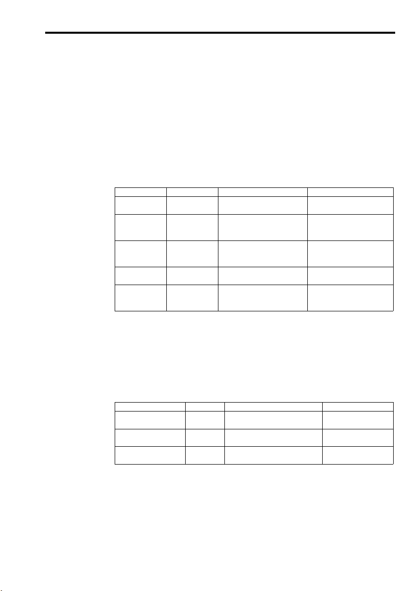
7 INSPECTION AND MAINTENANCE
7.1 Servomotor
For inspection and maintenance of Servomotors, follow the simple, daily inspection procedures in
the table below.
The AC Servomotors are brushless. Simple, daily inspection is sufficient. The inspection and main-
tenance frequencies in the table are only guidelines. Increase or decrease the frequency to suit the
operating conditions and environment.
7.1 Servomotor
Item
Vibration and
noise
Appearance
Insulation resistance measurement
Replace oil seal
Overhaul
* Measure across the Servomotor FG (Green/Yellow) and the U-phase (Red), V-phase (White), or
W-phase (Blue) power lead.
7.2 SERVOPACK
The SERVOPACK contains highly reliable parts and daily inspection is not required. Carry out the
inspections and maintenance in the table below once every year.
Item
Clean unit interior and circuit boards
Loose screws
Defective parts in unit or
on circuit boards.
Frequency
Daily
According to degree of contamination
At least once a
year
At least once every 5,000 hours
At least once every 20,000 hours
or 5 years
Frequency
At least once
a year
At least once
a year
At least once
a year
Procedure
Touch and listen.
Clean with cloth or compressed
air.
Disconnect SERVOPACK and
test insulation resistance at 500 V.
Must exceed 10 MΩ.*
Remove servomotor from machine and replace oil seal.
Contact your YASKAWA representative.
Procedure
Check for dust, dirt, and oil on the surfaces.
Check for loose terminal block and
connector screws.
Check for discoloration, damage or
discontinuities due to heating.
Comments
Levels higher than normal?
Contact your YASKAWA representative if the insulation resistance is below 10 MΩ.
Applies only to motors with oil
seal.
The customer should not disassemble and clean the Servomotor.
Remedy
Cleanwith compressedair.
Tighten any loose screws.
Contact your YASKAWA
representative.
E-17
Page 22

7INSPECTION AND MAINTENANCE
J Part replacement schedule
The following parts are subject to mechanical wear or deterioration over time. To avoid failure,
replace these parts at the frequency indicated.
Part
Smoothing Capacitor
Relays
Fuse
Electrolytic Capacitor on
Circuit Board
Note: Operating Conditions:
Ambient Temperature: annual average 30
Load Factor: 80% max.
Operation Rate: 20 hours/day max.
Standard Replacement
Period
7 to 8 years
---
10 years
5 years
°C
Replacement Method
Test. Replace with new part if necessary.
Test. Replace if necessary.
Replace with new part.
Test. Replace with new part if necessary.
E-18
Page 23

8.1 Applicable Servomotors
8 MEASURES TO SATISFY THE EMC DIRECTIVE
This section describes the measures required for SERVOPACKS to conform to EMC Directive
(EN55011, EN50082-2).
8.1 Applicable Servomotors
Use a Yaskawa Servomotor conforming to EN standards.
D Servomotor Models: SGMM-A1S312 (10 W)
SGMM-A2S312 (20 W)
SGMM-A3S312 (30 W)
8.2 Applicable Noise Filter
Use the following noise filter.
Make sure to ground the noise filter properly.
Model
Manufacturer
8.3 Applicable Power Supply
Use a power supply conforming to EN standards.
Make sure to ground the power supply properly.
Recommended power supply is as follows:
Model
Manufacturer
8.4 Motor Cables
The maximum cable length is 5 m (16.7 feet).
MYB-1206-33
NEMIC-LAMBDA K.K
PLEY24HSZ-PU
ETA ELECTRIC IND. Co., Ltd
E-19
Page 24

8MEASURES TO SATISFY THE EMC DIRECTIVE
8.5 Encoder Cables
Use an encoder cable with connector at both ends.
The maximum cable length is 5 m (16.7 feet). Select one of the following according to
cable length.
1 m: JZSP-VFP00-01
3 m: JZSP-VFP00-03
5 m: JZSP-VFP00-05
8.6 Control I/O
Use cables with CN1 connectors for control I/O. When using connector kits, use shielded
cable for the CN1 cable and make sure to ground between the cable shield and connector
case. Connect the shield at the host controller properly.
8.7 Digital Operator and Monitoring by Personal Computer
Use the Digital Operator or personal computer (for monitoring) for trial operation only.
Disconnect them during normal operation.
8.8 Cable Core
Model
Manufacturer
ESD-SR-25
Tokin Corp.
The cable line and line position where the core is attached is as follows:
Cable Line
Line Position
Encoder Line
Servopack end
Motor end
E-20
Servopack end
Motor Line
Page 25

8.9 Wiring Examples
The following diagram shows the wiring conditions conforming to EMC Directive. The
noise filter and the core are shown in the diagram.
8.9 Wiring Examples
Earth Plate/Shield Box
Power Supply
200 VAC
Single-phase
FG
2 m (78.7 in)
Power Supply
Noise
Filter
Clamp
Clamps: Fix and ground the cable shield using a piece of conductive metal.
AC/DC
Output: 24 VDC
Symbol
1
2
3
4
5
Controller cable
Motor cable
Encoder cable
AC Line cable
DC Line cable
SERVOPACK
24 VDC
, GND
FG
Name
SGDF-
CN1
Clamp
Controller
U, V, W
CN2
Core
ClampClamp
Core
Core
5 m (196.8 in)
Specification
Shield cable (0.5 m) (19.6 in)
Shield cable (5 m) (196.8 in)
Shield cable (5 m) (196.8 in)
Shield cable (2 m) (78.7 in)
Shield cable (0.5 m) (19.6 in)
Servomotor
SGMN-
Motor
Encoder
E-21
Page 26

AC Servo Drive Conforming to EN Standard
Σ-mini Series
INSTRUCTIONS
IRUMA BUSINESS CENTER (SOLUTION CENTER)
480, Kamifujisawa, Iruma, Saitama 358-8555, Japan
Phone 81-4-2962-5151 Fax 81-4-2962-6138
http://www.yaskawa.co.jp
YASKAWA AMERICA, INC.
2121 Norman Drive South, Waukegan, IL 60085, U.S.A.
Phone 1-800-YASKAWA (927-5292) or 1-847-887-7000 Fax 1-847-887-7310
http://www.yaskawa.com
YASKAWA ELÉTRICO DO BRASIL LTDA.
Avenida Piraporinha 777, Diadema, São Paulo, 09950-000, Brasil
Phone 55-11-3585-1100 Fax 55-11-3585-1187
http://www.yaskawa.com.br
YASKAWA EUROPE GmbH
Hauptstraβe 185, Eschborn 65760, Germany
Phone 49-6196-569-300 Fax 49-6196-569-398
http://www.yaskawa.eu.com
YASKAWA ELECTRIC KOREA CORPORATION
9F, Kyobo Securities Bldg. 26-4, Yeouido-dong, Yeongdeungpo-gu, Seoul, 150-737, Korea
Phone 82-2-784-7844 Fax 82-2-784-8495
http://www.yaskawa.co.kr
YASKAWA ELECTRIC (SINGAPORE) PTE. LTD.
151 Lorong Chuan, #04-02A, New Tech Park 556741, Singapore
Phone 65-6282-3003 Fax 65-6289-3003
http://www.yaskawa.com.sg
YASKAWA ELECTRIC (CHINA) CO., LTD.
12F, Carlton Bld., No.21 HuangHe Road, HuangPu District, Shanghai 200003, China
Phone 86-21-5385-2200 Fax 86-21-5385-3299
http://www.yaskawa.com.cn
YASKAWA ELECTRIC (CHINA) CO., LTD. BEIJING OFFICE
Room 1011, Tower W3 Oriental Plaza, No.1 East Chang An Ave.,
Dong Cheng District, Beijing 100738, China
Phone 86-10-8518-4086 Fax 86-10-8518-4082
YASKAWA ELECTRIC TAIWAN CORPORATION
9F, 16, Nanking E. Rd., Sec. 3, Taipei 104, Taiwan
Phone 886-2-2502-5003 Fax 886-2-2505-1280
YASKAWA ELECTRIC CORPORATION
In the event that the end user of this product is to be the military and said product is to be employed in any weapons systems or the manufacture
thereof, the export will fall under the relevant regulations as stipulated in the Foreign Exchange and Foreign Trade Regulations. Therefore, be sure to
follow all procedures and submit all relevant documentation according to any and all rules, regulations and laws that may apply.
Specifications are subject to change without notice for ongoing product modifications and improvements.
© 1999-2014 YASKAWA ELECTRIC CORPORATION. All rights reserved.
MANUAL NO. TOB-S800-27B
Published in Japan February 2014 99-2
13-6-9
15
-0
 Loading...