

Page 1

ACサーボパック
Σ-IIIシリーズ
安全上のご注意
SGDS-A
形式:
SGDS-F
SGDS-B
製品を安全にお使い頂くために,本書を必ずお読みください。
また,本書をお手元に保管していただくとともに,最終的に本製品をご使用になる
ユーザー様のお手元に確実に届けられるよう,お取り計らい願います。
AC SERVOPACK
Σ-III Series
SAFETY PRECAUTIONS
Model: SGDS-A
SGDS-F
SGDS-B
To properly use the product, read this manual thoroughly and retain
for easy reference, inspection, and maintenance. Ensure the end user
receives this manual.
MANUAL NO. TOBP S800000 00J
Page 2

Copyright © 2004
本書の内容の一部または全部を,当社の文書による許可なしに,転載または複製する
ことは,固くお断りします。
All rights reserved. No part of this publication may be reproduced, stored in a retrieval system,
or transmitted, in any form, or by any means, mechanical, electronic, photocopying, recording,
or otherwise, without the prior written permission of Yaskawa. No patent liability is assumed
with respect to the use of the information contained herein. Moreover, because Yaskawa is
constantly striving to improve its high-quality products, the information contained in this
manual is subject to change without notice. Every precaution has been taken in the preparation
of this manual. Nevertheless, Yaskawa assumes no responsibility for errors or omissions.
Neither is any liability assumed for damages resulting from the use of the information contained
in this publication.
株式会社 安川電機
YASKAWA ELECTRIC CORPORATION
Page 3
1 Introduction
This safety precautions manual covers Σ-III series SERVOPACK controlling Σ-III series AC
servomotor. To properly use the Σ-III series SERVOPACK, read this safety precautions manual
and user’s manual (see the following table) thoroughly, and retain for easy reference for inspections and maintenance, and so on. Make sure that these manuals reach the end user.
2 Reference Manuals
This table lists related reference manuals:
Σ-III Series SGMS/SGDS User’s Manual SIEPS80000000
Σ-III Series SGMS/SGDS Digital Operator INSTRUCTIONS TOBPS80000001
Σ-III Series SGMS/SGDS User’s Manual
For DeviceNet communications
Σ-III Series SGMS/SGDS User’s Manual
For MECHATROLINK-II communications
Linear Σ Series SGL/SGDS User’s Manual SIEPS80000016
3 General Precautions
The following describes general precautions. Note the following to ensure safe application.
• The drawings presented in this manual are sometimes shown without covers or protec-
tive guards. Always replace the cover or protective guard as specified first, and then
operate the products in accordance with the manual.
• The drawings presented in this manual are typical examples and may not match the
product you received.
• This manual is subject to change due to product improvement, specification modifica-
tion, and manual improvement. When this manual is revised, the manual code is
updated and the new manual is published as a next edition. The edition number appears
on the front and back covers.
• If the manual must be ordered due to loss or damage, inform your nearest Yaskawa rep-
resentative or one of the offices listed on the back of this manual.
• Yaskawa will not take responsibility for the results of unauthorized modifications of this
product. Yaskawa shall not be liable for any damages or troubles resulting from unau-
thorized modification.
1 Introduction
Manual Titles Manual No.
SIEPS80000002
SIEPS80000011
E-1
Page 4

4 Safety Information
WARNING
CAUTION
PROHIBITED
MANDATORY
The following conventions are used to indicate precautions in this manual. Failure to heed pre-
cautions provided in this manual can result in serious or possibly even fatal injury or damage to
the products or to related equipment and systems.
Indicates precautions that, if not heeded, could possibly result in loss of life or serious
injury.
Indicates precautions that, if not heeded, could result in relatively serious or minor injury,
damage to the product, or faulty operation.
In some situations, the precautions indicated could have series consequences if not heeded.
Indicates prohibited actions that must not be performed. For example, this symbol would
be used to indicate that fire is prohibited as follows: .
Indicates compulsory actions that must be performed. For example, this symbol
would be used as follows to indicate that grounding is compulsory: .
E-2
Page 5

5 Notes for Safe Operation
WARNING
Read this manual thoroughly before checking products on delivery, storage and transportation,
installation, wiring, operation and inspection, and disposal of the AC servo drives.
• Never touch any rotating motor parts while the motor is running.
Failure to observe this warning may result in injury.
• Before starting operation with a machine connected, make sure that an emergency stop can be
applied at any time.
Failure to observe this warning may result in injury.
• Never touch the inside of the SERVOPACKs.
Failure to observe this warning may result in electric shock.
• Do not remove the panel cover while the power is ON.
Failure to observe this warning may result in electric shock.
• Do not touch terminals for five minutes after the power is turned OFF.
Residual voltage may cause electric shock.
• Do not touch terminals for five minutes after voltage resistance test.
Residual voltage may cause electric shock.
• Follow the procedures and instructions for trial operation precisely as noted in the Σ-ΙΙΙ series User’s
Manual (Manual No.: SIEPS80000000A).
• Follow the procedures and instructions for the trial operation as noted in the applicable manual for
that product.
Malfunctions that occur after the servomotor is connected to the equipment not only damage the equipment,
but may also cause an accident resulting in death or injury.
• The output range of multi-turn data for Σ-ΙΙΙ series absolute detection system differs from that for con-
ventional systems (15-bit encoder and 12-bit encoder). Especially when “Infinite length positioning
system” of conventional type is to be configured with Σ-ΙΙΙ series, be sure to make the system modi-
fication.
• The multi-turn limit value must be changed only for special applications.
Changing it inappropriately or unintentionally can be dangerous.
• If the Multi-turn Limit Disagreement alarm occurs, check the setting of parameter Pn205 in the SER-
VOPACK to be sure that it is correct.
If Fn013 is executed when an incorrect value is set in Pn205, an incorrect value will be set in the encoder. The
alarm will disappear even if an incorrect value is set, but incorrect positions will be detected, resulting in a dangerous situation where the machine will move to unexpected positions.
5 Notes for Safe Operation
E-3
Page 6
• Do not remove the front cover, cables, connectors, or optional items while the power is ON.
WARNING
CAUTION
Failure to observe this warning may result in electric shock.
• Do not damage, press, exert excessive force or place heavy objects on the cables.
Failure to observe this warning may result in electric shock, stopping operation of the product, or burning.
• Do not modify the product.
Failure to observe this warning may result in injury or damage to the product.
• Provide an appropriate stopping device on the machine side to ensure safety. A holding brake for a
servomotor with brake is not a stopping device for ensuring safety.
Failure to observe this warning may result in injury.
• Do not come close to the machine immediately after resetting momentary power loss to avoid an
unexpected restart. Take appropriate measures to ensure safety against an unexpected restart.
Failure to observe this warning may result in injury.
• Connect the ground terminal to electrical codes (ground resistance: 100 Ω or less).
Improper grounding may result in electric shock or fire.
• Installation, disassembly, or repair must be performed only by authorized personnel.
Failure to observe this warning may result in electric shock or injury.
Checking on Delivery
• Always use the servomotor and SERVOPACK in one of the specified combinations.
Failure to observe this caution so may result in fire or malfunction.
E-4
Page 7

5 Notes for Safe Operation
CAUTION
CAUTION
Storage and Transportation
• Do not store or install the product in the following places.
• Locations subject to direct sunlight.
• Locations subject to temperatures outside the range specified in the storage/installation temperature conditions.
• Locations subject to humidity outside the range specified in the storage/installation humidity conditions.
• Locations subject to condensation as the result of extreme changes in temperature.
• Locations subject to corrosive or flammable gases.
• Locations subject to dust, salts, or iron dust.
• Locations subject to exposure to water, oil, or chemicals.
• Locations subject to shock or vibration.
Failure to observe this caution may result in fire, electric shock, or damage to the product.
• Do not hold the product by the cables or motor shaft while transporting it.
Failure to observe this caution may result in injury or malfunction.
• Do not place any load exceeding the limit specified on the packing box.
Failure to observe this caution may result in injury or malfunction.
• If disinfectants or insecticides must be used to treat packing materials such as wooden frames, pallets, or
plywood, the packing materials must be treated before the product is packaged, and methods other than
fumigation must be used.
Example: Heat treatment, where materials are kiln-dried to a core temperature of 56°C for 30
minutes or more.
If the electronic products, which include stand-alone products and products installed in machines, are packed with
fumigated wooden materials, the electrical components may be greatly damaged by the gases or fumes resulting from
the fumigation process. In particular, disinfectants containing halogen, which includes chlorine, fluorine, bromine, or
iodine can contribute to the erosion of the capacitors.
Installation
• Never use the products in an environment subject to water, corrosive gases, inflammable gases, or com-
bustibles.
Failure to observe this caution may result in electric shock or fire.
• Do not step on or place a heavy object on the product.
Failure to observe this caution may result in injury.
• Do not cover the inlet or outlet ports and prevent any foreign objects from entering the product.
Failure to observe this caution may cause internal elements to deteriorate resulting in malfunction or fire.
• Be sure to install the product in the correct direction.
Failure to observe this caution may result in malfunction.
• Provide the specified clearances between the SERVOPACK and the control panel or with other devices.
Failure to observe this caution may result in fire or malfunction.
• Do not apply any strong impact.
Failure to observe this caution may result in malfunction.
E-5
Page 8
Wiring
CAUTION
• Do not connect a three-phase power supply to the U, V, or W output terminals.
Failure to observe this caution may result in injury or fire.
• Securely connect the power supply terminal screws and motor output terminal screws.
Failure to observe this caution may result in fire.
• Do not bundle or run power and signal lines together in the same duct. Keep power and signal lines sepa-
rated by at least 30 cm (11.81 in).
• Use twisted-pair shielded wires or multi-core twisted pair shielded wires for signal and encoder (PG) feed-
back lines.
The maximum length is 3 m (118.11 in) for reference input lines and is 20 m (787.40 in) for PG feedback lines.
• Do not touch the power terminals for 5 minutes after turning power OFF because high voltage may still
remain in the SERVOPACK.
Make sure the charge indicator is out first before starting an inspection.
• Avoid frequently turning power ON and OFF. Do not turn power ON or OFF more than once per minute.
Since the SERVOPACK has a capacitor in the power supply, a high charging current flows for 0.2 seconds when
power is turned ON. Frequently turning power ON and OFF causes main power devices like capacitors and fuses to
deteriorate, resulting in unexpected problems.
• Observe the following precautions when wiring main circuit terminal blocks.
• Remove the terminal block from the SERVOPACK prior to wiring.
• Insert only one wire per terminal on the terminal block.
• Make sure that the core wire is not electrically shorted to adjacent core wires.
• Do not connect the SERVOPACK for 100 V and 200 V directly to a voltage of 400 V.
The SERVOPACK will be destroyed.
• Install the battery at either the host controller or the battery unit of the encoder.
It is dangerous to install batteries at both simultane ously, because that sets up a loop circuit between the batteries.
• Be sure to wire correctly and securely.
Failure to observe this caution may result in motor overrun, injury, or malfunction.
• Always use the specified power supply voltage.
An incorrect voltage may result in burning.
• Take appropriate measures to ensure that the input power supply is supplied within the specified voltage
fluctuation range. Be particularly careful in places where the power supply is unstable.
An incorrect power supply may result in damage to the product.
• Install external breakers or other safety devices against short-circuiting in external wiring.
Failure to observe this caution may result in fire.
E-6
Page 9
5 Notes for Safe Operation
CAUTION
CAUTION
• Take appropriate and sufficient countermeasures for each when installing systems in the following loca-
tions.
• Locations subject to static electricity or other forms of noise.
• Locations subject to strong electromagnetic fields and magnetic fields.
• Locations subject to possible exposure to radioactivity.
• Locations close to power supplies.
Failure to observe this caution may result in damage to the product.
• Do not reverse the polarity of the battery when connecting it.
Failure to observe this caution may damage the battery or cause it to explode.
Operation
• Conduct trial operation on the servomotor alone with the motor shaft disconnected from machine to avoid
any unexpected accidents.
Failure to observe this caution may result in injury.
• Before starting operation with a machine connected, change the settings to match the parameters of the
machine.
Starting operation without matching the proper settings may cause the machine to run out of control or malfunction.
• Forward run prohibited (P-OT) and reverse run prohibited (N-OT) signals are not effective during JOG
mode operation using parameter Fn002 and zero point search mode using parameter Fn003.
• When using the servomotor for a vertical axis, install the safety devices to prevent workpieces to fall off due
to occurrence of alarm or overtravel. Set the servomotor so that it will stop in the zero clamp state at occur-
rence of overtravel.
Failure to observe this caution may cause workpieces to fall off due to overtravel.
• When not using the normal autotuning, set to the correct moment of inertia ratio.
Setting to an incorrect moment of inertia ratio may cause vibration.
• Do not touch the SERVOPACK heatsinks, regenerative resistor, or servomotor while power is ON or soon
after the power is turned OFF.
Failure to observe this caution may result in burns due to high temperatures.
• Do not make any extreme adjustments or setting changes of parameters.
Failure to observe this caution may result in injury due to unstable operation.
• When an alarm occurs, remove the cause, reset the alarm after confirming safety, and then resume opera-
tion.
Failure to observe this caution may result in injury.
• Do not use the servo brake of the servomotor for ordinary braking.
Failure to observe this caution may result in malfunction.
E-7
Page 10

Maintenance and Inspection
CAUTION
CAUTION
• Do not disassemble the SERVOPACK.
Failure to observe this caution may result in electric shock or injury.
• Do not attempt to change wiring while the power is ON.
Failure to observe this caution may result in electric shock or injury.
• When replacing the SERVOPACK, resume operation only after transferring the previous SERVOPACK
parameters to the new SERVOPACK.
Failure to observe this caution may result in damage to the product.
Disposal
• When disposing of the products, treat them as ordinary industrial waste.
E-8
Page 11
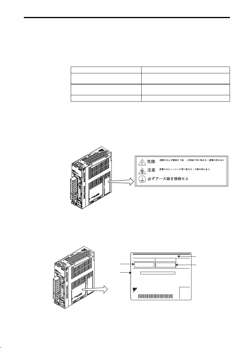
6 Checking Products on Delivery
Disconnect all power and wait 5 min.
before servicing. May cause electric shock.
Use proper grounding techniques.
CAUTION
WARNING
5
Do not touch heat sink when power is ON.
May cause burn.
SERVOPACK warning label
SERVOPACK type
SERVOPACK nameplate
Serial number
Applicable
power supply
Applicable
servomotor capacity
SGDS-02A01A
AC-OUTPUT
S/N
O/N
AC-INPUT
SERVOPACK
MODEL
YASKAWA ELECTRIC
MADE IN JAPAN
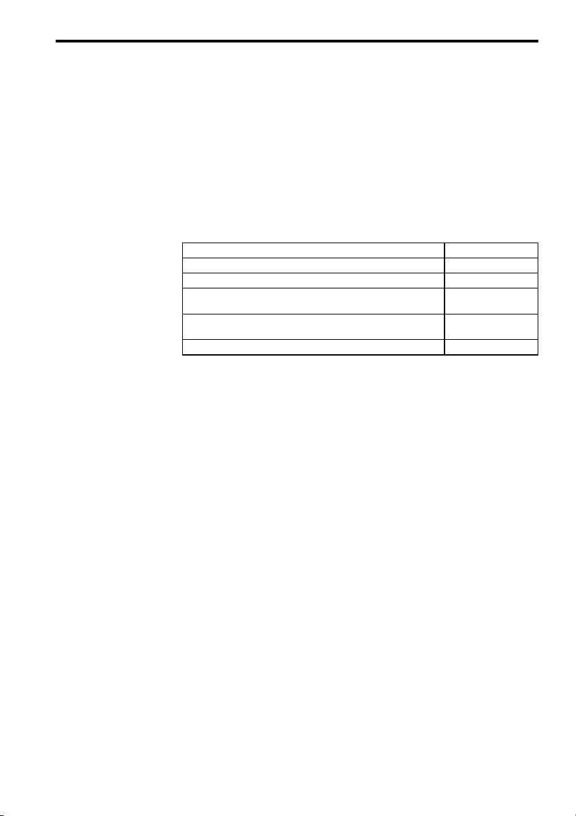
The following procedure is used to check Σ-ΙΙΙ Series products upon delivery. Check the follow-
ing items when Σ-ΙΙΙ Series products are delivered.
Check Items Comments
Are the delivered products the ones that
were ordered?
Is there any damage?
Are there any loose screws? Check screws for looseness using a screwdriver.
If any of the above items are faulty or incorrect, contact your Yaskawa sales representative or
the dealer from whom you purchased the products.
7 Warning Label
The following illustration shows the SERVOPACK warning label.
6 Checking Products on Delivery
Check the model numbers marked on the nameplates of
the SERVOPACK.
Check the overall appearance, and check for damage or
scratches that may have occurred during shipping.
8 Nameplate
The following illustration shows the SERVOPACK nameplate
E-9
.
Page 12
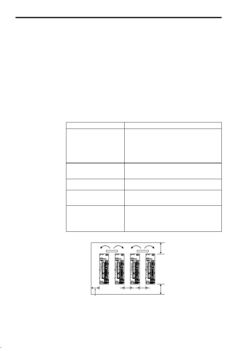
9 Installation
Cooling fan
Cooling fan
30 mm (1.2 in.) or more
10 mm (0.4 in.) or more
50 mm (2 in.) or more
50 mm (2 in.) or more
Observe the following precautions when installing SERVOPACK.
• Install SERVOPACK perpendicular to the wall so that the front panel (digital operator
mounted face) faces outward.
• Firmly secure the SERVOPACK through two or three mounting holes depending on the
SERVOPACK capacity.
• Install SERVOPACK so that SERVOPACK can be cooled by natural convection or fan.
Installation Sites
For installation sites, use proper care with the following notes.
Situation Notes on Installation
• Design the control panel size, unit layout, and cooling
method so that the temperature around the periphery of the
When installed in a control panel
When installed near a heating unit
When installed near a source of
vibration
When installed in a place receiving
corrosive gases
Others
SERVOPACK does not exceed 55°C.
• When installing multiple SERVOPACKs side by side in a
control panel, install cooling fans and provide sufficient
space around each SERVOPACK to allow cooling by fan
and natural convection.
Suppress radiation heat from the heating unit and a temperature rise caused by convection so that the temperature around
the periphery of the SERVOPACK does not exceed 55
Install a vibration isolator underneath the SERVOPACK to
prevent it from receiving vibration.
Corrosive gases do not immediately affect the SERVOPACK
but will eventually cause contactor-related devices to malfunction. Take appropriate action to protect against corrosive gases.
• Avoid installation in a hot and humid place or where excessive dust or iron powder is present in the air.
• Be sure there is no condensation or freezing.
• Keep the surrounding air temperature 45 °C or less to ensure
long-term reliability.
°C.
E-10
Page 13

10 Wiring
10.1 Molded-case Circuit Breaker and Fuse Capacity
10 Wiring
Main Circuit
Power Supply
Single-phase
100 V
Single-phase
200 V
Three-phase
200 V
* 1. Nominal value at the rated load. The specified derating is required to select an appropriate
* 2. Cutoff characteristics (25
Note: 1. Do not use a fast-acting fuse. Because the SERVOPACK’s power supply is a capacitor
SERVOPACK Model
Capacity
fuse capacity.
(kW)
0.03 A3B 0.25
0.05 A5F 0.25
0.10 01F 0.40
0.20 02F 0.60 6
0.40 04F 1.2 12
0.05 A5A 0.25
0.20 02A 0.75
0.40 04A 1.2 8
0.80 08A 2.2 16
0.45 05A 1.4 4
SGDS
1.0 10A 2.3 7
1.5 15A 3.2 10
2.0 20A 4.3 13
3.0 30A 5.9 17
5.0 50A 7.5 28
6.0 60A 12.5 32
7.5 75A 15.5 41
°C): 200% two seconds min. and 700% 0.01 seconds min.
input type, a fast-acting fuse may blow when the power is turned ON.
2. The SGDS SERVOPACK does not include a protective grounding circuit. Install a
ground-fault protector to protect the system against overload and short-circuit or protective grounding combined with the molded-case circuit breaker.
-
Power Supply
Capacity per
SERVOPACK
(kVA)
Current Capacity of the
Molded-case Circuit Breaker
and the Fuse
(A
)
rms
4
40.10 01A 0.40
∗1,∗
Rated Voltage
2
Fuse MCCB
250 V 240 V
10.2 Main Circuit Wiring
SGDS SERVOPACKs are suitable under the following conditions.
• With 100 V class: Less than 5000 Arms,120 V maximum.
• With 200 V class: Less than 5000 Arms, 240 V maximum.
SERVOPACKs must be used with UL-listed fuses or circuit breakers, in accordance with the
National Electrical Code (NEC).
Use 75 °C heat-resistant copper wires or an equivalent.
E-11
Page 14

10.3 SERVOPACK Main Circuit Wire Size
Cable Types
Cable Types
Symbol Name
PVC Normal vinyl cable
IV 600-V vinyl cable
HIV
Temperature-resistant
vinyl cable
Allowable Conductor
Temperature °C (°F)
−
60 (140)
75 (167)
• Wire sizes are selected for three cables per bundle at 40 °C (104 °F) surrounding air
temperature with the rated current.
• Use cable with a minimum withstand voltage of 600 V for main circuits.
• If cables are bundled in PVC or metal ducts, consider the reduction ratio of the allow-
able current.
• Use heat-resistant cables under high surrounding air or panel temperatures where
normal vinyl cables will rapidly deteriorate.
• Use cables within the allowable moment of inertia.
• Do not use cables under continuous regenerative state.
The following table shows the wire size and allowable current for three cables. Use a cable
whose specifications meet or are less than the values in the table.
• 600-V Heat-resistant Vinyl Cables (HIV)
Allowable Current at Surrounding Air
(86°F)
30°C
Temperature A
40°C
(104°F)
AWG Size
20
−
18
16
14
12
10
8 8.0 (0.0124)
6
4
Nominal
Section
Diameter
mm
(0.00078)
(0.00116)
(0.00140)
(0.00193)
(0.00310)
(0.00543)
(0.00853)
(0.0217)
(0.0341)
Note: The values in the table are only for reference.
Cross
2
(in2)
0.5
0.75
0.9
1.25
2.0
3.5
5.5
14.0
22.0
Configuration
Number of
wires/mm
2
)
(in
19/0.18
(0.00028)
30/0.18
(0.00028)
37/0.18
(0.00028)
50/0.18
(0.00028)
7/0.6
(0.00093)
7/0.8
(0.00124)
7/1.0
(0.00155)
7/1.2
(0.00186)
7/1.6
(0.00248)
7/2.0
(0.00310)
E-12
Conductive
Resistance
2
Ω/km
39.5 6.6 5.6 4.5
26.0 8.8 7.0 5.5
24.4 9.0 7.7 6.0
15.6 12.0 11.0 8.5
9.53 23 20 16
5.41 33 29 24
3.47 43 38 31
2.41 55 49 40
1.35 79 70 57
0.85 91 81 66
50°C
(122°F)
Page 15

10 Wiring
Main Circuit Power Supply Input Terminals (L1, L2, L3), Servomotor
Connection Terminals (U, V, W), Control Power Input Terminals (L1C,
L2C), External Regenerative Resistor Terminals (B1, B2)
Units: mm
Main
Circuit
Power
Supply
Single-
phase
100 V
Single-
phase
200 V
Threephase
200 V
Capacity
(kW)
0.03 A3B
0.05 A5F
0.1 01F
0.2 02F HIV2.0
0.05 A5A
0.1 01A
0.2 02A
0.4 04A
0.75 08A
0.45 05A
1.5 15A
2.0 20A
3.0 30A HIV5.5 HIV3.5
5.0 50A HIV5.5 HIV8.0 HIV5.5
6.0 60A HIV8.0
7.5 75A HIV14
SERVO-
PACK Model
SGDS- L1, L2, L3 U, V, W L1C, L2C B1, B2
HIV1.25
HIV1.25
HIV2.0
HIV2.0 HIV2.0
HIV3.5
Terminal Symbol
HIV1.25 HIV1.25 HIV1.25
HIV1.25 HIV1.25 HIV1.25
HIV3.5 HIV2.0
HIV14 HIV8.0
HIV1.25
HIV1.251.0 10A
2
Note: The wires for 0.03 kW to 1.5 kW SERVOPACKs need connectors for
wiring. The wires for 2.0 kW to 7.5 kW SERVOPACKs do not need
connectors for wiring.
E-13
Page 16

Ground Terminal
Main
Circuit
Power
Supply
Single-
phase
100 V
SERVOPACK
Capacity
(kW)
0.05 A5F
0.2 02F
Model
SGDS-
Wire Size
2
(mm
HIV2.0 or
more
Ground Terminal
Te rm i na l
Screw
)
Size
M4 1.2 to 1.40.1 01F
Tightening
Torque
(N
m)
0.05 A5A
Single-
phase
200 V
0.1 01A
0.2 02A
0.4 04A
HIV2.0 or
more
M4 1.2 to 1.4
0.75 08A
0.45 05A
1.0 10A
Three-
phase
200 V
1.5 15A
2.0 20A
3.0 30A
5.0 50A
6.0 60A
7.5 75A
HIV2.0 or
more
M4 1.2 to 1.4
M6 2.5 to 3.8
Signal Line Wire Sizes
Following table shows appropriate cables for CN1 and CN2 SERVOPACK connectors.
Wire sizes were selected for three cables per bundle at 40
with the rated current.
Connector Name and
Signal
Control I/O
Signal
Connector
PG Signal
Connector
CN1
CN2
Item Specification
Cable Use twisted-pair or shielded twisted-pair wire.
Applicable wire
Finished cable
dimension
Cable Use Yaskawa cable, or shielded twisted-pair
Applicable wire
Finished cable
dimension
°C surrounding air temperature
AWG24 (0.2 mm
2
), AWG26 (0.12 mm2),
AWG28 (0.08 mm2), AWG30 (0.05 mm2)
φ16.0 mm (φ0.63 in) MAX.
wire if Yaskawa cable is not used.
AWG24 (0.2 mm
AWG28 (0.08 mm
Use AWG22 (0.33 mm
supply and AWG26 (0.12 mm
nals. These conditions permit wiring distances
up to 20 m (65.6 ft).
2
), AWG26 (0.12 mm2),
2
), AWG30 (0.05 mm2)
2
) for the encoder power
2
) for other sig-
φ6.8 mm (φ0.27 in) MAX.
E-14
Page 17

10.4 Typical Main Circuit Wiring Examples
L1
L1C
SERVOPACK
SGDS-F
SGDS-A
U
V
∗1
∗2
W
M
PG
ALM−
0 V
24
1Ry
ALM+
1D
1KM
1Ry
1KM
1SA
1Ry
1KM
L2
B2
L2C
CN2
CN1
1QF
RT
1PL
FIL
+24V
1
2
B1/
Other
connectors
(For servo
alarm display)
Main circuit
power supply
ON
OFF
Main circuit
power supply
: Indicator lamp
: Surge absorber
: Flywheel diode
1PL
1SA
1D
1QF
FIL
1KM
1Ry
: Molded-case circuit breaker
: Noise filter
: Magnetic contactor
: Relay
Only qualified personnel should perform the wiring. Design the circuit so that the main cir-
cuit power supply turns OFF at emergency stop.
Single-phase, 100/200 V
* 1. These circuits are power lines, separated by the protecting separator.
Do not touch these terminals when the power is ON to avoid electric
shock.
* 2. These circuits are SELV circuits and are separated from all other cir-
cuits by double and reinforced insulation. The CN1 input signal is
available for sink or source circuits.
Note: Customers must purchase a 24-VDC power supply with a double-
shielded enclosure.
10 Wiring
E-15
Page 18

Three-phase 200 V
1SA
L1
L1C
PG
SERVOPACK
SGDS-A
U
V
W
M
0 V
24
1Ry
ALM+
ALM−
1D
1KM
1Ry
1KM
1Ry
1KM
L2
L3
B2
B3
L2C
CN1
CN2
1QF
RST
1PL
FIL
+24V
∗2
∗1
B1/
1
2
Other
connectors
(For servo
alarm display)
Main circuit
power supply
ON
OFF
Main circuit
power supply
: Indicator lamp
: Surge absorber
: Flywheel diode
1PL
1SA
1D
1QF
FIL
1KM
1Ry
: Molded-case circuit breaker
: Noise filter
: Magnetic contactor
: Relay
∗3
∗4
∗5
* 1. These circuits are power lines, separated by the protecting separator.
Do not touch these terminals when the power is ON to avoid electric
shock.
* 2. These circuits are SELV circuits and are separated from all other cir-
cuits by double and reinforced insulation. The CN1 input signal is
available for sink or source circuits.
* 3. A SERVOPACK with a capacity of 6.0 kW or more has both the B1
terminal and the terminal.
* 4. SERVOPACKs with a capacity of 6.0 kW or more do not have a B3
terminal.
* 5. SERVOPACKs with a capacity of 6.0 kW or more do not have termi-
nals 1 and 2. Use terminal instead.
Note: Customers must purchase a 24-VDC power supply with a double-
shielded enclosure.
E-16
Page 19

Single-phase 200 V, 800 W
1SA
L1
L1C
PG
SERVOPACK
SGDS-08A
U
V
W
M
0 V
24
1Ry
ALM+
ALM−
1D
1KM
1Ry
1KM
1Ry
1KM
L2
L3
L2C
CN1
CN2
1QF
RT
1PL
FIL
+24V
B2
B3
∗3
∗2
∗1
B1/
1
2
Other
connectors
(For servo
alarm display)
Main circuit
power supply
ON
OFF
Main circuit
power supply
: Indicator lamp
: Surge absorber
: Flywheel diode
1PL
1SA
1D
1QF
FIL
1KM
1Ry
: Molded-case circuit breaker
: Noise filter
: Magnetic contactor
: Relay
* 1. The L3 terminal is not used for single-phase 200 V, 800 W SERVO-
PACKs. Do not use this terminal.
* 2. These circuits are power lines, separated by the protecting separator.
Do not touch these terminals when the power is ON to avoid electric
shock.
* 3. These circuits are SELV circuits and are separated from all other cir-
cuits by double and reinforced insulation. The CN1 input signal is
available for sink or source circuits.
Note: Customers must purchase a 24-VDC power supply with a double-
shielded enclosure.
10 Wiring
E-17
Page 20

11 Inspection
This section describes the SERVOPACK basic inspections and part replacement period.
SERVOPACK Inspection
Exterior
Loose screws
SERVOPACK’s Parts Replacement Schedule
For inspections and maintenance of the SERVOPACK, follow the inspection procedures in
the table below at least once every year.
Item Frequency Procedure Remedy
At least once a year
Check for dust, dirt, and oil on
surfaces.
Check for loose terminal block
and connector screws.
Clean with compressed
air or cloth.
Tighten any loose
screws.
The following electric or electronic parts are subject to mechanical wear or deterioration
over time. To avoid failure, replace these parts at the frequency indicated.
Refer to the standard replacement period in the following table, contact your Yaskawa repre-
sentative. After an examination of the part in question, we will determine whether the parts
should be replaced or not.
The parameters of any SERVOPACKs overhauled by Yaskawa are reset to the factory set-
tings before shipping. Be sure to confirm that the parameters are properly set before starting
operation.
Part
Cooling Fan
Smoothing Capacitor
Relays
Fuses
Aluminum Electrolytic
Capacitor on Circuit Board
Standard
Replacement
Period
4 to 5 years
7 to 8 years
−
10 years
5 years
E-18
Operating Conditions
• Surrounding Air Temperature: Annual average
of 30°C
• Load Factor: 80% max.
• Operation Rate: 20 hours/day max.
Page 21

12 General Specifications
The following table shows the SERVOPACK general specifications.
Item Specifications
Operating/Storage Temperature 0 to +55 °C/-20 to +85 °C
Operating/Storage Humidity 90 %RH or less (non-condensing)
Operating Environment
Vibration Resistance
Shock Resistance
Voltage Resistance
Insulation Resistance
Overseas Standards
12 General Specifications
Installation category (Overvoltage category): III
Pollution degree: 2
Protection class: 10
Altitude: 1,000 m max.
2
4.9 m/s
2
19.6 m/s
Voltage: 1,500 V rms AC, for one minute
Braking current: 30 mA
Frequency: 50 Hz or 60 Hz
Voltage applied points: Between the frame ground and the
point where the terminals L1, L2, L3, L1C, L2C, U, V, and W
connect.
10 M
Ω min. (500 VDC megger) between the frame ground
and the power terminals U, V, and W
UL Standards: UL508C
EMC Directives: EN61000-6-2, EN55011 (group1 class A)
Low Voltage Directive: EN50178
E-19
Page 22

13 Installation Conditions of EMC Directive
To adapt a combination of a SGMS servomotor and a SGDS SERVOPACK to EMC Direc-
tives (EN55011 group1 classA, EN61000-6-2), the following conditions must be satisfied.
However, because this product is built-in, check that the following conditions are still met after
being installed in the final product.
13.1 EMC Installation Conditions
This section describes the installation conditions that satisfy EMC guidelines for each model
of the SGDS SERVOPACK. The conditions required for the standard type (base mounted)
of SERVOPACK are described. Refer to this section for other SERVOPACK models such
as the rack mounted types as well.
This section describes the EMC installation conditions satisfied in test conditions prepared
by Yaskawa. The actual EMC level may differ depending on the actual system’s configura-
tion, wiring, and other conditions.
E-20
Page 23

13 Installation Conditions of EMC Directive
Power supply
Single-phase 100 VAC
or 200 VAC
U, V, W
L1, L2
L1C, L2C
CN2
CN1
Ground plate
SERVOPACK
PE
PE
Encoder
Servo-
motor
Brake
1
2
3
4
Clamp
Noise
filter
Brake power supply
Core
Clamp
Clamp
Host controller
Surge
absorber
The cable must
be coiled once.
SGDS-0A (Analog, Pulse-train Interface)
Single-phase 100 V/200 V:
SGDS-A5F0A to -04F0A: Single-phase 100 VAC, 50 W to 400 W
SGDS-A5A0A to -08A0A: Single-phase 200 VAC, 50 W to 400 W and 800 W
SGDS-A3B0A: Single-phase 100 VAC, 30 W
Symbol Cable Name Specification
I/O signal cable Shield cable
c
Servomotor cable Shield cable
d
Encoder cable Shield cable
e
AC power supply cable Shield cable
f
E-21
Page 24

Three-phase 200 V:
U, V, W
L1, L2, L3
L1C, L2C
CN2
CN1
PE
PE
1
2
3
4
Ground plate
SERVOPACK
Clamp
Noise
filter
Brake power supply
Surge
absorber
Clamp
Clamp
Encoder
Servo-
motor
Brake
Host controller
Power supply
Three-phase 200 VAC
Core
The cable must
be coiled once.
SGDS-05A0A, -10A0A: Three-phase 200 VAC, 500 W, 1.0 kW
Symbol Cable Name Specification
I/O signal cable Shield cable
c
Servomotor cable Shield cable
d
Encoder cable Shield cable
e
AC Line cable Shield cable
f
E-22
Page 25

13 Installation Conditions of EMC Directive
U, V, W
L1, L2, L3
L1C, L2C
CN2
CN1
PE
PE
1
2
3
4
Ground plate
SERVOPACK
Clamp
Noise
filter
Brake power supply
Surge
absorber
Clamp
Clamp
Encoder
Servo-
motor
Brake
Host controller
Power supply
Three-phase 200 VAC
SGDS-15A0A to -50A0A: Three-phase 200 VAC, 1.5 kW to 5.0 kW
Symbol Cable Name Specification
I/O signal cable Shield cable
c
Servomotor cable Shield cable
d
Encoder cable Shield cable
e
AC Line cable Shield cable
f
E-23
Page 26

SGDS-60A0A to -75A0A: Three-phase 200 VAC, 6.0 kW to 7.5 kW
U, V, W
L1, L2, L3
L1C, L2C
CN2
CN1
PE
PE
1
2
3
4
Ground plate
SERVOPACK
Clamp
Noise
filter
Brake power supply
Surge
absorber
Clamp
Clamp
Encoder
Servo-
motor
Brake
Host controller
Power supply
Three-phase 200 VAC
Fan
6
Clamp
B1, B2
5
Regenerative
resistor
Symbol Cable Name Specification
I/O signal cable Shield cable
c
Servomotor cable Shield cable
d
Encoder cable Shield cable
e
AC Line cable Shield cable
f
Regenerative resistor cable Shield cable
g
Fan cable (only for SGMSS-70A) Shield cable
h
E-24
Page 27

13 Installation Conditions of EMC Directive
U, V, W
L1, L2
L1C, L2C
CN2
CN6
PE
PE
1
2
3
4
Core
Core
Core
Power supply
Single-phase 100 VAC
or Single-phase 200 VAC
SERVOPACK
Encoder
Servo-
motor
Brake
Noise
filter
Brake power supply
Surge
absorber
Ground plate
Core
Host controller
The cable must
be coiled once.
The cable must
be coiled twice.
The cable must
be coiled once.
SGDS-1A (MECHATROLINK-II Interface)
Single-phase 100 V/200 V:
SGDS-A5F1A to -04F1A: Single-phase 100 VAC, 50 W to 400 W
SGDS-A5A1A to -08A1A: Single-phase 200 VAC, 50 W to 400 W and 800 W
SGDS-A3B0A: Single-phase 100 VAC, 30 W
Symbol Cable Name Specification
Serial communication cable Shield cable
c
Servomotor cable Shield cable
d
Encoder cable Shield cable
e
AC Line cable Shield cable
f
E-25
Page 28

Three-phase 200 V:
U, V, W
L1, L2, L3
L1C, L2C
CN2
CN6
PE
PE
1
2
3
4
Ground plate
SERVOPACK
Clamp
Noise
filter
Brake power supply
Surge
absorber
Clamp
Clamp
Encoder
Servo-
motor
Brake
Host controller
Power supply
Three-phase 200 VAC
Core
The cable must
be coiled once.
SGDS-05A1A, -10A1A: Three-phase 200 VAC, 500 W, 1.0 kW
Symbol Cable Name Specification
I/O signal cable Shield cable
c
Servomotor cable Shield cable
d
Encoder cable Shield cable
e
AC Line cable Shield cable
f
E-26
Page 29

13 Installation Conditions of EMC Directive
U, V, W
L1, L2, L3
L1C, L2C
CN2
CN6
PE
PE
1
2
3
4
Clamp
ClampClamp
Power supply
Three-phase 200 VAC
SERVOPACK
Encoder
Servo-
motor
Brake
Noise
filter
Brake power supply
Surge
absorber
Ground plate
Core
Host controller
The cable must be
coiled four times.
SGDS-15A1A to -50A1A: Three-phase 200 VAC, 1.5 kW to 5.0 kW
Symbol Cable Name Specification
Serial communication cable Shield cable
c
Servomotor cable Shield cable
d
Encoder cable Shield cable
e
AC Line cable Shield cable
f
E-27
Page 30

SGDS-60A1A to -75A1A: Three-phase 200 VAC, 6.0 kW to 7.5 kW
Power supply
Three-phase 200 VAC
PE
Ground plate
Brake power supply
SERVOPACK
Noise
filter
Clamp
4
Surge
absorber
Regenerative
resistor
L1, L2, L3
L1C, L2C
B1, B2
5
U, V, W
CN1
Core
1
Host controller
CN2
The cable must be
coiled four times.
Symbol Cable Name Specification
I/O signal cable Shield cable
c
Servomotor cable Shield cable
d
Encoder cable Shield cable
e
AC Line cable Shield cable
f
Regenerative resistor cable Shield cable
g
Fan cable (only for SGMSS-70A) Shield cable
h
Clamp
ClampClamp
6
2
3
Fan
Brake
Servo-
motor
Encoder
PE
E-28
Page 31

13 Installation Conditions of EMC Directive
Cable
Ferrite core
Cable
Ferrite core
Host controller side
Ground plate
Cable
Cable
clamp
Shield (cable sheath stripped)
Fix and ground the cable shield
using a piece of conductive metal.
Remove paint on mounting surface.
Attaching the Ferrite Core
One turn Two turn
Recommended Ferrite Core
Cable Name Ferrite Core Model Manufacturer
Servomotor main circuit cable
ESD-SR-25 NEC TOKIN Corp.
Fixing the Cable
Fix and ground the cable shield using a piece of conductive metal.
• Example of Cable Clamp
Shield Box
A shield box, which is a closed metallic enclosure, should be used for shielding magnetic
interference. The structure of the box should allow the main body, door, and cooling unit to
be attached to the ground. The box opening should be as small as possible.
13.2 Hand-held Digital Operator and Analog Monitor Cable
Do not connect the hand-held digital operator and the analog monitor cable to the SERVO-
PACK during operations. Connect them only when the machinery is stopped during mainte-
nance.
E-29
Page 32

13.3 Peripheral Device Types and Capacities
Main
Circuit
Power
Supply
Singlephase
100 V
Singlephase
200 V
Threephase
200V
Model
Capacity
SGDS- Model Spec Fuse MCCB
(kW)
0.03 A3B 0.25 4
0.05 A5F 0.25 4
0.10 01F 0.40 4
0.20 02F 0.60 6
0.40 04F 1.2 8
0.05 A5A 0.25 4
0.10 01A 0.40
0.20 02A 0.75
0.40 04A 1.2 8
0.80 08A 2.2 16
0.50 05A 1.4 4
1.0 10A 2.3 7
1.5 15A 3.2 10
2.0 20A 4.3 13
3.0 30A 5.9 17
5.0 50A 7.5 28
6.0 60A 12.5 32
7.5 75A 15.5 41
* 1. This is the net value for a rated load.
When selecting fuse, determine the capacity using the prescribed derating.
Braking characteristics 25 °C: 200 % for 2s min.; 700 % for 0.01s min.
* 2. The FN-type noise filter is made by SCHAFFNER.
The FMAC-type noise filter is made by SCHURTER (previously TIMONTA).
* 3. The R.C.M type surge absorber is made by OKAYA ELECTRIC INDUSTRIES CO., LTD.
* 4. Made by YASKAWA Controls Co., Ltd.
Power
Supply
Capacity
per
SERVOPACK
(kVA)
MCCB
or Fuse
Capacity
(Arms)
Recommended Noise
∗1
FN2070
-6/07
FN2070
-10/07
FN2070
-6/07
FN2070
4
-6/07
FN2070
-10/07
FN2070
-16/07
FN258L
-7/07
FN258L
-16/07
FN258L
-30/07
FMAC
-0934
-5010
FMAC
-0953
-6410
∗2
Filter
Single-phase
250VAC, 6A
Single-phase
250VAC, 6A
Single-phase
250VAC, 6A
Single-phase
250VAC, 10A
Single-phase
250VAC, 10A
Single-phase
250VAC, 6A
Single-phase
250VAC, 6A
Single-phase
250VAC, 10A
Single-phase
250VAC, 16A
Three-phase
480VAC, 7A
Three-phase
480VAC, 16A
Three-phase
480VAC, 30A
Three-phase
480VAC, 50A
Three-phase
480VAC, 64A
Recommended
Surge
Absorber
∗3
R.C.M601BQZ-4
R.C.M601BQZ-4
R.C.M-
601BUZ-4
Magnetic
Contactor
∗4
HI-11J
(20A)
HI-11J
(20A)
HI-15J
(35A)
HI-11J
(20A)
HI-15J
(35A)
HI-20J
(35A)
HI-25J
(50A)
HI-35J
(6
5A)
Rated Voltage
250 V 240 V
Noise Filter for Brake Power Supply
Use an FN2070-6107 made by SCHAFFNER for a servomotor of 400 W or less.
E-30
Page 33

14 Installation Conditions of UL Standards
8.0
1.2
φ4.5
φ7.1
φ4.3
9.3
8.5
21.8
12.0
1.5
φ5.8
φ9.0
φ5.3
13.3
10.5
29.8
To adapt SERVOPACKs to UL Standards, use the following ring terminal kit for cables to con-
nect the motor output terminals U,V, and W.
SERVOPACK Model Terminals Terminal Kit Model
SGDS-50A
(5.0 kW)
U, V, W
(Motor output)
JZSP-CST9-50A
(Crimp terminals and Sleeves × 3 sets)
Dimensional Drawings
(Crimp terminal)
14 Installation Conditions of UL Standards
SGDS-60A
(6.0 kW)
SGDS-75A
(7.5 kW)
U, V, W
(Motor output)
JZSP-CST9-75A
(Crimp terminals and Sleeves × 3 sets)
Dimensional Drawings
(Crimp terminal)
E-31
Page 34

15 Overload Characteristics
The overload detection level is set under hot start* conditions at a servomotor surrounding air
temperature of 40°C (104°F).
10000.0
1000.0
Detecting time (s)
100.0
A
10.0
1.0
100%
B
C
* A hot start indicates that both the SERVOPACK and the servomotor have
run long enough at the rated load to be thermally saturated.
Note: The overload protection characteristics of A, B, and C in the figure
are applicable when the SERVOPACK is combined with one of the
following servomotors.
Graph
Type
SGMAS SGMPS SGMSS SGMCS SGMMJ SGMGH
-A5 to -04 -01 to -04 − -02 to -35 -A1 to -A3 −
A
-06 to -12 -08 to -15 -10 to -30 -45 to -2Z − -03 to -30
B
−−-40 to -70 −−-40 to -75
C
Motor Type
Maximum torque
Rated torque
Maximum torqueRated torque
(Maximum current)(Rated current)
× 100%
E-32
Page 35

Revision History
Date of
publication
Revision Number
Date of original
publication
MANUAL NO. TOBP S800000 00A
Published in Japan June 2002 02-3
00
20
19
18
17
1615141312
111098765
432
1
The revision dates and numbers of the revised manuals are given on the bottom of the back cover.
Date of
Publication
January 2014 Back cover Revision: Address
February 2013 Back cover Revision: Address
August 2012 Back cover Revision: Address
March 2012
November 2010
July 2010
August 2008
June 2008 Back cover Revision: Address
December 2007 Back cover Revision: Address
November 2007
July 2006 All chapters Addition: 6- kW and 7.5-kW SERVOPACKs
July 2005 Back cover Revision: Address
May 2005 All chapters Addition: Description of SGMGH servomotor
September 2004 14 Addition: Installation conditions of UL standards
September 2004 All chapters Addition: 5.0-kW SERVOPACK
August 2003 All chapters Addition: New models of SERVOPACKs and servomotors
June 2003 Back cover Revision: Address
March 2003 13 Addition: EMC Directive
October 2002 12 Revision: Installation category (overvoltage category)
June 2002 Back cover Revision: Address
March 2002
Rev.
Section Revised Content
No.
Inside of
back cover
Back cover Revision: Address
Front cover Revision: Format
Back cover Revision: Address, format
10.1, 13.3 Addition: Rated voltage
15 Addition: Current description
Back cover Revision: Address
12 Revision: Protection class 1X → 10
All chapters Revision: Ambient temperature → surrounding air temperature
5 Addition: PL on fumigation
All chapters Revision: Surge protector → surge absorber
Back cover Revision: Address
−
- First edition
Addition: Precautions for Korean Radio Waves Act
Page 36

AC SERVOPACK
Σ-III Series
SAFETY PRECAUTIONS
IRUMA BUSINESS CENTER (SOLUTION CENTER)
480, Kamifujisawa, Iruma, Saitama 358-8555, Japan
Phone 81-4-2962-5151 Fax 81-4-2962-6138
http://www.yaskawa.co.jp
YASKAWA AMERICA, INC.
2121 Norman Drive South, Waukegan, IL 60085, U.S.A.
Phone 1-800-YASKAWA (927-5292) or 1-847-887-7000 Fax 1-847-887-7310
http://www.yaskawa.com
YASKAWA ELÉTRICO DO BRASIL LTDA.
Avenida Piraporinha 777, Diadema, São Paulo, 09950-000, Brasil
Phone 55-11-3585-1100 Fax 55-11-3585-1187
http://www.yaskawa.com.br
YASKAWA EUROPE GmbH
Hauptstraβe 185, Eschborn 65760, Germany
Phone 49-6196-569-300 Fax 49-6196-569-398
http://www.yaskawa.eu.com
YASKAWA ELECTRIC KOREA CORPORATION
9F, Kyobo Securities Bldg. 26-4, Yeouido-dong, Yeongdeungpo-gu, Seoul, 150-737, Korea
Phone 82-2-784-7844 Fax 82-2-784-8495
http://www.yaskawa.co.kr
YASKAWA ELECTRIC (SINGAPORE) PTE. LTD.
151 Lorong Chuan, #04-02A, New Tech Park 556741, Singapore
Phone 65-6282-3003 Fax 65-6289-3003
http://www.yaskawa.com.sg
YASKAWA ELECTRIC (CHINA) CO., LTD.
12F, Carlton Bld., No.21 HuangHe Road, HuangPu District, Shanghai 200003, China
Phone 86-21-5385-2200 Fax 86-21-5385-3299
http://www.yaskawa.com.cn
YASKAWA ELECTRIC (CHINA) CO., LTD. BEIJING OFFICE
Room 1011, Tower W3 Oriental Plaza, No.1 East Chang An Ave.,
Dong Cheng District, Beijing 100738, China
Phone 86-10-8518-4086 Fax 86-10-8518-4082
YASKAWA ELECTRIC TAIWAN CORPORATION
9F, 16, Nanking E. Rd., Sec. 3, Taipei 104, Taiwan
Phone 886-2-2502-5003 Fax 886-2-2505-1280
YASKAWA ELECTRIC CORPORATION
In the event that the end user of this product is to be the military and said product is to be employed in any weapons systems or the manufacture
thereof, the export will fall under the relevant regulations as stipulated in the Foreign Exchange and Foreign Trade Regulations. Therefore, be sure to
follow all procedures and submit all relevant documentation according to any and all rules, regulations and laws that may apply.
Specifications are subject to change without notice for ongoing product modifications and improvements.
© 2002-2014 YASKAWA ELECTRIC CORPORATION. All rights reserved.
MANUAL NO. TOBP S800000 00J
Published in Japan January 2014 02-3
13-6-9
20
-0
Page 37

한국 전파법에 관한 주의사항
韓国電波法に関連する注意事項
Precautions for Korean Radio Waves Act
针对韩国电波法的注意事项
기종별 사용자 안내문
A급 기기
( 업무용 방송 통신기 자재 )
이 기기는 업무용 (A 급 ) 전자파 적합 기기로서 판매자
또는 , 사용자는 이 점을 주의하시기 바라며 , 가정외의
지역에서 사용하는 것을 목적으로 합니다 .
사용자 안내문
 Loading...