

Page 1

ACサーボパック
Σ-IIシリーズ
取扱説明書
MECHATROLINKインタフェースモジュール
形式:JUSP-NS100
対象サーボパック形式:SGDH-E-
製品を安全にお使い頂くために,本書を必ずお読みください。
また,本書をお手元に保管していただくとともに,最終的に本製品をご使用になる
ユーザー様のお手元に確実に届けられるよう,お取り計らい願います。
AC SERVOPACK
Σ-II Series
INSTRUCTIONS
MECHATROLINK Interface Module
Model: JUSP-NS100
Applicable SERVOPACK Model: SGDH-E-
To properly use the product, read this manual thoroughly and retain
for easy reference, inspection, and maintenance. Ensure the end user
receives this manual.
MANUAL NO. TOB-C718-4C
Page 2

Copyright © 2001
本書の内容の一部または全部を,当社の文書による許可なしに,転載または複製する
ことは,固くお断りします。
All rights reserved. No part of this publication may be reproduced, stored in a retrieval system,
or transmitted, in any form, or by any means, mechanical, electronic, photocopying, recording,
or otherwise, without the prior written permission of Yaskawa. No patent liability is assumed
with respect to the use of the information contained herein. Moreover, because Yaskawa is
constantly striving to improve its high-quality products, the information contained in this
manual is subject to change without notice. Every precaution has been taken in the preparation
of this manual. Nevertheless, Yaskawa assumes no responsibility for errors or omissions.
Neither is any liability assumed for damages resulting from the use of the information contained
in this publication.
株式会社 安川電機
YASKAWA ELECTRIC CORPORATION
Page 3

はじめに
■ 本書の構成
この取扱説明書は,日本語編と英語編で構成しています。
•
日本語編: J-1 ページ ~ J-25 ページに掲載
•
英語編: E-1 ページ ~ E-25 ページに掲載
必要に応じて,ご活用ください。
■ 本書の対象読者
本書は下記の方々を対象読者としています。
•
Σ-II シリーズ サーボパックの到着時の点検を行う方
•
Σ-II シリーズ サーボパックの盤組み込みや配線を行う方
•
Σ-II シリーズ サーボパックの操作や運転を行う方
•
Σ-II シリーズ サーボパックの保守や点検を行う方
INTRODUCTION
Manual Contents
■
This manual consists of Japanese Version and English Version.
• Japanese Version: Described on pages J-1 to J-25.
• English Version: Described on pages E-1 to E-25.
Use the Japanese Version or English Version as needed.
User Instructions
■
Use these instructions for the following jobs:
•
Checking Σ-II Series SERVOPACK on delivery
•
Installing Σ-II Series SERVOPACK
•
Wiring Σ-II Series SERVOPACK
•
Operating Σ-II Series SERVOPACK
•
Inspecting and maintenance of Σ-II Series SERVOPACK
iii
Page 4

CONTENTS
Σ-II Series
MECHATROLINK Interface Module - - - - - - - - - - - - - - E-1
SYMBOLS FOR SAFE OPERATION
NOTES FOR SAFE OPERATION
- - - - - - - - - - - - - - - - - - - - - - - E-4
- - - - - - - - - - - - - - - - - - - - - - - - - E-4
1
2
3
4
5
6
- - - - - - - - - - - - - - - - - - - - - - - - - - - - - - - - - - - - - - E-8
PAR TS
CHECKING ON DELIVERY
2.1
Checking Items
2.2
Appearance and Nameplate
2.3
Type Designation
2.4
Mounting NS100 Module
INSTALLATION
3.1
Storage
3.2
Installation Sites
3.3
Orientation
3.4
Installation Precations
WIRING
4.1
MECHATROLINK Connection Example
4.2
Precautions on Wiring
OPERATION
5.1
Precautions at Test Run
5.2
Precautions at Operation
- - - - - - - - - - - - - - - - - - - - - - - - - - - - - - - E-14
- - - - - - - - - - - - - - - - - - - - - - - - - - - - - - - - - - - - - E-14
- - - - - - - - - - - - - - - - - - - - - - - - - - - - - - - - - - - E-15
- - - - - - - - - - - - - - - - - - - - - - - - - - - - - - - - - - - - E-17
- - - - - - - - - - - - - - - - - - - - - - - - - - - - - - - - - E-20
- - - - - - - - - - - - - - - - - - - - - - - E-9
- - - - - - - - - - - - - - - - - - - - - - - - - - - - - - - E-10
- - - - - - - - - - - - - - - - - - - - - - - - - - - - - - E-11
- - - - - - - - - - - - - - - - - - - - - - - - - E-11
- - - - - - - - - - - - - - - - - - - - - - - - - - - - - - - E-15
- - - - - - - - - - - - - - - - - - - - - - - - - - - E-16
- - - - - - - - - - - - - - - - - - - - - - - - - - - E-19
- - - - - - - - - - - - - - - - - - - - - - - - - E-20
- - - - - - - - - - - - - - - - - - - - - - - - E-21
INSPECTION AND MAINTENANCE
- - - - - - - - - - - - - - - - - - - - - - E-10
- - - - - - - - - - - - - - E-18
- - - - - - - - - - - - - - - - E-22
7
MEASURES TO SATISFY THE EMC DIRECTIVE
7.1
MECHATROLINK Communication Cable
7.2
Fully Closed Encoder Cable
7.3
The Core on the Cable
7.4
Cable Clamp
7.5
Wiring Examples
- - - - - - - - - - - - - - - - - - - - - - - - - - - - - - - - - E-24
- - - - - - - - - - - - - - - - - - - - - - - - - - - - - - E-25
v
- - - - - - - - - - - - - - - - - - - - - - E-23
- - - - - - - - - - - - - - - - - - - - - - - - - - E-23
- - - - - - E-23
- - - - - - - - - - - - - E-23
Page 5

INSTRUCTIONS
Series
Σ-II
MECHATROLINK Interface Module
Σ-II Series MECHATROLINK Interface Module
SYMBOLS FOR SAFE OPERATION
NOTES FOR SAFE OPERATION
1
2
3
4
5
- - - - - - - - - - - - - - - - - - - - - - - - - - - - - - - - - - - - - - E-8
PAR TS
CHECKING ON DELIVERY
2.1
Checking Items
2.2
Appearance and Nameplate
2.3
Type Designation
2.4
Mounting NS100 Module
INSTALLATION
3.1
Storage
3.2
Installation Sites
3.3
Orientation
3.4
Installation Precations
WIRING
- - - - - - - - - - - - - - - - - - - - - - - - - - - - - - - - - - - - E-17
4.1
MECHATROLINK Connection Example
4.2
Precautions on Wiring
OPERATION
5.1
Precautions at Test Run
5.2
Precautions at Operation
- - - - - - - - - - - - - - - - - - - - - - - - - - - - - - - E-10
- - - - - - - - - - - - - - - - - - - - - - - - - - - - - - E-11
- - - - - - - - - - - - - - - - - - - - - - - - - - - - - - - E-14
- - - - - - - - - - - - - - - - - - - - - - - - - - - - - - - - - - - - - E-14
- - - - - - - - - - - - - - - - - - - - - - - - - - - - - - - E-15
- - - - - - - - - - - - - - - - - - - - - - - - - - - - - - - - - - - E-15
- - - - - - - - - - - - - - - - - - - - - - - - - - - - - - - - - E-20
- - - - - - - - - - - - - - - - - - - - - - - E-9
- - - - - - - - - - - - - - - - - - - - - - - - - E-11
- - - - - - - - - - - - - - - - - - - - - - - - - - - E-16
- - - - - - - - - - - - - - - - - - - - - - - - - - - E-19
- - - - - - - - - - - - - - - - - - - - - - - - - E-20
- - - - - - - - - - - - - - - - - - - - - - - - E-21
- - - - - - - - - - - - - - - - - - - - - - - E-4
- - - - - - - - - - - - - - - - - - - - - - - - - E-4
- - - - - - - - - - - - - - - - - - - - - - E-10
- - - - - - - - - - - - - - E-18
- - - - - - - - - - - E-1
6
INSPECTION AND MAINTENANCE
E-1
- - - - - - - - - - - - - - - - E-22
Page 6

7
MEASURES TO SATISFY THE EMC DIRECTIVE
7.1
MECHATROLINK Communication Cable
7.2
Fully Closed Encoder Cable
7.3
The Core on the Cable
7.4
Cable Clamp
7.5
Wiring Examples
- - - - - - - - - - - - - - - - - - - - - - - - - - - - - - - - - E-24
- - - - - - - - - - - - - - - - - - - - - - - - - - - - - - E-25
- - - - - - - - - - - - - - - - - - - - - - E-23
- - - - - - - - - - - - - - - - - - - - - - - - - - E-23
- - - - - - E-23
- - - - - - - - - - - - - E-23
E-2
Page 7
This instruction manual covers Σ-II series SGDH MECHATROLINK Interface Module
(hereinafter called NS100 Module), which is an application module to be connected to Σ-II
series SGDH SERVOPACK for MECHATROLINK.
To properly use the application module, read this manual thoroughly and retain for easy ref-
erence for inspections and maintenance etc.
Reference materials are listed below:
Manual Titles manual No.
Σ-II series SGMH/SGDH User’s Manual
Servo Selection and Data Sheets
Σ-II series SGMH/SGDH User’s Manual
Design and Maintenance
Σ-II series SGDH MECHATROLINK Interface Module User’s Manual SIE-C718-4
AC SERVOMOTOR INSTRUCTIONS TOE-C231-2
Σ-II series SGDH Instruction Manual TOB-S800-32
SIE-S800-32.1
SIE-S800-32.2
E-3
Page 8

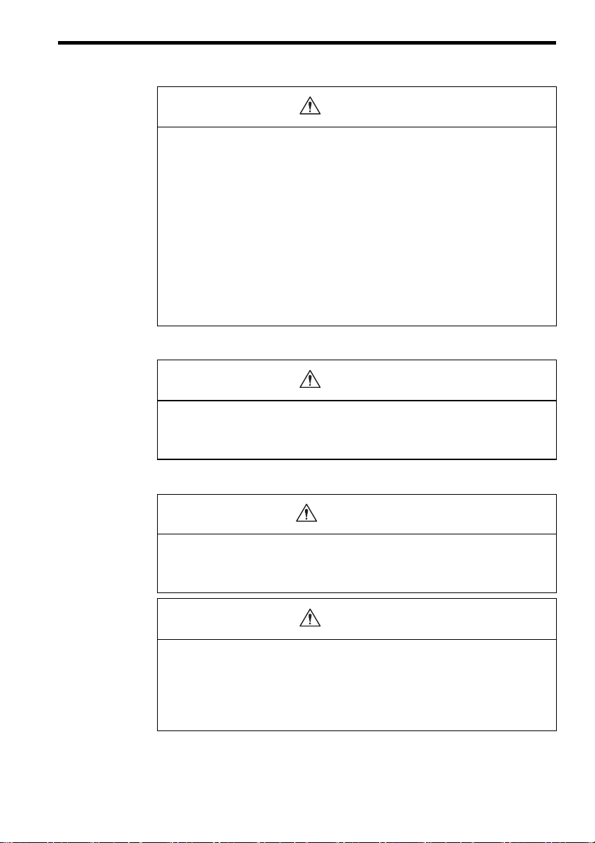
SYMBOLS FOR SAFE OPERATION
In this manual, the NOTES FOR SAFE OPERATION are classified as “WARNING” or
“CAUTION”. The following symbols are used.
WARNING
CAUTION
Indicates a potentially hazardous situation which, if not avoided, could result in
death or serious personal injury.
Indicates a potentially hazardous situation which, if not avoided, may result in
minor or moderate personal injury and/or damage to the equipment.
In some instances, items described in may also result in a serious accident.
In either case, follow these important items.
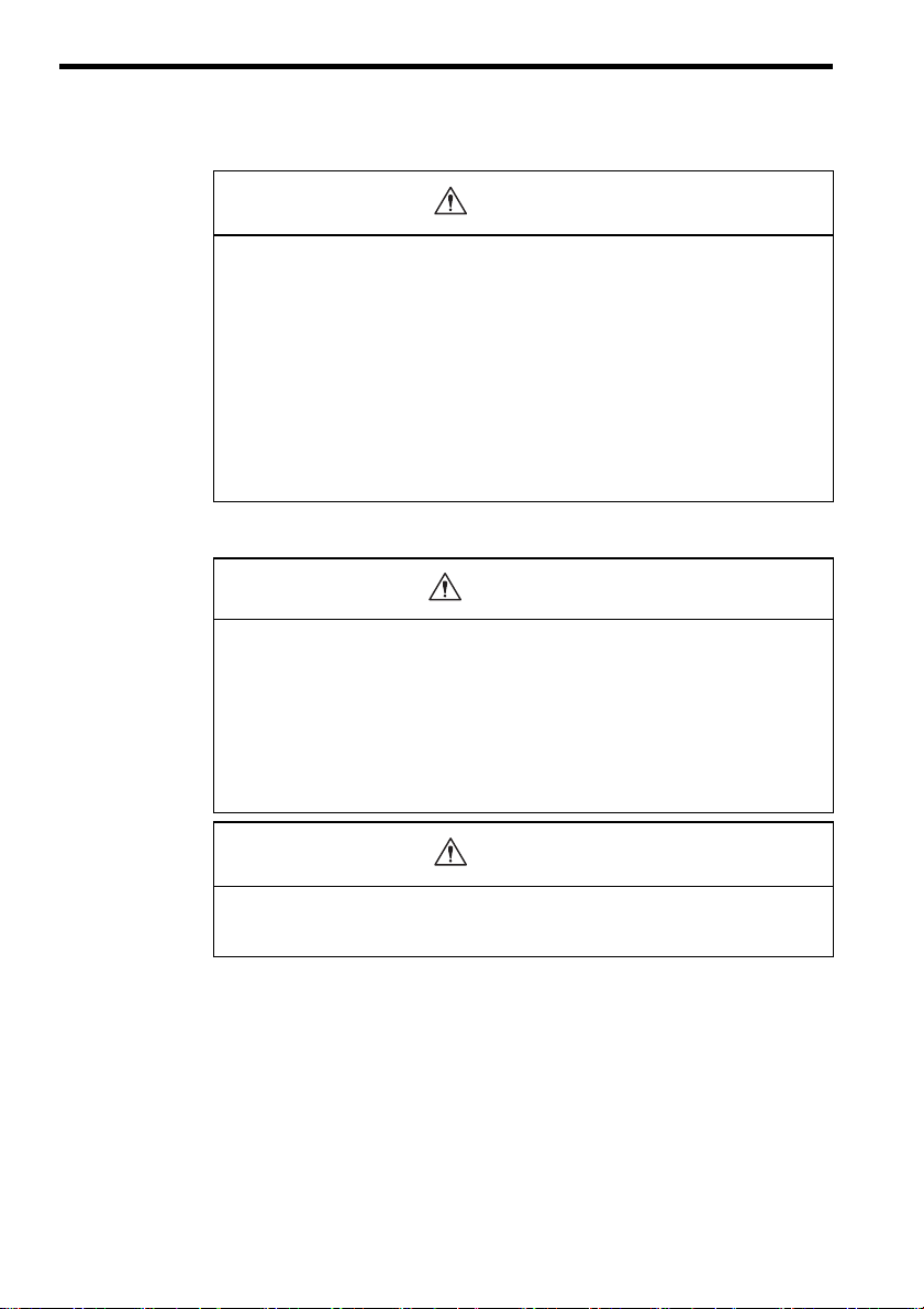
NOTES FOR SAFE OPERATION
Read this manual thoroughly before installation, operation, maintenance or inspection of the
AC Servo Drives.
CHECKING ON DELIVERY
• Do not apply or use the NS100 Module in conjunction with SGDH SERVOPACK
version 12.
There is a potential for an unintended servomotor brake release with the NS100 Module in
connection with the SGDH SERVOPACK version 12 and in connection with Σ-II motors
with holding brakes.
AN UNINTENDED RELEASE COULD RESULT IN INJURY TO PERSONS OR
EQUIPMENT IN CLOSE PROXIMITY TO ANY MECHINERY CONTROLLED BY
THE SERVO SYSTEM.
IN CLOSE PROXIMITY TO ANY MACHINERY CONTROLLED BY THE SERVO
SYSTEM.
In this product combination the motor holding brake will release 3 seconds after power is
supplied to the SGDH SERVOPACK even though the SERVOPACK is disabled (SERVO
ON signal is OFF).
CAUTION
WARNING
(Ref.No.)
E-9
E-4
Page 9
CAUTION
• There is a limitation in the combination of the software version of the SGDH SER-
VOPACK and the software version of the NS100 Module.
When the software version of the SGDH SERVOPACK is 11 or lower: Applicable to
all the versions of the NS100
When the software version of the SGDH SERVOPACK is 12 or higher: Applicable
to version 7 or higher of the NS100
When the wrong combination is used, an alarm A.BF SYSTEM ERROR (operation error)
may occur.
• When SGDH SERVOPACK is used with a NS100 Module mounted, the parame-
ters are automatically set so that the NS100 Module can be operated from the first
power ON.
For details of parameter setting methods, refer to Σ-II Series SGM/SGDH User’s Manual
Desine and Maintenance (SIE-S800-32.2).
INSTALLATION
CAUTION
• Never use the equipment where it may be exposed to splashes of water, corrosive
or flammable gases, or near flammable materials.
Failure to observe this caution may result in electric shock or fire.
WIRING
WARNING
• SERVOPACK grounding must be in accordance with the national code and consis-
tent with sound local practices.
Failure to observe this warning may result in electric shock or fire.
(Ref.No.)
E-9
E-10
(Ref.No.)
E-14
(Ref.No.)
E-17
CAUTION
• Do not connect three-phase power supply to SERVOPACK output terminals U, V,
and W.
Failure to observe this caution may lead to personal injury or fire.
• Securely tighten screws on the power supply and motor output terminals.
Failure to observe this caution may result in a fire.
E-5
(Ref.No.)
E-17
E-17
Page 10
OPERATION
CAUTION
• To avoid inadvertent accidents, run the servomotor only in test run (without load).
Failure to observe this caution may result in personal injury.
• Before starting operation with a load connected, set up parameters suitable for the
machine.
Starting operation without setting up parameters may result in machine overrun or failure.
• Before starting operation with a load connected, make sure emergency-stop proce-
dures are in place.
Failure to observe this caution may result in personal injury.
• During operation, do not touch the SERVOPACK’S heatsink.
Failure to observe this caution may result in burns.
INSPECTION AND MAINTENANCE
WARNING
• Never touch the inside of the SERVOPACKs.
Failure to observe this warning may result in electric shock.
• Never open the terminal cover while power is ON, and never turn ON power when
the terminal cover is open.
Failure to observe this warning may result in electric shock.
• After turning OFF power, wait at least five minutes before servicing the product.
Otherwise, residual electric charges may result in electric shock.
(Ref.No.)
E-20
E-20
E-20
E-21
(Ref.No.)
E-22
E-22
E-22
CAUTION
• Never change wiring while power is ON.
Failure to observe this caution may result in electric shock or personal injury.
E-6
(Ref.No.)
E-22
Page 11

General Precautions
Note the following to ensure safe application.
• Some drawings in this manual are shown with the protective cover or shields removed, in order to
describe the detail with more clarity. Make sure all covers and shields are replaced before operating this
product.
• Some drawings in this manual are shown as typical example and may differ from the shipped
product.
• This manual may be modified when necessary because of improvement of the product, modification or
changes in specifications.
Such modification is made as a revision by renewing the manual No.
• To order a copy of this manual, if your copy has been damaged or lost, contact your YASKAWA representative listed on the last page stating the manual No. on the front cover.
• YASKAWA is not responsible for accidents or damages due to any modification of the product made by
the user since that will void our guarantee.
WARNING LABEL
NS100
5
S
W
1
A
R
S
W
2
C
N
6
A
SERVOPACK warning label position
Disconnect all power and wait 5 min.
WARNING
before servcing. May cause electric shock.
Do not touch heat sink when power is ON.
CAUTION
May cause burn.
Use proper grounding techniques.
YASKAWA
SERVOPACK
SGDH- 200 V
C
N
6
B
C
N
4
SERVOPACK Warning Label and Grounding Mark Position
E-7
Page 12

1 PARTS
The NS100 Module parts names are as follows:
NS100
S
W
1
A
R
S
W
2
C
A
6
A
C
A
6
B
C
A
4
Ground wire for connecting to SERVOPACK
Rotary switch (SW1) for MECHATROLINK station
address settings
LED (A) for alarm
LED (R) for MECHATROLINK communication
DIP switch (SW2) for MECHATROLINK
communication settings
Nameplate with operation module type and serial
No.
MECHATROLINK communication connectors
(CN6A and CN6B)
Fully closed encoder signal connector (CN4)
E-8
Page 13

2 CHECKING ON DELIVERY
• Do not apply or use the NS100 Module in conjunction with the SGDH NS100 SERVOPACK
version 12.
There is a potential for an unintended servomotor brake release with the NS100 Module in connection
with the SGDH SERVOPACK version 12 and in connection with Σ-II motors with holding brakes.
AN UNINTENDED RELEASE COULD RESULT IN INJURY TO PERSONS OR EQUIPMENT IN
CLOSE PROXIMITY TO ANY MECHINERY CONTROLLED BY THE SERVO SYSTEM.
IN CLOSE PROXIMITY TO ANY MACHINERY CONTROLLED BY THE SERVO SYSTEM.
In this product combination the motor holding brake will release 3 seconds after power is supplied to the
SGDH SERVOPACK even though the SERVOPACK is disabled (SERVO ON signal is OFF).
Note: The brake release above occurs only when the software version 12 of
the SGDH SERVOPACK and any versions of the NS100 Module are
used together. It does not occur when only the SGDH SERVOPACK
is used or is used with any application modules other than the NS100
Module.
Check the software version of the SGDH SERVOPACK on the front
face underneath the model number or in the parameter Fn012.
Version tool:
∗∗∗ 12
Monitor mode: Fn012.
2
WARNING
The lower two digits of the software version
CHECKING ON DELIVERY
CAUTION
• There is a limitation in the combination of the software version of the SGDH SERVOPACK and
the software version of the NS100 Module.
When the software version of the SGDH SERVOPACK is 11 or lower: Applicable to all the ver-
sions of the NS100 Module
When the software version of the SGDH SERVOPACK is 12 or higher: Applicable to version 7
or higher of the NS100 Module
When the wrong combination is used, an alarm A.BF SYSTEM ERROR (operation error) may occur.
Note: Check the software version as follows:
Software version of the SGDH SERVOPACK: Lower two digit of the
version tool
Software version of the NS100 Module: Lower two digits of the version number in the nameplate
E-9
∗∗∗ 12
∗∗∗ 07
Page 14

• When SGDH SERVOPACK is used with a NS100 Module mounted, the parameters are auto-
matically set so that the NS100 Module can be operated from the first power ON.
For details of parameter setting methods, refer to Σ-II Series SGM/SGDH User’s Manual Desine and
Maintenance (SIE-S800-32.2).
2.1 Checking Items
When Σ-II Series products are delivered, check the following items:
Check Items Remarks
Check if the delivered products
are the ones you ordered.
Check if the motor shaft rotates
smoothly.
Check for damage. Check the overall appearance, and check for damage or scratches
Check if SERVOPACK is the
type applicable for NS100 Module?
If any of the above items are faulty or incorrect, contact the dealer from which you pur-
chased the products or your nearest local sales representative.
2.2 Appearance and Nameplate
CAUTION
Check the types marked on the nameplates of the NS100 Module.
If the motor shaft is smoothly turned by hand, it is normal. However, if the motor has brakes, it cannot be turned manually.
resulting from transportation.
Check the nameplate of SERVOPACK.
SERVOPACK Type
SGDH
-E-
c d
“SGDH” in c, and “E” in d
NS100
S
W
1
A
R
S
W
2
C
N
6
A
C
N
6
B
C
N
4
NS100 module
Order Number Protection class
SERVOPACK 1P1X
MECHATROLINK APPLICATION MODULE
MODEL JUSP-NS100 VER. 01000
CE marking
UL marking
E-10
Page 15

2.3 Type Designation
2
CHECKING ON DELIVERY
SERVOPACK peripheral device
Model
NS10: MECHATROLINLK interface
Design revision order
2.4 Mounting NS100 Module
Mount a NS100 Module on a SGDH SERVOPACK in the following manner. Provide the
screws for connecting ground wire as shown below.
Mounting
Method
Base
mounted
Rack
mounted
Duct
ventilated
SERVOPACK Type Screw Remarks
SGDH-A3 to 02BE
SGDH-A3 to 10AE
SGDH-15 to 50AE
SGDH-05 to 50DE
SGDH-60 to 1EAE
SGDH-60 to 1EDE
SGDH-A3 to 02BE-R
SGDH-A3 to 50AE-R
SGDH-05 to 50DE-R
SGDH-60 to 1EAE-P
SGDH-60 to 1EDE-P
1. Remove the connector cover mounted on CN10 of SERVOPACK.
SERVOPACK
JUSP
M3
×10 round head screws
(with spring washer and
plain washer)
M4
×10 round head screws
(with spring washer and
plain washer)
M4
×8 round head screws
(with spring washer and
plain washer)
M4
×6 round head screws
(with spring washer and
plain washer)
M4
×8 round head screws
(with spring washer and
plain washer)
YASKAWA
SERVOPACK
SGDH-
MODE/SET
DATA/
CHARGE
POWER
CN10
0
Connector
cover
-
NS10
Attachments.
Attachments.
Use the screw of the front panel.
Attachments.
Note: Make sure that spring washers and
plain washers are used for mounting.
(Otherwise, the screw for connecting
ground wire sticks out from the other
side of the flange, and the SERVO PACK cannot be mounted properly.)
Use the screw of the front panel.
E-11
Page 16

2. Mount a NS100 Module.
Connector (to SERVOPACK)
CN10
YASKAWA
SERVOPACK
SGDH-
3. For grounding, connect a ground wire of the NS100 Module to the marked “G” on the
SERVOPACK.
Ground wire
YASKAWA
SGDH-
G
SERVOPACK
NS100
DATA/
MODE/SET
CHARGE
POWER
For SERVOPACK (30 W to 5.0 kW)
G
YASKAWA
SERVOPACK 200 V
SGDH-
NS100
For SERVOPACK (6.0 kW to 7.5 kW)
E-12
Ground wire
Page 17

2
CHECKING ON DELIVERY
The appearance of SERVOPACK with application module properly mounted is shown
below
YASKAWA
SERVOPACK
SGDH-
NS100
S
W
1
A
R
S
W
2
C
N
6
A
C
N
6
B
C
N
4
E-13
Page 18

3 INSTALLATION
Σ-II Series SGDH SERVOPACK is a base-mount type servo controller. Incorrect installation
will cause problems. Always observe the installation instructions described below.
• Never use the equipment where it may be exposed to splashes of water, corrosive or flamma-
ble gases, or near flammable materials.
Failure to observe this caution may lead to electric shock or fire.
3.1 Storage
When the SERVOPACK is to be stored with the power cable disconnected, store it in the fol-
lowing temperature range:
Between -20 to +85°C
YASKAWA
SERVOPACK
SGDH- 200 V
CAUTION
NS100
S
W
1
A
R
S
W
2
C
N
6
A
C
N
6
B
C
N
4
S
-II Series
SGDH SERVOPACK with NS100 Module Mounted
E-14
Page 19

3.2 Installation Sites
For installation sites, use proper care with the following notes.
When installed in a control panel Design the control panel size, unit layout, and cooling method
When installed near a heating unit Suppress radiation heat from the heating unit and a tempera-
When installed near a source of
vibration
When installed in a place receiving
corrosive gases
Others Avoid installation in a hot and humid place or where excessive
3.3 Orientation
Install the SERVOPACK perpendicular to the wall as shown in the figure below.
The SERVOPACK must be orientated as shown in the figure.
Firmly secure the SERVOPACK through two to four mounting holes depending on the SER-
VOPACK capacity.
Situation Notes on Installation
so that the temperature around the periphery of the SERVOPACK does not exceed 55°C.
ture rise caused by convection so that the temperature around
the periphery of the SERVOPACK does not exceed 55°C.
Install a vibration isolator underneath the SERVOPACK to
prevent it from receiving vibration.
Corrosive gases do not immediately affect the SERVOPACK
but will eventually cause contactor-related devices to malfunction. Take appropriate action to protect against corrosive gases.
dust or iron powder is present in the air. Install in a place
where the altitude is 1000 m or less.
3
INSTALLATION
MADE IN JAPAN
Ventilation
E-15
Mounting face
Page 20

3.4 Installation Precations
When installing multiple SERVOPACKs side by side in a control panel, observe the follow-
ing installation method:
FAN FAN
5.0 mm (2in.) or more
10 mm (0.4in.) or more
30 mm (1.2in.) or more
5.0 mm (2in.) or more
Front Panel
Install SERVOPACK perpendicular to the wall so that the front panel (digital operator
mounted face) faces outward.
Cooling
Provide sufficient space around each SERVOPACK to allow cooling by fan and natural con-
vection.
Where mounted side by side
When installing SERVOPACKs side by side, provide at least 10mm (0.4in.) space between
them and at least 50mm (2in.) space above and below them as shown in the figure above.
Install cooling fans above the SERVOPACKs to prevent the temperature around each SER-
VOPACK from increasing excessively and also to maintain the temperature inside the con-
trol panel evenly.
Environments in Control Panel
Maintain the following conditions inside the control panel:
• Ambient temperature for SERVOPACK: 0 to 55°C
• Humidity: 90%RH or less
• Vibration: 4.9 m/s
• Condensation and freezing: None
• Ambient temperature to ensure long-term reliability: 45°C or less
• Altitude of 1000 m max.
2
E-16
Page 21

4 WIRING
4
WIRING
This section shows a standard example for connecting Σ-II series products to peripheral devices
and briefly explains how to connect each peripheral device.
WARNING
• SERVOPACK grounding must be in accordance with the national code and consistent with
sound local practices.
Failure to observe this warning may lead to electric shock or fire.
CAUTION
(WIRING)
• Do not connect three-phase power supply to SERVOPACK output terminals U, V and W.
Failure to observe this caution may lead to personal injury or fire.
• Securely tighten screws on the power supply and motor output terminals.
Failure to observe this caution can result in a fire.
For the following wiring, refer to Σ-II series SGMH/SGDH User ’s Manual Design and Main-
tenance (SIE-S800-32.2) and Σ-II series SGDH MECHATROLINK Interface Module User’s
Manual (SIE-C718-4).
• Main circuit wiring
• I/O signal wiring
• Encoder wiring
• Example of connections
E-17
Page 22

4.1 MECHATROLINK Connection Example
An example of MECHATROLINK connection is shown below.
Host controller
PS-03
YASKAWA
SGDH-
SERVOPACK
MP920 CPU-01 SVB-01 D1-01 DO-01
POWER
SW1
DC 24 V
12345678
LRST
RUN
INIT
-TEST
MULTI
FLASH
M. RST
ON OFF
PORT2
PORT2
TB1
+24 V
0 V
PORT1
FG
CN1
SG
NS100
RLY OUT
Motion controller
MP910, MP920, MP930,
Note: The total length of cable should be “L1 + L2 + ••• Ln≤50m”
CN1
CN1
RUN RUN
STATUS
PDY
RUN
ALM
ERF
BAT
ALM
PRT
PRT2
FUSE
TRK
CN2
CN2
CN1
...
L2 Ln
YASKAWA
SERVOPACK
SGDH-
NS100
Up to 15 sations can be connected.
L1
YASKAWA
SGDH-
SERVOPACK
NS100
E-18
Page 23

4.2 Precautions on Wiring
Take note the following precautions at wiring.
Connectable Maximum Number of Stations
Up to 15 slave stations can be connected.
Cables
Use the following cables.
Cable Type Length (m)
MECHATROLINK Communication Cable
(With connector on both ends)
For other peripheral devices, refer to Σ-II series SGMH/SGDH User’s Manual Design
and Maintenance (SIE-S800-32.2) and Σ-II series SGDH MECHATROLINK Interface
Module User’s Manual (SIE-C718-4).
Total cable length
The total cable length should be 50 m and less.
(Station 1 + Station 2 + ••• Station ≤ 50 m)
JEPMC-W6000-A3
JEPMC-W6000-A5
JEPMC-W6000-01
4
WIRING
0.3
0.5
1.0
Terminator
Be sure to install the following terminator on SERVOPACK of terminal station.
Terminator Type
MECHATROLINK Communication Terminator JEPMC-W6020
E-19
Page 24

5 OPERATION
This section provides precautions at test run and operation. For instructions on test run and
operation, refer to Σ-II series SGMH/SGDH User’s Manual Design and Maintenance (SIE-
S800-32.2) and Σ-II series SGDH MECHATROLINK Interface Module User’s Manual (SIE-
C718-4).
5.1 Precautions at Test Run
• To avoid inadvertent accidents, run the servomotor only in test run (without load).
Failure to observe this caution may result in personal injury.
• Before starting operation with a load connected, set up parameters suitable for the machine.
Starting operation without setting up parameters may lead to overrun failure.
• Before starting operation with a connected load, make sure emergency-stop procedures are in
place.
Failure to observe this caution may result in personal injury.
Conducting Test Run for Servomotor without Load
When servomotor is operated without load, set the load inertia (parameter Pn103) to 0.
(Factory setting is 0)
When servomotor is rotated without load (without load inertia), if the value has been set to
other than 0, the servomotor may oscillate.
To avoid this, make sure to set the load inertia to 0 and then servo ON.
CAUTION
Conducting Test Run with Servomotor Connected to Machine
SERVOPACK initial parameters setting is performed assuming normal operation conditions.
Before test run, set up parameters suitable for the machine.
Failure to set up the parameters initial setting may result in machine overrun or breakdown.
As for the setting procedures and methods, refer to Σ-II Series SGMH/SGDH User’s
Manual Design and Maintenance (SIE-S800-32.2).
Check Item during Test Run
The following items should be checked during test run.
• Unusual vibration
• Abnormal noise
• Excessive temperature rise
E-20
Page 25

5.2 Precautions at Operation
• During operation, do not touch the SERVOPACK’S heatsink.
Failure to observe this caution may result in burns.
CAUTION
5
OPERATION
E-21
Page 26

6 INSPECTION AND MAINTENANCE
This section describes the basic inspections and maintenance. If any failure occures on SER-
VOPACK, refer to Σ-II Series SGMH/SGDH User’s Manual Design and Maintenace Section
10.2 Troubleshooting (SIE-S800-32.2) and Σ-II Series SGDH MECHATROLINK Interface
Module User’s Manual (SIE-C718-4). Contact your Yaskawa representative if the problem can-
not be solved by the procedures described.
WARNING
• Be sure to turn OFF power before inspection or maintenance.
Otherwise, electric shock may result.
• Never open the terminal cover while power is ON, and never turn ON power when the terminal
cover is open.
Otherwise, electric shock may result.
• After turning OFF power, wait at least five minutes before servicing the product.
Otherwise, residual electric charges may result in electric shock.
CAUTION
• Never change wiring while power is ON.
Failure to observe this caution may result in electric shock or personal injury.
E-22
Page 27

7
MEASURES TO SATISFY THE EMC DIRECTIVE
7 MEASURES TO SATISFY THE EMC DIRECTIVE
This section describes the measures required for MECHATROLINK Interface Module to con-
form to EMC Directive (EN50081-2, EN50082-2).
7.1 MECHATROLINK Communication Cable
For serial communication (CN6A, CN6B) connector, use the connector for special use.
Max. cable length is 50 m.
Use the twisted pair shielded cable.
7.2 Fully Closed Encoder Cable
For fully closed encoder (CN4) connector, use the following connector.
Use the twisted pair shielded cable.
Connector: 54306-2011 (Made by Molex Japan Co., Ltd.)
Connector case: 54331-0201 (Made by Molex Japan Co., Ltd.)
7.3 The Core on the Cable
Attach the core on the cable as shown below:
Core Model ESD-SR-25
Quantity 1
Turn 2
Manufacturer Tokin.Corp.
Cable
Core
Cable line and the line position where the core are attached are shown below.
Cable Name Mounting Position of Core
MECHATROLINK Communication Cable Near the host controller and SERVOPACK side
Fully Closed Encoder Cable Near the SERVOPACK side
E-23
Page 28

7.4 Cable Clamp
Fix and ground the cable shield using a piece of conductive metal.
<Example of Cable Clamp>
SERVOPACK side
Cable
Clamp
Ground plate
Cable
Shield (cable sheath stripped)
Fix and ground the cable shield
using a piece of conductive metal.
Remove paint on mounting surface.
E-24
Page 29

7.5 Wiring Examples
The following diagrams show the wiring example. Before wiring, turn OFF the Power ON/
OFF switch and post a notice of “No Conduction”. Only an electrical expert can perform the
wiring. The noise filter and the core are shown in the diagram.
7
MEASURES TO SATISFY THE EMC DIRECTIVE
<REQUIRED EN SPECIFICATIONS>
Three-phase
400 V
Main
power
supply
Control
power
supply
Signal-phase
200 VAC
Clamp
Clamp
Noise
filter 1
Note: 1. Clamp: Secure cable shields and ground for conductive metal parts.
2. Make sure that the grounding plate are securely connected to the grounding.
3. Remove the paint from the grounding plate to insure a good Earth connection for filter,
SERVOPACK, clamp, etc.
Noise
filter 2
AC/DC
converter
Grounding plate/Box
Control box
CN1
SGDH
SERVOPACK
L1, L2, L3
A1, A2
U, V, W, CN2
Clamp Clamp Clamp Clamp
Moter
Encoder
Servomotor
I/F module
JUSP-NS100
CoreCore
Core
Core Core
CN6A
Core
CN6B
Core
Core
Open
Host controller
CoreCore
E-25
Page 30

AC SERVOPACK
Σ-II Series
INSTRUCTIONS
MECHATROLINK Interface Module
IRUMA BUSINESS CENTER (SOLUTION CENTER)
480, Kamifujisawa, Iruma, Saitama 358-8555, Japan
Phone 81-4-2962-5151 Fax 81-4-2962-6138
http://www.yaskawa.co.jp
YASKAWA AMERICA, INC.
2121 Norman Drive South, Waukegan, IL 60085, U.S.A.
Phone 1-800-YASKAWA (927-5292) or 1-847-887-7000 Fax 1-847-887-7310
http://www.yaskawa.com
YASKAWA ELÉTRICO DO BRASIL LTDA.
Avenida Piraporinha 777, Diadema, São Paulo, 09950-000, Brasil
Phone 55-11-3585-1100 Fax 55-11-3585-1187
http://www.yaskawa.com.br
YASKAWA EUROPE GmbH
Hauptstraβe 185, Eschborn 65760, Germany
Phone 49-6196-569-300 Fax 49-6196-569-398
http://www.yaskawa.eu.com
YASKAWA ELECTRIC KOREA CORPORATION
9F, Kyobo Securities Bldg. 26-4, Yeouido-dong, Yeongdeungpo-gu, Seoul, 150-737, Korea
Phone 82-2-784-7844 Fax 82-2-784-8495
http://www.yaskawa.co.kr
YASKAWA ELECTRIC (SINGAPORE) PTE. LTD.
151 Lorong Chuan, #04-02A, New Tech Park 556741, Singapore
Phone 65-6282-3003 Fax 65-6289-3003
http://www.yaskawa.com.sg
YASKAWA ELECTRIC (CHINA) CO., LTD.
12F, Carlton Bld., No.21 HuangHe Road, HuangPu District, Shanghai 200003, China
Phone 86-21-5385-2200 Fax 86-21-5385-3299
http://www.yaskawa.com.cn
YASKAWA ELECTRIC (CHINA) CO., LTD. BEIJING OFFICE
Room 1011, Tower W3 Oriental Plaza, No.1 East Chang An Ave.,
Dong Cheng District, Beijing 100738, China
Phone 86-10-8518-4086 Fax 86-10-8518-4082
YASKAWA ELECTRIC TAIWAN CORPORATION
9F, 16, Nanking E. Rd., Sec. 3, Taipei 104, Taiwan
Phone 886-2-2502-5003 Fax 886-2-2505-1280
YASKAWA ELECTRIC CORPORATION
In the event that the end user of this product is to be the military and said product is to be employed in any weapons systems or the manufacture
thereof, the export will fall under the relevant regulations as stipulated in the Foreign Exchange and Foreign Trade Regulations. Therefore, be sure to
follow all procedures and submit all relevant documentation according to any and all rules, regulations and laws that may apply.
Specifications are subject to change without notice for ongoing product modifications and improvements.
© 1999-2014 YASKAWA ELECTRIC CORPORATION. All rights reserved.
MANUAL NO. TOB-C718-4C
Published in Japan January 2014 99-3
13-6-9
15
-0
Page 31

한국 전파법에 관한 주의사항
韓国電波法に関連する注意事項
Precautions for Korean Radio Waves Act
针对韩国电波法的注意事项
기종별 사용자 안내문
A급 기기
( 업무용 방송 통신기 자재 )
이 기기는 업무용 (A 급 ) 전자파 적합 기기로서 판매자
또는 , 사용자는 이 점을 주의하시기 바라며 , 가정외의
지역에서 사용하는 것을 목적으로 합니다 .
사용자 안내문
 Loading...