

Page 1
General Precautions
CAUTION
PROHIBITED
MANDATORY
WARNING
CAUTION
CAUTION
CAUTION
Use proper grounding techniques.
OPTION MODULEOPTION MODULE
MODELMODEL SGDV-OCA01ASGDV-OCA01A
Serial number
Model
MANUAL NO. TOBP C720829 00D
Option Module
AC SERVOPACK
SAFETY PRECAUTIONS
Option Module Model: SGDV-OAA
To properly use the product, read this manual thoroughly and retain
for easy reference, inspection, and maintenance. Ensure the end user
receives this manual.
Σ-V
Series/
Σ-V
Series for Large-Capacity Models/
Σ
-7 Series
• The drawings presented in this manual are sometimes shown without covers or pro-
tective guards. Always replace the cover or protective guard as specified first, and
then operate the products in accordance with the manual.
• The drawings presented in this manual are typical examples and may not match the
product you received.
• This manual is subject to change due to product improvement, specification modifi-
cation, and manual improvement. When this manual is revised, the manual code is
updated and the new manual is published as a next edition. The edition number
appears on the front and back covers.
• Yaskawa will not take responsibility for the results of unauthorized modifications of
this product. Yaskawa shall not be liable for any damages or troubles resulting from
unauthorized modification.
Safety Information
The following conventions are used to indicate precautions in this manual. Failure to
heed precautions provided in this manual can result in serious or possibly even fatal
injury or damage to the products or to related equipment and systems.
WARNING
Indicates precautions that, if not heeded, could possibly result in
loss of life or serious injury.
Indicates precautions that, if not heeded, could result in relatively
serious or minor injury, damage to the product, or faulty operation.
In some situations, the precautions indicated could have serious
consequences if not heeded.
Indicates prohibited actions that must not be performed. For example, this symbol would be used to indicate that fire is prohibited as
follows: .
Indicates compulsory actions that must be performed. For example,
this symbol would be used as follows to indicate that grounding is
compulsory: .
Notes for Safe Operation
• Never touch any rotating motor parts while the motor is running.
Failure to observe this warning may result in injury.
• Before starting operation with a machine connected, make sure that an emer-
gency stop can be applied at any time.
Failure to observe this warning may result in injury or damage to the product.
• Never touch the inside of the SERVOPACKs.
Failure to observe this warning may result in electric shock.
• Do not remove the cover of power supply terminal while the power is ON.
Failure to observe this warning may result in electric shock.
• Σ-V SERVOPACKs or Σ-7 SERVOPACKs: Do not touch the power supply ter-
minals while the CHARGE lamp is ON because high voltage may still remain in
the SERVOPACK after turning power OFF. Make sure the charge indicator is
OFF first before starting to do wiring or inspections.
Residual voltage may cause electric shock.
• Large-Capacity Σ-V SERVOPACKs: Do not touch the power terminals while
discharging the main circuit's capacitor, because high voltage may still remain
in the SERVOPACK and the converter after turning power OFF. For details on
the charging time of the main circuit’s capacitor, refer to 3.2 Discharging Time
of the Main Circuit’s Capacitor in Large-Capacity
Setup. Before starting to do wiring or inspections, confirm that the charge indi-
cator is OFF and that the power has been completely discharged by using a
tester to measure the voltage between the P and N terminals for DC power.
Residual voltage may cause electric shock.
• Follow the procedures and instructions for the trial operation as noted in the
applicable manual for that product.
Malfunctions that occur after the servomotor is connected to the equipment not
only damage the equipment, but may also cause an accident resulting in death
or injury.
• The output range of multi-turn data for Σ-V, large-capacity Σ-V, or Σ-7 series
absolute detection system differs from that for conventional systems (15-bit
encoder and 12-bit encoder). Especially when “Infinite length positioning sys-
tem” of Σ series is to be configured with Σ-V, large-capacity Σ-V, or Σ-7 series,
be sure to make the system modification.
• The multi-turn limit value must be changed only for special applications.
Changing it inappropriately or unintentionally can be dangerous.
• If the Multi-turn Limit Disagreement alarm occurs, check the setting of parame-
ter Pn205 in the SERVOPACK to be sure that it is correct.
If Fn013 is executed when an incorrect value is set in Pn205, an incorrect
value will be set in the encoder. The alarm will disappear even if an incorrect
value is set, but incorrect positions will be detected, resulting in a dangerous
situation where the machine will move to unexpected positions.
• Do not remove the front cover, cables, connectors, or optional items on the
foreside while the power is ON.
Failure to observe this warning may result in electric shock.
• Do not damage, press, exert excessive force or place heavy objects on the
cables.
Failure to observe this warning may result in electric shock, stopping operation
of the product, or fire.
• Do not modify the product.
Failure to observe this warning may result in injury, damage to the product, or
fire.
• Provide an appropriate stopping device on the machine side to ensure safety.
A holding brake for a servomotor with brake is not a stopping device for ensuring safety.
Failure to observe this warning may result in injury.
• Do not come close to the machine immediately after resetting momentary
power loss to avoid an unexpected restart. Take appropriate measures to
ensure safety against an unexpected restart.
Failure to observe this warning may result in injury.
• Connect the ground terminal to electrical codes (ground resistance: 100 Ω or
less for a SERVOPACK with a 200 V/100 V power supply. 10 Ω or less for a
SERVOPACK with a 400 V power supply).
Improper grounding may result in electric shock or fire.
• Installation, disassembly, or repair must be performed only by authorized per-
sonnel.
Failure to observe this warning may result in electric shock or injury.
• The person who designs a system using the safety function (Hard Wire Base-
block function) must have full knowledge of the related safety standards and
full understanding of the instructions in the applicable manual for that product.
Failure to observe this warning may result in injury or damage to the product.
Storage and Transportation
Σ
-V Series User’s Manual
CAUTION
• Do not store or install the product in the following places.
• Locations subject to direct sunlight.
• Locations subject to temperatures outside the range specified in the storage/
installation temperature conditions.
• Locations subject to humidity outside the range specified in the storage/installation humidity conditions.
• Locations subject to condensation as the result of extreme changes in temperature.
• Locations subject to corrosive or flammable gases.
• Locations subject to dust, salts, or iron dust.
• Locations subject to exposure to water, oil, or chemicals.
• Locations subject to shock or vibration.
Failure to observe this caution may result in fire, electric shock, or damage to the
product.
• Do not hold the product by the cables, motor shaft, or detector while transporting it.
Failure to observe this caution may result in injury or malfunction.
CAUTION
• Do not place any load exceeding the limit specified on the packing box.
Failure to observe this caution may result in injury or malfunction.
• If disinfectants or insecticides must be used to treat packing materials such as
wooden frames, pallets, or plywood, the packing materials must be treated before
the product is packaged, and methods other than fumigation must be used.
Example: Heat treatment, where materials are kiln-dried to a core temperature of
56°C for 30 minutes or more.
If the electronic products, which include stand-alone products and products installed
in machines, are packed with fumigated wooden materials, the electrical components may be greatly damaged by the gases or fumes resulting from the fumigation
process. In particular, disinfectants containing halogen, which includes chlorine, fluorine, bromine, or iodine can contribute to the erosion of the capacitors.
Installation
CAUTION
• Never use the products in an environment subject to water, corrosive gases, inflam-
mable gases, or combustibles.
Failure to observe this caution may result in electric shock or fire.
• Do not step on or place a heavy object on the product.
Failure to observe this caution may result in injury or malfunction.
• Do not cover the inlet or outlet ports and prevent any foreign objects from entering
the product.
Failure to observe this caution may cause internal elements to deteriorate resulting
in malfunction or fire.
• Be sure to install the product in the correct direction.
Failure to observe this caution may result in malfunction.
• Provide the specified clearances between the SERVOPACK and the control panel
or with other devices.
Failure to observe this caution may result in fire or malfunction.
• Do not apply any strong impact.
Failure to observe this caution may result in malfunction.
• Observe the instructions in the instruction manual included in the package when
installing the option module to the SERVOPACK.
Failure to observe this caution may result in the malfunction.
Wiring
CAUTION
• Be sure to wire correctly and securely.
Failure to observe this caution may result in motor overrun, injury, or malfunction.
• Do not connect a commercial power supply to the U, V, or W servomotor connection
terminals.
Failure to observe this caution may result in injury or fire.
• Securely connect the power supply terminal screws and servomotor connection ter-
minal screws.
Failure to observe this caution may result in fire.
• Do not bundle or run the main circuit cables and input/output signal lines, the
encoder cables or communication cable together in the same duct. Keep power and
signal lines separated by at least 30 cm.
• Use twisted-pair shielded wires or multi-core twisted pair shielded wires for input/
output signal lines and the encoder cables.
The maximum length is 3 m for input/output signal lines and 20 m for encoder
cables.
• Observe the following precautions when wiring main circuit terminal blocks.
• If the main circuit terminal is the connector, remove the connector from the SERVOPACK prior to wiring.
• Insert only one wire per insertion slot on the terminal block and the connector.
• Make sure that the core wire is not electrically shorted to adjacent core wires.
• Install the battery at either the host controller and the battery unit of the encoder.
It is dangerous to install batteries at both simultaneously, because that sets up a
loop circuit between the batteries.
• Always use the specified power supply voltage.
An incorrect voltage may result in fire.
• Take appropriate measures to ensure that the input power supply is supplied within
the specified voltage fluctuation range. Be particularly careful in places where the
power supply is unstable.
An incorrect power supply may result in damage to the product.
• Install external breakers or other safety devices against short-circuiting in external
wiring.
Failure to observe this caution may result in fire.
• Take appropriate and sufficient countermeasures for each when installing systems
in the following locations.
• Locations subject to static electricity or other forms of noise.
• Locations subject to strong electromagnetic fields and magnetic fields.
• Locations subject to possible exposure to radioactivity.
• Locations close to power supplies.
Failure to observe this caution may result in damage to the product.
• Do not reverse the polarity of the battery when connecting it.
Failure to observe this caution may damage the battery, SERVOPACK, and servomotor or cause it to explode.
• Wiring or inspection must be performed by a technical expert.
Operation
• Conduct trial operation on the servomotor alone with the motor shaft disconnected
from machine to avoid any unexpected accidents.
Failure to observe this caution may result in injury.
• Before starting operation with a machine connected, change the settings to match
the parameters of the machine.
Starting operation without matching the proper settings may cause the machine to
run out of control or malfunction.
• Avoid frequently turning power ON and OFF.
Since the SERVOPACK has a capacitor in the power supply, a high charging current
flows when power is turned ON. Frequently turning power ON and OFF causes
main power devices like capacitors and fuses to deteriorate, resulting in unexpected
problems.
• Forced stop function with forward/reverse overtravel is not effective during JOG
mode operation using utility function Fn002 and zero point search using Fn003.
• When using the servomotor for a vertical axis, install the safety devices to prevent
workpieces to fall off due to occurrence of alarm or overtravel. Set the servomotor
so that it will stop in the zero clamp state at occurrence of overtravel.
Failure to observe this caution may cause workpieces to fall off due to overtravel.
• When not using the tuning-less function, set to the correct moment of inertia ratio
Pn103.
Setting to an incorrect moment of inertia ratio may cause vibration.
• Do not touch the SERVOPACK heatsinks, regenerative resistor, or servomotor while
power is ON or soon after the power is turned OFF.
Failure to observe this caution may result in burns due to high temperatures.
• Do not make any extreme adjustments or setting changes of parameters.
Failure to observe this caution may result in injury or damage to the product due to
unstable operation.
• When an alarm occurs, remove the cause, reset the alarm after confirming safety,
and then resume operation.
Failure to observe this caution may result in damage to the product, fire, or injury.
• Do not use the holding brake of the servomotor for braking.
Failure to observe this caution may result in malfunction.
• Always use the servomotor and SERVOPACK in one of the specified combinations.
Failure to observe this caution so may result in fire or malfunction.
• The servomotor stopping method of turning the main-circuit or control-circuit power
OFF without turning the servo OFF during operation can not be set in Parameter
Pn001.
• When turning the main-circuit power OFF without turning the servo OFF:
The servomotor will be stopped by dynamic braking (DB).
• When turning the control-circuit power OFF without turning the servo OFF:
The stopping method will vary depending on the SERVOPACK model.
For details, refer to the applicable manual for that product.
Maintenance and Inspection
• Do not disassemble the SERVOPACK/option module.
Failure to observe this caution may result in electric shock or injury.
• Do not attempt to change wiring while the power is ON.
Failure to observe this caution may result in electric shock or injury.
• When replacing the SERVOPACK, resume operation only after transferring the pre-
vious SERVOPACK parameters to the new SERVOPACK.
Failure to observe this caution may result in damage to the product.
• Always leave the option module attached to the SERVOPACK when sending the
option module to YASKAWA for service.
Disposal
• When disposing of the products, treat them as ordinary industrial waste.
Warranty Information
Free Warranty Period
This product is warranted for twelve months after being delivered to
Yaskawa’s customer or if applicable eighteen months from the date of shipment from Yaskawa’s factory whichever comes first.
Scope of Warranty
• Attach the nameplate included in the package to the designated location on the module cover. This product is under
warranty only when the nameplate is attached.
If a Yaskawa product is found to be defective due to Yaskawa workmanship or
materials and the defect occurs during the warranty period, Yaskawa will provide a replacement, repair the defective product, and provide shipping to and
from the site free of charge.
However, if the Yaskawa Authorized Service Center determines that the problem with a Yaskawa product is not due to defects in Yaskawa’s workmanship
or materials, then the customer will be responsible for the cost of any necessary repairs.
1 Checking Products on Delivery
Check the following items when the option module is delivered.
Items Check Method
Is the delivered option module the one that
was ordered?
Is there any damage?
Are there any loose screws? Check screws for looseness using a screwdriver.
Check the model numbers marked on the nameplates of the option module included in the package. Check the accessories as well.
Check the appearance, and check for damage or
scratches that may have occurred during shipping.
If any of the above items are faulty or incorrect, contact your Yaskawa sales
representative or the dealer from whom you purchased the products.
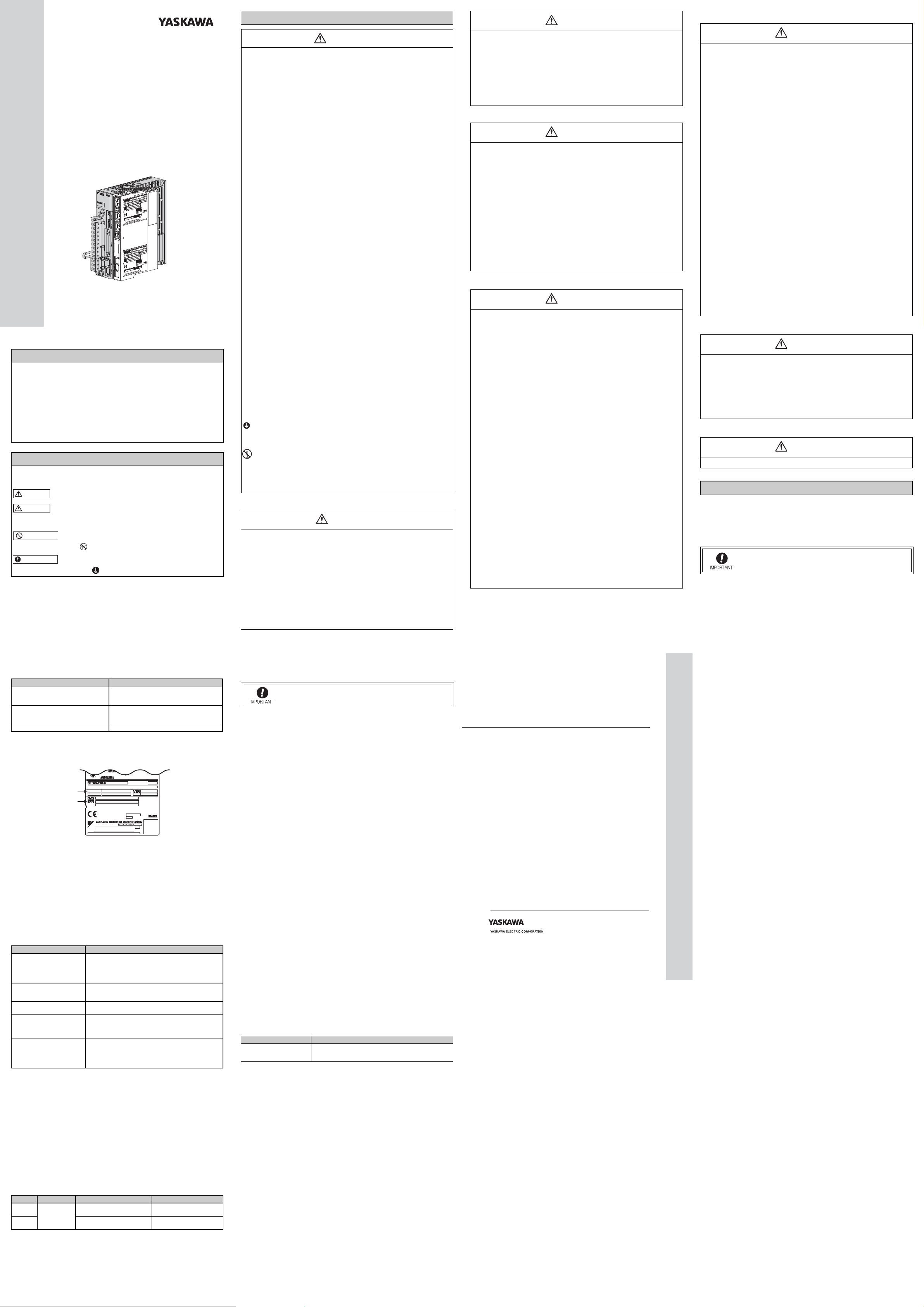
1.1 Nameplate
Option module nameplate
2 Installation
Observe the instructions in the manuals below when mounting the SERVOPACK with the option module already installed.
• Σ-V SERVOPACKs: Σ-V Series User’s Manual Setup Rotational Motor/Linear Motor (Manual No.: SIEP S800000 43/44)
• Large-Capacity Σ-V SERVOPACKs: Σ-V Series User’s Manual For Use with
Large-Capacity Models Setup (Manual No.: SIEP S800000 89)
• Σ-7 SERVOPACKs: Product Manuals for Σ-7 Series Σ-7S SERVOPACKs
• User’s Manual for the relevant optional module
For installation sites, use proper care with the following notes.
Situation Notes on Installation
When installed in a control panel
When installed near a heating
unit
When installed near a source of
vibration
When installed in a place receiving corrosive gases
Others
3 Wiring
Observe the instructions in the manuals below when mounting the SERVOPACK with the option module already installed.
• Σ-V SERVOPACKs: Σ-V Series User’s Manual Setup Rotational Motor/Lin-
ear Motor (Manual No.: SIEP S800000 43/44)
• Large-Capacity Σ-V SERVOPACKs: Σ-V Series User’s Manual For Use with
Large-Capacity Models Setup (Manual No.: SIEP S800000 89)
• Σ-7 SERVOPACKs: Product Manuals for Σ-7 Series Σ-7S SERVOPACKs
• User's Manual for the relevant optional module
• Design the control panel size, unit layout, and cooling
method so that the surrounding air temperature of the SERVOPACK does not exceed 55°C.
• When installing multiple SERVOPACKs side by side in a
control panel, install cooling fans.
Suppress radiation heat from the heating unit and a temperature rise caused by convection so that the surrounding air
temperature of the SERVOPACK does not exceed 55°C.
Install a vibration isolator underneath the SERVOPACK to
prevent it from receiving vibration.
Corrosive gases do not immediately affect the SERVOPACK
but will eventually cause SERVOPACK or contactor-related
devices to malfunction. Take appropriate action to protect
against corrosive gases.
• Avoid installation in a hot and humid place or where excessive dust or iron powder is present in the air.
• Be sure there is no condensation or freezing.
• Keep the surrounding air temperature 45 °C or less to
ensure long-term reliability.
5 If You Need to Send Us the Option Module for
Service
• Always leave the option module attached to the SERVOPACK
when sending the option module to YASKAWA for service.
6 Compliance with CE Marking
6.1 Installation Conditions of EMC Directive
To adapt the EMC directives (EN55011 group1 classA, EN61800-3) for a
combination test using servomotors and SERVOPACKs from the Σ-V, large-
capacity Σ-V, or Σ-7 series, a ferritic core, a noise filter, or a surge absorber
must be used. For details on how to mount the SERVOPACK with the option
module already installed, read the instructions in the manuals below.
• Σ-V SERVOPACKs: Σ-V Series User’s Manual Setup Rotational Motor/Lin-
ear Motor (Manual No.: SIEP S800000 43/44)
• Large-Capacity Σ-V SERVOPACKs: Σ-V Series User’s Manual For Use with
Large-Capacity Models Setup (Manual No.: SIEP S800000 89)
• Σ-7 SERVOPACKs: Product Manuals for Σ-7 Series Σ-7S SERVOPACKs
• User's Manual for the relevant optional module
However, because this product is built-in, check that the following conditions
are still met after being installed in the final product.
6.2 Conditions Corresponding to Low Voltage Direc-
tive
Observe the instructions in the manuals below.
• Σ-V SERVOPACKs: Σ-V Series Safety Precautions (Manual No.: TOMP
C710800 10)
• Large-Capacity Σ-V SERVOPACKs: Σ-V Series Safety Precautions For Use
with Large-Capacity Models (Manual No.: TOMP C710829 07)
• Σ-7 SERVOPACKs: Σ-7 Series Σ-7S and Σ-7W SERVOPACKs Safety
Precautions (Manual No.: TOMP C710828 00)
7 Installation Conditions of UL Standards
Observe the instructions in the manuals below.
• Σ-V SERVOPACKs: Σ-V Series Safety Precautions (Manual No.: TOMP
C710800 10)
• Large-Capacity Σ-V SERVOPACKs: Large-Capacity Σ-V Series Safety Precautions (Manual No.: TOMP C710829 07)
• Σ-7 SERVOPACKs: Σ-7 Series Σ-7S and Σ-7W SERVOPACKs Safety
Precautions (Manual No.: TOMP C710828 00)
한국 전파법에 관한 주의사항
韓国電波法に関連する注意事項
Precautions for Korean Radio Waves Act
针对韩国电波法的注意事项
사용자 안내문
기종별 사용자 안내문
A급 기기
( 업무용 방송 통신기 자재 )
이 기기는 업무용 (A 급 ) 전자파 적합 기기로서 판매자
또는 , 사용자는 이 점을 주의하시기 바라며 , 가정외의
지역에서 사용하는 것을 목적으로 합니다 .
AC SERVOPACK
Σ-V Series/
Σ-V Series for Large-Capacity Models/
Σ-7 Series
SAFETY PRECAUTIONS
Option Module
IRUMA BUSINESS CENTER (SOLUTION CENTER)
480, Kamifujisawa, Iruma, Saitama, 358-8555, Japan
Phone 81-4-2962-5151 Fax 81-4-2962-6138
http://www.yaskawa.co.jp
YASKAWA AMERICA, INC.
2121, Norman Drive South, Waukegan, IL 60085, U.S.A.
Phone 1-800-YASKAWA (927-5292) or 1-847-887-7000 Fax 1-847-887-7310
http://www.yaskawa.com
YASKAWA ELÉTRICO DO BRASIL LTDA.
777, Avenida Piraporinha, Diadema, São Paulo, 09950-000, Brasil
Phone 55-11-3585-1100 Fax 55-11-3585-1187
http://www.yaskawa.com.br
YASKAWA EUROPE GmbH
185, Hauptstraβe, Eschborn, 65760, Germany
Phone 49-6196-569-300 Fax 49-6196-569-398
http://www.yaskawa.eu.com
YASKAWA ELECTRIC KOREA CORPORATION
9F, Kyobo Securities Bldg. 26-4, Yeouido-dong, Yeongdeungpo-gu, Seoul, 150-737, Korea
Phone 82-2-784-7844 Fax 82-2-784-8495
http://www.yaskawa.co.kr
YASKAWA ELECTRIC (SINGAPORE) PTE. LTD.
151, Lorong Chuan, #04-02A, New Tech Park, 556741, Singapore
Phone 65-6282-3003 Fax 65-6289-3003
http://www.yaskawa.com.sg
YASKAWA ELECTRIC (THAILAND) CO., LTD.
252/125-126, 27th Floor, Muang Thai-Phatra Tower B, Rachadapisek Road, Huaykwang, Bangkok, 10310, Thailand
Phone 66-2693-2200 Fax 66-2693-4200
http://www.yaskawa.co.th
YASKAWA ELECTRIC (CHINA) CO., LTD.
22F, One Corporate Avenue, No.222, Hubin Road, Shanghai, 200021, China
Phone 86-21-5385-2200 Fax 86-21-5385-3299
http://www.yaskawa.com.cn
YASKAWA ELECTRIC (CHINA) CO., LTD. BEIJING OFFICE
Room 1011, Tower W3 Oriental Plaza, No.1, East Chang An Ave.,
Dong Cheng District, Beijing, 100738, China
Phone 86-10-8518-4086 Fax 86-10-8518-4082
YASKAWA ELECTRIC TAIWAN CORPORATION
9F, 16, Nanking E. Rd., Sec. 3, Taipei, 104, Taiwan
Phone 886-2-2502-5003 Fax 886-2-2505-1280
In the event that the end user of this product is to be the military and said product is
to be employed in any weapons systems or the manufacture thereof, the export will
fall under the relevant regulations as stipulated in the Foreign Exchange and Foreign
Trade Regulations. Therefore, be sure to follow all procedures and submit all relevant
documentation according to any and all rules, regulations and laws that may apply.
Specifications are subject to change without notice for ongoing product modifications
and improvements.
© 2009-2015 YASKAWA ELECTRIC CORPORATION
MANUAL NO. TOBP C720829 00D <9>-0
Published in Japan April 2015
14-9-10
Original instructions
4 Inspection
4.1 Option Module Inspection
For inspections and maintenance of the option module, follow the inspection
procedures in the table below at least once every year.
Item Frequency Procedure Remedy
Exterior
Loose
screws
4.2 Option Module’s Replacement Schedule
Refer to the instructions in the User's Manual for the relevant optional module.
At least once a
year
Check for dust, dirt, and oil on
surfaces.
Check for loose terminal block
and connector screws.
Clean with compressed air or
cloth.
Tighten any loose screws.
 Loading...