

Page 1

Low Harmonic Drive for HVAC Applications
Z1000U HVAC MATRIX Drive
Programming Manual
Type: CIMR-ZU
Models:
To properly use the product, read this manual thoroughly and retain
for easy reference, inspection, and maintenance. Ensure the end user
receives this manual.
200 V Class: 7.5 to 75 kW (10 to 100 HP ND)
400 V Class: 5.5 to 260 kW (7.5 to 350 HP ND)
MANUAL NO. SIEP C710636 10C
Parameter Details
Periodic Inspection &
Maintenance
Parameter List
MEMOBUS/Modbus
Communications
B
1
C
2
D
A
E
B
Page 2

Copyright © 2014 YASKAWA ELECTRIC CORPORATION. All rights reserved.
No part of this publication may be reproduced, stored in a retrieval system, or transmitted, in any form or by any means,
mechanical, electronic, photocopying, recording, or otherwise, without the prior written permission of Yaskawa. No patent
liability is assumed with respect to the use of the information contained herein. Moreover, because Yaskawa is constantly
striving to improve its high-quality products, the information contained in this manual is subject to change without notice.
Every precaution has been taken in the preparation of this manual. Yaskawa assumes no responsibility for errors or omissions.
Neither is any liability assumed for damages resulting from the use of the information contained in this publication.
Page 3

Table of Contents
1. PARAMETER DETAILS ................................................................................... 9
1.1 A: Initialization........................................................................................................... 10
A1: Initialization ....................................................................................................................... 10
A2: User Parameters............................................................................................................... 14
1.2 b: Application............................................................................................................. 16
b1: Operation Mode Selection................................................................................................. 16
b2: DC Injection Braking.......................................................................................................... 21
b3: Speed Search.................................................................................................................... 23
b4: Timer Function .................................................................................................................. 30
b5: PID Control........................................................................................................................ 31
b8: Energy Saving ................................................................................................................... 44
1.3 C: Tuning.................................................................................................................... 46
C1: Acceleration and Deceleration Times ............................................................................... 46
C2: S-Curve Characteristics.................................................................................................... 47
C4: Torque Compensation ...................................................................................................... 48
C6: Carrier Frequency............................................................................................................. 49
Rated Current Depending on Carrier Frequency .................................................................... 50
C7: Voltage Adjustment........................................................................................................... 51
1.4 d: Reference Settings ............................................................................................... 52
d1: Frequency Reference........................................................................................................ 52
d2: Frequency Upper/Lower Limits ......................................................................................... 53
d3: Jump Frequency................................................................................................................ 54
d4: Frequency Reference Hold and Up/Down 2 Function....................................................... 55
d6: Field Weakening................................................................................................................ 56
d7: Offset Frequency............................................................................................................... 57
1.5 E: Motor Parameters ................................................................................................. 58
E1: V/f Pattern for Motor 1....................................................................................................... 58
E2: Motor 1 Parameters .......................................................................................................... 62
E5: PM Motor Settings ............................................................................................................ 64
1.6 F: Option Settings ..................................................................................................... 67
F2: Analog Input Card Settings ............................................................................................... 67
F3: Digital Input Card Settings ................................................................................................ 67
F4: Analog Monitor Card Settings ........................................................................................... 68
F5: Digital Output Card Settings.............................................................................................. 69
F6 and F7: Communication Option Card................................................................................. 69
CC-Link Parameters................................................................................................................ 71
MECHATROLINK Parameters ................................................................................................ 71
PROFIBUS-DP Parameters .................................................................................................... 73
YASKAWA ELECTRIC SIEP C710636 10C Z1000U HVAC MATRIX Drive Programming Manual
3
Page 4

Table of Contents
CANopen Parameters ....................................................................................................................... 73
BACnet Parameters .......................................................................................................................... 74
DeviceNet Parameters
Modbus TCP/IP Parameters ............................................................................................................. 76
PROFINET Parameters..................................................................................................................... 76
EtherNet/IP Parameters ................................................................................................................... 76
...................................................................................................................... 74
1.7 H: Terminal Functions.........................................................................................................78
H1: Multi-Function Digital Inputs ....................................................................................................... 78
H2: Multi-Function Digital Outputs..................................................................................................... 87
H3: Multi-Function Analog Inputs ...................................................................................................... 98
H4: Multi-Function Analog Outputs ................................................................................................. 103
H5: Serial Communication (APOGEE FLN, BACnet, MEMOBUS/Modbus,
and Metasys N2)............................................................................................................................ 105
1.8 L: Protection Functions ....................................................................................................106
L1: Motor Protection ........................................................................................................................ 106
L2: Momentary Power Loss Ride-Thru............................................................................................ 109
L3: Stall Prevention ......................................................................................................................... 111
L4: Speed Detection........................................................................................................................ 116
L5: Fault Restart.............................................................................................................................. 117
L6: Torque Detection....................................................................................................................... 120
L8: Drive Protection......................................................................................................................... 123
L9: Drive Protection 2...................................................................................................................... 128
1.9 n: Special Adjustments.....................................................................................................129
n1: Hunting Prevention.................................................................................................................... 129
n3: High Slip Braking (HSB) and Overexcitation Braking................................................................ 130
n8: PM Motor Control Tuning .......................................................................................................... 130
1.10 o: Operator-Related Settings ...........................................................................................133
o1: HOA Keypad Display Selection................................................................................................. 133
o2: HOA Keypad Functions............................................................................................................. 136
o3: Copy Function ........................................................................................................................... 137
o4: Maintenance Monitor Settings................................................................................................... 138
1.11 S: Special Parameters.......................................................................................................141
S1: Dynamic Audible Noise Control Function ................................................................................. 141
S2: Sequence Timers...................................................................................................................... 142
S3: Secondary PI (PI2) Control ....................................................................................................... 146
S4: Bypass Operation ..................................................................................................................... 150
S5: HOA Keypad Parameters ......................................................................................................... 156
S6: Phase Order Selections ............................................................................................................ 159
1.12 T: Motor Tuning .................................................................................................................160
T1: Parameter Settings during Induction Motor Auto-Tuning .......................................................... 160
T2: Parameter Settings during PM Motor Auto-Tuning ................................................................... 161
1.13 U: Monitor Parameters......................................................................................................164
U1: Operation Status Monitors ........................................................................................................ 164
U2: Fault Trace................................................................................................................................ 164
U3: Fault History.............................................................................................................................. 164
U4: Maintenance Monitors .............................................................................................................. 164
U5: PID Monitors ............................................................................................................................. 164
U6: Operation Status Monitors ........................................................................................................ 164
U9: Power Monitors......................................................................................................................... 164
4
YASKAWA ELECTRIC SIEP C710636 10C Z1000U HVAC MATRIX Drive Programming Manual
Page 5

Table of Contents
2. PERIODIC INSPECTION & MAINTENANCE ...................................................... 165
2.1 Section Safety
....................................................................................................................166
2.2 Inspection ..........................................................................................................................168
Recommended Daily Inspection...................................................................................................... 168
Recommended Periodic Inspection................................................................................................. 169
Storage Guidelines.......................................................................................................................... 170
2.3 Periodic Maintenance .......................................................................................................171
Replacement Parts.......................................................................................................................... 171
2.4 HOA Keypad Battery Replacement..................................................................................173
Replacing the Battery ...................................................................................................................... 173
2.5 Drive Cooling Fans............................................................................................................174
Number of Cooling Fans ................................................................................................................. 174
Cooling Fan Component Names ..................................................................................................... 175
Drive Cooling Fan Replacement: Models 2o0028 to 2o0130 and 4o0011 to 4o0124 ................ 176
Drive Cooling Fan Replacement: Models 2o0154, 2o0192, 4o0156, and 4o0180 ..................... 178
Drive Cooling Fan Replacement: Models 2o0248 and 4o0216 to 4o0414 .................................. 182
Installing the Cooling Fan................................................................................................................ 183
2.6 Drive Replacement ............................................................................................................188
Serviceable Parts ............................................................................................................................ 188
Terminal Board................................................................................................................................ 188
Replacing the Drive ......................................................................................................................... 188
A. PARAMETER LIST............................................................................................... 191
A.1 Understanding Parameter Descriptions..........................................................................192
Control Modes, Symbols, and Terms .............................................................................................. 192
A.2 Parameter Groups .............................................................................................................193
A.3 A: Initialization Parameters ..............................................................................................194
A1: Initialization ............................................................................................................................... 194
A2: User Parameters....................................................................................................................... 194
A.4 b: Application.....................................................................................................................195
b1: Operation Mode Selection......................................................................................................... 195
b2: DC Injection Braking.................................................................................................................. 196
b3: Speed Search............................................................................................................................ 196
b4: Timer Function .......................................................................................................................... 198
b5: PID Control................................................................................................................................ 198
b8: Energy Saving ........................................................................................................................... 201
A.5 C: Tuning............................................................................................................................202
C1: Acceleration and Deceleration Times ....................................................................................... 202
C2: S-Curve Characteristics............................................................................................................ 202
C4: Torque Compensation .............................................................................................................. 202
C6: Carrier Frequency..................................................................................................................... 203
C7: Voltage Adjustment................................................................................................................... 203
A.6 d: References.....................................................................................................................204
d1: Frequency Reference................................................................................................................ 204
d2: Frequency Upper/Lower Limits ................................................................................................. 204
d3: Jump Frequency........................................................................................................................ 205
d4: Frequency Reference Hold Function......................................................................................... 205
d6: Field Weakening........................................................................................................................ 205
YASKAWA ELECTRIC SIEP C710636 10C Z1000U HVAC MATRIX Drive Programming Manual
5
Page 6

Table of Contents
d7: Offset Frequency....................................................................................................................... 206
A.7 E: Motor Parameters
E1: V/f Pattern for Motor 1............................................................................................................... 207
E2: Motor 1 Parameters .................................................................................................................. 208
E5: PM Motor Settings .................................................................................................................... 208
.........................................................................................................207
A.8 F: Option Settings .............................................................................................................210
F2: Analog Input Card Settings (AI-A3)........................................................................................... 210
F3: Digital Input Card Settings (DI-A3)............................................................................................ 210
F4: Analog Monitor Card Settings (AO-A3) ..................................................................................... 210
F5: Digital Output Card Settings (DO-A3) ....................................................................................... 211
F6, F7: Communication Option Card Settings................................................................................. 211
A.9 H Parameters: Multi-Function Terminals ........................................................................217
H1: Multi-Function Digital Inputs ..................................................................................................... 217
H2: Multi-Function Digital Outputs................................................................................................... 221
H3: Multi-Function Analog Inputs .................................................................................................... 223
H4: Analog Outputs ......................................................................................................................... 225
H5: MEMOBUS/Modbus Serial Communication ............................................................................. 226
A.10 L: Protection Function ......................................................................................................228
L1: Motor Protection ........................................................................................................................ 228
L2: Momentary Power Loss Ride-Thru............................................................................................ 229
L3: Stall Prevention ......................................................................................................................... 229
L4: Speed Detection........................................................................................................................ 230
L5: Fault Restart.............................................................................................................................. 231
L6: Torque Detection....................................................................................................................... 231
L8: Drive Protection......................................................................................................................... 232
L9: Drive Protection 2...................................................................................................................... 233
A.11 n: Special Adjustment.......................................................................................................234
n1: Hunting Prevention.................................................................................................................... 234
n3: Overexcitation Braking .............................................................................................................. 234
n8: PM Motor Control Tuning .......................................................................................................... 234
A.12 o: Operator-Related Settings ...........................................................................................236
o1: HOA Keypad Display Selection................................................................................................. 236
o2: HOA Keypad Functions............................................................................................................. 237
o3: Copy Function ........................................................................................................................... 238
o4: Maintenance Monitor Settings................................................................................................... 238
A.13 S: Special Application.......................................................................................................239
S1: Dynamic Noise Control Function .............................................................................................. 239
S2: Sequence Timers...................................................................................................................... 239
S3: Secondary PI (PI2) Control ....................................................................................................... 241
S4: Bypass Operation ..................................................................................................................... 243
S5: HOA Keypad Parameters ......................................................................................................... 243
S6: Z1000U Protection .................................................................................................................... 243
A.14 T: Motor Tuning .................................................................................................................245
T1: Induction Motor Auto-Tuning..................................................................................................... 245
T2: PM Motor Auto-Tuning .............................................................................................................. 246
A.15 U: Monitors.........................................................................................................................248
U1: Operation Status Monitors ........................................................................................................ 248
U2: Fault Trace................................................................................................................................ 250
U3: Fault History.............................................................................................................................. 251
U4: Maintenance Monitors .............................................................................................................. 252
6
YASKAWA ELECTRIC SIEP C710636 10C Z1000U HVAC MATRIX Drive Programming Manual
Page 7

Table of Contents
U5: PID Monitors ............................................................................................................................. 254
U6: Operation Status Monitors ........................................................................................................ 255
U9: Power Monitors
......................................................................................................................... 256
A.16 Control Mode Dependent Parameter Default Values .....................................................257
A1-02 (Control Mode) Dependent Parameters................................................................................ 257
A.17 V/f Pattern Default Values.................................................................................................258
A.18 Defaults by Drive Model....................................................................................................259
A.19 Parameters Changed by Motor Code Selection (for PM Motors)..................................263
Yaskawa SMRA Series SPM Motor ................................................................................................ 263
Yaskawa SSR1 Series IPM Motor (For Derated Torque)................................................................ 264
Yaskawa SST4 Series IPM Motor (For Constant Torque) .............................................................. 270
B. MEMOBUS/MODBUS COMMUNICATIONS........................................................ 279
B.1 MEMOBUS/Modbus Configuration ..................................................................................280
B.2 Communication Specifications........................................................................................281
B.3 Connecting to a Network ..................................................................................................282
Network Cable Connection.............................................................................................................. 282
Wiring Diagram for Multiple Connections ........................................................................................ 283
Network Termination ....................................................................................................................... 284
B.4 MEMOBUS/Modbus Setup Parameters ...........................................................................285
MEMOBUS/Modbus Serial Communication.................................................................................... 285
B.5 Drive Operations by MEMOBUS/Modbus........................................................................289
Observing the Drive Operation........................................................................................................ 289
B.6 Communications Timing...................................................................................................290
Command Messages from Master to Drive..................................................................................... 290
Response Messages from Drive to Master ..................................................................................... 290
B.7 Message Format ................................................................................................................291
Message Content ............................................................................................................................ 291
Slave Address ................................................................................................................................. 291
Function Code ................................................................................................................................. 291
Data................................................................................................................................................. 291
Error Check ..................................................................................................................................... 291
B.8 Message Examples ...........................................................................................................293
Reading Drive MEMOBUS/Modbus Register Contents .................................................................. 293
Loopback Test................................................................................................................................. 293
Writing to Multiple Registers............................................................................................................ 294
B.9 MEMOBUS/Modbus Data Table........................................................................................295
Command Data ............................................................................................................................... 295
Monitor Data.................................................................................................................................... 296
Broadcast Messages....................................................................................................................... 308
Fault Trace Contents....................................................................................................................... 308
Alarm Register Contents ................................................................................................................. 310
B.10 Enter Command.................................................................................................................311
Enter Command Types ................................................................................................................... 311
B.11 Communication Errors .....................................................................................................312
MEMOBUS/Modbus Error Codes.................................................................................................... 312
Slave Not Responding..................................................................................................................... 312
B.12 Self-Diagnostics ................................................................................................................313
YASKAWA ELECTRIC SIEP C710636 10C Z1000U HVAC MATRIX Drive Programming Manual
7
Page 8

Table of Contents
INDEX ................................................................................................................... 315
8
YASKAWA ELECTRIC SIEP C710636 10C Z1000U HVAC MATRIX Drive Programming Manual
Page 9

1
Parameter Details
1.1 A: INITIALIZATION................................................................................................10
1.2 B: APPLICATION
1.3 C: TUNING..............................................................................................................46
1.4 D: REFERENCE SETTINGS..................................................................................52
1.5 E: MOTOR PARAMETERS....................................................................................58
1.6 F: OPTION SETTINGS...........................................................................................67
1.7 H: TERMINAL FUNCTIONS...................................................................................78
1.8 L: PROTECTION FUNCTIONS............................................................................106
1.9 N: SPECIAL ADJUSTMENTS..............................................................................129
1.10 O: OPERATOR-RELATED SETTINGS................................................................133
1.11 S: SPECIAL PARAMETERS................................................................................141
1.12 T: MOTOR TUNING..............................................................................................160
1.13 U: MONITOR PARAMETERS..............................................................................164
...................................................................................................16
YASKAWA ELECTRIC SIEP C710636 10C Z1000U HVAC MATRIX Drive Programming Manual
9
Page 10

1.1 A: Initialization
1.1 A: Initialization
The initialization group contains parameters associated with initial drive setup, including parameters involving the display
language, access levels, initialization, and password.
u
A1: Initialization
A1-00: Language Selection
n
Selects the display language for the HOA keypad.
Note: This parameter is not reset when the drive is initialized using parameter A1-03.
No. Parameter Name Setting Range Default
A1-00 Language Selection 0, 1, 3, 5, 6 0
Setting 0: English
Setting 1: Japanese
Setting 3: French
Setting 5: Spanish
Setting 6: Portuguese
A1-01: Access Level Selection
n
Allows or restricts access to drive parameters.
No. Parameter Name Setting Range Default
A1-01 Access Level Selection 0 to 2 2
Setting 0: Operation Only
A1-01, A1-04, and Drive Mode can be accessed and set. All U monitor parameters can be accessed. Parameters that are set
in A2-01 to A2-32 can be accessed in Setup Mode. Verify Mode, Setup Mode, and Auto-Tuning Mode cannot be accessed.
Setting 1: User Parameters
A1-00, A1-01, A1-04, and Drive Mode can be accessed and set. All U monitor parameters can be accessed. Parameters that
are set in A2-01 through A2-32 can be accessed in Setup Mode. Verify Mode and Auto-Tuning Mode cannot be accessed.
Setting 2: Advanced Access Level (A)
All parameters can be viewed and edited.
Notes on Parameter Access
• If the drive parameters are password protected by A1-04 and A1-05, parameters A1-01 through A1-03, A1-07, and A2-01
through A2-32 cannot be modified.
•
If a digital input terminal programmed for “Program lockout” (H1-oo = 1B) is enabled, parameter values cannot be
modified, even if A1-01 is set to 1 or 2.
• If parameters are changed via serial communication, it will not be possible to edit or change parameter settings with the
HOA keypad until an Enter command is issued to the drive from the serial communication.
A1-02: Control Method Selection
n
Selects the Control Method (also referred to as the control mode) that the drive uses to operate the motor. Parameter A1-02
determines the control mode for the motor.
Note: When changing control modes, all parameter settings depending upon the setting of A1-02 will be reset to the default.
No. Parameter Name Setting Range Default
A1-02 Control Method Selection 0, 5 0
Setting 0: V/f Control for Induction Motors
Use this mode for simple speed control and for multiple motor applications with low demands to dynamic response or speed
accuracy. The speed control range is 1:40.
10
YASKAWA ELECTRIC SIEP C710636 10C Z1000U HVAC MATRIX Drive Programming Manual
Page 11

1.1 A: Initialization
Setting 5: Open Loop Vector Control for PM
Use this mode when running a PM motor in variable torque applications that benefit from energy efficiency. The drive can
control an SPM or IPM motor with a speed range of 1:20 in this control mode.
A1-03: Initialize Parameters
n
Resets parameters to default values. After initialization, the setting for A1-03 automatically returns to 0.
No. Parameter Name Setting Range Default
A1-03 Initialize Parameters
Setting 0: No Initialize
Setting 1110: User Initialize
0, 1110, 2220,
3330, 3410, 3420
0
Resets parameters to the values selected by the user as User Settings. User Settings are stored when parameter o2-03 is set to
“1: Set defaults”.
Note: User Initialization resets all parameters to a user-defined set of default values previously saved to the drive. Set parameter o2-03 to 2 to
Setting 2220: 2-Wire Initialization
clear the user-defined default values.
Resets parameters except parameters listed in Table 1.1 to default settings with digital inputs S1 and S2 configured as Forward
run and Reverse run, respectively. Refer to Setting 40, 41: Forward Run, Reverse Run Command for 2-Wire Sequence on
page 84 for more information on digital input functions.
Setting 3330: 3-Wire Initialization
Resets parameters to default settings with digital inputs S1, S2, and S5 configured as Run, Stop, and Forward/Reverse
respectively. Refer to Setting 0: 3-Wire Sequence on page 79 for more information on digital input functions.
Setting 3410: HVAC Initialization
Resets parameters to default settings. The following parameters are not reset:
H1-03: b1 (Customer Safeties)
H1-04: b2 (BAS Interlock)
H1-05: AF (Emergency Override Forward Run)
H2-03: b2 (BAS Interlock Relay Contact)
Note: After performing an HVAC Initialization, H1-03 to H1-05 and H2-03 will be displayed in the Modified Parameters list.
Setting 3420: OEM Bypass Initialization
Resets parameters to default settings. The following parameters are not reset:
H1-03: A7 (BP Customer Safeties)
H1-04: A6 (BP BAS Interlock)
H1-05: A4 (Emergency Override)
H1-06: AE (BP Bypass Run)
H2-01: A4 (BP Drive Relay)
H2-02: A5 (BP Bypass Relay)
H2-03: A6 (BP BAS Interlock)
o1-16: 2 (Drive/Bypass)
Note: After performing an OEM Bypass Initialization, H1-03 to H1-05, H2-01 to H2-03, and o1-16 will be displayed in the Modified Parameters
list.
Notes on Parameter Initialization
The parameters shown in Table 1.1 will not be reset when the drive is initialized by setting A1-03 = 2220 or 3330. Although
the control mode in A1-02 is not reset when A1-03 is set to 2220 or 3330, it may change when an application preset is selected.
YASKAWA ELECTRIC SIEP C710636 10C Z1000U HVAC MATRIX Drive Programming Manual
11
Parameter Details
1
Page 12

- MODE -
U1-01= 0.00Hz
U1-02= 0.00Hz
U1-03= 0.00 A
DRV
Freq Ref (AI)
Rdy
FWD
LSEQ
LREF
-PRMSETInitialization
Select Language
PRG
A1-00= 0
← →
FWD
← →
-PRMSETSelect Language
English
PRG
FWD
A1-00= 0 *0*
← →
-PRMSET-
A1- 04 = 0
(0~9999)
“0”
PRG
Enter Password
FWD
OFF
← →
-PRMSET-
A1- 05 = 0
(0~9999)
“0”
PRG
Select Password
FWD
← →
-PRMSET-
A1- 05 = 0000
(0~9999)
“0”
PRG
Select Password
FWD
0
1.1 A: Initialization
Table 1.1 Parameters Not Changed by Drive Initialization
No. Parameter Name
A1-00 Language Selection
A1-02 Control Method Selection
E1-03 V/f Pattern Selection
F6-08 Communication Parameter Reset
L8-35 Installation Selection
o2-04 Drive Model Selection
A1-04, A1-05: Password and Password Setting
n
Parameter
A1-04
enters the password when the drive is locked; parameter A1-05 is a hidden parameter that sets the password.
No. Parameter Name Setting Range Default
A1-04 Password
A1-05 Password Setting
0000 to 9999 0000
How to Use the Password
The user can set a password in parameter A1-05 to restrict access to the drive. The password must be entered to A1-04 to
unlock parameter access (i.e., parameter setting A1-04 must match the value programmed into A1-05). The following
parameters cannot be viewed or edited until the value entered to A1-04 correctly matches the value set to A1-05: A1-01, A1-02,
A1-03, A1-06, and A2-01 through A2-33.
The instructions below demonstrate how to set password “1234”. An explanation follows on how to enter that password to
unlock the parameters.
Table 1.2 Setting the Password for Parameter Lock
Step Display/Result
1. Turn on the power to the drive. The initial display appears.
- MODE - PRG
Programming
2.
Press
or until the Parameter Setting Mode screen appears.
HELP
FWD
DATA
3.
4.
5.
6.
7.
12
Press
to enter the parameter menu tree.
Select the flashing digits by pressing
Select A1-04 by pressing .
Press while holding down
Note:
A1-05 is hidden and will not display by pressing only .
Press .
F1
F2
,
, or
.
at the same time. A1-05 will appear.
YASKAWA ELECTRIC SIEP C710636 10C Z1000U HVAC MATRIX Drive Programming Manual
Page 13

← →
-PRMSET-
A1- 05 = 1234
(0~9999)
“0”
PRG
Select Password
FWD
4
← →
-PRMSET-
A1- 05 = 0
(0~9999)
“0”
PRG
Select Password
FWD
← →
-PRMSET- PRG
Control Method
FWD
A1-02= 0
0
V/f Control
-PRMSETInitialization
Select Language
PRG
A1-00= 0
← →
FWD
← →
-PRMSETSelect Language
English
PRG
FWD
A1-00= 0 *0*
← →
-PRMSET-
A1- 04 = 0
(0~9999)
“0”
PRG
Enter Password
FWD
← →
-PRMSET- PRG
Enter Password
FWD
A1-04= 1234
V/f Control
4
← →
-PRMSET-
A1- 04 = 0
(0~9999)
“0”
PRG
Enter Password
FWD
1.1 A: Initialization
Step Display/Result
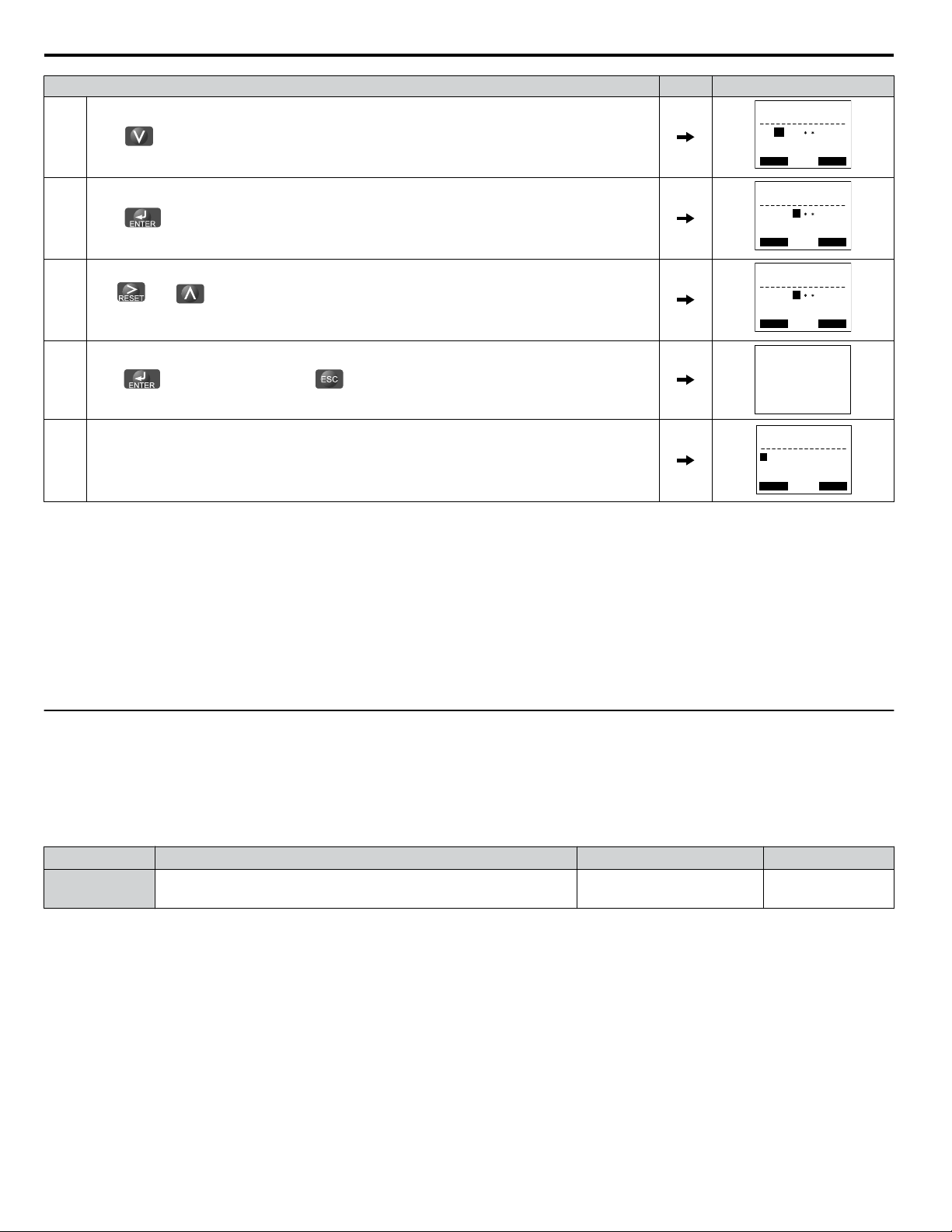
8.
9.
F1
Use
Press to save what was entered.
F2
,
, and to enter the password.
,
10. The display automatically returns to the display shown in step 6.
Table 1.3 Check if A1-02 is Locked (continuing from step 10 above)
Step Display/Result
1.
Press to display A1-02.
2.
Press , making sure that the setting values cannot be changed.
3.
Press to return to the first display.
Entry Accepted
- MODE - PRG
Programming
FWD
HELP
DATA
Table 1.4 Enter the Password to Unlock Parameters (continuing from step 3 above)
1.
Press to enter the parameter setup display.
2.
Press
3.
Press to scroll to A1-04 and .
F1
F2
,
to select the flashing digits as shown.
,
4. Enter the password “1234”.
5.
Press to save the new password.
Step Display/Result
Entry Accepted
Parameter Details
YASKAWA ELECTRIC SIEP C710636 10C Z1000U HVAC MATRIX Drive Programming Manual
6. Drive returns to the parameter display.
1
13
Page 14
← →
-PRMSET- PRG
Control Method
FWD
A1-02= 0
0
V/f Control
← →
-PRMSET- PRG
Control Method
FWD
A1-02=
0
V/f Control
0
← →
-PRMSET- PRG
Control Method
FWD
A1-02=
0
PM OpenLoop Vect
5
-PRMSETInitialization
Select Language
PRG
A1-00= 0
← →
FWD
1.1 A: Initialization
Step Display/Result
7.
Press
8.
Press
Use and to change the value if desired (though changing the control mode at this point is
9.
not typically done).
and scroll to A1-02.
to display the value set to A1-02. If the first “0” blinks, parameter settings are unlocked.
10.
Press to save the setting, or press to return to the previous display without saving changes.
Entry Accepted
11. The display automatically returns to the parameter display.
Note: 1. Parameter settings can be edited after entering the correct password.
2. Performing a 2-Wire or 3-Wire initialization resets the password to “0000”.
A1-06: Application Preset
n
Several Application Presets are available to facilitate drive setup for commonly used applications. Selecting one of these
Application
Presets
automatically assigns functions to the input and output terminals and sets a predefined group of parameters
to values appropriate for the selected application.
In addition, the parameters most likely to be changed are assigned to the group of User Parameters, A2-01 through A2-16.
User Parameters are part of the Setup Group, which provides quicker access by eliminating the need to scroll through multiple
menus.
u
A2: User Parameters
A2-01 to A2-32: User Parameters 1 to 32
n
The user can select up to 32 parameters and assign them to parameters A2-01 through A2-32 to provide quicker access by
eliminating the need to scroll through multiple menus. The User Parameter list can also save the most recently edited
parameters.
No. Parameter Name Setting Range Default
A2-01 to A2-32 User Parameters 1 to 32 A1-00 to S6-07
<1> This setting is the default setting of the Setup Mode parameters. Refer to TOEPC71063610 User Manual Section 4 for details.
<2> A1-06 determines how the setting of user parameters A2-01 through A2-32 are changed.
Determined by
A1-06
Saving User Parameters
To save specific parameters to A2-01 through A2-32, set parameter A1-01 to 2 to allow access to all parameters, then enter
the parameter number to one of the A2-oo
parameters to assign it to the list of User Parameters. Finally, set A1-01 to 1 to
restrict access so users can only set and refer to the parameters saved as User Parameters.
14
YASKAWA ELECTRIC SIEP C710636 10C Z1000U HVAC MATRIX Drive Programming Manual
<1>
<2>
Page 15

1.1 A: Initialization
A2-33: User Parameter Automatic Selection
n
Determines whether recently edited parameters are saved to the second half of the User Parameters (A2-17 to A2-32) for
quicker access.
No. Parameter Name Setting Range Default
A2-33 User Parameter Automatic Selection 0, 1
Setting 0: Do not save list of recently edited parameters
Determined by
A1-06
Set A2-33 to 0 to manually select the parameters listed in the User Parameter group.
Setting 1: Save list of recently edited parameters
Set A2-33 to 1 to automatically save recently edited parameters to A2-17 through A2-32. A total of 16 parameters are saved
with the most recently edited parameter set to A2-17, the second most recently to A2-18, and so on. Access the User Parameters
using the Setup Mode of the HOA keypad.
Note: User parameters are listed from A2-27 to A2-32. Parameters A2-01 to A2-26 are already listed as defined by default when in Setup Mode.
YASKAWA ELECTRIC SIEP C710636 10C Z1000U HVAC MATRIX Drive Programming Manual
Parameter Details
1
15
Page 16

Drive
A1 Analog Input 1
0 to 10 V
AC Analog input common
2 k
+V
10.5 V, 20 mA power supply
A2 Analog Input 2
A3 Analog Input 3
Drive
A1 Analog Input 1
AC Analog input common
+V
10.5 V, 20 mA power supply
A2 Analog Input 2
A3 Analog Input 3
4 k
-10 to 10 V
OR
Customer
+/- 10 V
Supply
+10 V
-10 V
Common
1.2 b: Application
1.2 b: Application
u
b1: Operation Mode Selection
b1-01: Frequency Reference Selection for AUTO Mode
n
Selects the frequency reference source 1.
Note: If a Run command is input to the drive, but the frequency reference entered is 0 or below the minimum frequency, the AUTO or HAND
Setting 0: HOA Keypad
Using this setting, the frequency reference can be input using the HOA keypad.
Setting 1: Terminals (analog input terminals)
Using
Voltage Input
Voltage input can be used at any of the three analog input terminals. Make the settings as described in Table 1.5 for the input
used.
Terminal Signal Level
A1
A2
A3
indicator LED on the HOA keypad will light and the OFF indicator will flash.
No. Parameter Name Setting Range Default
b1-01 Frequency Reference Selection for AUTO Mode 0 to 3 1
this setting, an analog frequency reference can be entered as a voltage or current signal from terminals A1, A2, or A3.
Table 1.5 Analog Input Settings for Frequency Reference Using Voltage Signals
Parameter Settings
Signal Level
Selection
0 to 10 Vdc H3-01 = 0
-10 to +10 Vdc H3-01 = 1
0 to 10 Vdc H3-09 = 0
-10 to +10 Vdc H3-09 = 1
0 to 10 Vdc H3-05 = 0
-10 to +10 Vdc H3-05 = 1
Function Selection Gain Bias
(Frequency Reference Bias)
H3-02 = 0
H3-10 = 0
(Frequency Reference Bias)
H3-06 = 0
(Frequency Reference Bias)
H3-03 H3-04 –
H3-11 H3-12
H3-07 H3-08
Set jumper S1 on the terminal
board to
Set DIP switch S4 on the
terminal board to “AI”.
Notes
“V” for voltage input.
Figure 1.1 Setting the Frequency Reference as a Voltage Signal at Terminal A1
Current Input
Input terminals, A1, A2, and A3 can accept a current input signal. Refer to Table 1.6 for an example to set terminal A2 for
current input.
Terminal
16
A2
Signal
Level
4 to 20 mA H3-09 = 2
0 to 20 mA H3-09 = 3
Table 1.6 Analog Input Settings for Frequency Reference Using a Current Signal
Signal Level
Selection
Function
Selection
H3-10 = 0
(Frequency Bias)
Parameter Settings
YASKAWA ELECTRIC SIEP C710636 10C Z1000U HVAC MATRIX Drive Programming Manual
Gain Bias
H3-11 H3-12
Notes
Make sure to set jumper S1 on the
terminal board to “I” for current
input.
Page 17

Drive
A1 Analog Input 1
0 or 4 to 20 mA
AC Analog input common
+V
10.5 V, 20 mA power supply
A2 Analog Input 2
A3 Analog Input 3
Jumper S1
A1/A2/A3
Voltage/Current
Selection
V
I
A1 A2 A3
1.2 b: Application
Figure 1.2 Setting the Frequency Reference as a Current Signal to Terminal A2
Switching between Main/Auxiliary Frequency References
The
frequency
reference input can be switched between the analog terminals A1, A2, and A3 using multi-speed inputs. Refer
to Multi-Step Speed Selection on page 52 for details on using this function.
Setting 2: Serial Communication (APOGEE FLN, BACnet, MEMOBUS/Modbus, Metasys N2)
This setting requires entering the frequency reference via the RS-422/RS-485 serial communications port (control terminals
R+, R-, S+, and S-). Refer to MEMOBUS/Modbus Configuration on page 280 for instructions.
Setting 3: Option card
This setting requires entering the frequency reference via an option board plugged into connector CN5-A on the drive control
board. Consult the option board manual for instructions on integrating the drive with the communication system.
Note: If the frequency reference source is set for Option PCB (b1-01 = 3), but an option board is not installed, an oPE05 operation error will be
b1-02: Run Command Selection for AUTO Mode
n
displayed on the digital operator and the drive will not run.
Determines the Run command selection for AUTO mode.
No. Parameter Name Setting Range Default
b1-02 Run Command Selection for AUTO Mode 1 to 3 1
Setting 1: Control Circuit Terminal
This setting requires entering the Run command via the digital input terminals using one of following sequences:
• 2-Wire sequence 1:
Two inputs (FWD/Stop-REV/Stop). Set A1-03 to 2220 to initialize the drive and preset terminals S1 and S2 to these
functions. This is the default setting of the drive. Refer to
Setting 40, 41: Forward Run, Reverse Run Command for 2-
Wire Sequence on page 84.
• 2-Wire sequence 2:
Two inputs (Start/Stop-FWD/REV). Refer to Setting 42, 43: Run and Direction Command for 2-Wire Sequence 2 on
page 84.
• 3-Wire sequence:
Three inputs (Start-Stop-FWD/REV). Set A1-03 to 3330 to initialize the drive and preset terminals S1, S2, and S5 to these
functions. Refer to Setting 0: 3-Wire Sequence on page 79.
Setting 2: Serial Communication (APOGEE FLN, BACnet, MEMOBUS/Modbus, Metasys N2)
This setting requires entering the Run command via serial communications by connecting the RS-422/RS-485 serial
communication cable to control terminals R+, R-, S+, and S- on the terminal block. Refer to MEMOBUS/Modbus
Configuration on page 280 for instructions.
Setting 3: Option Card
This setting requires entering the Run command via the communication option board by plugging a communication option
board into the CN5 port on the control PCB. Refer to the option card manual for instructions on integrating the drive into the
communication system.
Note: If b1-02 is set to 3, but an option card is not installed in CN5, an oPE05 operation error will be displayed on the HOA keypad and the drive
YASKAWA ELECTRIC SIEP C710636 10C Z1000U HVAC MATRIX Drive Programming Manual
will not run.
Parameter Details
1
17
Page 18

1.2 b: Application
b1-03: Stopping Method Selection
n
Selects how the drive stops the motor when the Run command is removed or when a Stop command is entered.
No. Parameter Name Setting Range Default
b1-03 Stopping Method Selection 0 to 3 1
Setting 0: Ramp to Stop
When the Run command is removed, the drive will decelerate the motor to stop. The deceleration rate is determined by the
active deceleration time. The default deceleration time is set to parameter C1-02.
When the output frequency falls below the level set in parameter b2-01, the drive will start DC injection or Zero Speed Control
depending on the selected control mode.
Setting 1: Coast to Stop
When the Run command is removed, the drive will shut off its output and the motor will coast (uncontrolled deceleration) to
stop. The stopping time is determined by the inertia and the friction in the driven system.
Run
command
Output
frequency
ON OFF
Drive output is shut off
Motor speed
Figure 1.3 Coast to Stop
Note: After
stop is initiated, any subsequent Run command entered will be ignored until the minimum baseblock time (L2-03) has expired. Do
a
not enter Run command until it has come to a complete stop. Use DC Injection at Start (Refer to b2-03: DC Injection Braking Time at
Start on page 22) or Speed Search (Refer to b3: Speed Search on page 23) to restart the motor before it has completely stopped.
Setting 2: DC Injection Braking to Stop
When the Run command is removed, the drive will enter baseblock (turn off its output) for the minimum baseblock time
(L2-03). When the minimum baseblock time has expired, the drive will inject the amount DC current set in parameter b2-02
into the motor windings to brake the motor. The stopping time in DC Injection Braking to Stop is significantly faster compared
to Coast to Stop.
Note: This function is not available in OLV/PM control mode (A1-02 = 5).
Run
command
Output
frequency
Motor speed
ON OFF
DC Injection Braking
with the current set in
Motor coasts
b2-02
Minimum Baseblock
Time (
L2-03)
Figure 1.4 DC Injection Braking to Stop
DC Injection Braking time is determined by the value set to b2-04 and the output frequency at the time the Run command is
removed. It can be calculated by:
18
YASKAWA ELECTRIC SIEP C710636 10C Z1000U HVAC MATRIX Drive Programming Manual
Page 19

DC Injection brake time
(b2-04) x 10 x Output frequency
Max. output frequency (E1-04)
=
DC Injection braking time
Min output
frequency
100%
(Max output
frequency)
Output frequency
when Stop command
was entered
Run wait time t
Active deceleration time
Momentary Power Loss
Minimum Baseblock
Time (L2-03)
b2-04×10
b2-04
1.2 b: Application
10%
Output frequency when
Stop command was entered
100%
(Maximum output
frequency)
Figure 1.5 DC Injection Braking Time Depending on Output Frequency
Note: If an overcurrent (oC) fault occurs during DC Injection Braking to Stop, increase the momentary power loss minimum baseblock time
(L2-03) until the fault no longer occurs.
Setting 3: Coast with Timer
the
When
Run command is removed, the drive will turn off its output and the motor will coast to stop. The drive will not start
if a Run command is input before the time t (C1-02) has expired. Cycle the Run command that was activated during time t
after t has expired to start the drive.
The wait time t is
Run command
Output
frequency
determined by the output frequency when the Run command is removed and by the active deceleration time.
ON ON ONOFF OFF
Drive output shut off
Run wait time t
Figure 1.6 Coast with Timer
Figure 1.7 Run Wait Time Depending on Output Frequency
b1-04: Reverse Operation Selection
n
Enables and disables Reverse operation. For some applications, reverse motor rotation is not appropriate and may cause
problems (e.g., air handling units, pumps, etc.).
No. Parameter Name Setting Range Default
b1-04 Reverse Operation Selection 0, 1 1
YASKAWA ELECTRIC SIEP C710636 10C Z1000U HVAC MATRIX Drive Programming Manual
Parameter Details
1
19
Page 20

1.2 b: Application
Setting 0: Reverse Enabled
Possible to operate the motor in both forward and reverse directions.
Setting 1: Reverse Disabled
Drive disregards a Reverse run command or a negative frequency reference.
b1-06: Digital Input Reading
n
Defines how the digital inputs are read. The inputs are acted upon every 1 ms or 2 ms depending upon the setting.
No. Name Setting Range Default
b1-06 Digital Input Reading 0, 1 1
Setting 0: Read once (1 ms scan)
The state
of a digital input is read once. If the state has changed, the input command is immediately processed. With this setting
the drive responds more quickly to digital inputs, but a noisy signal could cause erroneous operation.
Setting 1: Read twice (2 ms scan)
The state of a digital input is read twice. The input command is processed only if the state does not change during the double
reading. This reading process is slower than the “Read once” process, but it is more resistant to noisy signals.
b1-08: Run Command Selection in Programming Mode
n
As a safety precaution, the drive will not normally respond to a Run command input when the HOA keypad is being used to
adjust parameters in Programming Mode (Verify Menu, Setup Mode, Parameter Settings Mode, and Auto-Tuning Mode). If
required by the application, set b1-08 to allow the drive to run while in Programming Mode.
No. Parameter Name Setting Range Default
b1-08 Run Command Selection in Programming Mode 0 to 2 0
Setting 0: Run Command Is Not Accepted in Programming Mode
A Run command is not accepted while the HOA keypad is in Programming Mode.
Setting 1: Run Command Is Accepted in Programming Mode
A Run command is accepted in any HOA keypad mode.
Setting 2: Prohibit Entering Programming Mode during Run
It is not possible to enter the Programming Mode as long as the drive output is active. The Programming Mode cannot be
displayed during Run.
b1-11: Drive Delay Time Setting
n
If a time is set to b1-11, the drive will delay executing a Run command until the set time has expired. During Drive Delay
Time execution, the HOA keypad will display “WrUn”. Both Alarm and Run indicators will blink while the drive waits to
execute the Run command.
No. Parameter Name Setting Range Default
b1-11 Drive Delay Time Setting 0 to 600 s 0
b1-14: Phase Order Selection
n
Sets the phase order for drive output terminals U/T1, V/T2, and W/T3.
Switching motor phases will reverse the direction of the motor.
No. Parameter Name Setting Range Default
b1-14 Phase Order Selection 0, 1 0
Setting 0: Standard
Setting 1: Switch Phase Order
The direction of the motor is reversed.
b1-17: Run Command at Power Up
n
Determines whether an external Run command that is active during power up will start the drive.
20
YASKAWA ELECTRIC SIEP C710636 10C Z1000U HVAC MATRIX Drive Programming Manual
Page 21

1.2 b: Application
No. Parameter Name Setting Range Default
b1-17 Run Command at Power Up 0, 1 1
Setting 0: Disregarded
A new Run command must be issued after power up. Cycle the Run command to start the drive.
Note: For safety reasons, the drive is initially programmed not to accept a Run command at power up (b1-17 = 0). If a Run command is issued at
Setting 1: Allowed
power up, the RUN indicator LED will flash quickly.
The motor will start immediately after a power up if a Run command is already enabled.
WARNING! Sudden Movement Hazard. If b1-17 is set to 1 and an external Run command is active during power up, the motor will begin
rotating as soon as the power is switched on. Proper precautions must be taken to ensure that the area around the motor is safe prior to
powering up the drive. Failure to comply may cause serious injury.
b1-24: Commercial Power Operation Switching Selection
n
When the output frequency matches the power supply frequency (60 Hz), the PWM switching operation stops and switches
to operation with a direct commercial power supply connection.
Note: 1. Switching can be enabled when an inductive motor is being driven in V/f or OLV control modes.
2. Current value may change when a switch is made.
3. Verify that the induction motor can be driven with the commercial power supply (e.g., the rated voltage and rated speed) prior to enabling
the commercial power switching selection.
No. Parameter Name Setting Range Default
b1-24 Commercial Power Switching Selection 0, 1 0
Setting 0: Disabled
A voltage will be output with PWM switching operation regardless of the output frequency.
Setting 1: Enabled
When the deviation between the output frequency and the power supply frequency is less than or equal to the commercial
power switching output frequency coincidence level (b1-26), the PWM switching operation stops and switches to operation
with a direct commercial power supply connection.
Operation with a direct commercial power supply continues until the deviation between the output frequency and the power
supply frequency is greater than or equal to the commercial power switching output frequency coincidence/non-coincidence
level (b1-25 + b1-26).
b1-25/b1-26: Commercial Power Supply Operation Cancellation Level/Switching Level
n
These parameters set the value in 0.1 Hz increments at which commercial power supply switching selection is enabled and
disabled.
Entering Eco Mode
When the deviation between the output frequency and the power supply frequency becomes equal to or less than the setting
values of b1-26, an output frequency coincidence condition exists. The drive will operate in commercial power switching
mode. If the drive will not switch to commercial power supply switching mode, set b1-26.
Exiting Eco Mode
When
the deviation between the output frequency and the power supply frequency becomes equal to or greater than the setting
value of b1-25 + b1-26, the drive will operate in PWM switching mode. If commercial power switching mode and PWM
switching mode are repeated frequently, increase the setting value of b1-25.
Note: The drive will not switch to commercial power switching mode when L3-06, Stall Prevention Level during Run, is exceeded and L3-05,
Stall Prevention Selection during Run, is enabled.
No. Parameter Name Setting Range Default
b1-25 Commercial Power Supply Operation Cancellation Level 0.4 to 6.0 Hz 1.0 Hz
b1-26 Commercial Power Supply Operation Switching Level 0.0 to 3.0 Hz 0.2 Hz
u
b2: DC Injection Braking
These parameters determine operation of the DC Injection Braking and Zero Speed Control features.
YASKAWA ELECTRIC SIEP C710636 10C Z1000U HVAC MATRIX Drive Programming Manual
Parameter Details
1
21
Page 22

1.2 b: Application
b2-01: Zero Speed Level (DC Injection Braking Start Frequency)
n
Active when “Ramp to Stop” is selected as the stopping method (b1-03 = 0).
No. Name Setting Range Default
b2-01 Zero Speed Level (DC Injection Braking Start Frequency) 0.0 to 10.0 Hz
Determined by
A1-02
The function triggered by parameter b2-01 depends on the control mode that has been selected.
V/f and OLV/PM (A1-02 = 0, 5)
For these control modes, parameter b2-01 sets the starting frequency for DC Injection Braking at Stop. When the output
frequency falls below the setting of b2-01, DC Injection Braking is enabled for the time set in parameter b2-04.
DC Injection
Braking
Time
b2-04
Output
frequency
Figure 1.8 DC Injection Braking at Stop for V/f
b2-01
Note: If
b2-02: DC Injection Braking Current
n
to the E1-09 value.
is set to a smaller value than E1-09 (Minimum Output Frequency), then DC Injection Braking will begin when the frequency falls
E1-09 Min. Frequency
b2-01 Zero Speed Level
Sets the DC Injection Braking current as a percentage of the drive rated current.
No. Name Setting Range Default
b2-02 DC Injection Braking Current 0 to 100% 50%
The level of DC Injection Braking current affects the strength of the magnetic field attempting to lock the motor shaft.
Increasing the
current level will increase the amount of heat generated by the motor windings. Do not set this parameter higher
than the level necessary to hold the motor shaft.
b2-03: DC Injection Braking Time at Start
n
Sets the time of DC Injection Braking at start. Used to stop a coasting motor before restarting it or to apply braking torque at
start. Disabled when set to 0.00 s.
No. Name Setting Range Default
b2-03 DC Injection Braking Time at Start 0.00 to 10.00 s 0.00 s
Note: Before starting an uncontrolled rotating motor (e.g., a fan motor driven by windmill effect), use DC Injection or Speed Search to stop the
b2-04: DC Injection Braking Time at Stop
n
Sets
the
motor or detect motor speed before starting it. Otherwise, motor stalling and other faults can occur.
time of DC Injection Braking at stop. Used to completely stop a motor with high inertia load after ramp down. Increase
the value if the motor still coasts by inertia after it should have stopped. Disabled when set to 0.00 s.
No. Name Setting Range Default
b2-04 DC Injection Braking Time at Stop 0.00 to 10.00 s 0.00 s
b2-09: Motor Pre-Heat Current 2
n
Determines the percentage of motor rated output current that will be used for the motor pre-heat function. This function can
be useful in applications where the motor sits for extended periods of time in humid conditions. Motor pre-heating can only
be initiated by closing a digital input programmed as a Motor Pre-Heat 2 (H1-oo = 50).
No. Name Setting Range Default
b2-09 Motor Pre-Heat Current 2 0 to 100% 5%
22
YASKAWA ELECTRIC SIEP C710636 10C Z1000U HVAC MATRIX Drive Programming Manual
Page 23

AC Power supply
Output frequency
Minimum Baseblock Time (L2-03)
b3-05
Run command
Output
frequency
Minimum Baseblock
Time (L2-03)
b3-05
1.2 b: Application
u
b3: Speed Search
The Speed Search function allows the drive to detect the speed of a rotating motor shaft that is driven by external forces and
start the motor operation directly from the detected speed without first stopping the machine.
Example: When a momentary loss of power occurs, the drive output shuts off and the motor coasts. When power returns, the
drive can find the speed of the coasting motor and restart it directly.
Enabling Speed Search for PM motors only requires setting parameter b3-01 to 1. The drive offers current detection and speed
estimation Speed Search for induction motors. Parameter b3-24 selects the speed search method for induction motors. Both
methods and relevant parameters are explained below.
Speed Search start timing differs depending on whether operation is after a momentary power loss (L2-01 = 1 or 2) or after
the Speed Search at start (b3-01 = 1). The operation timing of the Speed Search after a momentary power loss is shown in
Figure 1.9. The operation timing after the Speed Search at start is shown in Figure 1.10.
After restoring power, the Speed Search operation remains in baseblock status for at least the time set in b3-05. However,
Speed Search will not start if the time set in L2-03, Minimum Baseblock Time, does not pass after the power stops. When
induced voltage remains in the motor, the Speed Search operation starts after the time set in b3-05 without waiting for the time
set in L2-03.
When performing a speed search operation at start, the speed search operation will start after waiting for the longer of the
times set
Search operation starts after the time set in b3-05 without waiting for the time set in L2-03.
n
Current Detection Speed Search 2 is for use with IM motors. The current set in b3-31 is applied and the speed is detected
based
Speed Search. If the output current during the Speed Search operation is larger than the setting value of b3-32, reduce the
frequency for the deceleration time set in b3-03. After motor speed estimation is completed, the speed is accelerated or
decelerated to the frequency reference.
Figure 1.9 Timing Chart for Speed Search after Recovery from Momentary Power Loss
in b3-05 and L2-03 after the Run command input is received. When induced voltage remains in the motor, the Speed
Figure 1.10 Timing Chart for Speed Search at Start
Current Detection Speed Search 2 (b3-24 = 2)
the current flow to the motor. The speed then accelerates or decelerates to the frequency reference after completing
on
Parameter Details
1
YASKAWA ELECTRIC SIEP C710636 10C Z1000U HVAC MATRIX Drive Programming Manual
23
Page 24

1.2 b: Application
Speed Estimation Speed Search (b3-24 = 1)
n
A
Speed
Estimation Speed Search estimates the motor speed while the motor is coasting and then restarts operation. The speed
then accelerates or decelerates to the frequency reference after completing Speed Search.
This method can be used for a single induction motor connected to a drive. Do not use this method if the motor is one or more
frame size smaller than the drive, at motor speeds above 200 Hz, or when using a single drive to operate more than one motor.
Speed Search Activation
n
Speed Search can be activated using any of the methods 1 through 5 described below. Select the Speed Search type in parameter
b3-24 independent of the activation method.
Method 1. Automatically activate Speed Search with every Run command. Set b3-01, Speed Search Selection at Start, to 1
(Enabled). External Speed Search commands are ignored.
Method 2. Activate Speed Search using the digital input terminals.
Use the input functions for H1-oo in Table 1.7.
Table 1.7 Speed Search Activation by Digital Inputs
Setting Description b3-24 = 1 b3-24 = 2
61
62
External Search
Command 1
External Search
Command 2
Activate Speed Estimation
Speed Search
Closed: Activate Current Detection Speed Search from the
maximum output frequency (E1-04).
Closed: Activate Current Detection Speed Search from the
frequency reference.
To activate Speed Search by a digital input, the input must be set together with the Run command or the Run command must
be entered after giving the Speed Search command.
Method 3. After automatic fault restart.
When the number of maximum fault restarts in parameter L5-01 is set higher than 0, the drive will automatically perform
Speed Search as specified by b3-24 following a fault.
Method 4. After momentary power loss.
This mode
requires that the Power Loss Ride-Thru function is enabled during CPU operation (L2-01 = 1 or 2). Refer to L2-01:
Momentary Power Loss Operation Selection on page 109.
Method 5. After external baseblock is released.
The drive will resume the operation starting with Speed Search if the Run command is present and the output frequency is
above the minimum frequency when the Baseblock command (H1-oo = 8 or 9) is released.
Rotation Direction Detection Conditions for Backspin
n
Backspin occurs when the motor rotates in the opposite direction from the rotation direction command. Specify the speed
search direction when power is recovered after a momentary power loss in applications in which backspin can occur, such as
for an oil pump when backspin may occur due to the weight of the oil after a momentary power loss. The search starts from
the rotation direction specified in the direction command when the momentary power loss time is short. The search starts from
the opposite direction of the direction specified in the direction command when the momentary power loss time is long. The
rotation for the Speed Search is determined as follows:
[t] is the time from the momentary power loss to recovery.
• 0 ≤ t < b3-50: The search is started in the direction specified by the direction command.
• b3-50 ≥ t < b3-51: The motor is not restarted and the baseblock continues.
The search starts from the opposite direction of the direction command when the momentary power loss time exceeds the
setting value of b3-51.
• b3-51 ≤ t: The search is started in the direction opposite to the direction command.
Refer to b3-50/b3-51: Backspin Search Direction Judgment Time 1/2 on page 28 for details on the backspin direction
judgment time.
Note: 1. Set b3-50 to the required time to enable rotation direction detection for backspin.
2. When setting b3-50, be sure to also set the following parameters to the values specified. Setting these parameters to any other values
will trigger an oPE08 fault.
b3-50 ≤ b3-51
b3-14 = 0
b3-24 = 2
3. Backspin detection is not necessary with a PM motor.
24
YASKAWA ELECTRIC SIEP C710636 10C Z1000U HVAC MATRIX Drive Programming Manual
Page 25

1.2 b: Application
b3-01: Speed Search Selection at Start
n
Determines if Speed Search is automatically performed when a Run command is issued.
No. Parameter Name Setting Range Default
b3-01 Speed Search Selection at Start 0, 1
Setting 0: Disabled
Determined by
A1-02
This setting starts operating the drive at the minimum output frequency when the Run command is entered. If external Speed
Search 1 or 2 is already enabled by a digital input, the drive will start operating with Speed Search.
Setting 1: Enabled
This setting performs Speed Search when the Run command is entered. The drive begins running the motor after Speed Search
is complete.
b3-03: Speed Search Deceleration Time
n
Sets the output frequency reduction ramp used by the Current Injection Method of Speed Estimation (b3-24 = 1). The time
entered into b3-03 will be the time to decelerate from maximum frequency (E1-04) to minimum frequency (E1-09).
No. Name Setting Range Default
b3-03 Speed Search Deceleration Time 0.1 to 10.0 s 2.0 s
b3-04: V/f Gain during Speed Search (Speed Estimation Type)
n
During
Speed
Search, the output voltage calculated from the V/f pattern is multiplied with this value. Changing this value can
help reduce the output current during Speed Search.
No. Name Setting Range Default
b3-04 V/f Gain during Speed Search 10 to 100%
b3-05: Speed Search Delay Time
n
In
cases
where an output contactor is used between the drive and the motor, the contactor must be closed before Speed Search
Determined by
o2-04
can be performed. This parameter can be used to delay the Speed Search operation, giving the contactor enough time to close
completely.
No. Name Setting Range Default
b3-05 Speed Search Delay Time 0.0 to 100.0 s 0.2 s
b3-06: Output Current 1 during Speed Search (Speed Estimation Type)
n
Sets
the
current injected to the motor at the beginning of Speed Estimation Speed Search as a factor of the motor rated current
set in E2-01. If the motor speed is relatively slow when the drive starts to perform Speed Search after a long period of baseblock,
it may be helpful to increase the setting value. The output current during Speed Search is automatically limited by the drive
rated current.
No. Name Setting Range Default
b3-06 Output Current 1 during Speed Search 0.0 to 2.0
Determined by
o2-04
Note: Use Current Detection Speed Search if Speed Estimation is not working correctly even after adjusting b3-06.
b3-07: Output Current 2 during Speed Search (Speed Estimation Type)
n
Sets
amount of output current during Speed Estimation Speed Search as a coefficient for the no-load current (output current
the
during Speed Search is automatically limited by the drive rated current).
Increase this setting value in increments of 0.1 if the drive fails to perform Speed Estimation.
No. Name Setting Range Default
b3-07 Output Current 2 during Speed Search (Speed Estimation Type) 0.0 to 5.0 1.0
YASKAWA ELECTRIC SIEP C710636 10C Z1000U HVAC MATRIX Drive Programming Manual
Parameter Details
1
25
Page 26

1.2 b: Application
b3-08: Current Control Gain during Speed Search (Speed Estimation Type)
n
Sets the proportional gain for the current controller during Speed Search.
No. Name Setting Range Default
b3-08 Current Control Gain during Speed Search (Speed Estimation Type) 0.00 to 6.00
b3-09: Current Control Integral Time during Speed Search (Speed Estimation Type)
n
Determined by
A1-02 and o2-04
Sets the Integral Time for the current controller during Speed Search.
No. Name Setting Range Default
b3-09
b3-10: Speed Search Detection Compensation Gain (Speed Estimation Type)
n
Current Control Integral Time during Speed Search (Speed
Estimation Type)
0.0 to 1000.0 ms
Determined by
A1-02
Sets the gain for the detected motor speed of the Speed Estimation Speed Search. Increase the setting only if an overvoltage
fault occurs when the drive restarts the motor.
No. Name Setting Range Default
b3-10 Speed Search Detection Compensation Gain 1.00 to 1.20 1.05
b3-11: Speed Search Method Switching Level (Speed Estimation Type)
n
Within the type of the speed measurement, the search method can be switched automatically by the amount of remaining
voltage in the motor. This parameter sets the switching level. (200 V class at 100% = 200 V, and 400 V class at 100% = 400
V).
No. Name Setting Range Default
b3-11 Speed Search Method Switching Level (Speed Estimation Type) 0.5 to 100.0% 5.0%
b3-12: Minimum Current Detection Level during Speed Search
n
Sets the minimum current detection level during Speed Search. Increase this setting value in increments of 0.1 if the drive
fails to perform Speed Estimation.
No. Name Setting Range Default
b3-12 Minimum Current Detection Level during Speed Search 2.0 to 10.0
b3-14: Bi-Directional Speed Search Selection (Speed Estimation Type)
n
Determined by
o2-04
Sets how the drive determines the motor rotation direction when performing Speed Estimation Speed Search.
No. Parameter Name Setting Range Default
b3-14 Bi-Directional Speed Search Selection 0, 1 1
Setting 0: Disabled
The drive uses the frequency reference to determine the direction of motor rotation to restart the motor.
Setting 1: Enabled
The drive detects the motor rotation direction to restart the motor.
b3-17: Speed Search Restart Current Level (Speed Estimation Type)
n
Sets the current level at which Speed Estimation is restarted as a percentage of drive rated current to avoid overcurrent and
overvoltage problems since a large current can flow into the drive if the difference between the estimated frequency and the
actual motor speed is too big when performing Speed Estimation.
No. Name Setting Range Default
b3-17 Speed Search Restart Current Level 0 to 200% 150%
26
YASKAWA ELECTRIC SIEP C710636 10C Z1000U HVAC MATRIX Drive Programming Manual
Page 27

1.2 b: Application
b3-18: Speed Search Restart Detection Time (Speed Estimation Type)
n
Sets the time for which the current must be above the level set in b3-17 before restarting Speed Search.
No. Name Setting Range Default
b3-18 Speed Search Restart Detection Time 0.00 to 1.00 s 0.10 s
b3-19: Number of Speed Search Restarts (Speed Estimation Type)
n
Sets the number of times the drive should attempt to find the speed and restart the motor. If the number of restart attempts
exceeds the value set to b3-19, the SEr fault will occur and the drive will stop.
No. Name Setting Range Default
b3-19 Number of Speed Search Restarts 0 to 10 3
b3-24: Speed Search Method Selection
n
Sets the Speed Search method.
In V/f control mode, set this parameter to 2 (Current Detection Type Speed Search 2) when b3-50 is 0.1 or longer.
No. Parameter Name Setting Range Default
b3-24 Speed Search Method Selection 1, 2
Determined by
A1-02 and o2-04
Setting 1: Speed Estimation
Setting 2: Current Detection 2
Note: 1. Enable or disable Speed Search at start with b3-01 and Speed Search after momentary power loss with L2-01.
2. Refer to Current Detection Speed Search 2 (b3-24 = 2) on page 23 and Refer to Speed Estimation Speed Search (b3-24 = 1) on page
24 for details on the Speed Search direction.
b3-25: Speed Search Wait Time
n
Sets the wait time between Speed Search restarts. Increase the wait time if problems occur with overcurrent, overvoltage, or
if an SEr fault occurs.
No. Name Setting Range Default
b3-25 Speed Search Wait Time 0.0 to 30.0 s 0.5 s
b3-27: Start Speed Search Select
n
Selects a condition to activate Speed Search Selection at Start (b3-01) or External Speed Search Command 1 or 2 from the
multi-function input.
No. Name Setting Range Default
b3-27 Start Speed Search Select 0, 1 0
Setting 0: Triggered when a Run Command Is Issued (Normal)
Setting 1: Triggered when an External Baseblock Is Released
b3-29: Speed Search Induced Voltage Level
n
Lower
this value in small increments if changes are necessary. Setting this value too low will prevent the drive from performing
Speed Search. There is normally no need to change this parameter from the default value.
No. Name Setting Range Default
b3-29 Speed Search Induced Voltage Level 0 to 10% 10%
b3-31: Speed Search Operation Current Level 1 (Current Detection Type 2)
n
Sets
the
current level used to limit the output current during Current Detection Type Speed Search 2 as a ratio to E2-03, Motor
No-Load Current.
YASKAWA ELECTRIC SIEP C710636 10C Z1000U HVAC MATRIX Drive Programming Manual
Parameter Details
1
27
Page 28

1.2 b: Application
The current level is determined for a no-load current that is 30% of the rated motor current when the setting value of E2-03
is less than or equal to 30% of the rated motor current.
Note: If the setting value is too large, a stopped inductive motor may accelerate too quickly. In such cases, set this parameter to a value that is
b3-32: Speed Search Operation Current Level 2 (Current Detection 2)
n
Sets
the
smaller than the rated motor current.
No. Name Setting Range Default
b3-31
Speed Search Operation Current Level 1 (Current Detection Type
2)
1.50 to 3.50 1.50
current level at which to end the Speed Search for Current Detection Type Speed Search 2 as a ratio to E2-03, Motor
No-Load Current.
The current level is determined for a no-load current that is 30% of the rated motor current when the setting value of E2-03
is less than or equal to 30% of the rated motor current.
No. Name Setting Range Default
b3-32 Speed Search Operation Current Level 2 (Current Detection 2) 0.00 to 1.49 1.20
b3-33: Speed Search Selection when Run Command is Given during Uv
n
Activates
and
deactivates Speed Search at start in accordance with whether a Run command was issued during an undervoltage
(Uv) condition. Function is active when a momentary power loss (L2-01 = 1 or 2), Speed Search at start (b3-01 = 1), and
coasting to a stop (b1-03 = 1) are enabled.
No. Name Setting Range Default
b3-33 Speed Search Selection when Run Command is Given during Uv 0, 1 0
Setting 0: Disabled
Setting 1: Enabled
b3-50/b3-51: Backspin Search Direction Judgment Time 1/2
n
The direction of the Speed Search is adjusted to allow for backspin.
When
momentary power loss time t is shorter than the time set in b3-50, the search operates according to the direction command.
When momentary power loss time t is equal to or longer than the time set in b3-51, the search operates from the opposite
direction of the direction command. When momentary power loss time t is equal to or longer than the time set in b3-50 and
shorter than b3-15, baseblock continues until momentary power loss time t exceeds the time set in b3-51. The search then
operates from the opposite direction of the direction command.
Note: 1. Use these parameters only in applications in which backspin can occur
2. Be sure to set b3-50 > b3-51.
3. Backspin detection is not necessary with a PM motor.
No. Name Setting Range Default
b3-50 Backspin Search Direction Judgment Time 1 0.0 to 10.0
b3-51 Backspin Search Direction Judgment Time 2 0.0 to 10.0 0.0
Determined by
A1-02
Speed Search from the Direction Command (0.0 ≤ Momentary Power Loss Time t < b3-50)
When time t from the momentary power loss to recovery is shorter than the setting value of b3-50, Speed Search is performed
in the direction specified by the direction command. The deceleration time set in b3-52 is used for the search frequency and
the setting value of the frequency reference is used as the starting search frequency.
28
YASKAWA ELECTRIC SIEP C710636 10C Z1000U HVAC MATRIX Drive Programming Manual
Page 29

b3-52
Motor speed
Output frequency
Power supply voltage
0
Momentary power loss time t
Normal operation
Search in progress
b3-50
b3-51
Forward operation
t
Motor speed
Output frequency
Power supply voltage
0
Normal operation
Search in progress
b3-50
b3-51
b3-53
Forward operation
t
Momentary power loss time t
1.2 b: Application
Figure 1.11 Speed Search from Forward Run Command (0 ≤ t < b3-50)
Continuous Baseblock (b3-50 ≤ t < b3-51)
When time t from the momentary power loss to recovery is between the times set for b3-50 and b3-51, operation will not be
the baseblock will continue. The drive will stay in baseblock for the time set in b3-51 even after restoring power.
restarted
and
After the time set in b3-51 passes, Speed Search starts in the opposite direction of the direction command. The deceleration
time in b3-53 is used for the search frequency and the setting value of the frequency reference is used as the starting search
frequency.
Speed Search in Direction Opposite to Direction Command (b3-51 ≤ t)
When time t from the momentary power loss to recovery exceeds the setting value of b3-51, Speed Search is performed in the
opposite direction of the direction command. The deceleration time in b3-53 is used for the search frequency and the setting
value of the frequency reference is used as the starting search frequency.
YASKAWA ELECTRIC SIEP C710636 10C Z1000U HVAC MATRIX Drive Programming Manual
Figure 1.12 Continuous Baseblock (b3-50 ≤ t < b3-51)
Parameter Details
1
29
Page 30

Motor speed
Output frequency
Power supply voltage
0
Normal operation
Search in progress
b3-50
b3-51
Forward operation
t
Momentary power loss time t
b3-53
1.2 b: Application
Figure 1.13 Speed Search in Direction Opposite to Direction Command (b3-51 ≤ t)
b3-52: Backspin Search Deceleration Time 1
n
Sets the search frequency deceleration rate when searching from the direction command when momentary power loss time t
is shorter than the time set in b3-50.
Set the value lower than the motor deceleration rate during coasting.
No. Name Setting Range Default
b3-52 Backspin Search Deceleration Time 1 0.1 to 10.0 s 2.0 s
b3-53: Backspin Search Deceleration Time 2
n
Sets the search frequency deceleration rate for a Speed Search from the opposite direction of the direction command when
momentary power loss time t is equal to or longer than the time set in b3-51.
No. Name Setting Range Default
b3-53 Backspin Search Deceleration Time 2 0.1 to 10.0 s 2.0 s
u
b4: Timer Function
The timer
function is independent of drive operation and can delay the switching of a digital output triggered by a digital input
signal and help eliminate chattering switch noise from sensors. An on-delay and off-delay can be set separately.
To enable the timer function, set a multi-function input to “Timer Function Input” (H1-oo = 18) and set a multi-function
output to “Timer output” (H2-oo = 12). Only one timer can be used.
b4-01, b4-02: Timer Function On-Delay, Off-Delay Time
n
b4-01 sets the on-delay time for switching the timer output. b4-02 sets the off-delay time for switching the timer output.
No. Name Setting Range Default
b4-01 Timer Function On-Delay Time 0.0 to 3000.0 s 0.0 s
b4-02 Timer Function Off-Delay Time 0.0 to 3000.0 s 0.0 s
Timer Function Operation
n
The
switches off when the timer function input is open for longer than the value set to b4-02. Figure 1.14 illustrates the timer
function operation:
30
function switches on when the timer function input closes for longer than the value set to b4-01. The timer function
timer
YASKAWA ELECTRIC SIEP C710636 10C Z1000U HVAC MATRIX Drive Programming Manual
Page 31

b4-01 b4-02 b4-01 b4-02
Multi-function Contact
On (Closed)
Off (Open)
On (Closed)
Off (Open)
Multi-function Contact
Output: Timer Function
Input: Timer Function
ON ON
ON ON
(H1-□□=18)
(H2-□□=12)
ON
ON ON
ON
Internal data of H2-01
Multi-Function Digital
Outputs of H2-01
b4-03
b4-04
b4-03
On (Closed)
Off (Open)
On (Closed)
Off (Open)
b4-04
Time period that the multi- function
digital output is closed 100 ms
Time period that the multi-function
digital output is closed < 100 ms
Time period that the multi-function
digital output is closed = 100 ms
1.2 b: Application
Figure 1.14 Timer Operation
b4-03 to b4-08: H2-oo ON-Delay and OFF-Delay Time
n
Sets the length of the delay time for contact outputs to open or close for the related functions set in H2-oo.
No. Name Setting Range Default
b4-03 H2-01 ON Delay Time 0 to 65000 ms 0 ms
b4-04 H2-01 OFF Delay Time 0 to 65000 ms 0 ms
b4-05 H2-02 ON Delay Time 0 to 65000 ms 0 ms
b4-06 H2-02 OFF Delay Time 0 to 65000 ms 0 ms
b4-07 H2-03 ON Delay Time 0 to 65000 ms 0 ms
b4-08 H2-03 OFF Delay Time 0 to 65000 ms 0 ms
Note: The
u
b5: PID Control
The drive
and the feedback value to adjust the drive output frequency to minimize deviation and provide accurate closed loop control
of system variables such as pressure or temperature.
P Control
n
The output of P control is the product of the deviation and the P gain so that it follows the deviation directly and linearly. With
P control, only an offset between the target and feedback remains.
I Control
n
The output of I control is the integral of the deviation. It minimizes the offset between target and feedback value that typically
remains when pure P control is used. The integral time (I time) constant determines how fast the offset is eliminated.
D Control
n
D control predicts the deviation signal by multiplying its derivative (slope of the deviation) with a time constant, then adds
this value to the PID input. This way the D portion of a PID controller provides a braking action to the controller response and
can reduce the tendency to oscillate and overshoot.
D control tends to amplify noise on the deviation signal, which can result in control instability. Only use D control when
absolutely necessary.
PID Operation
n
To better demonstrate PID functionality, Figure 1.15 illustrates the PID output when the PID input (deviation) is at a constant
level.
YASKAWA ELECTRIC SIEP C710636 10C Z1000U HVAC MATRIX Drive Programming Manual
multi-function
digital output closes for at least 100 ms even when the length of the off-delay time and on-delay time for multi-function
digital output are each shorter than 100 ms,
has a built-in Proportional + Integral + Derivative (PID) controller that uses the difference between the target value
Parameter Details
1
31
Page 32

1.2 b: Application
PID input
Time
PID output
I control
D control
P control
Time
Using PID Control
n
PID Output
Figure 1.15 PID Operation
Applications for PID control are listed in Table 1.8.
Table 1.8 Using PID Control
Application Description Sensors Used
Speed Control
Pressure Maintains constant pressure using pressure feedback. Pressure sensor
Fluid Control Keeps flow at a constant level by feeding back flow data. Flow rate sensor
Temperature
Control
Machinery speed is fed back and adjusted to meet the target value. Synchronous control is
performed using speed data from other machinery as the target value
Maintains a constant temperature by controlling a fan with a thermostat.
Tachometer
Thermocoupler,
Thermistor
PID Setpoint Input Methods
n
The PID setpoint input can be input from one of the sources listed in Table 1.9.
If none of the sources listed in Table 1.9 are used, the frequency reference source in b1-01 (or b1-15) or one of the inputs
listed in Table 1.9 becomes the PID setpoint.
Table 1.9 PID Setpoint Sources
PID Setpoint Source Settings
Analog Input A1 Set H3-02 = C
Analog Input A2 Set H3-10 = C
Analog Input A3 Set H3-06 = C
MEMOBUS/Modbus Register 0006 H Set bit 1 in register 000F H to 1 and input the setpoint to register 0006 H
Pulse Input RP Set H6-01 = 2
Parameter b5-19 Set parameter b5-18 = 1 and input the PID setpoint to b5-19
Note: A duplicate allocation of the PID setpoint input will cause an oPE07 (Multi-Function Analog Input Selection Error) alarm.
PID Feedback Input Methods
n
Input
feedback signal for normal PID control or input two feedback signals can for controlling a differential process value.
one
Normal PID Feedback
Input the PID feedback signal from one of the sources listed in Table 1.10:
Table 1.10 PID Feedback Sources
PID Feedback Source Settings
Analog Input A1 Set H3-02 = B
Analog Input A2 Set H3-10 = B
Analog Input A3 Set H3-06 = B
Pulse Input RP Set H6-01 = 1
Note: A duplicate allocation of the PID feedback input will cause an oPE07 (Multi-Function Analog Input Selection Error) alarm.
32
YASKAWA ELECTRIC SIEP C710636 10C Z1000U HVAC MATRIX Drive Programming Manual
Page 33

1.2 b: Application
Differential Feedback
The second PID feedback signal for differential feedback can come from the sources listed in Table 1.11. The differential
feedback function is automatically enabled when a differential feedback input is assigned.
Table 1.11
PID Differential Feedback Sources
PID Differential Feedback Source Settings
Analog Input A1 Set H3-02 = 16 (Differential PID Feedback)
Analog Input A2 Set H3-10 = 16 (Differential PID Feedback)
Analog Input A3 Set H3-06 = 16 (Differential PID Feedback)
Note: A duplicate allocation of the PID differential feedback input will cause an oPE07 (Multi-Function Analog Input Selection Error) alarm.
YASKAWA ELECTRIC SIEP C710636 10C Z1000U HVAC MATRIX Drive Programming Manual
Parameter Details
1
33
Page 34

-
+
+
+
+
+
+
+
+
+
1
-1
+
+
+
-
Z
-1
+
-
+
+
+
+
+
Z
-1
-1
Z
-1
Frequency Reference 1 to 16
Frequency Reference
Selection 1/2
b1-01/15
Option Card
Serial Comm
Analog Input A1/A2/A3
Pulse Input
Output
Frequency
P
1/s
b5-08
1
2
3
PID Setpoint
(U5-04)
Proportional Gain
Setting (P)
b5-02
Integral Time
Setting (I)
b5-03
Integral Limit Setting
b5-04
PID Output
Limit/Lower Limit
b5-06 / b5-34
PID Delay
Time
PID disable when:
- b5-01=0
- a JOG Command is Input
- PID Disable by Digital Input Enabled
0
PID Integral Hold
H1-
=31
PID Integral
Reset
H1-
=30
PID Output
Level Selection
b5-09
Enable / Disable Reverse
Operation when PID
Output is Negative
0
1
0
1
0
1
0
PID Input
(U5-02)
PID Feedback
(U5-01)
b5-07
b5-10
PID Output
Gain Setting
PID Offset Adjustment
b5-15
PID Sleep Function Start Level
RUN
On/Off
b5-16
PID Sleep
Delay Timer
Sleep Function
SFS
C1-
4
d1-01 to d1-16
H6-01=1
b5-05
1 or 3
2 or 4
b5-01
Derivative
Time (D)
not B
b5-05
b5-01
2 or 4
1 or 3
not 1
H3-02/10=B
Analog Input A1/A2/A3
Pulse Input
0
PID Input Limit
b5-35
Disabled
Enabled
Analog Input A1/A2/A3
0
not 16
H3-02/10
= 16
PID Differential
Feedback
(U5-05)
PID Adjusted
Feedback
(U5-06)
PID Ouput
(U5-03)
Derivative
Time (D)
Upper Limit
Fmax x109%
Lower Limit
Fmax x109%
Lower Limit 0
b5-11
1
0
Upper Limit
Fmax x109%
Always 1 when
b5-01 = 3/4
PID Input
Level Selection
H1-
=35
not 1
b5-18 = 1
Rog, 0Fh, bit 1
H6-01 = 2
H3-02/06/10 = C
not C
not 2
0
1
b5-01
Analog Input A1/A2/A3
MEMOBUS Reg. 0006h
Pulse Input
b5-19
On
Off
PID Accel/Decel Time
b5-17
PID Soft Starter Cancel
(H1-
= 34)
0
3/4
1/2
1.2 b: Application
PID Block Diagram
n
Figure 1.16 PID Block Diagram
34
YASKAWA ELECTRIC SIEP C710636 10C Z1000U HVAC MATRIX Drive Programming Manual
Page 35

1.2 b: Application
b5-01: PID Function Setting
n
Enables or disables the PID operation and selects the PID operation mode.
No. Parameter Name Setting Range Default
b5-01 PID Function Setting 0, 1, 3 0
Setting 0: PID Disabled
Setting 1: Output Frequency = PID Output 1
The PID controller is enabled and the PID output builds the frequency reference.
Setting 3: Output Frequency = Frequency Reference + PID Output 1
The PID controller is enabled and the PID output is added to the frequency reference.
b5-02: Proportional Gain Setting (P)
n
Sets the P gain applied to the PID input. Larger values will tend to reduce the error but may cause oscillations if set too high,
while lower values may allow too much offset between the setpoint and feedback.
No. Name Setting Range Default
b5-02 Proportional Gain Setting (P) 0.00 to 25.00 2.00
b5-03: Integral Time Setting (I)
n
Sets the time constant used to calculate the integral of the PID input. The shorter the integral time set to b5-03, the faster the
offset will be eliminated. If the integral time is set too short, however, overshoot or oscillation may occur. To turn off the
integral time, set b5-03 to 0.00.
No. Name Setting Range Default
b5-03 Integral Time Setting (I) 0.0 to 360.0 s 1.0 s
b5-04: Integral Limit Setting
n
Sets the maximum output possible from the integral block as a percentage of the maximum frequency (E1-04).
No. Name Setting Range Default
b5-04 Integral Limit Setting 0.0 to 100.0% 100.0%
Note: On some applications, especially those with rapidly varying loads, the output of the PID function may show a fair amount of oscillation.
b5-05: Derivative Time (D)
n
Sets the time the drive predicts the PID input/PID feedback signal based on the derivative of the PID input/PID feedback.
Longer
controller responsiveness. D control is disabled by setting b5-05 to zero seconds.
b5-06: PID Output Limit
n
Sets the maximum output possible from the entire PID controller as a percentage of the maximum frequency (E1-04).
Program b5-04 to apply a limit to the integral output and suppress this oscillation.
settings improve the response but can cause instability, while shorter time settings reduce the overshoot but reduce
time
No. Name Setting Range Default
b5-05 Derivative Time (D) 0.00 to 10.00 s 0.00 s
No. Name Setting Range Default
b5-06 PID Output Limit 0.0 to 100.0% 100.0%
b5-07: PID Offset Adjustment
n
Sets the offset added to the PID controller output as a percentage of the maximum frequency (E1-04).
No. Name Setting Range Default
b5-07 PID Offset Adjustment -100.0 to 100.0% 0.0%
b5-08: PID Primary Delay Time Constant
n
Sets the time constant for the filter applied to the output of the PID controller. Normally, change is not required.
YASKAWA ELECTRIC SIEP C710636 10C Z1000U HVAC MATRIX Drive Programming Manual
Parameter Details
1
35
Page 36

1.2 b: Application
No. Name Setting Range Default
b5-08 PID Primary Delay Time Constant 0.00 to 10.00 s 0.00 s
Note: Useful when there is a fair amount of oscillation or when rigidity is low. Set to a value larger than the cycle of the resonant frequency.
b5-09: PID Output Level Selection
n
Reverses
Increasing this time constant may reduce the responsiveness of the drive.
sign of the PID controller output signal. Normally a positive PID input (feedback smaller than setpoint) leads to
the
positive PID output.
No. Parameter Name Setting Range Default
b5-09 PID Output Level Selection 0, 1 0
Setting 0: Normal Output
A positive PID input causes an increase in the PID output (direct acting).
Setting 1: Reverse Output
A positive PID input causes a decrease in the PID output (reverse acting).
b5-10: PID Output Gain Setting
n
Applies
a gain to the PID output and can be helpful when the PID function is used to trim the frequency reference (b5-01 = 3
or 4).
No. Name Setting Range Default
b5-10 PID Output Gain Setting 0.00 to 25.00 1.00
b5-11: PID Output Reverse Selection
n
Determines whether a negative PID output reverses the direction of drive operation. This parameter has no effect when the
PID function trims the frequency reference (b5-01 = 3 or 4) and the PID output will not be limited (same as b5-11 = 1).
No. Parameter Name Setting Range Default
b5-11 PID Output Reverse Selection 0, 1 0
Setting 0: Reverse Disabled
Negative PID output will be limited to 0 and the drive output will be stopped.
Setting 1: Reverse Enabled
Negative PID output will cause the drive to run in the opposite direction.
PID Feedback Loss Detection
n
The
PID feedback loss detection function detects broken sensors or broken sensor wiring. It should be used when PID control
is enabled to prevent critical machine conditions (e.g., acceleration to max. frequency) caused by a feedback loss.
Feedback loss can be detected in two ways:
• Feedback Low Detection
Detected when the feedback falls below a certain level for longer than the specified time. This function is set up using
parameters b5-12 to b5-14.
• Feedback High Detection
Detected when the feedback rises above a certain level for longer than the specified time. This function is set up using
parameters b5-12, b5-36, and b5-37.
The following figure illustrates the working principle of feedback loss detection when the feedback signal is too low. Feedback
high detection works in the same way.
36
YASKAWA ELECTRIC SIEP C710636 10C Z1000U HVAC MATRIX Drive Programming Manual
Page 37

1.2 b: Application
PID feedback value
PID
Feedback
Detection
Loss Level
(b5-13)
time
PID Feedback
Loss Detection Time
(b5-14)
Figure 1.17 PID Feedback Loss Detection
b5-12: PID Feedback Loss Detection Selection
n
no FbL
detection
PID Feedback
Loss Detection Time
(b5-14)
FbL detection
Enables or disables the feedback loss detection and sets the operation when a feedback loss is detected.
No. Parameter Name Setting Range Default
b5-12 PID Feedback Loss Detection Selection 0 to 5 0
Setting 0: Multi-Function Digital Outputs Only
Multi-function digital
outputs set for “PID feedback low” (H2-oo = 3E) will be triggered if the PID feedback value is below
the detection level set to b5-13 for the time set to b5-14 or longer. Multi-function digital outputs set for “PID feedback high”
(H2-oo = 3F) will be triggered if the PID feedback value is beyond the detection level set to b5-36 for longer than the time
set to b5-37. Neither a fault nor an alarm is displayed on the digital operator and the drive will continue operation. The multifunction digital outputs reset when the feedback value leaves the loss detection range.
Setting 1: Feedback Loss Alarm
If the PID feedback value falls below the level set to b5-13 for longer than the time set to b5-14, a “FBL - Feedback Low”
alarm will be displayed and a digital output set for “PID feedback low” (H2-oo = 3E) will be triggered. If the PID feedback
value exceeds the level set to b5-36 for longer than the time set to b5-37, a “FBH - Feedback High” alarm will be displayed
and a digital output set for “PID feedback high” (H2-oo = 3F) will be triggered. Both events trigger an alarm output
(H2-oo = 10). The drive will continue operation. The alarm and multi-function digital outputs reset when the feedback value
leaves the loss detection range.
Setting 2: Feedback Loss Fault
If the PID feedback value falls below the level set to b5-13 for longer than the time set to b5-14, a “FbL - Feedback Low”
fault will be displayed. If the PID feedback value exceeds the level set to b5-36 for longer than the time set to b5-37, a “FbH
- Feedback High” fault will be displayed. Both events trigger a fault output (H2-oo = E) and cause the drive to stop the
motor.
Setting 3: Digital Output Only, even if PID Is Disabled by Digital Input
Same as b5-12 = 0. Detection remains active when PID is disabled by a digital input (H1-oo = 19).
Setting 4: Feedback Loss Alarm, even if PID Is Disabled by Digital Input
Same as b5-12 = 1. Detection remains active when PID is disabled by a digital input (H1-oo = 19).
Setting 5: Feedback Loss fault, even if PID Is Disabled by Digital Input
Same as b5-12 = 2. Detection remains active when PID is disabled by a digital input (H1-oo = 19).
b5-13: PID Feedback Low Detection Level
n
Sets the PID feedback detection low level as a percentage of E1-04 (Maximum Output Frequency). The PID feedback must
fall below this level for longer than the time set to b5-14 before feedback loss is detected.
Parameter Details
No. Name Setting Range Default
b5-13 PID Feedback Low Detection Level 0 to 100% 0%
n
b5-14:
PID Feedback Low Detection Time
Sets the time that the PID feedback has to fall below b5-13 before feedback loss is detected.
YASKAWA ELECTRIC SIEP C710636 10C Z1000U HVAC MATRIX Drive Programming Manual
1
37
Page 38

1.2 b: Application
No. Name Setting Range Default
b5-14 PID Feedback Low Detection Time 0.0 to 25.5 s 1.0 s
PID Sleep
n
The PID Sleep function stops the drive when the PID output or the frequency reference falls below the PID Sleep operation
level
for
a certain time. The drive will resume operating when the PID output or frequency reference rise above the PID Sleep
operation level for the specified time. An example of PID Sleep operation appears in the figure below.
PID Output
PID Sleep Level ( b5-15)
Sleep Delay Time
Internal Run
command
External Run
command
During Run
Notes on using the PID Sleep function
b5-16 b5-16
Run
Figure 1.18 PID Sleep Operation
Stop
Continues to output “During Run”
Sleep Delay Time
Run command enabled
• The PID Sleep function is active even when PID control is disabled.
• The PID Sleep function stops the motor according to the stopping method set to b1-03.
The parameters necessary to control the PID Sleep function are explained below.
b5-15: PID Sleep Function Start Level
n
Sets the level that triggers PID Sleep.
The drive goes into Sleep mode if the PID output or frequency reference is smaller than b5-15 for longer than the time set to
b5-16. The drive resumes operation when the PID output or frequency reference is above b5-15 for longer than the time set
to b5-16.
No. Name Setting Range Default
b5-15 PID Sleep Function Start Level 0.0 to 400.0 Hz 0.0 Hz
b5-16: PID Sleep Delay Time
n
Sets the delay time to activate or deactivate the PID Sleep function.
No. Name Setting Range Default
b5-16 PID Sleep Delay Time 0.0 to 25.5 s 0.0 s
b5-17: PID Accel/Decel Time
n
The PID acceleration/deceleration time is applied on the PID setpoint value.
When the setpoint changes quickly, the normal C1-oo
acceleration times reduce the responsiveness of the system as they
are applied after the PID output. The PID accel/decel time helps avoid the hunting and overshoot and undershoot that can
result from the reduced responsiveness.
The PID acceleration/deceleration time can be canceled using a digital input programmed for “PID SFS cancel” (H1-oo =
34).
No. Name Setting Range Default
b5-17 PID Accel/Decel Time 0.0 to 6000.0 s 0.0 s
b5-18: PID Setpoint Selection
n
Enables or disables parameter b5-19 for PID setpoint.
No. Parameter Name Setting Range Default
b5-18 PID Setpoint Selection 0, 1 0
38
YASKAWA ELECTRIC SIEP C710636 10C Z1000U HVAC MATRIX Drive Programming Manual
Page 39

1.2 b: Application
Setting 0: Disabled
Parameter b5-19 is not used as the PID setpoint.
Setting 1: Enabled
Parameter b5-19 is used as PID setpoint.
b5-19: PID Setpoint Value
n
Used as the PID setpoint if parameter b5-18 = 1.
No. Name Setting Range Default
b5-19 PID Setpoint Value 0.00 to 100.00% 0.00%
b5-20: PID Setpoint Scaling
n
Determines
the units for the PID Setpoint Value (b5-19) and monitors U5-01 and U5-04. The units for setting and display can
be changed with b5-20.
No. Parameter Name Setting Range Default
b5-20 PID Setpoint Scaling 0 to 3 1
Setting 0: 0.01 Hz
The setpoint and PID monitors are displayed in Hz with a resolution of 0.01 Hz.
Setting 1: 0.01% (100.00%: Maximum PID Feedback)
The setpoint and PID monitors are displayed as a percentage with a resolution of 0.01%.
Setting 2: r/min (Set the Motor Poles)
The setpoint and PID monitors are displayed in r/min with a resolution of 1 r/min.
Setting 3: User Defined (Determined by b5-38 and b5-39)
Parameters b5-38 and b5-39 determine the units and resolution used to display the values the setpoint in b5-19, and PID
monitors U1-01 and U1-04.
b5-21: PID Sleep Input Source
n
Selects the Sleep Function characteristic action. When b5-21 is set to 1, the Sleep Function Start Level (b5-15) is compared
to the output of the drive (Speed Command after PID Block). Use this setting for open loop control.
The Sleep Function Start Level (b5-15) can be compared to the drive input or setpoint by setting b5-21 to 0.
When
b5-21 is set to 2, a variation of the Sleep Function called “Snooze” is enabled. See parameters b5-22 to b5-27 for details.
No. Parameter Name Setting Range Default
b5-21 PID Sleep Input Source 0 to 2 1
Setting 0: PID Setpoint
Setting 1: SFS Input
Setting 2: Snooze
b5-22: PID Snooze Level
n
Sets the PID Snooze function start level as a percentage of maximum frequency.
No. Parameter Name Setting Range Default
b5-22 PID Snooze Level 0 to 100% 0%
b5-23: PID Snooze Delay Time
n
Sets the PID Snooze function delay time in seconds.
No. Parameter Name Setting Range Default
b5-23 PID Snooze Delay Time 0 to 2600 s 0 s
YASKAWA ELECTRIC SIEP C710636 10C Z1000U HVAC MATRIX Drive Programming Manual
Parameter Details
1
39
Page 40

1.2 b: Application
b5-24: PID Snooze Deactivation Level
n
When the PID feedback drops below this level, normal operation starts again. Sets as a percentage of maximum frequency.
No. Parameter Name Setting Range Default
b5-24 PID Snooze Deactivation Level 0 to 100% 0%
b5-25: PID Setpoint Boost Setting
n
Temporary increase of PID setpoint to create an overshoot of the intended PID setpoint.
No. Parameter Name Setting Range Default
b5-25 PID Setpoint Boost Setting 0 to 100% 0%
b5-26: PID Maximum Boost Time
n
Associated
cannot be reached within the PID Maximum Boost Time (b5-26), the Setpoint Boost is interrupted and the Drive output is
turned off.
b5-27: PID Snooze Feedback Level
n
The second method of initiating the Snooze Function. The drive output shuts off when the PID feedback level exceeds the
PID Snooze Feedback Level (b5-27).
Normal
activates when both b5-22 and b5-27 conditions are met. There is no time delay for deactivation.
Sets as a percentage of maximum frequency.
b5-28: PID Feedback Function Selection
n
When b5-28 is set to 1, the square root of the PID feedback is compared to the PID Setpoint to determine appropriate drive
output to properly regulate the system.
This is helpful in cases where the measured feedback is pressure, but the PID loop needs to regulate flow.
with
the Snooze Function. In cases where the temporary PID Setpoint (intended PID setpoint + PID Setpoint Boost)
No. Parameter Name Setting Range Default
b5-26 PID Maximum Boost Time 0 to 2600 s 0 s
drive
and PID operation return after the PID feedback drops below the PID Snooze Deactivation Level (b5-24). Snooze
No. Parameter Name Setting Range Default
b5-27 PID Snooze Feedback Level 0 to 100% 60%
No. Parameter Name Setting Range Default
b5-28 PID Feedback Function Selection 0, 1 0
0: Disabled
1: Square Root
b5-29: PID Square Root Gain
n
A multiplier applied to the square root of the feedback. If the PID Function is regulating the flow of a closed loop system by
using a pressure feedback, it may be convenient to view the square root of the PID output using monitor U1-37.
No. Parameter Name Setting Range Default
b5-29 PID Square Root Gain 0.00 to 2.00 0.00
b5-30: PID Feedback Offset
n
Sets PID feedback Offset as a percentage of maximum frequency.
No. Parameter Name Setting Range Default
b5-30 PID Feedback Offset 0.00 to 100.00% 0.00%
40
YASKAWA ELECTRIC SIEP C710636 10C Z1000U HVAC MATRIX Drive Programming Manual
Page 41

1.2 b: Application
b5-34: PID Output Lower Limit
n
Sets
the minimum possible PID controller output as a percentage of the maximum output frequency (E1-04). The lower limit
is disabled when set to 0.00%
No. Name Setting Range Default
b5-34 PID Output Lower Limit -100.0 to 100.0% 0.00%
b5-35: PID Input Limit
n
Sets the maximum allowed PID input as a percentage of the maximum output frequency (E1-04). Parameter b5-35 acts as a
bipolar limit.
No. Name Setting Range Default
b5-35 PID Input Limit 0.0 to 1000.0% 1000.0%
b5-36: PID Feedback High Detection Level
n
Sets the excessive PID feedback detection high level as a percentage of E1-04 (Maximum Output Frequency). The PID
feedback must exceed this level for longer than the time set to b5-37 before feedback loss is detected.
No. Name Setting Range Default
b5-36 PID Feedback High Detection Level 0 to 100% 100%
b5-37: PID Feedback High Detection Time
n
Sets the time that the PID feedback must exceed the value set to b5-36 before feedback loss is detected.
No. Name Setting Range Default
b5-37 PID Feedback High Detection Time 0.0 to 25.5 s 1.0 s
b5-38, b5-39: PID Setpoint User Display, PID Setpoint Display Digits
n
When
parameter
feedback monitors (U5-01, U5-04).
Parameter b5-38 determines the display value when the maximum frequency is output and parameter b5-39 determines the
number of digits. The setting value is equal to the number of decimal places.
No. Name Setting Range Default
b5-38 PID Setpoint User Display 1 to 60000
b5-39 PID Setpoint Display Digits 0 to 3
Setting 0: No Decimal Places
Setting 1: One Decimal Place
Setting 2: Two Decimal Places
Setting 3: Three Decimal Places
b5-40: Frequency Reference Monitor Content During PID
n
Sets the content of the frequency reference monitor display (U1-01) when PID control is active.
No. Name Setting Range Default
b5-40 Frequency Reference Monitor Content During PID 0, 1 0
b5-20 is set to 3, parameters b5-38 and b5-39 set a user-defined display for the PID setpoint (b5-19) and PID
Determined by
b5-20
Determined by
b5-20
Setting 0: Frequency Reference after PID
Monitor U1-01 displays the frequency reference increased or reduced for the PID output.
Setting 1: Frequency Reference
Monitor U1-01 displays the frequency reference value.
b5-41: PID Unit Selection
n
Sets the display units in U5-14 and U5-15.
YASKAWA ELECTRIC SIEP C710636 10C Z1000U HVAC MATRIX Drive Programming Manual
Parameter Details
1
41
Page 42

1.2 b: Application
No. Name Setting Range Default
b5-41 PID Unit Selection 0 to 14 0
Setting 0: WC (Inch of Water)
Setting 1: PSI (Pounds per Square Inch)
Setting 2: GPM (Gallons per Minute)
Setting 3: F (Degrees Fahrenheit)
Setting 4: CFM (Cubic Feet per Minute)
Setting 5: CMH (Cubic Meters per Hour)
Setting 6: LPH (Liters per Hour)
Setting 7: LPS (Liters per Second)
Setting 8: Bar (Bar)
Setting 9: Pa (Pascal)
Setting 10: C (Degrees Celsius)
Setting 11: Mtr (Meters)
Setting 12: Ft (Feet)
Setting 13: LPM (Liters per Minute)
Setting 14: CMM (Cubic Meters per Minute)
b5-42: PID Output Monitor Calculation Method
n
No. Name Setting Range Default
b5-42 PID Output Monitor Calculation Method 0 to 3 0
Setting 0: Linear
The monitor displays PID output.
Setting 1: Square Root
The monitor displays square root PID output.
Setting 2: Quadratic
The monitor displays 1/(PID output)
Setting 3: Cubic
The monitor displays 1/(PID output)
b5-43/b5-44: PID Output 2 Monitor Max Upper/Lower 4 Digits
n
Set
the maximum monitor value at maximum frequency. U5-14 and U5-15 show Custom PID output. U5-14 shows the upper
2
3
4 digits and U5-15 shows the lower 4 digits. It shows 999999.99 maximum.
No. Name Setting Range Default
b5-43 Custom PID Output Monitor Setting 2 0 to 9999 0
b5-44 Custom PID Output Monitor Setting 2 0.00 to 99.99 0.00
b5-45: PID Output 2 Monitor Minimum
n
b5-14
shows
Custom PID Output. b5-45 sets the minimum display value at zero speed. This function is effective when b5-42
is set to 0 (Linear).
No. Name Setting Range Default
b5-45 PID Output 2 Monitor Minimum 0 to 999.9 999.9
b5-46: PID Setpoint Monitor Unit Selection
n
Sets the HOA keypad display units in U5-01 and U5-04 when b5-20 is set to 3.
No. Name Setting Range Default
b5-46 PID Setpoint Monitor Unit Selection 0 to 14 0
42
YASKAWA ELECTRIC SIEP C710636 10C Z1000U HVAC MATRIX Drive Programming Manual
Page 43

Response
Before adjustment
After adjustment
Time
1.2 b: Application
Setting 0: WC (Inch of Water)
Setting 1: PSI (Pounds per Square Inch)
Setting 2: GPM (Gallons per Minute)
Setting 3: F (Degrees Fahrenheit)
Setting 4: CFM (Cubic Feet per Minute)
Setting 5: CMH (Cubic Meters per Hour)
Setting 6: LPH (Liters per Hour)
Setting 7: LPS (Liters per Second)
Setting 8: Bar (Bar)
Setting 9: Pa (Pascal)
Setting 10: C (Degrees Celsius)
Setting 11: Mtr (Meters)
Setting 12: Ft (Feet)
Setting 13: LPM (Liters per Minute)
Setting 14: CMM (Cubic Meters per Minute)
b5-47: PID Output Reverse Selection 2
n
Determines whether a negative PID output reverses the direction of drive operation. When the PID function is used to trim
the frequency reference (b5-01 = 3 or 4), this parameter has no effect and the PID output will not be limited
(same as b5-11 = 1).
No. Name Setting Range Default
b5-47 PID Output Reverse Selection 2 0, 1 1
Setting 0: Reverse Disabled
Negative PID output will be limited to 0 and the drive output will be stopped.
Setting 1: Reverse Enabled
Negative PID output will cause the drive to run in the opposite direction.
Fine-Tuning PID
n
Follow the directions below to fine tune PID control parameters:
Table 1.12 PID Fine Tuning
Goal Tuning Procedure Result
Before adjustment
After adjustment
Suppress overshoot
• Reduce the derivative time (b5-05)
•
Increase the integral time (b5-03)
Response
Time
Achieve stability quickly while
allowing some overshoot
YASKAWA ELECTRIC SIEP C710636 10C Z1000U HVAC MATRIX Drive Programming Manual
• Decrease the integral time (b5-03)
• Increase the derivative time (b5-05)
Parameter Details
1
43
Page 44

Response
Before adjustment
After adjustment
Time
1.2 b: Application
Goal Tuning Procedure Result
Suppress long cycle oscillations
(longer than
Suppress short cycle oscillations
u
the integral time setting)
b8: Energy Saving
Increase the integral time (b5-03)
• If oscillation cycle time is close to the
derivative time, reduce the derivative
time (b5-05).
• If the
derivative time is set to 0.00 s and
oscillations are still a problem, reduce
the proportional gain (b5-02) or increase
the PID primary delay time (b5-08)
Response
Before adjustment
After adjustment
Time
The Energy Saving feature improves overall system operating efficiency by operating the motor at its most efficient level.
Note: 1. Energy Saving is not designed for applications that experience instantaneous heavy loads or applications that rarely operate with light
b8-01: Energy Saving Control Selection
n
load conditions.
2. Energy
3. The performance of the Energy Saving function depends on the accuracy of the motor data. Always perform Auto-Tuning and correctly
Saving is mainly designed for applications with variable torque, however Energy Saving is not appropriate for applications where
the load may suddenly increase.
enter the motor data before using this function.
Enables or disables the Energy Saving function.
Note: Enabling the Energy Saving function when using a PM motor may adversely affect motor efficiency depending on the type of PM motor.
Setting 0: Disabled
Setting 1: Enabled
b8-04: Energy Saving Coefficient Value (V/f)
n
Fine
Disable the Energy Saving function in such cases.
No. Parameter Name Setting Range Default
b8-01 Energy Saving Control Selection 0, 1
Energy Saving control. Adjust this setting while viewing the output power monitor (U1-08) and running the drive
tunes
Determined by
with a light load.
A low setting results in less output voltage and less energy consumption. If the value is set too low the motor may stall. The
default setting depends on the capacity of the drive.
No. Name Setting Range Default
b8-04 Energy Saving Coefficient Value 0.00 to 655.00
Note: The default value changes if the motor rated capacity set to E2-11 is changed. The Energy Saving coefficient is set automatically when
b8-05: Power Detection Filter Time (V/f)
n
Determines how often in milliseconds the output power is measured. The Energy Saving function continuously searches out
the lowest output voltage to achieve minimum output power.
Reducing
Auto-Tuning for Energy Saving is performed.
setting increases the response time. If the filter time is too short, the motor may become unstable with a lighter
this
Determined by
E2-11, and o2-04
load.
A1-02
44
YASKAWA ELECTRIC SIEP C710636 10C Z1000U HVAC MATRIX Drive Programming Manual
Page 45

1.2 b: Application
No. Name Setting Range Default
b8-05 Power Detection Filter Time 0 to 2000 ms 20 ms
b8-06: Search Operation Voltage Limit (V/f)
n
Sets the voltage limit for the Speed Search optimal output voltage detection as a percentage of the maximum output voltage.
The drive will keep the output voltage above this level during the search operation to prevent motor stalling.
Note: If set too low, the motor may stall when the load is suddenly increased. Disabled when set to 0. Setting this value to 0 does not disable
Energy Saving.
No. Name Setting Range Default
b8-06 Search Operation Voltage Limit 0 to 100% 0%
YASKAWA ELECTRIC SIEP C710636 10C Z1000U HVAC MATRIX Drive Programming Manual
Parameter Details
1
45
Page 46

Output
frequency
Accel Time 1
(C1-01)
Decel Time 1
(C1-02)
Accel Time 2
(C1-03)
Decel Time 2
(C1-04)
Decel Time 1
(C1-02)
FWD (REV)
Run command
ON
OFF
ON
ON
Accel/Decel Time Selection 1
(Terminals S1 to S7, H1-oo = “7”)
1.3 C: Tuning
1.3 C: Tuning
C parameters
set the characteristics for acceleration, deceleration, and S-curves. Other parameters in the C group cover settings
for slip compensation, torque compensation, and carrier frequency.
u
C1: Acceleration and Deceleration Times
C1-01 to C1-04: Accel, Decel Times 1 and 2
n
Four
different sets of acceleration and deceleration times can be set in the drive by digital inputs, motor selection, or switched
automatically.
Acceleration time parameters always set the time to accelerate from 0 Hz to the maximum output frequency (E1-04).
Deceleration time parameters always set the time to decelerate from maximum output frequency to 0 Hz. C1-01 and C1-02
are the default active accel/decel settings.
No. Parameter Name Setting Range Default
C1-01 Acceleration Time 1
C1-02 Deceleration Time 1
C1-03 Acceleration Time 2
0.1 to 6000.0 s 30.0 s
C1-04 Deceleration Time 2
Switching Acceleration Times by Digital Input
Accel/decel time 1 is active by default if no input is set.
Table 1.13
Accel/Decel Time Sel. 1
H1-oo = 7
0 C1-01 C1-02
1 C1-03 C1-04
Accel/Decel Time Selection by Digital Input
Active Times
Acceleration Deceleration
Figure 1.19 shows an operation example for changing accel/decel. times. The example below requires that the stopping method
be set for “Ramp to stop” (b1-03 = 0).
Figure 1.19 Timing Diagram of Accel/Decel Time Change
Switching Accel/Decel Times by a Frequency Level
The drive can switch between different acceleration and deceleration times automatically. The drive will switch from accel/
decel time 2 in C1-03 and C1-04 to the default accel/decel time in C1-01 and C1-02 when the output frequency exceeds the
frequency level set in parameter C1-11. When the frequency falls below this level, the accel/decel times are switched back.
Figure 1.20 shows an operation example.
Note: Acceleration
For example, if accel/decel time 2 is selected, the drive will use only accel/decel time 2; it will not switch from accel/decel time 2 to the
selected time.
and
deceleration times selected by digital inputs have priority over the automatic switching by the frequency level set to C1-11.
46
YASKAWA ELECTRIC SIEP C710636 10C Z1000U HVAC MATRIX Drive Programming Manual
Page 47

Output Frequency
C1-11
Accel/Decel Time
Switch Frequency
C1-03
setting
When the output frequency
C1-11, drive uses Accel/Decel Time 1 (C1-01, -02)
When the output frequency < C1-11, drive uses Accel/Decel Time 2 (C1-03, -04)
C1-01
setting
C1-02
setting
C1-04
setting
C1-03 =
(accel time from 0 Hz to C1-11) × (E1-04)
C1-11
C1-01 =
(accel time between C1-11 and E1-04) × (E1-04)
(E1-04 - C1-11)
C1-02 =
(decel time between E1-04 and C1-11) × (E1-04)
(E1-04 - C1-11)
C1-04 =
(decel time from C1-11 to 0 Hz) × (E1-04)
C1-11
1.3 C: Tuning
Figure 1.20 Accel/Decel Time Switching Frequency
C1-09: Fast Stop Time
n
Sets a special deceleration used when a select group of faults occur or when closing a digital input configured as H1-oo =
15 (N.O. input) or 17 (N.C. input). A momentary closure of the digital input will trigger the Fast Stop operation; it does not
have to be closed continuously.
The drive cannot be restarted after initiating a Fast Stop operation until after completing deceleration, clearing the Fast Stop
input, and cycling the Run command.
A digital output programmed for “During Fast Stop” (H2-oo = 4C) will be closed as long as Fast Stop is active.
No. Parameter Name Setting Range Default
C1-09 Fast Stop Time 0.1 to 6000.0 s 10.0 s
NOTICE: Rapid deceleration can trigger an overvoltage fault. The drive output shuts off when faulted and the motor coasts. Set an
appropriate Fast Stop time to C1-09 to avoid this uncontrolled motor state and to ensure that the motor stops quickly and safely.
C1-11: Accel/Decel Time Switching Frequency
n
the
Sets
frequency at which the drive switches between accel/decel time settings. See Refer to Switching Accel/Decel Times
by a Frequency Level on page 46.
No. Parameter Name Setting Range Default
C1-11 Accel/Decel Time Switching Frequency 0.0 to 400.0 Hz
Note: Setting C1-11 to 0.0 disables this function.
u
C2: S-Curve Characteristics
Determined by
A1-02
Use S-curve characteristics to smooth acceleration and deceleration and minimize abrupt shock to the load. Set S-curve
characteristic time during acceleration/deceleration at start and acceleration/deceleration at stop. Increase the value set to
C2-01 if the STo fault (Step Out Detection) occurs when starting a PM motor.
C2-01 and C2-02: S-Curve Characteristics
n
C2-01 and C2-02 set separate S-curves for each section of the acceleration or deceleration.
No. Parameter Name Setting Range Default
C2-01 S-Curve Characteristic at Accel Start
0.00 to 10.00 s
C2-02 S-Curve Characteristic at Accel End 0.20 s
Determined by
A1-02
Figure 1.21 illustrates S-curve application.
YASKAWA ELECTRIC SIEP C710636 10C Z1000U HVAC MATRIX Drive Programming Manual
Parameter Details
1
47
Page 48

C2-02
C2-01
0.20 s
<1>
0.20 s <1>
C2-02
C2-01
0.20 s <1>
0.20 s <1>
FWD run
REV run
Output
frequency
<1> S-Curve characteristic at Decel Start/End is fixed to 0.20 s.
1.3 C: Tuning
Figure 1.21 S-Curve Timing Diagram - FWD/REV Operation
Setting the S-curve will increase the acceleration and deceleration times.
Actual accel time = accel time setting + (C2-01 + C2-02) / 2
u
C4: Torque Compensation
The torque compensation function compensates for insufficient torque production at start-up or when a load is applied.
Note: Set the motor parameters and V/f pattern properly before setting torque compensation parameters.
C4-01: Torque Compensation Gain
n
Sets the gain for the torque compensation function.
No. Parameter Name Setting Range Default
C4-01 Torque Compensation Gain 0.00 to 2.50
Torque Compensation in V/f and OLV/PM:
drive
The
calculates the motor primary voltage loss using the output current and the termination resistor value (E2-05 for IM
Determined by
A1-02
motors, E5-05 for PM motors) and adjusts the output voltage to compensate insufficient torque at start or when load is applied.
The effects of this voltage compensation can be increased or decreased using parameter C4-01.
Adjustment
Although this parameter rarely needs to be changed, it may be necessary to adjust the torque compensation gain in small steps
of 0.05 in the following situations:
• Increase this setting when using a long motor cable.
• Decrease this setting when motor oscillation occurs.
Adjust C4-01 so the output current does not exceed the drive rated current.
Note: Refrain from adjusting this parameter in OLV/PM. Setting this value too high can cause overcompensation and motor oscillation.
C4-02: Torque Compensation Primary Delay Time
n
Sets the delay time used for applying torque compensation.
No. Parameter Name Setting Range Default
C4-02 Torque Compensation Primary Delay Time 0 to 60000 ms
Determined by
A1-02 and o2-04
Adjustment
Although C4-02 rarely needs to be changed, adjustments may be necessary in the following situations:
Increase this setting if the motor vibrates.
•
•
Decrease this setting if the motor responds too slowly to changes in the load.
48
YASKAWA ELECTRIC SIEP C710636 10C Z1000U HVAC MATRIX Drive Programming Manual
Page 49

1.3 C: Tuning
u
C6: Carrier Frequency
C6-02: Carrier Frequency Selection
n
Sets
the switching frequency of the drive output transistors. Changes to the switching frequency lower audible noise and reduce
leakage current.
Note: Increasing the carrier frequency above the default value automatically lowers the drive current rating. Refer to Rated Current Depending
Setting 1: 4.0 kHz
Setting 2: 6.0 kHz
Setting 3: 8.0 kHz
Setting 4: 10.0 kHz
Setting F: User defined (C6-03 to C6-05)
on Carrier Frequency on page 50.
No. Parameter Name Setting Range Default
C6-02 Carrier Frequency Selection 1 to 4, F Determined by A1-02 and o2-04.
Guidelines for Carrier Frequency Parameter Setup
Symptom Remedy
Speed and torque are unstable at low speeds
Noise from the drive affects peripheral devices
Excessive leakage current from the drive
Wiring between the drive and motor is too long
Audible motor noise is too loud Increase the carrier frequency.
<1> The carrier frequency may need to be lowered if the motor cable is too long. Refer to Table 1.14.
<1>
Lower the carrier frequency.
Table 1.14 Wiring Distance and Carrier Frequency
Wiring Distance Up to 50 m Greater than 50 m
Recommended setting value for C6-02 1 to 4 (up to 10 kHz) 1 (up to 4 kHz)
Note: The maximum cable length is 100 m when using OLV/PM (A1-02 = 5).
C6-03, C6-04, C6-05: Carrier Frequency Upper Limit, Lower Limit, Proportional Gain
n
Note: C6-04 and C6-05 are available in V/f Control mode only.
These parameters set a user-defined or a variable carrier frequency. Set C6-02 to F to set the upper and lower limits and the
carrier frequency proportional gain.
No. Parameter Name Setting Range Default
<1>
<1>
<1>
Determined by
C6-02 and o2-04
C6-03 Carrier Frequency Upper Limit
C6-04 Carrier Frequency Lower Limit (V/f Control only)
C6-05 Carrier Frequency Proportional Gain (V/f Control only)
<1> Available only when C6-02 is set to F.
4.0 to 10.0 kHz
4.0 to 10.0 kHz
0 to 99
The upper limit of the carrier frequency varies by the drive model. Refer to Rated Current Depending on Carrier
Frequency on page 50 for details.
Setting a Fixed User-Defined Carrier Frequency
A carrier frequency between the fixed selectable values can be entered in parameter C6-03 when C6-02 is set to F.
In V/f Control, adjust parameter C6-04 to the same value as C6-03.
Setting a Variable Carrier Frequency (V/f Control)
In V/f
Control, the carrier frequency can be set up to change linearly with the output frequency by setting the upper and lower
limits for the carrier frequency and the carrier frequency proportional gain (C6-03, C6-04, C6-05) as shown in Figure 1.22.
Parameter Details
1
YASKAWA ELECTRIC SIEP C710636 10C Z1000U HVAC MATRIX Drive Programming Manual
49
Page 50

1.3 C: Tuning
Carrier Frequency
C6-03
Output
x C6-05
C6-04
Figure 1.22 Carrier Frequency Changes Relative to Output Frequency
Note: When C6-05 is set lower than 7, C6-04 is disabled and the carrier frequency will be fixed to the value set in C6-03.
C6-09: Carrier Frequency during Rotational Auto-Tuning
n
Frequency
Output Frequency
E1-04
Max Output Frequency
Determines the carrier frequency while performing Rotational Auto-Tuning. Although this parameter rarely needs to be
changed, when overcurrent problems occur when Auto-Tuning a high frequency motor or low impedance motor, it may be
helpful to set C6-03 to a high value before setting C6-09 to 1.
No. Parameter Name Setting Range Default
C6-09 Carrier Frequency during Rotational Auto-Tuning 0, 1 0
Setting 0: Carrier frequency = 4 kHz
Setting 1: Same value set to C6-03
u
Rated Current Depending on Carrier Frequency
The tables below show the drive output current depending on the carrier frequency settings.
Use the data in the following tables to linearly calculate output current values for carrier frequencies not listed.
Table 1.15
Drive Model Setting Range
2o0028
2o0042
2o0054
2o0068
2o0081
2o0104
2o0130
2o0154
2o0192
2o0248
Drive Model Setting Range
4o0011
4o0014
4o0021
4o0027
4o0034
4o0040
4o0052
4o0065
4o0077
4o0096
4 to 10 kHz 28 25 22 20
4 to 10 kHz 42 38 34 29
4 to 10 kHz 54 49 43 38
4 to 10 kHz 68 61 54 48
4 to 10 kHz 81 73 65 57
4 to 8 kHz 104 94 83 —
4 to 8 kHz 130 117 104 —
4 to 6 kHz 154 139 — —
4 to 6 kHz 192 173 — —
Table 1.16 Three-Phase 400 V Class Carrier Frequency and Current Derating
4 to 10 kHz 11 9.9 8.8 7.7
4 to 10 kHz 14 13 11 9.8
4 to 10 kHz 21 19 17 15
4 to 10 kHz 27 24 22 19
4 to 10 kHz 34 31 27 24
4 to 10 kHz 40 36 32 28
4 to 10 kHz 52 47 42 36
4 to 10 kHz 65 59 52 46
4 to 10 kHz 77 69 62 54
4 to 8 kHz 96 86 77 —
Three-Phase 200 V Class Carrier Frequency and Current Derating
Rated Current [A]
4 kHz 6 kHz 8 kHz 10 kHz
4 kHz 248 — — —
Rated Current [A]
4 kHz 6 kHz 8 kHz 10 kHz
50
YASKAWA ELECTRIC SIEP C710636 10C Z1000U HVAC MATRIX Drive Programming Manual
Page 51

1.3 C: Tuning
Drive Model Setting Range
4o0124
4o0156
4o0180
4o0216
4o0240
4o0302
4o0361
4o0414
u
C7: Voltage Adjustment
C7-43: Input Voltage Offset Adjustment
n
Note: Adjustment is completed at the factory. Do not change the setting of this parameter.
4 to 8 kHz 124 112 99 —
4 to 6 kHz 156 140 — —
4 to 6 kHz 180 162 — —
4 kHz 216 — — —
4 kHz 240 — — —
4 kHz 302 — — —
4 kHz 361 — — —
4 kHz 414 — — —
4 kHz 6 kHz 8 kHz 10 kHz
Rated Current [A]
Enables adjustment of the offset for the input voltage circuit when the control board is replaced.
Changing the value of o2-04 will trigger an oPE30 error. The input voltage offset must be adjusted when the error occurs. If
the combination of the control board and drive does not change, set this parameter to 0002 (offset adjustment not required).
Contact Yaskawa or a Yaskawa representative if it becomes necessary to replace the control board.
No. Parameter Name Setting Range Default
C7-43 Input Voltage Offset Adjustment 0000 to 9999 0000
Setting 0000: Standard
Setting 0002: Offset Adjustment Not Required
C7-56: Power Factor Control Selection
n
Power factor control improves the input power supply power factor according to the operating conditions.
This parameter rarely requires adjustment, but may be enabled to improve the power factor in the low output region. Power
factor control is not suitable for applications with frequent load fluctuations.
This function is disabled in High Output Voltage Mode (C7-60 = 1).
No. Parameter Name Setting Range Default
C7-56 Power Factor Control Selection 0, 1 0
Setting 0: Power Factor Control Disabled
Setting 1: Power Factor Control Enabled
C7-60: Output Voltage Limit Mode Selection
n
Sets the mode to limit the output voltage.
Set
parameter to 0 (Harmonic suppression priority mode) to give priority to harmonic suppression. The maximum output
this
voltage is automatically limited to suppress harmonics.
Set this parameter to 1 (High output voltage mode) to give priority to the output voltage over harmonic suppression. The
effectiveness of harmonic suppression will be reduced because the maximum output voltage will be used.
No. Parameter Name Setting Range Default
C7-60 Output Voltage Limit Mode Selection 0, 1 1
Setting 0: Harmonic Suppression Priority Mode
Setting 1: High Output Voltage Mode
YASKAWA ELECTRIC SIEP C710636 10C Z1000U HVAC MATRIX Drive Programming Manual
Parameter Details
1
51
Page 52

=4
=0
=1
=2
=3
b1-01
(Freq.Reference Source1)
S5-05
d1-16
Terminal A1/A2
b1-01
(Freq.Reference Source1)
S5-01
(HAND Fref Source)
Terminal A1/A2
MEMOBUS/Modbus
Comm.
Option Card
d1-01
(Freq.Ref.1)
=3
=2
=1
=0
b1-01
(Freq.Reference Source1)
d1-17
d1-17
HOA Keypad (d1-01)
HOA Keypad (d1-04)
HOA Keypad (d1-03)
HOA Keypad (d1-02)
Terminal A1/A2
MEMOBUS/Modbus Comm.
Option Card
=0
=1
=2
=6
Frequency Reference
Terminal A1/A2
MEMOBUS/Modbus
Comm.
Option Card
d1-01
(Freq.Ref.1)
=3
=2
=1
=0
AUTO,OFF
HAND
d2-03
(Freq.Ref.Lower Limit)
Multi-Step Speed
Set by b1-01
0
0
1
1
NetRef
ComRef
d2-03
(Freq.Ref.Lower Limit)
Multi-Step Speed
S5-01<4
& HAND
JOG
EmergencyOverride
: OFF
=3
=4
=5
Sequence Timer Operation Enable
OFF when using
Option Card
1.4 d: Reference Settings
1.4 d: Reference Settings
Figure 1.23 gives an overview of the reference input, selections, and priorities.
Figure 1.23 Frequency Reference Setting Hierarchy
u
d1: Frequency Reference
d1-01 to d1-04, d1-16, and d1-17: Frequency References 1 to 4, 16, and Jog Frequency
n
Reference
The drive lets the user switch between up to 5 preset frequency references during run (including the Jog reference) through
the digital input terminals. The drive uses the acceleration and deceleration times that have been selected when switching
between each frequency reference.
The Jog Frequency overrides all other frequency references and must be selected by a separate digital input.
The multi-speed references 1 and 2 can be provided by analog inputs.
No. Parameter Name Setting Range Default
d1-01 to d1-04 Frequency Reference 1 to 4
d1-16 Frequency Reference 16
d1-17 Jog Frequency Reference
<1> The upper limit is determined by the maximum output frequency (E1-04) and upper limit for the frequency reference (d2-01).
<2> Setting units are determined by parameter o1-03. The default is “Hz” (o1-03 = 0).
Multi-Step Speed Selection
To use several speed references for a multi-step speed sequence, set the H1-oo parameters to 3 and 4. To assign the Jog
reference to a digital input, set H1-oo to 6.
Notes on using analog inputs as Multi-Speed 1 and 2:
The first frequency reference (Multi-Speed 1) comes from the source specified in b1-01. When using an analog input terminal
•
to supply the frequency reference, assign the frequency reference source to the control terminals (b1-01 = 1).
• When an analog input is set to “Auxiliary frequency 1” (H3-02 or H2-06 = 2), the value set to this input will be used as the
Select the different speed references as shown in Table 1.17. Figure 1.24 illustrates the multi-step speed selection.
52
Multi-Step Speed 2 instead of the value set to parameter d1-02. If no analog inputs are set for “Auxiliary frequency 1”, then
d1-02 becomes the reference for Multi-Step Speed 2.
YASKAWA ELECTRIC SIEP C710636 10C Z1000U HVAC MATRIX Drive Programming Manual
0.00 to 400.00 Hz
0.00 to 400.00 Hz
0.00 to 400.00 Hz
<1> <2>
<1> <2>
<1> <2>
0.00 Hz
0.00 Hz
6.00 Hz
<2>
<2>
<2>
Page 53

Table 1.17 Multi-Step Speed Reference and Terminal Switch Combinations
d1-04
d1-17
ON
ON
ON
ON
ON
Multi-step Speed Ref. 2
Jog Reference
Time
Multi-step Speed Ref. 1
Frequency
reference
d1-01
(A1)
d1-02
(A2)
d1-03
FWD (REV) Run/Stop
Reference
Frequency Reference 1 (set in b1-01) OFF OFF OFF
Frequency Reference 2
(d1-02 or input terminal A1, A2)
Frequency Reference 3
(d1-03 or input terminal A1, A2)
Frequency Reference 4 (d1-04) ON ON OFF
Jog Frequency Reference (d1-17)
<1> The Jog frequency overrides all other frequency references.
<1>
1.4 d: Reference Settings
Multi-Step Speed
H1-oo = 3
ON OFF OFF
OFF ON OFF
− − ON
Multi-Step Speed 2
H1-oo = 4
Jog Reference
H1-oo = 6
Figure 1.24 Preset Reference Timing Diagram
u
d2: Frequency Upper/Lower Limits
Upper and lower frequency limits prevent motor speed from going above or below levels that may cause resonance or
equipment damage.
d2-01: Frequency Reference Upper Limit
n
Sets
the
maximum frequency reference as a percentage of the maximum output frequency. This limit applies to all frequency
references.
Even if the frequency reference is set to a higher value, the drive internal frequency reference will not exceed this value.
No. Parameter Name Setting Range Default
d2-01 Frequency Reference Upper Limit 0.0 to 110.0% 100.0%
d2-02: Frequency Reference Lower Limit
n
Sets
the
minimum frequency reference as a percentage of the maximum output frequency. This limit applies to all frequency
references.
If a lower reference than this value is entered, the drive will run at the limit set to d2-02. If the drive is started with a lower
reference than d2-02, it will accelerate up to d2-02.
No. Parameter Name Setting Range Default
d2-02 Frequency Reference Lower Limit 0.0 to 110.0% 0.0%
Parameter Details
1
YASKAWA ELECTRIC SIEP C710636 10C Z1000U HVAC MATRIX Drive Programming Manual
53
Page 54

1.4 d: Reference Settings
Internal frequency
reference
d2-01
Operating
range
d2-02
Figure 1.25 Frequency Reference: Upper and Lower Limits
d2-03: Master Speed Reference Lower Limit
n
Frequency Reference Upper Limit
Frequency Reference Lower Limit
Set frequency reference
Sets a lower limit as a percentage of the maximum output frequency that will only affect a frequency reference entered from
the analog input terminals (A1, A2, or A3) as the master speed reference. This is unlike parameter d2-02, which affects all
frequency references regardless of their source.
Note: When lower limits are set to both parameters d2-02 and d2-03, the drive uses the greater of those two values as the lower limit.
No. Parameter Name Setting Range Default
d2-03 Master Speed Reference Lower Limit 0.0 to 110.0% 0.0%
u
d3: Jump Frequency
d3-01 to d3-04: Jump Frequencies 1, 2, 3 and Jump Frequency Width
n
Jump
frequencies
are frequency ranges at which the drive will not operate. The drive can be programmed with three separate
Jump Frequencies to avoid operating at speeds that cause resonance in driven machinery. If the speed reference falls within a
Jump Frequency dead band, the drive will clamp the frequency reference just below the dead band and only accelerate past it
when the frequency reference rises above the upper end of the dead band.
Setting parameters d3-01 through d3-03 to 0.0 Hz disables the Jump Frequency function.
No. Parameter Name Setting Range Default
d3-01 Jump Frequency 1 0.0 to 400.0 Hz 0.0 Hz
d3-02 Jump Frequency 2 0.0 to 400.0 Hz 0.0 Hz
d3-03 Jump Frequency 3 0.0 to 400.0 Hz 0.0 Hz
d3-04 Jump Frequency Width 0.0 to 20.0 Hz 1.0 Hz
Figure 1.26 shows the relationship between the Jump Frequency and the frequency reference.
54
YASKAWA ELECTRIC SIEP C710636 10C Z1000U HVAC MATRIX Drive Programming Manual
Page 55

Frequency
reference
Output
Frequency
Jump
Frequency
3
(d3-03)
Jump
Frequency
2
(d3-02)
Jump
Frequency
1
(d3-01)
Frequency
reference
decreases
Frequency
reference
increases
d3-04 d3-04
d3-04 d3-04
d3-04 d3-04
Figure 1.26 Jump Frequency Operation
1.4 d: Reference Settings
Note: 1. The drive will use the active accel/decel time to pass through the specified dead band range, but will not allow continuous operation in
that range.
2. When setting more than one Jump Frequency, make sure that the parameters do not overlap.
u
d4: Frequency Reference Hold and Up/Down 2 Function
d4-01: Frequency Reference Hold Function Selection
n
This parameter is effective when either of the digital input functions listed below are used:
•
Accel/decel ramp hold function (H1-oo= A)
•
Up/Down function (H1-oo = 10 and 11)
No. Parameter Name Setting Range Default
d4-01 Frequency Reference Hold Function Selection 0, 1 0
The operation depends on the function used with parameter d4-01.
Setting 0: Disabled
• Acceleration hold
The hold value will be reset to 0 Hz when the Stop command is entered or the drive power is switched off. The active
frequency reference will be the value the drive uses when it restarts.
•
Up/Down
The frequency reference value will be reset to 0 Hz when the Stop command is entered or the drive power is switched off.
The drive will start from 0 Hz when it is restarted.
Setting 1: Enabled
• Acceleration hold
The last hold value will be saved when the Run command or the drive power is switched off and the drive will use the saved
value as the frequency reference when it restarts. Make sure to continuously enable the multi-function input terminal set for
“Accel/decel ramp hold” (H1-oo = A) or the hold value will be cleared when the power is switched on.
Parameter Details
1
YASKAWA ELECTRIC SIEP C710636 10C Z1000U HVAC MATRIX Drive Programming Manual
55
Page 56

1.4 d: Reference Settings
Power supply
Forward Run / Stop
Hold Accel/Decel
Frequency reference
Output frequency
Figure 1.27 Frequency Reference Hold with Accel/Decel Hold Function
ON
OFF OFF
ON ON
Hold Hold
ON ON
OFF
OFFOFF
ON
d4-01 = 1
d4-01 = 0
• Up/Down
The frequency reference value will be saved when the Run command or the drive power is switched off. The drive will use
the frequency reference that was saved when it restarts.
Clearing the Saved Value
Depending on which function is used, it is possible to clear the saved frequency reference value by:
• Releasing the input programmed for Acceleration hold.
• Setting an Up or Down command while no Run command is active.
d4-10: Up/Down Frequency Reference Limit Selection
n
Selects how the lower frequency limit is set when using the Up/Down function. Refer to Settings 10 and 11: Up/Down
Function on page 80 for details on the Up/Down function in combination with frequency reference limits.
No. Parameter Name Setting Range Default
d4-10 Up/Down Frequency Reference Limit Selection 0, 1 0
Setting 0: Lower Limit is Determined by d2-02 or Analog Input
The lower frequency reference limit is determined by the higher value of either parameter d2-02 or an analog input (A1, and
A2) that is programmed for “Frequency bias”.
Note:
Setting 1: Lower Limit is Determined by Parameter d2-02
example,
For
input as the reference source, the analog value becomes the lower reference limit when the Up/Down command is active. Change d4-10 to
1 to make the Up/Down function independent of the analog input value.
if the command to switch the external reference (H1-oo = 2) is used to switch between the Up/Down function and an analog
Only parameter d2-02 sets the lower frequency reference limit.
u
d6: Field Weakening
d6-01: Field Weakening Level
n
Sets
drive output voltage for the Field Weakening function as a percentage of the maximum output voltage. Enabled when
the
a multi-function input is set for Field Weakening (H1-oo = 63).
No. Parameter Name Setting Range Default
d6-01 Field Weakening Level 0 to 100% 80%
n
d6-02:
Field Weakening Frequency Limit
Sets the minimum output frequency at which field weakening can be activated. Field Weakening cannot be activated for
frequencies below d6-02.
No. Parameter Name Setting Range Default
d6-02 Field Weakening Frequency Limit 0 to 400.0 Hz 0.0 Hz
56
YASKAWA ELECTRIC SIEP C710636 10C Z1000U HVAC MATRIX Drive Programming Manual
Page 57

1.4 d: Reference Settings
u
d7: Offset Frequency
d7-01 to d7-03: Offset Frequency 1 to 3
n
Three different offset values can be added to the frequency reference. They can be selected using digital inputs programmed
for Offset frequency 1, 2, and 3 (H1-oo = 44, 45, 46). The selected offset values are added together if multiple inputs are
closed simultaneously.
No. Parameter Name Setting Range Default
d7-01 Offset Frequency 1 -100.0 to 100.0% 0%
d7-02 Offset Frequency 2 -100.0 to 100.0% 0%
d7-03 Offset Frequency 3 -100.0 to 100.0% 0%
Figure 1.28 illustrates the Offset frequency function.
Frequency
reference
Offset Frequency 1 [d7-01]
Offset Frequency 2 [d7-02]
(Signed)
(Signed)
Multi-function
input (44) = on
Multi-function
input (45) = on
SFS
Frequency
reference after
soft starter
Offset Frequency 3 [d7-03]
(Signed)
Figure 1.28 Offset Frequency Operation
Multi-function
input (46) = on
YASKAWA ELECTRIC SIEP C710636 10C Z1000U HVAC MATRIX Drive Programming Manual
Parameter Details
1
57
Page 58

1.5 E: Motor Parameters
1.5 E: Motor Parameters
E parameters cover V/f pattern and motor data settings.
u
E1: V/f Pattern for Motor 1
V/f Pattern Settings (E1-03)
n
The
drive uses a V/f pattern to adjust the output voltage relative to the frequency reference. There are 15 different predefined
V/f patterns (setting 0 to E) from which to select, each with varying voltage profiles, saturation levels (frequency at which
maximum voltage is reached), and maximum frequencies. Additionally, one custom V/f pattern is available (setting F) that
requires the user to create the pattern using parameters E1-04 through E1-10.
E1-03: V/f Pattern Selection
n
Selects the V/f pattern for the drive and motor from 15 predefined patterns or creates a custom V/f pattern.
No. Parameter Name Setting Range Default
E1-03 V/f Pattern Selection
<1> Settings 0 through E are not available in OLV/PM (A1-02 = 5).
<2> Parameter is not reset to the default value when the drive is initialized using A1-03.
0 to F
<1>
Setting a Predefined V/f Pattern (Setting 0 to E)
Choose the V/f pattern that best meets the application demands from Table 1.18. These settings are available only in
V/f Control modes. Set the correct value to E1-03. Parameters E1-04 to E1-13 can only be monitored, not changed.
Note:
Setting Specification Characteristic Application
<1>
<1> Setting F
1. Setting an improper V/f pattern may result in low motor torque or increased current due to overexcitation.
2. Drive initialization does not reset parameter E1-03.
Table 1.18 Predefined V/f Patterns
0 50 Hz
1 60 Hz
2 60 Hz (with 50 Hz base)
3 72 Hz (with 60 Hz base)
4 50 Hz, Variable torque 1
5 50 Hz, Variable torque 2
6 60 Hz, Variable torque 1
7 60 Hz, Variable torque 2
8 50 Hz, mid starting torque
9 50 Hz, high starting torque
A 60 Hz, mid starting torque
B 60 Hz, high starting torque
C 90 Hz (with 60 Hz base)
D 120 Hz (with 60 Hz base)
E 180 Hz (with 60 Hz base)
F
enables a custom V/f pattern by changing parameters E1-04 to E1-13. When the drive is shipped, the default values for parameters E1-04
to E1-13 are the same as those of setting 1.
60 Hz Constant torque
Constant torque
Variable torque
High starting torque
Constant output
For general purpose applications. Torque remains constant
regardless of changes to speed.
For fans, pumps, and other applications where the required
torque changes as a function of the speed.
Select high starting torque when:
• Wiring between the drive and motor exceeds 150 m.
A large amount of starting torque is required.
•
Output voltage is constant when operating at greater than
60 Hz.
For general purpose applications. Torque remains constant
regardless of changes to speed.
F
<2>
The following tables show details on predefined V/f patterns.
58
YASKAWA ELECTRIC SIEP C710636 10C Z1000U HVAC MATRIX Drive Programming Manual
Page 59

0
18
400
1.3 2.5 50
30
Voltage (V)
Frequency (Hz)
0
18
30
400
1.5 3 60
Voltage (V)
Frequency (Hz)
0
18
30
400
1.5 3 6050
Voltage (V)
Frequency (Hz)
0
18
30
400
1.5 3 7260
Voltage (V)
Frequency (Hz)
0
16
400
1.3 25 50
70
Voltage (V)
Frequency (Hz)
0
18
400
1.3 25 50
100
Voltage (V)
Frequency (Hz)
0
16
400
1.5 30 60
70
Voltage (V)
Frequency (Hz)
0
18
400
1.5 30 60
100
Voltage (V)
Frequency (Hz)
0
22
400
1.3 2.5 50
38
Voltage (V)
Frequency (Hz)
0
26
400
1.3 2.5 50
48
Voltage (V)
Frequency (Hz)
0
22
400
1.5 3 60
38
Voltage (V)
Frequency (Hz)
0
30
400
1.5 3 60
48
Voltage (V)
Frequency (Hz)
0
18
30
400
1.5 3 9060
Voltage (V)
Frequency (Hz)
0
18
30
400
1.5 3 12060
Voltage (V)
Frequency (Hz)
0
18
30
400
1.5 3 18060
Voltage (V)
Frequency (Hz)
0
18
30
400
1.5 3 60
Voltage (V)
Frequency (Hz)
1.5 E: Motor Parameters
Predefined V/f Patterns for Models 4o0011 and 4o0014
Table 1.19 Constant Torque Characteristics, Settings 0 to 3
Setting = 0 50 Hz Setting = 1 60 Hz Setting = 2 60 Hz Setting = 3 72 Hz
Table 1.20 Derated Torque Characteristics, Settings 4 to 7
Setting = 4 50 Hz Setting = 5 50 Hz Setting = 6 60 Hz Setting = 7 60 Hz
Table 1.21 High Starting Torque, Settings 8 to B
Setting = 8 50 Hz Setting = 9 50 Hz Setting = A 60 Hz Setting = B 60 Hz
Table 1.22 Rated Output Operation, Settings C to F
Setting = C 90 Hz Setting = D 120 Hz Setting = E 180 Hz Setting = F 60 Hz
Predefined V/f Patterns for Models 2o0028 to 2o0192 and 4o0021 to 4o0124
The values in the following graphs are specific to 200 V class drives. Double the values for 400 V class drives.
Table 1.23 Rated Torque Characteristics, Settings 0 to 3
Setting = 0 50 Hz Setting = 1 60 Hz Setting = 2 60 Hz Setting = 3 72 Hz
200
14
Voltage (V)
7
0
1.3 2.5 50
Frequency (Hz)
200
14
Voltage (V)
7
1.5 3 60
0
Frequency (Hz)
200
Voltage (V)
14
7
1.5 3 6050
0
Frequency (Hz)
200
14
Voltage (V)
7
0
1.5 3 7260
Frequency (Hz)
Parameter Details
1
YASKAWA ELECTRIC SIEP C710636 10C Z1000U HVAC MATRIX Drive Programming Manual
59
Page 60

1.5 E: Motor Parameters
Table 1.24 Derated Torque Characteristics, Settings 4 to 7
Setting = 4 50 Hz Setting = 5 50 Hz Setting = 6 60 Hz Setting = 7 60 Hz
200
200
200
200
35
Voltage (V)
6
0
1.3 25 50
Frequency (Hz)
50
Voltage (V)
7
0
1.3 25 50
Frequency (Hz)
35
Voltage (V)
6
0
1.5 30 60
Frequency (Hz)
50
Voltage (V)
7
0
1.5 30 60
Frequency (Hz)
Table 1.25 High Starting Torque, Settings 8 to B
Setting = 8 50 Hz Setting = 9 50 Hz Setting = A 60 Hz Setting = B 60 Hz
200
18
Voltage (V)
9
1.3 2.5 50
0
Frequency (Hz)
200
23
Voltage (V)
11
0
1.3 2.5 50
Frequency (Hz)
200
18
Voltage (V)
9
0
1.5 3 60
Frequency (Hz)
Table 1.26 Constant Output, Settings C to F
200
23
13
Voltage (V)
0
1.5 3 60
Frequency (Hz)
Setting = C 90 Hz Setting = D 120 Hz Setting = E 180 Hz Setting = F 60 Hz
200
Voltage (V)
14
7
0
1.5 3 9060
Frequency (Hz)
200
Voltage (V)
14
7
0
1.5 3 12060
Frequency (Hz)
200
Voltage (V)
14
7
0
1.5 3 18060
Frequency (Hz)
230
Voltage (V)
16.1
8.1
0
1.5 3 60
Frequency (Hz)
Predefined V/f Patterns for Models 2o0216 and 4o0156 to 4o0414
The values in the following graphs are specific to 200 V class drives. Double the values for 400 V class drives.
Table 1.27 Rated Torque Characteristics, Settings 0 to 3
Setting = 0 50 Hz Setting = 1 60 Hz Setting = 2 60 Hz Setting = 3 72 Hz
200
Voltage (V)
12
6
0
1.3 2.5 50
Frequency (Hz)
200
Voltage (V)
12
6
0
1.5 3 60
Frequency (Hz)
200
Voltage (V)
12
6
0
1.5 3 6050
Frequency (Hz)
Table 1.28 Derated Torque Characteristics, Settings 4 to 7
Setting = 4 50 Hz Setting = 5 50 Hz Setting = 6 60 Hz Setting = 7 60 Hz
200
Voltage (V)
35
5
0
1.3 25 50
Frequency (Hz)
200
50
Voltage (V)
6
0
1.3 25 50
Frequency (Hz)
200
Voltage (V)
35
5
0
1.5 30 60
Frequency (Hz)
200
Voltage (V)
12
6
0
1.5 3 7260
Frequency (Hz)
200
50
Voltage (V)
6
0
1.5 30 60
Frequency (Hz)
60
YASKAWA ELECTRIC SIEP C710636 10C Z1000U HVAC MATRIX Drive Programming Manual
Page 61

1.5 E: Motor Parameters
Table 1.29 High Starting Torque, Settings 8 to B
Setting = 8 50 Hz Setting = 9 50 Hz Setting = A 60 Hz Setting = B 60 Hz
200
200
200
200
Voltage (V)
15
7
0
1.3 2.5 50
Frequency (Hz)
20
Voltage (V)
9
0
1.3 2.5 50
Frequency (Hz)
Voltage (V)
15
7
0
1.5 3 60
Frequency (Hz)
20
Voltage (V)
11
0
1.5 3 60
Frequency (Hz)
Table 1.30 Constant Output, Settings C to F
Setting = C 90 Hz Setting = D 120 Hz Setting = E 180 Hz Setting = F 60 Hz
200
Voltage (V)
12
6
0
1.5 3 9060
Frequency (Hz)
200
Voltage (V)
12
6
0
1.5 3 12060
Frequency (Hz)
200
Voltage (V)
12
6
0
1.5 3 18060
Frequency (Hz)
230
Voltage (V)
13.8
6.9
0
1.5 3 60
Frequency (Hz)
Setting a Custom V/f Pattern (Setting F: Default)
Setting parameter E1-03 to F allows the user to set up a custom V/f pattern by changing parameters E1-04 to E1-13.
V/f Pattern Settings E1-04 to E1-13
n
If E1-03 is set to a preset V/f pattern (i.e., a value other than F), the user can monitor the V/f pattern in parameters E1-04
through E1-13. To create a new V/f pattern, set E1-03 to F. Refer to V/f Pattern on page 62 for an example custom V/f
pattern.
Note:
E1-11
E1-12
E1-13
<1> Default setting is determined by E5-01 in OLV/PM. When E5-01 is set to FFFFH, the setting range for E1-04 and E1-06 is 10.0 to 400.0 Hz and
<2> Default setting is dependent on parameters A1-02, Control Mode Selection, and o2-04, and Drive Model Selection.
<3>
<4> Values shown are specific to 200 V class drives. Double the value for 400 V class drives.
<5> Default setting is determined by parameter A1-02, Control Mode Selection.
<6> Parameter ignored when E1-11 (Motor 1 Mid Output Frequency 2) and E1-12 (Motor 1 Mid Output Frequency Voltage 2) are set to 0.0.
<7> The drive changes these settings when Auto-Tuning is performed.
<8> When Auto-Tuning is performed, E1-13 and E1-05 will be set to the same value.
Certain E1-oo parameters might not be visible depending on the control mode. Refer to Parameter List
on page 191
for details.
No. Parameter Name Setting Range Default
E1-04 Maximum Output Frequency
E1-05 Maximum Voltage
E1-06 Base Frequency
40.0 to 400.0 Hz
0.0 to 255.0 V
0.0 to [E1-04]
E1-07 Middle Output Frequency 0.0 to [E1-04]
E1-08 Middle Output Frequency Voltage
E1-09 Minimum Output Frequency
E1-10 Minimum Output Frequency Voltage
<6>
<6>
<8>
Middle Output Frequency 2 0.0 to [E1-04] 0.0 Hz
Middle Output Frequency Voltage 2
Base Voltage
0.0 to 255.0 V
0.0 to [E1-04]
0.0 to 255.0 V
0.0 to 255.0 V
0.0 to 255.0 V
<1> <2> <3>
<4> <2> <5>
<1> <2> <3> <5>
<2>
<4> <2>
<1> <2> <3> <5>
<4> <2>
<4>
<4>
0.0 V
0.0 V
the setting range for E1-09 is 0.0 to 400.0 Hz.
When using PM motors, the default setting is determined by the motor code set to E5-01.
<7>
<7>
Parameter Details
YASKAWA ELECTRIC SIEP C710636 10C Z1000U HVAC MATRIX Drive Programming Manual
1
61
Page 62

1.5 E: Motor Parameters
Output Voltage (V)
E1-05
E1-12
E1-13
E1-08
E1-10
E1-09 E1-07 E1-06 E1-11 E1-04
Frequency (Hz)
Figure 1.29 V/f Pattern
Note: 1. The following condition must be true when setting up the V/f pattern: E1-09 ≤ E1-07 < E1-06 ≤ E1-11 ≤ E1-04
2. To make the V/f pattern a straight line below E1-06, set E1-09 equal to E1-07. In this case the E1-08 setting is disregarded.
3. E1-03 is unaffected when the drive is initialized, but E1-04 through E1-13 return to their default values.
4. Only use E1-11, E1-12, and E1-13 to fine-tune the V/f pattern in the constant output range. These parameters rarely need to be changed.
u
E2: Motor 1 Parameters
These parameters contain the motor data needed for motor 1. Enter the motor data into these parameters when Auto-Tuning
cannot be performed.
Note:
The function for switching between two motors cannot be used with a PM motor. E2-oo parameters are hidden when OLV/PM control
mode is selected (A1-02 = 5).
E2-01: Motor Rated Current
n
Provides motor control, protects the motor, and calculates torque limits. Set E2-01 to the full load amps (FLA) stamped on
the
motor
nameplate. If Auto-Tuning completes successfully, the value entered to T1-04 will automatically be saved to E2-01.
No. Parameter Name Setting Range Default
E2-01 Motor Rated Current
<1> Display is in the following units:
2o0028, 2o0042, and 4o0011 to 4o0027: 0.01 A units
2o0054 to 2o0248 and 4o0034 to 4o0414: 0.1 A units
Note:
E2-02: Motor Rated Slip
n
Setting E2-01 ≤ E2-03 will trigger an oPE02 error. Set E2-03 correctly to prevent this error.
10% to 150% of the drive
rated current
<1>
Determined by
o2-04
Sets the motor rated slip in Hz to provide motor control, protect the motor, and calculate torque limits.
No. Parameter Name Setting Range Default
E2-02 Motor Rated Slip 0.00 to 20.00 Hz
Determined by
o2-04
If Auto-Tuning cannot be performed, calculate the motor rated slip using the information written on the motor nameplate and
the formula below:
E2-02 = f - (n × p)/120
(f: rated frequency (Hz), n: rated motor speed (r/min), p: number of motor poles)
E2-03: Motor No-Load Current
n
Set
no-load current for the motor in amperes when operating at the rated frequency and the no-load voltage. The drive sets
the
E2-03 during the Auto-Tuning process (Rotational Auto-Tuning and Stationary Auto-Tuning 2, 3). The motor no-load current
listed in the motor test report can also be entered to E2-03 manually. Contact the motor manufacturer to receive a copy of the
motor test report.
No. Parameter Name Setting Range Default
E2-03 Motor No-Load Current
<1> Display is in the following units:
2o0028, 2o0042, and 4o0011 to 4o0027: 0.01 A units
62
0.00 A to [E2-01]
YASKAWA ELECTRIC SIEP C710636 10C Z1000U HVAC MATRIX Drive Programming Manual
<1>
Determined by
o2-04
Page 63

1.5 E: Motor Parameters
2o0054 to 2o0248 and 4o0034 to 4o0414: 0.1 A units
E2-04: Number of Motor Poles
n
Set
the
number of motor poles to E2-04. If Auto-Tuning completes successfully, the value entered to T1-06 will automatically
be saved to E2-04.
No. Parameter Name Setting Range Default
E2-04 Number of Motor Poles 2 to 48 4
E2-05:Motor Line-to-Line Resistance
n
Sets
the
line-to-line resistance of the motor stator winding. If Auto-Tuning completes successfully, this value is automatically
calculated. Enter this value as line-to-line and not for each motor phase.
If Auto-Tuning is not possible, contact the motor manufacturer to find out the line-to-line resistance or measure it manually.
When using the manufacturer motor test report, calculate E2-05 by one of the formulas below:
• E-type insulation: Multiply 0.92 times the resistance value (Ω) listed on the test report at 75 °C (167 °F).
• B-type insulation: Multiply 0.92 times the resistance value (Ω) listed on the test report at 75 °C (167 °F).
• F-type insulation: Multiply 0.87 times the resistance value (Ω) listed on the test report at 115 °C (239 °F).
No. Parameter Name Setting Range Default
E2-05 Motor Line-to-Line Resistance 0.000 to 65.000 Ω
Determined by
o2-04
E2-10: Motor Iron Loss for Torque Compensation
n
Sets the motor iron loss in watts.
No. Parameter Name Setting Range Default
E2-10 Motor Iron Loss for Torque Compensation 0 to 65535 W
E2-11: Motor Rated Power
n
Determined by
o2-04
Sets the motor rated power in kW. If Auto-Tuning completes successfully, the value entered to T1-02 will automatically be
saved to E2-11.
No. Parameter Name Setting Range Default
E2-11 Motor Rated Power 0.00 to 650.00 kW
Setting Motor Parameters Manually
n
Determined by
o2-04
Follow the instructions below when setting motor-related parameters manually instead of Auto-Tuning. Refer to the motor
test report included with the motor to ensure the correct data is entered into the drive.
Set the Motor Rated Current
Enter the motor rated current listed on the nameplate of the motor to E2-01.
Set the Motor Rated Slip
Calculate
the
motor rated slip using the base speed listed on the motor nameplate. Refer to the formula below, then enter that
value to E2-02.
Motor rated slip = rated frequency [Hz] – base speed [r/min] × (no. of motor poles) / 120
Set the No-Load Current
Enter the no-load current at rated frequency and rated voltage to E2-03. This information is not usually listed on the nameplate.
Contact the motor manufacturer if the data cannot be found.
The default setting of the no-load current is for performance with a 4-pole Yaskawa motor.
YASKAWA ELECTRIC SIEP C710636 10C Z1000U HVAC MATRIX Drive Programming Manual
63
Parameter Details
1
Page 64

0: 1800 r/min Series
1: 3600 r/min Series
2: 1750 r/min Series
3: 1450 r/min Series
4: 1150 r/min Series
F: Special Motor
Motor Voltage Class
and Capacity
0: Pico Motor
(SMRA Series)
1: Derated Torque for IPM
Motors
(SSR 1 Series)
2: Rated Torque for IPM
Motors
(SST4 Series)
1.5 E: Motor Parameters
Set the Line-to-Line Resistance
E2-05 is normally set during Auto-Tuning. If Auto-Tuning cannot be performed, contact the motor manufacturer to determine
the correct resistance between motor lines. The motor test report can also be used to calculate this value using the formulas
below:
• E-type insulation: Multiply 0.92 times the resistance value (Ω) listed on the test report at 75 °C (167 °F).
• B-type insulation: Multiply 0.92 times the resistance value (Ω) listed on the test report at 75 °C (167 °F).
• F-type insulation: Multiply 0.87 times the resistance value (Ω) listed on the test report at 115 °C (239 °F).
Set the Motor Iron Loss for Torque Compensation
Only required when using V/f Control. Enter this value in watts to E2-10. The drive uses this setting to improve the precision
of torque compensation.
u
E5: PM Motor Settings
These parameters set the motor data of a PM motor.
Perform Auto-Tuning for PM motors. The motor data can be entered manually, if known.
Note: 1.
E5-01: Motor Code Selection (for PM Motors)
n
E5-oo parameters are visible only when a OLV/PM motor control mode is selected (A1-02 = 5).
2.
E5-oo parameters are not reset when the drive is initialized using parameter A1-03.
When using Yaskawa motors, set the motor code for the PM motor being used. The drive automatically sets several parameters
to appropriate values depending on the motor code.
Setting parameter E5-01 to FFFF allows the motor data to be manually set using the E5-oo parameters.
No. Parameter Name Setting Range Default
E5-01 Motor Code Selection (for PM Motors) 0000 to FFFF
Note: 1.
E5-oo parameters are not reset when the drive is initialized using parameter A1-03.
2. When E5-01 is set to a value other than FFFF, the drive will not initialize using parameter A1-03
3. Changing E5-01 to FFFF from value other than FFFF will not change the values of parameters E5-02 through E5-24.
4. Set E5-01 to FFFF when using a motor other than a Yaskawa SMRA, SSR1, or SST4 series.
5. Default settings is Yaskawa SSR1 Series (1750 r/min)
6. Selection may vary depending on the motor code entered to E5-01.
7. If an alarm or hunting occurs despite using a motor code, enter the value indicated on the nameplate.
Figure 1.30 explains the motor code setting.
Figure 1.30 PM Motor Code
Determined by
A1-02 and o2-04
E5-02: Motor Rated Power (for PM Motors)
n
Sets the rated power of the motor. Determined by the value set to T2-04 during Stationary Auto-Tuning for PM motors.
No. Parameter Name Setting Range Default
E5-02 Motor Rated Power (for PM Motors) 0.10 to 650.00 kW
E5-03:
n
Sets the motor rated current in amps. Automatically set when the value is entered to T2-06 during Auto-Tuning.
64
Motor Rated Current (for PM Motors)
YASKAWA ELECTRIC SIEP C710636 10C Z1000U HVAC MATRIX Drive Programming Manual
Determined by
E5-01
Page 65

1.5 E: Motor Parameters
No. Parameter Name Setting Range Default
E5-03 Motor Rated Current (for PM Motors)
<1> Display is in the following units:
2o0028, 2o0042, and 4o0011 to 4o0027: 0.01 A units
2o0054 to 2o0248 and 4o0034 to 4o0414: 0.1 A units
E5-04: Number of Motor Poles (for PM Motors)
n
10 to 150% of drive rated
current
<1>
Determined by
E5-01
Sets the number of motor poles. Automatically set when the value is entered to T2-08 during Auto-Tuning.
No. Parameter Name Setting Range Default
E5-04 Number of Motor Poles (for PM Motors) 2 to 48
E5-05: Motor Stator Resistance (r1) (for PM Motors)
n
Determined by
E5-01
Set the resistance for one motor phase. Do not enter the line-to-line resistance into E5-05 when measuring the resistance
manually.
No. Parameter Name Setting Range Default
E5-05 Motor Stator Resistance (for PM Motors) 0.000 to 65.000 Ω
E5-06: Motor d-Axis Inductance (Ld) (for PM Motors)
n
Determined by
E5-01
Sets the d-Axis inductance in 0.01 mH units.
No. Parameter Name Setting Range Default
E5-06 Motor d-Axis Inductance (for PM Motors) 0.00 to 300.00 mH
E5-07: Motor q-Axis Inductance (Lq) (for PM Motors)
n
Determined by
E5-01
Sets the q-Axis inductance in 0.01 mH units.
No. Parameter Name Setting Range Default
E5-07 Motor q-Axis Inductance (for PM Motors) 0.00 to 600.00 mH
E5-09: Motor Induction Voltage Constant 1 (Ke) (for PM Motors)
n
Determined by
E5-01
Sets the induced peak voltage per phase in units of 0.1 mV/(rad/s) [electrical angle]. Set this parameter when using an IPM
motor with derated torque (SSR1 series or equivalent) or an IPM motor with constant torque (SST4 series or equivalent).
Set the voltage constant with E5-09 or E5-24 when E5-01 is set to FFFF. This parameter is set during Auto-Tuning for PM
motors.
No. Parameter Name Setting Range Default
E5-09 Motor Induction Voltage Constant 1 (for PM Motors) 0.0 to 2000.0 mV/(rad/s)
Note: Set E5-24 to 0 when setting E5-09. However, setting both E5-09 and E5-24 to 0 will trigger an alarm. An alarm will also be triggered if
E5-24:
n
neither E5-09 nor E5-24 are set to 0. When E5-01 is set to FFFF, then E5-09 = 0.0.
Motor Induction Voltage Constant 2 (Ke) (for PM Motors)
Determined by
E5-01
Set the induced phase-to-phase rms voltage in units of 0.1 mV/(r/min) [mechanical angle]. Set this parameter when using an
SPM Motor (SMRA Series or equivalent).
E5-01 is set to FFFF, use either E5-09 or E5-24 for setting the voltage constant. This parameter is set during Parameter
When
Auto-Tuning for PM motors.
Parameter Details
1
YASKAWA ELECTRIC SIEP C710636 10C Z1000U HVAC MATRIX Drive Programming Manual
65
Page 66

1.5 E: Motor Parameters
No. Parameter Name Setting Range Default
E5-24 Motor Induction Voltage Constant 2 (for PM Motors) 0.0 to 6500.0 mV/(r/min)
Determined by
E5-01
Note: Set E5-24 to 0.0 when setting E5-09. However, setting both E5-09 and E5-24 to 0.0 will trigger an alarm. An alarm will also be triggered
if neither E5-09 nor E5-24 are set to 0.0. When E5-01 is set to FFFF, then E5-09 should be set to 0.0.
66
YASKAWA ELECTRIC SIEP C710636 10C Z1000U HVAC MATRIX Drive Programming Manual
Page 67

1.6 F: Option Settings
1.6 F: Option Settings
u
F2: Analog Input Card Settings
These parameters set the drive for operation with the analog input option card AI-A3. If no AI-A3 card is connected, drive
terminals A1 to A3 are enabled regardless of the F2-01 setting. This section describes parameters that govern operation with
an input option card. Refer to the option card instruction manual for specific details on installation, wiring, input signal level
selection, and parameter setup.
F2-01: Analog Input Option Card Operation Selection
n
Determines how the input terminals on the AI-A3 option card are used.
No. Parameter Name Setting Range Default
F2-01 Analog Input Option Card Operation Selection 0, 1 0
Setting 0: Separate functions for each terminal (V1, V2, V3 replace terminals A1, A2, A3)
Use the H3-oo parameters described in H3-03, H3-04: Terminal A1 Gain and Bias Settings on page 98 to set the functions
and gain and bias levels for an analog reference supplied by AI-A3.
Note: Setting option card terminals for separate input functions (F2-01 = 0) while b1-01 = 3 will trigger an oPE05 error.
Setting 1: Combine input terminal values to create frequency reference (V1, V2, V3 are combined)
This setting adds all three input signals on the AI-A3 option card to create the frequency reference. Set b1-01 to 3 when the
option card is the source of the frequency reference for the drive. Set the gain and bias settings for the frequency reference
supplied from AI-A3 with F2-02 and F2-03.
F2-02, F2-03: Analog Input Option Card Gain, Bias
n
Parameter F2-02 sets the gain and parameter F2-03 sets the bias for the AI-A3 input signal when the card is used in the combined
input signals mode (F2-01 = 1). Both gain and bias are set as a percentage of the maximum output frequency.
No. Parameter Name Setting Range Default
F2-02 Analog Input Option Card Gain -999.9 to 999.9% 100.0%
F2-03 Analog Input Option Card Bias -999.9 to 999.9% 0.0%
Note: Enabled only when F2-01 = 1.
u
F3: Digital Input Card Settings
These parameters set the drive for operation with the option card DI-A3. Refer to the instruction manual packaged with the
option card for specific details on installation, wiring, input signal level selection, and parameter setup.
F3-01: Digital Input Option Card Input Selection
n
Determines the type of input for digital option card DI-A3 when o1-03 is set to 0 or 1.
No. Parameter Name Setting Range Default
F3-01 Digital Input Option Card Input Selection 0 to 7 0
Note: BCD input when o1-03 = 2 or 3. Units are determined by o1-03.
Setting 0: BCD, 1% units
Setting 1: BCD, 0.1% units
Setting 2: BCD, 0.01% units
Setting 3: BCD, 1 Hz units
Setting 4: BCD, 0.1 Hz units
Setting 5: BCD, 0.01 Hz units
Setting 6: BCD, special setting (5 digit input), 0.02 Hz units
YASKAWA ELECTRIC SIEP C710636 10C Z1000U HVAC MATRIX Drive Programming Manual
Parameter Details
1
67
Page 68

1.6 F: Option Settings
Setting 7: Binary
The unit and the setting range are determined by F3-03.
F3-03 = 0: 255/100% (-255 to +255)
F3-03 = 1: 4095/100% (-4095 to +4095)
F3-03 = 2: 30000/100% (-33000 to +33000)
Note: BCD input when o1-03 = 2 or 3. Units are determined by o1-03.
F3-03: Digital Input Option DI-A3 Data Length Selection
n
Determines the number of bits for the option card input that sets the frequency reference.
No. Parameter Name Setting Range Default
F3-03 Digital Input Option DI-A3 Data Length Selection 0 to 2 2
Setting 0: 8 bit
Setting 1: 12 bit
Setting 2: 16 bit
u
F4: Analog Monitor Card Settings
These parameters set the drive for operation with the analog output option card AO-A3. Refer to the instruction manual
packaged with the option card for specific details on installation, wiring, input signal level selection, and parameter setup.
F4-01, F4-03: Terminal V1, V2 Monitor Selection
n
Selects the data to output from analog terminal V1. Enter the final three digits of Uo-oo to determine which monitor data
is output from the option card. Some monitors are only available in certain control modes.
No. Parameter Name Setting Range Default
F4-01 Terminal V1 Monitor Selection 000 to 999 102
F4-03 Terminal V2 Monitor Selection 000 to 999 103
Note: Set “000” or “031” when using the terminal in through mode. This setting can adjust the V1 and V2 terminal output from PLC via
F4-02, F4-04, F4-05, F4-06: Terminal V1, V2 Monitor Gain and Bias
n
MEMOBUS/Modbus communications or a communications option.
Parameters F4-02 and F4-04 determine the gain, while parameters F4-05 and F4-06 set the bias. These parameters are set as
a percentage of the output signal from V1 and V2 where 100% equals 10 V output. The terminal output voltage is limited to
10 V.
No. Parameter Name Setting Range Default
F4-02 Terminal V1 Monitor Gain -999.9 to 999.9% 100.0%
F4-04 Terminal V2 Monitor Gain -999.9 to 999.9% 50.0%
F4-05 Terminal V1 Monitor Bias -999.9 to 999.9% 0.0%
F4-06 Terminal V2 Monitor Bias -999.9 to 999.9% 0.0%
Using Gain and Bias to Adjust Output Signal Level
The output signal is adjustable while the drive is stopped.
Terminal V1
View the value set to F4-02 (Terminal V1 Monitor Gain) on the digital operator. A voltage equal to 100% of the
1.
parameter being set in F4-01 will be output from terminal V1.
Adjust F4-02 viewing the monitor connected to the terminal V1.
2.
View the value set to F4-05 on the digital operator, terminal V1 will output a voltage equal to 0% of the parameter
3.
being set in F4-01.
Adjust F4-05 viewing the output signal on the terminal V1.
4.
68
YASKAWA ELECTRIC SIEP C710636 10C Z1000U HVAC MATRIX Drive Programming Manual
Page 69

1.6 F: Option Settings
Terminal V2
View the value set to F4-02 (Terminal V2 Monitor Gain) on the digital operator. A voltage equal to 100% of the
1.
parameter being viewed in F4-03 will be output from terminal V2.
Adjust F4-04 viewing the monitor connected to the terminal V2.
2.
View the value set to F4-06 on the digital operator, terminal V2 will output a voltage equal to 0% of the parameter
3.
being set in F4-03.
Adjust F4-06 viewing the output signal on the terminal V2.
4.
F4-07, F4-08: Terminal V1, V2 Signal Level
n
Sets the output signal level for terminals V1 and V2.
No. Parameter Name Setting Range Default
F4-07 Terminal V1 Signal Level 0, 1 0
F4-08 Terminal V2 Signal Level 0, 1 0
Setting 0: 0 to 10 V
Setting 1: -10 to 10 V
u
F5: Digital Output Card Settings
These parameters set the drive for operation with the digital output option card DO-A3. Refer to the instruction manual
packaged with the option card for specific details on installation, wiring, input signal level selection, and parameter setup.
F5-01 through F5-08: Digital Output Option Card Terminal Function Selection
n
When F5-09 = 2, the parameters listed in the table below assign functions to the output terminals on the option card.
No. Name Setting Range Default
F5-01 Terminal P1-PC Output Selection 0 to 1B6 0: During run
F5-02 Terminal P2-PC Output Selection 0 to 1B6 1: Zero speed
F5-03 Terminal P3-PC Output Selection 0 to 1B6 2: Speed agree
F5-04 Terminal P4-PC Output Selection 0 to 1B6 4: Frequency detection 1
F5-05 Terminal P5-PC Output Selection 0 to 1B6 6: Drive ready
F5-06 Terminal P6-PC Output Selection 0 to 1B6 37: During frequency output
F5-07 Terminal M1-M2 Output Selection 0 to 1B6 F: Not used
F5-08 Terminal M3-M4 Output Selection 0 to 1B6 F: Not used
F5-09: DO-A3 Output Mode Selection
n
Determines how the DO-A3 option card works with the drive.
No. Parameter Name Setting Range Default
F5-09 DO-A3 Output Mode Selection 0 to 2 0
Note: Refer to TOBP C730600 41 Yaskawa AC Drive-Option DO-A3 Installation Manual for more details on F5-09 settings.
Setting 0: Separate Output Functions for Each of 8 Terminals
Setting 1: Binary Output
Setting 2: Output Functions Assigned by F5-01 through F5-08
u
F6 and F7: Communication Option Card
These parameters configure communication option cards and communication fault detection methods.
F6-01: Communications Error Operation Selection
n
Determines drive operation when a communication error occurs.
YASKAWA ELECTRIC SIEP C710636 10C Z1000U HVAC MATRIX Drive Programming Manual
Parameter Details
1
69
Page 70

1.6 F: Option Settings
No. Parameter Name Setting Range Default
F6-01 Communications Error Operation Selection 0 to 5 1
Setting 0: Ramp to Stop (Use the Deceleration Time Set to C1-02)
Setting 1: Coast to Stop
Setting 2: Fast Stop (Use the Fast Stop Time Set to C1-09)
Setting 3: Alarm Only (Continue Operation)
Setting 4: Alarm Only (Continue Operation Using the Frequency Reference Set in d1-04)
Setting 5: Alarm Ramp to Stop
F6-02: External Fault from Comm. Option Detection Selection
n
Determines the detection method of an external fault initiated by a communication option (EF0).
No. Parameter Name Setting Range Default
F6-02 External Fault from Comm. Option Detection Selection 0, 1 0
Setting 0: Always Detected
Setting 1: Detection during Run Only
F6-03: External Fault from Comm. Option Operation Selection
n
Determines drive operation when an external fault is initiated by a communication option (EF0).
No. Parameter Name Setting Range Default
F6-03 External Fault from Comm. Option Operation Selection 0 to 3 1
Setting 0: Ramp to Stop
Setting 1: Coast to Stop
Setting 2: Fast Stop
Setting 3: Alarm Only (Continue Operation)
F6-06: Torque Reference/Torque Limit Selection from Comm. Option
n
Selects whether torque reference and torque limit values are assigned to the drive from the network.
No. Parameter Name Setting Range Default
F6-06 Torque Reference/Torque Limit Selection from Comm. Option 0, 1 0
Setting 0: Disabled
Setting 1: Enabled
F6-07: NetRef/ComRef Function Selection
n
Selects the treatment of multi-step speed inputs when the NetRef command is set.
No. Parameter Name Setting Range Default
F6-07 NetRef/ComRef Function Selection 0, 1 0
Setting 0: Multi-step Speed Operation Disabled
Multi-step speed input frequency references are disabled when the NetRef command is selected.
70
YASKAWA ELECTRIC SIEP C710636 10C Z1000U HVAC MATRIX Drive Programming Manual
Page 71

1.6 F: Option Settings
Setting 1: Multi-step Speed Operation Enabled
Multi-step speed inputs are still active and can override the frequency reference from the communications option even when
the NetRef command is selected.
F6-08: Reset Communication Parameters
n
Determines whether F6-oo/F7-oo communication-related parameters are reset after initialization.
No. Parameter Name Setting Range Default
F6-08 Reset Communication Parameters 0, 1 0
Setting 0: Do Not Reset F6-oo/F7-oo Parameters after Initialization Using A1-03
Setting 1: Reset F6-oo/F7-oo Parameters after Initialization Using A1-03
Note: F6-08 is not reset when the drive is initialized.
u
CC-Link Parameters
Parameters F6-04, F6-10, F6-11, and F6-14 set the drive to operate on a CC-Link network.
F6-04: bUS Error Detection Time
n
Sets the delay time for bUS error detection.
No. Parameter Name Setting Range Default
F6-04 bUS Error Detection Time 0.0 to 5.0 s 2.0 s
F6-10: CC-Link Node Address
n
Sets the node address of a CC-Link option board.
No. Parameter Name Setting Range Default
F6-10 CC-Link Node Address 0 to 64 0
F6-11: CC-Link Communication Speed
n
Sets the communication speed for a CC-Link option card.
No. Parameter Name Setting Range Default
F6-11 CC-Link Communication Speed 0 to 4 0
Setting 0: 156 kbps
Setting 1: 625 kbps
Setting 2: 2.5 Mbps
Setting 3: 5 Mbps
Setting 4: 10 Mbps
F6-14: bUS Error Auto Reset
n
Selects whether a bUS error can be automatically reset if automatic fault retry is enabled.
No. Parameter Name Setting Range Default
F6-14 bUS Error Auto Reset 0, 1 0
Setting 0: Disabled, Auto Reset Not Possible
Setting 1: Enabled, Auto Reset Possible
u
MECHATROLINK Parameters
F6-20: MECHATROLINK Station Address
n
Sets the station address when the MECHATROLINK option is installed.
Note: All station addresses must be unique. Setting this parameter to 20 or 3F will trigger a Station Address Error (AEr) and turn on the “ERR”
YASKAWA ELECTRIC SIEP C710636 10C Z1000U HVAC MATRIX Drive Programming Manual
light.
Parameter Details
1
71
Page 72

1.6 F: Option Settings
No. Parameter Name Setting Range Default
F6-20 MECHATROLINK Station Address
<1> Range shown is for the MECHATROLINK-II option (SI-T3). Range for MECHATROLINK-III option (SI-ET3) is: 03 to EF.
F6-21: MECHATROLINK Frame Size
n
20 to 3F
<1>
Sets the frame size.
No. Parameter Name Setting Range Default
F6-21 MECHATROLINK Frame Size 0, 1 0
Setting 0: 32-byte (MECHATROLINK-II option setting)
Value for MECHATROLINK-III option is: 64-byte
Setting 1: 17-byte (MECHATROLINK-II option setting)
Value for MECHATROLINK-III option is: 32-byte
F6-22: MECHATROLINK Link Speed
n
Sets the communication speed for a MECHATROLINK-II option card.
Note: This parameter is only available with a MECHATROLINK-II option card.
No. Parameter Name Setting Range Default
F6-22 MECHATROLINK Link Speed 0, 1 0
21
Setting 0: 10 Mbps
Setting 1: 4 Mbps
F6-23: MECHATROLINK Monitor Selection (Code 0EH)
n
Sets MEMOBUS/Modbus register to monitor SEL_MON of INV_CTL and INV_CTL.
Setting byte 10 of INV_CTL to “0EH” enables the register set by F6-23.
Bytes 11 and 12 of the response data enable the register content set by F6-23.
No. Parameter Name Setting Range Default
F6-23 MECHATROLINK Monitor Selection (Code 0EH) 0 to FFFFH 0H
F6-24: MECHATROLINK Monitor Selection (Code 0FH)
n
Sets MEMOBUS/Modbus register to monitor SEL_MON of INV_CTL and INV_CTL.
Setting byte 10 of INV_CTL to 0FH enables the register set by F6-24.
Bytes 11 and 12 of the response data enable the register content set by F6-24.
No. Parameter Name Setting Range Default
F6-24 MECHATROLINK Monitor Selection (Code 0FH) 0 to FFFFH 0H
F6-25: Operation Selection at Watchdog Error (E5)
n
No. Parameter Name Setting Range Default
F6-25 Operation Selection at Watchdog Error (E5) 0 to 3 1
Setting 0: Ramp to stop. Decelerate to stop using the deceleration time in C1-02.
Setting 1: Coast to stop
Setting 2: Fast Stop. Decelerate to stop using the deceleration time in C1-09.
Setting 3: Alarm only
72
YASKAWA ELECTRIC SIEP C710636 10C Z1000U HVAC MATRIX Drive Programming Manual
Page 73

1.6 F: Option Settings
F6-26: MECHATROLINK bUS Errors Detected
n
No. Parameter Name Setting Range Default
F6-26 MECHATROLINK bUS Errors Detected 2 to 10 2
u
PROFIBUS-DP Parameters
Parameters F6-30 through F6-32 set the drive to run on a PROFIBUS-DP network.
F6-30: PROFIBUS-DP Node Address
n
Sets the node address of a PROFIBUS-DP option card.
No. Parameter Name Setting Range Default
F6-30 PROFIBUS-DP Node Address 0 to 125 0
F6-31: PROFIBUS-DP Clear Mode Selection
n
Determines the operation when a Clear Mode command is received.
No. Parameter Name Setting Range Default
F6-31 PROFIBUS-DP Clear Mode Selection 0, 1 0
Setting 0: Reset
Resets the drive operation (frequency reference, inputs, outputs etc.).
Setting 1: Maintain the Previous State
Returns the drive status to the state prior to receiving the command.
F6-32: PROFIBUS-DP Data Format Selection
n
Selects the data format used for PROFIBUS-DP communication.
No. Parameter Name Setting Range Default
F6-32 PROFIBUS-DP Data Format Selection 0, 1 0
Setting 0: PPO-type Data Format
Setting 1: Conventional Data Format
u
CANopen Parameters
Parameters F6-35 and F6-36 set the drive to operate on a CANopen network.
F6-35: CANopen Node ID Selection
n
Selects the node ID of a CANopen option board.
No. Parameter Name Setting Range Default
F6-35 CANopen Node ID Selection 0 to 126 0
F6-36: CANopen Communication Speed
n
Sets the communication speed for a CANopen option card.
No. Parameter Name Setting Range Default
F6-36 CANopen Communication Speed 0 to 8 6
YASKAWA ELECTRIC SIEP C710636 10C Z1000U HVAC MATRIX Drive Programming Manual
Parameter Details
1
73
Page 74

1.6 F: Option Settings
Setting 0: Auto detection
Setting 1: 10 kbps
Setting 2: 20 kbps
Setting 3: 50 kbps
Setting 4: 125 kbps
Setting 5: 250 kbps
Setting 6: 500 kbps
Setting 7: 800 kbps
Setting 8: 1 Mbps
u
BACnet Parameters
Parameters F6-45 to F6-49 set the drive to operate on a BACnet network.
F6-45: BACnet Node Address
n
Sets the node address for a BACnet option card.
No. Parameter Name Setting Range Default
F6-45 BACnet Node Address 0 to 127 1
F6-46: BACnet Baud Rate
n
Sets the node address for a BACnet option card.
No. Parameter Name Setting Range Default
F6-46 BACnet Baud Rate 0 to 8 3
Setting 0: 1200
Setting 1: 2400
Setting 2: 4800
Setting 3: 9600
Setting 4: 19200
Setting 5: 38400
Setting 6: 57600
Setting 7: 76800
Setting 8: 115200
F6-47: Rx to Tx Wait Time
n
Sets the wait time between receiving and sending for BACnet.
No. Parameter Name Setting Range Default
F6-47 Rx to Tx Wait Time 5 to 65 ms 5 ms
F6-48: BACnet Device Object Identifier 0
n
Sets the least significant word for BACnet.
No. Parameter Name Setting Range Default
F6-48 BACnet Device Object Identifier 0 0 to FFFF 0
F6-49: BACnet Device Object Identifier 1
n
Sets the least significant word for BACnet.
No. Parameter Name Setting Range Default
F6-49 BACnet Device Object Identifier 1 0 to 3F 0
u
DeviceNet Parameters
Parameters F6-50 through F6-63 set the drive to operate on a DeviceNet network.
74
YASKAWA ELECTRIC SIEP C710636 10C Z1000U HVAC MATRIX Drive Programming Manual
Page 75

1.6 F: Option Settings
F6-50: DeviceNet MAC Address
n
Sets the MAC address for a DeviceNet option card.
No. Parameter Name Setting Range Default
F6-50 DeviceNet MAC Address 0 to 64 64
F6-51: DeviceNet Communication Speed
n
Sets the communication speed for a DeviceNet option card.
To assign the baud rate for the drive from the upper controller, set F6-51 = 3.
To
make the drive detect the network speed, set F6-51 = 4. The drive will automatically adjust itself after detecting the network
speed.
No. Parameter Name Setting Range Default
F6-51 DeviceNet Communication Speed 0 to 4 4
Setting 0: 125 kbps
Setting 1: 250 kbps
Setting 2: 500 kbps
Setting 3: Adjustable from network
Setting 4: Auto detection
F6-52: DeviceNet PCA Setting
n
Defines the format for data the drive receives from the DeviceNet master.
No. Parameter Name Setting Range Default
F6-52 DeviceNet PCA Setting 0 to 255 21
F6-53: DeviceNet PPA Setting
n
Defines the format for data sent from the drive to the DeviceNet master.
No. Parameter Name Setting Range Default
F6-53 DeviceNet PPA Setting 0 to 255 71
F6-54: DeviceNet Idle Mode Fault Detection
n
Determines
Setting 0: Enabled
Setting 1: Disabled, No Fault Detection
F6-55: DeviceNet Baud Rate Monitor
n
Displays the baud rate currently being used for network communications. F6-55 is used only as a monitor.
whether the drive triggers an EF0 fault when no data is received from the master (e.g., when the master is idling).
No. Parameter Name Setting Range Default
F6-54 DeviceNet Idle Mode Fault Detection 0, 1 0
No. Parameter Name Setting Range Default
F6-55 DeviceNet Baud Rate Monitor 0 to 2 (read only) 0
Setting 0: 125 kbps
Setting 1: 250 kbps
Setting 2: 500 kbps
F6-56 to F6-61: DeviceNet Scaling Factors
n
These parameters define scaling factors for drive monitors in the DeviceNet Class ID 2AH - AC/DC Drive Object.
YASKAWA ELECTRIC SIEP C710636 10C Z1000U HVAC MATRIX Drive Programming Manual
Parameter Details
1
75
Page 76

1.6 F: Option Settings
No. Parameter Name Setting Range Default
F6-56 DeviceNet Speed Scaling -15 to 15 0
F6-57 DeviceNet Current Scaling -15 to 15 0
F6-58 DeviceNet Torque Scaling -15 to 15 0
F6-59 DeviceNet Power Scaling -15 to 15 0
F6-60 DeviceNet Voltage Scaling -15 to 15 0
F6-61 DeviceNet Time Scaling -15 to 15 0
Setting
The monitor value in the AC/DC Drive Object 2AH is calculated by:
AC/DC Drive Object 2AH Monitor = Drive Value × 2
Example:
If the drive output frequency monitor (U1-02) is 5.00 and the scaling is set to F6-56 = 6, then the value in the AC/DC Drive
Object 2AH, Instance 1, Attribute 7 would be 500 × 26 = 32000.
F6-62: DeviceNet Heartbeat Interval
n
Sets the heartbeat interval for DeviceNet communications. A setting of 0 disables the heartbeat function.
No. Parameter Name Setting Range Default
F6-62 DeviceNet Heartbeat Interval 0 to 10 0
Scaling
F6-63: DeviceNet Network MAC ID
n
Displays the MAC ID assigned to the drive. F6-63 is used only as a monitor.
No. Parameter Name Setting Range Default
F6-63 DeviceNet Network MAC ID 0 to 63 (read only) 63
F6-64 to F6-71: Dynamic Assembly Parameters (Reserved)
n
F7-01 to F7-04: IP Address 1 to 4
n
Sets the significant octet of network static IP address.
F7-05 to F7-08: Subnet Mask 1 to 4
n
Sets the significant octet of network static Subnet Mask.
F7-09 to F7-12: Gateway Address 1 to 4
n
Sets the significant octet of network Gateway address.
u
Modbus TCP/IP Parameters
Parameters F7-01 through F7-16, U6-80 through U6-93, U6-98, and U6-99 set up the drive to operate on a Modbus TCP/IP
network.
For
details
and Technical Manual.
on parameter settings, refer to the YASKAWA AC Drive 1000-Series Option Modbus TCP/IP Installation Manual
u
PROFINET Parameters
Parameters F7-01 through F7-15, F7-17 through F7-42, U6-80 through U6-93, U6-98, and U6-99 set up the drive to operate
on a PROFINET network.
For details
Technical Manual.
u
EtherNet/IP Parameters
Parameters F7-01 through F7-15, F7-17 through F7-42, U6-80 through U6-93, U6-98, and U6-99 set up the drive to operate
on an EtherNet/IP network.
76
on parameter settings, refer to the YASKAWA AC Drive 1000-Series Option PROFINET Installation Manual and
YASKAWA ELECTRIC SIEP C710636 10C Z1000U HVAC MATRIX Drive Programming Manual
Page 77

1.6 F: Option Settings
For details on parameter settings, refer to the YASKAWA AC Drive 1000-Series Option EtherNet/IP Installation Manual and
Technical Manual.
YASKAWA ELECTRIC SIEP C710636 10C Z1000U HVAC MATRIX Drive Programming Manual
Parameter Details
1
77
Page 78

1.7 H: Terminal Functions
1.7 H: Terminal Functions
H parameters assign functions to the external terminals.
u
H1: Multi-Function Digital Inputs
H1-01 to H1-08: Functions for Terminals S1 to S8
n
These parameters assign functions to the multi-function digital inputs. The various functions and settings are listed in Table
1.31.
No. Parameter Name
H1-01 Multi-Function Digital Input Terminal S1 Function Selection 1 to B2
H1-02 Multi-Function Digital Input Terminal S2 Function Selection 1 to B2
H1-03 Multi-Function Digital Input Terminal S3 Function Selection 0 to B2 24: External Fault (N.O., always detected, coast to stop)
H1-04 Multi-Function Digital Input Terminal S4 Function Selection 0 to B2 14: Fault Reset
H1-05 Multi-Function Digital Input Terminal S5 Function Selection 0 to B2
H1-06 Multi-Function Digital Input Terminal S6 Function Selection 0 to B2
H1-07 Multi-Function Digital Input Terminal S7 Function Selection 0 to B2
H1-08 Multi-Function Digital Input Terminal S8 Function Selection 0 to B2 8: External Baseblock Command
<1> Number appearing in parenthesis is the default value after performing a 3-Wire initialization (A1-03 = 3330).
Table 1.31 Multi-Function Digital Input Terminal Settings
Setting Function Page
0 3-Wire Sequence 79
3 Multi-Step Speed Reference 1
4 Multi-Step Speed Reference 2
6 Jog reference Selection 79
7 Accel/Decel Time Selection 1 79
8 Baseblock Command (N.O.)
9 Baseblock Command (N.C.)
A Accel/Decel Ramp Hold 80
B Drive Overheat Alarm (oH2) 80
C Analog Terminal Input Selection 80
F Through Mode 80
10 Up Command
11 Down Command
12 Forward Jog
13 Reverse Jog
14 Fault Reset 82
15 Fast Stop (N.O.) 82
17 Fast Stop (N.C.) 82
18 Timer Function Input 82
19 PID Disable 82
1B Program Lockout 82
1E Reference Sample Hold 83
20 to 2F External Fault 83
30 PID Integral Reset 84
31 PID Integral Hold 84
34 PID Soft Starter Cancel 84
35 PID Input Level Selection 84
40 Forward Run Command (2-Wire sequence)
41 Reverse Run Command (2-Wire sequence)
79
80
80
81
84
Setting
Range
<1>
40 (F)
41 (F)
3 (0)
4 (3)
6 (4)
Setting Function Page
42 Run Command (2-Wire sequence 2)
43 FWD/REV Command (2-Wire sequence 2)
44 Offset Frequency 1
46 Offset Frequency 3
47 Node Setup 85
50 Motor Pre-Heat 2 85
51 Sequence Timer Disable 85
52 Sequence Timer Cancel 85
60 Motor Pre-Heat 1 85
61 External Speed Search Command 1 85
62 External Speed Search Command 2 85
63 Field Weakening 85
67 Communications Test Mode 85
69 Jog 2 85
6A Drive Enabled 86
6D AUTO Mode Select 86
6E HAND Mode Select 86
70 Drive Enable2 86
A4 BP Emergency Override 86
A5 BP Drive/Bypass Selection 86
A6 BP BAS Interlock 86
A7 BP Customer Safeties 86
A8 PI2 Disable (N.O.) 86
A9 PI2 Disable (N.C.) 87
AA PI2 Inverse Operation 87
AB PI2 Integral Reset 87
AC PI2 Integral Hold 87
AD Select PI2 Parameters 87
: Forward Run Command (2-Wire sequence)
<1>
: Reverse Run Command (2-Wire sequence)
<1>
: Multi-Step Speed Reference 1
<1>
: Multi-Step Speed Reference 2
<1>
: Jog Reference Selection
Default
84
8545 Offset Frequency 2
78
YASKAWA ELECTRIC SIEP C710636 10C Z1000U HVAC MATRIX Drive Programming Manual
Page 79

S1
S2
S5
SN
Run Command (Runs when Closed)
DRIVE
Stop Switch
(N.C.)
Run Switch
(N.O.)
Stop Command (Stops when Open)
FWD/REV (Multi-Function Input)
(H1-05 = 0)
Standard Digital Input Common
2 ms min.
Run command
Can be
ON or OFF
2 ms min.
ON (reverse)
ForwardpotSesreveRpotS
Can be either ON or OFF
OFF (forward)
Forward
Motor speed
Forward/reverse
command
Stop command
1.7 H: Terminal Functions
Setting Function Page
AE BP Bypass Run 87
AF Emergency Override Forward Run 87
Setting Function Page
B1 Customer Safeties 87
B2 BAS Interlock 87
B0 Emergency Override Reverse Run 87
Setting 0: 3-Wire Sequence
The digital input programmed for 3-Wire control becomes the forward/reverse directional input, S1 becomes the Run command
input, and S2 becomes the Stop command input.
The drive starts the motor when the input S1 set for the Run command closes for longer than 2 ms. The drive stops the operation
when the Stop input S2 is released. When the digital input programmed for a forward/reverse operation is open, the drive is
set for forward operation. When the digital input is closed, the drive is set for reverse operation.
Note: Input the Run and Stop commands via S1 and S2 when selecting a 3-Wire sequence.
Figure 1.31 3-Wire Sequence Wiring Diagram
WARNING! Sudden Movement Hazard. Ensure start/stop and safety circuits are wired properly and in the correct state before applying
power to the drive. Failure to comply could result in death or serious injury from moving equipment.
WARNING! Sudden Movement Hazard. The drive may start unexpectedly in reverse direction after power up if it is wired for 3-Wire sequence
but set up for 2-Wire sequence (default). Make sure b1-17 is set to “0” (drive does not accept a Run command active at power up). When
initializing the drive use 3-Wire initialization. Failure to comply could result in death or serious injury from moving equipment.
Settings 3 and 4: Multi-Step Speed Reference 1 and 2
Switches multi-step speed frequency references d1-01 to d1-04 by digital inputs. Refer to d1: Frequency Reference on page
52 for details.
Setting 6: Jog Reference Selection
The Jog frequency set in parameter d1-17 becomes the frequency reference when the input terminal closes. Refer to d1:
Frequency Reference on page 52 for details.
Setting 7: Accel/Decel Time Selection 1
Switches between accel/decel times 1 (C1-01 and C1-02) and 2 (C1-03 and C1-04). Refer to C1-01 to C1-04: Accel, Decel
Times 1 and 2 on page 46 for details.
YASKAWA ELECTRIC SIEP C710636 10C Z1000U HVAC MATRIX Drive Programming Manual
Figure 1.32 3-Wire Sequence
Note: 1. The Run command must be closed for more than 2 ms.
2. If the
Run command is active at power up and b1-17 = 0 (Run command at power up not accepted), the AUTO LED will flash to indicate
that protective functions are operating. If required by the application, set b1-17 to 1 to automatically issue the Run command upon drive
power up.
Parameter Details
1
79
Page 80

1.7 H: Terminal Functions
Settings 8 and 9: Baseblock Command (N.O., N.C.)
When the drive receives a baseblock command, the output transistors stop switching, the motor coasts to stop, and a bb alarm
flashes on the HOA keypad to indicate baseblock. When baseblock ends while a Run command is active, the drive performs
Speed Search to restart the motor.
DIgital Input Function
Setting 8 (N.O.) Normal operation Baseblock (Interrupt output)
Setting 9 (N.C.) Baseblock (Interrupt output) Normal operation
WARNING! Sudden Movement
the drive output is cut off by a baseblock command triggered by one of the input terminals. Failure to comply will result in a slipping load
from the motor suddenly coasting when the baseblock command is entered and may cause serious injury or death.
Hazard. When using a mechanical holding brake with the drive in a lifting application, close the brake when
Run command
Baseblock input
Frequency
reference
Output frequency
OFF ON
Figure 1.33 Baseblock Operation During Run
Input Open Input Closed
ON
Drive Operation
Baseblock
release
Begin Speed Search from the
previous frequency reference
Output off, motor coasts
Setting A: Accel/Decel Ramp Hold
When the
digital input programmed for the Accel/decel ramp hold function closes, the drive locks (holds) the output frequency.
Acceleration or deceleration resumes when the input is reopened.
If the Accel/decel ramp hold function is enabled (d4-01 = 1), the drive saves the output frequency to memory when the Ramp
Hold input is closed. When the drive is restarted after stop or after power supply interruption, the saved output frequency
becomes the frequency reference (provided that the Accel/decel ramp hold input is still closed). Refer to d4-01: Frequency
Reference Hold Function Selection on page 55 for details.
Setting B: Drive Overheat Alarm (oH2)
Triggers an oH2 alarm when the contact closes. Drive operation is not affected because this is an alarm.
Setting C: Analog Terminal Input Selection (Terminals A1 and A2)
When closed, the terminals specified in H3-14 are enabled. When open, the drive disregards the input signal to the analog
terminals.
Setting F: Through Mode
Select this setting when using the terminal in a pass-through mode. When set to F, an input does not trigger any function in
the drive. Setting F, however, still allows the input status to be read out by a PLC via a communication option or APOGEE
FLN, BACnet, MEMOBUS/Modbus, or Metasys N2 communications.
Settings 10 and 11: Up/Down Function
The Up/Down function allows the frequency reference to be set by two push buttons when one digital input is programmed
as the Up input (H1-oo= 10) to increase the frequency reference and the other digital input is programmed as the Down input
(H1-oo= 11) to decrease the frequency reference.
The Up/Down function takes priority over the frequency references from the HOA keypad and the analog inputs (b1-01 = 0,
1). When using the Up/Down function, references provided by these sources will be disregarded.
The inputs operate as shown in the table below:
80
YASKAWA ELECTRIC SIEP C710636 10C Z1000U HVAC MATRIX Drive Programming Manual
Page 81

Accelerates to
lower limit
Output frequency
upper limit
Lower limit
FWD run/stop
Up command
Down command
Power supply
Same
frequency
d4-01 = 1
d4-01 = 0
ON
ON
ON
ON
ON
Hold
frequency
reset
1.7 H: Terminal Functions
Status
Up (10) Down (11)
Open Open Hold current frequency reference
Closed Open Increase frequency reference
Open Closed Decrease frequency reference
Closed Closed Hold current frequency reference
Note: 1. An oPE03 alarm occurs when only one of the Up/Down functions is programmed to a digital input.
2. An oPE03 alarm occurs when the Up/Down function is assigned to the terminals and a different digital input is programmed for the
Accel/decel ramp
on alarms.
3. The Up/Down function can only be used for External reference 1. Consider this when using Up/Down and the external reference switching
command (H1-oo = 2).
hold function. Refer to the Troubleshooting chapter in the User Manual packaged with the drive for more information
Drive Operation
Using the Up/Down Function with Frequency Reference Hold (d4-01)
• If the frequency reference hold function is disabled (d4-01 = 0), the Up/Down frequency reference will be reset to 0 when
the Run command is cleared or the power is cycled.
• When d4-01 = 1, the drive will save the frequency reference set by the Up/Down function. When the Run command or the
power is cycled, the drive will restart with the saved reference value. Close the Up or Down input without an active Run
command to reset the saved value. Refer to d4-01: Frequency Reference Hold Function Selection on page 55.
Using the Up/Down Function with Frequency Reference Limits
Parameter d2-01 determines the upper frequency reference limit.
The value for the lower frequency reference limit depends on the parameter d4-10 setting. This value can be set by an analog
input or parameter d2-02. When a Run command is applied, the lower limits function as follows:
• If the lower limit is set by d2-02 only, the drive accelerates to this limit as soon as a Run command is entered.
• If the lower limit is determined by an analog input only, the drive accelerates to the limit when both the Run command and
an Up or Down command are active. The drive will not start running if only the Run command is active.
• If the lower limit is set by both an analog input and d2-02, and the analog limit is higher than the d2-02 value, the drive
accelerates to the d2-02 value when a Run command is input. When the d2-02 value is reached, the drive accelerates to the
analog limit only if an Up or Down command is set.
Figure 1.34 shows an Up/Down function example with a lower frequency reference limit set by d2-02, and the frequency
reference hold function both enabled and disabled.
Settings 12 and 13: Forward Jog, Reverse Jog
Digital inputs programmed as Forward Jog (H1-oo = 12) and Reverse Jog (H1-oo = 13) will be Jog inputs that do not
require a Run command. Closing the terminal set for Forward Jog input will cause the drive to ramp to the Jog frequency
reference (d1-17) in the forward direction. The Reverse Jog will cause the same action in the reverse direction. The Forward
Jog and Reverse Jog command can be set independently.
Note: The Forward
YASKAWA ELECTRIC SIEP C710636 10C Z1000U HVAC MATRIX Drive Programming Manual
Figure 1.34 Up/Down Command Operation
(b1-04 = 1), activating Reverse Jog will have no effect. Inputting both the Forward Jog and Reverse Jog are simultaneously for 500 ms or
longer will trigger an alarm will and the drive will ramp to stop.
Jog and Reverse Jog commands override all other frequency references. However, if the drive is set to prohibit reverse rotation
Parameter Details
1
81
Page 82

1.7 H: Terminal Functions
Output
Frequency
d1-17
d1-17
FJOG
RJOG
Figure 1.35 FJOG/RJOG Operation
ON
ON
Setting 14: Fault Reset
When the drive detects a fault condition, the fault output contact closes, the drive output shuts off, and the motor coasts to
stop (specific stopping methods can be selected for some faults such as L1-04 for motor overheat). After removing the Run
command, clear the fault either by pressing the RESET key on the HOA keypad or closing a digital input configured as a Fault
Reset (H1-oo = 14).
Note: Remove the Run command prior to resetting a fault. Fault Reset commands are ignored while the Run command is present.
Settings 15 and 17: Fast Stop (N.O., N.C.)
The Fast Stop function operates similar to an emergency stop input to the drive. If a Fast Stop command is input while the
drive is running, the drive decelerates to a stop in the deceleration time set to C1-09 (Refer to C1-09: Fast Stop Time on page
47). The drive can only be restarted after bringing the drive to a complete stop, turning off the Fast Stop input, and switching
off the Run command.
•
To trigger the Fast Stop function with an N.O. switch, set H1-oo = 15.
•
To trigger the Fast Stop function with an N.C. switch, set H1-oo = 17.
Figure 1.36 shows an operation example of Fast Stop.
Run/Stop
ON ON
Fast-Stop
H1- = 17
Decelerates at C1-09
Output Frequency
Figure 1.36 Fast Stop Sequence
NOTICE: Rapid deceleration
uncontrolled motor state and to ensure that the motor stops quickly and safely, set an appropriate Fast Stop time to C1-09.
can trigger an overvoltage fault. When faulted, the drive output shuts off, and the motor coasts. To avoid this
ONON
TIME
Setting 18: Timer Function Input
This setting configures a digital input terminal as the input for the timer function. Use this setting combination with the timer
function output (H2-oo = 12). Refer to b4: Timer Function on page 30 for details.
Setting 19: PID Disable
Close a digital input to indefinitely disable the PID function. When the input is released, the drive resumes PID operation.
Refer to PID Block Diagram on page 34.
Setting 1B: Program Lockout
Parameter values cannot be changed when an input is programmed for Program Lockout and the input is open. It is still possible,
however, to view and monitor parameter settings.
82
YASKAWA ELECTRIC SIEP C710636 10C Z1000U HVAC MATRIX Drive Programming Manual
Page 83

Frequency
Reference
Time
100 ms
Reference
Sample Hold Input
Analog Signal
100 ms
ONOFF
1.7 H: Terminal Functions
Setting 1E: Reference Sample Hold
This function allows the user to sample an analog frequency reference signal being input to terminal A1 or A2 and hold the
frequency reference at the sampled level. When the Analog Frequency Reference Sample/Hold function is held for at least
100 ms, the drive reads the analog input and changes the frequency reference to the newly sampled speed as illustrated in
Figure 1.37.
When the power is shut off and the sampled analog frequency reference is cleared, the frequency reference is reset to 0.
Figure 1.37 Analog Frequency Reference Sample/Hold
An oPE03 error will occur when one of the following functions is used simultaneously with the Analog frequency reference
sample/hold command:
• Hold accel/decel stop (Setting: A)
•
Up command, Down command (Setting: 10, 11)
• Offset frequency (Setting: 44 to 46)
Setting 20 to 2F: External Fault
The External fault command stops the drive when problems occur with external devices.
To use the External fault command, set one of the multi-function digital inputs to a value between 20 and 2F. The HOA keypad
will display EFo where o is the number of the terminal to which the external fault signal is assigned.
For example, if an external fault signal is input to terminal S3, “EF3” will be displayed.
Select the value to be set in H1-oo from a combination of any of the following three conditions:
• Signal input level from peripheral devices (N.O., N.C.)
• External fault detection method
• Operation after external fault detection
The following table shows the relationship between the conditions and the value set to H1-oo:
Terminal statuses, detection conditions, and stopping methods marked with an “O” are applicable to the corresponding settings.
Terminal Status
Setting
20 O - O - O - - -
21 - O O - O - - -
22 O - - O O - - -
23 - O - O O - - -
24 O - O - - O - -
25 - O O - - O - -
26 O - - O - O - -
27 - O - O - O - -
28 O - O - - - O -
29 - O O - - - O -
2A O - - O - - O -
N.O. N.C.
<1>
Detection Conditions
Always
Detected
during Run
<2>
Detected
only
Ramp to Stop
(fault)
Stopping Method
Coast to Stop
(fault)
Fast Stop
(fault)
Alarm Only
(continue
running)
Parameter Details
1
YASKAWA ELECTRIC SIEP C710636 10C Z1000U HVAC MATRIX Drive Programming Manual
83
Page 84

S1
S2
SN
Drive
Forward Run
Reverse Run
Standard Digital
Input Common
1.7 H: Terminal Functions
Terminal Status
Setting
2B - O - O - - O -
2C O - O - - - - O
2D - O O - - - - O
2E O - - O - - - O
2F - O - O - - - O
<1> Determine the terminal status for each fault, i.e., whether the terminal is normally open or normally closed.
<2> Determine whether detection for each fault should be enabled only during run or always detected.
N.O. N.C.
<1>
Detection Conditions
Always
Detected
during Run
<2>
Detected
only
Ramp to Stop
(fault)
Stopping Method
Coast to Stop
(fault)
Fast Stop
(fault)
Alarm Only
(continue
running)
Setting 30: PID Integral Reset
Configuring one of the digital inputs for PID integral reset (H1-oo
= 30) resets the value of the integral component in PID
control to 0 when the terminal is closed. Refer to PID Block Diagram on page 34 for more details.
Setting 31: PID Integral Hold
Configuring a digital input for Integral Hold (H1-oo = 31) locks the value of the integral component of the PID control as
long as the input is active. The PID controller resumes integral operation from the hold value as soon as the integral hold input
is released. Refer to PID Block Diagram on page 34 for more information on this function.
Setting 34: PID Soft Starter Cancel
A digital input configured as a PID soft starter cancel input (H1-oo = 34) enables or disables the PID soft starter and cancels
the PID accel/decel time (b5-17). Refer to PID Block Diagram on page 34.
Setting 35: PID Input Level Selection
Allows an input terminal to switch the sign of the PID input. Refer to PID Block Diagram on page 34 for details.
Setting 40, 41: Forward Run, Reverse Run Command for 2-Wire Sequence
Configures the drive for a 2-Wire sequence.
When an input terminal set to 40 closes, the drive operates in the forward direction. When an input set for 41 closes, the drive
operates in reverse. Closing both inputs simultaneously will result in an external fault.
Note: 1. This function cannot be used simultaneously with settings 42 and 43.
2. The same functions are assigned to terminals S1 and S2 when the drive is initialized for 2-Wire sequence.
Figure 1.38 Example Wiring Diagram for 2-Wire Sequence
Setting 42, 43: Run and Direction Command for 2-Wire Sequence 2
Sets the drive for 2-Wire sequence 2.
When an input terminal programmed for 42 closes, the drive will operate in the selected direction. The drive will stop when
the input opens.
The input programmed for 43 selects the direction. If the input is open, forward direction is selected. If the input is closed,
reverse direction is selected.
Note: This function cannot be used simultaneously with settings 40 and 41.
84
YASKAWA ELECTRIC SIEP C710636 10C Z1000U HVAC MATRIX Drive Programming Manual
Page 85

Motor Pre-Heat 1
command
FWD Run command
Output frequency
Motor Pre-Heat 1
Motor Pre-Heat 1
braking
Motor Pre-Heat 1
Start Frequency
(b2-01)
OFF
OFF OFF
OFFON
ON
1.7 H: Terminal Functions
Settings 44, 45, and 46: Offset Frequency 1, 2, 3
These inputs add offset frequencies d7-01, d7-02, and d7-03 to the frequency reference. Refer to d7-01 to d7-03: Offset
Frequency 1 to 3 on page 57 for details.
Setting 47: Node Setup
If the SI-S3 option card is connected, closing this terminal sets a node address for operation on a CANopen network.
Setting 50: Motor Pre-Heat 2
Sets the DC preheat current as a percentage of motor rated current (E2-01). Refer to Setting 60: Motor Pre-Heat 1 on page
85 details.
Setting 51: Sequence Timer Disable
Drive ignores sequence timers and runs normally (based on b1-02 source).
Setting 52: Sequence Timer Cancel
The sequence timers are canceled.
Setting 60: Motor Pre-Heat 1
A DC current can be circulated through the motor windings to create heat and prevent moisture from condensing on the wire.
Motor Pre-Heating can only be initiated by closing a digital input programmed as a Motor Pre-Heat input (H1-oo = 60). The
level of the DC current used by the Motor Pre-Heat function is determined by b2-09.
A Run input will be given priority over a Motor Pre-Heat input and when the Run command is removed, the motor pre-heating
will resume if the Motor Pre-Heat input is still closed.
Setting 61, 62: External Speed Search Command 1, 2
These input functions enable Speed Search even if parameter b3-01 = 0 (no Speed Search at start). Refer to Speed Search
Activation
Search.
Note: Simultaneously assigning Speed Search 1 and Speed Search 2 to the input terminals will trigger an oPE03 error.
Setting 63: Field Weakening
Enabled in V/f Control. When this input is closed, Field Weakening is performed.
Setting 67: Communication Test Mode
The drive has a built-in function to self-diagnose serial communications operation. The test involves wiring the send and
receive terminals of the RS-422/RS-485 port together. The drive transmits data and then confirms that the communications
are received normally. Refer to Self-Diagnostics on page 313 for details on how to use this function.
Setting 69: Jog 2
The Jog 2 function applies to 3-Wire control only. If a digital input is configured as Jog 2 (H1-oo = 69) when the drive is
not in 3-Wire Control, an oPE03 fault will occur.
The Jog 2 input causes the drive to ramp to the Jog Frequency Reference (d1-17) in the direction dictated by the Fwd/Rev
input of the 3-Wire Control mode. Acceleration to and from the Jog Frequency Reference is determined by the active Accel/
Decel parameters.
YASKAWA ELECTRIC SIEP C710636 10C Z1000U HVAC MATRIX Drive Programming Manual
Figure 1.39 Motor Pre-Heat 1 Input Timing Diagram
on
page 24 for details on how to use the input signals. Refer to b3: Speed Search on page 23 for more about Speed
Parameter Details
1
85
Page 86

1.7 H: Terminal Functions
Setting 6A: Drive Enable
A digital input configured as a “Drive enable” (H1-oo = 6A) will prevent the drive from executing a Run command until
the input is closed. When the input is open, the HOA keypad will display “dnE” to indicate that the drive is disabled.
If a Run command is enabled before the terminal set for “Drive enable” closes, then the drive will not run until the Run
command is cycled (i.e., a new Run command is required). If the input is opened while the drive is running, the drive will stop
according to the stop method set to b1-03 (Refer to b1-03: Stopping Method Selection on page 18).
Setting 6D: AUTO Mode Select
Sets the behavior when AUTO Mode is selected.
Legacy Operation Mode (S5-04 = 0)
Open Drive is in OFF or HAND mode
Closed Drive is in AUTO mode (when HAND Mode Select input is open)
Normal Operation Mode (S5-04 = 1)
Open HAND reference is selected (based on S5-01)
Closed AUTO reference is selected (based on b1-01)
Setting 6E: HAND Mode Select
Sets the behavior when HAND Mode is selected.
Legacy Operation Mode (S5-04 = 0)
Open Drive is in OFF or AUTO mode
Closed Drive is in HAND mode (when AUTO Mode Select input is open)
Normal Operation Mode (S5-04 = 1)
Open HAND reference is selected (based on S5-01)
Closed AUTO reference is selected (based on b1-01)
Setting 70: Drive Enable2
A digital input configured as a Drive Enable2 input (H1-oo = 70) prevents the drive from executing a Run command until
the Drive Enable2 input is closed. When the Drive Enable2 input is open and a Run command is closed, the digital operator
will display “dnE”.
The Run command does not need to be cycled after the Drive Enable2 input is closed. The drive will run when both the Run
and
Enable2 inputs are closed. If the Drive Enable2 input is opened while the drive is running, the drive will stop using
Drive
the method set by parameter b1-03.
Setting A4: BP Emergency Override
When this input is closed the drive will switch into override. If the drive is running the drive will stop running and the motor
will be switched to line voltage. If the drive is not running and dampers are present, they will be actuated. Upon completion
of damper actuation the motor will be run on line voltage.
Setting A5: BP Drive/Bypass Select
Note: An oPE27 (BP Program Error) will occur if one of the digital inputs is set to A5 and parameter o1-13 or o1-14 is set to 2 (Drive/Bypass).
Status Description
Open Bypass mode
Closed Drive mode
Setting A6: BP BAS Interlock
Indicates that the dampers are open.
Setting A7: BP Customer Safeties
Indicates that customer safeties are in place.
Setting A8: PI2 Disable (N.O.)
Disables the secondary PI controller. Output behavior depends on the setting of S3-12
86
YASKAWA ELECTRIC SIEP C710636 10C Z1000U HVAC MATRIX Drive Programming Manual
Page 87

1.7 H: Terminal Functions
Setting A9: PI2 Disable (N.C.)
Enables the secondary PI controller (when open, output behavior depends on the setting of S3-12).
Setting AA: PI2 Inverse Operation
Changes the sign of the secondary PI controller input (reverse acting PI control).
Setting AB: PI2 Integral Reset
Resets the secondary PI controller integral value.
Setting AC: PI2 Integral Hold
Locks the value of the secondary PI controller integral value.
Setting AD: Select PI2 Parameters
Uses the secondary PI controller Proportional and Integral adjustments (S3-06 and S3-07) instead of the primary PID controller
Proportional and Integral adjustments (b5-02 and b5-03). Only valid when S3-01 = 0 (secondary PI controller disabled).
Note:
Setting AE: BP Bypass Run
This multi-function input has no effect on the secondary PI controller. It is only used for the primary PID controller (b5-oo).
Commands a Run in Bypass mode via closing the BP Bypass Relay multi-function output.
Setting AF: Emergency Override Forward Run
Enables Emergency Override Forward Run.
Setting B0: Emergency Override Reverse Run
Enables Emergency Override Reverse Run.
Setting B1: Customer Safeties
The Customer Safeties multi-function input functionality is identical to Bypass Drive Enable (Setting 70: Drive Enable 2),
except for the following:
• When the input is open, the stopping method is forced to Coast to Stop
• If the input is open when the Run command is present, a “SAFE” alarm is displayed instead of the “dnE” alarm.
Setting B2: BAS Interlock
The BAS Interlock multi-function input is used in a damper interlock circuit to keep the drive from running until the damper
control relay is closed.
• When the input is open, the drive output is shut off (baseblocked).
• The drive will display an “inTLK” message if the input is open and a Run command is present. It will not display “dnE”.
• The state of the BAS Interlock multi-function input has no effect on the Emergency Override multi-function inputs
(H1-oo = AF, B0). The Emergency Override command will be accepted if the BAS Interlock digital input is open or closed.
u
H2: Multi-Function Digital Outputs
H2-01 to H2-03: Terminal M1-M2, M3-M4, and MD-ME-MF Function Selection
n
The
has three multi-function output terminals. Table 1.32 lists the functions available for theses terminals using H2-01,
drive
H2-02, and H2-03.
No. Parameter Name Setting Range Default
H2-01 Terminal M1-M2 Function Selection (relay) 0 to 1B6 0: During Run
H2-02 Terminal M3-M4 Function Selection (relay) 0 to 1B6 1: Zero Speed
H2-03 Terminal MD-ME-MF Function Selection (relay) 0 to 1B6 2: Speed Agree 1
Table 1.32 Multi-Function Digital Output Terminal Settings
Setting Function Page
0 During Run 88
1 Zero Speed 88
2 Speed Agree 1 89
YASKAWA ELECTRIC SIEP C710636 10C Z1000U HVAC MATRIX Drive Programming Manual
Setting Function Page
3 User-Set Speed Agree 1 89
4 Frequency Detection 1 90
5 Frequency Detection 2 90
Parameter Details
1
87
Page 88

1.7 H: Terminal Functions
Setting Function Page
6 Drive Ready 91
7 During Power Supply Voltage Fault 91
8 During Baseblock (N.O.) 91
9 Frequency Reference Source 91
A Run Command Source 91
B Torque Detection 1 (N.O.) 92
C Frequency Reference Loss 92
E Fault 92
F Through Mode 92
10 Minor Fault 92
11 Fault Reset Command Active 92
12 Timer Output 92
13 Speed Agree 2 92
14 User-Set Speed Agree 2 93
15 Frequency Detection 3 93
16 Frequency Detection 4 94
17 Torque Detection 1 (N.C.) 92
1B During Baseblock (N.C.) 94
1E Restart Enabled 94
1F Motor Overload Alarm (oL1) 94
20 Drive Overheat Pre-Alarm (oH) 95
2F Maintenance Period 95
37 During Frequency Output 95
38 Drive Enabled 95
39 Power Consumption Pulse Output 95
Setting Function Page
3A Regenerated Power Pulse Output 95
3D During Speed Search 95
3E PID Feedback Low 95
3F PID Feedback High 95
4C During Fast Stop 95
4D oH Pre-Alarm Time Limit 96
50 Waiting for Run 96
51 Sequence Timer 1 Active 96
52 Sequence Timer 2 Active 96
53 Sequence Timer 3 Active 96
54 Sequence Timer 41 Active 96
58 Underload Detection 96
60 Internal Cooling Fan Alarm 96
62 MEMOBUS Register 1 96
63 MEMOBUS Register 2 96
64 During Commercial Power Operation 96
AF BP Drive Relay Contact 96
B0 BP Bypass Relay Contact 96
B1 BP BAS Interlock Relay Contact 96
B2 BAS Interlock Relay Contact 96
B3 Secondary PI Feedback Low 96
B4 Secondary PI Feedback High 96
B5 Relay Operator Control 97
B6 Drive Overheat Alarm 2 97
100 to 1B6 Functions 0 to B6 with Inverse Output 97
Setting 0: During Run
Output closes when the drive is outputting a voltage.
Status Description
Open Drive is stopped.
Closed A Run command is input or the drive is in deceleration or DC injection.
ON
Run command
Baseblock
command
Output
frequency
During Run
OFF
OFF
ON
ONOFF
Figure 1.40 During Run Time Chart
Setting 1: Zero Speed
Terminal closes when the output frequency falls below the minimum output frequency set to E1-09 or b2-01.
Status Description
Open Output frequency is above the minimum output frequency set to E1-09 or b2-01
Closed Output frequency is less than the minimum output frequency set to E1-09 or b2-01
88
YASKAWA ELECTRIC SIEP C710636 10C Z1000U HVAC MATRIX Drive Programming Manual
Page 89

OFF
Output frequency
Zero Speed
ON
E1-09 (Min. Output Frequency) or
b2-01 (Zero Speed Level)
Figure 1.41 Zero-Speed Time Chart
L4-02
L4-02
Frequency
reference
Speed agree 1
ON
OFF
Output Frequency
1.7 H: Terminal Functions
Setting 2: Speed Agree 1 (f
when
Closes
the actual output frequency is within the Speed Agree Width (L4-02) of the current frequency reference regardless
ref/fout
Agree 1)
of the direction.
Status Description
Open Output frequency does not match the frequency reference while the drive is running.
Closed Output frequency is within the range of frequency reference ±L4-02.
Note: Detection works in forward and reverse.
Figure 1.42 Speed Agree 1 Time Chart
Refer to L4-01, L4-02: Speed Agree Detection Level and Detection Width on page 116 for more details.
Setting 3: User-Set Speed Agree 1 (f
Closes when the actual output frequency and the frequency reference are within the speed agree width (L4-02) of the
programmed speed agree level (L4-01).
Agree 1)
ref/fset
Status Description
Open Output frequency and frequency reference are not both within the range of L4-01 ±L4-02.
Closed Output frequency and the frequency reference are both within the range of L4-01 ±L4-02.
Note: Frequency detection works in forward and reverse. The value of L4-01 is used as the detection level for both directions.
Parameter Details
1
YASKAWA ELECTRIC SIEP C710636 10C Z1000U HVAC MATRIX Drive Programming Manual
89
Page 90

Frequency reference
Frequency reference + L4-02
Frequency reference – L4-02
L4-01
L4-01 + L4-02
L4-01 – L4-02
Frequency reference
Frequency reference + L4-02
Frequency reference – L4-02
–L4-01
–L4-01 + L4-02
–L4-01 – L4-02
During
Forward
During Reverse
Output frequency
0 Hz
OFF OFF OFF
ON ON
ON
ON
Output frequency
User Set
Speed Agree 1
L4-02
Frequency
detection 1
ON
OFF
L4-02
L4-01
L4-01
Output Frequency
1.7 H: Terminal Functions
Figure 1.43 User Set Speed Agree 1 Time Chart
Refer to L4-01, L4-02: Speed Agree Detection Level and Detection Width
on page 116 for more instructions.
Setting 4: Frequency Detection 1
The output opens when the output frequency rises above the detection level set in L4-01 plus the detection width set in L4-02.
The terminal remains open until the output frequency fall below the level set in L4-01.
Status Description
Open Output frequency exceeded L4-01 + L4-02.
Closed Output frequency is below L4-01 or has not exceeded L4-01 + L4-02.
Note: Frequency detection works in forward and reverse. The value of L4-01 is used as the detection level for both directions.
Figure 1.44 Frequency Detection 1 Time Chart
Refer to L4-01, L4-02: Speed Agree Detection Level and Detection Width on page 116 for more details.
Setting 5: Frequency Detection 2
The output closes when the output frequency is above the detection level set in L4-01. The terminal remains closed until the
output frequency fall below L4-01 minus the setting of L4-02.
Status Description
Closed Output frequency exceeded L4-01.
Note: Frequency detection works in forward and reverse. The value of L4-01 is used as the detection level for both directions.
90
Open Output frequency is below L4-01 minus L4-02 or has not exceeded L4-01.
YASKAWA ELECTRIC SIEP C710636 10C Z1000U HVAC MATRIX Drive Programming Manual
Page 91

L4-02
Frequency
Detection 2
ON
OFF
L4-02
L4-01
L4-01
Output Frequency
1.7 H: Terminal Functions
Figure 1.45 Frequency Detection 2 Time Chart
Refer to L4-01, L4-02: Speed Agree Detection Level and Detection Width on page 116 for more details.
Setting 6: Drive Ready
The output closes when the drive is ready to operate the motor. The terminal will not close under the conditions listed below,
and any Run commands will be disregarded.
• When the power is shut off
• During a fault
• When the internal power supply of the drive has malfunctioned
• When a parameter setting error makes it impossible to run
• Although stopped, an overvoltage or undervoltage situation occurs
• While editing a parameter in the Programming Mode (when b1-08 = 0)
Setting 7: During Power Supply Voltage Fault
Output closes when the power supply voltage or the control circuit voltage falls below the drive operating voltage or when
the power supply frequency is incorrect.
Status Description
Open Normal
One of the following faults will occur:
Closed
AUv (Power Supply Undervoltage)
Uv (Undervoltage)
Fdv (Power Supply Frequency Fault)
Setting 8: During Baseblock (N.O.)
The output
closes to indicate that the drive is in a baseblock state. While in baseblock, output transistors do not switch and no
main circuit voltage is output.
Status Description
Open Drive is not in a baseblock state.
Closed Baseblock is being executed.
Setting 9: Frequency Reference Source
Displays the currently selected frequency reference source.
Status Description
Open Frequency reference is provided from External reference 1 (b1-01).
Closed Frequency reference is being sourced from the HOA keypad.
Setting 9: Minor Fault
The output closes when a minor fault condition is present.
Setting A: Run Command Source
Parameter Details
1
Displays the currently selected Run command source.
YASKAWA ELECTRIC SIEP C710636 10C Z1000U HVAC MATRIX Drive Programming Manual
91
Page 92

1.7 H: Terminal Functions
Status Description
Open Run command is provided from External reference 1 (b1-02).
Closed Run command is being sourced from the HOA keypad.
Setting B and 17: Torque Detection 1 (N.O., N.C.)
These digital output functions signal an overtorque or undertorque situation to an external device.
Set up the torque detection levels and select the output function from the table below. Refer to L6: Torque Detection on page
120 for details.
Setting Status Description
B Closed
17 Open
Torque detection 1 (N.O.):
Output current/torque exceeds (overtorque detection) or is below (undertorque detection) the torque value set in
parameter L6-02 for longer than the time specified in parameter L6-03.
Torque detection 1 (N.C.):
Output current/torque exceeds (overtorque detection) or is below (undertorque detection) the torque value set in
parameter L6-02 for longer than the time specified in parameter L6-03.
Setting C: Frequency Reference Loss
An output set for this function closes when frequency reference loss is detected. Refer to L4-05: Frequency Reference Loss
Detection Selection on page 117 for details.
Setting E: Fault
The output closes when the drive faults (excluding CPF00 and CPF01 faults).
Setting F: Through Mode
Select this setting when using the terminal in a pass-through mode. When set to F, an output does not trigger any function in
the drive. Setting F, however, still allows the output status to be read by a PLC via a communication option or MEMOBUS/
Modbus communications.
Setting 10: Minor Fault
The output closes when a minor fault condition is present.
Setting 11: Fault Reset Command Active
The output closes when there is an attempt to reset a fault situation from the control circuit terminals, via serial communications,
or using a communications option card.
Setting 12: Timer Output
This setting configures a digital output terminal as the output for the timer function. Refer to b4: Timer Function on page
30 for details.
Setting 13: Speed Agree 2 (f
ref
/f
out
Agree 2)
The output closes when the actual output frequency is within the speed agree width (L4-04) of the current frequency reference,
regardless of the direction.
Status Description
Open Output frequency is outside the range of frequency reference ±L4-04.
Closed Output frequency is within the range of frequency reference ±L4-04.
Note: Detection works in forward and reverse.
92
YASKAWA ELECTRIC SIEP C710636 10C Z1000U HVAC MATRIX Drive Programming Manual
Page 93

L4-04
L4-04
Frequency
reference
Speed Agree 2
ON
OFF
ON
OFF
Output Frequency
Figure 1.46 Speed Agree 2 Time Chart
Frequency reference + L4-04
Frequency reference – L4-04
L4-03
L4-03 + L4-04
L4-03 – L4-04
Frequency reference
0 Hz
OFF OFF
ON ON
Frequency reference
During
Forward
Output frequency
Output frequency
User Set
Speed Agree 2
1.7 H: Terminal Functions
Refer to
L4-03, L4-04: Speed Agree Detection Level and Detection Width (+/-) on page 116
Setting 14: User-Set Speed Agree 2 (f
ref
/f
set
Agree 2)
for more details.
The output closes when the actual output frequency and the frequency reference are within the speed agree width (L4-04) of
the programmed speed agree level (L4-03).
Status Description
Open Output frequency and frequency reference are both outside the range of L4-03 ±L4-04.
Closed Output frequency and the frequency reference are both within the range of L4-03 ±L4-04.
Note: The detection level L4-03 is a signed value; detection works in the specified direction only.
Refer to L4-03, L4-04: Speed Agree Detection Level and Detection Width (+/-) on page 116 for more details.
Setting 15: Frequency Detection 3
The output
The terminal remains open until the output frequency falls below the level set in L4-03. The detection level L4-03 is a signed
value; detection works in the specified direction only.
Status Description
Open Output frequency exceeded L4-03 plus L4-04.
Closed Output frequency is below L4-03 or has not exceeded L4-03 plus L4-04.
YASKAWA ELECTRIC SIEP C710636 10C Z1000U HVAC MATRIX Drive Programming Manual
Figure 1.47 User-Set Speed Agree 2 Example with a Positive L3-04 Value
opens when the output frequency rises above the detection level set in L4-03 plus the detection with set in L4-04.
Parameter Details
1
93
Page 94

L4-04
Frequency
detection 3
ON
OFF
L4-03
Output Frequency
L4-04
Frequency
Detection 4
ON
OFF
L4-03
Output Frequency
1.7 H: Terminal Functions
Figure 1.48 Frequency Detection 3 Example with a Positive L3-04 Value
Refer to L4-03, L4-04: Speed Agree Detection Level and Detection Width (+/-) on page 116 for more details.
Setting 16: Frequency Detection 4
The output closes when the output frequency is above the detection level set in L4-03. The terminal remains closed until the
output frequency falls below L4-03 minus the setting of L4-04.
Status Description
Open Output frequency is below L4-03 minus L4-04 or has not exceeded L4-03.
Closed Output frequency exceeded L4-03.
Note: The detection level L4-03 is a signed value; detection works in the specified direction only.
Figure 1.49 Frequency Detection 4 Example with Positive L3-04 Value
Refer to L4-03, L4-04: Speed Agree Detection Level and Detection Width (+/-) on page 116 for more details.
Setting 1B: During Baseblock (N.C.)
The
output
opens to indicate that the drive is in a baseblock state. While Baseblock is executed, output transistors do not switch
and no main circuit voltage is output.
Status Description
Open Baseblock is being executed.
Closed Drive is not in a baseblock state.
Setting 1E: Restart Enabled
An output set for “Restart enabled” closes when the drive attempts to restart after a fault has occurred.
The fault restart function allows the drive to automatically clear a fault. The terminal set to 1E will close after the fault is
cleared and
by L5-01, a fault will be triggered and the terminal set to 1E will open. Refer to L5: Fault Restart on page 117 for details on
automatic restart.
the drive has attempted to restart. If the drive cannot successfully restart within the number of attempts permitted
Setting 1F: Motor Overload Alarm (oL1)
The output closes when the motor overload level estimated by the oL1 fault detection exceeds 90% of the oL1 detection level.
Refer to L1-01: Motor Overload Protection Selection on page 106.
94
YASKAWA ELECTRIC SIEP C710636 10C Z1000U HVAC MATRIX Drive Programming Manual
Page 95

1.7 H: Terminal Functions
Setting 20: Drive Overheat Pre-Alarm (oH)
The output closes when the drive heatsink temperature reaches the level specified by parameter L8-02. Refer to L8-02:
Overheat Alarm Level on page 123 for details on drive overheat detection.
Setting 2F: Maintenance Period
The output closes when the cooling fan, capacitor for the control power supply, or DC bus pre-charge relay may require
maintenance as determined by the estimated performance life span of those components. Components performance life is
displayed as a percentage on the HOA keypad screen.
Setting 37: During Frequency Output
The output closes when the drive is outputting a frequency.
Status Description
Open Drive is stopped or one of the following functions is being performed: baseblock, DC Injection Braking.
Closed Drive is outputting frequency.
ON
run command
OFF
baseblock
command
output
frequency
during run
during frequency
output
OFF
ONOFF
OFF
Figure 1.50 During Frequency Output Time Chart
Setting 38: Drive Enable
Reflects the
status of a digital input configured as a “Drive enable” input (H1-oo = 6A). If that digital input closes, then the
digital output set for “Drive enable” will also close.
Setting 39: Power Consumption Pulse Output
Outputs a pulse to indicate the watt hours.
Setting 3A: Regenerated Power Pulse Output
Outputs a pulse to indicate the regenerated power.
Setting 3D: During Speed Search
ON
ON
The output terminal closes while Speed Search is being performed. Refer to b3: Speed Search on page 23 for details.
Setting 3E: PID Feedback Low
The output terminal closes when a PID feedback loss is detected. The feedback is considered to be lost if it falls below the
level set to b5-13 for longer than the time set to b5-14. Refer to PID Feedback Loss Detection on page 36 for details.
Setting 3F: PID Feedback High
The output terminal closes when a PID feedback loss is detected. The feedback is considered to be lost if it rises beyond the
level set to b5-36 for longer than the time set to b5-37. Refer to PID Feedback Loss Detection on page 36 for details.
Setting 4C: During Fast Stop
The output terminal closes when a Fast Stop is being executed. Refer to Settings 15 and 17: Fast Stop (N.O., N.C.) on page
82.
YASKAWA ELECTRIC SIEP C710636 10C Z1000U HVAC MATRIX Drive Programming Manual
95
Parameter Details
1
Page 96

1.7 H: Terminal Functions
Setting 4D: oH Pre-Alarm Time Limit
The output terminal closes when the drive is reducing the speed due to a drive overheat alarm (L8-03 = 4) and the overheat
alarm has not disappeared after 10 frequency reduction operation cycles. Refer to L8-03: Overheat Pre-Alarm Operation
Selection on page 123 for a more detailed description.
Setting 50: Waiting to Run (WrUn)
The drive will delay executing a Run command until the time set to b1-11 has expired.
Setting 51: Sequence Timer 1 Active
Sequence Timer 1 is active.
Setting 52: Sequence Timer 2 Active
Sequence Timer 2 is active.
Setting 53: Sequence Timer 3 Active
Sequence Timer 3 is active.
Setting 54: Sequence Timer 4 Active
Sequence Timer 4 is active.
Setting 58: Underload Detection
Underload is detected when the output current falls below the underload detection level defined by L6-14 and L6-02.
Setting 60: Internal Cooling Fan Alarm
The output closes when the drive internal cooling fan has failed.
Setting 62: MEMOBUS Register 1 (Selected with H2-07 and H2-08)
The contact output is closed when any of the bits specified by H2-08 for the MEMOBUS/Modbus register address set in H2-07
turn on.
Setting 63: MEMOBUS Register 2 (Selected with H2-09 and H2-10)
The contact output is closed when any of the bits specified by H2-10 for the MEMOBUS/Modbus register address set in H2-09
turn on.
Setting 64: During Commercial Power Operation
Output closes when operating on commercial power when commercial power switching is selected (b1-24 = 1).
Setting AF: BP Drive Relay
Line voltage is being supplied to the drive, and the motor is being run via the drive.
Note: Available in V/f control mode.
Setting B0: BP Bypass Relay
Line voltage is being supplied directly to the motor.
Note: Available in V/f control mode.
Setting B1: BP BAS Interlock Relay
Actuation signal for options dampers.
Note: Available in V/f control mode.
Setting B2: BAS Interlock Relay Contact
A Run command is active or voltage is output. Actuation signal for damper.
Setting B3: Secondary PI Feedback Low
The PI2 feedback level is too low.
Setting B4: Secondary PI Feedback High
The PI2 feedback level is too high.
96
YASKAWA ELECTRIC SIEP C710636 10C Z1000U HVAC MATRIX Drive Programming Manual
Page 97

0.2 s
H2-06
(Pulse Output Unit)
H2-01 to H2-03
(Multi-function Output)
Integral Power
OFF OFF
ON
1.7 H: Terminal Functions
Setting B5: Relay Operator Control
F1 (F2) key toggle relay is output.
Setting B6: Drive Overheat Alarm 2 (oH2)
Triggers an oH2 alarm when the contact closes. The drive continues to operate normally because frequency is reduced.
Setting 100 to 1B6: Functions 0 to B6 with Inverse Output
These settings have the same function as settings 0 to B6, but with inverse output. Set as 1oo, where the “1” indicates inverse
output and the last two digits specify the setting number of the function.
Examples:
• Set 108 for inverse output of “8: During Baseblock (N.O.)”.
• Set 14C for inverse output of “4C: During Fast Stop”.
H2-06: Power Consumption Output Unit Selection
n
When one of the multi-function terminals is set to power consumption pulse output (H2-01, H2-02, or H2-03 = 39) or
regenerated power pulse output (H2-01, H2-02, or H2-03 = 3A), parameter H2-06 determines the units for the output signal.
This output function provides a watt hour meter or a PLC input by a 200 ms pulse signal. H2-06 determines the frequency that
pulses are issued to keep track of the kWh for the drive.
No. Parameter Name Setting Range Default
H2-06 Power Consumption Output Unit Selection
<1> Setting range is 1 to 4 in drive software versions PRG: 6113 and earlier.
0 to 4
<1>
1
Setting 0: 0.1 kWh Units
Setting 1: 1 kWh Units
Setting 2: 10 kWh Units
Setting 3: 100 kWh Units
Setting 4: 1000 kWh Units
Note: 1. A
H2-07 to H2-10: MEMOBUS Registers
n
These
parameters specify the MEMOBUS/Modbus registers and bits from which data will be sent to the multi-function contact
regenerated power pulse output does not subtract from the total watt hours while power is applied. A power consumption output does
not subtract from the total watt hours during regeneration.
2. The drive keeps track of the watt hours as long as the control circuit has power. The value is reset when the power supply is shut off.
Figure 1.51 Watt Hour Output Example
outputs.
No. Name Setting Range Default
H2-07 MEMOBUS Register 1 Address Select 1 to 1FFFH 1
H2-08 MEMOBUS Register 1 Bit Select 0 to FFFFH 0
H2-09 MEMOBUS Register 2 Address Select 1 to 1FFFH 1
H2-10 MEMOBUS Register 2 Bit Select 0 to FFFFH 0
The MEMOBUS/Modbus register addresses for sending data to multi-function contact outputs 62 and 63 are specified in
H2-07 and H2-09, and the bits for the MEMOBUS/Modbus registers are specified in H2-08 and H2-10.
YASKAWA ELECTRIC SIEP C710636 10C Z1000U HVAC MATRIX Drive Programming Manual
Parameter Details
1
97
Page 98

1.7 H: Terminal Functions
u
H3: Multi-Function Analog Inputs
The drive is equipped with multi-function analog input terminals A1, A2, and A3. Refer to Multi-Function Analog Input
Terminal Settings on page 101 for a listing of the functions that can be set to these terminals.
H3-01: Terminal A1 Signal Level Selection
n
Selects the input signal level for analog input A1. Set jumper S1 on the terminal board accordingly for voltage input or current
input.
No. Name Setting Range Default
H3-01 Terminal A1 Signal Level Selection 0 to 3 0
Setting 0: 0 to 10 V with Zero Limit
The input level is 0 to 10 Vdc with zero limit. The minimum input level is limited to 0%, so that a negative input signal due
to gain and bias settings will be read as 0%.
Setting 1: 0 to 10 V without Zero Limit
The input level is 0 to 10 Vdc without zero limit. If the resulting voltage is negative after being adjusted by gain and bias
settings, then the motor will rotate in reverse.
Setting 2: 4 to 20 mA Current Input
The input level is 4 to 20 mA. Negative input values by negative bias or gain settings are limited to 0%.
Setting 3: 0 to 20 mA Current Input
The input level is 0 to 20 mA. Negative input values by negative bias or gain settings are limited to 0%.
H3-02: Terminal A1 Function Selection
n
Selects
instructions on adjusting the signal level.
n
Parameter H3-03 sets the level of the selected input value that is equal to 10 Vdc (20 mA) input at terminal A1 (gain).
Parameter H3-04 sets the level of the selected input value that is equal to 0 V (4 mA, 0 mA) input at terminal A1 (bias).
Use both parameters to adjust the characteristics of the analog input signal to terminal A1.
Setting Examples
• Gain H3-03 = 200%, bias H3-04 = 0, terminal A1 as frequency reference input (H3-02 = 0):
the input signal level for analog input A1. Refer to Multi-Function Analog Input Terminal Settings on page 101 for
No. Name Setting Range Default
H3-02 Terminal A1 Function Selection 0 to 26 0
H3-03, H3-04: Terminal A1 Gain and Bias Settings
No. Name Setting Range Default
H3-03 Terminal A1 Gain Setting -999.9 to 999.9% 100.0%
H3-04 Terminal A1 Bias Setting -999.9 to 999.9% 0.0%
A 10 Vdc input is equivalent to a 200% frequency reference and 5 Vdc is equivalent to a 100% frequency reference. Since
the drive output is limited by the maximum frequency parameter (E1-04), the frequency reference will be equal to E1-04
above 5 Vdc.
98
YASKAWA ELECTRIC SIEP C710636 10C Z1000U HVAC MATRIX Drive Programming Manual
Page 99

H3-01 = 0
10 V5 V
0 V
Gain = 200 %
100 %
Frequency
reference
Bias = 0 %
E1-04
Figure 1.52 Frequency Reference Setting by Analog Input with Increased Gain
0
2.0 V 10 V
100 %
Frequency
reference
-25%
H3-01 = 0
H3-01 = 1
H3-01 = 0
Analog Input
Voltage
• Gain H3-03 = 100%, bias H3-04 = -25%, terminal A1 as frequency reference input:
An input of 0 Vdc will be equivalent to a -25% frequency reference.
When parameter H3-01 = 0, the frequency reference is 0% between 0 and 2 Vdc input.
1.7 H: Terminal Functions
Figure 1.53 Frequency Reference Setting by Analog Input with Negative Bias
H3-05: Terminal A3 Signal Level Selection
n
Selects
input signal level for analog input A3. Refer to Multi-Function Analog Input Terminal Settings on page 101 for
the
a list of functions and descriptions.
No. Name Setting Range Default
H3-05 Terminal A3 Signal Level Selection 0 to 3 0
Setting 0: 0 to 10 Vdc
The input
level is 0 to 10 Vdc. See the explanation provided for H3-01. Refer to Setting 0: 0 to 10 V with Zero Limit on page
98.
Setting 1: -10 to 10 Vdc
The input level is -10 to 10 Vdc. See the explanation provided for H3-01. Refer to Setting 1: 0 to 10 V without Zero Limit
on page 98.
Setting 2: 4 to 20 mA Current Input
The input level is 4 to 20 mA. Negative input values by negative bias or gain settings will be limited to 0%.
Setting 3: 0 to 20 mA Current Input
The input level is 0 to 20 mA. Negative input values by negative bias or gain settings will be limited to 0%.
H3-06: Terminal A3 Function Selection
n
Determines the function assigned to analog input terminal A3. Refer to Multi-Function Analog Input Terminal Settings on
page 101 for a list of functions and descriptions.
No. Name Setting Range Default
H3-06 Terminal A3 Function Selection 0 to 26 2
YASKAWA ELECTRIC SIEP C710636 10C Z1000U HVAC MATRIX Drive Programming Manual
99
Parameter Details
1
Page 100

1.7 H: Terminal Functions
H3-07, H3-08: Terminal A3 Gain and Bias Setting
n
Parameter H3-07 sets the level of the selected input value that is equal to 10 Vdc input at terminal A3 (gain).
Parameter H3-08 sets the level of the selected input value that is equal to 0 V input at terminal A3 (bias).
No. Name Setting Range Default
H3-07 Terminal A3 Gain Setting -999.9 to 999.9% 100.0%
H3-08 Terminal A3 Bias Setting -999.9 to 999.9% 0.0%
H3-09: Terminal A2 Signal Level Selection
n
Selects the input signal level for analog input A2. Set Jumper S1 on the terminal board accordingly for a voltage input or
current input.
No. Name Setting Range Default
H3-09 Terminal A2 Signal Level Selection 0 to 3 2
Setting 0: 0 to 10 V with Zero Limit
The input level is 0 to 10 Vdc. Negative input values will be limited to 0. Refer to Setting 0: 0 to 10 V with Zero Limit on
page 98.
Setting 1: 0 to 10 V without Zero Limit
The input level is 0 to 10 Vdc. Negative input values will be accepted. Refer to Setting 1: 0 to 10 V without Zero Limit on
page 98.
Setting 2: 4 to 20 mA Current Input
The input level is 4 to 20 mA. Negative input values by negative bias or gain settings will be limited to 0%.
Setting 3: 0 to 20 mA Current Input
The input level is 0 to 20 mA. Negative input values by negative bias or gain settings will be limited to 0%.
H3-10: Terminal A2 Function Selection
n
Determines the function assigned to analog input terminal A2. Refer to Multi-Function Analog Input Terminal Settings on
page 101 for a list of functions and descriptions.
No. Name Setting Range Default
H3-10 Terminal A2 Function Selection 0 to 26
<1> Default is 0 when b5-01 is set to 0.
Default is B when b5-01 is set to 1 or 3.
H3-11, H3-12: Terminal A2 Gain and Bias Setting
n
<1>
Parameter H3-11 sets the level of the input value selected that is equal to 10 Vdc input or 20 mA input to terminal A2.
Parameter H3-12 sets the level of the input value selected that is equal to 0 V, 4 mA or 0 mA input at terminal A2.
Use
parameters to adjust the characteristics of the analog input signal to terminal A2. The setting works in the same way
both
as parameters H3-03 and H3-04 for analog input A1.
No. Name Setting Range Default
H3-11 Terminal A2 Gain Setting -999.9 to 999.9% 100.0%
H3-12 Terminal A2 Bias Setting -999.9 to 999.9% 0.0%
H3-13: Analog Input Filter Time Constant
n
Parameter H3-13 sets the time constant for a first order filter that will be applied to the analog inputs.
An analog input filter prevents erratic drive control when using a “noisy” analog reference. Drive operation becomes more
stable as the programmed time becomes longer, but it also becomes less responsive to rapidly changing analog signals.
No. Name Setting Range Default
H3-13 Analog Input Filter Time Constant 0.00 to 2.00 s 0.03 s
100
YASKAWA ELECTRIC SIEP C710636 10C Z1000U HVAC MATRIX Drive Programming Manual
 Loading...