


YASKAWA AC Drive Z1000
AC Drive for HVAC Fan and Pump
User Manual
Type: CIMR-ZU
Models:
To properly use the product, read this manual thoroughly and retain
for easy reference, inspection, and maintenance. Ensure the end user
receives this manual.
600 V Class: 2 to 250 HP
MANUAL NO. TOEP YAIZ1U 03A
Receiving
Mechanical Installation
Electrical Installation
Start-Up Programming &
Operation
Troubleshooting
Peripheral Devices &
Options
Specifications
Parameter List
BACnet Communications
Standards Compliance
Quick Reference Sheet
1
2
3
4
5
6
A
B
C
D
E

Copyright © 2014 YASKAWA AMERICA, INC. All rights reserved.
No part of this publication may be reproduced, stored in a retrieval system, or transmitted, in any form or by any means,
mechanical, electronic, photocopying, recording, or otherwise, without the prior written permission of Yaskawa. No patent
liability is assumed with respect to the use of the information contained herein. Moreover, because Yaskawa is constantly
striving to improve its high-quality products, the information contained in this manual is subject to change without notice.
Every precaution has been taken in the preparation of this manual. Yaskawa assumes no responsibility for errors or omissions.
Neither is any liability assumed for damages resulting from the use of the information contained in this publication.

Table of Contents
i. PREFACE & GENERAL SAFETY.................................................................. 11
i.1 Preface ....................................................................................................................... 12
Applicable Documentation....................................................................................................... 12
Symbols................................................................................................................................... 12
Terms and Abbreviations ........................................................................................................ 12
i.2 General Safety ........................................................................................................... 13
Supplemental Safety Information ............................................................................................ 13
Safety Messages..................................................................................................................... 14
General Application Precautions ............................................................................................. 15
Motor Application Precautions................................................................................................. 17
Drive Label Warning Example................................................................................................. 20
Warranty Information............................................................................................................... 20
1. RECEIVING .................................................................................................... 21
1.1 Section Safety............................................................................................................ 22
1.2 General Description .................................................................................................. 23
Z1000 Model Selection............................................................................................................ 23
Control Mode Selection ........................................................................................................... 23
1.3 Model Number and Nameplate Check ..................................................................... 25
Drive Nameplate...................................................................................................................... 25
1.4 Drive Models and Enclosure Types......................................................................... 27
1.5 Component Names.................................................................................................... 28
IP20/NEMA Type 1 Enclosure................................................................................................. 28
IP00/Open Type Enclosure ..................................................................................................... 31
Front Views ............................................................................................................................. 33
2. MECHANICAL INSTALLATION..................................................................... 35
2.1 Section Safety............................................................................................................ 36
2.2 Mechanical Installation ............................................................................................. 38
Installation Environment .......................................................................................................... 38
Installation Orientation and Spacing........................................................................................ 38
HOA Keypad Remote Usage .................................................................................................. 40
Exterior and Mounting Dimensions ......................................................................................... 44
2.3 Flange Type Enclosure (NEMA 12 Backside) Dimensions & Heat Loss .............. 49
Flange Type Models 5A0003 and 5A0004 .............................................................................. 49
Flange Type Models 5A0006 and 5A0009 .............................................................................. 51
Flange Type Model 5A0011 .................................................................................................... 53
YASKAWA ELECTRIC
TOEP YAIZ1U 03A YASKAWA AC Drive – Z1000 User Manual
3

Table of Contents
Flange Type Models 5A0017 and 5A0022 ........................................................................................ 55
Flange Type Models 5A0027 and 5A0032 ........................................................................................ 57
Flange Type Models 5A0041 and 5A0052 ........................................................................................ 59
Flange Type Models 5A0062 to 5A0099 ........................................................................................... 61
Flange Type Models 5A0125 and 5A0145 ........................................................................................ 63
Flange Type Models 5A0192 and 5A0242 ........................................................................................ 65
3. ELECTRICAL INSTALLATION .............................................................................. 67
3.1 Section Safety......................................................................................................................68
3.2 Standard Connection Diagram...........................................................................................70
3.3 Main Circuit Connection Diagram......................................................................................73
Three-Phase 600 V Class Models 5A0003 to 5A0032...................................................................... 73
Three-Phase 600 V Class Models 5A0041 and 5A0052................................................................... 73
Three-Phase 600 V Class Models 5A0062 to 5A0099...................................................................... 74
Three-Phase 600 V Class Models 5A0125 to 5A0242...................................................................... 74
3.4 Terminal Block Configuration ............................................................................................75
3.5 Terminal Cover ....................................................................................................................76
Models 5A0003 to 5A0032 (IP20/NEMA Type 1 Enclosure)............................................................. 76
Models 5A0125 to 5A0242 (IP00/Open Type Enclosure) ................................................................. 77
3.6 HOA Keypad and Front Cover............................................................................................78
Removing/Reattaching the HOA Keypad .......................................................................................... 78
Removing/Reattaching the Front Cover ............................................................................................ 78
3.7 Top Protective Cover ..........................................................................................................79
Removing the Top Protective Cover ................................................................................................. 79
Reattaching the Top Protective Cover .............................................................................................. 79
3.8 Main Circuit Wiring..............................................................................................................80
Main Circuit Terminal Functions........................................................................................................ 80
Protecting Main Circuit Terminals ..................................................................................................... 80
Main Circuit Wire Gauges and Tightening Torque ............................................................................ 81
Main Circuit Terminal and Motor Wiring ............................................................................................ 84
3.9 Control Circuit Wiring .........................................................................................................86
Control Circuit Connection Diagram.................................................................................................. 86
Control Circuit Connections............................................................................................................... 86
Terminal Configuration ...................................................................................................................... 88
Wiring the Control Circuit Terminal ................................................................................................... 89
Switches and Jumpers on the Terminal Board.................................................................................. 91
3.10 Control I/O Connections .....................................................................................................92
Sinking/Sourcing Mode for Digital Inputs .......................................................................................... 92
Input Signal Selection for Terminals A1 and A2................................................................................ 93
Terminal A2 Input Signal Selection ................................................................................................... 93
Terminal FM/AM Signal Selection ..................................................................................................... 94
MEMOBUS/Modbus Termination ...................................................................................................... 94
3.11 Connect to a PC...................................................................................................................95
3.12 External Interlock ................................................................................................................96
Drive Ready....................................................................................................................................... 96
3.13 Wiring Checklist ..................................................................................................................97
4. START-UP PROGRAMMING & OPERATION....................................................... 99
4
YASKAWA ELECTRIC TOEP YAIZ1U 03A YASKAWA AC Drive – Z1000 User Manual

Table of Contents
4.1 Section Safety....................................................................................................................100
4.2 Using the HOA Keypad .....................................................................................................101
Keys and Displays........................................................................................................................... 101
LCD Display .................................................................................................................................... 102
ALARM (ALM) LED Displays........................................................................................................... 103
AUTO LED and HAND LED Indications .......................................................................................... 103
Menu Structure for HOA Keypad..................................................................................................... 105
4.3 The Drive, Programming, and Clock Adjustment Modes ..............................................106
Real-Time Clock (RTC) ................................................................................................................... 106
Clock Adjustment ............................................................................................................................ 106
Changing Parameter Settings or Values ......................................................................................... 109
Verifying Parameter Changes: Verify Menu .................................................................................... 110
Simplified Setup Using the Setup Group......................................................................................... 111
4.4 Start-Up Flowcharts ..........................................................................................................113
Flowchart A: Basic Start-Up and Motor Tuning ............................................................................... 114
Subchart A-1: Simple Motor Setup Using V/f Control...................................................................... 115
Subchart A-2: Operation with Permanent Magnet Motors............................................................... 116
4.5 Powering Up the Drive ......................................................................................................117
Powering Up the Drive and Operation Status Display..................................................................... 117
4.6 Application Selection........................................................................................................118
HVAC Application Parameters ........................................................................................................ 118
Setting 1: Fan Application ............................................................................................................... 118
Setting 2: Fan with PI Control Application ....................................................................................... 119
Setting 3: Return Fan with PI Control Application ........................................................................... 119
Setting 4: Cooling Tower Fan Application ....................................................................................... 119
Setting 5: Cooling Tower Fan with PI Control Application............................................................... 120
Setting 6: Pump (Secondary) Application........................................................................................ 120
Setting 7: Pump with PI Control Application.................................................................................... 120
4.7 Basic Drive Setup Adjustments .......................................................................................121
4.8 Auto-Tuning .......................................................................................................................136
Types of Auto-Tuning ...................................................................................................................... 136
Before Auto-Tuning the Drive.......................................................................................................... 137
Auto-Tuning Interruption and Fault Codes ...................................................................................... 138
Auto-Tuning Operation Example ..................................................................................................... 138
T1: Parameter Settings during Induction Motor Auto-Tuning .......................................................... 140
T2: Parameter Settings during PM Motor Auto-Tuning ................................................................... 141
4.9 No-Load Operation Test Run............................................................................................144
No-Load Operation Test Run .......................................................................................................... 144
4.10 Test Run with Load Connected........................................................................................145
Test Run with the Load Connected ................................................................................................. 145
4.11 Verifying Parameter Settings and Backing Up Changes...............................................146
Backing Up Parameter Values: o2-03 ............................................................................................. 146
Parameter Access Level: A1-01...................................................................................................... 146
Password Settings: A1-04, A1-05 ................................................................................................... 146
Copy Function ................................................................................................................................. 147
4.12 Test Run Checklist ............................................................................................................148
4.13 Advanced Drive Setup Adjustments ...............................................................................149
U1: Operation Status Monitors ........................................................................................................ 187
U2: Fault Trace................................................................................................................................ 187
YASKAWA ELECTRIC TOEP YAIZ1U 03A YASKAWA AC Drive – Z1000 User Manual
5

Table of Contents
U3: Fault History.............................................................................................................................. 187
U4: Maintenance Monitors .............................................................................................................. 187
U5: PI Monitors................................................................................................................................ 187
U6: Operation Status Monitors ........................................................................................................ 187
5. TROUBLESHOOTING.......................................................................................... 189
5.1 Section Safety....................................................................................................................190
5.2 Motor Performance Fine-Tuning......................................................................................192
Fine-Tuning V/f Control ................................................................................................................... 192
Fine-Tuning Open Loop Vector Control for PM Motors................................................................... 192
Parameters to Minimize Motor Hunting and Oscillation .................................................................. 193
5.3 Drive Alarms, Faults, and Errors .....................................................................................194
Types of Alarms, Faults, and Errors................................................................................................ 194
Alarm and Error Displays ................................................................................................................ 195
5.4 Fault Detection ..................................................................................................................198
Fault Displays, Causes, and Possible Solutions ............................................................................. 198
5.5 Alarm Detection.................................................................................................................211
Alarm Codes, Causes, and Possible Solutions ............................................................................... 211
5.6 Programming Errors .........................................................................................................218
Operator Programming Error Codes, Causes, and Possible Solutions........................................... 218
5.7 Auto-Tuning Fault Detection ............................................................................................222
Auto-Tuning Codes, Causes, and Possible Solutions..................................................................... 222
5.8 Copy Function Related Displays .....................................................................................224
Tasks, Errors, and Troubleshooting ................................................................................................ 224
5.9 Diagnosing and Resetting Faults.....................................................................................226
Fault Occurs Simultaneously with Power Loss ............................................................................... 226
If the Drive Still has Power After a Fault Occurs ............................................................................. 226
Viewing Fault Trace Data After Fault .............................................................................................. 226
Fault Reset Methods ....................................................................................................................... 227
5.10 Troubleshooting without Fault Display...........................................................................228
Common Problems.......................................................................................................................... 228
Cannot Change Parameter Settings ............................................................................................... 228
Motor Does Not Rotate Properly after Pressing AUTO Button or after Entering External Run
Command ...................................................................................................................................... 229
Motor is Too Hot.............................................................................................................................. 230
oPE02 Error Occurs When Lowering the Motor Rated Current Setting .......................................... 231
Motor Stalls during Acceleration or Acceleration Time is Too Long................................................ 231
Drive Frequency Reference Differs from the Controller Frequency Reference Command ............. 232
Excessive Motor Oscillation and Erratic Rotation............................................................................ 232
Deceleration Takes Longer than Expected ..................................................................................... 232
Noise From Drive or Motor Cables When the Drive is Powered On ............................................... 232
Ground Fault Circuit Interrupter (GFCI) Trips During Run .............................................................. 232
Connected Machinery Vibrates When Motor Rotates ..................................................................... 233
PI Output Fault ................................................................................................................................ 233
Motor Rotates after the Drive Output is Shut Off (Motor Rotates During DC Injection Braking) ..... 233
Output Frequency is Not as High as Frequency Reference............................................................ 234
Sound from Motor............................................................................................................................ 234
Unstable Motor Speed when Using PM .......................................................................................... 234
Motor Does Not Restart after Power Loss....................................................................................... 234
6
YASKAWA ELECTRIC TOEP YAIZ1U 03A YASKAWA AC Drive – Z1000 User Manual

Table of Contents
6. PERIPHERAL DEVICES & OPTIONS ................................................................. 235
6.1 Section Safety....................................................................................................................236
6.2 Drive Options and Peripheral Devices ............................................................................238
6.3 Connecting Peripheral Devices .......................................................................................239
6.4 Option Installation.............................................................................................................240
Prior to Installing the Option ............................................................................................................ 240
Communication Option Installation Example................................................................................... 241
6.5 Installing Peripheral Devices ...........................................................................................244
Installing a Molded Case Circuit Breaker (MCCB) or Ground Fault Circuit Interrupter (GFCI) ....... 244
Installing a Magnetic Contactor at the Power Supply Side.............................................................. 244
Connecting an AC Reactor.............................................................................................................. 245
Connecting a Surge Absorber ......................................................................................................... 245
Connecting a Noise Filter ................................................................................................................ 245
Installing Input Fuses ...................................................................................................................... 247
Attachment for External Heatsink Mounting .................................................................................... 248
Installing a Motor Thermal Overload (oL) Relay on the Drive Output ............................................. 248
A. SPECIFICATIONS ................................................................................................ 249
A.1 Power Ratings ...................................................................................................................250
Three-Phase 600 V Class Drive Models 5A0003 to 5A0032 .......................................................... 250
Three-Phase 600 V Class Drive Models 5A0041 to 5A0099 .......................................................... 251
Three-Phase 600 V Class Drive Models 5A0125 to 5A0242 .......................................................... 252
A.2 Drive Specifications ..........................................................................................................253
A.3 Drive Watt Loss Data ........................................................................................................255
A.4 Drive Derating Data ...........................................................................................................256
Rated Current Depending on Carrier Frequency ............................................................................ 256
Carrier Frequency Derating............................................................................................................. 257
Temperature Derating ..................................................................................................................... 259
Altitude Derating.............................................................................................................................. 260
B. PARAMETER LIST............................................................................................... 261
B.1 A: Initialization Parameters ..............................................................................................262
A1: Initialization ............................................................................................................................... 262
A2: User Parameters....................................................................................................................... 263
B.2 b: Application.....................................................................................................................264
b1: Operation Mode Selection......................................................................................................... 264
b2: DC Injection Braking and Short Circuit Braking......................................................................... 264
b3: Speed Search............................................................................................................................ 265
b4: Timer Function .......................................................................................................................... 266
b5: PI Control .................................................................................................................................. 266
b8: Energy Saving ........................................................................................................................... 269
B.3 C: Tuning............................................................................................................................270
C1: Acceleration and Deceleration Times ....................................................................................... 270
C2: S-Curve Characteristics............................................................................................................ 270
C4: Torque Compensation .............................................................................................................. 270
C6: Carrier Frequency..................................................................................................................... 271
B.4 d: References.....................................................................................................................272
d1: Frequency Reference................................................................................................................ 272
YASKAWA ELECTRIC TOEP YAIZ1U 03A YASKAWA AC Drive – Z1000 User Manual
7

Table of Contents
d2: Frequency Upper/Lower Limits ................................................................................................. 272
d3: Jump Frequency........................................................................................................................ 273
d4: Frequency Reference Hold Function......................................................................................... 273
d6: Field Weakening........................................................................................................................ 273
d7: Offset Frequency....................................................................................................................... 274
B.5 E: Motor Parameters .........................................................................................................275
E1: V/f Pattern for Motor 1............................................................................................................... 275
E2: Motor Parameters ..................................................................................................................... 276
E5: PM Motor Settings .................................................................................................................... 276
B.6 F: Communication Option Parameters............................................................................278
F6, F7: Communication Option Card............................................................................................... 278
B.7 H Parameters: Multi-Function Terminals ........................................................................281
H1: Multi-Function Digital Inputs ..................................................................................................... 281
H2: Multi-Function Digital Outputs................................................................................................... 285
H3: Multi-Function Analog Inputs .................................................................................................... 287
H4: Analog Outputs ......................................................................................................................... 288
H5: MEMOBUS/Modbus Serial Communication ............................................................................. 289
B.8 L: Protection Function ......................................................................................................290
L1: Motor Protection ........................................................................................................................ 290
L2: Momentary Power Loss Ride-Thru............................................................................................ 290
L3: Stall Prevention ......................................................................................................................... 291
L4: Speed Detection........................................................................................................................ 293
L5: Fault Restart.............................................................................................................................. 293
L6: Torque Detection....................................................................................................................... 294
L8: Drive Protection......................................................................................................................... 294
B.9 n: Special Adjustment.......................................................................................................296
n1: Hunting Prevention.................................................................................................................... 296
n3: High Slip Braking (HSB) and Overexcitation Braking................................................................ 296
n8: PM Motor Control Tuning .......................................................................................................... 297
B.10 o: Operator-Related Settings ...........................................................................................298
o1: HOA Keypad Display Selection................................................................................................. 298
o2: HOA Keypad Functions............................................................................................................. 299
o3: Copy Function ........................................................................................................................... 300
o4: Maintenance Monitor Settings................................................................................................... 300
B.11 S: Special Application.......................................................................................................301
S1: Dynamic Noise Control Function .............................................................................................. 301
S2: Sequence Timers...................................................................................................................... 301
S3: Secondary PI (PI2) Control ....................................................................................................... 303
S4: Bypass Operation ..................................................................................................................... 305
S5: HOA Keypad Parameters ......................................................................................................... 305
S6: Z1000 Protection....................................................................................................................... 306
B.12 T: Motor Tuning .................................................................................................................307
T1: Induction Motor Auto-Tuning..................................................................................................... 307
T2: PM Motor Auto-Tuning .............................................................................................................. 307
B.13 U: Monitors.........................................................................................................................309
U1: Operation Status Monitors ........................................................................................................ 309
U2: Fault Trace................................................................................................................................ 310
U3: Fault History.............................................................................................................................. 311
U4: Maintenance Monitors .............................................................................................................. 313
U5: PI Monitors................................................................................................................................ 314
8
YASKAWA ELECTRIC TOEP YAIZ1U 03A YASKAWA AC Drive – Z1000 User Manual

Table of Contents
U6: Operation Status Monitors ........................................................................................................ 315
C. BACNET COMMUNICATIONS ............................................................................ 317
C.1 BACnet Configuration.......................................................................................................318
C.2 Communication Specifications........................................................................................319
C.3 Connecting to a Network ..................................................................................................320
Network Cable Connection.............................................................................................................. 320
Wiring Diagram for Multiple Connections ........................................................................................ 321
Network Termination ....................................................................................................................... 321
C.4 BACnet Setup Parameters................................................................................................322
BACnet Serial Communication........................................................................................................ 322
C.5 Drive Operations by BACnet ............................................................................................326
Observing the Drive Operation........................................................................................................ 326
Controlling the Drive........................................................................................................................ 326
C.6 Communications Timing...................................................................................................327
Command Messages from Master to Drive..................................................................................... 327
Response Messages from Drive to Master ..................................................................................... 327
C.7 BACnet Objects Supported ..............................................................................................328
Present Value Access ..................................................................................................................... 328
Supported Properties of Objects ..................................................................................................... 328
Analog Input Objects ....................................................................................................................... 329
Analog Output Objects .................................................................................................................... 329
Analog Value Objects...................................................................................................................... 329
Binary Input Objects ........................................................................................................................ 330
Binary Output Objects ..................................................................................................................... 331
Binary Value Objects....................................................................................................................... 331
Device Object .................................................................................................................................. 332
C.8 Accessing Drive Parameters and the Enter Command .................................................333
Reading Drive Parameters .............................................................................................................. 333
Writing Drive Parameters ................................................................................................................ 333
Enter Command .............................................................................................................................. 333
C.9 Communication Errors .....................................................................................................334
C.10 Self-Diagnostics ................................................................................................................335
C.11 BACnet Protocol Implementation Conformance Statement..........................................336
D. STANDARDS COMPLIANCE .............................................................................. 339
D.1 Section Safety....................................................................................................................340
D.2 European Standards .........................................................................................................342
CE Low Voltage Directive Compliance............................................................................................ 342
D.3 UL and CSA Standards .....................................................................................................344
UL Standards Compliance .............................................................................................................. 344
CSA Standards Compliance............................................................................................................ 349
Drive Motor Overload Protection ..................................................................................................... 349
Precautionary Notes on External Heatsink (IP00/Open Type Enclosure) ....................................... 351
E. QUICK REFERENCE SHEET .............................................................................. 353
E.1 Drive and Motor Specifications........................................................................................354
Drive Specifications......................................................................................................................... 354
YASKAWA ELECTRIC TOEP YAIZ1U 03A YASKAWA AC Drive – Z1000 User Manual
9

Table of Contents
Motor Specifications ........................................................................................................................ 354
E.2 Basic Parameter Settings .................................................................................................355
Basic Setup ..................................................................................................................................... 355
Motor Setup..................................................................................................................................... 355
Multi-Function Digital Inputs ............................................................................................................ 355
Analog Inputs .................................................................................................................................. 355
Multi-Function Digital Outputs ......................................................................................................... 356
Monitor Outputs............................................................................................................................... 356
E.3 User Setting Table.............................................................................................................357
INDEX ................................................................................................................... 363
10
YASKAWA ELECTRIC TOEP YAIZ1U 03A YASKAWA AC Drive – Z1000 User Manual

i
Preface & General Safety
This section provides safety messages pertinent to this product that, if not heeded, may result in fatality,
personal injury, or equipment damage. Yaskawa is not responsible for the consequences of ignoring
these instructions.
i.1 PREFACE...............................................................................................................12
i.2 GENERAL SAFETY...............................................................................................13
YASKAWA ELECTRIC TOEP YAIZ1U 03A YASKAWA AC Drive – Z1000 User Manual
11

F2F1
ESC
M M
AUTO OFF
ENTERRESET
ALM
DIGITAL OPERATOR JVOP-183
HAND
TERMSTERMS
TERMSTERMS
i.1 Preface
i.1 Preface
Yaskawa manufactures products used as components in a wide variety of industrial systems and equipment. The selection and
application of Yaskawa products remain the responsibility of the equipment manufacturer or end user. Yaskawa accepts no
responsibility for the way its products are incorporated into the final system design. Under no circumstances should any
Yaskawa product be incorporated into any product or design as the exclusive or sole safety control. Without exception, all
controls should be designed to detect faults dynamically and fail safely under all circumstances. All systems or equipment
designed to incorporate a product manufactured by Yaskawa must be supplied to the end user with appropriate warnings and
instructions as to the safe use and operation of that part. Any warnings provided by Yaskawa must be promptly provided to
the end user. Yaskawa offers an express warranty only as to the quality of its products in conforming to standards and
specifications published in the Yaskawa manual. NO OTHER WARRANTY, EXPRESS OR IMPLIED, IS OFFERED.
Yaskawa assumes no liability for any personal injury, property damage, losses, or claims arising from misapplication of its
products.
This manual is designed to ensure correct and suitable application of Z1000-series drives. Read this manual before attempting
to install, operate, maintain, or inspect a drive and keep it in a safe, convenient location for future reference. Be sure you
understand all precautions and safety information before attempting application.
u
Applicable Documentation
The following manuals are available for Z1000-series drives (600 V models):
Z1000-Series AC Drive Safety Precautions Manual (600 V Models): TOEPYAIZ1U02
This manual is packaged together with the product and contains essential safety information and simplified information for
the Z1000-series 600 V class AC drive. This document also provides basic instructions on mechanical installation, a
connection diagram, main circuit and control circuit connections, switch and jumper configuration, basic troubleshooting,
standards compliance and fusing, drive specifications and an abbreviated parameter list.
Z1000-Series AC Drive User Manual (600 V Models): TOEPYAIZ1U03
Read this manual first. This manual contains basic information required to install and wire the drive. It also gives detailed
information on fault diagnostics, parameter settings, and BACnet specifications. The purpose of this manual is to prepare
the drive for a trial run with an application and for basic operation. This manual is available for download on our
documentation website, www.yaskawa.com.
Z1000-Series AC Drive Programming Manual (600 V Models): SIEPYAIZ1U03
This manual provides detailed information on parameter settings, drive functions, maintenance, and MEMOBUS/Modbus
specifications. Use this manual to expand drive functionality. This manual is available for download on our documentation
website, www.yaskawa.com.
u
Symbols
Note: Indicates a supplement or precaution that does not cause drive damage.
Indicates a term or definition used in this manual.
u
Terms and Abbreviations
• Drive: Yaskawa Z1000-Series Drive
• Digital Operator: Hand Off Auto (HOA) Keypad JVOP-183
• H: Hexadecimal Number Format
• IGBT: Insulated Gate Bipolar Transistor
• kbps: Kilobits per Second
• MAC: Media Access Control
• r/min: Revolutions per Minute
• V/f: V/f Control
• OLV/PM: Open Loop Vector Control for PM
• PM motor: Permanent Magnet Synchronous motor (an abbreviation for IPM motor or SPM motor)
• IPM motor: Interior Permanent Magnet Motor (e.g., Yaskawa SSR1 Series and SST4 Series motors)
• SPM motor: Surface mounted Permanent Magnet Motor (e.g., Yaskawa SMRA Series motors)
12
YASKAWA ELECTRIC TOEP YAIZ1U 03A YASKAWA AC Drive – Z1000 User Manual

i.2 General Safety
i.2 General Safety
u
Supplemental Safety Information
General Precautions
• The diagrams in this manual may be indicated without covers or safety shields to show details. Replace the covers or shields before
operating the drive and run the drive according to the instructions described in this manual.
• Any illustrations, photographs, or examples used in this manual are provided as examples only and may not apply to all products to
which this manual is applicable.
• The products and specifications described in this manual or the content and presentation of the manual may be changed without notice
to improve the product and/or the manual.
• When ordering a new copy of the manual due to damage or loss, contact your Yaskawa representative or the nearest Yaskawa sales
office and provide the manual number shown on the front cover.
• If nameplate becomes worn or damaged, order a replacement from your Yaskawa representative or the nearest Yaskawa sales office.
WARNING
Read and understand this manual before installing, operating or servicing this drive. The drive must be installed according
to this manual and local codes.
The following conventions are used to indicate safety messages in this manual. Failure to heed these messages could result
in serious or fatal injury or damage to the products or to related equipment and systems.
DANGER
Indicates a hazardous situation, which, if not avoided, will result in death or serious injury.
WARNING
Indicates a hazardous situation, which, if not avoided, could result in death or serious injury.
WARNING! may also be indicated by a bold key word embedded in the text followed by an italicized safety message.
CAUTION
Indicates a hazardous situation, which, if not avoided, could result in minor or moderate injury.
CAUTION! may also be indicated by a bold key word embedded in the text followed by an italicized safety message.
NOTICE
Indicates a property damage message.
NOTICE: may also be indicated by a bold key word embedded in the text followed by an italicized safety message.
YASKAWA ELECTRIC TOEP YAIZ1U 03A YASKAWA AC Drive – Z1000 User Manual
13

i.2 General Safety
u
Safety Messages
DANGER
Heed the safety messages in this manual.
Failure to comply will result in death or serious injury.
The operating company is responsible for any injuries or equipment damage resulting from failure to heed the warnings in
this manual.
Electrical Shock Hazard
Before servicing, disconnect all power to the equipment. The internal capacitor remains charged even after the power
supply is turned off. The charge indicator LED will extinguish when the DC bus voltage is below 50 Vdc. To prevent electric
shock, wait for at least the time specified on the warning label, once all indicators are OFF, measure for unsafe voltages to
confirm the drive is safe prior to servicing.
Failure to comply will result in death or serious injury.
WARNING
Sudden Movement Hazard
System may start unexpectedly upon application of power, resulting in death or serious injury.
Clear all personnel from the drive, motor and machine area before applying power. Secure covers, couplings, shaft keys and
machine loads before applying power to the drive.
Unpredictable equipment operation may result in death or serious injury.
Take special note of custom I/O programming in the drive before attempting to operate equipment.
Electrical Shock Hazard
Do not attempt to modify or alter the drive in any way not explained in this manual.
Failure to comply could result in death or serious injury.
Yaskawa is not responsible for any modification of the product made by the user. This product must not be modified.
Do not allow unqualified personnel to use equipment.
Failure to comply could result in death or serious injury.
Maintenance, inspection, and replacement of parts must be performed only by authorized personnel familiar with installation,
adjustment and maintenance of AC drives.
Do not remove covers or touch circuit boards while the power is on.
Failure to comply could result in death or serious injury.
Make sure the protective earthing conductor complies with technical standards and local safety regulations.
Because the leakage current exceeds 3.5 mA, IEC/EN 61800-5-1 states that either the power supply must be automatically
disconnected in case of discontinuity of the protective earthing conductor or a protective earthing conductor with a crosssection of at least 10 mm2 (Cu) or 16 mm2 (Al) must be used. Failure to comply may result in death or serious injury.
Always use appropriate equipment for Ground Fault Circuit Interrupters (GFCIs).
The drive can cause a residual current with a DC component in the protective earthing conductor. Where a residual current
operated protective or monitoring device is used for protection in case of direct or indirect contact, always use a type B GFCI
according to IEC/EN 60755.
Fire Hazard
Do not use an improper voltage source.
Failure to comply could result in death or serious injury by fire.
Verify that the rated voltage of the drive matches the voltage of the incoming power supply before applying power.
14
YASKAWA ELECTRIC TOEP YAIZ1U 03A YASKAWA AC Drive – Z1000 User Manual

i.2 General Safety
WARNING
Install adequate branch circuit protection according to applicable local codes and this Installation Manual. Failure
to comply could result in fire and damage to the drive or injury to personnel.
The device is suitable for use on a circuit capable of delivering not more than 100,000 RMS symmetrical amperes, 600 Vac
maximum (600 V class) when protected by branch circuit protection devices specified in this document.
Branch circuit protection shall be provided by any of the following: Non-time delay Class J, T, or CC fuses sized at 300%
of the drive input rating, or Time delay Class J, T, or CC fuses sized at 175% of the drive input rating, or MCCB sized at
200% maximum of the drive input rating.
Crush Hazard
Do not use this drive in lifting applications without installing external safety circuitry to prevent accidental dropping
of the load.
The drive does not possess built-in load drop protection for lifting applications.
Failure to comply could result in death or serious injury from falling loads.
Install electrical and/or mechanical safety circuit mechanisms independent of drive circuitry.
CAUTION
Crush Hazard
Do not carry the drive by the front cover.
Failure to comply may result in minor or moderate injury from the main body of the drive falling.
NOTICE
Observe proper electrostatic discharge procedures (ESD) when handling the drive and circuit boards.
Failure to comply may result in ESD damage to the drive circuitry.
Do not perform a withstand voltage test on any part of the drive.
Failure to comply could result in damage to the sensitive devices within the drive.
Do not operate damaged equipment.
Failure to comply could result in further damage to the equipment.
Do not connect or operate any equipment with visible damage or missing parts.
If a fuse is blown or a Ground Fault Circuit Interrupter (GFCI) is tripped, check the wiring and the selection of the
peripheral devices.
Contact your supplier if the cause cannot be identified after checking the above.
Do not restart the drive immediately operate the peripheral devices if a fuse is blown or a GFCI is tripped.
Check the wiring and the selection of peripheral devices to identify the cause. Contact your supplier before restarting the
drive or the peripheral devices if the cause cannot be identified.
Do not expose the drive to halogen group disinfectants.
Failure to comply may cause damage to the electrical components in the drive.
Do not pack the drive in wooden materials that have been fumigated or sterilized.
Do not sterilize the entire package after the product is packed.
u
General Application Precautions
Selection
n
Installing a Reactor
Use an AC reactor or DC link choke in the following situations:
• to suppress harmonic current.
• to smooth peak current that results from capacitor switching.
YASKAWA ELECTRIC TOEP YAIZ1U 03A YASKAWA AC Drive – Z1000 User Manual
15

i.2 General Safety
• when the power supply is above 600 kVA.
• when the drive is running from a power supply system with thyristor converters.
Note: A DC link choke is built in to drive models 5A0041 to 5A0242.
4000
Power supply harmonics
reactor required
Power Supply
Capacity (kVA)
600
0
Drive Capacity (kVA)
Figure i.1 Installing a Reactor
Reactor
unnecessary
60 400
Drive Capacity
For specialized motors, make sure that the motor rated current is less than the rated output current for the drive.
When running more than one motor in parallel from a single drive, the capacity of the drive should be larger than [total motor
rated current × 1.1].
Starting Torque
The overload rating for the drive determines the starting and accelerating characteristics of the motor. Expect lower torque
than when running from line power. To get more starting torque, use a larger drive or increase both the motor and drive capacity.
Emergency Stop
During a drive fault condition, the output shuts off but the motor does not stop immediately. A mechanical brake may be
required when it is necessary to stop the motor faster than the ability of the Fast Stop function of the drive.
Options
NOTICE: The B1, B2, ⊖, ⊕1, ⊕2, and ⊕3 terminals are used to connect optional drive-specific compatible devices only. Connecting non-
Yaskawa-approved devices to these terminals may damage the drive.
Repetitive Starting/Stopping
Laundry machines, punching presses, and other applications with frequent starts and stops often approach 150% of their rated
current values. Heat stress generated from repetitive high current will shorten the life span of the IGBTs.
Yaskawa recommends lowering the carrier frequency, particularly when audible noise is not a concern. It is beneficial to
reduce the load, increase the acceleration and deceleration times, or switch to a larger drive to help keep peak current levels
under 150%. Be sure to check the peak current levels when starting and stopping repeatedly during the initial test run, and
make adjustments accordingly.
Installation
n
Enclosure Panels
Keep the drive in a clean environment by installing the drive in an enclosure panel or selecting an installation area free of
airborne dust, lint, and oil mist. Be sure to leave the required space between drives to provide for cooling, and take proper
measures so the ambient temperature remains within allowable limits and keep flammable materials away from the drive.
Yaskawa offers protective designs for drives that must be used in areas subjected to oil mist and excessive vibration. Contact
Yaskawa or your Yaskawa agent for details.
Installation Direction
NOTICE: Install the drive upright as specified in the manual. Refer to Mechanical Installation on page 38 for more information on
installation. Failure to comply may damage the drive due to improper cooling.
Settings
n
Motor Code
When using OLV/PM, set the proper motor code to parameter E5-01 before performing a trial run.
Upper Limits
NOTICE: The drive is capable of running the motor up to 400 Hz. Be sure to set the upper limit for the frequency of the drive to prevent the
possible danger of accidentally operating equipment at higher than rated speed. The default setting for the maximum output frequency is
60 Hz.
16
YASKAWA ELECTRIC TOEP YAIZ1U 03A YASKAWA AC Drive – Z1000 User Manual

i.2 General Safety
DC Injection Braking
NOTICE: Excessive current during DC Injection Braking and excessive duration of DC Injection Braking can cause motor overheat.
Acceleration/Deceleration Times
Acceleration and deceleration times are affected by the amount of torque generated by the motor, the load torque, and the
inertia moment. Set a longer accel/decel time when Stall Prevention is enabled. The accel/decel times are lengthened for as
long as the Stall Prevention function is in operation. Install one of the available braking options or increase the capacity of the
drive for faster acceleration and deceleration.
General Handling
n
Wiring Check
NOTICE: Do not connect power supply lines to output terminals U/T1, V/T2, or W/T3. Failure to comply will destroy the drive. Be sure to
perform a final check of all sequence wiring and other connections before turning on the power and also check for short circuits on the
control terminals, which may damage the drive.
Selecting a Circuit Breaker or Circuit Interrupter
Yaskawa recommends installing a Ground Fault Circuit Interrupter (GFCI) to the power supply side. The GFCI should be
designed for use with AC drives (e.g., Type B according to IEC/EN 60755).
Select a Molded Case Circuit Breaker (MCCB) or GFCI with a rated current 1.5 to 2 times higher than the drive rated input
current to avoid nuisance trips caused by harmonics in the drive input current.
Magnetic Contactor Installation
WARNING! Fire Hazard. Shut off the drive with a magnetic contactor (MC) when a fault occurs in any external equipment such as braking
resistors. Failure to comply may cause resistor overheating, fire, and injury to personnel.
NOTICE: To get the full performance life out of the electrolytic capacitors and circuit relays, refrain from switching the drive power supply
off and on more than once every 30 minutes. Frequent use can damage the drive. Use the drive to stop and start the motor.
Inspection and Maintenance
WARNING! Electrical Shock Hazard. Capacitors in the drive do not immediately discharge after shutting off the power. Wait for at least the
amount of time specified on the drive before touching any components after shutting off the power. Failure to comply may cause injury to
personnel from electrical shock.
WARNING! Electrical Shock Hazard. When a drive is running a PM motor, voltage continues to be generated at the motor terminals after
the drive is shut off while the motor coasts to stop. Take the precautions described below to prevent shock and injury:
∙ In applications where the machine can still rotate after the drive has fully stopped a load, install a switch to the drive output side to disconnect
the motor and the drive.
∙ Do not allow an external force to rotate the motor beyond the maximum allowable speed or to rotate the motor when the drive has been
shut off.
∙ Wait for at least the time specified on the warning label after opening the load switch on the output side before inspecting the drive or
performing any maintenance.
∙ Do not open and close the load switch while the motor is running.
∙ If the motor is coasting, make sure the power to the drive is turned on and the drive output has completely stopped before closing the load
switch.
WARNING! Burn Hazard. Because the heatsink can get very hot during operation, take proper precautions to prevent burns. When replacing
the cooling fan, shut off the power and wait at least 15 minutes to be sure that the heatsink has cooled down. Failure to comply may cause
burn injury to personnel.
Wiring
Yaskawa recommends using ring terminals on all drive models. Use only the tools recommended by the terminal manufacturer
for crimping.
Transporting the Drive
NOTICE: Never steam clean the drive. During transport, keep the drive from coming into contact with salts, fluorine, bromine, phthalate
ester, and other such harmful chemicals.
u
Motor Application Precautions
Standard Induction Motors
n
Low-Speed Range
The cooling fan of a standard motor should sufficiently cool the motor at the rated speed. As the self-cooling capability of
such a motor reduces with the speed, applying full torque at low speed will possibly damage the motor. Reduce the load torque
as the motor slows to prevent motor damage from overheat. Figure i.2 shows the allowable load characteristics for a Yaskawa
standard motor. Use a motor designed specifically for operation with a drive when 100% continuous torque is needed at low
speeds.
YASKAWA ELECTRIC TOEP YAIZ1U 03A YASKAWA AC Drive – Z1000 User Manual
17

50
3 6
60
60
70
80
90
100
25% ED (or 15 min)
40% ED (or 20 min)
60% ED (or 40 min)
Frequency (Hz)
Continuous operation
Torque
(%)
20
i.2 General Safety
Figure i.2 Allowable Load Characteristics for a Yaskawa Motor
Insulation Tolerance
NOTICE: Consider motor voltage tolerance levels and motor insulation in applications with an input voltage of over 440 V or particularly
long wiring distances.
High-Speed Operation
NOTICE: Problems may occur with the motor bearings and dynamic balance of the machine when operating a motor beyond its rated speed.
Contact the motor or machine manufacturer.
Torque Characteristics
Torque characteristics differ compared to operating the motor directly from line power. The user should have a full
understanding of the load torque characteristics for the application.
Vibration and Shock
The drive allows selection of high carrier PWM control and low carrier PWM. Selecting high carrier PWM can help reduce
motor oscillation.
• Take particular caution when adding a variable speed drive to an application running a motor from line power at a constant
speed. If resonance occurs, install shock-absorbing rubber around the base of the motor and enable the Jump frequency
selection to prevent continuous operation in the resonant frequency range.
• Mechanical resonance can occur with long motor shafts and in applications such as turbines, blowers, and fans with high
inertia loads. Use Closed Loop Vector Control when these applications experience mechanical resonance problems.
Audible Noise
The audible noise of the motor varies based on the carrier frequency setting. However, drive current derating may be required.
When using a high carrier frequency, audible noise from the motor is comparable to the motor noise generated when running
from line power.
Synchronous Motors
n
• Contact Yaskawa or a Yaskawa agent when planning to use a synchronous motor not endorsed by Yaskawa.
• Use a standard induction motor when running multiple synchronous motors simultaneously. A single drive does not have
this capability.
• A synchronous motor may rotate slightly in the opposite direction of the Run command at start depending on parameter
settings and rotor position.
• The amount of generated starting torque differs depending on the control mode and motor type. Set up the motor with the
drive after verifying the starting torque, allowable load characteristics, impact load tolerance, and speed control range.
Contact Yaskawa or a Yaskawa agent when planning to use a motor that does not fall within these specifications:
• In Open Loop Vector Control for PM motors, braking torque is less than 125% when running between 20% and 100% speed.
Braking torque drops to less than 50% when running at less than 20% speed.
• In Open Loop Vector Control for PM motors, the allowable load inertia moment is approximately 50 times higher than the
motor inertia moment.
Contact Yaskawa or a Yaskawa agent for questions concerning applications with a larger inertia moment.
• To restart a coasting motor rotating below 100 Hz, use the Speed Search function if the motor cable is not too long. If the
motor cable is relatively long, stop the motor using Short Circuit Braking.
18
YASKAWA ELECTRIC TOEP YAIZ1U 03A YASKAWA AC Drive – Z1000 User Manual

i.2 General Safety
Specialized Motors
n
Multi-Pole Motor
The rated current of a multi-pole motor differs from that of a standard motor, so be sure to check the maximum current when
selecting a drive. Always stop the motor before switching between the number of motor poles. The motor will coast to stop if
a regen overvoltage (ov) fault occurs or if overcurrent (oC) protection is triggered.
Submersible Motor
The rated current of a submersible motor is greater than that of a standard motor, so select the drive capacity accordingly. Use
a motor cable large enough to avoid decreasing the maximum torque level from voltage drop caused by a long motor cable.
Explosion-Proof Motor
The motor and the drive must be tested together to be certified as explosion-proof. The drive is not designed for explosionproof areas.
When attaching an encoder to an explosion-proof motor, make sure the encoder is also explosion-proof. Use an insulating
signal converter to connect the encoder signal lines to the speed feedback option card.
Geared Motor
Make sure that the gear and the lubricant are rated for the desired speed range to avoid gear damage when operating at low
speeds or very high speeds. Consult with the manufacturer for applications that require operation outside the rated speed range
of the motor or gear box.
Single-Phase Motor
Variable speed drives are not designed to operate with single phase motors. Using capacitors to start the motor causes excessive
current to flow and can damage drive components. A split-phase start or a repulsion start can burn out the starter coils because
the internal centrifugal switch is not activated. The drive is for use with three-phase motors only.
Motor with Brake
Take caution when using the drive to operate a motor with a built-in holding brake. If the brake is connected to the output side
of the drive, it may not release at start due to low voltage levels, so be sure to install a separate power supply for the motor
brake. Note that motors with built-in brakes tend to generate a fair amount of noise when running at low speeds.
Notes on Power Transmission Machinery
n
Installing an AC drive in machinery that was previously connected directly to the power supply will allow the machine to
operate at variable speeds. Continuous operation outside of the rated speeds can wear on lubrication material in gear boxes
and other power transmission parts. Make sure that lubrication is sufficient within the entire speed range to avoid machine
damage. Note that operation above the rated speed can increase the noise generated by the machine.
YASKAWA ELECTRIC TOEP YAIZ1U 03A YASKAWA AC Drive – Z1000 User Manual
19

Warning Label
600V 3Phase 5.5kW/3.7kW
F2F1
ESC
M M
AUTO OFF
ENTERRESET
ALM
DIGITAL OPERATOR JVOP-183
HAND
i.2 General Safety
u
Drive Label Warning Example
Always heed the warning information listed in Figure i.3 in the position shown in Figure i.4.
WARNING
Risk of electric shock.
●
Read manual before installing.
●
Wait 5 minutes for capacitor
discharge after disconnecting
power supply.
●
To conform to requirements,
make sure to ground the supply
neutral for 400V class.
●
After opening the manual switch
between the drive and motor,
please wait 5 minutes before
inspecting, performing
maintenance or wiring the drive.
Hot surfaces
●
Top and Side surfaces may
become hot. Do not touch.
Figure i.3 Warning Information Example
Figure i.4 Warning Information Position
u
Warranty Information
Restrictions
n
The drive is not designed or manufactured for use in devices or systems that may directly affect or threaten human lives or
health.
Customers who intend to use the product described in this manual for devices or systems relating to transportation, health
care, space aviation, atomic power, electric power, or in underwater applications must first contact their Yaskawa
YASKAWA ELECTRIC TOEP YAIZ1U 03A YASKAWA AC Drive – Z1000 User Manual
representatives or the nearest Yaskawa sales office.
WARNING! Injury to Personnel. This product has been manufactured under strict quality-control guidelines. However, if this product is to
be installed in any location where failure of this product could involve or result in a life-and-death situation or loss of human life or in a facility
where failure may cause a serious accident or physical injury, safety devices must be installed to minimize the likelihood of any accident.
20

1
Receiving
This chapter explains how to inspect the drive upon receipt, and gives an overview of the different
enclosure types and components.
1.1 SECTION SAFETY.................................................................................................22
1.2 GENERAL DESCRIPTION.....................................................................................23
1.3 MODEL NUMBER AND NAMEPLATE CHECK....................................................25
1.4 DRIVE MODELS AND ENCLOSURE TYPES........................................................27
1.5 COMPONENT NAMES...........................................................................................28
YASKAWA ELECTRIC TOEP YAIZ1U 03A YASKAWA AC Drive – Z1000 User Manual
21

1.1 Section Safety
1.1 Section Safety
CAUTION
Do not carry the drive by the front cover or the terminal cover.
Failure to comply may cause the main body of the drive to fall, resulting in minor or moderate injury.
NOTICE
Observe proper electrostatic discharge procedures (ESD) when handling the drive and circuit boards.
Failure to comply may result in ESD damage to the drive circuitry.
A motor connected to a PWM drive may operate at a higher temperature than a utility-fed motor and the operating
speed range may reduce motor cooling capacity.
Ensure that the motor is suitable for drive duty and/or the motor service factor is adequate to accommodate the additional
heating with the intended operating conditions.
22
YASKAWA ELECTRIC TOEP YAIZ1U 03A YASKAWA AC Drive – Z1000 User Manual

1.2 General Description
1.2 General Description
u
Z1000 Model Selection
Refer to Table 1.1 for drive selection depending on the motor power and Normal Duty (ND) or Heavy Duty (HD) rating.
Note: The models and capacities in shown here are based on standard settings and operation conditions. Higher carrier frequencies and higher
<1> These values assume the carrier frequency is set to 2 kHz.
Note: Current derating is required when setting the carrier frequency higher. Refer to Carrier Frequency Derating on page 257 for details.
ambient temperatures require derating.
Table 1.1 Z1000 Models
Motor Power
HP
Drive Model
Rated Output Current (A)
2 5A0003 2.7
3
5A0004 3.9
5A0006 6.1
7.5 5A0009 9
10 5A0011 11
15 5A0017 17
20 5A0022 22
25 5A0027 27
30 5A0032 32
40 5A0041 41
50 5A0052 52
60 5A0062 62
75 5A0077 77
100 5A0099 99
125 5A0125 125
150 5A0145 145
200 5A0192 192
250 5A0242 242
<1>
u
Control Mode Selection
Table 1.2 gives an overview of the Z1000 control modes and the various features associated with those control modes.
Table 1.2 Control Modes and Features
Motor Type Induction Motors Permanent Magnet Motors Comments
Control Mode V/f OLV/PM –
Parameter Setting A1-02 = 0 A1-02 = 5 Default Setting is V/f control (A1-02 = 0)
Open Loop Vector control
for PM motors
100% at
5% speed
–
May fluctuate with characteristics and motor
temperature.
Speed deviation when operating at constant speed
may fluctuate with characteristics and motor
temperature.
Max. frequency of a speed reference signal that the
drive can follow may fluctuate with characteristics
and motor temperature.
Starting torque may fluctuate with characteristics and
motor temperature.
Performance may differ by capacity.
Type of
Applications
Control
Characteristics
Basic Description V/f control
Motor Type IM PM –
Multi Motor YES – –
Motor data unknown YES – –
High Speed Accuracy – YES –
Speed Control Range 1:40 1:20
Speed Accuracy ±2 to 3% ±0.2%
Speed Response 3 Hz (approx.) 10 Hz
Starting Torque 140% at 3 Hz
Receiving
1
YASKAWA ELECTRIC TOEP YAIZ1U 03A YASKAWA AC Drive – Z1000 User Manual
23

1.2 General Description
Motor Type Induction Motors Permanent Magnet Motors Comments
Auto-Tuning
Speed Search YES YES
Energy-Saving Control YES –
Application-
Specific
High Slip Braking YES –
Kinetic Energy Buffering YES YES
Overexcitation Deceleration YES – Allows faster deceleration without overvoltage trip.
Overvoltage Suppression YES YES
• Energy Saving Tuning
• Line to line resistance
• Stationary
• Line to line resistance
Automatically adjusts parameter settings that concern
electrical characteristics of the motor.
Bi-directional speed detection of a coasting motor to
restart it without stopping.
Saves energy by always operating the motor at its
maximum efficiency.
Increases motor loss to allow for faster deceleration.
Effectiveness may vary based on motor
characteristics.
Decelerates the drive to allow it to ride through a
momentary power loss and continue operation.
Prevents overvoltage by increasing speed during
regeneration.
24
YASKAWA ELECTRIC TOEP YAIZ1U 03A YASKAWA AC Drive – Z1000 User Manual

0–240Hz
4800
A
B
C
F
E
I
H
G
D
CIMR
-
Z U 5 A
0027 F
A A
Drive
Z1000
Series
No.
Enclosure
Type
Design
Revision
Order
No.
Customized
Specifications
A Standard model
No.
Region
Code
U USA
IP00/
Open-Type
F
IP20/
NEMA
Type 1
A
No. Voltage Class
No.
Environmental
Refer to the following table
Specification
A Standard
3-phase, 500-600 Vac
5
U
Flange
Type <1>
1.3 Model Number and Nameplate Check
1.3 Model Number and Nameplate Check
Please perform the following tasks after receiving the drive:
• Inspect the drive for damage.
If the drive appears damaged upon receipt, contact the shipper immediately.
• Verify receipt of the correct model by checking the information on the nameplate.
• If you have received the wrong model or the drive does not function properly, contact your supplier.
u
Drive Nameplate
A – Normal Duty Amps
B – Software version
C –
Address
D – Enclosure type
E – Serial number
<2> The address of the head office of Yaskawa Electric Corporation (responsible for product liability) is shown on the nameplate.
<1> Provides method of mounting drive with backside (heatsink) external to enclosure with NEMA 12 integrity.
YASKAWA ELECTRIC TOEP YAIZ1U 03A YASKAWA AC Drive – Z1000 User Manual
<2>
Figure 1.1 Drive Nameplate Information Example
F – Lot number
G – Output specifications
H – Input specifications
I – AC drive model
Receiving
1
25

1.3 Model Number and Nameplate Check
Three-Phase 600 V
n
Table 1.3 Model Number and Specifications (600 V)
Drive Model Max. Motor Capacity kW (HP) Rated Output Current A
5A0003 1.5 (2) 2.7
5A0004 2.2 (3) 3.9
5A0006 3.7 (5) 6.1
5A0009 5.5 (7.5) 9
5A0011 7.5 (10) 11
5A0017 11 (15) 17
5A0022 15 (20) 22
5A0027 18.5 (25) 27
5A0032 22 (30) 32
5A0041 30 (40) 41
5A0052 37 (50) 52
5A0062 45 (60) 62
5A0077 55 (75) 77
5A0099 75 (100) 99
5A0125 90 (125) 125
5A0145 110 (150) 145
5A0192 160 (200) 192
5A0242 185 (250) 242
Note: Refer to Drive Models and Enclosure Types on page 27 for differences regarding enclosure protection types and descriptions of drive
components.
26
YASKAWA ELECTRIC TOEP YAIZ1U 03A YASKAWA AC Drive – Z1000 User Manual

1.4 Drive Models and Enclosure Types
1.4 Drive Models and Enclosure Types
Two types of enclosures are offered for Z1000 600 V class drives:
• IP20/NEMA Type 1 enclosure models mount to an indoor wall or in an enclosure panel.
• IP00/Open Type enclosure models are designed for installation in an enclosure panel that serves to protect personnel from
injury caused by accidentally touching live parts.
Table 1.4 describes drive enclosures and models.
Table 1.4 Drive Models and Enclosure Types
Enclosure Type
Voltage Class
Three-Phase
600 V Class
IP20/NEMA Type 1 Enclosure
Drive Model
5A0003F
5A0004F
5A0006F
5A0009F
5A0011F
5A0017F
5A0022F
5A0027F
5A0032F
5A0041F
5A0052F
5A0062F
5A0077F
5A0099F
<2>
<2>
<2>
<2>
<1> Removing the top protective cover from a IP20/NEMA Type 1 enclosure drive voids NEMA Type 1 protection while retaining IP20 conformity.
<2> Customers may convert these models to IP20/NEMA Type 1 enclosures using an IP20/NEMA Type 1 Kit. Refer to IP20/NEMA Type 1 Kit
Selection on page 48 to select the appropriate kit.
<1>
IP00/Open Type Enclosure
Drive Model
<1>
<1>
<1>
<1>
<1>
<1>
<1>
<1>
<1>
<1>
<1>
<1>
<1>
<1>
5A0125A
5A0145A
5A0192A
5A0242A
Receiving
1
YASKAWA ELECTRIC TOEP YAIZ1U 03A YASKAWA AC Drive – Z1000 User Manual
27
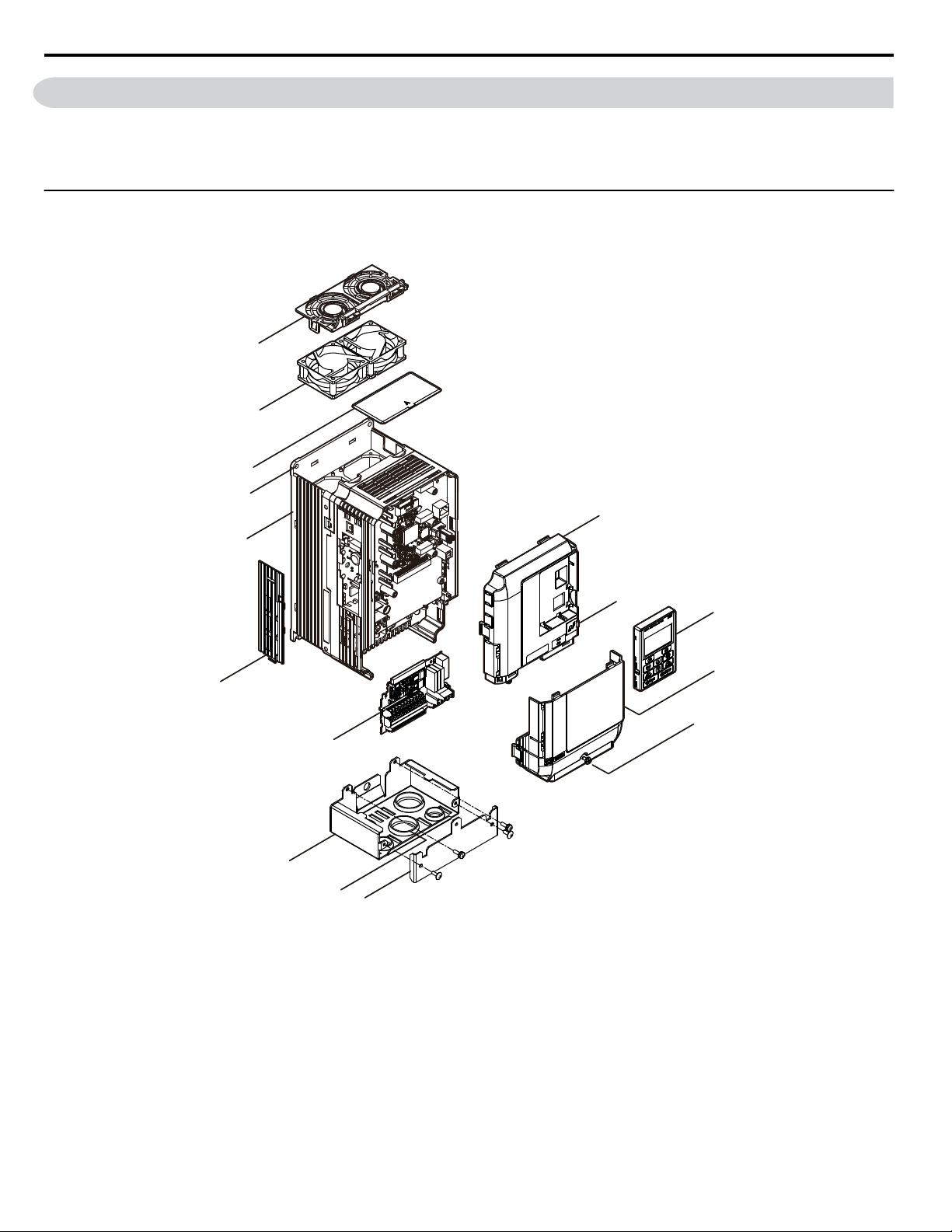
A
C
D
B
G
F
E
H
I
J
K
L
M
N
O
1.5 Component Names
1.5 Component Names
This section gives an overview of the drive components described in this manual.
Note: 1. Refer to Using the HOA Keypad on page 101 for a description of the operator keypad.
2. The drive may have no cooling fans or up to two cooling fans depending on the model.
u
IP20/NEMA Type 1 Enclosure
Three-Phase AC 600 V Class Models 5A0003F to 5A0032F
n
A – Front cover
B – USB port (type-B)
C – HOA keypad
D – Terminal cover
<1> Drive models 5A0006F and 5A0009F have a single cooling fan. Drive models 5A0003F and 5A0004F do not have a cooling
fan or a fan finger guard.
E – Terminal cover screw
F – Conduit bracket front cover
G – Rubber bushing
H – Conduit bracket
Figure 1.2 Exploded View of IP20/NEMA Type 1 Components
I – Terminal board
J – Optional 24 V DC power supply
connector cover
K – Heatsink
L – Mounting hole
M – Top protective cover
N –
Cooling fan
O –
Fan finger guard
<1>
<1>
28
YASKAWA ELECTRIC TOEP YAIZ1U 03A YASKAWA AC Drive – Z1000 User Manual

Three-Phase AC 600 V Class Models 5A0041F and 5A0052F
A
B
C
E
D
F
G
H
I
J
K
L
M
N
O
n
1.5 Component Names
A – Front cover
B – USB port (type-B)
C – HOA keypad
D – Front cover screw
E – Drive cover
F – Terminal cover
G – Conduit bracket front cover
H – Conduit bracket
Figure 1.3 Exploded View of IP20 Enclosure Components
I – Terminal board
J – Optional 24 V DC power supply
connector cover
K – Heatsink
L – Mounting hole
M – Top protective cover
N – Cooling fan
O – Fan finger guard
Receiving
1
YASKAWA ELECTRIC TOEP YAIZ1U 03A YASKAWA AC Drive – Z1000 User Manual
29

A
J
B
C
D
E
F
G
H
I
K
L
M
N
O
P
1.5 Component Names
Three-Phase AC 600 V Class Models 5A0062F to 5A0099F
n
A – Fan guard
B – Cooling fan
C – Fan bracket
D – Front cover
E – USB port (type-B)
F – HOA keypad
G – Drive cover
H – Terminal cover
Figure 1.4 Exploded View of IP20/NEMA Type 1 Enclosure Components
I – Conduit bracket front cover
J – Front cover
K – Conduit bracket
L – Terminal board
M – Optional 24 V DC power supply
connector cover
N – Heatsink
O – Mounting hole
P – Top protective cover
30
YASKAWA ELECTRIC TOEP YAIZ1U 03A YASKAWA AC Drive – Z1000 User Manual
 Loading...