

Page 1

YTerm Software Manual
Figure 1: YTerm Software Manual
Page 2

Page 3

YTerm Software Manual
WARNING
YASKAWA manufactures component parts that can be used in a wide variety of industrial
applications. The selection and application of YASKAWA products remain the responsibility
of the equipment designer or end user. YASKAWA accepts no responsibility for the way its
products may be incorporated into the final system design.
Under no circumstances should any YASKAWA product be incorporated into any product or
design as the exclusive or sole safety control. Without exception, all controls should be
designed to detect faults dynamically under all circumstances. All products designed to
incorporate a component part manufactured by YASKAW A must be supplied to t he end user
with appropriate warnings and instructions as to that part’s safe use and operation. Any
warnings provided by Yaskawa must be promptly provided to the end user.
YASKAWA offers an express warranty only as to the quality of its products in conforming to
standards and specifications published in YASKAWA’S manual. NO OTHER WARRANTY,
EXPRESS OR IMPLIED, IS OFFERED. YASKAWA assumes no liability for any personal
injury, prop erty damage, losses or claims arising from misapplication of its products.
Page 4

Page 5

YTerm Software Manual
Contents
Overview ........................................................................ 1
What's New for Version 7 ............................................. 1
SMC4000 support ..................................................... 1
Syntax Checker ........................................................ 1
Variable Tool Tip ....................................................... 1
Windows Skins (Look & Feel) ................................... 1
Performance ............................................................. 2
Introduction to YTerm ............................................... 2
Features of YTerm .................................................... 2
Getting Started .............................................................. 4
Installing YTerm ........................................................ 4
Software Kit Contents .......................................... 4
System Requirements ......................................... 4
Software Installation ............................................ 4
Launching YTerm ..................................................... 7
Using YTerm ........................................................... 12
The Programming Screen ................................. 12
Navigating Around the Programming Screen .... 12
The Edit Windows .............................................. 13
The Help Window .............................................. 15
The Program Errors and Program Warnings
Windows ............................................................ 16
The Terminal Window ........................................ 17
The Event Logger .............................................. 19
Ethernet Status .................................................. 20
Program Monitoring ........................................... 21
The Next Button ................................................. 22
The Tuning Screen ............................................ 23
Manual Tuning ................................................... 24
Autotuning ......................................................... 25
Testing the Tuning ............................................. 27
Viewing the Tune Test Results .......................... 28
Printing The Graphs .......................................... 29
Page 6

YTerm Software Manual
Storage Scope ...................................................30
Viewing the Scope Results ................................32
Saving the Gains on the SMC Controller ...........32
SMC Parameter Utility .......................................33
Sigma Servo Amplifier Setup .............................34
Emergency Stop Button .....................................36
The Monitoring Screen .......................................36
Axis Output ........................................................37
Local I/O .............................................................40
Dedicated I/O .....................................................41
Appendix ......................................................................42
SMC to RS-232 Connection (SMCCBL7 cable) ......42
Sigma Servo Amplifier to PC Connection
(YS-11 cable) ..........................................................43
Theory of Operation of the Autotuning Algorithm ....44
Index .............................................................................45
Page 7

YTerm Software Manual
Overview
What's New for Version 7
SMC4000 support
The latest version was modified and tested to work with the recently released
SMC-4000 controller.
Syntax Checker
Programs are automatically syntax checked before being transferred to the
controller. This will save the programmer considerable time by helping to
identify errors that would prevent the program from running. Warnings and
recommendations are also given when the program is analyzed. In addition,
the syntax check is performed based on the selected controller, allowing it to
identify and check for compatibility or command differences from controller
to controller.
Variable Tool Tip
When the mouse is held over a highlighted user or internal variable in the
program window, the tool tip reports the current value in the controller. This
is very helpful for debugging. The variable can be an entire math
expression, and it doesn't even need to be in the program currently executing
in the controller. This allows programmers to test a calculation of formula
live. Any phrase that can be typed into the terminal window by preceding it
with the MG command can be updated with a tool tip in the programming
window.
Windows Skins (Look & Feel)
A new look has been given to YTerm; the user can select the appearance of
the windows and controls on each of the windows. The toolbar has been
changed from a vertical toolbar to a more standard, horizontal style. Finally,
a standard menu system has been incorporated.
Other visual changes include the addition of a tab system for the Terminal
Window, Help, and Syntax Checker.
1
Page 8

YTerm Software Manual
Performance
Communications have been improved to process data at much higher rates.
This allows faster upload and download of programs and faster viewing of
graphical data such as during tuning and scope.
Finally , the speed of program formatting to show comments in green has
been dramatically increased, and a utility has been added to format the
program into an easier to read layout, especially when it has been uploaded
from a controller.
Introduction to YTerm
YT erm is a front-end software package for the Yaskawa SMC Series Motion
Controller. YTerm provides a user-friendly Windows interface for design,
development and debugging of motion control applications. The software
package consists of three main sections:
• Programming Section - edit, transfer, and monitor programs for the
motion controller.
• Tuning Section - tune the SMC's axis and test the servo system's
performance using a four-channel scope to graph performance data.
• Monitoring section - monitor motion and I/O on the controller.
Features of YTerm
YTerm enables full control and programming of the SMC using:
• Text editor with dual edit windows for user programs and ar ray data.
• Find/replace support.
• Multiple step Undo function.
• Selectable program compression and error checking during upload.
• Real-time monitoring of program execution (includes multi-tasking).
• Full screen zoom capability in programming, online manual, and
terminal window section.
• Extensive on-screen context sensitive SMC keyword help text.
• Graphical online manual and auto tuning.
• Online scoping of up to four channels of data.
• Quick load/save of SMC parameters in and out of the controller.
• Real-time monitoring speed, position error, position, and torque for all
connected motors (numerical and graphical).
• Real-time monitoring of all analog and digital I/O.
• Sigma servo amplifier quick setup (Hardware required: YS-11 cable).
• Context sensitive pop-up menus and standard menus.
• Online ASCII Terminal emulator window.
2
Page 9

YTerm Software Manual
• Scroll-back buffer for viewing data in the Terminal window.
• Clipboard access to the Ter minal window.
• Full text logging of all events in the Terminal window.
• Context sensitive help in all screens, accessible through F1 key.
• Event logging of program status.
• Ethernet communications and support.
• Firmware upgrading.
• Live evaluation of variables and expressions.
• Clipboard access to the Ter minal window.
• Scroll-back buffer for viewing data in the Terminal window.
• Full text logging of all events in the Terminal window.
• Find/replace support.
• Multiple step Undo & Redo functions.
• Context sensitive pop-up menus.
Page 10

YTerm Software Manual
Getting Started
Installing YTerm
Software Kit Contents
The YTerm software kit (SMCGUI1) should include the following:
• One CD ROM labeled 'YTerm SMC Development Environment.'
• The YT erm Software Manual, YEA-SIA- SMC-1.1.
• One programming serial cable, SMCCBL7.
• A Software Registration card.
If any of the YTerm items are missing or damaged, contact Customer
Service at Yaskawa Electric America for replacement, telephone number 1800-YASKAWA.
System Requirements
YTerm requires the following minimum PC system configuration:
• A Pentium 233 MHz, 32MB RAM.
• VGA resolution monitor.
• An asynchronous adapter (RS-232 Serial port) on the computer.
• Microsoft Windows 95, 98, NT, 2000, or XP.
Software Installation
Exit other programs as a precaution against a program conflict occurring the
first time the software is installed.
All the files required for setup are contained on the CD ROM. Before using
YT erm, run the YTerm YTERM.EXE program. This program decompresses
and copies the YTerm program and its associated files onto your PC hard
disk.
YTERM.EXE does not modify CONFIG.SYS, AUTOEXEC.BAT, WIN.INI
or SYSTEM.INI. It may update Windows components.
4
Page 11
YTerm Software Manual
To run the INSTALL program:
1. Start Microsoft Windows.
2. Insert CD ROM into CD ROM drive.
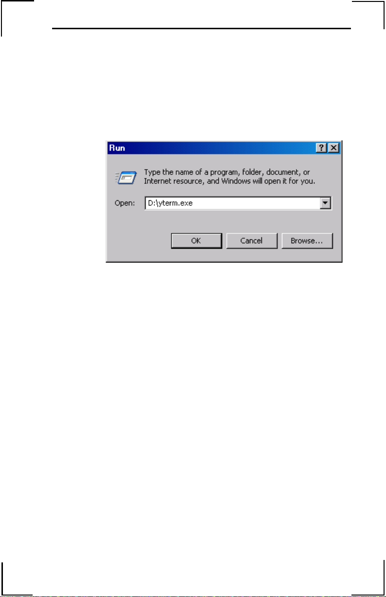
3. Select the Run option from the Start Menu in Windows 95, 98, NT, 2000 and XP.
4. Type D:\yterm.exe (Your system may use a different letter designation for the CD ROM drive).
Figure 1: Run Dialog Screen
5. Press OK. Click the YTerm Software butt on under the Install Software heading.
6. Read the instruction screen and press Next to proceed.
7. Enter the user name and company name information and press Next.
8. Select in the desired folder for copying the YTerm files. Press Next to proceed.
9. The “Ready to install the application” window appears. Press Next to proceed.
10. The INST ALL program will now copy files from the CD ROM to the selected folder.
Note: At this time, please complete your Yaskawa software registration
card found in the YTerm Software kit. This is necessary in order to
provide updates and support to registered users.
11. The installation is now complete. Press Finish to end the installation program.
Page 12
YTerm Software Manual
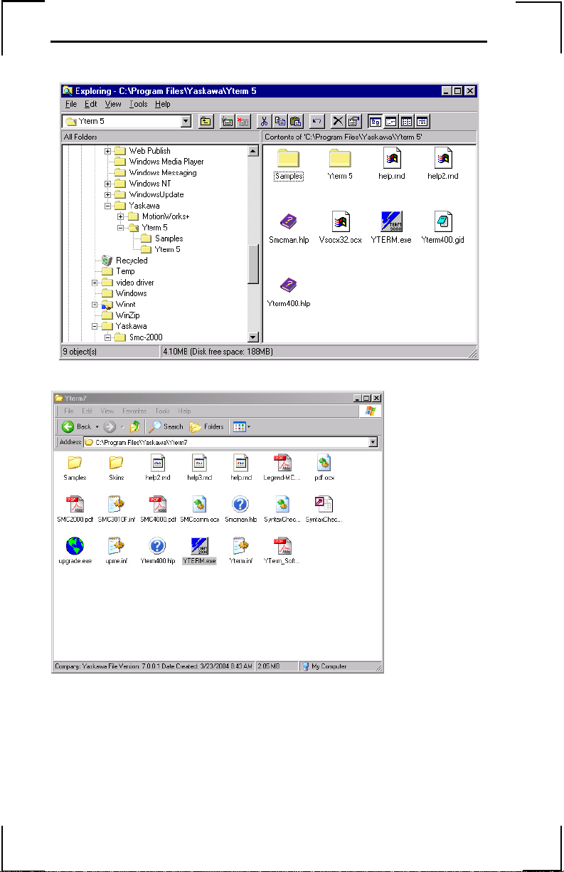
Upon completion of a successful installation, the YTerm icon will appear on
the PC desktop window:
Figure 2: YTer m Program Group in Windows 95
Figure 3: YTerm Program Group in Windows XP
YT erm creates a W indows program group that defaults to Yaskawa Software
and creates four program items ("shortcuts"):
1. YTerm (The SMC communication program)
6
Page 13

YTerm Software Manual
Launching YTerm
To run YTerm, double click on the YTerm icon.
The following screen (Figure 4) will appear, while the application loads
indicating the version number and release date, and any user information
entered during the installation process.
Figure 4: YTerm Startup Splash Screen
This screen will display for a few seconds while the application loads. When
the application is loaded, it will attempt to establish communication with an
SMC. The connection will be based on previously saved communication
parameters. The first time the program runs, it will use the first free
communication port in the computer, and the connection will default to
19200 baud.
7
Page 14
YTerm Software Manual
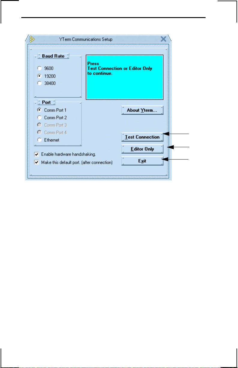
If the communication access attempt was successful, the following screen
appears:
(A)
(B)
(C)
Figure 5: Communication Setup Screen Showing Successful Communication
To enable hardware handshaking, select the Enable Hardware
Handshaking check box. Press Continue to proceed to the first
(Programming) screen.
Note: Hardware handshaking is the recommended mode of operation.
The default setting is enabled.
To view the “About YTerm” screen, double click on the About YTerm
button. Press Exit to exit YTerm.
8
Page 15

YTerm Software Manual
If the communication access attempt failed, this screen will display the "No
Connection" message as follows:
(A)
(C)
(D)
Figure 6: Communication Setup Showing Unsuccessful Communication Attempt.
Figure 7: Communication Setup Showing Ethernet Setup
9
Page 16

YTerm Software Manual
Baud Rate: Select the baud rate that has been set by either DIP switches or
jumpers on the SMC, depending on the controller. For all
controllers, the default baud rate is 19200.
Port: Select the port which corresponds to the location on the computer
where the serial cable has been connected. If a LEGEND–MC or
SMC–4000 controller is used, Ethernet is a communication option.
If Ethernet is selected, the controller’s IP address must be entered.
The window will change display to allow entry of this information
as shown in Figure 7. Note: The local IP address setting is shown
on the screen. If the number is all zeros or something like 127.0.0.1,
this means that the PC’s Ethernet settings are not properly set (in
Network, TCP/IP settings). Also note that if the cable is properly
connected, both the PC’s Ethernet status LED and the one on the
controller will show a valid connection (Typically via a green LED
next to the Ethernet Port). The LEDs should be ON even before the
actual software connection is established.
About YTerm: Click to view the “About YTerm” window, including
version information. System information can be gathered from this
window by pressing the system information button. This
information may be helpful to Yaskawa software development
should incompatibility issue arise.
Enable Hardware Handshaking: To enable hardware handshaking, check
the check box. This is the recommended method for serial
communication. The default setting is “enabled”.
Default Port: The check box that refers to the default port will send the CF
command to the controller after connection. This will cause the
controller to redirect unsolicited information to the port that YTerm
has just opened. This will allow messages from the controller to be
viewed in the terminal window.
Force Connection to Last Handle: If checked, YTerm queries the
controller using _IA3 to determine what handle it is on. If it is not
on the “P” for LEGEND-MC or “H” for SMC4000, then YTerm
sends the HS command to switch handles making the YTerm
connection on either “P” or “H.” This keeps YTerm out of the way
of other devices that the controller might make a connection to
later.
Test Connection: Initiates communication with the controller. Once
communication has been verified, the status panel at the upper right
of the form will turn green, and the controller’s serial number, axis
count, and the firmware version are displayed. Press Continue after
the connection window appears. If connection was not verified, the
status panel will turn yellow.
10
Page 17

YTerm Software Manual
Editor Only: If YT erm is to be used for viewing or editing programs while a
controller is not present, select Editor Only. This will allow YTerm
to operate without using a communications driver. Only the
programming window will be accessible in the Editor Only mode.
Note: If the controller is in “monitor mode”, a mode where the firmwar e
is not executing, YTerm will detect this and assume that a firmware
upgrade attempt has previously failed. If this is the case, YTerm will
attempt to download firmware to the controller again if requested. This
feature is only applicable if connected to an SMC–3010 or SMC4000
controller.
When establishing communications with an SMC, check all cable and power
connections. Make sure that the cable between the computer and motion
controller is plugged into the correct computer port. Verify the computer port
matches the one selected in YTerm.
Press Test (A) to try to establish communication once more and press
Continue (B) upon seeing the connection screen.
If problems persist, contact technical support.
Press Editor Only (C) to work in offline mode if there is no SMC
connected. In offline mode, only the Programming screen is available.
Press Exit (D) to exit YTerm.
Note: All SMC units are configured for 19200 baud rate by default.
11
Page 18

YTerm Software Manual
Using YTerm
The Programming Screen
Figure 8: Programming Screen.
After YTerm is running and communication with the SMC has been
established, the Programming Screen (Figure 8) is displayed. Use this screen
to develop and execute SMC programs.
Navigating Around the Programming Screen
The menus in the menu bar have most of the options from the Edit Toolbar
and the pop-up menus found throughout YTerm and are explained where the
pop-up menu is explained. The other options are explained here.
• The File menu shows the last 7 programs that were accessed by YTerm
to allow quick access to the programs.
• The Format menu contains skin options.
• The Program menu contains the Syntax Check and automatic forma tting
of the program.
Click on a specific icon on the screen to activate. For example, to select one
of the editing windows, move the mouse pointer to the desired working
window and click the left mouse button. The title of the active window is
highlighted while the title of the other editing window will be gray.
12
Page 19

YTerm Software Manual
T o edit one of the programs in full screen view, click the full screen button in
the upper-right corner of the program window. Click the button again to
return to normal viewing.
Key Commands (shortcuts) are available:
• Alt+1 moves the cursor to the editing window on the left.
• Alt+2 moves the cursor to the editing window on the right.
• Alt+3 moves the cursor to the Help pull down menu if the Help tab is
active.
• Alt+4 moves the cursor to the terminal window if the Terminal tab is
active.
The Edit Windows
YTerm provides the ability to add comments to the program. Any program
line beginning with a double slash (//) will be ignored as the program is sent
to the SMC. Comments can also be placed after a valid command or
commands, and once the (//) is found, the remainder of the line will not be
uploaded. This makes it possible to add as many comments as needed
without overloading the controller's memory with comments.
While holding the Control (Ctrl) key down and highlighting a user or
internal variable in the program window with the mouse, the tool tip reports
the current value in the controller. The variable can be an entire math
expression, and does not need to be in the program currently executing in the
controller. This allows a live calculation of a formula. Any phrase that can
be typed into the terminal window by preceding it with the MG command
can be updated with a tool tip in the programming window.
The Toolbar and the Pop-up menu provide program editing functions.
Figure 9: The Edit Toolbar.
Note: The functions accessed through the Toolbar are for the active edit
window.
13
Page 20

YTerm Software Manual
Most of the tools look like and have the same function as the tools in other
Windows programs. The ones that do not are explained as follows:
• Find/Replace: Displays a dialog box for finding and replacing text in a
program.
• Goto: Displays a dialog box for jumping to a given line number in a
program.
• Switch Window: Exchanges the visible program for the one that is not
visible (if the program window is maximized).Get From Controller:
Downloads a program or array that is stored in the controller.
• Send To Controller: Uploads a program or array to the controller.
• Execute: (Green light) Sends the EXECUTE (“XQ”) command to the
controller.
• Stop: (Red light) Sends the STOP (“ST”) command to the controller.
The Pop-up Menu is accessed by clicking the mouse's right button while the
cursor is located in one of the edit windows. The Active window is
highlighted. The pop-up menu is shown below:
Figure 10: The Edit Pop-up Menu
The pop-up menu has the following options:
• Select Cut to transfer the current selection onto the clipboard.
• Select Copy to duplicate the current selection onto the clipboard.
• Select Paste to insert the contents of the clipboard onto the page at the
current cursor position.
• Select Undo to cancel the last (or more) edit.
• Select Goto to move to a specific line in your program.
14
Page 21

YTerm Software Manual
(B)
• Select Print to print out the program or selected text (in the active
window) on the default printer. To change the default printer, refer to
your operating system manual.
•Mark Send Compressed to remove all "//" comments, spaces and to
delete empty lines before sending the program to the controller. Select
this again to send the program to the "as is" except for changing all "//"
comments to native SMC comments ("NO").
Note: Send Compressed is the default setting. A compressed program
will execute slightly faster.
• Select Array Mode to use the edit window to send, receive, load and
save array data. Comments are not allowed in arrays. When the Array
Mode is selected, Send Compressed is disabled. All arrays are
compressed before being sent to the controller.
• Select Find/Replace to search the program in the active window for
text. If text is highlighted before selecting this function, the selected text
will be used as the text to seek. This can also be used to replace text in
the program.
The Help Window
(A)
Figure 11: SMC HelpWindow.
The Help window provides descriptions for the SMC programming
language. Get descriptions on any command by the use of two methods:
1. When one of the two programming windows is selected, the
Help window will update to show descriptions for the command on the current line.
2. A description for any command can be viewed by entering the
two letter command in the Keywords box (Figure 11). By
clicking on the down arrow (located next to the box) a list of
available commands will appear. Select the desired command.
Scroll up and down the list with the vertical scroll bar (located
next to the list) to view keywords.
15
Page 22

YTerm Software Manual
If detailed descriptions on SMC commands is needed, press the Manual (A)
button. The SMC Online Manual (if installed) will come up in a separate
window.
To copy text from the Help window, select the text to be copied by pressing
on the mouse button while dragging the cursor over the text. Release the
mouse button and click on Copy (B) to duplicate the selected text onto the
clipboard.
Double clicking on the Help window or clicking the button in the upper-right
corner of the window will display the window in full screen view. Double
clicking or hitting the button again will return the window to normal view.
The Program Errors and Program Warnings Windows
The Program Errors and Program Warnings windows display diagnostics
after Syntax Check from the Program menu has been selected, after sending
the program to the controller has been attempted, or after loading a program
from a file. Programs are automatically syntax checked before being sent to
the controller. The syntax check is performed based on the selected
controller, allowing it to identify and check for compatibility or command
differences between different controllers.
The Program Errors Window displays problematic code, the line number
that the problem appears, and a diagnosis. These problems must be fixed
before the program can be sent to the controller.
The Program Warnings Window displays suggestions to the code. These
suggestions do not need to be fulfilled for the program to be sent to the
controller, but are recommended.
16
Page 23

YTerm Software Manual
The Terminal Window
The Terminal window functions as a terminal emulator connected to the
SMC. Commands typed here are executed by the motion controller after the
(Enter) or (;) (semi colon) key is pressed. Pressing the F3 key will auto
repeat the last command.
The Terminal window can also be used (by the SMC) to display controller
status information such as I/O, debug messages, input prompts, error
messages, etc.
The Paste button completes the transfer of the text (from the clipboard) onto
the Terminal window.
The T erminal window has a pop-up menu similar to the Editing window that
is accessed by clicking the right mouse button while the cursor is on the
Terminal window. The pop-up menu provides functions to communicate
with the controller such as enabling or disabling servo power, status
reporting, and logging features.
When the terminal window pop-up menu is active, the following menu will
appear:
Figure 12: The Communication Pop-up Menu.
17
Page 24

YTerm Software Manual
The pop-up menu has the following options:
• Execute: Starts the current program in the controller.
• Stop: Sends an “ST” command to stop any running motors. This
command also stops the applicaiton program from running.
• Logging: Provides access to the sub-menu for capturing data to a file
(SMCLOG.LOG) of communication in the terminal window.
• Start Logging: Start s writing all communication to the SMCL OG.LOG
file. Once the log file is started it will continue to log the events in the
Terminal window. The file size will continue to increase until logging is
stopped or YTerm ends.
• Stop Logging: Stops writing to the SMCLOG.LOG file.
• View Log File: Loads the SMCLOG.LOG file in Microsoft Write for
viewing.
• Abort: Stops the execution of the current program in the controller.
• Enable all Servos: Energizes (enable) all servos.
• Disable all Servos: De-energizes (disable) all servos.
• Ethernet Status: Displays a form which contains details about the
Ethernet communications. See Ethernet Status.
• Tell Error: Displays the current position error of all servo motors.
• Tell Position: Displays the current position of all the connected servo
motors.
• Program Status: Allows the observation of the pr ogram execution. See
Program Monitoring.
• Reset Communication: Resets the communication channel between
the PC and the SMC. This clears any existing communications by
closing the serial port, restarting it again, and verifying that YTerm can
communicate with the SMC. It also redetermines the number of axes on
the LEGEND–MC controller. If Ethern et communication is selected,
connection to the host is reattempted.
• Firmware Upgrade: Upgrades the firmware on a LEGEND–MC or
SMC–4000 controller via the serial port only. Only the LEGEND-MC
and SMC-4000 controllers can have firmware upgraded through YT erm,
and upgrading must be done through the serial port. Once initiated, the
process must not be interrupted, or the controller may fail to restart.
Select the firmware file (*.HEX) from the browser window that will
appear, and the firmware will be automa tically downloaded to the
controller. (The SMC-2000 cannot be upgraded with YTerm; it requires
a chip change.)
• Terminal Font Settings: Selects custom fonts for text in the Terminal
window. The settings will be retained for future sessions.
• Copy all Terminal to Clipboard: Copies the contents of the entire
Terminal window buffer (up to 50K) to the clipboard.
• Print Terminal Buffer: Prints the entire content of the Terminal
window buffer or selected text.
18
Page 25

YTerm Software Manual
The Event Logger
Double clicking on the status bar at the bottom of the YTerm screen shows
the Event Logger. The Event Logger timestamps each event that YTerm has
executed along with the status of the events and lists them in a window.
Figure 13: The Event Logger
Notes: If the log file is started and not stopped, it will continue to log the
events in the Terminal window.
The file size will continue to increase until the device is tured OFF or
upon exiting YTerm.
19
Page 26

YTerm Software Manual
Ethernet Status
The Ethernet Status window will show the connection status of each handle
on the controller. Details include TCP/UDP, master or slave, and IP address
of the connected devices. The Ethernet Status window is updated in realtime.
Figure 14: Ethernet Status Window
20
Page 27

YTerm Software Manual
Program Monitoring
Once a program has been created and sent to the controller, it can be
monitored with this function. The Program Status window, shown in Figure
15, is accessed through the pop-up menu on the Terminal window or through
the Tools menu in the menu bar.
Figure 15: The Program Status Screen.
The current status of each of the four programs is displayed at the top of the
window. This includes the state of the program (Running, At Trippoint and
Not Running) and the current line being executed. It is possible to execute
the controller's program from the Terminal window or the Pop-up menu of
the Terminal window, and then view the Program Status.
The middle portion of the window will indicate the state of the axes. Select
the axes to monitor using the check boxes.
A status bar at the bottom of the window indicates the SMC status.
Programs are executed by clicking on the left mouse button. When a
program is executing, the button text will say “Stop Program”, and when the
program is halted it will indicate “Execute Program.”
Select Cancel to stop monitoring and return to the Programming screen.
21
Page 28

YTerm Software Manual
In the event of a program error, YTerm will display the reported error and the
line on which it occurred. This will replace the top portion of the window
(which displays the program status) with the Error Report as shown below in
Figure 16. Important Note: The line number indicated may not coincide with
the line number as viewed in the Programming window. This is due to the
program compression that takes place. Use the LS command in the Terminal
window to view the line number specified. Example: Line 8 indicates an
error, so use the command LS 1,15 in the Terminal window.
Restart the programs by selecting Execute Program.
Figure 16: Error reporting in the Program Monitoring Screen.
The Next Button
To switch to the Tuning Screen, click the Next button. The Next button is
also used to advance to the next screen elsewhere in YTerm. The Next
button icon will appear on each screen located in the lower right corner .
Figure 17: The "Next" Button
22
Page 29

YTerm Software Manual
The Tuning Screen
Figure 18: Tuning Screen
Figure 18A: Tuning Screen (Linear Servo Motor)
23
Page 30

YTerm Software Manual
The Tuning screens (Figures 14 and 14A), are used to set the gains of the
servo motors. See the SMC User's Manual for a detailed explanation about
tuning a servo system.
The Terminal screen is not resizable when shown on th etuning screen.
Note: Use the Axis Selection Panel to select the motor to tune. Only one
motor can be tuned at a time.
Manual Tuning
See the SMC User's Manual for proper tuning technique.
In order to manually tune a servo system connected to the SMC Controller:
1. Select the axis by clicking on the appropriate radio button on the axis selection panel.
2. Use the terminal window to send the SH* (where * = X, Y, Z, W, E, F, G, H) command to enable the servo motor.
3. Set default values for the gains.
4. Increase KP, KD, KI gains accordingly, by moving the
horizontal scroll bars above each gain label. Moving the bar to
the right increases the value of the gain, moving it to the left
decreases it. It is also possible to type the commands directly
into the terminal. THe scroll bar will update when a radio
button is pushed.
5. For KI and KP, click inside the bar to change the value by 1. Click the arrow on the bar to change the value by 0.1.
6. For KD, click inside the bar to change value by 10. Click the arrow on the bar to change value by 1.
24
Page 31

YTerm Software Manual
Autotuning
• YTer m includes a routine that autotunes a connected servo system. This
function is able to tune most systems. Systems can be tuned with five
levels of rigidity.
• See the Appendix for details on the theory of Autotuning.
In order to Autotune a servo system:
1. Select the axis to be tuned, by clicking on the appropriate icon button in the axis selection panel.
2. Use the terminal window to send the SH* (where * = X, Y, Z, W, E, F, G, H) command to enable the servo motor.
3. Click on the Autotune button. The dialog screens shown in Figures 15 and 15A will appear. If Autotuning was previously performed on this axis, previous values used will be loaded.
Figure 19: Autotuning Dialog Screen
25
Page 32

YTerm Software Manual
Figure 19A: Autotuning Dialog Screen
4. Select the desired level of rigidity for tuning the system from the Rigidity Setting panel.
5. Select the desired machine configuration (appearing in the Advanced Configuration panel) from the available options list.
6. Enter the motor to load gear ratio.
7. Check the Use Integrator (KI) box to include the integration constant of the PID loop in the autotune calculations.
8. Select the correct number of Pulse per revolution prequadrature for your specific motor or the linear scale resolution
if a linear encoder is to be turned.
9. Click on Tune to execute the Autotune program. Click Cancel to close the dialog screen and cancel the Autotune operation.
Note: Autotuning does not display a graph.
26
Page 33

YTerm Software Manual
Testing the Tuning
Once a servo system is tuned, use the “test” tuning function and observe the
performance of the system. The test will execute a small program in the
controller based on a user-defined motion profile.
In order to run the test program:
1. Select the axis (to which it is connected) by clicking on the appropriate icon button in the axis selection panel.
2. Use the terminal window to send the SH* (where * = X, Y, Z, W, E, F, G, H) command to enable the servo motors
3. Click on Test. One of the dialog box es shown below will appear.
Figure 20: Tune Test Dialog Screen - Servo
27
Page 34

YTerm Software Manual
Figure 20A: Tune Test Dialog Screen - Linear
4. Define the motion profile by entering the motion parameter fields in the screen's appropriate boxes. Be sure to select the direction of motion and the correct Encoder pulses per rev.
5. Click on Execute to execute the test program.
Viewing the Tune Test Results
After the controller completes sampling the data, the information is
transferred to the PC and displayed as follows:
Figure 21: Tune Test Results Window
28
Page 35

YTerm Software Manual
Double clicking in the graph window will display the window in full screen
view. Clicking Cancel will return the window to normal view.
In full screen view, zooming in is available by click-and-dragging the mouse
to form a box around the area to zoom into. The coordinates of the cursor
are displayed in the first button. The other buttons run functions and are
explained below. Some of these functions are available in normal view by
right-clicking the graph.
• Restore Graph: Returns the graph scale back to the default scale.
• Adjust Axis: Changes the scale of the axes so that the X and Y scale are the
same (if zoomed in). This is only useful when plotting Channel 1 vs. Channel
2 with the Scope.
• Export Data: Outputs graph data points to a text file. The columns are separated by tabs if there is more than one channel being recorded.
• Print Graphs: See Printing The Graphs.
• Copy: Puts the graph image into the Windows Clipboard.
• Cancel: Changes view back to normal.
Printing The Graphs
The graphs of the tuning test or scope with all of the parameters can be
printed by clicking on the Print button. Yterm will print out the three graphs
(Tuning Test) or one graph (Scope) on the default printer. Use Window’s
Printer Manager Program to change the default printer.
29
Page 36

YTerm Software Manual
Storage Scope
The storage scope is used to store data. This allows the user to choose the
parameters observed and duration. Th e storage scope has the capability to
store up to four parameters (dependent on the type of graph selected).
To run the Storage Scope:
1. Click on Scope on the Tuning Screen to display the screen
shown below:
Figure 22: Storage Scope Parameters Screen
2. Determine and select Sample Time (in milliseconds) so the Controller will sample the selected data at the appropriate intervals.
3. Determine number of points to sample and display on the graph.
4. The time frame in which the controller samples the data is a function of: Sample Time x Points to Graph. This number is displayed in Scope Time frame box on the Storage Scope Graph.
5. Enter an optional command to be executed before starting to store the data. Example: Enter the command XQ to execute the program on the controller.
30
Page 37

YTerm Software Manual
6. Choose the type of graph. Three graph types are available:
• Time Graph - displays up to four (4) channels of data as a
function of time.
• Two Dimensional Data Graph - displays a plotted line as a
function of two (2) channels of data.
• Three Dimensional Data Graph - displays a plotted line as a
function of three (3) channels of data.
7. Define the data to be sampled. Click on the desired channel tab. The dialog box appears as follows:
Figure 23: Storage Scope Parameters Channel Screen
8. Select Axis (or I/O) to sample. Select none if nothing is to be stored on this channel).
9. Select the Data to be stored.
10. Select the Color of the line to be plotted.
11. Select the Thickness of the line to be plotted.
Note: Two Dimensional and Three Dimensional graphs' line color and
thickness is determined by the line color and thickness selected in
Channel #1.
12. Enter Engineering Units value.
Note: One (1) is the minimum engineering unit conversion. Use the
engineering units field to convert stored data from encoder counts to the
desired unit.
31
Page 38

YTerm Software Manual
13. Repeat Steps 7 through 11 for other data parameters to be stored.
14.Click Start to begin storing data.
Viewing the Scope Results
After the controller completes sampling the data, the information is
transferred to the computer and displayed as follows:
Figure 24: Example of Storage Scope Graph Screen
Saving the Gains on the SMC Controller
To write the gains to the motion controller, click on Burn Gains button.
After verifying this, the gains are burned onto the SMC's EPROM (This is
the equivalent to typing BN in the Terminal window). The gains will now be
saved even when the power is disconnected.
Notes: If the gains are not burned, they will be lost after a software or
hardware reset of the SMC.
Several parameters not shown on the tuning screen are also saved when
burn is executed. Check the BN command page in the SMC manual for
a complete list
32
Page 39

YTerm Software Manual
SMC Parameter Utility
Figure 25: Parameter Setup Screen
The SMC Parameter Setup screen makes it possible to upload, download,
save-to- file, and load-from-file parameter sets for the SMC.
Parameters are grouped according to function. By clicking on the desired
function's tab, the current parameters of that group are displayed:
• Select Receive to download the SMC parameters into YTerm.
• Select Open to open a parameter set from a file.
• Select Send to send the current parameters set to the SMC.
• Select Save to save the current parameter set into a file.
• Select Print to print the current parameter set on the default printer. To
change the printer, use W indow's Printer Manager Program to change the
default printer.
Note: Open will open the parameters into YTerm, but will not send
them to the SMC.
33
Page 40

YTerm Software Manual
Sigma Servo Amplifier Setup
The Sigma servo amplifier setup program is designed for configuring the
amplifier to work with the SDGA and SDGB only.
Disconnect the serial communications cable from the SMC and connect the
Yaskawa YS-11 Serial Communication Cable to the servopack.
Once this is done, run the setup program from YTerm using the Servopack
button.
Connection will be established with the Servo amplifier, the result is a return
of the servo amplifier's present settings, and should look similar to Figure
26.
Figure 26: SMC/SIGMA Setup
1. Click on Cancel to cancel the current servo amplifier setup.
2. Click on Change present settings to required button to change
the servo amplifier settings to match the required ones After this
is done, a dialog will appear asking wether an absolute encoder is
to be installed. If yes, it will request the selection of the desired
pulse gain dividing ratio.
34
Page 41

YTerm Software Manual
Now your servo amplifier is configured for work with the SMC. The result
should now look like Figure 27.
Figure 27: SMC/SIGMA Setup screen (after setup is complete).
Click on Exit to return to YTerm. Disconnect the Yaskawa YS-11 Serial
communications cable. Reconnect the standard serial communications cable.
Resume connection to the SMC via YTerm.
35
Page 42

YTerm Software Manual
Emergency Stop Button
In the event that it becomes necessary to stop the motion of the attached
servo system, click on the Stop button. This will issue Abort (AB) and
Motor Off (MO) commands to the SMC for the selected axis. While
executing Autotune and Tune Test, the stop button will stop the selected
axis, and cancel the function, otherwise all axes will be stopped.
Note: The Abort command will stop all program execution. The Motor
Off command will turn off the command functions to the selected motor.
The Monitoring Screen
Figure 28: The Monitoring Section Screen.
The Monitoring Section screen, shown in Figure 28, provides the ability to
observe the status of selected axes. This screen can be used to track motion
parameters, inputs, and outputs.
Choose specific axes to be monitored, and select which parameters are to be
returned. There are tabs to select from three screens of SMC status
information.
1. Axis Output - Position, Position Error, Speed and Torque.
2. General IO - Digital Inputs, Digital Outputs and Analog Inputs.
3. Dedicated IO - Forward, Backward Limit and Home switches.
36
Page 43

YTerm Software Manual
Axis Output
Selecting the Axis Output tab will display a screen to enable monitoring of
any servo system on the SMC's axes. The monitoring consists of returning
in real-time, the values of any of the following parameters:
• Position
• Position Error
•Speed
• Torque/Force
Select any combination of the available axes to monitor. This is done by
clicking on the button with the letter representing the desired axis in the data
monitoring panel. The buttons are labeled X, Y, Z, W, E, F, G, H.
T o stop monitoring an axis, press again on the Axis Selection button for that
axis. T o select a parameter for monitoring, click the check box located left of
the name label of the desired parameter.
The axis outputs can be displayed in listing or in graphical format as shown
in Figures 29-30.
To switch between the two modes of display screen, Press the Display List/
Display Graph button on the Axis Output Screen.
Figure 29: Axis Output Screen - List Display
37
Page 44

YTerm Software Manual
Figure 30: Axis Output Screen - Graphic Display
The Max. and Min. fields are used to enter the upper and lower range of
values to be displayed. The points field will determine how many points of
data are displayed on the graph.
38
Page 45

YTerm Software Manual
Note: Be certain that the Min. and Max. values include the actual range
of values that the controller is reporting. This can be verified through
the listing mode (see below).
Figure 31: Engineering Unit Setup Screen
The Engineering Unit Setup Screen enables the user to enter pre-determined
motions (engineering units) into the controller to be able to retrieve data in
the units of measure related to the particular application.
To enter the engineering units for a program:
1. Select the desired Axis.
2. Enter name in the parameter (position, pos. error, speed, torque).
3. Enter the engineering unit factor (counts, counts/s., volts).
4. Select Set Units.
Click on Reset axis to encoder counts to restore to default values and
continue monitoring with the default (1) engineering units.
39
Page 46

YTerm Software Manual
Local I/O
Figure 32: Local IO Monitoring Screen.
Selecting the Local IO tab will enable the monitoring of any I/O connected
to the SMC. The monitoring consists of returning in real-time, the values of
any of the following parameters:
• Digital Outputs
• Digital Inputs
• Analog Inputs
The digital inputs and outputs are banked. In groups of eight, click on the
check box located to the left of the bank to activate. The bank will update in
real time as the status on the SMC changes. Check boxes only appear for I/O
that exist on the connected SMC.
For digital outputs, green boxes indicate low (i.e. "ON"), dark gray indicate
high (i.e. "OFF"), and light gray indicates not available.
For digital inputs, yellow boxes indicate high (i.e. "ON"), dark gray
indicates low (i.e. "OFF"), and light gray are not available.
The analog inputs are activated in a similar way, each one with its own check
box. The analog value of the input is displayed next to its check box.
It is possible to "force" the status of a digital output by clicking the buttons.
After the output is clicked, the status will change from high to low, or low to
high, identified by a color change when YTerm reads the output status from
the controller.
40
Page 47

YTerm Software Manual
Dedicated I/O
Figure 33: Dedicated IO Monitoring Screen.
Selecting the Dedicated IO tab will enables the monitoring of the limits and
home inputs on the SMC. The monitoring consists of returning, the values of
any of the following parameters in real-time:
• Forward Hardware Limits
• Reverse Hardware Limits
• Home Switches
The dedicated I/O are banked in groups of eight. To make a bank active,
click on the check box next to the bank. Check boxes only appear for I/Os
that are connected on the SMC.
Green boxes indicate inputs that are active, regardless of their on-state
configuration, dark gray indicates the inputs are not active, and light gray
indicates not available.
41
Page 48

YTerm Software Manual
Appendix
SMC to RS-232 Connection (SMCCBL7 cable)
The layout of the connection cable between the SMC and the PC serial port
(RS-232) is as follows:
SMC Side PC (RS232) Side
Pin #
1
6
2
7
3
8
4
9
5
Figure 34: SMC / Personal Computer Connection Cable Layout.
Note: Both connectors are 9 pin female.
Table 1: Pin Descriptions
Pin Number Pin Name Function
1 CTS output
2 Transmit Data output
3 Receive Data input
4 RTS input
Pin #
1
6
2
7
3
8
4
9
5
5 GND ground
6 CTS output
7 RTS input
8 CTS output
9 No Connect / 5V not used
42
Page 49

YTerm Software Manual
Sigma Servo Amplifier to PC Connection (YS-11 cable)
The layout of the cable, between the PC serial port (RS-232) and the Sigma
Servo amplifier is as follows:
Sigma Servopack Side PC (RS232) Side
Pin #
1
6
2
7
3
8
4
9
5
Case
Figure 35: PC /Sigma Servo amplifier Communication Cable Layout.
Case
Table 2: Pin Descriptions (PC Side- 9 PIN Female)
Pin Number Pin Name Function
1 n/c not used
2 Transmit Data output
3 Receive Data input
4 n/c not used
Pin #
1
6
2
7
3
8
4
9
5
5 GND ground
6 n/c not used
7 n/c not used
8 n/c not used
9 n/c not used
43
Page 50

YTerm Software Manual
Table 3: Pin Description (Servo Amplifier Side - 9 Pin Male)
Pin Number Pin Name Function
2 TXD - Transmit Data output
4 RXD - Receive Data input
9 GND ground
Theory of Operation of the Autotuning Algorithm
The motor is jogged in a positive direction at 3.75 R.P.M. while 5000 torque
reference values are recorded and averaged. The purpose of this is to get an
idea of the torque required to overcome friction. This is done with minimal
gains settings of KD=10, KP=1, and KI=0.
The PID loop is shut off (KD=0, KP=0, and KI=0) and a voltage of 1.5 volts
is applied to the motor command output for 100 msec. The motor position is
recorded before and after this voltage is applied to determinate how far the
motor traveled in 100 msec. The farther it moved, the lower the inertia
mismatch.
Calculations are made to determinate KD, KP, and KI based on the inertia
and selected rigidity level.
The motor is moved backward and forward (approximately 11 degrees for an
1:1 gear ratio, more for higher ratios). The motion is repeated as the gains
are increased until an oscillation is detected at the end of the move. When
this happens, the gains are decreased. If the rigidity level is other then 1, the
process is repeated using less reduction in the gains after oscillation while
watching for smaller amounts of oscillation.
44
Page 51

YTerm Software Manual
Index
Numerics
19200 7, 10, 11
A
Abort 18, 36
About YTerm
Active window
Amplifier
amplifier
Amplifier Setup
Amplifier setup
Analog
Analog Inputs
Analog inputs
Array Mode
Autotune
Autotuning
Axis
2, 24, 25, 27, 31, 36,
37, 39
Axis adjustment
Axis count
Axis Output
Axis Selection
Axis selection
B
Baud 7, 10, 11
Baud Rate
Burn
32
Burn Gains
C
CD ROM 4, 5
Commands
Comments
Communication
8, 10
14
34, 35, 43, 44
2, 34, 35
34
2, 34
2, 40
36, 40
2, 40
15
25
25, 26, 44
29
10
36, 37, 38
24, 37
37
10
32
AB
36
BN
32
CF
10
HS
10
Key
13
LS
22
MG
1, 13
MO
36
SH
24, 25, 27
ST
14, 18
XQ
14, 30
2, 13, 15
17, 18
Computer port
Connection
PC
RS-232
Sigma Servo
SMC
Continue (B)
Copy
14
Cut
14
11
43
42
43
42
11
D
Dedicated I/O 36, 41
Dedicated I/O Monitoring
Default Port
Default Printer
Defaults
24, 29, 39
Digital Inputs
Digital Outputs
Disable all Servos
Display List/Display Graph
Download
Downloading
10
15, 29, 33
6, 7, 8, 10, 11, 15,
36, 40
36, 40
33
33
41
18
37
E
Edit 13
Edit Windows
Editor Only
Editor Only (C)
Emergency Stop
Enable all Servos
Enable Hardware Handshaking
Engineering Unit Setup
Engineering Units
Ethernet Status
Event Logger
Execute
Execute Program
Exit (D)
13
11
11
36
18
39
31, 39
18, 20
19
12, 14, 18, 28
13, 21, 22
11
F
Find/Replace 13, 14, 15
Find/replace
Firmware Upgrade
Force Connection to Last Handle
2, 3
18
G
Gains 24, 32, 44
Goto
14
Graph
2, 29, 30, 31, 32, 38
8, 10
10
45
Page 52

YTerm Software Manual
Graphic Display 38
Graphs
Printing
29
H
Hardware Handshaking 8, 10
Home Switches
36, 41
Program Monitoring
Program Status
Program status
Programming Screen
Programs
16, 21, 22
Pulse per Rev
18, 21
3, 22
1, 2, 4, 12, 13, 14,
26
21
12
I
Integrator 26
L
Level 44
Limits
41
Linear
23
Linear Scale Resolution
List Display
Load-from-file
Local I/O
Local I/O Monitoring
Logging
37
33
40
3, 17, 18
26
40
M
Machine Configuration 26
Manual
24
Monitoring Screen
Monitoring screen
36
22, 41
N
Next Button 22
O
Offline Mode 11
P
Parameter Setup 33
Parameters
Paste
Pop-up Menu
Port
Print
Print Graphs
Print Terminal Buffer
Printing
Program
33
Save-to- file
Storage Scope
33
31
14
14, 15, 17
10
13, 15, 29, 33
29
18
29
Graphs
29
22
R
Reset axis to encoder counts 39
Reset Communication
Rigidity
25, 26, 44
18
S
Sample Time 30
Sampling
Save
Save-to- file
Scope Results
Send Compressed
Send To Controller
Setting panel
SMC Parameters
Start Logging
Stop
Stop Logging
Storage Scope
Storage Scope Parameters
Switch Window
System Requirements
28, 32
1, 2, 13, 15, 33
33
32
15
14
26
33
18
14, 18
18
30, 31, 32
31
14
4
T
Tell Error 18
Tell Position
Terminal
Terminal Window
17, 18, 19, 21, 24, 25, 27,
32
Terminal window
Test (A)
Test Connection
Testing
Theory
Three Dimensional
Three Dimensional Data
Time
Time graph
Toolbar
Tuning
Tuning Screen
18
17
1, 2, 3, 13,
3, 10, 18, 22
11
10
27
44
31
31
31
31
13
24, 25, 27, 28
23, 30
46
Page 53

YTerm Software Manual
Two Dimensional 31
Two Dimensional Data
31
U
Undo 14
Units
11, 39
Upload
33
Uploading
33
V
View Log File 18
Viewing
32
Viewing Test Results
28
W
Windows 17, 21, 33, 36, 37,
38, 39, 40, 41
Help
15
Storage Scope Parameters
Channel
31
Terminal
19, 21, 24, 25, 27, 32
Tuning
1, 3, 13, 17, 18,
30
Y
YS-11 2, 34, 35, 43
47
Page 54

YTerm Software Manual
48
Page 55

Page 56

YTerm Software Manual
YASKAWA ELECTRIC AMERICA, INC.
Chicago-Corporate Headquarters 2121 Norman Drive South, Waukegan, IL 60085, U.S.A.
Phone: (847) 887-7000 Fax: (847) 887-7310 Internet: http://www.yaskawa.com MOTOMAN INC. 805 Liberty Lane, West Carrollton, OH 45449, U.S.A. Phone: (937) 847-6200 Fax: (937) 847-6277 Internet: http://www.motoman.com
YASKAWA ELECTRIC CORPORATION
New Pier Takeshiba South Tower, 1-16-1, Kaigan, Minatoku, Tokyo, 105-0022, Japan
Phone: 81-3-5402-4511 Fax: 81-3-5402-4580 Internet: http://www.yaskawa.co.jp
YASKAWA ELETRICO DO BRASIL COMERCIO LTDA.
Avenida Fagundes Filho, 620 Bairro Saude Sao Paolo-SP, Brasil CEP: 04304-000
Phone: 55-11-5071-2552 Fax: 55-11-5581-8795 Internet: http://www.yaskawa.com.br
YASKAWA ELECTRIC EUROPE GmbH
Am Kronberger Hang 2, 65824 Schwalbach, Germany
Phone: 49-6196-569-300 Fax: 49-6196-888-301 Internet: http://www.yaskawa.de
MOTOMAN ROBOTICS AB
Box 504 S38525, Torsas, Sweden
Phone: 46-486-48800 Fax: 46-486-41410
MOTOMAN ROBOTEC GmbH
Kammerfeldstrabe 1, 85391 Allershausen, Germany
Phone: 49-8166-900 Fax: 49-8166-9039
YASKAWA ELECTRIC UK LTD.
1 Hunt Hill Orchardton Woods Cumbernauld, G68 9LF, Scotland, United Kingdom Phone: 44-12-3673-5000 Fax: 44-12-3645-8182
YASKAWA ELECTRIC KOREA CORPORATION
Paik Nam Bldg. 901 188-3, 1-Ga Euljiro, Joong-Gu, Seoul, Korea
Phone: 82-2-776-7844 Fax: 82-2-753-2639
YASKAWA ELECTRIC (SINGAPORE) PTE. LTD.
Head Office: 151 Lorong Chuan, #04-01, New Tech Park Singapore 556741, SINGAPORE
Phone: 65-282-3003 Fax: 65-289-3003
TAIPEI OFFICE (AND YATEC ENGINEERING CORPORATION)
10F 146 Sung Chiang Road, Taipei, Taiwan Phone: 886-2-2563-0010 Fax: 886-2-2567-4677
YASKAWA JASON (HK) COMPANY LIMITED
Rm. 2909-10, Hong Kong Plaza, 186-191 Connaught Road West, Hong Kong Phone: 852-2803-2385 Fax: 852-2547-5773 BEIJING OFFICE Room No. 301 Office Building of Beijing International Club, 21 Jianguomanwai Avenue, Beijing 100020, China Phone: 86-10-6532-1850 Fax: 86-10-6532-1851 SHANGHAI OFFICE 27 Hui He Road Shanghai 200437 China Phone: 86-21-6553-6600 Fax: 86-21-6531-4242
SHANGHAI YASKAWA-TONJI M & E CO., LTD.
27 Hui He Road Shanghai 200437 China Phone: 86-21-6533-2828 Fax: 86-21-6553-6677
BEIJING YASKAWA BEIKE AUTOMATION ENGINEERING CO., LTD.
30 Xue Yuan Road, Haidian, Beijing 100083 China Phone: 86-10-6232-9943 Fax: 86-10-6234-5002 SHOUGANG MOTOMAN ROBOT CO., LTD. 7, Yongchang-North Street, Beijing Economic & Technological Development Area, Beijing 100076 China Phone: 86-10-6788-0551 Fax: 86-10-6788-2878
YEA, TAICHUNG OFFICE IN TAIWAN
B1, 6F, No. 51, Section 2, Kung-Yi Road, Taichung City, Taiwan, R.O.C.
Phone: 886-4-2320-2227 Fax: 886-4-2320-2239
Phone: 55-11-5071-2552 Fax: 55-11-5581-8795 Internet: http://www.yaskawa.com.br
Yaskawa Electric America, Inc., October 2004 YEA-SIA-SMC-1.1C
Printed in U.S.A.
 Loading...