

YASKAWA MOTOMAN-MH50, MOTOMAN-MH80, YR-MH00050-D, YR-MH00080-B, YR-MH00080-D INSTRUCTIONS FOR ZEROING FUNCTION
...Page 1

MOTOMAN-MH50/ MH50-35/ MH80/ MS80
1 of 51
OPTIONS
INSTRUCTIONS
FOR ZEROING FUNCTION
TYPE:
YR-MH00050-B**/ YR-MH00050-D** (ZEROING SPECIFICATION)
YR-MH00080-B**/ YR-MH00080-D** (ZEROING SPECIFICATION)
YR-MS00080-B** (ZEROING SPECIFICATION)
Upon receipt of the product and prior to initial operation, read these instructions thoroughly, and retain
for future reference.
MOTOMAN INSTRUCTIONS
MOTOMAN-MH50 INSTRUCTIONS
MOTOMAN-MH50-35 INSTRUCTIONS
MOTOMAN-MH80 INSTRUCTIONS
MOTOMAN-MS80 INSTRUCTIONS
DX100 INSTRUCTIONS
DX100 OPERATOR’S MANUAL
DX100 MAINTENANCE MANUAL
The DX100 operator’s manual above corresponds to specific usage.
Be sure to use the appropriate manual.
Part Number: 163471-1CD
Revision: 1
MANUAL NO.
HW1481050
3
Page 2

MH50/MH50-35/MH80/
2 of 51
MS80 Zeroing
163471-1CD
Copyright © 2016, 2012 YASKAWA America, Inc.
Terms of Use and Copyright Notice
All rights reserved. This manual is freely available as a service to
YASKAWA customers to assist in the operation of Motoman robots,
related equipment and software This manual is copyrighted property of
YASKAWA and may not be sold or redistributed in any way. You are
welcome to copy this document to your computer or mobile device for
easy access but you may not copy the PDF files to another website, blog,
cloud storage site or any other means of storing or distributing online
content.
Printed in the United States of America
First Printing, 2016
YASKAWA America, Inc.
Motoman Robotics Division
100 Automation Way
Miamisburg, OH 45342
Phone: 937-847-6200
www.motoman.com
ii
HW1481050
Page 3

163471-1CD
MANDATORY
CAUTION
3 of 51
MH50/MH50-35/MH80/
MS80 Zeroing
• This instruction manual is intended to explain mainly on the
mechanical part of the MOTOMAN-MH50, MH50-35, MH80, MS80
for the application to the actual operation and for proper
maintenance and inspection. It describes on safety and handling,
details on specifications, necessary items on maintenance and
inspection, to explain operating instructions and maintenance
procedures. Be sure to read and understand this instruction manual
thoroughly before installing and operating the manipulator.
• General items related to safety are listed in Chapter 1: Safety of the
DX100 Instructions. To ensure correct and safe operation, carefully
read the DX100 Instructions before reading this manual.
• Some drawings in this manual are shown with the protective covers
or shields removed for clarity. Be sure all covers and shields are
replaced before operating this product.
• The drawings and photos in this manual are representative
examples and differences may exist between them and the
delivered product.
• YASKAWA may modify this model without notice when necessary
due to product improvements, modifications, or changes in
specifications.
If such modification is made, the manual number will also be
revised.
• If your copy of the manual is damaged or lost, contact a YASKAWA
representative to order a new copy. The representatives are listed
on the back cover. Be sure to tell the representative the manual
number listed on the front cover.
• YASKAWA is not responsible for incidents arising from unauthorized
modification of its products. Unauthorized modification voids your
product's warranty.
iii
HW1481050
Page 4

MH50/MH50-35/MH80/
4 of 51
MS80 Zeroing
163471-1CD
We suggest that you obtain and review a copy of the ANSI/RIA National
Safety Standard for Industrial Robots and Robot Systems (ANSI/RIA
R15.06-2012). You can obtain this document from the Robotic Industries
Association (RIA) at the following address:
Robotic Industries Association
900 Victors Way
P.O. Box 3724
Ann Arbor, Michigan 48106
TEL: (734) 994-6088
FAX: (734) 994-3338
www.roboticsonline.com
Ultimately, well-trained personnel are the best safeguard against
accidents and damage that can result from improper operation of the
equipment. The customer is responsible for providing adequately trained
personnel to operate, program, and maintain the equipment. NEVER
ALLOW UNTRAINED PERSONNEL TO OPERATE, PROGRAM, OR
REPAIR THE EQUIPMENT!
We recommend approved YASKAWA training courses for all personnel
involved with the operation, programming, or repair of the equipment.
This equipment has been tested and found to comply with the limits for a
Class A digital device, pursuant to part 15 of the FCC rules. These limits
are designed to provide reasonable protection against harmful
interference when the equipment is operated in a commercial
environment. This equipment generates, uses, and can radiate radio
frequency energy and, if not installed and used in accordance with the
instruction manual, may cause harmful interference to radio
communications.
iv
HW1481050
Page 5

163471-1CD
WARNING
CAUTION
MANDATORY
PROHIBITED
NOTE
DANGER
5 of 51
MH50/MH50-35/MH80/
MS80 Zeroing
Notes for Safe Operation
Notes for Safe Operation
Read this manual carefully before installation, operation, maintenance, or
inspection of the DX100.
In this manual, the Notes for Safe Operation are classified as “DANGER”,
“WARNING”, “CAUTION”, “MANDATORY”, or “PROHIBITED”.
DANGER
Indicates an imminent hazardous
situation which, if not avoided, could
result in death or serious injury to
personnel.
Indicates a potentially hazardous
situation which, if not avoided, could
result in death or serious injury to
personnel.
Indicates a potentially hazardous
situation which, if not avoided, could
result in minor or moderate injury to
personnel and damage to equipment.
It may also be used to alert against
unsafe practices.
Always be sure to follow explicitly the
items listed under this heading.
Must never be performed.
Even items described as “CAUTION” may result in a serious accident in
some situations.
At any rate, be sure to follow these important items.
To ensure safe and efficient operation at all times, be sure to
follow all instructions, even if not designated as “DANGER”,
“CAUTION” and “WARNING”.
• Maintenance and inspection must be performed by specified
personnel.
Failure to observe this caution may result in electric shock or injury.
• For disassembly or repair, contact your YASKAWA representative.
• Do not remove the motor, and do not release the brake.
Failure to observe these safety precautions may result in death or
serious injury from unexpected turning of the manipulator's arm.
v
HW1481050
Page 6

MH50/MH50-35/MH80/
WARNING
TURN
6 of 51
MS80 Zeroing
163471-1CD
Notes for Safe Operation
• Before operating the manipulator, check that servo power is turned
OFF pressing the emergency stop buttons on the front door of the
DX100 and the programming pendant.
When the servo power is turned OFF, the SERVO ON LED on the
programming pendant is turned OFF.
Injury or damage to machinery may result if the emergency stop circuit
cannot stop the manipulator during an emergency. The manipulator
should not be used if the emergency stop buttons do not function.
Figure 1: Emergency Stop Button
• Once the emergency stop button is released, clear the cell of all
items which could interfere with the operation of the manipulator.
Then turn the servo power ON.
Injury may result from unintentional or unexpected manipulator motion.
Figure 2: Release of Emergency Stop
• Observe the following precautions when performing teaching
operations within the P-point maximum envelope of the
manipulator:
– Be sure to use a lockout device to the safeguarding when going
inside. Also, display the sign that the operation is being
performed inside the safeguarding and make sure no one closes
the safeguarding.
– View the manipulator from the front whenever possible.
– Always follow the predetermined operating procedure.
– Keep in mind the emergency response measures against the
manipulator’s unexpected motion toward you.
– Ensure that you have a safe place to retreat in case of
emergency.
Improper or unintended manipulator operation may result in injury.
• Confirm that no person is present in the P-point maximum envelope
of the manipulator and that you are in a safe location before:
– Turning ON the power for the DX100.
– Moving the manipulator with the programming pendant.
– Running the system in the check mode.
– Performing automatic operations.
Injury may result if anyone enters the P-point maximum envelope of the
manipulator during operation. Always press an emergency stop button
immediately if there is a problem.
The emergency stop buttons are located on the right of front door of the
DX100 and the programming pendant.
vi
HW1481050
Page 7

163471-1CD
CAUTION
7 of 51
MH50/MH50-35/MH80/
MS80 Zeroing
Definition of Terms Used In this Manual
• Perform the following inspection procedures prior to conducting
manipulator teaching. If problems are found, repair them
immediately, and be sure that all other necessary processing has
been performed.
– Check for problems in manipulator movement.
– Check for damage to insulation and sheathing of external wires.
• Always return the programming pendant to the hook on the cabinet
of the DX100 after use.
The programming pendant can be damaged if it is left in the
manipulator's work area, on the floor, or near fixtures.
• Read and understand the Explanation of Warning Labels in the
DX100 Instructions before operating the manipulator:
Definition of Terms Used In this Manual
The MOTOMAN is the YASKAWA industrial robot product.
The MOTOMAN usually consists of the manipulator, the controller, the
programming pendant, and the manipulator cables.
In this manual, the equipment is designated as follows:
Equipment Manual Designation
DX100 controller DX100
DX100 programming pendant Programming pendant
Cable between the manipulator and the
DX100
Description of the Operation Procedure
In the explanation of the operation procedure, the expression “Select • • •”
means that the cursor is moved to the object item and the SELECT key is
pressed, or that the item is directly selected by touching the screen.
Registered Trademark
In this manual, names of companies, corporations, or products are
trademarks, registered trademarks, or brand names for each company or
corporation. The indications of (R) and TM are omitted.
Manipulator cable
vii
HW1481050
Page 8

MH50/MH50-35/MH80/
WARNING
Do not enter
robot
work area.
WARNING
Moving parts
may cause
injury
Nameplate:
WARNING Label B:
WARNING Label A:
Nameplate
WARNING label A
WARNING label B
8 of 51
MS80 Zeroing
Explanation of Warning Labels
Explanation of Warning Labels
The following warning labels are attached to the manipulator.
Always follow the warnings on the labels.
Also, an identification label with important information is placed on the
body of the manipulator. Prior to operating the manipulator, confirm the
contents.
Figure 3: Warning Label Locations
163471-1CD
viii
HW1481050
Page 9

163471-1CD
9 of 51
MH50/MH50-35/MH80/
MS80 Zeroing
Safeguarding Tips
Safeguarding Tips
All operators, programmers, maintenance personnel, supervisors, and
anyone working near the system must become familiar with the operation
of this equipment. All personnel involved with the operation of the
equipment must understand potential dangers of operation. General
safeguarding tips are as follows:
• Improper operation can result in personal injury and/or damage to
the equipment. Only trained personnel familiar with the operation of
this equipment, the operator's manuals, the system equipment, and
options and accessories should be permitted to operate this
equipment.
• Improper connections can damage the equipment. All connections
must be made within the standard voltage and current ratings of the
equipment.
• The system must be placed in Emergency Stop (E-Stop) mode
whenever it is not in use.
• In accordance with ANSI/RIA R15.06-2012, section 4.2.5, Sources of
Energy, use lockout/tagout procedures during equipment
maintenance. Refer also to Section 1910.147 (29CFR, Part 1910),
Occupational Safety and Health Standards for General Industry
(OSHA).
Mechanical Safety Devices
The safe operation of this equipment is ultimately the users responsibility.
The conditions under which the equipment will be operated safely should
be reviewed by the user. The user must be aware of the various national
codes, ANSI/RIA R15.06-2012 safety standards, and other local codes
that may pertain to the installation and use of this equipment.
Additional safety measures for personnel and equipment may be required
depending on system installation, operation, and/or location. The following
safety equipment is provided as standard:
• Safety barriers
• Door interlocks
• Emergency stop palm buttons located on operator station
Check all safety equipment frequently for proper operation. Repair or
replace any non-functioning safety equipment immediately.
ix
HW1481050
Page 10

MH50/MH50-35/MH80/
10 of 51
MS80 Zeroing
Programming, Operation, and Maintenance Safety
Programming, Operation, and Maintenance Safety
All operators, programmers, maintenance personnel, supervisors, and
anyone working near the system must become familiar with the operation
of this equipment. Improper operation can result in personal injury and/or
damage to the equipment. Only trained personnel familiar with the
operation, manuals, electrical design, and equipment interconnections of
this equipment should be permitted to program, or maintain the system.
All personnel involved with the operation of the equipment must
understand potential dangers of operation.
• Inspect the equipment to be sure no potentially hazardous conditions
exist. Be sure the area is clean and free of water, oil, debris, etc.
• Be sure that all safeguards are in place. Check all safety equipment
for proper operation. Repair or replace any non-functioning safety
equipment immediately.
• Check the E-Stop button on the operator station for proper operation
before programming. The equipment must be placed in Emergency
Stop (E-Stop) mode whenever it is not in use.
163471-1CD
• Back up all programs and jobs onto suitable media before program
changes are made. To avoid loss of information, programs, or jobs, a
backup must always be made before any service procedures are
done and before any changes are made to options, accessories, or
equipment.
• Any modifications to the controller unit can cause severe personal
injury or death, as well as damage to the robot! Do not make any
modifications to the controller unit. Making any changes without the
written permission from YASKAWA will void the warranty.
• Some operations require standard passwords and some require
special passwords.
• The equipment allows modifications of the software for maximum
performance. Care must be taken when making these modifications.
All modifications made to the software will change the way the
equipment operates and can cause severe personal injury or death,
as well as damage parts of the system. Double check all
modifications under every mode of operation to ensure that the
changes have not created hazards or dangerous situations.
• This equipment has multiple sources of electrical supply. Electrical
interconnections are made between the controller and other
equipment. Disconnect and lockout/tagout all electrical circuits
before making any modifications or connections.
• Do not perform any maintenance procedures before reading and
understanding the proper procedures in the appropriate manual.
• Use proper replacement parts.
• Improper connections can damage the equipment. All connections
must be made within the standard voltage and current ratings of the
equipment.
x
HW1481050
Page 11

163471-1CD
11 of 51
MH50/MH50-35/MH80/
MS80 Zeroing
Maintenance Safety
Maintenance Safety
Turn the power OFF and disconnect and lockout/tagout all electrical
circuits before making any modifications or connections.
Perform only the maintenance described in this manual. Maintenance
other than specified in this manual should be performed only by
YASKAWA-trained, qualified personnel.
Summary of Warning Information
This manual is provided to help users establish safe conditions for
operating the equipment. Specific considerations and precautions are also
described in the manual, but appear in the form of Dangers, Warnings,
Cautions, and Notes.
It is important that users operate the equipment in accordance with this
instruction manual and any additional information which may be provided
by YASKAWA. Address any questions regarding the safe and proper
operation of the equipment to YASKAWA Customer Support.
xi
HW1481050
Page 12

MH50/MH50-35/MH80/
NOTE
(937) 847-3200
12 of 51
MS80 Zeroing
Customer Support Information
Customer Support Information
If you need assistance with any aspect of your MH50/MH50-35/MH80/
MS80 Zeroing system, please contact YASKAWA Customer Support at
the following 24-hour telephone number:
For routine technical inquiries, you can also contact YASKAWA Customer
Support at the following e-mail address:
When using e-mail to contact YASKAWA Customer Support, please
provide a detailed description of your issue, along with complete contact
information. Please allow approximately 24 to 36 hours for a response to
your inquiry.
163471-1CD
techsupport@motoman.com
Please use e-mail for routine inquiries only. If you have an
urgent or emergency need for service, replacement parts,
or information, you must contact YASKAWA Customer
Support at the telephone number shown above.
Please have the following information ready before you call Customer
Support:
• System MH50/MH50-35/MH80/MS80
Zeroing
• Robots ___________________________
• Primary Application ___________________________
• Controller DX100
• Software Version Access this information on the
Programming Pendant’s LCD
display screen by selecting {MAIN
MENU} - {SYSTEM INFO} {VERSION}
• Robot Serial Number Located on the robot data plate
• Robot Sales Order Number Located on the DX100 controller
data plate
xii
HW1481050
Page 13

163471-1CD
13 of 51
MH50/MH50-35/MH80/
MS80 Zeroing
Table of Contents
Table of Contents
1 Zeroing Function ............................................................................................................................. 1-1
1.1 Outline ............................................................................................................................... 1-1
1.2 Details on Zeroing Function...............................................................................................1-2
1.2.1 System Configuration ........................................................................................... 1-2
1.2.1.1 System Configuration of the Zeroing Device Using the CF Card ............ 1-2
1.2.1.2 System Configuration of the Zeroing Device Using the USB Connector. 1-3
1.2.2 Operational Procedure and Cautions ................................................................... 1-4
1.2.2.1 Before the Zeroing Operation.................................................................. 1-4
1.2.2.2 Connection of the Zeroing Devices ......................................................... 1-4
1.2.2.3 Zeroing Procedure for S-Axis .................................................................. 1-6
1.2.2.4 Zeroing Procedure for L-Axis ................................................................ 1-11
1.2.2.5 Zeroing Procedure for U-Axis................................................................ 1-16
1.2.2.6 Zeroing Procedure for R-Axis................................................................ 1-21
1.2.2.7 Zeroing Procedure for B-Axis ................................................................ 1-26
1.2.2.8 Zeroing Procedure for T-Axis ................................................................ 1-31
1.3 Errors in the Zeroing Operation and Solutions ................................................................ 1-36
xiii
HW1481050
Page 14
MH50/MH50-35/MH80/
NOTE
NOTE
14 of 51
MS80 Zeroing
1 Zeroing Function
1.1 Outline
1 Zeroing Function
Zeroing function automatically allows for the restoration of the home
position data when the manipulator’s home position data disappear.
(Optional function)
This function only applies to the manipulator which was ordered to be
equipped with the zeroing function and shipped.
1.1 Outline
The DX100 stores the manipulator home position based on the pulse
value of each axis encoder. Since the home position is already set and
registered before shipment, zeroing operation does not need to be
performed at the normal operation. However, zeroing operation needs to
be performed to restore the home position since the home position data
disappear when you perform the following operations, or the followings
occur.
163471-1CD
• Replacement of Motors
• Replacement of Encoders
• Backup Battery Exhaustion in the Manipulator
The home position data is stored by the backup battery. If
the battery is exhausted, the home position data disappear
again when turning OFF the DX100 power even when the
zeroing operation is performed.
Be sure to replace the battery periodically. For the battery
replacement, refer to “Maintenance and Inspection” of
“MOTOMAN-MH50 INSTRUCTIONS”.
The home positioning cannot be performed accurately by
the zeroing operation if changing the combination of the
manipulator and the DX100.
1-1
HW1481050
Page 15

163471-1CD
NOTE
Zeroing device
PP
1
2
3
Communication interface
5
Amplifier
Lead wire
Communication cable
4
Manipulator
Controller (DX100)
Sensor
15 of 51
MH50/MH50-35/MH80/
MS80 Zeroing
1.2.1 System Configuration
1.2.1.1 System Configuration of the Zeroing Device Using the CF Card
1 Zeroing Function
1.2 Details on Zeroing Function
1.2 Details on Zeroing Function
The system configuration of the zeroing function is described in the
following.
Fig. 1-1: Zeroing System Configuration Using CF Card Slot
Table 1-1: Components for Zeroing Device Using CF Card Slot
Component Type
1
Sensor HW0381863-A 1
2
Amplifier HW0381864-A 1
3
Lead wire HW0470652-A 1
4
Communication cable C232N-915 1
5
Communication interface
The communication interface REX-CF60 has been discontinued.
Qty.
Manufacturer
YASKAWA Electric Corporation
YASKAWA Electric Corporation
YASKAWA Electric Corporation
YASKAWA Electric Corporation
1
REX-CF60
YASKAWA Electric Corporation
The sensor, amplifier, and communication interface are
precision instruments.
Handle and store them with due care.
1-2
HW1481050
Page 16

MH50/MH50-35/MH80/
NOTE
1
2
3
4
5
16 of 51
MS80 Zeroing
1.2.1.2 System Configuration of the Zeroing Device Using the USB Connector
1 Zeroing Function
1.2 Details on Zeroing Function
Fig. 1-2: Zeroing System Configuration Using USB Slot
Communication cable
Amplifier
2
4
Communication interface
5
163471-1CD
Lead wire
3
Zeroing device
Manipulator
PP
1 Sensor
Controller (DX100)
Table 1-2: Components for Zeroing Device Using USB Slot
Component Type
Sensor HW0381863-A 1
Amplifier HW0381864-A 1
Lead wire HW0470652-A 1
Communication cable C232N-915 1
Communication interface REX-USB60F 1
Qty.
Manufacturer
YASKAWA Electric Corporation
YASKAWA Electric Corporation
YASKAWA Electric Corporation
YASKAWA Electric Corporation
YASKAWA Electric Corporation
The sensor, amplifier, and communication interface are
precision instruments.
Handle and store them with due care.
1-3
HW1481050
Page 17

163471-1CD
WARNING
NOTE
Using the CF card slot Using the USB slot
17 of 51
MH50/MH50-35/MH80/
MS80 Zeroing
1.2.2 Operational Procedure and Cautions
1 Zeroing Function
1.2 Details on Zeroing Function
• False zeroing operation may lead to the manipulator’s operation
error.
Be sure to follow the set procedures and perform the zeroing
operation upon ensuring the safety.
Injury may result from unintentional or unexpected manipulator motion,
or operation error.
The zeroing function is only valid when the security mode is
set to the management mode.
For the security mode, refer to chapter 7 “Security System”
of the “DX100 INSTRUCTIONS”.
1.2.2.1 Before the Zeroing Operation
Remove the tool attached to the manipulator and perform the zeroing
operation for accurate home positioning by the zeroing function. If the
zeroing operation is performed with the tool attached to the manipulator,
the tool’s weight may affect positioning accuracy.
1.2.2.2 Connection of the Zeroing Devices
1. When using the CF card slot: Insert the communication interface
(REX-CF60) into the CF card slot of the
programming pendant.
When using the USB slot : Insert the communication interface
(REX-USB60F) into the USB slot of the
programming pendant.
Fig. 1-3: Insertion of the Communication Interface
1-4
HW1481050
Page 18

MH50/MH50-35/MH80/
18 of 51
MS80 Zeroing
163471-1CD
1 Zeroing Function
1.2 Details on Zeroing Function
2. When using the CF card slot: Connect the communication interface
(REX-CF60) with the amplifier by using
the communication cable (C232N-915).
When using the USB slot : Connect the communication interface
(REX-USB60F) with the amplifier by
using the communication cable
(C232N-915).
3. Connect the lead wire to the amplifier.
(Do not connect the sensor yet.)
The installation locations of the zeroing sensors for each axis are shown in
Fig. 1-4 “Installation Locations of the Zeroing Sensors”.
Perform the zeroing operation for every axis by referring to the procedures
described in the following pages.
The appearance of parts and installation locations may vary for each
model. In this manual, details are described by using the figures of MH50.
Fig. 1-4: Installation Locations of the Zeroing Sensors
T-axis
B-axis
R-axis
U-axis
L-axis
S-axis
1-5
HW1481050
Page 19

163471-1CD
S-axis
NOTE
NOTE
NOTE
NOTE
NOTE
19 of 51
MH50/MH50-35/MH80/
MS80 Zeroing
1.2.2.3 Zeroing Procedure for S-Axis
1 Zeroing Function
1.2 Details on Zeroing Function
Perform the zeroing operation for S-axis with the following procedure.
1. Remove the plug and cover from the attaching portion for the sensor.
Be sure to remove the cover. If the zeroing operation is
performed with the cover on, the sensor may be damaged.
The plug, cover, and cover mounting screws are small
parts.
Be sure not to lose them during the operation.
Be sure that the servo power is OFF and no safety hazard
is around the manipulator when approaching the
manipulator.
Injury may result from unintentional or unexpected
manipulator motion, or operation error.
2. Perform the home position alignment by adjusting the alignment marks
on the S-axis of the manipulator in the “TEACH” mode.
Be sure to adjust the home position alignment marks and
perform the zeroing operation.
Confirm that no persons are present in the P-point
maximum envelope of the manipulator and the operator is
in a safe place.
Injury may result from unintentional or unexpected
manipulator motion, or operation error.
3. Check that no spatter, fume or rust is attached in/on the sensor
mounting hole, or sensor detecting element after removing the plug
and cover.
– Remove the spatter, fume, and rust if they are found.
1-6
HW1481050
Page 20

MH50/MH50-35/MH80/
NOTE
NOTE
20 of 51
MS80 Zeroing
163471-1CD
1 Zeroing Function
1.2 Details on Zeroing Function
4. Install the sensor onto the mounting holes.
Never use tools, or avoid excessive force on the sensor.
Failure to observe this instruction may result in damage to
the sensor.
5. Connect the lead wire to the sensor.
6. Turn ON the amplifier power.
– If the amplifier power has been turned ON for prolonged periods of
time, tu
7. Set the mode selector switch on the programming pendant to
“TEACH”.
8. Select {Robot} → {Zeroing} from [Main Menu].
Then, select “S: S-axis” on the touch panel.
rn OFF the power once and turn ON the power again.
9. Turn ON the servo power by the [SERVO ON READY] button and
able switch on the programming pendant.
En
Confirm that no persons are present in the P-point
maximum envelope of the manipulator and the operator is
in a safe place.
Injury may result from unintentional or unexpected
manipulator motion, or operation error.
1-7
HW1481050
Page 21

163471-1CD
NOTE
NOTE
21 of 51
MH50/MH50-35/MH80/
MS80 Zeroing
1 Zeroing Function
1.2 Details on Zeroing Function
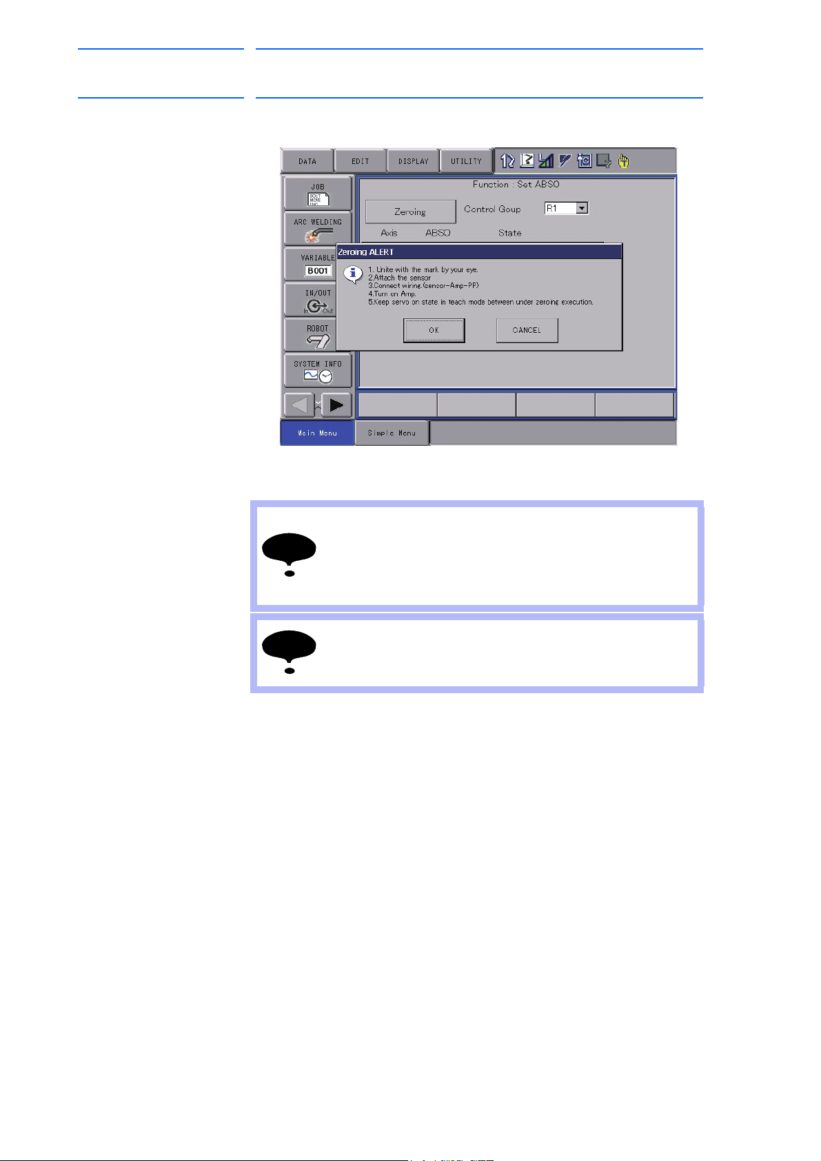
10. Press {Zeroing} on the touch panel, and pop-up window appears
displaying the CAUTION message.
11. Press {OK} by following the message in the pop-up window, and the
manipulator st
arts automatically.
Confirm that no persons are present in the P-point
maximum envelope of the manipulator and the operator is
in a safe place.
Injury may result from unintentional or unexpected
manipulator motion, or operation error.
The manipulator motion is hard to be detected due to its
slight motion.
Confirm that no person approach the manipulator.
1-8
HW1481050
Page 22

MH50/MH50-35/MH80/
NOTE
NOTE
NOTE
22 of 51
MS80 Zeroing
163471-1CD
1 Zeroing Function
1.2 Details on Zeroing Function
12. The programming pendant screen shows the message to confirm the
completion of the zeroing operation, then indicates the calculated
absolute data.
13. Turn OFF the servo power.
Be sure to turn OFF the servo power to approach the
manipulator.
Injury may result from unintentional or unexpected
manipulator motion.
14. Turn OFF the amplifier power.
15. Disconnect the lead wire from the sensor.
16. Remove the sensor from the manipulator.
After the zeroing operation, be sure to remove the sensor
from the manipulator before starting the manipulator.
If the manipulator is operated with the sensor attached to
the manipulator, the sensor may be damaged.
17. Reinstall the plug and cover onto the manipulator.
Be sure to install the plug and cover to prevent any dirt on
the sensor mounting holes or sensor detecting element.
The zeroing operation cannot be performed if any dirt is
attached on them.
1-9
HW1481050
Page 23

163471-1CD
NOTE
23 of 51
MH50/MH50-35/MH80/
MS80 Zeroing
1 Zeroing Function
1.2 Details on Zeroing Function
18. Remove dust on the sensor for the sensor dust.
19. Confirm the manipulator position as follows:
Select {Robot} from [Main Menu] → {Second Home Position}.
– The Second Home Position window appears.
–
For safety reasons, automatic operations by playback cannot be
performed unless the position is confirmed.
20. Turn ON the servo power by the [SER
Enable switch on the programming pendant.
Then, press [FWD] to move TCP to the second home position.
– Check for any position deviation of the manipulator’s second home
position.
21. Select {Data} from [Main Menu] → {Confirm Position}.
– The message “Home position checked” appears.
22. Confirm the operation in the “TEACH” mode before restarting
au
tomatic operation by playback.
– Check the followings to confirm the operation.
• Any deviation at each taught point by FWD operation in the
“TEACH” mode
• Test runs
Be sure to confirm the home position before starting
automatic operation.
If false home position is input by the zeroing function, it may
lead to errors in the manipulator performance.
VO ON READY] button and
1-10
HW1481050
Page 24

MH50/MH50-35/MH80/
L-axis
NOTE
NOTE
NOTE
NOTE
NOTE
24 of 51
MS80 Zeroing
1.2.2.4 Zeroing Procedure for L-Axis
163471-1CD
1 Zeroing Function
1.2 Details on Zeroing Function
Perform the zeroing operation for L-axis with the following procedure.
1. Remove the plug and cover from the attaching portion for the sensor.
Be sure to remove the cover. If the zeroing operation is
performed with the cover on, the sensor may be damaged.
The plug, cover, and cover mounting screws are small
parts.
Be sure not to lose them during the operation.
Be sure that the servo power is OFF and no safety hazard
is around the manipulator when approaching the
manipulator.
Injury may result from unintentional or unexpected
manipulator motion, or operation error.
2. Perform the home position alignment by adjusting the alignment marks
on the L-axis of the manipulator in the “TEACH” mode.
Be sure to adjust the home position alignment marks and
perform the zeroing operation.
Confirm that no persons are present in the P-point
maximum envelope of the manipulator and the operator is
in a safe place.
Injury may result from unintentional or unexpected
manipulator motion, or operation error.
3. Check that no spatter, fume or rust is attached in/on the sensor
mounting hole, or sensor detecting element after removing the plug
and cover.
– Remove the spatter, fume, and rust if they are found.
1-11
HW1481050
Page 25

163471-1CD
NOTE
NOTE
25 of 51
MH50/MH50-35/MH80/
MS80 Zeroing
1 Zeroing Function
1.2 Details on Zeroing Function
4. Install the sensor onto the mounting holes.
Never use tools, or avoid excessive force on the sensor.
Failure to observe this instruction may result in damage to
the sensor.
5. Connect the lead wire to the sensor.
6. Turn ON the amplifier power.
– If the amplifier power has been turned ON for prolonged periods of
tim
e, turn OFF the power once and turn ON the power again.
7. Set the mode selector switch on the programming pendant to
“TEA
CH”.
8. Select {Robot} → {Zeroing} from [Main Menu].
Then, select “L: L-axis” on the touch panel.
9. Turn ON the servo power by the [SER
Enable switch on the programming pendant.
Confirm that no persons are present in the P-point
maximum envelope of the manipulator and the operator is
in a safe place.
Injury may result from unintentional or unexpected
manipulator motion, or operation error.
1-12
VO ON READY] button and
HW1481050
Page 26
MH50/MH50-35/MH80/
NOTE
NOTE
26 of 51
MS80 Zeroing
163471-1CD
1 Zeroing Function
1.2 Details on Zeroing Function
10. Press {Zeroing} on the touch panel, and pop-up window appears
displaying the CAUTION message.
11. Press {OK} by following the message in the pop-up window, and the
anipulator starts automatically.
m
Confirm that no persons are present in the P-point
maximum envelope of the manipulator and the operator is
in a safe place.
Injury may result from unintentional or unexpected
manipulator motion, or operation error.
The manipulator motion is hard to be detected due to its
slight motion.
Confirm that no persons approach the manipulator.
1-13
HW1481050
Page 27

163471-1CD
NOTE
NOTE
NOTE
27 of 51
MH50/MH50-35/MH80/
MS80 Zeroing
1 Zeroing Function
1.2 Details on Zeroing Function
12. The programming pendant screen shows the message to confirm the
completion of the zeroing operation, then indicates the calculated
absolute data.
13. Turn OFF the servo power.
Be sure to turn OFF the servo power to approach the
manipulator.
Injury may result from unintentional or unexpected
manipulator motion.
14. Turn OFF the amplifier power.
15. Disconnect the lead wire from the sensor.
16. Remove the sensor from the manipulator.
After the zeroing operation, be sure to remove the sensor
from the manipulator before starting the manipulator.
If the manipulator is operated with the sensor attached to
the manipulator, the sensor may be damaged.
17. Reinstall the plug and cover onto the manipulator.
Be sure to install the plug and cover to prevent any dirt on
the sensor mounting holes or sensor detecting element.
The zeroing operation cannot be performed if any dirt is
attached on them.
1-14
HW1481050
Page 28
MH50/MH50-35/MH80/
NOTE
28 of 51
MS80 Zeroing
1 Zeroing Function
1.2 Details on Zeroing Function
18. Remove dust on the sensor for the sensor dust.
19. Confirm the manipulator position as follows:
Select {Robot} from [Main Menu] → {Second Home Position}.
– The Second Home Position window appears.
–
For safety reasons, automatic operations by playback cannot be
performed unless the position is confirmed.
163471-1CD
20. Turn ON the servo power by the [SER
Enable switch on the programming pendant.
Then, press [FWD] to move TCP to the second home position.
– Check for any position deviation of th
position.
21. Select {Data} from [Main Menu] → {Confirm Position}.
– The message “Home position checked” appears.
22. Confirm the operation in the “TEACH” mode before restarting
a
utomatic operation by playback.
– Check the followings to confirm the operation.
• Any deviation at each taught point by FWD operation in the
“TEACH” mode
• Test runs
Be sure to confirm the home position before starting
automatic operation.
If false home position is input by the zeroing function, it may
lead to errors in the manipulator performance.
VO ON READY] button and
e manipulator’s second home
1-15
HW1481050
Page 29

163471-1CD
U-axis
NOTE
NOTE
NOTE
NOTE
NOTE
29 of 51
MH50/MH50-35/MH80/
MS80 Zeroing
1.2.2.5 Zeroing Procedure for U-Axis
1 Zeroing Function
1.2 Details on Zeroing Function
Perform the zeroing operation for U-axis with the following procedure.
1. Remove the plug and cover from the attaching portion for the sensor.
Be sure to remove the cover. If the zeroing operation is
performed with the cover on, the sensor may be damaged.
The plug, cover, and cover mounting screws are small
parts, be sure not to lose them during the operation.
Be sure that the servo power is OFF and no safety hazard
is around the manipulator when approaching the
manipulator.
Injury may result from unintentional or unexpected
manipulator motion, or operation error.
2. Perform the home position alignment by adjusting the alignment marks
on the U-axis of the manipulator in the “TEACH” mode.
Be sure to adjust the home position alignment marks and
perform the zeroing operation.
Confirm that no persons are present in the P-point
maximum envelope of the manipulator and the operator is
in a safe place.
Injury may result from unintentional or unexpected
manipulator motion, or operation error.
3. Check that no spatter, fume or rust is attached in/on the sensor
mounting hole, or indentation after removing the plug and cover.
– Remove the spatter, fume, and rust if they are found.
1-16
HW1481050
Page 30

MH50/MH50-35/MH80/
NOTE
NOTE
30 of 51
MS80 Zeroing
163471-1CD
1 Zeroing Function
1.2 Details on Zeroing Function
4. Install the sensor onto the mounting holes.
Never use tools, or avoid excessive force on the sensor.
Failure to observe this instruction may result in damage to
the sensor.
5. Connect the lead wire to the sensor.
6. Turn ON the amplifier power.
– If the amplifier power has been turned ON for prolonged periods of
time, tu
7. Set the mode selector switch on the programming pendant to
“TEACH”.
8. Select {Robot}
Then, select “U: U-axis” on the touch panel.
rn OFF the power once and turn ON the power again.
→ {Zeroing} from [Main Menu].
9. Turn ON the servo power by the [SERVO ON READY] button and
able switch on the programming pendant.
En
Confirm that no persons are present in the P-point
maximum envelope of the manipulator and the operator is
in a safe place.
Injury may result from unintentional or unexpected
manipulator motion, or operation error.
1-17
HW1481050
Page 31

163471-1CD
NOTE
NOTE
31 of 51
MH50/MH50-35/MH80/
MS80 Zeroing
1 Zeroing Function
1.2 Details on Zeroing Function
10. Press {Zeroing} on the touch panel, and pop-up window appears
displaying the CAUTION message.
11. Press {OK} by following the message in the pop-up window, and the
manipulator st
arts automatically.
Confirm that no persons are present in the P-point
maximum envelope of the manipulator and the operator is
in a safe place.
Injury may result from unintentional or unexpected
manipulator motion, or operation error.
The manipulator motion is hard to be detected due to its
slight motion.
Confirm that no persons approach the manipulator.
1-18
HW1481050
Page 32
MH50/MH50-35/MH80/
NOTE
NOTE
NOTE
32 of 51
MS80 Zeroing
163471-1CD
1 Zeroing Function
1.2 Details on Zeroing Function
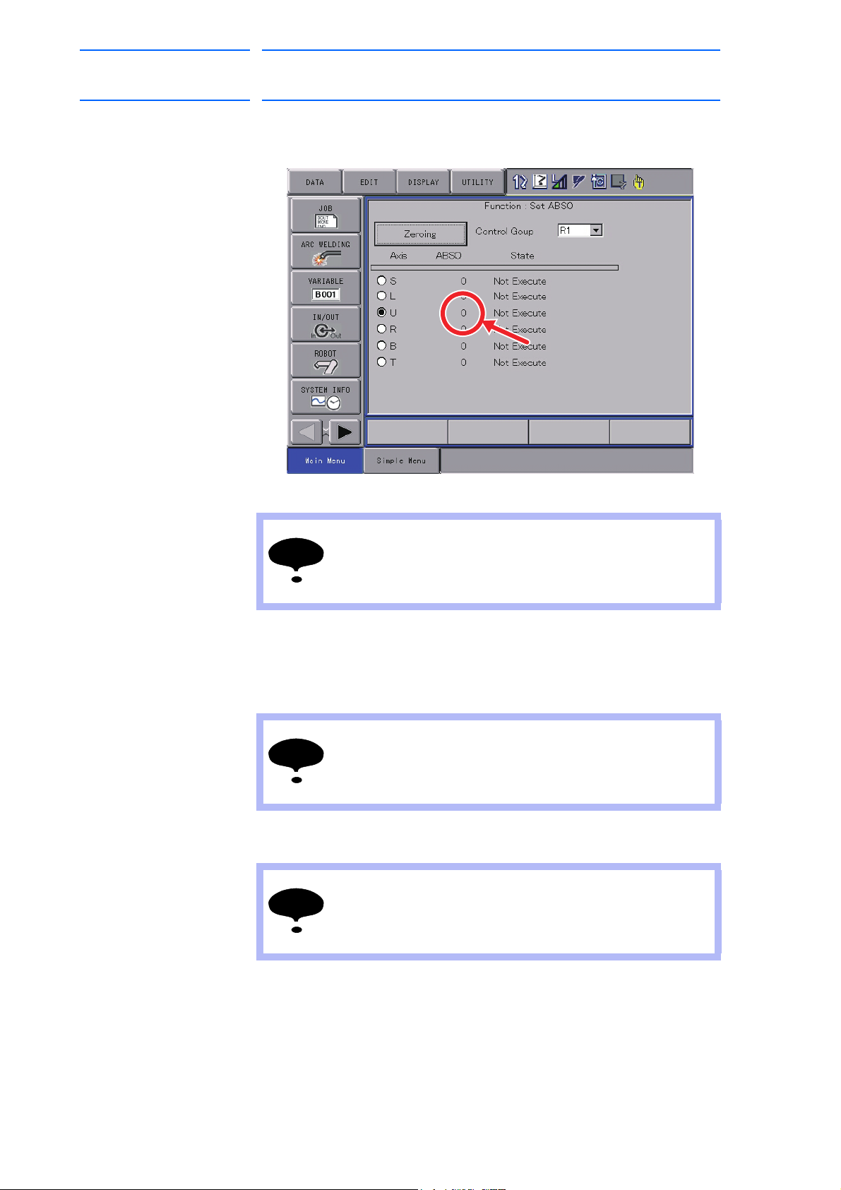
12. The programming pendant screen shows the message to confirm the
completion of the zeroing operation, then indicates the calculated
absolute data.
13. Turn OFF the servo power.
Be sure to turn OFF the servo power to approach the
manipulator.
Injury may result from unintentional or unexpected
manipulator motion.
14. Turn OFF the amplifier power.
15. Disconnect the lead wire from the sensor.
16. Remove the sensor from the manipulator.
After the zeroing operation, be sure to remove the sensor
from the manipulator before starting the manipulator.
If the manipulator is operated with the sensor attached to
the manipulator, the sensor may be damaged.
17. Reinstall the plug and cover onto the manipulator.
Be sure to install the plug and cover to prevent any dirt on
the sensor mounting holes or sensor detecting element.
The zeroing operation cannot be performed if any dirt is
attached on them.
1-19
HW1481050
Page 33

163471-1CD
NOTE
33 of 51
MH50/MH50-35/MH80/
MS80 Zeroing
1 Zeroing Function
1.2 Details on Zeroing Function
18. Remove dust on the sensor for the sensor dust.
19. Confirm the manipulator position as follows:
Select {Robot} from [Main Menu]
– The Second Home Position window appears.
–
For safety reasons, automatic operations by playback cannot be
performed unless the position is confirmed.
→ {Second Home Position}.
20. Turn ON the servo power by the [SER
Enable switch on the programming pendant.
Then, press [FWD] to move TCP to the second home position.
– Check for any position deviation of the manipulator’s second home
position.
21. Select {Data} from [Main Menu]
– The message “Home position checked” appears.
22. Confirm the operation in the “TEACH” mode before restarting
au
tomatic operation by playback.
– Check the followings to confirm the operation.
• Any deviation at each taught point by FWD operation in the
“TEACH” mode
• Test runs
Be sure to confirm the home position before starting
automatic operation.
If false home position is input by the zeroing function, it may
lead to errors in the manipulator performance.
VO ON READY] button and
→ {Confirm Position}.
1-20
HW1481050
Page 34

MH50/MH50-35/MH80/
NOTE
NOTE
NOTE
NOTE
NOTE
R-axis
34 of 51
MS80 Zeroing
1.2.2.6 Zeroing Procedure for R-Axis
163471-1CD
1 Zeroing Function
1.2 Details on Zeroing Function
Perform the zeroing operation for R-axis with the following procedure.
1. Remove the plug and cover from the attaching portion for the sensor.
Be sure to remove the cover. If the zeroing operation is
performed with the cover on, the sensor may be damaged.
The plug, cover, and cover mounting screws are small
parts.
Be sure not to lose them during the operation.
Be sure that the servo power is OFF and no safety hazard
is around the manipulator when approaching the
manipulator.
Injury may result from unintentional or unexpected
manipulator motion, or operation error.
2. Perform the home position alignment by adjusting the alignment marks
on the R-axis of the manipulator in the “TEACH” mode.
Be sure to adjust the home position alignment marks and
perform the zeroing operation.
Confirm that no persons are present in the P-point
maximum envelope of the manipulator and the operator in a
safe place.
Injury may result from unintentional or unexpected
manipulator motion, or operation error.
1-21
HW1481050
Page 35

163471-1CD
NOTE
35 of 51
MH50/MH50-35/MH80/
MS80 Zeroing
1 Zeroing Function
1.2 Details on Zeroing Function
3. Check that no spatter, fume or rust is attached in/on the sensor
mounting hole, or sensor detecting element after removing the plug
and cover.
– Remove the spatter, fume, and rust if they are found.
4. Install the sensor onto the mounting holes.
Never use tools, or avoid excessive force on the sensor.
Failure to observe this instruction may result in damage to
the sensor.
5. Connect the lead wire to the sensor.
6. Turn ON the amplifier power.
– If the amplifier power has been turned ON for prolonged periods of
tim
e, turn OFF the power once and turn ON the power again.
7. Set the mode selector switch on the programming pendant to
“TEA
CH”.
8. Select {Robot}
Then, select “R: R-axis” on the touch panel.
→ {Zeroing} from [Main Menu].
1-22
HW1481050
Page 36

MH50/MH50-35/MH80/
NOTE
NOTE
NOTE
36 of 51
MS80 Zeroing
163471-1CD
1 Zeroing Function
1.2 Details on Zeroing Function
9. Turn ON the servo power by the [SERVO ON READY] button and
Enable switch on the programming pendant.
Confirm that no persons are present in the P-point
maximum envelope of the manipulator and the operator is
in a safe place.
Injury may result from unintentional or unexpected
manipulator motion, or operation error.
10. Press {Zeroing} on the touch panel, and pop-up window appears
displaying the CAUTION message.
11. Press {OK} by following the message in the pop-up window, and the
manipulator starts automatically.
Confirm that no persons are present in the P-point
maximum envelope of the manipulator and the operator is
in a safe place.
Injury may result from unintentional or unexpected
manipulator motion, or operation error.
The manipulator motion is hard to be detected due to its
slight motion.
Confirm that no persons approach the manipulator.
1-23
HW1481050
Page 37

163471-1CD
NOTE
NOTE
NOTE
37 of 51
MH50/MH50-35/MH80/
MS80 Zeroing
1 Zeroing Function
1.2 Details on Zeroing Function
12. The programming pendant screen shows the message to confirm the
completion of the zeroing operation, then indicates the calculated
absolute data.
13. Turn OFF the servo power.
Be sure to turn OFF the servo power to approach the
manipulator.
Injury may result from unintentional or unexpected
manipulator motion.
14. Turn OFF the amplifier power.
15. Disconnect the lead wire from the sensor.
16. Remove the sensor from the manipulator.
After the zeroing operation, be sure to remove the sensor
from the manipulator before starting the manipulator.
If the manipulator is operated with the sensor attached to
the manipulator, the sensor may be damaged.
17. Reinstall the plug and cover onto the manipulator.
Be sure to install the plug and cover to prevent any dirt on
the sensor mounting holes or sensor detecting element.
The zeroing operation cannot be performed if any dirt is
attached on them.
1-24
HW1481050
Page 38

MH50/MH50-35/MH80/
NOTE
38 of 51
MS80 Zeroing
1 Zeroing Function
1.2 Details on Zeroing Function
18. Remove dust on the sensor for the sensor dust.
19. Confirm the manipulator position as follows:
Select {Robot} from [Main Menu]
– The Second Home Position window appears.
–
For safety reasons, automatic operations by playback cannot be
performed unless the position is confirmed.
→ {Second Home Position}.
163471-1CD
20. Turn ON the servo power by the [SER
Enable switch on the programming pendant.
Then, press [FWD] to move TCP to the second home position.
– Check for any position deviation of th
position.
21. Select {Data} from [Main Menu]
– The message “Home position checked” appears.
22. Confirm the operation in the “TEACH” mode before restarting
a
utomatic operation by playback.
– Check the followings to confirm the operation.
• Any deviation at each taught point by FWD operation in the
“TEACH” mode
• Test runs
Be sure to confirm the home position before starting
automatic operation.
If false home position is input by the zeroing function, it may
lead to errors in the manipulator performance.
VO ON READY] button and
e manipulator’s second home
→ {Confirm Position}.
1-25
HW1481050
Page 39

163471-1CD
B-axis
NOTE
NOTE
NOTE
NOTE
NOTE
39 of 51
MH50/MH50-35/MH80/
MS80 Zeroing
1.2.2.7 Zeroing Procedure for B-Axis
1 Zeroing Function
1.2 Details on Zeroing Function
Perform the zeroing operation for B-axis with the following procedure.
1. Remove the plug and cover from the attaching portion for the sensor.
Be sure to remove the cover. If the zeroing operation is
performed with the cover on, the sensor may be damaged.
The plug, cover, and cover mounting screws are small
parts.
Be sure not to lose them during the operation.
Be sure that the servo power is OFF and no safety hazard
is around the manipulator when approaching the
manipulator.
Injury may result from unintentional or unexpected
manipulator motion, or operation error.
2. Perform the home position alignment by adjusting the alignment marks
on the B-axis of the manipulator in the “TEACH” mode.
Be sure to adjust the home position alignment marks and
perform the zeroing operation.
Confirm that no persons are present in the P-point
maximum envelope of the manipulator and the operator is
in a safe place.
Injury may result from unintentional or unexpected
manipulator motion, or operation error.
3. Check that no spatter, fume or rust is attached in/on the sensor
mounting hole, or sensor detecting element after removing the plug
and cover.
– Remove the spatter, fume, and rust if they are found.
1-26
HW1481050
Page 40

MH50/MH50-35/MH80/
NOTE
NOTE
40 of 51
MS80 Zeroing
163471-1CD
1 Zeroing Function
1.2 Details on Zeroing Function
4. Install the sensor onto the mounting holes.
Never use tools, or avoid excessive force on the sensor.
Failure to observe this instruction may result in damage to
the sensor.
5. Connect the lead wire to the sensor.
6. Turn ON the amplifier power.
– If the amplifier power has been turned ON for prolonged periods of
time, tu
7. Set the mode selector switch on the programming pendant to
“TEACH”.
8. Select {Robot}
Then, select “B: B-axis” on the touch panel.
rn OFF the power once and turn ON the power again.
→ {Zeroing} from [Main Menu].
9. Turn ON the servo power by the [SERVO ON READY] button and
able switch on the programming pendant.
En
Confirm that no persons are present in the P-point
maximum envelope of the manipulator and the operator is
in a safe place.
Injury may result from unintentional or unexpected
manipulator motion, or operation error.
1-27
HW1481050
Page 41

163471-1CD
NOTE
NOTE
41 of 51
MH50/MH50-35/MH80/
MS80 Zeroing
1 Zeroing Function
1.2 Details on Zeroing Function
10. Press {Zeroing} on the touch panel, and pop-up window appears
displaying the CAUTION message.
11. Press {OK} by following the message in the pop-up window, and the
manipulator st
arts automatically.
Confirm that no persons are present in the P-point
maximum envelope of the manipulator and the operator is
in a safe place.
Injury may result from unintentional or unexpected
manipulator motion, or operation error.
The manipulator motion is hard to be detected due to its
slight motion.
Confirm that no persons approach the manipulator.
1-28
HW1481050
Page 42

MH50/MH50-35/MH80/
NOTE
NOTE
NOTE
42 of 51
MS80 Zeroing
163471-1CD
1 Zeroing Function
1.2 Details on Zeroing Function
12. The programming pendant screen shows the message to confirm the
completion of the zeroing operation, then indicates the calculated
absolute data.
13. Turn OFF the servo power.
Be sure to turn OFF the servo power to approach the
manipulator.
Injury may result from unintentional or unexpected
manipulator motion.
14. Turn OFF the amplifier power.
15. Disconnect the lead wire from the sensor.
16. Remove the sensor from the manipulator.
After the zeroing operation, be sure to remove the sensor
from the manipulator before starting the manipulator.
If the manipulator is operated with the sensor attached to
the manipulator, the sensor may be damaged.
17. Reinstall the plug and cover onto the manipulator.
Be sure to install the plug and cover to prevent any dirt on
the sensor mounting holes or sensor detecting element.
The zeroing operation cannot be performed if any dirt is
attached on them.
1-29
HW1481050
Page 43

163471-1CD
NOTE
43 of 51
MH50/MH50-35/MH80/
MS80 Zeroing
1 Zeroing Function
1.2 Details on Zeroing Function
18. Remove dust on the sensor for the sensor dust.
19. Confirm the manipulator position as follows:
Select {Robot} from [Main Menu]
– The Second Home Position window appears.
–
For safety reasons, automatic operations by playback cannot be
performed unless the position is confirmed.
→ {Second Home Position}.
20. Turn ON the servo power by the [SER
Enable switch on the programming pendant.
Then, press [FWD] to move TCP to the second home position.
21. Check for any position deviation of the manipulator’s second home
sition.
po
22. Select {Data} from [Main Menu]
– The message “Home position checked” appears.
23. Confirm the operation in the “TEACH” mode before restarting
au
tomatic operation by playback.
– Check the followings to confirm the operation.
• Any deviation at each taught point by FWD operation in the
“TEACH” mode
• Test runs
Be sure to confirm the home position before starting
automatic operation.
If false home position is input by the zeroing function, it may
lead to errors in the manipulator performance.
VO ON READY] button and
→ {Confirm Position}.
1-30
HW1481050
Page 44

MH50/MH50-35/MH80/
NOTE
NOTE
NOTE
NOTE
NOTE
T-axis
44 of 51
MS80 Zeroing
1.2.2.8 Zeroing Procedure for T-Axis
163471-1CD
1 Zeroing Function
1.2 Details on Zeroing Function
Perform the zeroing operation for T-axis with the following procedure.
1. Remove the plug and cover from the attaching portion for the sensor.
Be sure to remove the cover. If the zeroing operation is
performed with the cover on, the sensor may be damaged.
The plug, cover, and cover mounting screws are small
parts.
Be sure not to lose them during the operation.
Be sure that the servo power is OFF and no safety hazard
is around the manipulator when approaching the
manipulator.
Injury may result from unintentional or unexpected
manipulator motion, or operation error.
2. Perform the home position alignment by adjusting the alignment marks
on the T-axis of the manipulator in the “TEACH” mode.
Be sure to adjust the home position alignment marks and
perform the zeroing operation.
Confirm that no persons are present in the P-point
maximum envelope of the manipulator and the operator is
in a safe place.
Injury may result from unintentional or unexpected
manipulator motion, or operation error.
3. Check that no spatter, fume or rust is attached in/on the sensor
mounting hole, or sensor detecting element after removing the plug
and cover.
– Remove the spatter, fume, and rust if they are found.
1-31
HW1481050
Page 45

163471-1CD
NOTE
NOTE
45 of 51
MH50/MH50-35/MH80/
MS80 Zeroing
1 Zeroing Function
1.2 Details on Zeroing Function
4. Install the sensor onto the mounting holes.
Never use tools, or avoid excessive force on the sensor.
Failure to observe this instruction may result in damage to
the sensor.
5. Connect the lead wire to the sensor.
6. Turn ON the amplifier power.
– If the amplifier power has been turned ON for prolonged periods of
tim
e, turn OFF the power once and turn ON the power again.
7. Set the mode selector switch on the programming pendant to
“TEA
CH”.
8. Select {Robot}
Then, select “T: T-axis” on the touch panel.
→ {Zeroing} from [Main Menu].
9. Turn ON the servo power by the [SER
Enable switch on the programming pendant.
Confirm that no persons are present in the P-point
maximum envelope of the manipulator and the operator is
in a safe place.
Injury may result from unintentional or unexpected
manipulator motion, or operation error.
1-32
VO ON READY] button and
HW1481050
Page 46

MH50/MH50-35/MH80/
NOTE
NOTE
46 of 51
MS80 Zeroing
163471-1CD
1 Zeroing Function
1.2 Details on Zeroing Function
10. Press {Zeroing} on the touch panel, and pop-up window appears
displaying the CAUTION message.
11. Press {OK} by following the message in the pop-up window, and the
anipulator starts automatically.
m
Confirm that no persons are present in the P-point
maximum envelope of the manipulator and the operator is
in a safe place.
Injury may result from unintentional or unexpected
manipulator motion, or operation error.
The manipulator motion is hard to be detected due to its
slight motion.
Confirm that no persons approach the manipulator.
1-33
HW1481050
Page 47
163471-1CD
NOTE
NOTE
NOTE
47 of 51
MH50/MH50-35/MH80/
MS80 Zeroing
1 Zeroing Function
1.2 Details on Zeroing Function
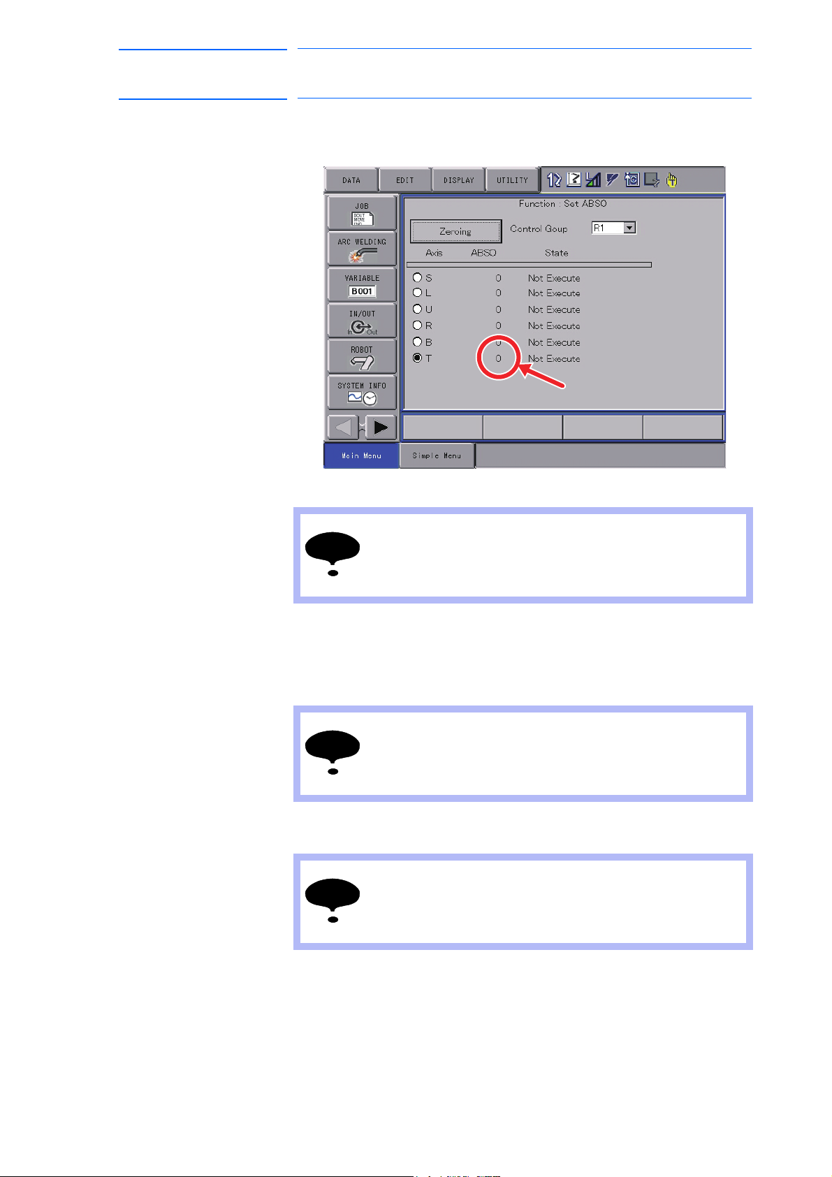
12. The programming pendant screen shows the message to confirm the
completion of the zeroing operation, then indicates the calculated
absolute data.
13. Turn OFF the servo power.
Be sure to turn OFF the servo power to approach the
manipulator.
Injury may result from unintentional or unexpected
manipulator motion.
14. Turn OFF the amplifier power.
15. Disconnect the lead wire from the sensor.
16. Remove the sensor from the manipulator.
After the zeroing operation, be sure to remove the sensor
from the manipulator before starting the manipulator.
If the manipulator is operated with the sensor attached to
the manipulator, the sensor may be damaged.
17. Reinstall the plug and cover onto the manipulator.
Be sure to install the plug and cover to prevent any dirt on
the sensor mounting hoes or sensor detecting element.
The zeroing operation cannot be performed if any dirt is
attached on them.
1-34
HW1481050
Page 48

MH50/MH50-35/MH80/
NOTE
48 of 51
MS80 Zeroing
1 Zeroing Function
1.2 Details on Zeroing Function
18. Remove dust on the sensor for the sensor dust.
19. Confirm the manipulator position as follows:
Select {Robot} from [Main Menu]
– The Second Home Position window appears.
–
For safety reasons, automatic operations by playback cannot be
performed unless the position is confirmed.
→ {Second Home Position}.
163471-1CD
20. Turn ON the servo power by the [SER
Enable switch on the programming pendant.
Then, press [FWD] to move TCP to the second home position.
– Check for any position deviation of th
position.
21. Select {Data} from [Main Menu] → {Confirm Position}.
– The message “Home position checked” appears.
22. Confirm the operation in the “TEACH” mode before restarting
a
utomatic operation by playback.
– Check the followings to confirm the operation.
• Any
deviation at each taught point by FWD operation in the
“TEACH” mode
• Test runs
Be sure to confirm the home position before starting
automatic operation.
If false home position is input by the zeroing function, it may
lead to errors in the manipulator performance.
VO ON READY] button and
e manipulator’s second home
1-35
HW1481050
Page 49

163471-1CD
49 of 51
MH50/MH50-35/MH80/
MS80 Zeroing
1 Zeroing Function
1.3 Errors in the Zeroing Operation and Solutions
1.3 Errors in the Zeroing Operation and Solutions
If errors occur during the zeroing operation, confirm the error contents and
perform the following operations.
Message Contents Operation
There is little depth of the hole or it
is large.
Investigate the hole.
ErrorCode:55550004
Switch mode to teach.
Again, Execute zeroing.
Keep servo on state in teach mode
between under zeroing execution.
Again, Execute zeroing
Loop Error [The maximum
measurement point were
exceeded.]
ErrorCode:55550005
Loop Error [Acquiring a pulse went
wrong.]
ErrorCode:55550006
Loop Error [The processing which
starts robot operation went wrong.]
ErrorCode:55550008
Loop Error [The processing which
stops robot operation went wrong.]
ErrorCode:55550009
Loop Error [Acquiring the value of
the sensor went wrong.]
ErrorCode:55550010
Error [Sensor Amp (Read():D1)]
ErrorCode:55550044
Information
* Check the amp power supply of
the sensor.
* Check connection of the RS232C cable.
* Check Battery.
Alarm : Sensor Amp (Battery) Amplifier battery exhaustion Replace the battery with the new
Alarm : Sensor Amp (Write Error
EEPROM)
Error in the data on the hole depth
caught by the sensor
The mode selector switch on the
programming pendant is set to “PLAY”
mode at the start of the zeroing
operation.
The servo power is not turned ON at
the start of the zeroing operation.
Error in the zeroing processing Possible causes: False parameter
Error in communication Possible causes: Inconsistency in
Error in communication Contact your nearest YASKAWA
Error in communication Check if the alarm lamp is lit,
Amplifier EEPROM writing error Contact your nearest YASKAWA
Check if dust or spatter is
present on the hole.
Check for damage or cracks
on the sensor exterior, or
deformation of the sensor
end.
Perform the zeroing
operation again upon
confirming the procedures.
Set the mode selector switch to
“TEACH” to perform the zeroing
operation.
Turn ON the servo power by the
operations as gripping the Enable
switch of the programming
pendant, etc.
settings for zeroing speed,
distance, radius, and etc., false
starting point of the zeroing
operation and etc.
Contact the nearest YASKAWA
representative.
software version.
Contact your nearest YASKAWA
representative.
representative for perceiving the
details on the current state by the
particular numbers.
Contact your nearest YASKAWA
representative.
or cables and etc. are
connected properly.
Turn OFF the power to the
amplifier, and turn ON again.
Then perform the zeroing
operation.
battery.
representative.
1-36
HW1481050
Page 50

163471-1CD
50 of 51
MH50/MH50-35/MH80/
MS80 Zeroing
Message Contents Operation
Alarm : Sensor Amp (AD Over) AD Over Alarm of the amplifier Contact your nearest YASKAWA
Error [Sensor Amp (Auto
Zero:OK)]
ErrorCode:55550046
Error [No CtrlGroup]
ErrorCode:55550052
Error [No Axis]
ErrorCode:55550056
Not Found : RS-232C CF-Card
ErrorCode:55550001
Error [RS-232C Communication]
ErrorCode:55550017
Error [RS-232C Communication]
ErrorCode:55550018
Error RS-232C Communication]
ErrorCode:55550019
Error [RS-232C Communication]
ErrorCode:55550020
Error Occur The zeroing operation is terminated
Finish! (Error Occur)
Operator Stop The zeroing operation is terminated
Finish! (Operator Stop)
The operator pushed the stop.
Error [Any axis don't set ABSO.]
ErrorCode:55550088
Loop Error [The maximum moving
pulse over.]
ErrorCode:55550097
1 Zeroing Function
1.3 Errors in the Zeroing Operation and Solutions
representative.
Error in zeroing of the amplifier Contact your nearest YASKAWA
representative.
Zeroing was performed with the DX100
which has no manipulator control
group.
Zeroing was performed with the
manipulator control group which has no
operable axes.
CF-Card for the RS-232C is not
inserted into the slot of the
programming pendant.
Errors occur during the amplifier
communication
due to error occurrence.
with the stop button.
Error in the zeroing processing Contact your nearest YASKAWA
Error in the zeroing processing Contact your nearest YASKAWA
Perform the zeroing operation by
the DX100 with the manipulator
control group.
Specify the manipulator control
group with operable axes.
Insert the CF-Card for the RS232C into the slot.
Contact your nearest YASKAWA
representative.
Confirm the error content and
remove the error cause. Then,
perform the zeroing operation
again from the start.
Perform the zeroing operation
again from the start.
representative.
representative.
1-37
HW1481050
Page 51

HEAD OFFICE
2-1 Kurosakishiroishi, Yahatanishi-ku, Kitakyushu 806-0004, Japan
Phone +81-93-645-7703 Fax +81-93-645-7802
100 Automation Way, Miamisburg, OH 45342, U.S.A.
Phone +1-937-847-6200 Fax +1-937-847-6277
YASKAWA America Inc. (Motoman Robotics Division)
Yaskawastrasse 1, 85391 Allershausen, Germany
Phone +49-8166-90-100 Fax +49-8166-90-103
YASKAWA Europe GmbHRobotics Divsion )
Phone +82-2-784-7844 Fax +82-2-784-8495
151 Lorong Chuan, #04-02A, New Tech Park, Singapore 556741
Phone +65-6282-3003 Fax +65-6289-3003
YASKAWA Electric (Singapore) PTE Ltd.
No7 Yongchang North Road, Beijing E&T Development AreaChina 100176
Phone +86-10-6788-2858 Fax +86-10-6788-2878
YASKAWA SHOUGANG ROBOT Co. Ltd.
#426, Udyog Vihar, Phase- IV,Gurgaon, Haryana, India
Fax +91-124-475-8542Phone +91-124-475-8500
YASKAWA India Private Ltd. (Robotics Division)
YASKAWA Electric (China) Co., Ltd.
22F, One Corporate Avenue, No.222, Hubin Road, Huangpu District, Shanghai 200021, China
Phone +86-21-5385-2200 Fax 㸩86-21-5385-3299
YASKAWA Electric (Thailand) Co., Ltd.
59,1st-5th Floor, Flourish Building, Soi Ratchadapisek 18,Ratchadapisek Road,
Huaykwang, Bangkok 10310, THAILAND
Phone +66-2-017-0099 Fax +66-2-017-0199
12F, No.207, Sec. 3, Beishin Rd., Shindian District, New Taipei City 23143, Taiwan
Fax +886-2-8913-1513Phone +886-2-8913-1333
YASKAWA Electric Taiwan Corporation
Secure Building-Gedung B Lantai Dasar & Lantai 1 JI. Raya Protokol Halim Perdanakusuma,
Jakarta 13610, Indonesia
Fax +62-21-2982-6741Phone +62-21-2982-6470
PT. YASKAWA Electric Indonesia
Phone +46-480-417-800 Fax +46-486-414-10
YASKAWA Nordic AB
Verkstadsgatan 2, Box 504 ,SE-385 25 Torsas, Sweden
35F, Three IFC, 10 Gukjegeumyung-ro, Yeongdeungpo-gu, Seoul, Korea 07326
YASKAWA Electric Korea Corporation
MOTOMAN-MH50/ MH50-35/ MH80/ MS80
51 of 51
OPTIONS
INSTRUCTIONS
FOR ZEROING FUNCTION
Specifications are subject to change without notice
for ongoing product modifications and improvements.
MANUAL NO.
HW1481050
3
 Loading...