

Page 1
YASNAC
LX
3
FOR
TURNING
APPLICATIONS
COMPACT
PROGRAMMING
FUNCTION
OPERATOR’S
MANUAL
Sci\
1
?f?i
fei
tea
r
.
a
1
r;r
3*8
rf;
I]
,V
$
%
1
gf
K
•SSI
K
:•
Wi
i<
a
b
Before
initial
operation,
read
these
instructions
thoroughly,
and
retain
for
future
reference.
YASKAWA
Page 2
This
manual
describes
the
operator
procedures
for
“Compact
Programming
Function”
which
is
an
option¬
al
function
for
YASNAC
LX3.
For
the
operator
procedures
for
the
basic
con¬
trol,
refer
to
the
manual
“YASNAC
LX3
Operation
Manual”.
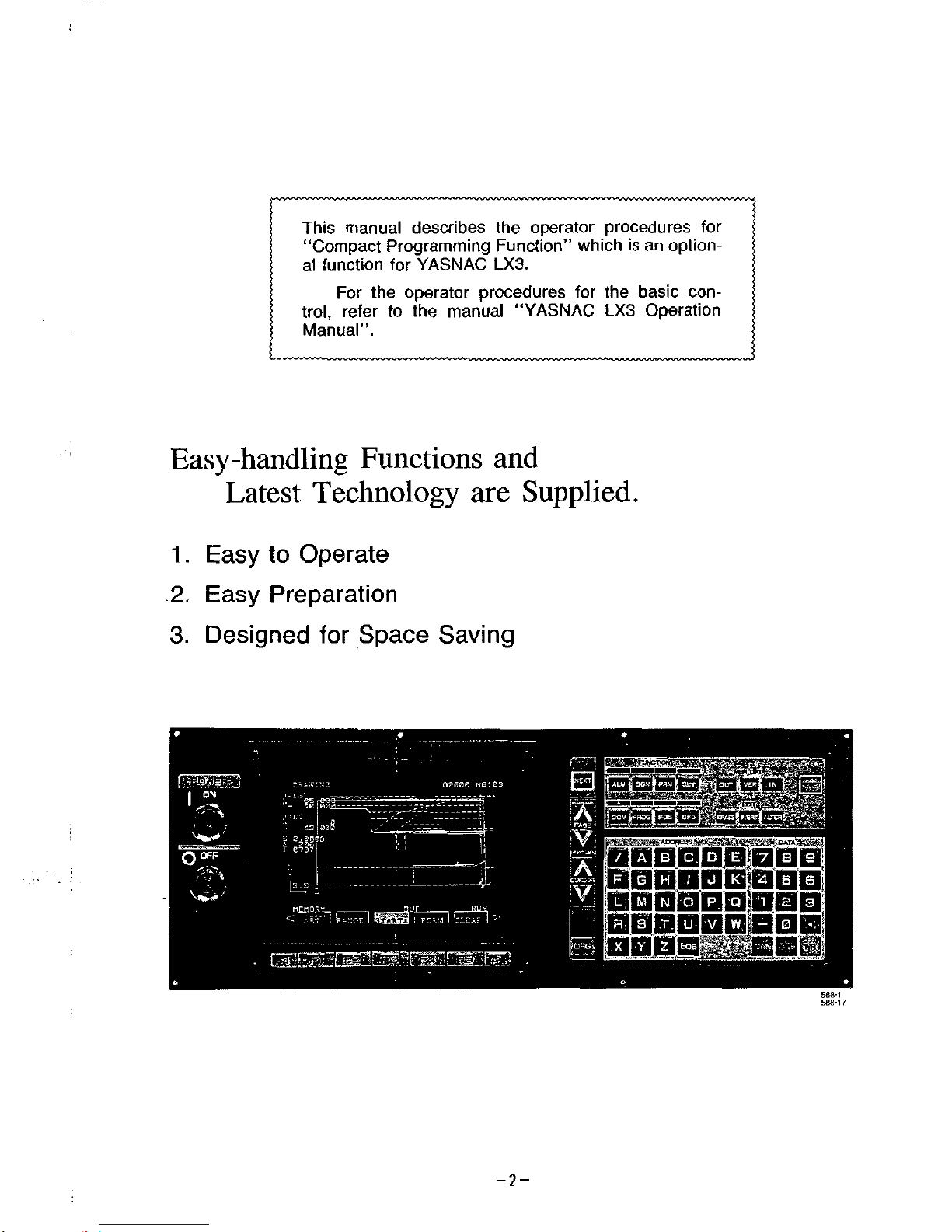
Easy-handling
Functions
and
Latest
Technology
are
Supplied.
1
.
Easy
to
Operate
2.
Easy
Preparation
3.
Designed
for
Space
Saving
r_.
EU
&
mm
m
02000
N6103
|
ON
5;
00°
i
mr
m
utiamM
0°FF
4
IA
_
JL
m
IL8:'
iOOQQQllOOj
n
"?Wr\
s£?1
m
588*1
586*1
i
-2-
Page 3
CONTENTS
1.
FUNCTION
OUTLINES
AND
FEATURES
2.
NC
OPERATOR
PANEL
AND
DISPLAY
2.1
NC
OPERATOR
PANEL
FUNCTION
OUTLINES
2.2
DISPLAY
IMMEDIATELY
AFTER
TURNING
POWER
ON
2.3
CONSTANT
DISPLAY
MESSAGES
2.4
FUNCTION
DISPLAY
7
8
8
14
15
18
3.
INTERACTIVE
PROGRAMMING
3.1
NC
UNIT
INTERNAL
CONFIGURATION
AND
FLOW
OF
INTERACTIVE
PROCESSES
3.2
CALL
UP
OF
INTERACTIVE
MODE
3.3
PROGRAM
NO.
SETTING
(FOR
NEW
DATA)
3.4
SETTING
BLANK
SHAPE
3.5
SETTING
BY
VARIABLE
TURNING
MENU
3.6
SETTING
WITH
DETAILED
TURNING
MENU
(ROUGHING,
FINISHING)
3.7
SETTING
OF
APPROACH
3.8
SETTING
OF
BASIC
DATA
3.9
SETTING
FINISH
SHAPE
3.10
PROGRAM
INSERTION
'
3.11
ESCAPE
SETTING
3.12
ESCAPE
FROM
INTERACTIVE
MODE
3.13
PRECAUTIONS
3.14
MESSAGES
IN
INTERACTIVE
MODE
3.15
FINISH
TURNING
EXECUTED
WITH
NC
COMPACT
PROGRAMMING
FUNCTIONS
4
CALCULATION
FUNCTION
4.1
INTERSECTION
POINT
OF
LINE
AND
LINE
4.2
INTERSECTION
POINTS
OF
LINE
AND
CIRCLE
4.3
CONTACT
POINTS
OF
LINE
INTERSECTING
ONE
POINT
AND
A
CIRCLE
4.4
CONTACT
POINTS
OF
LINE
OF
THE
SPECIFIED
ANGLE
AND
CIRCLE
4.5
CONTACT
POINTS
OF
A
LINE
THAT
CONTACTS
TWO
CIRCLE
4.6
INTERSECTION
POINTS
OF
CIRCLE
AND
CIRCLE
4.7
CONTACT
POINTS
OF
CIRCLE
THAT
INTERSECTS
ONE
POINT
AND
CONTACTS
A
LINE
—
129
4.8
CONTACT
POINTS
OF
CIRCLE
CONTACTING
A
LINE
AND
CIRCLE
4.9
CONTACT
POINTS
OF
CIRCLE
CONTACTING
TWO
LINES
4.10
CONTACT
POINTS
OF
CIRCLE
THAT
INTERSECTS
ONE
POINT
AND
CONTACTS
CIRCLE-
-
132
4.11
CONTACT
POINTS
OF
CIRCLE
CONTACTING
WITH
TWO
CIRCLES
4.12
CENTER
POINT
AND
RADIUS
OF
A
CIRCLE
THAT
INTERSECTS
POINTS
5.
PROGRAM
MODIFICATION
5.1
PREPARATIONS
FOR
MODIFICATION
5.2
MODIFICATION
PROCEDURE
5.3
ENDING
THE
PROGRAM
MODIFICATION
6.
DRAWING
OF
PROGRAMMING
6.1
SETTING
1
6.2
SETTING
OF
DRAWING
PROGRAM
6.3
HOW
TO
ENTER
THE
DRAWING
MODE
6.4
MATERIAL
SETTING
6.5
CLEARING
THE
DRAWING
6.6
SHAPE
..
6.7
START
OF
DRAWING
6.8
SETTING
THE
DRAWING
AREA
6.9
SETTING
2(DRAWING
END
OPERATION)
7.
OPERATION
OF
A
GENERATED
PROGRAM
8.
OPERATION
OF
INTERACTIVE
PARAMETERS
8.1
HOW
TO
ENTER
THE
INTERACTIVE
PARAMETERS
DISPLAY
8.2
SETTING
THE
INTERACTIVE
PARAMETERS
9.
INTERACTIVE
PARAMETER
LIST
39
39
41
41
43
45
46
51
55
57
81
82
84
84
87
89
118
119
123
124
125
126
128
130
131
133
135
136
136
136
142
143
144
144
146
-•
148
150
151
151
153
155
156
157
157
157
160
-3-
Page 4
:
:
INDEX
Chapter
Section
No.
Subject
C
CALCULATION
FUNCTION
CALL
UP
OF
INTERACTIVE
MODE
.
CENTER
POINT
AND
RADIUS
OF
A
CIRCLE
THAT
INTERSECTS
POINTS
CLEARING
THE
DRAWING
Common
mode
display
CONSTANT
DISPLAY
MESSAGES
CONTACT
POINTS
OF
A
LINE
THAT
CONTACTS
TWO
CIRCLES
-
CONTACT
POINTS
OF
CIRCLE
CONTACTING
A
LINE
AND
CIRCLE
CONTACT
POINTS
OF
CIRCLE
CONTACTING
TWO
LINES
CONTACT
POINTS
OF
CIRCLE
CONTACTING
WITH
TWO
CIRCLES
CONTACT
POINTS
OF
CIRCLE
THAT
INTERSECTS
ONE
POINT
AND
CONTACTS
A
LINE
4
CONTACT
POINTS
OF
CIRCLE
THAT
INTERSECTS
ONE
POINT
AND
CONTACTS
CIRCLE
CONTACT
POINTS
OF
LINE
INTERSECTING
ONE
POINT
AND
A
CIRCLE
4
CONTACT
POINTS
OF
LINE
OF
THE
SPECIFIED
ANGLE
AND
CIRCLE
4
D
Deleting
Process
Display
by
CDGN
)
(DIAGNOSIS)
FUNCTION
Key
Display
by
means
of
(PRM
)
FUNCTION
Key
Display
by
the
use
of
[SET
)
FUNCTION
Key
Display
for
Interactive
Parameters
#30
to
#39
Display
for
Interactive
Parameters
#40
to
tt
49
Display
for
Interactive
Parameters
#50
to
#59
Display
for
Interactive
Parameters
#60
to
#69
DISPLAY
IMMEDIATELY
AFTER
TURNING
POWER
ON
Display
with
(ALM
)
FUNCTION
Key
Display
with
(COM
)
(COMMAND)
FUNCTION
Key
Display
with
(OFS
)
FUNCTION
Key
Display
with
(POS
)
FUNCTION
Key
Display
by
(PROG)
(PROGRAM)
FUNCTION
Key
Drawing
DRAWING
OF
PROGRAMMING
Drilling
Drilling
Setting
E
EDIT
mode
ENDING
THE
PROGRAM
MODIFICATION
ESCAPE
FROM
INTERACTIVE
MODE
Page
118
4
3
3.2
4
......
4.12
6
6.5
2
......
2.4.6.
1
41
;
135
150
27
2
2.3
15
126
4
4.5
130
4
4.8
4.9
131
4
4
4.11
133
4.7
129
4.10
132
4
4.3
124
4.4
14
5
......
5.
2.2.
3
2
......
2.4.2
2
......
2.4.3
•
2
......
2.4.4
8
......
8.2.2
•
140
19
20
23
158
8
8
2
3
8.2.4
8.2.5
158
159
8
8
159
2
2.2
14
2.4.1
18
2
2
......
24.5
2
......
2.4.8
2
......
2.4.7
2
......
2.4.6
3
......
3.15.2
25
38
37
26
117
6
143
3
3.15.2
3.9.3
89
3
77
2
2.
4.
6.
2
29
5
5.3
142
3
......
3.12
84
3
......
3.12.2
84
Escape
from
Interactive
Mode
during
Program
Creation
ESCAPE
SETTING
3.11
3
82
3
......
3.15.6
3
......
3.9
2 2
3
......
3
15.3
3
......
3.15
107
F
Face
Finish
Turning
Face
Groove
Turning
Face
Rough
Turning
FINISH
TURNING
EXECUTED
WITH
NC
COMPACT
PROGRAMMING
FUNCTION
73
91
88
2
2.4
18
FUNCTION
DISPLAY
FUNCTION
OUTLINES
AND
FEATURES
1
/
3
......
3.13.5
3
......
3.15.10
3
......
3.15
9
G
Generated
NC
Statements
Groove
Finish
Turning
Groove
Rough
Turning
H
HOW
TO
ENTER
THE
DRAWING
MODE
HOW
TO
ENTER
THE
INTERACTIVE
PARAMETERS
DISPLAY
86
114
111
6
6.3
8
8.1
146
157
-4-
Page 5
INDEX
(Cont'd)
Subject
I/O
signal
selective
display
function
Initialization
Inner
Diameter
O.D.
Grooving
inner
Diameter
(I.D.)
Finish
Turmg
inner
Diameter
(I.D.)
Rough
Turnig
Inserting
a
Process
(mod
ify/i
risert
mode
is
used.)
Interactive
Data
Search
Timing
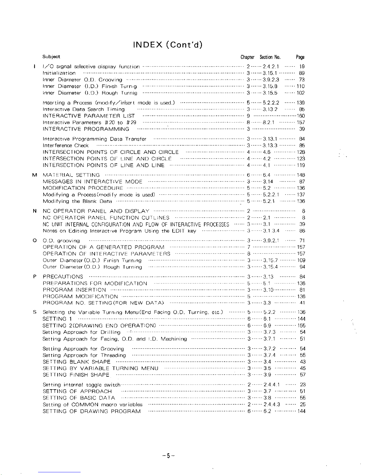
INTERACTIVE
PARAMETER
LIST
Interactive
Parameters
#20
to
#29
INTERACTIVE
PROGRAMMING
•ÿÿÿ
Chapter
Section
No.
2
......
2.4.2.
1
3
......
3.15.1
•
3
......
3.
9.2.3
3
......
3.15.8
3
......
3.15.5
Page
I
19
89
73
110
102
5
......
5.
2.2.2
3
......
3.13
2
139
85
160
9
8.2.1
157
8
3
39
3
......
3.13.1
3
......
3.13.3
84
Interactive
Programming
Data
Transfer
Interference
Check
INTERSECTION
POINTS
OF
CIRCLE
AND
CIRCLE
INTERSECTION
POINTS
OF
LINE
AND
CIRCLE
INTERSECTION
POINTS
OF
LINE
AND
LINE
85
4.6
128
4
123
4
4.2
119
4
4.1
M
MATERIAL
SETTING
MESSAGES
IN
INTERACTIVE
MODE
MODIFICATION
PROCEDURE
Modifying
a
Process
(modify
mode
is
used)
Modifying
the
Blank
Data
N
NC
OPERATOR
PANEL
AND
DISPLAY
NC
OPERATOR
PANEL
FUNCTION
OUTLINES
NC
UNIT
INTERNAL
CONFIGURATION
AND
FLOW
OF
INTERACTIVE
PROCESSES
......
3
......
3.1
39
Notes
on
Editing
Interactive
Program
Using
the
EDIT
key
O
O.D.
grooving
OPERATION
OF
A
GENERATED
PROGRAM
OPERATION
OF
INTERACTIVE
PARAMETERS
Outer
Diameter(O.D.)
Finish
Turning
Outer
Diameter
(O.D.)
Rough
Turning
P
PRECAUTIONS
PREPARATIONS
FOR
MODIFICATION
PROGRAM
INSERTION
PROGRAM
MODIFICATION
PROGRAM
NO.
SETTING
(FOR
NEW
DATA)
S
Selecting
the
Variable
Turning
Menu(End
Facing
O.D.
Turning,
etc.)
SETTING
1
SETTING
2(DRAWING
END
OPERATION)
Setting
Approach
for
Drilling
Setting
Approach
for
Facing,
O.D.
and
I.D.
Machining
Setting
Approach
for
Grooving
Setting
Approach
for
Threading
SETTING
BLANK
SHAPE
SETTING
BY
VARIABLE
TURNING
MENU
SETTING
FINISH
SHAPE
6
6.4
148
3
......
3.14
87
5
5.2
136
5.2.2.
1
137
5
5
5.2.1
136
2
8
2
2.1
8
3
3.1
3.4
86
.......
3
......
3.9.2.
1
71
7
157
8
157
3
......
3.15.7
3
......
3.15.4
109
94
3
......
3.13
84
136
5 5
1
3.10
81
3
5
136
3
3.3
41
5
......
5.2.2
6
......
6.1
136
144
6.9
6
155
3
......
3.7.3
3
......
3.7.1
54
51
3
......
3.7.2
3
......
3.7.4
54
55
3
3.4
43
3
3.5
45
3
3.9
57
Setting
interna!
toggle
switch
SETTING
OF
APPROACH
SETTING
OF
BASIC
DATA
Setting
of
COMMON
macro
variables
SETTING
OF
DRAWING
PROGRAM
2
2.4.4.
1
23
3
3.7
51
3.8
3
55
2
......
2.
4.
4.
3
6
6.2
25
144
-5-
Page 6
INDEX
(Corn'd)
Chapter
Section
No.
-
2
......
2.4.4
2
•••
2
......
2.
4.
3.
2
-
2
......
2
4.3.3
•
2
......
2.4.
3.1
6
......
6.8
••••
Page
Subject
Setting
of
LOCAL
macro
variable
Setting
RS-232C
input
parameters
Setting
RS-232C
output
parameters
Setting
RS-232C
parameters
SETTING
THE
DRAWING
AREA
24
S
21
22
21
153
8
......
8.2
•
3
......
3.9.4
3
......
3.6
•
6
......
6.6
•
6
......
6.7
•
157
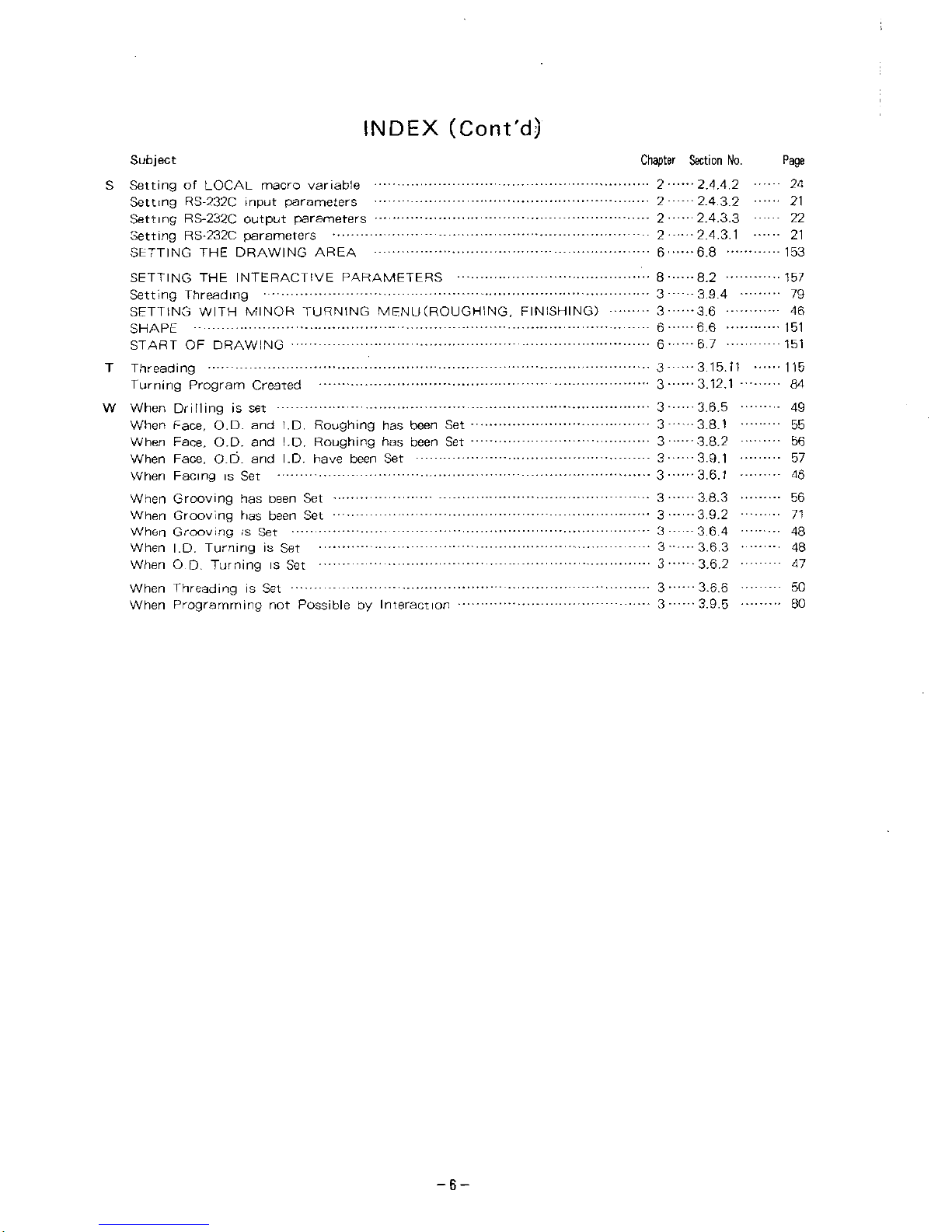
SETTING
THE
INTERACTIVE
PARAMETERS
Setting
Threading
SETTING
WITH
MINOR
TURNING
MENU
(ROUGHING.
FINISHING)
SHAPE
START
OF
DRAWING
T
Threading
Turning
Program
Created
W
When
Drilling
is
set
When
Face,
O.D.
and
I.D.
Roughing
has
been
Set
When
Face,
O.D.
and
I.D.
Roughing
has
been
Set
When
Face,
O.D.
and
I.D.
have
been
Set
When
Facing
is
Set
When
Grooving
has
been
Set
When
Grooving
has
been
Set
When
Grooving
is
Set
When
I.D.
Turning
is
Set
When
O.D.
Turning
is
Set
When
Threading
is
Set
When
Programming
not
Possible
by
Interaction
79
46
151
151
3
......
3.15.11
3
......
3.12.1
115
84
3
......
3.6.5
3
......
3.8.1
3
......
3.8.2
3
......
3.9.1
3
......
3.6.1
49
55
56
57
46
3
......
3.8.3
3
......
3.9.2
3
......
3.6.4
3
......
3.6.3
3
......
3.6.2
56
71
48
48
47
3
......
3.6.6
3
......
3.9.5
50
80
-6-
Page 7
1.
FUNCTION
OUTLINES
AND
FEATURES
The
compact
interactive
function
has
been'
designed
to
.
enable
NC
machining
part
programs
to
be
automatically
generated
through
simple
interactive
opera¬
tions
conducted
in
accordance
with
the
displayed
process
menu
on
the
CRT.
Since
the
generated
programs
mainly
use
"canned
cycles
G70
through
G76",
they
are
short,
and
process
comments
are
also
automatically
attached
to
them.
For
this
reason,
the
generated
programs
are
easy
to
understand
and
easy
to
modify
.
This
interactive
automatic
programming
function
allows
the
utilization
of
almost
all
types
of
turning
operations
including
end
facing,
O.D.
turning,
l.D.
turning,
grooving,
drilling,
and
threading,
despite
its
easy
operation.
(1)
"Compact
interactive"
automatic
programming
can
be
executed
even
while
the
NC
is
engaged
in
turning
operations.
(2)
When
finished
state
data
is
input,
the
finished
work
piece
shape
is
auto¬
matically
displayed
on
the
CRT
for
visual
check
convenience.
(3)
Because
the
automatically
generated
programs
mainly
consist
of
canned
cycles,
they
occupy
only
small
part
program
memory
capacity,
allowing
easy
modifications
and
changes.
(4)
Where
canned
cycles
are
undesirable
(for
rough
surface
removing,
etc.)
or
short
cycle
time
is
important,
turning
menus
for
free
shapes
is
available.
(5)
During
the
interactive
mode
program
generation,
any
programs
can
be
manually
added
or
change.
(6)
The
generated
programs
tion".
can
be
checked
by
means
of
the
"Drawing
func-
During
the
drawing
process,
the
material
shape
is
also
displayed.
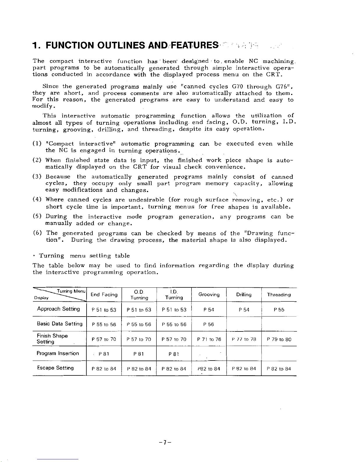
•
Turning
menu
setting
table
The
table
below
may
be
used
to
find
information
regarding
the
display
during
the
interactive
programming
operation.
Turning
Menu
O.D
Turning
l.D.
Grooving
End
Facing
Threading
Drilling
Turning
Display
Approach
Setting
P
51
to
53
P
51
to
53
P
51
to
53
P
54
P
54
P
55
Basic
Data
Setting
P
55
to
56
P
56
P
55
to
56
P
55
to
56
Finish
Shape
Setting
P
71
to
76
P
57
to
70
P
57
to
70
P
77
to
78
P
79
to
80
P
57
to
70
Program
Insertion
P
81
P
81
P
81
Escape
Setting
P
82
to
84
P
82to84
P
82
to
84
P
82to84
P
82
to
84
P82to84
-7-
Page 8

2.
NC
OPERATOR
PANEL
AND
DISPLAY
2.
1
NC
OPERATOR
PANEL
FUNCTION
OUTLINES
The
operator
panel
of
YASNAC
LX3
incorporating
the
compact
interactive
func¬
tion
is
shown
in
Fig.
2.1.
follows:
The
names
and
functions
of
the
elements
are
as
®
PAGE
KEYS
©
MEMORY
DATA
KEYS
(D
NEXT
KEY
<D
9
INCH
CRT
GRAPHIC
DISPLAY
©
EDITING
KEYS
<D
FUNCTION
KEYS
©
POWER
ON-OFF
BUTTON
©
RESET
KEY
±_
©
YASNAC
©
FUNCTION
MEM
DATA
[NEXT
|
|
POWER"!
|RESET|
|ALM|[PGN||PRM|["SET|
|
OUT
1
1
VER||
IN
[
I
ON
EDIT
|COM[|PROO|ÿPOSJ|OF5[
|lMSRT||ALTEj—
PAGE
B
DATA
ADDRESS
000
000
000
000000
000
0000
o
OFF
|CAN|
HI
WR
|
[ORG]
3
0101
01
B
3
B
©
®
o-
0
©
DATA
KEYS
©ORIGIN
KEY
©
SOFTWARE
FUNCTION
KEYS
®
CURSOR
KEYS
©
ADDRESS
KEYS
Fig.
2.
1
YASNAC
LX3
Operator
Panel
©
Power
ON-OFF
Button
(1)
POWER
ON
button
The
button
for
turning
on
Power
to
the
NC
unit.
Pushing
it
once
energizes
the
control
circuit
only,
and
pushing
it
once
more
energizes
also
the
servo
power
system.
This
button
is
also
pushed
after
an
emergency
stop,
etc.
to
re-energize
the
servo
power
system.
(2)
POWER
OFF
button
The
button
for
turning
off
power
to
the
NC
unit.
Depressing
this
button
de-energizes
both
the
control
circuit
and
the
servo
power
system
of
the
NC
unit.
-8-
Page 9
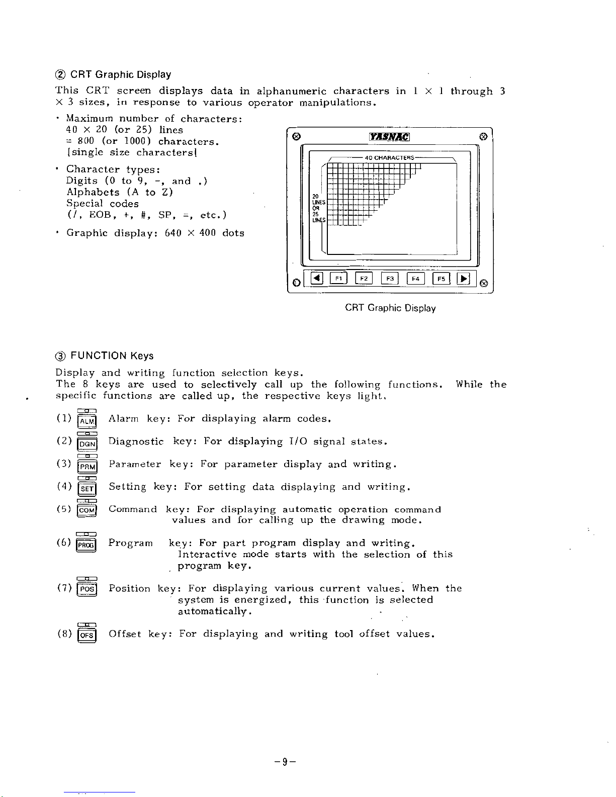
(2)
CRT
Graphic
Display
This
CRT
screen
displays
data
in
alphanumeric
characters
in
1
X
1
through
3
X
3
sizes,
in
response
to
various
operator
manipulations.
•
Maximum
number
of
characters:
40
X
20
(or
25)
lines
=
800
(or
1000)
characters.
(single
size
characters]
•
Character
types:
Digits
(0
to
9,
and
.)
Alphabets
(A
to
Z)
Special
codes
(/,
EOB,
+
,
#,
SP,
=
,
etc.)
•
Graphic
display:
640
X
400
dots
0
©
YASNAC\
40
CHAHACTEHS-
T
20
LINES
Ofl
25
LINES
©
CRT
Graphic
Display
(D
FUNCTION
Keys
Display
and
writing
function
selection
keys.
The
8
keys
are
used
to
selectively
call
up
the
following
functions.
specific
functions
are
called
up,
the
respective
keys
light.
While
the
(
1)
|ALM|
(2)
m
(3)
m
cznzp
(4)
(23
(5)
[COM)
Alarm
key:
For
displaying
alarm
codes.
Diagnostic
key:
For
displaying
I/O
signal
states.
Parameter
key:
For
parameter
display
and
writing.
Setting
key:
For
setting
data
displaying
and
writing.
Command
key:
For
displaying
automatic
operation
command
values
and
for
calling
up
the
drawing
mode.
(8)
|
PRQG
j
Program
key:
For
part
program
display
and
writing.
Interactive
mode
starts
with
the
selection
of
this
program
key.
(7)
[POS|
Position
key:
For
displaying
various
current
values.
When
the
system
is
energized,
this
function
is
selected
automatically.
(8)
|QFS|
Offset
key:
For
displaying
and
writing
tool
offset
values.
-9-
Page 10
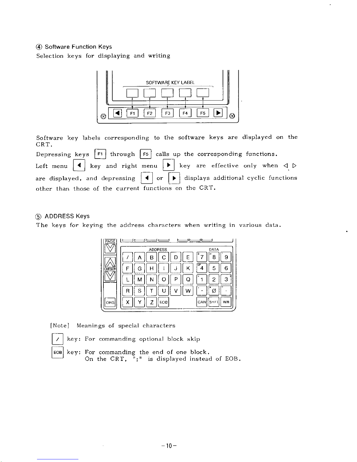
(4)
Software
Function
Keys
Selection
keys
for
displaying
and
writing
SOFTWARE
KEY
LABEL
F4~]
|F5|
[ÿ)
0
CD
CS
F3
Software
key
labels
corresponding
to
the
software
keys
are
displayed
on
the
CRT.
Depressing
keys
|
F1
j
through
|F5|
calls
up
the
corresponding
functions.
key
are
effective
only
when
<
[>
0
0
Left
menu
key
and
right
menu
S
°r
H
displays
additional
cyclic
functions
are
displayed,
and
depressing
other
than
those
of
the
current
functions
on
the
CRT.
(D
ADDRESS
Keys
The
keys
for
keying
the
address
characters
when
writing
in
various
data.
PAGE
ADDRESS
DATA
000000
000
000000
000
000000
000
000000
000
0000
CURSOR
[CAN]
jsKIFl]
|WR|
|QHG|
[Note]
Meanings
of
special
characters
key:
For
commanding
optional
block
skip
/
key:
For
commanding
the
end
of
one
block.
On
the
CRT,
"
;
"
is
displayed
instead
of
EOB.
EOB
-10-
Page 11
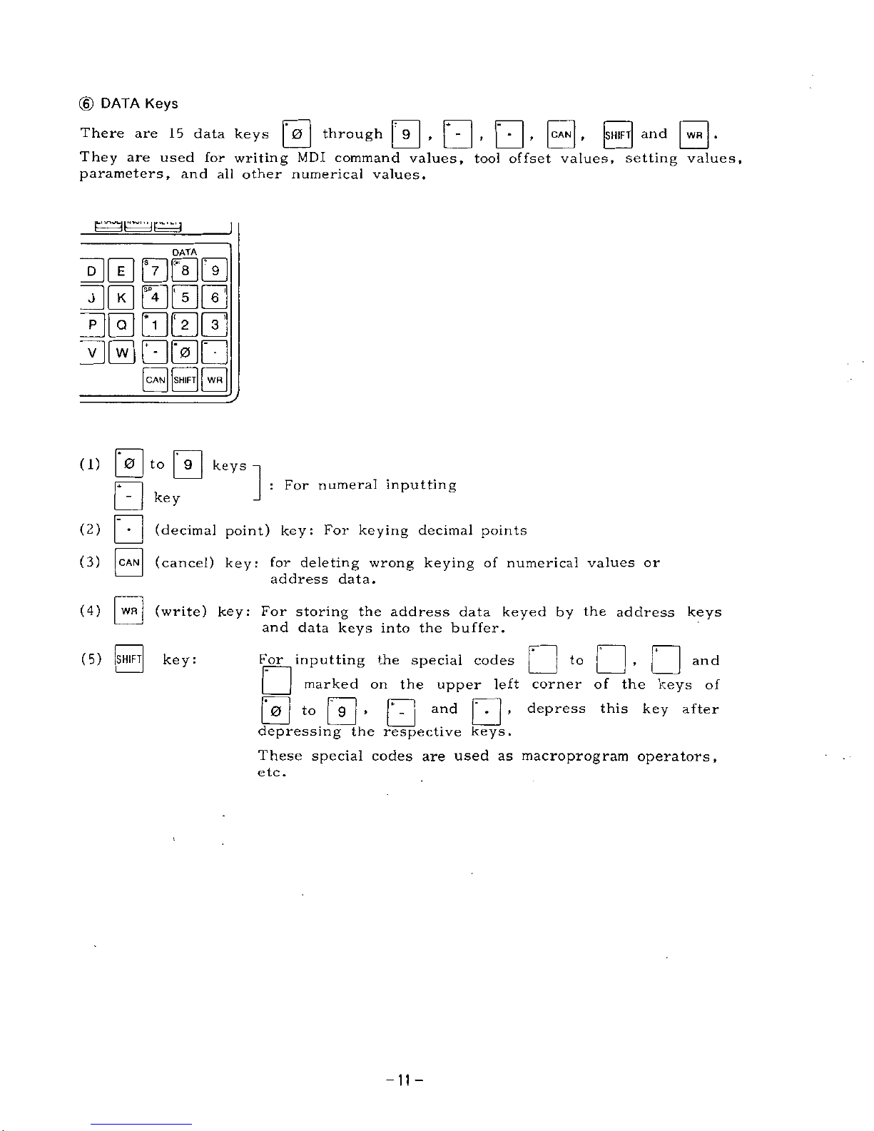
©
DATA
Keys
|0|
through
|
9
|
,
[
-
|
,
|-|
,
|CAN[
,
|SH1FT|
0-
There
are
15
data
keys
They
are
used
for
writing
MDI
command
values,
tool
offset
values,
setting
values,
parameters,
and
all
other
numerical
values.
and
DATA
30
BBS
30000
B0000
B0B0B
|CAN||SHIFT||
WR
|
|
9
|
keys
(1)
0
to
:
For
numeral
inputting
key
(2)
(decimal
point)
key:
For
keying
decimal
points
(cancel)
key:
for
deleting
wrong
keying
of
numerical
values
or
address
data.
(3)
CAN
|
WR
|
(write)
key:
For
storing
the
address
data
keyed
by
the
address
keys
and
data
keys
into
the
buffer.
(4)
|SHIFT|
key:
•
(5)
For
inputting
the
special
codes
~
|
marked
on
the
upper
left
corner
of
the
keys
of
depress
this
key
after
and
to
3
*ÿ>
0-
depressing
the
respective
keys.
These
special
codes
are
used
as
macroprogram
operators,
etc.
and
-11-
Page 12
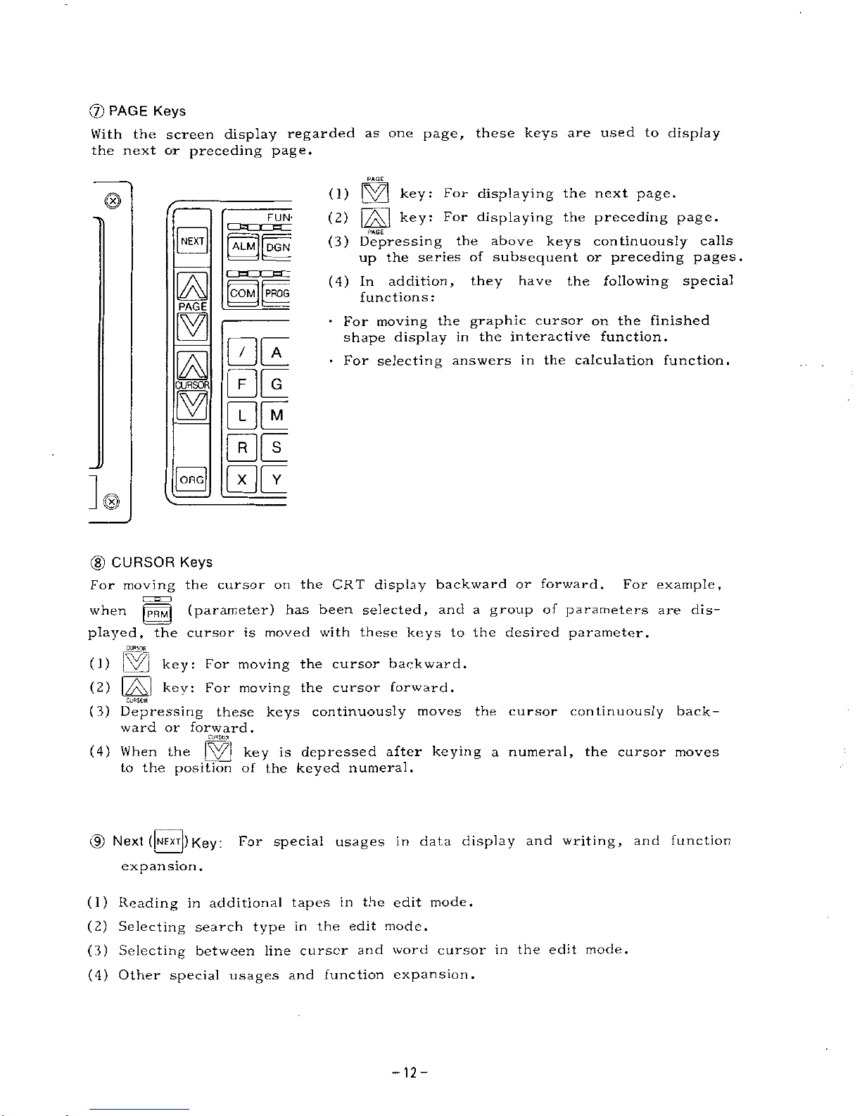
(7)
PAGE
Keys
With
the
screen
display
regarded
as
one
page,
these
keys
are
used
to
display
the
next
or
preceding
page.
PAGE
(1)
key:
For
displaying
the
next
page.
(2)
|/ÿ\j
key:
For
displaying
the
preceding
page.
PAGE
(3)
Depressing
the
above
keys
continuously
calls
up
the
series
of
subsequent
or
preceding
pages.
(4)
In
addition,
they
have
the
following
special
functions:
•
For
moving
the
graphic
cursor
on
the
finished
shape
display
in
the
interactive
function.
For
selecting
answers
in
the
calculation
function.
FUN'
NEXT
ALM
DGN
COM
PROG
PAGE
BE
F
G
CURSOR
BE
|ORG|
(8)
CURSOR
Keys
For
moving
the
cursor
on
the
CRT
display
backward
or
forward.
has
been
selected
For
example,
and
a
group
of
parameters
are
dis¬
played,
the
cursor
is
moved
with
these
keys
to
the
desired
parameter.
jp||ij
(parameter)
when
Cl/PSOP
(1)
iVl
key:
For
moving
the
cursor
backward.
(2)
|/A\|
key:
For
moving
the
cursor
forward.
CURSOR
(3)
Depressing
these
keys
continuously
moves
the
cursor
continuously
back¬
ward
or
forward.
CURSOR
(4)
When
the
[\yÿ[
key
is
depressed
after
keying
a
numeral,
the
cursor
moves
to
the
position
of
the
keyed
numeral.
(9)
Next
(|NEXT[)
Key:
For
special
usages
in
data
display
and
writing,
and
function
expansion.
(1)
Reading
in
additional
tapes
in
the
edit
mode.
(2)
Selecting
search
type
in
the
edit
mode.
(3)
Selecting
between
line
cursor
and
word
cursor
in
the
edit
mode.
(4)
Other
special
usages
and
function
expansion.
-12-
Page 13
(J§>
Origin
(|ORG[)
Key
For
setting
the
current
tool
position
as
the
origin
of
the
new
coordinate
system.
This
setting
can
be
made
for
each
axis
independently.
(1)
For
resetting
the
current
values
such
as
external.
(2)
For
resetting
the
cumulative
operation
time.
(3)
For
clearing
the
input
data
in
the
interactive
or
calculation
mode.
(4)
For
clearing
the
selected
buffer
of
the
copy
or
move
function.
(Q)
Memory
Data
Keys
and
|~
IN
j
keys
are
effective
only
in
the
edit
mode.
However,
when
inputting
and
outputting
interactive
data
in
the
interactive
I/O
display,
other
modes
are
ineffective.
(1)
[ourj
key:
For
starting
outputting
data
in
the
memory
to
the
outside
via
the
data
I/O
interface.
(2)
[
IN
j
key:
For
starting
storing
various
data
via
the
tape
reader
or
the
data
I/O
interface.
(3)
|
VER|
(verify)
key:
For
starting
the
collation
of
the
data
in
the
memory
against
the
punched
tape
data
or
data
input
through
data
I/O
interface.
four)
,
|VER|
The
for
starting
various
tape
operations.
They
are
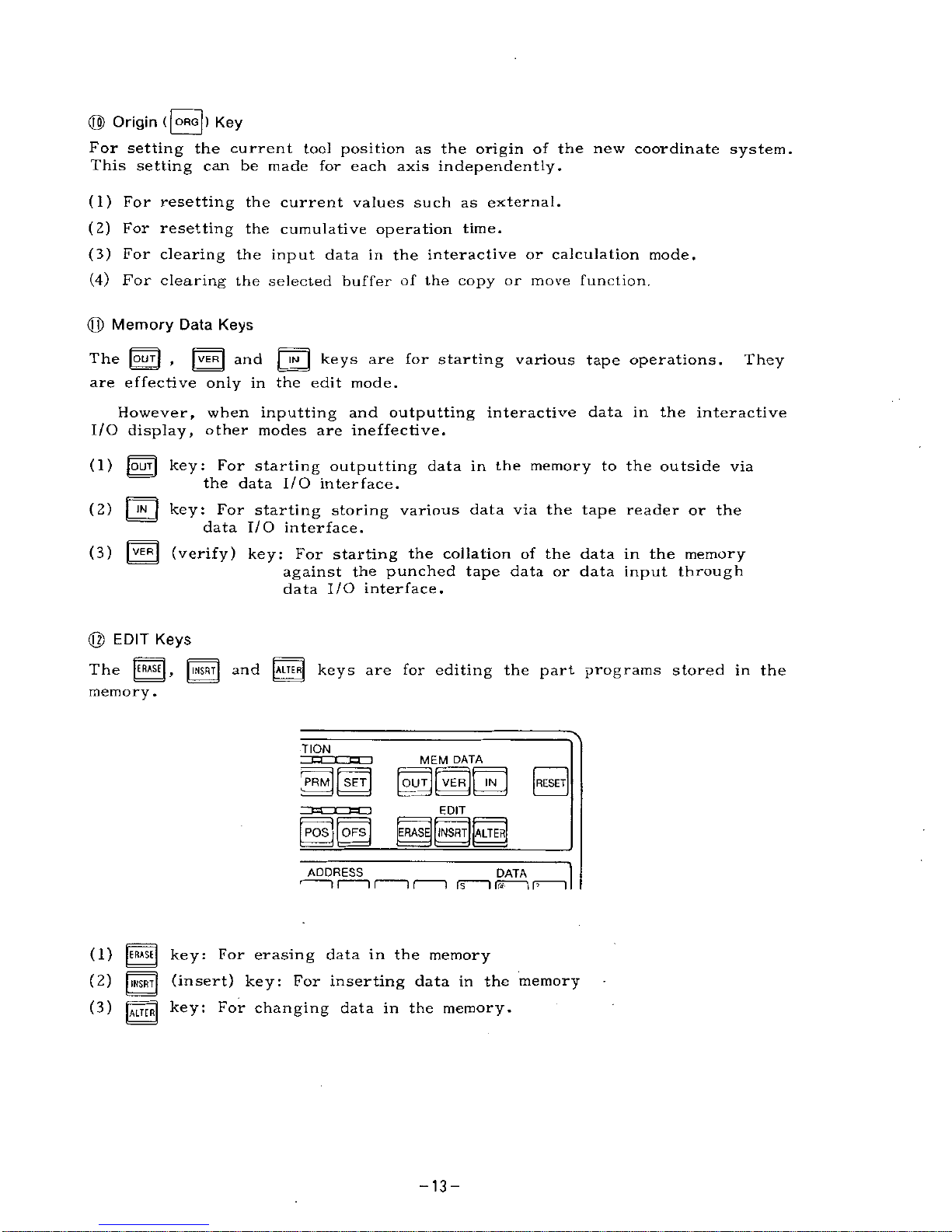
@
EDIT
Keys
[ERASE
|
r
|
INSRT|
[ALTER!
keys
are
for
editing
the
part
programs
stored
in
the
The
and
memory
.
TION
MEM
DATA
'PRM||
SET]
|
OUTJ
[VER]
[
IN
|
[RESET]
EDIT
[
POS
j
|
OFS|
|ERASE[[INSRT|[ALTER[
ADDRESS
DATA
is
"i
ns
i
r>
i
T
r
(1)
[ERASE
|
key:
For
erasing
data
in
the
memory
(2)
|
IMSRT|
(insert)
key:
For
inserting
data
in
the
memory
|MT[R|
key:
For
changing
data
in
the
memory.
(3)
-13-
Page 14
©
RESET
Key
For
resetting
the
internal
conditions
of
the
NC
(1)
Depressing
the
|RESET|
key
executes
the
following
•
Memory
rewind
•
RST
signal
sending
*
G
code
reset
•
Key
buffer
clear
*
Edit
program
on
edit
display
storing
in
memory
•
Move
command
cancel
•
Buffer
clear
•
Alarm
clearing
if
fault
has
been
cleared
•
Tool
offset
cancel
•
Aux
.
function
cancel
•
Label
skip
function
on
(2)
However,
the
following
are
not
reset
with
this
key.
•
S
and
T
commands
•
Tool
offset
values
setting
data
and
parameter
data
•
Each
axis
current
value
•
F
commands
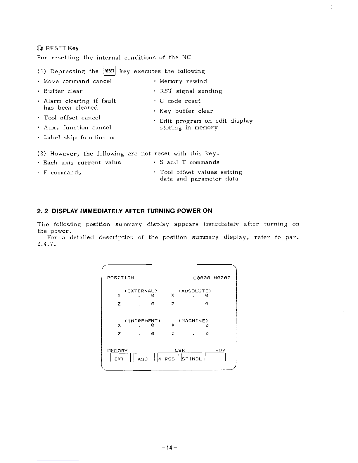
2.
2
DISPLAY
IMMEDIATELY
AFTER
TURNING
POWER
ON
The
following
position
summary
display
appears
immediately
after
turning
on
the
power.
For
a
detailed
description
of
the
position
summary
display,
refer
to
par.
2.4.7.
POSITION
Q0BO0
N0000
(
EXTERNAL)
(
ABSOLUTE)
X
X
0
0
0
0
z
z
(MACHINE)
C
INCREMENT)
0
0
X
X
z
0
0
z
RDY
MEMORY
LSK
!
SPIND
ABS
d-POS
EXT
-14-
Page 15
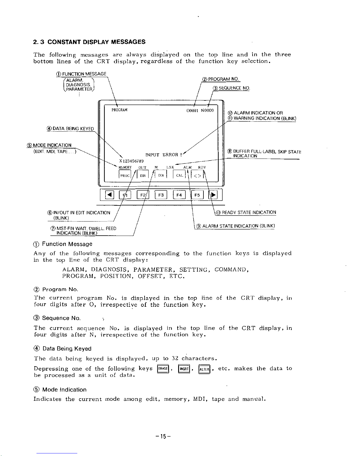
2.
3
CONSTANT
DISPLAY
MESSAGES
The
following
messages
are
always
displayed
on
the
top
line
and
in
the
three
bottom
lines
of
the
CRT
display,
regardless
of
the
function
key
selection.
(D
FUNCTION
MESSAGE
(2)
PROGRAM
NO.
'ALARM,
DIAGNOSIS,
PARAMETER,
(p
SEQUENCE
NO.
PROGRAM
00001
NOOOO
@
ALARM
INDICATION
OR
<Q)
WARNING
INDICATION
(BLINK)
©
DATA
BEING
KEYED
(5)
MODE
INDICATION
©
BUFFER
FULL
LABEL
SKIP
STATE
INDICATION
(EDIT,
MDI,
TAPE
.
. .
)
INPUT
ERROR
!
X
123456789
MhMORY
OUT
Ml
|
PROG
|
/|
DIR
|
f\
DIA
|
l.S
K
ALM
RDY
CAL
<>
5
0
B
E
a
M
READY
STATE
INDICATION
©
IN/OUT
IN
EDIT
INDICATION
(BLINK)
®
ALARM
STATE
INDICATION
(BLINK)
®
MST-FIN
WAIT,
DWELL,
FEED
INDICATION
(BLINK)
_
(f)
Function
Message
Any
of
the
following
messages
corresponding
to
the
function
keys
is
displayed
in
the
top
line
of
the
CRT
display:
ALARM,
DIAGNOSIS,
PARAMETER,
SETTING,
COMMAND,
PROGRAM,
POSITION,
OFFSET,
ETC.
(2)
Program
No.
The
current
program
No.
is
displayed
in
the
top
line
of
the
CRT
display,
in
four
digits
after
O,
irrespective
of
the
function
key.
(3)
Sequence
No.
The
current
sequence
No.
is
displayed
in
the
top
line
of
the
CRT
display,
in
four
digits
after
N,
irrespective
of
the
function
key.
@
Data
Being
Keyed
The
data
being
keyed
is
displayed,
up
to
32
characters.
Depressing
one
of
the
following
keys
[ERASE
[
,
|INSRT|
,
[ALTE
R|
»
etc.
makes
the
data
to
be
processed
as
a
unit
of
data.
(D
Mode
Indication
Indicates
the
current
mode
among
edit,
memory,
MDI,
tape
and
manual.
-15-
Page 16
(6)
IN/OUT
in
Edition
Indication
(Blink)
While
punched
tape
data
is
under
input,
output
or
edit,
the
following
messages
are
displayed
by
blinking.
Tape
under
reading
Tape
under
collation
Tape
under
output
Data
under
change
in
edit
mode
Data
under
insertion
in
edit
mode
Data
under
erasure
in
edit
mode
"IN"
"VER"
"OUT"
"ALT"
"INS"
"ERS"
®
MST-FIN
wait,
Dwell,
Feed
Indication
(Blinking)
M
command
FIN
waiting
S
command
FIN
waiting
T
command
FIN
waiting
During
feed,
while
rapid
feed,
"R"
is
displayed.
During
tape
reading
During
dwelling
"M"
11
S"
n
'pii
ti
pn
ii
pn
"DWELL"
M,
S,
T,
F,
and
P
are
all
displyed
independently.
(D
Buffer-Full,
Label
Skip
State
Indication
"BUF"
Displayed
when
forward
reading
is
completed.
Displayed
when
label
skip
is
on.
"LSK"
(9)
Alarm
State
Indication
(Blinking)
An
alarm
indication
continues
blinking
until
the
cause
is
eliminated
and
reset¬
ting
is
effected.
"ALM"
Alarm
state
is
ON.
Battery
alarm
is
ON.
Both
alarm
state
and
battery
alarm
are
ON.
"BAT"
"A/B"
@)
Ready
State
Indication
-IRDY"
System
is
in
order,
and
ready
for
operation.
-16-
Page 17
(Q)
Warning
Indication
(Blinking)
The
following
warnings
are
minor
errors
caused
by
keying,
searching
manipu¬
lation,
etc.,
and
not
verifiable
alarms.
When
any
of
these
warning
is
displayed,
depressing
any
key
turns
them
off.
(usually
|
CAN
|
)
When
an
alarm
and
a
warning
occur
simultaneously,
the
warning
display
has
the
priority.
"INPUT
ERROR!"
Format
error
during
data
keying.
Collation
error
with
the
|
VER|
key.
Already
part
program
with
same
No.
is
stored.
Edit
process
is
attempted
with
EDIT
LOCK.
More
than
99
(basic)
or
199
(optional)
part
programs
registration
is
attempted.
Memory
capacity
is
exceeded
in
storing
part
programs
.
Horizontal
parity
check
error
in
tape
reading.
Vertical
parity
check
error
in
tape
reading.
"ILLEGAL
CHARACTER!"
..
Code
which
cannot
be
understood
occurs
in
tape
reading
.
No
intended
code
found
through
searching.
"MACRO
INTERLOCK!"
....
Operation
of
programs
interlocked
by
08000
or
09000
level
is
attempted.
Designation
of
range
over
permissible
1024
characters
by
editor
is
attempted.
"EDIT
MEMORY
FULL
!"
..
Any
part
program
exceeding
40
m
of
meter
length
is
displayed
or
edited.
"ALREADY
IN"
"EDIT
LOCK!"
"PROGRAM
OVER!"
"MEMORY
OVER!"
"TH
PARITY
ERROR!"
"TV
PARITY
ERROR!"
"NOT
FOUND!"
"AREA
OVER!"
The
above
indications
all
blink.
©
Alarm
Indication
The
above
indications
all
blink.
When
a
NC
alarm
occurs
on
the
same
line
as
the
line
for
which
a
warning
has
been
indicated,
that
alarm
content
is
displayed
in
one
line.
However,
"alarm
310
SERVO
OFF"
is
not
displayed,
because
this
alarm
is
of
a
different
nature
from
other
NC
alarms.
When
two
or
more
alarms
occur,
only
the
top
most
one
in
the
alarm
list
is
displayed.
When
an
alarm
and
a
warning
occur
simultane¬
ously,
only
the
warning
is
displayed
with
priprity.
-17-
Page 18
2.
4
FUNCTION
DISPLAY
With
a
unit
equipped
with
the
Compact
Interactive
Function,
the
operation
and
display
for
the
FUNCTION
keys
are
partly
different
from
those
described
in
YASNAC
LX3
Manual
(TOE-C843-9.
20)
,
as
described
below:
c~nm
2.4.1
Display
with
pÿjj
FUNCTION
Key
The
operator
manipulations
for
displaying
alarm
codes
and
other
data
are
as
follows:
(1)
Depress
gD
FUNCTION
key.
One
of
the
following
is
displayed.
(a)
Alarm
No.
and
message
(b)
Operating
time
display
(c)
Maintenance
history
display
(2)
Depressing
the
page
|ÿ7|
|2ÿ|
keys
changes
the
above
displays
one
after
another.
In
addition,
depressing
the
software
keys
|
ALARM
[
,
and
|TIMER
|
directly
calls
up
(a)
(ALARM)
and
(b)
(TIMER)
displays
respectively.
(3)
For
details
of
the
above
displays,
refer
to
the
standard
YASNAC
LX3
Manual.
(a)
(ALARM)
..........
4.
3.9.1
Alarm
No.
display
4.
3.
9.
2
Message
display
(b)
(TIMER)
...........
4.
3.
9.
4
Operating
time
display
(c)
(MAINTENANCE)
...4.
3.
9.
5
Maintenance
history
display
-18-
Page 19
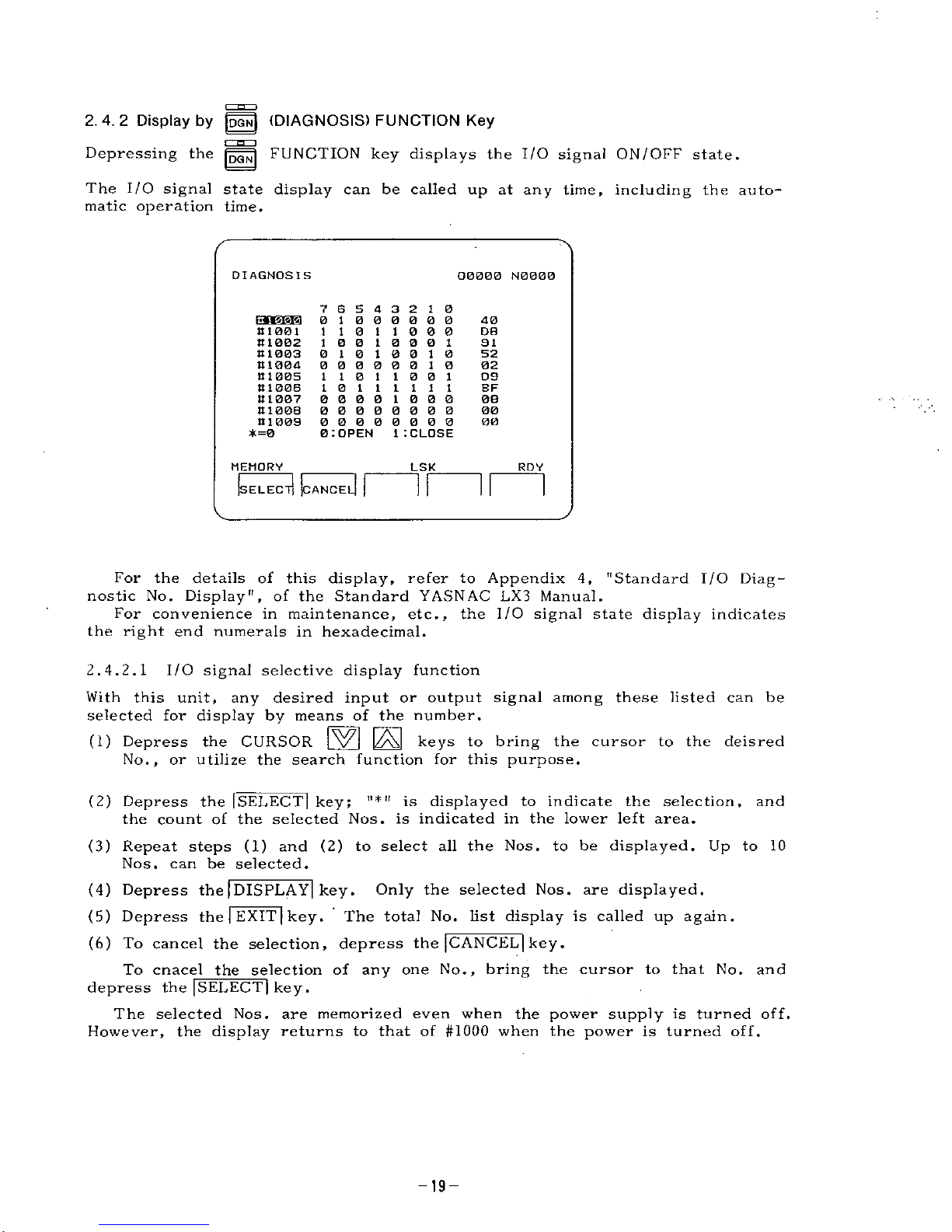
2.4.2
Display
by
||N|
(DIAGNOSIS)
FUNCTION
Key
Depressing
the
FUNCTION
key
displays
the
I/O
signal
ON/OFF
state.
The
I/O
signal
state
display
can
be
called
up
at
any
time,
including
the
auto¬
matic
operation
time.
DIAGNOSIS
O000B
N0000
7
6
5
4
3
2
1
0
01
000000
110
110
0 0
1
0 0
1
0
0
0
1
0
10
10
0
10
00000010
110
110
0
1
10
111111
0000
1
000
00000000
00000000
0
:
OPEN
40
81001
111002
It
1
003
111004
81005
81006
81007
81006
81009
*=0
D8
91
52
02
09
BF
08
00
00
1
I
CLOSE
MEMORY
LSK
RDY
(SELECT]
(
dl
]
CANCE
For
the
details
of
this
display,
refer
to
Appendix
4,
"Standard
I/O
Diag¬
nostic
No.
Display",
of
the
Standard
YASNAC
LX3
Manual.
For
convenience
in
maintenance,
etc.,
the
I/O
signal
state
display
indicates
the
right
end
numerals
in
hexadecimal.
2.4.2.1
I/O
signal
selective
display
function
With
this
unit,
any
desired
input
or
output
signal
among
these
listed
can
be
selected
for
display
by
means
of
the
number.
(1)
Depress
the
CURSOR
(zAJ
keys
to
bring
the
cursor
to
the
deisred
No.,
or
utilize
the
search
function
for
this
purpose.
(2)
Depress
the
|SELECT|
key;
ii
*
it
is
displayed
to
indicate
the
selection,
and
the
count
of
the
selected
Nos.
is
indicated
in
the
lower
left
area.
(3)
Repeat
steps
(1)
and
(2)
to
select
all
the
Nos.
to
be
displayed.
Up
to
10
Nos.
can
be
selected.
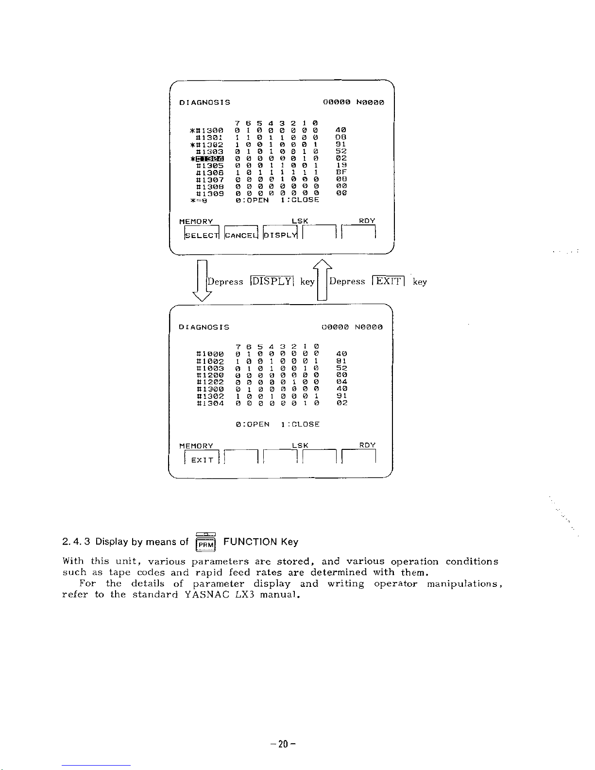
(4)
Depress
the
|
DISPLAY|
key.
Only
the
selected
Nos.
are
displayed.
(5)
Depress
the
|
EXIT
|
key.
The
total
No.
list
display
is
called
up
again.
(6)
To
cancel
the
selection,
depress
the
[CANCEL]
key
.
To
cnacel
the
selection
of
any
one
No.,
bring
the
cursor
to
that
No.
and
depress
the
|SELECT|
key.
The
selected
Nos.
are
memorized
even
when
the
power
supply
is
turned
off.
However,
the
display
returns
to
that
of
#1000
when
the
power
is
turned
off.
-19-
Page 20
O0000
N0000
DIAGNOSIS
7
6
5
4
3
2
1
0
0
1
000000
110
110
0
0
10010001
01010010
00000010
0
0 0
1
1
0
0
1
10
111111
0000
1000
00000000
00000000
0
:OPEN
40
*tt
1
300
4
1301
*111302
111303
DB
9
I
52
*p«»cisri
02
19
11
1305
111306
It
1307
8
1308
8
1309
*=8
BF
00
00
00
1
.'CLOSE
RDY
LSK
MEMORY
v|
I
d
d
Is
DISPL
CANCE
ELEC
Depress
|DISPLY|
key
Depress
|
EXIT
|
key
\7
O0000
N0000
DIAGNOSIS
7
6
5
4
3
2
10
01000000
1
0
0
1
0
0
0
1
0
10
10
0
10
00000000
00000
1
00
01
000000
1
0
0
1
0
0
0
1
0
0
0
0 0
0
10
40
81000
81002
8
1003
81200
8
1202
81300
81302
81304
91
52
00
04
40
91
02
0
:OPEN
1
ICLOSE
RDY
LSK
MEMORY
ir
EXIT
2.4.3
Display
by
means
of
FUNCTION
Key
With
this
unit,
various
parameters
are
stored,
and
various
operation
conditions
such
as
tape
codes
and
rapid
feed
rates
are
determined
with
them.
For
the
details
of
parameter
display
and
writing
operator
manipulations,
refer
to
the
standard
YASNAC
LX3
manual.
-20-
Page 21
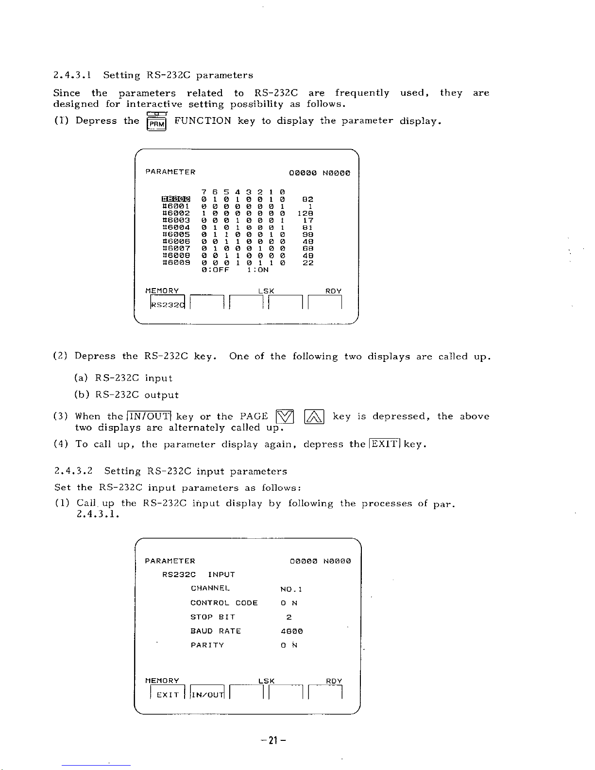
2.
4.
3.1
Setting
RS-232C
parameters
Since
the
parameters
related
to
RS-232C
are
frequently
used,
they
are
designed
for
interactive
setting
possibility
as
follows.
(1)
Depress
the
jpRM|
FUNCTION
key
to
display
the
parameter
display.
PARAMETER
00000
N0000
7
6
5
4
3
2
1
0
0
10
10
0
10
0 0 0 000 0
1
1
0000000
0 0
010
0
0
1
0
1
0
1
0 0
0
1
0
1
1
0 0
0
1
0
001
10000
01000100
001
10000
00010
1
1
0
0
:
OFF
B2
t-iil'WA
46001
46002
46003
46004
46005
46006
46007
46008
46009
1
128
17
81
98
48
68
48
22
1
:
ON
MEMORY
LSK
ROY
31
If
RS232
(2)
Depress
the
RS-232C
key.
(a)
RS-232C
input
(b)
RS-232C
output
(3)
When
the
jlN/OUT|
key
or
the
PAGE
|ÿ7[
|ÿJ
key
is
depressed,
the
above
two
displays
are
alternately
called
up.
(4)
To
call
up,
the
parameter
display
again,
depress
the
|
EXIT
|
key
.
One
of
the
following
two
displays
are
called
up.
2.4.
3.2
Setting
RS-232C
input
parameters
Set
the
RS-232C
input
parameters
as
follows:
(1)
Call
up
the
RS-232C
input
display
by
following
the
processes
of
par.
2.
4.
3.1.
PARAMETER
00000
N0000
RS232C
INPUT
CHANNEL
NO
.
1
CONTROL
CODE
0
N
STOP
BIT
2
BAUD
RATE
4800
O
N
PARITY
MEMORY
LSK
RDY
EXIT
I
N/QU
-21-
Page 22
(2)
The
RS-232C
input
parameters
are
in
the
five
items
as
shown
in
the
dis¬
play
above.
(3)
Derpess
the
CURSOR
|\ÿj
keys
to
make
the
intended
items
on
the
display
blink.
(4)
Depressing
the
by
one
as
shown
below.
(a)
CHANNEL
(b)
CONTROL
CODE
(c)
STOP
BIT
(d)
BAUD
RATE
(e)
PARITY
For
setting
the
baud
rate,
digits
may
be
directly
input
with
keys
such
0
key
changes
the
setting
of
the
respective
items
one
No.
1
or
No.
2
ON
or
OFF
1
or
2
50,
100,
110,
150,
200,
300,
600,
1200,
2400,
4800,
9600
ON
or
OFF
00000.
as
(5)
Set
the
RS-232C
input
parameters
in
conformance
with
the
setting
of
the
units
to
be
connected
to
RS-232C.
(6)
Precautions
The
No.
2
channels
are
displayed
when
the
optional
second
RS-232C
is
con¬
nected.
Without
this
optional
unit,
No.
1
only
is
displayed.
Setting
RS-232C
output
parameters
Set
the
RS-232C
output
parameters
as
follows:
(1)
Call
up
the
RS-232C
output
display
by
following
the
processes
in
Par.
2.
4.
3.1.
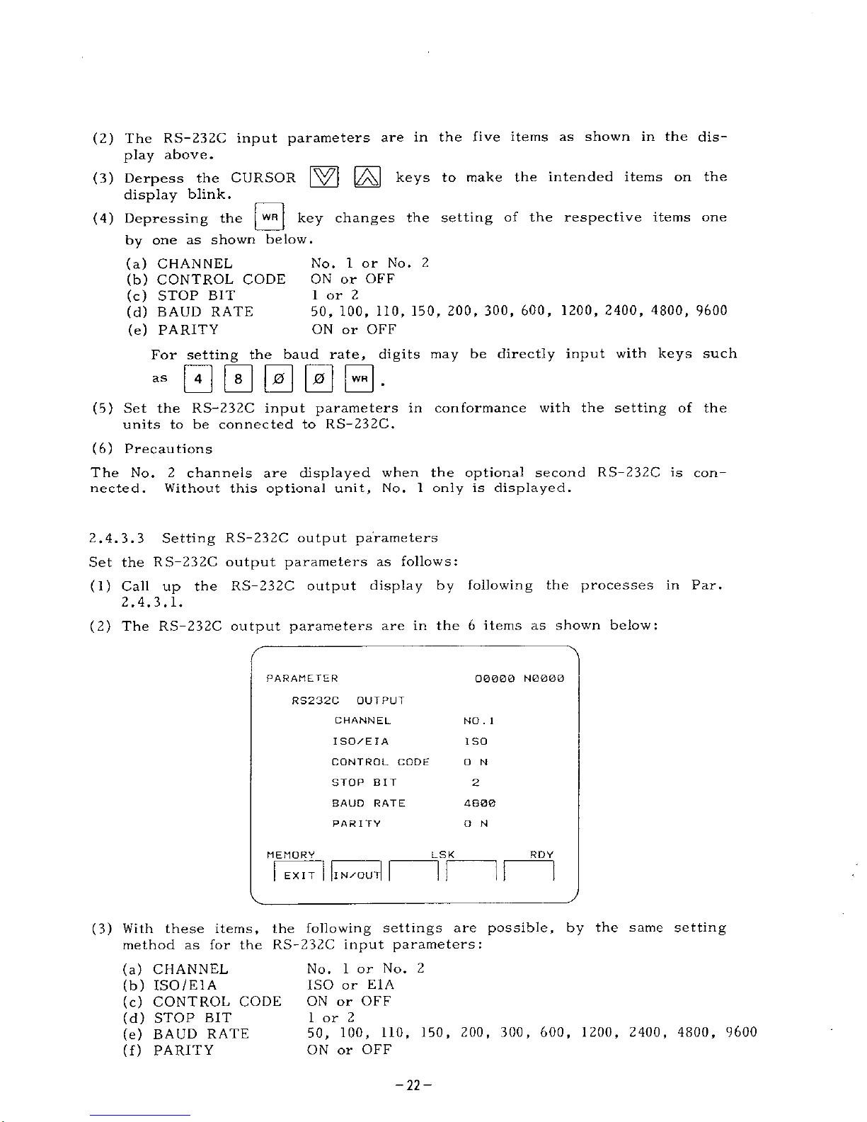
(2)
The
RS-232C
output
parameters
are
in
the6items
as
shown
below:
2.
4.
3.
3
PARAMETER
00000
N0000
RS232C
OUTPUT
CHANNEL
NO
.
1
I
SO/E
I
A
ISO
CONTROL
CODE
O
N
STOP
BIT
2
BAUD
RATE
4800
PARITY
O
N
MEMORY
LSK
RDY
HI
II
IN/OU
EXIT
(3)
With
these
items,
the
following
settings
are
possible,
by
the
same
setting
method
as
for
the
RS-232C
input
parameters:
(a)
CHANNEL
(b)
ISO
/El
A
(c)
CONTROL
CODE
(d)
STOP
BIT
(e)
BAUD
RATE
(f)
PARITY
No.
1
or
No.
2
ISO
or
E1A
ON
or
OFF
1
or
2
50,
100,
110,
150,
200,
300,
600,
1200
ON
or
OFF
2400,
4800,
9600
-22-
Page 23
(4)
Set
the
RS-232C
parameters
in
conformance
with
the
setting
of
the
unit
to
be
connected
to
RS-232C.
(5)
Cautions
*
The
set
parameters
become
effective
immediately
upon
keying
the
WR
key
or
the
digit
DATA
keys.
-
•
The
No.
2
channel
is
displayed
when
an
optional
second
RS-232C
is
connected.
Without
the
optional
RS-232C,
No.
1
channel
only
is
displayed.
L.-TX-J
2.4.4
Display
by
the
use
of
[
SET
j
FUNCTION
Key
This
unit
has
setting
data
stored
in
the
internal
memory,
and
the
stored
data
are
used
for
selectively
turning
various
functions
ON
or
OFF,
and
as
the
control
constants
for
various
functions.
For
the
details,
refer
to
Appendix
1
"Setting
No.
list"
of
the
standard
YASNAC
LX3
Manual.
r~n
i
(1)
Depressing
the
jÿTfj
FUNCTION
key
only
displays
the
setting
data.
(2)
For
details
of
the
display
and
writing
of
setting
data,
refer
to
Par.
4.3.6
of
the
standard
YASNAC
LX3
Manual
.
2.4.4.1
Setting
internal
toggle
switch
(1)
Even
when
the
9
basic
function
switches
are
eliminated
from
the
operator's
panel
of
the
machine,
the
relevant
functions
can
be
turned
ON
and
OFF
simply
by
the
setting
on
the
NC
operator's
panel.
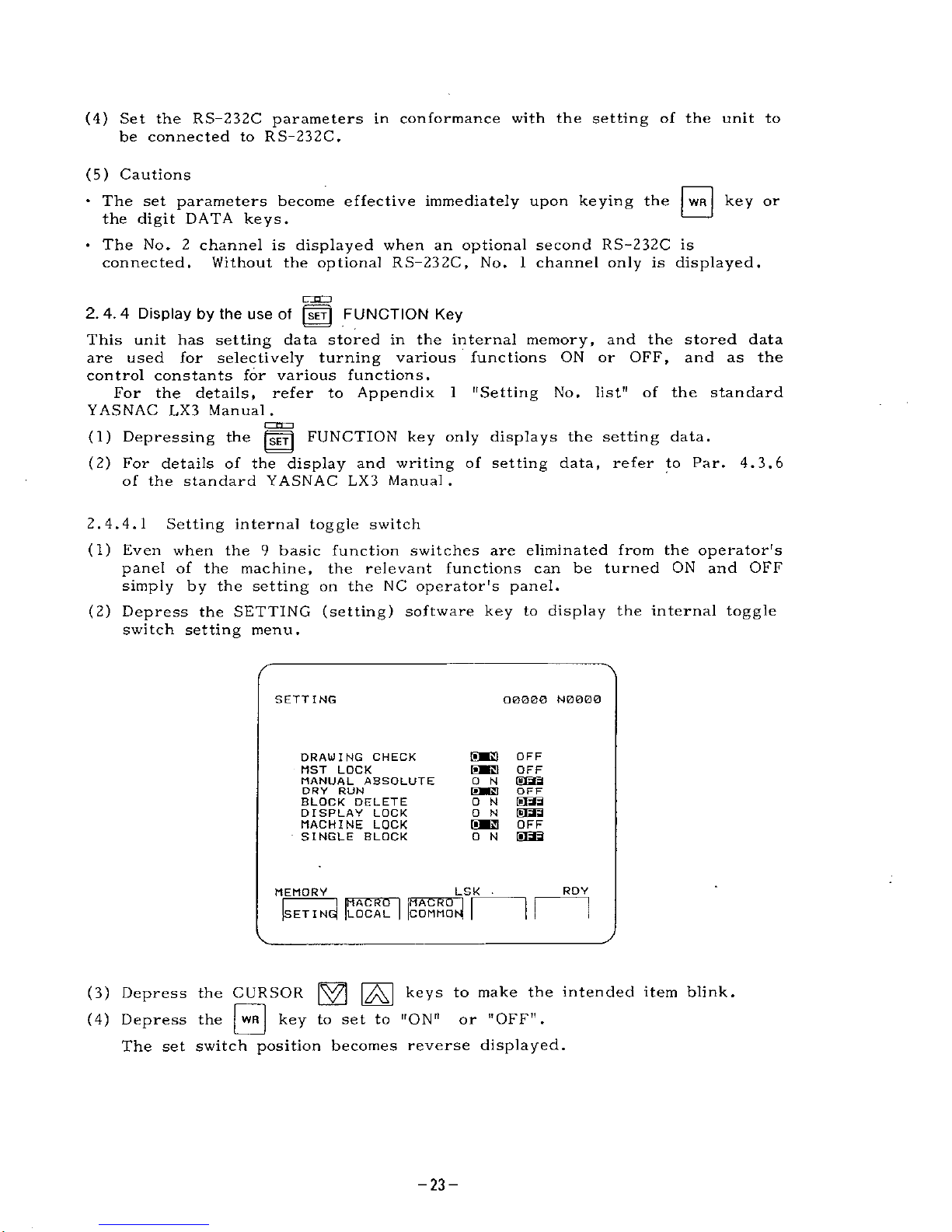
(2)
Depress
the
SETTING
(setting)
software
key
to
display
the
internal
toggle
switch
setting
menu.
SETTING
O0Q00
N0000
SK3
[iMBl
0
N
[ÿMl
O
N
ON
[ÿM3
O
N
OFF
OFF
[8iaa
OFF
EBB
OFF
1SBB
DRAUING
CHECK
MST
LOCK
MANUAL
ABSOLUTE
DRY
RUN
BLOCK
DELETE
DISPLAY
LOCK
MACHINE
LOCK
SINGLE
BLOCK
RDY
LSK
.
MEMORY
MACRO
LOCAL
3!
COMMOI
SETIN
(3)
Depress
the
CURSOR
|ÿ7]
|ÿJ
keys
(4)
Depress
the
|
WR
j
to
make
the
intended
item
blink.
key
to
set
to
"ON"
or
"OFF".
The
set
switch
position
becomes
reverse
displayed.
-23-
Page 24
(5)
When
the
"DRAWING
CHECK"
setting
is
changed,
the
settings
shown
below
are
changed
automatically.
Use
this
"DRAWING
CHECK"
setting
when
checking
the
programs
generated
through
the
interactive
function
or
manual
function
by
the
drawing
check
function.
(a)
MST
LOCK
(b)
DRY
RUN
(c)
MACHINE
LOCK
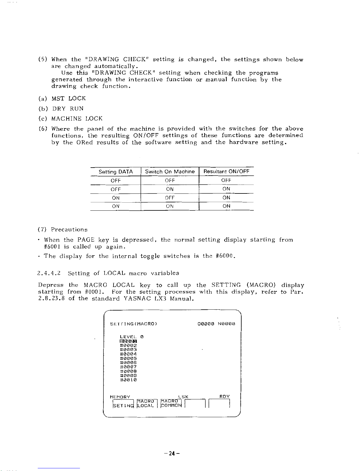
(6)
Where
the
panel
of
the
machine
is
provided
with
the
switches
for
the
above
functions,
the
resulting
ON
/OFF
settings
of
these
functions
are
determined
by
the
ORed
results
of
the
software
setting
and
the
hardware
setting.
Resultant
ON/OFF
Switch
On
Machine
Setting
DATA
OFF
OFF
OFF
ON
ON
OFF
ON
OFF
ON
ON
ON
ON
(7)
Precautions
•
When
the
PAGE
key
is
depressed,
the
normal
setting
display
starting
from
#6001
is
called
up
again.
•
The
display
for
the
internal
toggle
switches
is
the
#6000.
2.
4.4.
2
Setting
of
LOCAL
macro
variables
Depress
the
MACRO
LOCAL
key
to
call
up
the
SETTING
(MACRO)
display
starting
from
#0001.
For
the
setting
processes
with
this
display,
refer
to
Par.
2.8.23.8
of
the
standard
YASNAC
LX3
Manual.
SETT
ING(MACRO)
00000
N0000
LEVEL
0
00002
00003
00004
00005
00006
00007
00008
00008
O00
10
RDY
LSK
MEMORY
I
a
MACRO
COMMO
MACRO
LOCAL
SETIN
-24-
Page 25
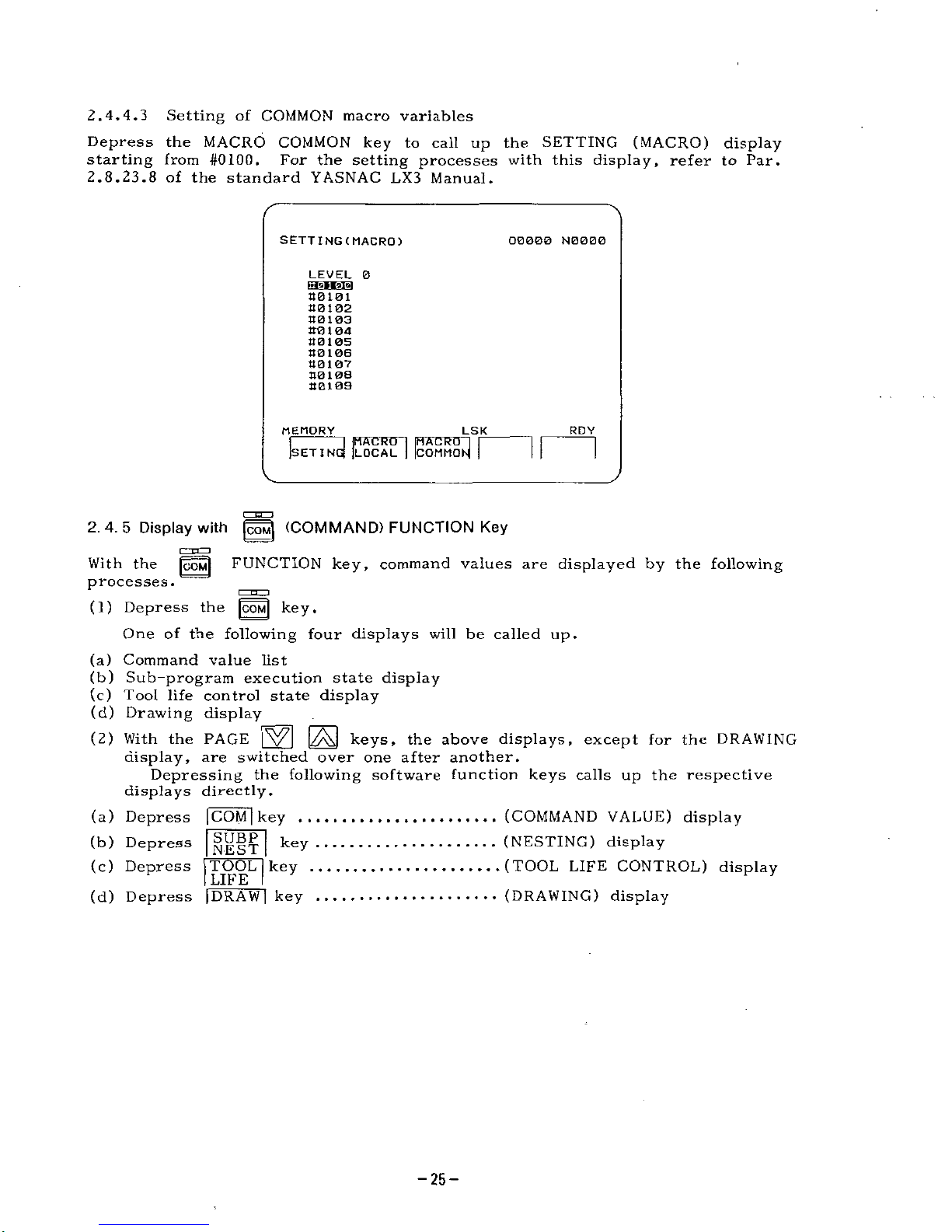
2.
4.
4.
3
Setting
of
COMMON
macro
variables
Depress
the
MACRO
COMMON
key
to
call
up
the
SETTING
(MACRO)
display
starting
from
#0100.
For
the
setting
processes
with
this
display,
refer
to
Par.
2.8.23.8
of
the
standard
YASNAC
LX3
Manual.
SETTING(MACRQ)
O0000
N0000
LEVEL
0
EHEEB
801
02
80103
80104
801
05
80106
80107
80108
80109
LSK
]
MACRO
]
|
POMMOM
]
MEMORY
RDY
MACRO
G)
[LOCAL
SET
I
N
2.
4.
5
Display
with
|U
(COMMAND)
FUNCTION
Key
c=n=
D
With
the
|COM|
FUNCTION
key,
command
values
are
displayed
by
the
following
processes.
_
p
n,..J
(1)
Depress
the
|COM|
key.
One
of
the
following
four
displays
will
be
called
up.
(a)
Command
value
list
(b)
Sub-program
execution
state
display
(c)
Tool
life
control
state
display
(d)
Drawing
display
(2)
With
the
PAGE
keys,
the
above
displays,
except
for
the
DRAWING
display,
are
switched
over
one
after
another,
Depressing
the
following
software
function
keys
calls
up
the
respective
displays
directly.
(a)
Depress
|COM
|
key
(b)
Depress
(c)
Depress
TOOL
key
LIFE
(d)
Depress
[DRAW
|
key
(COMMAND
VALUE)
display
(NESTING)
display
(TOOL
LIFE
CONTROL)
display
(DRAWING)
display
SUBP
NEST
key
-25-
Page 26
(3)
For
a
detailed
description
of
these
displays,
refer
to
the
following
sec¬
tions:
(a)
(COMMAND
VALUE)
Standard
YASNAC
LX3
Manual
Par.
4.
3.
2.1
Standard
YASNAC
LX3
Manual
Par.
4.
3.2.2
(b)
(NESTING)
(c)
(TOOL
LIFE
CONTROL)
Standard
YASNAC
LX3
Manual
Par,
4.
3.2.3
Par.
6
of
this
manual
(d)
(DRAWING)
2.
4.
6
Display
with
(PROGRAM)
FUNCTION
Key
(1)
Depress
the
|PR0G|
FUNCTION
key
to
call
up
the
PROGRAM
display.
(2)
The
program
functions
are
in
the
following
6
modes,
each
differing
in
function
and
operator
manipulation.
(a)
JOG
mode
Mode
for
manual
continuous
feeding
of
the
machine
(b)
HANDLE/STEP
mode
Mode
for
using
manual
pulse
generator
(c)
TAPE
mode
Mode
for
NC
tape
operation
(d)
MDI
mode
Mode
for
writing
command
values
with
MDI
(manual
data
input)
and
their
execution
(e)
MEMORY
mode
Mode
for
automatic
operation
of
stored
programs
(f)
EDIT
mode
Mode
for
program
storing,
reading
in
and
from
the
memory,
and
for
editing
(3)
For
the
details
of
the
above
6
modes,
refer
to
Par.
4.3.3
of
the
Standard
YASNAC
LX3
Manual.
-26-
Page 27
2.
4.
6.1
Common
mode
display
With
the
program
function,
there
are
displays
which
are
common
to
all
the
modes
.
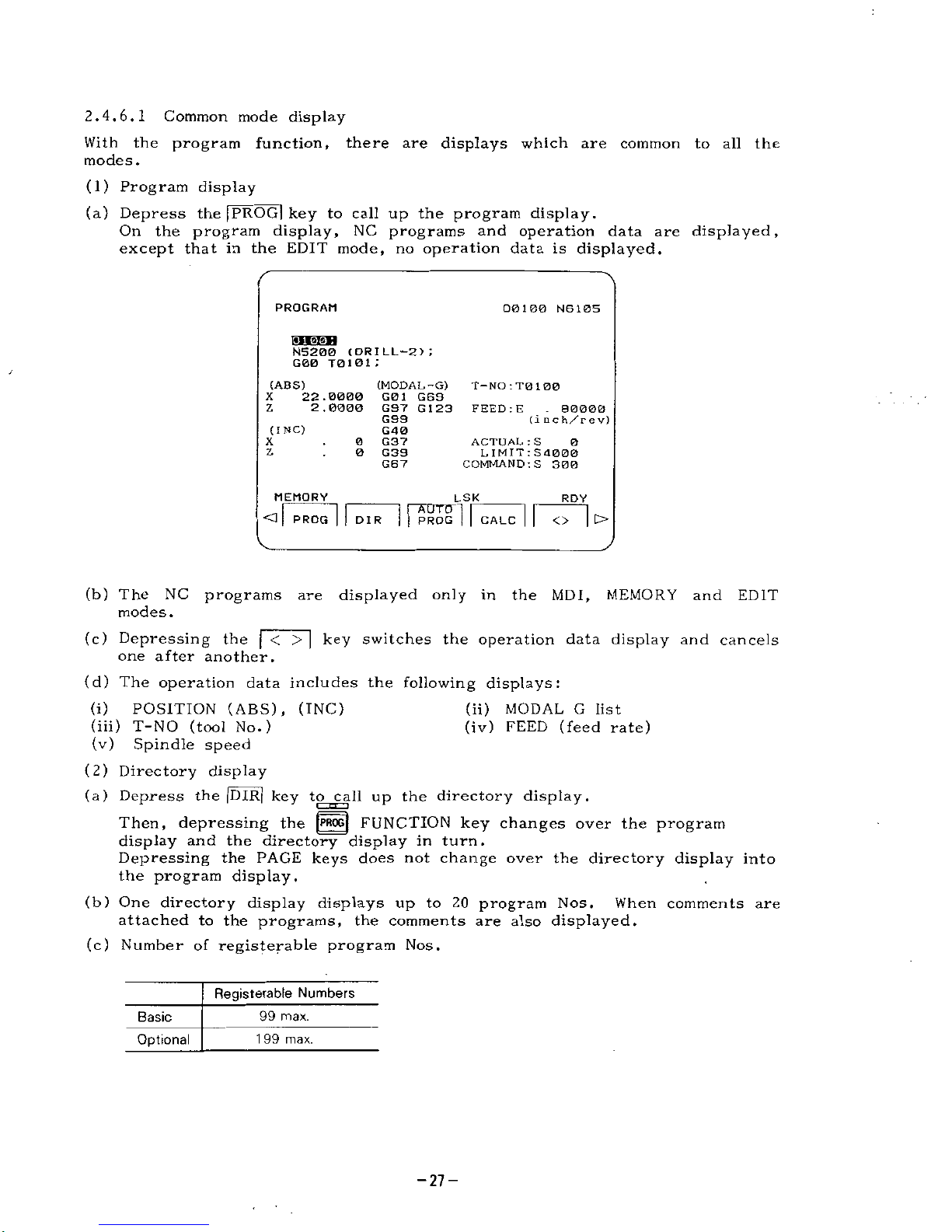
(1)
Program
display
(a)
Depress
the
|PROG|
key
to
call
up
the
program
display.
On
the
program
display,
NC
programs
and
operation
data
are
displayed,
except
that
in
the
EDIT
mode,
no
operation
data
is
displayed.
PROGRAM
00100
N6105
N5200
(DRILL-2)
;
G00
T0101
;
/
(ABS)
(MODAL
-G)
T—
NO
:
T0
1
00
22.0000
G01
G69
2.0000
G97
G
1
23
G99
G40
0
G37
0
G39
G67
X
Z
FEED
:
E
.
80000
(
i
n
c
h/r
e
v)
(INC)
X
ACTUAL
:
S
LIMIT
:
S
4
000
COMMAND
:S
300
0
Z
MEMORY
LSK
RDY
<1
<>
|
t>
PROG
DIR
PROG
CALC
(b)
The
NC
programs
are
displayed
only
in
the
MDI,
MEMORY
and
EDIT
modes.
(c)
Depressing
the
|~<
>
|
key
switches
the
operation
data
display
and
cancels
one
after
another.
(d)
The
operation
data
includes
the
following
displays:
(i)
POSITION
(ABS),
(INC)
(iii)
T-NO
(tool
No.)
(v)
Spindle
speed
(2)
Directory
display
(a)
Depress
the
|DIR|
key
to
call
up
the
directory
display.
Then,
depressing
the
|P»OG(
FUNCTION
key
changes
over
the
program
display
and
the
directory
display
in
turn.
Depressing
the
PAGE
keys
does
not
change
over
the
directory
display
into
the
program
display.
(b)
One
directory
display
displays
up
to
20
program
Nos.
When
comments
are
attached
to
the
programs,
the
comments
are
also
displayed.
(c)
Number
of
registerable
program
Nos.
(ii)
MODAL
G
list
(iv)
FEED
(feed
rate)
Registerable
Numbers
Basic
99
max.
Optional
1
99
max.
-27-
Page 28
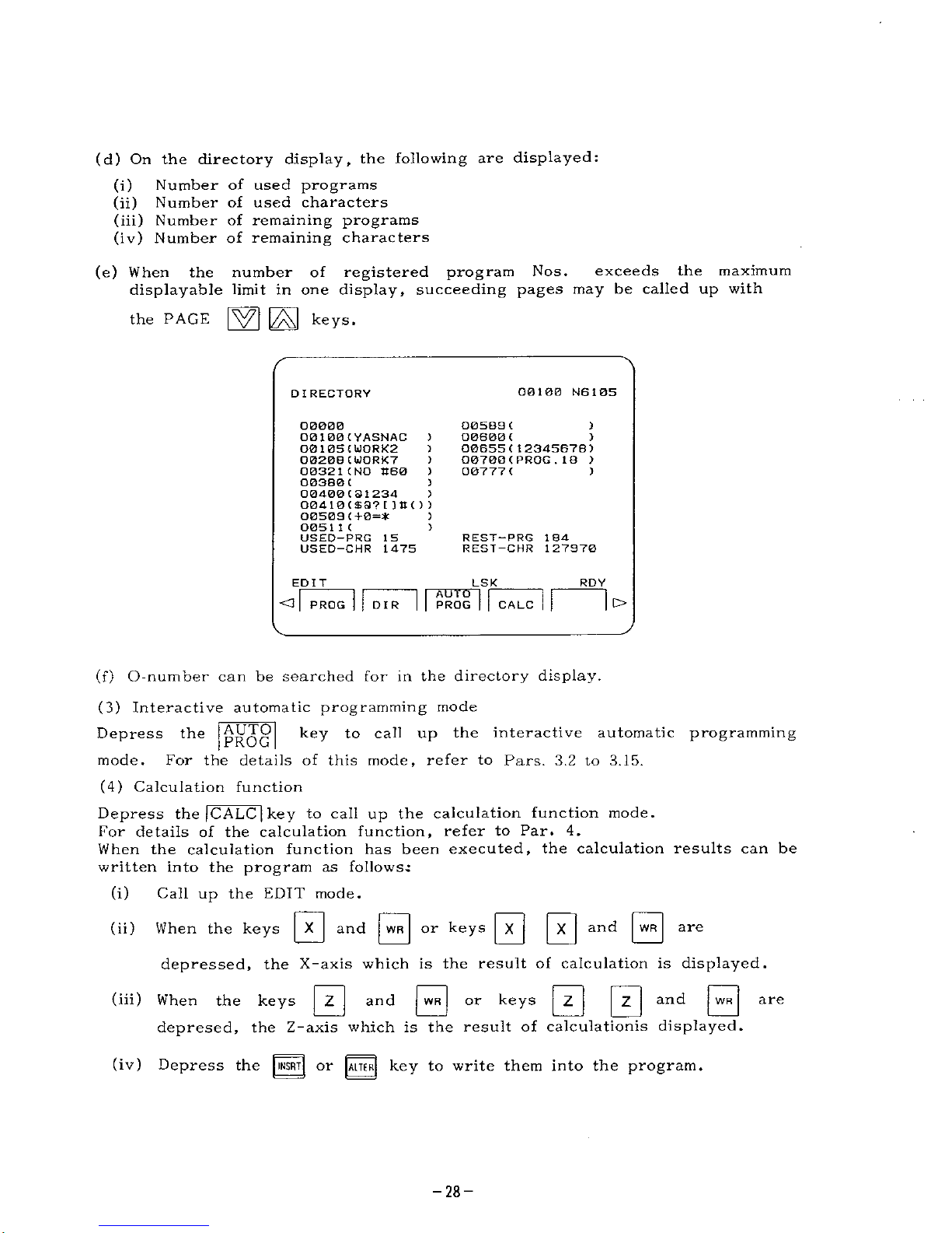
(d)
On
the
directory
display,
the
following
are
displayed:
(i)
Number
of
used
programs
(ii)
Number
of
used
characters
(iii)
Number
of
remaining
programs
(iv)
Number
of
remaining
characters
(e)
When
the
number
of
registered
program
Nos.
exceeds
the
maximum
displayable
limit
in
one
display,
succeeding
pages
may
be
called
up
with
GZ1
E3
keys-
the
PAGE
00100
N6105
DIRECTORY
O05B3
(
00600
(
00655
(
1
2345678)
00700
(
PROG
.
18
)
00777
C
1
00000
(
YASNAC
)
O0105OJORK2
)
O020BCWORX7
)
00321
(NO
K60
)
00380
C
00400(31234
>
00410
(
S3?
[
)•())
00508
(+0=*
0051
1
(
USED-PRG
15
USED—
CHR
1475
)
)
>
)
)
REST—
PRG
184
REST—
CHR
127970
RDY
EDIT
LSK
AUTO
PROG
<3
PROG
o
DIR
CALC
(f)
O-number
can
be
searched
for
in
the
directory
display.
(3)
Interactive
automatic
programming
mode
Depress
the
mode.
(4)
Calculation
function
Depress
the
|CALC
|
key
to
call
up
the
calculation
function
mode.
For
details
of
the
calculation
function,
refer
to
Par.
4.
When
the
calculation
function
has
been
executed,
the
calculation
results
can
be
written
into
the
program
as
follows.:
Call
up
the
EDIT
mode.
AUTO
PROG
key
to
call
up
the
interactive
automatic
programming
For
the
details
of
this
mode,
refer
to
Pars.
3.2
to
3.15.
(i)
|
X
|
and
|WR|
or
keys
|
X
[
|
X
|
and
|
WR
|
(ii)
When
the
keys
are
depressed,
the
X-axis
which
is
the
result
of
calculation
is
displayed,
s
0
0
0
0
(hi)
and
or
keys
depresed,
the
Z-axis
which
is
the
result
of
calculations
displayed.
When
the
keys
and
are
Depress
the
INSRT|
or
|ALTER[
key
to
write
them
into
the
program.
(iv)
-28-
Page 29
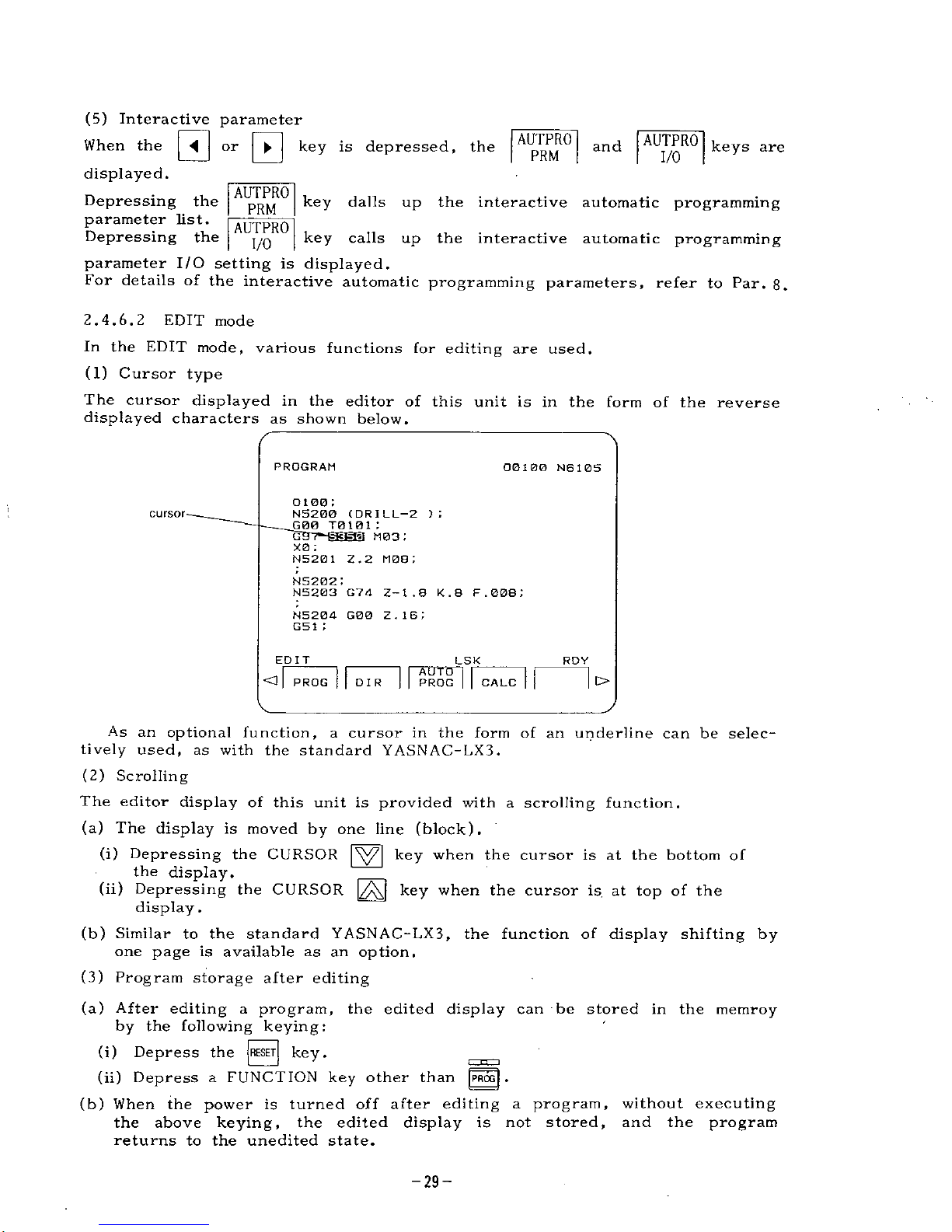
(5)
Interactive
parameter
When
the
displayed.
Depressing
the
parameter
list.
Depressing
the
parameter
I/O
setting
is
displayed.
For
details
of
the
interactive
automatic
programming
parameters,
refer
to
Par.
8.
0“'0
AUTPRO
AUTPRO
key
is
depressed,
the
and
keys
are
PRM
I/O
AUTPRO
key
dalls
up
the
interactive
automatic
programming
PRM
AUTPRO
key
calls
up
the
interactive
automatic
programming
I/O
2.
4.
6.
2
EDIT
mode
In
the
EDIT
mode,
various
functions
for
editing
are
used.
(1)
Cursor
type
The
cursor
displayed
in
the
editor
of
this
unit
is
in
the
form
of
the
displayed
characters
as
shown
below.
reverse
PROGRAM
00100
N610S
0100
;
N5200
(DRILL-2
)
;
G00
T0101
;
i
cursor
G
[3
M03
:
X0
;
N5201
2.2
MOB;
N5202
•
NS203
GY
4
2-1.8
K.8
F
.
008
;
N5204
G00
Z.
16;
G51
;
EDIT
LSK
ROY
All
TO
PROG
O
PROG
>
DIR
CALC
As
an
optional
function,
a
cursor
in
the
form
of
an
underline
can
be
selec¬
tively
used,
as
with
the
standard
YASNAC-LX3.
(2)
Scrolling
The
editor
display
of
this
unit
is
provided
with
a
scrolling
function.
(a)
The
display
is
moved
by
one
line
(block).
(i)
Depressing
the
CURSOR
|\Y7|
key
when
the
cursor
is
at
the
bottom
of
the
display.
(ii)
Depressing
the
CURSOR
key
when
the
cursor
is
at
top
of
the
display
.
(b)
Similar
to
the
standard
YASNAC-LX3,
the
function
of
display
shifting
by
one
page
is
available
as
an
option.
(3)
Program
storage
after
editing
(a)
After
editing
a
program,
the
edited
display
can
be
stored
in
the
memroy
by
the
following
keying:
(i)
Depress
the
|
RESET
[
key.
(ii)
Depress
a
FUNCTION
key
other
than
|PROG|
.
(b)
When
the
power
is
turned
off
after
editing
a
program,
without
executing
the
above
keying,
the
edited
display
is
not
stored,
and
the
program
returns
to
the
unedited
state.
-29-
Page 30
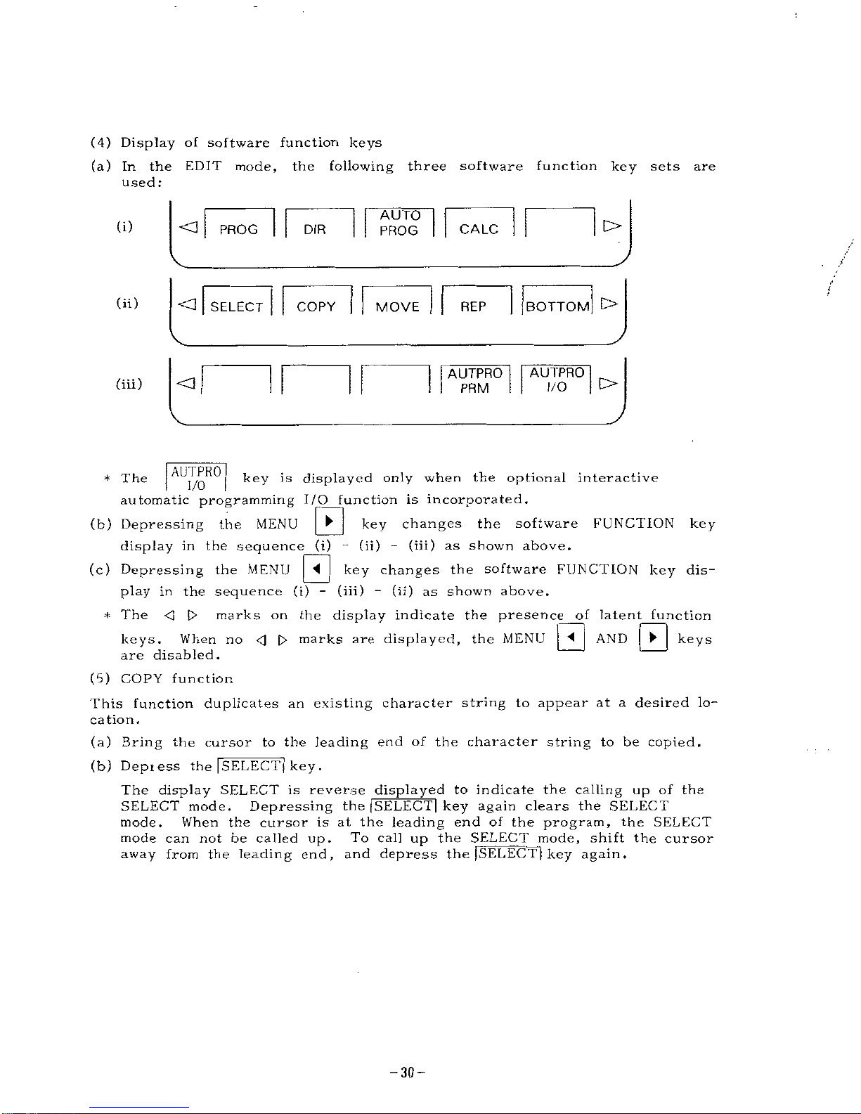
(4)
Display
of
software
function
keys
(a)
In
the
EDIT
mode,
the
following
three
software
function
key
sets
are
used:
AUTO
PROG
O
(i)
<3
DIR
CALC
PROG
/
(ii)
BOTTOM
C>
<3
SELECT
COPY
MOVE
REP
AUTPRO
AUTPRO
O
(iii)
O
I/O
PRM
AUTPRO
key
is
displayed
only
when
the
optional
interactive
automatic
programming
I/O
function
is
incorporated.
*
The
I/O
0
key
changes
the
software
FUNCTION
key
display
in
the
sequence
(i)
-
(ii)
-
(iii)
as
shown
above.
(c)
Depressing
the
MENU
play
in
the
sequence
(i)
-
(iii)
-
(ii)
as
shown
above.
marks
on
the
display
indicate
the
presence
_of
latent
function
keys
(b)
Depressing
the
MENU
J~<l
|
key
changes
the
software
FUNCTION
key
dis-
*
The
<]
t>
0
AND
\V\
When
no
0
0
marks
are
displayed,
the
MENU
keys
.
are
disabled.
(5)
COPY
function
This
function
duplicates
an
existing
character
string
to
appear
at
a
desired
lo¬
cation.
(a)
Bring
the
cursor
to
the
leading
end
of
the
character
string
to
be
copied.
(b)
Depiess
the
[SELECT]
key
.
The
display
SELECT
is
reverse
displayed
to
indicate
the
calling
up
of
the
SELECT
mode.
Depressing
the
|SELECT|
key
again
clears
the
SELECT
mode.
When
the
cursor
is
at
the
leading
end
of
the
program,
the
SELECT
mode
can
not
be
called
up.
To
call
up
the
SELECT
mode,
shift
the
cursor
away
from
the
leading
end,
and
depress
the
[SELECT]
key
again.
-30-
Page 31

(c)
Move
the
cursor
to
the
endof
the
character
string
to
be
copied.
The
selected
characters
are
all
reverse
displayed
to
indicate
the
selected
range.
00
100
N6
105
PROGRAM
0100;
N5200
(DRILL-2
)
:
G00
T0101
;
N5201
Z.2
M0B;
N5202
;
N5203
G74
Z-
1
.
8
K.8
F
.
008
;
N5204
G00
Z.16;
G51
;
EDIT
LSK
RDY
[BOTTOTI
£>
<3
ISELECTI
COPY
MOVE
REP
(d)
Depressing
the
I
COP
Y
I
key
stores
the
selected
character
string,
and
a
mark
appears
on
the
software
key
display.
The
selected
character
string
is
displayed
normally.
(e)
Move
the
cursor
to
where
the
copy
is
to
appear.
Not
only
the
selected
program
Nos.,
but
also
others
can
be
copied.
(f)
Depressing
the
ICOPY
I
key
displays
the
selected
character
string
at
the
selected
location.
(g)
While
a
"
*
"
is
dispiayed
on
the
I*
COPY
Isoftwsre
key,
the
same
character
string
can
be
copied
as
many
times
as
the
I*
COPY
I
key
is
depressed.
(h)
By
depressing
the
lORG
key
when
a
"
”
is
displayed
on
the
COPY!
software
key,
the
data
in
the
selected
character
string
are
cleared
and
the
"
*
"
disappears.
PROGRAM
O0I00
N6105
:
DI
00
;
N5200
(
DR
I
LL-2
1
G00
T0
1
0
1
;
G97
S350
M03;
X0
;
N5201
Z.2
M08;
:
N5202
I
G37
S350
M03;
X0H
N5203
G74
Z-
1
.
8
K.8
F
.
008
1
EDIT
<3
[SELECT]
I*
RDY
LSK
o
COPY
BOTTO
MOVE
REP
Note:
When
the
power
supply
is
turned
off,
the
selection
of
character
string
is
cleared,
and
the
**"
mark
disappears.
When
the
MOVE
function
is
used
after
the
COPY
function
setting,
the
character
string
selection
is
also
cleared.
When
the
cursor
is
moved
to
the
leading
end
of
the
program
in
the
SELECT
mode,
the
SELECT
mode
is
automatically
cancelled.
The
range
of
the
character
string
to
be
selected
is
up
to
1024
characters.
If
the
ICOPY
1
key
is
depressed
with
the
number
of
characters
exceeding
the
range,
warning
message
"AREA
OVER
!
*
is
displayed.
-31
-
Page 32

(6)
MOVE
function
This
functon
is
for
displacing
the
existing
character
string
to
other
locations
in
NC
program
editing.
(a)
Specify
a
character
string
to
be
moved
by
using
the
I
SELECT
I
key
,
as
with
the
ICOPYl
function.
(b)
Depress
the
iMOVEl
key
to
store
the
selected
character
string.
A
mark
IMOVEI
key
display.
The
reverse
displayed
character
string
appears
on
the
is
deleted.
(c)
Move
the
cursor
to
where
the
character
string
is
to
appear.
Not
only
the
selected
program
Nos.,
but
also
others
can
be
moved.
(d)
Depeessing
the
I*
MOVEl
key
displays
the
selected
character
string
at
the
selected
location.
(e)
While
a
"
*
"
is
displayed
on
the
I*
MOVEl
software
key,
the
same
character
string
can
be
displayed
as
many
times
as
the
l=k
MOVEI
key
is
depressed.
(f)
By
depressing
the
tORGl
key
when
a
"
*
"
mark
is
displayed
on
the
I*
COPY
I
software
key,
the
data
in
the
selected
character
string
are
cleared
and
the
"
*
"
mark
disappears.
O0100
N6105
PROGRAM
O100
;
N5200
(DRILL-2
):
G00
T0101
;
N5201
Z.2
M0B;
N5202I
G97
S350
M03
:
X0B
N5203
G74
Z-
1
.
B
K.B
F
.
008
;
N5204
G00
Z
.
16
;
G51
:
LSK
RDY
EDIT
<3
[sELEC
]
[BOTTOII
t>
COPY
1
ffcMOVE
REP
Note:
When
the
power
supply
is
turned
OFF,
the
selection
of
character
string
is
cleared,
and
the
*
*
"
mark
disappears.
When
the
COPY
function
is
used
after
the
MOVE
function
setting,
the
character
string
seleciton
is
also
cleared.
When
the
cursor
is
moved
to
the
leading
end
of
the
program
in
the
SELECT
mode,
the
SELECT
mode
is
automatically
cancelled.
The
range
of
the
character
string
to
be
selected
is
up
to
1024
characters.
If
the
ICOPY
I
key
is
depressed
with
the
number
of
characters
exceeding
the
range,
warning
message
"AREA
OVER
!
"
is
displayed.
-32-
Page 33

(7)
REPLACE
function
This
function
is
for
searching
a
specified
character
string
in
the
displayed
NC
program
and
for
changing
it
with
another
character
string.
(a)
Depressing
the
|
REP
|
key
displays
tTOLD
STRING:"
at
the
lower
left
area
of
the
display.
Key
in
the
character
string
to
be
replaced.
For
example,
to
change
"GOO",
key
and
0
G
0
WR
*
PROGRAM
00100
N6105
N5205
M0i;
MM
(FACE-
FREE-
ROUGH);
G50
S4000;
G00
T0202
;
G96
S700
M03;
N1301
X4.2
2.08;
N
1
302
G00
G41
X4.20Q
2.004;
N
1
303
G01
X.720
F.0i:
N
1
304
G51
;
IQLD
STRING
a
G00
EDIT
LSK
RDY
j
|*M0VE
|
<3
SELECT]
I
BOTTOM
l>
REP
COPY
(b)
"NEW
STRING:"
is
displayed
at
the
lower
left
area
of
the
display.
Key
the
character
string
to
replace
the
existing
one.
For
example,
to
write
"GOl,"
key
G
and
0
1
WR
•
PROGRAM
O0100
N6105
N5205
M01
;
grama
(FACE-
FREE-
ROUGH)
;
GS0
S4Q00;
G00
T0202;
G9B
S700
M03;
N1301
X4.2
Z.0B;
N
1
302
G00
G41
X4
.
208
2.004;
N
1
303
G01
X.72B
F.01;
N
1
304
G51
;
S
BMEjgBBBEH
G0
1
EDIT
LSK
RDY
O
(SELECT)
I
BOTTOM
t>
REP
•
COPY
*M0VE
-33-
Page 34

(c)
In
the
lower
left
area
of
the
display,
"YES.
NO.
ALL"
is
displayed,
and
the
cursor
moves
to
the
character
string
specified
in
(a).
(i)
Depressing
the
|Y|
key
replaces
the
character
string
specified
in
(a)
with
the
one
specified
in
(b).
When
the
same
character
string
as
specified
in
(a)
is
present
elsewhere,
the
cursor
moves
there,
and
11
YES.
NO.
ALL"
is
displayed
on
the
display.
No
more
character
string
specified
in
(a)
is
found,
the
replacing
function
ends.
|
N
|
key
causes
no
change
in
character
strings.
(ii)
Depressing
the
The
cursor
moves
to
the
next
position
of
the
same
character
string
specified
in
(a),
and
"YES.
NO.
ALL"
is
displayed
on
the
display.
If
more
character
string
specified
in
(a)
is
found,
the
replacing
function
ends
.
0
key
replaces
all
the
character
strings
displayed
on
(iii)
Depressing
the
the
display
with
the
one
specified
in
(b).
PROGRAM
O0100
NB
105
N5205
M01
;
N
1
300
(FACE-
FREE-
ROUGH);
G50
S4000;
[trara
T0202;
G96
S700
M03:
N1301
X4.2
2.08:
N
1302
G00
G41
X4.208
2.004;
N
1
303
G01
X.728
F.01
;
N
1
304
G51
:
Biaauiimw
EDIT
RDV
LSK
<1
|SELECT|
I
REP
*MOVE
COPY
(d)
Precaution
The
replacing
is
executed
in
units
of
words,
and
therefore
is
subject
to
the
following
restrictions:
(i)
The
character
string
to
be
keyed
when
"OLD
STRING:"
is
displayed
must
be
one
word
preceded
by
an
alphabet
character.
When
characters
other
than
an
alphabet
character
are
keyed
for
the
leading
character,
a
warning
"INPUT
ERROR"
is
displayed.
(ii)
A
character
string
ocntaining
two
or
more
addresses
(comment)
can
not
be
replaced
at
the
same
time.
For
example,
"O.D."
can
not
be
replaced
by
"I.D."
During
the
replacing
process,
the
PAGE
keys
and
the
CURSOR
keys
are
invalid
.
(8)
BOTTOM
function
Depressing
the
|
BOTTOM
|
key
brings
the
cursor
to
the
last
address
of
the
dis¬
played
programs.
(9)
Search
erase
function
This
function
is
for
erasing
the
portion
of
display
from
the
cursor
to
the
character
string
which
is
keyed
in.
-34-
Page 35

(a)
Bring
the
cursor
to
the
leading
end
of
the
character
string
to
be
erased.
(b)
Key
in
the
character
string
to
be
erased.
(c)
Depress
the
j
ERASE
j
key.
(d)
The
portion
from
the
cursor
to
the
keyed
in
character
string
is
erased.
(e)
The
cursor
moves
to
the
address
next
to
the
erased
block.
(f)
When
the
last
block
has
been
erased,
the
eursor
moves
to
the
address
immediately
beofore
the
erased
address.
(g)
The
address
to
be
erased
can
be
specified
in
any
of
the
following
three
methods,
as
with
the
address
search
function:
(i)
Key
in
the
word
(one
address
data)
to
be
erased.
In
this
case,
the
leading
zeros
can
be
omitted.
(ii)
Key
in
one
character
without
data.
(iii)
Key
in
the
data
to
be
erased
(up
to
32
characters),
after
depressing
the
|NEXT|
key
.
In
this
case,
leading
zeros
can
not
be
omitted,
(erasing
by
means
of
pattern
searching
function)
All
the
portion
between
the
cursor
position
to
the
keyed
in
character
string
is
erased,
and
if
the
keyed-in
character
string
contains
two
or
more
words,
only
up
to
the
first
word
of
the
keyed-in
string
is
erased.
(h)
An
example
of
erasing
is
shown
by
the
two
diagrams
below.
PROGRAM
00100
N6105
N5205
M01
:
CTE33
(FACE-
FREE-
ROUGH);
G50
S4000
:
G00
T0202;
G96
S700
M03;
Nisei
X4.2
z.oa:
;
N
1
302
G00
G41
X4.20B
Z
.
004
;
N
1
303
G01
X.72B
F.01;
N!
304
GS1
;
EDIT
LSK
RDY
ir
<1
PROG
o
DIR
PROG
CALC
00000
B
When
are
depressed.
00100
NS
1
05
PROGRAM
NS205
M01
;
E30HH
Z.08;
N1302
G00
G41
X4.208
Z.004;
N
1
303
G01
X.72B
F.01
:
N
1
304
GS1
;
G40
;
N
1
305
M01
;
N2100
(00-
CYCLE-
ROUGH)
:
EMI
_
O
PROG
LSK
ROY
AUTO
PROG
>
CALC
DIR
-35-
Page 36

(10)
Line
cursor
function
This
function
is
for
moving
the
cursor
by
one
line
(block)
at
a
time.
(a)
Depress
the
[NEXT|
key.
(b)
Depressing
the
CURSOR
|\ÿj
keys
moves
the
cursor
by
one
line.
(c)
To
return
to
the
word
(address)
by
work
move
function,
clear
the
NEXT
mode
by
one
of
the
following
methods:
(i)
Depress
the
|NEXT|
key
again.
(ii)
Depress
the
[RESET|
key.
(iii)
Depress
any
FUNCTION
key
other
than
the
PROG
FUNCTION
key.
(11)
Automatic
re-naming
function
of
O
No.
input
(a)
When
reading
in
programs
from
outside,
if
the
O
No.
of
the
program
and
the
keyed-in
O
No.
are
different,
the
keyed-in
O
No.
is
registered
for
that
program.
(b)
The
O
No.
of
the
input
program
is
automatically
re-named
to
the
keyed
O
No.
(c)
When
the
input
program
has
no
O
No.,
it
is
input
as
is,
and
no
re-naming
takes
place.
(d)
For
the
details
of
part
program
inputting,
refer
to
Par.
4.4
of
the
stan¬
dard
YASNAC-LX3
Manual.
(12)
Feed
eliminate
function
in
program
outputting.
When
outputting
part
programs
and
internal
data
from
the
NC
to
outside
units,
feed
is
eliminated
by
this
function.
(a)
Feed
is
eliminated
from
the
output
by
one
of
the
following
two
methods.
(i)
Derpess
the
|OUT|
key
in
the
output
procedure,
and
as
outputting
is
key.
When
the
|
CAN
|
key
is
depressed,
the
The
[CAN]
started,
depress
the
outputting
of
the
significant
data
of
[%,....]
starts
immediately.
feed
after
the
outputting
of
the
significant
data
is
also
eliminated
when
the
(ii)
Specifying
with
a
parameter
*
#6008
D4
•
#6008
D4
|
CAN
|
key
is
depressed.
1
:
No
feed
output
0
:
Feed
output
(b)
For
details
of
the
outside
I/O
operator
manipulations,
refer
to
Par.
4.7
of
the
standard
YASNAC-LX3
Manual.
(13)
Reset
function
during
outside
I/O
manipulation.
With
this
unit,
for
outside
I/O
manipulations,
the
|
RESET
j
key
depressed
except
in
the
following
cases:
(a)
When
ALARM
occurs.
(b)
When
WARNING
occurs.
need
not
be
(14)
Limitation
at
editing
•
Any
program
exceeding
40m
can
be
input
from
external
devices
but
cannot
be
displayed
or
edited.
If
an
attempt
to
display
such
a
program
is
made,
a
warning
message
"EDIT
MEMORY
FULL
\"
is
displayed
and
the
part
after
40m
cannot
be
displayed.
-36-
Page 37

•
Do
not
input
any
program
with
a
block
in
which
more
than
28
characters
of
only
numerals,
V'
,
"+"
or
continues.
2.4.7
Displays
with
jpos]
FUNCTION
Key
Various
POSITION
display
screens
are
called
up
by
the
following
keying:
(1)
Depress
the
j|o|j
FUNCTION
key.
One
of
the
following
screens
is
displayed
(a)
POSITION
"POSITION
(b)
POSITION
"POSITION
(c)
POSITION
"POSITION"
(d)
Program
restart
information
display
"PROGRAM
RETURN"
(e)
Stored
stroke
limit
residual
pulse
count
display
"STORED
STROKE
LIMIT"
(f)
Main
spindle
PG
pulse
count
display
"SPINDLE
COUNTER"
(g)
Servo
position
deviation
pulse
count
display
"ERROR
PULSE"
(h)
Command
pulse
cumulative
sum
register
display
"COMMAND
PULSE"
external
(EXTERNAL)"
absolute
(ABSOLUTE)"
collective
indication
Note:
The
display
(h)
is
made
only
when
the
SYSTEM
No.
switch
is
4.
(2)
Depressing
the
PAGE
lÿ7]
keys
switches
the
above
display
screens
sequentially
one
after
another.
(3)
For
details
of
the
above
display
screens,
refer
to
Par.
4.3.4.
1
through
4.
3.
4.
9
of
the
standard
YASNAC
LX3
Manual.
(4)
With
all
the
POSITION
FUNCTION
displays,
the
following
software
function
keys
are
displayed.
Depressing
one
of
these
software
keys
calls
up
the
corresponding
display
screens
directly
as
follows:
(a)
Depressing
I
EXT
I
(b)
Depressing
lABSl
(c)
Depressing
1
4
—
P
O
S
1
(d)
Depressing
|SPINDL|
key...
Spindle
PG
pulse
count
display
(5)
Depressing
the
turn
.
key...
POSITION
(EXTERNAL)
is
displayed
key...
POSITION
(ABSOLUTE)
is
displayed
key...
POSITION
collective
is
displayed
j~pggj
key
also
calls
up
these
four
displays
sequentially,
in
(6)
With
the
position
collective
display
screen,
the
follwoing
keying
resets
POSITION
EXTERNAL
alone
to
0.
0”r0
to
select
the
axis
to
be
reset.
(a)
Depress
ADDRESS
key
(b)
Depress
the
|
QRG|
key.
(c)
The
display
for
the
selected
axis
becomes
0.
(d)
This
display
resetting
keying
is
always
effective
including
the
motion
time
in
a
part
program
automatic
run.
-37-
Page 38

;
pn~i
2.
4.
8
Display
with
g)
FUNCTION
Key
(1)
Depress
the
|OFS|
key
to
call
up
the
OFFSET
display
screen.
(2)
For
the
display
and
writing-in
manipulation,
refer
to
Par.
4.3.5
in
the
standard
YASNAC
LX3
Manual-
(3)
With
this
unit,
depressing
the
following
software
function
keys
calls
up
the
respective
display
screens:
(a)
Derpess
WORK
SHIFT
key
...
Work
coordinate
system
shift
amount
display
TOOL
WEAR
(b)
Depress
(c)
Depress
(4)
Depressing
the
[
P0S
j
key
changes
the
above
displays
in
sequence
one
after
another.
key
.
.
.
Tool
offset
display
TOOL
SHIFT
key
...
Tool
coordinate
data
display
00100
NB
1
05
OFFSET
(TOOL—
WEAR)
R
Z
c
X
T
Ell
0
0
0 0
0
0
0
0
0
0
0
0
0
0
0?
0
0
03
0
04
0
0
0
05
POSITION
(EXTERNAL)
X
0
Z
0
MEMORY
I
WORK
|
SHI
FT
LSK
RDY
TOOL
SHIFT
TOOL
WEAR
PST
1
PST2
(5)
For
the
new
tool
setter
function,
the
setting
is
made
with
the
following
software
function
keys:
(a)
When
the
|
PST
1
|
key
is
depressed,
the
software
key
is
reverse
displayed,
and
tool
coordinate
memory
writing
is
enabled.
The
offset
display
screen
automatically
changes
to
the
one
for
the
current
turret
tool
No.
and
the
ini
LED
of
the
jOFj~j
FUNCTION
key
blinks.
(b)
Depressing
the
|
PST2|
key
reverse
displays
the
software
key
and
work
shift
amount
writing
is
enabled.
The
offset
screen
is
automatically
changed
to
the
work
shift
amount
screen.
gg
FUNCTION
key
The
LED
of
the
TOOL
WEAR
WORK
SHIFT
’
During
the
|
PST1
1
and
|
PST2
1
modes,
the
keys
are
disabled.
blinks
.
TOOL
SHIFT
(c)
For
details
of
the
new
tool
setter
function,
refer
to
Sect,
2
of
"YASNAC
LX3
Upgrading
Function
Operator's
Manual"
(TOE-C843-9.23)
.
and
-38-
Page 39

3.
INTERACTIVE
PROGRAMMING
3.
1
NC
UNIT
INTERNAL
CONFIGURATION
AND
FLOW
OF
INTERACTIVE
PROCESSES
(1)
The
NC
internal
memory
configuration
related
to
interactive
processes
is
shown
below.
NC
UNIT
INTERACTIVE
SECTION
NC
MAIN
SECTION
BACKUP
MEMORY
BACKUP
MEMORY
INTERACTIVE
PARAMETER
PARAMETER
HIGH
SPEED
WINDOW
INTERACTIVE
DATA
I
(NC
PROGRAM)
\~]
OFFSET
D
PART
PROGRAM
(INTERNAL
DATA)
END
RS-232C
RS
232C
As
shown
above,
the
NC
unit
is
composed
roughly
of
interactive
and
NC
main
sections.
The
interactive
data
(NC
program)
created
in
the
interactive
section
is
transferred
automatically
to
the
part
program
memory
in
the
NC
main
section
by
the
operation
"END".
Conversely,
however,
the
part
program
in
the
NC
main
section
cannot
be
read
out
to
the
interactive
section.
In
other
words,
the
data
flows
unidirectionally
from
the
interactive
to
NC
main
section.
-39-
Page 40

!
(2)
The
overall
flow
chart
for
the
compact
interactive
automatic
programming
function
is
shown
below.
Interactive
procedure
New
data,
old
data
Program
No.
setting
Material
shape
setting
Major
turning
menu
setting
Minor
lurning
menu
setting
Approach
setting
Finishing
Basic
data
setting
Grooving,
drilling,
threading
Finished
shape
setting
Program
insertion
Tool
retraction
setting
1
Interactive
procedure
end
manipulation
No
return
Returnable
Automatic
transfer
of
interac¬
tively
generated
program
to
part
program
memory
NO
Drawing
check
OK?
Correction
process
(old
data)
YES
Normal
automatic
operation
-40-
Page 41

(3)
The
interactive
programming
manipulation
for
various
turning
processes
(such
as
outside
rough
turning)
can
all
be
executed
in
the
unified
flow
consisting
of
approach
-
shape
setting
-
tool
retract.
3.
2
CALL
UP
OF
INTERACTIVE
MODE
By
the
following
manipulation,
the
interactive
mode
can
be
called
up
from
the
ordinary
NC
mode.
l
—
1
)
t
(a)
Depress
the
|PRC)G|
key.
The
program
function
display
is
called
up
and
the
following
software
function
keys
(FI
~
F5)
are
displayed.
AUTO
PROG
0
<3
DIR
PROG
CALC
f”1
0
0
E
F3
F4
F2
AUTO
PROG
(b)
Depress
the
key.
Now
the
interactive
mode
has
been
called
up.
3.
3
PROGRAM
NO.
SETTING
(FOR
NEW
DATA)
(1)
In
the
interactive
mode,
the
following
screen
is
displayed:
**
PROGRAM
NUMBER
**
N0000
O
Old
Da
t
a
2
New
Data
Program
number
=0
Conunen
t
=
(
)
MEMORY
LSK
RDY
ll
If
I
|E
END
NTER
Initially,
the
cursor
is
located
at
"1
Old
Data",
and
"1"
blinks.
of
the
display,
software
function
keys
are
displayed.
At
the
bottom
-41
-
Page 42

(2)
The
program
No.
of
the
program
to
be
newly
generated
is
set
by
the
fol¬
lowing
manipulations.
(a)
Depress
the
CURSOR
|ÿ7|
keys
to
bring
the
cursor
to
"
Now,
"2"
blinks.
_
2
New
Data".
Depress
the
|
ENTER
[
key.
(Note:
The
treatment
of
"1
Old
Data"
will
be
described
in
Sect.
5.)
Now,
the
cursor
is
at
"0
number".
(b)
Any
numbers
between
1
and
9999
can
be
set
as
the
program
No.
For
example,
and
00
0-
The
dis-
to
set
"100",
key
played
"Comment"
now
blinks.
(c)
Up
to
8
alphanumeric
characters
can
be
keyed
as
the
comment.
in
this
sequence.
To
input
"ABC",
key
jÿT]
|jT|
[CT|
[WR]
.
Comment
may
be
omitted.
(d)
Depressing
the
CURSOR
tAj
0
key
moves
the
Use
this
feature
to
keys
or
the
cursor
between
"Program
number"
and
"Comment".
correct
keying,
if
necessary.
(Note:
Depressing
the
|
END
|
key
calls
up
the
normal
NC
mode
again,
but
usually,
at
this
point,
further
manipulations
are
made
without
calling
up
the
normal
NC
mode
again.
(e)
Depress
the
|
ENTER|
key.
Now,
the
program
No.
and
comment
have
been
set.
(3)
Precautions
If
the
same
program
No.
keyed-in
has
been
registered,
the
keying
is
invalid,
and
the
message
"O
number
already
exist"
is
displayed.
Key
some
other
program
No.
-42-
Page 43

3.
4
SETTING
BLANK
SHAPE
(1)
When
a
program
No.
has
been
set,
the
following
is
displayed:
**
BLANK
SET
**
00000
N0000
O100B
O.
D.
1.
D.
Length
=
Fac
e
r
emo
va
1
=
Chucking
lgth=
Cen
ter
0
0
0
0
0
=
HBiB/1
:
Yes
MEMORY
LSK
RDY
1
|
[E
END
NTKR
(2)
The
blank
shape
is
set
through
the
following
keying:
For
example,
to
input
”4
inch",
key
|
4
|
and
|WR|
,
in
(a)
input
the
O.
D.
this
sequence.
The
"I.D."
in
the
display
starts
to
blink.
(b)
Input
the
"I.D."
To
input
"0.8
inch",
key
sequence
.
The
keying
of
I.D.
is
required
only
for
tubular
blanks.
For
other
blanks,
no
I.D.
need
be
input.
Where
bar
material
is
drilled
and
bored,
the
drill
diameter
is
input
auto¬
matically
as
the
I.D.
upon
completion
of
the
drilling
process
to
set
a
new
blank
.
The
"Length"
display
starts
to
blink.
(c)
Input
the
length.
For
"5.5
inch",
key
sequence
.
The
"Face
removal"
display
starts
to
blink.
(d)
Input
the
face
machining
allowance.
Input
the
allowance
from
material
face
to
program
reference
point.
This
defines
the
reference
point
"
©
"
posi¬
tion.
The
"Chucking
legh"
display
starts
to
blink.
(e)
Input
the
chucking
length.
This
is
the
length
of
the
blank
gripped
by
the
chuck.
With
external
jaws,
the
jaw
length
is
to
be
input,
and
with
the
internal
jaws,
"0"
is
to
be
input.
The
"Center"
display
starts
to
blink.
(f)
Input
the
use
or
no
use
of
the
center.
when
no
center
is
used,
and
key
0
0
and
,
in
this
0-
0-
0
and
0-
in
this
0
0.
,
when
a
center
is
used.
Key
-43-
Page 44

(g)
If
wrong
data
have
been
keyed-in,
move
the
cursor
to
the
item
in
question
and
key
the
correct
data.
with
the
CURSOR
[/ÿ\J
|ÿ7)
keys
or
the
jWRj
key,
(3)
Precautions
(a)
Turning
of
cast
blanks
With
cast
blanks
which
are
shaped
similar
to
the
finished
shapes,
the
"roughing
cycle"
such
as
G71
and
G72
involves
much
air
cutting
and
wastes
much
time.
turning
cycle"
in
the
course
of
the
interactive
programming,
or
manually
input
outside
the
interactive
mode,
on
the
programming
display
.
For
the
details
of
the
closed
loop
turning
cycle,
refer
to
Par.
2.8.25.4
of
"YASNAC
LX3
Instruction
Manual."
However,
where
the
turning
consists
only
of
one
roughing
and
one
finishing
cycle,
any
turning
menu
can
be
used.
For
details,
refer
to
Par.
3.6,
"MINOR
TURNING
MENU
SETTING."
In
the
above
case,
input
the
largest
blank
diameter
and
the
longest
blank
length
respectively
as
the
"O.D."
and
the
"Length".
For
these
blanks,
manually
input
the
G73
"closed
loop
(b)
Data
decimal
point
inputting
method
To
input
"10",
key
|1|
0
j
|WR|
,
To
input
"10.1",
key
in
this
sequence.
0
0
0-
0
0
•
or
0
0
0
•
in
this
sequence.
1
0
0
T
in
this
To
input
"0.1",
key
sequence.
(4)
|
MANUAL
|
key
The
|
MANUAL
|
key
is
a
select
key
for
the
use
of
the
CURSOR
keys
and
DATA
keys
in
the
upper
or
lower
part
of
the
display.
It
is
an
alternate
switch.
When
the
|
MAN
UAL|
key
has
been
depressed,
and
the
EDIT
mode
has
been
called
up,
the
following
edit
functions
are
available.
(i)
The
CURSOR
|Xÿ7|
keys
have
a
scrolling
function.
(ii)
Depressing
the
|NEXT|
key
displays
"NEXT"
in
the
upper
part
of
the
display.
In
this
state,
the
CURSOR
|ÿ\j
[
keys
function
as
line
cursor
keys.
(iii)
Search
erase
function
This
function
is
for
erasing
the
portion
between
the
current
cursor
posi¬
tion
and
the
to-be-searched
position.
Derpessing
the
keys
for
the
to-be-searched
string
and
the
ERASE
key,
erases
the
portion
between
the
initial
cursor
position
and
the
searched
characters
.
(iv)The
functions
of
the
ERASE
|
,
j
INSRT[
and
[AITER|
keys
For
details,
refer
to
"YASNAC
LX3
Instruction
Manual."
can
be
used.
-44-
Page 45

3.
5
SETTING
BY
VARIABLE
TURNING
MENU
(1)
When
the
blank
shape
setting
has
been
made,
the
following
menu
is
dis¬
played.
**
MENU
**
00000
N0000
O100H
O
Face
2
O.
D.
3
I.
D.
4Groove
5
Drill
6Th
read
!-cri
MEMORY
LSK
RDY
modify
im
JMANUALI
|E
END
EXIT
NTER
With
this
menu,
the
following
processes
are
included:
"Face",
"O.D.",
Basically,
other
turning
processes
are
not
programmable
in
the
interactive
mode.
"Drill"
,
"Thread"
"Groove"
,
(2)
Setting
is
executed
by
the
following
keying:
(a)
To
make
a
selection,
move
the
cursor
to
the
intended
menu
with
the
CURSOR
or
the
J
WH
|
key.
The
same
selection
can
be
effected
when
the
menu
No.
is
directly
specified
with
the
DATA
j*-[|
to
j1
g
j
keys.
(b)
To
return
to
the
preceding
display,
that
is,
the
blank
shape
setting
dis¬
play,
depress
the
|
EXIT
|
key.
When
editing
in
the
upper
part
of
the
screen
is
desired,
depress
the
|MANUAL|
key.
Depressing
it
once
reverse
displays
it,
and
depressing
again
returns
it
to
normal.
key
is
for
selecting
between
the
insertion
of
new
NC
programs
generated
by
interaction
and
the
changing
of
the
previously
input
processes.
the
new
data,
the
insert
mode
is
set
as
the
initial
value,
and
with
the
old
data,
the
change
mode.
Note
that
this
mode
is
switched
only
in
the
variable
turning
process
menu-.
Depress
the
|
END
|
key
to
cancel
the
interactive
mode.
Now
the
variable
turning
menu
has
been
set.
(c)
Depress
the
|
ENTER
|
key
after
setting
with
the
menu.
IA1
IVl
keYs
dify
I
mo
The
insert
With
(3)
Process
list
The
process
list
indicates
all
processes
of
a
program
currently
edited
for
interaction.
Each
process
is
expressed
with
the
turning
menu
numbers
of
the
variable
and
detailed
menu
displays.
Additionally,
each
process
name
at
the
current
cursor
position
in
each
process
list
is
displayed.
For
example,
a
process
with
variable
menu
No.
4
and
detailed
menu
No.
3
indicate
rough
O.D.
drilling.
-45-
Page 46

(
a
)
Up
to
36
processes
can
be
registered.
(b)
If
the
number
of
processes
exceeds
12
or
24,
they
are
displayed
on
the
second
and
third
pages
and,
at
the
same
time,
the
number
of
pages
is
displayed
on
the
screen.
(c)
If
the
number
of
processes
exceeds
36,
they
are
inserted
into
the
program
but
are
not
reflected
in
the
process
list.
(d)
When
process
deletion
or
the
like
is
performed
by
using
the
MANUAL
key,
it'
is
not
reflection
in
the
process
list.
(e)
The
name
of
the
process
where
the
cursor
is
currently
located
is
displayed
in
the
process
list.
(
f
)
If
any
of
the
following
operations
is
performed,
the
process
list
cannot
correspond
to
the
programs.
•
More
than
36
processes
are
created.
•
Several
processes
with
the
same
menu
are
created
and
some
of
them
are
deleted.
3.
6
SETTING
WITH
DETAILED
TURNING
MENU
(ROUGHING,
FINISHING)
When
the
setting
is
completed
with
the
VARIABLE
turning
menu,
the
respective
detailed
turning
menus
are
displayed.
3.6.1
When
Facing
is
Set
(1)
The
following
display
is
called
up.
(a)
Initially,
the
cursor
is
located
at
"Free
rough".
(b)
With
the
Face
menu,
the
fol¬
lowing
four
menus
are
available:
(i)
Face
rough
This
is
a
canned
facing
cycle
using
G72.
(ii)
Face
fin
This
is
the
finishing
cycle
of
the
shape
input
for
roughing
by
G70.
**
MENU
**
00000
N0000
O100B
Ef
Free
r
o
ash
2
Face
fin
1
Face
rough
4
Free
fin
-1
G7
0
G7
ON
o
n
MEMORY
LSK
ROY
t
IPROCES
r
EX
TT
I
[SEARCH]
pi
I
P
END
ANUAL
NTER
(iii)
Free
rough
The
NC
program
is
generated
with
only
GOO
and
G01.
For
the
input
finishing
shape,
one
roughing
cycle
is
executed
on
the
input
finishing
shape
with
a
specified
finishing
allowance.
The
free
rough
turning
is
mainly
suited
to
face
roughing
with
small
turning
allowance
or
for
cast
blanks.
It
is
not
suitable
for
blanks
with
heavy
turning
allowance.
For
these
blanks,
use
face
rough
which
generates
canned
cycle
NC
programs.
(iv)
Free
fin
The
finishing
of
the
shape
input
by
the
free
rough
with
only
GOO
and
G01
.
It
is
not
a
canned
cycle.
(2)
Detailed
turning
menu
is
set
with
the
following
operation.
(a)
Select
the
desired
menu
with
the
CURSOR
|ÿ\J
keys,
key.
The
same
effect
is
obtained
when
the
desired
menu
No.
is
directly
keyed
with
the
data
keys
0
or
the
G>0-
-46-
Page 47

(b)
To
return
to
the
previous
display,
(the
variable
turning
menu),
depress
the
|
EXIT
|
key.
Depress
the
|
MANUAL
|
key
when
editing
in
the
upper
part
of
the
display
is
desired.
Depressing
it
reverse
displays
the
key,
and
depressing
it
again
returns
it
to
normal.
To
cancel
the
interactive
mode,
depress
the
|
END
|
key.
When
the
insert
setting
has
been
selected
for
the
variable
turning
menu,
the
F3
software
key
indicates
Depressing
the
[modify
I
key
in
the
insert
PROCES
I
SEARCH
[
'
key
detects
the
leading
ends
of
the
processes
one
after
PROCES
SEARCH
another.
After
detecting
the
last
program,
depressing
the
key
again
detects
the
first
program.
This
function
is
used
when
inserting
a
new
process
between
two
existing
processes.
When
the
modify
setting
has
been
selected
for
the
dify
mo
key
in
the
insert
modify
indicating
the
variable
turning
menu,
the
F3
software
key
shows
|
insert
[
’
current
mode.
However,
mode
modification
is
disabled
in
the
detailed
turning
menu,
and
accordingly,
the
F3
key
is
disabled.
\
(c)
After
selecting
the
turning
menu
depress
the
|
ENTER
|
key.
detailed
turning
menu
has
been
set.
(3)
Precaution
When
finishing
is
set
with
out
a
roughing
setting,
warning
message
"Rough
cutting
data
does
not
exit"
is
displayed.
Set
a
roughing
process.
Now,
the
3.
6.
2
When
O.D.
Turning
is
Set
(1)
The
following
display
is
called
up.
In
this
menu,
the
following
four
processes
are
available.
(i)
O.D.
rough,
(ii)
O.D.
fin,
(iii)
Free
rough
and
(iv)
Free
fin.
00000
N0000
MENU
**
N
1
304
G51
:
G40
;
N
1
305
M01
;
H
4
Free
fin
9
Free
rough
2
O.
D.
fin
1
CX
D.
rough
l
G7
ONo
n
G7
0
For
detailed
descriptions
refer
to
Par.
3.6.1,
"When
Facing
has
been
Set.
"
RDY
LSK
MEMORY
INTER
EARCI
1ANUAL|
EXIT
END
(2)
The
setting
of
the
menus
is
the
same
as
in
Par.
3.6.1,
been
Set".
as
for
facing.
(3)
Precautions
Refer
to
Par.
3.6.1,
"When
Facing
has
been
Set".
"When
Facing
has
The
functions
of
the
software
function
keys
are
also
the
same
-47-
Page 48

3.6.3
When
I.D.
Turning
is
Set
(1)
The
following
display
is
called
up,
O0000
N0000
**
MENU
**
mum
;
N
1
300
(FACE-
FREE-
ROUGH);
G50
S4000;
G00
T0101
;
G96
S
1
20
M03;
D
I.
D.
rough
2
I*
a
fin
3
Free
rough
4
Free
fin
G7
ON
o
n
G70
RDY
MEMORY
LSK
no
di
i
y
EXIT
|
|i
n
s
e
r
t|
1ANUAL
ENTER
END
the
following
four
processes
are
available:
(iii)
Free
rough,
and
For
detailed
descriptions
refer
to
Par.
3.6.1
(2)
The
setting
of
the
menus
is
the
been
Set".
as
for
facing.
(3)
Precautions
Refer
to
Par.
3.6.1,
"When
Facing
has
been
Set".
In
this
menu,
(i)
I.D.
rough,
(iv)
Free
fin,
(1),
(b),
"Facing",
same
as
in
Par.
3.6.1,
"When
Facing
has
The
functions
of
the
software
function
keys
are
also
the
same
(ii)
I.D.
fin,
3.
6.
4
When
Grooving
is
Set
(1)
The
following
display
is
called
up.
**
MENU
**
00000
N0000
imim
;
N
1
300
(FACE-
FREE-
ROUGH);
G50
S4000;
G00
T0101
;
G96
SI
20
M03;
H
O.
D.
“i_r
2
O.
D.
groove
fin
3
Face
4
Face
groove
fin
J
4
5
X.
D.
6
I.
D.
groove
fin
LSK
RDY
MEMORY
|m
o
fl
i
i
y
i
END
EX
IT
|insert|
plANUAL|
[ENTER
In
this
menu,
the
following
six
processes
are
available:
-48-
Page 49

(i)
O.D.
O.D.
grooving
canned
cycle
using
G75
(ii)
O.D.
groove
fin
O.D.
groove
finishing
with
GOO
and
G01,
of
the
shape
input
by
O.D.
cycle.
(iii)
Face
Face
groove
canned
cycle
using
G74
(iv)
Face
groove
fin
Finishing
cycle
with
GOO,
G01,
of
the
shape
input
by
face
grooving
cycle.
(v)
I.D.
I.D.
groove
canned
cycle
using
G75
(vi)I.D.
groove
fin
Finishing
cycle
with
GOO,
G01,
of
the
shape
input
by
I.D.
grooving
cycle.
(2)
The
setting
of
the
menus
is
the
same
as
in
Par.
3.6.1,
"When
Facing
has
been
Set".
The
functions
of
the
software
function
keys
are
also
the
same
as
for
facing.
(3)
Precautions
Refer
to
Par.
3.6.1,
"When
Facing
has
been
Set."
3.
6.
5
When
Drilling
is
Set
(1)
The
display
at
right
is
called
up.
In
this
menu,
the
following
three
processes
are
available.
(i)
Drill
pat
1
Drilling
with
G01,
and
drilling
through
to
the
end.
No
canned
cycle
is
used.
(ii)
Drill
pat
2
Using
the
G74
canned
cycle,
the
drill
is
retracted
through
the
preset
distance
during
drilling
.
**
MENU
**
00000
N0000
lilfclsj;
N
1
300
(FACE-
FREE-
ROUGH);
G50
S4000:
G00
T0101
;
G96
SI
20
M03
:
IDril
l
pat
I
2D
r
i
1
1
pat
2
8
Dr
i
1
1
pat
3
MEMORY
LSK
RDY
jiire.FTn
r
[insert)
END
EXIT
ANUAL
ENTER
(iii)
Drill
pat
3
Using
the
G74
canned
cycle,
the
retraction
distance
setting
is
neglected
and
each
time,
the
drill
is
withdrawn
to
the
approach
point.
(2)
The
setting
of
the
menus
is
the
same
as
in
Par.
3.6.1,
"When
Facing
has
been
Set".
The
functions
of
the
software
function
keys
are
also
the
same
as
for
facing.
-49-
Page 50

3.
6.
6
When
Threading
is
Set
(1)
The
following
display
is
called
up.
00000
N0000
**
MENU
**
[uisiii
:
N
1
300
(FACE-
FREE-
ROUGH)
:
G50
S4000)
G00
T0101
;
G96
S
1
20
M03;
4
I.
D.
taper
2
I.
D.
thread
3
O.
D.
taper
0
O.
D.
thread
RDY
LSK
MEMORY
Birasmu
|
i
n
|inser
t)
jyiANUAUj
(E
NTER
END
EXIT
In
this
menu,
the
following
four
processes
are
available.
(i)
O.D.
thread
Using
G76,
the
program
cuts
external
straight
threads.
(ii)
I.D.
thread
Using
G76,
the
program
cuts
internal
straight
threads.
(iii)
O.D.
taper
Using
G76,
the
program
cuts
external
taper
threads.
(iv)
I.D.
taper
Using
G76,
the
program
cuts
internal
taper
threads.
(2)
The
setting
of
the
menus
is
the
same
as
in
Par.
3.6.1,
"When
Facing
has
been
as
for
Set".
The
functions
of
the
software
function
keys
are
also
the
same
facing
.
(3)
Precautions
In
cutting
threads,
the
following
turning
processes
cannot
be
programmed
in
the
interactive
mode:
(a)
Variable
pitch
threads
(b)
Multiple
start
threads
-50-
Page 51

3.
7
SETTING
OF
APPROACH
3.
7.
1
Setting
Approach
for
Facing,
O.D.
and
I.D.
Turning
(1)
When
the
detailed
menu
setting
is
completed,
the
following
display
is
called
up.
**APPROACH**
FACE
FREE
ROU
00000
N0000
01
00B
d
.
2000
Ge
a
r
=BHSHH/1
:
Hi
g
h
.
800
Ap
proach
X
=
2:Low
L
=
Turn=!
Tool
no
—
Surf
speed=
Spin
speed=
Spin
max
=
1
;
Rev
erse
Oil
=B§ISB/l:Of
f
Wo
r
k
=1«»3/
1
:L/2
:Of
f
LSK
RDY
MEMORY
i
t
mo
d
l
f
y
VLANUAL
NTER
EXIT
(a)
With
this
display,
the
tool
approaches
from
the
EXT
origin
or
the
machine
origin,
etc.
to
the
turning
start
point.
In
addition,
auxiliary
function
and
manual
input
items
are
mixed.
(b)
In
this
display,
both
automatically
determined
items
and
manual
input
items
are
mixed.
(c)
For
the
facing,
external
and
internal
machining,
the
approach
data
is
common
.
For
example,
approach
data
are
set
for
a
facing,
these
data
set
in
the
last
procedure
are
also
indicated
when
the
external
or
interanl
turning
display
screen
is
called
up.
With
these
processes,
once
approach
data
are
set,
the
same
data
are
indi¬
cated
in
all
other
displays,
and
only
different
points
need
to
be
set.
(d)
The
selected
turning
menu
is
displayed
at
the
top
center
part
of
the
screen
.
(2)
Set
various
items
by
the
following
keying:
(a)
The
approach
points
X
and
Z
are
automatically,
determined
on
the
basis
of
the
blank
shape
and
the
clearance
of
the
interactive
parameter.
They
can
also
be
manually
modified.
However,
for
face
finishing,
external
finishing
and
internal
finishing,
the
approach
point
is
automatically
set
by
the
final
block
coordinate
values
for
the
respective
roughing
and
finishing
shapes.
(b)
Inputting
tool
No.
For
example,
to
use
tool
No.
0
"01"
and
offset
No.
"02",
depress
000
in
this
sequence.
The
"Surf
speed"
display
is
now
blinking.
-51
-
Page 52

(c)
Inputting
surface
speed
or
spindle
speed
Either
surface
speed
or
spindle
speed
can
be
input.
Inputting
a
surface
speed
value
generates
a
surface
speed
constant
control
ON
type
NC
program.
Inputting
a
spindle
speed
value
generates
a
surface
speed
constant
control
OFF
type
NC
program.
For
example,
to
input
"200
rpm",
depress
j2j
|
|
0
j
|
WR
|
in
this
sequence.
When
a
value
is
input
for
surface
speed,
no
value
can
be
input
as
spindle
speeds.
When
a
surface
speed
has
been
set,
and
a
spindle
speed
is
still
desired
to
be
input,
depress
the
|ORG|
key
after
bringing
the
cursor
to
"Surface
speed"
to
"dump"
the
surface
speed
data,
and
key
the
spindle
speed
value.
Conversely,
where
a
spindle
speed
value
has
been
set,
and
a
surface
speed
is
desired
to
be
set,
"dump"
the
spindle
speed
data
by
depressing
the
|
QRG|
key
with
the
cursor
on
the
"Spin
speed",
and
then,
input
a
surface
speed.
"Spin
max"
starts
to
blink.
(d)
Inputting
spindle
maximum
speed
Depress
the
maximum
spindle
speed
DATA
keys
and
the
For
example,
to
input
"3000
rpm",
j
WR
|
key
.
depress
j'3j
[ÿj
p0~|
|~WR~[
in
this
sequence.
Then,
a
G50S****
spindle
speed
clamp
NC
program
is
output.
Although
the
maximum
spindle
speed
need
not
be
input,
if
it
is
not
input,
no
G50S****
NC
program
is
output.
Now,
the
"Gear"
display
in
the
screen
starts
to
blink.
(e)
Inputting
gear
The
initial
setting
for
"Gear"
is
"0".
Depress
the
following
DATA
keys
as
required.
For
"off":
depress
For
"high
speed":
depress
For
"low
speed":
depress
0-
co¬
rn-
If
no
change
from
the
initial
setting
is
needed,
move
the
cursor
with
the
CURSOR
0
W
key
or
the
key.
Now,
the
"Turn"
display
on
the
screen
starts
to
blink.
(f)
Inputting
turning
direction
The
initial
setting
for
turning
direction
is
"0".
0
depress
|
1
j
Depress
to
select
forward
run,
and
to
select
reverse
run.
Now,
the
"Oil"
display
on
the
screen
starts
to
blink.
-52-
Page 53

(g)
Inputting
cutting
oil
use
selection
The
initial
setting
for
"Oil"
is
"0".
0-
To
use
cutting
oil,
depress
and
to
use
no
cutting
oil,
push
Now,
the
"Work"
display
on
the
display
starts
to
blink.
(h)
Inputting
workpiece
position
The
workpiece
position
means
that
side
of
the
advancing
tool
on
which
the
workpiece
is
present.
This
setting
is
used
as
data
in
tool
edge
radius
compensation
.
The
initial
setting
for
workpiece
position
is
automatically
set
by
turning
menus
as
follows:
•
Facing:
right
•
External
turning:
left
•
Internal
turning:
right
To
change
these
setting,
Depress
|
0
|
for
"right",
Depress
|
1
j
and
Depress
|2|
for
"none"
.
WORK
-
LEFT
WORK
-
RIGHT
WORK
for
"left"
When
"none"
is
selected,
an
NC
program
with
tool
edge
radius
compensa¬
tion
OFF
is
generated.
(i)
To
change
the
data
for
various
items
,
move
the
cursor
to
the
respective
position
with
the
CURSOR
|ÿj
keys
or
the
I
WR
I
Depressing
the
|onG|
maximum
speed
on
the
left
half
of
the
screen
disappear.
(j)
Depress
the
[ENTER]
key.
Now,
the
approach
data
have
been
set,
and
a
program
is
generated
in
the
upper
part
of
the
display.
(3)
Precautions
All
the
setting
items,
except
for
the
spindle
maximum
speed
and
either
of
"Surf
speed"
or
"Spin
speed",
must
be
input.
If
some
items
are
not
set,
"Item
data
is
missing"
.is
displayed.
In
this
case,
input
the
missing
items,
and
depress
the
|
ENTER
|
key
again
.
key.
key
makes
the
items
from
Approach
X
to
spindle
-53-
Page 54

3.
7.
2
Setting
Approach
for
Grooving
(1)
For
grooving,
after
setting
the
detailed
turning
menus,
the
following
dis¬
play
is
called
up.
Initially,
the
cursor
is
found
at
"Approach
X".
case,
since
the
approach
point
is
not
automatically
set,
a
proper
approach
point
must
be
input
according
to
the
drawing.
This
input
approach
X
becomes
the
starting
point
for
grooving.
In
this
**APPROACH**
OD
GROV
ROUGH
00000
N0000
O100H
Gear=mWBH/l
:
High
2
:
L
ow
Turn-
AKW
1
iReverse
Oil
=Bim/l
:
Of
f
Approach
X12
Tool
no
=
Su
rf
speed-
Spin
Speed-
Spin
max
—
RDY
LSK
MEMORY
mod
lTy
i
|E
MANUAL
NTER
EXIT
(2)
For
the
setting
methods
for
various
items,
refer
to
Par.
3.7.1,
"Setting
Approach
for
Facing,
O.D.
and
I.D.
Turning."
(3)
Precautions
Refer
to
Par.
3.7.1
(3),
"Precautions".
3.7.3
Setting
Approach
for
Drilling
(1)
With
the
drilling
screen,
when
the
detailed
turning
menu
has
been
set,
the
display
shown
below
is
called
up
automatically.
In
the
case
of
drilling,
since
the
approach
point
not
automatically
set,
the
grooving
approach
point
must
input
in
accordance
with
the
drawing.
This
approach
Z
point
becomes
the
starting
point
for
drilling.
(2)
For
the
setting
methods
for
the
respective
items,
refer
to
Par.
3.7.1,
"Setting
Approach
for
Facing,
O.D.
and
I.D.
Tur¬
ning".
However,
"Spin
speed"
is
calculated
by
"Drill
diam"
and
"Surf
speed",
and
displayed.
(3)
Precautions
When
the
drill
diameter
and
the
surface
speed
are
input,
the
spindle
speed
is
automati¬
cally
determined,
and
dis¬
played
.
When,
the
drill
diameter
and
the
spindle
speed
are
input,
the
surface
speed
is
automati¬
cally
calculated,
and
dis¬
played
.
If
some
setting
items
are
not
set,
"Item
data
is
missing"
is
displayed
.
**APPROACH*:S:
DRILL
PAT
3
00000
N0000
Ol
00H
Gear
=HHSS9/1
.High
2
:
L
o
w
Turn
=
EM
B
1
iReverse
Oil
=[fflaa/l:Off
Ap
p
roach
Z
=
Tool
no
-
Drill
d
i
am-
Surf
speed=
Spin
speed2
MEMORY
RDY
I
P
}
mo
d
l
f
y
EXIT
(
MANUAL
NTER
-54-
Page 55

3.
7.
4
Setting
Approach
for
Threading
(1)
With
the
threading
display,
when
the
detailed
turning
menu
has
been
set,
the
display
shown
below
is
called
up
automatically.
00000
N0000
**APPROACH**
OD
THREAD
1008
Gear
=
HHctlSl/
1
:
High
2
:
Low
Turn
—
1
:
Re
ve
rse
Oil
=—
BI/1:
Off
Ch
am
f
Rr=BIB
SI7I/I
:
Of
f
Approach
X=
Z
=
Tool
no
-
Spin
speed=
RDY
MEMORY
LSK
Ik
mo
d
l
f
y
NTER
MANUAL
EXIT
In
the
case
of
threading,
since
the
approach
point
is
not
automatically
set,
the
grooving
approach
point
must
be
input
in
accordance
with
the
drawing,
This
approach
point
becomes
the
starting
point
for
threading.
(2)
For
the
setting
methods
for
the
respective
items,
refer
to
Par.
3.7.1,
"Setting
Approach
for
Facing,
O.D.
and
I.D.
Turning".
(3)
Precautions
Refer
to
Par.
3.7.1
(3),
"Precautions".
3.
8
SETTING
OF
BASIC
DATA
When
the
approach
point
has
been
set,
a
display
for
all
the
basic
data
values
corresponding
to
the
detailed
turning
menu
is
called
up.
Except
for
"threading"
and
"drilling"
and
for
finishing
commanded
by
the
respective
detailed
turning
menus,
this
display
is
available.
In
this
display,
the
finishing
allowance,
depth
of
cut,
required
for
setting
before
the
finish
shape
display
are
set.
values
are
automatically
set
on
the
basis
of
the
interactive
parameters,
but
can
be
modified
when
required.
feedrate,
etc.
All
the
data
3.
8.
1
When
Face,
O.D.
and
I
D.
Roughing
has
been
Set
(1)
The
display
right
is
called
up.
The
tool
No.
of
the
current
tool
is
displayed
at
the
upper
right
area
of
the
display.
**B.
DATA**
FACE
ROUGH
T0100000
N0000
shown
at
the
G50
S2000;
G00
T0101
;
G9B
SI
20
(103;
N1L01
X100.2
Z.00
1108
;
H
Fin
allowance
U
=
W
=
Depth
of
cut
D
=
Feedrate
80
40
.
800
.
100
F
=
MEMORY
LSK
RDY
|
|mo
d
i
f
y
EXIT
|
u
J
r1
I
k
ANUAL
INTER
-55-
Page 56

(2)
In
this
display,
all
the
items
have
been
automatically
set.
(a)
To
modify
the
values,
move
the
cursor
to
the
respective
position
with
the
CURSOR
|ÿ7j
keys
or
the
|~WR
J
key.
(b)
To
return
to
the
previous
display,
that
is,
the
approach
setting
display,
depress
the
[EXIT]
key.
Changing
the
approach
data
and
depressing
the
I
ENTER
|
key
sets
a
new
approach
point.
Depress
the
|
MANUAL
|
key
for
moving
the
cursor
in
the
upper
part
of
the
display
for
editing.
modify
Since
mode
changing
is
key
is
displaying
the
current
mode.
disabled
on
the
basic
data
display,
the
F3
key
is
ineffective.
(c)
Depress
the
|
ENTER|
key.
Now,
the
basic
data
values
have
been
set.
The
3.
8.
2
When
Face,
O.D.
and
l.D.
Free
Roughing
has
been
Set
The
setting
is
the
same
as
in
Par.
3.8.1,
except
that
no
"Depth
of
cut"
is
displayed.
3.
8.
3
When
Grooving
Has
Been
Set
(1)
The
display
shown
below
is
called
up.
**B.
DATA**
OD
GROV
ROUGH
T
0a
O0000
N0000
N4
1
00
(OD-
GROOVE-
ROUGH);
G50
S200;
G00
G40
T0404
;
N4101
G96
S20
M03;
H
Fin
allowance
U
=
W
=
De
p
thofcut
D
=
Re
treat
No.
of
steps
Feedrate
80
40
.
000
40
1
F
=
32
MEMORY
LSK
ROY
4
k
mod
I
f
EXIT
NTER
VLANUA
The
retreat
distance
displayed
in
this
display
is
the
one
in
the
NC
setting.
If
the
retreat
distance
is
modified
in
this
display,
the
one
in
the
NC
set¬
ting
is
automatically
modified.
However,
if
the
NC
is
running
on
memory
when
the
j
ENTER
|
key
is
depressed
on
the
basic
data
display,
the
setting
is
modified
after
the
com¬
pletion
of
the
run.
(2)
For
the
basic
data
setting,
refer
to
Par.
3.8.1.
-56-
Page 57

3.
9
SETTING
FINISH
SHAPE
When
the
setting
of
the
basic
data
has
been
made,
the
finish
shape
display
is
called
up
according
to
the
variable
turning
menu.
With
facing,
O.D.
turning
and
I.D.
turning,
the
workpiece
shape
is
to
be
input
with
straight
lines,
circular
arcs,
chamfers
and
rounding.
As
the
input
data
is
graphically
displayed
on
the
display,
visual
checking
is
possible.
With
grooving,
drilling
and
threading,
the
finish
shape
is
set
while
data
values
are
input
in
response
inquiries
message.
3.
9.
1
When
Face,
O.D.
and
I.D.
have
been
Set
(1)
The
display
shown
below
is
called
up.
Initially,
the
software
function
|
LINEAR|
key
is
reverse
displayed.
**SHAPE**
OD
ROUGH
T01
00000
N0000
End
pos.
X:
=|
Zj
=
x
z
MEMORY
LSK
RDY
I
BLOCK
I
|
(ENTER
I
t>
IE
CHAM-
FER
<
LINEAR
ARC
OUND
(a)
The
displayed
point
"
.
"
is
the
approach
point.
Program
is
to
be
written
along
the
tool
path
starting
from
this
point.
(b)
The
mark
"
®
11
indicates
the
program
origin,
which
is
(0,
0)
in
the
abso¬
lute
coordinate
system.
This
position
shifts
with
the
face
removal
allowance
data.
(c)
The
"("
line
outside
the
workpiece
contour
indicates
the
chuck
line.
The
chuck
jaw
comes
to
this
line,
and
tool
path
must
not
be
programmed
beyond
this
line.
This
line
shifts
with
the
chucking
allowance
data.
(d)
The
current
input
mode
is
displayed
in
the
upper
right
part
of
the
display.
The
mode
is
either
insert
or
modify.
UNSERTl
is
reverse
displayed
and
I
MODIFY
|
is
reverse
displayed
and
blinks.
(e)
As
the
finish
shape
data
elements
are
input,
each
of
them
is
represented
11
straight
line,
"
"
circular
arc,
"
0
"
radius,
or
"
Q
"
Note
however
that
"Q"
and
"0"
are
drawn
in
the
same
size
regardless
of
the
actual
value.
The
shape
elements
indicated
by
the
graphic
cursor
change
solid
lines
into
dotted
lines.
The
graphic
cursor
moves
when
the
PAGE
|ÿ\]
j’;\v7|
keys
are
deprssed.
by
»
—
chamfer.
-57-
Page 58

(f)
On
this
display
the
following
software
function
keys
are
dispalyed:
0
<]
CHAM
BLOCK
ENTER
LINEAR
ARC
ROUND
FER
0
D>
EXIT
ENTER
<]
0
INSERT
ERASE
CALC
MODIFY
|
'
4
j
or
|
|
key
is
depressed.
These
are
displayed,
in
turn,
as
the
(2)
Set
"the
first
block
of
finish
shape"
through
the
following
keying.
sure
the
insert
mode
is
ON.
(a)
The
first
block
must
consist
only
of
rapid
linear
feed.
are
selected,
a
warning
"First
block
can
set
line
data
only"
is
displayed.
Therefore,
input
only
the
"End
pos"
coordinate.
Key
in
the
X
coordinate
followed
by
|
WR
j
.
For
example,
to
input
"2.4
inch".
Make
If
other
elements
0000
,
in
this
sequence.
With
the
|
U~
|
key,
the
end
point
coordinate
can
be
input
as
the
increment
Depress
from
the
current
position.
For
example,
to
designate
a
point
"1
inch"
less
than
the
current
coordi¬
nate
as
the
end
point
X
coordinate,
depress
keys
as
follows:
0
0
0
0
Depressing
only
j
U
|
and
j
WR
|
input
the
current
X
coordinate.
When
the
X
coordinate
has
been
input,
the
cursor
moves
over
to
"Z".
(b)
Similar
to
the
keying
for
X,
depress
the
Z
coordinate
value
keys
followed
0
by
the
key.
0
key
represents
the
current
Z
coordinate,
and
with
it,
the
end
point
coordinate
can
be
input
as
an
increment
from
the
current
coordinate
similar
to
the
case
of
X
.
(c)
To
correct
the
existing
value,
bring
the
cursor
to
the
items
to
be
corrected
with
the
CURSOR
|0\|
|\0|
keys
or
the
|
WR
j
key.
Depressing
the
|
ORG|
key
"dumps"
the
item
indicated
by
the
cursor.
(d)
Depress
the
The
BLOCK
ENTER
key.
Now,
the
rapid
feed
in
the
first
block
has
been
set.
The
shape
after
the
block
setting
is
shown
by
dotted
lines.
-58-
Page 59

(e)
To
modify
the
finish
shape,
refer
to
Par.
3.9.1
(5),
(6)
and
(7).
Note:The
sign
for
the
input
coordinate
system
is
the
same
as
that
for
the
lathe
program
coordinate
system.
+x
-x
(+x,
+z)
(-x.
-z)
(-x.
+Z)
(+x.
-z)
7z
+z
(3)
Set
"second
and
further
finish
shape
blocks"
by
the
following
keying:
For
the
second
and
subsequent
blocks,
ILINEAR
|
is
originally
selected,
but
other
elements
can
be
selected
with
the
software
function
keys
dis¬
played
in
the
bottom
area
of
the
display.
When
one
of
them
is
depressed,
the
corresponding
software
key
is
reverse
displayed,
and
the
|
LINEAR
j
key
is
returned
to
normal.
(a)
Using
|
LINEAR
|
(i)
The
following
are
displayed
in
the
upper
left
area
of
the
display:
"End
pos.
x
=isa£9&ar
z
=
"Angle
"Feed
rate
F
=
The
angle
can
be
specified
between
-360°
and
+360°,
as
measured
from
the
plus
direction
of
the
Z-axis.
Note:
1
When
both
the
X
and
Z
coordinates
of
the
end
point
are
input,
no
angle
need
be
input.
When
no
angle
is
input,
and
only
one
of
the
end
point
coordinates
is
input,
the
unspecified
coordinate
is
regarded
as
the
same
as
the
current
coordinate.
When
angle
is
input,
either
the
X
or
the
Z
coordinate
of
the
end
point
must
be
input.
If
only
the
angle
is
input,
a
warning
"Item
data
is
missing"
is
displayed,
The
feedrate
for
the
second
block
is
automatically
displayed.
This
is
because
of
the
F
designation
for
finishing
that
will
become
effec¬
tive
for
finishing.
Even
for
the
data
inputting
for
the
roughing
menu,
the
feedrate
displayed
here
is
that
for
finishing.'
This
feature
must
be
given
attention.
effective.
The
third
and
subsequent
blocks
are
to
be
specified
when
the
feedrate
is
to
be
changed
sometime
during
the
finishing
process.
The
input
patterns
are
listed
below.
No
other
pattern
is
usable.
2
3
4
For
the
roughing,
the
feedrate
set
as
the
basic
data
is
End
Point
X
End
Point
Z
Angle
Remarks
o
Parallel
to
X
axis
from
current
point
to
end
point
X
o
Parallel
to
Z-axis
from
current
point
to
end
point
Z
o
o
o
o
o
o
o
o
o
Angle
ts
disregarded.
O:
Applicable
-59-
Page 60

BLOCK
ENTER
(ii)
key.
Depress
the
Now,
the
straight
line
block
finish
shape
has
been
set.
To
modify
the
finish
shape:
Refer
to
Par.
3.9.1
(5),
(6)
and
(7).
To
use
the
CALCULATION
function
Depress
the
I
CALC
I
key.
For
the
usage
of
the
calculation
function,
refer
to
sect,
4
"Calculation
Function
Usage".
The
calculation
results
are
displayed
at
the
final
coordinate
X
and
Z
(hi)
(iv)
0
0-
00°r
0
0
0'
0
0
0
positions
when
are
depressed,
after
returning
to
the
finish
shape
setting
display.
(b)
Using
|
ARC
I
(i)
The
followings
are
displayed
in
the
upper
left
part
of
the
display:
"Dir
(0
=
CW/1
=
CCW)"
=
£g
"
"End
pos.
X
=
"
Z
Radius
R
=
Center
Pos.
X
=
Z
=
"Feedrate
F
=
"
First,
the
turning
direction
of
arc
is
to
be
input.
Depress
0
for
clockwise
and
0
for
counterclockwise.
Depress
For
other
items,
input
data
values
in
the
same
way
as
for
(i)
through
(iii)
of
the
first
block
(a).
When
a
minus
value
is
input
for
"Radius
R",
an
arc
with
a
central
angle
larger
than
180°
is
meant.
Note:
1
+
R
COMMAND
END
POINT
/NÿG02A.
START
POINT
h
--
R
COMMAND
MORE
THAN
180"
G02
-60-
Page 61

When
the
X
and
Z
coordinates
of
the
end
point
are
input,
either
the
coordinates
of
the
center
or
the
radius
must
be
input.
When
the
X
coordinate
of
the
end
point
and
the
coordinates
of
the
center
are
input,
a
message
"End
point
(0
:left/
1
:right)
of
center"
is
displayed.
Note:
2
Note:
3
START
POINT
B
/END
POINT
Since
a
circle
intersects
a
straight
line
BC
at
two
points,
the
intended
point
must
be
keyed
in.
C
RIGHT
LEFT
CENTER
-
—
Z
Note:
4
When
the
Z
coordinate
of
the
end
point
and
the
coordinates
of
the
center
are
input:
B
"End
A
point
UPPER.
message
(0
:upper/
1
:lower)
of
center"
is
displayed.
Since
a
circle
intersects
a
END
POINT
A
START
POINT
R
CENTER
straight
line
BC
at
two
points,
the
intended
point
must
be
keyed
in.
X
LOWERN
i
C
Z
Note:
5
When
both
the
X
and
Z
coordinates
of
the
end
point
are
not
input,
the
following
message
is
displayed:
"Get
end
point
by
culculate
function"
For
the
feedrate,
refer
to
Note
4
for
(a)
Using
straight
line.
The
input
patterns
are
listed
below:
Note:
6
End
PointXEnd
Point
Z
Center
X
Center
Z
Remarks
Radius
o
o
o
Center
compensation
o
o
o o
Center
compensation
o
o o
o
Radius
compensation
o
o
o
o
Radius
compensation
o
o
o
o o o
o
o o o
o
Center
compensation
O:
Applicable
-61-
Page 62

BLOCK
ENTER
(ii)
Depress
the
Now,
the
finish
shape
of
a
circular
arc
block
has
been
set.
key.
To
modify
the
finish
shape,
refer
to
Par.
3.9.1
(5),
(6)
and
(7).
(iii)
CHAM
(c)
Using
FER
(i)
The
following
displays
appear
in
the
upper
left
part
of
the
display:
"Chamfer
amount
C
-
"
"Feedrate
F
=
Key
in
chamfer
size
C.
Input
the
feedrate
when
a
different
feedrate
is
desired
for
the
chamfer
amount:
t!
Note:
1
The
chamfer
amount
is
under
the
following
restriction:
K-
K+
END
POINT
v-
U
RESTRICTION
CHAMFER
AMOUNT
|K|<
|
y
|
2
45“
START
POINT
Z
X
AXIS
CHAMFER
END
POINT
45“
-9
START
POINT
L,
i-
w
RESTRICTION
CHAMFER
AMOUNT
|l|<
|W|
Z-AXIS
CHAMFER
-62-
Page 63

2.
After
rounding
a
corner,
the
same
corner
cannot
be
chamfered,
CHAMFER
\
\
ROUNDING
\
3.
For
the
feedrate,
refer
to
Note
4
for
(a)
"Using
straight
line,"
BLOCK
ENTER
(ii)
Depress
the
Now,
the
finish
shape
for
the
chamfer
block
hs
been
set.
key.
(iii)
The
chamfering
function
has
the
following
convenient
usage.
08
APPROACH
30’
O'
E\\A
C
$7
4
D
B
2
EXTERNAL
TURNING
When
machining
the
shape
as
shown
above
using
the
O.D.
rough
menu,
the
finish
shape
input
must
contain
the
coordinates
of
point
B
and
point
E.
Using
the
chamfering
function,
the
same
shape
can
be
more
simply
input
as
follows:
•
Obtain
the
coordinates
of
point
A
with
the
"intersection
of
two
lines"
menu
of
the
calculation
function.
*
Input
"LINEAR"
from
the
approach
point
to
point
C
the
X
coordinate
of
which
is
the
same
as
point
A.
Input
"LINEAR"
from
point
C
to
point
A.
•
With
the
"CHAMFER"
menu
selected,
key
in
•
Input
"LINEAR"
to
point
F.
0000-
0
pvaj
[chamfer
length]
chamfering
in
external
turning
,
the
chamfer
is
made
between
the
X-axis
and
the
next
block,
instead
of
between
the
preceding
block
and
the
next
block.
two
blocks
.
are
automatically
compensated.
In
this
case,
point
C
is
com¬
pensated
to
point
D,
and
point
A
to
point
B.
With
facing
and
internal
turning
operations,
the
following
examples
correspond
to
the
above
case.
are
keyed
for
As
seen
above,
when
Then,
the
coordinate
values
input
in
the
preceding
-63-
Page 64

D
C
-
APPROACH
T
v!
B|
_\|A
1
r
j>2A
E/.-<-_
C
A
30"
APPROACH
?0
8
£
0.8
INTERNAL
TURNING
FACING
In
a
facing
operation,
since
the
chamfering
takes
place
between
the
Z-axis
and
the
next
block,
key
In
an
internal
turning
operation,
since
the
chamfering
takes
place
between
the
X-axis
and
the
next
block
0000-
•
key000R-
Note:
1
All
keyings
are
invalid
except
for
these
specified.
turning,
only
|X|
,
for
are
the
valid
keys.
2
This
function
is
effective
for
roughing
and
free
roughing
of
the
outside,
face
and
the
inside.
3
This
chamfering
command
should
not
be
used
except
at
the
first
position
of
the
shape
(third
block
from
approach).
For
extenal
facing
|Z|
,
and
for
internal
turning,
j
X
|
(iv)
To
modify
finish
shape
Refer
to
Par.
3.9.1
(5),
(6)
and
(7).
(d)
Using
(ROUND1
The
following
items
are
displayed
in
the
upper
left
area
of
the
display:
"Rounding
amount
R
=
"Feedrate
F
=
Key
in
the
rounding
amount
R.
Input
a
feedrate
when
a
different
feedrate
is
desired
for
the
rounding.
Note:
1
The
rounding
amount
has
the
following
restriction:
(i)
n
it
K-
K
+
END
POINT
END
POINT
'\
1
+
START
POINT
I-
U
2
X
w
III
<
I
w
I
START
POINT
m
<
i
y
i
X-AXIS
ROUNDING
—
2
Z
RESTRICTING
CONDITION
RESTRICTING
CONDITION
Z-AXIS
ROUNDING
-64-
Page 65

2
Rounding
is
not
possible
for
a
shape
as
shown
below:
ROUND
3
For
the
feedrate,
refer
to
Note
4
for
(a)
"Using
straight
line"
BLOCK
ENTER
(ii)
Depress
the
Now,
the
rounding
block
finish
shape
has
been
set.
key.
(in)
The
rounding
function
has
the
following
convenient
application.
Similar
to
the
chamfering
function,
the
rounding
function
automatically
compensates
the
intersection
when
the
first
portion
of
the
shape
is
rounded.
1
APPROACH
30*
E
A
C
>2.4
<&y
D
B
Z
EXTERNAL
TURNING
APPROACH
1
&
'<0
301
>2
4
30'
APPROACH
>0.8
&
l
Z
FACING
INTERNAL
TURING
For
external
turning,
the
shape
can
be
simply
input
by
the
following
keying
:
1.
Obtain
the
coordinate
of
point
A
by
the
calculation
menu
"Line/Line"
.
2.
Input
"LINEAR"
from
approach
point
ot
point
A.
3.
Input
"LINEAR"
from
point
C
to
point
A.
4.
Select
"ROUND"
menu,
and
5.
Input
"LINEAR"
to
point
F.
With
this
keying,
point
C
is
compensated
to
point
D,
and
point
A
to
point
B
.
Note:
Refer
to
Note
for
Par.
3.9.1
(3)
(c)
(iii)
"Chamfer".
key
0EHGD0-
-65-
Page 66

To
modify
the
finish
shape,
refer
to
Par.
3.9.1
(5),
(6)
and
(7).
(4)
Set
the
last
block
of
the
finish
shape
by
the
following
keying:
It
must
be
the
linear
instruction
in
the
final
block.
(iv)
(a)
|LINEAR|
has
been
selected
and
is
reverse
displayed.
(b)
Input
values
for
the
respective
items
in
the
same
way
as
when
[LINEARl
has
been
depressed
in
(3)
After
block
2.
(c)
Depress
BLOCK
.ENTER
'
Now,
the
final
block
has
been
set.
(d)
With
the
menu
for
OD
rough,
and
ID
rough,
the
X
coordinate
value
of
the
finish
shape
last
block
becomes
the
approach
X
coordinate
value
for
OD
finish
and
ID
finish.
With
the
menu
for
Face
rough,
the
Z
coordinate
value
of
the
finish
shape
last
block
becomes
the
face
finish
approach
Z
coordinate
value.
(5)
To
modify
(insert
mode)
the
finish
shape,
proceed
as
follows:
(a)
Depress
the
keys
:
|4|
or
j
,
j
key
to
display
the
following
software
function
D>
<1
CALC
MODIFY
INSERT
ERASE
(b)
When
|
MODIF
Y|
is
displayed
in
the
upper
right
area
of
the
display,
depress
the
|
INSERTl
key.
The
"MODIFY"
display
changes
to
"INSERT".
Note:
When
"INSERT"
is
displayed,
the
!
INSERT
I
key
need
not
be
depressed.
(c)
Move
the
graphic
cursor
with
the
PAGE
jÿZj
keys
to
the
block
before
the
position
for
insertion.
The
selected
portion
changes
from
a
soild
line
to
a
dotted
line.
(d)
The
following
software
function
keys
are
displayed:
BLOCK
ENTER
CHAM
D>
<]
ARC
ROUND
LINEAR
FER
-66-
Page 67

(e)
For
the
inputting
and
setting
methods
of
the
to-be-inserted
shape,
refer
to
Par.
3.9.1
(3),
"After
seocnd
block".
Note
that
with
this
finish
shape
modification,
when
the
values
for
all
the
items
are
keyed
with
|LINEAR|
or
|
ARC
|
,
and
the
played,
unless
the
set
block
is
the
last
block:
"Affect
next
block?
(Yes:l/No:0)
The
necessary
response
to
this
message
is
shown
below:
Assumed
finish
shape
BLOCK
ENTER
key
is
depressed,
the
following
message
is
dis-
(i)
FINISH
SHAPE
A(X,
Z)
To
insert
a
linear
block
after
the
block
shown
by
dotted
line.
(ii)
Depress
the
|LINEAR|
key.
(iii)
To
bring
the
start
point
at
A
(X,
Z)
and
the
end
point
at
(X+l,
Z-l),
key
|
U
|
|
1
|
[
WR~|
and
j
W
|
|-|
j
1
|
[
WR
|
.
BLOCK
ENTER
(iv)
Depress
(v)
Message
"Affect
next
block?
(Yes:l/No:0)
is
displayed.
key
.
(T)
When
Change
Occurs
in
Subsequent
blocks:
0-
Depress
The
finish
shape
after
the
block
insertion
is
as
shown
below.
X
-INSERTED
V\
BLOCK
As
the
block
shown
by
a
dotted
line
is
inserted,
all
the
subse¬
quent
blocks
change.
FINISH
SHAPE
(?)
When
No
Change
Occurs
In
Subsequent
blocks:
Depress
j0j
.
The
finish
shape
after
the
block
insertion
is
as
shown
below.
INSERTED
'
BLOCK
As
the
block
shown
by
the
dotted
line
is
inserted,
only
the
next
one
block
changes.
FINISH
SHAPE
THIS
BLOCK
ONLY
CHANGES
-67-
Page 68

(6)
To
modify
(insert
mode)
the
finish
shape,
proceed
as
follows:
(a)
Depress
the
keys
:
j
4
j
or
j
j
key
to
display
the
following
software
function
D>
<1
CALC
INSERT
ERASE
MODIFY
(b)
When
"INSERT"
is
displayed
in
the
upper
right
area
of
the
display,
depress
the
|
MODIF
Y
|
key.
The
"MODIFY"
display
changes
to
"MODIFY".
(Note:
When
"MODIFY"
is
displayed,
the
[MODIFY]
key
need
not
be
depressed.
)
(c)
Move
the
graphic
cursor
with
the
PAGE
keys
to
the
block
before
the
position
for
insertion.
The
selected
portion
changes
from
solid
line
to
a
dotted
line.
(d)
Set
the
changed
block
in
the
same
way
as
for
(5)
changing
(insertion
mode)
the
finish
shape.
The
same
finish
shape
example
is
assumed.
1
FINISH
SHAPE
0
When
Change
Occurs
in
Subsequent
Blocks:
m-
Depress
The
finish
shape
after
the
block
change
is
as
shown
below.
CHANGED
BLOCK
As
the
block
is
changed
into
a
dotted
line
block,
all
the
subsequent
blocks
change.
FINISH
SHAPE
(2)
When
No
Change
Occurs
in
Subsequent
Blocks:
Depress
|
0
j
key.
The
finish
shape
after
the
block
change
is
as
shown
below.
As
the
block
shown
by
the
dotted
line
is
changed,
only
the
next
one
block
changes.
CHANGED
BLOCK
A'.
FINISH
SHAPE
THIS
BLOCK
ONLY
CHANGES.
-68-
Page 69

(7)
To
modify
(erase
mode)
the
finish
shape,
proceed
as
follows:
key
to
display
the
following
software
function
0
"
0
(a)
Depress
the
keys
:
i
/
1
<]
MODIFY
0
CALC
INSERT/ERASE
/
(b)
Move
the
graphic
cursor
with
the
PAGE
keys
to
the
block
to
be
erased.
The
selected
portion
changes
from
a
solid
line
to
a
dotted
line.
(c)
Depress
the
|ERASE|
key
.
(d)
Unless
the
erased
block
is
the
last
block,
"Affect
next
block?
(
Yes:
1/No
:0)"
is
displayed.
The
same
finish
shape
example
as
for
"(5)
Finish
shape
modify
(insertion
mode)
is
assumed.
!
FINISH
SHAPE
©
When
Change
Occurs
in
Subsequent
Blocks:
Depress
j1j
.
The
finish
shape
after
the
block
erase
is
as
shown
below.
As
the
block
in
the
dotted
line
is
erased,
all
the
subsequent
blocks
change
.
FINISH
SHAPE
ERASED
BLOCK
(2)
When
No
Change
Occurs
in
Subsequent
blocks:
0-
Depress
The
finish
shape
after
the
block
erase
is
as
shown
below.
As
th
block
shown
by
the
dotted
line
is
erased,
only
the
next
one
block
change.
FINISH
SHAPE
THIS
BLOCK
IS
ERASED
-69-
Page 70

(8)
Other
software
function
keys
on
the
finish
shape
display
When
the
|EXIT|
key
is
depressed,
the
display
returns
to
the
previous
dis¬
play,
that
is,
the
basic
data
setting
display.
The
[CALC]
key
is
for
using
the
calculation
function.
(9)
Concavity
and
simplicity
of
the
finish
shape
are
automatically
checked.
The
output
NC
program
differs
according
to
this
check
result.
For
a
simple
shape,
the
rough
turning
leaves
finishing
allowance
in
both
the
X
and
Z
directions.
For
a
concave
shape,
the
rough
turning
leaves
finishing
allow¬
ance
only
in
the
X
or
Z
direction.
(10)
Depress
the
[ENTER
|
key
.
Now,
intersection
calculation
is
executed
from
the
first
input
block,
and
"Now
calculating
"
is
displayed
at
the
lower
center
of
the
display
during
the
operation.
If
an
intersecting
point
calculation
error
occurs,
the
graphic
cursor
stops
at
the
block
in
which
the
error
occurred,
to
indicate
the
location
of
the
error.
When
this
happens,
the
input
mode
automatically
changes
to
the
modify
mode,
even
when
it
has
been
in
the
insert
mode.
Change
the
finish
shape
data
for
the
block
element
in
which
the
error
has
ocurred.
BLOCK
ENTER
cute
the
intersecting
point
calculation.
When
no
error
is
present,
the
finish
shape
is
set.
key
and
depress
the
[ENTER]
key
again
to
exe-
Then,
depress
the
(11)
Precautions
The
following
shapes
cannot
be
machined
in
facing,
O.D.
turning
or
I.D.
turning
.
(a)
Shape
containing
overhang
as
shown
below.
(b)
Concave
shape
containing
4
or
more
interruptions
as
shown
below.
—TOOL
'—-TOOL
Jh
START
POINT
START
POINT
Si
INTERRUPTION
4
—
-
CUTTING
LINE
INTERRUPTION
3
—
OVERHUNG
INTERRUPTION
2
INTERRUPTION
1
(c)
Shape
exceeding
39
blocks.
-70-
Page 71

3.
9.
2
When
Grooving
has
been
Set
O.D.
grooving
(1)
The
display
shown
below
is
called
up*
3*9.
2.1
**SHAPE**
OD
GROV
ROUGH
T06
00000
N0000
0100:
N4100
(OD-
GROOVE-
ROUGH)
;
G00
G40
T0606;
N4101
G96
S700
M03
:
H
Right
X
=
+
C—
R
=
Left
X
=
+
C-R
=
Edge
R
-
GrovWi
dth-
Bo
11
om
X
-
Left
EdgeWid
th=
Z
=
RDY
LSK
MEMORY
it
[A
mo
dify
NTER
ANUAL
EXIT
(2)
Set
the
groove
shape
as
follows:
(a)
Input
the
Groove
Widty*
For
example,
to
input
r,0.4
inch",
ED
00
Depress
in
this
sequence.
The
cursor
moves
to
11
Bottom
Xrt*
(b)
Input
the
X
coordinate
of
the
groove
bottom,
Then,
the
cursor
moves
to
"Left
Z"
(c)
Input
the
Z
coordinate
of
the
groove
left
flank,
Then,
the
cursor
moves
to
"Edge
Width".
(d)
Input
the
tool
edge
width.
Then,
the
cursor
moves
to
"Right
X".
(e)
Input
the
X
coordinate
of
the
right
corner.
However,
this
input
is
not
required
if
The
right
corner
has
no
chamfer
or
rounding.
RIGHT
X
COORDINATE
Then,
the
cursor
moves
to
"+C-R11
.
-71-
Page 72

(f)
Input
the
right
corner
chamfer
amount
or
rounding
amount.
Here,
"+"
value
is
for
chamfer,
and
value
is
for
rounding.
n
_n
To
input
chamfer
"0.1
inch",
Depress
00-
in
this
sequence.
To
input
rounding
"0.2
inch",
Depress
[
-
J
[•[
['
2
j
|
WR
|
,
in
this
sequence.
Then,
the
cursor
moves
to
"Left
X".
(g)
Input
the
X
coordinate
of
the
left
corner.
This
input
is
not
required
when
the
left
corner
is
not
chamfered
nor
rounded
.
LEFT
X
COORDINATE
Then,
the
cursor
moves
to
"+
C
-
R".
(h)
Input
the
left
corner
chamfer
amount
or
rounding
amount.
Input
in
the
same
way
as
for
(f)
right
corner.
Then,
the
cursor
moves
to
"Edge
R".
(i)
Input
the
tool
edge
R.
Input
the
edge
R
of
the
grooving
tool
used.
With
this
input,
an
NC
statement
taking
the
tool
edge
R
at
groove
finishing
is
generated.
Input
the
tool
edge
R
when
either
corner
is
chamfered
or
rounded.
(j)
To
modify
some
of
the
input
data,
move
the
cursor
to
the
to-be-modified
item
with
the
cursor
|ÿvj
keys
or
the
|
WR
j
key.
(k)
Depress
the
j
ENTER
|
key.
Now,
the
O.D.
groove
finish
shape
has
been
set.
-72-
Page 73

3.
9.
2.
2
Face
Groove
Turning
(1)
The
screen
will
show
the
following
display
(in
face
groove
rough
turning):
**SHAPE**
FACE
GROV
ROU
T06
00000
N0000
N4300
(FACE-
GROOVE-
ROUGH)
G00
G40
T0S06;
N4301
G36
5700
M03
;
Gr
ovWi
d
t
h
=
Bo
11
om
Z
=
Lower
X
=
EdgeWid
t
h
=
Upp
e
r
Z
=
+
C-R
Lower
Z
=
FC-R
Edge
R
=
MEMORY
LSK
_
mo
d
i
jfyj
f
S
j
bt
urns
MANUAL)
(E
RDY
EXIT
NTER
(2)
Input
and
set
as
in.
Par.
3.9.2.
1,
"Outer
diameter
groove".
UPPER
Z
COORDINATE
LOWER
Z
COORDINATE
3.
9.
2.
3
Inner
Diameter
(O.D.)
Grooving
(1)
The
screen
will
show
the
same
display
as
that
shown
when
turning
an
O.D.
groove.
(2)
Set
by
the
same
method.
3.
9.
2.
4
Precautions
(1)
The
tool
tip
position
is
specified
as
follows.
offset
display
also
as
follows.
Set
the
control
points
in
the
(iii)
I.D,
(ii)
Face
groove
(i)
O.D.
groove
groove
TOOL
TOOL
SPECIFIED
TOOL
TIP
POINT
'SPECIFIED
TOOL
TIP
POINT
/I
SPECIFIED
TOOL
TIP
POINT
TOOL
Control
Point
2
Control
Point
3
Control
Point
3
-73-
Page 74

(2)
The
finish
shape
cannot
be
set
in
the
following
cases:
(i)
If
the
edge
width
is
wider
than
the
groove
width.
EDGE
WIDTH
GROOVE
WIDTH
Depress
the
j
ENTER
|
key
and
the
message
"Edge
width
is
too
wide"
will
be
disprayed.
(ii)
If
th
length
obtained
by
adding
finishing
allowances
on
both
sides
of
the
groove
to
the
edge
width
is
longer
than
the
groove
width.
0.45
inch
TOOL
0
05
inch
(FINISHING
ALLOWANCE)
0
05
inch__
I
(FINISHING
ALLOWANCE)
|
0.5
inch|
The
relationship
between
the
tool
and
workpiece
will
be
as
follows
if
the
tool
approaches
in
the
example
shown
above.
0
45
0.05
0
5
Therefore,
in
this
case,
finishing
allowances
cannot
be
obtained.
If
the
j
ENTER
j
key
is
depressed
after
inputting
the
dimensions
shown
in
this
example,
the
message
"Change
value
of
finishing
cut
(w)."
will
be
displayed.
Change
the
finishing
allowances
from
0.05
to
0.025
or
less
and
depress
the
|ENTER|
key
again
in
the
SHAPE
display.
-74-
Page 75

(iii)
Special
turning
such
as
turning
V-belt
grooves
is
not
possible.
Escape
from
the
interaction
mode
and
manually
input.
If
walls
are
removed
as
a
result
by
specifying
chamfering
and
rounding
on
the
groove
entrance
and
bottom
as
shown
below.
WALLS
ARE
REMOVED.
V'XHAMFERING
X
ROUNDING
(iv)
(v)
If
the
groove
bottom
is
not
flat
as
shown
below.
GROOVE
BOTTOM
(vi)
Turning
more
than
two
grooves
in
one
process
as
shown
below.
This
workpiece
can
be
turned
by
turning
in
different
processes.
(vii)
Making
a
groove
inside
a
groove
as
shown
below.
GROOVE
GROOVE
(viii)
Rounding
the
corners
of
a
tapered
block
adjoining
a
groove
as
shown
below
.
ROUNDING
ROUNDING
(0
GROOVE
Rounding
in
grooving
makes
the
finish
shape
different,
as
shown
below.
ROUNDINGINGROOVING
GROOVE
In
this
case
round
the
workpiece
by
manual
input
after
setting
the
finish
shape
as
follows.
ROUND
HERE.
-75-
Page 76

(3)
The
groove
is
finished
by
GOO
and
G01
cycles
rather
than
by
fixed
cycles.
Dwell
time
is
inserted
to
finish
the
groove
bottom
uniformly.
The
dwell
time
can
be
calculated
automatically
using
the
following
expres¬
sions:
For
G97
:
For
G%:
n
X
Groove
Bottom
X
Coordinate
(inch)
60
(sec)
X
2
P-
P
=
X0.01
Peripheral
Speed
(ft/min)
Revolution
Speed
(rpm)
(4)
Chamfering
motion
is
automatically
compensated
in
finishing
chamfering
of
a
corner
of
a
groove
with
a
step
if
the
difference
of
X
coordinates
input
at
left
and
right
in
an
O.D.
or
I.D.
groove
or
of
Z
coordinates
input
verti¬
cally
in
an
end
groove
is
larger
than
the
groove
step
clearance
amount
set
by
interactive
parameters.
In
the
case
of
an
O.D.
groove,
for
example,
chamfering
on
the
lower
side
by
the
same
turning
method
as
that
for
the
higher
side,
is
wasteful.
Chamfering
is
compensated
to
match
that
for
the
lower
side
as
shown
below
.
APPROACH
POINT
CLEARANCE
AMOUNT
i
---
-
---
»
—
---
j
APPROACH
POINT
7=4
CLEARANCE
AMOUNT
l
/
/
/
/
t
/
Right
Side
Higher
than
Left
Side
Left
Side
Higher
than
Right
Side
(5)
The
tool
is
changed
between
groove
roughing
and
groove
finishing
.
finishing,
the
basic
data
dis¬
play
is
skipped
to
show
the
finish
shape
display
if
the
approach
display
is
set.
cursor
width
.
**SHAPE**
OD
GROV
FIN
T06
00000
N0000
Thus,
in
groove
N4200
(OD-
GROOVE-
FIN)
I
G00
G40
T0606;
N4201
G96
S700
M03
;
H
The
.
2000
.
160
EdgeWi
d
th
=
Edge
R
-
is
set
to
the
edge
If
the
edge
width
or
edge
R
amount
in
groove
fin¬
ishing
differs
from
that
in
groove
roughing,
depress
the
(ENTER
|
key
after
inputting
new
data.
If
the
tools
for
roughing
and
finishing
the
[ENTER]
key.
RDV
LSK
MEMORY
too
d
i
ty
lb
NTER
MANUAL
EXIT
groove
are
depress
the
same,
(6)
The
NC
program
output
in
groove
finishing
does
not
use
edge
R
compensation
by
G40.
Instead,
NC
programs
of
positions
X
_
and
Z
_
,
taking
into
consideration
the
edge
R
amount,
are
created
by
automatically
calculating
it
based
on
the
edge
R
amount
set
in
the
finish
shape
display.
(7)
Groove
finishing
is
also
performed
in
groove
roughing
only
if
the
groove
width
and
edge
width
are
identical.
Groove
bottom
and
wall
are
finished
roughly
by
setting
finishing
allowances
U
and
W
to
0
if
the
groove
width
and
edge
width
are
the
same.
If
chamfering
and
rounding
are
required,
an
NC
program
to
turn
chamfering
and
rounding
only
after
a
fixed
cycle
of
groove
roughing
is
created.
-76-
Page 77

3.9.3
Drilling
Setting
(Drill
pattern
2)
(1)
The
will
show
the
following
display.
screen
**SHAPE**
DRILL
PAT
2
T0
1
00000
N0000
G00
T0101
:
GST
S350
M03;
XD
;
N5201
Z.2;
End
pos.
Z
—
Depth
of
c
u
t
=
Re
treat
=
Feedrate
-
.0000
40
80
MEMORY
RDY
NTER
jviANUAlj
E
~|
Jmo
d
i
f
y
EXIT
[
(2)
Set
the
finish
shape
by
operating
as
follows.
(a)
Drill
pattern
1
(i)
Input
End
pos.
Z.
For
example,
to
input
"-1.8
inch":
0
Depress
keys
The
cursor
moves
to
the
"Feedrate"
position.
Input
the
feedrate.
The
feedrate
is
automatically
displayed.
Modification
Move
the
cursor
by
operating
the
cursor
and
1
keys
or
by
the
sequentially
.
(ii)
However,
a
change
is
possible.
(ill)
0
key.
Depress
the
[EXIT]
key
when
wishing
to
return
to
the
previous
display,
or
the
approach
display.
modify
|
(iv)
The
mode
change
is
key
displays
the
present
mode.
not
allowed
in
the
escape
display
and
the
F3
key
cannot
be
used.
The
insert
Depress
the
p£NTER~]
key.
The
finish
shape
of
Drill
pattern
1
is
now
set.
(b)
Drill
pattern
2
Input
End
pos.
Z.
(v)
0)
After
inputting,
the
cursor
moves
to
the
"Depth
of
cut."
-77-
Page 78

Input
the
depth
of
cut.
The
depth
of
cut
is
automatically
displayed.
changed.
The
cursor
moves
to
the
"Retreat"
position.
Input
the
"Retreat."
This
value
displays
the
"Retreat"
in
the
NC
setting
data.
If
the
retreat
is
rewritten
in
this
display,
the
NC
setting
retreat
is
automatically
rewritten
also.
Depress
the
|
WR
|
key
as
it
is.
The
cursor
moves
to
the
"Feedrate"
position.
Input
the
feedrate.
Depress
the
|
ENTER
|
key.
The
finish
shape
of
Drill
pattern
2
is
now
set.
(c)
Drill
pattern
3
Input
End
pos.
Z.
After
the
input,
the
cursor
moves
to
the
"Depth
of
cut"
position.
Input
the
depth
of
cut.
After
the
input,
the
cursor
moves
to
the
"Feedrate"
position.
Input
the
feedrate.
Depress
the
|
ENTER
|
key.
The
finish
shape
of
Drill
pattern
3
is
now
set.
(ii)
However,
it
can
be
(iii)
However,
a
change
can
also
be
made.
(iv)
(v)
(i)
(ii)
(iii)
(iv)
-78-
Page 79

3.9.4
Setting
Threading
(
1)
The
following
will
be
displayed.
(O.D.
taper
thread)
-•fc*SHAPE**
OD
TAPER
T
03
00000
N0000
G00
T0303;
G97
S20
M03:
M23
;
N6301
X2.5
Z0:
H
Pi
t
ch
End
pos.
Z
=
Base
di
am=
Base
Z
=
Height
=
1st
depth=
Edge
angle
=
(29,
30,
55,
60,
80)
Taper
ratio=
.
140
55
1
6
MEMORY
LSK
RDY
modi!
y
\h
EXIT
ANUAL
NTER
(2)
Set
the
finish
shape
as
follows.
(a)
Input
the
pitch.
To
input
"0.08
inch"
for
example:
and
|WR|
keys
in
succession.
The
value
obtained
by
multiplying
the
pitch
by
the
coefficient
to
calculate
the
thread
height
set
by
the
interactive
parameter
will
be
displayed
in
the
"Height"
column
when
input
is
performed.
pos.
Z"
coordinate
position.
(b)
Input
the
end
pos.
Z
coordinates.
DEE
Depress
the
The
cursor
moves
to
"End
For
example,
when
inputting
"-1.6
inch",
depress
keys
j
-
| |t|
|
•
1
1
G
|
and
|WR|
,
in
succession.
The
cursor
moves
to
the
"Base
diam"
position.
(c)
Input
the
base
diam.
For
example,
when
inputting
"3.6
inch",
depress
keys
0
|T
6
and
,
in
succession.
The
cursor
moves
to
the
"Base
Z"
3
coordinate
position.
(d)
Input
the
base
Z
coordinates.
The
cursor
moves
to
the
"Height"
position.
(e)
Input
the
thread
height.
The
thread
height
is
obtained
by
multiplying
the
value
set
by
the
parameter
by
the
pitch
value.
Values
will
be
displayed
automatically
when
the
pitch
is
input.
However,
changes
can
also
be
made.
Depress
the
The
cursor
moves
to
the
"1st
depth"
position.
0
key
.
-79-
Page 80

(f)
Input
the
"1st
depth".
changes
can
also
be
made.
The
value
is
automatically
displayed.
However,
Depress
the
jWRj
key.
The
cursor
moves
to
the
"Edge
angle"
position.
(g)
Input
the
edge
angle.
"60°"
or
tapered,
respectively.
"55°"
will
be
displayed
automatically
if
the
screw
is
cylindrical
or
As
the
comment
in
the
display
mentions,
the
value
80°.
Depress
the
j
WR
|
key.
be
rewritten
by
selecting
29°,
30°,
55°,
60°or
can
The
cursor
moves
to
the
"Taper
ratio"
position.
Cylindrical
threading
requires
no
taper
ratio.
(h)
Input
the
taper
ratio.
The
radius
difference
of
the
tapered
part
can
be
expressed
by
the
following
expressions.
X-axis
plus
Tapered
part
radius
difference
=
(i)
Approach
point
Z
-
end
pos.
Z
coordinate
Taper
ratio
Cii)
X-axis
minus
Tapered
part
radius
difference
=
Approach
point
Z
-
end
pos.
Z
coordinate
Taper
ratio
The
taper
ratio
is
the
set
value
of
interactive
parameters.
|
WR
|
key.
Derpess
the
(i)
Modification
_
_
,
-
.
Move
the
cursor
using
[/ÿ\J
and
keys
or
|
WR
|
modification.
-
Depress
the
|
EXIT|
key
to
return
to
the
previous
display,
namely,
the
approach
display.
Depress
the
|
ENTER
|
key.
The
thread
finish
shape
has
now
been
set.
key
to
make
the
(j)
(k)
3.
9.
5
Where
Programming
not
Possible
by
Interaction
(1)
Cutting
off
turning
than
twice
by
same
menu
For
example,
if
O.D.
grooving
is
ordered
again
after
instructing
O.D.
grooving,
the
previous
interactive
data
are
deleted
and
the
new
interactive
data
remain.
The
first
interactive
data
are
deleted
and
modification
of
first
grooving
by
interaction
is
not
possible.
No
problem
is
caused
if
this
modification
is
not
tried
.
(3)
Variable
pitch
thread
(5)
Turning
more
(2)
Closed
loop
cycle
turning
(4)
Threading
of
more
than
2
screw
rods
-80-
Page 81

3.
10
PROGRAM
INSERTION
(1)
After
setting
the
finish
shape,
the
display
to
insert
a
created
program
will
appear
as
shown
below.
This
display
is
not
shown
in
finishing
for
face,
O.D.
and
l.D.
grooving,
drilling,
or
threading.
The
set
turning
menu
will
be
displayed
on
the
display.
**
INSERT**:
FACE
FREE
ROUT01
00000
N0000
G50
S4000;
G00
T010
1
;
G3B
S700
(103;
N1301
X4.2
Z.08:
H
Insert
program
after
cursor
MEMORY
LSK
ROY
I
F
odix
y|
EXIT
MANUAL
NTER
(2)
Insert
the
program
as
follows.
(a)
Insert
the
program
in
the
block
after
the
cursor.
When
the
cursor
position
is
desired
to
be
changed:
Depress
the
|
MANUAL|
key
and
the
key
display
will
be
reversed.
Depress
the
cursor
keys
kAJ
and
lÿ/ÿl
and
move
the
cursor
to
the
position
previous
to
inserting
the
program.
0)
<ii)
(b)
Depress
the
|
EXIT
|
key
to
return
to
the
previous
display,
namely,
the
finish
shape
setting
display.
Irnodifyl
key
displays
the
present
mode.
A
mode
change
in
the
pro-
The
gram
insertion
display
is
prohibited
and
the
F3
key
cannot
be
operated.
By
this,
the
created
program
is
inserted
after
(c)
Depress
the
|
ENTER
|
key.
the
cursor.
-81
-
Page 82

3.11
ESCAPE
SETTING
(1)
The
escape
setting
display
as
shown
below
will
be
displayed
after
program
This
display
is
the
end
of
one
process
and
deter-
It
can
also
set
the
insertion
is
finished.
mines
where
tools
finished
cutting
must
escape
to.
spindle
stop
and
program
end.
**ESCAPE**
FACE
FREE
ROUT01
00000
N0000
N1301
X4.2
Z
.
08
:
N
1
302
G00
G41
X4.20B
Z
.
004
:
N
1
303
G01
X.008
F.01;
B
1
:
Mac
hine
org
Escape
point=
2:
Free
point
Spindle
stop-
BWllBl/
1:
Yes
Program
end
=
HUEEM/
1
:
Y
e
S
RDY
MEMORY
{modi
f
yj
EXIT
MANUAL
HE
NTER
(2)
Set
escape
as
follows.
(a)
Input
the
escape
point.
to
select
the
external
origin.
Depress
0
to
select
the
machine
origin.
Depress
1
to
select
a
free
escape
point.
Depress
2
Time
is
lost
in
free
escape
if
escape
is
made
to
the
external
origin
or
to
the
machine
origin
when
continuously
cutting
in
subsequent
processes
using
one
tool.
Therefore,
free
cutting
is
performed
when
escaping
a
tool
to
a
free
point
temporarily
or
when
not
wishing
to
escape
from
the
present
position.
After
making
the
selection,
the
cursor
moves
to
the
"spindle"
position.
(b)
Input
whether
or
not
spindle
stop
is
required.
to
select
no
spindle
stop.
Depress
0
to
select
spindle
stop.
After
the
selection
is
made,
the
cursor
moves
to
the
"Program
end"
position
.
(c)
Input
whether
or
not
program
end
is
required.
Depress
1
0
to
select
no
program
end.
Depress
0
to
select
program
end.
Depress
-82-
Page 83

(d)
Modification
.
-
Depress
the
and
|\ÿ1
cursor
keys
or
the
|WR|
and
make
the
modification.
key
to
move
the
cursor
(e)
Depress
the
|
EXIT
j
key
to
return
to
the
previous
display,
namely,
the
pro¬
gram
insertion
display.
Depress
the
[MANUAL]
key
to
use
the
cursor
in
the
top
part
of
the
display.
|
modify
|
key
shows
the
present
mode.
Changes
in
the
mode
are
The
insert
not
allowed
in
the
escape
display
and
the
F3
key
cannot
be
used.
(f)
Depress
the
[ENTER
|
key.
(i)
Escape
is
set
if
the
escape
point
is
the
EXT
origin
or
machine
origin.
(ii)
If
the
escape
point
is
a
free
escape
point,
the
following
display
will
be
shown
on
the
display.
**ESCAPE**
FACE
FREE
ROU
T0
1
O0000
N0000
N1301
X4.2
Z.00:
N
1
302
G00
G41
X4.208
Z
.
004
:
N
1
303
G01
X.00B
F.01:
H
Escape
point-
0
;
Ext
org/1
:Machine
ors
1
>
<
J
I
M
I
II
II
I,
K
X
=
Z
=
I
»
K
=
z
MEMORY
LSK
RDY
I
P
modi
iTy
EXIT
MANUAL
NTER
©Escape
in
One
Shaft
Direction
Only
Input
the
coordinate
of
the
shaft
only.
The
input
coordinate
only
is
output
to
the
NC
program.
For
example,
to
escape
to
the
position
of
"5
inch11
pai
—
allel
to
axis
X,
input
coordinate
values
in
X
coordinates
only
by
depressing
Depress
the
|
ENTER
|
key
.
keys
|
5
j
and
j
WR
|
,
in
succession.
©Escaping
in
both
Axes
Directions
Input
the
X
and
Z
coordinate
values
and
depress
the
|
ENTER
|
key.
©Stopping
the
Tool
in
Position
Finished
with
Turning
No
coordinate
values
are
input.
Depress
the
|ENTER
[
key
.
Z
_
will
not
be
output
to
the
NC
program.
|
ORG|
key
to
delete
data
in
©
and
©
if
GOO
X
Depress
the
past
data
are
contained.
-83-
Page 84

(4)Special
Escaping
Use
Command
I
or
K
if
the
direction
of
the
move
command
instructed
by
the
same
block
as
that
for
edge
R
compensation
cancel
differs
from
the
material
shape
direction.
Instruct
"GOO
G40
X
to
escape
the
tool
by
cancelling
edge
R
compensation
in
the
X
and
Z
directions
at
the
end
of
first
block
cutting
if
the
workpiece
has
the
following
shape.
Z
I.
K
ESCAPE
sXZ
G40,
/
/
G42
To
escape
in
such
a
special
direction,
using
|
ENTER
|
key,
input
the
mate¬
rial
shape
directions
of
the
next
block
in
I
and
K
incrementally.
Return
to
the
display
of
Par.
3.5,
"Setting
Variable
Turning
Menu"
after
setting
.
3.
12
ESCAPE
FROM
INTERACTIVE
MODE
3.12.1
Turning
Program
Created
Depress
the
|
END
|
key
in
the
variable
turning
menu.
transfer
of
programs
to
the
memories.
Refer
to
Par.
3.13.1
for
3.
12.
2
Escape
from
Interactive
Mode
during
Program
Creation
Escape
from
the
interactive
mode
is
not
possible
during
program
creation.
The
J
END
|
key
is
displayed
only
in
the
variable
and
detailed
turning
menu
and
in
the
material
display
only.
Continue
operating
and
proceed
to
these
displays
or
return
by
depressing
the
|
EXIT
!
key
and
|
E
N
D
[
key.
The
program
returns
to
the
display
immediately
before
the
interactive
mode
after
escaping
from
the
interactive
mode.
3.13
PRECAUTIONS
3.
13.1
Interactive
Programming
Data
Transfer
Programs
created
or
modified
by
interactive
operation
are
sequentially
trans¬
ferred
and
stored
in
the
normal
part
program
memory.
(1)
Other
than
in
memory
mode
Data
are
transferred
when
the
|END|
key
is
depressed.
(2)
Memory
mode
(a)
New
data
Data
are
transferred
when
the
|END
|
key
is
depressed.
(b)
Old
data
Data
are
transferred
to
the
memory
with
the
label
skip
turned
ON
(refer
to
Par.
1.1.4
in
the
YASNAC
LX3
Operator's
Manual)
after
depressing
the
|
END
|
Key
.
-84-
Page 85

3.
13.
2
Interactive
Data
Search
Timing
The
interactive
program
number
is
searched
for
only
in
the
EDIT
mode.
the
interaction
ends
in
another
mode,
the
interactive
program
number
should
be
sought
manually
for
operation.
3.13.
3
Interference
Check
(1)
Inner
diameter
(I.D.
)
turning
1
(a)
I.D.
free
turning
(rough
turning
or
finish
turning)
If
INTER¬
FERENCE
FINISHING
SHAPE
I
USER-SELECTED
BLOCK
1/
/
•APPROACH
AUTOMATICALLY
INSERTED
BLOCK
In
the
finishing
shape
shown
above,
a
block
escaping
to
"material
right
end
Z
coordinate
+
end
clearance
Z"
is
inserted
automatically
in
the
setting.
(b)
I.D.
grooving
(rough
turning
or
finish
turning)
USER-SELECTED
BLOCK
INTERFERENCE
GROOVE
APPROACH
J
AUTOMATICALLY
INSERTED
BLOCK
In
the
finishing
shape
shown
above,
a
block
escaping
to
"material
right
end
Z
coordinate
+
end
clearance
Z"
is
inserted
automatically
in
the
escape
setting
.
(c)
For
I.D.
cylindrical
screws
and
tapered
screws,
a
block
escapes
similarly
to
the
"material
right
end
Z
coordinate
+
end
clearance
Z".
(2)
Outer
diameter
(O.D.)
grooving
(rough
turning
or
finish
turning)
*
INTERFERENCE.,"
APPROACH
An
escape
should
be
considered
in
the
finishing
shape
shown
above.
this
case,
interaction.
In
interference
check
is
not
performed
automatically
in
the
an
-85-
Page 86

(3)
Drilling
INTERFERENCE
V'
;
1
AUTOMATICALLY
INSERTED
BLOCK
In
the
finishing
shape
shown
above,
a
block
escaping
to
the
"material
right
end
Z
coordinate
+
end
clearance
Z"
is
inserted
automatically
in
the
escape
setting.
3.
13.
4
Notes
on
Editing
Interactive
Program
Using
the
EDIT
Key
(a)
Since
all
control
is
performed
by
the
sequence
number,
do
not
change,
delete,
or
add
a
sequence
number
manually.
(b)
Do
not
change,
delete,
or
add
control-in,
control-out,
or
"
(
)".
3.
13.
5
Generated
NC
Statements
The
interactive
section
determines
automatically
the
type
of
coordinate
system
used
by
the
NC
section,
type
of
edge
R
compensation,
setting
of
a
coordinate
system,
and
selection
of
the
inch
or
millimeter
unit
for
creation
of
an
NC
pro¬
gram.
section
and
the
user
need
not
be
concerned
with
these
settings.
Accordingly,
no
switching
parameters
are
provided
in
the
interactive
-86-
Page 87

3.
14
MESSAGES
IN
INTERACTIVE
MODE
Message
Action
0
number
already
exist
Enter
another0number.
O
number
is
set
wrong
Enter
another
0
number.
O
number
does
not
exist
Set
up
a
new
O
number
and
create
a
program
interactively.
Item
data
is
missing
Enter
data
into
an
available
item
Block
to
modify
does
not
exist
Set
the
insert
mode
and
specify
a
block.
Rough
cutting
data
dose
not
exist
Set
a
rough
turning
menu,
create
a
program,
and
set
a
finishing
menu.
Depress
the
|L1NEAR|
key
and
enter
linear
data.
First
block
can
set
linear
only
Get
end
point
by
calculating
function
Depress
the
|CALC|
key
and
find
the
end
point
(See
Sect.
4
)
End
point
(0:
upper/1
:
lower)
of
center
Depress
either
(jT|
or
[T]
End
point
(0:
left/1
:
right)
of
center
Depress
either
[o]
or
m
.
Center
is
not
set
Enter
the
coordinatesofthe
center.
Affect
next
block
?
(Yes:
1/No:
0)
See
(5),
(6),
and
(7)
in
Par
3
9.1.
Can't
correct
due
to
arc
in
next
block
Delete
the
circular
arc
block
and
make
a
modification.
Modify
by
selecting
the
"nect
block
affected"
option.
Edge
width
is
too
wide
Reenter
the
cutting
edge
width.
Change
value
of
finishing
cut
(U)
Change
value
of
finishing
cut
(W)
Return
to
the
basic
data
display
and
enter
a
fimshig
allowance.
Intersection
point
calc
error
Modify
the
block
in
error.
Return
to
the
variable
turning
menu
display
and
select
the
insert
with
the
Data
to
modify
does
not
exist
modify
key
|
insert
|
Error
in
set
item
Reenter
correctly
Program
block
overflow
The
number
of
blocks
exceeded
39.
No
lurther
entry
is
possible.
There
are
two
consecutive
chamfering
or
rounding
blocksinthe
finishing
shape.
Reenter
properly.
Chamfer
or
round
are
in
succession
No
linear
commandinlast
block
The
last
blockinthe
finishing
shape
is
not
a.
linear.
Instructalinear.
Present
data
is
not
in
memory
Data
are
written
to
memory
after
operation.
Set
new
data
after
the
write-in.
Block
exceeds
drawing
area
The
end
point
went
out
of
the
drawing
range.
Modify
the
data
and
respecify.
Enter
m
CHAMFER/ROUNDING
AMOUNT,
Please
Input
Z
Enter
[x]
CHAMFER/ROUNDING
AMOUNT.
Please
input
X
Change
last
block
to
linear
command
Change
the
last
block
to
a
linear
and
reenter
-87-
Page 88

3.
15
FINISH
TURNING
EXECUTED
WITH
NC
COMPACT
PROGRAMMING
FUNCTIONS
,'Si
Work
piece
4
DIA.
x
4
(in.)
Round
bar
fell
1
6
06
;k
at
m,
M
o'
O
s
?o
M2,
4
P0.08
<8
/
\&
%«5'
>
a:
m
5s
3.6
V„°v'<?
1.8
5*2
4
*£fe
ft:
ft-ft::-
/
1
.6
II'
::S
5ÿ088
&
CONTENTS
Page
1
.
Initialization
2.
Drilling
(T01
>*
3.
Face
Rough
Turning
(T02)
4.
Outer-Diameter
(O.D.)
Rough
Turning
(T02)
5.
Inner-Diameter
(I
D.)
Rough
Turning
(T03)--
6.
Face
Finish
Turning
(T04)
7.
Outer
Diameter
(O.D.)
Finish
Turning
(T04)
8.
Inner
Diameter
(I.
D.)
Finish
Turning
(T05)
9.
Groove
Rough
Turning
(T06)
10.
Groove
Finish
Turning
(T06)
1
1
.
Threading
(T
07)
12.
Drawing
*
Nos
in
parentheses
indicate
the
turning
tool.
87
87
89
92
100
105
107
108
109
112
113
115
-88-
Page 89

3.
15.
1
Initialization
(1)
Set
program
No.
(a)
Select
"
2
New
Data"
and
depress
|ENTER|
key
.
(b)
Input
Program
No.
and
Comment
then
depress
[ENTER]
key.
Program
No.
-4000
**
PROGRAM
NUMBER
**
00000
N0000
1
Old
Data
2
New
Data
Program
number
—
O
Comme
n
t
=
(
)
EDIT
LSK
RDY
I!
M
IE
END
NTER
(2)
Set
material
shape.
Outer
diameter
(O
.D.
)
-4_
Inner
diameter(I
.
D
.)
=0
Depress
|
WR
I
key.
Lengthÿ
Face
rerooval=Q.
08
Chucking
legh
=
0.
4
Depress
[~ENTER|
key
.
**
BLANK.
SET
**
O0000
N0000
O4000H
O.
D.
I.
D.
Leng
th
Face
r
emova
1
=
Chucking
legh
=
Ce
n
ter
0
0
0
0
0
EDIT
LSK
RDY
i
|
|
[MANUAL!
[E
END
NTER
3.
1
5.
2
Drilling
(1)
Variable
turning
menu
Select
"5
Drill"
O0000
N0000
**
MENU
**
040008
Depress
(ENTER!
key.
B
Face
2
O.
D.
3
I.
D.
2b
5
Drill
6Th
read
4Gr,oove
EDIT
LSK
RDY
][
MANUAL)
[E
|
m
o
d
i
f~y1
EXIT
NTER
END
insert
-89-
Page 90

(2)
Detailed
turning
menu.
Select
”2
Drill
pat
2".
Depress
|
ENTER)
key
.
**
MENU
**
00000
N0000
O4000B
2Dri
11
pat
2
3Dri
11
pat
3
pat
1
LSK
RDY
EDIT
II
!
IS
PROCES
SEARCH
EXIT
MANUAL
NTER
END
(3)
Set
approach
data.
Approach
-
0
.
2
Tool
no.
=
0101
Drill
diam
Surf
speed
Depress
(ENTER)
key
.
**APPROACH**
DRILL
PAT
2
00000
N0000
O4000B
0.8
70
Ap
proach
Z
—
Too
1
no
-
Dr
i
11
d
i
am-
Surf
speed=
Spin
speeds
Ge
a
r
=
l/l
:
Hi
gh
10
:
O
f
t
2
:
L
o
v/
Tu
r
n
—
[0
:
Norma
1
1
:
Revo
rse
Oi
1
=MHBI/
1
:
Of
f
EDIT
LSK
RDY
|
m
o
d
if
y
|
EXIT
AN
UAL
ENTER
insert
(4)
Set
finish
shape.
End
pos
.
2
Depress
[ENTER]
key
.
-1.8
**SHAPE**
DRILL
PAT
2
T0
i
O0000
N0000
G00
T0101
;
G97
S350
M03;
X0;
N5201
Z.2
M00;
H
End
pos.
Z
=
Dep
th
of
cut-
Re
treat
=
Feedrate
=
.
8000
40
80
EDIT
LSK
RDY
[MANUAL!
[E
[mod
i
f~y]
EXIT
NTER
insert
-90-
Page 91

(5)
Set
escape.
Depress
[ENTER|
key
.
T01
00000
N0000
**BSCAPE**
DRILL
PAT
2
N5201
Z.2
M00;
N5202
;
N5203
G74
2-1.0
K.8
F.00B;
Escape
point-
1
:
Ma
chine
org
2
:
Fr
e
e
point
Spindle
stop—
DHH/I
:
Yes
Progr
am
end
=
MB
x
1
:
Y
e
s
LSK
EDIT
RDY
|mo
d
i
f
y
|
EXIT
ENTER
insert
3.15.3
Face
Rough
Turning
(
1)
Variable
turning
menu.
Select
"
1
Face".
Depress
[ENTER]
key
.
00000
N0000
**
MENU
**
N5204
G00
2.16;
G51
;
N5205
M0i;
1
Face
2
O.
D.
3
I.
D.
4Gr
o
o
v
e
H
Drill
6Th
read
-<=3
EDIT
LSK
RDY
j
m
o
d
i
f
y
|
END
EXIT
4ANUAL
ENTER
insert
(2)
Detailed
turning
menu
.
Select
"3
Free
rough
rt
.
Depress
|ENTER|
key
.
N0000
**
MENU
**
N5204
G00
Z.16;
G5i
;
N5205
M01
;
H
1
Face
rough
2
Face
fin
0
Free
4
Free
fin
rough
"B
G7
0
G7
0
N
o
n
EDIT
LSK
RDY
PROCES
SEARCH
END
EXIT
4ANUAL
ENTER
“91-
Page 92

:
(3)
Set
approach
data,
Tool
no,
=
0202
Surf
speed
-
700
Spin
max
-
4000
Depress
|ENTER|
key
.
00000
N0000
**APPROACH**
FACE
FREE
ROU
N5204
G00
Z
.
16
;
G51
;
N5205
M0i;
4.2000
Ge
a
r-BUSEH/
1
:
Hi
gh
.
800
Approach
X=
2
:
Low
Turn
"BBBBHBBBH
1
:
Re
verse
Z
=
Tool
no
=
Su
rf
speed
=
Spin
speed=
Spin
max
=
Oil
=——«/!:
Off
Work
=
JBM/l
:
L/2
:Of
f
EDIT
LSK
RDY
[modi
f
y
|
plANUAlJ
(E
EXIT
KTER
insert
(4)
Set
basic
data.
Depress
|ENTER]
key
.
**B.
DATA**
FACE
FREE
ROU
T02
00000
N0000
G50
S4000;
G00
T0202;
G96
S700
M03;
N1301
X4
.
2
Z.08;
H
Fin
allowance
U
=
80
40
W
Feedrate
F
=
,
100
EDIT
LSK
RDY
[modify]
\
EXIT
MANUAL
ENTER
insert
(5)
Set
finish
shape.
(a)
Z
=
0
**SHAPE**
FACE
FREE
ROU
T02
O0000
N0000
BLOCK
ENTER
End
pos.
X:
-
INSERT
Depress
key
.
h
=
x
i
z
EDIT
LSK
RDY
CHAM
FER
BLOCK
I
ENTER
O
<1
ARC
ROUND
-92-
Page 93

(b)
X
=
0.7
BLOCK
ENTER
Depress
key
.
**SHAPE**
FACE
FREE
ROU
T02
00000
N0000
X!
=|
End
pos.
An&l
c
Fccdra
t
I
e
F
=
.
40
l
i
i
;
;
X
!
I
I
EDIT
LSK
RDY
[BLOCK
ENTER
CHAM
FER
<
O
ARC
ROUND
(c)
Depress
t>
key,
then
|
ENTER]
key.
**SHAPE**
FACE
FREE
ROU
T02
00000
N0000
End
pos.
X!
-
1
N
SEPT
Ang
1
e
Feedrat
;
e
F
=
:
X
r
i
z-
EDIT
LSK
RDY
IE
CHAM
FER
LOCK
I
NTER
t>
<
OUND
LI
ARC
(6)
Program
insertion.
Depress
|ENTER|
key
.
**INSERT**
FACE
FREE
ROU
T02
00000
N0000
G50
S4000
;
G00
T0202;
G96
S700
M03I
N130I
X4.2
Z.09;
Insert
program
after
cursor
EDIT
LSK
RDY
[VLANUAJ
[E
[modi
fy]
EXIT
NTER
insert
-93-
Page 94

(7)
Set
escape.
(a)
Select
,T2:Free
point"
.
Depress
[ENTER]
key
.
**
ESCAPE**
FACE
FREE
ROU
T02
00000
N0000
N1301
X4.2
Z.08;
N
1
302
G00
G41
X4.208
Z
.
004
;
N
1
303
G01
X.700
F.01;
1
:
Machine
or
g
Escape
poin
t-
2:
Free
point
1
:
Yes
1
1
Yes
Spind
1
e
s
t
op
=
Prog
ram
end
=
RDY
LSK
EDIT
[mo
d
i
f
y
1
I
I
iima
i
NTER
EXIT
vlANUA
(b)
Input
Free
point.
No
other
input
is
accepted
because
operation
is
stopped
at
turning
end
point.
Depress
|ENTER|
key
.
**ESCAPE**
FACE
FREE
ROU
T02
00000
N0000
NI301
X4.2
Z.08;
N
1
302
G00
G41
X4.20Q
Z
.
004
;
N
1
303
G01
X.708
F.0t;
B
Escape
point=
0
’.Ex
t
o
r
g/1
:
Ma
c
hi
n
e
org
I.
K
\
X
=
Z
=
V>"
*•
2
k
:
LSK
EDIT
RDY
[mod
i
f
y\
[vlANUALj
EXIT
ENTER
insert
3.
1
5.
4
Outer
Diameter
(O.D.)
Rough
Turning
(1)
Variable
turning
menu
Select
"2
O.D.".
Depress
[ENTER]
key
.
00000
N0000
**
MENU
**
N
1
303
G01
X.708
F.01
;
N
1
304
G40;
N1305;
B
H
Face
2
O.
D.
3
I.
D.
4Gr
o
ove
5
Drill
6Th
read
EDIT
LSK
RDY
771
I
P
[mod
1
END
EXIT
NTER
MANUAL
insert
-94-
Page 95

(2)
Detailed
turning
menu
.
Select
ri
1
O.D.
rough".
Depress
[ENTER]
k'ey
.
**
MENU
**
00000
N0000
N1303
G01
X.708
F.01;
N
1
304
G40:
N1305J
B
4
Vree
fin
2
O.
D.
fin
3
Free
rough
O.
D.
rough
G7
0
GVONon
EDIT
LSK
ROY
u
IE
PROCES
SEARCH
AN
UAL
END
EXIT
NTER
(3)
Set
approach
data.
Depress
|ENTER|
key
.
**APPROACH**
OD
ROUGH
00000
N0000
N1303
G01
X.708
F.01
;
N
1
304
G40J
N1305;
B
Appr
o
ach
X-
4.0400
Gear
-BHW1/
1
.-High
2
:
Low
Z=
.
800
0202
Turn-
700
I1
1
:
11
r
rri3
1
Tool
no
—
Sur
f
sp
e
e
d
=
Spin
speed=
Spin
max
=
1
;
Re
ve
r
s
e
Oil
-
mm/1
:Q
f
f
4000
Work
=
Q
:
P./BM1/2
r
Of
f
EDIT
LSK
RDY
[modi
f
y
|
EXIT
MANUAL
NTER
insert
(4)
Set
basic
data.
Depress
|ENTER|
key
.
**B.
DATA*
if.
OD
ROUGH
T02
00000
N0000
N2100
(OD-
CYCLE-
ROUGH);
G00
T0202J
G96
S700
M03:
N2101
X4.04
Z.08;
B
Fin
allowance
U
=
W
=
D
=
F
=
80
40
De
p
th
of
cut
Feedrate,
.
1
600.
.
120
RDY
EDIT
LSK
[mod
i
f
y
{
MANUAL]
(E
EXIT
NTER
insert
-95-
Page 96

i
(5)
Set
finish
shape.
(a)
Depress
<3
key,
then
|
CALC
]
key
.
T02
00000
N0000
**SHAPE**
OD
ROUGH
End
pos.
X
)
=|
z:
=
T
1
I
I
I
I
l
X
1
I
4
I
<*L
Z
-
x
•—
LSK
RDY
EDIT
n
BLOCK
ENTER
CHAM
FEE
t>
<
ROUND
ARC
(b)
Select
"Line
/Line
11
.
Depress
[ENTER]
key
.
CALCULATE
INTERSECTION
POINT
(MENU)
Li
n
e/Ci
r
c1e
Ci
r
c
1
e/Ci
rcle
\
N
2
Line/Circle
FniT
LSK
RDY
If
I
E
EXIT
NTER
(c)
A-pos
Z-Q
08
or
C1J
CALCULATE
INTERSECTION
POINT
(SETTING)
Line
&.
Line
(Intersection
point)
Line
AB
A-pos
X
B
-p
o
s
X
Angle
a°
=
90
C-pos
X
-2.4
C-pos
Z
-
-0.
1
Angie
b°=
-45
Depress
|ANSWER|
key
.
B
Z
b*
\
Z
-
An
s
1
e
a*
=
Line
CD
C-pos
X
-
Z
=
D-pos
X
=
Z
=
Ang
1
e
b*
=
a*
I
I
LSK
RDY
EDIT
II
Ik
If
pj
(CLEAR
NSWE
EXIT
MENU
-96-
Page 97

(d)
Depress
|
EXIT|
key
.
CALCULATE
INTERSECTION
POINT
(SETTING)
Line
&.
Line
(Intersection
point)
Line
AB
A-pos
X
=|
Z
=
B-pos
X
-
Z
=
Angl
e
a0
=
Line
CD
C-pos
X
-
Z
=
D-pos
X
=
Angle
b*
=
.
800
B
b*
C
\
a_
90
.
\
2.4000
.
1000
a’
-VI.
45
.
2.0400
1
.
800
POS
X
:
Z
:
t
TSTTH
LSK
RDY
I
Ic
It
]
MENU
LEAR
NSWEP.
(e)
Depress
[>
key
then
|X|
and
|
WR
1
keys.
T02
00000
N0000
**SHAPE**
OD
ROUGH
i
End
p
o
s.
X>
=
Zj
=
X
r
i
T
Z-
—
EDIT
LSK
RDY
LOCK
I
NTER
O
<3
ARC
FER
OUND
BLOCK
ENTER
(f)
Depress
key
.
V.
.
T02
00000
N0000
**SHAPE**
OD
ROUGH
i
End
pos,
2.0400
x!
=
z-i
=
I
rl
lj£i-
T
X
r
I
Z
EDIT
LSK
RDY
NTER
f>
CHAM
FER
<3
ARC
ROUND
-97-
Page 98

(g)
X
=
2.4
Z
=
-0.
1
T02
00000
N0000
**SHAPE**
OD
ROUGH
End
poa,
X|
=
I
NSEFT
BLOCK
ENTER
ZA
=
.
Depress
key
.
An
gle
Feedrat
40
e
F
=
X
I
&
-+Z
EDIT
LSK
RDY
I
P
CHAM
FER
BLOCK
ENTER
t>
<
OUND
ARC
(h)
Z
-
-2.6
BLOCK
ENTER
T02
00000
N0000
**SHAPE**
OD
ROUGH
Depress
key
*
End
p
o
s.
X
I
HS5RT
Zi
=
Ang
1
e
Feedra
t
e
F
=
X
r
i
T
””
Z
EDIT
LSK
RDY
I
P
CHAM
FER
LOCK
NTER
<
E>
ARC
OUND
(i)
Depress
[ROUND
|
key
.
T02
00000
N0000
OD
ROUGH
X!
-
End
pos,
i
Zi
=
Ang
1
e
Feedrat
e
F
=
X
z
—
L
EDIT
LSK
RDY
CHAM
FER
I
LOCK
NTER
<3
D>
ARC
ROUND
-98-
Page 99

(j)
R
=
0.1
BLOCK
.
ENTER
Depress
key
.
**SHAPE**
OD
ROUGH
T02
O0000
N0000
Rounding
a)mount
=
Fecdra
te
Fi
i
IJSBRT
X
z-
EDIT
LSK
RDY
<3
(LINEAR]
CHAM
PER
LOCK
|
NTER
E>
ROUND
ARC
(k)
X
=
3.6
BLOCK
ENTER
Depress
key
.
**SHAPE**
OD
ROUGH
T
02
00000
N0000
X!
=1
21-
End
pos.
1
McEPT
An
g
1
e
Feedrat
e
F
-
e
X
r
;
Z
LSK
RDY
EDIT
n
<3
o
ROUND
NTER
ARC
FER
CHAM
FER
(1)
Depress
key
.
**SHAPE**
OD
ROUGH
T02
00000
N0000
End
pos.
X
=;
Z
=
INSBP
i
Ang
le
Feedrat
e
F
=
&
X
r
z
v~
EDIT
LSK
RDY
CHAM
FER
]
[BLOCK
I
|
[ENTER
|
<]
t>
LI
ARC
ROUND
-99-
Page 100

(m)
Chamfer
amount=0«
1
BLOCK
ENTER
Depress
key
.
**SHAPE**
OD
ROUGH
T02
00000
N0000
Chamfer
amount
Fcedra
tea
=
1
HSEP.T
i
+4
I
I
I
I
I
I
a
i
X
I
[
!
r
i
f"
z
RDV
EDIT
LSK
CHAM
PER
LOCK
NTER
E
o
<3
ROUND
INEAR
ARC
(n)
Z
=
-3.4
BLOCK
ENTER
Depress
key
.
**SHAPE**
OD
ROUGH
T02
00000
N0000
XI
z:
-
En
d
p
os,
INSERT
An
K
I
e
Feedrat
)
i
e
F
-
I
I
I
I
I
X
I
l
r
l
Z
EDIT
LSK
RDV
9
CHAM
FER
<3
[>
LINE
A
ARC
OUND
NTER
(o)
X
=
4.1
BLOCK
Depress
key
.
**SHAPE**
OD
ROUGH
T
02
00000
N0000
SET
End
pos.
x!
=
fffwrai
u
Aug
1
e
Feedrat
i
e
F
=
?
!
I
NJ
I
I
X
!
r
!
”<F
z
EDIT
LSK
RDY
IE
CHAM
FER
LOCK
NTER
<3
D>
ARC
OUND
-100-
 Loading...