

Page 1

Varispeed-626MTIII Drives
AC ADJUSTABLE SPEED DRIVES FOR MACHINE TOOL SPINDLES
3.7 TO 30 kW (5 TO 40 HP), 30-MINUTE OPERATION RATING
2.2 TO 22 kW (3 TO 60 HP), CONTINUOUS OPERATION RATING
Page 2

Page 3

Varispeed-626MTlll Drives (VS-626MTIU ) are highly reliable adjustable speed
AC spindle motor drives for NC machine tools. VS-626MTIII drives combine a compact, high speed AC spindle drive motor with a digital vectorcontrolled, high performance transistor inverter (controller).
The VS-626MTIU drives achieve high speed operation and heavy
duty machining even while operating under adverse environmental conditions. The VS-626MTIII is an ideal spindle drive for machining centers,
lathes, milling machines, etc.
The features of the VS-626MTIU are as follows:
● 8000 r/rein max and constant power range (1 : 5.3) (for 7.5kW or below)
● Constant power (1
● Enhanced performance through digital vector control
● Compact and lightweight
● Low vibration/low noise operation
● Improved machining due to unique motor cooling system
● Reliable functions for improved maintenability
: 12) with winding selection
AC Spindle Motor
F’lange-mounted Model UAASKA-08CAI
68742
VS-626MTIII Controller
Model CIMR-MTIU-7.5K
Page 4

CONTENTS
1. RATINGS AND SPECIFICATIONS . .......... 1
1.1 STAN DA RD SPECIFICATIONS . . . . . . . . . . . . . . . . . . . . . . . . . . . . . . . . . . . . 1
1.2 STAT US MONITOR IN G FUNCTIONS . . . . . . . . . . . . . . . . . . . . . . . . . . . 3
1.3 PROTECTION FUNCTIONS. . . . . . . . . . . . . . . . . . . . . . . . . . . . . . . . . . . . . . . . . . . . 4
2. CHARACTERISTICS ““””””””..... ‘“”’”....’”””””””” 5
2.1 OUTPUT POW ER–SPEED CHARACTERISTICS . . . . . . . . . . . . . . . . . . . . . 5
22 TO RQUE–SPEED CHARACTERISTICS . . . . . . . . . . . . . . . . . . . . . . . . . . . . . . . . . . . . . . 6
2.3 MOTOR MECHANICAL CHARACTERISTICS . . . . . . . . . . . . . . . 7
3. BLOCKDIAGRAM””””....... 8
4. WIRING . . . . ... . . . . . .. . . . . . . . .. . . .. ........... . . .. .... .... ~~~~~~ 9
4.1 INTERCONNECTIONS . . . . . . . . . . . . . . . . . . . . . . . . . . . . . . . . . . . . . . . . . . . . . . . . . . . . . .
4.2 CO NNECTOR SIG NAL LIST . . . . . . . . . . . . . . . . . . . . . . . . . . . . . . . . . . . . . . . . . . . . . . . . . . . . . . 1;
4.3 LEAD SPECIFICATIONS . . . . . . . . . . . . . . . . . . . . . . . . . . . . . . . . . . . . . . . . . . . . . . . . . . . . . . . . . 12
4.4 WI RI NG IN STRUCTIONS . . . . . . . . . . . . . . . . . . . . . . . . . . . . . . . . . . . . . . . . . . . . . . . . . . . 13
5. CONTROL SIGNAL . . . . . . . . ... . .. . . 16
5.1 SEQUENCE IN PUT SIGNAL . . . . . . . . . . . . . . . . . . . . . . . . . . . . . . . . . . . . . . . . . . . . . . 16
5.2 SPEED REFER EN CE . . . . . . . . . . . . . . . . . . . . . . . . . . . . . . . . . . . . . . .
5.3 SEQUENCE OUT PUT SIGNAL . . . . . . . . . . . . . . . . . . . . . . . . . . . . . 23
5.40 PTICAL EN CO DE R(PG) PULSE OUTPUT CIRCLJIT . . . . . . . . . . . . . . . . . . . . . . . . . 26
5.5 ANALOGOUTPUT Signal . . . . . . . . . . . . . . . . . . . . . . . . . . . . . . . . . . . . . . . . . 27
6. DIMENSIONS AND INSTALLATION ... . . . . . . 28
6.1 AC SPIN DLE MOTOR DIMENSIONS. . . . . . . . . . . . . . . . . . . . . . . . . . . . . . . . . . . . 28
6.2 VS-626MTIII CONTROLLER DIMENSIONS . . . . . . . . . . . . . . . . . . . . . . . . . . . . . . . . . . 29
6.31 NSTALLATION . . . . . . . . . . . . . . . . . . . . . . . . . . . . . . . . . . . . . . . . . . . . . . . . . . . . . . . . . . . 30
7. CONFIGURATION . . . . . . . . . . . . . . . . . . . . . . . 32
7.1 CON STRUCTION OF VS-626MTIDC ON TROLLER . . . . . . . . . . . . . . . . . . . . . . . . . . . . . . . . 32
7.2 PRINTED CIRCUIT BOARD LAYOUT . . . . . . . . . . . . . . . . . . . . . . . . . . . . . . . . . . . . . . . . . . . . . . . . . 33
8. PREPARATION FOR OPERATION .................. . . 34
8.1 CHECKS BEFORE TEST RUN..... . . . . . . . . . . . . . . . . . . . . . . . . . . . . . . . . . . . . . . . . . . . . . . 34
8.2 CHECKING POWER UN IT AND PRINTED CIRCUIT BOARDS . . . . . . . . . . . . . . . . . . . . . . . . . 34
8.3 CHECKING POTENTIOMETER SETTING . . . . . . . . . . . . . . . . . . . . . . . . . . . . . . . . . . 34
8.4 CHECKING POWER SUPPLY VOLTAGE . . . . . . . . . . . . . . . . . . . . . . . . . . . . . . . . . . . . . . . . 34
8.5 CHECKING SPEED COMMAND IN PUT SELECTION . . . . . . . . . . . . . . . . . . . . . . . . . . . . . . . . . . . 35
8.6 FAULT DETECTION IN ISOLATION AM PLIFIER IN BASE DRIVE . . . . . . . . . . . . . . . . . . . . . . . . . . 36
9. OPERATION ON THE SETTiNG PANEL . .. . . . . . . . . . . . . . . 37
9.1 FUNCTIONS OF THE SETTING PANEL . . . . . . . . . . . . . . . . . . . . . . . . . . . . . . . 37
9.2 LED DISPLAY AN D OPERATION KEYS . . . . . . . . . . . . . . . . . . . . . . . . . . . . . . . 37
9.3 KEY OPERATION AN D LED DISPLAY . . . . . . . . . . . . . . . . . . . . . . . . . . . 38
9.4 ALARM DISPLAY . . . . . . . . . . . . . . . . . . . . . . . . . . . . . . . . . . . . . . . . . . . . . . . . . . . . . . 40
9.5 CO NTROL SIGNALS . . . . . . . . . . . . . . . . . . . . . . . . . . . . . . . . . . . . . . . . 41
10. TEST RUN .. . . . . . . . . . . . . . . . . . . . . 42
10,1 CHECKING AFTER POWERON . . . . . . . . . . . . . . . . . . . . . . . . . . . . . . . . . . . . 42
10.2 STATE DISPLAY . . . . . . . . . . . . . . . . . . . . . . . . . . . . . . . . . . . . . . . . . . . . . . . 43
10.3 CONTROL CONSTANTS . . . . . . . . . . . . . . . . . . . . . . . . . . . . . . . . . . . . . . . . . 43
10.4 OPERATION . . . . . . . . . . . . . . . . . . . . . . . . . . . . . . . . . . . . . . . . . . . . . . . . . . . . 45
I1. SETTING AND ADJUSTMENT . . . .. . . . . ~~~~~~~~~~~~~~~~~~~~46
11.1 SETTING . . . . . . . . . . . . . . . . . . . . . . . . . . . . . . . . . . . . . . . . . . . . . . . . . 46
11.2 ADJUSTMENT . . . . . . . . . . . . . . . . . . . . . . . . . . . . . . . . . 48
12. VS-626MTIII CHECK TERMINALS AND THEIR SIGNALS””’””’”””””””” 51
13. MAINTENANCE . . . . . . . . . . . . . . . . .. . . 52
13.1 DAILY INSPECTION ITEMS . . . . . . . . . . . . . . . . . . . . . . . . . . . 52
13.2 PER IODIC CLEANING. . . . . . . . . . . . . . . . . . . . . . . . . . . . . . . 52
13.3 PER IODIC INSPECTION. . . . . . . . . . . . . . . . . . . . . . . . . . . . . . . . . . . . . . . . 53
13.4 CHECKING SEMICONDUCTOR ELEMENTS FOR MAIN CIRCUIT. . . . . . . . . . . . . . . . . . 54
13.5 REPLACEM EN T OF PRINTED CIRCUIT BOARDS . . . . . . . . . . . . . . . . . . . . . . . 56
14. TROUBLESHOOTING”””” ““” 60
15. sPAREPARTs ””””””””””””””””””””””’”’””””””” ““”””””””’””””””’””’””’”””’’’”””””””””””””’” 66
1—
20
Page 5

CONTENTS (Cent’d)
[lFeatures of Winding Selection l . . . . . . . . . . . . . . . . . . . . . . . . . . . .. .
.. . . .. . . . . . . . . . . . . .
.. . . . . . . . . . . . ..
67
“16. SPECIFICATIONS """""-""" . . . . . . . . . . . . . . . . . . . . . . . . . .. . . . . . . . 68
“17. CHARACTERISTICS """".""" . . .. . . . . . . . . . . . . . . . . . . . . .. . . . . . . . . . . . 69
1:7.1 OUT PUT POW ER, TORQUE VS MOTOR SPEED . . . . . . . . . . . . . . . . . . . . . . . . . . . . . . . . . . . . . . . . . . . . . . . . 69
1:7, 2 MOTOR MECHANICAL SPEcl FlcATlo Ns . . . . . . . . . . . . . . . . . . . . . . . . . . . . . . . . . . . . . . . . . . . . . . . . . . . . . . 71
’18. MOTOR DIM ENSIONS AND MOUNTING CONDITIONS in mm.””................. 72
“1;3,1 MO TORDIMENSIONS mm..... . . . . . . . . . . . . . . . . . . . . . . . . . . . . . . . . . . . . . . . . . . . . . . . . . . . . . . . . . . . . . . . . 72
“1~3.2AC SPl NDLEMOTORMOUNTl NG CON DITIONS . . . . . . . . . . . . . . . . . . . . . . . . . . . . . . . . . . . . . . . . . . . 73
-19. wlRING" """"""""' """"""""""'"" """"""""""'"""" """"` `. . . . . . . . . . . . . . . . . . . . . . . . . . . . . . . . . . 74
INTERCONNECTIONS . . . . . . . . . . . . . . . . . . . . . . . . . . . . . . . . . . . . . . . . . . . . . . . . . . . . . . . . . . . . . . . . . 74
‘!3.1
~!3.2coNNEcToRs . . . . . . . . . . . . . . . . . . . . . . . . . . . . . . . . . . . . . . . . . . . . . . . . . . . . . . . . . . . . . . . . . . . . . 75
:~o. CONTROLSIGNALS . . . . . . . . . . . . . . . . . . . . . . . . . . . . . . . . . . . . . . . . . . . . . . . . . . . . . . . . . . . . . . . . . . . . . . . .
76
21. OPERATION """""""""""""""""""". . . . . . . . . . . .. . . . . . . . . . . . . . . . . . . . .. 78
MOTOR CHARACTERISTICS . . . . . . . . . . . . . . . . . . . . . . . . . . . . . . . . . . . . . . . . . . . . . . . . . . . . . . . . . . . . . . . . . 78
2!-1.1
Z!”I.2 WI ND IN G SELECTION OPERATION . . . . . . . . . . . . . . . . . . . . . . . . . . . . . . . . . . . . . . . . . . . . . . . . . . . . . . . . . 79
2“I.3WINDING SELECTION PROCEDURES . . . . . . . . . . . . . . . . . . . . . . . . . . . . . . . . . . . . . . . . . . . . . . . 79
:?”l.4N0TEs . . . . . . . . . . . . . . . . . . . . . . . . . . . . . . . . . . . . . . . . . . . . . . . . . . . . . . . . . . . . . . . . . . . . . . . . . . . . . . . . . 82
22. MAGNETIC CONTACTOR FOR WINDING SELECTION ““”””.. . . . . . 83
RATING AN D SPECIFICATIONS . . . . . . . . . . . . . . . . . . . . . . . . . . . . . . . . . . . . . . . . . . . . . . . . . . . . . . 83
22.1
;!:?. 2D1MENs10Ns . . . . . . . . . . . . . . . . . . . . . . . . . . . . . . . . . . . . . . . . . . . . . . . . . . . . . . . . . . . . . . . . . . . . . . . 83
~!:?.30pE.RAT10N . .. . . . . . . . . . . . . . . . . . . . . . . . . . . . . . . . . . . . . . . . . . . . . . . . . . . . . . . . . . . 83
:?3. TROUBLESHOOTING””””””””””””””. 84
[-Magnetic Sensor Type Spindle Orientati~n] . . . . . . . . . . . . .. . . . . . . . . .. . . . . . . . . . . . . . . . . . . . . . 85
24. SPECIFICATIONS ”-”””””””””””””...... 85
SPIN DLE ORIENTATION SPECIFICATIONS . . . . . . . . . . . . . . . . . . . . . . . . . . . . . . . . . . . . . . . . . 85
24.1
24.2 DETECTOR SPECIFICATIONS . . . . . . . . . . . . . . . . . . . . . . . . . . . . . . . . . . . . . . . . . . . . . . . . . . . . . . . 86
25. SYSTEM CONFIGURATION ““””””... 87
Xi.OUTLINEOFOPE RATION ““””””-”””.... 88
OR IENTATION CONTROL. ..”..””..””,’.........,. . . . . . . . . . . . . . . . . . . . . . . . . . . . . . . . . . . . . . . . . . 88
2!6.1
L!6.20RIENTATION OPERATION . . . . . . . . . . . . . . . . . . . . . . . . . . . . . . . . . . . . . . . . . . . . . . . . . . . . . . 89
:?7. wlRINGsPEclFlcATloNs """"""""-"""" """"""""""""""""""""""""""""""""""""""""""""..9o
2!:7.1 INTERCONNECTIONS BETWEEN DEVICES . . . . . . . . . . . . . . . . . . . . . . . . . . . . . . . . . . . . . . . . . . 90
z!;7,2DEscR1pT10 NoFcoNTRoLstGNALs . . . . . . . . . . . . . . . 91
Dimensions ANDINSTALLATION -""" """""""""".. . . . . . . . . . 93
:!{3.
DIM EN SIG NO . . . . . . . . . . . . . . . . . . . . . . . . . . . . . . . . . . . . . . . . . . . . . . . . . . . . . . . . . . . . . . . . . . . . . . . . . . . . . . . . . 93
2!8.1
Z!8.21NSTALLINGMA GNETOANDMAGNETIC SENSOR . . . . . . . . . . . . . . . . . . . . . . . . . . . . . . . 95
Z!8.3 PRECAUTION SIN MOUNTING . . . . . . . . . . . . . . . . . . . . . . . . . . . . . . . . . . . . . . . . . . . . . . . . . . . . . . . . . . . . . 96
;!’9. COMPONENTS OF ORIENTATION CARD ““”””. . . . . . . . .. . . 97
:)10.ADJLJSTMENT . . . . . . . . . . . . . . . . . . . . . . . . . . . . . . . . . . . . . . . . . . . . . . . . . . . . . . . . . . 98
FUNCTION OF POTENTIOMETERS AN D SHUNT CONNECTOR . . . . . . . . . . . . . . . . . . . . . . . . . 98
30.1
30.2ADJUSTINGP ROCEDURES. . . . . . . . . . . . . . . . . . . . . . . . . . . . . . . . . . . . . . . . . . . . . . . . . . . . ...100
30,3 AD JUST MEN TO FPOTENTIOMETERS . . . . . . . . . . . . . . . . . . . . . . . . . . . . . . . . . . . . . . . . . . ...103
31. LED DISPLAY ““”””--”-””””””””.106
{):2. CHECK TERMINALS AND THEIR SIGNALS ““”””””....107
3:3. REPLACEMENT OF ORIENTATION BOARD ““........107
3,4. TROUBLESHOOTING FOR SPINDLE ORIENTATION SYSTEM ~~ ~~ ~ . . ~ . 108
[-Encoder Typespindle orientatio~] . . . . . . . . . . . . . . . . . . . . . . . . . . . . . . . . . . . . . . . . . . . . . . . . . . . . . . . ..1o9
:l:5. sPEclFlcATloNs """""""""""""""""`'""" """"""""""""""'""" `"""" """"" """""""""""""""""`...lo9
35.1 SPIN DLE ORIENTATION SPECIFICATIONS. . . . . . . . . . . . . . . . . . . . . . . . . . . . . . . . . . . . . . . . . 109
352EN CO DE RSPECIF1CATIONS . . . . . . . . . . . . . . . . . . . . . . . . . . . . . . . . . . . . . . . . . . 110
—li —
Page 6

CONTEb(TS (Cent’d)
36. CONFIGURATION . . . . .. . . . . . . . . . ...111
37. ORIENTATION OUTLINE . . . . . . . . . . . . . . . . . . . ...112
37.1 ORIENTATION CO NTROL OUTLINE . . . . . . . . . . . . . . . . . . . . . . . . . . . . . . . . . . . . . . . . . . 112
37.20 RI ENTATION OPERATION . . . . . . . . . . . . . . . . . . . . . . . . . . . . . . . . . . . . . . . . . . . . . . . . . . . . . 113
38. WIRING DIAGRAM .. . . . . . . . . . . . . . . . . . . . . . . 116
38.1 INTERCON NECTION DIAGRAM.. . . . . . . . . . . . . . . . . . . . . . . . . . . . . . . . . . . . . . . . . . . . . . . . . . . . 116
38.2 CON NECTORPIN AR RANGMENT . . . . . . . . . . . . . . . . . . . . . . . . . . . . . . . . . . . . . . . . . . . . . . . . . . . . . 117
38.3 PRECAUTIONS ON WIRING.. . . . . . . . . . . . . . . . . . . . . . . . . . . . . . . . . . . . . . . . . . . . . . . . . . . . . 118
40. DIMENSIONS AND INSTALLATION . . . . . . . . . ...123
40,1 ORIENTATION CAR D(JPAC-C346) . . . . . . . . . . . . . . . . . . . . . . . . . . . . . . . . . . . . . . . . . . . . . . . . . 123
40.2 EN CO DE R(PC-1024LH[:: K-68) . . . . . . . . . . . . . . . . . . . . . . . . . . . . . . . . . . . . . . . . . . . . . . . . . . . . . . . . . . . . . 123
41. ADJUSTMENT . . . . .. . . . . . . . . . . . . . . . . . . . . . . ..l24
41.1 FUNCTION SO FDIP SW ITCH ES AND SE LECT CON NECTARS ..,.... . . . . . . . . . . . . . . . . . 124
41.2 SETTING OF CONTROL CONSTANTS MONITORING CONTROL SIGNALS . . . . . . . . . . . . . . . . . . . 125
41.3 ADJUSTING PROCEDURE . . . . . . . . . . . . . . . . . . . . . . . . . . . . . . . . . . . . . . . . . . . . . . . . . . . . . . . . . . . . . . . 129
41.4 SETTING EACH PART . . . . . . . . . . . . . . . . . . . . . . . . . . . . . . . . . . . . . . . . . . . . . . . . . . . . . . . . 131
APPENDIX A HOW TO CALCULATE ACCELERATION AND DECELERATION TIME ~““~ “ 136
APPENDIX B HOWTOCALCULATEGDZ . . . . .. . . . . . . . . . . . . . . . . . . . . . . . . . . . . . . . . . . . . . . . . . ...138
- Ill
Page 7
Subject
/4 Absolute Positioning . . . . . . . . . . . . . . . . . . . . . . . . . . . . . . . . . . . . . . . . . . . . . . . . . . . . . . ...37.2.2 . . . . . . ...113
AC Spindle Motor . . . . . . . . . . . . . . . . . . . . . . . . . . . . . . . . . . . . . . . . . . . . . . . . . . . . . . . . . . . . . . 1o11 . . . . . . . . . 42
AC SPIN DLE MOTOR Dimensions . . . . . . . . . . . . . . . . . . . . . . . . . . . . . . . . . . . . . . . ...6.1 . . . . . . . . . . . . 28
AC SPINDLE MOTOR MOUNTING CONDITIONS. . . . . . . . . . . . . . . . . . . . . . . . . . . . . . . ...18.2 . . . . . . . . . . . 73
Adjustable Potentiometers . . . . . . . . . . . . . . . . . . . . . . . . . . . . . . . . . . . . . . . . . . . . . . . . . . ...30.1.1
ADJUSTING PROCEDURE . . . . . ..-. . . . . . . . . . . . . . . . . . . . . . . . . . . . . . . . . . . . . . . . . . . .41. 3 . . . . . . . . . ...1.
Section No.
Page
. . . . . . . .
ADJUSTING PROCEDURES . . . . . . . . . . . . . . . . . . . . . . . . . . . . . . . . . . . . . . . . .
ADJUSTMENT . . . . . . . . . . . . . . . . . . . . . . . . . . . . . . . . . . . . . . . . . . . . . . . . . . . . . . . . . ...11.2. . . . . . . . . . . . 48
ADJUSTMENT . . . . . . . . . . . . . . . . . . . . . . . . . . . . . . . . . . . . . . . . . . . . . . . . . . . . . . . . . . ...30... . . . . . . . . . . . 98
ADJUSTMENT . . . . . . . . . . . . . . . . . . . . . . . . . . . . . . . . . . . . . . . . . . . . . . . . . . . . . . . . . ...41 . . . . . . . . . . ...124
Adjustment of Load Meter . . . . . . . . . . . . . . . . . . . . . . . . . . . . . . . . . . . . . . . . . . . . . . . . . . . ...1123 . . . . . . . . . 49
Adjustment of Loop Gain of Speed Control System . . . . . . . . . . . . . . . . . . . . . . . . . . . ...11 .2.4 . . . . . . . . . 511
Adjustment of Motor Speed . . . . . . . . . . . . . . . . . . . . . . . . . . . . . . . . . . . . . . . . . . . ...11.2.1
ADJUSTMENT OF POTENTIOMETERS . . . . . . . . . . . . . . . . . . . . . . . . . . . . . . . . . . . . . ...30.3 . . . . . . . . ...1.
Adjustment of Speedometer
ALARM DISPLAY . . . . . . . . . . . . . . . . . . . . . . . . . . . . . . . . . . . . . . . . . . . . . . . . . . . . . . . . . . . ...9.4 . . . . . . . . . . . . 40
Allowable Radial Load . . . . . . . . . . . . . . . . . . . . . . . . . . . . . . . . . . . . . . . . . . . . . . . . . . . . . . . ...2.3.1 . . . . . . . . . .
ANALOG OUTPUT SIGNAL . . . . . . . . . . . . . . . . . . . . . . . . . . . . . . . . . . . . . . . . . . . . . . . . ...5.5 . . . . . . . . . . . . 2;
Auto Winding Change Method . . . . . . . . . . . . . . . . . . . . . . . . . . . . . . . . . . . . . . . . . . . . . . ...21.3.2 . . . . . . . . . 81
El BCD Command Resolution . . . . . . . . . . . . . . . . . . . . . . . . . . . . . . . . . . . . . . . . . . . . . . . . . . . ...41.43 . . . . . . ...132
BIAS Adjustment . . . . . . . . . . . . . . . . . . . . . . . . . . . . . . . . . . . . . . . . . . . . . . . . . . . . . . . . . . ...30. 3,2 . . . . . . . ..lo3
BLOCK DIAGRAM . . . . . . . . . . . . . . . . . . . . . . . . . . . . . . . . . . . . . . . . . . . . . . . . . . . . . . . . . . . ...3 . . . . . . . . . . . . . . 8
c
CHARACTERISTICS . . . . . . . . . . . . . . . . . . . . . . . . . . . . . . . . . . . . . . . . . . . . . . . . . . . . . . . ...2 . . . . . . . . . . . . . . 5
CHARACTERISTICS . . . . . . . . . . . . . . . . . . . . . . . . . . . . . . . . . . . . . . . . . . . . . . . . . . . . . . . .17 . . . . . . . . . . . . . . 69
CHECK TERM INALSAND THE IR SIGNALS . . . . . . . . . . . . . . . . . . . . . . . . . . . . . . . . . . . .32 . . . . . . . . . . . . ..lo7
CHECKING AFTER POWERON . . . . . . . . . . . . . . . . . . . . . . . . . . . . . . . . . . . . . . . . . . . . . . .10. 1 . . . . . . . . . . . . 42
CHECKING POTENTIOMETER SETTING . . . . . . . . . . . . . . . . . . . . . . . . . . . . . . ..8.3 . . . . . . . . . . . . 34
CHECKING POWER SUPPLY VOLTAGE . . . . . . . . . . . . . . . . . . . . . . . . . . . . . . . . . ...8.4 . . . . . . . . . . . . 34
CHECKING POWER UN IT AN DPRINTED CIRCUIT BOARDS . . . . . . . . . . . . . . . . . ..8.2 . . . . . . . . . ..- 34
CHECKING SEMICONDUCTOR ELEMENTS FOR MAIN CIRCUIT . . . . . . . . . . .13.4 . . . . . . . . . . . 54
CHECKING SPEED COMMAND INPUT SELECTION . . . . . . . . . . . . . . . . . . . . . . . . ...8.5 . . . . . . . . . . . . 35
CHECKS BEFORE TEST RUN . . . . . ..- . . . . . . . . . . . . . . . . . . . . . . . . . . . . . . . . . . . . . ..8.l . . . . . . . . . . . . 34
. . . . . . . . . . . . . . . . . . . . . . . . . . . . . . . . . . . . . . . . . . . . . . . . . .
. . . . .. . . . ..30. 2 .. . . . . . . . . ..1cIo
. . . . . . . . .
..11 .2.2 . . . . . . 49
COMPONENTS OF ORIENTATION CARD . . . . . . . . . . . . . . . . . . . . . . . . . . . . . . . . . . . . . ..29 . . . . . . . . . . . . . . 97
CO NFIGURATION . . . . . . . . . . . . . . . . . . . . . . . . . . . . . . . . . . . . . . . . . . . . . . . . . . . . . . . . . . . ...7 . . . . . . . . . . . . . . 32
CON FIG URATION . . . . . . . . . . . . ..-. . . . . . . . . . . . . . . . . . . . . . . . . . . . . . . . . . . . . . . . . . ...36..............111
CONNECTORS . . . . . . . . . . . . . . . . . . . . . . . . . . . . . . . . . . . . . . . . . . . . . . . . . . . . . . . . ...19.2 . . . . . . . . . . . 75
CON NECTOR PIN ARRANGEMENT . . . . . . . . . . . . . . . . . . . . . . . . . . . . . . . . . . . . . . . . ...38.2
CON NECTOR SIG NAL LIST . . . . . . . . . . . . . . . . . . . . . . . . . . . . . . . . . . . . . . . . . . . . . . . . . ...4.2 . . . . . . . . . . . 10
CON STRUCTION OF VS-626MT~ CONTROLLER . . . . . . . . . . . . . . . . . . . . . . . . . ...7.1 . . . . . . . . . . . . 32
CO NTROL CO NSTANTS . . . . . . . . . . . . . . . . . . . . . . . . . . . . . . . . . . . . . . . . . . . . . . . . . . . . . . ..lo. 3.... . . . . . . . . 43
CO NTROL SIGNAL . . . . . . . . . . . . . . . . . . . . . . . . . . . . . . . . . . . . . . . . . . . . . . . . . . . . . . . ...5 . . . . . . . . . . . . . . 16
Control Signal Display . . . . . . . . . . . . . . . . . . . . . . . . . . . . . . . . . . . . . . . . . . . . . . . ..g.32 . . . . . . . . . . 38
CO NT ROL SIG NABS . . . . . . . . . . . . . . . . . . . . . . . . . . . . . . . . . . . . . . . . . . . . . . . . . . . . . . . . ...9.5 . . . . . . . . . . . . 41
CONTROL SIG NABS . . . . . . . . . . . . . . . . . . . . . . . . . . . . . . . . . . . . . . . . . . . . . . . . . . . . . . . . . .20 . . . . . . . . . . . . . . 76
Control Signals and Control Constants . . . . . . . . . . . . . . . . . . . . . . . . . . . . . . . . . . . ...41.2.2
DAILY INSPECTION ITEMS . . . . . . . . . . . . . . . . . . . . . . . . . . . . . . . . . . . . . . . . . . . . . . . . . .13. 1 . . . . . . . . . . . . 52
D
DESCRIPTION OF CO NTROL SIGNALS . . . . . . . . . . . . . . . . . . . . . . . . . . . . . . . . . . . .27. 2 . . . . . . . . . . . . 91
DESCRIPTION OF CON TROL SIGNALS . . . . . . . . . . . . . . . . . . . . . . . . . . . . . . . . . . . . . ...39..............119
DETECTOR SPECIFICATION S.... . . . . . . . . . . . . . . . . . . . . . . . . . . . . . . . . . . . . . . . . . . . 24.2 . . . . . . . . . . . . 86
DIMENSIONS . . . . . . . . . . . . . . . . . . . . . . . . . . . . . . . . . . . . . . . . . . . . . . . . . . . . . . . . . . ...22.2 . . . . . . . . . . . . 83
—lv —
. . . . . . . . . .
. . . . . . . . .
117
127
Page 8

INDEX (Cent’d)
D
Encoder Type Spindle Orientation . . . . . ...””’”’’””””””””’”””””””” ““” ”””””””’”””””””””’””””””””””” 109
E
ENCODER . . . . . . . . . . . ...” ““””””””” “40. 2””” ”””123
ENCODER SPECIFICATIONS . . . . . ...”””””””””” ““””””35.2”..”””””” 110
External Torque Limit Level Setting . . . . . . . . . .”””””.”” “11 .1.2 ““” 46
F
FAULT DETECTION IN ISOLATION AMPLIFIER IN BASE DRIVE ””. ”””- .””. ””””’ 8.6”””””””””””” 36
Features of Winding Selection. . . . . . . . . . . . . . . . . . . . . . . . . . . . . . . ...””” ~~ 67
For Type FS-1378C . . . . . . . . . . . . . . . . . . . . . . . . ...27.1.1 .“. 90
For Type FS-200A . . . . . . . . . . . . . . . . . . . . . . . . . . . . . . . ., ...27.1.2 .“. 91
FUNCTION OF POTENTIOMETERS AN D SHUNT CONNECTOR . . . . ...30.1 . . . . . . . 98
FUNCTIONS OF DIP SWITCH ES AND SELECT CONNECTORS . . . . . . . . . ..41.1........124
FUNCTION SO FTHE SETTING PANEL . . . . . . . . . . . . . . . . . . . . ...9.1 . . . . . . . . 37
G
H-G, M-G, L-G Adjustment.. . . . . . . . . . . . . . . . . . . . . . . ...30.3.3 “.. ”. 103
H
H-SPD, L-S PD Adjustment . . . . . . . . . . . . . . . . . . . . . . . . . . . . . . . . . ..”’ 30.3.6 ““. .”. ”105
H-T Adjustment . . . . . . . . . ““”””’’’”’”’’”””30. 3.4 ““”’”’’”104
Home Mode Display . . . . . “....,...”””””” “9. 3.1 ““”””””” 38
HOW TO CALCULATE ACCELERATION AND DECELERATION TIME . . APPENDIX A. 136
HOW TO CALCULATEGD2 . . . . . . . . . . . ...” ........””AppENDIXB” “138
I
K
L
Load Meter Full Scale Setting .“” ””””” “11 .1.1 ‘“”””””” 46
LVLAdlustment . . . . . . . . . . . . . . . . . . . . . . . . . . . . . . . . . . . . . . . . . . . . . . . . . . . . . . . . . . . . . . ..30,31 . . . . . . ...103
M
v–
Page 9

INDEX (Cent’d)
Subject
Mechanical Specifications . . . . . . . . . . . . . . . . . . . . . . . . . . . . . . . . . . . . . . . . . . . . . . ...2.3.2 . . . . . . . . . . 7
IM
MOTOR CHARACTERISTICS . . . . . . . . . . . . . . . . . . . . . . . . . . . . . . . . .-..........21.1 . . . . . . . . . . . 78
MOTOR DIM ENSIONS AND MOUNTING C0NDIT10N5 ””””” ”””. ””--” ””””””--” ““18”.”””””” 72
MOTOR DIM ENS IONS mm....””” ““”- ””-” ” ”” ”””” ” ”” ” ” ” ”” .””” ””””--- ““”” .””- ”””” 18.1””””””””.””’ 72
MOTOR MECHANICAL CHARACTERISTICS . . . . . . . . . . . . . . . . . . . . . . . . .2. 3 . . . . . . . . . . . . 7
MO1-OR ME CHANICAL SPECIFICATIONS . . . . . . . . . . . . . . . . . . . . . . . . . . . . . . . . . . . ...17.2 . . . . . . . . . . . . 71
M-SPD Adjustment . . . . . . . . . . . . . . . . . . . . . . . . . . . . . . . . . . . . . . . . . . . . . . . . . . . . ...30.3. 7 . . . . . ...105
M Normal Mode . . . . . . . . . . . . . . . . . . . . . . . . . . . . . . . . . . . . . . . . . . . . . . . . . . . . . . . . . . . . ..26. 2.1 . . . . . . . . . 89
NOTES . . . . . . . . . . . . . . . . . . . . . . . . . . . . . . . . . . . . . . . . . . . . . . . . . . . . . . . . . . . . . . . . .21. 4 . . . . . . . . . . . . 82
13
OPERATION . . . . . . . . . . . . . . . . . . . . . . . . . . . . . . . . . . . . . . . 10. 4. . . . . . . . . . . 45
OPERATION . . . . . . . . . . . . . . . . . . . . . . . . . . . . . . . . . . . . . . . . . . . . . . . . . . . . . ...21 . . . . . . . . . . . . . . 78
OPERATION . . . . . . . . . . . . . . . . . . . . . . . . . . . . . . . . . . . . . . . . . . . . . . . . . . ...22.3 . . . . . . . . . . . 83
Operation of Switches and Displays . . . . . . . . . . . . . . . . . . . . . . . . . ...41.2.1 . . . . . . ...125
OPERATION ON THE SETTING PANEL . . . . . . . . . . . . . . . . . . . . . . . . 9. . . . . . . . . . . . . 37
OPERATION OUTLINE . . . . . . . . . . . . . . . . . . . . . . . . . . . . . . . .. 37. . . . . . . . . . . .112
OPTICAL ENCODE R(PG) PULSE OUTPUT CIRCUIT . . . . . . . . . . . . . . .5.4 . . . . . . . . . . . . 26
orientationC ard . . . . . . . . . . . . . . . . . . . . . . . . . . . . . . . . . . . . . . . . . . . . . . . . . . . . . . . . . . . . . ...281.1 . . . . . . . . . 93
ORIENTATION CARD . . . . . . . . . . . . . . . . . . . . . . . . . . . . . . . . . . . . . . . . . . . . . . . . 40.1 . . . . . . . . . . . .123
ORIENTATION CONTROL . . . . . . . . . . . . . . . . . . . . . . . . . . . . . . . . . . . . . ...26.1 . . . . . . . . . . 88
OR IENTATION CONTROL OUTLINE . . . . . . . . . . . . . . . . . . . . . . . . . . ...37.1...........112
ORIENTATION OPERATION . . . . . . . . . . . . . . . . . . . . . . . . . . . . . . . . 26. 2. . . . . . . . . 89
ORIE:NTATION OPERATION . . . . . . . . . . . . . . . . . . . . . . . . . . . ...37.2..........113
Orientation Speed . . . . . . . . . . . . . . . . . . . . . . . . . . . . . . . . . ...41. 4.5 . . . . . . ...132
OUTLINE OF OPERATION . . . . . . . . . . . . . . . . . . . . . . . .. 26...... 88
Section No.
Page
OUT PUT POWER–SPEED CHARACTERISTICS . . . . . . . . . . . . . . . . . . . . ...2.1 . . . . . . . . . . . . 5
OUT PUT POWER, TO RQUEVS MOTOR SPEED . . . . . . . . . . . . . . ...17. 1 . . . . . . . . . . . 69
p
PERIODIC CLEAN ING . . . . . . . . . . . . . . . . . . . . . . . . . . . . . . . . . . . . . 13.2 . . . . . . . . . . . 52
PERIODIC INSPECTION . . . . . . . . . . . . . . . . . . . . . . . . . . . . . . . . . . . . . . . . . . . . . .13. 3 . . . . . . . . . . . . 53
Position Control Proportional Gain
Positioning End Detection Width and Cancellation Width . . . . . . . . . . . . . . . . . . . . . . . ...41.4.2 . . . . . . ...131
Potentiometers Adjusted before Shipment . . . . . . . . . . . . . . . . . . . . . . . . . . . . . ...30.1.2 . . . . . . 98
PRINTED CIRCUIT BOAR DLAYOUT. . . . . . . . . . . . . . . . . . . . . . . . . . . . . . . . . . . . . . . . . . . .7. 2 . . . . . . . . . . . 33
PRECAUTIONS IN MOUNTING. . . . . . . . . . . . . . . . . . . . . . . . . . . . . . . . . 28.3....”” 96
PRECAUTIONS ON WI RI NG . . . . . . . . . . . . . . . . . . . . . . . . . . . . . . . ..38 .3 . . ..”” ”118
PREPARATION FOR OPERATION . . . . . . . . . . . . . . . . . . . . . . . . ...8....” 34
Prolonged Storage . . . . . . . . . . . . . . . . . . . . . . . . . . . . . . . . . . . . . . . . ...13.3.1
PROTECTION FUNCTIONS . . . . . . . . . . . . . . . . . . . . . . ...1.3 . . ...””” 4
1? Rated Speed Setting . . . . . . . . . . . . . . . . . . . . . . . . . . . . . . . . . . ...11.1.4 ..””” 46
RATINGS AN D SPECIFICATIONS . . . . . . . . . . . . . . . . . . . . . . ...1 . . . . . . ...”” 1
RATINGS AN D SPECIFICATIONS . . . . . . . . . . . . . . . . . . . . . . . . . . . . .22 .1.....”” 83
Replacement of Base Drive Board . . . . . . . . . . . . . . . . . . . . . . . . . . . . . ...13.5.2 ..””” 58
Replacement of Control Circuit Board . . . . . . . . . . . . . . . . . . . . . . . . ...13.5.1 . . ...”.” 56
REPLACEM ENT OF ORIENTATION BOARD . . . . . . . . . . . . ...33.........107
REPLACEM ENTOF PRINTED CIRCUIT BOARDS . . . . . . . . . . . . . . . ...13. 5 . . . . . . . . . . 56
Return tothe Home Mode . . . . . . . . . . . . . . . . . . . . . . . . . . . . . . . ...9.3.5 . . . ...” 39
!; Selection of Connector Setting . . . . . . . . . . . . . . . . . . . . . . . . . . . . . 301. 3........ 99
SEQUENCE IN PUT SIGNAL.. . . . . . . . . . . . . . . . . . . . . . . . . . . ...5.1 . . . . . . . . . . . 16
SEQUENCE OUTPUT SIG NAL . . . . . . . . . . . . . ...5.3 . . . . . . 23
SETTING . . . . . . . . . . . . . . . . . . . . . . . . . . . . . . . . . ,, . . . . . . . . . . . . . . . . . . . . . . . . . . . . . . ...1 1 ,1 . . . . . . . . . . . . 46
SET’rl NGANDADJLJSTMENT . . . . . . . . . . . . . . . . . . . . . . . . . . . . . . . . . . . . . . . ., . . . . . . ...11 . . . . . . . . . . . . . . 46
. . . . . . . . . . . . . . . . . . . . . . . . . . . . . . . . . . . . . . ,,
—vl —
..41 .4.4 . . . ...132
. . . . . . . .
54
Page 10
INDEX (Cent’d)
Subject
s SETTING EACH PART . . . . . . . . . . . . . . . . . . . . . ...41.4 . . . . ...131
SETTING OF CONTROL CONSTANTS MONITORING OF CONTROL SIGNALS ..41.2 . . . . . . ...125
Soft Start Time Setting . . . . . . . . . . . . . . . . . . . . . . . . . . . . . . . . . . . . ...11.1.3
SPARE PAPTS . . . . . . . . . . . . . . . . ..”” .” ..15.... . . . . . . . . . 66
SPECIFICATIONS . . . . . . . . . . . . . . . ..”” ” . 16.””...... 68
SPECIFICATION S . . . . . . . . . . . . . . . . . . . . . . . . . . . . . . . . . . . . . . 24.. . . . . . . . . . . 85
SPECIFICATIONS . . . . . . . . . . . . . . . . . . . . . . . . . . . . . . . . . . ..35 . . . . . . . ..l O9
Speed Coincidence Range Setting . . . . . . . . . . . . . . . . . . . . . . . . . . . ...11.1.7 . . . . . . 47
SPEED REFERENCE . . . . . . . . . . . . . . . . . . . . . . . ...5.2 . . . . . . . . . 20
Speed Detection Level . . . . . . . . . . . . . . . . . . . . . . . . . . . . . . . . ...11.1.5 . . . . . . . . . 47
Test Mode . . . . . . . . . . . . . . . . . . . . . . . . . . . . . . . . ...26.2.2 . . . . . 90
T
Test Mode . . . . . . . . . . . . . . . . . . . . . . . . . . . . . . . . . . . . . . . ...37.2.1 . . . . ...113
TEST RUN . . . . . . . . . . . . . . . . . . . . . . . . . . . . . . . 10. . . . . . . . . . 42
Thyristor Module . . . . . . . . . . . . . . . . . . . . . . . . . . . . . . . . . . . . . . . ...13.4.2 . . . . . . . . 55
Torque Detection Level Setting. . . . . . . . . . . . . . . . . . . . . . . . . . ...11.1.6 . . . . . . . . 47
Section No.
. . . . . . . .
Page
46
TROUBLESHOOTING . . . . . . . . . . . . . . . . . . . . . . . . . . . ..42..... . . . ...134
TROUBLESHOOTING FOR SPINDLE ORIENTATION SYSTEM . . . . . . . ...34 . . . . . . . . . . . ...108
VS-626MTIII CHECK TERM INALS AND THE IR SIG NABS . . . . . . . . . . . . . 12. . . . . . . . . 51
v
VS-626MTllI Controller . . . . . . . . . . . . . . . .,........,......10.1.2 . . . . . . 42
VS-626MTIDC ON TROLL ERDIMENSIONS . . . . . . . . . . . . . . . . . . 6. 2. . . . . . . . . . 29
vu —
Page 11

II.
RATINGS AND SPECIFICATIONS
1.1
STANDARD SPECIFICATIONS
Table 1 1 Standard Speclflcatlons of AC Spindle Motor
Type), UAASKA-E]CA3 (Foot-mounted Type)
08 ~ 11 1 15
7.5
[461
(7.5)
[371
(Q)
i [62]
(lo)
[461
(;:)
[901
(;:)
[71]
‘ 22
19
18.5
(25)
[961
(4:)
[821 i [991
(::)
[1121 [1661
18.5
(25)
1150(40tol 150
r/rein constant
.—
f{atedt
output Power
kW (HP)
Rated Speed
rlmin
Model
30-minute Rating 3.7 5.5
[50% ED]
(HP)
[Current]
Continuous 2.2
Rating (HP)
[Current]
Base Speed 1500 (40 to 1500 r/mln : constant to-sue)
Maximum Speed
UAASKA-[~CAl (Flange-mounted
04%
(5)
[321
(3)
[231 I [!?1
06
(7.5) i (lo)
[391
37 5.5 7.5
I
8000 (1500 r/rein or more : 6000 (1 500 r/rein or more constant
constant torque)
1“ ,
—
14.0 23,5
10.4 17.4
0021
—.
(;;)
(15:1)
g
O to +40’C, 32 to 104” F, 950/. RH or below
75 dB (A) or below
I f~, !ti~r
:@q&
120%, 60 s of 30-minute rating (50%ED)
Class F –
v-5
‘1
Munsell notation NI 5
Magnetic encoder
;~~
80 dB (A) or below
ClutputTorqueat Base Speed
(ContinuousI{atedCurrent)
Fiotor Inertia (J)
overload Capacity
Cooling Method Single-phase, 200VAC, 50 or 60 Hz, 220VAC, 50 or 60 Hz; 230VAC, 60 Hz
Insulation
Ambient l“emperature, Humidity
\/ibration
Noise Level
Faint Colo;Speed Detector
Approx. Mass kg (lb)
.-—
‘ IJAASKJ-L.
‘ Rated output power is guaranteed when input voltage is 200V 50/60 Hz, 220V 50/60 Hz, or 230V 60Hz
If input voltage is lower than 200 V, rated output power IS not guaranteed
i I 5.minute rating (5070 ED)/contmuous rating for 3.7/2 2 kW
‘--;CA1 (Flange-mounted type), UAASKJ-[~~CA3 (Foot-mounted type)
Nm
kgf.m 1 43 2.40
..~.
kg.mz 0.0095
Ib.ftz 090 1 99
-- .
30
30
(40)
22
(30)
[1311
v-lo
*
MODEL DESIGNATION
~ AC SPINDLE MOTOR
UAAS KA-L;CA3
AC Spindle Motor
Cooling Method
E: Self-cooled type, K: Externally fan-cooled type,
W: Liquid-cooled type
(
Output Power A: Standerd, B: Wide range constant powe;,
H: High speed, J: Base speed 1150 r/rein
(
T T
[[~T~
)
)
–l-
Detector A: Without home position,
MTIH Series
Capacity
04: 3.;/2,2 kW
30: 30/22 kW
Mounting Method 1: Flange-mounted,
(3: FooMnounted )
Z: With home position
(
)
Page 12

1.1 STANDARD SPECIFICATIONS (Cent’d)
Table 1.2 Standard Speclf]cations of VS-626MTIJI Controller
Type CIMR-MT~-~~~
Power Supply
—-
Max Required
Power Supply
(at 30-minute Rating)
Dlsslpated Power
(Continuous Rating/30 -mmute
Rating)
Circuit
Control Method
Braking Method
Speed Adjustable
Ranae
kVA 7
3.7 K 5.5 K
Three-phase, 200VAC, 50 or 60 Hz, 220VAC, 50 or 60 Hz, 230VAC, 60Hz
9
230/330 320/400 400/520 530/750 780/1030 1 9CXY1080 1120/1320 1440/1970
w _ , id~
40 to 8000 r/rein
(1
O 2% maximum speed or below (load variation
$~ ‘.. ‘–
Speed
Command
Input
Ambient
Temperature
—
Humidity
Allowable Vibration
Finish in Munsell Notation
Installation
Standards
Approx
Mass
kg
(lb)
*JIS Ja~anese Industrial Standard
The Standard of Japan Electrical Manufacturers’ Assoclatlon
‘JEM
tJEC Standard of Japanese Electrotechn!cal Committee
Temperature during shlppmg
#
u.
~ Dlgltal
I At Operation o to t 55°c
At Storage $
[
Indoor-use, tree from dirt, dust, hquld, trarmful gases,etc
Self-cooled
Type for
Totally-enclosed
Panel
Panel-installed
Type
- ‘~
(3P3 )
(4’lg9)
75K
(Voltage tloctuation + 10 to – 1 5%)
12
T
-—
— —
—
200)
120%, 1 mnute of 30-minute ratlrg (50?4 ED)
~ 10VDC (+ forward and — reverse) or
+ 10VDC (forward and reverse .sIgnals)
Bnary 12-bit, BCD 2-dlglt or 3-dlglt
95?4 RH or below (non-condensing)
IG at 20Hz or below. O 2G at 20 to 50Hz
llK
I
19 24 ~ 30 ~ 36 48
I
PWM transistor Inverter control
Vector control
Regenerative braking
7
–20 to 4-60”C (–4 tO 140°F)
COMply wth JIS*, JEM’, JECt
(775)
(7T4)
15K
~ 185K I 22K
I
40 to 6000 r/rein
‘(32 to 131 ‘F]
5Y 7/1
(7T4) (17;5) (1::3) (1764)
(8&2!
(1
150)
10 to 1
~
(1::7) (1:45)
00%)
30 K
401245:0rmn
112,
[1
80
87
(191 8)
MODEL DESIGNATION
● CONTROLLER
Inverter
VS-626MTIII
Series Name
Max Applicable Motor Output
3.7: 3.7 kW
30: 30 kW
–2–
Page 13

1.2 STATUS MONITORING FUNCTIONS
The VS--626 MTIII has many status monitoring functions to
status of the spindle drive (Table 1. 3) . Each operation
the LEDs on the setting pane] of the control
pr;nted
circuit board by operation
ci” the key switches on the setting panel.
Table 1.3 Status Monitoring Functions
LED Display
Code
NFB
NREF
TREF
MTEMP
STATUS
ALM
DIDSP
DODSP
NFBS
FLUX
Interface output state Bit
Magnetic
Name
Meter speed
Speed command
LQ ‘--
Torque command
Motor temperature
77 ~::;a~bent -
Internal state
Alarm state
~
Interface input state ~
Spindle speed
4Q ‘-
flux command
Unit
I r/rnin I
%
1
~Hexadecimal i
1Hexadecimal
Bit
%
monitor the operation
status is displayed by
Display
~
Varies depending on
Varies depending on
in~ut sianal state
+
1
at Power ON
I(III!
l_!,l.1l_t
n
luJ_l
internal state
11n ,-1l–l
1.I1.1l_l IL)
1:1l–l1–I,-81-1
LICui 100
---
,11I:,jl;
,1
Note: (;,.-H ; to -fl~ are trace-back data. (Refer to Par. 9.3.3 “Trace-back Display.”)
-3-
Page 14

1.3 PROTECTION FUNCTIONS
In case a malfunction occurs during operation,
the malfunction state is displayed by
the LEDs of the setting panel according to the malfunction], as shown in Table 1.4,
and operation puts on hold. In case multiple malfunctions occur, Lhe malfunctions
are recorded in the order they occurred. This will be useful for analysis of the
cause of malfunction.
Table 1, 4 Protection Functions
NO.
10
11
LED *
Display
---
:*...
~:,/.,
, ,-,l—
,L, L
---
,,, ,
!,LL
,- ,-,,-
LL, L’
,-,i ,
!J!J
fl~
;,;,
L,L,
1
2
3
4
5
6
7
Code
EYIGSTP Emergency stop error
(x
YICCB
RGOC
Ov
0s
LIV
8
~- ~ OverlO:—–—–
9
~,~:~:
DEV
I +---“-‘--
:: ‘%-&:::-”-”----0110
Name
—.
Ckercurrent 1110
.-
IvICCB trip 1101
Regenerative overcurrent
‘-1
———— ——
Overvoltage
Overspend
Undervoltage 1001
Excessive speed deviation
Thermo detector disconnection
Alarm Cord
~C3 AC2 AC1 AC(I
1111
—
1100
1011
1010
1 0 0 0
0111
13
===~~~EE~:I’l 1-:
14
15
16
17
18
19
20
21
22
23
“1’rouble indication, “-” , 1s shown as the first mall’unction.
‘W’hon motor does not move dur]ng operat]on ‘e.&. motor rock. cl:sconncctlng of motor side, fuse
blown Inside base dI-l\er)
*If control function failure (CPF) occurs, shut off the po\ver, and tk,en t~rn on the power again.
If CF’1” still cont~r.ues. replace control board.
+‘~hls functi(jn is only winding selection
;~~~
;: ~;~-
/:(:;
,2,- ,-
{ LJL
;&cl
/~-.~; (
/~-/;~:
, ,- ,:,,-,
(L!,!,
. . . . .
!:~ ,~
Al) 16-bit ,11) defective
CF’WAI)
P(3
PGC PG counter defective
CPU :~D defective
-
.-.
PG disconnection’
ROM PRO\I error
RAI’v-I Internal RAM error
RMv-E
RAN1-N
CPF
CHE
,n~ Indication ~PC, dlsconnectl on) appears.
!ixternal Ri\M error
N-\~-R:ilvI error
Control function failure
IVinding selection error*
SYStC~l.
—
——-[
I
-~o 1
0 0
+
--;00 1 1
~
o 0 1
o 001
0000
—
1111
c)
–4-
Page 15

2!. CHARACTERISTICS (COMBINATION WITH STANDARD MOTOR)
18kW(24Hp)
(I-MINUTE RATING)
2.1 OUTPUT POWER–SPEED CHARACTERISTICS
4.4kW (6 HP)
(1-MINuTE RATING)
OUTPUT
POWER
(kW) 2
4
3.7 kW (5
(15-MINU% RATING, 50%ED)
2,2 kW (3 Hp)
(CONTINUOUS RATING)
)
OUTPUT
POWER
(kW)
I
16
12
8
15kW (20 Hp)
(30-MINUTE RATING, 50%ED)
llkW(15Hp)
(CONTINUOUS RATING)
r
[r
CJUTPUT
POWER
(kW)
cIuTPUT
POWER
(kW)
OUTPUT 8
POWER
(kW)
o
1 I I
1000 200030004000 50006000 70008000
MOTOR SPEED lrmln)
(a) 3.7/ 2.2 kW (5/3 HP)
6.6kW (9
HP)
(1-MINUTE RATING)
5.5kW (7 5 Hp)
(30-MINUTE RATING, 50%ED)
i
4
1
o
1/
8 ~“)
6
4
/r
12
1
3.7kW(5Hp)
(CONTINUOUS RATING)
1
1000 2000 30004000 50006000 7000 8000
MOTOR SPEED (rm.)
I
(b) 5.5/3.7kW (7.5/5 HP)
9.0kW(12Hp)
(1-MINUTE RATING)
I
7.5kW(10Hp)
5.5kW (7.5 HP)
(CONTINUOUS RATING)
—..—
10002000300040005000600070008000
MOTOR SPEED (rmln)
7.5/5.5kW (10/7 .5 HP)
(c)
13.2kW (18 Hp)
(1-MINUTE RATING)
llkW(15Hp)
(30-MINUTE RATING, 50%ED)
75kW(10Hp)
(CONTINUOUS RATING)
I I
I
4
~
..L...—.. —
o
100020003000400050006000
MOTOR SPEED lr;mln)
(e) 15/l lkW(20/15HP)
22.2 kW (30 HP)
(1-MINUTE RATINGI
18.5 kW (25 Hp)
(30-MINUTE RATING, 50 °/OED)
15kW (20 HP)
(CONTINUOUS RATING I
2000 4000 6000
MOTOR SPEED
(r~mm)
OUTPUT
POWER
(kW)
24 -
16
8
[7
oL—
(f) 18.5/15 kW (25/20 HP)
26.4 kW (35 HP)
(1-NINUTE RATING)
22 kW (30 HP)
(30-MINUTE RATING, 50%ED)
18.5 kW (25 Hp)
h
LI
(CONTINUOUS RATING)
2000
MOTOR SPEED tr~mln)
4000
22/18.5 kW (30/25 HP)
36 kW (48 HP)
[1-MINUTE RATING)
30 kW (40 HP)
(30-MINUTE RATING, 50 °/oED)
w
22 kW (30 HP)
[CON-FINUOUS RATING)
t
6000
OUTPUT 16
POWER
(kW)
OUTPUT
POWER
(kW)
24
8
0
(g)
32 r
24
16
8
4 I
o
1
1000
2000 30004000 50006000
MOTOR SPEED (r:rnln)
(d) 11/7.5 kW(15/10HP)
E
0
1
J
–F–
.
(h) 30/22 kW (40/30 HP)
2.1 Output Power–Speed
Fig.
2000
MOTOR SPEED [r,mln)
40004500
Characteristics
Page 16

2.2 TORQUE–SPEED CHARACTERISTICS
-CCJIN=L
ogf. )[\. m)
w -
‘~
(a) 3.7/2.2kW (5/3 HP)
m)
{L~l.m’lh
,,
‘IL o
(b) 5.5/3.7kW (7.5/5 HP)
.hJlh!JTERATIF, G
~~5-P,l INUTE RATING 150%b D)
2000 4000 6000 8000
P,IOTOO SPEED ir@mnl
30-MINUTE RATING (50?4 ED!
2000
4000
VOTOR SPEEO
ir,mul
6000
1
80uC)
:kgm) (k m)
io –
:OP,oLIE 6 –
ljgf m) (Nm)
16 –
[2RWE 8
l-----=
8–
4 –
2 –
12 –
4 –
lca -
80 –
60 -
:~2,JgJow
40 -
20 ~
I
(e) 15/llkW(20/15HP)
120 -
80 -
40 –
1 ‘,!INUTE ?ATING
30 MINUTE RATING (50%E3
moo
I,11JT08 SPEEC <r,m n“]
.lOco
1hllNLTE PATi NG
33 Mlh UTE RATING (50 °/OEOJ
6,0>
1
0“1’-
OL 01
(C)
7.5/5.5kW (10/7 .5 HP)
‘T++
60 –
40 –
W;l:oods
20 –
(d) 11/7.5 kW(15/10HP)
2000
.vOT!2R SPEE3 (r; v,r,
4000 6000
MOTOR SPEEO
l-~; NUTE HATING
30 MlNJTE RATING (50 °/oED)
rlm,nl
1 1
8000
(j.
120
12
‘OROUL 80
8
4
‘~
OLob~
(kgfm)(Nm)
“r I
:;0
Zj 250
~. 2C0
T~RQuE
~~ 150
o~u,
y~goous
40
(9) 22/18.5 kW (30/25 HP)
3ca
-.
P,IOTOP SPEECI ;r’rmm
(f) 18.5/15 kW (25/20 HP)
VJ!b,LTE %iTING
30-M INdTE RATING 150 °/.kD;
MOTOR SPEEO (r,m.)
b.ll NJ7E RATING
30 MINUTE RATING
:50%ED)
60011
(h) 30/22 kW (40/30 HP)
Fig, 2.2 Torque-Speed Characteristics
–6–
lo I(I3
~
5
01 o~
&lClfl~LOUS
50
f.40TOR SPEED ;,,.,,, ,
20c1<1
J90045LIU
Page 17

2.3 MOTOR MECHANICAL CHARACTERISTICS
2 3.1
Allowable Radial Load
Table 2.1 shows allowable radial load according to AC spindle motor types .
Allowable radial load means maximum values of the load applying to the shaft
extension.
Table 2, 1 Allowable Radial Load
1 1/7.5 (15/10)
15/11 (20/10)
(Rated Output)
003 mm (Less than 7 5/5.5 kW)
I
I 0.033 mm (11/7 5 to 22/185k W)
270 (595)
I 0042 mm (30/22kW)
I 002 mm (Less than 7.5/5.5 kW)
I 0.022 mm (1 1/75 to 22/185 kw)
I 0028 mm (30/22kW)
2. 3.2
11
15
* The model of 30 is UAASKJ.
Mechanical Specifications
Table 2.2 Foot-Mounted Type
Accuracy (T. I.R)*
Parallel to Shaft
Shaft Run Out
*T, I R (Total Indicator Reading)
Table 2.3 Flange-Mounted Type
Accuracy (T.I.R) *
Flange Surface
Perpendicular to Shaft
Flange Diameter
Concentric to Shaft
* T.I,R (Total Indicator Reading)
(Rated Output)
0.04 mrr (Less than 22/18.5 kW)
0.06 mm (30/22
004 mm (Less than 7 5/5.5 kW)
0046 mm (11/7.5 to 22/18.5 kW)
i=
I 0028 mm (30/22 kW)
kW)
-7-
Page 18

THREE-PHASE
AC POWER —
SUPPLY
—
vS-626MTM CONTROLLER
,--------
I 1 1
T
t
—
—.
._.
—-1
—
I
AC SPINDLE MOTOR
II
IL
COOLING FAN
9
MOTOR
)
—
L J
w
Y Y
I
I
J
7Y’--
w
I
m
I
ANALOG
SPEED
REFERENCE
OPERATION
SEQUENCE
DIGITAL
SPEED
REFERENCE
—
u
—
v
—
L.d ‘
r
7
H II
A L.—
L
==&=L-!
1-
I
-%r
—A
I
rE!---
I CONTROL ~
CPU
--i
I
CURRENT
REFERENCE
----Em&
I
L--
SPEEDOMETER,
SIGNALS (AO)
4
I
LOAD METER
ALARM
CODE
(DO)
7 .
PG
4TER.
‘ACE
, -4
-1-
3CN
F==
1-
–-
TS
I
I
PG
PULSE
OUTPUT
STAT US
SIGNAL
OUTPUT
ALARM CODE
I
SPEEDOMETER
LOAD METER
OUTPUT
Fig. 3.1 Blcck Diagram of VS-626MTIII
Page 19

4.
WIRING
4.1
INTERCONNECTIONS
3-PHASE
POWER SUPPLY ‘200/220 VAC a50/60 HZ a230 VAC 60 Hz
EMERGENCY STOP
FORWARD RUN _&
REVERSE RUN
TORQUE LIMIT (H) ~~%
TORQUE LIMIT (L) —~
SOFT START CANCEL
ALARM RESET ~
SPEED REFERENCE ~—
SELECTION
L GEAR SELECTION ~
M GEAR SELECTION
P/Pi SELECTION
MOTOR WINDING
READY
ORIENTATION
(OPTIONAL)
SELECTION
(OPTIONAL)
MCCB
~“
a
=5
u
e;g
L
d
7!90V
❑
a
_. $ ::w
y
VS-626MTUI CONTROLLER
r“” ; ‘“’”’ ‘--
‘<t
;j
,,,
+Ov
3 ::G
&8 FOR
+9 REV
?Ov
x
. .
#i R5T
490V
&5 ~A5
82 :;:
45
pp,
~oov
u,
v,
u
$.
3CN E’
%
*:::g P
pp~ 1A ‘ I
%
AC SPINDLE MOTOR
,$-- f~
v *
.
WA!
E
/:
~,
-!
++..
—
t
il.
‘3 ,
4 (~’
J
.5
s pG’
“7
.81’
9
=. -
-1
ANALOG
SPEED
REFERENCE .
4
INPUT
ZERO SPEED SIGNAL
ZERO SPEED SIGNAL
SPEED COINCIDENCE SIGNAL
SPEED DETECTING SIGNAL
TORQUE DETECTING SIGNAL
TORQUE LIMIT SIGNAL
SPINDLE ROTATING SIGNAL
MOTOR\VINDINGSELECTIONCOMPLETIONSIGNAL
ORIENTATIONCOMPLETIONSIGNAL
COMMON GROUND (33 TO 40)
f,,
;1
*J
a
3
-3 NCOM
‘lOv
2 Ss
}ICN
95
’46
i
~3 ZSPD
$ ~;T
&6 TDET
&7 TLE
4$X 1P
~9 ORE
~o CHWE
&l COM1
1CN 4A
:;&
A&;; :;::
COM2 2!&
SM
LM + 4 +
ORIENTATION
CARD
(OPTIONAL) Ov
➤ _– __________
N-CREEP ~ —
I
I
I
I
o vl~
Pos[: 151
IP[:+ ;$
+15&
Ov 7..
19,20 ~
m
‘i----
-1=
Ov:$
47.[
3
I=
ALARM SIGNAL
ALARM COOE
“0”
“3”
COMMON
(23, 24, 26, 27)
v
v
GROUND
+
VFS SPEEDOMETER
10
10 VFS LOAD METER
FS-1378C
—–1
~
‘&
~
~
1
ph
MAGNETO
,&jNGSNOE~lc SPINDLE
I
1- ‘----3’~@T:::::5ea
Fig. 4.1
Wiring Diagram of VS-626MTllI Drive
x PCA, x PCB and x PCC are the reverse
signals c)f PCA, ,PCB and PCC respectively
–9–
Page 20

4.2 CONNECTOR SIGNAL LIST
Table 4.1 1 CN Signal List
Pin No. ]
1 I+15V
Signal
Pin No, Signal
2 1ss
3 I Analog speed reference (N COM)
5 I Speed reference selection
6
7
8
9
10
Ready ( RDY)
I
Emergency stop (EMG)
Forward run ( FOR)
i Reverse run (REV)
Torque limit signal H (TLH)
I
(DAS)
w%%%%%=--
13 I Alarm reset (RST)
Motor winding selection (CHW) 39 ~ Orientation completion (ORE)
: --i=xxozG-–-––
16
17 L gear selection (LGR)
18
~-...+..
20
21
22 “
23
24
25
Orientation command (ORT)
M gear selection (MGR)
I
Ov
Alarm code output bit O
Alarm code output bit 1
Alarm code output common
‘- - “-+——
—— -
—
26 Alarm code output bit 2
27
Alarm code output bit 3
+
29
30 Ov
4
31
I
32
I
33 I Zero speed (ZSPD)
34 I Speed coincidence (AGR)
35
36
37 I Torque limit (TLE)
38
40 Motor winding selection completion (CHWE)
41
42
43
44
45
46
47 Speedometer signal
48
49
50
Speed detecting (NDET)
Torque detecting (TDET)
1
Spindle rotating signal
I
Common ground Pin No(33 to 40)
Alarm signal contact output
2
Zero speed contact output
Ov
Ov
Load meter signal
—
–lo–
Page 21

Table 4.2 2 CN Signal List
Pin No. I Signal
1 I Diryfal speed reference (Dl)
Digital speed reference (D2)
~ -
4 ~ Digital speed reference (D4) l-generator output ( PCC)
5
6 I Digital speed reference (D6] I 16
7 I Digital speed reference (D7)
8 I Digital speed reference (D8)
9 I Digital speed reference (D9)
10 I Digital speed reference (Dl O) I 20 I Shield sheath (SS)
Pin No. Signal
—
1
2
3
41
5
6
7
8 ‘ Thermo detector input (THSA)
Digital speed reference (D3)
Digital speed reference (D5)
Ov
i
+5V
1
Shield sheath (SS)
I
Table 4, 3 3 CN Signal List
-+*’Orinput’’’sB)-
x Shows the reverse signals
I Pin No. I
I 11 I Digital speed reference (DI 1)
Digital speed reference (DI 2)
+: =
15 Pulse generator output ( * PCC)
~ Pulse generator output (PCA)
I 17
18 Pulse generator output (PCB)
19 Pulse generator output ( *
-+
Pin No.
Pulse generator output ( * PCA)
I
I
11 ; Motor winding selection (optional) (CC)
Motor winding selection (optional) (CA I )
++- -
14 I Pulse generator input ( PCC)
15 I Pulse generator input ( * PCC)
16
Motor winding selection (optional) (CA2)
Pulse generator input (PCA)
–+-
+:-=:::::=: “--
19 ~ Pulse generator input (* PCB)
20 Frame ground (FG)
Signal
PCB)
Signal
–11–
Page 22

4.3 LEAD SPECIFICATIONS
Power lead type, size and terminal screw are listed in Table 4.4.
motor power leads are shown in Table 4.5.
Control signal lead and connectors are
—
listed ;n Table 4.6.
Table 4.4 Power Lead Specifications
Type
600 V
cabtyre
cable
Lead
(:;: )
l“””-”----
VS-626MTIII
Type
CIMR-MTIll[z;
3.7 K
5.5 K
7.5 K
IIK
15K
18.5 K
+
22 K
30 K
Application
Cooling fan power lead I 600 V vinyl-insulated lead ~ 2(14)
*
I
i
I
I
i
I
i
I
Table 4, 5 Cooling Fan Motor Power Lead Specifications
Size
5.5
(lo)
(15%
I VS-626MTIII Controller
Terminal
I
I
(:)
;:
22
(4)
30
(2)
38
(1)
Input
R, S, T, E
output
U, V, W, E
i
+
1
Lead
“;y~”—”
Terminal
Screw
M5
M8
Size
mm2(AWG)
Terminal
Input
u, v,
bV, E
Terminal
u, v
Cooling fan
Motor
Terminal
Screw
I
I M4
M5
I
M8
M8
I
M8
M8
M8
~
Terminal
Screw
M4
Table 4.6 Control Signal Lead and Connector Specifications
Connector
Code
*Except for analog signal lines, signal line ICN may also be in conventional vinyl lead [0 5 mmz (20 AWG)]
for electric appliances, provided the following are observed
. To minimize adverse effects of noise, the signal lead and the power lead should be separately run through as
short a passage as possible. The signal lead should be 20 meters or below
. The outer diameter of the cable bundle must be smaller than the size of the connector outlet opening
given below
t Use the composite cables KQVV-SW (22 AWG x 3 cores, 26 AWG x 6 pairs) made by Fujikura Cable
Works, Ltd
Application
Type MR-50LF. 16 mm (O 636 inches) diameter
Type MR-20LF 11 mm (O 433 Inches) diameter
Connector
Type M R- ~Manufacturer
F
Lead
Size
–12–
Page 23

4.4 WIRING INSTRUCTIONS
Complete VS-626MTIII interconnections, follo~ving the instructions given below.
(1) Control signal leads ( lCN to 3CN) must be separated from main circuit leads
(.R, S, T, U, V, W) and other power lines and power supply lines to prevent erro-
neous operation caused by noise interference .
(2) Use the twisted shielded lead for the control signal line, and connect the shield
s heath to any of the controller terminals .
the wiring distance of the signal leads be 20 meters or below.
See Fig. 4.2.
It is recommended that
SHIELD
SHEATH
TO
SH
Fig. 4.2 Shielded Lead Termination
(3) Make a positive grounding using ground terminal E on the casing of VS-626MTIE.
. Ground resistance should be 1000 or less .
. Never ground VS-626MTIII in common with welding machines , motors , and other
large-current electrical equipment , or
separate conduit from leads for large–current electrical equipment.
0 Use ground lead listed in Table 4.4 and make the length as short as possible.
. Even when VS-626MTIII is grounded through its mountings such as channel base
or steel plate, be sure to ground VS-626MTJII using the ground terminal E.
. Where several VS-626MTIII units are used side by side, all the units should pre-
ferably be grounded directly to the grouncl poles . However, connecting all the
ground terminals of VS-626MTID in parallel,
to the ground pole is also permissible (Fig, 4. 3) . However, do not form a lC)OP
with the ground leads ,
ARMOR
/
Insulate these parts
with insulating tape
ground pole. RurL the ground lead in a
and ground only one of VS- 626 MTID
Good
E
E
E
Poor
w
W
Fig, 4.3 Grounding
Good
Fig. 4.4 Grounding of Motor and VS-626MTIII
of Three VS-626MTlU Units
Poor
E
b
-13-
E
—
Page 24

4.4 WIRING INSTRUCTIONS (Cent’d)
(4) Phase rotation of input terminals (R,
S , T ) is available to each direction,
clockwise and counterclockwise.
(5)
Never connect power supply to output terminals (U, V, W) .
(6)
Connect VS-626MTIII controller output terminals (U, V, W’) to motor terminals
v, w).
(u,
Care should be taken to prevent contact of wiring leads with VS-626MTlIt
(7)
cabinet,
for short-circuit may result.
(8) Never connect power factor correction capacitor between the vS-626MTIII con-
troller and motor.
u
v
L._
VS-626M”TIU
CONTROLLER
-.---.J
w
/
\
\
\
\
—---
Never connect power factor
correction capacitor
1
Fig, 4.5 Removal of Power Factor Correction Capacitor
(9) When applying a ground fault interrupter or relay, it should have good balance
characteristics and be connected on the power supply side as shown in Fig. 4.6.
Since the output from the VS-626MTlIl controller contains higher-level harmonic
components , a zero–phase current flows through the stray capacitor (Cl) of the
cable between VS–626,MTIII controller and motor or through the stray capacitor
( c2) of the motor, sometimes resulting in erroneous operation of the ground fault
interrupter.
ing:
Make the cable bet~reen the VS-626MTIIt controller and motor as short as possible
and reduce the steady state zero-phase current.
- Set the ground fault interrupter to a value larger than the rated current.
Use a ground fault interrupter which is designed for inverter or is not operated
by impulse waves .
Because of this, they must be installed in accordance with the follow-
GROUND
FAULT
-W*C2
Fig. 4.6 Installation of Ground Fault Interrupter
–14-
Page 25

( 10) If both the VS-626MTIU controller and magnetic contactor are placed in the
same control panel,
noise generated from the coil of the magnetic contactor.
in parallel with the coil of the magnetic contactor.
th; energy stored
suited to the coil.
the controller may sometimes operate erroneously due to the
Connect a surge absorber
The surge absorberewill absorb
in the coil of magnetic contactor
Yaskawa’s magnetic contractors
and thus must have a capacity
and surge absorbers are shown
in Table 4.7.
CAUTION
Never connect surge absorbers to the output terminals (0, @), @) of the controller,
Table 4, 7 Surge Absorbers
Magnetic Contactor
Surge Absorber*
and Control Relay
Type
Magnetic-contactort
HI-1OE, -20E, -25E,
~ ‘CR2-’”A22E I 05/uF+200Q
200V I Control Relav
Class
*Made by MARCON Electronics. Co., Ltd.
For contractors other than those listed above, use the following surge absorbers.
. For 200V class’ Type DCR 2–50A22E
t Made by Yaskawa Controls Co., Ltd.
f Made by Omron Corporation.
4 Made by Fuji Electric Co., Ltd.
RA-6E,, RL-33E*
Control Relay
LY-2, -3*
HH-22, -23~
MM-2, -4f
I
Type ~
i--
DCR2-10A25C
Specifications
1
250 VAC
I
250 VAC
~ O.l,u F+ 200(2
Code No,
CO02417
CO02482
T
–15–
Page 26

5. CONTROL SIGNAL
5.1 SEQUENCE INPUT SIGNAL
hen designing input signals, take the following conditions into consideration.
\Vhen relay contacts, etc. are used, the contact capacity
(15 m.4 or above)
‘1’he filter in the le~el shifter circuit in the input section causes approximately
3 rns delay in the signals.
Since a pull-up resistor is incorporated in the circuit,
also be inputted.
and 2 TT
or beloti for I,OJV level.
In this case,
input sig-nals 20 V or above for the HIGI1 level,
must be 30 V or abol:e
contactless signals can
E’ig. 5.1 shows the input interface circuit,
Fig. 5.1 Input Interface Circuit
The ON/OFF state of the input signal can be checked by the LED display on the
setting panel (L-se mode l_l,–,–l_l1
.See par. 9 for operation.
- ) . See Fig. 5,2 for the display
IZ’I E!.- n-, 12: lc7(-
/LL /—L -L ~~_L /_/
-.
ET
FiDY
TLL
ORT
Note. ON status-input s!gnal hghts.
Fig. 5.2 Display of Input State
and ‘l’able 5.1 gives the slgmal functions
~-24V
~~
-EMG FOR
SSC RST
LGR
REV TLH
CHW PPI
MGR DAS
signal
Ready
m
Zonnector
No.
1
CN
Table 5.1 Functions of Sequence Input Signals
Pin
1-0,
6
Signal
CL(X5E
I
,
On
Function
‘l’he main circuit is established lvi~h [R~ closed,
so the base block reset conditions are satisfied
approximately -. .
tVhen II?LII- IS opened during run, base is blocked
instant l>, and the motor current is interrupted.
started if ~OR or [RE1~! is not opened once.
to pin LTo. 20 (0 V).
svstem becomes ready for operation.
, —.—J
\trhen 1RD~ ~1s opened,
\l’here RD\y is not used, connect lCN-pin .XO.6
In z j seconds after ~~- , 1~~~ are Closecl, the
_— —.,
–16-
~ 5 seconds after RI)~ is closed.
the motor cannot be re-
Page 27

—
—
Signal
Table 5.1 Functions of Sequence Input Signals (Cent’d)
Zonnector
No.
Pin
No.
On
Signal
l+nct.ion
[’or-ward
Run
I-FOF
Reverse
Run
[~~q
l~rnergenc~
stop
[~~~1
L—J.–—l
1 CN
1 CN
8
CI.OSE
I
I
9
CLOSE
~With ~lYl and ~~ closed and the speed refer-
ence
positive,
when ~]R is closed, the motor
runs CCJV as viewed from drive end; and when
~~l&~lOsed ‘he motor ,
Therefore, when
speed reference and run
signals are combined, the
motor runs in the directions shown below.
I
Speed reference
1==1==
C
386-78
, When the signal is opened during run, the motor
is stopped by the regenerati~e braking and
when the motor s~eed reaches to zero, the motor
current is interrupted b>’ base blocking.
, The acceleration and deceleration time is set
with the accel/decel constants ( L - IO
TSFS) .
The time between halt and 100 96 rated speed can
be set be~ween 0.1 and 30 seconds. However,
for some load GD ‘ values, the set accel/decel
time may be exceeded.
~Q~”’ and 1~~] shou~d be closed at least 15 ms
after ~~1 and ~Yl are closed. 1FOR and ~~~
should not be closed ahead of ml and WY–I.
. When both ~. and IIWV are =
closed, the motor stops. In this
case, if whichever of them becomes open, the moLor re-
~~_
FoR70r~ pm)
sumes running, so that care
must be taken to avoid accident.
When FOl~or~~~ is closed,
the motor runs at the speed }’”r” c“’’’’’’+”)
specified by a speed reference.
!jZjil Mlm
15
CLOSED
CMWED
— .—
ms and above
+=
__--3-L
-.
Be sure to first set a speed
when running the motor,
When a trouble occurs during run, base is blocked
OPEN
immediately to inter~-upt the motor current.
When ~1(1 is opened during run, the motor is
—.—
quickly stopped by regenerative braking, and
then, the current is interrupted. Even when the
motor is not stopped, the current is automatically
interrupted within the pl-eset time ( :1
r, – 1 :
).
When ~~ is depressed, the motor cannot be
restarted if [FOR , ~\71 or m with orientation
-—
card is not open once.
When ;ELl~ is not to be used connect pin No. 7
to pin N-o. 21 (O V).
-17-
Page 28

5.1 SEQUENCE INPUT SIGNAL (Cent’d)
Table 5.1 Functions of Sequence Input Signals (Cent’d)
Signal
Torque
Limit
~
Soft-starl
Cancel
r=
;onnector ~Pin ~ On
No. No. Signal
1 CN
10
11
CLOSE
I
12
1 c>”
CLOSE
Function
I
This signal is for temporarily limiting the motor
torque with a mechanically oriented spindle or
gear shift.
W~hen ~] or ml is closed, the torque
is limited and the torque limit signal is output.
Even if ~~] and ~~ are simultaneously
closed,
The torque limit level, m is preset by
lorque limit constant ( ~I-I-:]’;:
5 and 100 % of 30-minute rating.
TLL level is a half of ~L~l.
Vt’hen ~LHl or ~ is not be used, leave
pin Nos. 10 and 11 open.
This signal is for canceling the soft start function so that speed reference is changed by speed
command ~.vithout delay, for inching or other
special control modes.
‘1’L~ will close before ~.
w
m “r
—
121!%
CLO$F
roRQIE ,.,W, -~
l.Fvkl
EXTLIM) between
(0%
Soft-star
Cancel
$s.5
. ervo
s
Mode
Signal
[)
Speed
Regulato
P/PI
Selection
m
1 CN
I
1 chT 15 CLOSE
(P)
‘1~--
OPE’PJ
(P 1)
When ~ is closed, the accel/decel set time is
neglected, and the motor is accelerated or
decelerated in short time by the current limit
accel/decel function.
\Vhen ~ is not to be used, leave pin No. 12
open.
Selecting “1” on bit 10 of SELCD 1 ( /L--~:=)
permits change to servo mode.
II~ II
: Soft start cancel at
1CI+12 “close”
[
~
This signal is for selecting P/F’1 control of speed
regulator.
I \\’hen ~ is closed, the speed controller swithes
to P control, regardless of the operation state.
~Iyhen not performing P control, leave pin TXo.13
open.
: Changes to Servo mode at
“ 1“
lCN-12 “close”
The gain of speed loop, etc,
changes to servo mode
[
1
–18–
Page 29

Table 5.1 Functions of Sequence Input Signals (Cent’d)
Signal
;Speed
Referen
;Selectio
:Signal
Im
.41arm
Reset
[m
Connector
No.
1 CN
1 CN
Pin
No.
13
5
On
Signal
OPEN
(analog)
CLOSE
(digital)
CLOSE
1
OPEN
Function
.
The type of speed reference input [ analog
input (10 V/100
YO ) or digital input ] is selected
with this signal.
.
When ml is opened, it is analog speed refer-
ence, and when it is closed, it is digital speed
input during base blocking.
.
The following four can be selected for digital
speed input (preset at the factory before
dehvery).
“ 12-bit binary
. 3-digit BCD
. 2-digit BCD
o Internal speed setting
These selections are determined by SELCD 1
( [,-,.~: ~
—
J
‘ This signal is for restoring the run ready state
after eliminating the cause of the tripping of the
protective circuit, as the result of overload.
~m is effective only after the tripping of a
protecting circuit.
I While ~] or ml is c’[osed, or ~] is closed,
with orientation card resetting is not possible.
I The ~~ switch incorporated in the controller
is equivalent to this signal in function.
~Resetting is effected at the edge of ~].
Therefore, open ~] if closed.
In the protective circuit sequence, malfunction
has priority. An example of the timing chart
for resetting is given below.
OVERLOAD
,ROTECT,O,,,.,, ~~
CLOSE
m
m
““~
I
m
0’ ~~
&L&!mm ~~
CIRCUIT TRIF>
In addition, there are orientation command, LTgear selection and M-gear selection as
sequence input signals. For detads, see “Magnetic Sensor Type Spindle Orientation” on
page 83.
–19-
RESET END
Page 30

5.2 SPEED REFERENCE
~jA*
T
-1
Table 5.2 Speed Reference Input
Signal
Analog
Reference
[Xml
Digital
Speed
Input
(Dlto D12
;onnector Pin
Lo. No.
1 Cx
2 CN
Function
I “ Rated input voltage is +10 VDC,
3
I
o
‘l’he allowable input voltage is *12 VDC.
However, since the controller limits it at 105
value, the maximum speed of the motor is limited at 105 %
of the rated speed.
The input impedance of - is 50 k 0-.
\
10:%
x
RA:!E (‘,I>EF-l)
,,,R,*ARDF,,v ;
H6.\
—r m
‘1 “v :’0’2”
<EVFP’,1Hl\
j.......... ;
R.lT~!l \!Ef.[,
With various combinations of 1“5% . ..... ......
NCOM’ and run signals,
speeds and directions of
rotation shown below are
–,m~o R
obtained.
m
is effective and the motor runs when run signal
ml or ~ is closed.
While ml or REV: is on,
sometimes the motor will not
stop completely even when [NCOM is set to O V. To
stop the motor completely, open ~0~ or -l whichever
is closed. (While either is closed, current flows. )
To improve noise resistance, use shielded lead for the
~NCOM~ circuit.
When setting =~1 manually,
the reference ~oltage of the
controller can be used,
provided the current is
kept up to 10 m.A.
~~’~;R-:(: I
.
1
‘I’wo types of speed settings (Internal speed setting
to
12
T
Lo
and external digital speed setting) can selected.
The follo~ving three can be selected for digital speed inputs
(preset at th~ factory before delivery). - -
. 12-bit binary “ 3-digit BCD
. 2-digit 13CD
—
Speed setting method is changed by the control constants
( E-- ?Z ) SELCD 1 bit,
8
SEI.CII 1 Bitl!) 141312111098765 43210
YO of rated
)05’%
FOR] ;
105%
vS-626MT ~
~,;l~
L-1
SELCD 1 is selected in hexadecimal.
- Selecting method of’ speed settinglCN-5, 19=CD 1 ( ‘.-75 )
OFF:- –I-O
ON
ON ,0 0 0
ONIO~~O,O
ON~l
‘--”-::~b~d=:=
lBlt3~Blt2 Bitl Bit O~
.——. ——
..–––— ——–- ----- —————
-——
1 0 [nlernal speed setting
—~ +
o ~ o 1,0
–20-
Analog speed setting
2-digit BCD
Binary
I
3-dig-it BCD
Page 31

Table 5.2 Speed Reference Input (Cent’d)
Signal
Digital
Speed
Input
(Dlto D12
Connector
No.
2 CN
Pin
No.
to
12
Function
For digital speed (binary BCD) and internal speed
1
setting, forward and reverse run are selected by
contact signal of FOR “REV from outside.
.
Internal speed setting
Speed setting number : 8 steps
Setting value : % setting for N 100 (rated speed)
is input in !:4-1-’-:I to ‘-!:
,5$?-’+3
E,-,-’W
,5#.,- q ~
When the plural speed selecting contacts turn ON
simultaneously, lower speed setting No. is available.
When all speed selecting contacts turn OFF, speed
setting is O.
During operation setting constanw ( [,- -’-:: to ‘-:!2 )
cannot be selected.
This function is not applicable to PROM for winding
selection.
SPD 3 3
I SF’D4
SPD 5
I
I
I
4
5
(0.00 to 100.00)
D3
I
D4
I
D5
I
12-bit binary, 2-digit BCD or 3-digit 13CD can be selected
1
to
12
for the ‘digital speed input (preset at the factory before
delivery).
External digital speed setting,
D3
D4
D5
D6
D7 7i
D8
D9
D 10
D 11
D
12
“ 12-bit Binary becomes the rated speed input when all
signals are closed.
. 3-digit BCD becomes the rated speed input at 999.
0 2-digit BCD becomes the reted speed input at 99.
3: 4 4
41
5: 16
6;
81 128
9! 256
8 8
10
11
12 ~
–21-
i
:! ‘A
10 1
Page 32

5.2 SPEED REFERENCE (Cont’d)
Table 5.2 Speed Reference Input (Cent’d)
Signal
Base Bloc]
Signal
m
~Winding \
Selection
Signal )
\
Connector
No.
lCN
Pin
No.
14
On
Signal
CLOSED
Function
Base block signal activates by selecting 1 for
bit 11 of SELCD1 ( [,-,-/~I ).
Bit 15141312111098765 43210
mr3scmlIm
I
,,0 : CHW, (lGN- 14) signal is unavailable
k
“1” : Baseblock at lCN-14 “closed”
(Motor coasting to a stop)
This signal is originally used for winding
selection .
is not used for base block.
—
There fore winding selection PRO M
-22-
Page 33
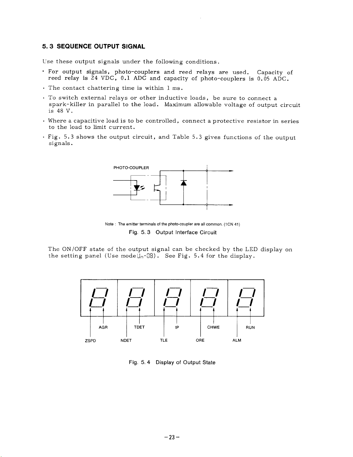
5.3 SEQUENCE OUTPUT SIGNAL
Use these output signals under the following conditions.
o For output signals, photo-couplers and reed relays are used.
reed reIay is
. The contact chattering time is within 1 ms.
. To switch external relays or other inductive loads, be sure to connect a
spark–killer in parallel to the load. Maximum allowable voltage of output circuit
is 48V.
. Where a capacitive load is to be controlled, connect a protective resistor in series
to the load to limit current.
, Fig.
5.3 shows the output circuit,
signals.
24 VDC, O.1 ADC and capacity of photo-couplers is 0.05 ADC.
and Table 5.3 gives functions of the output
PHOTO-COUPLER
Note : The emitter terminals of the photo-coupler are all common, (1CN 41)
Fig. 5.3 Output Interface Circuit
Capacity of
The ON /OFF state of the output signal can be checked by the LED display on
the setting panel (Use modeti~-~3) . See Fig.
l_l
l_J
AG R
1:1
l_l
TDET
1—1
1’1 1:1
1P
5.4 fox the display.
1—1
l_l
l_l
CHWE
RUN
Y
ZSPD
NDET
Fig. 5.4 Display of Output State
TLE ORE
ALM
–23–
Page 34

5.3 SEQUENCE OUTPUT SIGNAL (Cent’d)
Table 5.3 Functions of Sequence Output Signals
Signal
Zero
Speed
Speed
Coinci-
dence
m
Zonnector
No.
lCIN
lCN
Contact and
Pin No.
Z SPD
-45
r“
~ 46
33
6
L 41
34
!!
41
Function
When the motor speed drops below the set level
(30 r/rein) , -1 close. Once _ is
closed, it continues closed for 50 ms.
w(x),,,
Since -D] is output irrespective of l-]
and ~~, it can be used as a safety run inter–
lock signal.
For j Z SPD ~signal, photo-coupler output and
contact output are used.
When the motor speed enters the preset range of
~, = closes, However$ in baseblock
status ,
it remains closed for50 ms.
When this signal is used as an answer to S command
in NC program operation, the program is advanced
to the next step.
Speed coincidence signal
setting range of flO% to
f50% of rated speed is
selected with speed ;;;!ikJ~ o
coincidence range
constants (’~n- 3’2) .
it is not outputted. Once -I is closed,
SPDI CLO>E
.,!
REI; F-RSE k?
,,,,,,.,
n
FC’RAARD ,,, ,,,
.,,0,, Example (or
(),X,
..pc. d Co,, )c,d,r)w .S,x,lal
~~(
np~’”
-bU,
Speed
Detection
~
Torque
Detectior
m
Torque
Limit
m
lCN
lCN
36
{
f!!
41
37
When the motor speed drops below a
m closes.
The speed detection level is set
between O and 100% speed with
the preset constants ([~, - lb ND ETL) .
Hysteresis width is set in [~---] .
-] operates regardless of the run direction
signals .
-] can be used as the detection signal for
the speed suitable for clutch actuation or gear
shifting.
When torque decreases below a specified level,
m closes.
The torque detection level can be set between 5
and 120% of 30–minute rating with the control
constants (1,-, !S
m]
torque limit function, and for determing the load
conditions.
—
When external torque limit ‘~] or ~] is input,
~, will be closed.
. ~ can be used as check signal for ~1 and
EzzE1.
can be used as a signal for checking the
TDET) .
preset level,
—
N
41
-24-
Page 35

Table 5.3 Functions of Sequence Output Signals (Cent’d)
a=::z
Signal
Alarm
~AIM
Spindle On{
Flotation
Signal
[m
.Alarm
Code
[m
[Kizz
[m
[AC 8’
Connector
No.
1CN
1CN
1 CN
~ontact anc
Pin No.
ALARM
M 42
c
, -a, I . This signal is only for the unit with magnetic type
i--+
AC1
a
AC2
@
AC4
“ When protective circuit for overcurrent or overload
43
tripped, the motor current is instantly interrupted,
and the motor stops after running by inertia. Upon
current interruption. [ALLr is output.
44
“ The m relay is normallyopen mode. The contact
is “C” type.
. While ~] is output, the motor cannot run.
o When ~] is used to reset -1, ml or
WI, displays a spindle alarm visual signal.
“ l=] is displayed on the setting panel. For these,
refer to the alarm code shown below.
. For the relationship between l-l and ml,
refer to Item “Alarm Reset” in Table 5.1.
--
orientation card (JPAC-C 345 and FS-1378 type).
“ During the ml input, l_~ is closed by sensor signal.
. The signal may not be output at a spindle speed of
300 r/rein or above.
. The contents of the alarm is output by the alarm
23
code signal.
. The contents of the alarm codes are as below
24
==
26
_Eh’lGSTP Emergency stop error ~
Function
AC8
8
I
27
25
THLISTA Thermo detectorchsconnecmn
DCFU L>Cch-cultfuse blo\vn
ISO AMP Isolation amplifler defectl\,e
16 ~~
17 PLE
18 K!a
19 ;EH /
20 IERE
21
IE’R,7
@
w-’’ ----- Y: ‘r?
CPL”-AI) CPU AD defecti\e
~di=o..~.ti(,n
ROM PROM error 00 1 0
RAW1 Internal ItAM error
RAN1-E Ext;rnal RAM error
~tAM error
CHE Wlndirli?select,onerror
&xcessivc s~ced devlatlon
PGC PG
: =aI
Controller fumuon de femve
counter de fectl~,e
L
In addition, there is an orientation completion signal as a sequence output signal.
For details, See “IMagnetic Sensor Type Spindle Orientation” on page 83.
-25-
0001
Page 36

5.4 OPTICAL ENCODER (PG) PULSE OUTPUT CIRCUIT
[ PCA, * PCA, PCB, * PCB, PCC, * PCC] * Reverse signals
Phases A, B , and C (original point) signals for the optical encoder, PG( 1024
pulses /rev) are output.
Use these signals as the positioning signals.
are as follows:
( 1) Signal form
Two-phase pulse with 90° pulse difference (phase A and B)
I Original point pulse (phase C)
(2) Output circuit and receiver circuit
Line driver output is provided as output circuit. Fig. 5.5 shows the connecting
example of output circuit and receiver circuit.
The output signal specifications
(3) Output phase
~: Twisted-pair lead
Fig. 5.5 Output Circuit and Receiver Circuit
FORWARD RUN
(c)
REVERSE RUN
Fig, 5.6 Output Phase
-26-
Page 37

5.5
ANALOG OUTPUT SIGNAL
~lse
the analog output signals in the following conditions,
Table 5.4 Function of Analog Output Signal
Signal
Speed-
ometer
m
Connector
No.
lCN
or Screw
Terminal
No.1
Pin No,
47
Function
When an external speedometer is connected, the
motor speed can be monitored.
Speedometer signal terminal outputs DC voltage
signal proportional to the motor speed, regardless
of the run direction.
Select a voltmeter as a speedometer which satisfies
the following specifications.
—
Item
Speedometer
Activation
Rating
Internal Resistance
Class
. The level of speedometer signal is adjustable with
the control constant ( L.- W
Since m is only for adjusting the speedometer,
the actual speed is not influenced by it.
. The forward and reverse run speed accuracy is
i2% max. of the rated speed.
Specifications
~701tmetey.
Moving coil type
10 V full-scale
10 kn
2.5 class or above
-).
Load
Meter
Signal
zz!l
S~te: For the meter OV, use pin Nos. 48
lCN or
Screw
Terminal
No. 2
50
. The load meter indicates the percentage of the
actual load to the rated output of the motor.
. Select a load meter conforming to the same specifica-
tions as the speedometer.
Load meter signal can be adjusted with the control
constants ([~- fll LMA~ and
md 49 of lCN or screw terminal No. 3.
c-
C’n– X
pi!xq).
–27–
Page 38

6. DIMENSIONS AND INSTALLATION
.--R _
— —- ———.
6.1 AC SPINDLE MOTOR DIMENSIONS in mm (in inches)
● FOOT-MOUNTED TYPE
,j’; lE
4-#z.
MTG HOLES) ~
Ei,
— .
k –– –—
QK
FOOT-MOUNTED TYPE
RatedOutPul!V
-8 5
~: +
—.
!F F XB
~–—N -_
Detail of Shaft Extension
., .4 +
%
\ 3-M5 DIA
“4
100394 DEEP
TAPPED HOLES
—s–1
(~:~:;%:HD )
I
I
B
.:
“?!3
d 100394 DEEP
.-
s
—.=
(37/22kW)
I
f
2-M6 DIA,
TAPPED HOLES
I
● FLANGE-MOUNTED TYPE
i
.
J
LB
—— +
KL
4-9Z
MTG HOLES
—.—=
Shaft Extension
Standard
ii,
, 15.minute rating
I?.91g6Y ?.09 {12.20 ~-
(i;,
I
(50?0 ED) /continuous rat(ng. Not fumshed with eyebolts for 3 7’2 2 <W u!vt
FLANGE-MOUNTED TYPE
lRatedOutnut!!I
I
Shaft Extension
-28-
Page 39

6.2 VS-626MTIII CONTROLLER
DIMENSIONS in mm (in inches)
● TOTAILLY-ENCLOSED TYPE
< m. x. w.
,CN
~Ali
0?3:5 0335
301 lWOVE
,X
8i&
‘!=
2
UI
n
o
cc
0
o
COOLINGFAN
MAINCIRCUIT
TERMINALS
:0118 OR ABOVE
~~
LOAD METEF{
TERMINALS M4
CO NTRCIL
CIRCUIT
CONNECTOR
MAIN CIRCUIT c. ~W u
“RM’NALS “ @ E “““ n ~&MB
{La.
<’
‘.
*
\\
.
X
‘(M) ~’ : ,ERMINAL,M4
L
L~m
‘G
EXHAUSTED
AIR
COOLING
AIR
....
MB
4MA
MTG HOLES
Panel Drilling Plan
........ ... ... ... ..------ -. ...!
● OPEN CHASSIS TYPE
LOAD
TERM
c
c
c
-.
(<’-w
‘Totally-enclosed panel mounting available
OLES
Ku
0>
~g
m<
Uu
0>
.0
mm
U-J-f
Model
ClMR-MT03-
3.7K
5.5K
7.5K
llK
15K
lB.5K
22K
30K
Construction
TcdaOy-
enclosed
Open
chaaais
Totallyenclosed (0!291 {1$5:1) 0;4:2)
Open
chassis
TotaOy-
enclosad
Open
chassis
Totally-
enclosed
Open
chassm
TotaO y-
enclosed
Open
chass[s
Totally
enclosed
Open
chaasia
w H
250
[9.84) (18.501 ,1;8:., (7.87) [17.91) (9.88) (7.56) (8.03;1 (3 a-j ~:p54)
300 (23.62) ,l;yz)
(11.81;I
(25.20) ~;::zl
300 850
(11.81) [33,46) ,1;9:7, (9.84) (32.68) (12.20) (8,98) (8,15)
420
(33.46) (12.871
(16,54) ,3:0:3) ,l::& (14,96] !3;::5 , (16,14) (g,lj) :8.$32)
D WI HI A
268
{10.55)
270
470
(10.63)
289
(11.38)
288
600
[11.34!
640
;1::;4) (9.84)
292
(11 .50!
850
327
200 455 251
580
250 (22,83) 300
620
(11.81)
(24.41)
250 830
830
380
(32.68}
310
410
B c
192 204
228
[8.98)
228 207
240 224
207
18 15]
E G I J K
70 to 75
(2.76 t02.95)
85
to 90
(3.35 t03.54)
(38:5 [: &,
90 to 95
(3.54103.74)
to 110 25
105
to 4.33)
(4.13
(0::9) (1$%) 11;4:2) (9%41) (7%
[02!9) 12;!:3) [2;%5) (1??8) (9% )
[o~;g)
(2:2:1)
[02;9) [3:3:8) [3;!:9) (1;?8) (9% )
—
830
(0.98) (32.68) (31.50) (15.75) [14.96)
—
[2:0:2)
—.
800
(9% ) (7% )
(l;~8)
[:,5:)
400 380
N MA MB
M6
M5
M8 M8
M8 M8
–29-
Page 40

6.3 INSTALLATION
6. 3.1 Installing Spindle AC Motor
( 1) Location
o See that air flow through the cooling fan is completely free from obstruction.
Maintain a minimum of 100 mm from the near of motor.
. See that the motor is free from direct splashing of cutting oil from the
machine tool.
s Mounting base , bed or frame must be solid and rigid enough to sustain the
motor or its dynamic load during operation so as to minimize vibration.
(2) Mounting
The spindle motor permits mountings at any angle from horizontal to drive-
end–down.
(3) Connection with machine
. For V-belt drive,
each other,
. For a gear drive, install the motor with the shaft paralleled with the machine
spindle, and the gear meshing centrally .
. Since AC spindle motor is rotated at a high-speed, even a small imbalance will
cause vibration.
ness 1/2 the key size indicated in the dimension drawing (shaft) . Special care
must be taken of the gear, pulley, etc.
and align the sheaves.
the shafts of the motor and driven machine are parallel to
The rotor is dynamically balanced with half-keys with a thick-
when designing machine tools.
6. 3.2 Installing Controller
To install the VS-626 MTIU controller in a power control panel or the like, take
the following into consideration.
( 1) Heat dissipation
. Incorporate heat dissipating features into the design, in due consideration of
the heat generating rate.
. For the heat generation rates of the different types , refer to Table 1.1,
Standard Specifications .
“ Maintain the operating temperature of the controller between O to + 55° C .
“ To maintain the cooling performance of the controllers, be sure to secure at
least 100 mm above (discharge side) and 50 mm below (suction side) spaces
the controller respectively.
(2) Maintenance
s In designing the panel housing , take the convenience of maintenance work
into consideration.
panel.
c For mounting and replacing the controller,
the right and left sides between controller and the side walls .
. The 1/0 terminals and the control signal connectors are located at the lowermost
part of the controller.
can be easily connected to the terminals and connectors .
Fig. 6.1 shows the mounting space.
Be sure to allow sufficient space to fully open the front
secure at least 30 mm space on both
Be sure to allow space below the controller so that cables
-30-
Page 41

30
‘7.7&, ~
‘+’-
(a) Open Chassis Type (b) Totally-enclosed Type
Note
1 Be sure to provide the rear panel of the controller with a cooling ;Iir flow space.
2. The cooling air velocity must be 3 m/s in air duct.
3. Insert packings under the units when installing them to avoid clearance,
Dimensions m mm (In Inches)
Type
CIMR-MTIIL
3.7 K,
5.5 K
7.5 K
lIK
15K
18.5K
22 K
30 K
Enclosure
Open chassis
Type
Totally-enclosed
Type
Open chassis
Type
Totally-enclosed
Type
Open chassis
Type
Totally-enclosed
Type
Open chassis 588
Type
Totally-enclosed
Type
Open chassis 755
Type
Totally-enclosed
Type
A~B
550
(21 .65)
550
(21 .s5)
600
(23.62)
600
(23.62)
786
(30.94)
I
535
(21 06)
~l~:o) ! ‘12 20)
k
555
(21 85)
470
(1850)
584
(22.99)
500
(19.69)
(23 15)
500
(1 9.69)
: (29.72)
650
(25 60) }
c
310
310
(1 2.20)
360
(14.17)
360
(1417)
480
(1 E90)
250
(9 84)
h
300
(11.81)
300
(11.81)
‘1=
420
(16 54) I
70 to 75
(2.76 to 2.95)
(335 to 3 54)
85 to 90
(335 to 3 54)
90 to 95
(3 54 to 3 74)
lo5tollo
(413 t0433)
–31-
Page 42

7. CONFIGURATION
7.1 CONSTRUCTION OF VS-626MTllI CONTROLLER
POWER TERMINALS
FOR COOLING FAN
SETTING
PANEL ~
CONTROL
CIRCUIT
BOARD \
COOLING FAN COVER
/
Fig. 7.1
CONNECTORS
(1CN TO 3CN)
Construction of VS-626MTIII Controller
Type CIMR-MTIII-11 K
-32-
Page 43

7.2 PRINTED CIRCUIT BOARD LAYOUT
GND
o
18F 1’?VF
NOUONJO:W
Pu
Pv Pw
~
o
L
r
1
h
o
k
ml
El
2
3
1CN
U 24 ~ [PROM)
U 23 ~ (PROM)
ANALOG COMMAND POWER SUPPLY
SELECTING CONNECTOR
m
c P2
PI
2CN
!
]Hl
ABC
m
3CN
I
4CN
(a) CIMR-MTJM Models -3,7K, -5.5K and -7.5K
Fig. 7.2 Controller Layout
Umu
3CN 4CN 5CN
lCN
2CN
;W
;,0P24
J0N15
,
Opl:
>*S
0
0
Hum”
6CN 7CN 8CN
o
I
(b) CIMR-MTIII Models
-IIK, and -15K
(c) CIMR-MT~ Models
-18.5K, and 22K
Fig. 7.3 Base Driver Layout
–33–
(d) CIMR-MTIII
Model-30K
Page 44

8. PREPARATION FOR OPERATION
8.1 CHECKS BEFORE TEST RUN
After completing mounting and connection of units , check for :
. Correct connections . Never use control circuit buzzer check.
o No loose screw terminals.
. Connectors are firmly connected to proper terminals, etc.
. No short-circuit conditions
. Operable condition of the motor, spindle anc[ machines ,
8.2 CHECKING POWER UNIT AND PRINTED CIRCUIT BOARDS
Check for appropriate types of the power unit and printed circuit boards in
accordance with Table 8.1.
met.
In this case,
contact your Yaskawa representative.
Table 8.1 Models of Power Unit and Printed Circuit Board
(Input /output terminals, fuses , parts in main circuits)
If the type is incorrect,
the specifications cannot be
Name
Power Unit*
Control Circuit
Board
Base Drive
Circuit Board
*Parenthesis shows motor capacity for 30-minute operation rating
3 7K 5.5K i
(37kVJ5HP’
; 155kW 75 HP)
JPAC-C342
JPAC-C341
‘(75”’OHp’’’k5:ie:ie
Model
CIMRMTII-[~:
JPAC-C343
JPAC-C371 JPAC-C372
8.3 CHECKING POTENTIOMETER SETTING
The potentiometers have been adjusted to appropriate level at the factory. The
potentiometers are paint-locked,
Be sure that the lock positions are not slided
from the paint.
8.4 CHECKING POWER SUPPLY VOLTAGE
Confirm that the input power supply voltage is within the allowable range shown in
Table 8.2.
Table 8.2 Allowable Range of Power Supply Voltage
Rated Voltage
Frequency
Allowable Range
=:’”
Note Spindle drive system can normally operate within a range of 170 to 253V
and has been set in such a manner that the optimum characteristics can be obtained
between 200 and 240V. Therefore, if the input voltage can be changed by switching
the transformer taps, operation with the most desirable characteristics can be obtained by setting the input voltage within the 200 to 240V range
-34-
::$
Page 45

8.5 CHECKING SPEED COMMAND INPUT SELECTION
Shunt connectors are selected by speed command input as shown in Table 8.3.
For analog command input, see Fig.
supply selector.
Table 8.3 Shunt Connector Selection
Speed Command Input
Vhen 2k0 potentiometer is
Ised,
2 kfl
lW
7.3 for the location of analog command power
Speed Command
—
—
Selection DAS
IICN
bP15
~ NCOM
#-GND
Analog Command Pow;
Supply Selector
P2 and C pins.
Select
!;;
;:,
u
@
c
P2
PI
G
—
PI
and C pins.
Analog
Command
when a potentiometer other
han 2M2 is used.
1
CN
10 mA MAX
12 VMAX
@
LP15
&-NCOM
#--GND
Select
Digital
Command
Nhen D/A converter is used.
1CN
DIA
CON-
VERTER
& NCOM
&GND
m
12-bit binary
3-digit BCD
2-digit
BCD
any of PI and C or
Select
P2 and C.
Closed
–35–
Page 46

8.6 FAULT DETECTION IN ISOLATION AMPLIFIER IN BASE DRIVE
Faults in the isolation amplifier in the base drive can be made with the control PCB,
.
base drive PCB and the new version PROM.
. Selection is made with the ABC selection
I
COnnf?CLOrS in the center of the control PCB
~: :,.
:,’
::
Selecting
A-B
How to select shunt connectors
The fault detec~ion function is available with only the
~’ersion base driver and the new version software used in
them are in the conventional version, selection must be made as shown below:
N’r-ong selection will result in Adc and FU alarms.
Y
‘\
;1
@
B
A
Base driver
Version
\\
\
\
Controller
Version
ETC
—c
-8570
-8570.1
-8571
(Base Type)
ETC
.8572
and subsequent
(Base Type)
‘\
Irrelevant
NSN
-151 and earlier
NSN
-1005 and earlier
NSN
-152 and subsequent
NSN
-1006 and subsequent
c
Selecting c
B-C
Capacity
3.7k-7.5k
‘~-~<~8&nt
llk-15k
18,5k-22k
30k
;;
@
B
A
new version controller, new
conjunction. When some of
ETC-8590
-8591
_ -8592
No selection
connector
A-B
Selection of B-C
results in Adc alarm
A-B
Selectionof B-C
results in
FU alarm
ETC-8593
and subsequent
ETC-8570
and subsequent
ETC-8880
and subsequent
No selection
connector
.A-B
Selection of B-C
results in Adc alarm
B-C
Selection of A-B
results in loss of
fault detection
Note : When the selection connectors are set to A-B, the ISO-AMP fault detection
functions are all lost.
-36-
Page 47

~). OPERATION ON THE SETTING PANE=
9.1 FUNCTIONS OF THE SETTING PANEL
The following operations can be performed on the setting panel.
LED display of control signal
Display of trace-back data
Display and setting of control constants
Display of malfunctions
9.2 LED DISPLAY AND OPERATION KEYS
The LED display and the operation keys are shown in Fig. 9.1.
mmlEIEl””-
–LED DISPLAY
ENIIHH H--
i I
I
F======F======
. “HOME”: Returns to home mode (data display of control signal
&,.!T I
Iu
I
-1
~
~ s Selects item number or data display
Fig. 9.1 LED Display and Operation Keys of the Setting Panel
U , ) when displaying an item.
[ . “SET”: Transfers displaying data to the control constant
. “MODE”. When displaying an item, another item can be selected
for subsequent display. (Display of control signal - Trace-back
display - Display of control constant)
. “ > “: Moves selected digit (flickering) when displaying a control
constant (value or number).
. Increases the numeral by 1 of the selected digit (flickering).
. Displays the next malfunction when displaying a malfunction
(if multiple malfunctions occur).
oDisplays the next data when displaying trace-back data.
I I
l—
ALARM RESET
–OPERATION KEYS
-31–
Page 48

9.3 KEY OPERATION AND LED DISPLAY (EXAMPLE OF OPERATION)
Operation of the functions described in par. 9.1 is as follo~vs :
9,3, 1 Home Mode Display (Immediately after Power ON)
, Data display of control signal
9. 3.2 Control Signal Display
. Display of the control signal item number
Depress ““’
L(.I
. Selection of control signal item U-I-~
Depress A
D.4TA
key.
key.
Llr, - U 1
•1
‘ Display of the contents
Depress ““ key .
o Return to display of the item number
Depress ‘“”
9. 3.3 Trace-back Display
o Display trace-back item number
Depress
Xote: Trace-back data display is performed by the
same operation as control signal data display
Dxr.i
E
4TA
~
❑
r———l
~ key.
key .
nIml
mElml
I
mEmzl
I
EImIIEl
I
Ii
n l_l ~
l_l
milml
_
I
n -1
. Control constant item display
Depress ~ key .
h{[):lb:
❑
9. 3.4 Display and Setting of Control Constants
. Display contents
Depress
“ Selection of f
changed
Depress p
(The selected
lh~j
~
M<)L)F
El
key.
he digit of the control constant to be
key twice.
digit blinks , )
-38-
EdlElll
Iz31mDl
DEdml
/l\
I
Page 49

“ Data change from 30.00 to 50.00
I
Depress A key twice.
❑
c Setting of the changed constant
?.lepress
* key.
❑
HOME
Depress —
“
•1
* When setting the data other than setting range
of constants,
. Depress
X
❑
key for 1.5 seconds
SET
all digits blink.
key.
SET
mmml
,Ii
I
mKImml:
/(\/l
, /,,/,,,,,
I
E15mIEl
Completed setting
\l/
DmmlIll
/,\
Impm
I
I
. Setting of the data other than setting range of
,-,,
1.!–, - ,_l , .
On this status be sure to display item.
Depress
‘~,,, key.
❑
9, 3.5 Return to the Home Mode
. Return to display of the item number.
Depress I‘~,~ key.
Home mode display
Depress the Y?YE key.
!Note: The return to the home mode can be accomplished
any time during item number display , provided there is no
failure.
—- -
—
SET/
r
I
EElml
E151mEl
EImImIl
mImml
I
I
–39-
Page 50

9.4 ALARM DISPLAY
Even if multiple malfunctions occur,
the order of occurrence are stored, for later information. The following is an
example of the sequence in case of a malfunction.
MALFUNCTION—
Data display of home mode (control signal l~r,-111)
-IOC display
.
Depress A
. FU display
n
I
key .
1
\
Oc
If a malfunction is detected,
it is automatically displayed.
a maxinum of four malfunctions as well as
— TIME
t
DCFU
=
1
s~ow~ ~~.~~
IS the first
malfunction.
I
EmIm
Depress A
c1
Note: Depress “& key when malfunction is displayed,
to select trace-back display .
during trace display to display the malfunction again.
key.
❑
Then , depress ~ key
m
u
i
Return to display of ‘-IOC ‘
-40-
Page 51

9.5 CONTROL SIGNALS
The actual contents of the control signals of par.
,,—-
,_,,–,-
of each bit.
,–,-,
I_:‘:(, !.1 i
LED
;, -
L, !7 - L(’,3
~:!-,-fl{ I MTEMP
[/!-,-~r~
~~!-,-fl~ I DODSP
and llfi are bit information.
Displag
I
I
I DIDSP
Code
TREF
Table 9.1 List
I
I
Torque command
Motor temperature
Internal state
Interface input state
Interface output state
Spindle speed
Name
Alarm state
Figs. -
of Control Signals
9, Z and 9.3 are the contents
9.1 are shown in Table 9.1.
Unit
rlmin
0/0
“c
Hexadecimal
Hexadecimal ~
Bit
Bit I See. Fig. 9.3
rlmin
Display at Power ON
I
n
,.,
,-,,–1
i
Motor temperature
~
Varies depending on –
internal state
See Fig. 9.2
I
I
1.[.1.11.1
n 11
l_l.l_l
n
1.1
rl
—
//!-,- /L~
Note: ~,.-fl /to -fl~ are trace-back data. Refer to Par. 9.3.3 “Trace-back Display”
FLUX
Magnetic flux command %
r I I I I I
—
Ikl! /_L I_/_
Fig. 9.2 Bit Display of DIDSP ~LI’rI-U71
WF@gR
ZSPD
III III” l—l- l—l-
- RDY EMG
L~~~ L~~c LR~T
LL
ORT
–LGR
NDET
/—/]
—1 —
I
.Fo R 1~-REv TLH
—MGR —DAS
;LE ALM
/—/”
1!
II
~Lc Hw ~PPl
,?l:,;-!
Fig. 9.3 Bit Display of DODSP (Un-fl@
-41-
Page 52

10. TEST RUN
Observe the following precautions before turning on the power:
* Check to be sure that there is no obstacle interrupting operations.
● Warn the personnel nearby before starting operation.
Turn on the power for VS-626MTIU after securing safety around the equipment.
10.1 CHECKING AFTER POWER ON
CAUTION
When the power is turned on,
begin to rotate.
Check the following :
10. 1.1 AC Spindle Motor
Check that the direction
direction of cooling air in
of cooling air is as shown in Fig. 10.1. If the reverse
Fig. 10.1 is required,
the cooling fans of VS-626MTIII controller and motor
contact your Yaskawa representative.
I
L
1-
I
1
(a) Flange-mounted Type
Fig. 10, 1 Flow of Cooling Air of AC Spindle Motor
10. 1.2
After turning on the power,
VS-626MTIU Controller
‘) IJ“ is
and “CHARGE” will light dimly (red) .
ready signal (RDY) are closed,
of any malfunction,
or in case the above normal display is not made, investigate in
ltCHARGE ‘t wi]]
accordance with par. 11.
(b) Foot-mounted
displayed on the LEDs of the setting panel,
Type
If the emergency stop signal (EMG) and the
light brightly (red) . But in case
–42–
Page 53

10.2 STATE DISPLAY
The states of the VS-626MTIII controller and the motor can be monitored by display-
ing the contents of ~-!n-~-lI to - !!.!.
motor speed ( l.;,-,-l_l1
- ) is displayed. Check
Immediately after turning on the power, the
that other state displays are as shown
in Table 9.1.
10.3 CONTROL CONSTANTS
Control constants are set at the factory
stant setting table.
Before turning power
that the constants which can be referred
before delivery according to the conON, check the setting panel to assure
to are the same as the initial settin~
value. If they do not correspond to the constants of the constant setting tabl~,
reset the constants using the setting panel. Refer to the constant setting
value list
(provided under separate cover) for the preset values other .
Table 10.1 Setting Range and Initial Setting Value of Constants
~o-No.
—
E9
::
/(
; ‘7
– ~~
/s
:7
:8
;s-..
?:
—.
_23
.Ls
~
26
.,?:
28
-< z
.A”----
3;
..2L_
..X
_ 33––. -
35
..35
3?
38
3s
Y:
,+:+
,,,p f
‘1’3 f
,=,,., f
,,
,,, q f
V!:T
.+
+!Zt
—
<<g+
..
* Lower-and-upper hmit of the constant depends on enhancing PROM.
t The maximum speed of the motor.
+ [,.,,+~ to qg do not exsist for the winding selection SYStem.
Code
TSFS
Soft
start tjme of speed reference
EMGTIM Emergency stop monitoring supervisory flmer
INORH Speed control I (H gear)
INORL
IORTH
IORTL
*
NDETL T-~eratlon level of speed detection signal
DNDTL ~ Hysterlsla wjdfh of speed detection signal
TDETL
SELCD 1
I SELCD 2
ACCTLI
DECTLI Torque Ilmlt lever (brake sfde)
D12LIM I 2 rate Iimlf
Speed control I (L gear)
Speed control I (H gear, ORT)
Speed control I (L gear, ORT)
Operation level of torque detection s[gnal
H-gear ratio (Spindle speed/Motor speed)
M-gear ratio (Spindle speed/Motor speed)
L-gear rat[o (Spindle speed/Motor speed)
SelectIon code 1 (operation condltlon)
Selection code 2 (operatjon condl
Torque Ijmlt level (motor side)
IwLVLL Magnetle flux lower level
IWGAIN
PHAIw E
PHAILM
] PHITAP
CP
NBTAP
1
I NORT Orlentat]on speed
N(
CRP Creep
[
I AGREE
>FFSFT I Analog speed reference offset adjustment
o. _-
SPD1 Sp
SPD2
SPD3
sPn4 Srwed settina 4
-.
1
SPD5
SPD6
SPD7
I sPrlt? ! Sneed settina 8 1 -E*
i
Magnetic flux compensation level
Magnetic flux level at orlentat!on
! Magnef[c flux upper level
~ Magnetic flux lower level of servo r
Base speed of servo mode
speed
Speed agreement s!gnal width
1
>eed setting 1
I Sn
.>eed setting 2
I
<nood <ottinn ? 73,=
-w--w -- ..,,,= -
I
,
Speed setting 5
Speed setting 6
Speed setting 7
Description
jde) 1.00
tlon) 0000
mode
Lower’ Upper-
Limit Limit
10000
100.00
~ 1 5600
=
.1===
100
---t
000
4---’
0000
-“–—r
..—5%
,.%~=
‘ ‘0’+
000
0.00
1000
—4
fo
1000 ms
1000 nls
10 I
o
1000 “/0
5
10000
FFFF
FFFF–
50
~=
50 __
:0 200 ms
15 100
25”50 %
60
. . . .
100.00 1
10000
Unit
1 50
1 10
350 “/0 —
ns
100
120
150
150
--———
100
120
100
-——
——
~, =---
rlmm
——
%
%
%
%
%
%
%
%
v
“/0
“/0
%
%
“/0
“/0
“/0
%
“/0
–43-
Page 54

10.3 CONTROL CONSTANTS (Cent’d)
--, --
*
Page 55

10.4 OPERATION
After checking with power on ,
supply a running signal to operate.
Gradually
increasing the speed reference from O% starts the motor. Check that the direction
c,f motor rotation is proper.
The proper direction is counterclockwise as viewed
from the motor shaft end when forward run signal (FORRN) is closed and the speed
reference has a positive polarity.
A wrong phase sequence of the power cable between VS-626MTIII controller
and motor or the PG signal can be considered if the direction of rotation is reverse,
cr if the motor creates excessive noise or vibrates,
cperation.
Turn off the power and check the wiring.
without rotating,
Check that the motor smoothly accelerates and decelerates in both forward
and reverse directions by changing the speed reference, At the same time, check
that the motor is not vibrating or emitting noise excessively. The sound of the
motor constantly audible at several thousand hertz is caused by the control system
and presents no problem.
during
Fig, 10.2 Direction of Motor Rotation
CAUTION
● Start the motor after confirming that the motor is completely stopped, If the
motor is started during coasting, overvoltage (OV) or overcurrent (OC) may occur.
● Do not turn on MCCB in the VS-626MTIJI controller after turning on the power.
Tripping may occur due to the charging current to capacitors.
(Power supply OFF + MCCB ON + Power supply ON)
-45-
Page 56

11. SETTING AND ADJUSTMENT
VS-626MTIII controller is preadjusted at the factory. Normally , readjustment is
not required.
depending on operation specifications .
11.1 SETTING
11.1, 1 Load Meter Full Scale Setting (LMFS ~!-,-fl~)
The load meter indicates the output ratio(%) with the maximum output of the motor
during operation.
in control constant
11 .1.2 External Torque Limit Level Setting (EXTLIM .Z,I-H3
This constant is used to operate the torque limit externally. It can be set in the
range of 5% to 150% of the 30–minute rating output.
11 .1.3 Soft Start Time Setting (TSFS . .E!I- Ifl)
The soft start time is the time required for an acceleration/deceleration command
to be reached from O r/rein to rated speed or from the rated speed to O r/rein.
The soft start time can be set in the range of O. 1 to 30.0 seconds. The command
and the time are related as follows.
However, the setting value shown in Table 10, 1 can be changed,
Write the load meter full scale value( % of continuous rating)
l.rj–o~ .
Fig. 11.1 Soft Start Time Setting
11 .1.4 Rated Speed Setting (N1OO .~!~-~ 0
Set the rated speed according to the specifications of the machine tool. ‘l’he motor
rotates at this rated speed when 100% is input as the speed command value.
The rated speed can be set in the range from 3500 r/rein up to maximum motor
speed.
–46–
Page 57

1”1, 1.5 Speed Detection Level (N DETL .r,~-1~)
The external output signal m] will be closed when the motor speed falls below
this setting value.
control signal 1.11-1-I.H
The LEDs on the setting panel will display the following when
is called up.
The speed detection level can be set in the range of O% to 100%.
Hysteresis width can be set to O to 10 % in ~-,- ~-!.
,–
, ,.,-:~:,
1 ‘1. 1, 6 Torque Detection Level Setting (TDETL .[,I-IH)
This signal is used to set the operation level of the torque detection signal =]
(L- closes when torque decreases below a specified level) . Whenl~lis closed,
the LEDs on the setting panel will display the following when control signal
II
-08 is called up.
ur,
The torque detection level can be set in the range of 5% to
150% of the 30-minute rating output.
-
TDET ON
11.1, 7 Speed Coincidence Range Setting (AGREE . .E,n-lq)
T his signal is used to set the operating range of the speed coincidence signal [~G~]
(~~] closes when speed coincides. )
The speed coincidence range can be set
in the range of 10% to 50%.
50 ----------------
1-
0.12
~
1.2
OPERATING I
0
SPEED REFERENCE (%)
SPEED
DEVIATION
( % )
Fig. 11.2 Speed Coincidence Range Setting
x
1
1
1
Note Speed deviation is
100
expressed as a percentage
of 100 “A speed reference.
–47-
Page 58

11 .1.8 Gear Ratio Setting
H-gear . . . E,-,-22
M-gear . . . [,-, -?S
L-gear . . . [!-, -?’-/
The gear ratio should be set to suit gear ratio (or pulley ratio) which is determined
according to the specifications of the machine tool. The spindle speed is operated
and displayed by this constant.
This gear ratio is also used as constants at orientation operation.
The gear ratio can be set
H-gear . . .
kl-gear
L-gear . . .
0.050 to 1.500
0,050 to 1.500
. . .
0,050 to 1.500
H-gear, M-gear, or L-gear is selected by the external signal as shown in the
following table.
1.
Gear Selection
H-gear OFF ~
M-gear ON OFF
L-gear
11.2 ADJUSTMENT
11, 2.1 Adjustment of
Readjust as follows ,
speed (motor speed) is required.
Motor Speed (NADJ .~,~-f15)
when a fine adjustment of the absolute value of the spindle
n the follo~ving range:
Gear ~-atio = Spindle speed
[
NOTE
External Signal
M-gear L-gear
OFF ON
I
Motor speed
OFF
)
1.
Rotate the motor in the forward direction, measure the speed reference voltage
with a voltmeter and set it to the reference voltage of the desired speed.
2.
Measure the speed with a speedometer after the reference voltage is adjusted.
3.
Set the NADJ value larger than the current value if the speed does not reach
the desired speed.
4.
Set the NADJ value smaller than the current value if the speed exceeds the
Adjust NADJ until the desired speed is obtained.
desired speed.
NOTE
If there is no speedometer available, the speed can also be set using the setting panel
(~fn-fl i). In that case, the speed cannot be monitored while setting the NADJ,
–48-
Page 59

1“1 2.2 Adjustment of Speedometer (SMADJ ., .F,-,-CA)
For fine adjustments of the speedometer,
a.:
the rated speed at the factory , Adjust as follows, if the output deviates ,
1.
Set the speed command at the rated speed.
2.
When the speedometer shows a lower value than the rated speed, set the SMAD. J
value larger than the current value,
When it shows a higher value than the rated speed, set the SMADJ value
3.
smaller than the current value,
2.3 Adjustment of Load Meter (LMADJ .E,z-0’7)
1 “1.
so that it indicates the rated speed.
For fine adjustments of the load meter,
output the voltage shown in Table 11.1 at 120% of 30–minute rating ,
follows ,
1. Display the constant L ,-,- 0“!
2. Depress
if the output deviates.
(for adjusting load meter ) on the setting panel.
H and M ‘eys ‘imu’taneous’y
the potentiometer is set to outputl OV
so that it indicates the rated speed,
the LMADJ is preset at the factory to
Adjust as
Then the voltage equivalent to 120% output of 30-minute rating is output from
load meter output ( lCN or screw terminal @ ) .
3. If the load meter indicator indictes a larger value than the % setting value of
Table 11.1, set the LMADJ smaller than the current value, so that it becomes
the prescribed %.
4, If it is smaller than the % setting value, adjust the LMADJ to a larger value
so that it becomes the prescribed %.
5. Change the display of load meter adjustment
(LMADJ. . :,-,-/;’1 ) to another
display on the setting panel. Then the load meter outputs the regular value.
30-mmute
RatmglContmuous
Rating kW (HP)
3.7/2.2 (5/3)
5.5/3.7 (7.5/5)
7.5/5.5 (1 0/75)
11/7.5 (15/10)
15/11 (20/15)
18 5/15 (25/20)
22/1 8.5 (30/25)
30/22 (40/30)
*Cannot be set
Note % In [
Load Meter
FuII Scale
1ISmeter indlcat!on
Table 11.1 Load Meter Output Voltage on
30-minute Rating at 120% Output
i’oyo
1
Load Meter Load Meter
output v
I
I
I
*
*
9 6/ [163%] 90 [1 62%] 81 [162%]
*
9.6/ [163%]
8.7/ [148%] 82 [148%]
[143°/0]
8 4/
I
I
I
9.6/ [163~o]
180%
output v
*
100 [180%1
——4---
98 [177%] ~ 88 [1 76%]
90 [162%1
-------*
79 [1 42%]
9,0 [162%1
I
=’
I
I
I
100 [200%1
90 [180%1
71 [142%]
81 [162%]
–49–
Page 60

11 .2.4 Adjustment of Loop Gain of Speed Control System ([!-I-O / to -C’-;)
I?NORH . . .
PNORL . . .
PORTH . . .
PORTL . . .
PTAP
. . . Solid tap speed gain
Speed gain (H-gear)
Speed gain (L-gear)
Orientation speed gain (H-gear)
Orientation speed gain (L-gear)
Lt-,-i; /
L-o - L(2
--
L I-I- LI:(
L1-I- i: ‘+
[.- ;g
This is used for adjustment of loop gain of speed control system. The five constants listed above can be adjusted respectively, depending on the operation mode.
The closer the setting is brought to O,
but the response becomes slower.
the lower and more stable the gain becomes,
The larger the setting is adjusted, the quicker
becomes the response, but the control system tends to become unstable. Adjust
it to the optimum gain , taking into consideration the load conditions .
Adjusting range of the constants is as follows :
“Speed gain(H-gear )....... . . . . . . . Itoloo
.Speedgain(L-gear) . . . . . . . . . . . . . . Itoloo
“ Orientation speed gain(H-gear) . . . . I to 100
. Orientation speed gain(L-gear) . . . . I to 100
.Solidtap speed gain..... . . . . . . . . . lto 100
NOTE
Loop gain of speed control drives changes depending on rated speed settings
(N 100- Cn 21). It is determined through speed setting rat[o for motor
maximum speed.
Internal
Speed Gain = Speed Gain Set Point X
5.5 kw motor standard type (maximum speed 8000 rim in)
ex. )
/_-,-,—,:-1,,
Internal Speed Gain = 30 X ~
Gain has no change.
(:,.,-,-l 1 ‘- n<, E’-;, i5)
,-, ,, /_/,:’,
setting “-
8000 r/rein ~J-i-~ i setting . ..30
()
Motor Maximum Speed
Rated Speed Setting ~,-,-,~1 )
(
2
= 30
2
kW motor standard type (maximum speed 8000 r/rein)
5.5
ex. )
,:-,.,- ,_:,:
Internal Speed Gain = 30 X ~~
Very high gain and not stabilized.
If internal speed gain is standard at approx. 30,
,#_-,_,—,,_,f,1
–:5 are the same.
setting 6 shall be approx,
Maximum speed of standard type motors is
Motor
Capacity
~~~~~um (r/rein)
setting ...3500 r/rein EI-,–flf setting . ..30
()
WJ 2.6
30+
3500 =
()
30 and be stable. ~J-t-flI~, ~~<, ~~’-i,
shown In the table below.
(kW) 3 7/22 5.5/3 7
==l=T== 6000 600”
7“’5’7’7
2
-50-
+157
c“
~ 5000 4500
Page 61

12. VS-626MTm CHECK TERMINALS AND THEIR SIGNALS
Table 12.1 VS-626MTJJI Check Terminals and Their Signals
Check
Terminal
Signal
Description
Note
Control
Circuit
Board
FCT
PWM carrier signal
‘*’
r
VR
Iu
Iw
IUF Phase U current
IWF
Pu
NU
Pv
NV
Pw
NW
GND Signal ground Ov
Current reference
I
~ Phase U
current reference
Phase W
current reference
Phase W current
PWM signals
,=,
12V et!
‘e
“m
T = 300ps f
Tp= 20 to 30ys
“8=F
Vp=6V+0,5V
T = 300/us * :30/s
V becomes large under load
and small under no load.
IW is led at forward run.
IU is led at reverse run.
IWF is led at forward run
IUF is led at reverse run,
30/uS
—
Check at
motor stop
OVat
motor stop
OVat
motor slop
OVat
motor stop
.-
Example of
low speed
operation
Vc
PI 5
Base
Drive
Circuit
Board
I The check terminals allow oscilloscope connection for measurement.
:2. During measurement, do not short the adjacent two check terminals,
as the connected elements may be destroyed.
3 IUF, IWF current conversion ratio is shown in the table below.
Inverter
Capacity
Current
Conversion Ratio
N15
P25
P24
“---1
GND I Ov
~5v
+15V
I
I
–15V
i
+25V
L24V
Signal ground
3.7kW 5.5kW 7.5kw llkW
6V/1 00A
~
15kW 18.5kW 22 kW
6V/200A
I
6V/300A
–51-
+5V +0,25V
t15v2co,15v
15 V*0.15V
+25 VZ2V
+24 V+2V
30 kW
6V/400A
I
I
I
Page 62

13. MAINTENANCE
VS-626MTTU requires very few routine checks , but regular periodical maintenance
is necessary to maintain normal and smooth operating conditions.
maintenance schedule after studying the maintenance items shown below.
CAUTION
Do not touch the inside components of VS-626MTIII for 5 minutes after turning
off the power supply. Before servicing inspection, check that the smoothing capacitors
lamp being off.
have been completely discharged. This can be verified by the “CHARGE”
13.1 DAILY INSPECTION ITEMS
For the spindle motor, daily inspection of the following items shoud be performed:
, Rated speed is correct.
. Cooling fan rotates smoothly.
o Cooling air circulates normally.
. No abnormal vibration
s No abnormal sound
Formulate a
. No abnormal odor
VS-626MTIU controller requires almost no routine checks since it has been designed with highly reliable circuit technology and is comprised mostly of semicon–
ductors,
such as ICS and power transistors .
13.2 PERIODIC CLEANING
The VS-626MTIII controller must be cleaned periodically as follows .
, If the controller has air filters , these must be cleaned once” a month.
o Dust and dirt on the electric parts w-ill deteriorate the insulation or cause over-
heat.
regenerative resistor and the heat sink at the rear of the controller will also
deteriorate and cause malfunctions if coated with dust.
6 months with an air blower or wiping \vith a dry cloth. Clean them more often
if conditions require .
These must also be cleaned periodically.
The radiating efficiency of the
Clean these once every
–52–
Page 63

13.3 PERIODIC INSPECTION
T’o maintain the AC spindle motor and VS-626MTIlI controller in
order, perform periodical inspection and maintenance referring
Table 13.1 Periodic Inspection Items and Description
Check
Replace cooling fan,
Contact Yaskawa representative,
—
Clean approximately once every 6
months or more frequently, depending on operation conditions,
Coating of dust or oil in air passage may decrease cooling effi-
ciency and cause malfunctions.
—
Tighten.
Replace coolind fan.
AC Spindle
Motor
Item
Cooling Fan
Motor Bearing
Cooling Air,
Inlet Port,
Exhaust Port,
Air Passage
External Terminals,
Unit Mtg Bolts,
Connectors, etc.
I Cooling Fan
● Abnormal sound or vibration.
● Cumulative operating time
exceeds 20,000 hours.
● Abnormal sound
● High temperature
● Coating of dust or oil
Loosened screws / bolts
● Abnormal sound or vibration.
● Cumulative operating time
exceeds 20,000 hours.
good operating
to Table 13.1.
Corrective Action
VS-626MTlll
Controller
Printed Circuit
Board
Smoothing
Capacitor
Air Filter
(Control panel)
Electronic Parts
Regenerative
Resistors, Heat
Sink (on the Rear
of VS-626MTIII
Controller)
Discoloration–brown color
I
Discoloration or unusual odor
Coating of dust
Coating of dust
Coating of dust
Replace the board.
Replace the capacitor or inverter
unit, as necessary.
Clean once a moth.
Remove dust periodically.
Remove dust with air blower or a
dry cloth once every 6 months or
more frequently, depending on op-
eration conditions. Dust accumw
Iated on regenerative resistors or
heat sink may decrease radiating
efficiency and cause malfunctions,
–53–
Page 64

13.3, 1 Prolonged Storage
If VS-626MTIII controller is installed as a standby unit, or is kept out of operation
for a long period of time, check its operation at least once every six months by
turning on the power supply.
Reformation is necessary for electrolytic capacitors if they have not been used
for a long time (more than 1 year) .
Reformation can be accomplished in the
following way:
1, Turn off the Ready signal, then turn on the power. “CH.ARGE “ lamp (red)
lights dimly.
2. After 5 minutes ,
turn on the Ready signal.
“CHARGE “ lamp (red) lights brightly.
3. Let the controller stand for 30 minutes .
13.4 CHECKING SEMICONDUCTOR ELEMENTS
FOR MAIN CIRCUIT
When checking semiconductor elements for main circuit, remove the base drive
circuit board (See par. 13.5) .
When remounting the base drive circuit board,
connect the connector leads to the specified connector terminals and screws cor–
rectly and tighten them firmly. If only one screw is loose, or missing the VS–
626MT~ system will not operate properly.
13.4, 1 Transistor Module
Checking Method
Measure the resistance value at the terminals shown in Tables 13.2, 13.3 and 13.4,
with an ohmmeter.
Power Transistor Module for Main Circuit
Abnormal
Resistance Resistance
cm
Several
n to
approximate
multiple
of
10Q
OQ
00
or
cc
Transistor Module
Check the terminals on
the power circuit board.
Terminals
@
VS-626MTllI
Controller Model
CIMR-MTIII-
37K
5.5K
7.5K
Table 13.2 Resistance of
ohmmeter Ohmmeter Reference
Terminal Termmal
E
P
~;.
—:4:
F
v P
~.
‘vV
1.
N’V
[+-:
u
v
r
w
u
w
c,
lIK
15K
18.5K ~ –—
E1, CZ E2
E,, C2
~~~ *~mu,tipleo,
E< E,, C2
Note Use the ohmmeter set at x 1<) range.
cc
Several 0 to
approximate
100
-54-
on
0.0
0.3
; cl
+
EI C2
a
or
%
E2
Check the
transistor
module
terminals
Page 65

Table 13.3
Resistance of Power Transistor Module for Regenerative Circuit
VS-626MTHI
Controller Model
CIMR-MTUI-
3 7K
55K
7.5K
IIK
15K
185K
22K
30K
Note Use the ohmmeter set at X 1Q range
Ohmmeter
Terminal
c,
K,
E,
c,
c<
E,
E,
A,
c,
E,,
c,
El
~z
E,
E,
c,
-l”
c,
K,
+
E,
A,
c1
E,
E,,
c,
E,
+
El,
C2
ti
I
I
I
I
w
02
to approximate I
multlple
of 1OQ
on
00,
Power Transistor Module for
Regenerative Circuit
2 TRM (7 5K or below) 3 TRM (7 5K or below)
4TRM (11 to 15K) 5TRM (11 to 15K)
Check the terminals on
[he
power clrcult board
c,
E,, C2
i ‘E,
or
m
Check the termtnals of transistor module
@
1:3. 4.2
Checking Method
Measure the resistance value at the terminals shown in Table 13.4.
Controller Model
Note Use the ohmmeter set at X 1Cl range
Thyristor Module
VS-626MTIII
CIMR-MTIIL
185K
22 K
30 K
Table 13.4 Resistance of Diode Module
Tester Terminal
DIODE MODULE TERMINAL
1
u
1
c#-+@-t-@
@
x
•1
Reference
Resistance
3
o ~Less than
Approxlrnate
rnultlple
Ion
of
Abnormal
Resistance
Less than
Approximate
multlple
of 100
–55-
Page 66

13. 4.3 Diode Module
Checking Method
Measure the resistance value the terminals shown in Table i3. 5.
Table 13.5 Resistance of Thyristor Module
Ohmmeter
Terminal
(3’
_—– —
P.
RO
-7
so
I
—- i I
I p. ‘
Ohmmeter
Terminal I Re~istanCe
‘z
.,
RO ~
so
Reference
cc
I
I
Approximate
multiple of
1 OQ or
below
Abnormal
resistance
\
Thyristor Module for
Regenerative Circuit
~- i
RO
—.—
No
Note’ Use the ohmmeter set at X IQ range
L—
L?’
10
I
I
Check the terminals on
the power circuit board.
I
13.5 REPLACEMENT OF PRINTED CIRCUIT BOARDS
If the printed circuit boards are replaced, see Table 15.1, contact Yaskawa
representative with parts name, parts code -No. and quantity.
CAUTION
Do not replace the printed circuit boards or remove the connectors when power
supply is ON since the parts of the circuit may be damaged.
13. 5.1 Replacement of Control Circuit Board
(1) Removal Procedures (Fig. 13. 1)
1. Turn off the power supply and disconnect the connectors ( lCX to 3CN , lFC,
2FC) and the ground lead from the control circuit board (PCB ) .
2, Remove the five PCB mounting screws (M4) .
the
3. Hold each head of
supports from the
PCB supports with round-nose pliers and remove the
guide holes in the PCB (Fig. 13. 2) .
-56-
Page 67

RIBBON CABLE
MTG HOLE (5 HOLES)
/
0’
0
MRCONNEC1”OR .
*%
/’
-.;~
;J#
GROUND LEAD
Fig. 13.1 Removal of Control Circuit Board
+NSERTION LEVEL
ROUND-NOSE
PLIERS
PCB
SUPPORT—
CONTROL=
CIRCUIT
BOARD
CHECKING SLOT OF
BOARD SUPPORT
CONTROLLER ‘
Fig. 13.2 Holding Head of PCB Support
with Round-nose Pliers
(2) Mounting
1. Insert the control circuit board in PCB supports until it comes fully to the
Procedures
Fig 13.3 Controller Mounting
checking groove in the supports, (See Fig . 13.3. )
2, Secure the PC13 to the PCB mounting board ~rith screws at five positions.
3. Connect the cables to the connectors.
4, Check the setting of the PCB and start operation.
-57-
Page 68

13. 5.2 Replacement of Base Drive Board
The board is mounted at tne rear side of the PCB mounting board.
(1) Removal Procedures (Fig. 13. 3) .
1, Turn off the power supply, open the control circuit PCB mounting board and
disconnect the connectors ( 1 to 12CN for 7. 5K and below, to 16CN for 11 to 22K,
1 to 18CN for 30K) , the ground lead and the power lead for cooling fan (u, v)
from the base drive board.
2. Remove the PCB mounting screws and three power connecting screws.
3. Hold each head of the PCB supports with round-nose pliers and remove the
supports from the guide holes in the PCB .
(2) Mounting Procedures
1. Insert the base drive board in PCB supports until it comes fully to the checking
groove in the supports .
2. Secure the PCB to the PCB mounting board with screws at four or nine positions.
3. Connect the cables to the connectors.
4. Check the setting of the PCB and start operation.
MOUNTINGSCREWHOLE
~15 HOLES)
Cf Bmu
,Fc ICN 2CN 3CN
Pgoobpl 5
VC P24 N15
I
0
o
gqy
POWERSUPPLYCONNECTIONSCREW
(3SCREWSI
(a)
3.7 to 7.5kW Base Driver
0
Q*.
Hi
al
,CONNECTOR
P TO12CNI
z
a
BOARD SUPPORT HOLE
( 3 HOLES)
m
L
:D
z
v
rl
Mot
JTINGSCREWHOLE
(9 H
.
w’
OG~ ‘o P25
U150 OP24
P350
0 Vc
r
i
lFC
o
o~omo
POWERSUPPLYCONNECTION
SCREW(3SCREWS)
(b) 11 to 15kW Base Driver
CONNECTOR
ED
50 ‘
al
:0
xl
m
m
Fig 13.4 Removing Base Driver
-58-
Page 69

I
3
17CN16CN 15CN 14CN13CN 12CN llCN 10CN 9CN
‘“---F-3
N
Page 70

14. TROUBLESHOOTING
If the VS-626MTIJI malfunctions ,
Table 14. 1,
Detection
(LED Display)
Overcurrent
(Iz;z)
If any other problem occurs ,
Condition when
err
a
a
.
n
—
o
o
o
find the cause and take corrective action following
contact your Yaska~va representative.
Table 14.1
Probable Cause
. Defective controller Contact Yaskav.a
. Main circuit
Connection error
o Load shorting
. Ground fault
. Defecti\e transistor
module
. Wrong setting of
control constants
Check Lklethod
representative.
Check the main
Circuit wiring.
Measure the re-
sistance bet~veen
motor terminals
and check ior
shorts .
Check the short
between output
terminals and
ground of the
controller.
Check the resist-
ance between
terminals of transistor module.
Ver]fy the control
constants by the
list of settings
for machines.
Corrective Action
. Replace the
controller.
. Correct the mai~l
circuit connection.
. Replace the motor.
, Correct grounding.
. Replace the
transistor module.
. Correct the control
constants.
!vICCB trips ,
(rjr~)
Regerierative
Overcurrent
. MCCB off
. Defective controller
o
o
0
o
o
o
. Defective thyristor
module or power
transistor module
for regenerative
circuit.
. Open phase in powe]
supply
. Defective thyristor
module or power
transistor module
for regenerative
circuit.
. Open phase in power
supply ;
uower failure
Check that MCCB
is off.
, Check that IvICCB
is on.
Check the resist-
ante of the mo–
dule.
. Check the voltage . Repair power supply
between input
terminals .
o Check the resist-
ance of the mod–
ule.
. Check the voltage
between input
terminals.
. Turn off the Dower
and turn on the
MCCB .
. Replace the control-
ler.
. Replace the module.
connections.
I
. Replace the module.
. Repair power
supply connections.
-60-
Page 71

Condition when
Detection
(LED Display
—
Regenerative
Overcurrent
((:, CC )
(Cent’d)
Overvoltage
(IZL.))
Probable Cause
. Wrong setting of
control constants
. Excessive braking
torque
o
o
0
. Defective controller
. High supply
voltage
I Low SUpply
voltage (due to
decrease of regen-
erative capacity by
decrease of supply
voltage)
Open phase in
power supply;
power failure.
Wrong setting of
control constants
Excessive braking
torque
Defective controller
Improper characte-
ristics of PG cable
Check Method
. Verify the control
constants by the
list of settin-gs for
machines.
. Contact Yaskawa
representative,
, Contact Yaskawa
representative.
. Check the voltage
between input
terminals,
. Contact Yaskawa
representative.
. Check the voltage
between input
terminals .
, Verify the control
constants b>- the
list of settings fo]
machines.
, Contact Yaskawa
representative .
Check the speci-
fications of PG
cable.
Corrective Action
Correct the control
constants.
. Reduce torque
limit level.
o Replace the
controller.
. Change the supply
voltage within the
specified range
by changing taps
of transformer.
Reduce the deceler-
ation torque limit
le~rel.
Repair power
supply connections .
Correct the control
constants.
Reduce torque limit
level.
Replace the
controller.
Replace the PG
cable (use Fujikura
Cable KQVV- SW) .
(n=,)
Ur. dervoltage
(Llu)
Wrong setting of
control constants.
0
c)
Defective controller
Large waveform
distortion of power
supply.
Open phase in
power supply;
power failure.
Verify the control
constants by the
list of settings
for machines .
Contact Yaskawa
representative.
Check the voltage
between input
terminals .
Correct the control
constants .Overspeed
Replace the controller
Repair power
supply confections ,
etc.
-61-
Page 72

14. TROUBLESHOOTING (Cent’d)
Table 14.1 (Cent’d)
Condition when
Problem Occurs
—
Detection
(LED Display)
Undervoltage
(Ufl)
(Cent’d)
Overload
(DL )
Excessive
Speed
Deviation
(dEu)
Motor
Overheat
(/2!%)
z
c
>
a
6
—
c
—
—
—
—
c
—
—
—
c
—
—
o00
0
0
o10
00
—
0
o 0
Probable Cause Check Method Corrective Action
Low supply voltage o Check the voltage
Defective base
drive or control
circuit board.
Motor overload
Frequent acceler-
ation /deceleration
OperatlOn.
Main circuit lead
broken , \\,rong
connection.
PG cable broken,
wrong connection.
Defective controller.
Motor overload
Torque limit oper-
ation.
0
, Wrong setting of
control constants
Main circu]t lead
broken , wrong
connection.
o
, PG cable broken,
wrong connection.
I Defective control-
ler.
, Motor o~,erload . Check the motor
. Motor cooling fan
stops.
0
between input
terminals.
. Contact Yaskaw-a
representative ,
, Check the load
w,ith load meter.
Check the connec-
tion between controller and motor.
Check the PG
cable.
Contact Yaskawa.
represent atil, e . ler.
Check the load
condition.
I Check if external
torque limit signals (TLL, TLH)
are input.
Verify the control
constants by the
list of settings
for machines ,
Check the connec- < Correct main cir -
tion between controller and motor.
o Check the PG
cable.
. Contact Yaskaua
representative.
temperature using
the setting panel.
—
. Check the opera-
tion of motor cOOling fan.
o Check for break-
ing of cooling fan
power lead.
. Change the supply
voltage within the
changing taps of
, Replace the base
drive or control
circuit board.
. Reduce the load.
. Reduce the fre-
operation.
. Correct main circuit
. Correct PG cable
. Replace the control-
. Reduce the load,
Release torque
. Correct the control
. Correct PG cable
. Replace the control-
Ier.
, Stop the operation
. Lighten the load.
. Replace the cooling
‘ Repair the cooling
specified range by
transformer.
quency of acceleration /deceleration
wiring.
wiring.
limit .
constants.
cuit wiring.
wiring ,
and cool the motor .
fan.
fan power lead.
–62-
Page 73

Condition when
Table 14.1 (Cent’d)
]Ietection
(LED Displ:
Motor
Overheat
(!5H)
(Cent’d)
Iv[otor Temp
a;ure Too L(
([3HL )
Controller
Overheat
([oH/= )
Flse
Disconnection
(/=~)
PG Signal
Fault
(fJL)
00
—
—
o
o
-
I
I
10 00 0
‘o
1
o
o
0
0’0
t-l
010
o 0
J
I
‘1
r
1
I
:,
Probable Cause
. Defective motor
cooling function
. Thermo detector
signal lead shortec
. Defective controlle~
Low motor temper
.
ature.
. Thermo detector
signal lead shortec
- Controller ambient
temperature high
.
Cooling fin dirty,
. Controller cooling
fan stops.
Fuse disconnection.
(Check
referring to overcur
rent col;mn)
Base drive fault
(See par. 8. 6)
PG cable -
disconnection
Main circuit
disconnection.
Base drive fault.
Defective control
circuit.
Defective controller
o
for the caus
Check Method
I corrective Action
;~erS*,~
nal lead.
Contact yolir . Replace the
Yaskawa represen
tative.
.
Check the motor . Raise the ambient
ambient temperature.
. Check the motor
temperature using
the setting
(ApProx. 14°C at
lead breaking. )
. Cheke the control-
ler ambient temperature. specified range,
. Check for coating
of dust, cut~ing oil, fin.
etc. on cooling fin.
. Check the opera-
tion of controller
cooling fan.
. Fuse disconnection
check
. Contact your
Yaskawa representative.
. Check wires of
PG cable.
, Check wiring –
between controller
and motor
. Check fuse in base
drive board.
. Turn off the pow-
er and after the
display on the setting panel i: off,
turn on the power
again
panel
controller.
temDerature to the
specified range.
. Repair the thermo
detector signal lead.
. Reduce the tenlper-
ature within the
. Clean the cooling
. Replace the cooling
fan or the controller.
. Replace fuse
. Replace base drive -
board.
. Correct PG wiring
. Correct the main ci-
rcuit wiring
. Replace base drive
board
. If normal, resume “–
operation.
. If a failure display
appears again, replace the controller,
Coil Change
Error (~ ~~ )
—
3 0;0 ‘C o
—
-+ —
10
k
II
00
Controller fault.
0
Coil change contac
tor fault.
0
–63–
. Contact
Yaskawa represen-
tative.
~ Contact you~Replace contactor.
Yaskawa representative. ~
your
. Replace controller.
Page 74

14. TROUBLESHOOTING (Cent’d)
Table 14.1 (Cent’d)
Condition when
Detection
(LED Display
I/fotor will
Etotate.
not
Motor does
not Rotate a
Reference
Speed.
10
L
Probable Cause ~
. Protective function . Check the cause
operates.
Control fuse blowm Check for blolrn
Torque limit oper:l-’ . Check if external
tion
—
Contr61 signals are
I
~
not input.
L
I. Defecti\e base
drive circuit boarc!.
. Incomplete adjust-
ment of speed.
. Torque ~imit oper:~-
L
tion.
signal error.
1
Wrong scttmg of-=fy the cor.trol “ Correct the control
k
control constants.
i
=
according to the
I,ED display on
I
I
F=-n=n””-
fuse.
torque limit signals !TLL, TLH)
I
are input.
. Check the control
signal using the
setting panel.
. Ready (RDY)
i
. Emergency stop
(EIVIG)
.
Forward (FOR J
or reverse (I+El’)
running.
. Sueed command
(fiR~F)
. Contact Yaskawa
representative.
. Check for speed
using the setting
panel.
. Check- if ext&al
torque limit sIg-
nals (TI,L, TLH) i
command {XREF) ~ command voltage.
using the setting
I
I panel.
constants by the
list of settings
I
1
corrective actions
. Replace the cont-
rol fuse.
. Release torque limit.
. Correct the control
constants.
. Replace the base
drive circuit.
: Adjust the speed
according to par
11.2.1.
. Release–torque limlt.
-–*
constants
–64–
Page 75

Detection
(LED Display
Condition when
Probler
~“
Table 14.1 (Cent’d)
Probable Cause
Check Method
Corrective Action
Acceleration
or Deceleration Time
T130 Long
Excessive
Motor
bration
\’]
or b’oise
J-
. Torque limit opera
tion.
I
I
. Setting time of
soft start too long
I
‘0!0
o
i
0
I
I
. Abnormal load
conditions.
. Wrong setting of
control constants.
Defective controller
Improper mount
ing of motor.
. Improper charac-
teristics of PG
cable.
. Motor or controlle]
not grounded.
‘lMain circuit lead
broken.
. Speed control gain
too high.
. Defective motor
bearing.
. Defective controller,
. Check if external
torque limit signals (TLL, TLH)
are input.
. Check for time of
soft start [ [n-10
using the setting
panel.
. Check for load
conditions ~ith
load meter,
. Check for loss and
GD 2 of load.
. Verify the control
constants by the
list of settings for
machines.
. Contact your
Yaskawa representative.
. Check for loose
screws, misalignment and imbalance.
. Check for foreign
matter, damage o
deformation of
moving parts of
machines.
. Check for the
specifications of
PG Cable.
. Perform condu6-
tive test of gro
unding,
. Check the connec-
between con-
tion
troller and motor.
. Contact your
Yaskawa representative,
. ‘Release torque limit.
. Change the setting
time.
‘Reduce the load, if
necessary.
o Correct the co;trol
constants.
. Replace the control-
ler.
. Correct.
(Tighten screws,
balance coupling,
etc. )
~Remove foreign
matter, repair or
replace damaged
parts.
Replace the P~
cable.
Correct grounding
cables, terminals,
etc. as necessary.
. Correct main cir-
cuit wiring.
. Reduce the speed
control gain using
the setting panel.
. Replace the motor.
. Replace the control-
ler,
–65-
Page 76

15. SPARE PARTS
Table 15.1 shows the number of pieces of
roller. At least one set of fuses should be
To order spare parts, refer to Yaskawa
the main parts used in a
stored.
Control Co., Ltd.
VS-626MT Ill cont-
T
Transis-
tor
Module
Diode Module
Fuse Circuit
Cooling Fan’
Base Driver
Fewer Board
* Only open chassis type
Main
Circuit
Regene-
rative
Circuit
Thyristor
Module
DC
I
k
Controller
—
Control
Cucult
Table 15. 1
Type
6DI-75-050 STROO0253
6DI-1OO-O5O
2DI-150-050
2DI-200-050 STROO0266
E\’L31-055 STROO0143
~M50E, Y-HD STROO0304 1 ‘- 1
JM50E, Y-HD
-
!M1ooE, Y-HD
!M150E, Y-HD
!M150E, Y-HD
EVK71-050 STROO~142
TM90DZ-H
Code No.
STROO0254
STROO0260
STROO0305
STROO0309
STROOO31O
STROO0311
SCROO0198 ~
I
SCROO0238
Part Quantity Table
3.7 K 5.5 K
1
‘1
1
‘ ‘:‘1 i
I I I
SIDOO0304
FUOO069?
*
25SH150
25 SH200
25sH260--
GTX-5
1715PS-22T-B30-07!
J915PC-22’~-B30-04
7556MUX
JPAC-C342
JPAC-C343
JPAC-C371
JP.4C-C372JP.Ac-c34i
JP.LC-C341-.4
FUOO0698
I FUOO0699
*
FANOO0123
FANOO;l 11
‘-ETC00858X
ETCO0859X
ETCO0887’X
ETCO0888X
ETCO0857X
ETC50285X
ETXO0245X
I=EEE@
‘--; -; ~‘:- : 2 ~
.
TT-v
—-
1
.——
11 ‘1~1
I
ETxoo24ix –
ETXO0255X
ETXOO?60X
ETXOO>61X
-66-
7.5K llK 15K 18.5K
1
1
3
1
—1
1’1
1 1,
- -: ~
1
1
.—
1
22K 30K
9
3
9
9
—
——
‘=
1
1
3
-3-
i313
4–
--l
1
1 1
1
1
1!
~’
1
1
I
3
46
*
+--
—1
~ -~
~
..+_ — ——
1 1
;
1
Page 77

Features of Winding Selection
I
Winding Selection method is an effective way to expand the constant power
range of spindle drives.
This method has features as below.
~
(”[) Wide Range Constant power
Wide range constant power,
gears.
(2) Small Inverter Capacity
with a ratio of 1: 12, is available without
A larger size inverter is required to expand the constant power range with
an ordinary methods because motor current increases at low speed range.
In this method, a standard size inverter is available to expand a constant
power range.
High Control Stability
(:3 )
W’inding selection method has both a low speed winding and high speed
winding.
stability increases as high loop gain can be used.
(4) Magnetic Contactor for Winding Selection.
This magnetic contactor was developed for winding selection and the size
is small.
can be directly driven by the inverter.
5 millions contacts.
Each winding is used in each speed range. Therefore, control
The contact arrangement of this contactor is transfer type and it
The mechanical life is more than
–67-
Page 78

16. SPECIFICATIONS
Table 16.1 Standard Specifications
Model
Yote
Rated
output
I?ated
speed
–k
Output‘1’orqucat Base Speed
(Continuous Rated Currenz ! lbft
Rotor inertia (,J.I
Overload Capacity
Cooling Fan
Insulation Class F
Ambient Te-mperatu;e, Humidit~~
30-minute Rating kW
{50%EDJ [ Current l“aluc ]
Continuous Rating
[ Current t’alue 1
Base
Speed
Max. Speed
k~l~
1-/min
r/rein
17m. 70 ~
kgfm
‘1- ‘
kg.;:
ib.y.‘
Vibration
Noise
Paint Color
Detector “-
Applicable Controller “&- CIMR-\iT~-3.iKICIIIR-!TIJ-7.5K
Applicable Magnetic Contactor
UAWKB-’ Cil ~Flang-r.onrttedType) UA.XKB-’ ‘CM ~Foot-mounted‘he
06 “–
5.5
08 ]
~,~,
[341 [47;
3.7 ‘- 5.5 7.i 11 15 18.5
[25]
---
.L_ [37:
500
600(1 4800
~.zl
‘~~t k.
‘lzOOb
Single-phase ?OOl~, 50/60 Hz, 2201: 50/60 Hz,-” 230V 60~1z
-
~
.
75dB
i
.-.-,_.
H\r-7i,iP ‘Mamfacumd IIV ‘!’askawa
1U!,9
lU.7
776
~ “~’’~=~:::m’’~~~ =
0.iO
9 %9
of 30.minute rating (500/0 ED) for 1 minute
o–
(.\)
11*-–
~ 1:, 19
::;] ([;;]
,--
[j[, ] (~~;])t
– 4 -——
=::&____
—
13.1‘ (11.4
3 + ~O°C 959. RH, max
ma, ‘~ - so dB (A) ~ax
Magnetic encoder
UM+YTWIIK I C!JR-’YTU-1:,K CXR-\lTtl-18.5K CIMB-!TU-YK
:51. !-::
———
I
Munseifi5
ControlsCo., l.td)
—-”*CX=
13
18,5
[88] [ 1031
:67)
[862
400
v 10
,:‘,I~II,\P?!$lanwwure:
[ & :
[114:
441.=L
‘+5.(!
-—
~~
* Values in parentheses are for flange-mounted type.
Notes 1: The rated output is guaranteed when the current is in 3pbase 21JOV50/60 Hz,
220V 30/60 Hz, or 230V 60Hz.
For input power voltage below
ZOO\~, the rated output may not be obtained,
voltage is within the permissible range.
z : The Controller ROM memory must be of the roil switchover type
even if the
-68-
Page 79

17.
CHARACTERISTICS
17.1
OUTPUT POWER, TORQUE VS MOTOR SPEED
:kgt. rnl(L. m)
,LE1:p~~;g,::,
b:o-3F SP,E3 ,r -,”)
(1 jOO 100(1 2[)[10
MOTO? SPEE: ,,,-,-)
(a) 5.5/3.7kW
,!.1[1
,,
Cl ,]
30 IMNLTE RATNG 15C?CE31
1000 2000
IVOTORWED I’- n
](,CI<
I
I(lwr 50100
boLIU
POWER
(kvil
()
1000 2(10(1 3000
10 1
TIYOJE
I
5“
[=
,,,:ITCRSPEEOlmn,
4000
5000
613(JcI
(b)
7.5/5.5 kW
,,
ikgf.m! (N .,,,]
}’”’r
A
,,~ljol ,IMNUTE04TIW
T2RWE
(c) 11/7.5kW (Foot- lvlounted Type)
w-l.
[1 500 1000
MOTORS~EEC 1,,,,,,1
?(10{
,iuuu
Fig 17.1 Output Power, Torque vs Motor Speed
–69–
Page 80

17.1 OUTPUT POWER, TORQUE VS MOTOR SPEED (Cent’d)
(kgf. m) (N. m)
?0 200
15[)
POWER
lkW
15
T3fl12LE
lU 100
50
5
1%(
c1 o
law 2000
I
I 200
,J!N.TE RATNG
/
33 l.mU-E MTI,VG :50?,EOI
2Y.T.NJOUS PATING
/
3UU0 4000 5000
vOT:R SPE:O r,rnn
[HIGHI
6O(10
,,
(d) 11/7.5 kW (Flange- Mounted Type)
lJCI~ORSPE:D “. II
(e) 15/11 kW
Fig. 17.1 Output Power, Torque vs Motor Speed (Cent’d)
–70–
Page 81

140TW SPEFO (k!m,n]
(kgf. m) !N. m!
600
60
[L
500
50
400 ,
40
300 , ,/
30
200
20
:00 }
10
i
J L
(k!zf. m) (N, rn)
Too
70
1-MwTE ?ATING
:/
30 ‘u11N2TERATING (50%EDI
~ ‘ ,CONTll\UOUS RATlhG
II
400 1000 2000
,JOTOR SPEi O ,r;m,n!
[LOWI
POWER
Ikwl
(f)
25 -
20 -
15 -
10 -
5 -
0 1000
18.5/15 kW
I lMINdTE RATll\G
3C-WNUTE RATING (50%E01
2000 3000
\,lOT,:R SPEED Ir, m,n)
~
4000
~TOR(]UE
1
,j
4800
(kd.m)lh. m)
25-
20
15 -
10 -
~L
250
[
20U
150
1’30
50
R
~~
u IJuc
1 MNU-E RATING
30 h$llNLfTEPATING (50C4E31
CONTINUOUSRATING
~,jo~
:3000 4000 38:,0
IJOTOR SPEEO [r!mm)
IHIGHI
s;
1 IMI’wT! RATING
[
-
j,
I,lIN,JTE RATING
3C
~15C’?4EOI
I CONTl~lUOUS
1
PATING
,-’
Pfjjy 1, I
ILL
,,
11 20
;,
:,
.0(! l[IOC,
MOTOR
TOROUE
2000
SPEEOkhmnl
600 :
60
5,]0
50
IL
400
40
300
30
200 i
100
10
0
0
1-MNU7E RATING
.30 I,lINIJTE RATING (50°/nEDl
COhT,NUOUS RATING
II
~
1:
!~
:1
i:
:1
1’
400 1000 2000
MOTORSPEEDIrmm]
[LOWI
POWER
lkVt
25
I
1 IdINUT: PAT,NG
30-h41kUTE AATING150%EOI
~
MOTOPSPEED
Wm’m
(g) 22/18.5 kW
Fig. 17.1 Output Power, Torque vs Motor Speed (Cent’d)
17.2 MOTOR MECHANICAL SPECIFICATIONS
.L4aximum shaft radial load of each motor is shown in Table 17.1.
shaft end.
50
[[
500
30U
200 ,
100 ;
k
~
o
1I,,INOT: RATING
?Oou
NOTOR SPEEO [,!rnol
Load point is at
30 MMJTE RAT!NG(50°/cECl
ZONTNUOM RATING
[HIGH]
3000 4000
48[10
—
Table 17.1 Max shaft radial load
Motor Model
—
Rated Output Power
(30 rein/cent. )
Radial I.oad 270 kg
—
06CA: 08CA: : 11CA:
5.5/3.7 kw 7.5/5.5
UAASKB -;. .:
“(===-+=
k~t’ ~ 11/7.5k W 15/11 kW
..~flu.
450 kg
–71-
Page 82

18.
MOTOR DIMENSIONS AND
CONDITIONS
in mm
18.1
MOTOR DIMENSIONS mm
Foot-mounted Type – ‘) I
4-9Z
MOUNTING HOLE D!A
KI
—— ––-
/
!+
J-
L
- —’ -1
——.
Shaft End Detaifls
\’.—
m
—
Foot-mounted Type
~ (,
:< E,;,C
outp,,r k \,;
X.mmdle :;;::’”
t?2.Lmg
l?.it,,, g
5.5 3.7
7.5
11
15 11 445
18.5 15
~~
18.5 116.5
249
271
.-
30rl. 5
38.5..5
—( r,
B
A
c D~E F
196 160 250 127 89
211 160
2m. 5
?50 127 105
lGO 250 127
152,5 16
246 180 310:M~5 i<7 16 432 55 ~ 61 843 320
302 2?5 380 178 155.5
321 225 380 178 1745 21
_~_.J__Y,
\_
,,
/1 _:
‘% Q
I
‘u
,1
—,
J
G 11 J KD L Id s R XB Z KI
16 340 55 @ 5 556
16 340 55
340 ~~
21 505 75
42:5 594
42.: 67] 290
505 75 61 830i420
290 2.!4 307 108 15
290 ~278 323
61 830 420
370, 5
;375
390 388
425 444.~ 149 24
--
465 463.5149 24
108 15
108
15
121 19
Flange Type
1.
K[l
i,
II
,J
..
I
,-
_ 1.8 _
I i---
+
-, 1-
———
492
MOUNTING HOLE DIA
–—
Q
310 110 90 0.5 48”‘
310
110 90 0.5
31 OI11O 90 (1
_.
310 140
385 140 110 1 7P’” 12
—
385 140 110 1 70’6 I 12 7.5120 6(J
Shaft End
IQK QR s
48’”
—.
55” “
110” 2
60”5 11
L---
I
1
KL
T’L \Vld
9 5.5 14 14(’
9:= 14]-.IC7, 5 5. 5
10 6 1(;F
———
7 18 5{)
——
20 60
7.5
--- l:—
,
–12–
Page 83

18.2 AC SPINDLE MOTOR MOUNTING CONDITIONS
When mounting the AC main spindle motor, observe the following:
( 1) Mounting Location
. Ensure that there is adequate air flow to and from the cooling fan. Provide at least
100 mm space on the motor rear (exhaust side)
. Ensure that no cutting fluid splashes directly on the motor
Ensure that the bed, foundation and base,
addition to the motor weight,
are sufficiently sturdy to prevent vibration.
which are subject to dynamic loads,
(2) IVIounting orientation
. Mount the motor on the floor with the foot down.
(3) I,inking with machine
To install belts, align the motor shaft and machine shaft parallel, and
shafts perpendicular to the line connecting the two pulleys.
“ Since the motor runs at high speeds,
even a slight imbalance causes vibration. Be
sure to balance the pulley, etc. carefully.
in
direct the
–13–
Page 84

19.
19.1
200VAC, 50 OR 60 Hz; ~-
220VAC, 50 OR 60 Hz;-230VAC, 60 Hz;
INTERCONNECTIONS
THREE-PHASE ‘-
“fw4iiii:’
EMERGENCY STOP
FORWARD RUN —
REVERSE RUN
TORQUE LIMIT (H)
TORQUE LIMIT (L) _
SOFT START CANCEL
ALARM RESET
SPEED REFERENCE
SELECTION
L GEAR SELECTION —
M GEAR SELECTION
P/Pi SELECTION
ORIENTATION — ~1
(OPTIONAL)
MOTOR WINDING —
SELECTION Ov
(OPTIONAL)
ANALOG
SPEED
REFERENCE ~‘
BCD
3-digit 2-digit
RI
10 1 16
20 2 32
40 4 64
80
100 10
200
400
800 80 2048
SI
-, -,-. ,
Ulbl IAL
SPEED INPUT
ZERO SPEED SIGNAL 46
BIN
l–
2–
4–
8– 8—
8 128
256
20: 512
40 1024
MCCB
$-
@
a
q
a
1
2
4—
MAGNETIC
CONTACTOR
CONTROLLER SELECTION
U
R u
S
T
~EMG
Ov
+-FOR
% ;:~
,..
II
l~TLH
&z;;
8
~ov
~ ~:T
~DAS
~yc R
&MGR
~~v
. .
;;PP1
ORT
~;;w
~NCO.M
; Ov
c~
..
❑
—
I
‘ 2CN
.+D1
~D2
L)3
*D4
7D5
—
~ D6
—
—
—
—
6
: D8
;;D1O
~:;;
~lCN
45
D;
D!+
o L’
v
v
w
E E’
;;::* Pi ; :
ss~-
2cf$ ,
~cA16 .-.
*pc,A~ P
PCB 18 ‘
*PCB19 P ,
pcc&
*PCC15 P ‘ ;
ss20
lCN ‘~ —
@
44-
*CO% “ ,,
AC 1 ;$ — “2”
AC2-
AC3 27
coM2a
47
s M
,,,,48
%
FORWINDING
‘1
~;
P~indicatestwsts&xlr
,
I
ALARM CODES
shieldedleads
PCA md[catesthe reverse
*
signal of PCA,
* PCB for PCB,
* PCC for PCC, respectively
ALARM SIGNAL
1
“4”
“8”
COMMON GROUND
(23, 24, 26, 27)
+ 10VFS
_ SPEEDOMETER
/&RoLLERvs.627Ac:;roR\
AC
SPINDLE MOTOR
-#&
.—
If AC spindle motor incorporates the
magnetic contractors, the connection
is as follows: (Available as orders)
+
SPEED COINCIDENCE SIGNAL
ORIENTATION COMPLETION SIGNAL ~.
COMMON GROUND (33 TO 40)
ZERO SPEED SIGNAL
SPEED DETECTING SIGNAL
TORQUE DETECTING SIGNAL
TORQUE LIMIT SIGNAL
SPINDLE ROTATION SIGNAL
MOTOR WINDING SELECTION
COMPLETION SIGNAL
$ZSPD
@ :y
&90RE
%::;;
$
~~AGR
~6NDET
~7TDET
–74-
..
PCA
*F’CA
PCB
*PCB
Pcc
*PCC
Wk!iH#$
Page 85

1!3.2 CONNECTORS
WINDING SELECTION
END SIGNAL
50
49 48 47 46 45 44 43 42 41 40 39 38 37 36 35 34 33
LM Ov Ov SM
[
18 17 16!15i14 13 12 11 10 9;87 6 5 4 3 2 1
MGR
[ “ ‘- ‘r “ : “ “ “:!
A
32 31 30 29 28 27 26 25 24 23 22 21 20 19
Ov Ov Ov Ov : Ov AC3 AC2
LGR ORT PPI ~CHWRST Ssc TLL TLH REV, FOR IEMG RDY D.4S Ov NCOMSs +15V
ZSPD
c NO Cj
A
—
WINDING SELECTION
COMMAND
ALM
NCj NO
I
— —
(a) Controller 1 CN
COM
CHWEORE 1P TLE TDETNDETAGR ZSPD
,1
—
COM2AC1 ACO Ov Ov Ov Ov
A
. A A
PCB Side; MR-50 RM.4G
Cable Side MR-50 LF (G) or MR-50 LWl? (G)
SPEED DETECTION
SIGNAL
A A
20 19 18 17 16 15 14
FG
r
CA2 CA1 cc
7
Ss
v
r
i * pcB pcB * PCA
13 12
F
.
r
11 10 9 8
- 24VTHSB!THSA
v
PC.A * Pcc Pcc
r
r
E
(b) Controller 3CN
1234
-5V OV PCA *PCA
5 678
PCB PCC * PCC
PCB I*
10 ! 11 12
9
a
v
Side; MR-20RMAG
l?(3F3
13 14 15
--
r-
- 24V cc
16 17 1~
CA2‘ — —-
A
CA1
4
U2E!k2!
(c) Motor Connector
Note : 1. The layout of pins is for the case where the connectors
on the circuit board are viewed from the fitted part.
2, In the diagram, the symbol r—l represents an input
signal and r—~ an output signal.
Fig. 19.2 Connector Pin Location
–15–
Page 86

20. CONTROL SIGNALS
1/0 signals used for meter winding selection control must be in accordance
with Par. 5.1 “SEQLENCE INPUT SIGN.LL” and Par. 5.3 “SEQUENCE OUTPUT
SIGI’J~L” .
Table 20.1 Input/Output Signal
Signal
Ntotor
Winding
c., ,.
.>emc~lon
m
2onnec–
or No.
1 CN 14
Pin No. Level
Function
Close: Low Speed IVinding
Open: High Speed lVinding
%= is available while “ml is
closed.
is unavailable, therefore, current winding
is used continuously.
Inverter is commanded as coasting stop
until motor winding selection is
cc)mpleted once @HtV comes to inverter.
m
Winding
tVhen actual winding is different from
= signal at power ON, winding of
m iS selected automatically
Do not use this function while in position
control loop, such as orientation operation.
When -l is open, ~HLtr
Close
~ High Speed
@asting stop ~
Low Speed
Motor
JVinding
Selection
Completion
lCN 1
Close
–76–
This output is open while motor winding
is changed.
Prepare external circuit to detect
winding change alarm which - is
not output within setting time after
~;~ comes to inverter.
JYhen the function is used in ~]
condition which is speed coincidence,
~A=l signal is opened.
‘ZEEE
L%’in ding
ccEmIEl~
AGR1
I
High Speed
Close
Close
Low Speed
Close
Close
Page 87

, 1
VS-626MT III Standard Constant Settings (Winding Selection Type)
Applied PROM Software No. : NSF! (II X X X
2 PNOR1,
FORTH 1,00
3
PORTT> ‘ “-
4
——4..——
5 NADJ
6 SMAllJ 0.90
7 LMAl)J ().9() 1.10 1’ 1 1 1 1 1
l,MFS
8
9 EXTLIM 5 150 ‘%” 5 5
---–.!1–———-- ----
I
I
1-
TSFS
11 EMCTIM 1
INORH
12
13 INORL 100 1000 ms 600 600 600 600 600 600
IORTH
14
15 IORTL
16 NDETL
17 DNDTL
TDETL
18
19 PTAP
20
liAP
21 N 100 3500 MAX RPM
22
llGiAli 0.05 1.50 1.0
23
MGEAR
24 ILGEA1+ 0.05 1.50
25 MOTOR 0000 00 FF 0039 0033 0036 0038 0031 0044
26 S13LCD 1 0000
27 SELCD 2 0000 FFFF 0007 0007 0007 0007 0007 0007
28 ACCTLI 50 150
29 DECTLI 50 150 :
~1)12 LJM
30
31 ! I’WLVLL 15 i Oil
1 IWGAIN
32
33 PHAIWE 15 100 Y“ 70 70 70 50
J’l IAILM 60 120
34
35 PHITAP 50 1()()
36 CNL3TA1’1
1.00 ]
..-I!?!JVl.._..-L!!L ____I ~~
100.00
,.. . . 1 I . . I . . . . . . 1 I I
0.. . . .. . ... ....
I20 350 %
1.50 I
0.1 ] 30.0I s
151s 10 10
100
10 1000 ms
10
0
1000 ms
0.00
5
1.00
EEEE
50
0.05 1.50 0.6 0.6 0.6 0.6 0.6 0.60
1.0
25 50
1.00 3.00 ‘ 1.0 1.0
1.00 5.00 v 2.5 2.5 2.5 2.5– 2.;” 2.5
0.05 2.00 v 0.2 0.2 0.2 0.2 0.2 0.2
,.
1000 ms 100
r/rein
FFFF
20.0 ms 1.0
5()
10.00 Y“
NO. ETC 00857X ETC 50285X ETC 50285 X ETC 00857X ETC 00857X ETC 00857X
30 30
I
1 1 I
200 200 200 200 200 200
0.1
I
600 600 600 600
200 (50) 200 (50) 200 (50) 200 (50) _ 200 (50) __ 200 (50)
0.1 0.1 0.1
(50) 200(50) 200(50) 200(50)
29 29 10 21 21
1 1 1
30 30 30
t
6000
0.2 0.2 0.2 0.2 0.2 0.20
I
06A4 06A4
120 120
%
30
%
(~
3T I__ 30
loin ilio 100 100
%
Yo 70 70
15
940
Individually set
20 20 20 20 30 “’
100 100 100 100 100
6000
1.0 1.0 1.0 1.0 1.00
~ 1.0
30 30 30 30 30
J
15 15 15 15 15
Individually set
30 20 30 30
30 30 30 30
~
10 10’””10
I
5
.. .,l
I
J..
5
0.1
600 600
5
0.1
I
10
200(50) 200(50)
1.3 l–
30 30
6000 6000 4800 4800
06A4 02A4 06A4 02A4
120 120 125 120
1.0 1.0 1.0 1.0
30 30
70 70
1.()
Individually set Individually set Individually set Individually set
2.0 I.0 1,0
30
~“----+++!l
30
I
I
I
4
Page 88

21. OPERATION
21.1 MOTOR CHARACTERISTICS
This Motor has both low speed windings and high speed windings with a
as
constant horse-power range of 1 : lZ for each winding of 1 :4,
NMI, _ NMH _ ~
NBL-
NM
follows.
Also base speed ratio and maximum speed ratio between low
and high speed winding are designed to obtain the best motor
speed winding
characteristics
follows.
Motor widing is switched between
N~H and NML because both
generate the rated power of the motor between NBH and FJML.
Indications of Load meter of each winding include & 10 Yo error when each
windings can
winding generates the same power between ~Hii and N>lL.
(P,l:) \
~c
not use the low speed winding at
speeds more ~han N~TI.because motor
characterktics are noL guaranteed.
POWER
1)
P.[’) i
1.0 -------
0.[)8:3
N I,
LOW SPEED WINOING
(1..3,1 1.(J :P. [”:
CONSTANT HP RANGE
Y\!
1
POWER
[)
LOW-SPEED
WINDING RANGE t
t
WINDING CHANGE RANGE
(I,zj
I
HIGH-SPEED WINDING RANGE
H
Fig. 21.1 Motor Output Characteristics
1
I N, .,,
I
1
1.11
–78-
Page 89

21.2 WINDING
SELECTION OPERATION
CONTACTOR
v
ON(CLOSE)
1
+’
“’”)+
CLOSE
mm
II
APPROX 170 ms
OFF(OPEN)
OPEN
-1
I
I
‘t---
CLOSE
CONTROL
PARAMETER
LOW SPEED PARAMETER
w
START
Fig. 21.2 Winding Selection Timing Chart
2’1.3 WINDING SELECTION PROCEDURES
x
–i-====-
IETURN
—1
t
END
Two methods of winding change procedures are described below.
these ways when designing a sequence circuit of winding change.
–79–
Refer to
Page 90
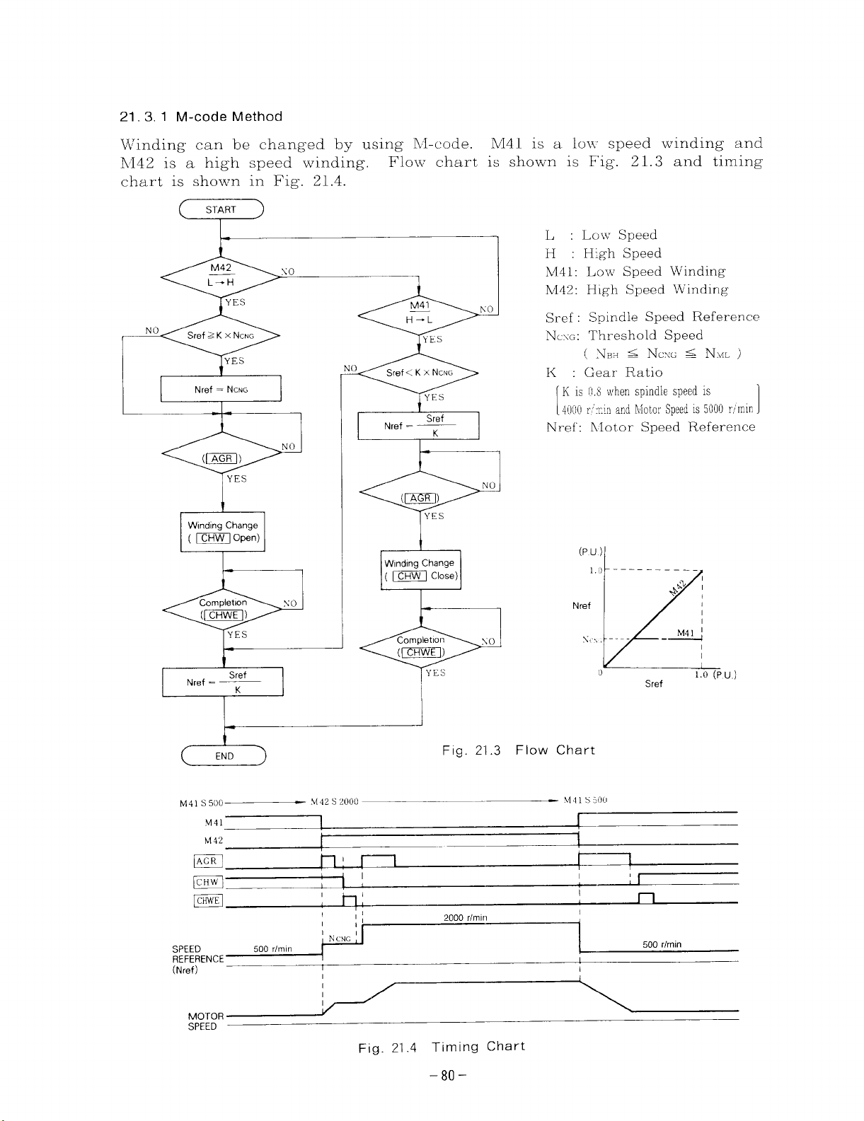
21.3, 1 M-code Method
Winding can be changed by using IV-code.
Iv142 is a high speed winding.
chart is shown in Fig.
1-
21.4.
Flow chart is shown is Fig.
r
NO
10
Nref = NCNG
I
I
IA
(cEm)
YES
NO
I
Nref = —
I
1- 1
i I
Sref
K
e
Wmdlng Change
( m C@n)
w
t- 1
Wlndmg Change
( = clO=)
L--#
M41 is a 10II speed winding and
21.3 and timing
L, : Low Speed
H : Hgh Speed
M41: Low Speed Winding
N442: High Speed Winding
Sref : Spindle Speed Reference
N.xG: Threshold Speed
( .VI++ s NCXG <
K :
Gear Ratio
K is ~1.8Whenspindlespeedis ‘
i[]o(\~.~.!nandLIOtOr
[
Nref: hlotor Speed Reference
(Pu)
1.) ––––––––––
Nref
NML )
spwlE, 5000 r~mm,
+L% ;
b
M 41 s 500
.M41
M42
m
m
m
>142 s 2000
,,,,,,N.,+
(Nref)
MOTOR
SPEED
Completion
(1-)
+
I
h:
I
[
1
hj
I
I
I
Fig. 21.4 Timing Chart
Xo
~E3
Fig. 2“1.3 Flow Chart
\l41 s
I
~
s,, , ----
0
:0(1
I
[
- M41 1
k
Sref
1
1
n
500 rlmin
1.0 (Pu)
-80-
Page 91

21. 3.2 Auto Winding Change Method
Llotor
~=1 and watching the actual
Fig. 21.5 and timing chart in Fig.
winding is automatically
N n /
,.”
(
START
Select HSW
(m Open)
1
Select LSW
(- Close)
*
switched by
motor speed.
21.6.
COmpletlOn No
(1-l)
YEs
using a
Flow chart is shown in
LSW : Low Speed Winding
HSW : High Speed Winding
Ncsc: : Threshold Speed
AN : Band width of Nc~G
Setting value of Cn-16 and Cn17 under Fig. are calculated
as below.
[
speed detect signal
Set Cn-16 of Control
Parameter
[
Set Cn-17 of Control
Parameter
[
C!n-lfj =
Cn-17 =
N,,, is Cn-21
NJ is
FJCX(3
—
NIOO
AN
— x 100
N,oo
from 100 through 200r/rein
x 100 %
1
1
1
END
(
Fig. 21.5 Flow Chart
)
s500
m~
ml
=~
s 2000
1 I
1,
,:
I I
2000 rlmin
Fig. 21.6 Timing Chart
.EIIiii&
s 500
–AN
r
(1
II
II
NCNG
(Cn-16)
+AN
–81–
Page 92

21.4 NOTES
.
If the magnetic contactor for motor winding selection is damaged or the
signal leads are disconnected, the spindle stops and operation program
does not proceed.
Check time and output alarm signal by using motor winding selection signal
and motor winding selection completion signal to inform worker of this
condition.
.
The frequency of operation of magnetic contactor for motor winding selection increases with this method, because motor winding is switched whenever
actual motor speed exceeds
.
Automatic winding selection is performed when the selection speed is reach-
ed even during cutting.
NCNG \Vhich is threshold speed.
As shown in Fig.
21.7, some roughness is seen in
rough-cutting, however, the closer to finishing, the smaller the error becomes.
Therefore, sufficient characteristics can be obtained for actual application.
lVhen further accuracy is required, check cutting face accuracy.
Cutting Width ?mm
Test conditions
. Workpiece : S45C ( # 100 rounded bar)
“ Bite : Super hard bite
“ Cutting speed : 150m/min
. Feeding : 0,2mm/rev
(a) Cutting Face Accuracy
Cutting W’idth 3mm
(b) Cutt
Fig 21.7 Face Accuracy Data at End Face Cutting by Lathe
Cutt:ng Width 4mm
:ing Face State
Cutting Width 5mm
-82-
Page 93

22. MAGNETIC CONTACTOR FOR WINDING SELECTION
22.1 RATING AND SPECIFICATIONS
HV-
75AP2
688-42
Table 22.1 Standard Specification
—
Contact Arrangement
Model h-o.
—
Rated Isolation Voltage
Rated operational Current
Maximum Braking Current
Maximum Operational Frequency
Mechanical Life
Rated Operational Voltage
Weight
Ambient Temperature
IIumidity
—
22.2 DIMENSIONS (in mm)
—=——__,
-- ~-= -—-~.. ..- ..-
(a) HV-75AP2
HV-75AP
Llam 3 N(I 3 KC Aux 1NO
75A (Cont. ) 87A (30min,
200.<
200V 50/60 Hz, 220V 50/60 Hz, 2301~ 6011z
2.5kg
10- 95% RH (non-condensing)
4M6
MOUNTING
HOLES
H1-150AP2
600V
?d$koED)- 150.A (Cont.), 175.+ (30min, 3396ED)
400A
600 operationsthour
5,000,000 operations
5,0kg
–lo to +-55°C
OPERATION
CIRCUIT TERMINAL
4-M6 MTG IHOLE
MAIN
CIRCUIT
TERMINAL ‘--- ‘“
(Ma)
(b) HV-150AP2
(M4)
b’,
..\
I
1
.,
+
OPERATION
Operation Main Contacts
@)– ‘g)
+
241?
ot~
Fig. 22.1 Dimension Diagram
Table 22.2 Operation
‘~-(~ ‘@-@ f(jj-@’
‘~).!~l
Open
Close
-83-
Aux
@).l@ ,Q.r@
a
[~ — ‘(jj
Close Open
Open Close
Page 94

Table 23.1 Causes and Check
Condition when
Problem
)Vcrct]rrcnt
(IOC)
:c.gcneratlvc
)vcrcurrcnt
(Cot)
)vcrvoltagc
(c)v)
Problem
$Qj~>it+<,’
& c
Fe ~~!:
o~
Occurs
, -A
Olrc
n’(:~
--f~
WW
~
z=
,]
s
~.
O?
,%’
Cl
I
,.. .
:q(ic>~
II
:1
~
Problem Cause
1
L)ecclcration from motor
speed more than N.,, with
]OW spcccf w]nding
Wrong connection of Imotor check ~onllcction,
main circuit
Bad magnetic contactor
for winding selection
–—-––—~
~ No power supply for MC 67 and 60 of MC,
..——.———
I
Oa
&
:,;:;, ‘[’CS ‘[)1
(’J
,,
Vinding Selc-
tlon dots not
:oInDlctc.
1’
~
~(][]:’,
Motor coasts
to stop.
,arge Vibration
md Noise
Abnomal Indi-
,,
4- - --------
0’
,1
,,
0 ,0
cation of Load
Meter
[
Wrong conn?ct]on or disconnc- I
ction of MC signal leads
,,
I
Bad magnetic contactor
~— .-—
Wrong connection or cfisconnection of main circuit cable
No power supply
Wrong connection or disconne- Check ~:(lnncctl(lrl
ct ion of MC signal leacls
for MC
Bad rnaxnet]c contactur
- { -----Wrong connection of main
circuit cable
~)-–
----1
Bad magnetic contactor ; main Contactor,
I
I
Check Method
Check wlrrdlng selection
c(]rr]mand and Speed reference. ~
----4--–-——--- -
Check conduction of
mam contacts.
Check the voltage bctwccn
.-—.
Check connection.”
1
~ Ch(:ck maxnct]c contaclor.
—.
Chcck connection
Check the voltage bctwccn
{17> :]rrcj @ of MC.
4
I
–.–J...
Check magnet.ic contact or.
Check connection.
~
Check corrduction of
Corructlvc ActIon
Changes srqucncc for
wlndln~ sclc>ct]on.
Correct cunncctlon of
]
main circuit.
Replace magnetic
contactor,
~ Connect cable to MC.
; CO I-I-eCt connection
----+—- ‘- -
~ Rcplacc magnetic
Coilta[:tor.
~ Correct corrnectlon.
—-----+–– ‘---— ---------
connect cable L() MC.
---i---Corr~ct cconncct II)n.
Rcplacc magnct)c
---+=’’ ------Correct connection.
l“--””
Replace magnetic
contactor.
Page 95

Magnetic Sensor Type Spindle Orientation
1
Magnetic sensor type spindle orientation system is used to stop the machine tool
spindle at a specified position by an electrical method. This system has the follow–
features:
in g
(1)
Simple mechanism
The spindle specified position stop functions are accomplished just by mounting
a magnetic unit on the spindle and a magnetic sensor on the stationary member.
(~)
Short orientation time
The position detection signal from the magnetic sensor forms a servo loop for
accurate positioning in a short period of time even when the spindle is running
at maximum speed.
Reliability and service life improvement
(3)
Substantial reduction of positioning shock leads to higher reliability and longer
service life .
Economical advantage
(4)
Simplified mechanism and power control sequence make for substantial reduc-
tion in cost.
1
24.
24.1
SPECIFICATIONS
SPINDLE ORIENTATION SPECIFICATIONS
Table 24.1 Standard Specifications
Item
Position
Detection Mode
Stop Position *
Accuracy of
Stop Position
Re~eatinq *
Reaction Torque *
Orientation Card
Magneto
Magnetic Sensor
x W’hen the magneto body is mounted on a 120mm
diameter outer surface, excluding mechanical erro
and error caused by external magnetic fields.
t Reaction torque may be reach continuous rated
torque on the setting method of gain.
Displacement detection based on the detection of magnetic flux
generated by a magneto and a magnetic senscr.
I
Position corresponding to the center-to center alignment of the
magneto body and the magnetic sensor head.
.Adjustable within + 1° with a potentiometer.
Continuous rated torque/ +0, 1° displacement t
Type JPAC-C345
I Types MG-137BS (standard) or MG-4555S
Types FS-1378C (standard) or FS-200A
Function
r
–85-
6hs l,.
Page 96

24.2 DETECTOR SPECIFICATIONS
Table 24.2 Magnetic Sensor Specifications
Item
Power
supply
OUtDUt
Servic
Output Terminal
Maker
*When magneto is mounted on 120 mm dia. outer surface on spindle
Voltage
Current
Position Signal
(level)
(for control)
(offset)
(output impedance)
Position Signal
(range)
(for monitor)
(offset )
Temperature Range
15VDC *5%
100 mA max
t4v min.
+(),2 v max
1.5kQ
min.*
30”
(+-2.4 V min.)
+0,5 V max
–lo”c to +56~c
With round connector
(Made by Tajiml Musen Denki K. K.)
(Terminal arrangement)
A: Position signal B: SG
c: +15V
D: Position signal –
E: Range signal –
F: Range signal +
MAKOME Corporation
FS-1378C
OUTPUT
++
OUTPUT
4
QDSPLACEMENT
Specifications
DISPLACEMENT
FS-200A
12 VDC~10%
50 mA max
+8V
+(3.2 V max
1.5 kfl
With 5 meter cable 6 mm
rubber-sheathed cable
[Wiring]
Red:
Black: SG
Green: Output +
White: Output –
-. .
mln,
OUTFLIT
+
-12V
o
DISPLACEMENT
dia, 4-co;
Table 24.3 Magneto Specifications
Item
Detection Range mm
(inches) (to.59)
Mass
g(lb)
Maker
Specifications
NIG-1378BS
f15
(0.Y73)
Makome Corporation
1-
–86-
I
1
*7
(~0.28)
10000
14.8
(0.033)
Page 97

2!5. SYSTEM CONFIGURATION
The spindle orientation system is composed of spindle AC motor, a VS-626MTIII
controller, an orientation card,
sensor.
See Fig, 25.1.
NC PANEL
-——..————— ~
I
I
I
I
!
I
ORIENTATION
1
GEAR
I
I SELECTION
SIGNAL
I
I ORIENTATION
COMPLETION
~ SIGNAL
L______ –____
I
I
I
I
a spindle position detector magneto and a magnetic
VS-626MTM
CONTROLLER
SPINDLE
AC
MOTOR
MAGNETIC SENSOR
-7--
MAGNETO
SPINDLE
!
[
—
z
“!
SPEED CHANGE MECHANISM
(GEAR oR 6ELT)
1
“3
I
TOOL
#
Fig. 25.1 Spindle Orientation System Configuration
–87-
Page 98

cm
co
SENSOR
j5~~
CONTROL POWER ~18 ~ ,5V
6
0
t12v
~19 ~v
R
,—1
MAGNETIC
SENSOR
I
J
IN-POSITION1
SIGNAL ~
-----&-
.--O—G--<O% NCR
L––––––.–– (J
I
I
N-CREEP <
I
D,
A,
A,
A,
ORCS
WR
RD
RST
GUP
0
b
L
0
:17
X5
X21
X25
20
16
iP
I SLOW-DOWN (1, I
SLOW-DOWN (2)
LG MG HG
TEST-MODE
(
‘F-OFS
~ FLD
ORE
—
—
1
—
o
c
-1
r
-
z
m
‘L—.
FIR—
NC-SIDE
—
—
Fig. 26.1 Outline of Orientation Control
—
—
—
—
Page 99

26.2 ORIENTATION OPERATION
The VS-626MTIII has two operating modes:
the normal mode in which the spindle
is controlled by external orientation signals, and the test mode in which the spindle
i:; controlled by card test signals for adjustment.
26.2.1 Normal Mode
When an orientation signal is received while the spindle is in motion (or standing
still) , the spindle immediately decelerates (or accelerates) to the preset orientation
speed.
When the spindle passes the target stop position first time after attaining the
preset speed, the soft start function incorporated in the orientation card is
started, and the spindle
then, as the magneto comes into alignment with the magnetic sensor,
by the servo loop.
Thereupon, the O-END LED (green) lights, and an
(:ontact CLOSE) .
After stopping at the specified angular position,
to remain in the position until the command is cleared, so that it resists anY external force exerted to displace it from the stop position.
Fig, 26.2 shows the time chart for normal mode orientation operation.
RUN SIGNAL
(FWD OR REV)
ORIENTATION SIGNAL
(ORT)
OPERATION COMPLETION
(ORE) SIGNAL
SPEED (RPM)
— COMMAND
_ _ ACTUAL
—
(
is first decelerated to the preset creep speed, and
ORE signal is output
the spindle is under control
_————_____________ ———_______________ ~
1
1
t
SPEED
I
“
ORIENTATION
SPEED
\,
i
)
o
Ar-----< -
—.~
CREEP :
SPEED
[
MOTION
(ATC)
it is stopped
(a) Orientation when Spindle is Running
OPERATION COMPLETION
(ORE) SIGNAL
SPEED (RPM)
— COMMAND
(--
_ ACTUAL
SPEED
) ~
(b) Orientation when Spindle is at Standstill
Fig. 26.2 Time Chart for Normal Mode Orientation
—.~
I
I
I
f
o
\ I-EEA ~~
I
I
–89-
Page 100

26. 2.2 Test Mode
When the selection connector on
in the test mode, the LED (red)
With ORT (orientation signal)
to run at the orientation speed.
the first time after TPB is ‘released,
the orientation card (JPAC-C345) is connected
built into the test button [ TPB] lights.
input, when TPB is pushed, the spindle starts
When the spindle passes the sto~ ~osition for
. .,
the spindle stopping sequence, same as in
the normal mode, is started to shortly stop the spindle at the specified an gular
position,
Upon stopping the spindle, the O-END LED (green) lights, but no ORE signal
is output, so that the spindle can be repeatedly tested for the orientation motion
with the TPB button ,
Fig . 26.3 shows the time chart for the test mode orientation operation.
ORIENTATION SIGNAL (ORT)I
TEST SIGNAL (TPB)
ORIENTATION COMPLETION
(ORE) SIGNAL
SPEED (RPM) ORIENTATION SPEED
REFERENCE
—-— ACTUAL SPEED ‘,
[–
POSITION SIGNAL
(MAGNETIC SENSOR
OUTPUT)
Note:
may be created with a system in \vhich an orientation time monitoring arrange
ment is incorporated. With these systems , the relevant parameter or
timer setting should be changed for the intended orientation test in advance.
Since no
ORE signal is output in the test mode, a time-error state
I
t
~’
)~
n A
CREEP SPEED
S---l-LED “O-END” LIT ~--
‘,,
1>”1
A
A A
v
Fig. 26, 3 Time Chart for Test Mode Orientation
27 WIRING SPECIFICATIONS
27.1 INTERCONNECTIONS BETWEEN DEVICES
27,1.1
For Type FS-1378C
JPAC-C345
ORfENTA~5CN
CARD
POSITION
~#~1’&oNTROL) @
POSITION
SIGNAL
(FOR MONITOR) @
@ ::1
[
Q ’71
{
–15V
SG ‘g
*Made by Honda Tsushin Kogyo K.K
Note
1 Connection lead should be vinyl cable with braided copper shield
(O 3mm2 twisted-pair 3-P), and the distance should be within 20m
2 ~ shOws twisted-pair leads
‘ 61
18
hR-20LF*
/-.
II
1P
1
I
1P
II
II
Ip
I
“~
.
I
MAGNETIC
A
SENSOR !
AMPLIFIER ~
D
E
F
c
FSD-1378C
~:
:,.
-A
‘METAL CONNECTOR
(ACCESSORY)
SENSOR
HEA#
v
FSH-1378C
-90-
 Loading...