

Page 1
Page 2

Preface
How to Change the Digital Operator Display from Japanese to English
The VARISPEED-626MC5Series of general-purposeInvertersprovidesV/f control and vector control as standard features along with user-friendly operation.
This manual is designed to ensure correct and suitable application of VARISPEED-626MC5-series
Inverters.Readthis manual beforeattemptingto install,operate,maintain, orinspectan Inverter and
keep it in asafe, convenient locationfor futurereference. Beforeyou understandall precautionsand
safety information before attempting application.
i
Page 3
Safety Information
The following conventionsare used to indicateprecautions in this manual. Failure to heed precautions provided
in this manual canresult in seriousor possibly even fatalinjury ordamageto theproducts orto relatedequipment
and systems.
!
WARNING Indicates precautions that, if not heeded, could possibly result in loss of life or
CAUTION Indicates precautions that, if not heeded, could result inrelatively serious orminor
!
The warning symbolsfor ISO and JIS standards are different, as shown below.
The ISO symbol is used in this manual.
Bothofthesesymbols appearon warninglabelson Yaskawaproducts.Pleaseabide by thesewarninglabelsregard-
lessof whichsymbol isused.
serious injury.
injury, damage to the product, or faulty operation.
ISO JIS
Yaskawa, 2000
All rights reserved. No part of this publication may be reproduced, stored in a retrieval system, or transmitted,
in any form, or by any means, mechanical, electronic, photocopying, recording, or otherwise, without the prior
writtenpermissionof Yaskawa. Nopatentliability isassumedwith respectto theuse of theinformation contained
herein. Moreover, because Yaskawa is constantly striving to improve its high-quality products, the information
contained in this manual is subject to change without notice. Every precaution hasbeen taken in the preparation
of this manual. Nevertheless, Yaskawa assumes no responsibility for errors or omissions. Neither is any liability
assumed for damages resulting from the use of the information contained in this publication.
ii
Page 4

Visual Aids
How to Change the Digital Operator Display from Japanese to English
The following aids are used to indicate certain types of information for easier reference.
AEXAMPLE"
INFO
IMPORTANT
Indicates application examples.
Indicates supplemental information.
Indicates importantinformation that should be memorized.
iii
Page 5

General Precautions
D The diagrams in this manual may be indicated without covers or safety shields to show de-
tails. Be sure to restore covers or shields before operating the Units and run the Units according to the instructions described in this manual.
D Any illustrations, photographs, or examples used in thismanual are provided as examples
only and may not apply to all products to which this manual is applicable.
D The products and specifications described in this manual or the content and presentation
of the manual may be changed without notice to improve the product and/or the manual.
D When ordering a newcopy of the manual due to damage orloss, contact your Yaskawarep-
resentatives or the nearest Yaskawa sales office and provide the manual number shownon
the front cover.
D If nameplates become warn or damaged, order new ones from your Yaskawa representa-
tives or the nearest Yaskawa sales office.
iv
Page 6

Safety Precautions
J Confirmations upon Delivery
D Never installan Inverter that is damaged or missing components.
Doing so can result in injury.
J Installation
D Always hold the case when carryingthe Inverter.
If the Inverter is held by the front cover, the main body oftheInvertermay fall,possiblyresultingininjury.
D Attach the Inverterto a metal or othernoncombustible material.
Fire can result if the Inverter is attached to a combustible material.
D Install a cooling fan or other cooling device when installing more thanone Inverter in
thesame enclosureso thatthe temperatureof the airentering theInvertersis below
45_C.
Overheating can result in fires or other accidents.
J Wiring
D Always turn OFF the input power supply before wiring terminals.
Otherwise, an electric shock or fire can occur.
D Wiring mustbe performed by an authorized person qualified in electricalwork.
Otherwise, an electric shock or fire can occur.
D Be sure to ground the ground terminal.
(200 V class:Ground to 100 : or less,400 V class:Ground to 10 : or less)
Otherwise, an electric shock or fire can occur.
D Always check the operationof any emergency stop circuits after they are wired.
Otherwise, there is the possibility of injury. (Wiring is the responsibility of the user.)
D Never touch the outputterminalsdirectlywith yourhands orallow theoutput lines to
come into contact with the Invertercase. Never short the outputcircuits.
Otherwise, electrical shock or grounding can occur.
How to Change the Digital Operator Display from Japanese to English
CAUTION
Page
NO TAG
CAUTION
Page
NO TAG
NO TAG
NO TAG
WARNING
Page
NO TAG
NO TAG
NO TAG
NO TAG
NO TAG
CAUTION
D Check to be sure that the voltage of the main AC power supply satisfies the rated
voltage of the Inverter.
Injuryor firecan occurif the voltageis not correct.
D Do not perform voltage withstand tests on the Inverter.
Otherwise, semiconductor elementsand other devices can be damaged.
D Connectbrakingresistors,BrakingResistor Units, and BrakingUnits as shownin the
I/O wiring examples.
Otherwise, a fire can occur.
D Tighten allterminal screws to the specified tightening torque.
Otherwise, a fire may occur.
D Do not connect AC power to output terminals U, V,and W.
Theinteriorparts of theInverterwill bedamagedif voltage is applied tothe output terminals.
v
Page
NO TAG
NO TAG
NO TAG
NO TAG
NO TAG
Page 7
CAUTION
D Do notconnect phase-advancingcapacitors orLC/RC noisefilters to the outputcir-
cuits.
The Inverter can be damaged or internal parts burntif thesedevicesare connected.
D Do not connect electromagneticswitches or contactorsto the output circuits.
Ifa loadis connectedwhile the Inverter isoperating,surgecurrentwill cause the overcurrent
protection circuit inside the Inverter to operate.
J Setting User Constants
CAUTION
D Disconnect the load (machine, device) from the motor before autotuning.
The motor may turn, possibly resulting in injury or damage to equipment. Also, motor
constantscannot be correctly set withthe motorattachedto a load.
J Trial Operation
WARNING
D Check to besure thatthefrontcover is attached beforeturning ON the powersupply.
Do not remove the front cover during operation.
An electric shock may occur.
D Donot come closetothemachinewhen thefault reset functionis used.Ifthealarmed
is cleared,the machine may start movingsuddenly.
Also, design the machine so that human safety is ensured even when it is restarted.
Injury may occur.
D Provide a separateemergency stop switch;the Digital OperatorSTOP Key is valid
only when its function is set.
Injury may occur.
D ResetalarmsonlyafterconfirmingthattheRUN signalis OFF. If an alarmis resetwith
the RUN signal turned ON, the machine may suddenly start.
Injury may occur.
CAUTION
D Don’t touch the radiation fins (heat sink), braking resistor,or Braking Resistor Unit.
These can become very hot.
Otherwise, a burn injury mayoccur.
D Be sure that the motor and machine is within the applicable ranges before starting
operation.
Otherwise, an injury may occur.
D Provide a separate holding brake if necessary.
Otherwise, an injury may occur.
D Don’t check signals whilethe Inverter is running.
Otherwise, the equipment may be damaged.
D Becarefulwhen changing Invertersettings.The Inverteris factory set to suitableset-
tings.
Otherwise, the equipmentmay be damaged.Youmust,however,you must set the powersupply voltage jumperfor 400 V classInvertersof 18.5 kW or higher(see NO TAG).
NO TAG
NO TAG
Page
NO TAG
Page
NO TAG
NO TAG
NO TAG
NO TAG
Page
NO TAG
NO TAG
NO TAG
NO TAG
NO TAG
vi
Page 8
How to Change the Digital Operator Display from Japanese to English
J Maintenance and Inspection
WARNING
D Do not touch the Inverterterminals. Some of the terminals carry high voltages and
are extremelydangerous.
Doing so can result in electric shock.
D Alwayshave the protectivecoverin place whenpowerisbeing suppliedto theInvert-
er. When attaching the cover, always turn OFF power to the Inverter through the
MCCB.
Doing so can result in electric shock.
D AfterturningOFFthemain circuitpower supply,waituntil the CHARGEindicatorlight
goes out before performance maintenance or inspections.
The capacitor will remain chargedand is dangerous.
D Maintenance, inspection,and replacement of parts must be performed only by au-
thorized personnel.
Remove allmetal objects,such as watches and rings, beforestarting work.Always
use grounded tools.
Failure to heed these warning can result in electric shock.
CAUTION
D ACMOS IC is used inthecontrolboard.Handlethe controlboardand CMOS ICcare-
fully. The CMOS IC can be destroyed by staticelectricity if touched directly.
The CMOS IC can be destroyed by static electricity if touched directly.
D Do not change the wiring,or remove connectorsor the DigitalOperator,during op-
eration.
Doing so can result in personalinjury.
J Other
WARNING
D Do not attempt to modify or alter the Inverter.
Doing so can result in electrical shock or injury.
Page
NO TAG
NO TAG
NO TAG
NO TAG
Page
NO TAG
NO TAG
vii
Page 9

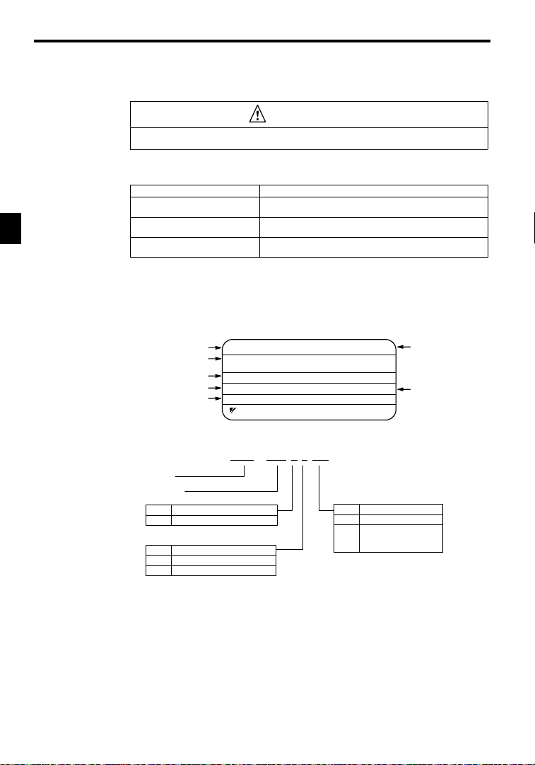
Warning Label Contents and Position
There is a warning label on the Inverter in the position shown in the following illustration. Always heed the warnings given on thislabel.
6
2
6
M
C
5
Warning label
position
Illustration shows the CIMR-MC5A23P7
Warning Label Contents
WARNING
S
S 1
S
May cause injury or electric
shock.
S Please follow the instructions in
the manual before installation or
operation.
S Disconnect all power before opening
front cover of unit. Wait 1 minute
until DC Bus capacitors discharge.
S Use proper grounding techniques.
viii
Page 10
How to Change the Digital Operator Display from Japanese to English
How to Change the Digital Operator Display from Japanese to English
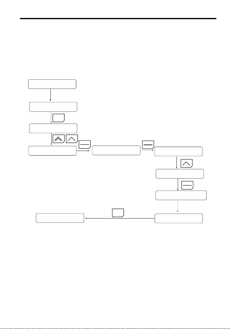
Ifthe DigitalOperator displaysmessagesin Japanese,change to the English mode using thefollowing steps.
(This manual provides descriptions for the English mode.)
Power ON
U1--01=0.00 HZ
MENU
MC5
MC5
Main Menu
Operation
DATA
ENTER
(Language)
(Japanese)
MENU
ix
DATA
ENTER
A1--00=1
(Japanese)
A1--00=0
English
ENTER
Entry Accepted
Select language
English
DATA
Page 11

Before Reading This Manual
V
This manual explains both the conventional VS--626MC5 Inverters and the MC5--series Inverters
for SPEC: F.
The shaded sections or those specified as being for SPEC: F apply only to MC5--series Inverters for
SPEC: F (Inverters with revised version letters of F or later.)
Be certain to check the specification on the Inverter nameplate.
Example of Inverter Nameplate
MODEL : CIMR--MC5A20P4 SPEC: 20P41F
INPUT : AC 3PH 200-220 V 50Hz
OUTPUT: AC 3PH 0-230 V 1.2kVA 3.2 A
LOT NO : MASS : 3.0kg
SER NO :
YASKAWA ELECTRIC COR PORATION
200-230 V 60Hz
JAPAN
ersion code
x
Page 12

CONTENTS
11 Introduction
12 Handling Inverters
13 Wiring
14 Setting User Constants
15 Trial Operation
16 Basic Operation
17 Advanced Operation
18 User Constants
19 Troubleshooting
10 Maintenance and Inspection
1
2
3
4
5
6
7
8
9
10
11 Specifications
12 Appendix
xi
11
12
Page 13

Table of Contents
1 Introduction 1 - 1.........................................
1.1 Outline and Functions 1 - 2........................................
1.1.1 VS-626MC5 InverterModels 1 -2.............................................
1.1.2 Outline of Control Methods 1 -4...............................................
1.1.3 Functions 1 - 4.............................................................
1.2 Nomenclature 1 - 7...............................................
1.2.1 VS-626MC5 Components 1- 7................................................
1.2.2 Digital Operator Components 1- 8.............................................
2 Handling Inverters 2 - 1...................................
2.1 Confirmations upon Delivery 2 - 2..................................
2.1.1 Nameplate Information 2 - 2..................................................
2.2 Exterior and Mounting Dimensions 2 - 4.............................
2.3 Checking and Controlling the Installation Site 2 - 6.....................
2.3.1 Installation Site 2 - 6........................................................
2.3.2 Controlling the Ambient Temperature 2 - 6.......................................
2.3.3 Protectingthe Inverter from Foreign Matter 2 -6..................................
2.4 Installation Orientation and Space 2 - 7...............................
2.5 Removing/Attaching the Digital Operator and
Front Cover 2 - 8
2.5.1 Invertersof 15 kW or Less 2 -8...............................................
2.5.2 Invertersof 18.5 kW or Higher 2 -9............................................
3 Wiring 3 - 1..............................................
3.1 Connections to Peripheral Devices 3 - 3..............................
3.2 Connection Diagram 3 - 4.........................................
3.3 Terminal Block Configuration 3 - 5..................................
3.4 Wiring Main Circuit Terminals 3 - 6.................................
3.4.1 ApplicableWire Sizes and Closed-loopConnectors 3 -6............................
3.4.2 Main Circuit Terminal Functions 3 -9...........................................
3.4.3 Main Circuit Configurations 3 -10..............................................
3.4.4 Standard Connection Diagrams 3 -12............................................
3.4.5 Wiring the Main Circuits 3 - 13.................................................
3.5 Wiring Control Circuit Terminals 3 - 20...............................
3.5.1 Wire Sizes and Closed-loop Connectors 3 - 20.....................................
3.5.2 Control Circuit Terminal Functions 3- 21.........................................
3.5.3 Control Circuit Terminal Connections(All Models) 3 -22............................
3.5.4 Control Circuit Wiring Precautions 3 - 23.........................................
3.6 Wiring Check 3 - 23...............................................
3.7 Installing and Wiring PG Speed Control Cards 3 - 24.....................
3.7.1 Installing a PG Speed Control Card 3- 24.........................................
3.7.2 PG Speed Control Card Terminal Blocks 3 - 25....................................
3.7.3 Wiring a PG Speed Control Card 3 -26...........................................
3.7.4 Wiring PG Speed ControlCard TerminalBlocks 3 -28...............................
3.7.5 Selectingthe Numberof PG (Encoder) Pulses 3 -30.................................
4 Setting User Constants 4 - 1................................
4.1 Using the Digital Operator 4 - 2.....................................
xii
Page 14

Tableof Contents
4.2 Modes 4 - 4....................................................
4.2.1 InverterModes 4 - 4........................................................
4.2.2 Switching Modes 4 -5.......................................................
4.2.3 User Constant Access Levels 4 - 6..............................................
4.2.4 OperationMode 4 - 11.......................................................
4.2.5 Initialize Mode 4 - 18........................................................
4.2.6 Programming Mode 4 -26....................................................
4.2.7 Autotuning Mode 4 -29......................................................
4.2.8 Modified Constants Mode 4 -31................................................
5 TrialOperation 5 - 1......................................
5.1 Procedure 5 - 3..................................................
5.2 Trial Operation Procedures 5 - 4....................................
5.2.1 Power ON 5 - 4............................................................
5.2.2 Checking the Display Status 5- 4..............................................
5.2.3 Initializing Constants 5 - 4....................................................
5.2.4 Setting Input Voltage 5 - 5....................................................
5.2.5 Autotuning 5 - 6...........................................................
5.2.6 No-load Operation 5 - 8......................................................
5.2.7 Loaded Operation 5 - 9......................................................
6 Basic Operation 6 - 1......................................
6.1 Common Settings 6 - 2...........................................
6.1.1 Setting the Access Level and Control Method: A1-01, A1-02 6 -2.....................
6.1.2 Frequency ReferenceSettings:b1-01, H3-01, H3-08, H3-09 6 -4.....................
6.1.3 Frequency Referencefrom Digital Operator: b1-01, o1-03, d1-01 to d1-09 6 - 7..........
6.1.4 Run Source and SequenceInput Responsiveness: b1-02, b1-06, b1-07 6 -9..............
6.1.5 Acceleration/Deceleration Times: C1-01 through C1-08, C1-09,C1-10, C1-11 6 -10.......
6.1.6 Prohibiting Reverse Operation: b1-04 6 - 11.......................................
6.1.7 Selectingthe StoppingMethod: b1-03 6 -12......................................
6.1.8 Multi-function Input Settings: H1-01 throughH1-06 6 -12...........................
6.2 Open-loop Vector Control 6 - 17.....................................
6.2.1 Autotuning for general-purpose motors 6 -17......................................
6.2.2 Autotuning for machine tool spindlemotors 6 -18..................................
6.2.3 Autotuning Faults 6 -21......................................................
6.3 Flux VectorControl 6- 22..........................................
6.3.1 PG Speed Control Card Settings 6 - 22...........................................
6.3.2 Setting the Zero-speed Operation Constants 6 - 25..................................
6.3.3 Autotuning for general-purpose motors 6 -27......................................
6.3.4 Autotuning for machine tool spindlemotors 6 -29..................................
6.3.5 Autotuning Faults 6 -31......................................................
6.3.6 Speed Control(ASR) Structure 6 - 32............................................
6.3.7 Speed Control (ASR) Gain 6 -34...............................................
7 Advanced Operation 7 - 1..................................
7.1 Open-loop Vector Control 7 - 2.....................................
7.1.1 TorqueLimit Function 7 -3...................................................
7.1.2 Adjusting Speed Feedback 7- 5...............................................
7.1.3 Setting/Adjusting Motor Constants 7 - 5.........................................
7.1.4 Operation Selectionwhen Output Voltage Saturated 7 - 8............................
7.1.5 Starting Torque Compensation Function (forSPEC: F) 7 -9..........................
7.2 Flux VectorControl 7- 10..........................................
7.2.1 TorqueLimit Function 7 - 11...................................................
7.2.2 Setting/Adjusting Motor Constants 7 -12.........................................
7.2.3 Operation Selectionwhen Output Voltage Saturated 7 - 16............................
7.3 Common Functions 7 - 17..........................................
7.3.1 ApplicationConstants:b 7 -18.................................................
7.3.2 Tuning Constants: C 7 -21....................................................
7.3.3 ReferenceConstants: d 7 - 24..................................................
7.3.4 Option Constants: F 7 - 26.....................................................
xiii
Page 15

7.3.5 External Terminal Functions:H 7 - 31............................................
7.3.6 ProtectiveFunctions:L 7 - 48..................................................
7.3.7 OperatorConstants:o 7 - 60...................................................
7.4 Optional Functions 7 - 64..........................................
7.4.1 Winding Change Function 7 - 64................................................
7.4.2 Wiring for WindingChange 7 - 66..............................................
7.4.3 Setting/Adjusting the WindingChange Constants 7 -69..............................
8 User Constants 8 - 1.......................................
8.1 Initialize Mode Constants 8 - 3.....................................
8.2 Programming Mode Constants 8 - 4.................................
8.2.1 ApplicationConstants:b 8 - 4.................................................
8.2.2 Autotuning Constants: C 8- 7.................................................
8.2.3 ReferenceConstants: d 8 - 12..................................................
8.2.4 Motor ConstantConstants: E 8 - 14..............................................
8.2.5 Options Constants: F 8- 18....................................................
8.2.6 Terminal Constants:H 8 - 21...................................................
8.2.7 ProtectionConstants:L 8 - 26..................................................
8.2.8 OperatorConstants:o 8 - 32...................................................
8.2.9 Winding Change Constants:P 8- 34.............................................
8.2.10 Factory Settings that Change with the Control Method (A1-02) 8 -35..................
8.2.11 Factory Settings that Change with the Inverter Capacity (o2-04) 8 -36..................
9 Troubleshooting 9 - 1......................................
9.1 Protective and Diagnostic Functions 9 - 2.............................
9.1.1 Fault Detection 9 - 2........................................................
9.1.2 Minor FaultDetection 9 - 6...................................................
9.1.3 Operation Errors 9 - 8.......................................................
9.2 Troubleshooting 9 - 9.............................................
9.2.1 If ConstantConstantsCannot Be Set 9- 9........................................
9.2.2 If the Motor DoesNot Operate 9 - 9............................................
9.2.3 If the Directionof the Motor Rotationis Reversed 9- 11.............................
9.2.4 If the Motor Does Not Put Out Torque or If Acceleration is Slow 9 - 11..................
9.2.5 If the Motor Does Not Operate According to Reference 9 - 11.........................
9.2.6 If the Slip Compensation Function HasLow Speed Precision 9 -11.....................
9.2.7 If Thereis Low Speed Control Accuracy at High-speed Rotation in Open-loop
Vector Control Mode 9 - 11....................................................
9.2.8 If Motor Deceleration is Slow 9 - 12.............................................
9.2.9 If the Motor Overheats 9 - 12...................................................
9.2.10 If Thereis NoiseWhen the Inverteris Started or From an AM Radio 9 -12..............
9.2.11 If the Ground FaultInterrupterOperates When the Inverter is Run 9 -13................
9.2.12 If There is Mechanical Oscillation 9 - 13.........................................
9.2.13 If the Motor Rotates Even When Inverter Output is Stopped 9 - 13.....................
9.2.14 If 0 V is Detected When the Fan is Started, or Fan Stalls 9 - 13........................
9.2.15 If Output Frequency Does Not Riseto Frequency Reference 9 -14.....................
9.2.16 Winding change errorhas occurred 9 - 14........................................
10 Maintenance and Inspection 10 - 1...........................
10.1 Maintenance and Inspection 10 - 3...................................
10.1.1 Daily Inspection 10 - 3......................................................
10.1.2 Periodic Inspection 10 - 3....................................................
10.1.3 Periodic Maintenanceof Parts 10 - 3............................................
11 Specifications 11 - 1........................................
11.1 Standard Inverter Specifications 11 - 2................................
11.2 Specifications of Options and Peripheral Devices 11 - 6...................
12 Appendix 12 - 1...........................................
12.1 Inverter Application Precautions 12 - 2................................
xiv
Page 16

Tableof Contents
12.1.1 Selection 12 -2...........................................................
12.1.2 Installation 12 - 2.........................................................
12.1.3 Settings 12 -3...........................................................
12.1.4 Handling 12 - 3..........................................................
12.2 Motor Application Precautions 12 - 4.................................
12.2.1 Usingthe Inverter for an Existing StandardMotor 12 - 4...........................
12.2.2 Usingthe Inverter for SpecialMotors 12 - 5.....................................
12.2.3 Power Transmission Mechanism (Speed Reducers,
Belts,and Chains) 12 -5...................................................
12.3 Peripheral Device Application Precautions 12 - 6........................
12.4 Wiring Examples 12 - 8.............................................
12.4.1 Using a Braking Resistor Unit 12 - 8............................................
12.4.2 Using a Braking Unit and Braking ResistorUnit 12 - 8..............................
12.4.3 Using TwoBraking Units in Parallel 12 -11....................................
12.4.4 Using Three Braking Resistor Units in Parallel 12 - 12..............................
12.4.5 Using a JVOP-95-j,-96-j VS Operator 12 - 13...................................
12.4.6 Using an Open-collector Transistorfor Operation
Signals 12 - 14............................................................
12.4.7 Using Open-collector,Contact Outputs 12 - 14.....................................
12.5 UserConstants 12 - 15..............................................
xv
Page 17

1
Introduction
This chapter provides an overview of the VS-626MC5 Inverter and describes its functions and components.
1.1 Outline and Functions 1 - 2....................
1.1.1 VS-626MC5 Inverter Models 1 - 2....................
1.1.2 Outline of Control Methods 1 - 4.....................
1.1.3 Functions 1 - 4....................................
1.2 Nomenclature 1 - 7..........................
1.2.1 VS-626MC5 Components 1 - 7......................
1.2.2 Digital Operator Components 1 - 8....................
1
-1
Page 18

Introduction
Maximum
p
listedattherigh
t
200
Vcl
p
listedattherigh
t
00Vcl
1.1.1 VS-626MC5 Inverter Models
1.1 Outline and Functions
1
Voltage
Class
4
The VS-626 MC5 Inverter is a compact spindle drive specially designed for machine tool application. MC5
Inverter has features such as winding change during operation, and autotuning function fordual winding motors.
TheVS-626MC5Invertersprovidesfull-currentvectorcontrolbased on advanced controllogic. Anautotuning
function is included for easy vector control.
The Digital Operatorprovides aliquid crystaldisplay that is 2 lines by 16 charactersin size. Userconstant settingsand monitoritems are easilyread in interactiveoperations in eitherJapaneseor English. (The display language can be changed by setting a user constant.)
1.1.1 VS-626MC5 Inverter Models
VS-626MC5Inverters are available in200 and 400V class models.These are listedin the followingtable.
A total of 32 models is available for motor capacities of 0.4 to 75 kW.
Table 1.1 VS-626MC5Inverter Models
Maximum
Applicable
ass
ass
Motor Out-
put [kW]
Output Ca-
pacity [kVA]
0.4 1.2 CIMR-MC5A20P4 20P41*
0.75 2.3 CIMR-MC5A20P7 20P71*
1.5 3.0 CIMR-MC5A21P5 21P51*
2.2 4.2 CIMR-MC5A22P2
3.7 6.7 CIMR-MC5A23P7
5.5 9.5 CIMR-MC5A25P5
7.5 13 CIMR-MC5A27P5 27P51 *
11 19 CIMR-MC5A2011 20111 *
15 24 CIMR-MC5A2015 20151 *
18.5 30 CIMR-MC5A2018 20180 * 20181 ‡
22 37 CIMR-MC5A2022 20220 * 20221‡
30 50 CIMR-MC5A2030 20300 † 20301‡
37 61 CIMR-MC5A2037 20370 † 20371‡
45 70 CIMR-MC5A2045 20450 † 20451‡
55 85 CIMR-MC5A2055 20550 † 20551‡
75 110 CIMR-MC5A2075 20750 ‡ 20751 ‡
0.4 1.4 CIMR-MC5A40P4 40P41*
0.75 2.6 CIMR-MC5A40P7 40P71*
1.5 3.7 CIMR-MC5A41P5 41P51*
2.2 4.7 CIMR-MC5A42P2
3.7 6.1 CIMR-MC5A43P7
5.5 11 CIMR-MC5A45P5
7.5 14 CIMR-MC5A47P5 47P51 *
11 21 CIMR-MC5A4011 40111 *
15 26 CIMR-MC5A4015 40151 *
18.5 31 CIMR-MC5A4018 40180 * 40181 ‡
22 37 CIMR-MC5A4022 40220 * 40221 ‡
30 50 CIMR-MC5A4030 40300 * 40301 ‡
37 61 CIMR-MC5A4037 40370 * 40371 ‡
45 73 CIMR-MC5A4045 40450 * 40451 ‡
55 98 CIMR-MC5A4055 40550 † 40551 ‡
75 130 CIMR-MC5A4075 40750† 40751‡
VS-626MC5
Model Number
Open Chassis Type
CIMR-MC5A
Remove the top and bottom
covers from the models
listed at the right.
Remove the top and bottom
covers from the models
listed at the right.
*: Immediatedelivery †: Available from factory ‡: Manufactured upon order
Inverter Specifications
(Specify all required standards when ordering.)
(IEC IP 00)
.
*
.
*
Enclosed Wall-mounted
Type
(IEC IP 20, NEMA 1)
CIMR-MC5A
22P21 *
23P71 *
25P51 *
42P21 *
43P71 *
45P51 *
-2
Page 19
1.1.2 Outline of Control Methods
The VS-626MC5 uses two control methods.
D Open-loop vector control (factory setting)
D Flux vector control
PG stands for pulse generator (encoder).
Vector control isa method for removinginterferencewithmagnetic flux and torque,andcontrolling torque
according to references.
Currentvectorcontrol independently controlsmagneticflux current and torquecurrent by simultaneously
controlling the motorprimary current and phases. Thisensures smooth rotation,high torque,and accurate
speed/torque control at low speeds.
If the motorconstants required forvector control arenot known, the motor constantscan be automatically
set with autotuning.
The control methods are effective for the following applications:
D Open-loop vector control: General variable-speed drive.
D Flux vector control: Simple servodrive, high-precision speed control/torque control.
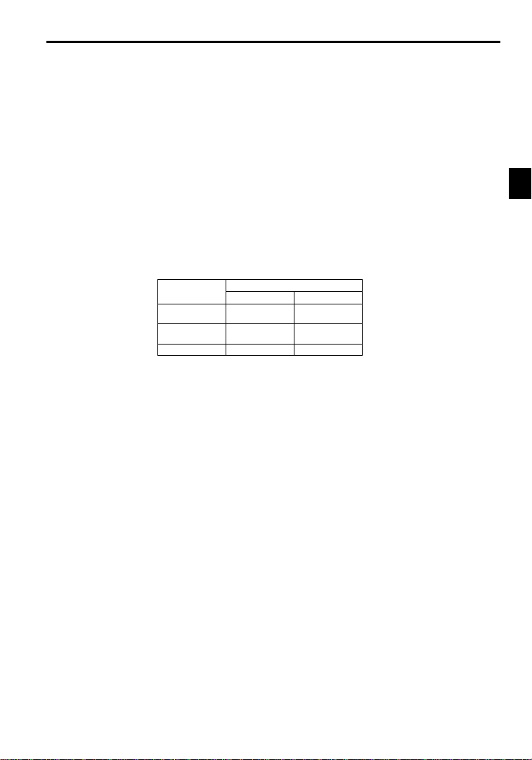
The control characteristics for each mode are shown in Table 1.2.
Table 1.2 ControlMethod Characteristics
Characteristic
Speed Control
Range
Speed Control
Precision
Initial Drive 150% at 1 Hz 150% at 0 r/min
Open-loop Flux Vector
1.1.3 Functions
J Autotuning
Autotuning is effectivefor vectorcontrol. It solves problems in applicable motorrestrictions and difficult
constant settings. The motor constants are automatically set by entering a value from the motor’s rating
nameplate.
Autotuning allows fluxvector control tooperate accurately withvirtually any normalAC induction motor,
regardless of the supplier.
Always perform autotuning for motor unit separately before vector control operation.
J Frequency References
Thefollowing five typesoffrequency references can beused to controlthe output frequencyof the Inverter.
D Numeric input from the Digital Operator
D Voltage input within a range from 0 to 10 V
D Voltageinput within arange from 0 to r10 V (with negative voltages,rotation is in the oppositedirec-
tion from the run command.)
D Current input within a range from 4 to 20 mA
D Input from Option Card
Any of the above frequency references can be used by setting a constant.
Amaximumof nine frequency references can beregisteredwith the Inverter.Withremote multi-step speed
reference inputs, the Inverter can operate in multi-step speed operation with a maximum of nine speed
steps.
J Low Noise
Theoutput transistorof the Inverteris an IGBT (insulated gatebipolar transistor).Using sine-wave PWM
with a high-frequency carrier, the motor does not generate metallic noise.
1.1Outlineand Functions
1
Vector Control
1:100 1:1000
0.2 % 0.02 %
-3
Page 20

1
Introduction
1.1.3 Functions
J Monitor Function
The following items can be monitored with the DigitalOperator: Frequencyreference, outputfrequency,
output current, motor speed, outputvoltage reference,main-circuit DC voltage, output power,torque reference,statusof input terminals,status of outputterminals, operating status,totaloperating time,software
number, speed deviation value, PID feedback value, fault status, fault history,etc.
All types of data can be monitored even with multi-function analog output.
J Bilingual Digital Operator
The Digital Operatorcan displayeither Englishor Japanese.The Digital Operator’s liquid crystal display
provides a 16-character x 2-line display area.
Easy-to-read displays allow the advanced functions of the Inverter to be set in interactive operations to
input constants, monitoring items, etc. Change the constant setting to select the English display.
J Harmonic Countermeasures (0.4 to 160 kW Models)
The VS-626MC5 Inverters support DC reactors to easily handle high-frequency control guidelines.
D DC reactors (optional) can be connected to 0.4 to 15 kW models.
D Models from 18.5 to 75 kW have a built-in DC reactor.
J User Constant Structure and Three Access Levels
The VS-626MC5 has a number of user constants for setting various functions. These user constants are
classified into a hierarchy to make them easier to use.
Thelevels areas followsfrom topto bottom:Modes, Groups,Functions, andConstants. The access levels
for the user constants are shown in Table 1.3.
Table 1.3 AccessLevels for User Constants
Level Contents
Mode Classified according to operation
Groups Classified by application.
Functions Classified by function. See user constants.
Constants Individualuser constant settings.
TheVS-626MC5 allowsthe following three access levelsto be set in order to further simplify setting user
constants. (An access level is a range of user constants that can be referenced or set.)
Quick-Start Reads/sets user constants required for trial operation. [Factory setting]
Basic Reads/setsuser constants that are commonly used.
Advanced Reads/sets all the user constants that can be used.
Operation: For operating the Inverter. (All kinds of monitoring are possible.)
Initialize: For selecting the language displayed at the Digital Operator,set-
Programming: For setting user constants for operation.
Autotuning: Forautomatic calculation or setting motor constants. (Only under
Modified constants: For referencing or changing user constants after shipping.
ting access levels, initialization, and the control modes.
the vector control mode.)
-4
Page 21
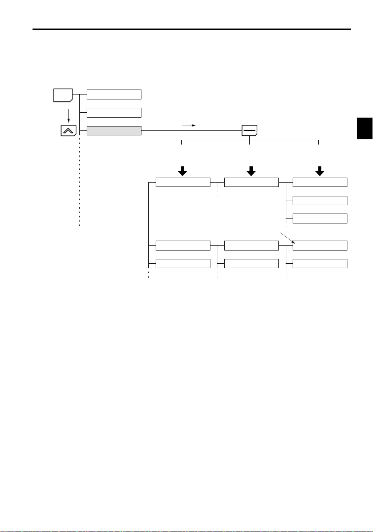
MENU
1.1Outlineand Functions
In general, press the DATA/ENTER Key to move from an upper to a lower level. This varies somewhat,
however, according to the access level, as shown in Fig. 1.1. For the Quick-Start access level, which has
fewuser constants that canbe set,pressingthe DATA/ENTERKey jumpsdirectlyto theuser constant level; whereas for the Advanced access level, which has many user constants, pressing the DATA/ENTER
Key first leads to the Group level.
Operation mode
Initialize mode
Programming mode
AdvancedBasicQuick-Start
Displays group level.
DAT
A
ENTER
Displays function level.
Displays constant level.
1
Mode
Fig 1.1 Access Level Structure
Application
Tuning
Reference
Groups
b1 Sequence
Constant to be changed
C1 Accel/Decel
C2 S-curve Acc/Dec
Functions
b1-01 Reference source
b1-02 Run source
b1-03 Stopping method
C1-01 Accel Time 1
C1-02 Decel Time 1
Constants
-5
Page 22
Introduction
1.2.1 VS-626MC5 Components
1
1.2 Nomenclature
Thissection provides thenames of VS-626MC5 components, andthe components andfunctions of the Digital
Operator.
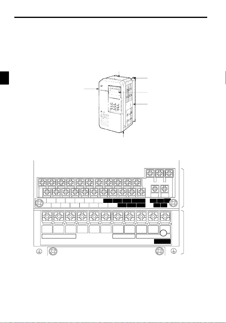
1.2.1 VS-626MC5 Components
The appearanceof Inverter and the names of its components are shown in Figure 1.2.
Protective cover (top)
Mounting hole
Front cover
6
2
6
M
C
5
Protective cover (bottom)
Digital Operator
JVOP-130
Die-cast case
Fig 1.2 Appearance of VS-626MC5, Model CIMR-MC5A20P4 (200 V,0.4 kW)
A 200 V Class Inverter with 0.4 kW Output is shown below with the front cover removed.
11 12(G) 13 14 15 16 17 25 26 27 33 18 19 20
1234567821 22 23 9
R
L1
S
L2
Power input
T
©
L3
¨1
¨2B1
Braking Resistor Motor output
U
B2
T1
V
T2
10
W/T3
CHARGE
Fig 1.3 TerminalArrangement
Control circuit
terminals
Main circuit
terminals
-6
Page 23
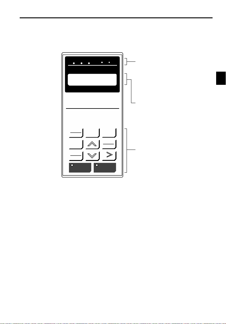
1.2.2 Digital Operator Components
Thissection describes thecomponent names and functions of theDigital Operator. The componentnames
and functions are shown in Figure 1.4 and key functions are described in Table1.4.
1.2Nomenclature
DRIVE FWD REV REMOTE
DIGITAL OPERATOR
JVOP-130
LOCAL
REMOTE
JOG
FWD
REV
SEQ REF
Frequency Ref
U1--01 = 00.00 HZ
MENU
RUN STOP
ESC
DATA
ENTER
RESET
Operation Mode Indicators
DRIVE: Lit when in operation mode.
FWD: Lit when there is a forward reference input.
REV: Lit when there is a reverse reference input.
SEQ: Lit when an operation reference from the
REF: Lit when the frequency reference from con-
Data Display
Two-line LCD that displays data for monitoring,
user constants, and set values with 16 characters
per line.
Keys
Execute operations such as setting user constants,
monitoring, jogging, and autotuning.
Fig 1.4 Digital Operator Component Names and Functions
control circuit terminal is enabled.
trol circuit terminals 13 and 14 is enabled.
1
-7
Page 24
Introduction
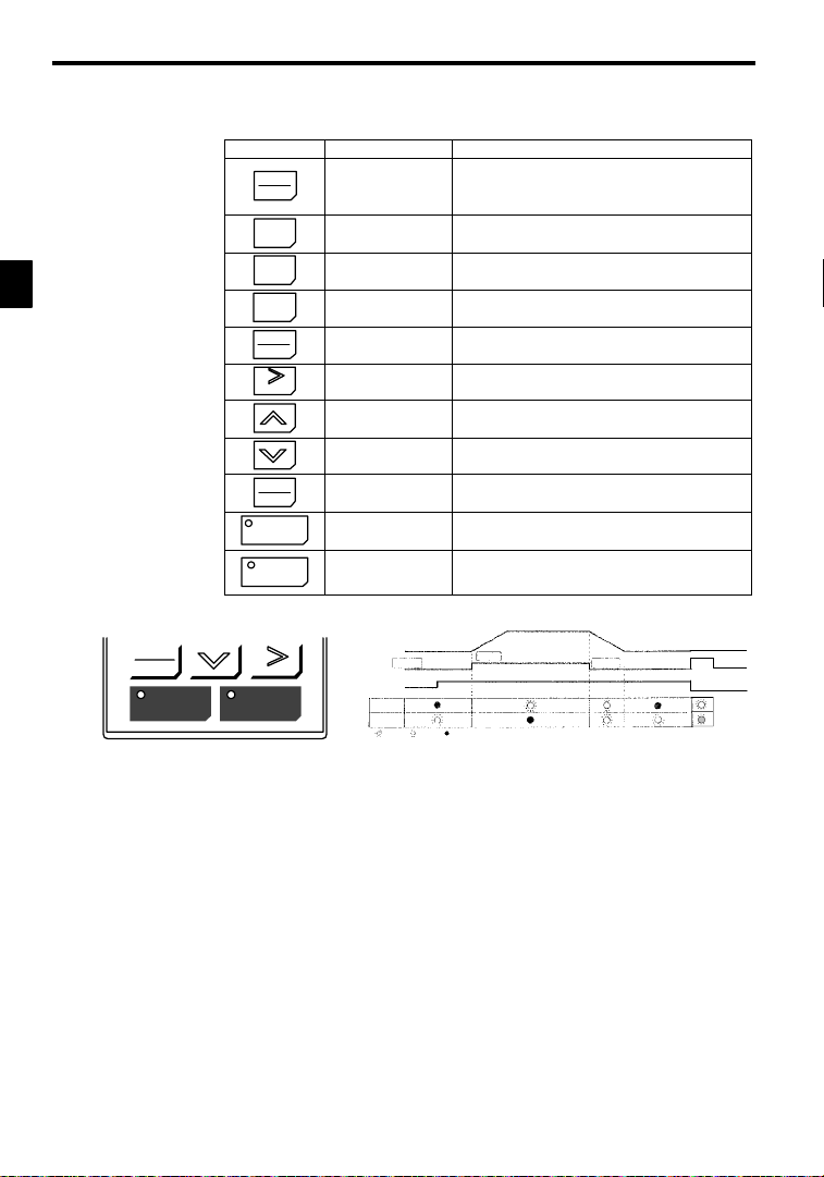
1.2.2 Digital Operator Components
1
Note Except in diagrams, keys are referred to using the key names listed in the above table.
FWD
REV
RUN STOP
Table 1.4 KeyFunctions
Key Name Function
LOCAL
REMOTE
MENU
FWD
RESET
LOCAL/REMOTE Key
MENU Key Displaysmenus.
ESC Key
ESC
JOG
JOG Key
FWD/REV Key
REV
RESET Key
Increment Key
Decrement Key
DAT
DATA/ENTER Key
A
ENTER
RUN
RUN Key
STOP
RESET
STOP Key
Inverter output frequency
Frequency setting
STOP
RUN
LitBlinkingNot lit
The RUN and STOP indicators light and blink to indicate operating status.
Switches between (LOCAL) operation via the Digital Operator
and control circuit terminal (REMOTE) operation.
This key can be enabled or disabled by setting a user constant
(o2-01).
Returns to the status before the DATA/ENTER Key was
pressed.
Enables jog operation when the VS-626MC5 is being operated
from the Digital Operator.
Selects the rotation direction of the motor when the
VS-626MC5 is being operated from the Digital Operator.
Sets the number of digits for user constant settings.
Also acts as the reset key when a fault has occurred.
Selects menu items, groups, functions, and user constant
names, and increments set values.
Selects menu items, groups, functions, and user constant
names, and decrements set values.
Enters menu items, functions, constants, and set values after
they are set.
Starts the VS-626MC5 operation when the VS-626MC5 is in
operation with the Digital Operator.
Stops VS-626MC5 operation.
This key can be enabled or disabled by setting a user constant
(o2-02) when operating from the control circuit terminal.
STOP
RUN
Fig 1.5 RUN and STOP Indicators
STOP
-8
Page 25

2
Handling Inverters
This chapter describes the checks required upon receiving a VS-626MC5
Inverter and describes installation methods.
2.1 Confirmations upon Delivery 2- 2..............
2.1.1 Nameplate Information 2 - 2.........................
2.2 Exterior and Mounting Dimensions 2 - 4.........
2.3 Checking and Controlling the Installation
Site 2 - 6..................................
2.3.1 Installation Site 2 - 6...............................
2.3.2 Controlling the Ambient Temperature 2 - 6..............
2.3.3 Protecting the Inverter from Foreign Matter 2 - 6.........
2.4 Installation Orientation and Space 2 - 7..........
2.5 Removing/Attaching the Digital Operator and
Front Cover 2 - 8............................
2.5.1 Inverters of 15 kW or Less 2 - 8......................
2.5.2 Inverters of 18.5 kW or Higher 2 - 9...................
2
-1
Page 26
Handling Inverters
2.1.1 Nameplate Information
2
2.1 Confirmations upon Delivery
CAUTION
D Never install an Inverter that is damaged or missing components.
Doing so can result in injury.
Check the following items as soon as the Inverter is delivered.
Table 2.1 Checks
Has the correct model of Inverter been
delivered?
Is the Inverter damaged in any way? Inspect the entire exterior of the Inverter to see if there are any scratches or
Are any screws or other components
loose?
If you find any irregularitiesin the aboveitems, contact the agency from which you purchasedthe Inverter or
your Yaskawa representative immediately.
2.1.1 Nameplate Information
J Example Nameplate
Input specifications
Output specifications
J Inverter Model Numbers
Inverter
VS-626MC5
Item Method
Check the model number o n the nameplate on the side of the Inverter (See
2.1.1).
other damage resulting from shipping.
Use a screwdriver or other tools to check for tightness.
Standard domestic (Japan) Inverter: 3-phase, 200 VAC,0.4 kW,IEC IP20 and NEMA 1 standards
Model number
Lot number
Serial number
MODEL : CIMR-MC5A20P4 SPEC: 20P41F
INPUT : AC 3PH 200-220 V 50Hz
OUTPUT: AC 3PH 0-230 V 1.2kVA 3.2 A
LOT NO : MASS : 3.0kg
SER NO :
YASKAWA ELECTRIC CORPORATION
CIMR -MC5A 2 0P4
No. Specification
A Standard domestic model
No. Voltage Class
2 AC input, 3-phase, 200 V
4 AC input, 3-phase, 400 V
200-230 V 60Hz
JAPAN
No. Max. Motor Capacity
0P4
0P7
to
075
“P” indicates the decimal point.
Inverter specifications
Mass
0.4 kW
0.75 kW
to
75kW
-2
Page 27

J Inverter Specifications
No. Voltage Class
2 AC input, 3-phase, 200 V
4 AC input, 3-phase, 400 V
2 0P4 1 F
2.1Confirmations upon Delivery
Version(Enter the specifications
form number when special specifications are required.)
No. Max. Motor Capacity
0P4
0P7
to
075
“P” indicates the decimal point.
0.4 kW
0.75 kW
to
75kW
D Open Chassis Type(IEC IP00)
Protected so that parts of the human body cannot reach electrically charged parts from the front when
the Inverter is mounted in a control panel.
D Enclosed Wall-mountedType (IEC IP20, NEMA 1)
The Inverter is structured so that the Inverter is shielded from the exterior,and can thus be mounted
to the interior wall of astandard building (not necessarily enclosed in a control panel). The protective
structure conforms to the standards of NEMA 1 in the USA.
No. Protective Structure
0
1
Open chassis (IEC IP00)
Enclosed wall-mounted (IEC IP20, NEMA 1)
2
-3
Page 28
Handling Inverters
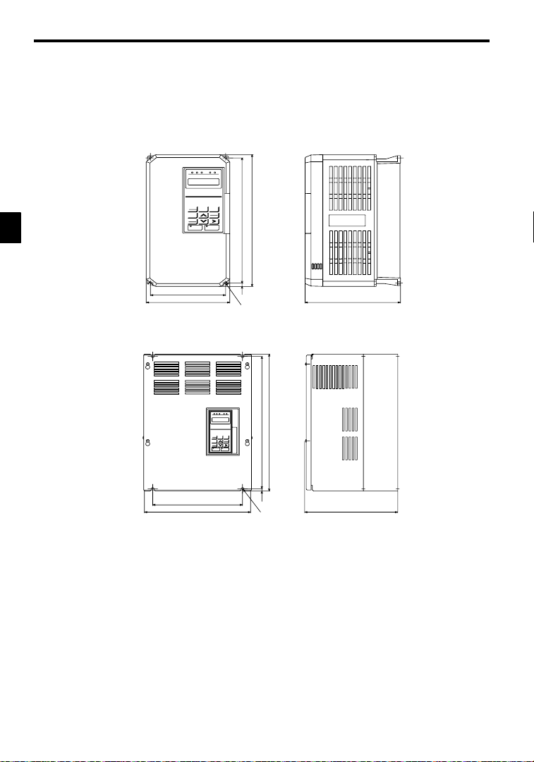
2.2 Exterior and Mounting Dimensions
J 200 V/400 V Class Inverters of 15 kW and Lower
The following diagram shows a 200 V class, 1.5 kW Inverter.
Remove the top and bottom covers when mounting 200 V/400 V class Inverters of 15 kW or lower in a
control panel.
2
W1
W
H1
H
H2
4-d
D
J 200 V/400 V Class Inverters of 18.5 kW and Higher
The following diagram shows a 200 V class, 18.5 kW Inverter.
H 1
H
W1
W
H2
4-d
D
-4
Page 29

2.2Exterior and Mounting Dimensions
Vol
l
icab
l
D
C
5
tio
n
200
V
5
5
5
5
i
n
5
54.5
tio
n
400
V
5
5
5
5
i
n
5
5
5
5
Max. Ap-
t-
p
Motor Out-
put
[kW]
e
age
class
0.4
0.75
1.5
2.2
3.7
5.5
7.5
11
200 V
class
15
18.5
22
30
37
45
55
75 575 925 400 445 895 15.0 135 580 1290 400 445 895 270 145 M12
0.4
0.75
1.5 4 4
2.2
3.7
5.5
7.5
11
400 V
class
15
18.5
22
30
37
45 850 152.5
55
75
* 1. Same for open chsassis and enclosed wall-mounted types.
* 2. See page - 4 for mounting dimensions.
Note An attachment is required to mount the cooling fins (finsection) on the outside of the control panel for200 V/400 V class
Invertersof 15 kWor less. Please ask yourYaskawarepresentative for details. Dimensionaldrawings for models with externally mounted cooling fins and other special requirements are also available from your Yaskawa representative.
Open Chassis (IP00) Enclosed Wall-mounted (NEMA1)
W H D W1 H1 H2
Approx.
W H D W1 H1 H2
Mass
Approx.
Mass
140 280 160 126 266 7.0 3 140 280 160 126 266 7.0 3 M5
140 280 180 126 266 7.0 4.5140 280 180 126 266 7.0 4.5M
200 300 205186 2858.0
5.5
6
250 380 225236 3657.511 250
325450 2852754357.528 330
425675350 320 650 12.
61
62
200 300 205186 2858.0
380
225236 36
400
610
28527543
675
430 985350 320 650 212.
5.5
7.5
27.5
87.5
152.5
475800 350 370 77512.580 480 1110 350 370 775212.587 M10
140 280 160 126 266 7.0 3 140 280 160 126 266 7.0 3 M
140 280 180 126 266 7.0
140 280 180 126 266 7.0
4.
200 300 205186 2858.0 6 200 300 205186 2858.0 6 M6
250 380 225236 3657.511 250 380 225236 3657.511 M6
325450 2852754357.
325 625 285 275 610 7.5 44 330
4
820 350 350 79512.
29
330 610 28527543587.
31
78
285 275 610
81
460 1130 350 350 795212.
82
87.
Table 2.2 VS-626MC5External Dimensions (mm) and Approx. Masses (kg)
Mounting
Holes
6
11 M6
32 M6
67
M10
68
32
34
48 M6
87
M10
88
d*1
M6
M5
M6
Reac-
tor
Option
Built-
in
Option
Built-
in
*1
2
-5
Page 30
2
Handling Inverters
2.3.1 Installation Site
2.3 Checking and Controlling the Installation Site
CAUTION
D Always hold the case when carrying the Inverter.
IftheInverteris held by the front cover,the main body oftheInvertermayfall, possibly resulting in injury.
D Attach the Inverter to a metal or other noncombustible material.
Fire can result if the Inverter is attached to a combustible material.
D Install a cooling fan or othercooling device when installing more than oneInverter in the same
enclosure so that the temperature of the air entering the Inverters is below 45_C.
Overheating can result in fires or other accidents.
Install the VS-626MC5 in the installation site described below and maintain optimum conditions.
2.3.1 Installation Site
Install the Inverter under the following conditions.
Type Ambient Operating Temperature Humidity
Enclosed wallmounted
Open chassis
Protectioncoversareattachedto the topandbottom of the Inverter.Be sure to removethe protectioncovers
before installing a 200 or 400 V Class Inverter with an output of 15 kW or less in a panel.
D Install theInverter in aclean location freefrom oil mist anddust. It canbe installed ina totally enclosed
panel that is completely shielded from floating dust.
D When installing or operating theInverter, always take special careso that metal powder,oil, water,or
other foreign matter does not get into the Inverter.
D Do not install the Inverter on combustible material, such as wood.
D Install the Inverter in a location free from radioactive materials and combustible materials.
D Install the Inverter in a location free from harmful gasses and liquids.
D Install the Inverter in a location without excessive oscillation.
D Install the Inverter in a location free from chlorides.
D Install the Inverter in a location not in direct sunlight.
2.3.2 Controlling the Ambient Temperature
To enhance the reliability of operation, the Inverter should be installed in an environment free from extreme temperature increases. If the Inverter is installed in an enclosed environment, such as a box, use a
cooling fan or air conditioner to maintain the internal air temperature below 45qC.
2.3.3 Protecting the Inverter from Foreign Matter
Place a cover over the Inverter during installation to shield it from metal power produced by drilling.
Always remove the cover from the Inverter after completing installation. Otherwise, ventilation will be
reduced, causing the Inverter to overheat.
--10 to 40_C
--10 to 45_C
90% RH or less (no condensation)
90% RH or less (no condensation)
-6
Page 31

2.4 Installation Orientation and Space
Install the Inverter on a vertical surfaceso as not to reduce the cooling effect. When installingthe Inverter,always provide the following installation space to allow normal heat dissipation.
2.4Installation Orientation and Space
IMPORTANT
50 mm min.
120 mm min.
30 mm min. 30 mm min.
50 mm min.
(a) Horizontal Space
Fig 2.1 VS-626MC5 Installation Orientation and Space
S The same space is required horizontally and vertically for both open chassis (IP00) and enclosed
wall-mounted (IP20, NEMA 1) Inverters.
S Always removethe protection covers before installing a 200 or 400 V Class Inverter with an output
of 15 kW or less in a panel.
S Always provide enough space for suspension eye bolts and the main circuit lines when installing a
200 or 400 V Class Inverter with an output of 30 kW or more in a panel.
120 mm min.
(b) Vertical Space
Air
Air
2
-7
Page 32

Handling Inverters
2.5.1 Inverters of 15 kW or Less
2
2.5 Removing/Attaching the Digital Operator and
Front Cover
Remove the front cover to wire the terminals.
For models of 15 kW or less (both 200 V and 400 V class), do not remove or mount the front cover without
first removing theDigital Operator; otherwise,the Digital Operatormay malfunctiondue to imperfect contact.
Use the following procedures to remove or attach the front cover.
2.5.1 Inverters of 15 kW or Less
J Removing the Digital Operator
Pressthe lever onthe sideof the DigitalOperatorin thedirection of arrow1 to unlockthe DigitalOperator
and lift theDigital Operator in the directionof arrow2 toremove the Digital Operator asshown inthe following illustration.
Front cover
Digital
Operator
Fig 2.2 Removing the Digital Operator
J Removing the Front Cover
Pressthe left and right sidesof thefront cover in the directionsof arrows 1 and liftthe bottomof thecover
in the direction of arrow 2 to remove the front cover as shown in the following illustration.
2
1
Front cover
1
2
1
Fig 2.3 Removing the Front Cover
-8
Page 33

2.5Removing/Attaching the Digital Operator and
J Mounting the Front Cover
Afterwiring the terminals,mount thefront cover to theInverter by performinginreverse order to the steps
to remove the front cover.
1. Do not mount the front cover with the Digital Operator attached to the front cover; otherwise,Digital
Operator may malfunction due to imperfect contact.
2. Insert the tab of the upper part of the front cover into the groove of the Inverter and press the lower
part of the front cover onto the Inverteruntil the front cover snaps shut.
J Mounting the Digital Operator
1. Hook the Digital Operatorat A (two locations)on the front cover in the direction of arrow 1 as shown
in the following illustration.
2. Press the Digital Operator in the direction of arrow 2 until it snaps in place at B (two locations).
Digital
Operator
Front cover
Fig 2.4 Mounting the Digital Operator
Donot remove or attachthe DigitalOperatorormount or removethe frontcoverusingmethods other than
NOTE
1.
those described above, otherwise the Inverter may break or malfunction due to imperfect contact.
2. Neverattach the frontcoverto the Inverterwith the DigitalOperator attachedto the front cover.Imperfect
contact can result.
Alwaysattachthe front cover totheInverter by itselffirst,and then attach theDigitalOperatorto the front
cover.
2.5.2 Inverters of 18.5 kW or Higher
The front cover can be removed without removing the Digital Operator from the Inverter provided that
the Inverter has an output of 18.5 kW or higher.
Loosen the four screws of the front cover and move the front cover slightly upwards to remove the front
cover.
2
2
1
A
B
2
-9
Page 34

3
Wiring
This chapter describes wiringterminals, main circuit terminal connections,
main circuit terminal wiring specifications, control circuit terminals, and
control circuit wiring specifications.
3.1 Connections to Peripheral Devices 3 - 3..........
3.2 Connection Diagram 3 - 4.....................
3.3 Terminal Block Configuration 3 - 5..............
3.4 WiringMain Circuit Terminals 3 - 6.............
3.4.1 Applicable Wire Sizes and Closed Loop
Connectors 3 - 6...................................
3.4.2 Main Circuit Terminal Functions 3 - 9.................
3.4.3 Main Circuit Configurations 3 - 10.....................
3.4.4 Standard Connection Diagrams 3 - 12...................
3.4.5 Wiring the Main Circuits 3 - 13........................
3.5 WiringControl Circuit Terminals 3 -20...........
3.5.1 Wire Sizes and Closed-loop Connectors 3 -20............
3.5.2 Control Circuit Terminal Functions 3 - 21................
3.5.3 Control Circuit Terminal Connections (All Models) 3 - 22...
3.5.4 Control Circuit Wiring Precautions 3 - 23................
3.6 WiringCheck 3 - 23...........................
3.7 Installing and Wiring PG Speed Control
Cards 3 - 24.................................
3.7.1 Installing a PG Speed Control Card 3 - 24...............
3.7.2 PG Speed Control Card TerminalBlocks 3 - 25...........
3.7.3 Wiring a PG Speed Control Card 3 - 26.................
3.7.4 Wiring PG Speed Control Card TerminalBlocks 3 -28.....
3.7.5 Selecting the Number of PG (Encoder) Pulses 3 - 30.......
3
-1
Page 35

Wiring
WARNING
D Always turn OFF the input power supply before wiring terminals.
Otherwise, an electric shock or fire can occur.
D Wiring must be performed by an authorized person qualified in electrical work.
Otherwise, an electric shock or fire can occur.
D Be sure to ground the ground terminal.
(200 V class: Ground to 100 : or less, 400 V class: Ground to 10 : or less)
Otherwise, an electric shock or fire can occur.
D Always check the operation of any emergency stop circuits after they are wired.
Otherwise, there is the possibility of injury.(Wiring is the responsibility of the user.)
D Never touch the output terminals directly with your hands or allow the output lines to come into
contact with the Inverter case. Never short the output circuits.
Otherwise, electrical shock or grounding can occur.
CAUTION
3
D Check tobe surethat thevoltage of the main AC power supply satisfies therated voltage ofthe
Inverter.
Injury or fire can occur if the voltage is not correct.
D Do not perform voltage withstand tests on the Inverter.
Otherwise, semiconductor elements and other devices can be damaged.
D Connect braking resistors, BrakingResistor Units, and Braking Units as shown in the I/O wiring
examples.
Otherwise, a fire can occur.
D Tighten all terminal screws to the specified tightening torque.
Otherwise, a fire may occur.
D Do not connect AC power to output terminals U, V, and W.
The interior parts of the Inverter will be damaged if voltage is applied to the output terminals.
D Do not connect phase-advancing capacitors or LC/RC noise filters to the output circuits.
The Inverter can be damaged or internal parts burnt if these devices are connected.
D Do not connect electromagnetic switches or contactors to the output circuits.
If a load isconnected whilethe Inverter is operating, surge current will cause the overcurrent protection
circuit inside the Inverter to operate.
-2
Page 36

3.1 Connections to Peripheral Devices
Examplesofconnectionsbetween the VS-626MC5 andtypicalperipheraldevices are shown inFigure3.1.Use
this illustration to gain an understanding of the overall equipment configuration.
Power supply
Molded-case circuit
breaker or ground
fault interrupter
Magnetic contactor
AC reactor for power
factor improvement
3.1Connections to Peripheral Devices
3
Input noise filter
VS-626MC5
Ground
6
2
6
M
C
5
Output noise filter
Magnetic contactor
Ground
Fig 3.1 Example Connections to Peripheral Devices
-3
DC reactor for power
factor improvement
Motor
Page 37

Wiring
3.2 Connection Diagram
The connection diagram of the VS-626MC5 is shown in Figure 3.2.
When using the Digital Operator, the motor can be operated by wiring only the main circuits.
DC reactor to improve input
power factor (optional)
Short-circuit bar
¨ 2
¨ 1B1B2
P
©
R (L1)
S (L2)
T (L3)
VS-626MC5
Forward run command
(forward when closed)
Reverse run command
(reverse when closed)
3
4
5
Multi-function contact
inputs
6
7
8
Sequence common
11
(Insulated from 0V
terminal)
12 Shield terminal
15 Frequency setting power
15 V, 20 mA
13 Master speed reference
-- 1 0 to 10 V (20 k
(Default:0to 10 V/100%)
14 Master speed reference
4 to 20 mA (250
16 Multi-function analog input
(-- 1 0 to 10 V (20 k
(Default: Auxiliary frequency
17
0V
33
Frequency setting
power:
--15 V,20 mA
MCCB
3-phase power
200 to 230 V
50/60 Hz
3
Factorypreset
functions
External
frequency
references
R
S
T
Forward Run/Stop
Reverse Run/Stop
External fault
Fault reset
Multi-step speed setting 1
(Master/auxiliary switch)
Multi-step speed setting 2
Jog frequency reference
External baseblock command
0 to 10 V
2k
4 to 20 mA
0 to 10 V
0V
2k
P
P
Analog
monitor 2
Analog
monitor 1
reference
0 to 10 V/100%)
Braking Resistor Unit (Optional)
U (T1)
V (T2)
W (T3)
23
21
22
(12)
18
19
20
9
10
25
26
27
Motor
Ground to 100 : max.)
-FM
Fault contact output
250 VAC, 1Amax.
30 VDC, 1Amax.
Multi-function contact output
250 VAC, 1Amax.
30 VDC, 1Amax.
Default: Running signal)
Open collector 1
Default: Zero speed
signal)
Open collector 2
Default: Speed
agree signal
Multi-function output
common
I
M
+
Multi-function analog output
-- 1 0 to 10 V
AM
Default: Output current
5V/Inverter rated current)
--
Multi-function analog output
-- 1 0 to10 V
Default: Output frequency
+
0 to 10 V/100% frequency
Multi-function
open-collector
output
48 V , 50 mA
max.
*Shield
P
* Twisted-pair wires
Fig 3.2 Connection Diagram (Model CIMR-MC5A27P5 Shown Above)
-4
Page 38

3.3Terminal Block Configuration
Controlcircuit terminals 1 to33 are not arrangedinorder of terminalnumbers; they arearrangedasshown
NOTE
1.
below.Be sure to wire them correctly.
13 14 15 16 17
12345678
2. Do not use control circuit terminals 13 and 14 at the same time.
(The two signals will be added inside the Inverter if they are input at the same time.)
3. The maximum output current capacity of the +15 V/--15 V output from control circuit terminals 15 and
33 is 20 mA.
4. The multi-function analogoutput is a dedicated meteroutput for a frequency meter, ammeter, etc. Do not
use this output for feedback control or for any other control purpose.
Useone of the optional AnalogMonitor Cards (AO-08or AO-012) foranalog outputs to the control system.
5. Disable the stall prevention during deceleration (set constant L3-04 to 0) when using a Braking Resistor
Unit.If this userconstant isnot changed to disablestall prevention, the systemmaynot stop duringdeceleration.
6. Set constant L8--01 to 1, 2 or 3 to enable protectionfor the internal DBresistor (modelERF) whenusing
an internal braking resistor.The braking resistor will not be protected unless this setting is changed to
enable protection.
7. DC reactors to improvethe inputpower factorcan be connected as an option only to Inverters for 15 kW
or less. Remove the short bar from between ¨1and¨2whenconnectingaDCreactor.
8. There is no DC power supply input terminals for 200 V class Inverters of 30 to 75 kW and 400 V class
Inverters of 55 to 75 kW,and DC power cannot be input to these Inverters.
25 26 27 33 18 19 2011 12(G)
3.3 Terminal Block Configuration
The terminal block for a 200 V class Inverter with an output of 0.4 kW is shown in Figure 3.3.
11 12(G) 13 14 15 16 17 25 26 27 33 18 19 20
1234567821 22 23 9
21 22 23 9 10
10
Control circuit
terminals
3
R
L1
T
S
L2
Power input Braking resistor Motor output
©
L3
¨1
¨2B1
U
B2
T1
Fig 3.3 TerminalArrangement
-5
V
T2
W/T3
CHARGE
Main circuit
terminals
Page 39

Wiring
M
C5A20
P
5
M
C5A20
P
5
M
C5A21
P
M
C5A22P2
5
M
C5A23
P
5.5
M
C5A
25P
5
M
C5A
27P
5
M
C5A2011
M
C5A20
1
MC5A201
8
Mai
n
Powercables,e.g.,600Vvinyl
Circuit
s
MC5A202
2
powercables
M
C5A2030
M
C5A20
3
M
C5A20
M
C5A20
M
C5A20
3.4.1 Applicable Wire Sizes and Closed-loop Connectors
3.4 Wiring Main Circuit Terminals
3.4.1 Applicable Wire Sizes and Closed-loop Connectors
VS-626MC5 Model
Circuit
3
Circuits
Control
Circuits
Note The wire thickness is set for copper wires at 75qC.
CIMR-
4 M4 2to5.
7 M4 2to5.
5 M4
7 M4
5 M
5 M
5
MC5A2018
MC5A2022
7
45
55
75
All models 1to33 M3.5 0.5to2 Shielded twisted-pair wires
Select the appropriate wires and crimp terminals from Table 3.1 to Table3.3. Referto instruction manual
TOE-C726-2j for wire sizes for Braking Resistor Units and Braking Units.
Table 3.1 200 V Class Wire Sizes
WireThickness
Termi-
(see note)
TerminalSymbol
R, S, T, © , ¨ 1,¨ 2,B1,B2,U,V,W
R, S, T, © , ¨ 1,¨ 2,B1,B2,U,V,W
R, S, T, © , ¨ 1,¨ 2,B1,B2,U,V,W
R, S, T, © , ¨ 1,¨ 2,B1,B2,U,V,W
R, S, T, © , ¨ 1,¨ 2,B1,B2,U,V,W
R, S, T, © , ¨ 1,¨ 2,B1,B2,U,V,W
R, S, T, © , ¨ 1,¨ 2,B1,B2,U,V,W
R, S, T, © , ¨ 1,¨ 2, ¨ 3, U, V, W
R, S, T, © , ¨ 1,¨ 2, ¨ 3, U, V, W M8 30
R, S, T, © , ¨ 1,¨ 2, ¨ 3, U, V, W
r, M4 0.5to5.5
R, S, T, © , ¨ 1,¨ 2, ¨ 3, U, V, W
r, M4 0.5to5.5
R, S, T, U, V,W M10 38 to 100
© , ¨ 3 M8
r, M4 0.5to5.5
R, S, T, U, V,W M10 38 to 100
© , ¨ 3 M8
r, M4 0.5to5.5
R, S, T, U, V,W M10 60 to 100
© , ¨ 3 M8
r, M4 0.5to5.5
R, S, T, U, V,W M10 100
© , ¨ 3 M8
r, M4 0.5to5.5
R, S, T, U, V,W M12 100 to 200
© , ¨ 3 M8
r, M4 0.5to5.5
nal
Screws
M4 3.5to5.
M6
M6 8
M8
M8
M8 22
M8 22
M8 22
M8 30
M8 50
2
mm
2to5.5
3.5to5.5
8
5.5to8
8
5.5to8
22
8
30
14
38
14
Wire Type
power cables
-6
Page 40

3.4Wiring Main Circuit Terminals
M
C5A40
P
5
M
C5A40
P
5
M
C5A41
P
5
M
C5A42P2
5
M
C5A43
P
M
C5A45P
5
M
C5A47P
5
5.5
M
C5A4011
M
C5A40
1
MC5A401
8
,g,
y
MC5A402
2
MC5A403
0
MC5A403
7
MC5A404
5
M
C5A40
M
C5A40
VS-626MC5 Model
Circuit
Circuits
Control
Circuits
Note The wire thickness is set for copper wires at 75qC.
CIMR-
4 M4 2to5.
7 M4 2to5.
5 M4 2to5.
7 M4
5 M4 3.5to5.
5 M
5
MC5A4018
Main
MC5A4022
MC5A4030
MC5A4037
MC5A4045
55
75
All models 1to33 M3.5 0.5to2 Shielded twisted-pair wires
Table 3.2 400 V Class Wire Sizes
TerminalSymbol
R, S, T, © , ¨ 1,¨ 2,B1,B2,U,V,W
R, S, T, © , ¨ 1,¨ 2, B1, B2, U, V,W
R, S, T, © , ¨ 1,¨ 2, B1, B2, U, V,W
R, S, T, © , ¨ 1,¨ 2, B1, B2, U, V,W
R, S, T, © , ¨ 1,¨ 2, B1, B2, U, V,W
R, S, T, © , ¨ 1,¨ 2, B1, B2, U, V,W
R, S, T, © , ¨ 1,¨ 2,B1,B2,U,V,W
R, S, T, © , ¨ 1,¨ 2,B1,B2,U,V,W M5 8to14
R, S, T, © , ¨ 1,¨ 2,B1,B2,U,V,W M5 8to14
R, S, T, © , ¨ 1,¨ 2, ¨ 3, U, V, W M6 14
r, M4 0.5to5.5
R, S, T, © , ¨ 1,¨ 2, ¨ 3, U, V, W M6 22
r, M4 0.5to5.5
R, S, T, © , ¨ 1,¨ 2, ¨ 3, U, V, W
r, M4 0.5to5.5
R, S, T, © , ¨ 1,¨ 2, ¨ 3, U, V, W
r, M4 0.5to5.5
R, S, T, © , ¨ 1,¨ 2, ¨ 3, U, V, W
r, M4 0.5to5.5
R, S, T, U, V,W M10 38 to 100
© , ¨ 3 M8
r , 200, 400 M4 0.5to5.5
R, S, T, U, V,W M10 38 to 100
© , ¨ 3 M8
r , 200, 400 M4 0.5to5.5
Termi-
Wire Thickness
nal
(see note)
Screws
M4 2to5.
M6 8
M6 8
M8 8
M8 8
M8
M8
M8
M8 22
M8 22
mm
2to5.5
3.5to5.5
22
8
30
14
50
14
2
Power cables, e.g., 600 V vinyl
power cables
Wire Type
3
-7
Page 41

Wiring
5
5
5
5/5.5
50/
3.4.1 Applicable Wire Sizes and Closed-loop Connectors
Table 3.3 Closed-loop Connector Sizes (JIS C 2805) (For 200 V/400 V Classes)
Wire Thicknessmm
3
NOTE
Determine the wire size for the main circuit so that line voltage drop is within 2% of the rated voltage.
Line voltage drop is calculated as follows:
(If there is the possibility of excessive voltage drop, use a larger wire suitable to the required length.)
Line voltage drop
2
TerminalScrews Size
0.
0.7
1.2
2
3.
8
14
22
30/38 M8 38to 8
60
80
100
100 100 to 12
150
200 200 to 12
¯
(V) 3
x wire resistance (:/km) x wire length (m) x current (A) x 10
M3.5 1.25to 3.5
M4 1.25 to 4
M3.5 1.25to 3.5
M4 1.25 to 4
M3.5 1.25to 3.5
M4 1.25 to 4
M3.5 2to3.5
M4 2to4
M5 2to5
M6 2to6
M8 2to8
M4 5.5to4
M5 5.5to5
M6 5.5to6
M8 5.5to8
M5 8to5
M6 8to6
M8 8to8
M6 14 to 6
M8 14 to 8
M6 22 to 6
M8 22 to 8
M8 60 to 8
M10 60 to 10
M10
M12
80 to 10
100 to 10
150 to 12
-- 3
-8
Page 42

3.4.2 Main Circuit Terminal Functions
Main circuit terminal functions are summarized according to terminal symbols in Table3.4 and Table3.5.
Wire the terminals correctly for the desired purposes.
Table 3.4 200 V Class Main Circuit Terminal Functions
Purpose TerminalSymbol Model:CIMR-MC5A
Main circuit power input R (L1), S (L2), T (L3) 20P4 to 2075
Inverter outputs U(T1), V(T2),W(T3) 20P4 to 2075 (all models)
DC power input ¨ 1--© 20P4 to 2022
Braking Resistor Unit connec-
tion
DC reactor connection ¨ 1--¨ 2 20P4to 2015
Braking Unit connection ¨ 3--© 2011 to 2075
Cooling fan power input r, 2018 to 2022
Cooling fan power input
control power input)
Ground 20P4 to 2075 (all models)
Note Models CIMR-MC5A2030 to 2075 do not support standard DC power input.
Table 3.5 400 V Class Main Circuit Terminal Functions
Purpose TerminalSymbol Model:CIMR-MC5A
Main circuit power input R (L1), S (L2), T (L3) 40P4 to 4075
Inverter outputs U(T1), V(T2),W(T3) 40P4 to 4075 (all models)
DC power input ¨ 1--© 40P4 to 4045
Braking Resistor Unit connec-
tion
DC reactor connection ¨ 1--¨ 2 40P4to 4015
Braking Unit connection ¨ 3--© 4018 to 4075
Cooling fan power input r, 4018 to 4045
Cooling fan power input
(control power input)
Ground 40P4 to 4075 (all models)
Note Models CIMR-MC5A4055 to 4075 do not support standard DC power input.
r -- 200: 200 to 230 VACinput
r -- 400: 380 to 460 VAC input
3.4Wiring Main Circuit Terminals
B1, B2 20P4 to 27P5
r,
B1, B2 40P4 to 4015
2030 to 2075
4055 to 4075
3
-9
Page 43

Wiring
3.4.3 Main Circuit Configurations
3
3.4.3 Main Circuit Configurations
The main circuit configurations are shown in Figure 3.4 and Figure 3.5.
J 200 V Class
CIMR-MC5A20P4 to 21P5 (0.4 to 1.5 kW
¨3
Fincoolingfan
B2B1
Control
circuits
Control
circuits
U(T1)
V(T2)
W(T3)
U(T1)
V(T2)
W(T3)
*1
¨1
¨2
(DCL
R(L1)
option)
S(L2)
*2
T(L3)
©
Power
supply
(RCC)
CIMR-MC5A2011to 2015 (11, 15 kW)
*1
¨1
¨2
(DCL
R(L1)
option)
S(L2)
*2
T(L3)
©
Power
supply
(RCC)
CIMR-MC5A22P2 to 27P5 (2.2 to 7.5 kW)
(DCL
option)
*1
¨1
¨2
R(L1)
S(L2)
*2
T(L3)
©
Power
supply
(RCC)
Fin cooling fan
B2B1
U(T1)
V(T2)
W(T3)
Control
circuits
CIMR-MC5A2018 to 2022 (18.5, 22 kW)
¨1
¨2
*1
R
S
*3
T
©
r
Fin cooling fan
Power
supply
(RCC)
¨3
Internal
cooling fan
Control
circuits
U
V
W
CIMR-MC5A2030 to 2075 (30 to 75 kW)
¨3
R
S
*1
T
©
r
Fincoolingfan
Power
supply
(RCC)
Internal
cooling fan
U
V
W
Control
circuits
* 1 Prewired at the factory.
* 2 Remove theshort-circuit barfrom between¨1 and ¨2whenconnecting aDC
reactor to Inverters of 15 kW or less.
* 3 Prewired atthe factory.Whensupplying power tothe main circuitsfrom theDC
power supply, remove the wiring from R-r and S- .
Fig 3.4 200 V Class Inverter Main Circuit Configurations
-10
Page 44

J 400 V Class
CIMR-MC5A40P4 to 41P50.4 to 1.5 kW
B2B1
Control
circuits
U(T1)
V(T2)
W(T3)
(DCL
option)
*1
¨1
¨2
R(L1)
S(L2)
*2
T(L3)
©
Power
supply
(RCC)
3.4Wiring Main Circuit Terminals
CIMR-MC5A42P2 to 43P72.2 3.7 kW
(DCL
option)
*1
¨1
¨2
R(L1)
S(L2)
*2
T(L3)
©
Power
supply
(RCC)
Fin cooling fan
B2B1
U(T1)
V(T2)
W(T3)
Control
circuits
CIMR-MC5A45P5 to 40155.5to15kW
(DCL
option)
*1
¨1
¨2
R(L1)
S(L2)
*2
T(L3)
©
Power
supply
(RCC)
Fin cooling fan
B2B1
U(T1)
V(T2)
W(T3)
Control
circuits
CIMR-MC5A4018 to 404518.5to45kW
*1
*3
CIMR-MC5A4055 to 40755575 kW
¨3
R
S
*1
T
©
r
200
400
Fincoolingfan
Power
supply
(RCC)
Internal
cooling fan
U
V
W
Control
circuits
* 1 Prewired at the factory.
* 2 Remove theshort-circuit barfrom between¨1 and ¨2whenconnecting aDC
reactor to Inverters of 15 kW or less.
* 3 Prewired atthe factory.Whensupplying power tothe main circuitsfrom theDC
power supply, remove the wiring from R-r and S- .
Fig 3.5 400 V Class Inverter Main Circuit Configurations
¨1
¨2
R
S
T
©
r
Fin cooling fan
Power
supply
(RCC)
¨3
Control
circuits
Internal
cooling fan
U
V
W
3
-11
Page 45

Wiring
3.4.4 Standard Connection Diagrams
3.4.4 Standard Connection Diagrams
CIMR-MC5A20P4 to 27P5, 40P4 to 4015
DC reactor
(optional)
3-phase 200 VAC
(400 VAC)
©¨1 ¨2B1 B2
R
S
T
U
V
W
Braking Resistor
Unit (optional)
IM
CIMR-MC5A2011,2015
DC reactor
(optional)
¨3
R
S
3-phase 200 VAC
T
Braking Resistor
Unit (optional)
Braking Unit
(optional)
©¨1 ¨2
U
V
W
IM
Be sure to remove the short-circuit bar before
connecting a DC reactor.
CIMR-MC5A2018, 2022, 4018 to 4045
3
R
S
3-phase 200 VAC
(400 VAC)
T
r
Braking Resistor
Unit (optional)
Braking Unit
(optional)
©¨1 ¨2
¨3
U
V
IM
W
*2
Be sure to remove the short-circuit bar before
connecting a DC reactor.
CIMR-MC5A2030 to 2075
Braking Resistor
Unit (optional)
Braking Unit
(optional)
©¨3
3-phase 200 VAC
R
S
T
r*1
U
V
W
*2
IM
The DC reactor is built in. The DC reactor is built in.
CIMR-MC5A4055 to 4075
Braking Resistor
Unit (optional)
Braking Unit
(optional)
R
©
¨3
3-phase 400 VAC
S
T
r*1
200
400*2
U
IM
V
W
The DC reactor is built in.
* 1 Input the control circuit power supply fromr-- for 200 V class Inverters of 30 to 75kW (2030to 2075)and
from r- 400 for 400 V class Inverters of 55 to 75 kW (4055 to 4075). (For other models, the control power
supply is supplied internally from the main circuit DC power supply.)
* 2 The r--R, ( 400)-Sterminals are short-circuitedfor shipping.Removetheshortwiring from the 2018, 2022,
4018 to 4045 when supplying power to the main circuits from the DC power supply.
Fig 3.6 Main Circuit TerminalConnections
-12
Page 46

3.4.5 Wiring the Main Circuits
This section describes wiring connections for the main circuit inputs and outputs.
J Wiring Main Circuit Inputs
Installing a Molded-case Circuit Breaker
Alwaysconnectthe power inputterminals(R, S, andT) and powersupply via amolded-casecircuitbreaker (MCCB) suitable for the Inverter.
D Choose an MCCB with a capacity of 1.5 to 2 times the Inverter’s rated current.
D For the MCCB’stime characteristics, be sure to consider the Inverter’soverload protection (one min-
ute at 150% of the rated output current).
D If the same MCCB is to be used for more than one Inverter, or other devices,set up a sequence so that
the power supply will be turned OFF by a fault output, as shown in Figure 3.7.
Power
200 V class: 3-phase,
400 V class: 3-phase,
200 to 230 VAC,
50/60 Hz
380 to 460 VAC,
50/60 Hz
supply
Installing a Ground Fault Interrupter
Inverter outputs use high-speed switching, so high-frequency leakage current is generated. Therefore,at
theInverterprimary side, use aground fault interrupterthat detectsonly the leakage currentin the frequency range that is hazardous to humans and excludes high-frequency leakage current.
D For the special-purpose ground fault interrupter for Inverters, choose a ground fault interrupter with
a sensitivity amperage of at least 30 mA per Inverter.
D When using a generalground fault interrupter,choosea groundfault interrupter with a sensitivityam-
perage of 200 mA or more per Inverter and with an operating time of 0.1 s or more.
Installing a Magnetic Contactor
If the power supply for the main circuit is to be shut off during a sequence, a magnetic contactor can be
used instead of a molded-case circuit breaker.
Whena magneticcontactoris installedon the primaryside of the main circuitto forcibly stop the Inverter,
however,the regenerative braking does not work and the Inverter will coast to a stop.
D The Invertercan be startedand stopped byopening andclosing the magneticcontactor on the primary
side.Frequentlyopening and closing themagneticcontactor,however,may causetheInverterto break
down.
D When the Inverterisoperatedwith the Digital Operator,automatic operation cannot be performed after
recovery from a power interruption.
D If theBrakingResistorUnit is used,program the sequence sothat themagneticcontactoristurned OFF
by the contact of the Unit’s thermal overload relay.
Connecting Input Power Supply to the Terminal Block
Input power supply can be connected to anyterminal R, S or T on theterminal block; the phasesequence
of input power supply is irrelevant to the phase sequence.
Installing an AC Reactor
Ifthe Inverter is connected to alarge-capacitypower transformer(600 kWormore)or the phaseadvancing
capacitor is switched, an excessivepeak currentmay flowthroughtheinput power circuit, causing thecon verter unit to break down.
Toprevent this, install an optional AC Reactor on the input side of the Inverter or a DC reactorto the DC
reactor connection terminals.
This also improves the power factor on the power supply side.
MCCB
ON
OFF
MC
* For 400 V class Inverters, connect a 400/200 V transformer.
Fig 3.7 MCCB Installation
3.4Wiring Main Circuit Terminals
MC
MC
SA
VS-626MC5
R
S
T
19
Fault output
(NC)
20
3
-13
Page 47

Wiring
3.4.5 Wiring the Main Circuits
Installing a Surge Absorber
Alwaysuse a surge absorberor diode for inductive loads near the Inverter.These inductive loads include
magnetic contactors, electromagnetic relays, solenoid valves, solenoids, and magnetic brakes.
Wiring the Power Terminals of Inverters with 18.5 to 75 kW Outputs
D For 200 V class Inverters o f 18.5 to 75 kW or 400 V class Inverters of 18.5 to 45 kW, connect the r
terminalsto the Rand S terminals respectively.(These are shorted bya short-circuit bar forship-
and
ping.)
D For 400 V class, 55, 75 kW, connect the r and 400 terminals to the R and S terminals respectively.
(These are shorted by a short-circuit bar for shipping.)
Installing a Noise Filter on Power Supply Side
Install a noise filter to eliminate noise transmitted between the power line and the Inverter.
D Wiring Example 1
Power
supply
3
MCCB
MCCB
Noise
filter
VS-626MC5
Other
controllers
IM
Use a special-purpose noise filter for Inverters.
Fig 3.8 Correct Power supply Noise Filter Installation
D Wiring Example 2
Power
supply
Power
supply
MCCB
MCCB
MCCB
MCCB
Generalpurpose
noise filter
Generalpurpose
noise filter
VS-626MC5
Other
controllers
VS-626MC5
Other
controllers
IM
IM
Do not use general-purpose noise filters. No general-purpose noise filter can effectively suppress
noise generated from the Inverter.
Fig 3.9 Incorrect Power supply Noise Filter Installation
-14
Page 48

3.4Wiring Main Circuit Terminals
J Wiring on the Output Side of Main Circuit
Connecting the Inverter and Motor
Connect output terminals U, V,and W to motor lead wires U, V, and W, respectively.
Check that the motor rotates forward with the forward run command. Switch over any two of the output
terminals to each other and reconnect if the motor rotates in reverse with the forward run command.
Never Connect a Power Supply to Output Terminals
Neverconnecta power supply tooutputterminals U, V,andW.If voltageis applied to theoutput terminals,
the internal circuits of the Inverter will be damaged.
Never Short or Ground Output Terminals
If the output terminals aretouched with bare hands orthe outputwires come into contact withthe Inverter
casing, an electric shock or grounding will occur. This is extremely hazardous. Do not short the output
wires.
Do Not Use a Phase Advancing Capacitor or Noise Filter
Never to connect a phase advancing capacitor or LC/RC noise filter to an output circuit. Doing so may
result in damage to the Inverter or cause other parts to burn.
Do Not Use an Electromagnetic Switch or Magnetic Contactor
Donot connect anelectromagneticswitch or magneticcontactorto anoutput circuit. Ifa load isconnected
tothe Inverter duringoperation, a surge current willactuatethe overcurrent protective circuit inthe Inverter.
Installing a Thermal Overload Relay
ThisInverter has an electronic thermalprotectionfunction toprotect the motorfrom overheating. If,however, more than one motor is operated with one Inverter or a multi-polar motor is used, always install a
thermal relay (THR) between the Inverter and the motor and set L1-01 to 0 (no motor protection).
Setthethermaloverloadrelayto the valueon themotornameplatewhenoperating at 50 Hzandto 1.1 times
thevalue on the nameplate whenoperating at 60Hz. The sequenceshould be designedso thatthe contacts
of the thermal overload relay turn OFF the magnetic contactor on the main circuit inputs.
Installing a Noise Filter on Output Side
Connect a noise filter to the output side of the Inverter to reduce radio noise and inductive noise.
Power
supply
MCCB
VS-626MC5
Inductive Noise: Electromagnetic induction generates noise on the signal line, causing the control-
Radio Noise: Electromagnetic waves from the Inverter and cables cause the broadcasting radio
ler to malfunction.
receiver to make noise.
Signal
line
Noise
filter
Inductive
noise
Controller
IM
Radio noise
AM radio
Fig 3.10 Installing a Noise Filter on the Output Side
Countermeasures Against Inductive Noise
As described previously, a noise filtercan beused to prevent inductive noise from being generatedon the
output side. Alternatively,cables canbe routedthrough a grounded metalpipe toprevent inductive noise.
Keeping the metal pipe at least 30 cm away from the signal line considerably reduces inductive noise.
Power
supply
MCCB
VS-626MC5
Metal pipe
Signal line
IM
30 cm min.
Controller
Fig 3.11 Countermeasures Against Inductive Noise
3
-15
Page 49

Wiring
3.4.5 Wiring the Main Circuits
3
Countermeasures Against Radio Interference
Radionoise is generated from theInverteras well asfromthe input andoutput lines. Toreduce radio noise,
install noise filters on both input and output sides, and also install the Inverter in a totally enclosed steel
box.
The cable between the Inverter and the motor should be as short as possible.
Noise
filter
Steel box
VS-626MC5
Noise
filter
Metal pipe
IM
Power
supply
MCCB
Fig 3.12 Countermeasures Against Radio Interference
Cable Length between Inverter and Motor
If the cable between the Inverter and the motor is long, the high-frequency leakagecurrent will increase,
causingthe Inverter output current toincrease as well.This may affectperipheral devices. Toprevent this,
adjust the carrier frequency (set in C6-01) as shown in Table 3.6. (For details, refer to the user constant
settings.)
Table 3.6 Cable Length between Inverter and Motor
Cable length 50 m max. 100 m max. More than 100 m
Carrier frequency 15 kHz max. 10 kHz max. 5kHzmax.
(Set value: C6-01) (15.0) (10.0) (5.0)
J Ground Wiring
D Always usethe groundterminal of the 200 V Inverter with a ground resistance ofless than100 : and
that of the 400 V Inverter with a ground resistance of less than 10 :.
D Do not share the ground wire with other devices, such as welding machines or power tools.
D Always use a ground wire that complies with technical standards on electrical equipment and mini-
mize the length of the ground wire.
Leakage current flows through the Inverter.Therefore, if the distance between the ground electrode
andthe ground terminalis toolong, potential on theground terminal oftheInverter will becomeunstable.
D When using more than one Inverter, be careful not to loop the ground wire.
OK
OK
NO!
Fig 3.13 Ground Wiring
-16
Page 50

3.4Wiring Main Circuit Terminals
J Connecting the Braking Resistor (ERF)
Connect the braking resistor as shown in Figure 3.14. When using a Braking Resistor Unit.
L8--01
L3--04
VS-626MC5
Protect selection for
internal DB resistor
(TypeERF)
Stall prevention
selection during decel
0: Disabled (no overheating protection)
1: Enabled (overheating protection)
0: Disabled (Deceleration as set. If deceleration time is too short, a main cir-cuit overvoltage may result.)
1: Enabled (Deceleration is stopped when the main circuit voltage exceeds the
overvoltage level. Deceleration restarts when voltage is returned.)
2: Intelligent deceleration mode(Deceleration rate is automatically adjusted so
that in Inverter can decelerate in the shortest possible time. Set deceleration
time is desregarded.)
3: Enabled (with Braking Resistor Unit)
When a braking option (Braking Resistor, Braking Resistor Unit, Braking
Unit) is used, always set to 0 o r 3.
B1
B2
Braking resistor
The braking resistor connection terminals are
B1 and B2. Do not connect to any other terminals. Connecting to any terminals other than
B1 or B2 can cause the resistor to overheat,
resulting in damage to the equipment.
Fig 3.14 Connecting the Braking Resistor
J Connecting the Braking Resistor Unit (LKEB) and Braking Unit (CDBR)
Connect the Braking Resistor Unit and Braking Unit to the Inverter as shown in the Figure 3.15.Using
the Inverter with the Braking Resistor Unit connected.
Protect selection for
internal DB resistor
L8--01
(TypeERF)
Stall prevention selec-
L3--04
tion during decel
SetL8-01 to “1”before operating theInverter with thebraking resistor without thermaloverload relay trip
contacts.
The Braking Resistor Unit cannot be used and the deceleration time cannot be shortened by the Inverter
if L3-04 is set to “1” (i.e., if stall prevention is enabled for deceleration).
Toprevent the Unit from overheating, design the sequence to turn OFF the power supply for the thermal
overload relay trip contacts of the Unit as shown in Figure 3.15.
200 V Class Inverters with 3.7 to 7.5 kW Output and
400 V Class Inverters with 3.7 to 15 kW Output
B1
VS-626MC5
B2
0: Disabled (no overheating protection)
1: Enabled (overheating protection)
0: Disabled (Deceleration as set. If deceleration time is too short, a main cir-cuit overvoltage may result.)
1: Enabled (Deceleration is stopped when the main circuit voltage exceeds the
overvoltage level. Deceleration restarts when voltage is returned.)
2: Intelligent deceleration mode(Deceleration rate is automatically adjusted so
that in Inverter can decelerate in the shortest possible time. Set deceleration
time is desregarded.)
3: Enabled (with Braking Resistor Unit)
When a braking option (Braking Resistor, Braking Resistor Unit, Braking
Unit) is used, always set to 0 o r 3.
LKEB Braking Re-
sistor Unit
P
B
1
2
Thermal overload
relay trip contact
3
-17
Page 51

Wiring
3.4.5 Wiring the Main Circuits
3
200 V Class Inverters with 11 kW or higher Output and
400 V Class Inverters with 18.5 or higher Output
0
0
LKEB Braking Re-
sistor Unit
P
B
1
Thermal protector
trip contact
2
VS-626MC5
¨3©¨
©
CDBR Braking
Unit
¨
©
34
Thermal overload
relay trip contact
Fig 3.15 Connecting the Braking Resistor Unit and Braking Unit
Connecting Braking Units in Parallel
When connecting two or more Braking Units in parallel, use the wiring and connectors shown in Figure
3.16.There are connectors for selecting whethereach Braking Unit isto bea Master orSlave. Select“Mas-
ter” for the first Braking Unit only, and select “Slave” for all other Braking Units (i.e., from the second
Unit onwards).
Braking resistor overheating contacts (Thermal
¨ 3 ©
VS-626MC5
Braking Unit #1
protector contacts)
1 2
¨
Level
detector
PB
MASTER
SLAVE
+15
©¨0 ©0
1
2
Cooling fin overheating
contacts (thermoswitch
contacts)
Braking
Resistor
Unit
1
5
P
2
6
434343
Cooling fin overheating
contacts (thermoswitch
contacts)
Fig 3.16 Connecting Braking Units in Parallel
Braking resistor overheating contacts (Thermal
protector contacts)
1 2
Braking
Resistor
Unit
PB
¨©¨0 ©0 ¨©¨0 ©0
MASTER
SLAVE
Braking Unit #2
5
6
Braking resistor overheating contacts (Thermal
protector contacts)
1 2
PB
MASTER
SLAVE
1
Braking Unit #3
P
2
Cooling fin overheating
contacts (thermoswitch
contacts)
Braking
Resistor
Unit
5
6
-18
Page 52

Power Supply Sequence
3.4Wiring Main Circuit Terminals
Three-phase power:
200to230V,50/60Hz
or
380to460V,50/60Hz
THRX OFF ON MC
Overload relay trip contact
of Braking Resistor Unit
* Use a transformer with 200and 400 V outputs for the power supply of the
400 V Inverter.
MCCB
R
S
T T(L3)
* 400/200 V
MC
SA
12
MC
20 18
THRX
SA
TRX
SA
TRX
Fault contacts
Fig 3.17 Power Supply Sequence
MC
R (L1)
S (L2)
VS-626MC5
3
-19
Page 53

Wiring
b
l
5
3.5.1 Wire Sizes and Closed-loop Connectors
3.5 Wiring Control Circuit Terminals
3.5.1 Wire Sizes and Closed-loop Connectors
3
A control signal line must not be longer than 50 m and must be separated from power lines.
The frequency reference must be input to the Inverter through twisted-pair wires.
Terminal numbers and wire sizes are shown in Table 3.7.
Table 3.7 TerminalNumbers and Wire Sizes (Same for all Models)
Termina ls
1 to 1113 to 33 M3.5
12 (G) M3.5 0.5to2
Terminal
Screws
Wire Thickness
2
]
[mm
Stranded wire: 0.5 to
1.25
Single wire: 0.5 to 1.25
Wire Type
S Shielded, twisted-pair wire
S Shielded, polyethylene-covered, vinyl sheath
ca
e
The closed-loop connectors and tightening torques for various wire sizes are shown in Table 3.8.
Table 3.8 Closed-loop Connectors for Ground Terminal
Wire Thickness
2
[mm
0.5 1.25 to 3.5
0.75
1.25
2 2to3.5
Terminal
]
Screws
M3.
Crimp Size Tightening Torque (Nm
1.25 to 3.5
1.25 to 3.5
0.8
-20
Page 54

3.5Wiring Control Circuit Terminals
input
P
hot
t
i
H1-06.
Analo
g
Masterspeedfrequencerefer
-
g
p
Runningsignal(1NOcontact)
w
h
Contactcapacity
:
g
Open-collectoroutpu
t
signals
y
pg()Faultw
henOPE
N
1
9and20
1
A
t250VAC
Analo
g
outpu
t
2mA
3.5.2 Control Circuit Terminal Functions
Thefunctions of the control circuit terminals are shown in Table3.9. Use the appropriate terminals forthe
correct purposes.
Type No. Signal Name Function Signal Level
1 Forward run/stop command Forward run when CLOSED; stopped when OPEN.
2 Reverse run/stop command Reverse run when CLOSED; stopped when OPEN.
3 External fault input
4 Fault reset Reset when CLOSED
Se-
quence
signals
input
signals
Se-
quence
output
nals
si
output
signals
* When driving an L load, such as a relay coil, always insert a flywheel diode as shown in Figure 3.18.
Multi-step speed reference 1
5
(Master/auxiliary switch)
6 Multi-step speed reference 2
7 Jog frequency reference Jog run when CLOSED.
8 External baseblock
11 Sequence input common
15 15 V power output 15V power supply for analog references
33 --15 V power output -- 15 V power supply for analog references
13
Master speedfrequence reference
14
16 Multi-function analog input
17 Control common
Shield wire, optional ground
12
line connection point
9
Running signal (1NO contact)
10
25 Zero speed detection
26 Speed agree detection
27 Open-collector output common
18
19
Fault output signal (SPDT)
20
21 Frequency output 0 to 10 V/100% frequency
22 Common
23 Current monitor 5 V/Inverter’s rated current
Table 3.9 Control Circuit Terminals
Fault when CLOSED; normal
when OPEN.
Auxiliary frequency reference
when CLOSED.
Multi-step setting 2 when
CLOSED.
Inverter output stopped when
CLOSED.
--10 to 10 V/--100% to 100%
0 to 10 V/100%
4 to 20 mA/100%, --10 to +10 V/--100% to 100%
0 to +10 V/100%
--10 to 10 V/--100% to 100%
0 to 10 V/100%
Operating
en CLOSED.
Zero level (b2-01) or below
when CLOSED
Within r2 Hz of set frequency
when CLOSED.
Fault when CLOSED across 18 and 20
across
Flywheel diode
Multi-function contact inputs
Command signals can be
selected by setting H1-01 to
H1-06.
Auxiliary analog input
(H3-05)
Multi-function outputs
Multi-function analog monitor 1
(H4-01, H4-02)
Multi-function analog monitor 2
(H4-04,H4-05)
24 VDC, 8 mA
ocouplerisola
15 V
(Max. current: 20 mA)
-- 1 5 V
(Max. current: 20 mA)
--10 to 10 V (20 k),
0to10V(20k)
4to20mA(250)
--10 to 10 V (20 k),
0to10V(20k)
Dry contacts
Contact ca
1 A max. at 250 VAC
1 A max. at 30 VDC
Open-collector output
50 mA max. at 48 V*
Dry contacts
Contact capacity:
max. a
1 A max. at 30 VDC
0to10Vmax.5%
max.
on
3
acity:
External power:
48 V max.
Coil
50 mA max.
The rating of the flywheel diode
must be at least as high as the circuit voltage.
Fig 3.18 Flywheel Diode Connection
13 14 15 16 17
12345678
25 26 27 33 18 19 2011 12(G)
21 22 23 9 10
Fig 3.19 Control Circuit Terminal Arrangement
-21
Page 55

Wiring
3.5.3 Control Circuit Terminal Connections (All Models)
3.5.3 Control Circuit Terminal Connections (All Models)
Connections to VS-626MC5 control circuit terminals are shown in Figure 3.20.
Forward run/stop
Reverse run/stop
Multi-function contact input 1
Multi-function contact input 2
Multi-function contact input 3
Multi-function contact input 4
3
Multi-function contact input 5
Multi-function contact input 6
Sequence input common
Frequency reference
power supply +15 V
Frequency reference
power supply --15 V
Frequency reference
input (voltage)
Frequency reference
input (current)
Multi-function analog
input
Frequency reference
input common
Factory presets are shown in parentheses.
When driving an L load, such as a relay coil, always insert a flywheel diode as shown in
1
2
3 (External fault)
4 (Fault reset)
5 (Multi-step speed
reference 1)
6 (Multi-step speed reference 2)
7 (Jog frequency reference)
8 (External baseblock)
11
12 (G)
15
33
13
14
16 (Auxiliary frequency reference)
17
18
Fault output (NO)
19
Fault output (NC)
20
Fault output common
9
Multi-function contact output
10
Multi-function contact
output common
25
Multi-function output 1
Zero speed signal)
26
Multi-function output 2
(Speed agree signal)
27
Multi-function output common
21
23
22
Multi-function analog
output 1
FM
Multi-function analog
output 2
Figure 3.18.
(Running signal)
Voltmeter
(Output frequency)
AM
Voltmeter(Output current
Multi-function analog
output common
Fig 3.20 Control Circuit Terminal Connections
-22
Page 56

3.5.4 Control Circuit Wiring Precautions
D Separate controlcircuit wiring (terminals1 to 33) frommain circuitwiring (terminalsR, S, T,B1, B2,
U, V, W, ©, ¨1, ¨2, and ¨3) and other high-power lines.
D Separate wiring for control circuit terminals 9, 10, 18, 19, and 20 (contact outputs) from wiring for
terminals 1 to 8, 21, 22, 23, 25, 26, 27, 33 and 11 to 17.
D Use twisted-pair orshieldedtwisted-paircables for control circuitstoprevent operating faults.Process
cable ends as shown in Figure 3.21.
D Connect the shield wire to terminal 12(G).
D Insulate the shield with tape to prevent contact with other signal lines and equipment.
Shield sheath
3.6Wiring Check
Armor
Connect to shield sheath
terminal at VS-626MC5
(terminal 12)
Fig 3.21 Processing the Ends of Twisted-pair Cables
3.6 Wiring Check
Check all wiring after wiring has been completed. Do not perform a buzzer check on control circuits.
D Is all wiring correct?
D Have any wire clippings, screws, or other foreign material been left?
D Are all screws tight?
D Are any wire ends contacting other terminals?
Insulate with tape
Do not connect here.
3
-23
Page 57

Wiring
3.7.1 Installing a PG Speed Control Card
3.7 Installing and Wiring PG Speed Control Cards
3.7.1 Installing a PG Speed Control Card
3
PGSpeedControl Cards are usedforexecuting speed controlusing apulse generator (PG). Thereare fourtypes
of PG speed control, as shown below.Select the type that fits the application and control method.
PG-B2 A/B-phase pulse input for open collector output or complementary outputs, for vector control
PG-X2 A/B/Z-phase pulse input for line driver input, for vector control
Use the following procedure to install a PG Speed Control Card.
1. Turn off the main-circuit power supply.
2. Leave it off for at least one minute before removing the front cover of the Inverter (or at least three
minutes for Inverters of 30 kW or more). Check to be sure that the CHARGE indicator is OFF.
3. Insert the spacer (which is provided) into the spacer hole in the Inverter’s mounting base.
For Inverters of 3.7 kW or lower,there are two adjacent holes. Insertthe spacerinto the7CN hole.The
spacer cannot be easily removed if inserted into the wrong hole. Be very careful to insert the spacer
into the correct hole, and in the proper direction.
4. Referring to the enlarged illustration in the following diagram,align thePG Speed Control Card with
the catchposition as shown by (a) and (b) and fit it precisely to the Option-A connector.Insert at (a)
first.
5. Pass the spacer through the spacer hole at the Card. (Refer to A in the illustration.) Check to be sure
that it is precisely alignedwith the4CN position,and snap it into the proper position. Be sureto press
it in firmly until you hear it snap into place.
PG Speed Control Card
4CN
Option-A
Connector
2CN
Option-C
Connector
3CN
Option-D
Connector
Connection
terminals
Ground terminal 12
Spacer mounting hole
[Front]
Option A
Top
7CN
Bottom
Option C
Control
board
Option D
(a)
Enlargement
Option A mounting spacer
(Accessory: SRNT41028-9)
PG Speed
Control
Card
(b)
Side
Inverter mounting base
Inverter
mounting base
Control board
Mounting
base side
Option A side
Spacer mounting
Spacer mounting
hole
Fig 3.22 Installing a PG Speed Control Card
Spacer
-24
Page 58

3.7.2 PG Speed Control Card Terminal Blocks
TA1
A-ph
l
TA2
l
ppypg
TA1
)
Linedriverinput(RS-422levelinput)
)
The terminal specifications for each PG Speed Control Card are given in the following tables.
J PG-B2 (For Flux Vector Control Mode Only)
Table 3.10 PG-B2 Terminal Specifications
Termina l No. Contents Specifications
J PG-X2 (For Flux Vector Control Mode Only)
Termina l No. Contents Specifications
Note 5 VDC and 12 VDC cannot be used at the same time.
1
Power supplyfor pulse generator
2
3
A-phase pulse input terminal
4 Pulse input common
5
B-phase pulse input terminal
6 Pulse input common
1
ase monitor output termina
2
3
B-phase monitor output termina
4
TA3 (E) Shield connection terminal
Table 3.11 PG-X2 Terminal Specifications
1 12VDC (r5%), 200 mA max. (see note)
2
Power supply for pulse generator
3
4 A-phase + input terminal
5 A-phase -- input terminal
6 B-phase + input terminal
7 B-phase -- input terminal
8 Z-phase + input terminal
9 Z-phase -- input terminal
10 Common terminal 0 VDC (GND for power supply)
1 A-phase + output terminal
2 A-phase -- output terminal
3 B-phase + output terminal
4 B-phase -- output terminal
TA2
5 Z-phase + output terminal
6 Z-phase -- output terminal
7 Control circuit common Control circuit GND
TA3 (E) Shield connection terminal
3.7Installing and Wiring PG Speed Control Cards
12 VDC (r5%), 200 mA max.
0 VDC (GND for power supply)
H: +8 to 12 V
L: +1 V max.
(Maximum response frequency: 30 kHz)
H: +8 to 12 V
L: +1 V max.
(Maximum response frequency: 30 kHz)
Open collector output, 24 VDC, 30 mA max.
A-phase monitor output common
Open collector output, 24 VDC, 30 mA max.
B-phase monitor output common
0 VDC (GND for power supply)
5 VDC (r5%), 200 mA max. (see note)
Line driver input(RS-422 level input
Maximum response frequency: 300 kHz
Linedriver output(RS-422leveloutput
3
-25
Page 59

Wiring
3.7.3 Wiring a PG Speed Control Card
Three-phase 200 VAC
(400 VAC)
3
3.7.3 Wiring a PG Speed Control Card
Wiring examples are provided in the following illustrations for the PG Speed Control Cards.
J PG-B2 (For Flux Vector Control Mode Only)
VS-626MC5
R
U
S
PG power
supply +12 V
A-phase
pulse input
B-phase
pulse input
V
W
T
4CN
12
D Shielded twisted-pair wires must be used for signal lines.
D Do not use the pulse generator’s power supply for anything other than the
pulse generator (encoder). Using it for another purpose can cause malfunctions
due to noise.
D The length of the pulse generator’s wiring must not be more than 100 meters.
D The direction of rotation of the PC can be set in user constant F1-05. The
factory preset if for forward rotation, A-phase advancement.
Fig 3.23 PG-B2 Wiring
I/O Circuit Configuration
TA1
1
+12 V
2
0V
150
180
3
4
5
6
150 180
150
150
470
180
470
180
D When connecting to a voltage-output-type PG (encoder), select a PG
that has an output impedance with a current of at least 12 mA to the
input circuit photocoupler (diode).
Fig 3.24 I/O Circuit Configuration of the PG-B2
IM
PG-B2
4CN
E
TA3 (E)
Division rate circuit
A-phase
pulses
B-phase
pulses
TA1
TA2
Power supply +12 V
1
Power supply 0 V
2
A-phase pulse output (+)
3
A-phase pulse output (--)
4
B-phase pulse output (+)
5
B-phase pulse output (--)
6
1
A-phase pulse monitor output
2
3
B-phase pulse monitor output
4
TA2
1
A-phase pulse monitor
2
output
3
B-phase pulse monitor
output
4
A-phase
pulses
B-phase
pulses
PG
-26
Page 60

Three-phase 200 VAC
(400 VAC)
J PG-X2 (For Flux Vector Control Mode Only)
VS-626MC5
R
U
V
S
W
T
4CN
12
D Shielded, twisted-pair wire must be used for signal lines.
D Do not use the pulse generator’s power supply for anything other than the
pulse generator (encoder). Using it for another purpose can cause
malfunctions due to noise.
D The length of the pulse generator’s wiring must not be more than 100 meters.
D The direction of rotation of the PC can be set in user constant F1-05. The
factory preset if for forward rotation, A-phase advancement.
IM
PG-X2
4CN
TA2
E
TA3 (E)
TA1
1
2
3
4
5
6
7
8
9
10
1
2
3
4
5
6
7
Power supply +12 V
Power supply 0 V
Power supply +5 V
A-phase pulse input (+)
A-phase pulse input (--)
B-phase pulse input (+)
B-phase pulse input (--)
Fig 3.25 PG-X2 Wiring
3.7Installing and Wiring PG Speed Control Cards
PG
A-phase pulse monitor output
B-phase pulse monitor output
Z-phase pulse monitor output
3
-27
Page 61

Wiring
t
hcab
l
3.7.4 Wiring PG Speed Control Card TerminalBlocks
3.7.4 Wiring PG Speed Control Card Terminal Blocks
J Wire Sizes (Same for All Models)
J Solderless Terminals for Control Circuit Terminals
3
Useno morethan 100meters of wiring for PG (encoder) signal lines, and keep themseparate from power
lines.
Use shielded, twisted-pair wires for pulse inputs and pulse output monitor wires, and connect the shield
to the shield connection terminal.
Terminal wire sizes are shown in Table 3.12.
Table 3.12 Wire Sizes
Termina l
Pulse generator power supply
Pulse input terminal
Pulse monitor output terminal
Shield connection terminal M3.5 0.5to2
The use of solderless terminals for the control circuit terminals is recommended because solderless terminals are easy to connect securely.
Termina l
Screws
Wire Thick-
2
nessmm
Stranded wire: 0.5 to
1.25
Single wire: 0.5 to 1.25
Wire Type
S Shielded, twisted-pair wire
S Shielded, polyethylene-cov-
ered,vinylshea
e
Table 3.13 Straight Solderless TerminalSizes
Wire Thickness Model d1 d2 Manufacturer
2
0.5 mm
0.75mm
1mm
1.5 mm
2
2
2
d1
8mm
A1 0.5-8 WH 1.00 2.60
A1 0.75-8 GY 1.20 2.80
A1 1-8 RD 1.40 3.00
A1 1.5-8 BK 1.70 3.50
14 mm
Phoenix Contact
d2
Fig 3.26 Straight Solderless Terminal Sizes
NOTE
Do not solder wires with the control circuit terminals if wires are used instead of solderless terminals.
Wiresmay not contact well with the controlcircuit terminalsor the wires may bedisconnected from the con-
trol circuit terminals due to oscillation if the wires are soldered.
-28
Page 62

3.7Installing and Wiring PG Speed Control Cards
5
J Closed-loop Connector Sizes and Tightening Torque
The closed-loop connectors and tightening torques for various wire sizes are shown in Table 3.14.
Table 3.14 Closed-loop Connectors and Tightening Torques
Wire Thickness [mm2]
0.5 1.25 to 3.5
0.75
1.25
2 2to3.5
Terminal
Screws
M3.
Crimp TerminalSize Tightening Torque (Nm)
1.25 to 3.5
1.25 to 3.5
J Wiring Method
Use the following procedure to connect wires to the terminal block.
1. Loosen the terminal screwswith a thin-slot screwdriver.
2. Insert the wires from underneath the terminal block.
3. Tighten the terminal screws firmly.
Thin-slot screwdriver
Control circuit
terminal block
Strip the end for
5.5 mm if no
solderless terminal is used.
Wires
Solderless terminal or
wire without soldering
Blade thickness: 0.6 mm max.
Fig 3.27 Connecting Wires to Terminal Block
0.8
Blade of screwdriver
3.5 mm max.
3
NOTE
Wiring Precautions
1. Separate PG SpeedControl Card controlcircuitwiring (terminals TA1 andTA2)from maincircuit wiring
and other high-power lines.
2. Use twisted-pair or shielded twisted-pair cables to connect the PG to prevent operating faults. Process
cable ends as shown in Figure 3.28. The maximum cable length is 100 m.
Armor
Do not connect here.
Insulate with tape.
Connect to terminal
TA3onthe
VS-626MC5.
Shield sheath
Fig 3.28 Processing the Ends of Twisted-pair Cables
3. Connect the shield to the ground terminal.
4. Do not solder the wires to the control circuit terminals. The wires may not contact well with the control
circuit terminals if the wires are soldered.
5. The end of each wire connected to the control circuit terminals must be stripped for approximately
5.5 mm.
-29
Page 63

Wiring
3.7.5 Selecting the Number of PG (Encoder) Pulses
3.7.5 Selecting the Number of PG (Encoder) Pulses
J PG-B2
3
J PG-X2
The maximum response frequency is 32,767 Hz.
UseaPG that outputs amaximumfrequencyof approximately20 kHz for therotationalspeedof the motor.
Motor speed at maximum frequency output (
Someexamples of PGoutput frequency (numberof pulses) forthe maximum frequencyoutput are shown
in Table3.15.
60
rmin)
PG rating (prev) 20, 000 Hz
Table 3.15 PG Pulse Selection Examples
Motor’s Maximum Speed r/min PG Rating
1800 600 18,000
1500 800 20,000
1200 1000 20,000
Note 1.The motor speedat maximum frequency output isexpressed as the sync rotation speed.
2. The PG power supply is 12 V.
3. A separate power supply is required if the PG power supply capacity is greater than
900 1200 18,000
200 mA. (If momentary power loss must be handled, use a backup capacitor or other
method.)
PG power supply
p/rev
Capacitor for power momentary power loss
Signals
PG Output Frequency for Maximum
Frequency OutputHz
Fig 3.29 PG-B2 Connection Example
Both 12V and 15V are available as PG power supply. Verify the PG power supply specifications before
connection.
The maximum response frequency is 300 kHz.
Use the following equation to computer the output frequency of the PG (fPG).
Motor speed at maximum frequency output (
f
(Hz)
PG
A separate power supply is required if thePG power supply capacity isgreater than 200 mA. (If momentary power loss must be handled, use a backup capacitor or other method
60
rmin)
PG rating (prev)
.)
PG power
0 V 12V
Capacitor for momentary power loss
Fig 3.30 PG-X2 Connection Example
-30
Page 64

4
Setting User Constants
This chapter describes setting user constants using the Digital Operator.
4.1 Using the Digital Operator 4 - 2................
4.2 Modes 4 - 4................................
4.2.1 Inverter Modes 4 - 4...............................
4.2.2 Switching Modes 4 - 5..............................
4.2.3 User Constant Access Levels 4 - 6....................
4.2.4 Operation Mode 4 - 11...............................
4.2.5 Initialize Mode 4 - 18...............................
4.2.6 Programming Mode 4 - 26............................
4.2.7 Autotuning Mode 4 - 29.............................
4.2.8 Modified Constants Mode 4 - 31.......................
4
-1
Page 65

Setting User Constants
4.1 Using the Digital Operator
Thissection describes thecomponent names and functions of theDigital Operator. The componentnames
and functions are shown in Figure 4.1 and Key functions are described in Table4.1.
DRIVE FWD REV REMOTE
DIGITAL OPERATOR
JVOP-130
4
LOCAL
REMOTE
JOG
FWD
REV
SEQ REF
Frequency Ref
U1--01 = 00.00 HZ
MENU
RUN STOP
ESC
DATA
ENTER
RESET
Operation Mode Indicators
DRIVE: Lit when in operation mode.
FWD: Lit when there is a forward run command input.
REV: Lit when there is a reverse run command input.
SEQ: Lit when the run command from the control cir-
cuit terminal is enabled.
REF: Lit when the frequency reference from control
circuit terminals 13 and 14 is enabled.
Data Display
Two-line LCD that displays data for monitoring,
user constants, and set values with 16 characters
per line.
Keys
Execute operations such as setting user constants,
monitoring, JOG, and autotuning.
Fig 4.1 Digital Operator Component Names and Functions
-2
Page 66

Note Except in diagrams, Keys are referred to using the Key names listed in the above table.
FWD
REV
RUN STOP
Table 4.1 Key Functions
Key Name Function
LOCAL
REMOTE
LOCAL/REMOTE Key
MENU Key Displaysmenus.
MENU
ESC Key
ESC
JOG
JOG Key
FWD
FWD/REV Key
REV
RESET Key
RESET
Increment Key
Decrement Key
DAT
DATA/ENTER Key
A
ENTER
RUN
RUN Key
STOP
STOP Key
Inverter output frequency
RESET
Frequency setting
RUN
OP
ST
LitBlinkingNot lit
The RUN and STOP indicators light and blink to indicate operating status.
Switches between operation (LOCAL) via the Digital Operator
and control circuit terminal (REMOTE) operation.
This Key can be enabled or disabled by setting a user constant
(o2-01).
Returns to the status before the DATA/ENTER Key was
pressed.
Enables jog operation when the VS-626MC5 is being operated
from the Digital Operator.
Selects the rotation direction of the motor when the
VS-626MC5 is being operated from the Digital Operator.
Sets the number of digits for user constant settings.
Also acts as the reset Key when a fault has occurred.
Selects menu items, groups, functions, and user constant
names, and increments set values.
Selects menu items, groups, functions, and user constant
names, and decrements set values.
Enters menu items, functions, constants, and set values after
they are set.
Starts the VS-626MC5 operation when the VS-626MC5 is in
operation with the Digital Operator.
Stops VS-626MC5 operation.
This Key can be enabled or disabled by setting a user constant
(o2-02) when operating from the control circuit terminal.
STOP
RUN
Fig 4.2 RUN and STOP Indicators
4.1Using the Digital Operator
4
STOP
-3
Page 67

Setting User Constants
4.2.1 Inverter Modes
4
4.2 Modes
Thissectiondescribesthe VS-626MC5’smonitor modes, switchingbetween modes, and accessing/settinguser
constants.
4.2.1 Inverter Modes
TheVS-626MC5 Inverter’s user constants andmonitoringfunctions have been organized in groupscalled
modes that make it easier to read and set user constants.
The VS-626MC5 is equipped with 5 modes, as shown in the Table4.2.
Table 4.2 Modes
Mode Primary function(s)
Operation mode
Initialize mode
Programming mode
Autotuning mode
Modified constants
mode (See note)
Note Always perform autotuning for motor unit separately bofore vector control operation.
The Inverter can be run in this mode.
Use this mode when monitoring values such as frequency references or output
current, displaying fault information, or displaying the fault history.
Use this mode when selecting the language displayed on the Digital Operator, se-
lecting the access level for reading/setting user constants, selecting the control
mode, or initializing the user constants.
Use this mode when reading/setting the user constants required for operation.
The program-mode functions are subdivided into the following groups:
S Application: Operation mode selection, DC control, speed search, etc.
S Tuning: Acceleration/deceleration times, S-curve characteristics, carrier
S Reference: Settings related to frequency control
S Motor: V/f characteristics and motor constants
S Option: Settings for Optional Cards
S Terminal: Settings for sequential I/O and analog I/O
S Protection: Settings for the motor and inverter protection functions
S Operator: Selects the Digital Operator’s display and Key functions
S Winding : Settings for winding change function (Optional)
(Usable only with in vector control mode)
Use this mode when running a motor with unknown motor constants in the vector
control mode. The motor constants are calculated and set automatically.
Perform autotuning for motor unit separately before vector control operation.
Use this mode to read/set user constants that have been changed from their factoryset values.
frequencies, etc.
-4
Page 68

4.2.2 Switching Modes
Once the Inverterhas been put into operation mode by pressing the MenuKey, the Incrementand Decrement Keys can be pressed to switch to other modes. Press the DATA/ENTER Key to read/set the user
constants in each mode.
Press the ESC Key to return to the mode display from the user constant display.
Press the DATA/ENTER Key twice to write a constant and then press the ESC Key to return to themode
display.This is the most Basic operation, so you should remember it.
All modes/constant
status
MENU
Operation mode
MC5Main Menu
Operation
Initialize mode
MC5Main Menu
Initialize
Programming mode
MC5Main Menu
Programming
Autotuning mode
(Open loop vector control at factory
setting.)
MC5Main Menu
Autotuning
Modifiedconstant mode
MC5Main Menu
Modified Consts
DAT
Monitor (Frequency reference value)
A
ENTER
ESC
DAT
Operator display language selection
A
ENTER
ESC
Frequency reference input method
selection
Display contents differ depending on the
access level (A1-01)
DAT
A
ENTER
ESC
(Access level: Quick-start)
Autotuning
DAT
(Rated voltage setting)
A
ENTER
ESC
Displays constants changed
DAT
from factory settings
A
ENTER
ESC
Power ON
Frequency Ref
U1-- 01 = 0.00HZ
Select Language
English
Reference Source
Terminal
Rated Voltage
200.0VAC
None Modified
ENTER
ENTER
ENTER
4.2Modes
DAT
A
ESC
DAT
A
ESC
DAT
A
ESC
A1-- 00 = 1
English
Function b1
Sequence
Rated Voltage
200.0VAC
4
(Mode Display)
IMPORTANTIMPORTANT
Function
(Constant Reading)
Constant Display
(Constant Setting)
Fig 4.3 Mode Transitions
When running the Inverter afterusing digitaloperator,press the MENU Key toenter theoperation mode and
thenpressthe DATA/ENTER Keyfrom theoperationmode display tobringup the monitordisplay.Run commands cant’t be received from any other display. (Monitor display in the operation mode appears when the
power is turned ON.)
-5
Page 69

Setting User Constants
4.2.3 User Constant Access Levels
4
4.2.3 User Constant Access Levels
The VS-626MC5 has three access levels which divide the various user constants based on their applications, as shown below. The access level restricts which user constants can be set or displayed.
Quick-start Allows reading/setting of user constants required for simple operation. (factory preset)
Basic Allows reading/setting of Basic user constants.
Advanced Allows reading/setting of all user constants.
Set the access level in initialize mode with user constant A1-01.
J Changing the Access Level from Quick-start to Basic
The Inverter is set at the factory to start in the Quick-start access level. Use the following procedure to
change from the Quick-start level to the Basic level.
Step Key Sequence Digital Operator Display Remarks
1
MENU
2
3
DATA
ENTER
4
5
DATA
ENTER
6
7
As shown above, Quick-start has changed to Basic.
These seven steps can be illustrated as when in Figure 4.4.
MENU
DATA
ENTER
MC5Main Menu
Operation
MC5Main Menu
Initialize
Select Language
English
Access Level
QUICK--START
A1-- 01 = 2
QUICK--START
A1-- 01 = 3
Basic
Entry Accepted
Access Level
Basic
After approx. 3 seconds, the Operator
display is as shown on the left.
MC5Main Menu
Operation
MC5Main Menu
Initialize
DAT
A
ENTER
Select Language
English
Access Level
QUICK--START
Access Level
Basic
Fig 4.4 Changing Quick-start to Basic
-6
ENTER
DAT
A
A1-- 01 = 2
QUICK--START
A1-- 01 = 3
Basic
DAT
A
ENTER
Entry Accepted
Page 70

J Setting User Constants in Each Access Level
The displayed access level will change when programming mode is selected. The display will not change
for access levels in operation mode, initialize mode, autotuning mode, and modified constants mode.
This section provides the procedure tochange the acceleration timeto 20.0 s in each access level. The acceleration time (C1-01) is a user constant in programming mode.
If the new user constant setting is not written to the Unit by pressing the DATA/ENTER Key within one
minute after starting the procedure, the d isplay will automatically revert to the original user constantsetting. In this case, the procedure must be started again.
MENU
Operation mode
Initialize mode
Programming mode
AdvancedBasicQuick-start
Displays group level.
DAT
A
ENTER
Displays function level.
4.2Modes
Displays constant level.
Mode
Fig 4.5 Constant Access Levels
Application
Tuning
Reference
Group
b1 Sequence
Constant to be changed
C1 Accel/Decel
C2 S-curve Acc/Dec
Function
b1-01 Reference Source
b1-02 Run Source
b1-03 Stopping Method
C1-01 Accel Time 1
C1-02 Decel Time 1
Constant
4
-7
Page 71

Setting User Constants
4.2.3 User Constant Access Levels
4
AEXAMPLE"
Setting a User Constant in the Quick-start Access Level
The user constant level will be displayed when the DATA/ENTER Key is pressed at the programming
mode display.
Use the following display to set the acceleration time to 20.0 s.
Step Key Sequence Digital Operator Display Remarks
1
MENU
2
MC5Main Menu
Operation
MC5Main Menu
Programming
Press twice.
3
4
5
6
7
8
DATA
ENTER
DATA
ENTER
RESET
Reference source
Terminals
Run Source
Terminals
Stopping Method
Ramp to Stop
Accel Time1
C1-- 01 = 10.0Sec
Accel Time1
0010.0Sec
Accel Time1
0010.0Sec
Press twice.
9
10
DATA
ENTER
Accel Time1
0020.0Sec
Entry Accepted
Accel Time1
C1-- 01 = 20.0Sec
The acceleration time has been set to 20.0 seconds.
Step Key Sequence Digital Operator Display Remarks
11
ESC
MC5Main Menu
Programming
Returns to programming mode display.
Changed to constant setting level.
Selects the user constant so that the
leading 0 blinks. The digit that is
blinking can be changed.
Blinking digit moves 2 places to the
right.
Changes 1 to 2.
After approx. 3 seconds, the Operator
display is as shown on the left.
-8
Page 72

4.2Modes
AEXAMPLE"
Setting a User Constant in the Basic Access Level
The function level will be displayed when the DATA/ENTER Key is pressed at the programming mode
display.
Use the following display to set the acceleration time to 20.0 s.
Step Key Sequence Digital Operator Display Remarks
1
MENU
2
MC5Main Menu
MC5Main Menu
Programming
Press twice.
3
4
5
6
7
8
9
10
11
DATA
ENTER
DATA
ENTER
DATA
ENTER
RESET
Press twice.
DATA
ENTER
ESC
Function b1
Function b2
DC Braking
Function C1
Accel/Decel
Accel Time1
C1-- 01 = 10.0Sec
Accel Time1
0010.0Sec
Accel Time1
0010.0Sec
Accel Time1
0020.0Sec
Entry Accepted
Accel Time1
C1-- 01 = 20.0Sec
Function C1
Accel/Decel
Returns to “Function C1 Accel/Decel” display.
Operation
Sequence
Changed to constant reading (function) level.
Changed to constant setting level,.
Selects the user constant so that the
leading 0 blinks. The blinking digit
can be changed.
Blinking digit moves 2 places to the
right and the “1” blinks.
Changes 1 to 2.
Writes-inthe new setting.
The Operator display is as shown on
the left.
4
-9
Page 73

Setting User Constants
4.2.3 User Constant Access Levels
4
AEXAMPLE"
Setting a User Constant in the Advanced Access Level
The group level will be displayedwhen theDATA/ENTER Key is pressedat theprogramming mode display.
Use the following procedure to set a constant.
Step Key Sequence Digital Operator Display Remarks
1
MENU
2
MC5Main Menu
Operation
MC5Main Menu
Programming
Press twice.
3
DATA
ENTER
4
5
DATA
ENTER
6
DATA
ENTER
7
DATA
ENTER
8
RESET
Press twice.
9
10
DATA
ENTER
11
ESC
Group b
Application
Group C
Tuning
Function C1
Accel/Decel
Accel Time1
C1-- 01 = 10.0Sec
Accel Time1
0010.0Sec
Accel Time1
0010.0Sec
Accel Time1
0020.0Sec
Entry Accepted
Accel Time1
C1-- 01 = 20.0Sec
Function C1
Accel/Decel
Theconstant settingin Advanced level (accelerationtime change from 10.0 to 20.0 s) hasbeen completed.
Changed to constant reading (function)
level.
Selects the user constant so that the
leading 0 blinks. The blinking digit
can be changed.
Blinking digit moves 2 places to the
right and the “1” blinks.
Changes 1 to 2.
Writes-inthe new setting, 20.0 s.
After a few seconds, the Operator display is as shown on the left.
-10
Page 74

4.2.4 Operation Mode
Operation mode is the mode in which the Inverter can be operated.
Many user constants can’t be changed when the Inverter is operating. Referto UserConstant List for de-
tails.
Thefollowing monitordisplays are possiblein operation mode:The frequencyreference,output frequen-
cy,output current, and output voltage, as well as fault information and the fault history.
4.2Modes
IMPORTANT
All modes/constants
status
Operation Mode
MC5Main Menu
When running the Inverter, press the MENU Key first to enterthe operationmode and then press the DATA/
ENTER Key from the operation mode display to bring up the monitor display.Run commands can’t be received from any other display. Once the Inverter is running, it can be switched to other modes.
Operations in Operation Mode
J
Key operations in operation mode are shown in Figure 4.6.
Power ON
MENU
DAT
Frequency reference setting/display
A
Operation
ENTER
ESC
Frequency Ref
U1-- 01 = 0.00HZ
Output frequency display
Output Freq
U1-- 02 = 0.00Hz
Output current display
Output Current
U1-- 03 = 0.00A
Output voltage display
Output Voltage
U1-- 06 = 0.0VAC
Function selection U2 (fault trace)
Function U2
Fault Trace
Function selection U3 (fault history)
Function U3
Fault History
Function selection U1 (Monitor)
Function U1
Monitor
ENTER
ENTER
ENTER
DAT
A
ESC
DAT
A
ESC
DAT
A
ESC
Contents of fault trace
Current Fault
None
Contents of fault history
Last Fault
None
Various monitors
Frequency Ref
U1-- 01 = 0.00HZ
4
Fig 4.6 Operations in Operation Mode
J Conditions for Monitoring
Table4.3 shows the items that can be monitored in operation mode.
-11
Page 75

Setting User Constants
F
Con
OutputSignalLevelsfor
M
i
U10
1
(
)
H
Q
Q
U
1-0
2
10V:Max.frequency
0.0
1
Q
Q
U
1-0
3
10V:Ratedcurren
t
AQQ
U
1-0
Showswhichcontrolmodeis
QQ
U
1-0
10V:Max.frequency
0.0
1
Q
Q
U
1-0
6
MonitorstheInvertersinterna
l
10V:200(400)VAC
Q
Q
U
1-0
MonitorstheDCvoltageofthe
10V:400(800)VDC
Q
Q
Statu
s
U
1-0
8
(
10V:Max.motorcapacity
Q
Q
tor
U
1-0
9
10V:Ratedtorque
%QQ
U11
0
Cantbeoutpu
t.QQ
U11
1
1:Terminal25O
N
Cantbeoutpu
t.QQ
4.2.4 Operation Mode
4
unction
Status
Monitor
The “V a lidaccess levels” column in the table indicates whether an item can be monitored in a particular
access level and control method. The codes in this column have the following meanings.
Q
Items that can be monitored in the Quick-start access level only.
B Items that can be monitored in the Quick-start and Basic access levels.
A Items that can be monitored in all access levels. (Quick-start, Basic, and Advanced)
Items that cannot be monitored in the control mode shown.
The output signal levels for multi-function analog outputs shown in the table are for a gain of 100.0 and
a bias of 0.00.
Table 4.3 Constants Monitored in Operation Mode
Con-
stant
No.
U1-01
U1-10
U1-11
Name
Digital Operator
Display
Frequency reference
Frequency Ref
Output frequency
Output Freq
Output current
Output Current
Control method
4
Control Method
Motor speed
5
Motor Speed
Output voltage
Output Voltage
DC bus voltage
7
DC Bus Voltage
Output power Monitors the output power.
Output kWatts
Torquereference Monitors the internal torque ref-
TorqueReference
Input terminal status
Monitors/sets the frequency reference value.
The display units can be setwith
user constant o1-03.
Monitors the output frequency.
The display units can be setwith
user constant o1-03.
Monitors the output current.
Showswhich control mode is
set.
Monitors the motor speed.
Monitors the Inverter’s internal
output voltage reference value.
Monitors the DC voltageofthe
Inverter’sinternal main circuit.
This is an internally detected
value.)
erence valuewhen vector control is used.
Shows input ON/OFF status.
U1-10=00000000
Input TermSts
Output terminal
status
Shows output ON/OFF status.
U1-11=00000000
Output TermSts
Function
1: Terminal 1 ON
1: Terminal 2 ON
1: Terminal 3 ON
1: Terminal 4 ON
1: Terminal 5 ON
1: Terminal 6 ON
1: Terminal 7 ON
1: Terminal 8 ON
1: Terminals 9--10ON
1: Terminal 25 ON
1: Terminal 26 ON
Not used. (always 0)
1: Terminals 18/19--20
ON
Output SignalLevels for
Multi-function Analog Out-
puts
10 V: Max. frequency
0tor10 V possible
10 V: Max. frequency
(0 to r10 V possible)
10 V: Rated current
(0 to +10 V output)
’
Can’tbe output.
10 V: Max. frequency
(0 to r10 V possible)
10 V: 200 (400) VAC
(0 to +10 V output)
10 V: 400 (800) VDC
(0 to +10 V output)
10 V: Max. motor capacity
(0 to r10 V possible)
10 V: Rated torque
(0 to r10 V possible)
Unit
0.01
0.01
Hz
0.1
0.01
Hz
0.1 V
1V
0.1kW
0.1
n.
z
ValidAccess Levels
Open Loop
Vector
Q Q
Vector
Can’t be output. Q Q
Can’t be output. Q Q
Flux
-12
Page 76

4.2Modes
U
1-1
2
QQ
U11
3
g
Cantbeoutpu
t.1hrQQ
U
1-1
QQ
U11
5
age).
(
)
0.1%B
B
U11
6
A
(
)
0.1%B
B
U11
7
A
(
)
0.1%B
B
U11
8
(Iq).
e
t
0.1%B
B
U11
9
(Id).
e
t
0.1%B
B
A
A
U12
0
pyq
(
)
H
A
A
U
1-2
1
cotooop
.
10V:Max.frequency
%A
U
1-2
2
speedcotooop.
t
%A
U
1-2
3
wttespeedcotooop.
10V:Max.frequency
%A
Func-
Func-
tion
tion
Status
Monitor
Con-
Constant
stant
No.
No.
U1-13
U1-15
U1-16
U1-17
U1-18
U1-19
U1-20
4
Name
Digital Operator
Display
Operation status
Int Ctl Sts 1
Cumulative operation time
Elapsed Time
Software No.
FLASH ID
Terminal13 input
voltage level
Term13 Level
Terminal14 input
current level
Term14 Level
Terminal16 input
voltage level
Term16 Level
Motor secondary
current (lq)
Mot SEC Current
Motor exciting cur-
rent (ld)
Mot EXC Current
Output frequency
after soft-start
SFS Output
ASR input
ASR Input
ASR output
ASR Output
Speed deviation
Speed Deviation
Output Signal Levels for
Output Signal Levels for
Multi-function Analog Out-
Function
Function
Multi-function Analog Out-
Inverter operating status.
U1-12=00000000
Monitors the Inverter’s elapsed
operating time.
The initial value and running/
power-on time selection can be
set with user constants o2-07
and o2-08.
Manufacturer’s ID number Can’tbe output.
Monitors the input voltage of
the frequency reference (voltage).
An input of 10 V corresponds to
100%.
Monitors the input currentof the
frequency reference (current).
n input of20 mAcorresponds
to 100%.
Monitors the input voltage of
the multi-function analog input.
n input of10 V corresponds to
100%.
Monitors the calculated value of
the motor ’s secondary current
(Iq).
The motor ’s rated secondary
current corresponds to 100%.
Monitors the calculated value of
the motor ’s excitation current
(Id).
The motor ’s rated secondary
current corresponds to 100%.
Monitors the output frequency
after a soft start.
The display shows the frequencywithout the correctionfrom
compensation functions such as
slip compensation.
Monitors the input to the speed
control loop.
The max. frequency corresponds
to 100%.
Monitors the output from the
speed control loop.
The motor ’s rated secondary
current corresponds to 100%.
Monitors the speed deviation
within the speed control loop.
The max. frequency corresponds
to 100%.
’
1: Running
1: Zero-speed level
1: Reverse
1: Reset input ON
1: F.ref/F.out agree
1: Inverter ready
1: Minor fault det ected
1: Major fault detected
’
Can’tbe output.
Can’t be output. 1hr Q Q
’
10 V: 100% (10 V)
0tor10 V possible
20 mA: 100% (20 mA)
0 to +10 V output
10 V: 100% (10 V)
0tor10 V possible
10 V: Rated secondary current
(0 to +10 V output)
10 V: Rated secondary current
(0 to +10 V output)
10 V: Max. frequency
0tor10 V possible
10 V: Max. frequency
(0 to r10 V possible)
10 V: Rated secondary curren
(0 to r10 V possible)
10 V: Max. frequency
(0 to r10 V possible)
puts
puts
ValidAccess Levels
Min.
Min.
Open Loop
Unit
Unit
Vector
0.1 % B B
0.1 % B B
0.1 % B B
0.1 % B B
0.1 % B B
0.01
z
0.01
0.01
0.01
Flux
Vector
4
-13
Page 77

Setting User Constants
A
A
U12
5
Cantbeoutpu
t.AA
A
A
U12
6
(
)
0.1VA
A
A
A
U12
7
(
)
0.1VA
A
Statu
s
A
A
U12
8
I
D
Cantbeoutpu
t.0.1VA
A
A
A
U13
2
valueformotorssecondarycu
r
10V:100%0.1%A
A
A
A
U13
3
valueformotorsexcitationcur
10V:100%0.1%A
A
A
A
U13
4
w
h
OPE
faultisd
Cantbeoutpu
t.AA
4.2.4 Operation Mode
Con-
Con-
Func-
Func-
stant
stant
tion
tion
No.
No.
U1-25
U1-26
U1-27
Status
Monitor
U1-28
U1-32
4
U1-33
U1-34
Name
Digital Operator
Display
DI-16H2 input status
DI-16 Reference
Output voltage ref-
erence (Vq)
Voltage Ref (Vq)
Output voltage ref-
erence (Vd)
Voltage Ref (Vd)
Software No.
(CPU)
CPU ID
ACR output of q
axis
ACR (q) Output
ACR output of d
axis
ACR (d) Output
OPE fault
constant
OPE Detected
Function
Function
Monitors the reference value
from a VS-626MC5-DI16H2
Digital Reference Card.
The valuewill be displayed in
binary or BCD depending on
user constant F3-01.
Monitors the Inverter’s internal
voltage reference value for the
’
motor’s secondary current control.
Monitors the Inverter’s internal
voltage reference value for the
’
motor’sexcitation current control.
Manufacturer’sCPU software
number
Monitors current control output
value for motor’s secondary current.
Monitors current control output
value for motor’s excitation current.
Shows the first constant number
ere an
Output Signal Levels for
Output Signal Levels for
Multi-function Analog Out-
Multi-function Analog Out-
Can’t be output.
10 V: 200 (400) VAC
0tor10 V possible
10 V: 200 (400) VAC
0tor10 V possible
Can’t be output. 0.1 V
10 V: 100% 0.1 %
10 V: 100% 0.1 %
Can’t be output.
etected.
puts
puts
Min.
Min.
Unit
Unit
0.1 V
0.1 V
ValidAccess Levels
Open Loop
Vector
Flux
Vector
-14
Page 78

F
Con
OutputSignalLevelsfor
M
i
U
2-0
1
QQ
U
2-0
2
QQ
U20
3
“
l
H
Q
Q
U20
4
fault”
H
Q
Q
A
U20
5
fault”
0.1AQ
Q
U20
6
fault”
H
Q
Q
Fault
U20
7
fault”
0.1VQ
Q
Fault
)
U20
8
w
h
“
l
1VQ
Q
U20
9
fault”
0.1kWQQ
U21
0
autoccued
.
0.1%Q
Q
U21
1
astautoccued.
QQ
U21
2
astautoccued.
QQ
U21
3
teastautoccued.
QQ
U21
4
timewhenthelastfaulto
c
1hrQQ
trace
(See
note.
unc-
tion
Constant
No.
U2-03
U2-04
U2-05
U2-06
U2-07
U2-08
U2-09
U2-10
U2-11
U2-12
U2-13
U2-14
Table4.3 Constants Monitored in Operation Mode (Continued)
Name
Digital Operator
Display
Current fault
Current Fault
Last fault
Last Fault
Frequency refer-
ence at fault
Frequency Ref
Output frequency
at fault
Output Freq
Output current at
fault
Output Current
Motor speed at
fault
Motor Speed
Output voltage ref-
erence at fault
Output Voltage
DC bus voltage at
fault
DC Bus Voltage
Output power at
fault
Output kWatts
Torquereference
at fault
TorqueReference
Input terminal sta-
tus at fault
Input TermSts
Output terminal
status at fault
Output TermSts
Operation status
at fault
Inverter status
Cumulative opera-
tion time at fault
Elapsed time
Note When faults CPF00, 01, 02, 03, UV1 and UV2 occur, a fault trace is not performed.
Function
Information on the currentfault
Information on thelastfault
Frequency reference value when
“
”
the
astfault”occurred.
Output frequency when the “last
”
occurred.
Output current when the “last
”
occurred.
Motor speed when the “last
”
occurred.
Output voltage when the “last
”
occurred.
The main circuit DC voltage
“
astfault”occurred.
occurred.
”
en the
Output power when the “last
”
Torquereference when the “last
fault” occurred.
(The rated torque = 100%.)
Input terminal status when the
“last fault” occurred.
(Same format as U1-10.)
Output terminal status when the
“last fault” occurred.
(Same format as U1-11.)
Inverter operating status when
the “last fault” occurred.
(Same format as U1-12.)
Elapsed operating or power-on
time when the “last fault” occurred.
Output SignalLevels for
Multi-function Analog Out-
puts
Can’t be output.
4.2Modes
ValidAccess Levels
n.
Open Loop
Units
Vector
0.01
z
0.01
z
0.1
0.01
z
0.1 V Q Q
1V Q Q
0.1 kW Q Q
0.1 % Q Q
Q Q
Q Q
Q Q
1hr Q Q
Vector
Q Q
Q Q
Q Q
Q Q
Flux
4
-15
Page 79

Setting User Constants
F
Con
OutputSignalLevelsfor
M
i
U
3-0
1
QQ
U30
2
faul
QQ
U30
3
faul
QQ
U
3-0
Informationonthe4tolast
QQ
Fault
y
)
U30
5
timewhenthelastfaulto
c
1hrQQ
not
e.)
U30
6
timewhenthe2tolastfault
1hrQQ
U30
7
timewhenthe3tolastfault
1hrQQ
Use
r
duri
S
F
Operation
ValidAccess
4.2.4 Operation Mode
Con-
unc-
stant
tion
No.
U3-02
U3-03
Fault
history
U3-05
(See
note.
U3-06
U3-07
4
U3-08
Name
Digital Operator
Display
Most recent fault
Last Fault
Second most re-
cent fault
Fault Message 2
Third most recent
fault
Fault Message 3
Fourth/oldest fault
4
Fault Message 4
Cumulative opera-
tion time at fault
Elapsed Time 1
Accumulated time
of second fault
Elapsed Time 2
Accumulated time
of third fault
Elapsed Time 3
Accumulated time
of fourth/oldest
fault
Elapsed Time 4
Output SignalLevels for
Function
Information on thelastfault.
Information on the 2ndto last
t.
Information on the 3rdto last
t.
Informationonthe4thto last
fault.
Elapsed running or power-on
time when the last fault occurred.
Elapsed running or power-on
time when the 2
occurred.
Elapsed running or power-on
time when the 3
occurred.
Elapsed running or power-on
time when the 4
occurred.
Note Faults CPF00, 01, 02, 03, UV1 and UV2 are not recorded in the fault history.
nd
to last fault
rd
to last fault
th
to last fault
Multi-function Analog Out-
puts
Can’t be output.
ValidAccess Levels
n.
Open Loop
Units
Vector
Q Q
Q Q
1hr Q Q
1hr Q Q
1hr Q Q
1hr Q Q
Flux
Vector
J Monitoring at Startup
In operation mode, the frequency reference, output frequency, output current, and output voltage can be
monitored immediately if the factorypresets are being used.One of these four values, the output voltage,
canbe changedto a differentmonitor item. Whenan item other than theoutput voltage is to bemonitored,
setthat value inuser constant o1-01 (Monitorselection). Refer to theexample procedure given laterin this
manual.
When the power is turned ON, the frequency reference will appear in the Unit’s data display if the factor
presets are being used. Any one of the four values monitored at startup (frequency reference, output frequency,output current,or the value set in user constant o1-01) can be selected to appearwhen the power
is turned ON.
The value thatappears at startup is determinedby userconstant o1 -02 (Monitor selection afterpower up).
User constants o1-01 and o1-02 can be changed in the Basic or Advanced access levels. These user
constants can be changed during operation.
J Monitor Displays
The following notation is used in this manual when describing user constants.
User
Constant
Number
o1-01 Monitor selection 4to28 -- 6 B B
Use the last two digits from the U1 Monitor list (U1-) to select a value. For example, the torque reference is U1-09, so input 9 to select the torque reference.
Change during
Setting Range The setting range for the constant.
Units The unit used to set the constant (“ --”indicates that no unit is used).
Factory Setting
ValidAccess
Levels
Display Name
Indicates whether or not the constant can be changed during operation.
Can be changed during operation.
Cannot be changed during operation.
The value preset at the factory. (There are different factory settings for each control method, i.e., if the control method is changed, the factory setting can also change.)
Indicates the control methods and access levels under which the constant can be accessed
and set.
Q Accessible/settableunder Quick-start.
B Accessible/settable under Quick-start or Basic.
A Accessible/settable under all access levels (Quick-start, Basic, and Advanced).
Not accessible/settable in the specified control method.
Change
Opera-
tion
etting
ng
Range
Unit
actory
Setting
ValidAccess Levels
Open Loop
Vector
Flux Vector
-16
Page 80

4.2Modes
Use
r
duri
S
F
AEXAMPLE"
User
Constant
Number
o1-02
Useconstant o1-02to indicatewhich value will be displayed when theInverter is started. Refer to the following table.
Name
Monitor selection after
power up
Change
Opera-
tion
etting
ng
Range
Unit
actory
Setting
1to4 -- 1 B B
Monitor Display Contents at Startup
Setting Contents
1 Indicates the frequency reference at startup.
2 Indicates the output frequency at startup.
3 Indicates the output current at startup.
4 Indicates the value set in user constant o1-01 at startup.
Changing Monitor Display to Output Power at Startup in Basic Access Level
Change the accesslevel to Basicif it isnot alreadyset there.Refer to Figure4.4 forthe procedureto change
from the Quick-start to Basic access level.
Use the following procedure to change the display from the output voltage to the output power.
Step Key Sequence Digital Operator Display Remarks
1
MENU
2
MC5Main Menu
Operation
MC5Main Menu
Programming
Press twice.
3
DATA
ENTER
4
Press twice.
5
DATA
ENTER
6
DATA
ENTER
7
Press twice.
8
DATA
ENTER
Function b1
Sequence
Function o1
Monitor Select
User Monitor Sel
Output Voltage
o1-- 01 = 6
Output Voltage
o1-- 01 = 8
Output kWatts
Entry Accepted
User Monitor Sel
Output kWatts
Changed to constant reading (function) level.
Changed to constant setting level.
Writes-inthe new setting.
After a few seconds, the Operator display is as shown on the left.
Output power has been set in place of output voltage.
ValidAccess Levels
Open Loop
Vector
Flux Vector
4
-17
Page 81

Setting User Constants
4.2.5 Initialize Mode
4
AEXAMPLE"
Changing Monitor Display to Output Current at Startup in Basic Access Level
Usethefollowingprocedureto change user constant o1 -02 sothattheoutput current is displayed atstartup.
(The procedurecontinues from the end of the previous example.)
Step Key Sequence Digital Operator Display Remarks
1 NJ
2
3
DATA
ENTER
4
Press twice.
5
ENTER
6
7
DATA
ESC
ESC
User Monitor Sel
Output kWatts
Power-On Monitor
Frequency Ref
o1-- 02 = 1
Frequency Ref
o1--02 = 3
Output Current
Entry Accepted
Power-On Monitor
Output Current
Function o1
Monitor Select
MC5Main Menu
Programming
Output current has been set in monitor selection after power ON.
4.2.5 Initialize Mode
The initialize mode is used to select the language displayed by the Unit, the access level, and the control
method; it is also used to initialize the Unit’s userconstants. The structure of the initializemode is shown
in Figure 4.7.
MENU
Operation mode
Initialize mode
Programming mode
Language
Access level
Check the display.
Writes-inthe new setting.
After a few seconds, the Operator display is as shown on the left.
Control mode
Initialize
Password
Function Selection A2
Accessible/settable only in Advanced setting level.
Fig 4.7 Structure of Initialize Mode User Constants
-18
A2-01 User Pram 1
A2-02 User Pram 2
A2-32 User Pram 32
Page 82

Use
r
duri
S
F
Use
r
duri
S
F
AEXAMPLE"
J Selecting the Display Language: A1-00
D Use constant A1-00 to select the language displayed by the Inverter. A value of 0 sets English and a
value of 1 sets Japanese.
D This userconstant is notreturned to thefactory setting whenconstantsare initialized. Itmustbe manu-
ally reset to the factory setting.
User
Constant
Number
A1-00
Changing the Language to English
Use the following procedure to change the display language from Japaneseto English.
Name
Language selection for
Digital Operator display
Change
Opera-
tion
Step Key Sequence Digital Operator Display Remarks
1
MENU
2
3
DATA
ENTER
4
DATA
ENTER
MC5
MC5
(Language)
(Japanese)
A1--00 = 1
(Japanese)
5
6
DATA
ENTER
Entry Accepted
Select Language
The display language has been set to English.
J Setting the Access Level: A1-01
D Use constant A1-01 to select the user constant access level. This level determines which user constants
can be changed and displayed.
D The userconstants thatcan bedisplayedand changed also dependupon thecontrol method being used.
User
Constant
Number
Name
A1-01 Constant access level 04 -- 2Q Q Q
Change
Opera-
tion
Access Level Settings
Setting Function
This setting allows the operation mode and initialize mode to be changed or
0 Operation Only
1 User Program
2 Quick-start
3 Basic
displayed.
Use this setting to prevent user constant settings from being changed.
This setting allows only the user-selected constants (up to 32) to be changed
or displayed.
Select the desired user constants in A2-01 through A2-32.
This setting allows the user constants required to start the Inverter (about25)
to be changed or displayed.
This setting allows the commonly used user constants to be changed or dis-
played.
4 Advanced This setting allows all user constants to be changed or displayed.
ng
Range
0 (English),
1 (Japanese)
A1--00 = 0
English
English
ng
Range
etting
etting
Unit
--
Setting
1
(Japanese)
Open Loop
Vector
Q Q
ValidAccess Levels
actory
Changed to constant setting level.
Writes-inthe new setting.
After a few seconds, the Operator display is as shown on the left.
ValidAccess Levels
actory
Unit
Setting
Open Loop
Vector
4.2Modes
Flux Vector
4
Flux Vector
-19
Page 83

Setting User Constants
Use
r
duri
S
F
4.2.5 Initialize Mode
AEXAMPLE"
4
J Setting the Control Method: A1-02
D Use constant A1-02 to select one of the four control methods.
D This userconstant is notreturned to thefactory setting whenconstantsare initialized. Itmustbe manu-
ally reset to the factory setting.
D When using windingchangefunction,thesetting of constants A1-02 and E3-01 (motor2 controlselec-
tion) should be the same.
User
Constant
Number
A1-02
Name
Control method selection
Control Method Settings
Setting Function
2 Open-loop vector control
(Vectorcontrol using the Inverter internal speed information).
3 Flux vector control
(Vectorcontrol using a PG Speed Control Card).
Changing the Control Method to Flux Vector
Use the following procedure to change the control method to select flux vector.
Step Key Sequence Digital Operator Display Remarks
1
MENU
2
3
DATA
ENTER
4
Press twice.
5
DATA
ENTER
6
7
DATA
ENTER
The control method has been changed to flux vector.
Table 4.4 Control Method Characteristics
Characteristic Open Loop Vector Control FluxVector Control
Basic Control Method Current vector control without PG Current vector control with PG
Speed Detector Not required Required (pulse generator)
Optional Speed
Detectors
Speed Control
Accuracy
Starting Torque 150%/1 Hz 150 %/0 r/min
Speed Control Range 0.2% 0.02%
TorqueLimit Possible Possible
TorqueControl Not possible Possible
Example Applications
S Variable speed drive applications. S Simple servo drives.
Change
Opera-
tion
etting
ng
Range
23 --
MC5Main Menu
Operation
MC5Main Menu
Initialize
Select language
English
Control Method
Open Loop
A1--02 = 2
Open Loop
A1--02 = 3
Flux Vector
Unit
ValidAccess Levels
actory
Open Loop
Setting
Vector
2
(Open Loop
Vector)
Q Q
Changed to constant setting level.
Writes-inthe new setting.
Entry Accepted
Control Method
Flux Vector
After a few seconds, the Operator display is as shown on the left.
Not required PG-B2 or PG-X2
1:100 1:1000
S Precision speed control.
S Torque control.
Flux Vector
-20
Page 84

J Initializing User Constants: A1-03
Use
r
duri
S
F
D Use constant A1-03 to initialize the user constants.
D When initialized,the userconstants will return to theirfactory-preset values. Youshould normallyre-
cord the setting of any constants that are changed from the factory presets.
User
Constant
Number
A1-03 Initialize
Name
Change
Opera-
tion
ng
etting
Range
0, 1110, 2220,
3330
actory
Unit
-- 0 Q Q
Setting
Open Loop
Settings to Initialize User Constants
Setting Function
0 Returns to the Initialize Display without initializing any user constants.
1110 Initializes the user constants to the user settings.
2220 2-wire sequential initialization (Initializes the user constants to the factory settings.)
3330 3-wire sequential initialization
Initializing to User Settings
This function initializes the user constants to values that have been recorded as user settings.
Torecord theuser settings, change theuserconstants to thedesiredvalues and thenset user constanto2-03
(User constant initial value) to 1. Once user settings are recorded, the o2-03 value will be automatically
reset to 0. (The 1110 function will be disabled when user constant o2-03 is set to 0.)
D Example of Wiring for 2-wire Sequential Operation
1
Forward Run/Stop
2
Reverse Run/Stop
11
Sequential input common
Fig 4.8 Example of Wiring for 2-wire Sequential Operation
D Example of Wiring for 3-wire Sequential Operation
The default settings of the multi-function inputs are different from the default settings of the 2-wire
sequence.
When setting a 3-wire sequence,the operation can be startedand stoppedwith an automatically resetting pushbutton switch.
Stop switch (NC) Run switch (NO)
1
Run command
(Operates when the run switch is closed.)
2
Stop command
(Stops when the stop switch is open.)
5
Forward/Reverse run command
(Multi-function input 3)
11
Sequential input common
4.2Modes
ValidAccess Levels
Flux Vector
Vector
4
Fig 4.9 Example of Wiring for 3-wire Sequential Operation
-21
Page 85

Setting User Constants
4.2.5 Initialize Mode
4
AEXAMPLE"
Initializing for 2-wire Sequential Operation
Use the following procedure to initialize user constants to the factory settings.
Step Key Sequence Digital Operator Display Remarks
1
MENU
2
3
DATA
ENTER
4
Press 3 times.
5
DATA
ENTER
6
7
DATA
ENTER
The initialization has been completed for a 2-wire sequence.
MC5Main Menu
Operation
MC5Main Menu
Initialize
Select Language
English
Init Parameters
No Initialize
A1--03 = 0
No Initialize
A1--03 = 2220
2-wire Initial
Entry Accepted
Init Parameters
No Initialize
Writes-inthe new setting.
After a few seconds, the Operator display is as shown on the left.
-22
Page 86

Use
r
duri
S
F
AEXAMPLE"
J Passwords: A1-04A1-05
D Use constants A1-04 and A1-05 to write-protect the initialize-mode user constants.
D User constants A1 -01 through A1-03 and A2 -01 through A2-32 can be displayed but not changed if
the contents of A1-04 and A1-05 are not the same.
D To write-protect the initialize-mode user constants, set the password in A1-05 after inputting the de-
siredvaluesin A1-01 through A1-03andA2-01 through A2-32.User constantA1 -05 canbedisplayed
by displaying A1 -04 and pressing the Menu Key while pressing the Reset Key. (A1-05 can’t be displayed with the usual Key sequences.)
D It will be possible to change the initialize-mode user constantsagain when the same password is writ-
tentoA1-04andA1-05.
User
Constant
Number
A1-04 Password 1 0 to 9999 -- 0 Q Q
A1-05 Password 2 0 to 9999 -- 0 Q Q
Setting the Password to 1000
Use the following procedure to set the password to 1000.
Step Key Sequence Digital Operator Display Remarks
1
MENU
2
3
DATA
ENTER
4
Press 4 times.
5
RESET
Name
Change
Opera-
tion
MC5Main Menu
MC5Main Menu
Select Language
Enter Password
Select Password
Hold RESET.
MENU
And press MENU.
6
DATA
ENTER
7
8
DATA
ENTER
9
The password has been set to 1000.
To enable changing user constants, set the same password in A1-05 = 0.
ESC
Select Password
Select Password
Entry Accepted
Select Password
A1--05 = 1000
Enter Password
J Setting User Constants: A2-01 to A2-32
D User constants A2-01 through A2-32 specify the constants that can be displayed and changed when
the access level (A1-01) is set to 1 (user programs).
D User constants A2-01 through A2-32 can be changed only in the Advanced accesslevel and cannot
be changed during operation.
D The followingrestrictions apply tosetting/displaying user constantswhen the accesslevel is setto the
user program access level.
Operation The Quick-start level user constants can be displayed.
Initialize The Quick-startlevel user constants can be displayed or set.
Programming Only the user constants specified in A2-01 through A2-32 can be displayed or
Autotuning The user constants cannot be displayed.
Modified constants The user constants cannot be displayed.
set.
ng
Range
Operation
Initialize
English
A1--04 = 0
A1--05 = 0
0000
1000
A1--04 = 0
etting
Unit
Open Loop
Setting
Vector
The first digit will blink. The blinking
digit can be changed.
The value of the digit will increment
each time the Increment Key is
pressed and then stop at 9. Press the
Decrement Key to decrease the value.
Writes-inthe new setting.
After a few seconds, the Operator display is as shown on the left.
ValidAccess Levels
actory
4.2Modes
Flux Vector
4
-23
Page 87

Setting User Constants
4.2.5 Initialize Mode
4
AEXAMPLE"
Setting C1-08 (Deceleration Time 4) in A2-01 to Define it as a User Constant
Step Key Sequence Digital Operator Display Remarks
1
MENU
2
3
DATA
ENTER
4
5
DATA
ENTER
6
DATA
ENTER
7
MC5Main Menu
Operation
MC5Main Menu
Initialize
Select Language
English
Function A2
User Constants
User Param 1
A2--01 = -- -- -- -- --
User Param 1
-- -- -- -- -- -- --
User Param 1
C1--01
The first digit blinks.
Press twice.
8
RESET
User Param 1
C1--01
Writes-inset value 0000.
Press twice.
9
Press 7 times.
10
11
DATA
ENTER
ESC
12
User Param 1
C1--08
Entry Accepted
User Param 1
A2--01 = C1--08
Function A2
User Constants
Access Level
Advanced
Writes-inthe new setting.
After a few seconds, the Operator display is as shown on the left.
Press twice.
13
14
15
16
DATA
ENTER
Press twice.
DATA
ENTER
ESC
A1-- 01 = 4
Advanced
A1-- 01 = 1
User Program
Entry Accepted
A1-- 01 = 4
Advanced
Access Level
User Program
MC5Main Menu
Initialize
The user program access level can be
set only after one or more constants
are set as user constants in A2-01 to
A2-32. If no constants are set, the
user program access level will not be
displayed for A1-01.
Writes-inthe new setting.
If the DATA/ENTER Key is not
pressed within one minute, the Operator display will return as shown on
the left. In this case, repeat from step
14.
After a few seconds, the Operator display is as shown on the left.
The access level has been set to the user program access level.
-24
Page 88

Figure 4.10 shows the structure of the user constants.
MENU
Operation mode
4.2Modes
Initialize mode
Programming mode
Language
Access Level
Control Method
Initialize
Password
Function Selection A2
These user constants can be changed and displayed only in
the Advanced access level.
Fig 4.10 Structure of User Constants
A2-01 User Param 1
A2-02 User Param 2
A2-32 User Param 32
4
-25
Page 89

Setting User Constants
4.2.6 Programming Mode
4
4.2.6 Programming Mode
The Inverter user constants can be set in programming mode. The user constants which can be changed
and displayed depend on the access level and control method that are being used. Refer to the following
table to determine if a user constant can be changed.
The groups of constants in programming mode and their functions are shown in Table 4.5.
Table 4.5 Programming Mode Constant Groups
Group Function Display Comments
Settings such as the reference input
method
S-curve characteristics for accel/decel
times
Speed control loop user constant settings
Frequency upper and lower limit settings
User constant settings for an Analog
Reference Card
User constant settings for a Digital Reference Card
User constant settings for an Analog
Monitor Card
User constant settings for a Digital Output Card
User constant settings for a Digital Output Card
User constant settings for a Pulse Monitor Card
User constant settings for a Transmission Card
User constant settings for a Transmission Card
b Application
C Tuning
d Reference
E Motor
F Options
b1 Operating modes Sequence
b2 DC braking DC Braking DCbraking function settings
b3 Speed searching Speed Search Speed search function settings
Acceleration/deceleration
C1
times
S-curve acceleration/de-
C2
celeration
C3 Slip compensation Motor-Slip Comp Slip compensation function settings
C4 Torque compensation Torque Comp Torque compensation function settings
C5 Speed control ASR Tuning
C6 Carrier frequencies Carrier Freq Carrier frequency settings
C8 Factory tuning constants Factory Tuning Adjustment for open-loop vector control
d1 Frequency references Preset Reference Operator frequency reference settings
Frequency upper/lower
d2
limits
d3 Jump frequencies Jump Frequencies Prohibited frequency settings
E1 V/f characteristics V/f Pattern Sets the motor V/f characteristics.
E2 Motor constants Motor Setup Sets the motor constants.
E3 Motor 2 control method Motor 2 Ctl Meth Sets the control methods for motor 2.
E4 V/f Characteristics 2 V/F pattern 2 Sets the V/f characteristics for motor 2.
E5 Motor 2 constants Motor 2 Setup Sets the motor constants for motor 2.
PG speed control card
F1
settings
Analog Reference Card
F2
AI
F3 Digital Reference Card DI DI-08, 16 Setup
F4 Analog Monitor Card AO AO-08, 12 Setup
F5 Digital Output Card DO DO-02C
F6 Digital Output Card DO DO-08
F7 Pulse Monitor Card PO PO-36F Setup
SI-F/SI-G Transmission
F8
Card
CP-916B Transmission
F9
Card
Accel/Decel Acceleration/deceleration time settings
S-Curve Acc/Dec
Reference Limits
PG Option Setup User constant settings for a PG Card
AI-14 Setup
SI-F/G
DDS/SI-B
Control
Method
Over
Loop
Vector
Flux
Vector
-26
Page 90

Group
L
P
Group
H Te rminal
rotection
o Operator
4.2Modes
Control
Method
Over
Loop
Vector
H1 Multi-function inputs Digital Inputs
H2 Multi-function outputs Digital Outputs
CommentsDisplayFunction
CommentsDisplayFunction
Function selection for multi-function
inputs
Function selection for multi-function
outputs
H3 Analog inputs Analog Inputs Function selection for analog inputs
Multi-function analog out-
H4
puts
MEMOBUS communica-
H5
tions
L1 Motor protectionfunctions Motor Overload
Momentary power loss
L2
ride-through
Analog Outputs Function selection for analog outputs
Serial Com Setup MEMOBUScommunications settings
PwrLoss Ridethru
Overload protection settings and selection
Selects the power-loss processing method.
L3 Stall prevention Stall Prevention Stall prevention settings and selection
L4 Frequency detection Ref Detection
Frequency detection settings and selection
L5 Fault restart Fault Restart Fault restart function settings
L6 Overtorque detection Torque Detection
L7 Torquelimits To rque Limi t
L8 Hardware protection HdweProtection
Overtorque detection settings and selection
Torquelimit settings (vector control
only)
Overheating and phase loss protection
settings
o1 Display/Monitor settings Monitor Select Selects the display and setting methods.
o2 Function settings KeySelections
Key function selection and other user
constants
Flux
Vector
4
-27
Page 91

Setting User Constants
4.2.6 Programming Mode
Figure 4.11 shows the difference in the display structure for the various access levels.
Advanced Level
Basic Level
Quick-start Level
MENU
[Mode]
Operation mode
Initialize mode
Programming mode
ENTER
DAT
A
[Group]
b Application
DAT
[Function]
A
ENTER
b1 Sequence
b2 DC braking b2-01 Zero speed level
ENTER
DAT
A
[Constant]
b1-01 Reference selection
b1-02 Operation method selection
b1-03 Stopping method selection
b2-02 DC injection braking current
Autotuning mode
Modified constants mode
C Tuning
b3 Speed search b3-01 Speed search selection at start
b3-02 Speed search operating current
C1 Accel/Decel C1-01Acceleration time 1
C1-02 Deceleration time 1
C2 S-curve character-
4
d Reference
istic setting
C3 Motor-slip compensation
d1 Frequency reference presetting
d2 Frequency upper/lower limit
C2-01 S-curve characteristic time at acceleration
start
C2-02 S-curve characteristic time at deceleration
start
C3-01 Slip compensation gain
d1-01 Frequency reference 1
d1-02 Frequency reference 2
d2-01 Frequency reference upper limit
d2-02 Frequency reference lower limit
d3 Jump frequency d3-01 Jump frequency 1
E Motor
E1 V/f pattern setting E1-01 Input voltage setting
E1-02 Motor selection
E2 Motor setup E2-01 Motor rated current
FOption
H Terminal
F1 PG Speed Control
Card
H1 Sequence input H1-01 Digital input
F1-01 PG constant
H2 Sequence output H2-01 Digital output
L Protection
o Operator
P Winding Change
(Optional)
L1 Motor protection L1-01Motor protection selection
L2 Momentary power
loss ride-through
o1 Display/setting
selection
o2 Function selection
P1 Winding change
function
L1-02 Motor protection time constant
o1-01 Monitor selection
o1-02 Monitor selection after power up
o2-01 LOCAL/REMOTE Key enable/disable
o2-02 STOP Key duringcontrol circuit
terminal operation
P1-01 Winding change frequency
Fig 4.11 Display Structures for Different Access Levels
-28
Page 92

AEXAMPLE"
4.2.7 Autotuning Mode
D Disconnect the load (machine, device) from the motor before autotuning.
Themotormayturn, possibly resulting in injuryordamagetoequipment.Also,motorconstantscannotbe
correctly set with the motor attached to a load.
Autotuning automatically tunesand setsthe requiredmotor constants when operating in the open-loop or
flux vector control modes. Always perform autotuning before starting operation.
When the rated voltage, rated current, rated frequency, and number of poleslisted on the motor nameplate
havebeeninput and theRUNKey is pressed, the motorconstantscalculatedfrom these values willbewritten to E1-04 through E2-09 automatically.
When motor cannot be disconnected from the load, motor constants can be set by calculation.
Contact your YASKAWA representativesfor details.
The Inverter ’s autotuning function automatically determinesthe motor constants, while a servo system’s
autotuning function determinesthe sizeof aload, sothese autotuningfunctions arefundamentally different.
Autotuning Procedure
Step Key Sequence Digital Operator Display Remarks
1
2
press 3 times.
3
4
5
6
7
DATA
8
ENTER
9
DATA
10
ENTER
11
DATA
12
ENTER
Note Rated voltageforvector control motors isapprox.10 to 20%lowerthan general--purpose
motors. Verifymotor voltage listed on the nameplate or the test report before use.
MENU
DATA
ENTER
DATA
ENTER
RESET
DATA
ENTER
RESET
RESET
RESET
DATA
ENTER
DATA
ENTER
DATA
ENTER
CAUTION
MC5Main Menu
Operation
MC5Main Menu
Autotuning
Rated Voltage (see note)
200.0VAC
Rated Voltage
200.0VAC
Rated Voltage
200.0VAC
Entry Accepted
Rated Voltage
200.0VAC
Rated Current
1.90 A
Rated Frequency
60.0HZ
Rated Speed
1750RPM
4.2Modes
The leading digit blinks.
When Increment Key is pressed,
blinking value increases. When
Decrement Key is pressed, blinking
value decreases.
The digit to be set moves to the right
and blinks. Follow the above procedures as outlined in step 4.
After selecting values for steps 4 and
5, press DATA/ENTERKey.
The Operator display is as shown on
the left. The value is written-in.
After a few seconds, the Operator display is as shown on the left.
Press the keys as in steps 4, 5, 6 of
rated voltage setting.
Press the keys as in steps 4, 5, 6 of
rated voltage setting.
Press the keys as in steps 4, 5, 6 of
rated voltage setting.
4
-29
Page 93

Setting User Constants
4.2.7 Autotuning Mode
Step
Key Sequence Digital Operator Display Remarks
13
DATA
ENTER
DATA
ENTER
RESET
14
15
DATA
ENTER
DATA
ENTER
RESET
16
17
18
RUN
Number of Poles
4
Select Motor1/2
1
Tuning Ready?
Press RUN Key
Tune Processing
HzA
Tune Successful
Press the keys as in steps 4, 5, 6 of
rated voltage setting.
Press the keys as in steps 4, 5, 6 of
rated voltage setting.
Leave the setting at 1 to set the value
for motor 1 (the motor contacts normally used.)
Select “2” to store the autotuning results for motor 2.
Autotuning starts and the motor rotates for approx. one minute.
Then the motor stops automatically.
4
19
MENU
MC5Main Menu
Operation
Returns to the operation mode display.
IMPORTANT
If a fault occurs during autotuning, refer to TableNO TAGTroubleshootingAutotuning Faults.
-30
Page 94

AEXAMPLE"
4.2.8 Modified Constants Mode
Themodifiedconstants mode is usedtochange or display userconstantsthathave been changedfrom their
factory-preset values.
When any user constants have been changed in programming mode (b1 -01 through o2-08), press the
DATA/ENTER Key in modified constants mode to display these user constants. (The initializemode user
constants won’t be displayed.)
Changing Frequency Reference 1 to 30.00 in Modified Constants Mode
In the following example, user constants C1-01 (Acceleration time 1) and d1-01 (Frequency reference 1)
have been changed from their factory settings.
Thesettings for thesetwo user constantsaredisplayed, and thesetting for d1-01 is changedfrom60.00 Hz
to 30.00 Hz while C1-01 is set to 20.0 seconds.
Step Key Sequence Digital Operator Display Remarks
1
MENU
2
3
DATA
ENTER
4
5
DATA
ENTER
6
RESET
7
press 3 times.
8
DATA
ENTER
9
10
ESC
MENU
MC5Main Menu
Operation
MC5Main Menu
Modified Consts
Accel Time1
C1-- 01 = 20.0Sec
Frequency Ref 1
d1-- 01 = 60.00 HZ
Frequency Ref 1
060.00HZ
Frequency Ref 1
060.00HZ
Frequency Ref 1
030.00HZ
Entry Accepted
Frequency Ref 1
d1-- 01 = 30.00 HZ
MC5Main Menu
Modified Consts
MC5Main Menu
Operation
Returns to the operation mode display.
4.2Modes
Blinking digit moves 1 place to the
right.
30.00 Hz is written-in.
After a few seconds, the Operator display is as shown on the left.
Preset reference 1 is changed to
30.00 Hz in the modified constants
mode.
4
-31
Page 95

5
Trial Operation
Thischapter describes thepreparationsand DigitalOperatorprocedures for
trial operation of the VS-626MC5 and provides an example of trial operation.
5.1 Procedure 5 - 3..............................
5.2 TrialOperation Procedures 5 - 4................
5.2.1 Power ON 5 - 4...................................
5.2.2 Checking the Display Status 5 - 4.....................
5.2.3 Initializing Constants 5 - 4...........................
5.2.4 Setting Input Voltage 5 - 5...........................
5.2.5 Autotuning 5 - 6..................................
5.2.6 No-load Operation 5 -8.............................
5.2.7 Loaded Operation 5 -9.............................
5
-1
Page 96

5
Trial Operation
WARNING
D Check to be sure that the front cover is attached before turning ON the power supply. Do not
remove the front cover during operation.
An electric shock may occur.
D Donot come close tothemachine whenthefaultreset functionisused. Ifthealarmed iscleared,
the machine may start movingsuddenly. Also, design the machine so that human safety is ensured even when it is restarted.
Injury may occur.
D Provide aseparate emergencystop switch;the Digital Operator’sSTOP Keyis validonly when
its function is set.
Injury may occur.
D Reset alarmsonly afterconfirming thatthe RUNsignal isOFF.If analarm isreset withthe RUN
signal turned ON, the machine may suddenly start.
Injury may occur.
CAUTION
D Don’t touch the radiation fins (heat sink), braking resistor,or Braking ResistorUnit. These can
become very hot.
Otherwise, a burn injury may occur.
D Be sure that the motor and machine is within the applicable ranges before starting operation.
Otherwise, an injury may occur.
D Provide a separate holding brake if necessary.
Otherwise, an injury may occur.
D Don’t check signals while the Inverter is running.
Otherwise, the equipment may be damaged.
D Be careful when changing Inverter settings. The Inverter is factory set to suitable settings.
Otherwise,the equipmentmay be damaged. You must, however,you must set the power supply voltage
jumper for 400 V class Inverters of 18.5 kW or higher (see 5.2.4).
-2
Page 97

5.1Procedure
5.1 Procedure
Perform trial operation according to the following operational flow.
Item Contents Page
Installation and
Mounting
Wiring and Connec-
tion
Power ON Carrying out the following pre-connection checks before turning ON the power supply: -4
Check the Display
Status
Setting the Input Volt-
age
Set the Motor Set the proper motor protection (E1-02). -6
Autotuning Executeautotuning for motor unit separately before open-loop vector control or Flux vector control operation.. -6
No-load Operation Startthe no-load motor using the Digital Operator. -8
Actual Load Opera-
tion
Operation Basic Operation: Operation based on the basic settings required to start and stop the Inverter. NO TAG
* 1. It is sometimes necessary to initialize constants after checking the display status.
Initializing Constants
* 2. When motor cannotbedisconnectedfromthe load, motorconstantscanbesetby calculations. Contact yourYASKAWArepre-
sentatives for details.
Install the Inverter according to the installation conditions. -1
S Ensure that the installation conditions are met.
Connect to the power supply and peripheral devices. -1
S Select peripheral devices which meet the specifications and wire correctly.
S Always ensure that a power supply of the correct voltage is used and that the power input terminals (R, S, T)
are wired correctly.
200 V class: 3-phase 200 to 230 VDC, 50/60 Hz
400 V class: 3-phase 380 to 460 VDC, 50/60 Hz
S Make sure that the Motor output terminals (U, V, W) and the Motor are connected correctly.
S Make sure that the controlcircuit terminals and the controldevice are wired correctly.Make sure that all control
circuit terminals are turned OFF.
S When using a PG Speed Control Card, ensure that it is wired correctly.
S Set the motor to no-load status, (not connected to the mechanical system).
Having conducted the above checks, connect the power supply.
Check to be sure that there are no faults in the Inverter. -4
S If the display at the time the power is connected is normal, it will read as follows:
1
2
Data Display: Frequency Ref
S When an fault has occurred,the details of thefault will bedisplayed. In thatcase, refer to Section 9 Maintenance
Operations.
Set the Inverter input voltage (E1-01) to the correct voltage. -5
S When autotuning is executed, motor constants are set automatically.
S Set the frequency reference using the Digital Operator and start the motor using key sequences.
Connect the mechanical system and operate using the Digital Operator. -9
S When therearenodifficultiesusing the no-load operation,connectthemechanicalsystemto the motor and oper-
ate using the Digital Operator.
Advanced Operation: Operation which uses advanced functions. NO TAG
S For operation within standard constants select “Basic Operation.”
S Tousethe various applied functions such as,direct currentcontrol braking, speed search, S-curveacceleration/
deceleration,slip compensation, torque compensation,and select “Advanced Operation”in combination with
“Basic Operation.”
Initialize the constants. -4
S Check the Inverter capacity setting (kVA) in o2-04 before replacing the controller PCB with a spare.
5
-3
Page 98

5
Trial Operation
5.2.1 Power ON
5.2 Trial Operation Procedures
5.2.1 Power ON
J Checkpoints before Turning ON the Power Supply
D Check that the power supply is of the correct voltage.
200 V class:3-phase 200 to 230 VDC, 50/60 Hz
400 V class:3-phase 380 to 460 VDC, 50/60 Hz
D Make sure that the motor output terminals (U, V,W) and the motor are connected correctly.
D Make sure that the Inverter control circuit terminal and the control device are wired correctly.
D Set all Inverter control circuit terminals to OFF.
D When using a PG Speed Control Card, make sure that it is wired correctly.
5.2.2 Checking the Display Status
5.2.3 Initializing Constants
D Make sure that the motor is not connected to the mechanical system (no-load status)
If the Digital Operator’s display at the time the power is connected is normal, it will read as follows:
Normal
When an fault has occurred, the details of the fault will be displayed instead of the above display.In that
case, refer to Section NO TAGMaintenance Operations. The following display is an example of a fault
display.
Fault
D When replacingthe controller PCB, checkthe Inverter capacity(kVA) ino2-04 first and then initialize
constants to the factory settings. There is no need to initialize constants the first time trial operation
is performed after purchasing the Inverter.
D To initialize the constants, set “2220” in A1-03 (Initialize).
D After initialization,the access levelis set toQuick-start (A1-01). The followingtable showsthe setting
method for Quick-start.
Use the following procedure to initialize constants.
Step Key Sequence Digital Operator Display Remarks
1
MENU
2
3
DATA
ENTER
4
Press 3 times.
5
DATA
ENTER
6
7
DATA
ENTER
8
ESC
Frequency Ref
U1--01 = 0.00 HZ
UV
Under Voltage
Frequency Ref
U1--01 = 0.00 HZ
MC5Main Menu
Operation
MC5Main Menu
Initialize
Select Language
English
Initialize
Select
A1-03 = 0
Select
A1-03 = 2220
2--wire Initial
Entry Accepted
Initialize
Select
MC5Main Menu
Initialize
The frequency reference monitor is
displayed in the data display section.
The display will differ depending
on the type of fault.
Displays operation mode.
Displays initialize mode.
Puts the Inverter in initialize mode.
Displays the Initialize display.
Displays the constant setting for
A1-03.
Initializes for a 2-wire sequence.
Writes the set values. “Entry Accepted” is displayed for approximately
0.5 seconds.
Returns to the Initialize display.
Returns to the initialize mode display.
-4
Page 99

5.2Trial Operation Procedures
Use
r
duri
S
F
5.2.4 Setting Input Voltage
Set the input voltage of the Inverter (E1-01) according to the power supply voltage.
J Input Voltage: E1-01
Set the input voltage.
User
Constant
Number
E1-01 Input voltage setting
* Values in parentheses are for 400 V class Inverters.
Use the following procedure to set a 200 V class Inverter to an input voltage of 230 V.
Step Key Sequence Digital Operator Display Remarks
1
2
3
4
5
6
7
8
J Setting the Power Supply VoltageJumper (400 V Class Inverters of18.5 kWor
Higher)
Setthepower supply voltage jumper after setting theinputvoltage constant (E1-01)for400 V classInverters of 18.5 kW or higher.Insert the jumper into the voltage connector nearest to the actual power supply
voltage.
Thejumper is factory-setto 440 V when shipped.If the powersupply voltage isnot 440V,use thefollowing procedure to change the setting.
1. Turn OFF the power supply switch and wait for at least one minute (three minutes for models larger
than 30 kW) before removing the front panel and setting the jumper.
2. Remove the front cover.
3. Insert the jumper at the position for the voltage supplied to the Inverter (see Figure5.1).
DATA
ENTER
Press 10 times.
DATA
ENTER
RESET
Press 3 times.
DATA
ENTER
ESC
Name
Change
ng
Opera-
tion
155 to 255
(310 to 510)*
Main Menu
Initialize
Main Menu
Programming
Frequency Ref
Termina l
Input Voltage
E1-01 = 200 VAC
Input Voltage
200 VAC
Input Voltage
200 VAC
Input Voltage
230 VAC
Entry Accepted
Input Voltage
E1-01 = 230 VAC
Main Menu
Programming
etting
Range
Unit
VAC
Open Loop
Setting
Vector
200
(400)*
Displays initialize mode.
Displays programming mode.
Puts the Unit in programming mode.
Displays the input voltage setting display.
The leading digit will blink
The 2nd digit will blink.
Set to “3”
The set value is overwritten. “Entry
Accepted” is displayed for approximately 0.5 seconds.
Returns to the input voltage display.
Check that the data has been updated.
Returns to the programming mode
display.
Q Q
ValidAccess Levels
actory
Flux Vector
5
-5
Page 100

Trial Operation
Use
r
duri
S
F
5.2.5 Autotuning
4. Replace the front cover.
23CN 24CN 25CN 26CN 22CN FU2
TB2
20CN
r
Fig 5.1 Setting the Power Supply Voltage (Illustration Above is for 400 VClass Inverter
between 18.5 kW and 45 kW)
400/415V
380V 440V 460V
21CN
Jumper
J Motor Selection (Motor Overheating Protection): E1-02
Set the type of motor being used with the motor selection constant (E1-02). This setting isa reference for
the motor overheat protection.
User
Constant
Number
E1-02
D E1-02 Settings
Setting Function
Name
Motor selection
(motor overheating
protection)
Change
Opera-
tion
etting
ng
Range
Unit
actory
Setting
ValidAccess Levels
Open Loop
Vector
0to2 -- 0 Q Q
Flux Vector
0 Standard motor (general-purpose motor)
1 Special motor (inverter-exclusive motor)
5
2 Special motor (vector-exclusive motor)
5.2.5 Autotuning
J Autotuning Operation
Use the following procedure to autotune the motor constants, i.e., set them automatically.
Step Key Sequence Digital Operator Display Remarks
MC5Main Menu
Programming
1
2
DATA
ENTER
3
4
5
6
7
8
9
RUN
MC5Main Menu
Auto- -Tuning
Rated Voltage
200. 0 VAC
Rated Current
1. 90 A
Rated Frequency
60. 0 HZ
Rated Speed
1750 RPM
Number of Poles
4
Select Motor 1/2
1
Tuning Ready ?
Press RUN key
Tune Proceeding
HZA
1
*
1
*
1
*
Displays programming mode.
Displays autotuning mode.
Displays the rated voltage.
Displays the rated current.
1
*
Displays the rated frequency.
Displays the rated speed.
1
*
Displays the number of poles.
Displays the motor selection.
(Leave set at “1” for motor 1 (the normally used motor constants).)
Displays a confirmation prompt for
the start of the autotuning function.
(The lower line will blink.)
Starts the autotuning function.
(The upper line will blink.)
*2
*2
*2
*2
*2
-6
 Loading...