

Page 1
VS-616PS5 Series
Programming Manual
Brushless Motor Drive
Page 2

2 VS-616PS5 Programming Manual
Page 3

WARNING
YASKAWA manufactures component parts that can be used in a wide variety of industrial applications.
The selection and application of YASKAWA products remains the responsibility of the equipment
designer or end user. YASKAWA accepts no responsibility for the way its products are incorporated
into the final system design.
Under no circumstances should any YASKAWA product be incorporated into any product or design as
the exclusive or sole safety control. Without exception, all controls should be designed to detect faults
dynamically and fail safely under all circumstances. All products designed to incorporate a component
part manufactured by YASKAWA must be supplied to the end user with appropriate warnings and
instructions as to that part’s safe use and operation. Any warnings provided by YASKAWA must be
promptly provided to the end user.
YASKAWA offers an express warranty only as to the quality of its products in conforming to standards
and specifications published in YASKAWA’s manual. NO OTHER WARRANTY, EXPRESS OR
IMPLIED, IS OFFERED. YASKAWA assumes no liability for any personal injury, property damage,
losses, or claims arising from misapplication of its products.
VS-616PS5 Programming Manual 3
Page 4

READ THIS ENTIRE MANUAL BEFORE INSTALLING OR OPERATING THE VS-616PS5!
WARNING!
The PS5 motor uses permanent magnets. HIGH VOLTAGE is generated by the
motor whenever the rotor is turning, with or without a power supply. Make sure
the motor is not turning before performing ANY service on the motor or on the
inverter.
If there is a possibility that the motor can be turned by the load while inverter
power is off, install a contactor or a manual disconnect to open the motor leads
while servicing the inverter. Interlock the disconnect with the control circuits of
the drive.
ONLY PERSONNEL WHO ARE EXPERIENCED IN WORKING WITH HIGH VOLTAGE, HIGH
POWER EQUIPMENT SHOULD INSTALL OR SERVICE THIS EQUIPMENT.
Turn off the supply power to the VS-616PS5 AND make sure the motor is stopped AND the internal
capacitors are discharged before connecting or disconnecting wires or touching any internal parts.
The VS-616PS5 internal capacitors remain charged even after the power supply is turned off. Wait
at least five minutes after removing power. Make sure all LED’s are off before servicing the inverter.
Do not use a Megger or other type of high withstand voltage tester on the VS-616PS5. Higher volt-
ages can damage the semiconductors used in the inverter.
Do not connect or disconnect the operator or a computer while the VS-616PS5 is running.
FAILURE TO OBSERVE THE WARNINGS AND PRECAUTIONS IN THIS MANUAL CAN EXPOSE THE USER TO HIGH
VOLTAGES, RESULTING IN DAMAGE TO EQUIPMENT, SERIOUS PERSONAL INJURY, OR EVEN DEATH.
POWER SUPPLY LIMITATIONS
The VS-616PS5 is suitable for use on a circuit capable of delivering not
more than 65,000 RMS symmetrical amperes at 480 VAC maximum (for
460 VAC class units) or 240 VAC maximum (for 230 VAC class units).
NOTICENOTICE
The information contained within this document is the proprietary property of Yaskawa Electric America,
Inc. This information may not be copied, reproduced, or transmitted to other parties without the expressed
written authorization of Yaskawa Electric America, Inc.
No patent liability is assumed with respect to the use of the information contained herein.
Yaskawa is constantly improving its high-quality products. The information contained in this manual is sub-
ject to change without notice.
Every precaution has been taken in the preparation of this manual. Nevertheless, Yaskawa assumes no
responsibility for errors or omissions. Neither is any liability assumed for damages resulting from the use of
the information contained in this publication.
4 VS-616PS5 Programming Manual
Page 5

Contents
Section Description Page
INTRODUCTION. . . . . . . . . . . . . . . . . . . . . . . . . . . . . . . . . . . . . .7
VS-616PS5 PARAMETER TREE . . . . . . . . . . . . . . . . . . . . . . . . .8
A INITIALIZATION PARAMETERS. . . . . . . . . . . . . . . . . . . . . . . . . . . .9
A1 Initialization Set-up . . . . . . . . . . . . . . . . . . . . . . . . . . . . . . .9
B APPLICATION PARAMETERS . . . . . . . . . . . . . . . . . . . . . . . . . . .10
B1 Sequence . . . . . . . . . . . . . . . . . . . . . . . . . . . . . . . . . . . . .10
B2 Zero Speed Level . . . . . . . . . . . . . . . . . . . . . . . . . . . . . . .14
B3 Magnetic Pull-in Current. . . . . . . . . . . . . . . . . . . . . . . . . .15
B4 Delay Timers. . . . . . . . . . . . . . . . . . . . . . . . . . . . . . . . . . .17
B5 PID Control. . . . . . . . . . . . . . . . . . . . . . . . . . . . . . . . . . . .18
B6 Reference Hold. . . . . . . . . . . . . . . . . . . . . . . . . . . . . . . . .22
B7 Droop Control . . . . . . . . . . . . . . . . . . . . . . . . . . . . . . . . . .23
C TUNING PARAMETERS . . . . . . . . . . . . . . . . . . . . . . . . . . . . . . .24
C1 Accel/Decel. . . . . . . . . . . . . . . . . . . . . . . . . . . . . . . . . . . .24
C2 PG Origin Pulse Compensation . . . . . . . . . . . . . . . . . . . .27
C3 Voltage Limitation Control. . . . . . . . . . . . . . . . . . . . . . . . .28
C5 ASR Tuning . . . . . . . . . . . . . . . . . . . . . . . . . . . . . . . . . . .29
C6 Carrier Frequency. . . . . . . . . . . . . . . . . . . . . . . . . . . . . . .31
D REFERENCE PARAMETERS . . . . . . . . . . . . . . . . . . . . . . . . . . . .35
D1 Preset References . . . . . . . . . . . . . . . . . . . . . . . . . . . . . .35
D2 Reference Limits. . . . . . . . . . . . . . . . . . . . . . . . . . . . . . . .37
D3 Jump Frequencies . . . . . . . . . . . . . . . . . . . . . . . . . . . . . .38
D4 Hold Reference Memory. . . . . . . . . . . . . . . . . . . . . . . . . .39
D5 Torque Control . . . . . . . . . . . . . . . . . . . . . . . . . . . . . . . . .40
E MOTOR PARAMETERS . . . . . . . . . . . . . . . . . . . . . . . . . . . . . . .44
E1 Motor Constant. . . . . . . . . . . . . . . . . . . . . . . . . . . . . . . . .44
F OPTION PARAMETERS . . . . . . . . . . . . . . . . . . . . . . . . . . . . . . .49
F1 PG Option Set-up . . . . . . . . . . . . . . . . . . . . . . . . . . . . . . .49
F2 AI-14 Set-up . . . . . . . . . . . . . . . . . . . . . . . . . . . . . . . . . . .52
F3 DI-08/DI-16H Set-up. . . . . . . . . . . . . . . . . . . . . . . . . . . . .53
F4 AO-08/AO-12 Set-up . . . . . . . . . . . . . . . . . . . . . . . . . . . .44
F5 DO-02 Set-up . . . . . . . . . . . . . . . . . . . . . . . . . . . . . . . . . .56
F6 DO-08 Set-up . . . . . . . . . . . . . . . . . . . . . . . . . . . . . . . . . .57
F9 CP-916 Set-up . . . . . . . . . . . . . . . . . . . . . . . . . . . . . . . . .59
H CONTROL CIRCUIT TERMINAL PARAMETERS . . . . . . . . . . . . . . .61
H1 Digital Inputs. . . . . . . . . . . . . . . . . . . . . . . . . . . . . . . . . . .61
H2 Digital Outputs . . . . . . . . . . . . . . . . . . . . . . . . . . . . . . . . .67
H3 Analog Inputs . . . . . . . . . . . . . . . . . . . . . . . . . . . . . . . . . .74
H4 Analog Outputs. . . . . . . . . . . . . . . . . . . . . . . . . . . . . . . . .78
L PROTECTION PARAMETERS . . . . . . . . . . . . . . . . . . . . . . . . . . .82
L2 Power Loss Ridethrough . . . . . . . . . . . . . . . . . . . . . . . . .82
L3 Stall Prevention. . . . . . . . . . . . . . . . . . . . . . . . . . . . . . . . .83
L4 Reference Detection. . . . . . . . . . . . . . . . . . . . . . . . . . . . .84
L5 Fault Restart. . . . . . . . . . . . . . . . . . . . . . . . . . . . . . . . . . .86
L6 Torque Detection . . . . . . . . . . . . . . . . . . . . . . . . . . . . . . .88
L7 Torque Limit . . . . . . . . . . . . . . . . . . . . . . . . . . . . . . . . . . .91
VS-616PS5 Programming Manual 5
Page 6

Section Description Page
L8 Hardware Protection . . . . . . . . . . . . . . . . . . . . . . . . . . . . 93
O OPERATOR PARAMETERS . . . . . . . . . . . . . . . . . . . . . . . . . . . . 95
O1 Monitor Selection . . . . . . . . . . . . . . . . . . . . . . . . . . . . . . . 95
O2 Key Selection. . . . . . . . . . . . . . . . . . . . . . . . . . . . . . . . . .97
T TUNING PARAMETERS . . . . . . . . . . . . . . . . . . . . . . . . . . . . . .100
T1 Auto-tuning. . . . . . . . . . . . . . . . . . . . . . . . . . . . . . . . . . . 100
Appendix VS-616PS5 PARAMETER LIST. . . . . . . . . . . . . . . . . . . . . . . . 101
6 VS-616PS5 Programming Manual
Page 7

Introduction
Introduction
The Model VS-616PS5 is a series of high quality, general purpose, inverters designed to
control the current in a permanent magnet (PM) brushless motor. In the PM motor, current is
directly related to torque.
With power outputs ranging from 0.5 to 500 horsepower (HP), the VS-616PS5 series is suitable for any application. The inverters provide full start-up torque, smooth low speed operation, and precise speed control from zero to full speed. The proprietary auto-tuning function
allows the inverters to get the best performance from PM motors manufactured worldwide.
Some of Yaskawa’s proprietary features of the VS-616PS5 inverter include torque control,
automatic tuning to the motor characteristics, UL recognized electronic thermal motor overload, energy saving operation, PID loop control, and low noise operation. Also available is a
digital operator for simple programming. The design team has used the latest in microprocessor technology to produce the ultimate drive for any application.
Use the Parameter Tree on the following page to determine which control mode and access
level each parameter is available in.
The VS-616PS585 ships preset to the Quick-start access level. This publication describes
all Quick-Start, Basic and Advanced parameters. For installation and simplified Quick-Start
parameters, please refer to YEA-TOA-S616-10.22.
VS-616PS5 Programming Manual 7
Page 8
VS-616PS5 Parameter Tree
VS-616PS5 Parameter Overview
Group Function Parameter No.
Quick-start Basic Advanced
MonitorU
A Initialize
ApplicationB
TuningC
ReferenceD
MotorE
OptionF
U1 Monitor 01-03, 05-14 15-19 20-22,27-33,41-47, 49,50,53,54,55
U2 Fault Trace 01-14 15,16 17-22
U3 Fault History 01-08
A1 Initialize 01, 03, 04
B1 Sequence 01-03 04 05-06
B2 Zero Speed Level 01
B3 Magnetic Pull-in 02, 04, 05
B4 Delay Timers 01, 02
B5 Pid Control 01-08
B6 Reference Hold 01-04
B7 Droop Control 01, 02
C1 Accel/decel 01, 02
C2 PG Origin Pulse Comp. 13
C3 Voltage Limit Control 05
C5 Asr Tuning 01-04 05-07
C6 Carrier Frequency 02
C7 S-Curve Characteristics 01-04
D1 Preset Reference 01-04, 09 05-08
D2 Reference Limit 01, 02
D3 Jump Speed 01-04
D4 Hold Reference Memory 01
D5 Torque Control 01-06
E1 Motor Constant 01-13, 17 15,16
F1 PG Option Set-up 01,05 02-04 08-11, 13
F2 AI-14 Set-up 01
F3 DI-08, 16 Set-up 01
F4 AO-08, 12 Set-up 01-06
F5 DO-02 Set-up 01, 02
F6 DO-08 Set-up 01
F8 Speed Feedback Selection 01 02
F9 CP-916 Set-up 01-06
03, 04,
09
05-08, 10, 11
TerminalH
ProtectionL
OperatorO
TuningT
H1 Digital Inputs 01-06
H2 Digital Outputs 01-03
H3 Analog Inputs 01-03 04-12
H4 Analog Outputs 01-07
H5 Serial Communications 01-05
L2 Power Loss Ridethrough 01, 02 05
L3 Stall Prevention 01
L4 Reference Detection 01, 02 03-05
L5 Fault Restart 01, 02
L6 Torque Detection 01-03 04-06
L7 Torque Limit 01-04
L8 Hardware Protection 01, 02, 03, 05, 07, 10
O1 Monitor Select 01-03
O2 Key Select
T1 Auto-tuning 02,03
01, 02,
04
05-08
* User Selectable
8 VS-616PS5 Programming Manual
Page 9

Section A: Initialization Parameters
A1 Initialization Set-up
Main Menu:Initialize <ENTER>
A Initialization Parameters
A1 Initialization Set-up
A1-01 Parameter Access Level Q
This parameter allows the “masking” of parameters according to user level. See the
following table:
Setting Description
0 Operation Only
2 Quick Start Level (factory default) - For maintenance-level programming.
3 Basic Level - For basic programming in most applications.
4 Advanced Level - For advanced programming in special applications.
A1-03 Operator Status Q
Use this parameter to reset the inverter to its factory default settings. Initialize the
inverter after changing the control PCB, or after selecting inverter capacity (O2-04).
Setting Description
0 No Initialization (factory default).
2220 2-Wire Initialization - terminal 1 becomes FWD run command and
terminal 2 becomes REV run command. All other parameters are
reset to their original factory default settings.
3330 3-Wire Initialization - terminal 1 becomes run command, terminal 2
becomes stop command and terminal 3 becomes FWD/REV run
selection. All other parameters are reset to their original factory
default settings.
A1-04 Password Entry Q
This parameter allows password entry to view masked parameters.
VS-616PS5 Programming Manual 9
Page 10
Section B: Application Parameters
B1 Initialization Sequence
Main Menu: Programming <ENTER>
B Application Parameters
B1 Sequence
B1-01 Frequency Reference Selection Q
B1-02 Operation Method Selection Q
Setting Range: 0 to 4
Factory Default: 1
Frequency reference and run command can be set independently as shown below:
Setting Description
0 Run by digital operator reference
1 Run by external terminal reference (factory default).
2 Run by serial communication
3 Option card (run by CP-916 B/G, 216 I/F references
4 Run by personal computer (CP-717) reference
6 Pulse Train reference (valid for B1-01 only, used with PG-P2)
By depressing the LOCAL/REMOTE key on the digital operator, the operation mode
can be selected as shown below:
Local: Frequency reference and run command from digital operator. (Remote
SEQ and REF LEDs off)
Remote:Operation according to frequency reference and run command set by B1-
01 & B1-02, respectively.
The Control Method is reset to remote operation when power is cycled.
B1-03 Stopping Method Selection Q
Setting Range: 0 to 3
Factory Default: 0
This function selects the stopping method suitable for the application.
Setting Description
0 Ramp to stop (factory default).
1 Coast to stop.
3 Coast to stop with timer.
10 VS-616PS5 Programming Manual
Page 11

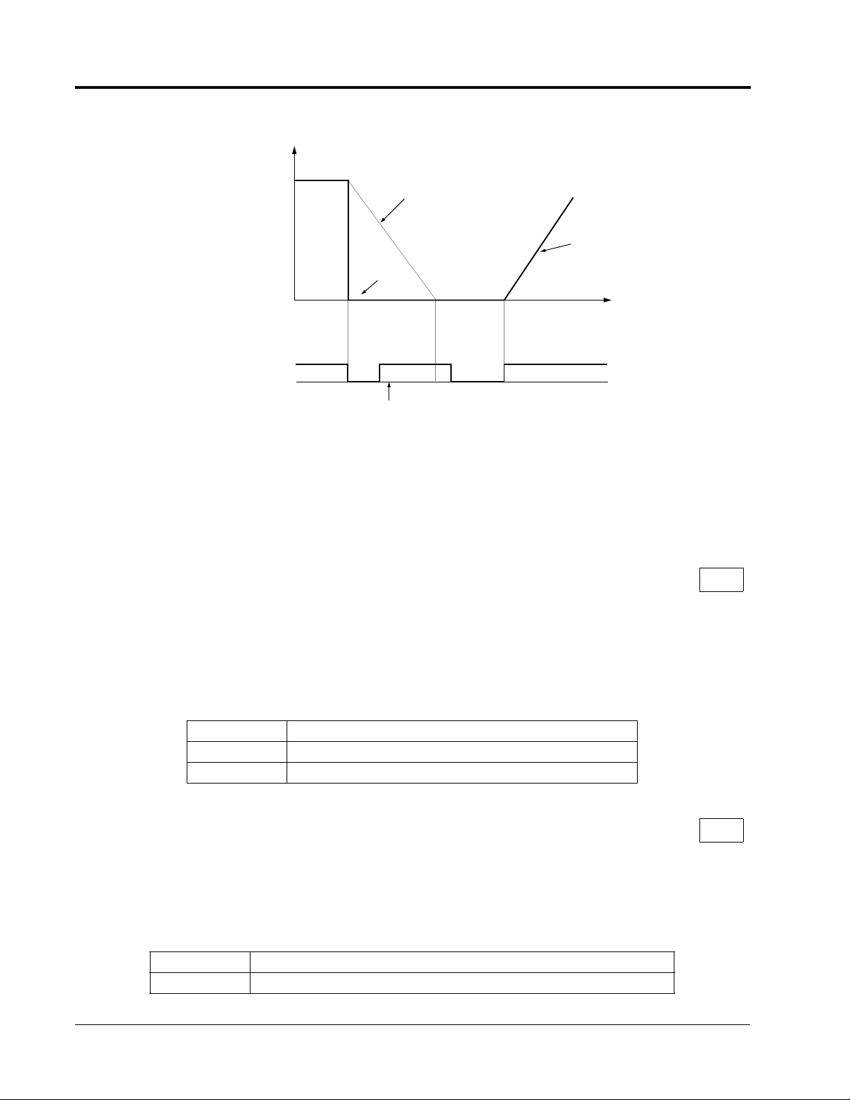
• Ramp to Stop (B1-03 = “0”)
Section B: Application Parameters
B1 Sequence
Output Frequency
Zero Speed Level
Factory Default 0.5Hz
Run Command
ON
OFF
Decel time 1 (C1-02)
Figure 1 Stopping Method - Ramp to Stop
Upon removal of the FWD (REV) run command, the motor decelerates at a rate
determined by the time set in deceleration time 1 (C1-02) and baseblocks upon
reaching the zero speed level (B2-01) or minimum speed (E1-08), whichever is
higher. If the deceleration time setting is too short or the load inertia is large, an overvoltage fault (OV) may occur during deceleration. In this case, increase the deceleration time or install an optional braking transistor and/or braking resistor (braking
transistors are provided as standard for units 230V 7.5kW and smaller, 460V 15kW
and smaller).
Braking torque: without braking resistor, approximately 5% of motor rated torque
with braking option, approximately 150% of motor rated torque
• Coast to Stop (B1-03 = “1”)
Output frequency
Run command
ON
Inverter output is shut OFF
when stop command is given.
OFF
Figure 2 Stopping Method - Coast to Stop
Upon removal of the FWD (REV) run command, the motor starts to coast. Upon reapplying the run command operation will resume after the minimum baseblock time
(L2-03) elapses.
Coast to Stop with Timer 1 (B1-03 = “3”) should be used to prohibit the inverter from
starting into a rotating motor. When setting B1-03=3, the deceleration time (C1-02) is
used as the timer during which operation is prohibited.
VS-616PS5 Programming Manual 11
Page 12
Section B: Application Parameters
B1 Sequence
• Coast to Stop with Timer 1 (B1-03 = “3”)
Output Frequency
Coasting
FWD (REV)
Run Command
Run Command Disabled
Decel Time 1
(C1-02)
Accel Time 1
(C1-01)
Time
ONONON
Figure 4 Stopping Method - Coast to Stop w/Timer
Upon removal of the run command, a new run command is blocked until the coast to
stop timer has elapsed (same as Decel 1). After the timer elapses, the user must
enter another run command for the inverter to begin acceleration. This stopping
method is disabled during flux vector control.
B1-04 Reverse Operation Enable/Disable B
Setting Range: 0 to 1
Factory Default: 0
A “reverse run disabled” setting does not allow a reverse run command from the control circuit terminal or the digital operator. This setting is used in applications where a
reverse run command is undesirable.
Setting Description
0 Reverse run is enabled (factory default).
1 Reverse run is disabled.
B1-05 Operation Selection at Zero Speed A
Select an operation mode to be used when the speed reference (analog input) drops
below the minimum speed setting (El -08).
Setting Description
0 E1-08 is ignored, run according to speed reference.
12 VS-616PS5 Programming Manual
Page 13

Section B: Application Parameters
B1 Sequence
Setting Description
1 Baseblock (factory default)- No output to motor
2 Run at minimum output speed (E1-08).
3 Zero-speed operation (internal speed reference is set to “0”)
B1-06 LOCAL/REMOTE Run Select A
This parameter determines how the inverter will function when switching from local to
remote operation when the external run command is applied.
Selection Description
0 Operation is disabled if the external run command is applied
prior to switching from local to remote. The run command
must be removed and re-applied to start operation.
1 Operation is enabled if the external run command is applied
prior to switching from local to remote.(factory default).
VS-616PS5 Programming Manual 13
Page 14

Section B: Application Parameters
B2 Servo Speed Level
B2 Zero Speed Level
.
B2-01 Zero-speed Level (Baseblock level) B
Setting Range: 0.0 to 20.0%
Factory Default: 0.5%
Sets the speed at which the inverter baseblocks upon deceleration. 20% equals 20%
of the maximum speed setting as entered in parameter E1-06.
The initial value is 0.5%. The units can be changed by O1-03.
14 VS-616PS5 Programming Manual
Page 15

Section B: Application Parameters
B3 Magnetic Pull-in
B3 Magnetic Pull-in
The magnetic pull-in (Synchronization) feature is used only during the PG orientation
auto-tuning process. During normal operation this function is not performed.
During PG Orientation Auto-Tuning, the following parameters are used to gradually
ramp up the motor current to a desired level to allow a “soft” rotor pole alignment.
Once the magnetic pull-in is completed, the PG Orientation feature is performed.
B3-02 Magnetic Pull-in Current A
Setting Range: 0 to 150%
Factory Default: 50%
The current level during initial magnetic pull-in is set in units of 1%.
A setting of 100% generates Motor rated current (E1-04). Increasing this value
increases the motor torque during the pull-in process.
B3-04 Current Ramp-up Time A
Setting Range: 0.0 to 5.0s
Factory Default: 1.0s.
Sets the rate at which the current is increased during the magnetic pull-in process.
Too short a setting will result in abrupt rotor movement.
VS-616PS5 Programming Manual 15
Page 16
Current Value
B3-04
B3-05
Section B: Application Parameters
B3 Magnetic Pull-in
B3-05 Magnetic Pull-in Time A
Setting Range: 0.0 to 5.0s
Factory Default: 1.0s
This parameter sets the time to allow the rotor to pull in (align) with the magnetic field
at initial excitation. Pull-in waiting time is set in units of 0.1s.
The current vs. time plot during the magnetic pull-in process is as follows:
B3-02
0 1 2
Operation Status B3-02 Adjustment B3-04 Adjustment B3-05Adjustment
Slow Start - Decrease set value Decrease set value
Insufficient torque, and
“STO” is output
Increase set value. - -
Time
16 VS-616PS5 Programming Manual
Page 17
Section B: Application Parameters
B4 Delay Timers
B4 Delay Timers
Use the inverter input (multifunction inputs) and output (multifunction outputs) in
place of an external timer. When a multi-function contact input (H1-XX = “18”) is
closed, a multi-function contact output (H2-XX = “12”) can be set to close after the
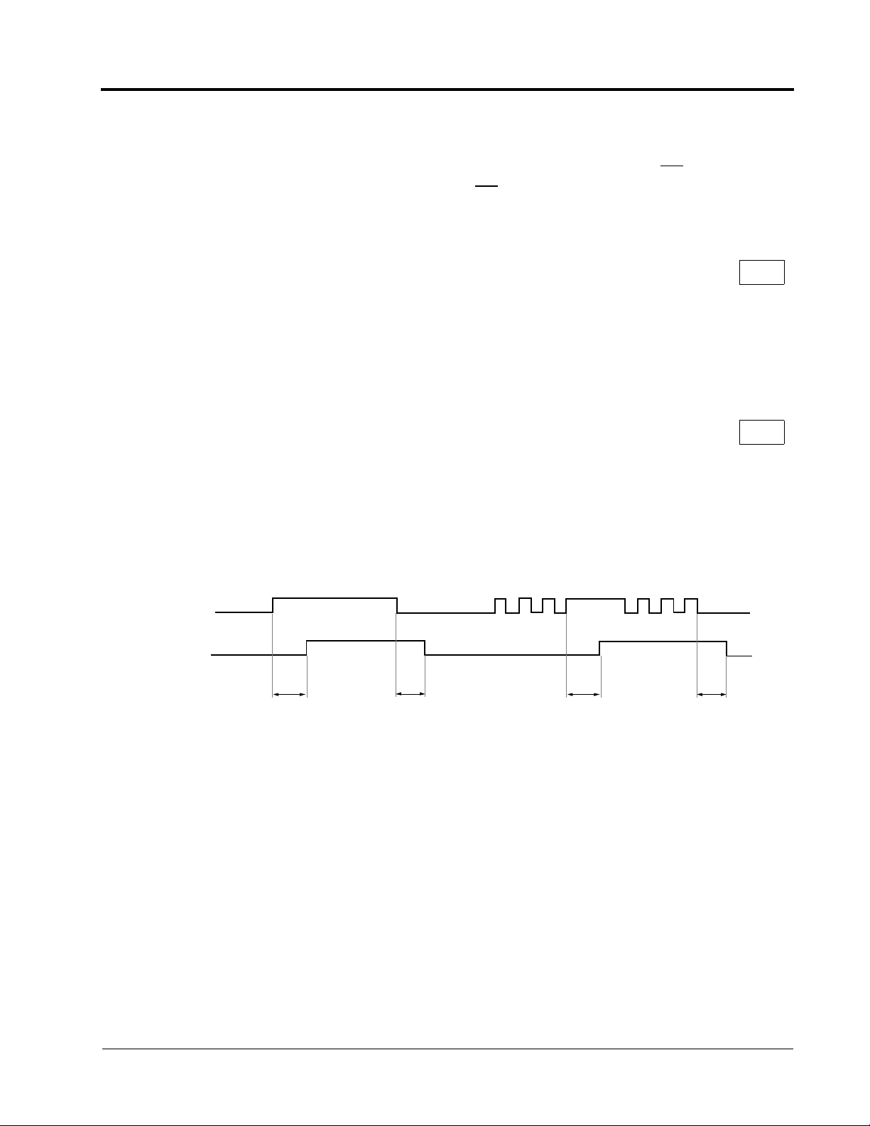
On-delay time (B4-01) has expired. This function operates independently of any concurrent inverter activity.
B4-01 On-delay Timer A
Setting Range: 0.0 to 300.0s
Factory Default: 0.0s
Sets the ON-delay time in units of 0.1 second. The multi-function input must be
“closed” for longer than the ON-delay timer for the multi-function output to close.
B4-02 Off-delay Timer A
Setting Range: 0.0 to 300.0s
Factory Default: 0.0s
Sets the OFF-delay time in units of 0.1 second. The multi-function input must be
“open” longer than the OFF-delay timer for the multi-function output to open.
Multi-function Contact
Input: Timer Function
Multi-function Contact
Output: Timer Function
B4-01
ON
ON
B4-02
ON ON ON
B4-01
ON
ON ON ON
ON
B4-02
Figure 8 Timing Diagram of Timer Function
VS-616PS5 Programming Manual 17
Page 18

Section B: Application Parameters
B5 PID Control
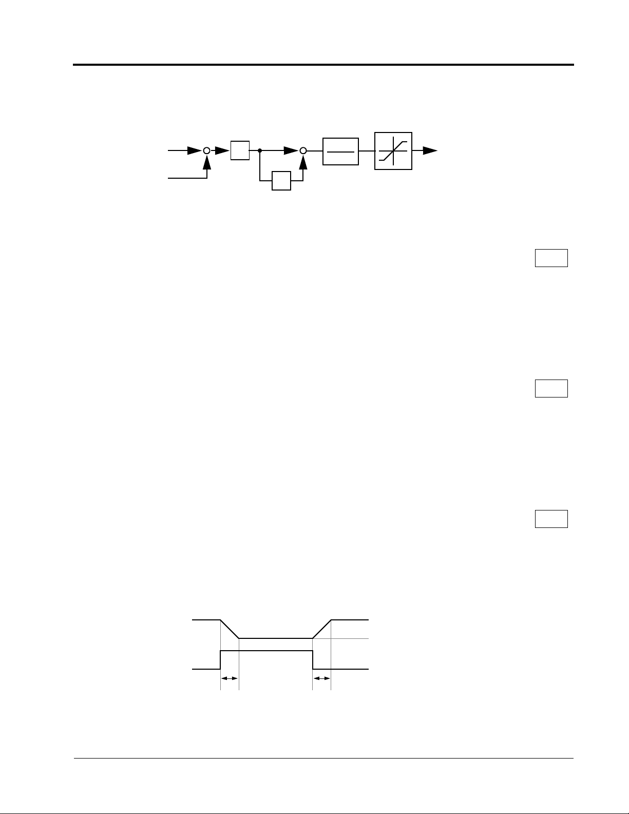
B5 PID Control
The Proportional, Integral, and Derivative (PID) control function provides closed-loop
control and regulation of a system variable such as temperature or pressure. A control signal based on the difference (or error) between a feedback signal and a desired
setpoint is produced. Integration and derivative calculations are then performed on
this signal, based upon the PID parameter settings (B5-01 to B5-08), to minimize
deviation, for precise control.
B5-01 PID Control Mode Selection A
To enable PID control, set PID control mode selection to “1” or “2”, according to the
description below. Also be sure to set terminal 16 function selection (H3-05) to PID
feedback (Set Value: “B”).
Setting Description
0 PID is disabled (factory default).
1 PID is enabled (deviation signal is put through derivative control).
2 PID operates with feed forward (feedback signal is put through derivative control).
Notes:
1. PID with feed forward applies control much quicker than normal PID, without waiting for the
deviation signal to build up.
2. A PID inverse feedback signal can be selected by inverting the settings for terminal 16 gain
and bias.
Then select the PID control intended value (setpoint) and detected value (feedback)
setpoint as follows:
Detected Value (Feedback)
Set the PID feedback value with the control circuit terminal 16 voltage signal (0 to
10V, -10 to 10V) or multi-step speed parameters H1-03 to H1-06.
Control circuit terminal 16 voltage signal:
Set reference selection (B1-01) to “1” and set H3-05 = “B”.
Multi-step speed parameters via multifunction inputs (H1-01 to H1-06):
Set reference selection (B1-01) to “0.”
Set multifunction inputs to (H1-01 to H1-06) set value 3,4 and/or 5.
(allows combination of multi-step speed references and jog frequency reference
as entered in parameter D1-01 thru D1-09)
Intended Value (Setpoint)
The control circuit terminal 14 current signal (4 to 20mA) or voltage signals (0 to 10V,
-10 to +10V) can be used to set the PID setpoint value.
Control circuit terminal 14 accepts 4-20 MA current signal:
Set terminal 14 signal selection (H3-08) to “2.”
18 VS-616PS5 Programming Manual
Page 19
Section B: Application Parameters
B5 PID Control
Control circuit terminal 14 accepts voltage signal:
Set terminal 14 signal selection (H3-08) to “0” for 0-10 VDC input signal or “1” for 10 to 10 VDC input signal. The J1 jumper must also be cut to set-up terminal 14
to accept a voltage signal.
B5-02
B5-01
1
+
2
+
P
0
Frequency
Reference
I
B5-03
D
B5-05
Limit
B5-04
1
2
B5-06
++
Limit
+
Offset
B5-07
B5-08
Output
Delay Time
1 or 2
B5-01
Intended
Value
Detected
Value
H3-06
Feedback
Calibration
Gain
D
B5-05
(Deviation) -
+
B5-01
Figure 9 PID Control Block Diagram
Notes:
1. I value is reset to ”0” when operation stops.
2. The upper limit of the I value can be set by parameter B5-04.
Increase the value of parameter B5-04 to upgrade control capability by
integration. If the control system is unstable and it cannot be stopped by
adjusting the integral time, output delay time, etc., decrease the set value
of parameter B5-04.
3. PID control can be canceled by a multi-function contact input signal.
By setting any of parameters H1-01 to H1-06 to “19” and by closing the
contact during running PID control is disabled and the intended value signal itself is used as a frequency reference signal.
B5-02 PID Control Proportional Gain A
Setting Range: 0.00 to 25.00
Factory Default: 1.00
The proportional gain is the value by which the deviation signal is multiplied to generate a new frequency reference. Too high a setting will result in oscillations (instability).
Too low a setting will result in a sluggish response.
VS-616PS5 Programming Manual 19
Page 20

Section B: Application Parameters
B5 PID Control
B5-03 PID Control Integral Time A
Setting Range: 0.00 to 360.0s
Factory Default: 1.00s
The integral calculation sums the deviation over time which forces the deviation to
become zero. Thus, the feedback will match the desired setpoint. The integral time
determines how quickly the integral gain increase is added to the control loop. Too
high a setting will result in slow response. Too low a setting may result in rapid oscillations (instability).
B5-04 PID Control Integral Limit A
Setting Range: 0.0 to 100.0%
Factory Default: 100.0%
The integral limit is used to limit the range of the integral term. In some applications it
may be desirable to limit the integral term to improve system response. Otherwise,
the integral value may become large and overshoots may result when the integral
value takes a long time to integrate in the opposite direction. This value is set as a
percentage of maximum motor speed (E1-06).
B5-05 PID Control Derivative Time A
Setting Range: 0.00 to 10.00s
Factory Default: 0.00s
The derivative calculation attempts to control the remaining overshoot left over after
the proportion and integral calculations. If the system is approaching the intended
value very rapidly, the derivative control produces a strong braking action to prevent
overshoot. If the system is already stable with very little deviation change, derivative
control has very little effect. The derivative time is used to dampen oscillations and
reduce overshoot, thus improving stability. Setting the derivative time to a larger
number produces more braking action in the control system.
B5-06 PID Control Limit A
Setting Range: 0.0 to 100.0%
Factory Default: 100.0%
The PID limit places a limit on the PID signal output, limiting the output frequency reference. Normally this is set to 100% to allow unrestrained operation of the PID function. This value is set as a percentage of maximum motor speed (E1-06).
20 VS-616PS5 Programming Manual
Page 21

Section B: Application Parameters
B5 PID Control
B5-07 PID Control Offset A
Setting Range: ±100.0%
Factory Default: 0.0%
The PID offset adds a bias to the calculated PID value.
B5-08 PID Control Output Primary Delay Time A
Setting Range: 0.00 to 10.00s
Factory Default: 0.00s
The output delay time builds in a delay to changes in the calculated PID value, which
can prevent oscillations and improve stability. Use the PID Delay Time when transients occur in the system and it is undesirable to have the PID respond.
Parameters B5-04 thru B5-08 are preset at the factory to optimum values for most
applications, and hence, do not need to be changed.
When tuning a system, first increase the proportional gain until oscillations occur.
Then, reduce the proportional gain slightly until the oscillations stop. Next, reduce the
integral time slowly until oscillations begin. Then, increase the integral time slowly so
that the oscillations cease. Test the system under all conditions, observe the stability
and verify that the desired operation is generated. Fine tune the proportional and integral times, along with any other PID parameter as needed.
VS-616PS5 Programming Manual 21
Page 22

Section B: Application Parameters
B6 Reference Hold
B6 Reference Hold
The reference hold or dwell function is used to temporarily hold the output frequency
at a set reference, for a set time, during the acceleration and deceleration process.
Use this function when driving a permanent magnet motor, or a motor with a heavy
starting load. The pause in acceleration allows the magnets in a permanent magnet
motor to synchronize with the stator field of the motor, thus reducing traditionally high
starting current.
B6-01 Dwell Reference at Start A
Setting Range: 0.00 to 100.00%
Factory Default: 0.00%
Sets the dwell frequency reference during acceleration in units of 0.01%.
B6-02 Dwell Time at Start A
Setting Range: 0.0 to 10.0s
Factory Default: 0.0s
Sets the amount of time that the frequency reference “dwells” during acceleration in
units of 0.1s.
B6-03 Dwell Reference at Stop A
Setting Range: 0.00 to 100.00%
Factory Default: 0.00%
Sets the dwell frequency reference during deceleration in units of 0.01%.
B6-04 Dwell Time at Stop A
Setting Range: 0.0 to 10.0s
Factory Default: 0.0s
Sets the amount of time that the frequency reference “dwells” during deceleration in
units of 0.1s.
22 VS-616PS5 Programming Manual
Page 23

Section B: Application Parameters
B7 DROOP Control
B7 Droop Control
Droop Control is a function that allows the speed of a motor to decrease in proportion
to load torque. This can be used to insure load sharing between drives on multiple
drive systems.
B7-01 Droop Capacity A
Range:0.0 to 100.0%
Factory Default: 0.0%
Droop amount (%)
=
B701–()
------------------------- %
100
x 100
A setting of 100% allows the speed to drop 100% of the maximum speed value
(when the torque is 100%).
Droop response time is set with parameter B7-02.
B7-02 Droop Delay Time A
Setting Range: 0.00 to 1.00s
Factory Default: 0.10s
When B7-02 is decreased, drooping response becomes quicker, but the motor
hunts more easily.
Torque
Load
Motor
Speed
63%
B7-02
Droop Amount (B7-01)
= Torque (%) x B7-01
VS-616PS5 Programming Manual 23
Page 24
Section C: Tuning Parameters
C1 Accel/Decel
C Tuning Parameters
C1 Accel/Decel
C1-01 Acceleration Time 1 Q
C1-02 Deceleration Time 1 Q
C1-03 Acceleration Time 2 B
C1-04 Deceleration Time 2 B
C1-05 Acceleration Time 3 A
C1-06 Deceleration Time 3 A
C1-07 Acceleration Time 4 A
C1-08 Deceleration Time 4 A
Setting Range: 0.00 to 6000.0s
Factory Default: 10.0s
The acceleration parameters set the time necessary for the output speed to accelerate from 0 to the maximum Speed (E1-06). Deceleration parameters set the time
needed for the output Speed to decelerate from the maximum speed to 0. .
Accel Time 1
(C1-01)
Output
Frequency
FWD (REV) Run Command
Accel/Decel Time Selection 1
(Terminals 3 to 8, Setting = “7”)
Accel/Decel Time Selection 2
(Terminals 3 to 8, Setting = “1A”)
* When “ramp to stop” is selected (B1-03 = “0”)
Decel Time 1* (C1-02)
ON OFF ON
Figure 13 Timing Diagram of Accel/Decel Time Adjustment
Accel Time 2 (C1-03)
ON
Decel Time 2*
(C1-04)
Decel Time 1*
(C1-02)
Accel Time 3
(C1-05)
ON OFF ON
OFF
Decel Time 3* (C1-06)
Accel Time 4 (C1-07)
ON
ON
Decel Time 4*
(C1-08)
Decel Time 1*
(C1-02)
Time
Use the multifunction inputs to select up to four accel/decel times. When any of the
multi-function contact input selections (H1-01 to H1-06) are set to “7”and “1A”, up to
four accel/decel times can then be selected by opening or closing the appropriate
accel/decel time selection commands (terminals 3 to 8).
24 VS-616PS5 Programming Manual
Page 25

Section C: Tuning Parameters
C1 Accel/Decel
.
Accel/decel Time Selection 1
Multi-function Input
Setting = “7”
Open or not set Open or not set C1-01 C1-02
Closed Open or not set C1-03 C1-04
Open or not set Closed C1-05 C1-06
Closed Closed C1-07 C1-08
Accel/decel Time Selection 2
Multi-function Input
Setting = “1A”
Accel Time Decel Time
C1-09 Fast-stop Time B
Setting Range: 0.00 to 6000.0s
Factory Default: 10.0s
When a Multi-function contact input is set to fast-stop command (setting = “15”), and
the contact closes the fast stop feature is executed.
It may be necessary to install a braking unit to achieve the desired stopping rate and
eliminate over-voltage from occurring.
C1-10 Accel/Decel Time Setting Units A
Setting Description
0 Accel/decel time (C1-01 to C1-09) setting range is in units of 0.01s.
Accel/decel time setting range: 0.00 to 600.00s
1 Accel/decel time (C1-01 to C1-09) setting range is in units of 0.1 second.
Accel/decel time setting range: 0.0 to 6000.0s (factory default).
If any of the parameters C1-01 to C1-09 is set to 600.1 seconds or more, C1-10 cannot be set to “0.”
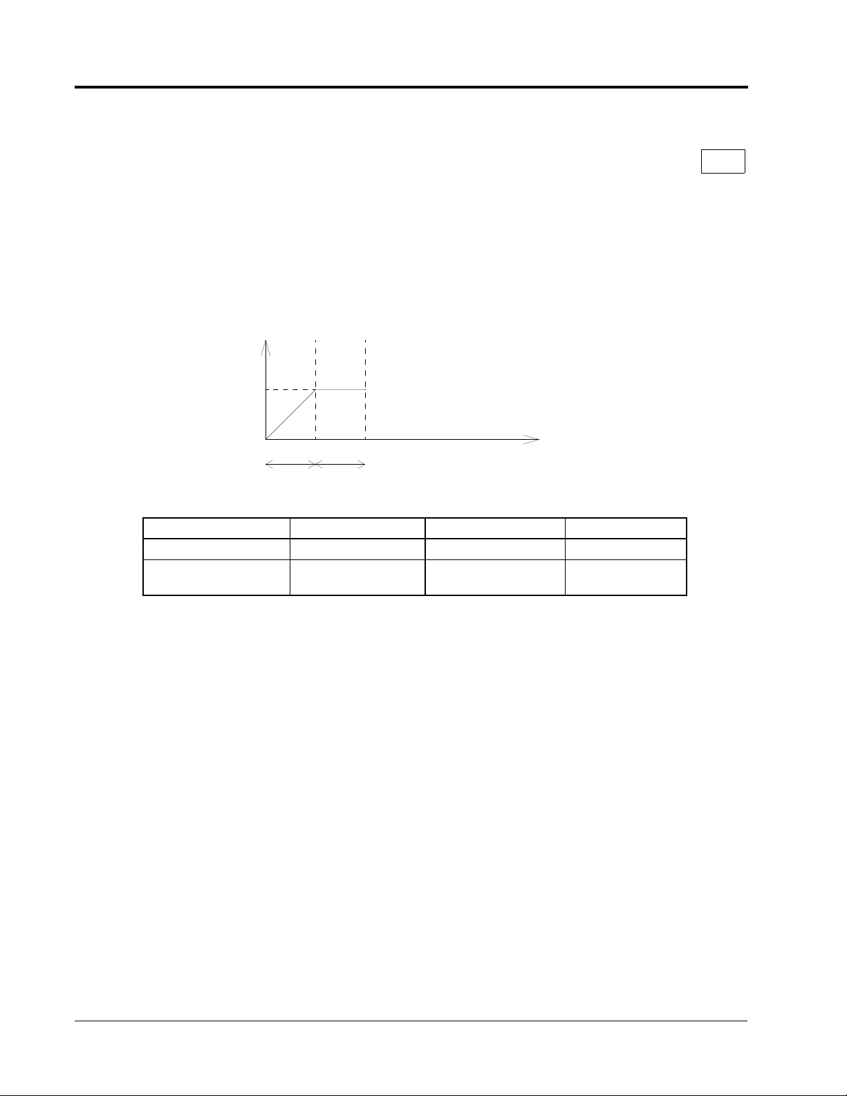
C1-11 Automatic Accel/Decel Time Switching Speed Level A
Setting Range: 0.0 to 100.0%
Factory Default: 0.0%
Accel/decel times can be changed automatically, without using the multi-function contact inputs. This feature is active anytime C1-11 is not equal to 0.
Use accel/decel times set in parameters C1-01 and C1-02 when output frequency ≥
C1-11.
Use accel/decel times set in parameters C1-07 and C1-08 when output frequency <
C1-11.
Multi-function contact inputs which are set for accel/decel selection have priority over
VS-616PS5 Programming Manual 25
Page 26

Section C: Tuning Parameters
C1 Accel/Decel
the automatic change of accel/decel.
Output Frequency
Accel/Decel Switching Level
(C1-11)
C1-07
C1-01 C1-02 C1-08
Figure 14 Accel/Decel Switching Level Adjustment
26 VS-616PS5 Programming Manual
Page 27

Section C: Tuning Parameters
C2 PG Origin Pulse Compensation
C2 PG Origin Pulse Compensation
C2-13 PG Origin Pulse Compensation Value Q
Setting Range: ±180°
Indicates the angular displacement between the magnetic pole and the marker pulse
from the hall sensor or encoder feedback devices. This value is used to control the
commutation to insure optimum performance.
This value is automatically set when performing PG origin auto-tuning.
Do not change after setting.
This value is not initialized at initialization.
VS-616PS5 Programming Manual 27
Page 28

Section C: Tuning Parameters
C3 Voltage Limit Control
C3 Voltage Limit Control
C3-05 Voltage Limit Control Selection A
This parameter sets the voltage limit control.
Set Value Description
0 •Voltage limitation control is not performed (fac-
tory default).
1 •Voltage limitation control is performed limits the
output voltage to 230 (460) by reducing the d-axis
current level.
28 VS-616PS5 Programming Manual
Page 29
C5 ASR Tuning
Proportional Gain According to Motor Speed
The Automatic Speed Regulator (ASR) provides closed loop motor speed control so
that optimum performance during changes in motor speed or load can be achieved.
Section C: Tuning Parameters
C5 ASR Tuning
Torque Limit
Secondary Current Reference
L7-01 ~ L7-04
Speed Reference
Speed Feedback
+
C5-01, C5-03
-
P
I
C5-02, C5-04
+
+
1
1 + ST
C5-05
Figure 20 ASR Block Diagram (Flux Vector Control)
C5-01 ASR Proportional Gain 1 B
Setting Range: 0.00 to 300.00
Factory Default: 5.00
The ASR proportional gain 1 adjusts the speed in response to the speed deviation
signal. Speed response increases as the proportional gain is increased. However,
the load may become unstable if the ASR proportional gain is set too high.
C5-02 ASR Integral Time 1 B
Setting Range: 0.000 to 10.000s
Factory Default: 0.500s
The ASR integral time 1 adjusts the inverter’s response time to changes in load.
Response increases as the integral time is decreased. However, the load may
become unstable if the ASR integral time is set too low.
C5-03 ASR Proportional Gain 2 B
Setting Range: 0.00 to 300.00
Factory Default: 5.00
The ASR proportional gain 2 is an additional proportional gain adjustment that can be
enabled by a multi-function contact input (H1-XX = “77”).
(see Figure 22)
C5-03 Proportional Gain
Multi-function Input
(H1-XX = “77”)
ON
OFF
C5-02
OFF
ON
C5-02
Figure 21 ASR Multi-function Input Timing Diagram
VS-616PS5 Programming Manual 29
Page 30

Section C: Tuning Parameters
C5 ASR Tuning
C5-04 ASR Integral Time 2 B
Setting Range: 0.000 to 10.000s
Factory Default: 0.500s
The ASR integral time 2 is an additional integral time adjustment.
C5-05 ASR Output Primary Delay Time A
Setting Range: 0.000 to 0.500s
Factory Default: 0.004s
Mechanical backlash in an application causes secondary current (I2) reference variations in the motor’s rotor. This condition can undesirably limit the adjustment of ASR
parameters. The output delay time constant is used to control these secondary current (I2) reference variations.
C5-06 ASR Switching Speed Level A
Setting Range: 0.00 to 100.00%
Factory Default: 0.00%
Sets speed at which C5-01 and C5-02 are achieved. When C5-06 is set to any setting other than 0, both sets of proportional and integral values are used (See Figure
22).
C5-01
C5-02
C5-03
P gain · I time
0
C5-06
C5-04
f
FB
Motor Speed
P · N
fFB =
120
where . . .
P = Number of Motor Poles
N = Motor RPM
* When C5-06 =”0”, proportional gain 1 (C5-01)
and integral time 1 (C5-02) are selected.
Figure 22 ASR Switching Speed Level
Notes:
1. When C5-06 =” 0”, proportional gain 1 (C5-01) and integral time 1 (C5-02) are selected.
C5-07 ASR P Gain at Start A
Setting Range: 0.00 to 300.00
Factory Default: 5.00
This parameter sets the ASR P gain applied at magnetic pole pull-in. It is set to a
unit of 0.01.
30 VS-616PS5 Programming Manual
Page 31

Section C: Tuning Parameters
C6 Carrier Frequency
C6 Carrier Frequency
This function sets the inverter output transistor switching frequency (carrier frequency). Increase the carrier frequency to reduce motor noise and decrease it to
reduce leakage current. When increasing the carrier frequency above the factory
default values, current derating is necessary.
C6-02 Carrier Frequency Upper Limit A
Factory Settings:
230 Volt Models
Model Number Carrier Frequency
PS5U20P4
PS5U20P7
PS5U21P5
PS5U22P2
PS5U23P7
PS5U25P5
PS5U27P5
PS5U2011
PS5U2015
8kHz
460 Volt Models
Model Number Carrier Frequency
PS5U40P4
PS5U40P7
PS5U41P5
PS5U42P2
PS5U43P7
PS5U45P5
PS5U47P5
PS5U4011
PS5U4015
PS5U4018
PS5U4022
PS5U4030
PS5U4037
PS5U4045
PS5U4055
PS5U4075
PS5U4110
PS5U4160
8kHz
4kHz
VS-616PS5 Programming Manual 31
Page 32

Section C: Tuning Parameters
C6 Carrier Frequency
460 Volt Models
Model Number Carrier Frequency
PS5U4185
2kHzPS5U4220
PS5U4300
Pulse
Reference
1/100
C6-14
Speed Reference
C6-13
32 VS-616PS5 Programming Manual
Page 33

Section C: Tuning Parameters
C6 Carrier Frequency
C6-13 Pulse Reference Ratio Denominator Value A
Setting Range: 0 - 1000
Factory Default: 0
Sets the denominator portion of the pulse reference multiplication block. Used when
B1-02=6 (Pulse Train reference mode).
C6-14 Pulse Reference Ratio Numerator Value A
Setting Range: 0 - 1000
Factory Default: 0
Sets the numerator portion of the pulse reference multiplication block. Used when
B1-02=6 (Pulse Train reference mode).
Pulse
Reference
1/100
C6-14
Speed Reference
C6-13
VS-616PS5 Programming Manual 33
Page 34

Section C: Tuning Parameters
C7 S-Curve Accel/Decel
C7 S-Curve Accel/Decel
An S-curve pattern is used to reduce shock and provide smooth transitions during machine
acceleration and deceleration. S-curve characteristic time is the time it takes to reach the set
accel/decel rate during a speed change.
C7-01 S-Curve Time at Acceleration Start A
C7-02 S-Curve Time at Acceleration End A
C7-03 S-Curve Time at Deceleration Start A
C7-04 S-Curve Time at Deceleration End A
Setting Range: 0.00 to 2.50s
Factory Default: 0.00s
.
Frequency Reference
Output Frequency
S-curve Characteristic
Time (Tsc)
Output Frequency
Time
Figure 15 S-curve Characteristic Timing Diagram
The following figure shows FWD/REV run switching with deceleration to stop.
FWD Run Command
REV Run Command
C7-02
Output Frequency
C7-01
C7-03
C7-04
DC Injection Braking
Time at Stop
B2-04
C7-01
C7-02 C7-03
C7-04
Figure 16 S-curve Characteristics - FWD/REV Operation
Time to accelerate from the minimum frequency
to the maximum frequency (total acceleration)
= C1-XX + (C7-01 + C7-02)/2
34 VS-616PS5 Programming Manual
Page 35

Section D: Reference Parameters
D1 Preset References
D Reference Parameters
D1 Preset References
D1-01 Preset Reference 1 Q
D1-02 Preset Reference 2 Q
D1-03 Preset Reference 3 Q
D1-04 Preset Reference 4 Q
D1-05 Preset Reference 5 B
D1-06 Preset Reference 6 B
D1-07 Preset Reference 7 B
D1-08 Preset Reference 8 B
Setting Range: 0.00 to 100.00%
Factory Default: 0.00%
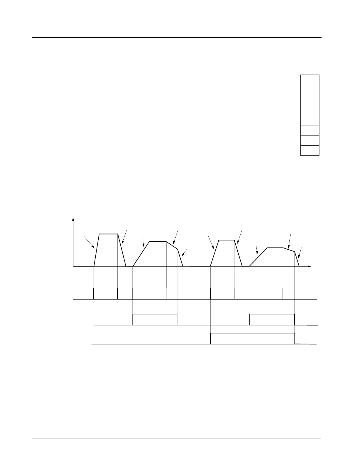
Up to 9 preset speed references (including jog) with the multi-function contact input
function selections. When using the multi-step speed references, set the reference
selection (B1-01) to “0,” and set terminal 16 selection (H3-05) to “1F.” See the following table for programming preset speed references.
Terminal 5
H1-03 = “3”
Open Open Open Open Speed Reference 1 - Set Reference Source
Closed Open Open Open Speed Reference 2 - Set Terminal 16 Selection
Open Closed Open Open Speed Reference 3
Closed Closed Open Open Speed Reference 4
Open Open Closed Open Speed Reference 5
Closed Open Closed Open Speed Reference 6
Open Closed Closed Open Speed Reference 7
Closed Closed Closed Open Speed Reference 8
Closed Closed Closed Closed Jog Speed Reference
Terminal 6
H1-04 = “4”
Terminal 7
H1-05 = “5”
Terminal 8
H1-06 = “6”
Speed Reference
(B1-01) to “0.”
(H3-05) to “1F.”
D1-09 Jog Frequency Reference B
Setting Range: 0.00 to 100.00%
Factory Default: 10.00%
The jog frequency reference can be set in this parameter. Depress the JOG key on
the digital operator, or close terminal 7 to use this function. The jog command always
has priority over other reference commands. When using the multi-step speed references as indicated in the table above, change the jog command from terminal 7 to
terminal 8 (H1-06 = “6”). Selecting the jog frequency reference via a multifunction
input selects the jog frequency reference only. A separate run command also needs
to be applied to start the unit.
VS-616PS5 Programming Manual 35
Page 36

Section D: Reference Parameters
D1 Reference Limits
Frequency
Reference
D1-01
10.0Hz
FWD (REV) Run/Stop
D1-02
20.0Hz
D1-03
30.0Hz
D1-04
40.0Hz
D1-05
45.0Hz
ON
D1-06
50.0Hz
D1-08
60.0Hz
D1-07
55.0Hz
D1-09
6.0Hz
Time
Multi-step Speed Ref. 1
(Terminal 5)
Multi-step Speed Ref. 2
(Terminal 6)
Multi-step Speed Ref. 3
(Terminal 7)
Jog Ref.
(Terminal 8)
ON
ON
ON
ON ON
ON
ON
ON
Figure 24 Multi-step Speed Operation - Timing Diagram
Note: Setting units for D1-01 to D1-09 are dependent upon the setting of digital operator display mode
(O1-03). Possible setting units include Hz, percentage, RPM, or engineering units. See section
O1, Monitor Selection, for more details.
36 VS-616PS5 Programming Manual
Page 37

Section D: Reference Parameters
D2 Reference Limits
D2 Reference Limits
D2-01 Speed Reference Upper Limit B
Setting Range: 0.0 to 110.0%
Factory Default: 100.0%
The speed reference upper limit is set as a percentage of the maximum output speed
(E1-06). Limits the maximum output speed of the motor.
D2-02 Speed Reference Lower Limit B
Setting Range: 0.0 to 100.0%
Factory Default: 0.0%
The speed reference lower limit is set as a percentage of the maximum output speed
(E1-06). When a run command is input and the speed reference is less than the
lower limit, operation continues at the speed reference lower limit. However, when
the lower limit is set to less than the minimum output speed (E1-08), operation discontinues.
%
100
Internal
Speed
Reference
D2-02
0
Set Frequency Reference
E1-06
D2-01
Hz
Figure 25 Setting Frequency Upper and Lower Limits
VS-616PS5 Programming Manual 37
Page 38

Section D: Reference Parameters
D3 Jump Frequencies
D3 Jump Frequencies
D3-01 Jump Speed Reference 1 A
D3-02 Jump Speed Reference 2 A
D3-03 Jump Speed Reference 3 A
Setting Range: 0.0 to 200.0%
Factory Default: 0.0%
D3-04 Jump Speed Reference Bandwidth A
Setting Range: 0.0 to 200.0%
Factory Default: 1.0%
These functions allow the prohibition or “jumping” of critical Speeds so that the motor
can operate without resonant vibrations caused by some machine systems. They are
also used for dead band controls. Setting the value to 0.0% disables each function.
Output
Frequency
%
D3-02
D3-01
Set Frequency Reference
D3-03
D3-04
D3-04
Figure 26 Jump Frequencies
D3-04
%
38 VS-616PS5 Programming Manual
Page 39

D4 Reference Memory (Memorize Last Reference)
D4 Reference Memory (Memorize Last Reference)
Section D: Reference Parameters
D4-01 Reference Memory Selection - (Up/Down or Accel/
Decel Hold Feature)
Selects whether the reference memorization feature during, Up/Down or Accel/Decel
Hold operation is stored when operation is stopped (when power is removed or when
the run command is cancelled or overridden).
Setting Description
0 Reference memorization during Up/Down or Accel/Decel Hold operation not retained. If a
stop command is given or if power is removed, the frequency reference is reset to 0Hz. If
the inverter is decelerating when the run command is restored, operation resumes at the
frequency reference which the inverter has ramped down to (factory default).
1 Reference memorization during an Up/Down or Accel/Decel hold operation is retained. If a
stop command is given, or if power is removed, operation resumes at the held frequency
reference when run command is restored.
Note: Up/Down operation is set using the multi-function contact input function selections (H1-01 to H1-
06, setting = “10” and “11”). Accel/Decel Hold operation is set using multi-function contact input
function selections (H1-01 to H1-06, setting = “A”). See section H1, Digital Inputs, for more
information.
A
VS-616PS5 Programming Manual 39
Page 40

Section D: Reference Parameters
D5 Torque Control
D5 Torque Control
D5-01 Torque Control Selection A
Select either speed and torque control.
Setting Description
0 Speed control enabled with torque limit (factory default)
1 Torque control enabled with speed limit
Speed/torque control selection can also be made by using a multi-function contact
input function selection (H1-XX = “71”). When using a multifunction contact input to
switch between speed and torque control, set D5-01 = “0”.
D5-02 Torque Limit Primary Delay Time A
Setting Range: 0 to 1000ms
Factory Default: 0ms
Sets delay time constant for torque reference input in the torque control mode, in
units of 1ms. This can be used to filter (smooth) a noisy/rapidly fluctuating torque reference signal so that abrupt torque changes do not occur.
D5-03 Speed Limit Input Selection A
Select speed limit location in the torque control mode.
Setting Description
1 Speed limit is the analog speed reference set by
terminal 13 or 14 (factory default).
2 Speed limit is the digital value set by D5-04.
D5-04 Speed Limit Value A
Setting Range: ±120%
Factory Default: 0%
Sets the speed limit value in the torque control mode as a percentage of the maximum output frequency. Used when D5-03 = “2.”
D5-05 Speed Limit Bias A
Setting Range: 0 to 120%
Factory Default: 5%
Sets the speed limit bias value in the torque control mode as a percentage of the
maximum output frequency. See “Torque Control Operation” description on following
page.
40 VS-616PS5 Programming Manual
Page 41

Section D: Reference Parameters
D5 Torque Control
D5-06 Speed/Torque Control Changeover Delay Timer A
Setting Range: 0 to 1000ms
Factory Default: 50ms
When using a multifunction input to switch between speed and torque mode, D5-06
can be used to allow the analog signals to be modified in preparation for the newly
selected mode.
Upon a change in command (Speed/Torque) the analog input values are retained for
the time set in D5-06 so the analog signals can be changed to accommodate the new
mode. After the D5-06 time elapses the new analog signals are accepted.
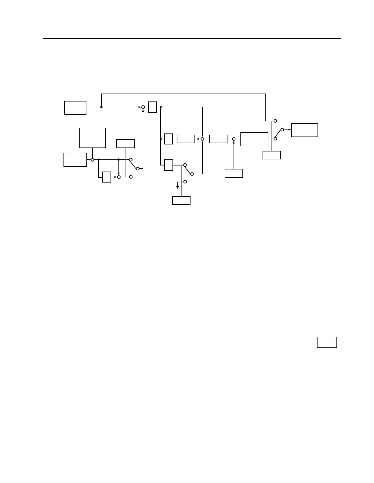
Torque Control Operation
To select torque control, set torque selection (D5-01) to “1,” or close the multi-function contact input set to speed/torque control (H1-XX = “71”) and set terminal 16 function selection to torque reference (H3-05 = “13”).
Torque
Compensation
Torque
Reference
Speed Limit
*2
Torque Limit
+
1
1 + ST
T = D5-02
*1
SFS
Motor Speed
(D5-05)
Speed
Limiting
Circuit
+
+
Iq
Figure 27 Torque Control Block Diagram
*1: When speed limit selection (D5-03) is set to “1,” the master frequency reference input from ter-
minal 13 or 14 becomes the speed limit; when speed limit selection (D5-03) is set to “2,” the set
value of D5-04 becomes the speed limit.
*2: When terminal 14 function selection is set to torque compensation (H3-09 = “14”), the terminal l4
set value can be used as the torque compensation value.
When torque reference > 0 and speed limit > 0 (winder application sequence), the following sequence is activated:
• When [-1 × speed limit bias (D5-05)] < motor speed (%) < [speed limit + D5-05],
torque control is activated using the set torque reference.
• When motor speed > [speed limit + D5-05], speed limiting circuit outputs a negative torque reference to prevent the motor speed from increasing.
• When motor speed < [-l × D5-05], the speed limiting circuit outputs a positive
torque reference to prevent the motor speed from increasing in the reverse direction.
VS-616PS5 Programming Manual 41
Page 42

Torque
Torque
Torque
Section D: Reference Parameters
D5 Torque Control
Therefore, when torque reference > 0 and speed limit (%) > 0, the torque control
range is:
[-l × D5-05] < motor speed < [speed limit + D5-05]
Refer to the following table for more details on the relationship between torque reference, speed limit, and motor speed.
Configuration
Winder Control Unwinder Control
Line Direction
TN
T
N
Line Direction
Direction of Motor
Rotation
Refer-
ence
Polarity
Torque
Refer-
ence
(TREF)
Speed
Limit
(NLIM)
Torque Profile
M
Motor
M
Motor
Forward Reverse Forward Reverse
+ - - +
+ - + -
Torque
Torque
Limit
D5-05
TREF
0
NLIM
Speed
Limit
Torque
Limit
NLIM
TREF
Torque
D5-05
0
Speed
Torque
Limit
D5-05
Torque
0
NLIM
Speed
Limit
Torque
Limit
Torque
TREF
NLIM
D5-05
0
Speed
Limit
Speed/Torque Control Switching
• Speed control or torque control can be selected “on the fly” by using the multifunction input speed/torque control selection command (H1-XX = “71”).
Terminal No. Parameter No. Setting Description
8 H1-06 71 Speed/torque control selection
13 B1-01
D5-03
1
1
Frequency reference selection (terminals 13, 14)
Speed limit selection (terminals 13, 14)
16 H3-05 13 Torque reference
42 VS-616PS5 Programming Manual
Page 43

Section D: Reference Parameters
D5 Torque Control
Speed/Torque
Selection Command
(Terminal 8 Input)
Run Command
Control Method
Terminal 13 Input
Terminal 16 Input
Sequence
STOP
OFF ON OFF ON
RUN
Speed Control Torque Control
Speed Reference Speed Limit
Torque Limit Torque Reference
Speed Control Torque Control Speed Control (decel to stop)
Speed Reference Speed Limit
Torque Limit Torque Reference
• ‚ • ‚ ƒ
Figure 28 Speed/Torque Control Selection Timing Diagram
Sequence Description
• When the speed/torque control selection contact is OPEN, speed control is activated:
• Speed reference during speed control depends on the frequency reference
selection (B1-01) setting. To use terminal 13 or 14 as the master frequency reference, set Bl-0l to “l.”
• Torque limit during speed control is the smaller of the absolute value of terminal
16 torque limit (H3-05 = 13), or the values set in the torque limit parameters (L7-
01 to L7-04).
• When a stop command is given during speed control, speed control is maintained and the smaller of the absolute value of terminal l6 torque limit, or the values set in the torque limit parameters (L7-01 to L7-04), is used as the torque
limit. Then the motor decelerates to stop.
‚ When the speed/torque control selection contact is CLOSED, torque control is
activated:
• Speed limit during torque control is:
• the master frequency reference at terminal 13 or 14 when speed limit selection
(D5-03) is set to “1”
• the speed limit value (D5-04) when D5-03 = “2,” regardless of the frequency reference selection (B1-01) setting.
• During torque control, the terminal 16 analog input value becomes the torque
reference.
ƒ By giving a stop command during torque control, operation changes to speed control automatically, and the motor decelerates to stop. The torque limit during deceleration to stop becomes the values set in the torque limit parameters (L7-01 to L7-04).
Note:The control mode actually changes after the speed/torque control selection command changes and
after the reference delay timer (D5-06) elapses. The terminal 13 speed reference/speed limit and the
terminal 16 torque limit/torque reference are stored in the inverter until the time set to D5-06 passes.
VS-616PS5 Programming Manual 43
Page 44

Section E: Motor Parameters
E1 V/f Pattern
E Motor Parameters
E1 Motor Constant
E1-01 Inverter Input Voltage Setting Q
Setting Range: 180 to 230V (360 to 460V)
Factory Default: 230V (460V)
Set E1-01 to the nominal expected line voltage (exact setting is not required)
This setting adjusts the overvoltage level, the braking transistor turn on level, and the
stall prevention level during deceleration.
Inverter
Voltage
230 150 - 255 400V 380V 380V 375V 380V
460 >400 800V 760V 760V 750V 760V
460 <400 720V 680V 660V 650V 670V
E1-01
Setting
Overvoltage Trip Braking Transistor Stall
Trip Reset ON OFF
Level
Only built-in type braking transistors will be affected, not CDBR units.
E1-02 Motor Capacity Selection Q
Setting Range: 1000 to 1239
Factory Default: 0
Used in conjunction with the motor connection selection (E1-17) to automatically load
the motor parameter (E1-03 thru E1-13) from a pre-programmed look-up table. When
setting E1-02 to any setting other than 1000, be sure to set E1-17 to the proper connection setting first. Then, set E1-03 to the proper motor winding type. When set to
1000, manual entry of parameter E1-03 - E1-13 is required.
Do not change the value after it has been set as the motor parameters will be modified.
E1-03 Motor Rated Voltage Q
Setting Range: 0.0 to 255.0V (0-510.0 V)
Factory Default: 230.0 (460.0)
Sets the motor rated voltage. Set to 230.0 for 320VDC nameplated motors and 460.0
for 640VDC nameplated motors.
44 VS-616PS5 Programming Manual
Page 45

Section E: Motor Parameters
E1 V/f Pattern
E1-04 Motor Rated Current Q
Setting Range: 0.0 to 605.0
Factory Default: 0.00 (E1-02=1000)
Set to the motor rated current as indicated on the motor nameplate for motor capacity
7.5kW or less is set in units of 0.01A, and for motor capacity 11kW or greater, in units
of 0.1A.
E1-05 Number of Motor Poles Q
Setting Range: 2, 4, 6, or 8
Factory Default: 4 (E1-02=1000)
Use this parameter to set the number of motor poles.
E1-06 Maximum Motor Speed Q
Setting Range: 0 to 6000rpm
Factory Default: 1 (E1-02=1000)
Set the maximum motor speed with this parameter in units of 1rpm. Avoid the constant horsepower range due to lack of field weakening control in the brushless DC
machine.
E1-07 Base Motor Speed Q
Setting Range: 0 to 6000rpm
Factory Default: 1 (E1-02=1000)
Base motor speed is set in units of 1rpm.
.
E1-08 Minimum Motor Speed Q
Setting Range: 0 to 6000rpm
Factory Default: 30 (E1-02=1000)
The minimum motor operating speed is set in units of 1rpm.
VS-616PS5 Programming Manual 45
Page 46

Section E: Motor Parameters
E1 V/f Pattern
E1-09 Motor Terminal to Terminal Resistance Q
Setting Range: 0 to 65.535Ω
Factory Default: 0.000 (E1-02=1000)
Set the terminal to terminal resistance of the motor in units of 0.001Ω.
E1-10 Motor d Axis Inductance Q
Setting Range: 0.00 to 600.00mH
Factory Default: 0.00 (E1-02=1000)
The d Axis inductance is set in units of 0.01mH.
E1-11 Motor q Axis Inductance Q
Setting Range: 0.00 to 600.00mΗ
Factory Default: 0.00 (E1-02=1000)
This parameter sets the q Axis inductance in units of 0.01mH at the time the motorrated load is established. Set this value equal to the setting in parameter E1-10 for
surface magnet PM motors.
E1-13 Induced Voltage Constant Q
Setting Range: 20.0 to 500.0 V/1000 RPM
Factory Default: 0.0 (E1-02=1000)
This parameter sets the induced voltage RMS value for the motor in units of 0.1V/
1000 RPM. Enter the induced voltage generated at 1000 RPM motor speed. Make
sure the induced voltage at the maximum speed (E1-06 does not exceed the voltage
rating of the inverter.
Do not change the value after it has been set.
E1-15 Motor Mechanical Loss A
Setting Range: 0.0 to 10.0%
Factory Default: 0.0
The motor’s mechanical loss is set in units of 0.1%. Used to improve torque linearity
The motor’s rated output is 100%.
46 VS-616PS5 Programming Manual
Page 47

RfI
×
T
Section E: Motor Parameters
E1 V/f Pattern
E1-16 Motor Feeder Resistance A
Setting Range: 0.0 to 10.0%
Factory Default: 1.0
Wiring resistance between the inverter and the motor is set by a percentage value of
the inverter’s rated voltage.
R
feed
m
------------------100×=
V
b
------3
Where:
R
=Percent wiring resistance between inverter and motor
feed
Rf= Feeder resistance (Ω)
Im= Rated current (E1-04) (A)
Vb= Inverter rated voltage (E1-03) (V)
E1-17 Motor Connection Selection A
Setting Range: 0 to 3
Factory Default: 0
Sets the winding connection configuration for the connected motor. Used only when
using the winding data look-up tables, E1-02 is not equal to 1000 (see Installation &
Quick Start Manual). Set E1-17 to the proper configuration first, then set E1-02 to the
proper winding code. This parameter is not used if E1-02=1000.
0: 1∆ Connection:
·
1
T
·
·
2
T
3
VS-616PS5 Programming Manual 47
Page 48

T
·
·
T
Section E: Motor Parameters
E1 V/f Pattern
1: 2∆ Connection:
1
2: 1Y Connection:
3: 2Y Connection:
·
·
·
·
·
·
T
2
T
3
1
·
T
2
T
3
T
·
·
·
·
·
1
T
2
T
3
48 VS-616PS5 Programming Manual
Page 49

Section F: Option Parameters
F1 PG Option Set-up
F Option Parameters
F1 PG Option Set-up
These parameters set up the Speed feedback pulse generator (PG).
F1-01 PG Pulses per Revolution Q
Setting Range: 0 to 10000
Factory Default: 30
This parameter sets the number of PG pulses per motor revolution (pulses/rev). Enter
the PPR of the hall sensor signals HS4 & HS5 for Hall sensor only feedback (F8-
01=1). Use the encoder PPR for motors using encoders (F8-01=0). Consult the factory when using encoders with greater than 4096 PPR.
F1-02 PG Disconnection Detection Stopping Method B
Selects the stopping method when a disconnected PG is detected.
Setting Description
0 Ramp to stop - according to C1-02. (Declaration time 1).
1 Coast to stop (factory default).
2 Fast-stop - according to C1-09.
3 Alarm flashes, operation continues.
F1-03 Overspeed Detection Stopping Method B
Selects the stopping method when an overspeed condition is detected.
Setting Description
0 Ramp to stop - according to C1-02 (Declaration time 1).
1 Coast to stop (factory default).
2 Fast-stop - according to C1-09.
3 Alarm flashes, operation continues.
F1-04 PG Deviation Detection Stopping Method B
Selects the stopping method when excessive speed deviation is detected.
Setting Description
0 Ramp to stop - according to C1-02 (Declaration time 1).
1 Coast to stop.
2 Fast-stop - according to C1-09.
3 Alarm flashes, operation continues (factory default).
VS-616PS5 Programming Manual 49
Page 50

Section F: Option Parameters
F1 PG Option Set-up
F1-05 PG Rotation Selection Q
Sets the relationship between the motor rotation direction and PG polarity. (Hall sensor HS4 & HS5 or encoder channel A & B).
Setting Description
0 HS5 leads HS4 (channel B leads A) in FWD direction.
1 HS4 leads HS5 (A leads B) in FWD direction (factory default).
The motor’s rotation direction applies when viewing the motor shaft from the load
side.
F1-08 Overspeed Detection Level A
Setting Range: 0 to 120%
Factory Default: 115%
This parameter sets the motor overspeed detection level as a percentage of maximum output speed (E1-06). Used in conjunction with parameter F1-09 to sense an
overspeed condition.
F1-09 Overspeed Detection Time A
Setting Range: 0.0 to 2.0s
Factory Default: 0.0s
Sets the elapsed time from when an overspeed condition is detected to when a fault
(or alarm) occurs.
Overspeed Level (F1-08)
|Motor Speed|
0
Overspeed Fault Signal
OFF
F1-09
ON
Figure 29 Overspeed Detection Timing Diagram
A fault signal is output to stop operation after the absolute value of the motor speed
exceeds the set value of F1-08 for the time set to F1-09. The stopping method is set
by F1-03.
50 VS-616PS5 Programming Manual
Page 51

Section F: Option Parameters
F1 PG Option Set-up
F1-10 PG Deviation Detection Level A
Setting Range: 0 to 50%
Factory Default: 10%
This sets the excessive speed deviation detection level as a percentage of maximum
output speed (E1-06). Used in conjunction with parameter F1-11 to sense a speed
deviation condition.
F1-11 PG Deviation Detection Time A
Setting Range: 0.0 to 10.0s
Factory Default: 0.5s
This parameter sets the elapsed time for which a speed deviation condition must
exist, before a fault (or alarm) is generated.
Speed Reference
Motor Speed
Speed Deviation
Fault Signal
OFF ON
F1-11
OFF
F1-10
Figure 30 Overspeed Detection Timing Diagram
A fault (or alarm) signal is output after the deviation between speed reference and the
actual motor speed exceeds the set value of F1-10 and after the time set to F1-11
elapses. The stopping method is set with F1-04. Also, detection is not activated
while accelerating/decelerating or during torque control.
F1-13 PG Open Detection Delay Time A
Setting Range: 0.0 to 10.0s
Factory Default: 3.0s
This sets the time for which a PG open condition must exist, before a fault (or alarm)
is generated.
• The stopping method, when a “PGO” condition is detected, is selected by parameter F1-02.
VS-616PS5 Programming Manual 51
Page 52

Section F: Option Parameters
F2 AI-14B Set-up
F2 AI-14B Set-up
F2-01 AI-14B Function Selection A
Sets CH1 to CH3 input functions when AI-14B option is connected.
Setting Function CH1 (TC1 to TC4) CH2 (TC2 to TC4) CH3 (TC3 to TC4)
0 3-channel individual
input (factory default)
1 3-channel additional
input
Substitute for
terminals 13 & 17
Sum of CH1 to CH3 input values is used as the speed
reference value. (Reference the AI-14B instruction manual for
details).
Substitute for
terminals 14 & 17
Substitute for
terminals 16 & 17
When the 3CH individual input selection is used, set parameter B1-01 to “1” (frequency reference from control circuit terminal). The option/inverter reference selection, which is selected by a multi-function contact input (H1-XX = “2”), is disabled
when using the AI-14B option.
52 VS-616PS5 Programming Manual
Page 53

Section F: Option Parameters
F3 DI-08/DI-16H Set-up
F3 DI-08/DI-16H Set-up
F3-01 Digital Input Option A
This parameter selects the setting mode of the frequency reference input from the DI-
08 and DI-16H options.
Setting Frequency Reference Setting Mode
0 BCD 1% unit (factory default)
1 BCD 0.1% unit
2 BCD 0.01% unit
3 Not used
4 Not used
5 Not used
6 Not used
7 Binary
DI-08: 255/100%
DI-16H, 12-bit selection: 4096/100%
DI-16H, 16-bit selection: 30000/100%
VS-616PS5 Programming Manual 53
Page 54

Section F: Option Parameters
F4 AO-08/AO-12 Set-up
F4 AO-08/AO-12 Set-up
F4-01 Analog Output Channel 1 Selection A
Setting Range: 1 to 53
Factory Default: 5
Selects the analog output monitors for channel 1 of the AO-08 and AO-12 options.
Possible settings are as follows:
Setting Description
1 Speed reference
2 Output frequency
3 Inverter output current
5 Motor speed (factory default)
6 Output voltage
7 DC bus voltage
8 Output power
9 Torque reference (internal)
15 External terminal 13 input voltage
16 External terminal 14 input voltage
17 External terminal 16 input voltage
18 Motor secondary current (Iq)
19 Motor excitation current (Id)
20 Primary frequency after SFS
21 Speed controller ASR input
22 Speed controller ASR output
27 qAxis current control reference
28 dAxis current control reference
29 Voltage limit control output
30 qAxis current control output
31 dAxis current control output
32 Output voltage reference (Vq)
33 Output voltage reference (Vd)
45 External torque reference
46 Torque compensation value
49 Control section software number
50 Speed detection PG counter value
53 PID feedback
54 VS-616PS5 Programming Manual
Page 55

Section F: Option Parameters
F4 AO-08/AO-12 Set-up
F4-02 Analog Output Channel 1 Gain A
Setting Range: ±300.0
Factory Default: 1.0
Sets the channel 1 output gain for the analog output monitors. To obtain the output
level, multiply the monitor output level by the gain value set in this parameter (F4-02).
F4-03 Analog Output Channel 1Bias A
Setting Range: ±109.2%
Factory Default: 0.0%
Sets the channel 1 output bias for the analog output monitors. To determine the output level, add the bias value set in F4-03 to the monitor output level.
F4-04 Analog Output Channel 2 Selection A
Setting Range: Same as F4-01
Factory Default: Inverter output current (setting = “3”)
Select the analog output monitors for channel 2 of the AO-08 and AO-12 options.
Select from the table included in parameter F4-01.
F4-05 Analog Output Channel 2 Gain A
Setting Range: ±300.0
Factory Default: 1.0
This parameter sets the channel 2 output gain for the analog output monitors. To
determine the output level, multiply the monitor output level by the gain value set in
this parameter F4-05.
F4-06 Analog Output Channel 2 Bias A
Setting Range: ±109.2%
Factory Default: 0.0%
Sets the channel 2 output bias for the analog output monitors. To determine the output level, add the bias value set in F4-06 to the monitor output level.
VS-616PS5 Programming Manual 55
Page 56

Section F: Option Parameters
F5 DO-02 Set-up
F5 DO-02 Set-up
F5-01 DO-02C Digital Output Channel 1 Selection A
Setting Range: 0 to 37
Factory Default: During run 1 (setting = “0”)
Selects the multi-function output selections for channel 1 of the DO-02C option.
Setting Description Setting Description
0 During run 1 (factory default) 12 Timer output
1 Zero speed 13 Agree 2
2 Sref/Sout agree 1 14 Agree 2
3 Sref/Sset agree 1 15 Speed detection 3
4 Speed detection 1 16 Speed detection 4
5 Speed detection 2 17 Torque detection 1(N.C.)
6 Inverter ready 18 Torque detection 2 (N.O.)
7 DC bus undervoltage 19 Torque detection 2 (N.C)
8 Baseblock 1 1A Reverse direction
9 Option reference 1B Baseblock 2
A Remote operation 1D Regenerating
B Torque detection 1 (N.O.) 1E Restart enabled
C Loss of reference 1F Overload (OL1)
D DB overheat 20 OH prealarm
E Fault 30 Current/torque limit
F Not used 31 Speed limit
10 Minor fault 37 During run 2
11 Reset command active 37
For detailed information on these settings, refer to section H2, Digital Outputs.
F5-02 DO-02C Digital Output Channel 2 Selection A
Setting Range: Same as F5-01
Factory Default: Zero speed (setting = “1”)
Use this function to select the multi-function output selections for channel 2 of the
DO-02C option.
56 VS-616PS5 Programming Manual
Page 57

Section F: Option Parameters
F6 DO-08 Set-up
F6 DO-08 Set-up
F6-01 DO-08 Digital Output Selection A
Selects the multi-function output selections for the DO-08 option.
Setting Terminal No. Description
TD5/TD11 Overcurrent (SC, OC, GF)
TD6/TD11 Overvoltage (OV)
0
8-channel
individual
(factory default)
1
binary output
TD7/TD11 Inverter overload (OL2)
TD8/TD11 Fuse blown (PUF)
TD9/TD11 Not used
TD10/TD11 Inverter overheat (OH1)
TD1/TD2 During zero-speed detection
TD3/TD4 During speed agree
TD5/TD11
TD6/TD11
TD7/TD11
TD8/TD11
TD9/TD11 During zero-speed detection
TD10/TD11 During speed agree
TD1/TD2 During run
TD3/TD4 Minor fault
Binary output *
* When F6-01 is set to binary output (setting = “1”), use the table below to read the DO-08 terminal 5,6,7 and 8 output.
TD8/TD11
(bit 3)
0 0 0 0 No fault
0 0 0 1 Overcurrent (SC, OC, GF)
0 0 1 0 Overvoltage (OV)
0 0 1 1 Inverter overload (OL2)
0 1 0 0 Inverter overheat (OH)
0 1 0 1 Overspeed (OS)
0 1 1 0 Fuse blown (FU)
0 1 1 1 Not used
1 0 0 0 External fault (EF3 ~ EF8)
1 0 0 1 Controller fault (CPF)
1 0 1 0 Motor overload (OL1)
1 0 1 1 Not used
1 1 0 0 Power loss (UV1, UV2, UV3)
1 1 0 1 Excessive speed deviation (DEV)
1 1 1 0 PG disconnection (PGO)
1 1 1 1 Not used
TD7/TD11
(bit 2)
TD6/TD11
(bit 1)
TD5/TD11
(bit 0)
Description
Note: When the terminal is open, the bit setting is “0”; when the terminal is closed, the bit setting is “1”.
VS-616PS5 Programming Manual 57
Page 58

Section F: Option Parameters
F8-01 Speed Feedback Detection Method
F8 PG Option Set-up 2
F8-01 Speed Feedback Detection Method Q
Setting Range: 0,1
Factory Default: 1
Selects the speed feedback method (hall sensor or line drive encoder).
Setting Description
0 Speed feedback comes from channels A & B on PG-P2 option
1 Speed feedback comes from channels HS4 & HS5 input on PG-P2 option
F8-01 Pulse Train Average Value B
Setting Range: 0 - 50
Factory Default: 0
Sets the number of scans the Pulse Train reference is averaged. A larger number will
provide a more stable speed reference signal, however, the inverter response to a
rapid change in reference may be slower.
A setting of “0” or “1” means no moving average will be used, and the pulse train reference will be updated every scan.
58 VS-616PS5 Programming Manual
Page 59

Section F: Option Parameters
F9 CP-916 Set-up
F9 CP-916 Setup
F9-01 External Fault Input Level from Communication Option A
This parameter selects the initial state for an external fault condition when the inverter
is configured for serial communication using the CP-916.
Set Value Description
0 Detection by N. O. (when closed, the inverter will trip), (factory default).
1 Detection by N. C. (when open, the inverter will trip).
F9-02 External Fault Detection Selection from Communication Option A
This parameter selects the condition of detection for an external fault when using the
CP-916 option.
Set Value Description
0 The fault will always be detected, even when the drive is stopped (factory default).
1 The fault will be detected only when the drive is running.
F9-03 Operation at External Fault Input from Communication
Option
Setting this parameter selects the stopping method when an EFO fault is detected.
Set Value Description
0 Ramp to stop according to C1-02 set value.
1 Coast to stop (factory default).
2 Ramp to stop according to C1-09 set value.
3 Alarm flashes, operation continues.
F9-04 Trace Sampling of Option A
This parameter sets the # of scans per each trace sample when using the CP-916B
option card.
A
Setting Range: 0-6000
Factory Default: 0
Note: Setting F9-04 to zero executes a trace every scan.
VS-616PS5 Programming Manual 59
Page 60

Section F: Option Parameters
F9 CP-916 Set-up
F9-05 Torque Reference Selection from Communication Option A
This allows the Communication option card (ex. Device Net) to set the torque limits
when the inverter is in the speed control mode and to set the torque reference when
operating in the torque control model.
Setting Description
0 Torque reference by analog input.
1 Torque reference by Communication options (factory default).
F9-06 Operation at Bus Error Detection A
Setting this parameter selects the stopping method when a BUS fault is detected.
Setting Description
0 Ramp to stop according to C1-02 set value.
1 Coast to stop (factory default).
2 Ramp to stop according to C1-09 set value.
3 Alarm flashes, operation continues.
A BUS fault may occur when using the Communication option or the CP-916 communication options. The fault will occur after initial communication has been established, and when the connection has been interrupted.
60 VS-616PS5 Programming Manual
Page 61

Section H: Control Circuit Terminal Parameters
H1 Digital Inputs
H Control Circuit Terminal Parameters
H1 Digital Inputs
The VS-616PS5 has six multi-function contact inputs for the set-up of numerous functions, including multi-step speed operation, PID, speed search, speed/torque control
selection, and many others. This section includes descriptions of these functions.
H1-01 Multi-function Input Terminal 3 Selection B
H1-02 Multi-function Input Terminal 4 Selection B
H1-03 Multi-function Input Terminal 5 Selection B
H1-04 Multi-function Input Terminal 6 Selection B
H1-05 Multi-function Input Terminal 7 Selection B
H1-06 Multi-function Input Terminal 8 Selection B
The following table lists the function selections for the multi-function contact inputs
(terminals 3 to 8), and lists the reference page that provides a more detailed explanation of each.
Setting Function Reference Page
0 3-Wire Control 62
1 Local/Remote Selection 62
2 Option/Inverter Selection 62
3 Multi-Step Ref. 1 (factory default, H1-03) 35
4 Multi-Step Ref. 2 (factory default, H1-04) 35
5 Multi-Step Reference 3 35
6 Jog Speed Ref. (factory default, H1-05) 35
7 Multi-Accel/Decel 1 24
8 External Baseblock N.O. (factory default H1-06) 62
9 External Baseblock N.C. 62
A Accel/Decel Hold Command 63
B Inverter Overheat OH2 Alarm 63
C Multi-function Analog Input Enable/Disable 63
E Speed Control Integral Value Reset 63
10 Up Command 63
11 Down Command 63
12 Forward Jog 64
13 Reverse Jog 64
14 Fault Reset (factory default, H1-02) 65
15 Fast-Stop 25
18 Timer Function 17
19 PID Disable 19
1A Multi-Accel/Decel 2 24
1B Program Lockout 65
1E Analog Reference Sample/Hold Selection 65
1F Terminal 13/14 Selection 65
24 External Fault (factory default H1-01) 65
71 Speed/Torque Control Change 40
77 ASR Gain Switch 29
• Three-wire Control (setting: “0”)
Enable 3-wire control when H1-01 is set to “0”. The terminal set to “0” becomes the
FWD/REV run command.
VS-616PS5 Programming Manual 61
Page 62

Section H: Control Circuit Terminal Parameters
H1 Digital Intputs
Stop
Run
1
Run Command
(Run when “Closed”)
2
Stop Command
(Stop when “Open”)
5
FWD/REV Selection
(FWD when “Open”
11
REV when “Closed”)
Figure 31 Terminal Function at 3-Wire Sequence Selection (H1-01 = “0”)
• Local/Remote Selection (setting: “1”)
Selects the operation mode, only when the inverter is stopped.
Local: Operation according to frequency reference and run command as
entered from digital operator.
Remote: Operation according to frequency reference and run command set by
B1-01 & B1-02, respectively.
Note: When local/remote selection is set by a multi-function contact input ter minal, local/remote selection from the digital operator key is disabled.
• Option/Inverter Selection (setting: “2”)
Selects whether operation is performed using a reference command from an option
card or from the inverter. Changeover is effective only when the inverter is stopped.
Open: Runs by frequency reference and run command from inverter control
circuit terminal or digital operator (B1-01 & B1-02 dependant).
Closed: Runs by frequency reference and run command from an option card.
• External Baseblock N.O. (setting: “8”)
Baseblock operation is performed when the contact input is closed. External baseblock operation differs, as described below, depending on the run command input
status.
Inputting an external baseblock signal while the inverter is running, causes a “BB”
indication on the digital operator display, and the inverter output is shut OFF.
After removing the external baseblock command, operation restarts at the previously referenced speed.
Inputting a stop signal along with an external baseblock signal while the inverter is
decelerating, causes” BB” to blink on the digital operator, the inverter output to shut
OFF, and the frequency reference to reset to 0.
• External Baseblock N.C. (setting: “9”)
Baseblock operation is performed similar to setting “8,” except that operation is performed when the contact input is open.
• Accel/Decel Hold Command (setting: “A”)
The accel/decel hold command is used to temporarily hold the output speed at its
current level at the time the “Hold” command is applied. Upon entry of a stop command, the accel/decel hold condition releases and operation stops.
62 VS-616PS5 Programming Manual
Page 63

Section H: Control Circuit Terminal Parameters
H1 Digital Inputs
.
Fwd Run
Accel/Decel
Hold Command
Frequency
Reference
Output
Frequency
OFF ON OFF ON
ONOFF OFF
Figure 32 Accel/Decel Hold Command Timing Diagram
Notes:
1. When both a hold reference memory selection (D4-01 = “1”) and an accel/
decel hold command are input, a stop command followed by a run command
will generate storage of the output frequency data until the accel/decel stop
command is released. Operation resumes after the frequency storage.
2. When the power supply is turned OFF after the accel/decel hold command is
input, the held output frequency is also stored.
3. When D4-01 is set to “0,” the held output frequency is not stored.
• Inverter Overheat OH2 Alarm (setting: “B”)
Inputting the inverter overheat alarm signal, “OH2” blinks on the digital operator display (Alarm condition only). The user can connect the dry contact of an external
heat sensor for indication of device over-temperature. To close an output contact
under this condition, set a multi-function contact output (H2-XX) to “20”.
• Multi-function Analog Input Enable/Disable (setting: “C”)
This setting allows terminal 16 multi-function analog input to be enabled (accepted)
or disabled (disregarded) via a digital input.
Open: Terminal 16 command is not accepted.
Closed: Terminal 16 command is accepted.
• Speed Control Integral Value Reset (setting: “E”)
This function allows the speed control integral value to be reset while the inverter is
running.
Open: PI-control (adds the speed control integral values.)
Closed: P-control (resets the speed control integral values by the integral time
constant).
VS-616PS5 Programming Manual 63
Page 64

Section H: Control Circuit Terminal Parameters
H1 Digital Inputs
• Up/Down Command (settings: Up = “10,” Down = “11”)
Allows the motor speed to be increased (Up command) or decreased (Down command) via contact closures. Requires the run command to be applied.
UP command Closed Open Open Closed
DOWN command Open Closed Open Closed
Operation Status Accel Decel Hold Hold
FWD Run
UP Command S5
DOWN Command S6
Upper Limit Speed
Lower Limit Speed
Output Frequency
D H U U1D1 D1D D DH H H H HU UH
Frequency Agree Signal
U: Up (accelerating) status
D: Down (decelerating) status
H: Hold (constant speed) status
U1: Up status, with clamping at upper limit speed
D1: Down status, with clamping at lower limit speed
Figure 33 UP/DOWN Command Timing Diagram
Notes:
1. Be sure to set Speed Reference Selection (B1-01) = “1.” When B1-01 = “0,”
Up/Down operation is disabled.
2. Upper limit speed = Maximum output speed (E1-06) × Speed Reference
Upper Limit (D2-01), if used.
3. The lower limit value is the larger of either the master Speed reference from
control circuit terminals 13 or 14, or the Speed Reference Lower Limit (D2-02).
4. With Hold Reference Memory Selection is enabled (D4-01 = “1”) and a hold
command input, the output frequency stored even after the power supply
turns OFF. When D4-01 = “0” the output frequency is not stored.
5. If the jog frequency reference is input during Up/Down operation, the jog frequency reference has priority.
• Forward and Reverse JOG commands (settings: Fwd Jog = “12,” Rev Jog = “13”)
Enables forward and reverse run jog frequency commands.
Setting Description
12 When closed-run forward at jog frequency reference (D1-09).
13 When closed-run reverse at jog frequency reference (D1-09).
64 VS-616PS5 Programming Manual
Page 65

Section H: Control Circuit Terminal Parameters
H1 Digital Inputs
Notes:
1. When either forward or reverse jog command is input during run, this command has priority.
2. When both the forward and reverse jog commands are closed for more than 500ms, the
inverter stops according to the stopping method selection (Bl-03).
3. The forward and reverse jog commands can be set independently.
• Fault Reset (setting: “14”)
Closing this contact resets a fault after the fault condition has been removed. The
run command must be removed when resetting a fault.
• Program Lockout (setting: “1B”)
Opening this contact prohibits the changing of VS-616PS5 parameters.
• Analog Reference Sample/Hold Selection (setting: “1E”)
If the contact input closes for 100ms or longer, the analog speed reference is sampled
once, after which the analog speed reference is held.
Analog Input
Fref
100ms
t1
100ms
Closed
Open
t2 t3
Figure 34 Sample/Hold Selection - Analog Reference
Note:t1, t3 - Each reference is held for 100ms or longer.
t2 - Reference is held for less than 100ms, generating no frequency sampling.
• Terminal 13/14 Selection (setting: “1F”)
Open: Terminal 13 is used for the master speed reference.
Closed: Terminal 14 is used for the master speed reference.
Note: Terminal 14 Selection, Parameter H3-09, must be set equal to “1F” (not
used) when setting a multifunction input to Value “1F”. Otherwise, an
OPE3 error occurs.
• External Fault (setting: “24”)
Closing this contact causes the inverter to indicate an external fault. Use the follow-
VS-616PS5 Programming Manual 65
Page 66

Section H: Control Circuit Terminal Parameters
H1 Digital Inputs
ing table to choose the desired response upon inputting an external fault command.
External Fault Selection
Input Level
Selection
N.O. N.C. Always
÷ — ÷ — ÷ — — — 20
÷ — ÷ — — ÷ — — 24
÷ — ÷ — — — ÷ — 28
÷ — ÷ — — — — ÷ 2C
÷ — — ÷ ÷ — — — 22
÷ — — ÷ — ÷ — — 26
÷ — — ÷ — — ÷ — 2A
÷ — — ÷ — — — ÷ 2E
— ÷ ÷ — ÷ — — — 21
— ÷ ÷ — — ÷ — — 25
— ÷ ÷ — — — ÷ — 29
— ÷ ÷ — — — — ÷ 2D
— ÷ — ÷ ÷ — — — 23
— ÷ — ÷ — ÷ — — 27
— ÷ — ÷ — — ÷ — 2B
— ÷ — ÷ — — — ÷ 2F
Detection Method External Fault Action
During
Run
Notes:
1. N.O. = normally open contact; N.C. = normally closed contact
2. Setting “24” is the factory default.
3. Set up the external fault function according to the following tree.
Ramp to
Stop
Coast to
Stop
Fast-stop
Alarm Only
Setting
Result
H1 XX = “24”
Depress
the ∧ key.
Depress the Data/Enter key.
Input Level Selection
Detection Method
External Fault Action
N.O. Contact
N.C. Contact
Always
During Run
Ramp to Stop
Coast to Stop
Fast-stop
Alarm Only
66 VS-616PS5 Programming Manual
Page 67

Section H: Control Circuit Terminal Parameters
H2 Digital Outputs
H2 Digital Outputs
The VS-616PS5 has three multi-function digital outputs for the indication of various
conditions, including speed detection, speed agree, zero speed, overtorque detection, and many others. This section includes descriptions of these functions.
H2-01 Multi-function Output 1 Selection (terminal 9, 10) B
H2-02 Multi-function Output 2 Selection (terminal 25, 27) B
H2-03 Multi-function Output 3 Selection (terminal 26, 27) B
The following table lists the function selections for the multi-function digital outputs
(terminals 9, 25 & 26), and indicates the control modes during which each function
can be enabled.
Setting Function Reference Page
0 During Run 1 (factory default, H2-01) 68
1 Zero-speed (factory default, H2-02) 68
2 Speed Agree 1 (factory default, H2-03) 68
3 Desired Speed Agree 1 68
4 Speed Detection 1 69
5 Speed Detection 2 69
6 Inverter Ready 69
7 DC Bus Undervoltage 69
8 Baseblock 1 - N.O. 69
9 Speed Reference Selection 69
A Run Command Selection 69
B Overtorque Detection 1 - N.O. 70
C Loss of Speed Reference 70
D Dynamic Braking Resistor (DB) Overheat 70
E Fault 70
F Not used -
10 Alarm (Minor fault) 70
11 Fault Reset 70
12 Timer Output 70
13 Speed Agree 2 70
14 Desired Speed Agree 2 71
15 Speed Detection 3 71
16 Speed Detection 4 71
17 Overtorque Detection 1 - N.C. 72
18 Overtorque Detection 2 - N.O. 72
19 Overtorque Detection 2 - N.C. 72
1A During Reverse Run 72
1B Baseblock 2 - N.C. 72
1D Monitoring/ Regenerating Mode 72
1E Automatic Restart 72
1F Overload (OL1) Pre-alarm 72
20 OH Pre-alarm 72
30 Current/torque Limit 73
31 Speed Limit 73
37 During Run 2 73
VS-616PS5 Programming Manual 67
Page 68

Section H: Control Circuit Terminal Parameters
H2 Digital Outputs
• During Run (setting: “0”)
Closes after a run command is inputted or when the inverter generates output voltage.
• Zero-speed (setting: “1”)
Closes when the motor speed is less than the zero-speed level (B2-01).
• Speed Agree 1 (setting: “2”)
Closes whenever the output speed “agrees” with the speed reference plus or minus
the speed agree detection width (L4-02). This works in both forward and reverse
operation.
Detection Width 1 (L4-02)
Output Speed
Speed Agree 1 Signal
OFF OFF
ON
Speed Reference
Figure 37 Speed Agree Signal 1 Timing Diagram
• Desired Speed Agree 1 (setting: “3”)
Closes whenever the output Speed “agrees” with the Speed Agree Detection Level,
(L4-01), plus or minus the Speed Agree Detection Width, (L4-02). This works in
both forward and reverse operation.
Detection Width 1 (L4-02)
Detection Level 1 (L4-01)
Output Speed
Desired Speed
Agree 1 Signal
OFF OFF
ON
Figure 38 Desired Speed Agree 1 Signal Timing Diagram
68 VS-616PS5 Programming Manual
Page 69

Section H: Control Circuit Terminal Parameters
H2 Digital Outputs
• Speed Detection 1 (setting: “4”)
Closes whenever the output speed is at or below the Speed Agree Detection Level
(L4-01). During acceleration from below the detection level, the output speed
increases through the Detection Bandwidth (L4-02) before the contact opens again.
This works in both forward and reverse operation.
Detection Width 1 (L4-02)
Detection Level 1 (L4-01)
Output Speed
Speed
Detection 1 Signal
Figure 39 Speed Detection 1 Signal Timing Diagram
ON ON
OFF
• Speed Detection 2 (setting: “5”)
Closes whenever the output speed is at or above the Speed Agree Detection Level
(L4-01). During deceleration from above the detection level, the output Speed
decreases through the Detection Bandwidth (L4-02) before the contact opens
again. This works in both forward and reverse operation.
Detection Level 1 (L4-01)
Output Speed
Speed
Detection 2 Signal
Figure 40 Speed Detection 2 Signal Timing Diagram
OFF OFF
ON
Detection Width 1 (L4-02)
• Inverter Ready (setting: “6”)
Closes when the inverter is ready for operation (no faults or alarms).
• DC Bus Undervoltage (setting: “7”)
Closes when the main circuit DC bus voltage or control circuit power supply is drops
below the trip level, or when the main soft charge contactor (MC) is OPEN.
• Baseblock 1 - N.O. (setting: “8”)
Closes when the inverter output shuts OFF.
• Speed Reference Selection (setting: “9”)
Open when the speed reference is entered from the control circuit terminals or
option. Closes when the speed reference is input from the digital operator.
• Run Command Selection (setting: “A”)
Opens when run command is entered from the control circuit terminals or option.
VS-616PS5 Programming Manual 69
Page 70

Section H: Control Circuit Terminal Parameters
H2 Digital Outputs
Closes when run command is input from the digital operator.
• Overtorque Detection 1 - N.O. (setting: “B”)
Closes during overtorque detection 1 (L6-01, see section L6, Overtorque Detec-
tion).
• Loss of Speed Reference (setting: “C”)
Closes when the speed reference is reduced by 90% within 400ms. The inverter
will respond according to the setting of reference loss selection (L4-05). After reference loss, if L4-05 = “1,” then operation continues at 80% of the previous speed reference, and the contact closes.
Fwd Run Command
Master Speed Reference
Output Speed
Reference Loss Contact
OFF
OFF
400ms
ON
ON
400ms
OFF
OFF
80%
10%
80% Frequency
ON
Figure 41 Reference Loss Timing Diagram
• Dynamic Braking Resistor Overheat (setting: “D”)
Closes during braking resistor overheating or a braking transistor fault.
• Fault (setting: “E”)
Closes when a fault occurs (except CPF00 and CPF01).
• Alarm (setting: “10”)
Closes while an alarm is displayed.
• Fault Reset (setting: “11”)
Closes while a fault is being reset.
• Timer Output (setting: “12”)
Closes when a timer contact input closes (after On-delay time elapses).
Opens when a timer contact input opens (after Off-delay time elapses).
• Speed Agree 2 (setting: “13”)
Closes whenever the output speed “agrees” with the Speed reference plus or minus
the Speed Agree Detection Width (L4-04). This is used for setting up an alternate
detection width.
70 VS-616PS5 Programming Manual
Page 71

Section H: Control Circuit Terminal Parameters
H2 Digital Outputs
Detection Width 1 (L4-04)
Output Speed
Speed Agree 2 Signal
OFF OFF
ON
Speed Reference
Figure 42 Speed Agree Signal 2 Timing Diagram
• Desired Speed Agree 2 (setting: “14”)
Closes whenever the output Speed “agrees” with the Speed Agree Detection Level
(L4-03), plus or minus the Speed Agree Detection Width (L4-04). Choose forward
or reverse operation in L4-03.
Detection Width 1 (L4-04)
Output Speed
Desired Speed
Agree 2 Signal
OFF OFF
ON
Detection Level 1 (L4-03)
Figure 43 Desired Speed Agree 2 Signal Timing Diagram
• Speed Detection 3 (setting: “15”)
Closes whenever the output Speed is at or below the Speed Agree Detection Level
(L4-03). During acceleration from below the detection level, the output Speed
increases through the Detection Bandwidth (L4-04) before the contact opens again.
Choose forward or reverse operation in L4-03.
Detection Width 1 (L4-04)
Detection Level 1 (L4-03)
Output Speed
Speed
Detection 3 Signal
ON ON
OFF
Figure 44 Speed Detection 3 Signal Timing Diagram
• Speed Detection 4 (setting: “16”)
Closes whenever the output Speed is at or above the Speed Agree Detection Level
(L4-03). During deceleration from above the detection level, the output Speed
decreases through the Detection Bandwidth (L4-04) before the contact opens
again. Choose forward or reverse operation in L4-03. Choose forward or
reverse operation in L4-03.
VS-616PS5 Programming Manual 71
Page 72

Section H: Control Circuit Terminal Parameters
H2 Digital Outputs
Detection Level 1 (L4-03)
Output Speed
Frequency
Detection 4 Signal
OFF OFF
ON
Detection Width 1 (L4-04)
Figure 45 Speed Detection 2 Signal Timing Diagram
• Overtorque Detection 1 - N.C. (setting: “17”)
Opens during overtorque detection 1 (L6-01, see section L6, Overtorque Detec-
tion, on page 81).
• Overtorque Detection 2 - N.O. (setting: “18”)
Closes during overtorque detection 2 (L6-01, see section L6, Overtorque Detec-
tion, on page 81).
• Overtorque Detection 2 - N.C. (setting: “19”)
Opens during overtorque detection 2 (L6-01, see section L6, Overtorque Detec-
tion, on page 81).
• During Reverse Run (setting: “1A”)
Closes during a reverse run command.
• Baseblock 2 - N.C. (setting: “1B”)
Opens when the inverter output shuts OFF.
• Monitoring/Regenerating Mode (setting: “1D”)
Closes during regenerative operation.
• Automatic Restart (setting: “1E”)
Closes during automatic restart operation.
• OL1 Pre-alarm (setting: “1F”)
Closes when the motor-calculated electronic thermal overload value increases to
90% of the internal fault detection level.
• OH Pre-alarm (setting: “20”)
Closes when the heatsink temperature exceeds the Overheat Temperature Level
(L8-02), or when a multi-function contact input (H1-XX = “B”) closes.
72 VS-616PS5 Programming Manual
Page 73

Section H: Control Circuit Terminal Parameters
H2 Digital Outputs
• Current/Torque Limit (setting: “30”)
Closes during torque limit.
• Speed Limit (setting: “31”)
Closes when the Speed Limit Level as determined by parameter setting (D5-03) is
reached during torque control. The speed limit is set by D5-04 or the analog input.
• During Run 2 (setting: “37”)
Closes during running (does not close during baseblock, injection braking, or initial
excitation).
VS-616PS5 Programming Manual 73
Page 74

Section H: Control Circuit Terminal Parameters
H3 Analog Inputs
H3 Analog Inputs
The VS-616PS5 has three analog inputs (two multi-function and one fixed), for the
external input of numerous references and limits, including speed, torque, PID, and
others. This section includes descriptions of these functions.
H3-01 Terminal 13 Signal Selection B
Selects the type of voltage signal input at terminal 13.
Setting Description
0 0 to 10V input (factory default)
1 -10 to +10V input
The resolution of terminal 13 is 11 bit, plus a sign bit.
H3-02 Terminal 13 Reference % Gain B
Setting Range: 0.0 to 1000.0%
Factory Default: 100.0%
Sets the terminal 13 input gain level when the reference voltage is 10V.
H3-03 Terminal 13 Reference ±% Bias B
Setting Range: ±100.0%
Factory Default: 0.0%
Sets the terminal 13 input bias level when the reference voltage is 0V.
H3-02
(Gain)
%
0
0
1
=
2
0
-
3
% Reference
H3-02
(Bias)
0
4
H
H
%
0
5
=
2
0
-
3
10V
20mA
Figure 46 Analog Input Gain and Bias Adjustment
H3-04 Terminal 16 Signal Selection A
Selects the type of voltage signal input at terminal 16.
Setting Description
0 0 to 10V input (factory default)
1 - 10 to + 10V input
The resolution of terminal 16 is 11 bit, plus a sign bit.
74 VS-616PS5 Programming Manual
Page 75

Section H: Control Circuit Terminal Parameters
H3 Analog Inputs
H3-05 Terminal 16 Multi-function Selection A
The following table lists the function selections for the multi-function analog inputs
(terminals 14 & 16).
Setting Function Setting Level
0 Auxiliary Speed Reference (factory default) ±100% / ±10V
1 Speed Gain 100% / 10V
2 Speed Bias ±100% / ±10V
7 Overtorque Level 100% / 10V
9 Reference Lower Limit 100% / 10V
A Jump Speed 100% / 10V
B PID Feedback ±100% / ±10V
10 Forward Torque Limit 100% / ±10V
11 Reverse Torque Limit 100% / ±10V
12 Regenerative Torque Limit 100% / ±10V
13 Torque Reference ±100% / ±10V
14 Torque Compensation ±100% / ±10V
15 Forward/Reverse Torque Limit ±100% / 10V
1F Not Used -
· Auxiliary Speed Reference (setting: “0”)
· Speed Bias (setting: “2”)
· PID Feedback (setting: “B”)
· Torque Reference (setting: “13”)
· Torque Compensation (setting: “14”)
100%
-10V
0
-100%
· Speed Torque Limit (setting: “10”)
· Reverse Torque Limit (setting: “11”)
· Regenerative Torque Limit (setting: “12”)
100%
-10V 10V0
10V
Figure 47 Multi-function Analog Input Selection
· Speed Gain (setting: “1”)
· Overtorque Level (setting: “7”)
· Jump Speed (setting: “A”)
· Reference Lower Limit (setting: “9”)
100%
-10V
0
· Forward/Reverse
Torque Limit
(setting: “15”)
100%
-100%
10V
0
10V
VS-616PS5 Programming Manual 75
Page 76

Section H: Control Circuit Terminal Parameters
H3 Analog Inputs
H3-06 Terminal 16 Reference % Gain A
Setting Range: 0.0 to 1000.0%
Factory Default: 100.0%
Sets the terminal 16 input gain level when the reference voltage is 10V, (see Figure
46).
H3-07 Terminal 16 Reference ±% Bias A
Setting Range: ±100.0%
Factory Default: 0.0%
Sets the terminal 16 input bias level when the reference voltage is 0V, (see Figure
46).
H3-08 Terminal 14 Signal Selection A
Selects the type of signal input at terminal 14.
Setting Description
0 0 to 10V input
1 -10V to +10V input
2 4 to 20mA (factory default)
The resolution of terminal 14 is 11 bit, plus a sign bit. (10 bit for 4-20mA input).
Note: To enable terminal 14 for a voltage signal (settings: “0” or “1”), cut
jumper wire J1 on the control printed circuit board. J1 is located on the
bottom left-hand corner of the control board directly behind terminal 13.
H3-09 Terminal 14 Multi-function Selection A
Selects the multi-function analog input function for terminal 14 (see Terminal 16 Multifunction Selection for details).
H3-10 Terminal 14 Reference % Gain A
Setting Range: 0.0 to 1000.0%
Factory Default: 100.0%
Sets the terminal 14 input gain level when the reference current is 20mA, (see Figure
46).
76 VS-616PS5 Programming Manual
Page 77

Section H: Control Circuit Terminal Parameters
H3 Analog Inputs
H3-11 Terminal 14 Reference ±% Bias A
Setting Range: ±100.0%
Factory Default: 0.0%
Sets the terminal 14 input bias level when the reference current is 4mA, (see Figure
46).
H3-12 Analog Input Filter Time Constant A
Setting Range: 0.00 to 2.00s
Factory Default: 0.00s
Sets up a filter time constant for terminals 13, 14, and 16. This filter can be used to
filter a “noisy” or fluctuating analog signal. The same filter time applies to all 3 analog
signals.
VS-616PS5 Programming Manual 77
Page 78

Section H: Control Circuit Terminal Parameters
H4 Analog Outputs
H4 Analog Outputs
The VS-616PS5 has two analog outputs, for the external monitoring of drive conditions such as output speed, output current, PID feedback and others.
H4-01 Terminal 21 Analog Output Selection B
Selects the analog output monitors for terminal 21.
Setting Description
1 Speed reference
2 Output Speed (factory default)
3 Inverter output current
5 Motor speed
6 Output voltage
7 DC bus voltage
8 Output power
9 Torque reference (internal)
15 External terminal 13 input voltage
16 External terminal 14 input voltage
17 External terminal 16 input voltage
18 Motor secondary current (Iq)
19 Motor excitation current (Id)
20 Primary Speed after SFS
21 Speed controller ASR input
22 Speed controller ASR output
27 qAxis current control reference
28 dAxis current control reference
29 Voltage limit control output
30 qAxis current control output
31 dAxis current control output
32 Output voltage reference (Vq)
33 Output voltage reference (Vd)
45 External torque reference
46 Torque compensation value
49 Control section software number
50 Speed detection PG counter value
53 PID feedback
The resolution of terminal 21 is 9 bits plus a sign bit.
H4-02 Terminal 21 Analog Output Gain B
Setting Range: ±300.0%
Factory Default: 1.0
Sets the terminal 21 output gain for the analog output monitors. To obtain the output
level, multiply the monitor output level % by the gain value set in this parameter, (H4-
02).
78 VS-616PS5 Programming Manual
Page 79

Section H: Control Circuit Terminal Parameters
H4 Analog Outputs
H4-03 Terminal 21 Analog Output Bias B
Setting Range: ±109.2%
Factory Default: 0.0%
Sets the terminal 21 output bias for the analog output monitors. To obtain the output
level, multiply the monitor output level by the gain value set in H4-02, then add the
bias value set in H4-03.
+10
0Bias (%) 0
Reference (%)
-10
2.50
1.00
Gain
Figure 48 Analog Output Gain and Bias Adjustment
H4-04 Terminal 23 Analog Output Selection B
Selects the analog output monitors for terminal 23 (see Terminal 21 Analog Output
Selection). The resolution of terminal 23 is 9 bits plus a sign bit.
H4-05
Terminal 23 Analog Output
Gain
Setting Range: ±300.0%
Factory Default: 1.0
Sets the terminal 23 output gain for the analog output monitors. To obtain the output
level, multiply the monitor output level by the gain value set in H4-05, (see Figure 48).
H4-06 Terminal 23 Analog Output Bias B
Setting Range: ±109.2%
Factory Default: 0.0%
Sets the terminal 23 output bias for the analog output monitors. To obtain the output
level, multiply the monitor output level by the gain value set in H4-05, then add the
bias value set in H4-06, (see Figure 48).
B
H4-07 Analog Output Signal Selection B
Selects the type of voltage signal output at terminals 21 and 23.
Setting Description
0 0 to 10V output (factory default)
1 ±10V output
VS-616PS5 Programming Manual 79
Page 80

Section H: Control Circuit Terminal Parameters
H5 Modbus Communication Parameters
H Control Circuit Terminal Parameters
H5 Modbus Communication Parameters
The inverter uses communication port 6CN to communicate via MODBUS protocol.
H5-01 Serial Communication Station Address A
Setting Range:0 to 1F
Factory Default:1F
Selects a station address for identification of the inverter during serial communication.
H5-02 Serial Communication Baud Rate A
Selects the baud rate at which the inverter serially communicates with external
devices.
Setting Description
0 1200 Baud per Second
1 2400 Baud per Second
2 4800 Baud per Second
3 9600 Baud per Second (factory default)
4 19200 Baud <1110>
H5-03 Serial Communication Parity Selection A
Selects the transmission parity for the 6CN MODBUS port.
Setting Description
0 No parity (factory default)
1 Even parity
2 Odd parity
80 VS-616PS5 Programming Manual
Page 81

Section H: Control Circuit Terminal Parameters
H5 Modbus Communication Parameters
H5-04 Stopping Method After Communication Error A
Selects the stopping method after a transmission error is detected.
Setting Description
0 Ramp to stop according to the time set in C1-02.
1 Fast-stop according to the time set in C1-09.
2 Coast to stop
3 Alarm only, continuous operation (factory default)
H5-05 MODBUS Time Out Detection A
H5-05 enables or disables the MODBUS time out detection function. After initial communication begins, if communication is interrupted for longer than 2 seconds, then a
communication fault will occur.
During a communication fault, the following fault code will be displayed: “bus”.
Setting Description
0 Disabled - Time out detection is disabled.
1 Enabled - Time out detection is enabled.
VS-616PS5 Programming Manual 81
Page 82

Section L: Protection Parameters
L4 Power Loss Ride-through
L Protection Parameters
L2 Power Loss Ride-through
When momentary power loss occurs, Power Loss Ride-through function is disabled.
L2-01 Momentary Power Loss Ride-through B
Selects whether the inverter stops when power loss is detected or “rides through” a
momentary power loss. When ride-through operation is selected, speed search
starts from the current output Speed.
Momentary power loss ride-through is disabled (factory default). When momentary
power loss is detected, a fault contact trips, stopping the inverter.
L2-02 Momentary Power Loss Ride-through Time B
Setting Range: 0.0 to 2.0s
Factory Default: Inverter model dependent
Sets the ride-through time allowed before the inverter trips, after momentary power
loss. This setting is activated when L2-01 is set to “1.” If power is restored within this
time, operation restarts automatically. If power is not restored within this time, a fault
contact trips, stopping the inverter.
Maximum Acceptable values are indicated in the following tables.
200V Models
Capacity Kw 0.4 0.7 1.5 2.2 3.7~15
L2-02 0.7 1.0 1.0 1.0 2.0
400V Models
Capacity Kw 0.4-2.2 3.7-300
L2-02 1.0 2.0
L2-05 Undervoltage Detection Level A
Setting Range: 150 to 210V (230V class), 300 to 420V (460V class)
Factory Default: 190V (230V class), 380V (460V class)
Sets the inverter’s main circuit DC bus undervoltage level.
When setting this value less than the factory default, it is necessary to install an AC
reactor on the input side. The AC reactor reduces peak current input to the inverter
and smooths out the DC bus current ripple when operating at low voltages.
82 VS-616PS5 Programming Manual
Page 83

Section L: Protection Parameters
L3 Stall Prevention/Current Limit
L3 Stall Prevention/Current Limit
This function automatically adjusts the output deceleration rate in order to continue
operation without tripping (overvoltage avoidance function) when the motor is regenerating.
L3-01 Over-voltage Protection (Stall Prevention During Deceleration) B
If deceleration times are set too short for load conditions, the inverter automatically
extends the deceleration time according to the main circuit DC bus voltage level.
When using an optional braking resistor for the VS-616PS5, set parameter L3-01 to
”0”.
Setting Description
0 Stall prevention during deceleration is disabled. An excessively short deceleration time will
generate an overvoltage fault (OV), and the motor will coast.
1 Stall prevention during deceleration is enabled (factory default).
The DC bus voltage level is monitored, and the deceleration rate is automatically extended to
prevent an overvoltage condition. This deceleration time may be longer than the set value (C1-
02).
Speed
Set Deceleration Time
Figure 52 Stall Prevention During Deceleration
Adjusts the deceleration time to
prevent overvoltage fault (OV).
Time
VS-616PS5 Programming Manual 83
Page 84

Section L: Protection Parameters
L4 Reference Detection
L4 Reference Detection
The VS-616PS5 utilizes three different functions for detecting output speed:
• When speed agree is enabled at the multi-function contact outputs (H2-__ = “2” or
“13”), the contact closes whenever the output speed “agrees” with the speed reference, plus or minus the speed agree detection width.
• When desired speed agree is enabled at the multi-function contact outputs (H2-__ =
“3” or “14”), the contact closes whenever the output speed “agrees” with the speed
agree detection level, plus or minus the speed agree detection width.
• When speed detection is enabled at the multi-function contact outputs (H2-__ = “4”,
“5”, “15” or “16”), the contact closes whenever the output speed is less than or more
than the speed agree detection level, depending on which detection is selected.
Refer to section H2, Digital Outputs, for more detailed information on setting these
functions.
L4-01 Speed Agree Detection Level (without sign) B
Setting Range: 0.0 to 100.0%
Factory Default: 0.0%
Sets the detection level for the desired speed agree 1 and speed detection 1 & 2
functions. The set detection level is effective during both FWD and REV operation.
L4-02 Speed Agree Detection Width B
Setting Range: 0.0 to 100.0%
Factory Default: 2.0%
Sets the detection width for frequency and desired speed agree 1 and speed detection 1 & 2 functions.
L4-03 Speed Agree Detection Level (with sign) A
Setting Range: 0.0 to ±100.0%
Factory Default: 0.0%
Sets the detection level for the desired speed agree 2 and speed detection 3 & 4
functions. The set detection level is effective during either FWD or REV operation,
depending on the set detection level (positive value for FWD operation, negative
value for REV operation).
84 VS-616PS5 Programming Manual
Page 85

Section L: Protection Parameters
L4 Reference Detection
L4-04 Speed Agree Detection Width A
Setting Range: 0.0 to 100.0%
Factory Default: 2.0%
Sets the detection width, for desired speed agree 2, and for speed detection 3 & 4
functions.
L4-05 Operation when Speed Reference is Missing A
Selects operation when the speed reference from the control circuit terminal is
reduced by 90% within 400ms. (Reference loss condition).
Setting Description
0 Stop (factory default).
1 Run at 80% of the previous frequency reference.
VS-616PS5 Programming Manual 85
Page 86

Section L: Protection Parameters
L5 Fault Reset
L5 Fault Restart
After a fault occurs, the inverter can be reset automatically. The automatic restart
function allows the inverter to reset itself and continue operation after certain faults
(Provided the fault condition no longer exists.
L5-01 Number of Automatic Restart Attempts B
Setting Range: 0 to 10
Factory Default: 0
Sets the number of automatic restart attempts. Setting to “0” disables this function.
Automatic Restart Operation
• When a fault is detected, the inverter output shuts OFF. The digital operator displays the fault while the inverter output is shut OFF.
• The fault is reset automatically and speed search starts from the motor speed as
detected by the PG feedback.
• When the total number of faults exceeds the number of automatic restart attempts,
the faults are not reset automatically and the inverter output remains OFF. At this
time, a fault contact output is activated.
The inverter can be set to automatically restart after the following faults occur:
• Overcurrent (OC)
• Overvoltage (OV)
• Undervoltage PUV (UV1)
• Ground fault (GF)
• Regenerative transistor fault (rr)
Automatic restart is not available for the following faults:
• Control circuit undervoltage (UV2) • Excessive speed deviation (DEV)
• MC answer-back fault (UV3) • PG disconnection (PGO)
• Load short-circuit (SC) • Parameter setting error (OPR)
• Heatsink overheat (OH) • Communication error (CE)
• Run command fault (EF) • External fault (EF3 to EF8)
• Overspeed (OS)
The number of restart attempts is reset to 0 when:
• A fault does not occur for more than 10 minutes after the last restart has been performed.
• A fault reset command is input from the control circuit terminal or the digital operator.
• Power is cycled.
86 VS-616PS5 Programming Manual
Page 87

Section L: Protection Parameters
L5 Fault Reset
L5-02 Automatic Restart Operation Selection B
Selects whether a fault contact output is activated during automatic restart.
Setting Description
0 No fault relay (factory default).
1 Fault relay is active.
A setting of “0” will energize the fault relay only after the number of restart attempts as
programmed in parameter L5-01 has been exhausted.
A setting of “1” will energize the fault relay upon every fault. Thus, the fault contact
will energize and then de-energize as the restart procedure is occurring.
VS-616PS5 Programming Manual 87
Page 88

Section L: Protection Parameters
L6 Torque Detection
L6 Torque Detection
The overtorque detection circuit activates when the motor load causes the motor current (or torque during vector control) to exceed the overtorque detection level (L6-02).
When an overtorque condition is detected, an “OL3” indication is generated on the
digital operator.
To output an overtorque detection signal, select torque detection 1 at either of the
multi-function contact outputs (H2-XX = “B” or “17”). Refer to section H2: Digital
Outputs, for more details.
Inverter Rated Current
Motor Current
L6-02
Multi-function Contact
Output Signal
(Overtorque Detection Signal)
Terminal 9, 25, 26
* Release width (hysteresis) during overtorque detection is 5% of the inverter rated current level.
*
ON
L6-03
*
Time
ON
L6-03
Figure 54 Overtorque Characteristics Timing Diagram
L6-01 Overtorque Detection 1 Selection B
Activates overtorque detection, and selects whether detection generates an alarm or
a fault.
Setting Description
0 Overtorque detection is disabled (factory default).
1 Overtorque detection is enabled whenever at the speed agree level (when inverter is not accel-
erating or decelerating). Continue running after detection (OL3 alarm).
2 Overtorque detection is enabled always. Continue running after detection (OL3 alarm).
3 Overtorque detection is enabled whenever at the speed agree level. Coast to a stop after detec-
tion (OL3 fault).
4 Overtorque detection is enabled always. Coast to a stop after detection (OL3 fault).
Notes:
1. To detect torque during acceleration or deceleration, set to “2” or “4.”
2. To continue operation after overtorque detection, set to “1” or “2.” During detection, the digital operator displays an “OL3” alarm (blinking).
3. To stop the inverter (fault) after upon overtorque detection fault, set to “3” or “4.”
During detection, the digital operator displays an “OL3” fault.
88 VS-616PS5 Programming Manual
Page 89

Section L: Protection Parameters
L6 Torque Detection
L6-02 Overtorque Detection 1 Level B
Setting Range: 0 to 300%
Factory Default: 150%
Sets the overtorque detection level as a percentage of motor rated torque.
L6-03 Overtorque Detection 1 Time B
Setting Range: 0.0 to 10.0s
Factory Default: 0.1s
The overtorque detection time sets the time for which the motor current (or torque)
must exceed the overtorque detection level (L6-02) before the overtorque condition is
acknowledged as a valid overtorque condition. The digital operator then displays
“OL3.”
L6-04 Overtorque Detection 2 Selection A
Activates overtorque detection 2, and selects whether detection generates an alarm
or a fault.
Setting Description
0 Overtorque detection is disabled (factory default).
1 Overtorque detection is enabled whenever at the speed agree level (when inverter is not accel-
erating or decelerating). Continue running after detection (OL4 alarm).
2 Overtorque detection is enabled always. Continue running after detection (OL4 alarm).
3 Overtorque detection is enabled whenever at the speed agree level. Coast to a stop after detec-
tion (OL4 fault).
4 Overtorque detection is enabled always. Coast to a stop after detection (OL4 fault).
Overtorque detection 2 functions the same as overtorque detection 1 (L6-01), except
that “OL4” is displayed on the digital operator instead. This function is used when two
levels of detection are required.
L6-05 Overtorque Detection 2 Level A
Setting Range: 0 to 300%
Factory Default: 150%
Sets the second overtorque detection level as a percentage of motor rated torque.
VS-616PS5 Programming Manual 89
Page 90

Section L: Protection Parameters
L6 Torque Detection
L6-06 Overtorque Detection 2 Time A
Setting Range: 0.0 to 10.0s
Factory Default: 0.1s
The overtorque detection time sets the time for which the motor current (or torque)
must exceed the overtorque detection level (L6-05) before the overtorque condition is
acknowledged as a valid overtorque condition. The digital operator then displays
“OL3.”
90 VS-616PS5 Programming Manual
Page 91

Section L: Protection Parameters
L7 Torque Limit
L7 Torque Limit
The torque limit function limits the amount of motor torque in all four quadrants of vector control operation:
• Forward Motoring • Forward Regenerating
• Reverse Motoring • Reverse Regenerating
Torque limit is activated in both the speed and torque control modes. When an analog
input is programmed for torque reference, the lower of the analog signal on the L7
settings takes priority.
L7-01 Forward Torque Limit B
Setting Range: 0 to 300%
Factory Default: 150%
Sets the motoring side torque limit value during FWD run.
L7-02 Reverse Torque Limit B
Setting Range: 0 to 300%
Factory Default: 150%
Sets the motoring side torque limit value during REV run.
L7-03 Regenerative Forward Torque Limit B
Setting Range: 0 to 300%
Factory Default: 150%
Sets the regenerating side torque limit value during FWD run.
L7-04 Regenerative Reverse Torque Limit B
Setting Range: 0 to 300%
Factory Default: 150%
VS-616PS5 Programming Manual 91
Page 92

Section L: Protection Parameters
L7 Torque Limit
Sets the regenerating side torque limit value during REV run.
Positive Torque Reference
REV Run Regeneration
Torque Limit (L7-04)
0
REV Run Motor
Torque Limit (L7-02)
Negative Torque Reference
Figure 55 Torque Limit - 4 Quadrant Operation
FWD Run Motor
Torque Limit (L7-04)
FWD Motor RotationREV Motor Rotation
FWD Run Regeneration
Torque Limit (L7-03)
92 VS-616PS5 Programming Manual
Page 93

Section L: Protection Parameters
L8 Hardware Protection
L8 Hardware Protection
The VS-616PS5 comes equipped with a number of built-in functions designed to protect the inverter and its components from damage. This section describes set-up for
these functions.
L8-01 Protection Selection for Internal DB Resistor A
When a Yaskawa-brand 3% duty cycle dynamic braking resistor is used, this function
enables protection against overheating. The duty cycle of the braking resistor is monitored in the software so that it does not exceed 3%.
Setting Description
0
1 DB resistor overheat protection is provided.
DB resistor overheat protection is not provided (factory
default).
If the duty cycle exceeds 3%, a DB overheat fault (RH) occurs, and the inverter
coasts to stop.
L8-02 OH Pre-Alarm Level A
Setting Range: 50 to 110°C
Factory Default: 95°C
Sets the heatsink temperature level for protection against overheat (OH).
L8-03 Stopping Method Selection At OH Pre-Alarm A
Selects the stopping method when heatsink overheat is detected.
Setting Description
0 Ramp to stop according to C1-02 (Deceleration time).
1 Coast to stop
2 Ramp to stop according to C1-09 setting (fast-stop).
3 Operation continues, alarm only (factory default).
L8-05 Input Phase Loss Protection A
The input phase loss detection circuit monitors the DC bus voltage ripple and activates
when one of the input phases is lost. The detection circuit calculates the maximum and
minimum values of the DC bus voltage, and compares the difference (∆V) between
these values with an internal detection level. If ∆V reaches or exceeds the detection
level, an input phase loss is detected, a PFfault occurs, and the motor coasts to stop.
Setting Description
0
1 Input phase loss protection is enabled.
Input phase loss protection is disabled (factory
default).
VS-616PS5 Programming Manual 93
Page 94

Section L: Protection Parameters
L8 Hardware Protection
Input phase loss detection is disabled in the following cases:
• A Stop command is input
• Magnetic Contact (MC) shuts OFF
• CPU A/D converter fault (CPF5)
• During deceleration
• Output current ≤ 30% of Inverter rated current
L8-07 Output Phase Loss Protection A
This parameter detects the inverter output open-phase.
Setting Description
0 Inverter output open-phase detection is disabled (factory default).
1 Inverter output open-phase detection is enabled.
An open phase condition may be erroneously detected at the output if inadequate
motor capacity is applied to the inverter, or the load torque is low.
L8-10 Ground Fault Protection A
The ground fault detection circuit monitors the output current and activates when
excessive ground current is detected.
Setting Description
0 Ground fault detection is disabled
1
Ground fault detection is enabled.(factory
default).
A ground fault will occur when the inverter output grounding current has exceeded
50% of the inverter rated current.
94 VS-616PS5 Programming Manual
Page 95

Section O: Operator Parameters
O1 Monitor Selection
O Operator Parameters
O1 Monitor Selection
O1-01User Monitor Selection B
The operation menu allows simple viewing of four monitor variables (via the DSPL
key). These are Speed ref, Speed out, I
, and a user-selected monitor. Using the
out
table below, set this parameter to the setting corresponding to the monitor item
desired for the fourth (user monitor) selection.
Setting Description
5 Motor speed
6 Output voltage (factory default)
7 DC bus voltage
8 Output power
9 Torque reference (internal)
15 Terminal 13 input voltage level
16 Terminal 14 input voltage or current level
17 Terminal 16 input voltage level
18 Motor secondary current (Iq)
19 Motor excitation current (Id)
20 SFS output frequency
21 ASR input
22 ASR output
27 Voltage reference (Vd output)
28 CPU ID number
29 Voltage limit control output
30 qAxis current control output
31 dAxis current control output
32 Output voltage reference (Vq)
33 Output voltage reference (Vd)
41 LED check
42 Internal control status 2
43 Command 1 from option
44 Command 2 from option
45 External torque reference
46 Torque compensation value
47 DO-08H output status
48 Momentary power loss decrease capacity
49 Control section software number
50 Speed detection PG counter value
51 PID feedback
52 DI-16H input status
VS-616PS5 Programming Manual 95
Page 96

Section O: Operator Parameters
O1 Monitor Selection
O1-02 Monitor Selection After Power-up B
Selects the monitor to be displayed on the digital operator immediately after the
power supply is turned ON.
Setting Description
1 Displays frequency reference (factory default).
2 Displays output frequency.
3 Displays output current.
4 Displays the monitor set in O1-01.
O1-03 Scale for Setting and Monitoring Frequency B
Units for parameters and monitors related to frequency can be scaled as shown
below.
Setting Description
1 Unit: 0.01%. Speed reference is displayed as P¨¨.¨¨
2 ~ 39 • Unit: rpm
• Unit: 120 (Hz) frequency reference/(E1-05)
• The speed reference is displayed as n ¨¨¨¨
40 ~ 3999 Digits: 5th 4th 3rd 2nd 1st
0 0 0 0 0
The 1st through 4th digits determine the set value at 100% output frequency.
The decimal point position is set with the 5th digit of O1-03, as follows:
5th digit = 0: displayed as ¨¨¨¨
5th digit = 1: displayed as ¨¨¨.¨
5th digit = 2: displayed as ¨¨.¨¨
5th digit = 3: displayed as ¨.¨¨¨
(Example 1)
If 100% output frequency is equal to 200.0 units:
Set O1-03 = “12000”
100% of this reference is displayed as 200.0 and 60% of this reference is displayed as 120.0.
Example 2
If 100% output frequency is equal to 65.00:
Set O1-03 = “26500”
60% of this reference is displayed as 39.00.
96 VS-616PS5 Programming Manual
Page 97

Section O: Operator Parameters
O2 Key Selection
O2 Key Selection
O2-01 Local/Remote Key B
Enables/disables the digital operator LOCAL/REMOTE key.
Setting Description
0 Local/Remote key is disabled.
1 Local/Remote key is enabled (factory default).
Depressing the Local/Remote key switches operation commands
between the digital operator and the settings of B1-01 & B1-02.
O2-02 STOP Key During External Terminal Operation B
Enables/disables the digital operator STOP key, during operation from the external
terminals and during serial communication.
Setting Description
0 The digital operator STOP key is disabled when Run command does
not come from the digital operator (factory default).
1 The digital operator STOP key is always enabled.
The STOP key is enabled even during external terminal operation and
serial communication.
O2-04 Inverter Model Selection A
Setting Range: 00 to FF
Factory Default: Inverter model dependent, kVA dependent
Sets the inverter capacity, according to the model number. Control parameters with
defaults specific to the inverter’s capacity are set automatically (i.e. carrier frequency,
motor data, etc.). This parameter does not need changing, unless the control board
is replaced. When replacing the control board, set parameter 02-04 to the appropriate
value per the following tables and re-initialize with parameter A1-03.
230 V Models
Model 20P4 20P7 21P5 22P2 23P7 25P7 27P7 2011 2015
02-04 0 1 2 3 4 5 6 7 8
C6-02
(KHz)
L2-02 (sec) 0.7 1.0 1.0 1.0 2.0 2.0 2.0 2.0 2.0
8 8 8 8 8 8 8 8 8
VS-616PS5 Programming Manual 97
Page 98

Section O: Parameters
O2 Key Selection
460 V Models
Model 40P4 40P7 41P5 42P2 43P7 44P0 45P5 47P5 4011 4015 4018 4022 4030 4037 4045
02-04 20 21 22 23 24 25 26 27 28 29 2A 2B 2C 2D 2E
C6-02
(KHz)
L2-02
(sec)
8 8 8 8 8 8 8 8 8 8 8 8 8 4 4
1.0 1.0 1.0 1.0 2.0 2.0 2.0 2.0 2.0 2.0 2.0 2.0 2.0 2.0 2.0
Model 4055 4075 4110 4160 4185 4220 4300
02-04 2F 30 32 34 35 36 37
C6-02
(KHz)
L2-02 (sec) 2.0 2.0 2.0 2.0 2.0 2.0 2.0
4 4 4 4 2 2 2
O2-05 Digital Operator M.O.P. Mode Selection A
Selects whether the ENTER key is used when the frequency reference is set by the
digital operator. The digital operator can simulate a motor operated potentiometer
(M.O.P.) by setting this parameter.
Setting Description
0 The digital operator M.O.P. mode is disabled (factory default). The inverter accepts the refer-
ence command when the ENTER key is depressed.
1 The digital operator M.O.P. mode is enabled. The inverter accepts the reference command as
soon as changes are made with the arrow keys, without the ENTER key being depressed.
O2-06 Digital Operator Disconnection Detection A
If the digital operator is disconnected from the inverter, this parameter selects
whether the inverter detects this condition.
Setting Description
0 Detection is disabled. Operation continues (factory default).
1 Detection is enabled. When the inverter detects that the digital operator has been disconnected while
running, the inverter coasts to stop and the error message “OPR ” is displayed on the digital operator,
after it has been connected again.
This function can only be activated when the run command comes from the digital
operator.
O2-07 Operator Time Setting A
Setting Range: 0 to 65535 Hours
Factory Default: 0 Hours
Sets the initial value for the cumulative operation time. Operation time starts accumulating from the set value. Commonly used for preventive maintenance purposes.
98 VS-616PS5 Programming Manual
Page 99

Section O: Operator Parameters
O2 Key Selection
O2-08 Cumulative Operation Time Selection A
Defines the operation time that accumulates in the timer.
Setting Description
0 Power-On time is the accumulated time (factory default).
The timer counts the time while the inverter power supply is turned ON as operation time.
1 Running time is the accumulated time. The timer counts the time while the inverter is running as
operation time.
After changing this setting, reinitialize the inverter in parameter A1-03. This initialization affects application dependent parameter settings (motor-related parameters, carrier frequency, inverter rated current, etc.).
VS-616PS5 Programming Manual 99
Page 100

Section T: Tuning Parameters
T1 Auto-tuning
T Tuning Parameters
T1 Auto-tuning
Auto-tuning is required at the time of commissioning to allow the drive to determine
the angular displacement between the magnetic pole position and hall sensor/
encoder marker pulse position. This is necessary to insure optimum performance in
the Pm machine.
T1-02 Tuning Mode Q
The tuning mode is set in this parameter. Tuning is performed in the drive mode by
setting T1-02 = 2, and pressing the digital operator RUN key.
.
Setting Description
0 Normal running mode (factory default)
2 Auto-tuning mode
After auto-tuning is completed, the setting automatically returns to “0.”
T1-03 Tuning Operation Selection Q
.
Setting Description
0 Auto-tuning procedures are performed on all parameters (under development.
1 Only PG origin pulse adjustment is performed (factory default).
100 VS-616PS5 Programming Manual
 Loading...