

Page 1
VS-616PC5/P5
Option Instruction Manual
Isolated 4-20mA Output Monitor Card CM-B2/P
Page 2

!
DANGER
CAUTION
PRECAUTIONS
1. Read this instruction manual in its entirety before installing the Isolated Monitor Card CM-B2/P
or operating the inverter with this card installed.
2. DO NOT connect or disconnect wiring, or perform signal checks while the electrical power is
turned ON.
Failure to observe these and other precautions indicated in this manual will expose the user to high
voltages, resulting in serious injury or death. Damage to equipment may also occur.
!
NOTE
This option card uses CMOS IC chips. Therefore, the card may become damaged when physically
handled if static electricity is present. The person handling the card should wear a discharge strap to
eliminate the possibility of static charge (if present) affecting the card.
Failure to observe this precaution may result in equipment damage.
NOTICE
Printed November 1996. The information contained within this document is the proprietary property
of Yaskawa Electric America, Inc., and may not be copied, reproduced or transmitted to other parties
without the expressed written authorization of Yaskawa Electric America, Inc.
No patent liability is assumed with respect to the uses of the information contained herein. Moreover,
because Yaskawa is constantly improving its high quality product, the information contained in this
manual is subject to change without notice. Every precaution has been taken in the preparation of this
document. Nevertheless, Yaskawa assumes no responsibility for errors or omissions. Neither is any
liability assumed for damages resulting from the use of the information contained in this publication.
Page 2
VS-616PC5/P5 Option Instruction Manual: Isolated Monitor Card CM-B2/P
Page 3
INTRODUCTION
The Isolated Monitor Card CM-B2/P is mounted on the control board of a VS-616PC5 or P5 inverter,
and is used to convert the inverter’s analog monitor signals (0 to 10V) to an isolated configurable signal. This option card can be used on any of the VS-616PC5/P5 Series inverters. When purchasing an
option card, please specify the inverter model and code number.
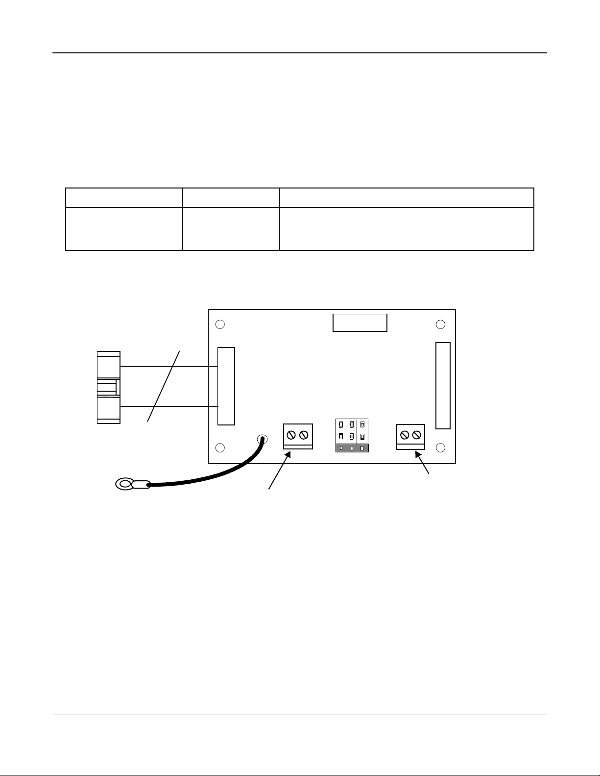
Description
NAME CODE NUMBER FUNCTIONS
Isolated Monitor Card
CM-B2/P
Connector to inverter control
board (2CN)
Grounding lead wire (connected
to terminal E (G) of inverter
control board
73600-DO12X Converts analog monitor signals (0 to 10V) to isolated signals
(0 to 10V, 4 to 20mA or 0 to 20mA).
CM-B2/P
12
TB1
E
Terminal block TB1 for
isolated signal output
TB2
HRD1
Analog monitor signals (0 to 10V) input
lead wire connected to terminals AM and
CM of inverter control board
CODE NO.
73600-DO120
Fig. 1 Isolated Monitor Card CM-B2/P
VS-616PC5/P5 Option Instruction Manual: Isolated Monitor Card CM-B2/P
Page 3
Page 4

INSTALLATION
1. Before attempting to install or use the Isolated Monitor Card CM-B2/P, read these instructions.
2. After unpacking the card, verify that you have received the correct code number and that no damage has occurred during shipping. Contact your YASKAWA representative if you should require
any assistance.
3. Turn OFF the main electrical power to the inverter.
4. Remove the inverter’s cover by first removing the digital operator. Then push inward (on the
cover) at the indented area located on each side of the cover, and lift the cover upward from the
rear of the cover. Refer to the VS-616PC5/P5 User’s Manual (YEA-TOA-S616-12), if necessary.
5. Check that the indicator CHARGE LED is OFF (indication that power is OFF).
6. Place the Isolated Monitor Card onto the four (4) stand-off posts in the control board aligning the
Isolated Monitor Card’s connector with the control board’s 2CN connector.
7. Gently push the Isolated Monitor Card downward onto the stand-off posts until they protrude
through the card’s holes, thereby engaging the card firmly to the posts.
8. Plug the Isolated Monitor Card’s connector into the Control Board’s 2CN connector.
9. Replace the inverter’s cover. Refer to Fig. 1 for correct wiring of the Isolated Monitor Card and
the Control Board.
Page 4
VS-616PC5/P5 Option Instruction Manual: Isolated Monitor Card CM-B2/P
Page 5
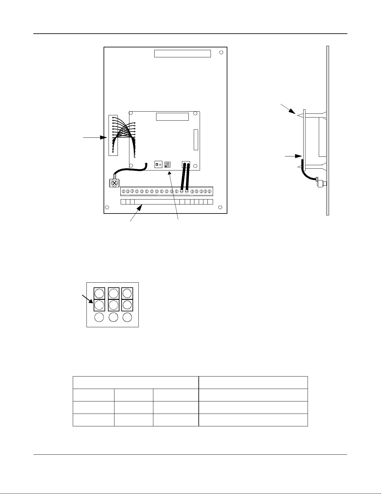
Stand Off Posts (4)
2CN option
connector
JUMPER
for
HDR1
2
1
1
S1S2
1
12
TP1
S3
CM-B2/P
TB1 TB2
1
HDR1
AM AC
CODE NO.
73600-D0120
GND
Connector
terminal
Refer to Fig. 3
FRONT VIEW
Fig. 2 Installation of Isolated Monitor Card CM-B2/P
3 6
3 6
2
2
1
1
5
5
4 7
4 7
9
9
8
8
Note: The three jumpers on the HRD1 are used to configure the
HDR 1
Configures Output Signal at TB1
output signal at TB1. Refer to Table 2 for additional data.
CM-B2/P
SIDE VIEW
HDR1
Fig. 3 Output Signal Configuration
HDR1 Jumper Positions
HDR1 JUMPER POSITIONS OUTPUT TB1
1-2 4-5 7-8 0 to 10 VDC
2-3 5-6 8-9 4 to 20 MA
1-2 4-5 8-9 0 to 20 MA
Note: Default 4 to 20mA
VS-616PC5/P5 Option Instruction Manual: Isolated Monitor Card CM-B2/P
Page 5
Page 6

INTERCONNECTION DIAGRAM
CAUTION
Fig. 4 shows the mounting and interconnection between the inverter and the Isolated Monitor Card
CM-B2/P.
L1 (R)
L2 (S)
L3 (T)
VS-616/PC5/P5
U (T1)
V (T2)
W (T3)
AC
AM
2CN
E (G)
2
TB2
1
12
2CN
E
TP1
Isolated Monitor Card
CM-B2/P
IM
TB1
P
Current
Output
250?
Fig. 4 Interconnection Diagram
!
WIRING NOTES
1. Separate the wires for output signals (from the Isolated Monitor Card’s terminal block TB1) from
the main circuit wires and other power cables.
2. Use a shielded wire to connect output signals. Connect the wire as shown in Fig. 5 to prevent
noise interference.
Shielded Sheath
C
B
A
Armor
Fig.5 Shielded Wire
Failure to observe these precautions may result in equipment malfunctions.
A. NEVER connect the wire’s shielded sheath when
connecting wires.
B. WRAP insulating tape around shielded areas and
wires where termination occurs.
C. CONNECT the shielded wire end to the Ground-
ing Terminal (E) on the inverter’s Terminal E (G).
Page 6
VS-616PC5/P5 Option Instruction Manual: Isolated Monitor Card CM-B2/P
Page 7

WIRING
Refer to the following table for the external function terminals:
External Function Terminals
TERMINAL BLOCK
SYMBOL
TB1
PIN
NUMBER
1 Isolated Monitor Output (+)
2 Isolated Monitor Output (-)
FUNCTIONS
Wiring Connection Notes:
1. To prevent noise, use shielded wire as specified in Fig. 5. Separate the power circuits
(200VAC or greater) and the relay drive circuits from the control wires.
2. Wire lengths must be 164ft (50m) or less.
3. Connect the grounding lead wire (E) to the inverter control board grounding terminal E (G).
4. Applicable wire sizes for terminal block TBI and TB2 are as listed in the following table:
Wire Sizes
TYPE [mm2] AWG I [A] VAC [V]
Thin twisted wire 1 16 12 125
Solid Wire 1.5 16 12 125
UL -- 22-16 10 300
CSA -- 28-16 10 300
CSA -- 28-16 10 150
Stripping TB1 and TB2 Wires for Connection
The following figure shows the correct length of insulation to be stripped in order to connect the
wire to terminal blocks TB1 and TB2.
5.5mm
Fig. 6 Terminal Block TB1 and TB2 Side for Connecting Wire End
Cable Selection:
1. Cable that is too heavy exerts pressure on the option card and may cause failure.
2. Cable too thin may cause a poor connection or may prematurely break.
VS-616PC5/P5 Option Instruction Manual: Isolated Monitor Card CM-B2/P
Page 7
Page 8

YASKAWA ELECTRIC AMERICA, INC.
Chicago-Corporate Headquarters 2942 MacArthur Blvd. Northbrook, IL 60062-2028, U.S.A.
Phone: (847) 291-2340 Fax: (847) 291-4203 Internet: http//www.yaskawa.com
Chicago-Technical Center 3160 MacArthur Blvd. Northbrook, IL 60062-1917, U.S.A.
Phone: (847) 291-0411 Fax: (847) 291-1018
MOTOMAN INC.
805 Liberty Lane West Carrollton, OH 45449, U.S.A.
Phone: (513) 847-6200 Fax: (513) 847-6277
YASKAWA ELETRICO DO BRASIL COMERCIO LTDA.
Avenida Brigadeiro Faria Lima, 1664-5° Andar, CJS 504/511 CEP 01452-001 - Sao Paulo-SP, Brasil
Phone: (011) 815-7723 Fax: (011) 210-9781
YASKAWA ELECTRIC EUROPE GmbH
Am Kronberger Hang 2, 65824 Schwalbach, Germany
Phone: (49) 6196-569-300 Fax: (49) 6196-888-301
Motoman Robotics AB
Box 130 S-38500. Torsas, Sweden
Phone: 0486-10575 Fax: 0486-11410
Motoman Robotec GmbH
Kammerfeldstra?e 1, 85391 Allershausen, Germany
Phone: 08166-900 Fax: 08166-9039
YASKAWA ELECTRIC UK LTD.
3 Drum Mains Park Orchardton Woods Cumbernauld, Scotland, G68 9LD, U.K.
Phone: (1236) 735000 Fax: (1236) 458182
YASKAWA ELECTRIC KOREA CORPORATION
Paik Nam Bldg. 901 188-3, 1-Ga Euljiro, Joong-Gu, Seoul, Korea
Phone: (02) 776-7844 Fax: (02) 753-2639
YASKAWA ELECTRIC (SINGAPORE) PTE. LTD.
Head Office: CPF Bldg. 79 Robinson Road #13-05, Singapore 0106, SINGAPORE
Phone: 221-7530 Telex: (87) 24890 YASKAWA RS Fax: 224-5854
Service Center: 221 Henderson Road, #07-20 Henderson Building Singapore 0315, SINGAPORE
Phone: 276-7407 Fax: 276-7406
YATEC ENGINEERING CORPORATION
Shen Hsiang Tang Sung Chiang Building 10F 146 Sung Chiang Road, Taipei, Taiwan
Phone: (02) 563-0010 Fax: (02) 567-4677
SHANGHAI OFFICE Room No. 8B Wan Zhong Building 1303 Yan An Road (West), Shanghai 200050, CHINA
Phone: (86) 212-1015 Fax: (86) 212-1015
TAIPEI OFFICE Shen Hsiang Tang Sung Chiang Building 10F 146 Sung Chiang Road, Taipei, Taiwan
Phone: (02) 563-0010 Fax: (02) 567-4677
TOKYO OFFICE 8th Floor, New Pier Takeshiba South Tower, 1-16-1, Kaigan, Minato-ku, Tokyo, 105, Japan
Phone: (03) 5402-4542 Fax: (03) 5402-4588 Internet: http//www.yaskawa.co.jp
Yaskawa Electric America, Inc., November, 1996 YEA-TOA-C736-40.23 Printed In U.S.A.
 Loading...