

Page 1
http://www.chinakong.com 中国工控网站收集整理
VS-616PC5/P5 Series
User’s Manual
Variable Torque Inverter
(with software version 5110/5120 and newer)
Page 2

!
WARNING
PRECAUTIONS
1) Read this manual in its entirety before installing or operating the VS616PC5/P5 inverter. This manual applies to inverters with software
versions 5110 and 5120 only and is not intended to be used in conjunction with any other software.
2) Do not connect or disconnect wiring, or perform signal checks while
the power supply is turned ON.
3) The VS-616PC5/P5 internal capacitor may be charged even after the
power supply is turned OFF. To prevent electric al shock, disconn ect all
power before servi cing the inverter . Then wait at least five minutes
after the power supply is disconnected and all LEDs are ext inguished.
4) Do not perf o rm a withstand volt a ge t e st or a megger test on any part
of the VS-616PC5/P5. This electronic equipment uses semiconductors and is vulnerable to high voltage.
5) Do not remove the operator unless the power supply is turned OFF .
Never touch the printed control board while the power supply is
turned ON.
6) The VS-616PC5/P5 is suitable for use on a circuit capable of delivering
not more than 65,000 RMS symmetrical amperes, 480 Volts maximum
(460V class units), 240 Volts maximum (230V cla ss units ).
Failure to observe these and other precautions highlighted in this manual
will expose the user to high voltages, resulting in equipment damage,
serious injury or death.
NOTICE
Printed April, 1999. The information contained within this document is
the proprietary property of Yaskawa Electric America, Inc., and may not
be copied, reproduced or transmitted to other parties without the
expressed written authorization of Yaskawa Electric America, Inc.
No patent liability is assumed with respect to the use of the information
contained herein. Moreover, because Yaskawa is constantly improving its
high-quality products, the information contained in this manual is subject
to change without notice. Every precaution has been taken in the preparation of this manual. Nevertheless, Yaskawa assumes no responsibility for
errors or omissions. Neither is any liability assumed for damages resulting from the use of the information contained in this publication.
2 VS-616PC5/P5 User’s Manual
Page 3

Contents
CONTENTS
Section Description Page
1 RECEIVING & INSTALLATION
1.1 I
1.2 S
VS-616PC5 . . . . . . . . . . . . . . . . . . . . . . . . . . . . . . . . . . . . 7
VS-616P5. . . . . . . . . . . . . . . . . . . . . . . . . . . . . . . . . . . . . . 9
1.3 P
Receiving . . . . . . . . . . . . . . . . . . . . . . . . . . . . . . . . . . . . . 1 1
Checking the Nameplate. . . . . . . . . . . . . . . . . . . . . . . . . 11
Identifying the Parts. . . . . . . . . . . . . . . . . . . . . . . . . . . . . 12
1.4 M
Precautions. . . . . . . . . . . . . . . . . . . . . . . . . . . . . . . . . . . . 13
Dimensions/Heat Loss. . . . . . . . . . . . . . . . . . . . . . . . . . . 15
Clearances . . . . . . . . . . . . . . . . . . . . . . . . . . . . . . . . . . . . 17
1.5 W
Precautions. . . . . . . . . . . . . . . . . . . . . . . . . . . . . . . . . . . . 18
Inspection. . . . . . . . . . . . . . . . . . . . . . . . . . . . . . . . . . . . . 18
Main Circuit Wiring . . . . . . . . . . . . . . . . . . . . . . . . . . . . 21
2 OPERATION
Precautions. . . . . . . . . . . . . . . . . . . . . . . . . . . . . . . . . . . . 30
2.1 T
2.2 D
2.3 LED D
2.4 O
3 PROGRAMMING F E ATURES
3.1 VS-616PC5/P5 P
3.2 P
3.3 VS-616PC5/P5 O
Accel/decel time adjustment. . . . . . . . . . . . . . . . . . . . . . 50
Automatic fault retry . . . . . . . . . . . . . . . . . . . . . . . . . . . . 51
Automatic restart after momentary power loss . . . . . . . 51
Carrier frequency. . . . . . . . . . . . . . . . . . . . . . . . . . . . . . . 51
NTRODUCTION
PECIFICATIONS
RELIMINARY INSPECTION
OUNTING
. . . . . . . . . . . . . . . . . . . . . . . . . . . . . . . . . . . 6
. . . . . . . . . . . . . . . . . . . . . . . . . . . . . . . . . . . 7
. . . . . . . . . . . . . . . . . . . . . . . . . 11
. . . . . . . . . . . . . . . . . . . . . . . . . . . . . . . . . . . . . . 13
Choosing a Location . . . . . . . . . . . . . . . . . . . . . . . . . . . . 13
Removing and Replacing the Digital Operator . . . . . . . 14
Removing and Replacing the Front Cover. . . . . . . . . . . 14
IRING
. . . . . . . . . . . . . . . . . . . . . . . . . . . . . . . . . . . . . . . . . 18
VS-616PC5 Connection Diagram . . . . . . . . . . . . . . . . . 19
VS-616P5 Connection Diagram. . . . . . . . . . . . . . . . . . . 20
T erminal Functions . . . . . . . . . . . . . . . . . . . . . . . . . . . . . 24
Wire and Terminal Screw Sizes . . . . . . . . . . . . . . . . . . . 25
Control Circuit Wiring. . . . . . . . . . . . . . . . . . . . . . . . . . . 28
RIAL OPERATION
. . . . . . . . . . . . . . . . . . . . . . . . . . . . . . . . 31
Display at Power-up . . . . . . . . . . . . . . . . . . . . . . . . . . . . 31
Operation Checkpoints . . . . . . . . . . . . . . . . . . . . . . . . . . 32
Basic Operation . . . . . . . . . . . . . . . . . . . . . . . . . . . . . . . . 32
IGITAL OPERATOR DISPLAY
ESCRIPTION
PERATION MODE SELECTION
. . . . . . . . . . . . . . . . . . . . . . . . . . . . . . . 36
. . . . . . . . . . . . . . . . . . . . . . . 35
. . . . . . . . . . . . . . . . . . . . . . 37
ARAMETERS
ARAMETER SET-UP
PERATION
& I
(n001~n1 16) . . . . . . . . . . . 41
NITIALIZ ATION
. . . . . . . . . . . . . . . 49
. . . . . . . . . . . . . . . . . . . . . . . . 50
VS-616PC5/P5 User’s M anual 3
Page 4

Contents
Current limit (Stall prevention). . . . . . . . . . . . . . . . . . . . 52
DC injection braking . . . . . . . . . . . . . . . . . . . . . . . . . . . . 54
Energy savings control . . . . . . . . . . . . . . . . . . . . . . . . . . 55
Frequency agree set point . . . . . . . . . . . . . . . . . . . . . . . . 57
Frequency meter or ammeter . . . . . . . . . . . . . . . . . . . . . 58
Frequency meter or ammeter calibration . . . . . . . . . . . . 58
Frequency signal adjustment. . . . . . . . . . . . . . . . . . . . . . 58
Jog operation . . . . . . . . . . . . . . . . . . . . . . . . . . . . . . . . . . 60
Jump frequencies. . . . . . . . . . . . . . . . . . . . . . . . . . . . . . . 60
MODBUS communication. . . . . . . . . . . . . . . . . . . . . . . 61
Motor overload detection . . . . . . . . . . . . . . . . . . . . . . . . 62
Multi-step speed selection. . . . . . . . . . . . . . . . . . . . . . . . 64
Phase loss detection. . . . . . . . . . . . . . . . . . . . . . . . . . . . . 65
PID Control . . . . . . . . . . . . . . . . . . . . . . . . . . . . . . . . . . . 66
Reverse run prohibit . . . . . . . . . . . . . . . . . . . . . . . . . . . . 68
Soft-start characteristics . . . . . . . . . . . . . . . . . . . . . . . . . 68
Speed limit adjustment . . . . . . . . . . . . . . . . . . . . . . . . . . 69
Stopping method . . . . . . . . . . . . . . . . . . . . . . . . . . . . . . . 70
T orque adjustment. . . . . . . . . . . . . . . . . . . . . . . . . . . . . . 72
T orque detection . . . . . . . . . . . . . . . . . . . . . . . . . . . . . . . 73
Tripless operation . . . . . . . . . . . . . . . . . . . . . . . . . . . . . . 74
V/f pattern adjustment. . . . . . . . . . . . . . . . . . . . . . . . . . . 75
Slip compensation . . . . . . . . . . . . . . . . . . . . . . . . . . . . . . 77
3.4 I
NPUTS
& O
UTPUTS
. . . . . . . . . . . . . . . . . . . . . . . . . . . . . . . 78
Multi-function input signals . . . . . . . . . . . . . . . . . . . . . . 78
Analog input signals . . . . . . . . . . . . . . . . . . . . . . . . . . . . 82
Multi-function output signals . . . . . . . . . . . . . . . . . . . . . 83
4DIAGNOSTICS
Precautions. . . . . . . . . . . . . . . . . . . . . . . . . . . . . . . . . . . . 86
4.1 M
AINTENANCE
NSPECTION
& I
. . . . . . . . . . . . . . . . . . . . . . 87
Periodic Inspection . . . . . . . . . . . . . . . . . . . . . . . . . . . . . 87
Parts Replacement Schedule. . . . . . . . . . . . . . . . . . . . . . 87
4.2 A
LARM
AULT DISPLAY
& F
. . . . . . . . . . . . . . . . . . . . . . . . . 88
Alarm Display . . . . . . . . . . . . . . . . . . . . . . . . . . . . . . . . . 88
Fault Display . . . . . . . . . . . . . . . . . . . . . . . . . . . . . . . . . . 89
Motor Faults. . . . . . . . . . . . . . . . . . . . . . . . . . . . . . . . . . . 92
A APPENDIX
A-1 B
A-2 D
A-3 CE C
RAKING CONNECTION DIAGRAMS
IGITAL OPERATOR MONITOR DISPLAY
ONFORMANCE
. . . . . . . . . . . . . . . . . . 94
. . . . . . . . . . . . . . 95
. . . . . . . . . . . . . . . . . . . . . . . . . . . . . . . 97
4 VS-616PC5/P5 User’s Manual
Page 5

Chapter 1 - Receiving & Installation
- CHAPTER 1 -
RECEIVING &
INSTALLATION
Section Description Page
1 RECEIVING & INSTALLATION
1.1 I
1.2 S
VS-616PC5 . . . . . . . . . . . . . . . . . . . . . . . . . . . . . . . . . . . . 7
VS-616P5. . . . . . . . . . . . . . . . . . . . . . . . . . . . . . . . . . . . . . 9
1.3 P
Receiving . . . . . . . . . . . . . . . . . . . . . . . . . . . . . . . . . . . . . 1 1
Checking the Nameplate. . . . . . . . . . . . . . . . . . . . . . . . . 11
Identifying the Parts. . . . . . . . . . . . . . . . . . . . . . . . . . . . . 12
1.4 M
Precautions. . . . . . . . . . . . . . . . . . . . . . . . . . . . . . . . . . . . 13
Dimensions/Heat Loss. . . . . . . . . . . . . . . . . . . . . . . . . . . 15
Clearances . . . . . . . . . . . . . . . . . . . . . . . . . . . . . . . . . . . . 17
1.5 W
Precautions. . . . . . . . . . . . . . . . . . . . . . . . . . . . . . . . . . . . 18
Inspection. . . . . . . . . . . . . . . . . . . . . . . . . . . . . . . . . . . . . 18
Main Circuit Wiring . . . . . . . . . . . . . . . . . . . . . . . . . . . . 21
NTRODUCTION
PECIFICATIONS
RELIMINARY INSPECTION
OUNTING
Choosing a Location . . . . . . . . . . . . . . . . . . . . . . . . . . . . 13
Removing and Replacing the Digital Operator . . . . . . . 14
Removing and Replacing the Front Cover. . . . . . . . . . . 14
IRING
. . . . . . . . . . . . . . . . . . . . . . . . . . . . . . . . . . . . . . . . . 18
VS-616PC5 Connection Diagram . . . . . . . . . . . . . . . . . 19
VS-616P5 Connection Diagram. . . . . . . . . . . . . . . . . . . 20
T erminal Functions . . . . . . . . . . . . . . . . . . . . . . . . . . . . . 24
Wire and Terminal Screw Sizes . . . . . . . . . . . . . . . . . . . 25
Control Circuit Wiring. . . . . . . . . . . . . . . . . . . . . . . . . . . 28
. . . . . . . . . . . . . . . . . . . . . . . . . . . . . . . . . . . 6
. . . . . . . . . . . . . . . . . . . . . . . . . . . . . . . . . . . 7
. . . . . . . . . . . . . . . . . . . . . . . . . 11
. . . . . . . . . . . . . . . . . . . . . . . . . . . . . . . . . . . . . . 13
VS-616PC5/P5 User’s M anual 5
Page 6

Chapter 1 - Receiving & Installation
Introduction
1.1 INTRODUCTION
The VS-616PC5/P5 is a series of
high quality,
variable torque inve rters.
With a power range of 5 to 500 HP, it provides all the functionality of
prior series, in a compact, low cost package. This functionality includes
Yaskawa proprietary features like full-range automatic torque boost, electronic thermal motor overload, energy savings and PID operation, lownoise operation and various other features. It also features a new digital
operator for simple programming. Utilizing the latest microprocessor
technology, members of Yaskawa’s design team have collaborated to
make the VS-616PC5/P5 the world’s first optimized inverter specifically
designed for variable torque applications.
This manual details installation, start-up and operating procedures for the
VS-616PC5/P5 series adjustable frequency drive controller . Descriptions
of diagnostic and troubleshooting procedures are also included herein.
6 VS-616PC5/P5 User’s Manual
Page 7
#
#
Chapter 1 - Receiving & Installation
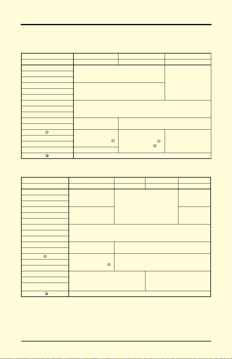
Specifications
1.2 SPECIFICATIONS
VS-616PC5
Inverter Model
Motor Output (HP) * 0.5 1 2 3 5 7.5 10 20 25 Capacity (kVA) 1.2 2.3 3.0 4.2 6.7 9.5 13 19 24 Rated Output
Current (A)-V T * *
Rated Output
Current (A)-CT**
Max. Voltage
Output Characteristics
Rated Output Fre quency 0.1 to 400 Hz
Overload Capacity - VT 120% Rate d Output Cu rrent for 1 minute
Overload Capacity - CT 150% Rated Out p ut Curren t f o r 1 minute
Input Cu rrent (A ) 3.9 7.2 9.6 13.2 21 33 44 65 82 Rated V oltage &
Frequency
Voltage Fluctuation +10%, -15%
Power Su pply
Frequency Fluctuation ±5%
Motor Output (HP) * 0.5 1 2 3 5 7.5 10 15 20 25
Capacity (kVA) 1.4 2.6 3.7 4.7 6.1 8.6 11 14 21 26
Rated Output
Current (A)-V T * *
Rated Output
Current (A)-CT**
Max. Voltage
Rated Output Fre quency 0.1 to 400 Hz
Output Character i st ics
Overload Capaci ty-VT**
Overload Capacity-CT** 150% Rated Outpu t Current f o r 1 minute
Inp u t C u r rent (A ) 2.3 4. 3 6.1 8.0 10.2 14.0 17.8 26.0 35.0 40.0
Rated V oltage &
Frequency
Voltage Fluctuation +10%, -15%
Power Supply
Frequency Fluctuation ±5%
VS-616PC5
CIMR-P5U
CIMR-P5U 40P4 40P7 41P5 42P2 43P7 44P0 45P5 47P5 4011 4015
20P4 20P7 21P5 22P2 23P7 25P5 27P5 2011 2015 -
3.2 6 8 11 17.5 27 36 54 68 -
3.2 6 8 11 17.5 25 33 49 64 3-Phase, 200/208/22 0/230V
(Proportional to input voltage)
3-Phase
220 - 230V, 50/60Hz
1.9 3.6 5.1 6.6 8.5 11.7 14.8 21.0 28.6 34.0
1.9 3.6 5.1 6.6 8.5 11.7 14.8 18 28.6 34.0
3-Phase, 380/400/415/440/460V
(Proportional to input voltage)
120% Rated Output Current for 1 minute
(Model 47P5 is rated 150% / 1 minute)
3-Phase
380 -440 - 460V, 50/60Hz
* HP ratings based on standard NEMA 4-pole motor data.
#
For 380V operation, the motor rated current must be less than or equal to the inverter
rated current.
** VT: Variable Torque rating (n116=1), CT: Constant Torque rating (n116=0)
Note: Shaded areas indicate factory settings.
VS-616PC5/P5 User’s M anual 7
Page 8

Chapter 1 - Receiving & Installation
Specifications
Control Method Sine wave PWM with full-range, automatic torque boost
Frequency Control
Range
Fre quency Ac curacy Digital command: 0.0 1%, Ana l og comm and: 0.1%
Frequency Setting Res olution
Output Frequency Resolution
Frequency Se tti ng 0 to +10VDC (20kΩ), 4-20mA (250Ω)
Control Charac teris tic s
Accel/De cel T im e
Braking Torq ue Approx. 20%
No. of V-f Patter ns 1 preset V/f pattern and 1 custom pattern
Motor Overl oad Protection
Instantaneous Ove rcurrent
Fus e Pro tection Motor coasts to stop at blown fuse.
Overload Motor coasts to stop after 1 min. at rated overload capacity.
Overvoltage
Undervoltage
Momentary P ower Loss
Protective Functions
Heatsink Overheat Thermi s tor - OH1, OH2
Stall Preven tion
Ground Fault Provided by electronic circuit
Power Charge Indication Charge LED stays on until v oltage drops below 50VDC
Inp u t P h a s e Lo s s Single-phase protection
Loc ation Indoor (protected from corrosive gases and dust)
Ambient
Temperature
Storage
Temperature
Humidity 95% RH (non-condens i ng)
Vibration
Environmental Conditions
Motor coasts to stop at approx. 200% rated output current.
Motor coasts to a stop if converter output voltage exceeds 410VDC
Motor coasts to stop if conv ert er output voltage drops below user
Immediat e s t op after 15 ms or longer power loss. (Continuous system ope ra-
tion dur ing power loss les s than 2 sec is eq uipped as standa r d.)
Stall prevention at acce leration/deceleration and const ant speed
+14 to 104°F (-10 to 40°C) for NEMA 1 type (not frozen)
9.8m/s2 (1G) less than 20Hz, up to 1.96m/s2 (0.2G) at 20 to 50Hz
Digital Operator Ref erence: 0.1Hz,
Analog Reference: 0.06Hz (@60Hz)
(Accel/Decel time setting independently: 0.1 sec )
Electronic thermal overload relay (I2T)
+14 to 113°F (-10 to 45°C) for open chassis type
0.1 to 400 Hz
0.01 Hz
0.0 to 3600.0 sec.
(820VDC at 460V input)
adjustable value
operation
-4 to 140°F (-20 to 60°C)
8 VS-616PC5/P5 User’s Manual
Page 9

Chapter 1 - Receiving & Installation
Specifications
VS-616P5
Motor Output (HP) * 30 40 50 60 75 100 125
Capacity (kVA) 303750617085110
Rated Output
Current (A) - VT **
Rated Output
Current (A) - CT **
Max. Voltage
Output Characteristics
Rated Output Frequenc y 0.1 to 400 Hz
Overload Capacity - VT ** 120% Rated Output Cur rent / 1 minute
Overload Capacity - CT ** 150% Rated Output Current / 1 minute
Input Cu r rent (A) 88 119 143 176 212 270 344
Rated Vo lta ge &
Frequen cy
Voltage Fluctuatio n +10%, -15%
Power Supply
Frequency Fluctuation ±5%
Motor Ou tput (HP) * 30 40 50 60 75 100 150 200 250 300 400 500
Cap a c i ty ( kVA) 31 40 50 61 73 98 130 170 230 260 340 460
Rated Output
Current (A) - VT **
Rated Output
Current (A) - CT **
Max. Voltage
Output Chara cter isti cs
Rated Output Frequenc y 0.1 to 400 Hz
Overload Capacity - VT * * 120% Rated Current / 1 minute
Overload Capacity - CT * * 150% Rated Current / 1 minute
Inp ut Current (A ) 46 58 72 88 106 141 198 264 330 456 608 810
Rated Vo lta ge &
Frequen cy
Voltage Fluctuatio n +10%, -15%
Power Supply
Frequency Fluctuation ±5%
Inverter M odel
CIMR-P5U
CIMR-P5U 4018 4022 4030 4037 4045 4055 4075 4110 4160 4185 4220 4300
#
#
2018 2022 2030 2037 2045 2055 2075
80 104 130 160 192 248 312
64 83 104 128 154 198 250
41 52 65 80 96 128 180 240 302 380 506 675
32 42 52 64 77 102 144 182 242 304 404 540
3-Phase, 380/400/415/440/460V
VS-616P 5
—
3-Phase, 200/208/220/230V
(Proportional to input voltage)
—
3-Phase
220 - 230V, 50/60Hz
(Proportional to input voltage)
3-Phase
380 -440 - 460V, 50/60Hz
* HP ratings based on standard NEMA 4-pole motor data.
#
For 380V operation, the motor rated current must be less than or equal to the inverter
rated current.
** VT: Variable Torque rating (n116=1), CT: Constant Torque rating (n116=0)
Note: Shaded areas indicate factory settings.
VS-616PC5/P5 User’s M anual 9
Page 10

Chapter 1 - Receiving & Installation
Specifications
Control Method Sine wave PWM with full-range, automatic torque boost
Frequency C o nt rol Range 0.1 to 400 Hz
Frequency Accuracy D igital comma nd: 0.01%, Analog command: 0.1%
Frequency Setting
Resolution
Output Frequency
Resolution
Frequen cy Setting 0 to +10VDC (20kΩ), 4-20mA (250Ω)
Control Characteristics
Accel/Decel Time
Braking Torque Approx. 20%
No. of V-f Patterns 1 preset V/f pattern and 1 custom pattern
Motor Ov erload Protection
Instantaneous Overcurrent Motor coasts to stop at approx. 180% rated output current.
Fuse Pro tection Motor coasts to stop at blown fuse.
Overload Motor coasts to stop after 1 min. at rated overload capacity.
Overvol tag e
Undervoltage
Momenta ry Power Loss
Protective Functions
Heatsink Overheat Thermistor - OH1, OH2
Stall Pre ve ntion Stall prevention at accele r ation/decelerat io n a nd constant speed operation
Ground Fault Provided by electronic circuit
Power Charge Indication Charge LED stays on until voltage drops below 50VDC
Input Ph as e L oss Single-phase protection
Location I ndoor (protected from corrosive gases an d dus t )
Ambient Temperature
Storage Temperature -4 to 140°F (-20 to 60°C)
Humidi ty 95% RH (non- co ndensing)
Vibrat ion
Environmental Conditions
Motor coasts to stop if converter output voltage exceeds 410VDC
Motor coas ts to st o p if co nv er ter output voltag e dr op s below user
Immediat ely stop after 1 5 m s or lo nger power loss . (C o nt i nuous system
operation during power loss less than 2 sec is equipped as standard.)
+14 to 104°F (-10 to 40°C) for NEMA 1 type (not frozen)
9.8m/s
Digital Operator Reference: 0.1Hz,
Analog Reference: 0.06Hz (@60Hz)
0.01 Hz
0.0 to 3600.0 sec.
(Accel/Decel time setting independently: 0.1 sec )
2
Electronic thermal overload relay (I
(820VDC at 460V input )
adjustable value
+14 to 113°F (-10 to 4 5°C ) for open cha ssis type
2
(1G) less than 20Hz, up to 1.96 m/s2 (0.2G) at 20 to 50Hz
T)
10 VS-616PC5/ P5 U s er’s Ma nual
Page 11
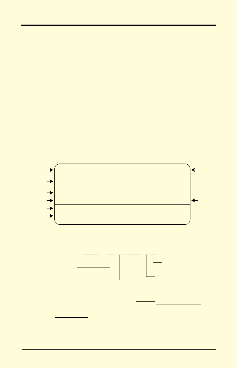
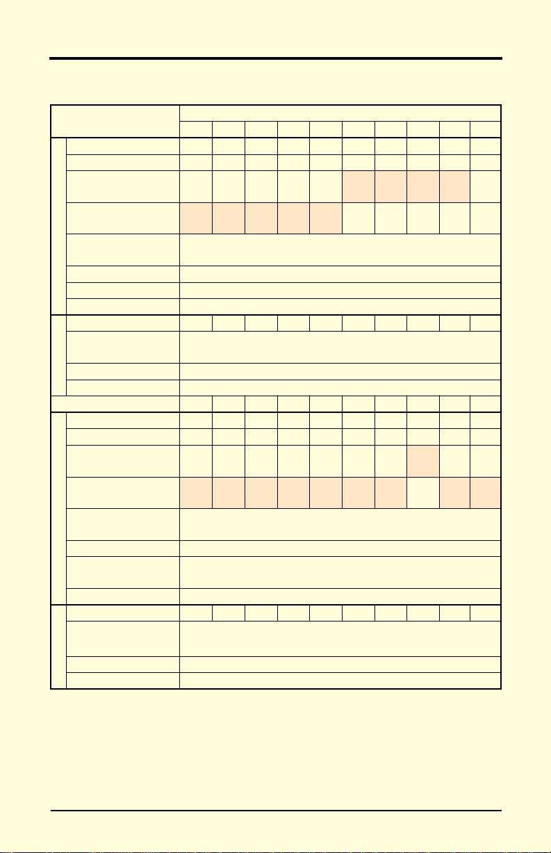
Figure 1 Nameplate Example of American Model CIMR-P5U43P7
Figure 2 Nameplate Description
Chapter 1 - Receiving & Installation
Preliminary Inspection
1.3 PRELIMINARY INSPECTION
Receiving
After unpacking the VS-616PC5/P5:
· Verify that the part numbers on the drive nameplate match the numbers on yo ur purchase order or packing sli p.
· Check the unit for physical damage which may have occurred durin g
shipping. If any part of the drive is missing or damaged, notify the
carrier and your Yaskawa representative immediately.
· Verify that all internal hardware (i.e. components, screws, etc.) is
seated properly and fastened securely.
· Verify that the instruction manual is included (YEA-TOA-S616-12).
· If the drive will be stored after receiving, place it in its original packaging and store according to temperature specifications on page 8.
Checking the Nameplate
Inverter
Model
Input Spec.
Output Spec.
Lot No.
Serial No.
UL File No.
MODEL :
INPUT :
OUTPUT :
LOT NO : MASS : 4.5 kg
SER NO :
UL FILE NO
:
CIMR - P5 U 4 3P7 1 F
Inverter
VS-616PC5/P5 Series
Specifications
A: Japanese specifications
E: European specifications
U: American specifications
Voltage Class
2: 3-phase, 230V
4: 3-phase, 460V
CIMR-P5U43P7
AC 3PH
AC 3PH 0-460V 6.1kVA 8.5A
E131457
380-440V 50Hz
380-460V 60Hz
SPEC :
10.2A
Enclosure
Model Designation
See Specifications, pp 7-10
43P71F_
Inverter
Spec.
Mass
Mg
Revision symbol
0: Open chassis
1: NEMA 1 (IP20)
3P7 to 300
VS-616PC5/P5 User’s M anual 11
Page 12
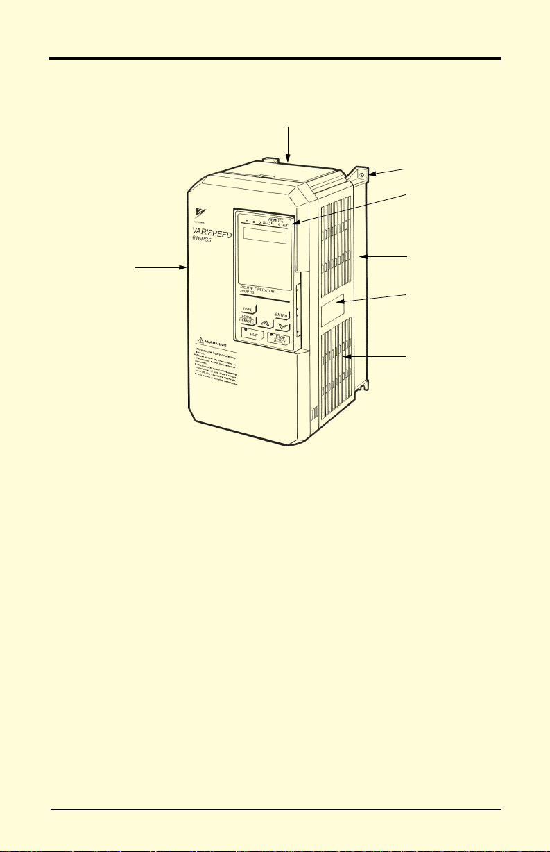
Figure 3 Parts Identification - Model CIMR-P5U43P7
Chapter 1 - Receiving & Installation
Preliminary Inspection
Identifying the Parts
Front Cover
Protective Cover (top/bottom)
4 Mounting Holes
Digital Operator
D
R
I
V
E
F
W
D
R
E
V
0
P
JVOP-130P
Heatsink
Nameplate
Ventilation Slots
12 VS-616PC5/ P5 U s er’s Ma nual
Page 13

Chapter 1 - Receiving & Installation
Mounting
1.4 MOUNTING
!
CAUTION
PRECAUTIONS
1) When preparing to mount the VS-616PC5/P5, lift it by its base. Never
lift it by the front cover.
2) Mount the inverter onto nonflammable material.
3) The VS-616PC5/P5 generates heat. For the most effective cooling
possible, mount it vertically. For more details, refer to “Dimensions/
Heat Loss” on pages 15 & 16 and “Clearances” on page 17.
4) When mounting units in an enclosure, install a fan or other cooling
device to keep the intake air temperature below 113°F (45°C).
Failure to observe these precautions may result in equipment damage.
Choosing a Location
Be sure that the inverter is mounted in a location protected against the following conditions:
· Extreme cold and heat. Use only within the ambient temperature range:
14 to 104°F (-10 to 40°C).
· Direct sunlight (not for use outd oo rs )
· Rain, moisture
· High humidity
· Oil sprays, splash es
· Salt spray
· Dust or metallic particles in the air
· Corro sive gases (e.g. sulfurized gas) or liqu i ds
· Radioactive substances
· Combustibles (e.g. thinner, solvents, etc.)
· Physical shock, vibration
· Magnetic noise (e.g. welding machines, power devices, etc.)
VS-616PC5/P5 User’s M anual 13
Page 14
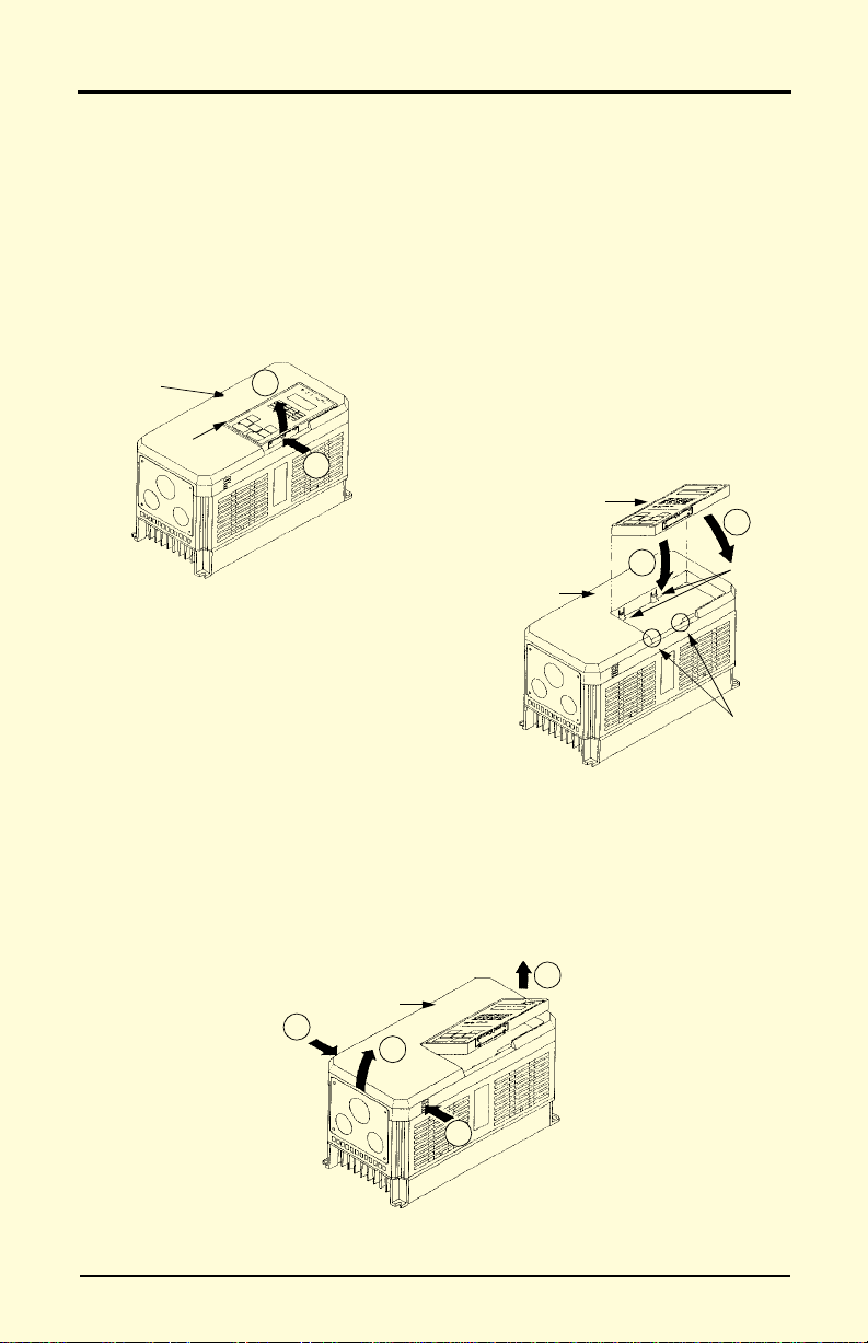
Figure 4 Removing the Digital Operator
Figure 5 Replacing the Digital Operator
Figure 6 Removing and Replacing the Front Cover
Chapter 1 - Receiving & Installation
Mounting
Removing and Replacing the Digital Operator
To remove the digital operator from the front cover, push the operator
lever in the direction shown by arrow 1 and lift the digital operator in the
direction shown by arrow 2 (see Figure 4).
To replace the digital operator, engage the operator onto retaining tabs A
in the direction shown by arrow 1 and then onto retaining tabs B in the
direction shown by arrow 2, locking the digital operator into place (see
Figure 5).
Front Cover
Digital Operator
2
1
Digital Operator
2
1
Front Cover
Retaining
Ta bs A
Retaining
Tabs B
Removing and Replacing the Front Cover
To remove the front cover, first remove the digital operator (see previous
section). Then squeeze the cover on both sides in the direction shown by
arrows 2 and lift the cover in the direction shown by arrow 3.
1
Front Cover
2
3
14 VS-616PC5/ P5 U s er’s Ma nual
2
Page 15

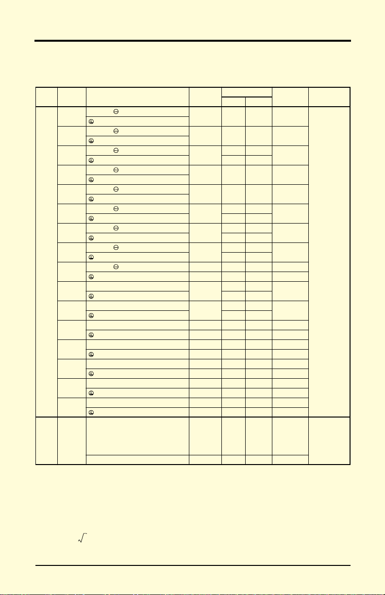
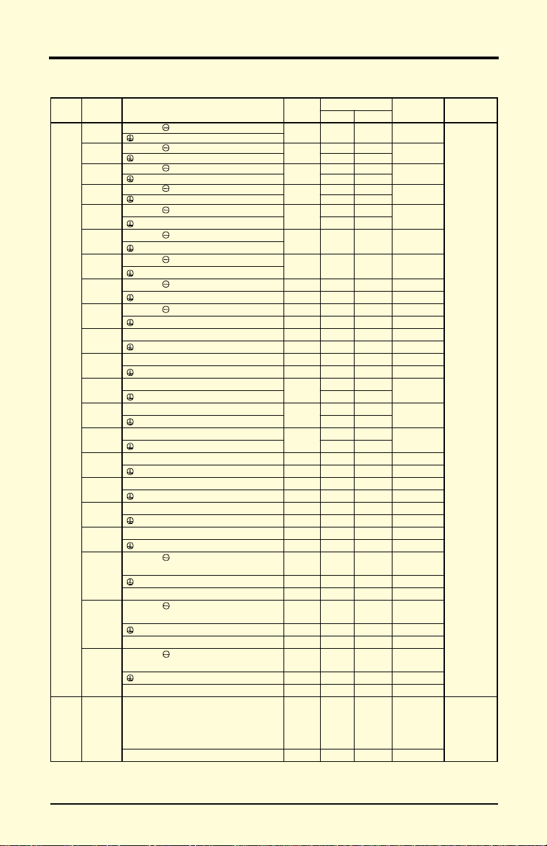
Dimensions/Heat Loss
Chapter 1 - Receiving & Installation
Mounting
Open Chassis Type (IP00)
Model
Voltage
CIMR
230V
460V
WHDW1H1H2
-P5U
20P4
5.51 (140) 11.02 (280) 6.30 (160) 4.96 (126) 10.47 (266) 0.28 (7) 6.5 (3)
20P7 25 65 90
21P5 40 80 120
22P2
5.51 (140) 11.02 (280) 7.09 (180) 4.96 (126) 10.47 (266) 0.28 (7) 10 (4.5)
23P7 135 80 215
25P5
7.87 (200) 11.81 (300) 8.07 (205) 7.32 (186) 11.22 (285) 0.31 (8)
27P5
2011
9.84 (250) 14.96 (380) 8.86 (225) 9.29 (236) 14.37 (365) 0.30 (7.5) 24 (11)
2015
2018
12.80 (325) 17.72 (450) 11 .2 2 (285) 10.83 (275) 17.13 (435) 0.30 (7.5) 62 (28)
2022
2030
16.73 (425) 26.57 (675) 13.78 (350) 12.60 (320) 25.59 (650) 0.49 (12.5)
2037
2045
18.70 (475) 31.50 (800) 13.78 (350) 14.57 (370) 30.51 (775) 0.49 (12.5) 176 (80)
2055
2075 22. 64 (5 75) 36.42 (925) 15.75 (400) 17.52 (445) 35.24 (895) 0.59 (15) 298 (135) 2300 1300 3600
40P4
40P7
5.51 (140) 11.02 (280) 6.30 (160) 4.96 (126) 10.47 (266) 0.28 (7)
41P5
42P2
43P7
5.51 (140) 11.02 (280) 7.09 (180) 4.96 (126) 10.47 (266) 0.28 (7) 10 (4.5)
44P0
45P5
7.87 (200) 11.81 (300) 8.07 (205) 7.32 (186) 11.22 (285) 0.31 (8) 13 (6)
47P5
4011
9.84 (250) 14.96 (380) 8.86 (225) 9.29 (236) 14.37 (365) 0.30 (7.5) 24 (11)
4015
4018
12.80 (325) 17.72 (450) 11 .2 2 (285) 10.83 (275) 17.13 (435) 0.30 (7.5) 60 (27)
4022
4030
4037
12.80 (325) 24.61 (625) 11 .2 2 (285) 10.83 (275) 24.02 (610) 0.30 (7.5) 97 (44)
4045
4055
17.91 (455) 32.28 (820) 13.78 (350) 13.78 (350) 31.30 (795) 0.49 (12.5)
4075
4110
22.64 (575) 36.42 (925)
4160 15.75 (400) 320 (145) 2670 1520 4190
4185
37.40 (950) 57.09 (1450) 17.13 (435) 29.53 (750) 55.12 (1400) 0.98 (25) 794 (360)
4220
37.80 (960) 62.99 (1600) 17.91 (455) 29.53 (750) 61.02 (1550) 0.98 (25) 926 (420) 6820 2910 9730
4300
Open Chassis Dimensions in inches (mm)
14.76 (375)
17.52 (445) 35.24 (895) 0.59 (15)
Mass
lbs (kg)
12 (5.5) 210 90 300
13 (6) 235 110 345
134 (61) 1050 500 1550
137 (62) 1250 700 1950
6.5 (3)
8.8 (4) 30 80 110
174 (79) 1110 710 1820
176 (80) 1430 890 2320
298 (135) 1870 1160 3030
Heat Loss (W)
Heat
Inside
unit
Total
sink
15 50 65
80 60 140
425 160 585
525 200 725
655 230 885
830 280 1110
1550 750 2300
1950 1000 2950
10 50 60
20 65 85
65 60 125
80 65 145
120 80 200
135 85 220
240 120 360
305 150 455
390 180 570
465 195 660
620 260 880
705 315 1020
875 370 1245
970 415 1385
3400 1510 4910
4740 2110 6850
VS-616PC5/P5 User’s M anual 15
Page 16

Chapter 1 - Receiving & Installation
Mounting
Enclosed Type (NEMA 1, IP20)
Model
Voltage
(CIMR-
P5U)
20P4
5.51 (140) 11.02 (280) 6.30 (160) 4.96 (126) 10.47 (266) 0.28 (7) 6.5 (3)20P7
21P5
22P2
5.51 (140) 11.02 (280) 7.09 (180) 4.96 (126) 10.47 (266) 0.28 (7) 10 (4.5)
23P7
25P5
7.87 (200) 11.81 (300) 8.07 (205) 7.32 (186) 11.22 (285) 0.31 (8)
27P5
2011
230V
460V
9.84 (250)
2015
2018
12.99 (330)
2022
2030
16.93 (430) 38.78 (985) 13.78 (350) 12.60 (320) 25.59 (650) 8.37 (212.5)
2037
2045
18.90 (480) 43.70 (1110) 13.78 (350) 14.57 (370) 30.51 (775) 8.37 (212.5) 192 (87)
2055
2075 22.83 (580) 50.79 (1290) 15.75 (400) 17.52 (445) 35.24 (895) 10.63 (270) 320 (145)
40P4
5.51 (140) 11.02 (280) 6.30 (160) 4.96 (126) 10.47 (266) 0.28 (7)
40P7
41P5 8.8 (4)
42P2
5.51 (140) 11.02 (280) 7.09 (180) 4.96 (126) 10.47 (266) 0.28 (7) 10 (4.5)43P7
44P0
45P5
7.87 (200) 11.81 (300) 8.07 (205) 7.32 (186) 11.22 (285) 0.31 (8) 13 (6)
47P5
4011
9.84 (250) 14.96 (380) 8.86 (225) 9.29 (236) 14.37 (365) 0.30 (7.5) 24 (11)
4015
4018
12.99 (330) 24.02 (610) 11.22 (285) 10.83 (275) 17.13 (435) 3.44 (87.5) 68 (31)
4022
4030
4037
12.99 (330)
4045
4055
18.11 (460) 44.49 (1130) 13.78 (350) 13.78 (350) 31.30 (795) 8.37 (212.5)
4075
4110
22.83 (580) 50.79 (1290)
4160 15.75 (400) 342 (155)
14.96 (380)
15.75 (400) 1.08 (27.5)
24.02 (610)
26.57 (675) 6.00 (152.5)
30.91 (785)
33.46 (850) 6.00 (152.5)
NEMA 1 Dimensions in inches (mm)
8.86 (225) 9.29 (236) 14.37 (365)
11.22 (285) 10.83 (275) 17.13 (435)
11.22 (285) 10.83 (275) 24.02 (610)
14.76 (375)
17.52 (445) 35.24 (895) 10.63 (270)
0.30 (7.5)
3.44 (87.5)
3.44 (87.5)
Mass
lbs (kg)WHDW1H1H2
12 (5.5)
13 (6)
24 (11)
71 (32)
148 (67)
150 (68)
6.5 (3)
106 (48)
187 (85)
190 (86)
320 (145)
16 VS-616PC5/ P5 U s er’s Ma nual
Page 17
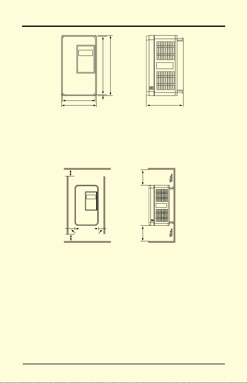
Front View
Side View
Figure 7 VS-616PC5/P5 Dimension Diagram
Front View
Side View
Figure 8 VS-616PC5/P5 Clearances
Chapter 1 - Receiving & Installation
Mounting
H
H1
W1
W
H2
D
Clearances
When mounting the VS-616PC5/P5, allow sufficient clearances for effective cooling as shown below:
1.97in (50mm)
1.18in (30mm)
1.97in (50mm)
4.72in (120mm)
4.72in (120mm)
Air
Air
Notes:
1) The required clearances at the top, bottom, and both sides of the inverter are the same
for both open chassis and NEMA 1 enclosures.
2) For inverter models 25HP and less (230V & 460V), remove the top and bottom covers
to convert NEMA 1 units to open chassis
3) Allowable intake air temperature:
Open chassis: 14°F to 113°F (-10°C to +45°C)
NEMA 1: 14°F to 104°F (-10°C to 40°C)
4) Whe n mounting units in an enclosure, install a fan or other cooling device to limit the
air temperature within the inverter to below 113°F (45°C).
VS-616PC5/P5 User’s M anual 17
Page 18

Chapter 1 - Receiving & Installation
Wiring
1.5 WIRING
!
CAUTION
PRECAUTIONS
1) Do not connect or disconnect wiring, or perform signal checks while
the power supply is turned ON.
2) Connect the power supply wiring to terminals L1, L2 and L3 on the
main circuit input section. DO NOT connect the power supply wiring
to output terminals T1, T2 and T3.
3) Connect the motor wiring to terminals T1, T2 and T3 on the main circuit output section.
4) Never touch the output circuit directly or place the output line in contact with the inverter enclosure.
5) Do not connect a phase-advancing capacitor or an LC/RC noise filter
to the output circuit.
6) The motor wiring must be less than 328ft (100m) in length and in a
separate conduit from the input power wiring.
7) Control wiring must be less than 164ft (50m) in length and in a separate conduit from both the motor wiring and the power wiring.
8) T ighten the screws on the main circuit and control circuit terminals.
9) Low voltage wires shall be wired with Class 1 wiring.
10)Please observe national electrical code (NEC) when wiring electrical
devices.
Failure to observe these precautions may result in equipment damage.
Inspection
After wiring is complete, verify that:
All wiring is correctly installed.
Excess screws and wire clippings are removed from inside of the unit.
Screws are securely tightened.
Exposed wire has no contact with other wiring or terminals.
18 VS-616PC5/ P5 U s er’s Ma nual
Page 19
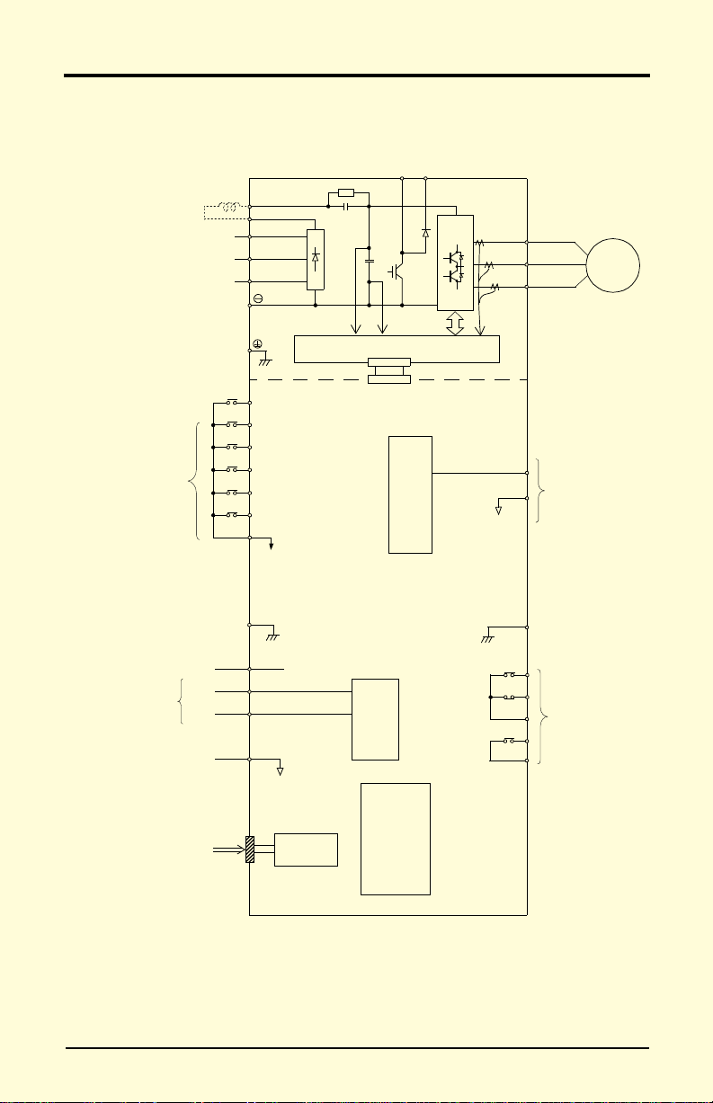
Figure 9 VS-616PC5 Terminal Diagram
230V: Models 20P4 through 27P5
460V: Models 40P4 through 4015
Chapter 1 - Receiving & Installation
Wiring
VS-616PC5 Standard Connection Diagram
DC Link Reactor (option)
Ground
230V units: 100Ω or less
460V units: 10Ω or less
Multi-Function
Contact Inputs
1
⊕
2
⊕
L1
L2
L3
S1 - Fixed
S2
S3
S4
S5
S6
SC (Com)
G
Gate Drive
PWM
8 bit
B1 B2
0~10V
(Com) AC
G
AM
T1
T2
T3
IM
Multi-Function
Analog Outputs
FS
Analog Inputs
Input FI selectable
4~20mA
or
0~10V
Serial Port
0~+10V
4~20mA
(+15V)
FV
(20kΩ)
FI
(250Ω)
(0V)
FC
RS-232
(10-pin)
A/D
10 bit
Operator
Digital
MA
MB
MC
M1
M2
VS-616PC5/P5 User’s M anual 19
Multi -Function
Contact Outputs
250VAC, 1A or less
30VDC, 1A or less
Page 20
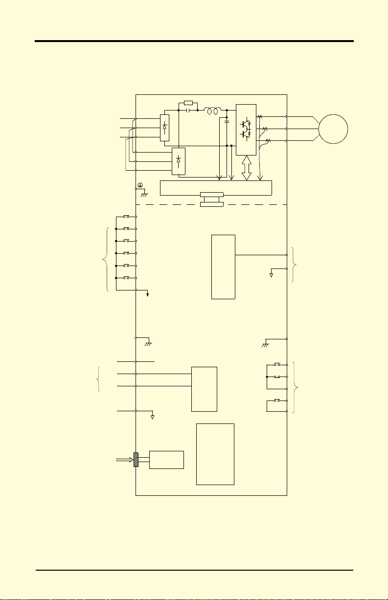
Figure 10 VS-616P5 Terminal Diagram
230V: Models 2018 through 2075
460V: Models 4018 through 4160
Chapter 1 - Receiving & Installation
Wiring
VS-616P5 Standard Connection Diagram
L1
L2
L3
L11
L21
L31
Ground
230V units: 100Ω or less
460V units: 10Ω or less
Multi-Function
Inputs
S1 - Fixed
S2
S3
S4
S5
S6
SC (Com)
G
Gate Drive
PWM
8 bit
0~10V
(Com) AC
G
AM
T1
T2
T3
IM
Multi-Function
Analog Outputs
FS
Analog Inputs
Input FI selectable
4~20mA
or
0~10V
Serial Port
0~+10V
4~20mA
(+15V)
FV
(20kΩ)
FI
(250Ω)
(0V)
FC
RS-232
(10-pin)
A/D
10 bit
Operator
Digital
MA
MB
MC
M1
M2
20 VS-616PC5/ P5 U s er’s Ma nual
Multi -Function
Relay Outputs
250VAC, 1A or less
30VDC, 1A or les s
Page 21

Chapter 1 - Receiving & Installation
Wiring
Main Circuit Wiring
Input Wiring
· Molde d-Case Circuit Breaker ( MCCB)
Be sure to connect MCCBs or fuses between the AC main circuit power
supply and VS-616PC5/P5 input terminals L1, L2 and L3, to protect the
power supp l y wi ri ng .
· Ground Fault Interrupter
When connecting a ground fault interrupter to input terminals L1, L2
and L3, select one that is not affected by high frequency.
Examples: NV series by Mitsubishi Electric Co., Ltd. (manufactured
in or after 1988), EGSG series by Fuji Electric Co., Ltd.
(manufactured in or after 1984).
· Magnetic Contactor (MC)
Inverters can be used without an MC installed on the power supply side.
An MC can be used instead of an MCCB to apply the main circuit
power supply. However, when an MC is switched OFF on the primary
side, dynamic braking does not function and the motor coasts to stop.
The load can be operated/stopped by closing/opening the MC on the
primary side. However, frequent switching may cause the inverter to
malfunction.
When using a braking resistor unit, use an MC to break the power supply
side of the inverter in the event of a dynamic braking overload relay trip.
Otherwise, if the inverter malfunctions, the braking resistor unit may be
burned out.
· Terminal Block Connect i on Sequence
Input power supply phases can be connected to any terminal regardless
of the order of L1, L2 and L3 on the terminal block.
· AC Reactor
When conn ecti n g an i nver te r (2 30 V/4 60 V, 25HP or les s) to a large capacity power supply transformer (600kVA or more), or when switching a
phase-advancing capacitor, excessive peak current flows through the input
power supply circuit, which may damage the converter section. In such
cases, install a DC reactor (optional) between inverter ⊕1 and ⊕2 terminals, or an AC reactor (optional) on the input side. Installation of a reactor
is also effective for improving power factor on the power supply side.
VS-616PC5/P5 User’s M anual 21
Page 22

n054
Chapter 1 - Receiving & Installation
Wiring
· Surge Suppressor
For inductive loads (i.e. magnetic contactors, magnetic relays, magnetic
valves, solenoids, magnetic brakes, etc.) connected near the inverter,
use a surge suppressor across the coils to limit the transients on the supply lines.
Output Wiring
· Motor Connec ti on
Connect motor lead wires to output terminals T1, T2 and T3. Verify that
the motor rotates in the forward direction (CCW: counterclockwise
when viewed from the motor load side) with the forward run command.
If the motor rotation is incorrect, exchange any two of the motor leads.
· Magnetic Starter
Do not connect a magnetic starter or a magne tic contactor to the output
circuit. If the motor load is connected or di sconnected while the inverter
is running, the inverter overcurrent protective circuitry may trip.
· Thermal Overload Relay
An electronic overload protective function (I
2
t) is incorporated into the
inverter. However, when driving several motors with one inverter, or
when switching between multiple windings of a multiple winding
motor, use an external thermal overload relay(s). In this case, set parameter n034 to “Disabled”.
· Wiring Distance Between Inverter and Motor
If the total wiring distance between inverter and motor is excessively
long and the inverter carrier frequency (IGBT switching frequency) is
high, harmonic leakage current from the wiring will adversely affect the
inverter and peripheral devices. If the wiring distance is long, reduce
the inverter carrier frequency as described below. C arrier frequency can
be set by param et er n054.
Wiring Distance Between Inverter and Motor
Wiring Distance between
Inverter and Motor
Carrier Frequency *
(Set value of parameter
)
Up to 164 ft.
(50m)
15kHz or less
(6)
Up to 328 ft.
(100m)
10kHz or l ess
More than 328 ft.
(4)
* Increasing the carrier frequency above the factory default value requires
current derating. Contact your Yaskawa representative for details.
22 VS-616PC5/ P5 U s er’s Ma nual
(100m)
5kHz or less
(2)
Page 23

Chapter 1 - Receiving & Installation
Figure 11 Grounding Example of 3 VS-616P5 Inverters
(a) Acceptable
(b) Acceptable
(c) Not Acceptable
Wiring
Grounding
· Ground Resistance
230V clas s: 10 0Ω or less, 460V class: 10Ω or less.
· Never ground the VS-616PC5/P5 in common with welding machines,
motors, or other high-current electrical equipment. Run all ground wiring in a separate conduit.
· Use ground wiring as specified in “Wire and Terminal Screw Sizes” on
page 25, and keep the length as short as possible.
· Whe n using severa l VS-616PC5/P5 units side by side, groun d the units
as shown in Figure 10, (a) or (b). Do not loop the wires as shown in (c).
VS-616PC5/P5 User’s M anual 23
Page 24
Chapter 1 - Receiving & Installation
Wiring
Terminal Functions
230V Class Terminal Functions
Model CIMR-P5U 20P4 to 27P5 2011 to 2015 2018 to 2075
Nominal Motor Output 0.5 to 10HP 20 to 25HP 30 to 125HP
L1
L2
L3
L11
L31
T1
T3
B1
B2
1
⊕
2
⊕
3 ---
⊕
DC power supply (⊕1 -
460V Class Terminal Functions
Model CIMR-P5U 40P4 to 4015 4018 to 4045 4055 to 4160 4185 to 4300
Nominal Motor Output 0.5 to 25HP 30 to 75HP 100 to 250HP 300 to 500HP
L1
L2
L3
L11
L31
T1
T3
s
s
B1
B2
⊕
⊕
200
400
1
2
r
Brakin g resistor unit ---
DC reactor (⊕1 - ⊕2)
DC power supply (⊕1 -
Main circuit input power supply
---L21
Inverter outputT2
Braking resistor unit ---
DC reactor (⊕1 - ⊕2)
Ground terminal (Ground resistance: 100Ω or less)
DC reactor (⊕1 - ⊕2)
)
DC power supply (⊕1 -
Braking unit (⊕3 -
)
Main circuit input
power supply
Main circuit input power supply
--- ---L21
Inverter outputT2
)
---
Ground terminal (Ground resistance: 10Ω or less)
r - s 200: 200 to 230 VAC input
r - s 400: 380 to 460 VAC input
Main circuit input
power supply
)
Main circuit input
power supply
---
Cooling fan power supply
(Control power supply)
---
24 VS-616PC5/ P5 U s er’s Ma nual
Page 25
Wire and Terminal Screw Sizes
-3
Chapter 1 - Receiving & Installation
Wiring
230V Class Wire Size
Model
Circuit
CIMR-
L1, L2, L3, , ⊕1, ⊕2, B1, B2, T1, T2, T3
P5U20P4
L1, L2, L3, , ⊕1, ⊕2, B1, B2, T1, T2, T3
P5U20P7
L1, L2, L3, , ⊕1, ⊕2, B1, B2, T1, T2, T3
P5U21P5
L1, L2, L3, , ⊕1, ⊕2, B1, B2, T1, T2, T3
P5U22P2
L1, L2, L3, , ⊕1, ⊕2, B1, B2, T1, T2, T3
P5U23P7
L1, L2, L3, , ⊕1, ⊕2, B1, B2, T1, T2, T3
P5U25P5
L1, L2, L3, , ⊕1, ⊕2, B1, B2, T1, T2, T3
P5U27P5
L1, L2, L3, , ⊕1, ⊕2, ⊕3, T1, T2, T3
P5U2011
Main
Control
* Wire sizes are based on 75°C copper wire.
L1, L2, L3, , ⊕1, ⊕2, ⊕3, T1, T2, T3 M8 3 30 90.3 (10.2)
P5U2015
L1, L2, L3, L11, L21, L31, T1, T2, T3
P5U2018
L1, L2, L3, L11, L21, L31, T1, T2, T3
P5U2022
L1, L2, L3, L11, L21, L31, T1, T2, T3 M10 4/0 100 203.6 (23.0)
P5U2030
L1, L2, L3, L11, L21, L31, T1, T2, T3 M10 1/0 x 2P 60 x 2P 203.6 (23.0)
P5U2037
L1, L2, L3, L11, L21, L31, T1, T2, T3 M10 1/0 x 2P 60 x 2P 203.6 (23.0)
P5U2045
L1, L2, L3, L11, L21, L31, T1, T2, T3 M10 1/0 x 2P 60 x 2P 203.6 (23.0)
P5U2055
L1, L2, L3, L11, L21, L31, T1, T2, T3 M12 4/0 x 2P 100 x 2P 349.6 (39.5)
P5U2075
S1, S2, S3, S4, S5, S6, SC
Common
FV, FI, FS, FC
to all
AM, AC, M1, M2, MA, MB, MC
models
G M3.5 20 - 14 0.5 - 2 8.9 (1.0)
Terminal Symbol
Terminal
Screw
M4 14 - 10 2 - 5.5 12.4 (1.4)
M4 14 - 10 2 - 5.5 12.4 (1.4)
M4
M4 12 - 10 3.5 - 5.5 12.4 (1.4)
M4 10 5.5 12.4 (1.4)
M5
M5
M6
M6 8 8 45.1 (5.1)
M8
M8
M8 4 22 90.3 (10.2)
M8 4 22 90.3 (10.2)
M8 4 22 90.3 (10.2)
M8 3 30 90.3 (10.2)
M8 1 50 90.3 (10.2)
Wire Size *
AWG mm
14 - 10 2 - 5.5
12 - 10 3.5 - 5.5
88
10 - 8 5.5 - 8
88
10 - 8 5.5 - 8
422
88
330
614
238
614
- 20 - 16
Stranded
0.5 - 1.25
Solid
0.5 - 1.25
2
Max. Torque
lb-in (N·m)
12.4 (1.4)
22.1 (2.5)
22.1 (2.5)
45.1 (5.1)
90.3 (10.2)
90.3 (10.2)
-
Wire Type
Power cable:
600V vinyl
sheathed wire
or equivalent
Twisted
shielded wire
with Class 1
wiring
Note:
Voltage drop should be considered when determining wire size. Voltage drop can be
calculated using the following equation:
Phase-to phase voltage dr op (V )
wire resistance (Ω/km) x wiring distance (m) x current (A) x 10
3=
Select a wire size so that voltage drop will be less than 2% of the normal rated voltage.
VS-616PC5/P5 User’s M anual 25
Page 26
Chapter 1 - Receiving & Installation
Wiring
460V Class Wire Size
Model
Circuit
CIMR-
L1, L2, L3, , ⊕1, ⊕2, B1, B2, T1, T2, T3
P5U40P4
L1, L2, L3, , ⊕1, ⊕2, B1, B2, T1, T2, T3
P5U40P7
L1, L2, L3, , ⊕1, ⊕2, B1, B2, T1, T2, T3
P5U41P5
L1, L2, L3, , ⊕1, ⊕2, B1, B2, T1, T2, T3
P5U42P2
L1, L2, L3, , ⊕1, ⊕2, B1, B2, T1, T2, T3
P5U43P7
L1, L2, L3, , ⊕1, ⊕2, B1, B2, T1, T2, T3
P5U45P5
L1, L2, L3, , ⊕1, ⊕2, B1, B2, T1, T2, T3
P5U47P5
L1, L2, L3, , ⊕1, ⊕2, B1, B2, T1, T2, T3 M5 8 - 6 8 - 14 22.1 (2.5)
P5U4011
L1, L2, L3, , ⊕1, ⊕2, B1, B2, T1, T2, T3 M5 8 - 6 8 - 14 22.1 (2.5)
P5U4015
L1, L2, L3, L11, L21, L31, T1, T2, T3 M6 6 14 45.1 (5.1)
P5U4018
L1, L2, L3, L11, L21, L31, T1, T2, T3 M6 4 22 45.1 (5.1)
P5U4022
L1, L2, L3, L11, L21, L31, T1, T2, T3
P5U4030
Main
Control
* Wire sizes are based on 75°C copper wire.
L1, L2, L3, L11, L21, L31, T1, T2, T3
P5U4037
L1, L2, L3, L11, L21, L31, T1, T2, T3
P5U4045
L1, L2, L3, L11, L21, L31, T1, T2, T3 M10 4/0 100 203.6 (23.0)
P5U4055
L1, L2, L3, L11, L21, L31, T1, T2, T3 M10 1/0 x 2P 60 x 2P 203.6 (23.0)
P5U4075
L1, L2, L3, L11, L21, L31, T1, T2, T3 M10 1/0 x 2P 60 x 2P 203.6 (23.0)
P5U4110
L1, L2, L3, L11, L21, L31, T1, T2, T3 M12 4/0 x 2P 100 x 2P 349.6 (39.5)
P5U4160
L1, L2, L3, , ⊕1, ⊕3, T1, T2, T3
P5U4185
r, s200, s400 M4 20 - 10 0.5 - 5.5 12.4 (1.4)
L1, L2, L3, , ⊕1, ⊕3, T1, T2, T3
P5U4220
r, s200, s400 M4 20 - 10 0.5 - 5.5 12.4 (1.4)
L1, L2, L3, , ⊕1, ⊕3, T1, T2, T3
P5U4300
r, s200, s400 M4 20 - 10 0.5 - 5.5 12.4 (1.4)
S1, S2, S3, S4, S5, S6, SC
Common
FV, FI, FS, FC
to all
AM, AC, M1, M2, MA, MB, MC
models
G M3.5 20 - 14 0.5 - 2 8.9 (1.0)
Terminal Symb ol
Terminal
Screw
M16
M16
M16
Wire Size *
AWG mm
M4 14 - 10 2 - 5.5 12.4 (1.4)
14 - 10 2 - 5.5
M4
12 - 10 3.5 - 5.5
14 - 10 2 - 5.5
M4
12 - 10 3.5 - 5.5
14 - 10 2 - 5.5
M4
12 - 10 3.5 - 5.5
14 - 10 2 - 5.5
M4
12 - 10 3.5 - 5.5
M4 12 - 10 3.5 - 5.5 12.4 (1.4)
M5 8 - 6 8 - 14 22.1 (2.5)
M6 8 - 6 8 - 14 45.1 (5.1)
M6 8 - 6 8 - 14 45.1 (5.1)
M8 8 - 6 8 - 14 90.3 (10.2)
M8 4 22 90.3 (10.2)
422
M8
422
330
M8
422
150
M8
330
M8 1 50 90.3 (10.2)
M8 1/0 60 90.3 (10.2)
M8 1/0 60 90.3 (10.2)
M8 4/0 100 90.3 (10.2)
650MCM
x 2P
M8 650MCM 325 90.3 (10.2)
650MCM
x 2P
M8 650MCM 325 90.3 (10.2)
650MCM
x 2P
M8 650MCM 325 90.3 (10.2)
- 20 - 16
Max. Torque
2
lb-in (N·m)
12.4 (1.4)
12.4 (1.4)
12.4 (1.4)
12.4 (1.4)
90.3 (10.2)
90.3 (10.2)
90.3 (10.2)
325 x 2P 867.4 (98.0)
325 x 2P 867.4 (98.0)
325 x 2P 867.4 (98.0)
Stranded
0.5 - 1.25
Solid
0.5 - 1.25
-
Wire Type
Power cable:
600V vinyl
sheathed wire
or equivalent
Twisted
shielded wire
with Class 1
wiring
26 VS-616PC5/ P5 U s er’s Ma nual
Page 27

Chapter 1 - Receiving & Installation
Wiring
JST Closed Loop Connectors
Wire Size *
AWG mm
20 0.5
18 0.75
16 1.25
14 2
12 - 10 3.5 - 5.5
88
614
422
3 - 2 30 - 38 M8 38 - 8 90.3 (10.2)
1 - 1/0 50 - 60
3/0 80
4/0 100 100 - 10 203.6 (23.0)
4/0 100
300MCM 150 150 - 12 349.6 (39.5)
400MCM 200 200 - 12 349.6 (39.5)
650MCM 325
Terminal Screw JST Closed-Loop Connectors (Lugs)
2
Max. Torque
lb-in (N·m)
M3.5 1.25 - 3.5 8.9 (1.0)
M4 1.25 - 4 12.4 (1.4)
M3.5 1.25 - 3.5 8.9 (1.0)
M4 1.25 - 4 12.4 (1.4)
M3.5 1.25 - 3.5 8.9 (1.0)
M4 1.25 - 4 12.4 (1.4)
M3.5 2 - 3.5 8.9 (1.0)
M4 2 - 4 12.4 (1.4)
M5 2 - 5 22.1 (2.5)
M6 2 - 6 45.1 (5.1)
M8 2 - 8 90.3 (10.2)
M4 5.5 - 4 12.4 (1.4)
M5 5.5 - 5 22.1 (2.5)
M6 5.5 - 6 45.1 (5.1)
M8 5.5 - 8 90.3 (10.2)
M5 8 - 5 22.1 (2.5)
M6 8 - 6 45.1 (5.1)
M8 8 - 8 90.3 (10.2)
M6 14 - 6 45.1 (5.1)
M8 14 - 8 90.3 (10.2)
M6 22 - 6 45.1 (5.1)
M8 22 - 8 90.3 (10.2)
M8 60 - 8 90.3 (10.2)
M10 60 - 10 203.6 (23.0)
M10
M12
M12 x 2 325 - 12 349.6 (39.5)
M16 325 - 16 867.4 (98.0)
80 - 10 203.6 (23.0)
100 - 12 349.6 (39.5)
Note:
The use of a JST closed-loop connector (lug) is recommended to maintain proper
clearances. Please contact your Yaskawa representative for more information.
VS-616PC5/P5 User’s M anual 27
Page 28

Chapter 1 - Receiving & Installation
n036
n040
n043
n043
(n042)
(n041)
(n052)
Figure 12 Control Circuit Terminal Arrangement
Figure 13 Wiring the Control Circuit Terminal
Wiring
Control Circuit Wiring
The following table outlines the functions of the control circuit terminals.
Contr ol Circuit Terminals
Classifi-
Terminal Function Description Signal Level
cation
S1 Forward run/stop Forward run when closed, stop when open
S2 Reverse run/stop
S3 External fault input
S4 Fault reset input Reset when closed
S5 Multi-step speed reference 1 Enabled when closed
S6 Multi-step speed reference 2 Enabled when closed
Multi-function Input Signal
SC Sequence input common terminal —
FS +15V Power supply output For analog command +15V power supply
FV Frequency referen c e i nput (voltage) 0 to +10V/100%
FI Frequency reference input (curr ent ) 4 to 20mA/100% 4 to 20m A (250Ω)
FC Common terminal 0V —
Analog Input Signal
Multi-function
Output Signal
Signal
Output
Analog
Connection to shield sheath of
G
signal lead
M1
During running (N.O. contact) Closed when running
M2
MA
Fault contact output
MB
(N.O./N.C. contact)
MC
AM Frequency meter output
AC Common
Reverse run when closed,
stop when open
Fault when closed, normal
state when open
Fault when closed between
terminals MA and MC
Fault when open between
terminals MB and MC
0 to +10V/100% frequency
Multi-function contact
to
inputs (
= “FV=MSTR”:
FV enabled
= “FI=MSTR”:
FI enabled
——
Multi-function contact
output
Multi-function contact
output
Multi-function analog
monitor 1
Photo-coupler
insulation
)
Input: +24VDC 8mA
+15V (allowable cur-
rent 20mA max.)
0 to +10V (20kΩ)
Dry contact
Contact capacity:
250VAC 1A or less
30VDC 1A or less
0 to +10V
2mA or less
G
S1 S2 S3 S4 S5 S6SC SC FV FI FS FC AM AC M1 M2 MA MB MC
Insert the wire into the lower part of the terminal
block and connect tightly with a screwdriver.
0.02in (0.6mm)
max
0.14in (3.5mm)
max
28 VS-616PC5/ P5 U s er’s Ma nual
0.28in (7mm) max
Page 29

- CHAPTER 2 -
OPERATION
Section DescriptionPage
2 OPERATION
Precautions30
2.1 T
2.2 D
2.3 LED D
2.4 O
RIAL OPERATION
Digital Operator Display at Po wer-up 31
Operation Checkpoints32
Basic Operation32
IGITAL OPERATOR DISPLAY
ESCRIPTION
PERATION MODE SELECTION
31
36
35
37
Page 30

!
WARNING
PRECAUTIONS
1) Only turn ON the input power supply after replacing the front cover.
Do not remove the cover while the inverter is powered up.
2) When the retry function (n060) is selected, do not approach the
inverter or the load, since it may restart suddenly after being stopped.
3) Since the Stop key can be disabled by a function setting, install a se parate emergency stop swi tch to disconnect power or fault the inve rter.
4) Do not touch the heatsink or braking resistor, due to very high temperatures.
5) Since it is very easy to change operation speed from low to high
speed, verify the safe working range of the motor and machine before
operation.
6) Install a separate holdi ng brake, if necessary.
7) Do not check signals during operation.
8) All inverter parameters have been preset at the factory . Do not change
the settings without thorough review of the possible consequences.
Failure to observe these precautions may result in equipment damage,
serious personal injury, or death.
30 VS-616PC5/ P5 U s er’s Ma nual
Page 31

2.1 TRIAL OPERATION
Figure 14 Digital Operator Display at Power-up
(JVOP-130P)
SEQ
REF
DRIVE
FWD
REV
To ensure safety, prior to initial operation, disconnect the machine coupling so that the motor is isolated from the machine. If initial operation
must be performed while the motor is still coupled to the machine, use
great care to avoid potentially hazardous conditions. Check the following
items before a trial run:
· Wiring and terminal connections are proper.
· Wire clippings and other debris removed from the unit.
· Screws are securely tightened.
· Motor is securely mounted.
· All items are correctly grounded.
Digital Operator Display at Power-Up (JVOP-130P)
When the system is ready for operation, turn ON the power supply . Verify
that the inverter powers up properly. If any problems are detected, turn
OFF the power supply immediately. The digital operator display illuminates as shown below when the power supply is turned ON.
REMOTE
F
requency Ref
0.0 HZ
ENTERDSPL
STOP
RESET
kWoutFref Fout Iout
FbiasVmtr V/F Fgain
PRGM
F/R Montr Accel Decel
FLA PID kWsav
DIGITAL OPERATOR
JVOP-130P
LOCAL
REMOTE
RUN
VS-616PC5/P5 User’s M anual 31
Operation Mode Indicators:
DRIVE: Lit when in operation mode.
FWD: Lit when there is a forward run command input.
REV: Lit when there is a reverse run command input.
SEQ: Lit when the run command from the control circuit
terminal is enabled.
REF: Lit when the frequency reference from control cir-
cuit terminals 13 and 14 is enabled.
Display Section:
2 line
16 character alphanumeric LCD that displays
×
data for monitoring, user parameters, and set values.
Keys:
Execute operations such as setting user parameters,
monitoring, and auto-tuning.
Page 32

Operation Checkpoints:
Figure 15 Operation Sequence by Digital Operator
· Motor rotates smoothly.
· Motor rotates in the correct direction.
· Motor has no abnormal vibratio n and is not noisy.
· Acceleration and deceleration are smooth.
· Unit is not overloaded.
· Status indicator LEDs and digital operator display are correct.
Basic Operation
The inverter will operate after receiving a frequency reference. There are
two operation modes for the VS-616PC5/P5:
· Run command from the digital operator.
· Run command from the control circuit terminals.
Operation by Digital Operator
The diagram below shows a typical operation pattern using the digital
operator. Pressing the LOCAL/REMOTE key once while the inverter is
stopped places the inverter in the LOCAL mode. The digital operator,
JVOP-130P, can then be used to start and stop and change the reference.
1
Power
ON
23
Forward
Forward Run
Frequency Setting
4
15Hz
Frequenc y Refer en ce Chang e
56
Stop
Reverse Run
Reverse
60Hz
32 VS-616PC5/ P5 U s er’s Ma nual
Page 33

Typical Operation Example by Digital Operator (JVOP-130P)
Description Key Sequence Digital Operator Display
(1) Power ON
· Displays frequency reference value.
Operation Condition Setting
· Select LOCAL mode.
LOCAL
REMOTE
REMOTE LED (SEQ, REF) ON
Frequenc y Ref
REMOTE LED (SEQ, REF) OFF
0.0 Hz
(2) Frequency Se tt i ng
· Change frequency reference value.
· Write-in set value.
· Select output frequency monitor display.
(3) Forward Run
· Forward run (15Hz)
(4) Frequency Re ferenc e Valu e Change ( 15~60Hz )
· Select frequency reference value display.
· Change set value.
· Write-in set value.
· Select output frequency monitor display.
(5) Reverse Run
· Select revers e run.
Change the value
by depressing
ENTER
DSPL
RUN
DSPL
Depress 15 times
Change the value
by depressing
ENTER
DSPL
DSPL
Depress 3 times.
Switch to “rev”
by depressing
Frequency R ef
15.0 Hz
Frequency R ef
15.0 Hz
Output Freq
0.0 Hz
Output Freq
15.0 Hz
RUN LED ON
Frequenc y Ref
15.0 Hz
Frequency Ref
60.0 Hz
Frequency Ref
60.0 Hz
Output Freq
60.0 Hz
Forward/Reverse
For
Forward/Reverse
rev
REVERSE LED (REV) ON
· Write-in set value.
· Select output frequency monitor display.
ENTER
DSPL
Forward/Reverse
rev
Output Freq
60.0 Hz
Depress 13 times.
(6) Stop
· Decelerates to stop.
STOP
RESET
Output Freq
0.0 Hz
RUN LED OFF STOP LED ON
VS-616PC5/P5 User’s M anual 33
Page 34

Operatio n by Control Circuit Terminal Signa l
Figure 16 Operation Sequence by Control Circuit Terminal Signal
The diagram below shows a typical operation pattern using the control
circuit terminal signals.
4
Stop
1
Power ON
2
Operatio n
Frequency Setting
Forward
60Hz
3
Typical Operation Example by Control Circuit Terminal Signal
Description Key Sequence Digital Operator Display
(1) Power ON
· Displays frequency reference value.
REMOTE mode is preset at the factory.
(2) Frequency Se tt i ng
· Input fr equenc y ref erence volt age ( curr ent)
by control circuit terminal FV or FI and verify the input value by the digital operator.
Frequency R ef
REMOTE LED (SEQ, REF) ON
Frequency R ef
For reference voltage 10V
0.0 Hz
60.0 Hz
Output Frequency Display
· Write-in set value.
(3) Forward Run
· Close between control circuit terminals S1
and SC to perform forward run.
(4) Stop
· Open between control circuit terminals S1
and SC to stop operation.
DSPL
Output Freq
0.0 Hz
Output Freq
60.0 Hz
RUN LED ON
Output Freq
0.0 Hz
STOP LED ON
(RUN LED blinking
during deceleration)
34 VS-616PC5/ P5 U s er’s Ma nual
Page 35

2.2 DIGITAL OPERATOR DISPLAY
SEQ
REF
Figure 17 Digital Operator Display at Power-up
DRIVE
FWD
REV
All functions of the VS-616PC5/P5 are accessed usin g the JVOP -130P Digital Operator. Below are descriptions of the display and keypad sections.
REMOTE
F
requency Ref
0.0 HZ
F/R Montr Accel Decel
FLA PID kWsav
DIGITAL OPERATOR
JVOP-130P
ENTERDSPL
LOCAL
REMOTE
RUN
STOP
RESET
kWoutFref Fout Iout
FbiasVmtr V/F Fgain
PRGM
Operation Mode Indicators:
DRIVE: Lit when in operation mode.
FWD: Lit when there is a forward run command input.
REV: Lit when there is a reverse run command input.
SEQ: Lit when the run command from the control circuit
terminal or serial communication is enabled.
REF: Lit when the frequency reference from control cir-
cuit terminals FV or FI, or serial communication is
enabled.
Display (L CD)
Displays set values of each function or monitoring values such
as output frequency and current (2 line × 16 characte r al ph anumeric) .
Enter Key
Displays the current value of each parameter and allows new
values to be entered.
Increase/Decrea se K eys
Changes set values or parameter numbers.
: Increment key
∧
:Decrement key
∨
Operation Comma nd Ke ys
Operation command keys operate the inverter.
STOP/RESET: Red LED lights after depressing STOP key.
RUN: Red LED lights after depressing RUN key.
Inverter op erat ion is s topped. (rese ts oper ati on
after faults; reset is disabled while run command is ON)
Inverter ope rat ion begins
Display Key
Scrolls through display monitors and QuickStart parameters, and allows access to all
parameters.
VS-616PC5/P5 User’s M anual 35
Operation Mode Selection Key
Alternate between REMOTE and LOCAL (digital operator)
operation.
Page 36

2.3 LED DESCRIPTION
Simple operation of the VS-616PC5/P5 is possible, by using the quick-start displays.
Quick-Start Displays (Example of CIMR-P5U23P7)
Description Key Sequence Digital Operator Display Remarks
Power ON
Frequency reference
setting/monitoring
Output frequency monitor
Output current monitor
Output power monitor
FWD/REV run command
selection
Monitor selection
Acceleration time
Deceleration time
Input voltage
DSPL
DSPL
DSPL
DSPL
DSPL
DSPL
DSPL
DSPL
DSPL
Frequency R ef
Output Freq
Output Amps
Output Po w er
Forward/Reverse
Monitor U-01
Frequency Ref
Accel Time 1
10.0 Sec
Decel Time 1
10.0 Sec
Input Voltage
230.0 VAC
0.0 Hz
0.0 Hz
0.0 A
0.0 kW
For
Depress
[ENTER] key
to display the
monitor value.
V/f pattern selection
Frequency reference gain
Frequency reference bias
Motor rated current
PID selection
Energy saving selection
Parameter Number/data
DSPL
DSPL
DSPL
DSPL
DSPL
DSPL
DSPL
V/f Selection
60Hz Preset
Term inal FV Gain
100%
Terminal FV Bias
0%
Mo to r rated FL A
19.6A
PID Mode
Disabled
Energy Sav Sel
Disabled
Parameter n00 2
Oper Mode Select
Set/read is
enabled only
during stop.
Depress
[ENTER] key
to display data.
36 VS-616PC5/ P5 U s er’s Ma nual
Page 37

2.4 OPERATION MODE SELECTION
(n002, Oper Mo de Select)
The VS-616PC5/P5 has two operation modes: LOCAL and REMOTE
(see table below for description). These two modes can be selected by the
digital operator “LOCAL/REMOTE” key only when operation is stopped.
The operation mode selected can be verified by observing the SEQ and
REF LEDs on the digital operator (as shown below). The operation mode
is set to REMOTE (run by control circuit terminals FV and FI frequency
reference and run command from control circuit terminals) prior to shipment. Multi-function contact inputs from control circuit terminals S3 to
S6 are enabled in both operation modes.
· LOCAL: Both frequency reference and run command are set
by the digital operato r. Remote SEQ and R EF LEDs
go OFF.
· REMOTE: Master frequency reference and run command can
be selected as described in the table below.
Parameter n11 1, LOC/REM Change, will determine if the inverter will
acknowledge a previously closed run input during a switchover from
LOCAL to REMOTE mode.
· When n111 is set to “Cycle Extern Run”, the inverter will not start
if the run input is closed during the transition from LOCAL to
REMOTE.
· When n111 is set to “Acept Extern Run”, the inverter will immediately start if the run input is closed during the transition from
LOCAL to REMOTE.
Operation Mode Selection
LED
Display
0 SEQ=OPR REF=OPR Operation by run command
1 SEQ=TRM REF=OPR Operation by run command
2 SEQ=OPR REF=TRM Operation by run command
3 SEQ=TRM REF=TRM Operation by run command
4 SEQ=OPR REF=COM Operation by run command
5 SEQ=TRM REF=COM Operation by run command
6 SEQ=COM REF=COM Operation by run command
7 SEQ=COM REF=OPR Operation by run command
LCD
Display
Operation Method Selection
from digital operator
from control circuit terminal
from digital operator
from control circuit terminal
from digital operator
from control circuit terminal
from serial communication
from serial communication
SEQ
LED
OFF Master frequency reference
ON Master frequency reference
OFF Master frequency reference
ON Master frequency reference
OFF Master frequency reference
ON Master frequency reference
ON Master frequency reference
ON Master frequency reference
Reference Selection
from digital operator
from digital operator
from control circuit terminals
FV and FI
from control circuit terminals
FV and FI
set by serial communication
set by serial communication
set by serial communication
from digital operator
REF
LED
OFF
OFF
ON
ON
ON
ON
ON
OFF
VS-616PC5/P5 User’s M anual 37
Page 38

LED
Display
8 SEQ=COM REF=TRM Operation by run command
LCD
Display
Operation Method Selection
from serial communication
SEQ
LED
ON Master frequency reference
Reference Selection
from control circuit terminals
FV and FI
REF
LED
ON
- CHAPTER 3 -
PROGRAMMING
FEATURES
Section Description Page
3 PROGRAMMING F E ATURES
3.1 VS-616PC5/P5 P
3.2 P
3.3 VS-616PC5/P5 O
Accel/decel time adjustment. . . . . . . . . . . . . . . . . . . . . . 50
Automatic fault retry . . . . . . . . . . . . . . . . . . . . . . . . . . . . 51
Automatic restart after momentary power loss . . . . . . . 51
Carrier frequency. . . . . . . . . . . . . . . . . . . . . . . . . . . . . . . 51
Current limit (Stall prevention). . . . . . . . . . . . . . . . . . . . 52
DC injection braking . . . . . . . . . . . . . . . . . . . . . . . . . . . . 54
Frequency meter or ammeter . . . . . . . . . . . . . . . . . . . . . 58
Frequency meter or ammeter calibration . . . . . . . . . . . . 58
Frequency signal adjustment. . . . . . . . . . . . . . . . . . . . . . 58
Jog operation . . . . . . . . . . . . . . . . . . . . . . . . . . . . . . . . . . 60
ARAMETER SET-UP
Energy savings control . . . . . . . . . . . . . . . . . . . . . . . . . . 55
Frequency agree set point . . . . . . . . . . . . . . . . . . . . . . . . 57
ARAMETERS
NITIALIZ ATION
& I
PERATION
(n001~n1 16) . . . . . . . . . . . 41
. . . . . . . . . . . . . . . . . . . . . . . . 50
. . . . . . . . . . . . . . . 49
38 VS-616PC5/ P5 U s er’s Ma nual
Page 39

Jump frequencies. . . . . . . . . . . . . . . . . . . . . . . . . . . . . . . 60
MODBUS communication. . . . . . . . . . . . . . . . . . . . . . . 61
Motor overload detection . . . . . . . . . . . . . . . . . . . . . . . . 62
Multi-step speed selection. . . . . . . . . . . . . . . . . . . . . . . . 64
Phase loss detection. . . . . . . . . . . . . . . . . . . . . . . . . . . . . 65
PID Control . . . . . . . . . . . . . . . . . . . . . . . . . . . . . . . . . . . 66
Reverse run prohibit . . . . . . . . . . . . . . . . . . . . . . . . . . . . 68
Soft-start characteristics . . . . . . . . . . . . . . . . . . . . . . . . . 68
Speed limit adjustment . . . . . . . . . . . . . . . . . . . . . . . . . . 69
Stopping method . . . . . . . . . . . . . . . . . . . . . . . . . . . . . . . 70
T orque adjustment. . . . . . . . . . . . . . . . . . . . . . . . . . . . . . 72
T orque detection . . . . . . . . . . . . . . . . . . . . . . . . . . . . . . . 73
Tripless operation . . . . . . . . . . . . . . . . . . . . . . . . . . . . . . 74
V/f pattern adjustment. . . . . . . . . . . . . . . . . . . . . . . . . . . 75
Slip compensation . . . . . . . . . . . . . . . . . . . . . . . . . . . . . . 77
3.4 I
NPUTS
& O
UTPUTS
. . . . . . . . . . . . . . . . . . . . . . . . . . . . . . . 78
Multi-function input signals . . . . . . . . . . . . . . . . . . . . . . 78
Analog input signals . . . . . . . . . . . . . . . . . . . . . . . . . . . . 82
Multi-function output signals . . . . . . . . . . . . . . . . . . . . . 83
VS-616PC5/P5 User’s M anual 39
Page 40

3.1 VS-616PC5/P5 Par ame te rs
No. Function Name
(LCD Operator Display)
n001
Parameter selection/
initialization
(Password)
n002
Operation mode selection
(Oper Mode Select)
Input voltage
n003
(Input Voltage)
Stopping method
n004
(Stopping Method)
n005
Motor rotation
(Motor Rotation)
Prohibit reverse operation
n006
(Reverse Oper)
Local/remote key function
n007
(Local/Remote Key)
n008
Stop key function
(Oper STOP Key)
n009
Frequency reference setting method from operator
(Operator MOP)
V/f pattern selection
n010
(V/f Selection)
Maximum frequency
n011
(Max Frequency)
Maximum voltage
n012
(Max Voltage)
Base frequency
n013
(Base Frequency)
0:
read and set,
n001
1:
n001~n035
2:
n001~n053
3:
n001~n116
read and set,
read & set,
read and set
4, 5: Not used
6: 2-wire initialization (Japanese specifications)
7: 3-wire initialization (Japanese specifications)
8: 2-wire initialization (American specifications)
9: 3-wire initialization (American specifications)
LED Setting LCD Setting Operation Reference
0 SEQ=OPR REF=OPR Operator Operator
1 SEQ=TRM REF=OPR Terminal Operator
2 SEQ=OPR REF=TRM Operator Terminal
3 SEQ=TRM REF=TRM Terminal Termin al
4 SEQ=OPR REF=COM Operator Serial com
5 SEQ=TRM REF=COM Termi n a l Serial com
6 SEQ=COM REF=COM Serial com Serial com
7 SEQ=COM REF=OPR Serial com Operator
8 SEQ=COM REF=TRM Serial com Terminal
Unit: 0.1V
Setting range: 150.0~255.0V (510V for 460V units)
LED Setting LCD Setting Description
0 Ramp to stop Ramp to stop
1 Coast to stop Coast to stop
2 Coa st w/Timer1 Coast to stop with timer
3 Coast w/Timer2 Coast to stop with timer
LED Setting LCD Setting Description
0 Rotate C.C.W. CCW shaft rotation
1 Rotate C.W. CW shaft rotation
LED Setting LCD Setting Description
0 R ev Allo wed Reverse operation enabled
1 Rev Prohibited Re v erse operatio n disabled
LED Setting LCD Setting
0 Disabled
1 Enabled
LED Setting LCD Setting Description
0 Disabled Stop key is disabled when
1 Enabled Stop key is always enabled
LED Setting LCD Setting
0 Enter not used
1 Enter key used
LED Setting LCD Setting Description
0 User Defined V/f Custom V/f pattern
1 60 Hz Preset Fixed V/f pattern
Unit: 0.1Hz
Setting range: 50.0~400.0Hz
Unit: 0.1V
Setting range: 0.1~255.0V (510V for 460V units)
Unit: 0.1Hz
Setting range: 0.2~400.0Hz
(n001~n116)
Description Factory
Default
n002~n116
n036~n116
n054~n116
read only
read only
read only
149
SEQ=TRM
REF=TRM
230.0V
(460.0V)
Ramp to
Stop
(Run command cycle)
(auto-start after time out)
Rotate
C.C.W.
Rev
Allowed
Enabled 37
Enabled -
operated from terminals
Enter
key
used
(n011 ~ n017 can be set)
60 Hz
Preset
60.0Hz 76
230.0V 76
60.0Hz 76
User
Setting
Ref.
Page
37
-
70
-
68
-
75,96
40 VS-616PC5/ P5 U s er’s Ma nual
Page 41

No. Function Name
(LCD Operator Display)
n014
Mid. output frequency
(Mid Frequency)
n015
Mid. frequency voltage
(Mid Voltage)
n016
Minimum output
frequency
(Min Frequency)
n017
Minimum output voltage
(Min Voltage)
n018
Acceleration time 1
(Accel Time 1)
n019
Deceleration time 1
(Decel Time 1)
Acceleration time 2
n020
(Accel Time 2)
Deceleration time 2
n021
(Decel Time 2)
S-curve selection
n022
(S-Curve Select)
Display mode
n023
(Display Units)
n024
Frequency reference 1
(Reference 1)
n025
Frequency reference 2
(Reference 2)
n026
Frequency reference 3
(Reference 3)
Frequency reference 4
n027
(Reference 4)
Not used - - - -
n028
Not used - - - -
n029
n030
Jog frequency
(Jog Reference)
n031
Frequency upper limit
(Ref Upper Limit)
Frequency lower limit
n032
(Ref Lower Limit)
Motor rated current
n033
(Motor Rated FLA)
Unit: 0.1Hz
Setting range: 0.1~399.9Hz
Unit: 0.1V
Setting range: 0.1~255.0V (510V for 460V units)
Unit: 0.1Hz
Setting range: 0.1~10.0Hz
Unit: 0.1V
Setting range: 0.1~50.0V (510V for 460V units)
Unit: 0.1s (1s for 1000s and above)
Setting range: 0.0~3600s
Unit: 0.1s (1s for 1000s and above)
Setting range: 0.0~3600s
Unit: 1s
Setting range: 0~255s
Unit: 1s
Setting range: 0~255s
LED Setting
0 No S-curve
1 0.2s
2 0.5s
3 1.0s
Setting
0 0.1Hz
1 0.1%
2~39 rpm (input # of motor poles)
40~3999 custom
Setting depends on
Range: 0~9999
Setting depends on
Range: 0~9999
Setting depends on
Range: 0~9999
Setting depends on
Range: 0~9999
Setting depends on
Range: 0~9999
Unit: 1%
Setting range: 0~109%
Unit: 1%
Setting range: 0~100%
Unit: 0.1A Range: 10~200% inverter rated current
Unit is 1A, when setting is more than 1,000A
Description Factory
LCD Setting
Display
setting.
n023
setting.
n023
setting.
n023
setting.
n023
setting.
n023
Default
3Hz 76
17.2V
(34.4V)
1.5Hz 76
11.5V
(23.0V)
10.0s 50,96
10.0s 50,96
10.0s 50
10.0s 50
0.2s 68
0.0Hz 64,95
0.0Hz 64
0.0Hz 64
0.0Hz 64
6.0Hz 60
100% 69
0% 69
kVA
dependen t
0-
User
Setting
Ref.
Page
76
76
62,96
VS-616PC5/P5 User’s M anual 41
Page 42

No. Function Name
(LCD Operator Display)
n034
Motor thermal protection
(Motor OL Sel)
Stop method selection -
n035
OH1- for inverter
overheat pre-alarm
(OH1 Stop Method)
Multi-function input selec-
n036
tion 1
(Terminal S2 Sel)
Description Factory
LED Setting LCD Setting Description
0 Disabled Protection disabled
1 STD Motor/8 min General-purpose motor (time
2 STD Motor/5 min General-purpose motor (time
3 INV Motor/8 min Bl ower-c ooled moto r (time
4 INV Motor/ 5 min Blower-cooled mot or (tim e
LED Setting LCD Setting Description
0 Ramp STOP/Decel 1 Ramp to stop - Decel 1
1 Coast to STOP Coast to stop (fault)
2 Ramp STOP/Decel 2 Ramp to stop - Decel 2
3 Continue Oper Continue operation
LED LCD
Setting Setting Description
0 Reverse RUN (2W) Reverse run (2-wire sequence)
1 FWD/REV Cmd (3W) Fwd / Rev command (3-wire sequence)
2 Ext Fault (NO) External fault (normally open)
3 Ext Fault (NC) External fa u lt (normally clo se d )
4 Fault Reset Fault reset
5 LOCAL/REMOTE Sel Local / Remote selection
6 COM/INV Sel Serial com/invert er se lecti on (Fr ef, RUN
7 STOP Cmd/Dec2 NO Fast stop using Decel 2 (normally open)
8 STOP Cmd/Dec2 NC Fast stop using Dece l 2 (normally
9 Master Fref Sel Master freq. ref. selection (FV-open or
10 Multi-Step Spd 1 Multi-step speed reference command 1
11 Multi-Step Spd 2 Multi-step speed reference command 2
12 Not Used Not used
13 JOG Command Jog reference (n030)
14 Acc/Dec Switch Accel / Decel time selectio n
15 Ext Baseblk (NO) External baseblock (normally open)
16 Ext Baseblk (NC) External baseblock (normally closed)
17 SpdSrch (MAXFRQ) Speed search from maximum fre-
18 SpdSrch (SETFRQ) Speed search from set frequency
19 Param Lockout Parameter setting enable / disable
20 PID I Reset PID integral value reset
21 PID Disable PID control enable / disable
22 Timer Start Cmd Timer function
23 OH3 Input External overheat alarm (OH3)
24 Ref Sample Hold Analog reference sample hold com-
25 KEB Cmd (NO) Inertia ridethrough command (normally
26 KEB Cmd (NC) Inertia ridethrough command (normally
27 Hold Command Accel / Dece l hold command
28 PID Polarity Sel Inverse PID enable / disable
command)
closed)
FI-closed)
quency
mand
open)
closed)
constant 8 min.)
constant 5 min.)
constant 8 min.)
constant 5 min.)
(fault)
(fault)
(alarm) at 80% of frequency reference
Default
STD
Motor/
8 min
Continue
Oper
Reverse
RUN
(2W)
User
Setting
Ref.
Page
62
-
78
42 VS-616PC5/ P5 U s er’s Ma nual
Page 43

No. Function Name
(LCD Operator Display)
n037
Multi-function input 2
(Terminal S3 Sel)
Multi-function input 3
n038
(Terminal S4 Sel)
Multi-function input 4
n039
(Terminal S5 Sel)
Multi-function input 5
n040
(Terminal S6 Sel)
n041
Multi-function output
selection 1
(Terminal MA Sel)
Multi-function output
n042
selection 2
(Terminal M1 Sel)
Master analog input selec-
n043
tion - FV or FI terminal
(Analog Input Sel)
n044
Aux. analog input
selection
(Terminal FI Sel)
n045
Frequency reference
retention
(MOP Ref Memory)
Description Factory
Set items are same as
(When
n036=”FWD/REV Cmd (3W)
n036.
, “In Use By
Other” is displayed, and setting is prohibited)
Set items are same as
Set items are same as
(When
n040=”Up/Down Control”
n036.
n036.
, “In Use By Other
is displayed, and setting is prohibited)
Set items are same as
LED
Setting LCD Setting Description
29 Up / Down control Up / Down command (Terminal
LED
Setting LCD Setting Description
0 Fault Fault
1 During Running During running
2 At Speed Frequency agree
3 At Desired Speed Desired frequency agree
4 Freq Detection 1 Frequency detection 1
5 Freq detection 2 Frequency detection 2
6 OverTrq Det (NO) Over/Undertorque detection (nor-
7 OverTrq Det (NC) Over/Undertorque detection (nor8 Baseblocked During baseblock
9 Operation Mode Local mode
10 Ready I nv ert er operation ready
11 Timer Output Timer function
12 Auto-Restarting During auto restart
13 OL Pre-Alarm OL pre-alarm (80% OL1 or OL2)
14 Freq Ref Loss Frequency reference loss
15 Set By COM Cntl Closed by serial communication
16 PID Fdbk Loss PID feedback loss
17 OH1 Alarm OH1 Alarm (set if
Set items are as same as
LED LCD
Setting
Setting FV FI Remarks
0 FV=MSTR FI=AUX Master Aux. Enable
1 FV=AUX FI=MSTR Aux. Master Enable
2 FV=RST FI=MSTR Fault reset Master Disable
Enable: FV/FI switchover function is enabled.
Disable: FV/FI switchover function is disabled.
Note: When PID is enabled (n084 ≠ 0),
FV terminal = PID reference, and
FI terminal = PID feedback.
LED
LCD Setting Description
Setting
0 0-10VDC 0~10V input (Jumper J1 must be cut)
1 4-20mA 4~20mA input
LED
LCD Setting Description
Setting
0 Memorize Fref Retained in frequency reference 1
1 Not Memorized Not retained after power-down
n036.
S5=Up command, and terminal
S6=Down command).
mally open)
mally closed)
set to "3")
n035
n041
Default
Ext
Fault
(NO)
Fault
Reset
Multi-
Step
Spd 1
Multi-
Step
Spd 2
Fault 83
During
Running
FV=MSTR
FI=AUX
4-20mA 82
Memorize
Fref
(n024)
User
Setting
Ref.
Page
78
78
78
78
83
82
82
VS-616PC5/P5 User’s M anual 43
Page 44

No. Function Name
(LCD Operator Display)
n046
Operation method for
frequency reference
loss detection
(Ref Loss Detect)
Frequency reference level
n047
at loss of Fref
(Fref Lvl@F Loss)
Terminal FV gain
n048
(Terminal FV Gain)
Terminal FV bias
n049
(Terminal FV Bias)
Terminal FI gain
n050
(Terminal FI Gain)
Terminal FI bias
n051
(Terminal FI Bias)
Multi-function analog
n052
output AM
(Terminal AM Sel)
n053
Analog monitor gain
(Terminal AM Gain)
n054
Carrier frequency
(Carrier Freq Sel)
n055
Momentary power loss
ridethrough method
(PwrL Selection)
n056
Speed search level decel time fixed at 2 sec
(SpdSrch Current)
Minimum baseblock time
n057
(Min Baseblock t)
n058
V/f reduction level during
speed search
(SpdSrch V/f)
Power loss ridethrough
n059
time
(PwrL Ridethru t)
Automatic retry attempts
n060
(Num of Restarts)
Fault contact selection
n061
during automatic retry
(Restart Sel)
Jump frequency 1
n062
(Jump Freq 1)
Description Factory
LED
LCD Setting Description
Setting
0 Not detected No detection
1 Run @ n047 Fref Continue to run at
n047
setting
Unit: 1%
Setting range: 0~100% of setting Fref
Unit: 1%
Setting range: 0~200%
Unit: 1%
Setting range: -100~100%
Unit: 1%
Setting range: 0~200%
Unit: 1%
Setting range: -100~100%
LED
LCD Setting Monitor
Setting
0 Outpu t Freq Output frequency
1 Outpu t Amps Output curre nt
2 Output kWatts Output power
3 DC Bus Voltage DC bus voltage
Unit: 0.01
Setting range: 0.01~2.00
Unit: 1
Setting range: 1~6 (x2.5kHz), 7~9 ( custom pattern)
LED LCD
Setting
Setting Method
0 Not Provided Not provided
1 2 Seconds Max Continuous operation after
2 CPU Power Active Continuous operat ion af te r
power recovery within 2s
power recovery within control
logic time (no fault output)
Unit: 1% Setting range: 0~200%
100% = inverter rated current
Unit: 0.1s
Setting range: 0.5~10.0s
Unit:1%
Setting range: 0~100%
Unit: 0.1s
Setting range: 0.0~2.0s
Unit: 1 time
Setting range: 0~10
LED
LCD Setting Description
Setting
0 Activate Flt Rly Closed during fault retry
1 No Rly Output Open duri ng fau lt retry
Unit: 0.1Hz
Setting range: 0.0~400.0Hz
User
Setting
Ref.
Page
82
Default
Not
Detected
80% 82
100% 59,96
0% 59,96
100% 59
0% 59
Output
58
Freq
1.00 58
kVA
dependen t
Not
Provided
51
51
110% 74
kVA
dependen t
kVA
dependen t
kVA
dependen t
71
-
-
051
Activate
-
Flt Rly
0.0Hz 60
44 VS-616PC5/ P5 U s er’s Ma nual
Page 45

No. Function Name
(LCD Operator Display)
n063
Jump frequency 2
(Jump Freq 2)
n064
Jump frequency
bandwidth
(Jump Bandwidth)
Elapsed timer selection
n065
(Elapsed Timer)
Elapsed timer 1
n066
(Elapsed Time 1)
Elapsed timer 2
n067
(Elapsed Time 2)
n068
DC injection current
(DCInj Current)
n069
DC injection time at stop
(DCInj Time @ Stop)
n070
DC injection time at start
(DCInj Time @ Start)
n071
Torque compensa tion
gain
(Torq Comp Gain)
n072
Stall prevention during
deceleration
(StallP Decel Sel)
Current limit/Stall preven-
n073
tion level during acceleration
(StallP Accel Lvl)
Current limit/Stall preven-
n074
tion level during running
(StallP Run Level)
n075
Frequency agree set point
(Freq Det Level)
Frequency agree
n076
detection width
(Freq Det Width)
Description Factory
Unit: 0.1Hz
Setting range: 0.0~400.0Hz
Unit: 0.1Hz
Setting range: 0.0~25.5Hz
LED
LCD Setting Description
Setting
0 Time Power is ON Accumulate time during power on
1 Time Running Mtr Accumulate time during running
Unit: 1 hour Range: 0~9999
* Initial value becomes 0 only when initialized dur-
ing CPF4 occurrence.
Unit: 10,000 hours Range: 0~27
* Initial value becomes 0 only when initialized dur-
ing CPF4 occurrence.
Unit: 1%
Setting range: 0~100%
100% = inverter rated current
Unit: 0.1s
Setting range: 0.0~10.0s
Unit: 0.1s
Setting range: 0.0~10.0s
Unit: 0.1
Setting range: 0.0~3.0
(normally, no adjustment is necessary)
LED
Setting LCD Setting
0 Disabled
1 Enabled
Unit: 1% Setting range: 30~200%
When level is set to 200%, current limit during
acceleration is disabled.
Unit: 1% Setting range: 30~200%
When level is set to 200%, current limit during
running is disabled.
Unit: 0.1Hz
Setting range: 0.0~400.0Hz
Unit: 0.1Hz
Setting range: 0.0~25.5Hz
User
Setting
Ref.
Page
Default
0.0Hz 60
1.0Hz 60
Time
Running
Mtr
-
*-
*-
50% 54,75
0.0s 54
0.0s 55,75
1.0 72
Enabled 54
kVA
dependen t
kVA
dependen t
52
53
0.0Hz 57,84
2.0Hz 84
VS-616PC5/P5 User’s M anual 45
Page 46

No. Function Name
(LCD Operator Display)
n077
Over/Undertorque
detection OL3
(Torq Det Sel)
Over/Undertorque
n078
detection level OL3
(Torq Det Level)
n079
Over/Undertorque detection delay time OL3
(Torq Det Time)
On-delay timer
n080
(On-Delay Timer)
n081
Off-delay timer
(Off-Delay Timer)
n082
DB resistor overheat
function rH
(DB Resistor Prot)
n083
Input phase loss
detection level SPI
(In Ph Loss Lvl)
PID selection
n084
(PID Mode)
Feedback calibration gain
n085
PID
(PID Fdbk Gain)
Proportional gain PID
n086
(PID P Gain)
Integral time PID
n087
(PID I Time)
Derivative time PID
n088
(PID D Time)
n089
Limit of integral value PID
(PID I Limit)
Description Factory
LED
Setting
LCD Setting Description
0 Disabled Detection disabled
1 OT/Spd Agree/Alm Overtorque detection at speed agree;
2 OT/Run/Alm Overtorque detection at run; continue
3 OT/Spd Agree/Flt Overtorque detection at speed agree;
4 OT/Run/Flt Overtorque detection at run; coasts to
5 UT/Spd Agree/Alm Undertorque detection at speed
6 UT/Run/Alm Undertorque detection at run; con-
7 UT/Spd Agree/Flt Undertorque detection at speed
8 UT/Run/Flt Undertorque detection at run; coast to
continue running after detection.
(Alarm)
running after detection. (Alarm)
coast to stop afte r d e tection. ( Fault)
stop after detection. (Fault)
agree; continue running after detection. (Alarm)
tinue running after detection. (Alarm)
agree; coast to stop after detection.
(Fault)
stop after detection. (Fault)
Unit: 1%
Setting range: 30~200%
100% = inverter rated current
Unit: 0.1s
Setting range: 0.1~10.0s
Unit: 0.1s
Setting range: 0.0~25.5s
Unit: 0.1s
Setting range: 0.0~25.5s
LED
Setting LCD Setting Description
0 Disabled No DB protection calculated or provided
1 Enabled Protect i o n p r o vi ded for Y as kawa 3% ED res istor
Unit: 1%
Setting range: 1~100%
When setting is 100%, this function is disabled.
LED
Setting
LCD Setting Description
0 Disabled PID disabled
1 Enabled D=Fdbk PID enabled
2 Enabled D=Fdfwd PID w / Feed forward
3 Enabled RevFdbk PID w / Inverted feedback
Unit: 0.01
Setting range: 0.00~10.00
Unit: 0.01
Setting range: 0.0~10.0
Unit: 0.1s
Setting range: 0.0~100.0s
Unit: 0.01s
Setting range: 0.00~1.00s
Unit: 1%
Setting range: 0~109%
Default
Setting
Disabled
160% 74
0.1s 74
0.0s 80
0.0s 80
User
Disabled
7% 65
Disabled
1.00 66
1.0 66
10.0s 66
0.00s 66
100% 67
Ref.
Page
73
-
66,96
46 VS-616PC5/ P5 U s er’s Ma nual
Page 47

No. Function Name
(LCD Operator Display)
n090
Feedback loss detection
PID
(PID FdbkLoss Sel)
Feedback loss detection
n091
level PID
(PID FdbkLoss Lvl)
Feedback loss detection
n092
delay time PID
(PID FdbkLoss Tim)
PID output selection
n093
(PID Output Sel)
Sleep function start level
n094
PID
(Sleep Start Lvl)
Sleep function delay time
n095
PID
(Sleep Delay Time)
Energy saving selection
n096
(Energy Save Sel)
Energy saving gain K2
n097
(Energy Save Gain)
Energy saving voltage
n098
lower limit at 60Hz
(EngSavVLLmt@60Hz)
Energy saving voltage
n099
lower limit at 6Hz
(EngSavVLLmt@6Hz)
Time of average kW -
n100
Energy saving
(EngSavTime/AvgkW)
Modbus time over
n101
detection
(MODBUS Timeout)
MODBUS stop method at
n102
communication error CE
(MODBUS Fault Stop)
MODBUS frequency ref-
n103
erence unit
(MODBUS Fref Unit)
MODBUS slave address
n104
(MODBUS Address)
Description Factory
LED
Setting LCD Setting Description
0 Disabled Detection is disabled.
1 Multi-function Output Only Detection is enabled.
Unit: 1%
Setting range: 0~100%
Unit: 0.1s
Setting range: 0.0~25.5s
LED
Setting
0 Not Inverted
1Inverted
LCD Setting
Unit: 0.1Hz
Setting range: 0.0~400.0Hz
Unit: 0.1s
Setting range: 0.0~25.5s
LED
Setting
LCD Setting Description
0 Disabled Energy saving is disabled.
1 Enabled Energy saving is enabled.
Unit: 0.01
Setting range: 0.00~655.0 (0=No energy saving)
Unit: 1%
Setting range: 0~120%
Unit: 1%
Setting range: 0~25%
Unit: 1 = 25ms
Setting range: 0~200
LED
Setting
LED
Setting
LED
Setting
LCD Setting Description
0 Disabled Time Over Detection is disabled.
1 Enabled Time Over Detection is enabled.
LCD Setting Stop metho d
0 Ramp STOP/Decel 1 Ramp to stop - Decel 1 (fault)
1 Coast to STO P Coast to s to p (fault)
2 Ramp STOP/Decel 1 Ramp to stop - Decel 2 (fault)
3 Continue Oper Continue operation (alarm)
LCD Setting Stop metho d
0 1=0.1Hz 0.1Hz / 1
1 2=0.01 Hz 0.0 1Hz / 1
2 3000=100% 100% / 30000
3 1=0.1% 0.1% / 1
Unit: 1
Setting range: 0~31
User
Setting
Ref.
Page
-
Default
Disabled
0% -
1.0s 66
Not
Inverte d
67
0.0Hz 67
0.0s 67
Disabled
kVA
dependen t
55,96
55
75% 55
12% 55
1-
Enabled
Coast to
STOP
1=0.1Hz
-
-
62
162
VS-616PC5/P5 User’s M anual 47
Page 48

n001
n001
n1161(factory default)
n001 to n035
n001
n1162n001
n053
n001
n1163n001
n116
n001
n116
No. Function Name
(LCD Operator Display)
n105
MODBUS BPS selection
(MODBUS Baud Rate)
MODBUS parity selection
n106
(MODBUS Parity)
n107 Slip compensation gain
(Slip Comp Gain)
n108 Motor no-load current
(Mtr No-Load Amp)
n109 Slip compensation pri-
mary delay time constant
(Slip Comp Delay)
n110 Operator connection fault
detection selection
(Oper Detect Flt)
n111 Local / Remote
changeover function
selection
(LOC/REM Change)
n112 Low frequency OL start
point
(Low Freq OL2 Start)
n113 0Hz continuous operation
level
(OL2_Level_@_0 Hz)
n114 Not used
n115 kVA selection
(Inverter kVA Sel)
n116 CT / VT selection
(CT / VT Selection)
Description Factory
LED
Setting
0 2400 Baud
1 4800 Baud
2 9600 Baud
LED
Setting
0 No parity
1 Ev en parit y
2 Odd parity
LCD Setting
LCD Setting
Unit: 0.1% [of Base Frequency (n013)]
Setting range: 0.0 ~ 9.9%
Unit: 1% [of Motor Rated Current (n033)]
Setting range: 0 ~ 99%
Unit: 0.1s
Setting range: 0.0 ~ 25.5s
LED
Setting
0: Disabled
1: Enabled
LED
Setting
0 Cycle Extern RUN command
1 Acept Extern RUN command
LCD Setting
LCD Setting
Unit: 0.1Hz
Setting range: 0.0 ~ 10.0Hz
Unit: 1%
Setting range: 25 ~ 100%
----
Unit: 1
Setting range: PC5 (0~8, 20~29), P5(9~F, 2A~35)
LED
LCD Setting Description
Setting
0: CT Operatio n Constant torque
1: VT Operation Variable torque
User
Setting
Ref.
Page
61
61
Default
9600 Baud
No
parity
0.0% 77
30% -
2.0s 77
Disabled
Cycle
Extern
RUN
-
37
6.0Hz -
50% -
kVA
Dependent
-
-7,9
3.2 PARAMETER SET-UP & INITIALIZATION
Parameter Selection/Initialization (n001, Passw ord)
The following table describes data which can be set or read when p arameter n001 is set.
Setting Parameters that can be set Parameters that can be viewed
0
(parameter read-only)
to
to
48 VS-616PC5/ P5 U s er’s Ma nual
to
to
to
to
Page 49

Setting Parameters that can be set Parameters that can be viewed
Figure 18 Timing Diagram of Accel/Decel Time Adjustment
4, 5 Not used
6 Initialize: 2-wire sequence (Japanese specifications)
7 Initialize: 3-wire sequence (Japanese specifications)
8 Initialize: 2-wire sequence (Amer i can specifications)
9 Initialize: 3-wire sequence (Amer i can specifications)
3.3 VS-616PC5/P5 OP ERATION
Accel/Decel Time Adjustment
Accel Time 1
(n018)
Output
Frequency
FWD (REV) Run Command
Accel/Decel Time Selection
(Terminals S2 to S6)
* When “deceleration to stop” is selected (
Decel Time 1
ON OFF ON
(n019)
Accel Time 2
= “Ramp to STOP”)
n004
ON
(n020)
Decel Time 2*
Decel Time 1*
Time
(n021)
(n019)
When any of the multi-function input terminal selections (n036, n037 , n 038,
VS-616PC5/P5 User’s M anual 49
Page 50

n039 or n040) is set to “Acc/Dec Switch”, accel/decel times can be selected
n018
10.0s
n019
10.0s
n020
10.0s
n021
10.0s
0
(factory default)
by opening o r c losi ng the appr opr ia te te rm ina l (S 2 , S3, S 4, S5 or S6 ).
At OPEN: n018 (accel time 1), n019 (decel time 1)
At CLOSED: n020 (accel time 2), n021 (decel time 2)
Parameter No. Name Unit Setting Range Factory Default
Acceleration time 1 0.1s * 0.0 to 3600s
Deceleration time 1 0.1s * 0.0 to 3600s
Acceleration time 2 0.1s * 0.0 to 3600s
Deceleration time 2 0.1s * 0.0 to 3600s
* Setting unit is 1s for 1,000s and above.
· Acceleration time
Sets the time necessary for the output frequency to move from 0Hz to
maximum out put frequency (n01 1).
· Deceleration time
Set the time necessary for the output frequency to move from maximum
output frequency (n011) to 0Hz.
Automatic Fault Retry (n060, Num of Restarts)
After a fault occurs, the inverter can automatically restart. The number of
retry attempts can be set up to 10 times via parameter n060. Th e inverter
can be set to automatically restart after the following faults occur:
· Overcurrent (OC)
· Ove r voltage (OV)
· Undervoltage PUV (UV1)
· Ground fault (GF)
· Regenerative transistor fault (RR)
The number of retry attempts are cleared to “0” in the following cases:
· If no other fault occurs within 10 minutes after retry.
· When the fault reset signal is ON (closed) after the fault is detected.
· Power supply is turned OFF.
Automatic Restart After Momentary Power Loss (n055, PwrL Selection)
When momentary power loss occ urs, operation restarts automatically. The
run command must remai n closed for this feature to function properly.
LED Setting LCD Setting Description
Not Provided Not provided
1 * 2 Seconds Max Continuous operation after power recovery within 2 seconds
50 VS-616PC5/ P5 U s er’s Ma nual
Page 51

LED Setting LCD Setting Description
Louder
Smaller
2 ** CPU Power Active Continuous operation after power recovery within control logic
time (no fault output)
* Holds the operation signal to continue operation after recovery from momentary power loss.
** When “CPU Power Act ive” is selected, operation restarts if power supply voltage re turns to its
normal level (level before power loss). No fault signal is output.
Carrier Frequency (n054, Carrier Freq Sel)
This function sets the inverter output transistor switching frequency (carrier frequency). This is used to reduce motor noise and leakage current.
The factory setting for carrier frequency is the maximum allowable carrier frequency at which inverter rated current can continuously be generated. Consult the factory when increasing the carrier above the default
values.
Carrier Frequency (kHz) Metallic Noise from Motor Leakage Current
LED Setting LCD Setting
12.5
25.0
38.0
410.0
512.5
615.0
Inaudible
Larger
VS-616PC5/P5 User’s M anual 51
Page 52

fc = carrier frequency
Figure 19 Custom Setting of Carrier Frequency Patterns
fc = carrier frequency
2.5kHz
1.0kHz
83.3Hz 208.3Hz
fc = carrier frequency
2.5kHz
1.0kHz
27.7Hz 69.4Hz
fc = 12 fout
= “Synchronous 1”
n054
fc = 36 fout
= “Synchronous 3”
n054
fout
fout
2.5kHz
1.0kHz
fc = 24 fout
41.6Hz 104.1Hz
= “Synchronous 2”
n054
fout
Current Limit (Stall Prevention)
This function automatically adjusts the output frequency in response to an
increase in load current to continue operation without tripping the
inverter.
· Stall Prevention Level During Acceleration (n073, StallP Accel Lvl)
The current limit level during acceleration can be set in units of 1%
(inverter rated current = 100%).
Factory setting: kVA dependent
A setting of 200% disables current limit during acceleration. During
acceleration, if the output current exceeds the value set for n073, acceleration stops and frequency is maintained. When the output current
goes down below the value set for parameter n073, acceleration
resumes at the normal acceleration rate.
52 VS-616PC5/ P5 U s er’s Ma nual
Page 53

Motor Current
Figure 20 Stall Prevention During Acceleration
n073
Output Frequency
*
Time
Time
* Holds the output frequency
to limit the load current.
In the constant output area [output frequency ≥ base frequency (n013)],
the current limit level during acceleration is changed by the following
equation:
Current Limit Level During
Accel in Constant Output Area
Current Limit Level During
=
Acceleration
(n073)
×
Base Frequency
Output Frequency
(n013)
· Stall Prevention Level During Running (n074, StallP Run Level)
The stall prevention level during running can be set in units of 1%
(inverter rated current = 100%).
Factory setting: kVA dependent
A setting of 200% disables current limit during running. During speed
agree, if the output current exceeds the value set for parameter n074,
then deceleration is initiated.
While the output current exceeds the value set for n074, deceleration
continues. When the output current goes below the value set for parameter n074, acceleration begins at the normal acceleration rate bringing
VS-616PC5/P5 User’s M anual 53
Page 54

the motor to the set frequency.
1
Figure 21 Stall Prevention During Running
Figure 22 Stall Prevention During Deceleration
Motor Current
n074
Output Frequency
*
Time
Time
* Decreases the output frequency
to limit the load current.
· Stall prevention during deceleration (n072, StallP Decel Sel)
To prevent overvoltage during deceleration, the inverter automatically
extends the deceleration time according to the value of m ain circuit DC
voltage. When using an optional braking resistor for the VS-616PC5,
set parameter n072 to”0”.
LED Setting LCD Setting Stall Prevention During Decel eration
0 Disabled Disabled (when optional braking resistor mounted)
Enabled Enabled (factory default)
Frequency
Extends the deceleration time to
prevent overvoltage fault.
Time
Set Deceleration Time
DC Injection Braking
· DC Injection Braking Current (n068, DCI nj Cu rrent )
DC injection braking current can be set in increments of 1%.
(100% = inverter rated curren t )
· DC injection Braking Time at Stop (n069, DCInj Time @ Stop)
DC injection braking time at stop can be set in increments of 0.1 second. When parameter n069 is set to “0”, DC injection braking at stop-
54 VS-616PC5/ P5 U s er’s Ma nual
Page 55

ping is disable d .
0
(factory default)
Figure 23a DC Injection Braking Time at Stop
Figure 23b DC Injection Braking Time at Start
n016
Min. Output Frequency
n069
DC injection Braking
Time at Stop
When coast to stop is selected in the stopping method selection (n004),
DC injection braking at stop is disabled.
· DC injection Braking Time at Start (n070)
DC injection braking time at start can be set in increments of 0.1 second. When parameter n070 is set to “0”, DC injection braking at starting is disabled.
n016
Min. Output Frequency
n070
DC injection Braking
Time at Start
Energy Saving Control
To enable energy saving control, set energy saving selection (n096, Energy
Sav Sel) to “1”.
LED Setting LCD Setting Description
Disabled Energy saving is di sabled
1 Enabled Energy saving is enabled.
Since the parameters used in the energy saving control mode have been
preset at the factory to the optimum values, it is not necessary to adjust
them under normal operation. If your motor characteristics differ greatly
from those of standard induction motors, refer to the following descrip-
VS-616PC5/P5 User’s M anual 55
.
Page 56

tion to adjust the parameters.
Figure 24 Energy Saving Voltage Lower Limit
Energy Saving Control Mode
· Energy Saving Gain K2 (n097, Energy Save Gain)
Use this energy saving gain when running in the energy saving control
mode to calculate the voltage at which motor efficiency will be greatest,
and set it as the output voltage reference. This value is preset at the factory to the standard induction motor value prior to shipment. As the
energy saving gain increases, output voltage decreases.
· Energy Saving Voltage Lower Limit ( n098, EngSavVLLmt@60Hz;
n099, EngSavVLLmt@ 6H z)
Sets the output voltage lower limit. If the voltage reference value calculated in the energy saving mode is smaller than the specified lower
limit, this lower limit value is output as the voltage reference value. The
lower limit value is set in order to prevent stalling at light loads. Set
voltage limits at 6Hz and 60Hz; a value obtained by linear interpolation
should be used to set any limit values other than at 6Hz or 60Hz. Setting
is made as a percentage of motor rated voltage.
Voltage
255V*
n098
n099
6Hz 60Hz
* This value is doubled for 460V class inverters.
56 VS-616PC5/ P5 U s er’s Ma nual
Lower Limit
Frequency
Page 57

Frequency Agree Set Point (n075, Freq Det Level)
Figure 26 Frequency Agree Set Point Example
(Fout ≤ Frequency Agree Set Point)
When multi-function contact output selections n041 or n042 are set to “Freq
Det 1” or “Freq Det 2”, frequency detection is enabled. This function is activated when the output frequency is above or below the frequency agree set
point (n075).
· Output frequency ≤ Frequency agree set point
Set n041 or n042 to “Freq Det 1”.
Release Width
+2Hz
Frequency Agree Set Point
Output Frequency
Frequency Detection
Signal
ON ON
n075
· Output frequency ≥ Frequency agree set point
VS-616PC5/P5 User’s M anual 57
Page 58

Set n041 or n0 42 to “Freq Det 2”.
Output Freq
factory default
Figure 27 Frequency Agree Set Point Example
(Fout ≥ Frequency agree set poin t)
Figure 28 Frequency Meter/Ammeter Calibration
Frequency Agree Set Point
n075
Output Frequency
Release Width
-2Hz
Frequency Detection
Signal
ON
Frequency Meter or Ammeter (n052, Terminal AM Sel)
This parameter selects whether the signal (on terminals AM and AC) is
proportional to output frequency, output current, output power, or DC bus
voltage for external mon itori n g.
Setting Analog Monitor Output Selection
Output frequency (10V/max. frequency) -
Output Amps Output current (10V/inverter rated current)
Output kWatts Output power (10V/inverter rated power)
DC Bus Voltage DC bus voltage [10V/400VDC (230V class), 10V/800VDC (460V class)]
Frequency Meter or Ammeter Calibration (n053, Terminal AM Gain)
This function is used to adjust the analog monitor output signal level.
Frequency Meter/Ammeter
(3V 1mA full-scale)
n053
AM
-
+
FM
Analog
Output
10V
0
AC
3V
0 100%
.
1
=
3
5
0
n
3
5
0
n
Monitor Variable
3
.
0
=
Parameter n053 determines the slope of the signal output on terminal AM
58 VS-616PC5/ P5 U s er’s Ma nual
Page 59

for the variable being monitored. Increasing this value increases the slope.
Figure 29 Frequency Signal Adjustment
Refer to Figure 28.
Frequency Signal Adjustment
When the frequency reference is given by an analog signal at control circuit terminals FV and FI, the relation between analog voltage (or current)
and frequency reference can be set.
Frequency Reference
Max. Output Frequency
Max. Output Frequency
Gain
×
100
Bias
×
100
0V
(4mA)
10V
(20mA)
( ) indicates when current
reference input is selected.
· Terminal FV Gain (n048, Terminal FV Gain)
The analog input voltage value for the maximum output frequency
(n011) can be set in units of 1%, from 0 to 200%.
Factory setting: 100%
·Terminal FV Bias (n049, Terminal FV Bias)
The frequency reference that is generated when the analog input is 0V
can be set in units of 1%, from -100% to 100%. (n01 1: max imum o utp ut
frequency = 100%)
Factory setting: 0%
· Terminal FI Gain (n050, Terminal FI Gain)
The analog input current value for the maximum output frequency
(n011) can be set in units of 1%, from 0 to 200%.
Factory setting: 100%
· Terminal FI Bias (n051, Terminal FI Bias)
The frequency reference that is generated when the analog input is 4mA
can be set in units of 1%, from -100% to 100%. (n01 1: max imum o utp ut
frequency = 100%)
Factory setting: 0%
·Examples
VS-616PC5/P5 User’s M anual 59
Page 60

T o operate the inverter with a frequency reference of 0% to 100% at a 0
n030
6.0Hz
(Factory default)
Figure 30 Frequency Signal Adjustment Example - 0 to 5V input
Figure 31 Frequency Signal Adjustment Example - 0 to 10V input
to 5V input:
Max. Output
Frequency (100%)
0%
0V
5V
10V
Gain: Par amete r n048 = “200”
Bias: Parameter n049 = “0”
To operate the inverter with a frequency reference of 50% to 100% at a
0 to 10V input:
Max. Output
Frequency (100%)
50%
0V
10V
Gain: Parameter n048 = “100”
Bias: Parameter n049 = “50”
Jog Operation
Multi-function inputs (Terminals S2 to S6) can be programmed to function as a jog reference selection. Operation can then be enabled at the jog
frequency reference set in parameter n030 by activating this input. A
“RUN” command must also be given to start the inverter. When multistep speed references 1 or 2 are input simultaneously with the jog frequency reference, the jog frequency reference has priority.
Name Parameter No. Setting
Jog frequency reference
60 VS-616PC5/ P5 U s er’s Ma nual
Page 61

n036, n037, n038, n039, n040
Name Parameter No. Setting
Figure 32 Jump Frequencies
Multi-function contact input
selection (S2 to S6)
Set to “Jog Command” for any
parameter.
Jump Frequencies (n062, Jump Freq 1; n063, Jump Freq 2,
n064, Jump Bandwidth)
This function enables the “jumping” of critical frequencies so that systems can operate without excessive vibration or noise. Setting the value to
0.0Hz disables this function.
Set jump frequency 1 or 2 such that n062 ≤ n063. If this condition is not
satisfied, the inverter displays the parameter setting error “OPE6”.
Output Frequency
n063
n062
n064
n064
Frequency
Reference
MODBUS Communication
The VS-616PC5/P5 can perform serial transmission by using a programmable controller (PLC) and MODBUS communication. MODBUS is
composed of one master PLC and 1 to 31 (maximum) slave inverters. In
signal transmission between master and slave units, the master unit
always starts transmission and the slave units respond to it.
The master unit performs signal transmission with one slave unit at a
time. Hence, different address numbers must be assigned to each slave
unit in advance and the master unit specifies a number to perform signal
transmission. The slave unit which receives the command from the master
unit executes the function and returns the response to the master unit.
Communication Specifications
· Interface: RS-485, RS-422 (communication interface
card SI-K2/P must be mounted.)
· Synchronization: Asynchronous
· Transmission parameter: Baud rate: selectable from 2400, 4800,
9600 BPS (parameter n105)
Data length: fixed at 8 bits
Parity: parity/no parity, even/odd select-
VS-616PC5/P5 User’s M anual 61
Page 62

able (parameter n106)
Stop bit: fixed at 1 bit
· Protocol: In accordance with MODBUS
· Maximum number of
units to be connected: 31 units (when RS-485 is used)
Data to be Sent/Received by Communication
Data to be sent/received by communication are run commands, frequency
reference, fault contents, inverter status and parameter setting/reading.
· Operation Mode Selection (n002, Oper Mode Select)
Select the run command and frequency reference input method in
parameter n002. To provide a run command and/or frequency reference
by communication, set this parameter to a selection that contains
“COM” for SEQ and/or REF. Regardless of this selection, monitoring
of running status, parameter setting/reading, fault reset and multi-function input commands from the PLC are possible. The multi-function
input command becomes “OR” with the command input from control
circuit terminals S2 to S6.
· MODBUS Frequency Reference Unit (n103, MODBUS Fref Unit)
The freq uency reference units from the PLC and in the frequency reference and output frequency monitors (by communication) are set with
parameter n103. The output frequency resolution of the VS-616PC5/P5
is 0.1Hz. Even if the frequency reference unit is changed to 0.01Hz in
parameter n103, the value in the hundredth digit of the received frequency reference is rounded off internally. When 30,000/100% in units
of 0.1% is selected, the value is rounded off in the same way .
· MODBUS Slave Address (n104, MOD BUS Addr ess)
Sets the slave address number. It is necessary to set the address number
so that it will not overlap with the address number of another slave unit
connected on the same transmission line.
Note: To change the values set in parameters n104 to n106 and enable new settings, it is
necessary to cycle power after entering the desired values.
Motor Overload Detection
The VS-616PC5/P5 protects against motor overload with a UL-recognized, built-in electronic thermal overload relay function.
· Motor Rated Current (n033, Motor Rated FLA)
Set to the rated current value shown on the motor nameplate.
62 VS-616PC5/ P5 U s er’s Ma nual
Page 63

Note: setting to 0.0A disables the motor overload protection function.
1
· Motor overload protection selection (n034, Motor OL Sel)
LED Setting LCD Setting Elect ronic Therma l Charact eris tics
0 Disabled Protection disabled
STD Motor / 8 min Appli ed to general-purpose motor,
standard rating (Class 20 overload)
2 STD Motor / 5 min Applied to general-purpose motor,
short time rating (Class 10 overload)
3 INV Motor / 8 min Applied to blow er-cooled / inverter duty motor,
standard rating (Class 20 overload)
4 INV Motor / 5 min Applied to blow er-cooled / inverter duty motor,
short time rating (Class 10 overload)
The electronic thermal overload function estimates motor temperature,
based on inverter output current and time, to protect the motor from
overheating. When the electronic thermal overload relay is activated, an
“oL1” error occurs, shutting OFF the inverter output and preventing
excessive overheating in the motor.
When operating with one inverter connected to one motor, an external
thermal relay is not needed. When operating several motors with one
inverter, install a thermal relay on each motor. In this case, set parameter n034 to “Disabled”.
· General-purpose and Blower-cooled Motors
Induction motors are classif ied as general-purpose or blower-cooled
motors, based on their cooling capabilities. Hence, the motor ove rload
VS-616PC5/P5 User’s M anual 63
Page 64

detection function ope rates differently for each of these two motor types.
Cooling Effectiveness Torque Characteristics
180
155
140
100
80
Effective when operated at
50/60Hz from co m m ercial
Load (%)
55
38
power supply.
0
20
General-purpose
360
Frequency (Hz)
Base Frequency 60Hz
(V/f for 60Hz, 230V Input Voltage)
During continuous operation at low
speeds, the load must be limited in
order to limit motor temper ature rise.
180
150
100
60s
Short time
Standard
Rating
120
60s
Short time
Standard
Rating
Electronic Thermal
Overload
“OL1” error ( moto r ove rload
protection is enabled when
motor is continuously operated at 50/60Hz or less at
100% load).
Load (%)
Effective when operated at
low speeds (appro x. 6Hz).
Blower-cooled
55
38
0
6
60
Frequency (Hz)
Base Frequency 60Hz
(V/f for 60Hz, 230V Input Voltage)
120
Effective when oper at ed at
low speeds (appr ox. 6Hz ).
Use blower-cooled motor for contin-
uous operation at low spe eds.
Multi-Step Speed Selection
This function allows the programming of up to 4 preset speeds, through
multi-function contact input selections.
64 VS-616PC5/ P5 U s er’s Ma nual
Page 65

4-step speed selection
Figure 33 Multi-step Speed Selection - Control Circuit Terminals
Figure 34 Multi-step Speed Operation - Timing Diagram
n002 = “SEQ=X REF=OPR”, where “X” can be TRM, OPR, or COM
n024 = 30.0Hz (factory default = 0.0Hz)
n025 = 40.0Hz (factory default = 0.0Hz)
n026 = 50.0Hz (factory default = 0.0Hz)
n027 = 60.0Hz (factory default = 0.0Hz)
n039 = 9 (multi-function contact input terminal S5)
n040 = 10 (multi-function contact input terminal S6)
Frequency
Reference
FWD (REV) Run/Stop
Multi-step Speed Ref. 1
(Terminal S5)
Multi-step Speed Ref. 2
(Terminal S6)
FWD Run/Stop
REV Run/Stop
External Fault
Fault Reset
Multi-step Speed Ref. 1
Multi-step Speed Ref. 2
(n025)
(n024)
30.0Hz
40.0Hz
ON
ON
S1
S2
S3
S4
S5
S6
SC
(n026)
50.0Hz
Multi-function
Contact Input
(n027)
60.0Hz
ON
ON
Phase Loss Protection
· Input Phase Loss Detection (n083, In Ph Loss Lvl)
The input phase lo ss detection circuit monitors the DC bus current ripple
VS-616PC5/P5 User’s M anual 65
Page 66

and activates when one of the input phases ar e l ost. The detection circuit
n083
7%
calculates the maximum and minimum values of the DC bus voltage in
1.28 second intervals, and compares the difference (∆V) between these
values with the input phase loss det ec tion l evel (n083). If ∆V ≥ n083,
then input phase loss is detected; and after the input phase loss detection
delay time (fixe d at approximately 10 seconds), an SPI fault occurs, and
the motor coasts to stop.
No. Name Description
Input phase loss detecti on level Unit: 1%
Setting range: 1 to 100% of inpu t voltage
Input phase loss detection is disabled in the following cases:
· Parameter n083 is set to “100%”
· A Stop command is input
· Input magnetic con tactor (MC) shuts OFF
· CPU A/D converter fault (CPF5)
· During deceleration
· Output current ≤ 30% of Inverter rated current
Factory
Default
PID Control
To enable PID control, set PID selection (n084) to “Enabled”, according
66 VS-616PC5/ P5 U s er’s Ma nual
Page 67

to the description below.
0
(factory default)
LED Setting LCD Setting Description
Disabled PID disabled
1 Enabled D=Fdbk PID enabled (deviation is D-controlled.)
2 Enabled D=Fdfwd PID with feed forward (feedback value is D-controlled)
3 Enabled Rev Fdbk PID with inverted feedback
Then select the PID control setpoint value and detected feedback value
setpoint as follows:
· Setpoint Value Selection
The control circuit terminal FV voltage signal (0 to 10V) or multi-step
speed parameters n024 to n027 can be used to se le ct the PID setpoint
value.
Control circuit terminal FV voltage signal:
Set operation mode selection (n002) to “SEQ=OPR REF=TRM” or
“SEQ=TRM REF=TRM”.
Multi-step speed constants (n024 to n027):
Set operation mode selection (n002) to “SEQ=OPR REF=OPR” or
“SEQ=TRM REF=OPR”.
(combination of multi-step speed reference and jog frequency reference)
· Detected Va lue Setting
The control circuit terminal FI current signal (4 to 20mA) or voltage
signal (0 to 10V) can be used to set the PID detected value.
Control circuit terminal FI current signal:
Set aux. analog input selection (n044) to “4-20mA”.
Control circuit terminal FI voltage signal:
Set operation mode selection (n044) to “0-10VDC”.
(Cut jumper J1 on the control PCB board.)
VS-616PC5/P5 User’s M anual 67
Page 68

Intended
n085
n084
n084
n084
n089
n087
n088
n088
Figure 35a PID Control Block Diagram
Z
-1
Function
Sleep
n094, n095
Inverted
Characteristic
Enabled
n093
Value
Detected
Value
Feedback
Calibration
Gain
D
(Deviation) -
1
+
+
2
+
P
Limit
or 3
++
Limit
+
I
1
D
2
3
±109%
0
1
Notes:
1) Value I is reset to”0” in the following cases:
· When operation stops
· When the integral value reset signal is input by multi-function contact input
selection (Any of parameters n036 to n040 are set to “PID I Reset”).
2) The upper limit of value I can be set by parameter n089.
Increase the value of parameter n089 to upgrade control capability by integration.
If the control system vibrates and it cannot be stopped by adjusting the integral
time, output lag filt er time, etc., decrease the set value of parameter n089.
3. PID control can be canceled by a multi-function contact input signal.
By setting any of parameters n036 to n040 to “PID Disable” and by closing
the contact during running, PID control is disabled and the setpoint value signal itself is used as a frequency reference signal.
4. Inverse PID characteristics can be obtained by setting parameter n093 to
“Inverted”.
5. The PID Sleep feature can be used to automatically turn off the inverter output
when the PID output value falls below the sleep function level (n094) for
longer than the sleep function time (n095). The inverter will resume normal
operation when the PID output is greater than the sleep level for longer than
the sleep time. Setting parameter n094 to “0.0” disables this feature.
0
1, 2, or 3
Frequency
Reference
68 VS-616PC5/ P5 U s er’s Ma nual
Page 69

0
(factory default)
1
(factory default)
PID Output
Internal RUN
Command
n095
n094
(Sleep Level)
(Sleep Time)
n095
RUN Command
During Run
Stays High
Stays High
Reverse Run Prohibit (n006, Reverse Oper)
A “reverse run disabled” setting does not accept a reverse run command
from the control circuit terminal or the digital operator. This setting is
used in applications where a reverse run command can cause problems.
LED Setting LCD Setting Description
REV Allowed Reverse run enabled
1 REV Prohibited Reverse run disabled
Soft-Start Characteristics (n022, S-Curve Select)
An S-curve pattern is used to reduce shock and provide smooth transitions
during machine acceleration and deceleration.
LED Setting LCD Setting Description
0 No S-Curve S-curve not provided
0.2 Sec 0.2 second
2 0.5 Sec 0.5 second
3 1.0 Sec 1.0 second
Note: The S-curve time is the time to reach the set accel/decel rate (as determined by the accel/
VS-616PC5/P5 User’s M anual 69
Page 70

decel time settings).
Figure 36 S-curve Characteristic Timing Diagram
Figure 37 S-curve Characteristics - FWD/REV Operation
Frequency Reference
Output Frequency
S-curve Characteristic
Time (Tsec)
Output Frequency
Time
The following figure shows FWD/REV run switching during deceleration to stop.
FWD Run Command
REV Run Command
Output Frequency
Min. Output Frequency
Acceleration Deceleration
Min. Output Frequency
n016
n016
DC Injection Braking
Time at Stop
n069
Acceleration Deceleration
70 VS-616PC5/ P5 U s er’s Ma nual
Page 71

Speed Limit Adjustment
0
(factory de fault)
Figure 38 Setting Frequency Upper and Lower Limits
Internal
Frequency
Reference
Frequency Reference
Lower Limit
Set Frequency Reference
Frequency Reference
Upper Limit
(n032)
(n031)
· Frequency Reference Upper Limit (n031, Ref Upper Limit)
The upper limit of the frequency reference can be set in increments of
1%. (n011: maxi mum output frequency = 100%)
Factory setting: 100%
· Frequency Reference Lower Limit (n032, Ref Lower limit)
The lower limit of the frequency reference can be set in increments of
1%. (n011: maxi mum output frequency = 100%)
Factory setting: 0%
When operating at a frequency reference of 0Hz, operation continues at
the frequency reference lower limit. However, when the lower limit is set
to less than the minimum output frequency (n016), operation stops.
Stopping Method (n004, Stopping Method)
This function selects the stopping method suitable for the particular application.
LED Setting LCD Setting Description
Ramp to STOP Deceleration to stop
1 Coast to STOP Coast to stop
2 Coast w/Timer 1 Coast to stop with timer 1 (run command cycle)
3 Coast w/Timer 2 Coast to stop with timer 2 (auto-start after time out)
VS-616PC5/P5 User’s M anual 71
Page 72

· Deceleration to Stop (n004 = “Ramp to STOP”)
Figure 39 Stopping Method - Deceleration to Stop
Figure 40 Stopping Method - Coast to Stop
Output Frequency
Min. Output Frequency (Frequency at
DC Injection Braking Start Factory Default: 1.5Hz
Run Command
)
n016
DC injection Braking Time
at Stop
Factory Default: 0.5 s
ON
OFF
Decel time 1
(n069)
(n019)
Upon removal of the FWD (REV) run command, the motor decelerates at
a deceleration rate determined by the time set in deceleration time 1
(n019) and DC injection braking is applied immediately before when the
minimum output frequency (n016) is reached. If the deceleration time is
short or the load inertia is large, an overvoltage fault (OV) may occur during deceleration. In this case, increase the deceleration time or install an
optional braking resistor (available for the VS-616PC5 only).
Braking torque: w/o braking resistor , approx. 20% of motor rated torque
w/ braki ng resistor, approx. 150 % of motor rated torque
· Coast to Stop (n004 = “Coast to STOP”)
Output frequency
Run command
ON
Inverter output is shut OFF
when stop command is given.
OFF
Upon removal of the FWD (REV) run command, the motor coasts.
72 VS-616PC5/ P5 U s er’s Ma nual
Page 73

· Coast to Stop with Timer 1 (n004 = “Coast w/Timer 1”)
Figure 41 Example of
Stopping Method - Coast to Stop
w/ Timer 1
Figure 42 Example of
Stopping Method - Coast to Stop
w/ Timer 2
Output Frequency
Minimum baseblock time (n057)
FWD (REV)
Run Command
Run Command Disabled
Decel Time 1
(n019)
Accel Time 1
(n018)
Coasting
Time
ONONON
Upon removal of the run command, the inverter output is immediately
removed, allowing the motor to coast. If the run command is re-applied
before the minimum baseblock time (n057) elapses, the run command is
not accepted.The run command must be cycled to be acknowledged. An
initial run command will be accepted if applied after the minimum baseblock time e la ps e s .
· Coast to Stop with Timer 2 (n004 = “Coast w/Timer 2”)
Output Frequency
Decel Time 1
(n019)
Accel Time 1
(n018)
Coasting
Minimum baseblock time (n057)
FWD (REV)
Run Command
ONON
Operation is disabled during the minimum baseblock time (n057) after a
stop command is given. A run command will be accepted, but operation
does not start until the minimum baseblock time runs out. The inverter
VS-616PC5/P5 User’s M anual 73
Time
Page 74

does not operate during the baseblock time, as shown in Figure 42.
Figure 43 Torque Characteristics
Torque Adjustment (n071, Torq Comp Gain)
Motor torque can be adjusted by changing the V/f pattern (n010) or by
adjusting the torque compensation gain (n071). For details on setting the
V/f pattern, see “V/f Pattern Adjustment”, on page 75.
· Full-range Automatic Torque Boost
The motor torque requirement changes according to load conditions.
Full-range automatic torque boost adjusts the output motor voltage
according to the required torque. The VS-616PC5/P5 automatically
adjusts the voltage during constant-speed operation as well as during
acceleration.
The required torque is calculated by the inverter. The optimum motor
voltage will be output to ensure tripless operation and power savings.
Output vol t age ∝ Torque compensation gain × Required torque
Voltage
Required torque ⇒ Increase voltage
Frequency
Normally, no adjustment is necessary for torque compensation gain
(n071, factory default: “1.0”). When the wiring distance between the
inverter and the motor is long, or when the motor generates vibration,
change the torque compensation gain.
Increasing torque compensation gain increases motor torque, but an
excessive increase may cause the following:
· Inverter trips due to motor overexcitation
· Motor overheat or excessive vibration
If adjustment is necessary, adjust in 0.1 increments.
74 VS-616PC5/ P5 U s er’s Ma nual
Page 75

Torque Detection
0
(factory default)
Figure 43 Torque Characteristics
The over/undertorque detection circuit will activate when the motor load
causes the motor current to go above or below torque detection level (n078)
respectively. When the over/undertor que condition is detected, alarm signals are sent to mul ti -function output terminals MA, MB and/or M1.
To output an over/undertorque detection signal, set multi-function contact
output selection n041 or n042 to “6” (N.O. contact) or “7” (N.C. contact).
Inverter Rated Current
Motor Current
n078
Multi-function Contact
Output Signal
(Overtorque Detection Signa l)
Terminal MA, MB, M1
* Release width (hysteresis) during overtorque detection is 5% of the inverter rated current level.
ON ON
n079 n079
**
Time
· Over/undertorque Detection Function Selection (n077, Torq Det Sel)
LED
Setting
Notes:
· T o detect torque during acceleration or deceleration, select a setting that contains
· To continue operation after over/undertorque detection, select a setting that contains
· To stop the inverter after an over/undertorque detection fault, select a setting that
LCD Setting Description
Disabled Detection disabled
1 OT/SpdAgree/Alm
2 OT/Run/Alm Overtorque detection at run; continue running after detection. (Alarm)
3 OT/SpdAgree/Flt
4 OT/Run/Flt Overtorque det ect ion at run; coasts to stop after detection. (F ault)
5 UT/SpdAgree/Al m
6 UT/Run/Alm Undertorque det ection at run; conti nue runni ng after detectio n. (Alarm )
7 UT/SpdAgree/ Flt
8 UT/Run/Flt Undertorque detection at run; co ast to stop after detection. (Fault)
“RUN”.
“Alm”. During detection, the digital operator displays “oL3” alarm (blinking).
Overtorque detection begins at speed agree; continue ru nni ng af ter
detection. (Alarm)
Overtorque detection begins at speed agree; co ast t o st op after detection. (Fa u lt)
Undertorque detection begins at speed agree; continue running after
detection. (Alarm)
Undertorque detec tion begins at speed agree; coast to stop after
detection. (Fault)
VS-616PC5/P5 User’s M anual 75
Page 76

contains “Flt”. During detection, the digital operator displays “oL3” fault.
· Over/undertorque Detection Level (n078, Torq Det Level)
Sets the torque detection current level in units of 1%
Inverter rated current: 100%
Factory default: 160%
· Over/undertorque Detection Time (n079, Torq Det Time)
The over/undertorque detection delay time inserts a delay , between the time
motor current exceeds or falls below the over/unde rtorque detection current
level (n078) and when the over/undertorque detection function is enabled.
Factory default: 0.1 second
If the time during which motor current exceeds or falls below the over/
undertorque detection level (n078) is longer than the over/undertorque
detection time (n079), the over/undertor que detec tion funct ion is enabl ed.
Tripless Operation
When starting into a coasting motor, use the speed search command or
DC injection braking at start, to prevent a drive trip and motor burnout.
· Speed search
This function allows the restart of a coasting motor without the necessity to stop. It is useful during inverter bypass operation, when switching between the motor receiving power directly from the line to the
inverter.
Set the multi-function contact input selection (n036 to n40) to “SpdSrch
(MAXFREQ)” (start search command from maximum output frequency) or “SpdSrch (SETFREQ)” (start search command from the set
frequency).
Build a sequence so that t he FW D (REV) run command is input a t the
same time as the searc h com ma nd, o r aft er the sear ch comma nd . If th e
run comman d is in put b ef ore the se ar ch co mma nd , th e se ar ch com ma nd
76 VS-616PC5/ P5 U s er’s Ma nual
Page 77

is not eff ec tive. Below is a timing diagram of the search command input:
Figure 44 Search Command Input Timing Diagram
[][
]
Figure 45 DC Injection Braking at Starting
FWD (REV) Run Command
Speed Search Command
Max. Output Frequency or
Frequency Reference at
Run Command Input
Output Frequency
Speed Search Start
(Condition: Inverter Output Current
ON
Min. Baseblock
Time
(n057)
Speed Search Level)
n056
≥
Speed Search
Operation
ON
Speed Detection Agree
(Condition: Inverter Output Current
<
Speed Search Level)
n056
· DC Injection Braking at Start (n068, DCInj Current;
n070, DCInj Time@Start)
This function restarts a coasting motor after first applying it with DC
injection braking. DC injection braking time at start (n070) is set in
units of 0.1 second. DC injection braking current is set in parameter
n068 in units of 1%. When parameter n070 is set to “0”, DC injection
braking is disabled and acceleration starts from the minimum output
frequency.
n016
Min. Output Frequency
n070
DC Injection Braking
Time at Start
V/f Pattern Adjustment (n010, V/f Selection)
Set the V/f pattern using parameter n010 as described below. It may be
necessary to change the V/f pattern when using a high-speed motor, or
when special torque adjustment is required in the application.
Set values: “60Hz Preset”: Fixed V/f pattern
“User defined V/f”: Custom V/f pattern can be set
VS-616PC5/P5 User’s M anual 77
Page 78

Set the V/f pattern according to the following:
n011
60.0 Hz
60.0 Hz
n012
230 V *
230 V *
n013
60.0 Hz
60.0 Hz
n014
3.0 Hz
30.0 Hz
n015
17.2 V *
57.5 V *
n016
1.5 Hz
1.5 Hz
Figure 46 Custom V/f Pattern Setting
· n010 = “60Hz Preset” (Factory default value)
Set parameter n010 to “60Hz Preset” when a standard 50/60Hz, 230/
460V motor is selected. This setting provides a standard linear V/Hz
pattern. P arameters n011 through n017 cannot be adjusted.
· n010 = “User defined V/f” (Custom V/f pattern)
Set parameter n010 to “User defined V/f” when a variable torque pattern is required. Parameters n011 through n017 can then be adjusted
manually to customize a special V/f pattern. The default settings for
parameters n011 through n017 when n010 = “User defined V/f” comprise the standard variable torque pattern.
Be sure to satisfy the following
conditions for setting parameters
n011 to n017:
n016 ≤ n014 < n013 ≤ n011
Parameter
No.
Maximum output frequency 0.1 Hz 50.0 to 400 Hz
Maximum voltage 0.1 V 0.1 to 255 V *
Maximum voltage output fre -
quency (base frequency)
Mid. output frequency 0.1 Hz 0.1 to 399.9 Hz
Mid. output freq uency voltage 0.1 V 0.1 to 255 V *
Minimum output frequency 0.1 Hz 0. 1 to 10.0 Hz
Name Unit Setting Range
Voltage
n012
n015
n017
0
n016 n014 n013 n011
0.1 Hz 0.2 to 400 Hz
Factory
Default
(n010=60Hz
Preset)
Frequency
Factory
Default
(n010=User
defined V/f)
78 VS-616PC5/ P5 U s er’s Ma nual
Page 79

n017
11.5 V *
11.5 V *
Parameter
No.
Minimum output frequency
voltage
* For 460V class units, the value is twice that of 230V class units.
Name Unit Setting Range
0.1 V 0.1 to 50.0 V *
Factory
Default
(n010=60Hz
Preset)
Factory
Default
(n010=User
defined V/f)
Increasing the voltage in the V/f pattern increases motor torque, however, an excessive increase may cause:
· Inverter fault trips as a result of motor overexcitation
· Motor overheat or excessive vibration
Increase voltage gradually while checking the motor current.
Slip Compensation
The slip compensation feature allows better speed regulation to be
obtained by adjusting the output frequency according to the changing
load. This feature compensates for the slip of the motor.
Slip Compensation Gain (n107, Slip Comp Gain)
This parameter is used to input the slip of the motor. The setting is
entered as a percent of base frequency (n013). The default value for
n107 is 0.0% which disables this feature. To p r operly set the parameter,
use the following equation:
VS-616PC5/P5 User’s M anual 79
Page 80

Slip Compensation Primary Delay Time (n109, Slip Comp Delay)
0
79
1
2
-
3
4
-
5
79
6
79
7
-
This parameter sets how fast the inverter output frequency responds to
changing loads. A long time will cause a sluggish response (a large
momentary speed droop). A short time will cause a fast response (less
speed droop). T oo short of a time may cause instability.
3.4 INPUTS & OUTPUTS
Multi-function Input Signals (n036 to n040)
Multi-function contact input terminal S2 to S6 functions can be changed when
necessary by setting parameters n036 to n040, respectively. None of these
parameters can receive a setting common with the other (no duplication).
· Terminal S2 function: set via parameter n036
· Terminal S3 function: set via parameter n037
· Terminal S4 function: set via parameter n038
· Terminal S5 function: set via parameter n039
· Terminal S6 function: set via parameter n040
LED Setting LCD Setting Description Remarks
Reverse RUN (2W) Reverse run (2-wire sequence) Only parameter
FWD/REV Cmd ( 3W ) Fwd / Rev command (3-wi r e sequence) Only parameter
Ext Fault (NO) External fault (normally open)
Ext Fault (NC) Exter n al fault (normall y closed)
Fault Reset Fault reset
LOCAL/REMOTE S el Local / Remo te selection —
COM/INV Sel Serial com /in ve r te r selection (Fre f, RUN command) —
STOP Cmd/Dec2 NO Fast stop using Decel 2 (normally open)
80 VS-616PC5/ P5 U s er’s Ma nual
Multi-function Input Signals
can be set to this value.
n036
can be set to this value.
Inverter stops at fault when external fault signal is
input. Digital operator displays “EFX”.
Inverter stops at fault when external fault signal is
input. Digital operator displays “EFX”.
Resets fault. Fault reset is disabled during run command input.
Decelerates to stop by decel time 2
fast stop is input.
n036
(n021)
Ref.
Page
when
Page 81

8
STOP Cmd/Dec2 NC Fast stop using De ce l 2 ( n o r ma l l y cl o se d )
-
9
-
10
64
11
12
-
13
59
14
49
15
-
16
17
74
18
19
-
20
67
21
22
80
23
-
24
80
25
26
27
28
29
81
Master Fref Sel Master freq. ref. selection (FV-open or FI-closed)
Multi-Step Spd 1
Multi-Step Spd 2 Multi-step speed reference command 2 —
Not Used Not used —
JOG Command Jog reference (n030) —
Acc/Dec Swit ch Accel / Dece l time selectio n —
Ext Baseblk (NO) External baseblock (normally open)
Ext Baseblk (NC) External baseblock (normally closed)
SpdSrch (MAXFRQ) Speed search from maximum frequency Speed search command signals.
SpdSrch (SETFRQ) Speed search from set frequency Speed search command signals.
Param Lockout Parameter setting enable / disable
PID I Reset PID integral value reset —
PID Disable
Timer Start Cmd Timer function —
OH3 Input External overheat alarm (OH3)
Ref Sample Hold Analog reference sample hold command
KEB Cmd (NO)
KEB Cmd (NC) Inertia ridethrough command (normally closed) — —
Hold Command Accel / Decel hold c om ma n d — —
PID Polarity Sel Inverse PID enable / disable — —
UP/DOWN Cmd UP/DOWN Command Only parameter
Multi-step speed reference command 1
PID control enable / disable
Inertia ridethrough command (normally open)
Decelerates to stop by decel time 2
fast stop is input.
Master frequency reference input level (voltage
input at “open”, current input at “closed”) can be
selected.
Coasting signal. Motor starts coasting when the signal is input. Digital operator displays “bb” (blinking).
Coasting signal. Motor starts coasting when the signal is input. Digital operator displays “bb” (blinking).
Permission or prohibition of constant setting from
the digital operator or serial communication (setting
disabled at “closed”, enabled at “open”) can be
selected.
When this signal is input, the digital operator displays “OH3” (blinking). Inverter continues operation.
Analog frequency reference is sampled at “closed”
and held a t “open”.
—
—
——
can be set to this value.
n040
(n021)
when
* 2 to 6 are displayed in _ corresponding to S2 to S6, respectively.
Factory settings: n036 = “Reverse RUN (2W)”, n037 = “Ext Fault (NO)”, n038 = “Fault
Reset”, n039 = “Multi-Step Spd 1”, n040 = “Multi-Step Spd 2”
S1
FWD Run/Stop
S2
REV Run/Stop
SC
Figure 47a Terminal Function at 2-Wire Sequence Selection (setting: n036=”Reverse RUN (2W)”)
VS-616PC5/P5 User’s M anual 81
Page 82

)”)
Start
Stop
Figure 47b Terminal Function at 3-Wire Sequence Selection (setting: n036=” FWD/REV Cmd (3W
S1
Run Command
(Run when “Closed”)
S2
Stop Command
(Stop when “Open”)
S3
FWD/REV Run Selection
(FWD Run when “Open”
SC
REV Run when “Closed”)
· Local/Remote Selection (setting: “LOCAL/REMOTE Sel”)
Selects whether the run command is received from the digital operator
or the control circuit terminal. Local/Remote selection is available only
while the inverter is stopped.
Open: Run according t o the setti ng of operation m ode select ion (n002).
Closed: Frequency reference and run command from the digital oper-
ator .
Example: Set n002 to “SEQ=TRM REF=TRM”.
Open: Frequency refere nce from control circuit terminals FV & FI,
and run command fr om control circuit terminals S1 and S2.
Closed: Frequency reference and run command from the digital oper-
ator .
· Serial Communication/Control Circuit T erminal Selection (setting:
“COM/INV Sel”)
Selects operation reference by serial communication or by the control
circuit terminal. This selection is available only during stop.
Open: run acco rding to the set ting of o peratio n mode sel ection (n002).
Closed: Frequency reference and run command from serial communi-
cation.
Example: Set n002 to “SEQ=TRM REF=TRM”.
Open: Frequency refere nce from control circuit terminals FV & FI,
and run command fr om control circuit terminals S1 and S2.
Closed: Frequency reference and run command from serial communi-
cation.
· Timer Function (setting: “Timer Start Cmd”)
The timer function is used in conjunction with the multi-function contact output (parameter n041 or n042 set to “Timer Output”).
When the timer function input is “closed” for longer than the ON-delay
82 VS-616PC5/ P5 U s er’s Ma nual
Page 83

timer (n080), the timer function output closes.
Figure 48 Timing Diagram of Timer Function
Figure 49 Sample/Hold Selection - Analog Reference
When the timer input is “open” for longer than the OFF-delay timer
(n081), the timer function output opens.
Multi-function Contact
Input: Timer Function
Multi-function Contact
Output: Timer Function
ON
ON
n080 n081
ON ON ON
n080
ON
ON ON ON
ON
n081
· Analog Reference Sample/Hold Selection (setting:”Ref Sample Hold”)
This feature allows a single analog signal to be used among multiple inverters to “sample and hold” separate speeds. Each inverter can be commanded
to acknowledge the reference at different times. If the analog reference
sample/hold input terminal is “closed” for 100ms or longer, the analog frequency reference is sampled; when it opens, the analog frequency reference
is held.
Analog Input
Fref
100ms 100ms
t1 t2 t3
Note: t1, t3 - Reference is sampled once with an input closure of 100ms or longer.
t2 - Reference is not sampled with an input closure of less than 100ms.
· Up/Down Command (setting:
n040
Closed
Open
= “Up/Down Control”)
With the FWD (REV) run command entered, a change in frequency is
performed by inputting the Up or Down commands to control circuit
terminals S5 and S6, so that operation can be performed at the desired
speed. When the D o wn command is specified for ter m inal S6 by setting
n040=”Up/Down Control”, any fun ct ion set to t erminal S5 via par ameter
n039 becomes disabled; terminal S5 beco mes an input terminal for the
VS-616PC5/P5 User’s M anual 83
Page 84

Up command and terminal S6 an input terminal for the Down command.
0
(factory default)
Figure 50 Timing Diagram of UP/DOWN Command Input
Control Circuit Terminal S5 (UP command) Closed Open Open Closed
Control Circuit Terminal S6 (DOWN command) Open Closed Open Closed
Operation Status Accel Decel Hold Hold
FWD Run
UP Command S5
DOWN Command S6
Upper Limit Speed
Lower Limit Speed
Output Frequency
Frequency Agree Signal
U: Up (accelerating) status
D: Down (decelerating) status
H: Hold (constant speed) status
UI: Up status, with clamping at upper limit speed
DI: Down status, with clamping at lower limit speed
DH U U1D1 D1DD DHHHHHUUH
Notes:
1) When the UP/DOWN command is selected, the upper limit speed is set regardless of frequency reference.
Upper limit speed = Maximum output frequency (n011)
× Frequency reference upper limit (n031) /100
2) The lower limit value is either the ana log f reque nc y f rom control circuit terminals F V or
FI, or the frequency reference lower limit (n032), whichever is larger.
3) When the FWD (REV) run command is input, operation starts at the lower limit speed
without an UP/DOWN command.
4)If the jog frequency reference is input while the drive is running by the UP/DOWN
command, the jog frequency reference has priority.
Analog Input Signals
· Master Analog Input Selection (n043, Analog Input Sel)
T o input the master frequency reference from the control circuit terminal, use
terminal FV (0 to 10V) or terminal FI (4 to 20mA), by setting parameter n043.
LED Setting LCD Setting Master Frequency Reference Term inal Input Level
FV=MSTR FI=AUX FV
84 VS-616PC5/ P5 U s er’s Ma nual
0 to 10V input
Page 85

1
(facto ry defaul t)
0
n024 (factory default )
0
(factory default)
LED Setting LCD Setting Master Frequency Reference Term inal Input Level
1 FV=AUX FI=MSTR FI 4 to 20mA input
· Auxiliary Analog Input Selection (n044, Terminal FI Sel)
From the factory , terminal FI is set to accept a 4-20mA signal. To change the
control circuit term inal F I input leve l from curr ent to v oltage, set parame ter
n044 according to the table below, and be sure to cut the “J1” jumper on the
control PC B. The J1 jumper i s loca ted n ear ter minal FI on the control PCB.
LED Setting LCD Setting Input Level
0 * 0-10 VDC 0 to 10V input
4-20 mA 4 to 20mA input
* To set parameter n044 to “0”, cut jumper J1 on the inverter control PCB board.
· Frequen cy Reference Retention (n045, MOP Ref Memory)
Effectiv e when UP/DO WN or Sam ple/H old comm ands a re se lected for mult ifunction contact inputs. T o retain the held frequency reference at power OFF,
set parameter n045 to”Memorize Fref”. When n045=”Memorize Fref”, the last
sampled/held reference will be memorized during power down. When power is
re-applied, a run command will run the inverter at this previous speed. When
n045=”Not Memorized”, the last sampled/held frequency will be lost at power
down. Upon power-up, a new reference will need to be sampled.
LED Setting LCD Setting Description
Memorize Fref Held frequency retained in freque ncy reference 1 -
1 Not Memorized Not retained
· Operation Method for Frequency Reference Loss Detection (n046, Re f
Loss Detect)
Selects the frequency reference if the frequency reference from the control circuit terminal decreases rapidly (lost signal).
LED Setting LCD Setting Description
Not Detected Detection disabled
1 RUN @ n047 Fref Det e ctio n enabled, c o n tinu e to run a t n047 value × previous reference.
If the frequency reference decreases by 90% within 400ms (when
detection is enabled), operation continues at reference equal to the n047
value × previous reference.
Multi-function Output Signals (n041, Terminal MA Sel;
n042, Te rminal M1 Sel)
Multi-function output terminal MA, MB and M1 functions can be
changed when necessary by setting parameters n041 and n042.
· Terminal MA and MB functions: set via n041
· Terminal M1 functions: set via n042
VS-616PC5/P5 User’s M anual 85
Page 86

Factory defaults: n041 = “Fault”, n042 = “During Running”
Multi-function Output Signals
LED
Setting
LCD Setting Description Remarks
0 Fault Fault “Closed when inverter fault occurs. 1 During Running During running “Closed when eit he r FW D or REV ru n comm and
2 At Speed Frequency agree - 84
3 At Desired Speed Desired frequency agree - 84
4 Freq Detection 1 Frequency detection - 57
5 Freq Detection 2 Frequency detection - 57
6 OverTrq Det (NO) Overtorque detection (N.O. contact) - 73
7 OverTrq Det (NC) Overtorque detection (N.C. contact) - 73
8 BaseBlocked During baseblock “Closed when inverter output shuts OFF. 9 Operation Mode Operation mode “Closed” when run command or frequency refer-
10 Ready Inverter operation ready “Closed” when no inverter fault does not occur
11 Timer Output Timer function - 80
12 Auto-Restarting Automatic restart “Closed” during fault retry operation. 51
13 OL Pre-Alarm OL pre-alarm Outputs an alarm before inverter and motor over-
14 Freq Ref Loss Frequency reference loss Closes a contact when detecting a loss of refer-
15 Set By Com Cntl Output from serial communication Activates contact output independently from
16 PID Fdbk Loss PID feedback loss Detects a rapid decrease in feedback and outputs
17 OH1 Alarm OH1 alarm “Closed” during heat sink ov ertemperature (digital
is input or when the inverter outputs voltage.
ence from digital operator is selected.
and the inverter can be operated.
load protection are enabled. Pre-alarm level is
150% for 48 sec for the inverter and more than
80% of the overload protection time for the motor.
ence condition.(See page 82 for n046).
inverter operation by a command from serial communicati on ( MODB US ) .
a contact when the PID c ontrol mode is set.
Detects when the feedback value decrea ses less
than the detection level
feedback loss detection delay time
inverter continues operation.
operator display s “OH1” bli nking ).
for longer than the
(n091)
(n092)
; the
Ref.
Page
82
47
-
-
-
-
-
-
Frequency Agree (setting: “At Speed”)
See Figure 51 below for an example of selecting the frequency agree sig-
86 VS-616PC5/ P5 U s er’s Ma nual
Page 87

nal as the function of output terminals MA, MB or M1.
Figure 51 Example of Frequency Agree Signal (setting: “At Speed”)
Figure 52 Example of Desired Frequency Agree Signal (setting: “At Desired Speed”)
Release Width ±4Hz
Detection Width ±2Hz
Output Frequency
Frequency Reference
Frequency Agree Signal
ON
Desired Frequency Agree (setting: “At Desired Speed”)
See Figure 52 below for an example of selecting the desired frequency
agree signal as the function of output terminals MA, MB or M1.
Release Width ±4Hz
Detection Width ±2Hz
Output Frequency
Desired Frequency Agree Signal
ON
Desired Frequency Agree
Set Point
(n075)
VS-616PC5/P5 User’s M anual 87
Page 88

L1
L2
L3 GND
Line
Power
Filter
Ground Bonds (Remove any paint)
Inverter
Load
WL1L2 UVL3
Cable Length:
Max. 40cm
Metal Plate
Motor Cable: Max. 20m
Ground Bonds
(Remove any paint)
IM
Fig. 12 Installation of Line Filter and Inverter (Models CIMR-P5U 40P4 to 4015)
88 VS-616PC5/ P5 U s er’s Ma nual
Page 89

)
L2L1
L3
GND
Line
Power
Filter
Load
Cable Length:
Max. 40cm
Metal Plate
Ground Bonds
(Remove any paint)
Ground Bonds
(Remove any paint
Inverter
WL1L2 UVL3
IM
VS-616PC5/P5 User’s M anual 89
Page 90

90 VS-616PC5/ P5 U s er’s Ma nual
 Loading...