

Page 1
VS-616G5 Series (Revision F)
Programming Manual
Constant Torque Inverter with Adaptive Vector Control (AVC™)
Page 2

PRECAUTIONS
WARNING
1) Only turn ON the input power supply after replacing the front cover. Do not remove the cover
while the inverter is powered up.
2) When the retry function (parameter L5-02) is selected, do not approach the inverter or the load,
since it may restart suddenly after being stopped.
3) Since the Stop key can be disabled by a function setting, install a separate emergency stop switch.
4) Do not touch the heatsink or braking resistor, due to very high temperatures.
5) Since it is very easy to change operation speed from low to high speed, verify the safe working
range of the motor and machine before operation.
6) Install a separate holding brake, if necessary.
7) Do not check signals during operation.
8) All inverter parameters have been preset at the factory. Do not change the settings unless required.
Failure to observe these precautions may result in equipment damage, serious personal injury or death.
NOTICE
Printed April 1999. The information contained within this document is the proprietary property of
Yaskawa Electric America, Inc., and may not be copied, reproduced or transmitted to other parties
without the expressed written authorization of Yaskawa Electric America, Inc.
!
No patent liability is assumed with respect to the use of the information contained herein. Moreover,
because Yaskawa is constantly improving its high-quality products, the information contained in this
manual is subject to change without notice. Every precaution has been taken in the preparation of this
manual. Nevertheless, Yaskawa assumes no responsibility for errors or omissions. Neither is any liability assumed for damages resulting from the use of the information contained in this publication.
2 VS-616G5 Programming Manual
Page 3

Contents
Contents
Section Description Page
INTRODUCTION . . . . . . . . . . . . . . . . . . . . . . . . . . . . . . . . . . . . . . . . . . . . . . . . . . . . . . . . . . . . . . . .5
VS-616G5 PARAMETER TREE . . . . . . . . . . . . . . . . . . . . . . . . . . . . . . . . . . . . . . . . . . . . . . . . . . . .7
A INITIALIZATION PARAMETERS . . . . . . . . . . . . . . . . . . . . . . . . . . . . . . . . . . . . . . . . . . . . . . . . . . . . 9
A1 Initialization Set-up. . . . . . . . . . . . . . . . . . . . . . . . . . . . . . . . . . . . . . . . . . . . . . . . . . . . . . . . . . . 9
A2 User’s Parameters . . . . . . . . . . . . . . . . . . . . . . . . . . . . . . . . . . . . . . . . . . . . . . . . . . . . . . . . . . . 11
B APPLICATION PARAMETERS . . . . . . . . . . . . . . . . . . . . . . . . . . . . . . . . . . . . . . . . . . . . . . . . . . . . .11
B1 Sequence . . . . . . . . . . . . . . . . . . . . . . . . . . . . . . . . . . . . . . . . . . . . . . . . . . . . . . . . . . . . . . . . . .11
B2 DC Braking . . . . . . . . . . . . . . . . . . . . . . . . . . . . . . . . . . . . . . . . . . . . . . . . . . . . . . . . . . . . . . . .16
B3 Speed Search . . . . . . . . . . . . . . . . . . . . . . . . . . . . . . . . . . . . . . . . . . . . . . . . . . . . . . . . . . . . . . .18
B4 Delay Timers . . . . . . . . . . . . . . . . . . . . . . . . . . . . . . . . . . . . . . . . . . . . . . . . . . . . . . . . . . . . . . .19
B5 PID Control . . . . . . . . . . . . . . . . . . . . . . . . . . . . . . . . . . . . . . . . . . . . . . . . . . . . . . . . . . . . . . . .20
B6 Reference Hold . . . . . . . . . . . . . . . . . . . . . . . . . . . . . . . . . . . . . . . . . . . . . . . . . . . . . . . . . . . . .26
B8 Energy Saving . . . . . . . . . . . . . . . . . . . . . . . . . . . . . . . . . . . . . . . . . . . . . . . . . . . . . . . . . . . . . .27
B9 Zero Servo . . . . . . . . . . . . . . . . . . . . . . . . . . . . . . . . . . . . . . . . . . . . . . . . . . . . . . . . . . . . . . . . .29
C TUNING PARAMETERS. . . . . . . . . . . . . . . . . . . . . . . . . . . . . . . . . . . . . . . . . . . . . . . . . . . . . . . . . .30
C1 Accel/Decel . . . . . . . . . . . . . . . . . . . . . . . . . . . . . . . . . . . . . . . . . . . . . . . . . . . . . . . . . . . . . . . .30
C2 S-Curve Accel/Decel. . . . . . . . . . . . . . . . . . . . . . . . . . . . . . . . . . . . . . . . . . . . . . . . . . . . . . . . .32
C3 Motor Slip Compensation. . . . . . . . . . . . . . . . . . . . . . . . . . . . . . . . . . . . . . . . . . . . . . . . . . . . .34
C4 Torque Compensation . . . . . . . . . . . . . . . . . . . . . . . . . . . . . . . . . . . . . . . . . . . . . . . . . . . . . . . .36
C5 ASR Tuning. . . . . . . . . . . . . . . . . . . . . . . . . . . . . . . . . . . . . . . . . . . . . . . . . . . . . . . . . . . . . . . .37
C6 Carrier Frequency . . . . . . . . . . . . . . . . . . . . . . . . . . . . . . . . . . . . . . . . . . . . . . . . . . . . . . . . . . .40
C7 Hunting Prevention . . . . . . . . . . . . . . . . . . . . . . . . . . . . . . . . . . . . . . . . . . . . . . . . . . . . . . . . . .42
C8 Factory Tuning . . . . . . . . . . . . . . . . . . . . . . . . . . . . . . . . . . . . . . . . . . . . . . . . . . . . . . . . . . . . .44
D REFERENCE PARAMETERS . . . . . . . . . . . . . . . . . . . . . . . . . . . . . . . . . . . . . . . . . . . . . . . . . . . . . .45
D1 Preset References . . . . . . . . . . . . . . . . . . . . . . . . . . . . . . . . . . . . . . . . . . . . . . . . . . . . . . . . . . .45
D2 Reference Limit. . . . . . . . . . . . . . . . . . . . . . . . . . . . . . . . . . . . . . . . . . . . . . . . . . . . . . . . . . . . .47
D3 Jump Frequencies . . . . . . . . . . . . . . . . . . . . . . . . . . . . . . . . . . . . . . . . . . . . . . . . . . . . . . . . . . .47
D4 Sequence . . . . . . . . . . . . . . . . . . . . . . . . . . . . . . . . . . . . . . . . . . . . . . . . . . . . . . . . . . . . . . . . . .48
D5 Torque Control. . . . . . . . . . . . . . . . . . . . . . . . . . . . . . . . . . . . . . . . . . . . . . . . . . . . . . . . . . . . . .49
E MOTOR PARAMETERS. . . . . . . . . . . . . . . . . . . . . . . . . . . . . . . . . . . . . . . . . . . . . . . . . . . . . . . . . .53
E1 V/f Pattern 1. . . . . . . . . . . . . . . . . . . . . . . . . . . . . . . . . . . . . . . . . . . . . . . . . . . . . . . . . . . . . . . .53
E2 Motor 1 Set-up. . . . . . . . . . . . . . . . . . . . . . . . . . . . . . . . . . . . . . . . . . . . . . . . . . . . . . . . . . . . . .59
E3 Motor 2 Set-up. . . . . . . . . . . . . . . . . . . . . . . . . . . . . . . . . . . . . . . . . . . . . . . . . . . . . . . . . . . . . .61
E4 Motor 2 V/F Pattern . . . . . . . . . . . . . . . . . . . . . . . . . . . . . . . . . . . . . . . . . . . . . . . . . . . . . . . . .62
E5 Motor 2 Set-up. . . . . . . . . . . . . . . . . . . . . . . . . . . . . . . . . . . . . . . . . . . . . . . . . . . . . . . . . . . . . .62
F OPTION PARAMETERS. . . . . . . . . . . . . . . . . . . . . . . . . . . . . . . . . . . . . . . . . . . . . . . . . . . . . . . . . .63
F1 PG Option Set-up . . . . . . . . . . . . . . . . . . . . . . . . . . . . . . . . . . . . . . . . . . . . . . . . . . . . . . . . . . .63
F2 AI-14 Set-up . . . . . . . . . . . . . . . . . . . . . . . . . . . . . . . . . . . . . . . . . . . . . . . . . . . . . . . . . . . . . . .67
F3 DI-08, 16 Set-up . . . . . . . . . . . . . . . . . . . . . . . . . . . . . . . . . . . . . . . . . . . . . . . . . . . . . . . . . . . .48
F4 AO-08 Set-up. . . . . . . . . . . . . . . . . . . . . . . . . . . . . . . . . . . . . . . . . . . . . . . . . . . . . . . . . . . . . . .49
F5 DO-02 Set-up. . . . . . . . . . . . . . . . . . . . . . . . . . . . . . . . . . . . . . . . . . . . . . . . . . . . . . . . . . . . . . .50
F6 DO-08 Set-up. . . . . . . . . . . . . . . . . . . . . . . . . . . . . . . . . . . . . . . . . . . . . . . . . . . . . . . . . . . . . . .51
F7 PO-36F Set-up. . . . . . . . . . . . . . . . . . . . . . . . . . . . . . . . . . . . . . . . . . . . . . . . . . . . . . . . . . . . . .52
F8 SI-F/G Option Set-up . . . . . . . . . . . . . . . . . . . . . . . . . . . . . . . . . . . . . . . . . . . . . . . . . . . . . . . .73
F9 CP-916 Option Set-up. . . . . . . . . . . . . . . . . . . . . . . . . . . . . . . . . . . . . . . . . . . . . . . . . . . . . . . .74
H CONTROL CIRCUIT TERMINAL PARAMETERS . . . . . . . . . . . . . . . . . . . . . . . . . . . . . . . . . . . . . . .76
VS-616G5 Programming Manual 3
Page 4

Contents
Section Description Page
H1 Digital Inputs . . . . . . . . . . . . . . . . . . . . . . . . . . . . . . . . . . . . . . . . . . . . . . . . . . . . . . . . . . . . . . 76
H2 Digital Outputs . . . . . . . . . . . . . . . . . . . . . . . . . . . . . . . . . . . . . . . . . . . . . . . . . . . . . . . . . . . . . 88
H3 Analog Inputs . . . . . . . . . . . . . . . . . . . . . . . . . . . . . . . . . . . . . . . . . . . . . . . . . . . . . . . . . . . . . . 95
H4 Analog Outputs. . . . . . . . . . . . . . . . . . . . . . . . . . . . . . . . . . . . . . . . . . . . . . . . . . . . . . . . . . . . . 99
H5 Serial Communication Set-up . . . . . . . . . . . . . . . . . . . . . . . . . . . . . . . . . . . . . . . . . . . . . . . . 101
L PROTECTION . . . . . . . . . . . . . . . . . . . . . . . . . . . . . . . . . . . . . . . . . . . . . . . . . . . . . . . . . . . . . . . . 103
L1 Motor Overload . . . . . . . . . . . . . . . . . . . . . . . . . . . . . . . . . . . . . . . . . . . . . . . . . . . . . . . . . . . 103
L2 Power Loss Ridethrough . . . . . . . . . . . . . . . . . . . . . . . . . . . . . . . . . . . . . . . . . . . . . . . . . . . . 104
L3 Current Limit/Stall Prevention. . . . . . . . . . . . . . . . . . . . . . . . . . . . . . . . . . . . . . . . . . . . . . . . 107
L4 Reference Detection. . . . . . . . . . . . . . . . . . . . . . . . . . . . . . . . . . . . . . . . . . . . . . . . . . . . . . . . 111
L5 Fault Restart . . . . . . . . . . . . . . . . . . . . . . . . . . . . . . . . . . . . . . . . . . . . . . . . . . . . . . . . . . . . . . 112
L6 Torque Detection . . . . . . . . . . . . . . . . . . . . . . . . . . . . . . . . . . . . . . . . . . . . . . . . . . . . . . . . . . 113
L7 Torque Limit. . . . . . . . . . . . . . . . . . . . . . . . . . . . . . . . . . . . . . . . . . . . . . . . . . . . . . . . . . . . . . 115
L8 Hardware Protection. . . . . . . . . . . . . . . . . . . . . . . . . . . . . . . . . . . . . . . . . . . . . . . . . . . . . . . . 116
O OPERATOR. . . . . . . . . . . . . . . . . . . . . . . . . . . . . . . . . . . . . . . . . . . . . . . . . . . . . . . . . . . . . . . . . . 120
O1 Monitor Selection. . . . . . . . . . . . . . . . . . . . . . . . . . . . . . . . . . . . . . . . . . . . . . . . . . . . . . . . . . 120
O2 Key Selection . . . . . . . . . . . . . . . . . . . . . . . . . . . . . . . . . . . . . . . . . . . . . . . . . . . . . . . . . . . . . 122
AUTO-TUNING. . . . . . . . . . . . . . . . . . . . . . . . . . . . . . . . . . . . . . . . . . . . . . . . . . . . . . . . . . . . . . . 125
Appendix VS-616G5 PARAMETER LIST . . . . . . . . . . . . . . . . . . . . . . . . . . . . . . . . . . . . . . . . . . . . . . . . . . 126
4 VS-616G5 Programming Manual
Page 5

Introduction
Quick-Start Access Level Structure
Introduction
Thank you for purchasing Yaskawa’s VS-616G5 high performance vector inverter. The G5 employs
the latest hardware and software technology to provide unmatched performance, reliability and application flexibility.
The G5 flexible control mode architecture allows four choices of motor control technology for your
application:
· Open Loop Vector is best for most applications, as it offers Adaptive Vector Control technology
(AVC™) for precise speed regulation, quick response and high starting torque.
· Closed Loop Flux Vector is the choice for applications requiring torque control, very precise speed
regulation and full torque control at zero speed.
· V/f (Volts per Hertz) mode with Yaskawa’s proprietary full range auto-torque boost provides ideal
control for multi-motor applications.
· Closed Loop V/f allows encoder feedback for use with the Volts/hertz mode.
Use the following key to determine which control mode and access level are available for each parameter.
No. Parameter Name LCD Display
A1-00 Language Selection Select Language
Q: Quick-Start Level, selected parameters for maintenance-level programming
B: Basic Level, selected parameters for basic programming in most applications
A: Advanced Level, all parameters for advanced programming in special applications
The menu structure for all access levels are the same for the Operation, Initialize, Auto-tuning and
Modified constants sections. The Programming section menu structure for each access level is as follows:
MENU
Basic Access Level Structure
MENU
Programming
Programming
Function Level
Data Name Data Entry
Data Name Data Entry
V/f V/f w/PG
Q Q Q Q
Open Loop
Vector
Flux
Vector
VS-616G5 Programming Manual 5
Advanced Access Level Structure
MENU
Programming
Group Level Function Level Data Name Data Entry
Page 6

Introduction
Software Version Explanation
Yaskawa recognizes the need to continuously improve product quality. This product may receive feature enhancements in the form of software or hardware changes. New programming parameters will be
added to the latest programming manual. When a new parameter is added a software version note will
be placed next to the parameter.
Software Version Example:
A1-00 Language Selection Select Language
Select the language displayed on the digital operator according to the following table:
Setting Description
0 English (factory default)
1 Japanese
2 Deutsche <1110>
3 Francais <1110>
4 Italiano <1110>
5 Espanol <1110>
6 Portugues <1110>
This version note <1110> indicates that five additional languages have been added with software version 1110.
The part number of the main control printed circuit board on the drive reflects the software version.
The software version normally increases to a higher number with newer versions. Please consult the
factory for details.
PCB Part Number Example: ETC615991-S1110 Software version 1110
Q Q Q Q
The VS-616G5 ships preset to open loop vector control, quick-start access level. This publication
describes all Quick-Start, Basic and Advanced parameters. For installation and simplified Quick-Start
parameters, please refer to YEA-TOA-S616-10.12C.
6 VS-616G5 Programming Manual
Page 7
VS-616G5 Parameter Tree
VS-616G5 Parameter Tree
Group Function Display Access Level
Menu
Inverter operation is enabled.
Inverter status is displayed.
A Initialize
Language selection in LCD display.
Constant access levels, control method
selection and initializing passwords.
Parameters are set/read. Items to be set/
read vary depending on the access level
setting.
Motor parameters are automatically set
by inputting turning data (motor nameplate values) when performing vector.
Only parameters that have been changed
from the factory setting are set/read.
Operation
Programming
Auto-tuning
Modified Constants
U Monitoring Items
B Application
C Tuning
D Reference
E Motor Parameters
F Option
H Control Circuit Terminals
L Protection
O Digital Operator
Monitor
Application
Tuning
Reference
Motor
Option
Terminal
Protection
Operator
U1 Status monitoring Monitor Q, B, A
U2 Fault trace Fault Trace Q
U3 Fault history Fault History Q
A1 Initialization Initialize Q
A2 User setting parameter User Parameters A
B1 Operation method selection Sequence Q, B, A
B2 DC injection braking DC Braking B
B3 Speed search Speed Search A
B4 Timer function Delay Timers A
B5 PID control PID Control A
B6 DWELL function Reference Hold A
B7 Droop control Droop control A
B8 Energy-saving control Energy Saving A
B9 Zero Servo Zero Servo A
C1 Accel/decel time Accel/Decel Q, B, A
C2 S-curve characteristics S-curve Acc/Dec A
C3 Motor slip compensation Motor-slip Comp B. A
C4 Torque compensation Torque Comp B, A
C5 ASR ASR Tuning B, A
C6 Carrier frequency Carrier Freq BA
C7 Hunting prevention Hunting Prev A
C8 Factory-tuning constant Factory Tuning A
D1 Frequency reference value Preset Reference Q, A
D2 Upper/lower limits Reference Limits B
D3 Jump frequency Jump Frequencies B
D4 Sequence Sequence A
D5 Torque reference Torque Control A
E1 V/f pattern V/F Pattern Q
E2 Motor parameters Motor Setup Q, A
E3 Motor 2 control method Motor 2 Ctl Meth A
E4 V/f pattern/2 V/f Pattern 2 A
E5 Motor 2 constants Motor 2 Setup A
F1 PG speed control card PG Option setup Q, B, A
F2 Analog reference card A1-14 Setup B
F3 Digital input card DI-08, 16 Setup B
F4 Analog monitor card AO-08, 16 Setup B
F5 Digital output card DO-02 Setup B
F6 Digital output card DO-08 Setup B
F7 Pulse monitor card PO-36F Setup B
F8 SI-F/G card SI-F/G B
F9 DDS-B/SI-B card DDSS/SI-B B
H1 Sequence input Digital Inputs B
H2 Sequence output Digital Outputs B
H3 Analog input Analog Inputs B, A
H4 Analog output Analog Outputs B
H5 MODBUS communication (RS-485) Serial Com Setup A
L1 Motor electric thermal overload relay Motor Overload B
L2 Momentary power loss ride-through PwrLoss Ridethru B, A
L3 Stall prevention Stall Prevention B, A, F
L4 Frequency Detection Ref Detection B, A
L5 Fault retry Fault Restart B
L6 Overtorque detection Torque Detection B, A
L7 Torque limit Torque Limit B
L8 Hardware protection Hdwe Protection B, A
O1 Display selection Monitor Select B, A
O2 Key selection Key Selections B, A
VS-616G5 Programming Manual 7
Page 8

This page intentionally left blank.
8 VS-616G5 Programming Manual
Page 9

Main Menu: Initialize <ENTER>
A Initialization Parameters
A1 Initialization Set-up
Section A: Initialization Parameters
A1 Initialization Set-up
V/f V/f w/PG
Open Loop
Vector
Flux
Vector
A1-00 Language Selection Select Language
Select the language displayed on the digital operator according to the following table:
Setting Description
0 English (factory default)
1 Japanese
2 Deutsch <1110>
3 Francais <1110>
4 Italiano <1110>
5 Espanol <1110>
6 Portugues <1110>
A1-01 Parameter Access Level Access Level
This parameter allows the “masking” of parameters according to user level. See the following table:
Setting Description
0 Operation Only
1 User Program - Accesses parameters selected by OEM (A2-01 to A2-32).
2 Quick Start Level (factory default) - For maintenance-level programming.
3 Basic Level - For basic programming in most applications.
4 Advanced Level - For advanced programming in special applications.
Q Q Q Q
Q Q Q Q
A1-02 Control Method Selection Control Method
Q Q Q Q
Select the control method best suited for your application.
Setting Description
0 V/f Control - For general-purpose and multiple motor applications.
1 V/f with PG Feedback - For general-purpose applications requiring closed
loop speed control.
2 Open Loop Vector (factory default) - For applications requiring precise
speed control, quick response and higher torque at low speeds (150%
torque below 1Hz).
3 Flux Vector - For applications requiring very precise speed and torque con-
trol at a wide speed range including 0 speed. Uses encoder feedback.
VS-616G5 Programming Manual 9
Page 10

Section A: Initialization Parameters
A1 Initialization Set-up
V/f V/f w/PG
Open Loop
Vector
Flux
Vector
A1-03 Operator Status Init Parameters
Use this parameter to reset the inverter to its factory default settings. Initialize the inverter after changing the control PCB, or after selecting language (A1-00), control method (A1-02), or inverter capacity
(O2-04).
Setting Description
0 No Initialization (factory default)
1110 User Initialization - resets the inverter to user-specified initial
values. To set user-specified initial values, make all required
changes to parameter settings, then set O2-03 to “1”. The
inverter will memorize all current settings as the user-specified
initial values. Up to 50 changed parameters can be stored.
2220 2-Wire Initialization - terminal 1 becomes FWD run command
and terminal 2 becomes REV run command. All other parameters are reset to their original factory default settings.
3330 3-Wire Initialization - terminal 1 becomes run command, termi-
nal 2 becomes stop command and terminal 3 becomes FWD/
REV run selection. All other parameters are reset to their original factory default settings.
Q Q Q Q
A1-04 Password Entry Enter Password
Q Q Q Q
Parameter A1-04 is used to enter a password into the inverter, to be able to make adjustments to locked param-
eters.
Password protection is provided for:
A1-01 Access Level
A1-02 Control Method
A1-03 Initialization
A2-01 to A2-32 User Parameters (If selected)
10 VS-616G5 Programming Manual
Page 11

A2 User’s Parameters
The user can select up to 32 parameters for quick-access programming. By setting the user access level
(A1-01) to “User Program”, only the parameters selected in function A2 can be accessed by the user.
Parameter A1-01 must be set to 4 (advanced access level) to input parameter numbers into A2-01
through A2-32, and then A1-01 must be set to 1 (User Level) for only the user selected parameters to
be viewed.
Main Menu: Programming <ENTER>
B Application Parameters
B1 Sequence
Section B: Application Parameters
A2 User Parameters and B1 Sequence
V/f V/f w/PG
Open Loop
Vector
Flux
Vector
B1-01 Frequency Reference Selection Reference Source
B1-02 Operation Method Selection Run Source
Frequency reference and run command can be set independently as shown below:
Setting Description
0 Command from digital operator
1 Command from control circuit terminal (factory default)
2 Command from serial communication
3 Command from option card
4 EWS (Reference from CP-717)* <1110>
This setting will be used with the CP-717 to run and change
the reference through DP-RAM.
* Setting parameter B1-01 or B1-02 to 4 allows reference and/or run source from CP-717 when
either CP-916 or CP-216 option cards are installed.
By depressing the LOCAL/REMOTE key on the digital operator, the operation mode can be
selected as shown below:
Local: Operation according to frequency reference and run command from digital operator.
Remote: Operation according to frequency reference and run command set by B1-01 and B1-
02.
Q Q Q Q
Q Q Q Q
The digital operator is reset to remote operation when power is cycled.
VS-616G5 Programming Manual 11
Page 12

Section B: Application Parameters
B1 Sequence
V/f V/f w/PG
Open Loop
Vector
Flux
Vector
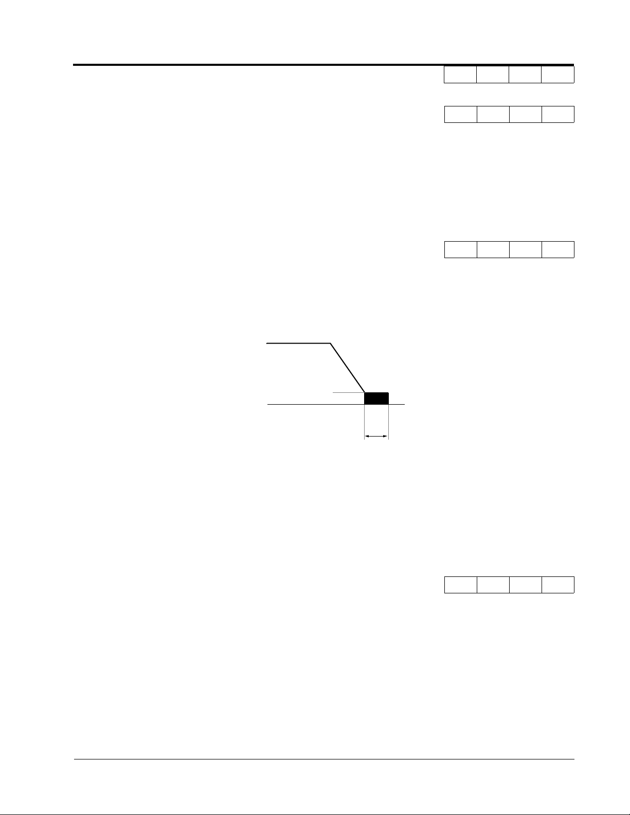
B1-03 Stopping Method Selection Stopping Method
This function selects the stopping method suitable for the particular application.
Setting Description
0 Ramp to stop (factory default)
1 Coast to stop
2 DC injection to stop
3 Coast to stop with timer
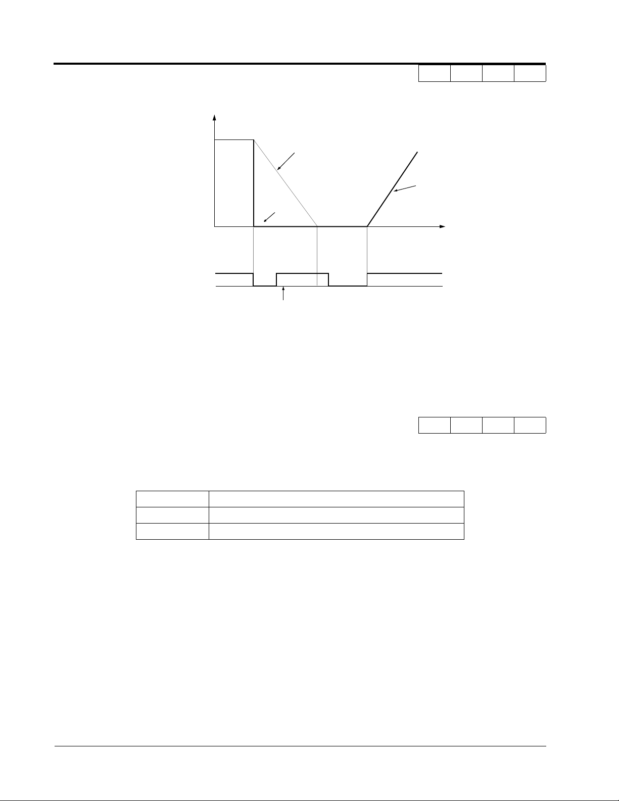
· Ramp to Stop (B1-03 = “0”)
Output Frequency
Decel time 1 (C1-02)
Zero Speed Level (Frequency at
DC Injection Braking Start - B2-01)
Factory Default: 0.5Hz
DC injection Braking Time
at Stop (B2-04)
Factory Default: 0.5 s
Run Command
ON
OFF
Q Q Q Q
Figure 1 Stopping Method - Ramp to Stop
Upon removal of the FWD (REV) run command, the motor decelerates at a rate determined by the
time set in deceleration time 1 (C1-02) and DC injection braking is applied after the minimum output
frequency (E1-09) has been reached. If the deceleration time is set too short or the load inertia is large,
an overvoltage fault (OV) may occur during deceleration. In this case, increase the deceleration time or
install an optional braking transistor and/or braking resistor (braking transistors are provided as standard for units 230V 7.5kW and smaller, 460V 15kW and smaller).
Braking torque: without braking resistor, approx. 20% of motor rated torque
with braking option, approx. 150% of motor rated torque
12 VS-616G5 Programming Manual
Page 13

· Coast to Stop (B1-03 = “1”)
Section B: Application Parameters
B1 Sequence
V/f V/f w/PG
Open Loop
Vector
Flux
Vector
Output frequency
Run command
ON
Inverter output is shut OFF
when stop command is given.
OFF
Figure 2 Stopping Method - Coast to Stop
Upon removal of the FWD (REV) run command, the motor starts to coast. After a stop command is
given, a run command is accepted and operation will start after the minimum baseblock time (L2-03)
elapses. If there is a possibility that a run command might be entered before the motor has come to a
stop, the speed search function (B3) or Coast to Stop with Timer 1 (B1-03 = “3”) should be employed.
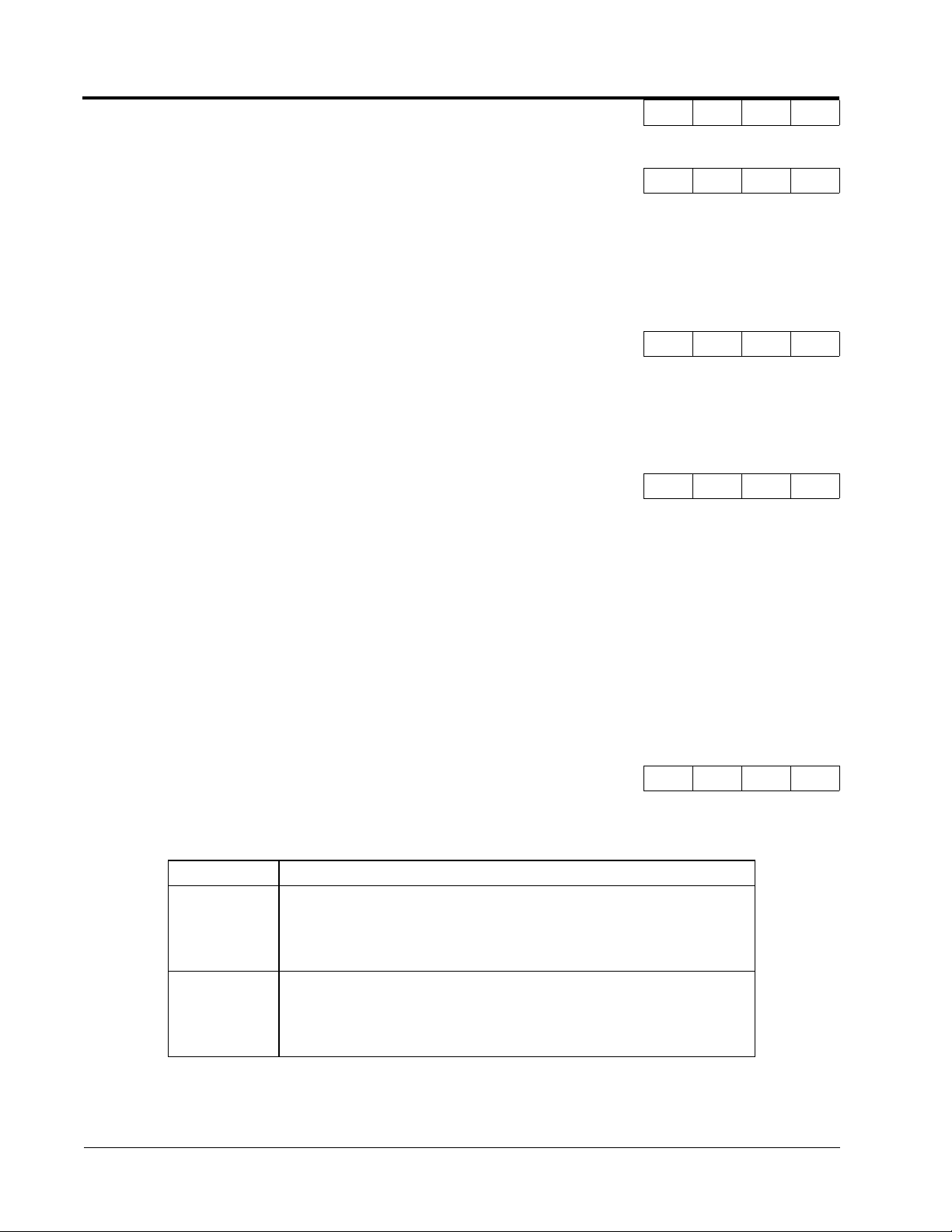
· DC Injection Braking to Stop (B1-03 = “2”)
Output Frequency
Inverter Output OFF during
Minimum Baseblock Time (L2-03)
Factory Default: 0.5s
Run Command
ON
DC injection Braking Time
at Stop (B2-04)
Factory Default: 0.0s
OFF
DC injection
Braking Time
DC injection Braking Time
at Stop (B2-04)
B2-04 x 10
Figure 3 Stopping Method - DC Injection Braking to Stop
Upon removal of the FWD (REV) run command, the motor brakes to stop, according to the DC injection braking time at stop set in B2-04. If this value is set to “0” (factory default), DC injection braking
is disabled, and the motor coasts to stop. When choosing this function, note that the actual stop time is
the time set in B2-04 multiplied by 10 (see Figure 3 above). This stopping method is disabled during
flux vector control. Braking duty cycle should allow excess motor heat to dissipate.
VS-616G5 Programming Manual 13
Page 14
Section B: Application Parameters
B1 Sequence
· Coast to Stop with Timer 1 (B1-03 = “3 ”)
V/f V/f w/PG
Open Loop
Vector
Flux
Vector
Output Frequency
Coasting
FWD (REV)
Run Command
Run Command Disabled
Decel Time 1
(C1-02)
Figure 4 Stopping Method - Coast to Stop w/ Timer
After a stop command is given, a run command is not accepted while the coast to stop timer elapses
(same as Decel 1). After the timer runs out, another run command must be given for the inverter to
begin acceleration. This stopping method is disabled during flux vector control.
B1-04 Prohibition of Reverse Operation Reverse Oper
Accel Time 1
(C1-01)
Time
ONONON
B B B B
A “reverse run disabled” setting does not allow a reverse run command from the control circuit terminal or the digital operator. This setting is used in applications where a reverse run command is undesirable.
Setting Description
0 Reverse run enabled (factory default)
1 Reverse run disabled
14 VS-616G5 Programming Manual
Page 15
Section B: Application Parameters
B1 Sequence
V/f V/f w/PG
Open Loop
Vector
Flux
Vector
B1-05 Operation Selection at Zero Speed Zero Speed Oper
During flux vector control, select an operation mode to be employed when the frequency reference (analog input) drops below the minimum output frequency (El -09). During V/f or open loop vector control,
baseblock is applied when the output frequency drops below the minimum output frequency (El -09).
Setting Description
0 E1 -09 disabled, run according to frequency reference (factory default)
1 Baseblock
2 Run at minimum output frequency (E1-09)
3 Zero-speed operation (internal speed reference is set to “0”)
B1-06 Input Scan Time Cntl Input Scans
This parameter selects the microprocessor scan time for reading sequence input data from the control
circuit terminals.
Setting Description
0 2ms scan time for 2 scans
1 5ms scan time for 2 scans (factory default)
- - - A
B B B B
Set to “0” when a quicker response is needed from the control circuit terminals.
B1-07 Operation Selection After Switch to Remote Mode LOC/REM RUN Sel
Parameter b1-07 determines how the inverter will function when switching between local and remote
operation. This function prevents the motor from running when switching between local/remote and
the inverter is controlled from the digital operator.
Setting Description
0 (Cycle Extrn RUN) - If the run command is closed when switching from local control to remote control,
the inverter will not run. The run command must be cycled for the inverter to run. (factory default)
1 (Accept Extrn RUN) - If the run command is closed, when switching from local control to remote con-
trol, the inverter will run.
A A A A
VS-616G5 Programming Manual 15
Page 16

Section B: Application Parameters
B2 DC Braking
V/f V/f w/PG
Open Loop
Vector
Flux
Vector
B1-08 Run Command Acceptance During Programming RUN CMD at PRG
As a safety precaution the drive will not respond to a change in the run command when the digital
operator is being used to set or adjust parameters.This parameter will allow the drive to accept or
reject a change in the run command when the digital operator is being used to change or adjust parameters. <1110>
Table 1:
Setting Description
0 Run command is disabled when drive is in the programming mode. (factory default)
1 Run command is enabled when the drive is in the program mode
B2 DC Braking
B2-01 DC Braking Frequency (Zero Speed Level) DCInj Start Freq
Setting Range: 0.0 to 10.0Hz
Factory Default: 0.5Hz
Sets the frequency at which DC injection braking (or initial excitation for flux vector control) starts, in
units of 0.1 Hz. When B2-01 < E1-09, DC injection braking starts from the minimum frequency reference (E1-09).
A A A A
B B B B
B2-01
DC Injection
Braking Frequency
B2-03
DC Injection Braking
Time at Start
Figure 5 DC Injection Braking at Starting
B2-02 DC Braking Current DCInj Current
Setting Range: 0 to 100%
Factory Default: 50%
DC injection braking current is set as a percentage of inverter rated current. In flux vector control
mode, initial excitation is performed according to the motor no-load current set in E2-03. This param-
eter should not be set unnecessarily high or motor overexcitation may occur.
B B B -
16 VS-616G5 Programming Manual
Page 17
Section B: Application Parameters
B2 DC Braking
V/f V/f w/PG
Open Loop
Vector
Flux
Vector
B2-03 DC Braking Time at Start DCInj Time@Start
Setting Range: 0.00 to 10.00s
Factory Default: 0.00s
DC injection braking at start can be used to stop a spinning motor (or when motor rotation direction is
unknown) prior to running. DC injection braking time at start (or initial excitation for flux vector control) is set in units of 0.1 second. When B2-03 is set to “0”, DC injection braking is disabled and acceleration starts from the minimum output frequency.
B2-04 DC Braking Time at Stop DCInj Time@Stop
Setting Range: 0.00 to 10.00s
Factory Default: 0.00s
DC injection braking time at stop (or initial excitation for flux vector control) is set in units of 0.1 second. When B2-04 is set to “0”, DC injection braking is disabled, and the inverter output shuts OFF.
E1-09
Min. Output Frequency
B B B B
B B B B
B2-04
DC injection Braking
Time at Stop
Figure 6 DC Injection Braking Time at Stop
When coast to stop is selected as the stopping method (B1-03), DC injection braking at stop is disabled.
B2-08 Magnetic Flux Compensation Level <1110> FieldComp
Setting Range: 0 to 500%
Factory Default: 0%
This parameter allows the magnetizing motor flux to be boosted when starting the motor. This parameter
will facilitate a quick ramp-up of the torque reference and magnetizing current reference to reduce motor
slip during start. A setting of 100% equals motor no-load current E1-09. This flux level will be applied
below Minimum Output Frequency (E1-09) until the DC Injection Time at Start (B2-03) expires. This
parameter is useful when starting motors that are relatively larger than the inverter, due to the requirement
for increased magnetizing current. This parameter may also compensate for reduced starting torque due to
motor circuit inefficiencies.
- - A A
VS-616G5 Programming Manual 17
Page 18

Section B: Application Parameters
B3 Speed Search
B3 Speed Search
When starting into a coasting motor, use the speed search command or DC injection braking at start, to
prevent a drive trip and motor burnout.
This function allows the restart into a coasting motor without the necessity to stop. It is useful during
inverter bypass operation, when switching between the motor receiving power directly from the line
and from the inverter. Two interlocking contactors must be employed for commercial power switchover to prevent line power from being applied to the inverter output terminals.
Set the multi-function contact input selection (H1-01 to H1-06) to “61” (start search command from
maximum output frequency), “62” (start search command from the set frequency), or “64” (start
search command from the SFS frequency when baseblock is applied).
V/f V/f w/PG
Open Loop
Vector
Flux
Vector
B3-01 Speed Search after Run Command SpdSrch at Start
A - A -
Setting Description
0 Speed search disabled, the motor accelerates to the set frequency from the
min. frequency reference after run command is given (factory default).
1 Speed search enabled after run command is given, according to multi-func-
tion contact input selection. When using an encoder, the motor accelerates/
decelerates to the set frequency from the motor speed.
Note: This parameter is disabled except when (A1-02=1) (V/F w/PG Fdbk) or 3 (Flux Vector)
B3-02 Speed Search Detection Current Level SpdSrch Current
Setting Range: 0 to 200%
Factory Default: 150%
After power loss and recovery, speed search begins to ramp the frequency down from a specified point in
order to locate the frequency of the spinning motor. During initial speed search the inverter’s output current exceeds the speed search detection current level. This level is set as a percentage of inverter rated
current. When the inverter’s output current is less than the speed search detection level, the frequency is
interpreted as the speed agree level, and the inverter accelerates/decelerates to the specified frequency.
A - A -
Note: Factory setting defaults to 150 when A1-02=0 (V/F Control). When A1-02=2 (Open Loop Vec-
tor), the default is 100.
18 VS-616G5 Programming Manual
Page 19

Section B: Application Parameters
B4 Delay Timers
V/f V/f w/PG
Open Loop
Vector
Flux
Vector
B3-03 Speed Search Deceleration Time SpdSrch Dec Time
Setting Range: 0.1 to 10.0s
Factory Default: 2.0s
Sets deceleration time during speed search in units of 0.1 second. When speed search deceleration time
is set to 0.0 second, speed search is disabled. The speed search deceleration time should be set to be
somewhat faster than the decel rate of coasting motor. Build an input sequence so that the speed search
command is input at the same time or prior to the FWD (REV) run command. If the run command is
input before the search command, the search command is not effective. Below is a timing diagram of
the search command input:
FWD (REV) Run Command
Speed Search Command
Max. Output Frequency,
Frequency Reference at
Run Command Input,
or SFS Output Frequency
Output Frequency
Motor Speed
ON
Min. Baseblock
Time (L2-03)
Speed Search
Decel Time (B3-03)
Speed Search
Operation
Coasting Accelerating
ON
A - A -
B3-02
Figure 7 Search Command Input Timing Diagram
B4 Delay Timers
The inverter input and output contacts can be used in place of an external timer. When multi-function
contact input (H1-__ = “18”) is closed, a multi-function contact output (H2-__ = “12”) can be set to
close after the On-delay time (B4-01) has expired. When multi-function contact input (H1-__ = “18”)
is opened, a multi-function contact output (H2-__ = “12”) can be set to open after the Off-delay time
(B4-01) has expired. This function operates independently of any action the inverter is performing.
B4-01 On-delay Timer Delay-ON Timer
Setting Range: 0.0 to 100.0s
Factory Default: 0.0s
Sets the ON-delay time in units of 0.1 second. The multi-function input must be “closed” for longer
than the ON-delay timer for the multi-function output to close.
Speed Agree Detected
Output Current
A A A A
VS-616G5 Programming Manual 19
Page 20

Section B: Application Parameters
B5 PID Control
V/f V/f w/PG
Open Loop
Vector
Flux
Vector
B4-02 Off-delay Timer Delay-OFF Timer
Setting Range: 0.0 to 100.0s
Factory Default: 0.0s
Sets the OFF-delay time in units of 0.1 second. The multi-function input must be “open” for longer
than the OFF-delay timer for the multi-function output to open.
Multi-function Contact
Input: Timer Function
Multi-function Contact
Output: Timer Function
B4-01
ON
ON
B4-02
ON ON ON
B4-01 B4-02
Figure 8 Timing Diagram of Timer Function
B5 PID Control
The Proportional, Integral and Derivative (PID) control function provides closed-loop control and regulation of a system variable such as temperature or pressure. A control signal based on the difference
(or proportion) between a feedback signal and a desired setpoint is produced. Integration and derivative calculations are then performed on this signal, based upon the PID parameter settings (B5-01 to
B5-08), to minimize deviation, for more precise control.
A A A A
ON
ON ON ON
ON
Proportional - P
PID refers to the type of action used to control modulating equipment such as valves or dampers. With
proportional control, a control signal based on the difference between an actual condition and a
desired condition is produced. The difference, such as that between an actual temperature and setpoint
is the “error”. The inverter adjusts its output signal related directly to the error magnitude.
Integral - I
The integral action is designed to minimize offset. An integrating term is used to observe how long the
error condition has existed, summing the error over time. Once the system has stabilized, the offset
would be minimized.
Derivative - D
Overshoot refers to a control loop tendency to overcompensate for an error condition, causing a new
error in the opposite direction. Derivative action provides an anticipatory function that exerts a “braking” action on the control loop. When combined, the proportional integral, and derivative actions provide quick response to error, close adherence to the setpoint, and control stability.
20 VS-616G5 Programming Manual
Page 21

Section B: Application Parameters
Figure 9 PID Block Diagram
VS-616G5 Programming Manual 21
Figure 9 PID Block Diagram
Page 22
Section B: Application Parameters
B5 PID Control
V/f V/f w/PG
Open Loop
Vector
Flux
Vector
B5-01 PID Control Mode Selection PID Mode
To enable PID control, set PID control mode selection to “1” or “4”, according to the description
below. Also be sure to set terminal 16 function selection (H3-05) to PID feedback (setting: “B”).
Setting Description
0 PID disabled (factory default)
1 PID enabled (deviation signal is put through derivative control)
2 PID with feed forward (feedback signal is put through derivative control)
3 <1110> Reference= Frequency reference + PID output, D is Fdbk
4 <1110> Reference= Frequency reference + PID output, D is feed-forward
Notes:
1. PID with feed forward applies control much quicker than normal PID, without waiting for
the deviation signal to build up.
2. A PID inverse feedback signal can be selected by inverting the settings for terminal 16
gain and bias.
Then select the PID control intended value setpoint or detected feedback value setpoint as follows:
Intended Value Setting
The control circuit terminal 16 voltage signal (0 to 10V, -10 to 10V) or multi-step speed parameters H103 to H1-06 can be used to set the PID intended value.
A A A A
Control circuit terminal 16 voltage signal:
Set reference selection (B1-01) to “1”.
Multi-step speed parameters (H1-03 to H1-06):
Set reference selection (B1-01) to “0”.
(combination of multi-step speed references and jog frequency reference)
Detected Value Setting (Feedback)
The control circuit terminal 14 current signal (4 to 20mA) or voltage signals (0 to 10V, -10 to 10V) can
be used to set the PID detected value.
Control circuit terminal 14 current signal:
Set terminal 14 signal selection (H3-08) to “2”.
Control circuit terminal 14 voltage signal:
Set terminal 14 signal selection (H3-08) to “0”or “1”.
22 VS-616G5 Programming Manual
Page 23

Notes:
1. I value is reset to ”0” when operation stops.
2. The upper limit of the I value can be set by parameter B5-04.
Increase the value of parameter B5-04 to upgrade control capability by integration. If the control
system vibrates and it cannot be stopped by adjusting the integral time, output delay time, etc.,
decrease the set value of parameter B5-04.
3. PID control can be canceled by a multi-function contact input signal.
By setting any of parameters H1-01 to H1-06 to “19” and by closing the contact during running,
PID control is disabled and the intended value signal itself is used as a frequency reference signal.
Section B: Application Parameters
B5 PID Control
V/f V/f w/PG
Open Loop
Vector
Flux
Vector
B5-02 PID Control Proportional Gain PID Gain
Setting Range: 0.00 to 25.00
Factory Default: 1.00
The proportional gain is the value by which the deviation signal is multiplied to generate a new frequency reference.
B5-03 PID Control Integral Time PID I Time
Setting Range: 0.00 to 360.0 seconds
Factory Default: 1.00 seconds
The integral calculation sums the deviation over time, which eliminates the offset, thus achieving the
intended value. The integral time determines how quickly the integral gain increase is added to the
control loop.
B5-04 PID Control Integral Limit PID I Limit
Setting Range: 0.0 to 100.0%
Factory Default: 100.0%
The integral limit value eliminates oscillations and improves stability. This value is set as a percentage
of maximum output frequency (E1-04).
A A A A
A A A A
A A A A
B5-05 PID Control Derivative Time PID D Time
A A A A
Setting Range: 0.00 to 10.00 seconds
Factory Default: 0.00 seconds
The derivative calculation attempts to control the remaining overshoot left over after the proportion
and integral calculations. If the system is approaching the intended value very rapidly, the derivative
control produces a strong braking action to prevent overshoot. If the system is already stable with very
little deviation change, derivative control has very little effect. The derivative time is used to dampen
oscillations and reduce overshoot, thus improving stability. Setting the derivative time to a larger number produces more braking action in the control system.
VS-616G5 Programming Manual 23
Page 24
Section B: Application Parameters
B5 PID Control
V/f V/f w/PG
Open Loop
Vector
Flux
Vector
B5-06 PID Control Limit PID Limit
Setting Range: 0.0 to 100.0%
Factory Default: 100.0%
The PID limit value further eliminates oscillations and improves stability. This value is set as a percentage of maximum output frequency (E1-04).
B5-07 PID Control Offset PID Offset
Setting Range: -100.0% to +100.0%
Factory Default: 0.0%
The PID offset adds a bias to the calculated PID value, in order to reduce any offset.
B5-08 PID Control Output Primary Delay Time PID Delay Time
Setting Range: 0.00 to 100.0 seconds
Factory Default: 0.00 seconds
The output delay time is used to delay changes in the calculated PID value, which can prevent oscillations and improve stability.
A A A A
A A A A
A A A A
Parameters B5-04 and B5-06 to B5-08 are preset at the factory to optimum values for most applications, hence, do not need to be changed. When tuning a system, first adjust the proportional gain until
oscillations are reduced. Then adjust the integral time so that minimal deviation is achieved as quickly
as possible, without oscillations. Finally, adjust the derivative time to reduce any overshoot at start-up.
B5-09 PID Output Selection <1110> Output Level Sel
The PID output term for the inverter control can be either negative or positive output.
Setting Description
0 PID Normal or Forward Output (factory default)
Increase in the manipulated variable when the process variable is larger than
the setpoint and decrease the manipulated variable when the process variable is smaller.
1 PID Reverse or Inverse Output
Increase the manipulated variable when the process variable is smaller than
the setpoint and decrease the manipulated variable when the process variable is larger than the setpoint.
A A A A
24 VS-616G5 Programming Manual
Page 25

Section B: Application Parameters
B5 PID Control
V/f V/f w/PG
Open Loop
Vector
Flux
Vector
B5-10 PID Output Gain <1110> Output Gain
Setting Range: 0.0 to 25.0
Factory Default: 1.0
This parameter sets the gain of the PID output. The PID output can be monitored by parameter U1-37
PID Output Monitor. Refer to PID Block Diagram Figure 9.
B5-11 PID Output Reverse <1110> Output Rev Sel
This parameter is used when the motor is required to change direction during PID operation in
response to a negative PID output signal. The PID output can be monitored using parameter U1-37
PID Output Monitor.
Setting Description
0 Zero limit (factory default)
When PID output is negative, motor direction is not changed. The PID output
is limited to 0.
1 Reverse
When PID output is negative the motor will reverse direction.
A A A A
A A A A
Note: When Reverse Prohibit B1-04 is selected, reverse will not operate.
B5-12 Loss of Feedback Action <1110> Fb Los Det Sel
This parameter is used to select what action the inverter will take on a loss of PID feedback. A loss of
PID feedback occurs when the feedback signal falls below the B5-13 Feedback Loss Detection Level
for the time set by B5-14 Feedback Loss Detection Time.
Setting Description
0 Disabled (factory default)
PID feedback missing detection is disabled.
1 Alarm
PID feedback missing detection is enabled. Operation continues after loss of
feedback. The text “Fbl” will be displayed on the digital operator.
2 Fault
PID feedback missing detection is enabled. The inverter output to the motor
is shut off (the motor is stopped) and “Fbl” is displayed on the digital operator.
A A A A
VS-616G5 Programming Manual 25
Page 26

Section B: Application Parameters
B6 Reference Hold
V/f V/f w/PG
Open Loop
Vector
Flux
Vector
B5-13 PID Feedback Loss Detection Level <1110> Fb los Det Lvl
Setting Range: 0 to 100%
Factory Default: 1%
This parameter sets the level at which a loss of PID feedback is detected. The PID feedback must be at
or below this level for the time defined by B5-14 before a loss of feedback can be detected. A setting
of 100% represents 100% of the feedback signal.
B5-14 PID Output Gain <1110> Output Gain
Setting Range: 0.0 to 25.0
Factory Default: 1.0
This parameter sets the gain of the PID output. The PID output can be monitored by parameter U1-37
PID Output Monitor. Refer to PID Block Diagram Figure 9.
B6 Reference Hold
The reference hold or dwell function is used to temporarily hold the output frequency at a set reference, for a set time, and then start it again. This function can be used when driving a permanent magnet
motor, or a motor with a heavy starting load. This pause in acceleration allows the magnets in a permanent magnet motor to synchronize with the stator field of the motor, thus reducing traditionally high
starting current.
A A A A
A A A A
B6-01 Dwell Frequency Reference at Start Dwell Ref @Start
Setting Range: 0.0 to 400.0Hz
Factory Default: 0.0Hz
Sets the dwell frequency reference during acceleration in units of 0.1Hz.
B6-02 Dwell Time at Start Dwell Time@Start
Setting Range: 0.0 to 10.0s
Factory Default: 0.0s
Sets the amount of time that the frequency reference “dwells” during acceleration in units of 0.1s.
B6-03 Dwell Frequency Reference at Stop Dwell Ref @Stop
Setting Range: 0.0 to 400.0Hz
Factory Default: 0.0Hz
Sets the dwell frequency reference during deceleration in units of 0.1Hz.
A A A A
A A A A
A A A A
26 VS-616G5 Programming Manual
Page 27

Section B: Application Parameters
B7 Droop Control and B8 Energy Saving
V/f V/f w/PG
Open Loop
Vector
Flux
Vector
B6-04 Dwell Time at Stop Dwell Time @Stop
Setting Range: 0.0 to 10.0s
Factory Default: 0.0s
Sets the amount of time that the frequency reference “dwells” during deceleration in units of 0.1s.
B7 Droop Control
The Drooping function reduces the motor speed based on the load torque of the motor.
B7-01 Droop Control Gain Droop Quantity
Setting Range: 0.0 to 100.0
Factory Default: 0.0
Parameter b7-01 sets the amount of motor speed reduction when the motor is producing 100% of rated
torque. The actual amount of motor speed reduction is based on the ratio of the amount of motor
torque and the maximum output frequency (E1-04).
B7-02 Droop Control Delay Time Droop Delay Time
Setting Range: 0.03 to 2.00
Factory Default: 0.05
A A A A
- - - A
- - - A
Parameter b7-02 sets the response time for the drooping function. Decreasing the droop delay time,
will cause the response to become quicker; however, instability may occur.
B8 Energy Saving
This feature can save energy during operation under lightly loaded conditions, by decreasing output
voltage, energy-saving operation is made available. Energy saving control is enabled by a multi-func-
tion contact input, when control mode selection (A1-02) is set to “0” (V/f Control) or “1” (V/f w/PG
Fdbk).
Parameters B8-03, B8-04 and B8-05 are for energy savings in the vector modes. B8-01 and B8-02 are
only functional in the V/f modes via a multi-function input command. Parameters B8-03, B8-04 and
B8-05 are for automatic energy savings in the vector modes.
B8-01 Energy Saving Gain Energy Save Gain
Setting Range: 0 to 100%
Factory Default: 80%
The output voltage during energy-saving operation is the product of the normal V/f settings (El-03 to
E1-10) and the energy saving gain. The output voltage decreases and recovers in the voltage recovery
time (L2-04). As the energy saving gain increases, the output voltage increases also. This feature is
only enabled by a multi-function contact input.
A A - -
VS-616G5 Programming Manual 27
Page 28

Section B: Application Parameters
B8 Energy Savings
V/f V/f w/PG
Open Loop
Vector
Flux
Vector
B8-02 Energy Saving Starting Frequency Energy Save Freq
Setting Range: 0.0 to 400.0Hz
Factory Default: 0.0Hz
After the multi-function contact input for energy-saving operation closes (H1-__, setting: “63”), the
output voltage is decreased when the output frequency reaches the energy-saving starting frequency.
This feature is only enable by multi-function contact input.
.
B8-03 Automatic Energy Saving <1110> Energy Save Sel
This parameter is used to select if Automatic Energy Saving Mode is to be on or off. A multi-function
contact input is not required to activate Automatic Energy Saving Mode. This mode of operation automatically searches for the optimum motor voltage required to save energy. This function is separate
and not to be confused with parameters B8-01 and B8-02. The energy saving mode that utilizes B8-01
and B8-02 requires a multi-function input to be activated for operation. This Automatic Energy Saving Mode selection does not require a multi-function input to activate operation.
Setting Description
0 Disabled (factory default)
Energy saving mode will not be activated under light loads.
1 Enabled
The energy saving mode will be activated under light loads.
A A - -
- - A A
B8-04 Energy Saving Control Gain Energy Save Gain
Setting Range: 0 to 10.0
Factory Default: 0.7
The output voltage during energy-saving operation is the product of the normal V/f settings (El-03 to
E1-10) and the energy saving gain. The output voltage decreases and recovers according to the EnergySaving Control Time Constant B8-05. As the energy saving gain increases, the output voltage
increases also.
Note: When the control mode A1-02=3, the default factory setting becomes 1.0
B8-05 Energy Control Time-Constant Energy Save F. T
Setting Range: 0.00 to 10.00
Factory Default: 0.50
Parameter B8-05 sets the response time for the Automatic Energy Saving function.
Decreasing the Energy Control Time-Constant, will cause the response to become quicker; however,
instability may occur if this is decreased too much.
Note: When control mode A1-02=3, the default factory setting becomes 0.01.
- - A A
- - A A
28 VS-616G5 Programming Manual
Page 29

FWD
Energy
Saving
Command
(Multi-function input
setting = “63”)
Fout
Section B: Application Parameters
B9 Zero Servo
V/f V/f w/PG
Fref ≥ B8-02
Open Loop
Vector
Flux
Vector
Vout
L2-04
V/f Pattern × Energy Saving Gain (B8-01)
Figure 10 Timing Diagram of Energy Saving Function
B9 Zero Servo
The zero servo function is enabled when the multi-function contact input is set to zero servo command
(H1-__ = “72”). The motor position is then memorized when motor speed feedback is less than the
zero speed level (B2-01).
B9-01 Zero Servo Gain Zero Servo Gain
Setting Range: 0 to 100
Factory Default: 5
Sets the zero-servo position loop gain. When adjusting the gain, the higher the setting, the quicker the
response. However, if the gain is set too high, it can cause overshoot and a possible runaway condition.
B9-01
Kp
∫
Deviation
Counter
Speed Reference
Motor Speed Feedback
0
(Position Ref.)
+
-
Motor
Position
- - - A
Figure 11 Zero Servo Position Loop
B9-02 Zero Servo Bandwidth Zero Servo Count
- - - A
Setting Range: 0 to 16383 pulses
Factory Default: 10 pulses
Sets zero servo bandwidth in units of one pulse. During zero servo control, the multi-function contact
output (H2-__ = “33”) is closed until the number of pulses (or bandwidth) is completed. Then the contact output opens.
VS-616G5 Programming Manual 29
Page 30

Section C: Tuning Parameters
C1 Accel/Decel
.
V/f V/f w/PG
Open Loop
Vector
Flux
Vector
Zero Servo Function
(Multi-function Input
H1-__ setting = “72”)
Zero Servo Completion
(Multi-function Output
H2-__ setting = “33”)
Notes:
1. For multi-function contact input function selection, refer to parameters H1-01 to H1-06.
2. For multi-function contact output function selection, refer to parameters H2-01 to H2-03.
3. This function is only available during flux vector control (Al-02 = “3”).
C Tuning Parameters
C1 Accel/Decel
OFF
(Factory Default: 0.5Hz)
Zero Servo Loop
ON
Motor Speed
Zero Servo Bandwidth
Position Deviation
ON
Zero Speed Level
(B2-01)
Speed Loop
(B9-02)
OFF
Figure 12 Timing Diagram of Zero Servo Function
C1-01 Acceleration time 1 Accel Time 1
C1-02 Deceleration time 1 Decel Time 1
C1-03 Acceleration time 2 Accel Time 2
C1-04 Deceleration time 2 Decel Time 2
C1-05 Acceleration time 3 Accel Time 3
C1-06 Deceleration time 3 Decel Time 3
C1-07 Acceleration time 4 Accel Time 4
C1-08 Deceleration time 4 Decel Time 4
Setting Range: 0.00 to 6000.0s
Note: Setting range may be 0.00-600.0 or 0.0-6000.0 depending on the setting of parameter C1-10.
Factory Default: 10.0s
Acceleration time sets the time necessary for the output frequency to accelerate from 0Hz to maximum
output frequency. Deceleration time sets the time necessary for the output frequency to decelerate from
the maximum output frequency to 0Hz.
Q Q Q Q
Q Q Q Q
B B B B
B B B B
A A A A
A A A A
A A A A
A A A A
30 VS-616G5 Programming Manual
Page 31

Section C: Tuning Parameters
C1 Accel/Decel
V/f V/f w/PG
Open Loop
Vector
Flux
Vector
Accel Time 1
(C1-01)
Output
Frequency
FWD (REV) Run Command
Accel/Decel Time Selection 1
(Terminals 3 to 8, Setting = “7”)
Accel/Decel Time Selection 2
(Terminals 3 to 8, Setting = “1A”)
* When “deceleration to stop” is selected (B1-03 = “0”)
Decel Time 1* (C1-02)
Accel Time 2 (C1-03)
ON OFF ON
Figure 13 Timing Diagram of Accel/Decel Time Adjustment
ON
Decel Time 2*
(C1-04)
Decel Time 1*
(C1-02)
Accel Time 3
(C1-05)
ON OFF ON
OFF
Decel Time 3* (C1-06)
Accel Time 4 (C1-07)
ON
ON
Decel Time 4*
(C1-08)
Decel Time 1*
(C1-02)
Time
When any of the multi-function contact input selections (H1-01 to H1-06) are set to “7”and “1A”, up to
four accel/decel times can then be selected by opening or closing the appropriate accel/decel time selection
commands (terminals 3 to 8).
.
Accel/decel Time
Selection 1
Multi-function Input
Setting = “7”
Accel/decel Time
Selection 2
Multi-function Input
Setting = “1A”
Accel Time Decel Time
Open or not set Open or not set C1-01 C1-02
Closed Open or not set C1-03 C1-04
Open or not set Closed C1-05 C1-06
Closed Closed C1-07 C1-08
C1-09 Fast-Stop Time Fast Stop Time
Setting Range: 0.00 to 6000.0s
Factory Default: 10.0s
Fast-stop time is enabled when:
Multi-function contact input is set to fast-stop command (setting = “15”), and the contact closes.
The default stopping method when a fault is detected is fast-stop.
B B B B
VS-616G5 Programming Manual 31
Page 32

Section C: Tuning Parameters
C2 S-Curve Accel/Decel
V/f V/f w/PG
Open Loop
Vector
Flux
Vector
C1-10 Accel/Decel Time Setting Unit Acc/Dec Units
Setting Description
0 Accel/decel time (C1-01 to C1-09) setting range is in units of 0.01 second.
Accel/decel time setting range: 0.00 to 600.00s
1 Accel/decel time (C1-01 to C1-09) setting range is in units of 0.1 second.
Accel/decel time setting range: 0.0 to 6000.0s (factory default)
If any of the parameters C1-01 to C1-09 is set to 600.1 seconds or more, C1-10 cannot be set to “0”.
C1-11 Accel/Decel Time Switching Frequency Level Acc/Dec SW Freq
Setting Range: 0.0 to 400.0Hz
Factory Default: 0.0Hz
Accel/decel times can be changed automatically, without using the multi-function contact inputs.
Use accel/decel times set in parameters C1-01 and C1-02 when output frequency ≥ C1-11.
Use accel/decel times set in parameters C1-07 and C1-08 when output frequency < C1-11.
When multi-function contact inputs are set for accel/decel selection, this command has priority over
automatic change of accel/decel.
Accel/Decel Switching Level
(C1-11)
A A A A
A A A A
Output Frequency
C1-07
C1-01 C1-02 C1-08
Figure 14 Accel/Decel Switching Level Adjustment
C2 S-Curve Accel/Decel
An S-curve pattern is used to reduce shock and provide smooth transitions during machine acceleration and deceleration. S-curve characteristic time is the time from the output frequency to the set accel/
decel time.
C2-01 S-Curve Time at Acceleration Start SCrv Acc @ Start
C2-02 S-Curve Time at Acceleration End SCrv Acc @ End
C2-03 S-Curve Time at Deceleration Start SCrv Dec @ Start
C2-04 S-Curve Time at Deceleration End SCrv Dec @ End
Setting Range: 0.00 to 2.50s
Factory Default: 0.20s
A A A A
A A A A
A A A A
A A A A
32 VS-616G5 Programming Manual
Page 33

Section C: Tuning Parameters
C2 S-Curve Accel/Decel
V/f V/f w/PG
.
Open Loop
Vector
Flux
Vector
Frequency Reference
Output Frequency
S-curve Characteristic
Time (Tsc)
Output Frequency
Time
Figure 15 S-curve Characteristic Timing Diagram
The following figure shows FWD/REV run switching during deceleration to stop.
FWD Run Command
REV Run Command
C2-02 C2-03
C2-04
Output Frequency
C2-01
DC Injection Braking
Time at Stop
B2-04
Figure 16 S-curve Characteristics - FWD/REV Operation
Time to accelerate from the minimum frequency
to the maximum frequency (total acceleration)
C2-01
C2-04
C2-02 C2-03
= C1-__ + (C2-01 + C2-02)/2
VS-616G5 Programming Manual 33
Page 34

Section C: Tuning Parameters
C3 Motor Slip Compensation
C3 Motor Slip Compensation
As the load becomes larger, the motor speed is reduced and motor slip increases. The slip compensation function keeps the motor speed constant even under varying load conditions.
V/f V/f w/PG
Open Loop
Vector
Flux
Vector
C3-01 Slip Compensation Gain Slip Comp Gain
Setting Range: 0.0 to 2.50
Factory Default: 1.0
This function controls the output frequency in response to the load’s torque demand. Increase the set
value in one tenth (0.1) increments when operating at low speeds; decrease the set value as the motor
speed increases.
During flux vector control, this gain compensates for motor slip causes by changes in temperature.
Normally, this setting does not have to be modified.
Note: Default factory setting will be 0.0 when parameter A1-02=0 [V/F mode]. When parameter A102=2 [Open Loop Vector] or 3 [Flux Vector] the default factory setting will be 1.0.
C3-02 Slip Compensation Primary Delay Time Slip Comp Time
Setting Range: 0 to 10000ms
Factory Default: 200ms
Adjust the slip compensation delay time when motor speed is unstable or speed response is slow.
Increase the set value in 10ms increments when operating at low speeds; decrease the set value as the
motor speed increases.
B - B B
A - A -
C3-03 Slip Compensation Limit Slip Comp Limit
A - A -
Sets the slip compensation limit as a percentage of motor rated slip (E2-02).
E1-04
× C3-03
E1-06
C3-03
Output Frequency
Base
Frequency
E1-04E1-06
Maximum
Frequency
Figure 17 Slip Compensation Limit Adjustment
34 VS-616G5 Programming Manual
Page 35

Section C: Tuning Parameters
C3 Motor Slip Compensation
V/f V/f w/PG
Open Loop
Vector
Flux
Vector
C3-04 Slip Compensation During Regeneration Slip Comp Regen
Setting Description
0 Slip compensation disabled during regeneration (factory default)
1 Slip compensation enabled during regeneration
C3-05 Flux Calculation Method Flux Select
Parameter C3-05 determines if the motor torque characteristic is based on output frequency or motor
speed.
Setting Description
0 Slip Included
Motor torque characteristic is based on frequency. (factory default)
1 Slip Excluded
Motor torque characteristic is based on motor speed.
A - A -
- - A -
Torque
100%
=0
=1=0
0%
=1
60Hz 1800 rpm 120Hz 3600 rpm
When running the motor only in the constant torque region, leave parameter C3-05 set to 0 for the
best performance.
When running the motor in the constant horsepower region, set parameter C3-05 to 1 because the
larger flux will result in better motor stability.
VS-616G5 Programming Manual 35
Page 36

Section C: Tuning Parameters
C4 Torque Compensation
V/f V/f w/PG
Open Loop
Vector
Flux
Vector
C3-06 Output Voltage Limit Operation Selection <1110> Output V Limit
Setting Description
0 Disabled (factory default)
When this parameter is “0” slip compensation will be disabled when the motor
is operating above its base speed. The motor voltage will not be reduced
above base speed.
1 Enabled
Open Loop Vector Mode: When this parameter is set to “1” the motor voltage will be reduced slightly when the motor is operating above 90% base
speed. Slip Compensation is enabled. Speed control accuracy is improved.
This may prevent speed instabilities due to motor voltage saturation. This setting may improve speed regulation however motor torque/amp will be
reduced by up to 10% due to motor voltage reduction above base speed.
Flux Vector Mode: Torque linearity is improved.
C4 Torque Compensation
Motor torque can be adjusted by changing the V/f pattern (E1-03) or by adjusting the torque compensation gain. For details on setting the V/f pattern, see section E1, V/f Pattern Adjustment,.
Parameters C4-03, C4-04 and C4-05 are added for the OLV mode to help improve starting/breakaway
response. Individual torque compensation settings are possible for forward (C4-03) and reverse (C4-
04). The delay time (C4-05) is the time for which the internal torque reference will be increased. This
torque compensation is much like inputting an analog torque reference via an analog input.
- - A A
C4-01 Torque Compensation Gain Torq Comp Gain
B B B -
The motor torque requirement changes according to load conditions. Full-range automatic torque boost
adjusts the voltage of the V/f pattern according to the required torque. The VS-616G5 automatically
adjusts the voltage during constant-speed operation as well as during acceleration.
The required torque is calculated by the inverter. This ensures tripless operation and power savings.
36 VS-616G5 Programming Manual
Page 37

Section C: Tuning Parameters
C4 Torque Compensation
V/f V/f w/PG
Open Loop
Vector
Flux
Vector
Output voltage ∝ Torque compensation gain × Required torque
Voltage
Required torque ⇒ Increase voltage
Frequency
Figure 18 Torque Characteristics
Normally, no adjustment is necessary for torque compensation gain. When more torque is needed,
increase the torque compensation gain in one tenth (0.1) increments. When the wiring distance
between the inverter and the motor is long, or when the motor generates excessive vibration, decrease
the torque compensation gain.
Increasing torque compensation gain increases motor torque, but an excessive increase may cause the
following:
· Inverter fault trips due to motor overexcitation
· Motor overheat or excessive vibration
C4-02 Torque Compensation Time Constant Torq Comp Time
Setting Range: 0 to 10000ms
Factory Default: 20ms
Increase the torque compensation time constant in 10ms increments when the motor output current is
unstable, and decrease this value when speed response is slow.
Note: When A1-02=2 [Open Loop Vector] the factory default setting is 20 ms. When A1-02=1or 3
[V/F or V/F w/PG] factory default setting is 200 ms.
C4-03 Forward Torque Compensation Value at Start<1110> F TorqCmp @ start
Setting Range: 0.0 to 200.0%
Factory Default: 0.0
This parameter may improve the motor performance during start. This feature functions only when
starting a motor. Torque reference and motor flux can be ramped up quickly to improve speed
response during start. A setting of 0.0 disables this feature.
A A A -
- - A -
VS-616G5 Programming Manual 37
Page 38

Section C: Tuning Parameters
C5 ASR Tuning
V/f V/f w/PG
Open Loop
Vector
Flux
Vector
C4-04 Reverse Torque Compensation Value at Start<1110> R TorqCmp @ start
Setting Range: 0.0 to 200.0%
Factory Default: 0.0
This parameter may improve the motor performance during start. This feature functions only when
starting a motor. Torque reference and motor flux can be ramped up quickly to improve speed
response during start. A setting of 0.0 disables this feature.
C4-05 Torque Compensation Time Constant@Start<1110> TorqCmp Delay T
Setting Range: 0 to 200 ms
Factory Default: 1 ms
This parameter functions with C4-03 and C4-04. This parameter is the time delay that will be applied
to the Torque Compensation parameters C4-03 and C4-04. A setting of less than 4 milliseconds (ms)
causes this filter to be disabled.
C5 ASR Tuning
The automatic speed regulator (ASR) provides optimum performance during changes in motor speed
or load, when speed feedback is provided.
Frequency Reference
- - A -
- - A -
+
+
Output Frequency
Speed Feedback
Speed Reference
Speed Feedback
+
-
Variation
Ratio Limit
C5-01, C5-03
P
I
C5-02, C5-04
+
Limit
+
C5-05
Figure 19 ASR Block Diagram (V/f Control with PG Feedback)
Torque Limit
Secondary Current Reference
L7-01 ~ L7-04
+
-
C5-01, C5-03
P
I
C5-02, C5-04
+
+
1
1 + ST
C5-06
Figure 20 ASR Block Diagram (Flux Vector Control)
38 VS-616G5 Programming Manual
Page 39

Proportional Gain According to Motor Speed
Section C: Tuning Parameters
C5 ASR Tuning
V/f V/f w/PG
Open Loop
Vector
Flux
Vector
C5-01 ASR Proportional Gain 1 ASR P Gain 1
- B - B
Setting Range: 0.00 to 300.00
Factory Default: 20.00
The ASR proportional gain 1 adjusts the speed in response to speed deviation, and softens the effect of
changes in load. Speed response increases as the proportional gain is increased. However, the load may
become unstable if the ASR proportional gain is set too high.
Note: When parameter A1-02=1 [V/f w/PG] the factory default setting is 0.20. When parameter
A1-02=3 the factory default setting is 20.00.
C5-02 ASR Integral Time 1 ASR I Time 1
- B - B
Setting Range: 0.000 to 10.000s
Factory Default: 0.500s
The ASR integral time 1 adjusts the inverter’s response time to changes in load. Speed response
increases as the integral time is decreased. However, the load may become unstable if the ASR integral
time is set too low.
Note: When A1-02=1 [V/f w/PG] the factory default setting is .200. When A1-02=3 factory default setting is 0.500
When A1-02=1 [V/f w/PG] factory default setting is 0.20. When A1-02=3 factory default setting is 20.00.
When A1-02=1 [V/f w/PG] factory default setting is 0.200. When A1-02=3 factory default setting is 0.500
When A1-02=1 [V/f w/PG] factory default setting is 0.02 When A1-02=3 factory default setting is 20.00.
C5-03 ASR Proportional Gain 2 ASR P Gain 2
- B - B
Setting Range: 0.00 to 300.00
Factory Default: 20.00
The ASR proportional gain 2 is an additional proportional gain adjustment that can be enabled by a
multi-function contact input (H1-__ = “77”).
(see Figure 22)
C5-03 Proportional Gain
Multi-function Input
(H1-__ = “77”)
ON
OFF
C5-02
OFF
ON
C5-02
Figure 21 ASR Multi-function Input Timing Diagram
Note: When parameter A1-02=1 [V/f w/PG] factory default setting is .02 When A1-02=3 the factory
default setting is 20.00.
VS-616G5 Programming Manual 39
Page 40

Section C: Tuning Parameters
C5 ASR Tuning
V/f V/f w/PG
Open Loop
Vector
Flux
Vector
C5-04 ASR Integral Time 2 ASR I Time 2
Setting Range: 0.000 to 10.000s
Factory Default: 0.500s
The ASR integral time 2 is an additional integral time adjustment.
C5-05 ASR Limit ASR Limit
Sets ASR frequency compensation limit as a percentage of maximum output frequency (El -04). This
function is enabled when V/f control with PG feedback is selected as the control method (A1-02).
C5-06 ASR Output Primary Delay Time ASR Delay Time
Setting Range: 0.000 to 0.500s
Factory Default: 0.004s
Mechanical backlash in an application causes secondary current (I2) reference variations in the motor’s
rotor. This condition can prevent the adjustment of ASR parameters.The output delay time constant is
used to control these secondary current (I2) reference variations.
C5-07 ASR Switching Frequency Level ASR Gain SW Freq
Setting Range: 0.0 to 400.0Hz
Factory Default: 0.0Hz
- B - B
- A - -
- - - A
- - - A
Sets frequency to change ASR proportional gain and integral time constant in units of 0.1Hz when flux
vector control is selected.
C5-01
C5-02
C5-03
P gain · I time
0
C5-07
or
E1-04
C5-04
f
FB
Motor Speed
P · N
fFB =
120
where:
P = Number of Motor Poles
N = Motor RPM
* When C5-07 =”0”, proportional gain 1 (C5-01)
and integral time 1 (C5-02) are selected.
Figure 22 ASR Switching Frequency Level
Notes:
1.When C5-07 =”0”, proportional gain 1 (C5-01) and integral time 1 (C5-02) are selected.
2.During V/f control with PG feedback (A1-02 = “1”), the frequency switching level becomes
the maximum output frequency (E1-04).
40 VS-616G5 Programming Manual
Page 41

Section C: Tuning Parameters
C6 Carrier Frequency
V/f V/f w/PG
Open Loop
Vector
Flux
Vector
C5-08 ASR Integral Limit ASR I Limit
Setting Range: 0 to 400%
Factory Default: 400%
.Parameter C5-08 adjusts the amount of Integral control of the automatic speed regulator in the Closed
Loop Flux Vector control mode. Setting parameter C5-08 to zero will make the ASR control propor tional. Setting C5-08 to 400% will make the ASR control proportional and integral.
C5-08=0
P Control
C5-08=400%
P-I Control
Torque
Slip
- - - A
Speed
C6 Carrier Frequency
This function sets the inverter output transistor switching frequency (carrier frequency). Increase the
carrier frequency to reduce motor noise and decrease it to reduce leakage current.
C6-01 Carrier Frequency Upper Limit CarrierFreq Max
C6-02 Carrier Frequency Lower Limit CarrierFreq Min
Setting Range: 0.4 to 15.0kHz
Factory Default: 15.0Hz*
For constant carrier frequency operation, set the gain (C6-03) to “0”, and set the upper limit (C6-01)
and lower limit (C6-02) to the same value.
* Factory defaults vary depending on drive rating. See the following table for more details:
B B B B
A A - -
VS-616G5 Programming Manual 41
Page 42

Section C: Tuning Parameters
C6 Carrier Frequency
Carrier Frequency Factory Defaults
Model
CIMR-
G5U
20P4 15.0 15.0 0 2015 15.0 15.0 0
20P7 15.0 15.0 0 2018 15.0 15.0 0
21P5 15.0 15.0 0 2022 10.0 10.0 0
22P2 15.0 15.0 0 2030 10.0 10.0 0
23P7 15.0 15.0 0 2037 10.0 10.0 0
25P5 15.0 15.0 0 2045 10.0 10.0 0
27P5 15.0 15.0 0 2055 10.0 10.0 0
2011 15.0 15.0 0 2075 10.0 10.0 0
40P4 15.0 15.0 0 4022 8.0 8.0 0
40P7 15.0 15.0 0 4030 8.0 8.0 0
41P5 15.0 15.0 0 4037 6.0 6.0 0
42P2 15.0 15.0 0 4045 6.0 6.0 0
43P7 15.0 15.0 0 4055 6.0 6.0 0
44P0 15.0 15.0 0 4075 6.0 6.0 0
45P5 15.0 15.0 0 4090 5.0 5.0 0
47P5 12.5 12.5 0 4110 5.0 5.0 0
4011 12.5 12.5 0 4132 5.0 5.0 0
4015 10.0 10.0 0 4160 5.0 5.0 0
4018 10.0 10.0 0 4185 2.0 2.0 0
51P5 10.0 10.0 0 5030 10.0 10.0 0
52P2 10.0 10.0 0 5037 10.0 10.0 0
53P7 10.0 10.0 0 5045 10.0 10.0 0
55P5 10.0 10.0 0 5055 8.0 8.0 0
57P5 10.0 10.0 0 5075 2.0 1.0 36
5011 10.0 10.0 0 5090 2.0 1.0 36
5015 10.0 10.0 0 5110 2.0 1.0 36
5018 10.0 10.0 0 5160 2.0 1.0 36
5022 10.0 10.0 0
Upper Limit
C6-01
Setting
- - - - 2090 2.0 2.0 0
- - - - 2185 2.0 2.0 0
- - - - 4220 2.0 2.0 0
- - - - 4300 2.0 2.0 0
Lower Limit
C6-02
Setting
Gain
C6-03
Setting
230
460
575
Model
CIMR-
G5U
Upper Limit
C6-01
Setting
Lower Limit
C6-02
Setting
Gain
C6-03
Setting
42 VS-616G5 Programming Manual
Page 43

Section C: Tuning Parameters
C7 Hunting Prevention
V/f V/f w/PG
Open Loop
Vector
Flux
Vector
C6-03 Carrier Proportional Gain CarrierFreq Gain
Setting Range: 0 to 99
Factory Default: 0
C6-01
Carrier
Frequency
C6-02
Fout × C6-03 × K*
Fout
Output Frequency
* K varies depending on the carrier frequency upper limit (C6-01):
C6-01 > 10.0kHz K = 3
10.0kHz > C6-01 > 5.0kHz K = 2
C6-01 < 5.0kHz K = 1
Figure 23 Carrier Frequency Setting
Note: An OPE11 fault occurs if either of the following conditions is present:
1. C6-03 > 6kHz and C6-02 > C6-01
2. C6-01 > 5kHz and C6-02 ≤ 5kHz
C7 Hunting Prevention
Occasionally, in an application, resonance between the internal control system and the mechanical system causes current instability. This instability is called hunting, and may cause the machine to vibrate
at lower speeds (up to 30Hz). The hunting prevention function monitors the motor flux and uses a special control circuit to “smooth out” any peaks in the output current waveform.
A A - -
C7-01 Hunting Prevention Selection Hunt Prev Select
Enables the hunting prevention function in V/f control mode.
Setting Description
0 Hunting prevention is disabled.
1 Hunting prevention is enabled (factory default).
C7-02 Hunting Prevention Gain Hunt Prev Gain
Setting Range: 0.00 to 2.50
Factory Default: 1.00
Sets hunting prevention gain in units of 0.01. When hunting is present while driving a light load,
increase the set value in one tenth (0.1) increments. When the motor vibrates or stalls while driving a
heavy load, decrease the set value.
A A − −
A A − −
VS-616G5 Programming Manual 43
Page 44

Section C: Tuning Parameters
C8 Factory Tuning
C8 Factory Tuning
This section describes parameters not normally accessed by the user, but which may require adjustment.
V/f V/f w/PG
Open Loop
Vector
Flux
Vector
C8-08 Automatic Frequency Regulator Adjustment AFR Gain
Setting Range: 0.00 to 10.00
Factory Default: 1.00
Sets AFR gain in units of 0.01. When hunting is present during open loop vector control, decrease the
set value in one tenth (0.1) increments. If the speed or torque response is slow, increase the set value.
C8-09 Automatic Frequency Regulator Time Constant AFR Time
Setting Range: 0 to 2000 milliseconds
Factory Default: 50 milliseconds
Parameter C8-09 sets the AFR (automatic frequency regulator) time. Adjusting C8-09 will increase or
decrease the AFR frequency response, when the load changes.
If the motor is unstable, increase the set value.
If the speed response is slow, decrease the set value.
C8-30 Carrier Frequency Selection During Auto-tuning Carrier in Tune
During normal auto-tuning, the inverter is tuned while running at a carrier frequency of 2kHz. This
parameter allows the user to specify the inverter carrier frequency during auto-tuning. Adjustment may
be necessary when using a spindle motor with low inductance.
− − A −
− − A −
− − A A
Setting Description
0 Carrier frequency during auto-tuning is 2kHz (factory default).
1 Carrier frequency during auto-tuning is set by C6-01.
2 Carrier frequency is 5kHz. Except for 185-300 kW which is 2.5 kHz
44 VS-616G5 Programming Manual
Page 45

D Reference Parameters
D1 Preset References
Section D: Reference Parameters
D1 Preset References
V/f V/f w/PG
Open Loop
Vector
Flux
Vector
D1-01 Preset Frequency Reference 1 Reference 1
D1-02 Preset Frequency Reference 2 Reference 2
D1-03 Preset Frequency Reference 3 Reference 3
D1-04 Preset Frequency Reference 4 Reference 4
D1-05 Preset Frequency Reference 5 Reference 5
D1-06 Preset Frequency Reference 6 Reference 6
D1-07 Preset Frequency Reference 7 Reference 7
D1-08 Preset Frequency Reference 8 Reference 8
Setting Range: 0.0 to 400.0Hz
Factory Default: 0.0Hz
Up to 9 preset speed references (including jog) can be set through multi-function contact input function selections. When using the multi-step speed references, set the reference selection (B1-01) to “0”,
and set terminal 16 selection (H3-05) to “1F”. See the following table for programming preset speed
references.
Terminal 5
H1-03 = “3”
Terminal 6
H1-04 = “4”
Terminal 7
H1-05 = “5”
Terminal 8
H1-06 = “6”
Open Open Open Open Speed Reference 1 - Set Reference Source
(B1-01) to “0”.
Closed Open Open Open Speed Reference 2 - Set Terminal 16 Selection
(H3-05) to “1F”.
Open Closed Open Open Speed Reference 3
Closed Closed Open Open Speed Reference 4
Open Open Closed Open Speed Reference 5
Closed Open Closed Open Speed Reference 6
Open Closed Closed Open Speed Reference 7
Closed Closed Closed Open Speed Reference 8
Closed Closed Closed Closed Jog Speed Reference
Q Q Q Q
Q Q Q Q
Q Q Q Q
Q Q Q Q
B B B B
B B B B
B B B B
B B B B
Speed Reference
VS-616G5 Programming Manual 45
Page 46

Section D: Reference Parameters
D1 Preset References
V/f V/f w/PG
Open Loop
Vector
Flux
Vector
D1-09 Jog Frequency Reference JOG Reference
Setting Range: 0.0 to 400.0Hz
Factory Default: 0.0Hz
The jog frequency reference can be set in this parameter. Depress the JOG key on the digital
operator, or close terminal 7, to use this function. The jog command always has priority over
other reference commands. When using the multi-step speed references, change the jog command from terminal 7 to terminal 8 (H1-06 = “6”).
D1-06
50.0Hz
Frequency
Reference
D1-01
10.0Hz
D1-02
20.0Hz
D1-03
30.0Hz
D1-05
45.0Hz
D1-04
40.0Hz
Q Q Q Q
D1-08
60.0Hz
D1-07
55.0Hz
D1-09
6.0Hz
FWD (REV) Run/Stop
Multi-step Speed Ref. 1
(Terminal 5)
Multi-step Speed Ref. 2
(Terminal 6)
Multi-step Speed Ref. 3
(Terminal 7)
Jog Ref.
(Terminal 8)
ON
ON
ON
ON
ON ON
ON
ON
ON
Figure 24 Multi-step Speed Operation - Timing Diagram
Note: Setting units for D1-01 to D1-09 are dependent upon the setting of digital operator display
mode (O1-03). Possible setting units include Hz, percentage, RPM or engineering units. See
section O1, Monitor Selection, on page 120 for more details.
Time
46 VS-616G5 Programming Manual
Page 47

D2 Reference Limits
Section D: Reference Parameters
D2 Reference Limit / D3 Jump Frequency
V/f V/f w/PG
Open Loop
Vector
Flux
Vector
D2-01 Frequency Reference Upper Limit Ref Upper Limit
Setting Range: 0.0 to 110.0%
Factory Default: 100.0%
The frequency reference upper limit is set as a percentage of the maximum output frequency (E1-04)
in increments of 1%.
D2-02 Frequency Reference Lower Limit Ref Lower Limit
Setting Range: 0.0 to 109.0%
Factory Default: 100.0%
The frequency reference lower limit is set as a percentage of the maximum output frequency (E1-04)
in increments of 1%. When a run command is input and the frequency reference is less than the lower
limit, operation continues at the frequency reference lower limit. However, when the lower limit is set
to less than the minimum output frequency (E1-09), operation discontinues.
%
100
Internal
Frequency
Reference
D2-01
B B B B
B B B B
D2-02
0
Set Frequency Reference
E1-04
Hz
Figure 25 Setting Frequency Upper and Lower Limits
D3 Jump Frequencies
D3-01 Jump Frequency Reference 1 Jump Freq 1
D3-02 Jump Frequency Reference 2 Jump Freq 2
D3-03 Jump Frequency Reference 3 Jump Freq 3
D3-04 Jump Frequency Reference Bandwidth Jump Bandwidth
This function allows the prohibition or “jumping” of critical frequencies so that the motor can operate
without resonant vibrations caused by some machine systems. This function is also used for dead-band
control. Setting the value to 0.0Hz disables this function.
B B B B
B B B B
B B B B
B B B B
VS-616G5 Programming Manual 47
Page 48

Section D: Reference Parameters
D4 Sequence
V/f V/f w/PG
Open Loop
Vector
Flux
Vector
Hz
D3-02
Output
Frequency
D3-01
Set Frequency Reference
D3-04
D3-03
D3-04
D3-04
Hz
Figure 26 Jump Frequencies
D4 Sequence
D4-01 Hold Reference Memory Selection MOP Ref Memory
Selects whether the held frequency during motor operated potentiometer (MOP) simulation operation
is stored when operation is stopped (when power is removed or when the run command is removed).
Setting Description
A A A A
0 Held frequency during MOP operation not retained. If a stop command is given or if
power is removed, the frequency reference is reset to 0Hz. If the inverter is still decelerating when the run command is restored, operation resumes at the frequency reference which the inverter has ramped down to (factory default).
1 Held frequency during MOP operation is retained. If a stop command is given, or if
power is removed, operation resumes at the held frequency reference when run command is restored.
Note: MOP operation is set using the multi-function contact input function selections (H1-01 to H1-06,
setting = “10” and “11”). See section H1, Digital Inputs, on page 76 for more information.
D4-02 Trim Control Level Trim Control Lvl
Setting Range: 0 to 100%
Factory Default: 10%
Sets the motor operated pot or “trim” control level as a percentage of maximum output frequency in
units of 1%. When trim control increase and decrease are selected as multi-function contact input functions (setting: H1-__ = “1C” and “1D”, respectively), the trim control level is added to or subtracted
from the analog frequency reference, when each respective contact closes. This is useful in applications such as winders and unwinders, where speed compensation may be needed.
A A A A
48 VS-616G5 Programming Manual
Page 49

D5 Torque Control
Section D: Reference Parameters
D5 Torque Control
V/f V/f w/PG
Open Loop
Vector
Flux
Vector
D5-01 Torque Control Selection Torq Control Sel
Selects between speed and torque control during flux vector operation (A1-03 = “3”).
Setting Description
0 Speed control enabled with torque limit (factory default)
1 Torque control enabled with speed limit
Speed/torque control selection can also be made by using a multi-function contact input function selection (H1-__ = “71”).
D5-02 Torque Limit Primary Delay Time Torq Ref Filter
Setting Range: 0 to 1000ms
Factory Default: 0ms
Sets delay time constant for torque reference input in the torque control mode, in units of 1ms.
D5-03 Speed Limit Input Selection Speed Limit Sel
Sets speed limit selection in the torque control mode.
- - - A
- - - A
- - - A
Setting Description
1 Speed limit is the analog speed reference set by
terminal 13 or 14 (factory default).
2 Speed limit is the reference set by B1-01.
D5-04 Speed Limit Value Speed Lmt Value
Setting Range: -120 to 120%
Factory Default: 0%
Sets the speed limit value in the torque control mode as a percentage of the maximum output frequency, when D5-03 = “2”.
- - - A
VS-616G5 Programming Manual 49
Page 50

Section D: Reference Parameters
D5 Torque Control
V/f V/f w/PG
Open Loop
Vector
Flux
Vector
D5-05 Speed Limit Bias Speed Lmt Bias
Setting Range: 0 to 120%
Factory Default: 10%
Sets the speed limit bias value in the torque control mode as a percentage of the maximum output frequency.
D5-06 Reference Delay Timer Ref Hold Time
Setting Range: 0 to 1000ms
Factory Default: 0ms
Sets delay time from when the speed/torque control selection is made to when the control mode is
actually changed, in units of 1ms.
Torque Control Operation
To select torque control, set torque selection (D5-01) to “1”, or close the multi-function contact input
set to speed/torque control (H1-__ = “71”) and set terminal 16 function selection to torque reference
(H3-05 = “13”).
Torque
Compensation
Torque
Reference
*2
÷
÷
1
1 + ST
T = D5-02
+
+
+
- - - A
- - - A
Torque Limit
Iq
Speed Limit
*1
SFS
Motor Speed
D5-05
Speed
Limiting
Circuit
Figure 27 Torque Control Block Diagram
*1: When speed limit selection (D5-03) is set to “1”, the master frequency reference input from termi-
nal 13 or 14 becomes the speed limit; when speed limit selection (D5-03) is set to “2”, the set value
of D5-04 becomes the speed limit.
*2: When terminal 14 function selection is set to torque compensation (H3-09 = “14”), terminal l4 set
value can be used as the torque compensation value.
When torque reference > 0 and speed limit > 0 (winder application sequence), the following sequence
is activated:
50 VS-616G5 Programming Manual
Page 51

Torque
Section D: Reference Parameters
D5 Torque Control
· When [-1 × speed limit bias (D5-05)] < motor speed < [speed limit + D5-05], torque control is activated using the set torque reference.
· When motor speed > [speed limit + D5-05], torque control is activated using the set torque reference.
· When motor speed < [-l × D5-05], the speed limiting circuit outputs a positive torque reference to
prevent the motor speed from increasing in the reverse direction.
Therefore, when torque reference > 0 and speed limit > 0, the torque control range is:
[-l × D5-05] < motor speed < [speed limit + D5-05]
Refer to the following table for more details on the relationship between torque reference, speed limit
and motor speed.
Winder Control Unwinder Control
Configuration
Direction of Motor
Rotation
Torque
Reference
Reference
Polarity
(TREF)
Speed
Limit
(NLIM)
Torque Profile
Line Direction
TN
T
Line Direction
N
M
Motor
M
Motor
Forward Reverse Forward Reverse
+ - - +
+ - + -
Torque
Limit
D5-05
Torque
TREF
0
NLIM
Speed
Torque
Limit
Torque
Limit
NLIM
TREF
Torque
D5-05
0
Speed
Torque
Limit
Torque
D5-05
NLIM
0
Speed
Torque
Limit
Torque
Limit
Torque
TREF
NLIM
D5-05
0
Speed
Limit
VS-616G5 Programming Manual 51
Page 52

Section D: Reference Parameters
D5 Torque Control
Speed/Torque Control Switching
When the VS-616G5 is set up for flux vector control (A1-03 = “3”), speed control or torque control can
be selected “on the fly” by using the multi-function input speed/torque control selection command
(H1-__ = “71”).
Terminal No. Parameter No. Setting Description
8 H1-06 71 Speed/torque control selection
13 B1-01
D5-03
16 H3-05 13 Torque reference/speed limit
1
1
Frequency reference selection (terminals 13, 14)
Speed limit selection (terminals 13, 14)
Speed/Torque
Selection Command
(Terminal 8 Input)
Run Command
Control Method
Terminal 13 Input
Terminal 16 Input
Sequence
STOP
OFF ON OFF ON
RUN
Speed Control Torque Control
Speed Reference Speed Limit
Torque Limit Torque Reference
Speed Control Torque Control Speed Control (decel to stop)
Speed Reference Speed Limit
Torque Limit Torque Reference
• ‚ • ‚ ƒ
Figure 28 Speed/Torque Control Selection Timing Diagram
Sequence Description
• When the speed/torque control selection contact is OFF, speed control is activated.
· Speed reference during speed control depends on the frequency reference selection (B1-01) setting. To use terminal 13 or 14 as the master frequency reference, set Bl-0l to “l”.
· Torque limit during speed control is the smaller of the absolute value of terminal 16 torque limit,
or the values set in the torque limit parameters (L7-01 to L7-04).
· When a stop command is given during speed control, speed control is maintained and the
smaller of the absolute value of terminal l6 torque limit, or the values set in the torque limit
parameters (L7-01 to L7-04), is used as the torque limit. Then the motor decelerates to stop.
‚ When the speed/torque control selection contact is ON, torque control is activated.
· Speed limit during torque control is the master frequency reference at terminal 13 or 14 when
speed limit selection (D5-03) is set to “1”, and is the speed limit value (D5-04) when D5-03 =
“2”, regardless of the frequency reference selection (B1-01) setting.
· During torque control, the terminal 16 analog input value becomes the torque reference.
52 VS-616G5 Programming Manual
Page 53

ƒ By giving a stop command during torque control, operation changes to speed control automati-
cally, and the motor decelerates to stop. The torque limit during deceleration to stop becomes the
values set in the torque limit parameters (L7-01 to L7-04).
Note: The control mode actually changes after the speed/torque control selection command changes
and after the reference delay timer (D5-06) elapses. The terminal 13 speed reference/speed
limit and the terminal 16 torque limit/torque reference are stored in the inverter until the time
set to D5-06 elapses.
E Motor Parameters
E1 V/f Pattern
E1-01 Input Voltage Input Voltage
Setting Range: 155 to 255V (230V class), 310 to 510V (460V class) 445 to 733 (575V class)<1110>
Factory Default: 230V, 460V, 575V <1110>
Section E: Motor Parameters
E1 V/F Pattern
V/f V/f w/PG
Q Q Q Q
Open Loop
Vector
Flux
Vector
Sets the inverter input voltage in units of 1V.
E1-02 Motor Selection Motor Selection
Select between fan-cooled, blower-cooled and vector/inverter duty motor types with this parameter.
Setting Description
0 Fan-cooled motor characteristics (factory default)
1 Blower-cooled or TENV motor characteristics
This setting allows 120% motor current at and above 5.6 Hz
continuously, and allows 100% motor current at 0 Hz continuously (w/ linear in between).
2 Vector/inverter duty motor <1110>
This setting allows 120% motor current at all frequencies.
E1-03 V/f Pattern Selection V/f Selection
Choose a preset V/f pattern for operation in V/f modes only. It may be necessary to change the V/f pattern when using a high-speed motor, or when special torque adjustment is required in the application.
Set values 0 to E: preset V/f pattern can be selected
F: custom V/f pattern can be set (factory default)
Q Q Q Q
Q Q Q Q
Preset V/f patterns are automatically scaled by the input voltage value set in parameter E1-01. Set the
V/f pattern according to the applications described in the table on the following page:
VS-616G5 Programming Manual 53
Page 54

(V)
(V)
(V)
(V)
(V)
(V)
(V)
(V)
(V)
(V)
Section E: Motor Parameters
E1 V/F Pattern
Preset V/f Patterns
Specifications E1-03 V/f Pattern *1 Specifications E1-03 V/f Pattern *1
V/f V/f w/PG
Open Loop
Vector
Flux
Vector
50Hz 0
60Hz Saturation
General-purpose
50Hz Saturation 2
72Hz 3
Variable
Torque 1
50Hz
Variable
Torque 2
230
0
17
10
0 1.3 2.5 50
1
230
F
17
10
0 1.5 3.0 50 60
230
(Hz)
2
1
F
(Hz)
3
50Hz
High Starting Torque *2
60Hz
High
Starting
Torque 1
High
Starting
Torque 2
High
Starting
Torque 1
High
Starting
Torque 2
8
9
A
B
230
28
22
15
13
0 1.3 2.5 50
230
28
22
17
13
0 1.5 3.0
230
9
8
(Hz)
B
A
(Hz)
60
C
90Hz C
17
10
0 1.5 3.0 60 72
4
5
230
57
40
10
9
0 1.3 25 50
(Hz)
5
4
(Hz)
120Hz D
High Speed Operation
17
10
0 1.5 3.0 60 90
230
D
17
10
0 1.5 3.0 60 120
(Hz)
(Hz)
Variable Torque
Variable
Torque 1
6
60Hz
Variable
Torque 2
7
230
7
57
40
10
9
0 1.5 30 60
230
6
180Hz E
(Hz)
E
17
10
0 1.5 3.0 60 180
(Hz)
Notes:
1 The following conditions must be considered when selecting a V/f pattern:
· The voltage and frequency characteristics of the motor.
· The maximum speed of the motor.
2 Select a high starting torque V/f pattern only under the following conditions:
· The wiring distance is long - 492 ft. (150m) and above.
· Large voltage drop at start-up.
· AC reactor is connected to the inverter’s input or output.
3 Voltage in preset patterns is doubled for 460V class inverters. The 575V patterns ar 2.5
times the 230V patterns.
54 VS-616G5 Programming Manual
Page 55

Section E: Motor Parameters
E1 V/F Pattern
V/f V/f w/PG
Open Loop
Vector
Flux
Vector
Custom V/f Pattern
Set up a custom V/f pattern by setting parameter E1-03 to “F”, and then setting the values in parameters E1-04 to E1-13.
E1-04 Maximum Frequency Max Frequency
E1-05 Maximum Voltage Max Voltage
E1-06 Motor Base Frequency Base Frequency
E1-07 Middle Output Frequency A Mid Frequency A
E1-08 Middle Output Voltage A Mid Voltage A
E1-09 Minimum Output Frequency Min Frequency
E1-10 Minimum Output Voltage Min Voltage
E1-11 Middle Output Frequency B Mid Frequency B
E1-12 Middle Output Voltage B Mid Voltage B
E1-13 Motor Base Voltage Base Voltage
Voltage
E1-05 Vmax
Be sure to satisfy the following conditions for setting
parameters E1-04 to E1-13:
E1-09 ≤ E1-07 ≤ E1-06 ≤ E1-11 ≤ E1-04
E1-12 VmidB
E1-13 Vbase
E1-08 V mid A
E1-10 Vmin
MidA
Min
Base
Q Q Q Q
Q Q Q Q
Q Q Q Q
Q Q A
Q Q A
Q Q Q A
Q Q A
A A A A
A A A A
A A Q Q
Max
MidB
−
−
−
0
Fmin
E1-09 E1-07
Fmid A
Fbase Fmax
E1-06 E1-11 E1-04
FmidB
Frequency
Figure 28 Custom V/f Pattern Setting
* For 460V class units, the value is twice that of 230V class units. For 575V class units the value is 2.5 times the 230V value.
Increasing the voltage in the V/f pattern increases motor torque. However, when setting a custom
V/f pattern, increase the voltage gradually while monitoring the motor current, to prevent:
· Inverter fault trips as a result of motor overexcitation
· Motor overheat or excessive vibration
VS-616G5 Programming Manual 55
Page 56

Section E: Motor Parameters
E1 V/F Pattern
V/F Pattern for Inverter Capacity 0.4 ~ 1.5kW for 200V Class
V/f V/f w/PG
Open Loop
Vector
Flux
Vector
Parameter
No.
E1-03 V/f Pattern Selection — 0 1 2 3 4 5 6 7
E1-04 Max. Output Frequency Hz 50.0 60.0 60.0 72.0 50.0 50.0 60.0 60.0
E1-05 Max. Voltage V 230.0 230.0 230.0 230.0 230.0 230.0 230.0 230.0
E1-06 Max. Voltage Frequency Hz 50.0 60.0 50.0 60.0 50.0 50.0 60.0 60.0
E1-07 Mid. Output Frequency V 2.5 3.0 3.0 3.0 25.0 25.0 30.0 30.0
E1-08
E1-09 Min. Output Frequency Hz 1.3 1.5 1.5 1.5 1.3 1.3 1.5 1.5
E1-10
Mid. Output Frequency
Voltage
Min. Output Frequency
Voltage
For 460V class units, the value is twice that of 230V class units. For 575V class units the value is 2.5 times the 230V value.
Name Unit Factory Setting
V 17.2 17.2 17.2 17.2 40.2 57.5 40.2 57.5
V 10.3 10.3 10.3 10.3 9.2 10.3 9.2 10.3
Inverter Capacity 0.4 ~ 1.5kW for 200V Class (Continued)
Parameter
No.
Name Unit Factory Setting
E1-03 V/f Pattern Selection — 8 9 A B C D E F
E1-04 Max. Output Frequency Hz 50.0 50.0 60.0 60.0 90.0 120.0 180.0 60.0
E1-05 Max. Voltage V 230.0 230.0 230.0 230.0 230.0 230.0 230.0 230.0
E1-06 Max. Voltage Frequency Hz 50.0 50.0 60.0 60.0 60.0 60.0 60.0 60.0
E1-07 Mid. Output Frequency V 2.5 2.5 3.0 3.0 3.0 3.0 3.0 3.0
E1-08
E1-09 Min. Output Frequency Hz 1.3 1.3 1.5 1.5 1.5 1.5 1.5 1.5
E1-10
Mid. Output Frequency
Voltage
Min. Output Frequency
Voltage
For 460V class units, the value is twice that of 230V class units. For 575V class units the value is 2.5 times the 230V value.
V 21.8 27.6 21.8 27.6 17.2 17.2 17.2 17.2
V 12.6 14.9 12.6 17.2 10.3 10.3 10.3 10.3
56 VS-616G5 Programming Manual
Page 57

Section E: Motor Parameters
V/f V/f w/PG
V/F Patterns for Inverter Capacity 2.2 ~ 45kW for 200V Class
E1 V/F Pattern
Open Loop
Vector
Flux
Vector
Parameter
No.
E1-03 V/f Pattern Selection — 0 1 2 3 4 5 6 7
E1-04 Max. Output Frequency Hz 50.0 60.0 60.0 72.0 50.0 50.0 60.0 60.0
E1-05 Max. Voltage V 230.0 230.0 230.0 230.0 230.0 230.0 230.0 230.0
E1-06 Max. Voltage Frequency Hz 50.0 60.0 50.0 60.0 50.0 50.0 60.0 60.0
E1-07 Mid. Output Frequency V 2.5 3.0 3.0 3.0 25.0 25.0 30.0 30.0
E1-08 Mid. Output Frequency Voltage V 16.1 16.1 16.1 16.1 40.2 57.5 40.2 57.5
E1-09 Min. Output Frequency Hz 1.3 1.5 1.5 1.5 1.3 1.3 1.5 1.5
E1-10 Min. Output Frequency Voltage V 8.0 8.0 8.0 8.0 6.9 8.0 6.9 8.0
For 460V class units, the value is twice that of 230V class units. For 575V class units the value is 2.5 times the 230V value.
Name Unit Factory Setting
V/F Patterns for Inverter Capacity 2.2 ~ 45kW for 200V Class (Continued)
Parameter
No.
Name Unit Factory Setting
E1-03 V/f Pattern Selection — 8 9 A B C D E F
E1-04 Max. Output Frequency Hz 50.0 50.0 60.0 60.0 90.0 120.0 180.0 60.0
E1-05 Max. Voltage V 230.0 230.0 230.0 230.0 230.0 230.0 230.0 230.0
E1-06 Max. Voltage Frequency Hz 50.0 50.0 60.0 60.0 60.0 60.0 60.0 60.0
E1-07 Mid. Output Frequency V 2.5 2.5 3.0 3.0 3.0 3.0 3.0 3.0
E1-08 Mid. Output Frequency Voltage V 20.7 26.4 20.7 26.4 16.1 16.1 16.1 16.1
E1-09 Min. Output Frequency Hz 1.3 1.3 1.5 1.5 1.5 1.5 1.5 1.5
E1-10 Min. Output Frequency Voltage V 10.3 12.6 10.3 14.9 8.0 8.0 8.0 8.0
For 460V class units, the value is twice that of 230V class units. For 575V class units the value is 2.5 times the 230V value.
VS-616G5 Programming Manual 57
Page 58

Section E: Motor Parameters
E1 V/F Pattern
V/F Patterns for Inverter Capacity 55 ~ 300kW for 200V Class
Parameter Name Unit Factory Setting
V/f V/f w/PG
Open Loop
Vector
Flux
Vector
E1-03
E1-04
V/f Pattern Selection
Max. Output Frequency
– 0 1 2 3 4 5 6 7
Hz
50.0
<21>
60.0 60.0 72.0
<21>
50.0
<21>
50.0
<21>
60.0 60.0
E1-05 Max. Voltage V 230.0 230.0 230.0 230.0 230.0 230.0 230.0 230.0
E1-06
E1-07
E1-08
E1-09
E1-10
Max. Voltage Frequency
Mid. Output Frequency
Mid. Output Frequency Voltage
Min. Output Frequency
Min. Output Frequency Voltage
Hz
Hz
50.0
<21>
V
V
V
2.5
<21>
13.8
<21>
1.3
<21>
6.9 6.9 6.9 6.9 5.7
60.0 50.0
3.0 3.0 3.0 25.0
13.8
<21>
1.5 1.5 1.5 1.3
13.8
<21>
<21>
60.0 50.0
13.8
<21>
40.2
<21>
<21>
<21>
<21>
<21>
50.0
<21>
25.0
<21>
57.5
<21>
1.3
<21>
6.9 5.7
60.0 60.0
30.0 30.0
40.2
<21>
1.5 1.5
<21>
For 460V class units, the value is twice that of 230V class units. For 575V class units the value is 2.5 times the 230V value.
V/F Patterns for Inverter Capacity 55 ~ 300kW for 200V Class (Continued)
Parameter Name Unit Factory Setting
E1-03
V/f Pattern Selection
– 8 9 A B C D E F
57.5
<21>
6.9
E1-04
Max. Output Frequency
Hz
50.0
<21>
50.0
<21>
60.0 60.0 90.0
<21>
120.0
<21>
180.0
<21>
60.0
E1-05 Max. Voltage V 230.0 230.0 230.0 230.0 230.0 230.0 230.0 230.0
E1-06
E1-07
E1-08
E1-09
E1-10
Max. Voltage Frequency
Mid. Output Frequency
Mid. Output Frequency Voltage
Min. Output Frequency
Min. Output Frequency Voltage
Hz
V
V
Hz
V
50.0
2.5
17.2
1.3
8.0
<21>
<21>
<21>
<21>
<21>
50.0
2.5
23.0
1.3
10.3
<21>
<21>
<21>
<21>
<21>
60.0 60.0 60.0 60.0 60.0 60.0
3.0 3.0 3.0 3.0 3.0 3.0
17.2
<21>
1.5 1.5 1.5 1.5 1.5 1.5
8.0
<21>
23.0
12.6
<21>
<21>
13.8
<21>
6.9 6.9 6.9 6.9
13.8
<21>
13.8
<21>
13.8
<21>
For 460V class units, the value is twice that of 230V class units. For 575V class units the value is 2.5 times the 230V value.
58 VS-616G5 Programming Manual
Page 59

E2 Motor Set-up
E2-01 Motor Rated Current Motor Rated FLA
Sets the motor rated current in units of 0.01A for inverter models 27P5, 47P5 and smaller; 0.1A for
models G5U2011, G5U4011 and larger. The default setting varies depending on the inverter model setting (O2-04).
Section E: Motor Parameters
E2 Motor 1 Set-up
V/f V/f w/PG
Q Q Q Q
Open Loop
Vector
Flux
Vector
E2-02 Motor Rated Slip Frequency Motor Rated Slip
Setting range: 0.00 to 20.00Hz
Sets the motor rated slip frequency in units of 0.01Hz. The default setting varies depending on the
inverter model setting (O2-04). Use the following equation to calculate the motor rated slip frequency:
⋅()
NP
f
-----------------–=
120
where:
fs : slip frequency (Hz)
f : rated frequency (Hz)
N : rated motor speed (rpm)
P : number of motor poles
f
s
E2-03 Motor No-Load Current No-Load Current
Sets the motor no-load current in units of 0.01A for inverter models 27P5, 47P5 and smaller; 0.1A for
models G5U2011, G5U4011 and larger. The default setting varies depending on the inverter model setting (O2-04).
E2-04 Number of Motor Poles Number of Poles
Setting Range: 2 to 48 poles
Factory Default: 4 poles
A A Q Q
A A Q Q
−
Q
−
Q
Sets the number of motor poles.
E2-05 Motor Terminal Resistance Term Resistance
A A A A
Sets the motor phase-to-phase resistance value in units of 0.01W.
Motor Terminal Resistance =
Phase-to-Phase Resistance at
Insulation Class Temperature
273 + (25ºC + insulation class temperature) / 2
×
273 + insulation class temperature
The default setting varies depending on the inverter model setting (O2-04).
VS-616G5 Programming Manual 59
Page 60

Section E: Motor Parameters
E2 Motor 1 Set-up
V/f V/f w/PG
Open Loop
Vector
Flux
Vector
E2-06 Leakage Inductance Leak Inductance
Sets the motor leakage inductance in units of 0.1%. The default setting varies depending on the
inverter model setting (O2-04).
E2-07 Core-Saturation Compensation Coefficient 1 Saturation Comp1
Setting Range: 0.00 to 1.00
Factory Default: 0.5
Sets the motor iron core saturation coefficient at 50% of the magnetic flux. This parameter is set automatically during auto-tuning, so it does not need to be changed.
E2-08 Core-Saturation Compensation Coefficient 2 Saturation Comp2
Setting Range: 0.00 to 1.00
Factory Default: 0.75
Sets the motor iron core saturation coefficient at 75% of the magnetic flux. This parameter is set automatically during auto-tuning, so it does not need to be changed.
E2-09 Motor Mechanical Loss Mechanical Loss
Setting Range: 0.0 to 10.0%
Factory Default: 0.0%
− −
− −
− −
− − −
A A
A A
A A
A
Sets the motor mechanical loss as a percentage of motor rated output power, in units of 0.1%.
E2-10 Motor Iron Loss Torque Compensation <1110> Tcomp Iron Loss
Setting Range: 0 to 65535
Factory Default: 14 (Factory default depends on inverter capacity.)
This parameter sets the motor iron loss of the torque compensation.
A A
− −
60 VS-616G5 Programming Manual
Page 61

E3 Motor 2 Set-up
Section E: Motor Parameters
E3 Motor 2 Set-up
V/f V/f w/PG
Open Loop
Vector
Flux
Vector
E3-01 Motor 2 Control Method Selection Control Method
The G5 inverter has the capability to control 2 motors independently. A second motor may be selected
using a multi-function contact input.
Select the control method best suited for your application for Motor 2.
Setting Description
0 V/f Control - For general-purpose and multiple motor applications.
1 V/f with PG Feedback - For general-purpose applications requiring closed
loop speed control.
2 Open Loop Vector (factory default) - For applications requiring precise
speed control, quick response and higher torque at low speeds (150%
torque below 1Hz).
3 Flux Vector - For applications requiring very precise speed and torque con-
trol at a wide speed range including 0 speed. Uses encoder feedback.
G5
M
A A A A
Motor 1
M
Motor 2
The following is a list of parameters that become effective when motor 2 is selected.
Function E3 Function E4 Function E5
Control Method 2 V/F Pattern 2 Motor Setup 2
E3-01 Control Method 2 E4-01 Max Frequency E5-01 Motor Rated FLA
E4-02 Max Voltage E5-02 Motor Rated Slip
E4-03 Base Frequency E5-03 No-Load Current
E4-04 Mid Frequency E5-05 Term Resistance
E4-05 Mid Voltage E5-06 Leak Inductance
E4-06 Min Frequency
E4-07 Min Voltage
The inverter must be stopped to switch motors.
VS-616G5 Programming Manual 61
Page 62

Section E: Motor Parameters
E4 Motor 2 V/F Pattern / E5 Motor 2 Set-up
The motor 2 parameters are identical to the motor 1 parameters. Refer to E1-03 through E1-10.
V/f V/f w/PG
Open Loop
Vector
Flux
Vector
E4-01 Motor 2 Maximum Frequency Max Frequency
E4-02 Motor 2 Maximum Voltage Max Voltage
E4-03 Motor 2 Base Frequency Base Frequency
E4-04 Motor 2 Middle Output Frequency A Mid Frequency A
E4-05 Motor 2 Middle Output Voltage A Mid Voltage A
E4-06 Motor 2 Minimum Output Frequency Min Frequency
E4-07 Motor 2 Minimum Output Voltage Min Voltage
E5 Motor 2 Set-up
E5-01 Motor 2 Rated Current Motor Rated FLA
Sets the motor rated current in units of 0.01A for inverter models 27P5, 47P5 and smaller; 0.1A for
models G5U2011, G5U4011 and larger. The default setting varies depending on the inverter model setting (O2-04).
E5-02 Motor 2 Rated Slip Frequency Motor Rated Slip
Setting range: 0.00 to 20.00Hz
Sets the motor rated slip frequency in units of 0.01Hz. The default setting varies depending on the
inverter model setting (O2-04). Use the following equation to calculate the motor rated slip frequency:
A A A A
A A A A
A A A A
A A A
A A A
A A A A
A A AA
A A A A
A A A A
−
−
−
⋅()
NP
f
-----------------–=
120
where:
f : slip frequency (Hz)
s
f : rated frequency (Hz)
N : rated motor speed (rpm)
P : number of motor poles
f
s
E5-03 Motor 2 No-Load Current No-Load Current
Sets the motor no-load current in units of 0.01A for inverter models 27P5, 47P5 and smaller; 0.1A for
models G5U2011, G5U4011 and larger. The default setting varies depending on the inverter model setting (O2-04).
E5-04 Motor 2 Number of Motor Poles Number of Poles
Setting Range: 2 to 48 poles
Factory Default: 4 poles
Sets the number of motor poles for motor 2.
A A A A
−
A
−
A
62 VS-616G5 Programming Manual
Page 63

Section F: Option Parameters
F1 PG Option Set-up
V/f V/f w/PG
Open Loop
Vector
Flux
Vector
E5-05 Motor 2 Terminal Resistance Term Resistance
Sets the motor phase-to-phase resistance value in units of 0.01W.
Motor Terminal Resistance =
Phase-to-Phase Resistance at
Insulation Class Temperature
273 + (25ºC + insulation class temperature) / 2
×
273 + insulation class temperature
The default setting varies depending on the inverter model setting (O2-04).
E5-06 Motor 2 Leakage Inductance Leak Inductance
Sets the motor leakage inductance in units of 0.1%. The default setting varies depending on the
inverter model setting (O2-04).
F Option Parameters
F1 PG Option Set-up
These parameters can be accessed during operation using a pulse generator (PG) for speed feedback.
When access level is BASIC (A1-03), the parameter is not displayed unless the option card is connected.
A A A A
A
−
A A
F1-01 PG Pulses per Revolution PG Pulses/Rev
Setting Range: 0 to 60000
Factory Default: 1024
Sets the number of PG pulses per motor revolution (pulses/rev).
F1-02 PG Disconnection Detection Stopping Method PG Fdbk Loss Sel
Selects the stopping method when a disconnected PG is detected.
Setting Description
0 Ramp to stop - according to C1-02
1 Coast to stop (factory default)
2 Fast-stop according to C1-09
3 Alarm flashes, operation continues (this setting is disabled
during flux vector control)
−
−
Q
B
−
−
Q
B
VS-616G5 Programming Manual 63
Page 64

Section F: Option Parameters
F1 PG Option Set-up
V/f V/f w/PG
Open Loop
Vector
Flux
Vector
F1-03 Overspeed Detection Stopping Method PG Overspeed Sel
Selects the stopping method when an overspeed condition is detected.
Setting Description
0 Ramp to stop - according to C1-02
1 Coast to stop (factory default)
2 Fast-stop according to C1-09
3 Alarm flashes, operation continues (this setting is disabled
during flux vector control)
F1-04 PG Deviation Detection Stopping Method PG Deviation Sel
Selects the stopping method when excessive speed deviation is detected.
Setting Description
0 Ramp to stop - according to C1-02
1 Coast to stop
2 Fast-stop according to C1-09
3 Alarm flashes, operation continues (factory default)
−
−
B
−
B
−
B
B
F1-05 PG Rotation Selection PG Rotation Sel
Sets the relationship between the motor rotation direction and PG polarity.
Setting Description
0 Motor FWD direction is counterclockwise (factory default).
1 Motor FWD direction is clockwise.
The motor rotation direction applies when viewing the motor shaft from the load side.
F1-06 PG Division Rate (pulse output) PG Output Ratio
Setting Range: 1 to 132
Factory Default: 1
Sets the division ratio for monitoring the PG pulse signals.
−
−
B
−
B
−
B
B
64 VS-616G5 Programming Manual
Page 65

Section F: Option Parameters
F1 PG Option Set-up
V/f V/f w/PG
Open Loop
Vector
Flux
Vector
Division Ratio =
Setting Example:
When F1-06 is set to “132”, then the division ratio =
n + 1
m
Data
1 + 1
32
m: 1 to 32
n: 0, 1
=
This parameter is effective only when the printed circuit board PG-B2 is used
F1-07 Integral Value During Accel/Decel PG Ramp PI/I Sel
Selects whether speed control (ASR) integral operation is activated during acceleration/deceleration.
Setting Description
0 Integral operation disabled (factory default)
1 Integral operation enabled
F1-08 Overspeed Detection Level PG Overspd Level
Setting Range: 0 to 120%
Factory Default: 115%
16
2
−
−
B
A
− −
−
A
Sets the motor overspeed detection level as a percentage of maximum output frequency (E1-04).
F1-09 Overspeed Detection Time PG Overspd Time
Setting Range: 0.0 to 2.0s
Factory Default: 0.0s
Sets the elapsed time from when an overspeed condition is detected to when a fault occurs.
Overspeed Level (F1-08)
|Motor Speed|
0
Overspeed Fault Signal
Figure 29 Overspeed Detection Timing Diagram
A fault signal is output to stop operation after the absolute value of the motor speed exceeds the set
value of F1-08 and after the time set to F1-09 elapses. The stopping method is set by F1-03.
When parameter A1-02=1 [V/f w/PG] the factory setting will be 1.0. When parameter A1-02=3 [Flux
Vector] the factory setting will be 0.0.
OFF
F1-09
ON
−
A
−
A
VS-616G5 Programming Manual 65
Page 66

Section F: Option Parameters
F1 PG Option Set-up
V/f V/f w/PG
Open Loop
Vector
Flux
Vector
F1-10 PG Deviation Detection Level PG Deviate Level
Setting Range: 0 to 50%
Factory Default: 115%
Sets the excessive speed deviation detection level as a percentage of maximum output frequency (E1-04).
F1-11 PG Deviation Detection Time PG Deviate Time
Setting Range: 0.0 to 2.0s
Factory Default: 0.0s
Sets the elapsed time from when excessive speed deviation is detected to when a fault occurs.
Speed Reference
Motor Speed
Speed Deviation
Fault Signal
OFF ON
F1-11
OFF
−
−
F1-10
A
−
A
−
A
A
Figure 30 Overspeed Detection Timing Diagram
A fault signal is output to stop operation after the deviation between speed reference and the motor
speed exceeds the set value of F1-10 and after the time set to F1-11 elapses. The stopping method is set
by F1-04. Also, detection is not activated while accelerating/decelerating or during torque control.
F1-12 Number of Teeth Gear 1 PG # Gear Teeth1
F1-13 Number of Teeth Gear 2 PG # Gear Teeth2
Setting Range: 0 to 1000
Factory Default: 0
Sets the number of teeth for each gear when gears are installed between the motor and the PG. When the
number of gear teeth is set, the motor revolutions per minute (rpm) are calculated as shown below.
No. of Motor RPM’s =
No. of PG Output Pulses × 60
PG Pulses/Revolution (F1-01)
No. of Teeth Gear 2 (F1-13)
×
No. of Teeth Gear 1 (F1-12)
This function is disabled when either F1-12 or F1-13 = “0”.
−
−
A
− −
A
− −
66 VS-616G5 Programming Manual
Page 67

Section F: Option Parameters
F2 AI-14B Option Set-up
V/f V/f w/PG
Open Loop
Vector
Flux
Vector
F1-14 PGO Detection Time PGO Detect Time
Setting Range: 0.0 to 10 seconds
Factory Default: 2 seconds
Parameter F1-14 sets the time from when the pulse generator (PG) signal is missing to when the fault
signal is displayed.
The stopping method when a “PGO” fault is detected is selected by parameter F1-02.
If a speed reference is commanded, but the motor is physically locked, a “PGO” fault will occur even
though the PG is not disconnected from the inverter.
F2 AI-14B Set-up
F2-01 Bipolar or Unipolar Input Selection AI-14 Input Sel
Sets CH1 to CH3 input functions when AI-14B option is connected.
Setting Function CH1 (TC1 to TC4) CH2 (TC2 to TC4) CH3 (TC3 to TC4)
0 3-channel individual
input (factory default)
1 3-channel additional
input
Substitute for
terminals 13 and 17
Substitute for
terminals 14 and 17
Sum of CH1 to CH3 input values is used as the frequency
reference value.
−
A A A A
A
−
Substitute for
terminals 16 and 17
A
When the 3CH individual input is used, parameter B1-01 is automatically set to “l” (frequency reference from control circuit terminal). The option/inverter reference selection, which is selected by a
multi-function contact input (H1-__ = “2”), is disabled when using the AI-14B option.
VS-616G5 Programming Manual 67
Page 68

Section F: Option Parameters
F3 DI-08/DI-16H & F4 AO-08/AO-12 Option
F3 DI-08/DI-16H Set-up
V/f V/f w/PG
Open Loop
Vector
Flux
Vector
F3-01 Digital Input Option DI Input
Selects the setting mode of the frequency reference input from the DI-08 and DI-16H options.
Setting Frequency Reference Setting Mode
0 BCD 1% unit (factory default)
1 BCD 0.1% unit
2 BCD 0.01% unit
3 BCD 1Hz unit
4 BCD 0.1Hz unit
5 BCD 0.01Hz unit
6 Binary
DI-08: 255/100%
DI-16H, 12-bit selection: 4096/100%
DI-16H, 16-bit selection: 30000/100%
7 Binary, set value is displayed in decimal notation.
F4 AO-08/AO-12 Set-up
F4-01 Analog Output Channel 1 Selection AO CH1 Select
Selects the analog output monitors for channel 1 of the AO-08 and AO-12 options.
A A A A
A A A A
Analog Output Channel 1 Selection
F4-01 Setting Function Description
1 Frequency reference Monitors the frequency reference value. 10V= Max frequency
2 Output frequency (factory default) Monitors the output frequency. 10V= Max frequency
3 Inverter output current Monitors the output current. 10V=Rated current (0 to +10V output)
5 Motor speed Monitors the motor speed. 10V= Max frequency (0 to +/- 10 V possible)
6 Output voltage Monitors the inverters internal output voltage reference value.
7 DC bus voltage Monitors the DC voltage of the inverters internal main circuit.
8 Output power Monitors the output power, this is an internally detected value. 10V=Max motor
9 Torque reference (internal) Monitors the internal torque reference value when vector control is used.
10-14 Not Used --
15 Terminal 13 input voltage level Monitors the input voltage of the frequency reference (voltage). An input of 10 V
16 Terminal 14 input voltage or current level Monitors the input current of the frequency reference. (current) An input of 20 mA
17 Terminal 16 input voltage level Monitors the input voltage of the multi-function analog input. An input of 10 V cor-
(0-+/-10V possible)
(0-+/-10V possible)
10V=200,400 or 575 VAC
10V=400 or 800 VDC (0 to +10V output)
capacity. (0 to +/-10 V possible)
10 V=Rated torque. (0 to +/-10V possible)
corresponds to 100%. 10 V=100% (10 V) 0 to +/-10 V possible.
corresponds to 100%. 20 mA=100% (20 mA) 0 to + 10 V output.
responds to 100%. 10 V= 100% (10 V). (0 to +/-10 V possible)
68 VS-616G5 Programming Manual
Page 69

Section F: Option Parameters
F4 AO-08/AO-12 Option Set-up
V/f V/f w/PG
Open Loop
Vector
Analog Output Channel 1 Selection (Continued)
F4-01 Setting Function Description
18 Motor secondary current (Iq) Monitors the calculated value of the motors secondary current. (Iq) The motors
19 Motor excitation current (Id) Monitors the calculated value of the motors excitation current. (Id) The motors
20 SFS output frequency Monitors the output frequency after a soft start. This is the frequency without the
21 ASR input Monitors the input to the speed control loop. The max. frequency corresponds to
22 ASR output Monitors the output from the speed control loop. Analog monitor becomes 10 V/
23 Speed deviation Monitors the speed deviation within the speed control loop. The max. frequency
24 PID feedback Monitors the feedback value when the PID control is utilized. The input for the
25 Not Used -26 Voltage reference (Vq output) Monitors the inverters internal voltage reference value for the motors secondary
27 Voltage reference (Vd output) Monitors the inverters internal voltage reference value for the motors excitation
28-30 Not Used --
31 Not Used -32 ACR(q) Output Monitors current control output value for the motors secondary current.
33 ACR(d) Output Monitors current control output value for the motors excitation current.
34-35 Not Used --
36 PID Input Monitor Monitors the input to the PID circuit. This is the PID reference + the PID reference
37 PID Output Monitor Monitors the output of the PID circuit. 10 V= Max frequency.
38 PID Setpoint or Reference Monitors the PID setpoint. This is the PID setpoint + the PID setpoint bias.
rated secondary current corresponds to 100%. 10 V=Rated secondary current.
(0 to + 10 V output)
rated excitation current corresponds to 100%. 10 V=Rated excitation current. (0
to + 10 V output).
correction from compensation functions such as slip compensation. 10 V=Max.
frequency (0 to +/- 10 V possible)
100%. 10 V=Max. frequency (0 to +/- 10 V possible)
max. output frequency with V/F control. In vector control the analog monitor becomes 10V= motor rated excitation current. (0 to +/-10V possible.)
corresponds to 100%. 10 V=Max. frequency (0 to +/-10 V possible.)
max. frequency corresponds to 100%. 10 V= Max frequency.
(0 to +/-10 V possible.)
current control. 10 V= 200,400 or 575 VAC (0 to =/- 10 V possible.)
current control. 10 V= 200,400 or 575 VAC (0 to =/- 10 V possible.)
10 V= 100%.
10 V= 100%.
bias - the PID feedback. 10 V= Max frequency.
10 V= Max frequency.
Flux
Vector
F4-02 Analog Output Channel 1 Gain AO CH1 Gain
A A A A
Setting Range: 0.00 to 2.50
Factory Default: 1.00
Sets the channel 1 output gain for the analog output monitors. To obtain the output level, multiply the
monitor output level by the gain value set in F4-02.
VS-616G5 Programming Manual 69
Page 70

Section F: Option Parameters
F4 AO-08/AO-12 Option Set-up
V/f V/f w/PG
Open Loop
Vector
Flux
Vector
F4-03 Analog Output Channel 2 Selection AO CH2 Select
Setting Range: Same as F4-01
Factory Default: Inverter output current (setting = “3”)
Selects the analog output monitors for channel 2 of the AO-08 and AO-12 options.
F4-04 Analog Output Channel 2 Gain AO CH2 Gain
Setting Range: 0.00 to 2.50
Factory Default: 0.50
Sets the channel 2 output gain for the analog output monitors. To obtain the output level, multiply the
monitor output level by the gain value set in F4-04.
F4-05 Analog Output Channel 1 Bias AO CH1 Bias
Setting Range: -10.0 to + 10.0
Factory Default: 0.0
Sets the channel 1 output bias for the analog output monitors. This is for the AO-08 and AO-12 option
cards.
F4-06 Analog Output Channel 2 Bias AO CH2 Bias
A A A A
A A A A
A A A A
A A A A
Setting Range: -10.0 to + 10.0
Factory Default: 0.0
Sets the channel 2 output bias for the analog output monitors. This is for the AO-08 and AO-12 option
cards.
70 VS-616G5 Programming Manual
Page 71

F5 DO-02 Set-up
The DO-02C option card has 2 form C type dry contacts. Each of the dry contacts can be individually
set by F5-01 and F5-02.
The DO-02C option card connects to the control board at 3CN.
The table is a list of items that can be selected.
Section F: Option Parameters
F5 DO-02 Option Set-up
V/f V/f w/PG
Open Loop
Vector
Flux
Vector
F5-01 DO-02C Digital Output Channel 1 Selection DO-02 CH1 Select
Selects the multi-function output selections for channel 1 of the DO-02C option.
For detailed information on these settings, refer to section H2, Digital Outputs, on page 88.
Setting Description Setting Description
0 During run 1 (factory default) 13 Fref/Fout agree 2
1 Zero speed 14 Fref/set agree 2
2 Fref/Fout agree 1 15 Frequency detection 3
3 Fref/set agree 1 16 Frequency detection 4
4 Frequency detection 1 17 Torque detection 1 (N.C.)
5 Frequency detection 2 18 Torque detection 2 (N.O.)
6 Inverter ready 19 Torque detection 2 (N.C.)
7 DC bus undervoltage 1A Reverse direction
8 Baseblock 1 1B Baseblock 2
9 Option frequency reference 1C Motor 2 selected
A Remote operation 1D Regenerating
B Torque detection 1 (N.O.) 1E Restart enabled
C Loss of reference 1F Overload (OL1)
D DB overheat 20 OH pre-alarm
E Fault 30 Current/torque limit
F Not used 31 Speed limit
10 Minor fault 33 Zero servo end
11 Reset command active 37 During run 2
12 Timer output - --
A A A A
F5-02 DO-02C Digital Output Channel 2 Selection DO-02 CH2 Select
A A A A
Setting Range: Same as F5-01
Factory Default: Zero speed (setting = “1”)
Selects the multi-function output selections for channel 2 of the DO-02C option.
VS-616G5 Programming Manual 71
Page 72

Section F: Option Parameters
F6 DO-08 Option Set-up
F6 DO-08 Set-up
V/f V/f w/PG
Open Loop
Vector
Flux
Vector
F6-01 DO-08 Digital Output Selection DO-08 Selection
Selects the multi-function output selections for the DO-08 option.
Setting Terminal No. Description
TD5/TD11 Overcurrent (SC, OC, GF)
TD6/TD11 Overvoltage (OV)
0
8-channel
individual
(factory default)
1
binary output
TD7/TD11 Inverter overload (OL2)
TD8/TD11 Fuse blown (FU)
TD9/TD11 Not used
TD10/TD11 Inverter overheat (OH)
TD1/TD2 During zero-speed detection
TD3/TD4 During speed agree
TD5/TD11
TD6/TD11
TD7/TD11
Binary output *
TD8/TD11
TD9/TD11 During zero-speed detection
TD10/TD11 During speed agree
TD1/TD2 During run
TD3/TD4 Minor fault
A A A A
* When F6-01 is set to binary output (setting = “1”), use the table below to read the DO-08 output.
TD8/TD11
(bit 3)
TD7/TD11
(bit 2)
TD6/TD11
(bit 1)
TD5/TD11
(bit 0)
Description
0 0 0 0 No fault
0 0 0 1 Overcurrent (SC, OC, GF)
0 0 1 0 Overvoltage (OV)
0 0 1 1 Inverter overload (OL2)
0 1 0 0 Inverter overheat (OH)
0 1 0 1 Overspeed (OS)
0 1 1 0 Fuse blown (FU)
0 1 1 1 Not used
1 0 0 0 External fault (EF3 ~ EF8)
1 0 0 1 Controller fault
1 0 1 0 Motor overload (OL1)
1 0 1 1 Not used
1 1 0 0 Power loss (UV1, UV2, UV3)
1 1 0 1 Excessive speed deviation (DEV)
1 1 1 0 PG disconnection (PGO)
1 1 1 1 Not used
Note: When the terminal is open, the bit setting is “0”; when the terminal is closed, the bit setting is “1”.
72 VS-616G5 Programming Manual
Page 73

F7 PO-36F Set-up
The PO-36F option card outputs pulse signals that correspond to the inverter output frequency. These
signals are used in master/slave configurations where speed matching is needed.
.
Section F: Option Parameters
F7 PO-36F & F8 SI-F/G Option Set-up
V/f V/f w/PG
Open Loop
Vector
Flux
Vector
F7-01 PO-36F Pulse Monitor Output Selection PO-36F Selection
Sets the number of pulse signals to be output from the PO-36F option.
Setting Number of Output Pulses
0 Inverter output frequency × 1
1 Inverter output frequency × 6 (factory default)
2 Inverter output frequency × 10
3 Inverter output frequency × 12
4 Inverter output frequency × 36
F8 Function F8 SI-F/G Set-up
The setting of parameter F8-01 selects the stopping method when an E-15 fault is detected.
F8-01 (E-15) Detection Stopping Method E-15 Det Sel
An E-15 fault may occur when using the SI-F or SI-G communication options. The fault will occur
after initial communication has been established then the connection is lost. The following fault code
will be displayed:
A A A A
A A A A
Setting Description
0 Ramp to stop according to C1-02 set value
1 Coast to stop.
2 Ramp to stop according to C1-09 set value.
3 Alarm flashes, operation continues.
VS-616G5 Programming Manual 73
Page 74

Section F: Option Parameters
F9 CP-916 Option Set-up
F9 CP-916 Setup
The CP-916 option card provides PLC and motion type functions. This allows the G5 inverter to be a
stand alone control system.
The CP-916 option card connects to the control board at 3CN.
When the CP-916 option is installed, the 4CN speed feedback option port is the only option port that is
supported.
Specifications
• RS 232C communication port - Used for programming the CP-916G and for communication to
other devices such as PLC’s or printers.
• High speed (4 Mb/s) peer to peer communication port.
• Available protocol;
MEMOBUS (MODBUS) 19.2 kbps maximum.
Application Download Tool 19.2 kbps maximum.
CP 717 Programming Tool 9.6 kbps.
V/f V/f w/PG
Open Loop
Vector
Flux
Vector
F9-01 Option External Fault Selection EFO Selection
Parameter F9-01 selects the initial state for an external fault condition when the inverter is configured
for serial communication using the CP-916.
Setting Description
0 When closed, the inverter will trip. (factory default)
1 When open, the inverter will trip.
The “EFO” fault code will be displayed.
F9-02 Option External Fault Detection EFO Detection
Parameter F9-02 selects the condition of detection for an external fault when using the CP-916 option.
Setting Description
0 The fault will always be detected, even when the drive is
stopped. (factory default)
1 The fault will be detected only when the drive is running.
A A A A
A A A A
74 VS-616G5 Programming Manual
Page 75

Section F: Option Parameters
F9 CP-916 Option Set-up
V/f V/f w/PG
Open Loop
Vector
Flux
Vector
F9-03 Option External Fault Action EFO Fault Action
The setting of parameter F9-03 selects the stopping method when an EF0 fault is detected.
Setting Description
0 Ramp to stop according to C1-02 set value.
1 Coast to stop. (factory setting)
2 Ramp to stop according to C1-09 set value.
3 Alarm flashes, operation continues.
F9-04 Trace Sample Time Trace Sample Tim
Setting Range: 0-60000
Factory Default: 0
Parameter F9-04 sets the trace sample time when using the CP-916B option card.
F9-05 Torque Reference/Torque Limit Select (CP-916) Torq Ref/Lmt Sel
A A A A
A A A A
- - - A
Parameter F9-05 allows the CP-916 option card to set the torque limits when the inverter is in the
speed control mode and the torque reference when operating in the torque control mode
Setting Description
0 Disabled -Torque reference/torque limits set by G5 pro-
gram parameters or by analog input.
1 Enabled - Torque reference/torque limits set by G5 pro-
gram parameters, analog input, or by the CP-916. (factory
default)
Operation Truth Table for Parameter F9-05
Set Value Speed Control (Torque Limit) Torque Control (Torque Reference)
F9-05 = 0 Set by parameter or analog input. Set by analog input terminal 14 or 16.
F9-05 = 1 Set by CP-916 option card, parameter, or analog
Set by CP-916 option card.
input.
Note: The inverter will use the lowest value from the CP-916, L7-01 to L7-04, or the multi-function
analog input terminals 14 or 16.
VS-616G5 Programming Manual 75
Page 76

Section H: Control Circuit Terminals
H1 Digital Inputs
V/f V/f w/PG
Open Loop
Vector
Flux
Vector
F9-06 Bus Fault Select Bus Fault Sel
The setting of parameter F9-06 selects the stopping method when an BUS fault is detected.
A BUS fault may occur when using the SI-B or the CP-916 communication options. The fault will
occur after initial communication has been established then the connection is lost. The following fault
code will be displayed: “BUS SI-B Com Err”.
Setting Description
0 Ramp to Stop - Ramp to stop according to C1-02 set value.
1 Coast to stop.
2 Fast-Stop - Ramp to stop according to C1-09 set value.
3 Alarm Only - Alarm flashes, operation continues.
H Control Circuit Terminal Parameters
H1 Digital Inputs
The VS-616G5 has six multi-function contact inputs for the set-up of numerous functions, including
multi-step speed operation, PID, speed search, speed/torque control selection, and many other. This
section includes descriptions of these functions.
H1-01 Multi-function Input Terminal 3 Selection Terminal 3 Sel
H1-02 Multi-function Input Terminal 4 Selection Terminal 4 Sel
H1-03 Multi-function Input Terminal 5 Selection Terminal 5 Sel
H1-04 Multi-function Input Terminal 6 Selection Terminal 6 Sel
H1-05 Multi-function Input Terminal 7 Selection Terminal 7 Sel
H1-06 Multi-function Input Terminal 8 Selection Terminal 8 Sel
A A A A
B B B B
B B B B
B B B B
B B B B
B B B B
B B B B
The following table lists the function selections for the multi-function contact inputs (terminals 4 to 8),
and indicates the control modes during which each function can be enabled.
H1-01
to 6
Setting
0 3-Wire Control √ √ √ √
1 Local/Remote Selection √ √ √ √
2 Option/Inverter Selection √ √ √ √
3 Multi-Step Ref. 1 (factory default, H1-03) √ √ √ √
4 Multi-Step Ref. 2 (factory default, H1-04) √ √ √ √
5 Multi-Step Reference 3 √ √ √ √
6 Jog Frequency Ref. (factory default, H1-05) √ √ √ √
7 Multi-Accel/Decel 1 √ √ √ √
8 Ext. Baseblock N.O. (factory default, H1-06) √ √ √ √
9 External Baseblock N.C. √ √ √ √
A Accel/Decel Ramp Hold √ √ √ √
B OH2 Alarm Signal √ √ √ √
C Terminal 16 Enable √ √ √ √
D V/f Mode Selection − √ − −
E ASR Integral Reset − √ − √
10 MOP Increase √ √ √ √
11 MOP Decrease √ √ √ √
Function
Control Method (A1-02)
Open Loop
Vector
Flux Vector
Reference
PageV/f V/f w/ PG
76 VS-616G5 Programming Manual
Page 77

Section H: Control Circuit Terminals
H1 Digital Inputs
V/f V/f w/PG
Open Loop
Vector
Flux
Vector
H1-01
to 6
Setting
12 Forward Jog √ √ √ √
13 Reverse Jog √ √ √ √
14 Fault Reset (factory default, H1-02) √ √ √ √
15 Fast-Stop √ √ √ √
16 Motor 2 Select √ √ √ √
17 Fast-Stop (Closed, motor decels by C1-09)
<1110>
18 Timer Function √ √ √ √
19 PID Disable √ √ √ √
1A Multi-Accel/Decel 2 √ √ √ √
1B Program Lockout √ √ √ √
1C Trim Control Increase √ √ √ √
1D Trim Control Decrease √ √ √ √
1E Reference Sample Hold √ √ √ √
1F Terminal 13/14 Switch √ √ √ √
20-2F External Fault (factory default, H1-01) √ √ √ √
30 Closed: PID Integral is Reset √ √ √ √
31 Closed: PID Integral Value is Held <1110> √ √ √ √
60 DC Injection Activate √ √ √ √
61 Speed Search 1 √ − √ −
62 Speed Search 2 √ − √ −
63 Energy Saving Command √ √ − −
64 Speed Search 3 √ √ √ √
65 KEB Ridethrough N.C. √ √ √ √
66 KEB Ridethrough N.O √ √ √ √
71 Speed/Torque Control Change − − − √
72 Zero Servo Command − − − √
77 ASR Gain Switch − − − √
Function
√ √ √ √
Control Method (A1-02)
Open Loop
Vector
Flux Vector
Reference
PageV/f V/f w/ PG
· 3-Wire Control (setting: “0”)
When H1-__ is set to “0”, 3-wire control is enabled. The terminal set to “0” becomes the FWD/REV
run command.
S1
Run Command
(Run when “Closed”)
S2
Stop Command
(Stop when “Open”)
S3
FWD/REV Run Selection
(FWD Run when “Open”
SC
REV Run when “Closed”)
Figure 31 Terminal Function at 3-Wire Sequence Selection (H1-__ = “0”)
VS-616G5 Programming Manual 77
Page 78

Section H: Control Circuit Terminals
H1 Digital Inputs
· Local/Remote Selection (setting: “1”)
Selects the operation mode, only when the inverter is stopped.
Local: Operation according to frequency reference and run command from digital operator.
Remote: Operation according to frequency reference and run command set by B1-01 and B1-
02, respectively.
Note: When local/remote selection is set by a multi-function contact input terminal, local/remote
selection from the digital operator key is disabled.
· Option/Inverter Selection (setting: “2”)
Selects whether operation is performed using a reference command from an option card or from the
inverter. Selection is effective only when the inverter is stopped.
Open: Runs by frequency reference and run command from inverter control circuit termi-
nal or digital operator.
Closed: Runs by frequency reference and run command from an option card.
Multi-Step Ref 1 through 3 and Jog Freq Ref (Set value = 3, 4, 5, and 6)
V/f V/f w/PG
Open Loop
Vector
Flux
Vector
Terminal 8 Terminal 7 Terminal 6 Terminal 5
(H1-06 = 6) (H1-05 = 5) (H1-04 = 4) (H1-03 = 3) Preset
Jog Freq Ref Multi-Step Ref 3 Multi-Step Ref 2 Multi-Step Ref 1 Reference
O O O O
O O O X
O O X O
O O X X
O X O O
O X O X
O X X O
O X X X
X
Reference 1 (d1-01)
Reference 2 (d1-02)
Reference 3 (d1-03)
Reference 4 (d1-04)
Reference 5 (d1-05)
Reference 6 (d1-06)
Reference 7 (d1-07)
Reference 8 (d1-08)
Jog Reference (d1-09)
O - Open
X - Closed
-- Has no effect
d1-01 is effective when b1-01 is set to 0 (reference from the digital operator)
d1-02 is effective when the terminal 16 setting (H3-05) is set to anything other than zero.
78 VS-616G5 Programming Manual
Page 79

Section H: Control Circuit Terminals
H1 Digital Inputs
V/f V/f w/PG
Open Loop
Vector
Flux
Vector
It is possible to mix analog and digital references in the multi-speed input function. The parameters
must be set as shown below
.
Parameter Reference Digital Analog
(d1-01) Reference 1 b1-01 = 0 b1-01 = 1 (terminal 13 or 14)
(d1-02) Reference 2 H3-05 ≠ 0 H3-05 = 0 (terminal 16)
(d1-03) Reference 3 d1-03
(d1-04) Reference 4 d1-04
(d1-05) Reference 5 d1-05
(d1-06) Reference 6 d1-06 not available
(d1-07) Reference 7 d1-07
(d1-08) Reference 8 d1-08
(d1-09) Jog Reference d1-09
· Multi Accel/Dec1 (Set value = 7)
Open: Acceleration 1 / Deceleration 1 is set by parameters C1-01and C1-02 respectively.
Closed: Acceleration 2 / Deceleration 2 is set by parameters C1-03 and C1-04 respectively.
Accel Time 1
Output
Frequency
FWD (REV)
Run Command
Accel/Decel
Time Selection
(Terminals 3 to 8)
(C1-01)
Decel Time 1
(C1-02)
Accel Time 2
(C1-03)
Decel Time 2
(C1-04)
Decel Time 1
(C1-02)
t
t
t
· External Baseblock N.O. (setting: “8”)
Baseblock operation is performed when the contact output is closed. External baseblock operation
differs as described below, depending on the run command input status.
When an external baseblock signal is input while the inverter is running, BB blinks on the digital
operator display, and the inverter output is shut OFF. When the external baseblock signal is
removed, operation restarts at the previous frequency reference before baseblock. Output voltage is
then increased up to its previous level before baseblock, in the voltage recovery time (L2-04).
When a stop signal is input and an external baseblock signal is input while the inverter is decelerating, BB blinks on the digital operator, the inverter output shuts OFF and the frequency reference is
set to 0.
VS-616G5 Programming Manual 79
Page 80

Section H: Control Circuit Terminals
H1 Digital Inputs
· External Baseblock N.C. (setting: “9”)
Baseblock operation is performed similar to setting “8”, except that operation is performed when the
contact output is closed.
· Accel/Decel Hold Command (setting: “A”)
The accel/decel hold command is used to temporarily hold the output frequency at the current frequency reference, when the hold command is input. When a stop command is input, the accel/decel
hold condition is released and operation stops.
V/f V/f w/PG
Open Loop
Vector
Flux
Vector
Fwd Run
Accel/Decel
Hold Command
Frequency
Reference
Output
Frequency
OFF ON OFF ON
ONOFF OFF
Figure 32 Accel/Decel Hold Command Timing Diagram
Notes:
1. When hold reference memory selection is enabled (D4-01 = “1”) and an accel/decel
hold command is input, by inputting a run command again after a stop command is
input, the held output frequency is stored unless the accel/decel stop command is
released. Operation resumes at the stored frequency.
2. When the power supply is turned OFF after the accel/decel hold command is input, the
held output frequency is also stored.
3. When D4-01 is set to “0”. the held output frequency is not stored,
· Inverter Overheat OH2 Alarm (setting: “B”)
When the inverter overheat alarm signal is input, OH2 blinks on the digital operator display. This
contact can be connected to an external temperature switch for monitoring the inverter ambient temperature. A multi-function contact output (H2-__) can be set to “20” to close a contact at this condition.
· Multi-function Analog Input Selection (setting: “C”)
This setting disables the terminal 16 multi-function analog input.
Open: Terminal 16 command is not accepted.
Closed: Terminal 16 command is accepted.
· Feedback Mode During V/f Selection (setting: “D”)
Feedback input can be disabled while the inverter is running when this function is selected. However, the speed control integral value (C5-05) is held until stop.
Open: Feedback control enabled (closed loop)
Closed: Feedback control disabled (open loop)
This function is available only during V/f control with PG feedback.
80 VS-616G5 Programming Manual
Page 81

· Speed Control Integral Value Reset (setting: “E”)
The speed control integral value can be reset while the inverter is running when this function is
selected. Reset is effective only when integral control selection during accel/decel (F1-07) = “0”.
Open: PI-control (speed control integral values are added.)
Closed: P-control (speed control integral values are reset by the integral time constant.)
· Up/Down Command (settings: Up = “10”. Down = “11”)
With the FWD (REV) run command entered, a change in frequency is performed by inputting the Up
or Down signals to any two contact inputs, so that operation can be performed at the desired speed.
UP command Closed Open Open Closed
DOWN command Open Closed Open Closed
Operation Status Accel Decel Hold Hold
FWD Run
UP Command S5
DOWN Command S6
Section H: Control Circuit Terminals
H1 Digital Inputs
V/f V/f w/PG
Open Loop
Vector
Flux
Vector
Upper Limit Speed
Lower Limit Speed
Output Frequency
Frequency Agree Signal
U: Up (accelerating) status
D: Down (decelerating) status
H: Hold (constant speed) status
U1: Up status, with clamping at upper limit speed
D1: Down status, with clamping at lower limit speed
Notes:
1. Be sure to set frequency reference selection (B1-01) = “1”. When B1-01 = “0”, Up/Down
operation is disabled.
2. Upper limit speed
3. The lower limit value is either the master frequency reference from control circuit terminals
13 or 14, or the frequency reference lower limit (D2-01), whichever is larger.
4. When hold reference memory selection is enabled (D4-01 = “1”) and a hold command is
input, the held output frequency is stored even after the power supply is turned OFF.
When D4-01 = “0”, the held output frequency is not stored.
5. If the jog frequency reference is input during Up/Down operation, the jog frequency reference has priority.
D H U U1D1 D1D D DH H H H HU UH
Figure 33 UP/DOWN Command Timing Diagram
= Max. output frequency (E1-04) × Frequency reference upper limit (D2-01), if used
VS-616G5 Programming Manual 81
Page 82

Section H: Control Circuit Terminals
H1 Digital Inputs
· Forward and Reverse JOG commands (settings: Fwd Jog = “12”, Rev Jog = “13”)
Forward and reverse run jog frequency commands are enabled.
Setting Description
12 Forward jog command is closed, run at jog frequency ref-
13 Reverse jog command is closed, run at jog frequency ref-
Notes:
1. When either the forward or reverse jog command is input during run, this command has
priority.
2. When both the forward and reverse jog commands are closed for more than 500ms, the
inverter stops according to the stopping method selection (Bl-03).
3. The forward and reverse jog commands can be set independently.
· Fault Reset (setting: “14”)
Closing this contact resets a fault after the condition is removed.
erence (D1-09).
erence (D1-09).
V/f V/f w/PG
Open Loop
Vector
Flux
Vector
· Fast-Stop (Set value = 15)
Open: The inverter operates normally.
Closed: The inverter decelerates to stop using deceleration time C1-09 (factory set to 10 sec.). The
run command can remain closed during this period of time. The inverter will not run, from the
external terminals or the digital operator as long as this input is closed.
To restart the inverter, the run command must be cycled.
· Motor 2 Select (Set value = 16)
Open: Motor 1 is selected.
Closed: Motor 2 is selected.
When Motor 2 is selected, the following parameters are effective;
The inverter must be stopped to switch motors.
A multi-function digital output may be programmed when motor 2 is selected. Refer to page 88
for more information.
· Fast-Stop (setting: “17”) <1110>
When this input is closed the motor decelerates to a stop using the rate defined by parameter C1-09.
· Timer Function (Set value = 18)
The timer function works independently from the inverter.
The timer input must be on longer than the time in b4-01for the output to close.
The timer input must be off longer than the time in b4-02 for the output to open.
b4-01 is the on-delay time setting (0.0 - 300.0 second)
b4-02 is the off-delay time setting (0.0 - 300.0 second)
82 VS-616G5 Programming Manual
Page 83

Multi-function Digital
Input: Timer Function
Multi-function Contact
Output: Timer Function
· PID Disable (Set value = 19)
Open: PID control is enabled.
Closed: PID control is disabled
· Program Lockout (setting: “1B”)
Opening this contact prohibits the changing of VS-616G5 parameters.
Section H: Control Circuit Terminals
H1 Digital Inputs
V/f V/f w/PG
a
b
a
b
Open Loop
Vector
Flux
Vector
a - b4-01 b - b4-02
· TrimCtl Increase (Set value = 1C)
· TrimCtl Decrease (Set value 1D)
Closed: Increases or decreases the output frequency based on the setting of d4-02 (trim control
level). This function is not available when the reference is set from the digital operator.
· Analog Reference Sample/Hold Selection (setting: “1E”)
If the contact input closes for 100ms or longer, the analog frequency reference is sampled once, after
which the analog frequency reference is held.
Analog Input
Fref
100ms
100ms
Closed
Open
t2 t3
t1
Figure 34 Sample/Hold Selection - Analog Reference
Note: t1, t3 - Reference is held at 100ms or longer.
t2 - Reference is not held at less than 100ms.
VS-616G5 Programming Manual 83
Page 84

Section H: Control Circuit Terminals
H1 Digital Inputs
· Terminal 13/14 Selection (setting: “1F”)
Open: Terminal 13 is used for the master frequency reference.
Closed: Terminal 14 is used for the master frequency reference.
Note: When the set value of Terminal 14 Selection (H3-09) is other than “1F” and the contact input
is set for terminal 13/14 selection (H1-__ = “1F”), a setting error (OPE3) occurs.
· External Fault (setting: “20-2F”)
Use this contact input to select how the inverter responds to an external fault.
Input Level Selection Detection Method External Fault Action
N.O. N.C. Always During Run Ramp to Stop Coast to Stop Fast-stop Alarm Only
√ √ √ 20
√ √ √ 24
√ √ √ 28
√ √ √ 2C
√ √ √ 22
√ √ √ 26
√ √ √ 2A
√ √ √ 2E
√ √ √ 21
√ √ √ 25
√ √ √ 29
√ √ √ 2D
√ √ √ 23
√ √ √ 27
√ √ √ 2B
√ √ √ 2F
External Fault Selection
V/f V/f w/PG
Open Loop
Setting
Result
Vector
Flux
Vector
Notes:
1. N.O. = normally open contact; N.C. = normally closed contact
2. Setting “24” is the factory default.
3. Set up the external fault function according to the following tree:
84 VS-616G5 Programming Manual
Page 85

Section H: Control Circuit Terminals
H1 Digital Inputs
V/f V/f w/PG
Open Loop
Vector
Flux
Vector
Depress the Data/Enter key.
H1-__ = “24”
Depress
the ∧ key.
Input Level Selection
Detection Method
External Fault Action
N.O. Contact
N.C. Contact
Always
During Run
Ramp to Stop
Coast to Stop
Fast-stop
Alarm Only
· PID Integral reset (Set value = 30)
Open: PID Integral values are added.
Closed: PID Integral value is set to zero.
· PID Control Integral Hold (Set value = 31) <1110>
Closed: Integral value of the PID control is held.
· DC Injection Braking Command (setting: “60”)
When a DC injection braking command is input while the inverter is stopped, DC injection braking
operation is activated. When a run command or a jog command is input, DC injection braking is
released to start operation (operation has priority).
DC Injection Braking Command
Fwd Run Command
Output Frequency
OFF
OFF
DC Injection
Braking
ON
ON
DC Injection Braking
Start Frequency
(B2-01)
Figure 35 DC Injection Braking Contact Input Timing Diagram
OFF
OFF
DC Injection
Braking
VS-616G5 Programming Manual 85
Page 86

Section H: Control Circuit Terminals
H1 Digital Inputs
·Speed Search 1 and Speed Search 2 (Set value = 61 and 62)
n
Set values 61 and 62
n
are only available in the
open loop V/f and open
loop flux vector control
modes.
Searches from max
frequency when using
61, and set frequency
when using 62.
a = (L2-03) minimum
baseblock time
b = (L2-04) voltage
recovery time c
= speed search decel
time
d = V/f pattern reduction
during speed search
Run
Command
Motor
RPM
Output
Frequency
Output
Voltage
Output
Current
d
Inverter is in
speed search
mode
V/f V/f w/PG
a
c
b
Inverter is in
run mode
b3-02
(150%)
Open Loop
Vector
Flux
Vector
· Energy Save Mode (Set value = 63)
After the energy savings input is closed and the output frequency is equal to or greater than (b8-02)
energy savings start frequency, the output voltage drops to the value in (b8-01) energy savings gain.
The output voltage increases and decreases based on L2-04 (voltage recovery time).
Run
Command
Energy
saving
command
Output
Frequency
Output
Voltage
t
t
b8-02
t
b8-01
t
86 VS-616G5 Programming Manual
Page 87

· Speed Search 3 (Set value = 64)
Speed Search
Command
Run
Command
Section H: Control Circuit Terminals
H1 Digital Inputs
V/f V/f w/PG
Open Loop
Vector
Flux
Vector
Estimated deceleration
frequency when using
set value 64
a = (L2-03) minimum
baseblock time
b = (L2-04) voltage
recovery time
= speed search decel
time
d= V/f pattern reduction
during speed search
Motor
RPM
Output
Frequency
Output
Voltage
Output
Current
d
Inverter is in
speed search
mode
a
c
b
Inverter is in
run mode
b3-02
(150%)
VS-616G5 Programming Manual 87
Page 88

Section H: Control Circuit Terminals
H2 Digital Outputs
· KEB Ridethrough (settings: N.C. = “65”, N.O. = “66”)
In general applications, the Kinetic Energy Braking (KEB) control circuit attempts to maintain the
DC bus voltage at an optimum level [1.35 × input voltage (E1-01)] during momentary power loss, by
using load inertia to regenerate voltage back to the DC bus. The inverter decelerates at the fast-stop
rate (C1-09), until power is restored, or until the time runs out and an undervoltage fault (UV)
occurs. The larger the inertia, the longer the deceleration rate can be extended. If the inertia is small,
then the inverter must decelerate quickly to regenerate voltage back to the DC bus, and thus the ridethrough time is shorter. For most applications, set KEB Frequency Constant (L2-06) to “0” (factory
default).
.
V/f V/f w/PG
Open Loop
Vector
Flux
Vector
KEB Ridethrough
Multi-function Input Contact
(H1-__ = “65” or “66”)
Output Frequency
OFF
ON
C1-09
OFF
Figure 36 KEB Ridethrough Timing Diagram
Note: Larger model inverters (2022 and above, 4018 and above) require a separate uninterruptible
power supply (UPS) for control power, in order for load inertia ridethrough to be effective.
H2 Digital Outputs
The VS-616G5 has three multi-function contact outputs for the indication of various conditions,
including frequency detection, speed agree, zero speed, overtorque detection, and many others. This
section includes descriptions of these functions.
H2-01 Multi-function Output 1 Selection (terminal 9, 10) Terminal 9 Sel
H2-02 Multi-function Output 2 Selection (terminal 25, 27) Terminal 25 Sel
H2-03 Multi-function Output 3 Selection (terminal 26, 27) Terminal 26 Sel
L2-06
C1-01
1.35 × E1-01
B B B B
B B B B
B B B B
The following table lists the function selections for the multi-function contact outputs (terminals 9, 25
and 26), and indicates the control modes during which each function can be enabled.
H2-01
to 3
Setting
0 During run 1 (factory default, H2-01) √ √ √ √
1 Zero-speed (factory default, H2-02) √ √ √ √
2 Frequency agree 1 (factory default, H2-03) √ √ √ √
3 Desired frequency agree 1 √ √ √ √
4 Frequency detection 1 √ √ √ √
Function
V/f V/f w/ PG
Control Method (A1-02)
Open Loop
Vector
Flux Vector
Reference
Page
88 VS-616G5 Programming Manual
Page 89

Section H: Control Circuit Terminals
H2 Digital Outputs
H2-01
to 3
Setting
5 Frequency detection 2 √ √ √ √
6 Inverter ready √ √ √ √
7 DC bus undervoltage √ √ √ √
8 Baseblock 1 √ √ √ √
9 Option reference √ √ √ √
A Remote operation √ √ √ √
B Torque detection 1 (N.O.) √ √ √ √
C Loss of reference √ √ √ √
D DB overheat √ √ √ √
E Fault √ √ √ √
F Not used − − − −
10 Minor fault √ √ √ √
11 Reset command active √ √ √ √
12 Timer output √ √ √ √
13 Frequency agree 2 √ √ √ √
14 Desired frequency agree 2 √ √ √ √
15 Frequency detection 3 √ √ √ √
16 Frequency detection 4 √ √ √ √
17 Torque detection 1 (N.C.) √ √ √ √
18 Torque detection 2 (N.O.) √ √ √ √
19 Torque detection 2 (N.C.) √ √ √ √
1A Reverse direction √ √ √ √
1B Baseblock 2 √ √ √ √
1C Motor 2 Selection √ √ √ √
1D Regenerating − − − √
1E Restart enabled √ √ √ √
1F Overload (OL1) √ √ √ √
20 OH pre-alarm √ √ √ √
30 Current/torque limit − − √ √
31 Speed limit − − − √
33 Zero servo completion − − − √
37 During run 2 √ √ √ √
Function
V/f V/f w/ PG
Control Method (A1-02)
Open Loop
Vector
Flux Vector
Reference
Page
· During Run (setting: “0”)
Closes when a run command is input, or when the inverter outputs voltage.
· Zero-speed (setting: “1”)
Closes when the inverter output frequency is less than the minimum output frequency (El-09) during
V/f control with PG feedback. Closes when the motor speed is less than the zero-speed level (B2-01)
during flux vector control.
VS-616G5 Programming Manual 89
Page 90

Section H: Control Circuit Terminals
H2 Digital Outputs
· Frequency Agree 1 (setting: “2”)
Closes whenever the output frequency “agrees” with the frequency reference, plus or minus the
speed agree detection width (L4-02). This is effective during both forward and reverse operation.
Detection Width 1 (L4-02)
Output Frequency
Frequency Agree 1 Signal
OFF OFF
ON
Frequency Reference
Figure 37 Frequency Agree Signal 1 Timing Diagram
· Desired Frequency Agree 1 (setting: “3”)
Closes whenever the output frequency “agrees” with the speed agree detection level (L4-01), plus or
minus the speed agree detection width (L4-02). This is effective during both forward and reverse
operation.
Detection Width 1 (L4-02)
Output Frequency
Desired Frequency
Agree 1 Signal
OFF OFF
ON
Detection Level 1 (L4-01)
Figure 38 Desired Frequency Agree 1 Signal Timing Diagram
· Frequency Detection 1 (setting: “4”)
Closes whenever the output frequency is at or below the speed agree detection level (L4-01). During
acceleration from below the detection level, the output frequency increases through the detection
bandwidth (L4-02) before the contact opens again. This is effective during both forward and reverse
operation.
90 VS-616G5 Programming Manual
Page 91

Section H: Control Circuit Terminals
H2 Digital Outputs
Detection Width 1 (L4-02)
Detection Level 1 (L4-01)
Output Frequency
Frequency
Detection 1 Signal
ON ON
OFF
Figure 39 Frequency Detection 1 Signal Timing Diagram
· Frequency Detection 2 (setting: “5”)
Closes whenever the output frequency is at or above the speed agree detection level (L4-01). During
deceleration from above the detection level, the output frequency decreases through the detection
bandwidth (L4-02) before the contact opens again. This is effective during both forward and reverse
operation.
Detection Level 1 (L4-01)
Output Frequency
Frequency
Detection 2 Signal
OFF OFF
ON
Detection Width 1 (L4-02)
Figure 40 Frequency Detection 2 Signal Timing Diagram
· Inverter Ready (setting: “6”)
Closes when the inverter is ready for operation (no faults or alarms).
· DC Bus Undervoltage (setting: “7”)
Closes when the main circuit DC bus voltage or control circuit power supply is drops below the trip
level, or when the main circuit magnetic contactor (MC) turns OFF.
· Baseblock 1 - N.O. (setting: “8”)
Closes when the inverter output shuts OFF.
· Frequency Reference Selection (setting: “9”)
Opens when the frequency reference is input from the control circuit terminals or an option.
Closes when the frequency reference is input from the digital operator.
· Run Command Selection (setting: “A”)
Opens when run command is input from the control circuit terminals or an option.
Closes when run command is input from the digital operator.
· Overtorque Detection 1 - N.O. (setting: “B”)
Closes during overtorque detection 1 (see section L6, Overtorque Detection, on page 113).
VS-616G5 Programming Manual 91
Page 92

Section H: Control Circuit Terminals
H2 Digital Outputs
· Loss of Frequency Reference (setting: “C”)
Closes when frequency reference is reduced by 90% within 400ms. The inverter will respond
according to the setting of reference loss selection (L4-05). After reference loss, if L4-05 = “1”, then
operation continues at 80% of the previous frequency reference, and the contact closes.
Fwd Run Command
Master Frequency Reference
Output Frequency
Reference Loss Contact
OFF
OFF
400ms
ON
ON
OFF
400ms
ON
Figure 41 Reference Loss Timing Diagram
· Dynamic Braking Resistor Overheat (setting: “D”)
Closes during braking resistor overheating or a braking transistor fault.
· Fault (setting: “E”)
Closes when a fault occurs (except CPF00 and CPF01).
· Alarm (setting: “10”)
Closes while an alarm is displayed.
· Fault Reset (setting: “11”)
Closed while fault is being reset.
OFF
80%
10%
80% Frequency
· Timer Output (setting: “12”)
Closes when timer contact input closes (after On-delay time elapses).
Opens when timer contact input opens (after Off-delay time elapses).
· Frequency Agree 2 (setting: “13”)
Closes whenever the output frequency “agrees” with the frequency reference, plus or minus the
speed agree detection width (L4-04). This is used for setting up an alternate detection width.
Detection Width 1 (L4-04)
Output Frequency
Frequency Agree 2 Signal
OFF OFF
ON
Frequency Reference
Figure 42 Frequency Agree Signal 2 Timing Diagram
92 VS-616G5 Programming Manual
Page 93

Section H: Control Circuit Terminals
H2 Digital Outputs
· Desired Frequency Agree 2 (setting: “14”)
Closes whenever the output frequency “agrees” with the speed agree detection level (L4-03), plus or
minus the speed agree detection width (L4-04). Choose forward or reverse operation in L4-03.
Detection Width 1 (L4-04)
Output Frequency
Desired Frequency
Agree 2 Signal
OFF OFF
ON
Detection Level 1 (L4-03)
Figure 43 Desired Frequency Agree 2 Signal Timing Diagram
· Frequency Detection 3 (setting: “15”)
Closes whenever the output frequency is at or below the speed agree detection level (L4-03). During
acceleration from below the detection level, the output frequency increases through the detection
bandwidth (L4-04) before the contact opens again. Choose forward or reverse operation in L4-03.
Detection Width 1 (L4-04)
Detection Level 1 (L4-03)
Output Frequency
Frequency
Detection 3 Signal
ON ON
OFF
Figure 44 Frequency Detection 3 Signal Timing Diagram
· Frequency Detection 4 (setting: “16”)
Closes whenever the output frequency is at or above the speed agree detection level (L4-03). During
deceleration from above the detection level, the output frequency decreases through the detection
bandwidth (L4-04) before the contact opens again. Choose forward or reverse operation in L4-03.
Detection Level 1 (L4-03)
Output Frequency
Frequency
Detection 4 Signal
OFF OFF
ON
Detection Width 1 (L4-04)
Figure 45 Frequency Detection 2 Signal Timing Diagram
VS-616G5 Programming Manual 93
Page 94

Section H: Control Circuit Terminals
H2 Digital Outputs
· Overtorque Detection 1 - N.C. (setting: “17”)
Closes during overtorque detection 1 (see section L6, Overtorque Detection, on page 113).
· Overtorque Detection 2 - N.O. (setting: “18”)
Closes during overtorque detection 2 (see section L6, Overtorque Detection, on page 113).
· Overtorque Detection 2 - N.C. (setting: “19”)
Opens during overtorque detection 2 (see section L6, Overtorque Detection, on page 113).
· During Reverse Run (setting: “1A”)
Closes during a reverse run command.
· Baseblock 2 - N.C. (setting: “1B”)
Opens when the inverter output shuts OFF.
· Motor 2 Selection (setting: “1C”)
Closed when motor 2 is selected.
Motor 2 may be selected by using a multi-function digital input.
· Motoring/Regenerating Mode (setting: “1D”)
Closes during regenerative operation (flux vector control only).
· Automatic Restart (setting: “1E”)
Closes during automatic restart operation.
· OL1 Pre-alarm (setting: “1F”)
Closes when the motor-calculated electronic thermal overload value increases to 90% of the internal
fault detection level.
· OH Pre-alarm (setting: “20”)
Closes when the heatsink temperature exceeds the overheat temperature level (L8-02), or when a
multi-function contact input (H1-__ = “B”) closes.
· Current/Torque Limit (setting: “30”)
Closes during torque limit.
· Speed Limit (setting: “31”)
Closes when the speed limit level (D5-03) is reached during torque control (flux vector control).
· Zero-Servo Completion (setting: “33”)
Closes when zero-servo operation is completed.
· During Run 2 (setting: “37”)
Closes when a run command is input (does not close during baseblock, injection braking or initial
excitation).
94 VS-616G5 Programming Manual
Page 95

H3 Analog Inputs
The VS-616G5 has three analog inputs (two multi-function and one reference), for the external input
of numerous references and limits, including frequency, torque, PID, and others. This section includes
descriptions of these functions.
Section H: Control Circuit Terminals
H3 Analog Inputs
H3-01 Terminal 13 Signal Selection Term 13 Signal
Selects the type of voltage signal input at terminal 13.
Setting Description
0 0 to 10V input (factory default)
1 -10 to +10V input
The resolution of terminal 13 is 11 bit.
H3-02 Terminal 13 Reference % Gain Terminal 13 Gain
Setting Range: 0.0 to 1000.0%
Factory Default: 100.0%
Sets the terminal 13 input gain level when the reference voltage is 10V.
H3-03 Terminal 13 Reference ±% Bias Terminal 13 Bias
Setting Range: -100.0 to 100.0%
Factory Default: 0.0%
Sets the terminal 13 input bias level when the reference voltage is 0V.
B B B B
B B B B
B B B B
+100
0Bias (%)
Reference (%)
-100
1000
Gain (%)
100
Figure 46 Analog Input Gain and Bias Adjustment
VS-616G5 Programming Manual 95
Page 96

Section H: Control Circuit Terminals
H3 Analog Inputs
H3-04 Terminal 16 Signal Selection Terminal 16 Sel
Selects the type of voltage signal input at terminal 16.
Setting Description
0 0 to 10V input (factory default)
1 -10 to +10V input
The resolution of terminal 16 is 11 bit.
H3-05 Terminal 16 Multi-function Selection Terminal 16 Sel
The following table lists the function selections for the multi-function analog inputs (terminals 14 and
16), and indicates the control modes during which each function can be enabled.
Control Method (A1-02)
Setting Function
0 Aux. Frequency Ref. (factory default) √ √ √ √ ±100% / ±10V
1 Frequency Gain √ √ √ √ 100% / 10V
2 Frequency Bias √ √ √ √ ±100% / ±10V
4 Voltage Bias √ √ − − 100% / 10V
5 Accel/Decel Change √ √ √ √ 100% / 1V
6 DC Injection Braking Current √ √ √ − 100% / 10V
7 Overtorque Level √ √ √ √ 100% / 10V
8 Stall Prevention Level √ √ − − 100% / 10V
9 Reference Lower Limit √ √ √ √ 100% / 10V
A Jump Frequency √ √ √ √ 100% / 10V
B PID Feedback √ √ √ √ ±100% / ±10V
C PID Reference Bias <1110> √ √ √ √ 10V/Fmax
D Frequency Reference Bias 2 <1110> √ √ √ √ 10V/Fmax
10 Forward Torque Limit − − √ √ 100% / ±10V
11 Reverse Torque Limit − − √ √ 100% / ±10V
12 Regenerative Torque Limit − − √ √ 100% / ±10V
13 Torque Reference − − − √ ±100% / ±10V
14 Torque Compensation − − − √ ±100% / ±10V
15 Forward/Reverse Torque Limit − − √ √ ±100% / 10V
1F Not Used − − − − −
V/f V/f w/ PG
Open Loop
Vector
B B B B
B B B B
Flux
Vector
Setting Level
96 VS-616G5 Programming Manual
Page 97

Section H: Control Circuit Terminals
H3 Analog Inputs
· Auxiliary Frequency Reference (setting: “0”)
· Frequency Bias (setting: “2”)
· PID Feedback (setting: “B”)
· Torque Reference (setting: “13”)
· Torque Compensation (setting: “14”)
100%
-10V
0
-100%
· Accel/Decel Change (setting: “5”)
100%
10%
-10V 10V0
1V
10V
· Frequency Gain (setting: “1”)
· Voltage Bias (setting: “4”)
· DC Injection Braking Current (setting: “6”)
· Overtorque Level (setting: “7”)
· Reference Lower Limit (setting: “9”)
· Jump Frequency (setting: “A”)
100%
-10V
0
· Stall Prevention Level (setting: “8”)
100%
30%
-10V 10V0
3V
· Forward/Reverse
Torque Limit
(setting: “15”)
100%
0
10V
· Forward Torque Limit (setting: “10”)
· Reverse Torque Limit (setting: “11”)
· Regenerative Torque Limit (setting: “12”)
-10V 10V0
-100%
100%
10V
Figure 47 Multi-function Analog Input Selection
H3-06 Terminal 16 Reference % Gain Terminal 16 Gain
Setting Range: 0.0 to 1000.0%
Factory Default: 100.0%
Sets the terminal 16 input gain level when the reference voltage is 10V. See Figure 46, on page 95.
H3-07 Terminal 16 Reference ±% Bias Terminal 16 Bias
Setting Range: -100.0 to 100.0%
Factory Default: 0.0%
Sets the terminal 16 input bias level when the reference voltage is 0V. See Figure 46, on page 95.
B B B B
B B B B
VS-616G5 Programming Manual 97
Page 98

Section H: Control Circuit Terminals
H3 Analog Inputs
H3-08 Terminal 14 Signal Selection Term 14 Signal
Selects the type of signal input at terminal 14.
Setting Description
0 0 to 10V input
1 -10 to +10V input
2 4 to 20mA (factory default)
The resolution of terminal 14 is 10 bit.
Note: To enable terminal 14 for a voltage signal (settings: “0” or “1”), cut jumper wire J1 on the con-
trol printed circuit board. J1 is located on the bottom left-hand corner of the control board
directly behind terminal 13.
H3-09 Terminal 14 Multi-function Selection Terminal 14 Sel
Selects the multi-function analog input function for terminal 14 (see Terminal 16 Multi-function Selection for details).
H3-10 Terminal 14 Reference % Gain Terminal 14 Gain
A A A A
A A A A
A A A A
Setting Range: 0.0 to 1000.0%
Factory Default: 100.0%
Sets the terminal 14 input gain level when the reference current is 20mA. See Figure 46, on page 95.
H3-11 Terminal 14 Reference ±% Bias Terminal 14 Bias
Setting Range: -100.0 to 100.0%
Factory Default: 0.0%
Sets the terminal 14 input bias level when the reference current is 4mA. See Figure 46, on page 95.
H3-12 Analog Input Filter Time Constant Filter Avg Time
Setting Range: 0.00 to 2.00s
Factory Default: 0.00s
Sets up a delay filter time constant at terminals 13, 14 and 16. This filter inserts a delay between the
time the command is input to the time it is received by the inverter.
A A A A
A A A A
98 VS-616G5 Programming Manual
Page 99

H4 Analog Outputs
The VS-616G5 has two analog outputs, for the external monitoring of drive conditions such as output
frequency, output current, PID feedback and others.
Section H: Control Circuit Terminals
H4 Analog Outputs
H4-01 Terminal 21 Analog Output Selection Terminal 21 Sel
Selects the analog output monitors for terminal 21.
Setting Description
1 Frequency reference
2 Output frequency (factory default)
3 Inverter output current
5 Motor speed
6 Output voltage
7 DC bus voltage
8 Output power
9 Torque reference (internal)
15 Terminal 13 input voltage level
16 Terminal 14 input voltage or current level
17 Terminal 16 input voltage level
18 Motor secondary current (Iq)
19 Motor excitation current (Id)
20 SFS output frequency
21 ASR input
22 ASR output
23 Speed deviation
24 PID feedback
26 Voltage reference (Vq output)
27 Voltage reference (Vd output)
32 ACR (q) Output
33 ACR (d) Output
36 PID Input Monitor <1110>
37 PID Output Monitor<1110>
38 PID Setpoint Monitor <1110>
B B B B
The resolution of terminal 21 is 9 bit plus sign.
H4-02 Terminal 21 Analog Output Gain Terminal 21 Gain
B B B B
Setting Range: 0.00 to 2.50
Factory Default: 1.00
Sets the terminal 21 output gain for the analog output monitors. To obtain the output level, multiply the
monitor output level by the gain value set in H4-02.
VS-616G5 Programming Manual 99
Page 100

Section H: Control Circuit Terminals
H4 Analog Outputs
H4-03 Terminal 21 Analog Output Bias Terminal 21 Bias
Setting Range: -10.0 to 10.0%
Factory Default: 0.0%
Sets the terminal 21 output bias for the analog output monitors. To obtain the output level, multiply the
monitor output level by the gain value set in H4-02, then add the bias value set in H4-03.
+10
0Bias (%) 0
Reference (%)
-10
2.50
1.00
Figure 48 Analog Output Gain and Bias Adjustment
H4-04 Terminal 23 Analog Output Selection Terminal 23 Sel
Selects the analog output monitors for terminal 23 (see Terminal 21 Analog Output Selection). The
resolution of terminal 23 is 9 bit plus sign.
B B B B
Gain
B B B B
H4-05 Terminal 23 Analog Output Gain Terminal 23 Gain
Setting Range: 0.00 to 2.50
Factory Default: 1.00
Sets the terminal 23 output gain for the analog output monitors. To obtain the output level, multiply the
monitor output level by the gain value set in H4-05. See Figure 48.
H4-06 Terminal 23 Analog Output Bias Terminal 23 Bias
Setting Range: -10.0 to 10.0%
Factory Default: 0.0%
Sets the terminal 23 output bias for the analog output monitors. To obtain the output level, multiply the
monitor output level by the gain value set in H4-05, then add the bias value set in H4-06. See Figure 48.
H4-07 Analog Output Signal Selection AO Level Select
Selects the type of voltage signal output at terminals 21 and 23.
Setting Description
0 0 to 10V input (factory default)
1 -10 to +10V input
B B B B
B B B B
B B B B
100 VS-616G5 Programming Manual
 Loading...