

Page 1

VIPA System MICRO
CPU | M13-CCF0000 | Manual
HB400 | CPU | M13-CCF0000 | en | 18-50
SPEED7 CPU M13C
www.vipa.com/en/service-support/manuals
Page 2

VIPA GmbH
Ohmstr
91074 Herzogenaurach
Telephone: 09132-744-0
Fax: 09132-744-1864
Email: info@vipa.com
Internet: www.vipa.com
M13-CCF0000_000_CPU M13C,5,EN - © 2018
. 4
Page 3

VIPA System MICRO
Table of contents
Table of contents
1 General.................................................................................................................... 8
1.1 Copyright © VIP
1.2 About this manual............................................................................................. 9
1.3 Safety information........................................................................................... 10
2 Basics and mounting........................................................................................... 1
2.1 Safety information for users............................................................................ 11
2.2 System conception......................................................................................... 12
2.3 Dimensions..................................................................................................... 13
2.4 Mounting......................................................................................................... 14
2.4.1 Mounting CPU............................................................................................. 14
2.4.2 Mounting the extension module................................................................... 17
2.4.3 Mounting periphery module......................................................................... 18
2.5 Wiring............................................................................................................. 19
2.5.1 Wiring CPU.................................................................................................. 19
2.5.2 Wiring periphery module.............................................................................. 23
2.6 Demounting.................................................................................................... 25
2.6.1 Demounting CPU......................................................................................... 25
2.6.2 Demounting the extension module.............................................................. 29
2.6.3 Demounting periphery module.................................................................... 30
2.7 Installation guidelines..................................................................................... 33
2.8 General data................................................................................................... 35
3 Hardware description........................................................................................... 37
3.1 Properties....................................................................................................... 37
3.2 Structure......................................................................................................... 38
3.2.1 System MICRO CPU M13C........................................................................ 38
3.2.2 Interfaces..................................................................................................... 39
3.2.3 LEDs............................................................................................................ 43
3.2.4 Memory management.................................................................................. 47
3.2.5 Slot for storage media................................................................................. 47
3.2.6 Buffering mechanisms................................................................................. 48
3.2.7 Operating mode switch................................................................................ 48
3.3 Option: Extension module EM M09 2x serial interface .................................. 49
3.4 Technical data................................................................................................. 51
3.4.1 Technical data CPU..................................................................................... 51
3.4.2 Technical data EM M09............................................................................... 64
4 Deployment CPU M13-CCF0000.......................................................................... 65
4.1 Assembly........................................................................................................ 65
4.2 Start-up behavior............................................................................................ 65
4.3 Addressing...................................................................................................... 66
4.3.1 Overview...................................................................................................... 66
4.3.2 Default address assignment of the I/O part................................................. 66
4.3.3 Option: Addressing periphery modules....................................................... 67
4.4 Hardware configuration - CPU........................................................................ 68
4.5 Hardware configuration - System MICRO modules........................................ 70
4.6 Hardware configuration - Ethernet PG/OP channel........................................ 71
4.6.1 Take IP address parameters in project........................................................ 72
4.7 Setting standard CPU parameters.................................................................. 76
A GmbH ................................................................................. 8
1
HB400 | CPU | M13-CCF0000 | en | 18-50 3
Page 4

Table of contents
VIPA System MICRO
4.7.1 Parameterization via Siemens CPU............................................................ 76
4.7.2 Parameter CPU........................................................................................... 77
4.8 Setting VIPA specific CPU parameters........................................................... 80
4.9 Project transfer............................................................................................... 81
4.9.1 Transfer via Ethernet................................................................................... 81
4.9.2 Transfer via memory card............................................................................ 82
4.9.3 Option: Transfer via MPI.............................................................................. 82
4.10 Accessing the web server............................................................................. 85
4.10.1 Device web page....................................................................................... 85
4.10.2 WebVisu project
4.11 Operating modes.......................................................................................... 91
4.11.1 Overview.................................................................................................... 91
4.11.2 Function security........................................................................................ 93
4.12 Overall reset................................................................................................. 94
4.12.1 Overall reset by means of the operating mode switch............................... 94
4.12.2 Overall reset by means of the Siemens SIMATIC Manager ..................... 94
4.12.3 Actions after the overall reset.................................................................... 94
4.13 Firmware update........................................................................................... 96
4.14 Reset to factory settings............................................................................... 97
4.15 Deployment storage media - VSD, VSC....................................................... 98
4.16 Extended know-how protection.................................................................. 101
4.17 CMD - auto commands............................................................................... 102
4.18 Control and monitoring of variables with test functions.............................. 104
4.19 Diagnostic entries....................................................................................... 105
5 Deployment I/O periphery.................................................................................. 106
5.1 Overview....................................................................................................... 106
5.2 Address assignment..................................................................................... 107
5.3 Analog input.................................................................................................. 108
5.3.1 Properties.................................................................................................. 108
5.3.2 Analog value representation...................................................................... 108
5.3.3 Wiring........................................................................................................ 109
5.3.4 Parametrization.......................................................................................... 110
5.4 Digital input................................................................................................... 111
5.4.1 Properties................................................................................................... 111
5.4.2 Wiring......................................................................................................... 111
5.4.3 Parametrization.......................................................................................... 112
5.4.4 Status indication........................................................................................ 113
5.5 Digital output................................................................................................. 115
5.5.1 Properties.................................................................................................. 115
5.5.2 Wiring......................................................................................................... 115
5.5.3 Parametrization.......................................................................................... 116
5.5.4 Status indication........................................................................................ 116
5.6 Counting....................................................................................................... 118
5.6.1 Properties.................................................................................................. 118
5.6.2 Wiring......................................................................................................... 118
5.6.3 Proceeding................................................................................................ 120
5.6.4 Parametrization......................................................................................... 121
5.6.5 Counter operating modes.......................................................................... 126
5.6.6 Counter - Additional functions................................................................... 133
........................................................................................ 89
HB400 | CPU | M13-CCF0000 | en | 18-50 4
Page 5

VIPA System MICRO
Table of contents
5.6.7 Diagnostics and interrupt........................................................................... 139
5.7 Frequency measurement.............................................................................. 140
5.7.1 Properties.................................................................................................. 140
5.7.2 Wiring........................................................................................................ 141
5.7.3 Proceeding................................................................................................ 142
5.7.4 Parametrization......................................................................................... 142
5.7.5 Status indication........................................................................................ 144
5.8 Pulse width modulation - PWM..................................................................... 146
5.8.1 Properties.................................................................................................. 146
5.8.2 Wiring........................................................................................................ 146
5.8.3 Proceeding................................................................................................ 147
5.8.4 Parametrization......................................................................................... 147
5.8.5 Status indication........................................................................................ 149
5.9 Pulse train..................................................................................................... 151
5.9.1 Properties.................................................................................................. 151
5.9.2 Wiring........................................................................................................ 152
5.9.3 Proceeding................................................................................................ 152
5.9.4 Parametrization......................................................................................... 153
5.9.5 Status indication........................................................................................ 154
5.10 Diagnostic and interrupt.............................................................................. 155
5.10.1 Overview.................................................................................................. 155
5.10.2 Process interrupt..................................................................................... 155
5.10.3 Diagnostic interrupt.................................................................................. 157
6 Deployment PG/OP communication - productive........................................... 163
6.1 Basics - Industrial Ethernet in automation.................................................... 163
6.2 Basics - ISO/OSI reference model............................................................... 164
6.3 Basics - Terms.............................................................................................. 166
6.4 Basics - Protocols......................................................................................... 167
6.5 Basics - IP address and subnet.................................................................... 168
6.6 Fast introduction........................................................................................... 170
6.7 Hardware configuration................................................................................ 170
6.8 Configure Siemens S7 connections............................................................. 171
6.9 Configure Open Communication.................................................................. 176
7 Deployment PG/OP communication - PROFINET............................................ 179
7.1 Basics PROFINET........................................................................................ 179
7.2 PROFINET installation guidelines................................................................ 181
7.3 Deployment as PROFINET IO controller...................................................... 182
7.3.1 Steps of configuration................................................................................ 182
7.3.2 Commissioning and initialization............................................................... 183
7.3.3 Configuration PROFINET IO controller..................................................... 183
7.3.4 Configuration PROFINET IO device.......................................................... 185
7.4 Deployment as PROFINET I-Device............................................................ 186
7.4.1 Steps of configuration................................................................................ 186
7.4.2 Installing the GSDML file........................................................................... 187
7.4.3 Configuration as I-Device.......................................................................... 188
7.4.4 Configuration in the higher-level IO controller........................................... 189
7.4.5 Error behavior and interrupts..................................................................... 190
7.5 MRP.............................................................................................................. 193
7.6 Topology....................................................................................................... 194
HB400 | CPU | M13-CCF0000 | en | 18-50 5
Page 6

Table of contents
VIPA System MICRO
7.7 Device replacement without exchangeable medium/PG.............................. 195
7.8 Commissioning and start-up behavior.......................................................... 196
7.9 PROFINET diagnostics................................................................................ 197
7.9.1 Overview.................................................................................................... 197
7.9.2 Diagnostics with the configuration and engineering tool........................... 197
7.9.3 Diagnostics during runtime in the user program........................................ 197
7.9.4 Diagnostics via OB start information......................................................... 199
7.9.5 Diagnostics status indication via SSLs...................................................... 199
7.10 PROFINET system limits............................................................................ 201
8 Option: PtP communication.............................................................................. 202
8.1 Fast introduction........................................................................................... 202
8.2 Principle of the data transfer......................................................................... 203
8.3 PtP communication via extension module EM M09..................................... 204
8.4 Parametrization............................................................................................ 207
8.4.1 FC/SFC 216 - SER_CFG - Parametrization PtP....................................... 207
8.5 Communication............................................................................................. 208
8.5.1 FC/SFC 217 - SER_SND - Send to PtP.................................................... 208
8.5.2 FC/SFC 218 - SER_RCV - Receive from PtP........................................... 208
8.6 Protocols and procedures............................................................................. 208
8.7 Modbus - Function codes ............................................................................ 212
9 Option: Deployment PROFIBUS communication............................................ 216
9.1 Fast introduction........................................................................................... 216
9.2 PROFIBUS communication.......................................................................... 217
9.3 PROFIBUS communication via extension module EM M09......................... 218
9.4 Deployment as PROFIBUS DP slave........................................................... 220
9.5 PROFIBUS installation guidelines................................................................ 222
10 Configuration with VIPA SPEED7 Studio......................................................... 225
10.1 SPEED7 Studio
10.2 SPEED7 Studio - Work environment.......................................................... 226
10.2.1 Project tree ............................................................................................. 228
10.2.2 Catalog ................................................................................................... 229
10.3 SPEED7 Studio - Hardware configuration - CPU....................................... 231
10.4 SPEED7 Studio - Hardware configuration - Ethernet PG/OP channel....... 232
10.5 SPEED7 Studio - Hardware configuration - I/O modules........................... 234
10.6 Deployment I/O periphery........................................................................... 235
10.6.1 Overview.................................................................................................. 235
10.6.2 Analog input............................................................................................. 235
10.6.3 Digital input.............................................................................................. 237
10.6.4 Digital output............................................................................................ 237
10.6.5 Counter.................................................................................................... 238
10.6.6 Frequency measurement......................................................................... 242
10.6.7 Pulse width modulation - PWM................................................................ 244
10.6.8 Pulse train................................................................................................ 246
10.7 Deployment Web visualization................................................................... 248
10.7.1 Activate WebVisu functionality................................................................ 249
10.7.2 WebVisu editor........................................................................................ 249
10.7.3 Start-up of the WebVisu project............................................................... 252
10.7.4 Access to the WebVisu............................................................................ 253
10.7.5 Status of the WebVisu............................................................................. 253
- Overview........................................................................ 225
HB400 | CPU | M13-CCF0000 | en | 18-50 6
Page 7

VIPA System MICRO
Table of contents
10.8 SPEED7 Studio
10.8.1 Transfer via MPI...................................................................................... 254
10.8.2 Transfer via Ethernet............................................................................... 256
10.8.3 Transfer via memory card........................................................................ 257
11 Configuration with TIA Portal............................................................................ 258
11.1 TIA Portal - Work environment .................................................................. 258
11.1.1 General.................................................................................................... 258
11.1.2 Work environment of the TIA Portal......................................................... 259
11.2 TIA Portal - Hardware configuration - CPU................................................. 259
11.3 TIA Portal - Hardware configuration - Ethernet PG/OP channel................. 263
11.3.1 Take IP address parameters in project.................................................... 264
11.4 TIA Portal - VIPA-Include library................................................................. 268
11.5 TIA Portal - Project transfer........................................................................ 269
11.5.1 Transfer via Ethernet............................................................................... 269
11.5.2 Transfer via memory card........................................................................ 269
11.5.3 Option: Transfer via MPI.......................................................................... 270
Appendix............................................................................................................. 272
A System specific event IDs............................................................................... 274
B Integrated blocks............................................................................................. 322
C SSL partial list................................................................................................. 325
- Project transfer............................................................... 254
HB400 | CPU | M13-CCF0000 | en | 18-50 7
Page 8

General
VIPA System MICRO
Copyright © VIP
A GmbH
1 General
1.1 Copyright © VIPA GmbH
All Rights Reserved
This document contains proprietary information of VIPA and is not to be disclosed or used
except in accordance with applicable agreements.
This material is protected by the copyright laws. It may not be reproduced, distributed, or
altered in any fashion by any entity (either internal or external to VIPA), except in accordance with applicable agreements, contracts or licensing, without the express written consent of VIPA and the business management owner of the material.
For permission to reproduce or distribute, please contact: VIPA, Gesellschaft für Visualisierung und Prozessautomatisierung mbH Ohmstraße 4, D-91074 Herzogenaurach, Germany
Tel.: +49 9132 744 -0
Fax.: +49 9132 744-1864
EMail: info@vipa.de
http://www.vipa.com
Every effort has been made to ensure that the information contained in
this document was complete and accurate at the time of publishing. Nevertheless, the authors retain the right to modify the information.
This customer document describes all the hardware units and functions
known at the present time. Descriptions may be included for units which
are not present at the customer site. The exact scope of delivery is
described in the respective purchase contract.
CE Conformity Declaration
Conformity Information
Trademarks
Hereby, VIPA GmbH declares that the products and systems are in compliance with the
essential requirements and other relevant provisions. Conformity is indicated by the CE
marking af
For more information regarding CE marking and Declaration of Conformity (DoC), please
contact your local VIPA customer service organization.
VIPA, SLIO, System 100V, System 200V, System 300V, System 300S, System 400V,
System 500S and Commander Compact are registered trademarks of VIPA Gesellschaft
für Visualisierung und Prozessautomatisierung mbH.
SPEED7 is a registered trademark of profichip GmbH.
SIMATIC, STEP, SINEC, TIA Portal, S7-300, S7-400 and S7-1500 are registered trademarks of Siemens AG.
Microsoft and Windows are registered trademarks of Microsoft Inc., USA.
Portable Document Format (PDF) and Postscript are registered trademarks of Adobe
Systems, Inc.
All other trademarks, logos and service or product marks specified herein are owned by
their respective companies.
fixed to the product.
8
HB400 | CPU | M13-CCF0000 | en | 18-50
Page 9

VIPA System MICRO
General
About this manual
Information product support
Technical support
1.2 About this manual
Objective and contents
Contact your local VIPA Customer Service Organization representative if you wish to
report errors or questions regarding the contents of this document. If you are unable to
locate a customer service centre, contact VIP
VIPA GmbH, Ohmstraße 4, 91074 Herzogenaurach, Germany
Telefax: +49 9132 744-1204
EMail: documentation@vipa.de
Contact your local VIPA Customer Service Organization representative if you encounter
problems with the product or have questions regarding the product. If you are unable to
locate a customer service centre, contact VIPA as follows:
VIPA GmbH, Ohmstraße 4, 91074 Herzogenaurach, Germany
Tel.: +49 9132 744-1150 (Hotline)
EMail: support@vipa.de
This manual describes the CPU M13-CCF0000 of the System MICRO from VIPA. It contains a description of the construction, project implementation and usage.
A as follows:
Product Order number as of state:
CPU-HW CPU-FW
CPU M13C M13-CCF0000 01 V2.4.12
Target audience
Structure of the manual
Guide to the document
Availability
Icons Headings
The manual is targeted at users who have a background in automation technology.
The manual consists of chapters. Every chapter provides a self-contained description of a
specific topic.
The following guides are available in the manual:
n An overall table of contents at the beginning of the manual
n References with page numbers
The manual is available in:
n printed form, on paper
n in electronic form as PDF-file (Adobe Acrobat Reader)
Important passages in the text are highlighted by following icons and headings:
DANGER!
Immediate or likely danger
HB400 | CPU | M13-CCF0000 | en | 18-50 9
. Personal injury is possible.
Page 10
General
Safety information
1.3 Safety information
VIPA System MICRO
CAUTION!
Damages to property is likely if these warnings are not heeded.
Supplementary information and useful tips.
Applications conforming
with specifications
Documentation
The system is constructed and produced for:
n communication and process control
n general control and automation tasks
n industrial applications
n operation within the environmental conditions specified in the technical data
n installation into a cubicle
DANGER!
This device is not certified for applications in
–
in explosive environments (EX-zone)
The manual must be available to all personnel in the
n project design department
n installation department
n commissioning
n operation
CAUTION!
The following conditions must be met before using or commis-
sioning the components described in this manual:
– Hardware modifications to the process control system should only be
carried out when the system has been disconnected from power!
Installation and hardware modifications only by properly trained per-
–
sonnel.
– The national rules and regulations of the respective country must be
satisfied (installation, safety, EMC ...)
Disposal
National rules and regulations apply to the disposal of the unit!
HB400 | CPU | M13-CCF0000 | en | 18-50 10
Page 11

VIPA System MICRO
2 Basics and mounting
2.1 Safety information for users
Basics and mounting
Safety information for users
Handling of electrostatic
sensitive modules
Shipping of modules
Measurements and alterations on electrostatic sensitive modules
VIPA modules make use of highly integrated components in MOS-Technology. These
components are extremely sensitive to over-voltages that can occur during electrostatic
discharges. The following symbol is attached to modules that can be destroyed by electrostatic discharges.
The Symbol is located on the module, the module rack or on packing material and it indicates the presence of electrostatic sensitive equipment. It is possible that electrostatic
sensitive equipment is destroyed by energies and voltages that are far less than the
human threshold of perception. These voltages can occur where persons do not discharge themselves before handling electrostatic sensitive modules and they can damage
components thereby
that have been damaged by electrostatic discharges can fail after a temperature change,
mechanical shock or changes in the electrical load. Only the consequent implementation
of protection devices and meticulous attention to the applicable rules and regulations for
handling the respective equipment can prevent failures of electrostatic sensitive modules.
Modules must be shipped in the original packing material.
When you are conducting measurements on electrostatic sensitive modules you should
take the following precautions:
n Floating instruments must be discharged before use.
n Instruments must be grounded.
Modifying electrostatic sensitive modules you should only use soldering irons with
grounded tips.
, causing the module to become inoperable or unusable. Modules
CAUTION!
Personnel and instruments should be grounded when working on electrostatic sensitive modules.
HB400 | CPU | M13-CCF0000 | en | 18-50 11
Page 12

Basics and mounting
System conception
2.2 System conception
Overview
VIPA System MICRO
The System MICRO is a modular automation system for assembly on a 35mm mounting
rail. By means of periphery modules this system may be adapted matching to your automation tasks. In addition, it is possible to expand your CPU by appropriate interfaces. The
wiring complexity is low, because the DC 24V electronic section supply is integrated to
the backplane bus and this allows replacement with standing wire.
Components
CPU
Extension module
n CPU
n Extension module
n Periphery module
With the CPU electronic, input/output components and power supply are integrated to
one casing. In addition, up to 8 periphery modules of the System MICRO can be connected to the backplane bus. As head module via the integrated power module for power
supply CPU electronic and the I/O components are supplied as well as the electronic of
the periphery modules, which are connected via backplane bus. T
supply of the I/O components and for DC 24V electronic power supply of the periphery
modules, which are connected via backplane bus, the CPU has removable connectors.
By installing of up to 8 periphery modules at the backplane bus of the CPU, these are
electrically connected, this means these are assigned to the backplane bus and connected to the DC 24V electronic power supply.
By using extension modules you can extend the interfaces of the CPU. The attachment to
the CPU is made by plugging on the left side of the CPU. You can only connect one
extension module to the CPU at a time.
o connect the power
HB400 | CPU | M13-CCF0000 | en | 18-50 12
Page 13
VIPA System MICRO
Periphery module
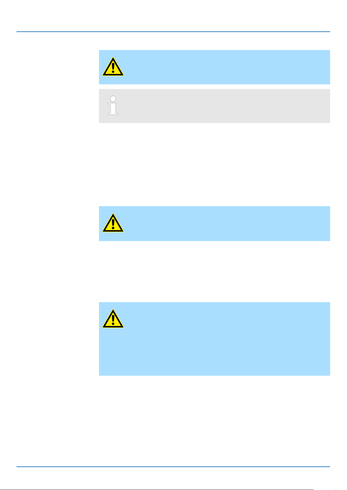
2.3
Dimensions
Dimensions CPU M13C
Basics and mounting
Dimensions
By means of up to 8 periphery modules, you can extend the internal I/O areas. The
attachment to the CPU is made by plugging them on the right side of the CPU.
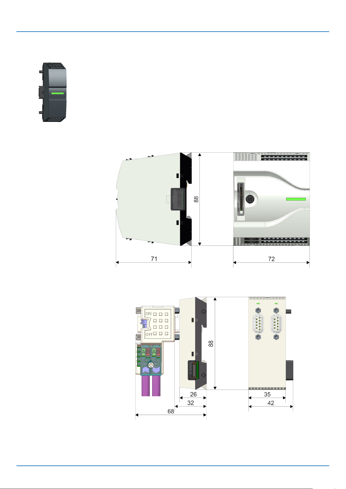
Dimensions extension
module EM M09
Dimensions in mm
Dimensions in mm
HB400 | CPU | M13-CCF0000 | en | 18-50 13
Page 14
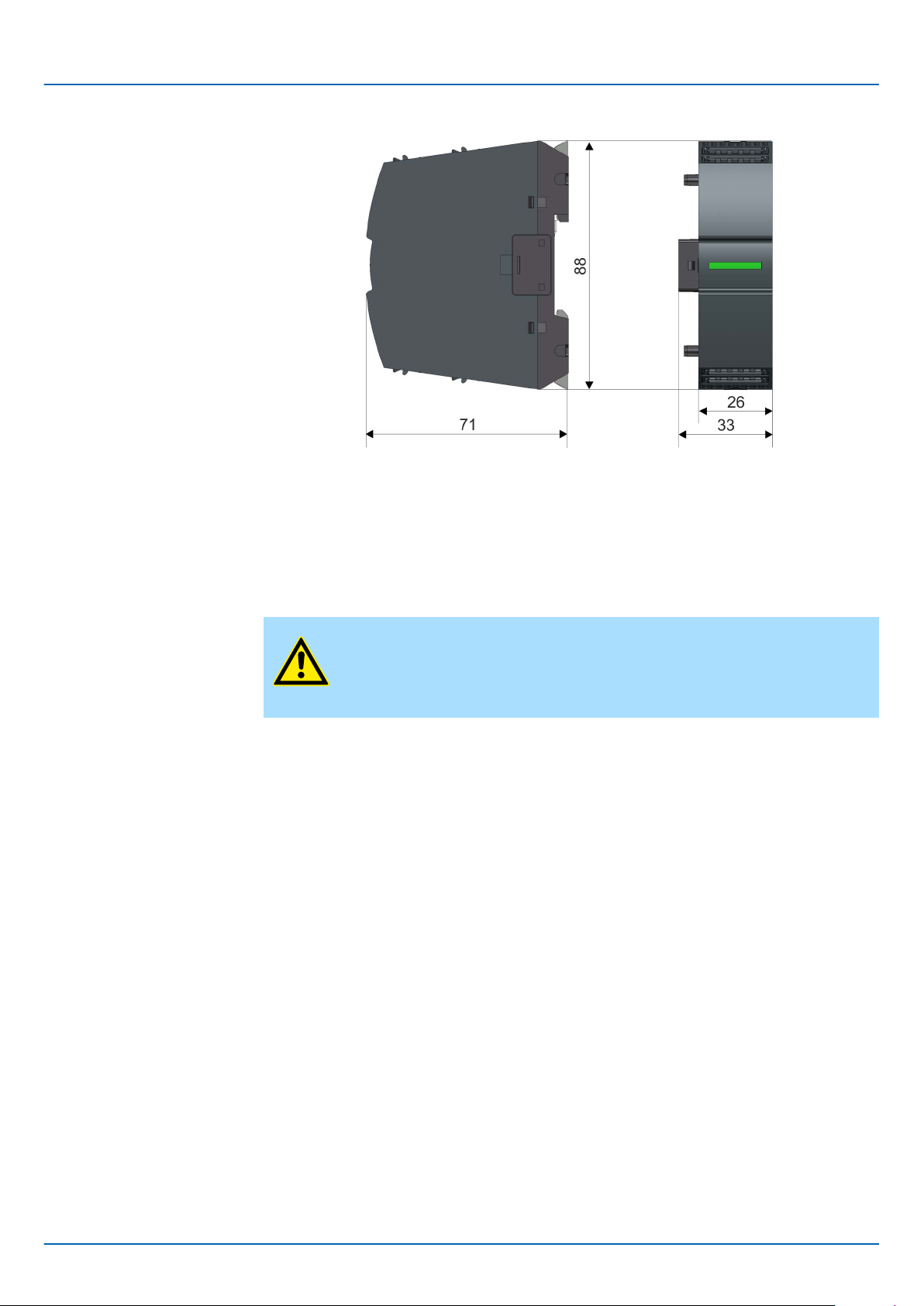
Basics and mounting
Mounting > Mounting CPU
Dimensions periphery
module
VIPA System MICRO
Dimensions in mm
2.4 Mounting
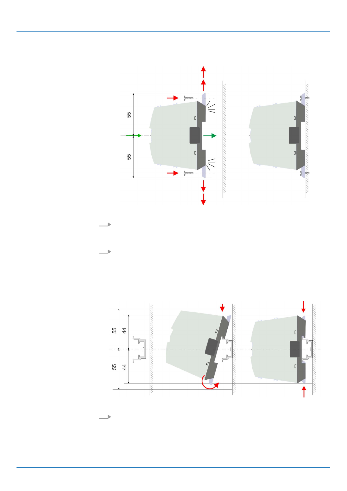
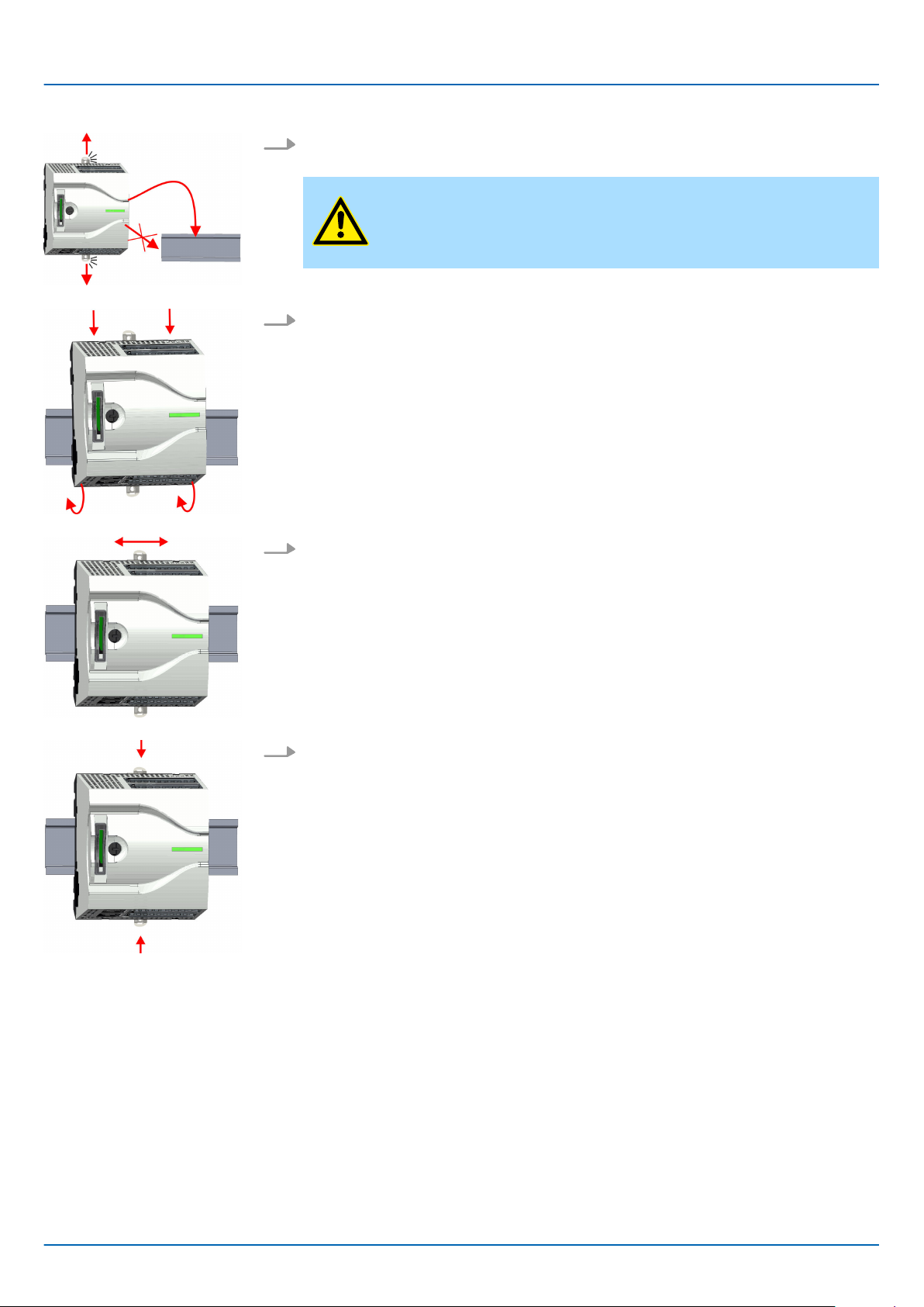
2.4.1
2.4.1.1 Mounting CPU without mounting rail
Mounting CPU
CAUTION!
Mounting without mounting rail is only permitted, if you only want to use
the CPU without extension and periphery modules. Otherwise, a
mounting rail must always be used for EMC technical reasons.
HB400 | CPU | M13-CCF0000 | en | 18-50 14
Page 15
VIPA System MICRO
Basics and mounting
Mounting > Mounting CPU
Proceeding
You can screw the CPU to the back wall by means of screws via the locking levers. This
happens with the following proceeding:
Dimensions in mm
1. The CPU has a locking lever on the upper and lower side. Pull these levers outwards as shown in the figure, until these engage 2x audible.
By this openings on the locking levers get visible.
ð
2.4.1.2
Proceeding
Mounting with mounting rail
2. Use the appropriate screws to fix your CPU to your back wall. Consider the installa-
tion clearances for the CPU.
The CPU is now mounted and can be wired.
ð
Dimensions in mm
1. Mount the mounting rail. Please consider that a clearance from the middle of the
mounting rail of at least 44mm respectively 55mm above and below exists.
HB400 | CPU | M13-CCF0000 | en | 18-50 15
Page 16
Basics and mounting
Mounting > Mounting CPU
VIPA System MICRO
2. The CPU has a locking lever on the upper and lower side. Pull these levers outwards as shown in the figure, until these engage audible.
CAUTION!
It is not allowed to mount the module sideways on the mounting rail,
as otherwise the module may be damaged.
3. Plug the CPU from the top onto the mounting rail and turn the CPU downward until
it rests on the mounting rail.
4. Move the CPU on the mounting rail at its position.
5. T
o fix the CPU at the mounting rail, move the locking levers back to the initial posi-
tion.
The CPU is now mounted and can be wired.
ð
HB400 | CPU | M13-CCF0000 | en | 18-50 16
Page 17
VIPA System MICRO
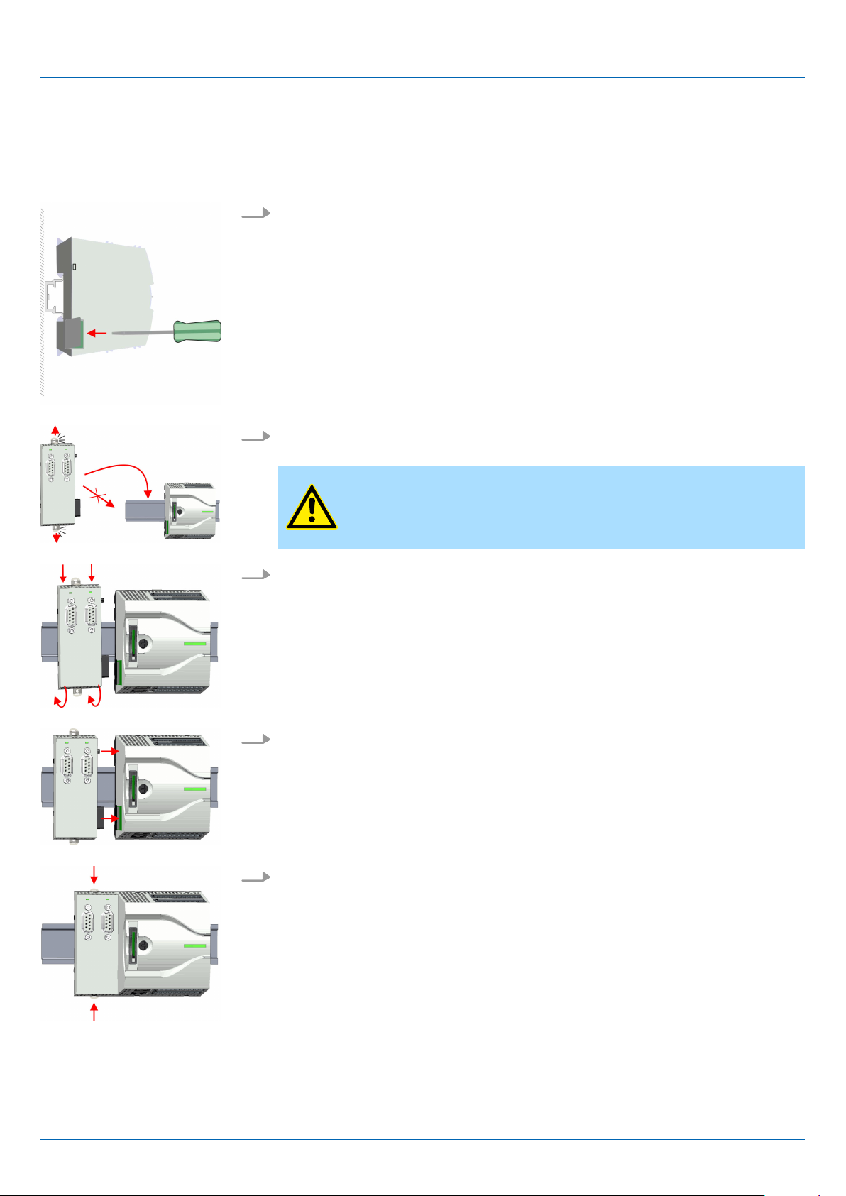
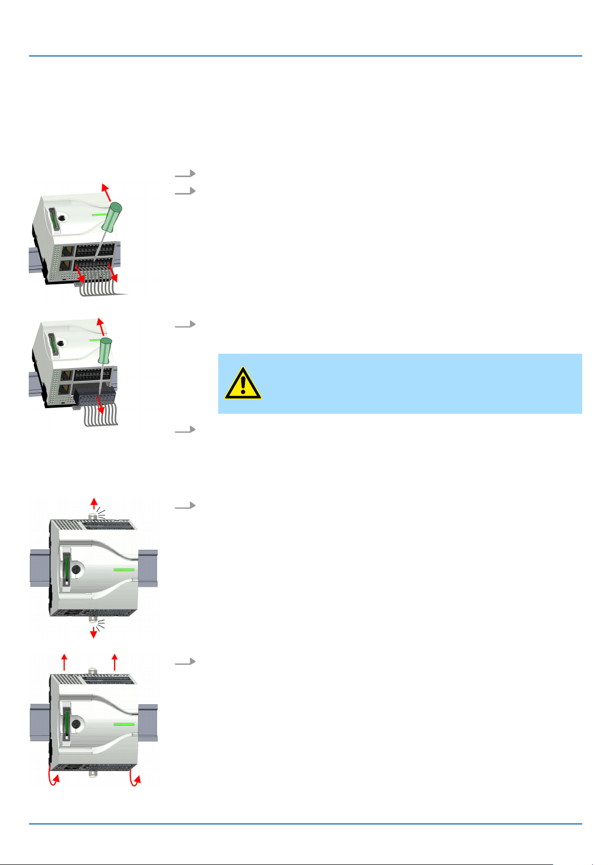
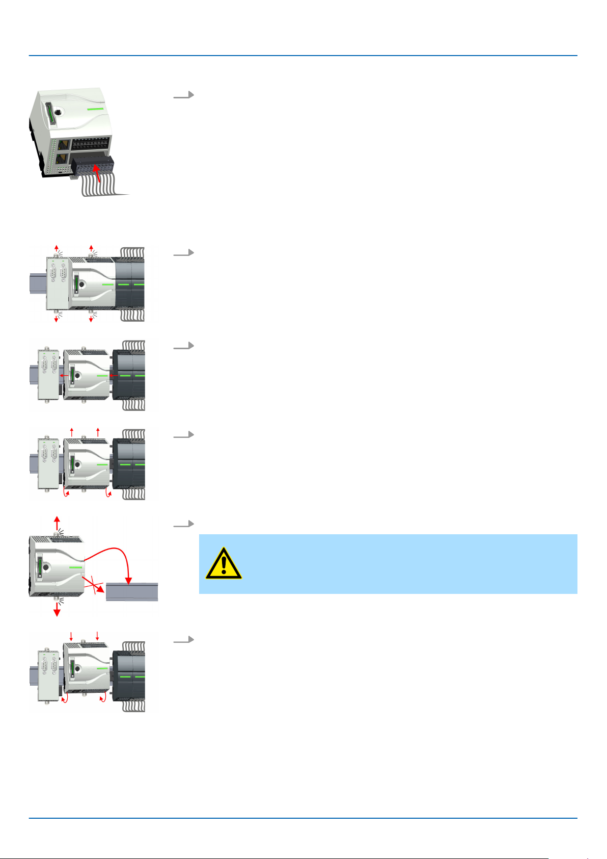
2.4.2 Mounting the extension module
Proceeding
ou have the possibility to extend the interfaces of the CPU by plugging an extension
Y
module. For this the extension module is plugged at the left side of the CPU. The mountings happens with the following proceeding:
1. Remove the bus cover with a screwdriver on the left side of the CPU.
2. The extension module has a locking lever on the upper and lower side. Pull these
levers outwards as shown in the figure, until these engage audible.
Basics and mounting
Mounting > Mounting the extension module
CAUTION!
It is not allowed to mount the module sideways on the mounting rail,
as otherwise the module may be damaged.
3. T
4. Attach the extension module to the CPU by sliding the extension module on the
5. To fix the extension module at the mounting rail, move the locking levers back to the
o mount plug the extension module from the top onto the mounting rail and turn
the extension module downward until it rests on the mounting rail.
mounting rail to the right until the interface connector slightly locks into the CPU.
initial position.
HB400 | CPU | M13-CCF0000 | en | 18-50 17
Page 18
Basics and mounting
Mounting > Mounting periphery module
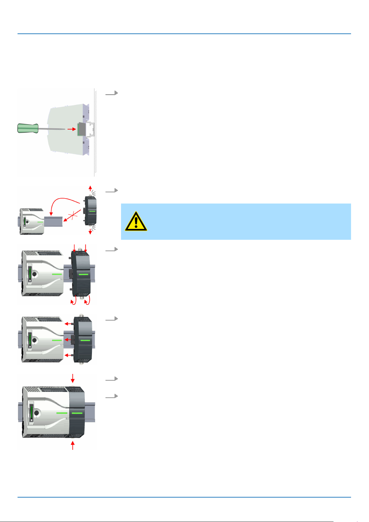
2.4.3 Mounting periphery module
Proceeding
ou have the possibility to extend the periphery area of the CPU by plugging up to 8
Y
periphery modules. For this the periphery modules are plugged at the right side of the
CPU. The mountings happens with the following proceeding:
1. Remove the bus cover with a screwdriver on the right side of the CPU.
2. Each periphery module has a locking lever on its upper and lower side. Pull these
levers outwards as shown in the figure, until these engage audible.
VIPA System MICRO
CAUTION!
It is not allowed to mount the module sideways on the mounting rail,
as otherwise the module may be damaged.
3. T
4. Attach the periphery module to the CPU by sliding the periphery module on the
5. T
6. Proceed in this way with additional periphery modules.
o mount plug the periphery module from the top onto the mounting rail and turn the
periphery module downward until it rests on the mounting rail.
mounting rail to the left until the interface connector slightly locks into the CPU.
o fix the periphery module at the mounting rail, move the locking levers back to the
initial position.
HB400 | CPU | M13-CCF0000 | en | 18-50 18
Page 19
VIPA System MICRO
2.5 Wiring
2.5.1 Wiring CPU
CPU connector
Basics and mounting
Wiring > Wiring CPU
CAUTION!
Consider temperature for external cables!
Cables may experience temperature increase due to system heat dissipation. Thus the cabling specification must be chosen 5°C above ambient
temperature!
CAUTION!
Separate insulation areas!
The system is specified for SEL
V/PELV environment. Devices, which are
attached to the system must meet theses specifications. Installation and
cable routing other than SELV/PELV specification must be separated
from the system’s equipment!
For wiring the CPU has removable connectors. With the wiring of the connectors a "pushin" spring-clip technique is used. This allows a quick and easy connection of your signal
and supply lines. The clamping of
f takes place by means of a screwdriver.
Data
Wiring procedure
Insert wire
U
max
I
max
Cross section
30V DC
10A
0.2 ... 1.5mm2 (A
WG 24 ... 16)
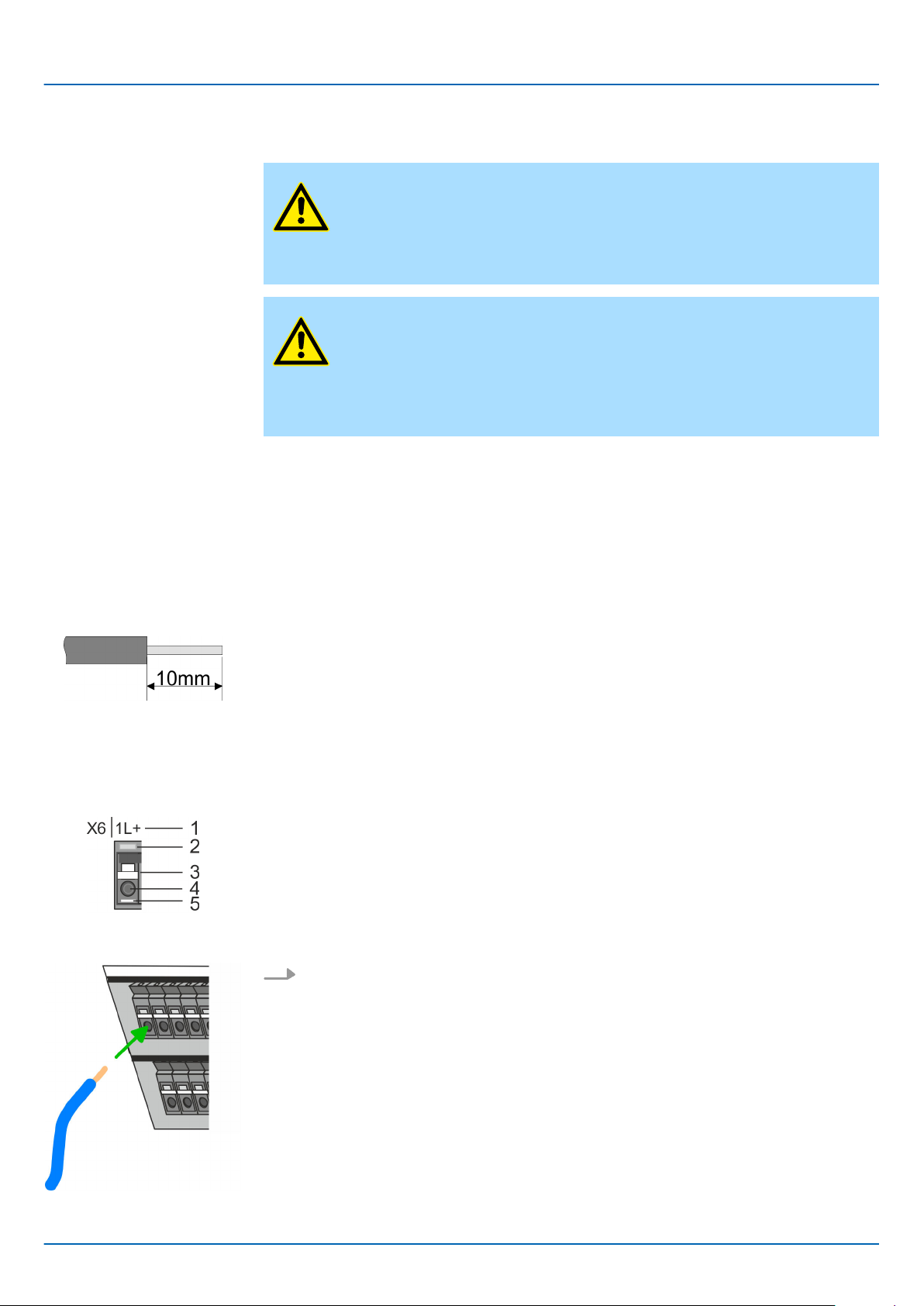
Stripping length 10mm
Use for wiring rigid wires respectively use wire sleeves. When using stranded wires you
have to press the release button with a screwdriver during the wiring.
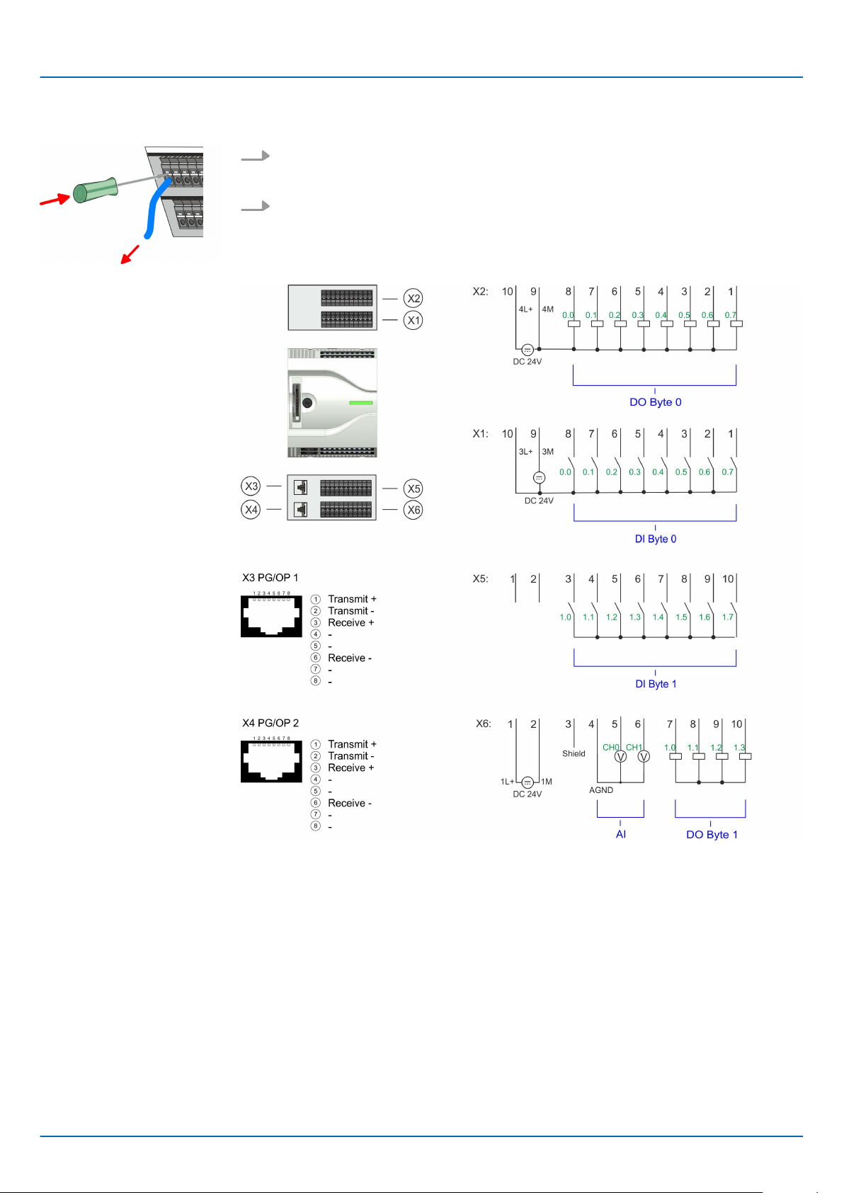
1 Labeling on the casing
2 Status LED
3 Release area
4 Connection hole for wire
5 Pin 1 of the connector is labelled by a white line
The wiring happens without a tool.
Determine according to the casing labelling the connection position and insert
through the round connection hole of the according contact your prepared wire until
it stops, so that it is fixed.
By pushing the contact spring opens, thus ensuring the necessary contact pres-
ð
sure.
HB400 | CPU | M13-CCF0000 | en | 18-50 19
Page 20
Basics and mounting
Wiring > Wiring CPU
VIPA System MICRO
Remove wire
Standard wiring
The wire is to be removed by means of a screwdriver with 2.5mm blade width.
1. Press with your screwdriver vertically at the release button.
The contact spring releases the wire.
ð
2. Pull the wire from the round hole.
HB400 | CPU | M13-CCF0000 | en | 18-50 20
Page 21
VIPA System MICRO
Basics and mounting
Wiring > Wiring CPU
Fusing
Remove connector
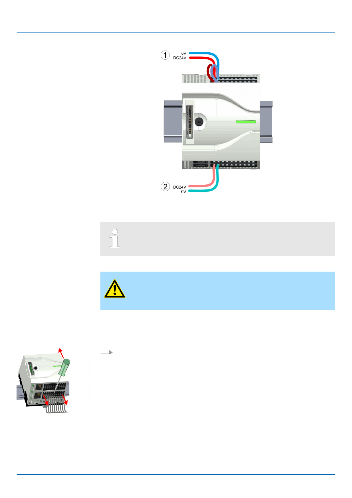
(1) X2: 4L+: DC 24V power section supply for integrated outputs
X1: 3L+: DC 24V power section supply for integrated inputs
(2) X6: 1L+ DC 24V for electronic power supply
The electronic power section supply is internally protected against higher
voltage by fuse. The fuse is located inside the CPU and can not be
changed by the user
CAUTION!
– The power section supply of the internal DOs is to be externally pro-
tected with a 8A fuse (fast) respectively by a line circuit breaker 8A
characteristics Z.
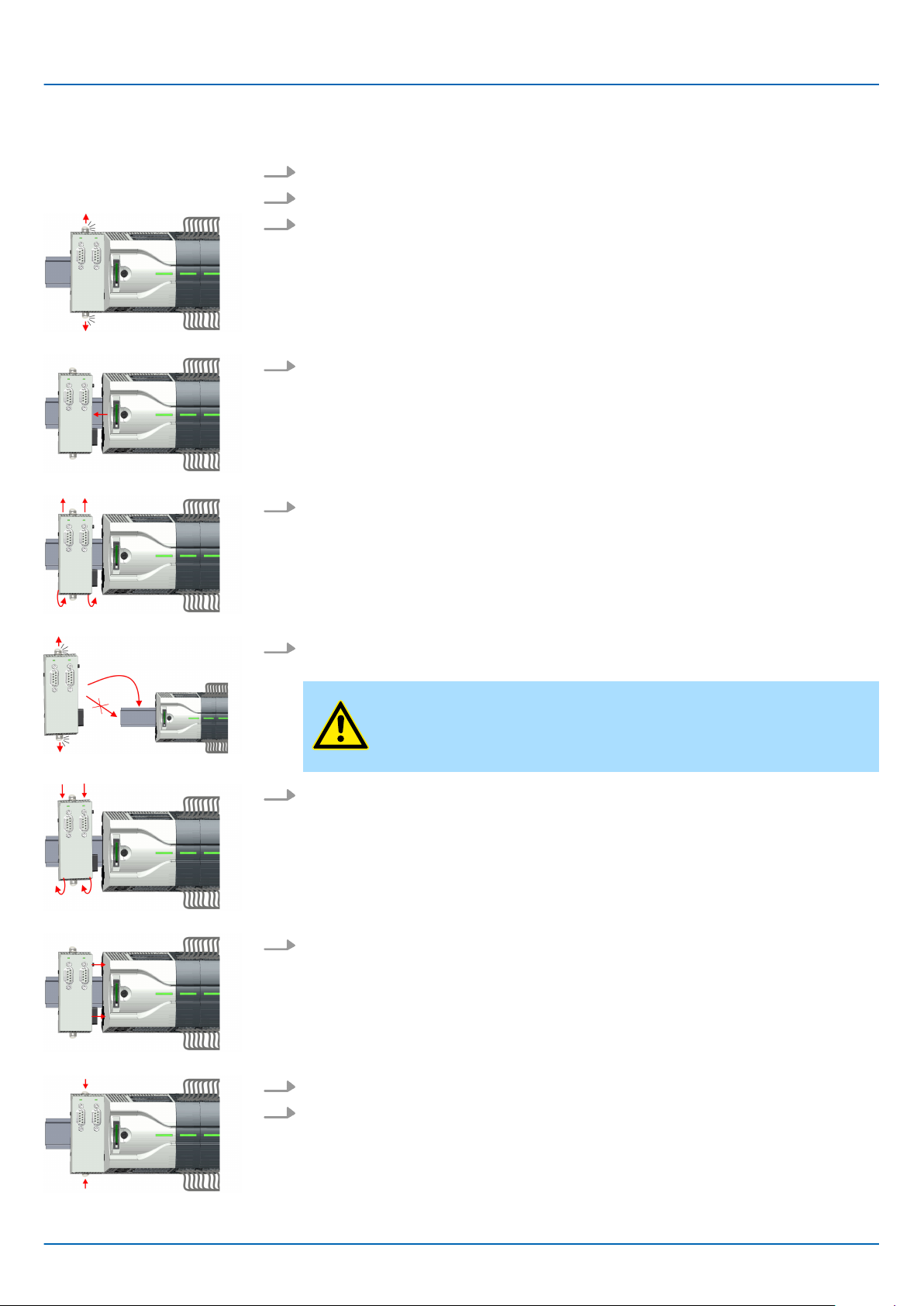
By means of a screwdriver there is the possibility to remove the connectors e.g. for
module exchange with a fix wiring. For this each connector has indentations for unlocking
at the top. Unlocking takes place by the following proceeding:
1. Remove connector:
Insert your screwdriver from above into one of the indentations.
.
HB400 | CPU | M13-CCF0000 | en | 18-50 21
Page 22

Basics and mounting
Wiring > Wiring CPU
2. Push the screwdriver backwards:
The connector is unlocked and can be removed.
ð
CAUTION!
ia wrong operation such as pressing the screwdriver down-
V
ward, the release lever may be damaged.
3. Plug connector:
The connector is plugged by plugging it directly into the release lever
VIPA System MICRO
.
HB400 | CPU | M13-CCF0000 | en | 18-50 22
Page 23

VIPA System MICRO
2.5.2 Wiring periphery module
Periphery module connector
Data
Wiring procedure
For wiring the periphery module has removable connectors. With the wiring of the connectors a "push-in" spring-clip technique is used. This allows a quick and easy connection
of your signal and supply lines. The clamping of
U
max
I
max
Cross section
Stripping length 10mm
Use for wiring rigid wires respectively use wire sleeves. When using stranded wires you
have to press the release button with a screwdriver during the wiring.
1 Labeling on the casing
2 Status LED
3 Release area
4 Connection hole for wire
5 Pin 1 of the connector is labelled by a white line
240V AC / 30V DC
10A
0.2 ... 1.5mm2 (A
WG 24 ... 16)
Basics and mounting
Wiring > Wiring periphery module
f takes place by means of a screwdriver.
Insert wire
Remove wire
The wiring happens without a tool.
Determine according to the casing labelling the connection position and insert
through the round connection hole of the according contact your prepared wire until
it stops, so that it is fixed.
By pushing the contact spring opens, thus ensuring the necessary contact pres-
ð
sure.
The wire is to be removed by means of a screwdriver with 2.5mm blade width.
1. Press with your screwdriver vertically at the release button.
The contact spring releases the wire.
ð
2. Pull the wire from the round hole.
Fusing
CAUTION!
– The power section supply of the output modules DO16 is to be exter-
nally protected with a 10A fuse (fast) respectively by a line circuit
breaker 10A characteristics Z.
The power section supply of the output part of the DIO8 is to be
–
externally protected with a 5A fuse (fast) respectively by a line circuit
breaker 5A characteristics Z.
HB400 | CPU | M13-CCF0000 | en | 18-50 23
Page 24

Basics and mounting
Wiring > Wiring periphery module
VIPA System MICRO
Remove connector
By means of a screwdriver there is the possibility to remove the connectors e.g. for
module exchange with a fix wiring. For this each connector has indentations for unlocking
at the top. Unlocking takes place by the following proceeding:
1. Remove connector:
Insert your screwdriver from above into one of the indentations.
2. Push the screwdriver backwards:
The connector is unlocked and can be removed.
ð
CAUTION!
V
ia wrong operation such as pressing the screwdriver down-
ward, the release lever may be damaged.
3. Plug connector:
The connector is plugged by plugging it directly into the release lever
.
HB400 | CPU | M13-CCF0000 | en | 18-50 24
Page 25
VIPA System MICRO
2.6 Demounting
Basics and mounting
Demounting > Demounting CPU
2.6.1
Remove connector
Demounting CPU
By means of a screwdriver there is the possibility to remove the connectors e.g. for
module exchange with a fix wiring. For this each connector has indentations for unlocking
at the top. Unlocking takes place by the following proceeding:
1. Power-of
2. Remove connector:
Insert your screwdriver from above into one of the indentations.
3. Push the screwdriver backwards:
ð
f your system.
The connector is unlocked and can be removed.
CAUTION!
Via wrong operation such as pressing the screwdriver downward, the connector may be damaged!
CPU replacement (standalone)
4. In this way
If more modules are connected to the CPU
page 27. If no other modules are connected to the CPU, the CPU is replaced according
to the following proceeding:
1. Use a screwdriver to pull the locking levers of the CPU outwards until these engage
audible.
2. Remove the CPU with a rotation upwards from the mounting rail.
, remove all plugged connectors on the CPU.
Ä
‘Option: CPU replacement in a system’
HB400 | CPU | M13-CCF0000 | en | 18-50 25
Page 26
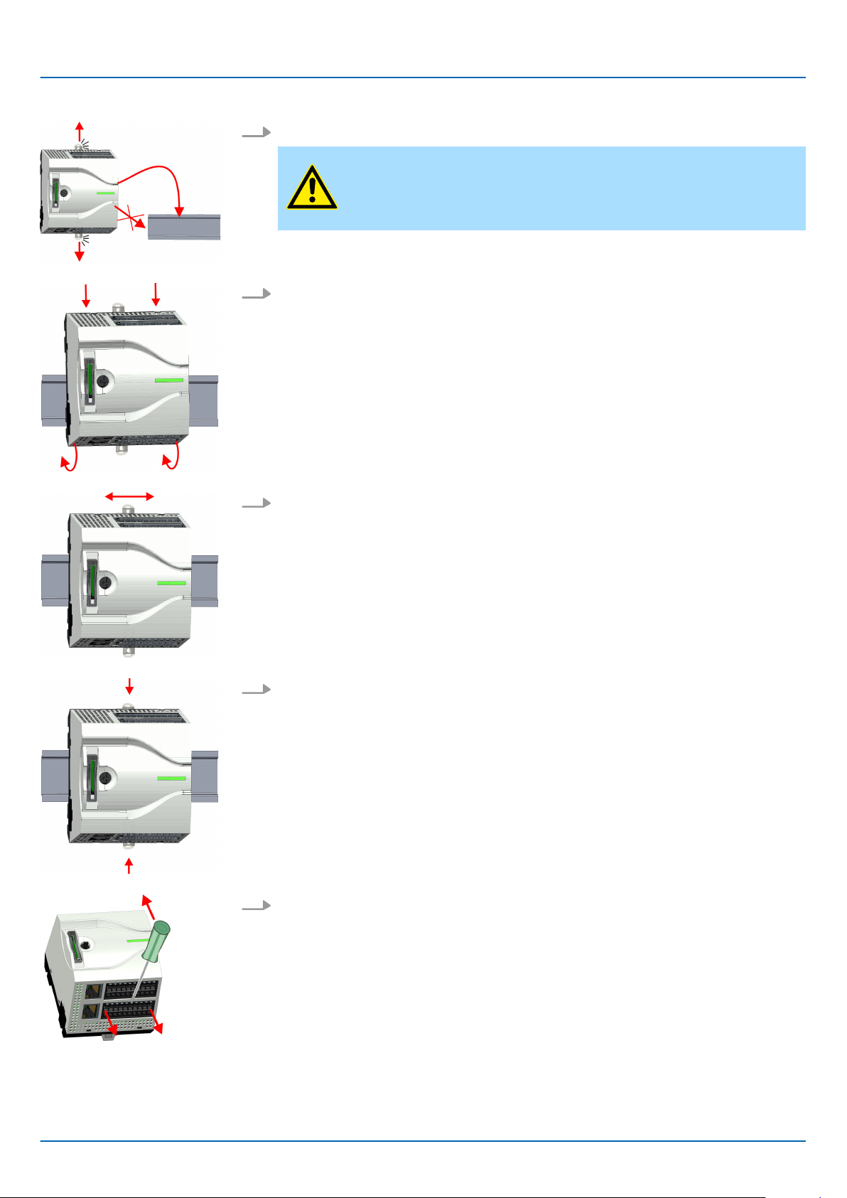
Basics and mounting
Demounting > Demounting CPU
VIPA System MICRO
3. Pull the locking levers of the CPU outwards until these engage audible.
CAUTION!
It is not allowed to mount the module sideways on the mounting rail,
as otherwise the module may be damaged!
4. Plug the CPU from the top onto the mounting rail and turn the CPU downward until
it rests on the mounting rail.
5. Move the CPU on the mounting rail at its position.
6. T
7. Remove the connectors, which are not necessary at the CPU.
o fix the CPU at the mounting rail, move the locking levers back to the initial posi-
tion.
HB400 | CPU | M13-CCF0000 | en | 18-50 26
Page 27
VIPA System MICRO
8. Plug again the wired connectors.
Now you can bring your system back into operation.
ð
Basics and mounting
Demounting > Demounting CPU
Option: CPU replacement
in a system
In the following the replacement of a CPU in a system is shown:
1. If there is an extension module connected to the CPU, you have to remove it from
the CPU. For this use a screwdriver to pull the locking levers of the extension
module and CPU outwards until these engage audible.
2. Disconnect all the modules, which are connected to the CPU by moving the CPU
along with the extension module on the mounting rail.
3. Remove the CPU with a rotation upwards from the mounting rail.
4. Pull the locking levers of the CPU outwards until these engage audible.
CAUTION!
It is not allowed to mount the module sideways on the mounting rail,
as otherwise the module may be damaged!
5. For mounting pull the locking levers of the CPU outwards until these engage
audible. Plug the CPU from the top onto the mounting rail and turn the CPU downward until it rests on the mounting rail.
HB400 | CPU | M13-CCF0000 | en | 18-50 27
Page 28
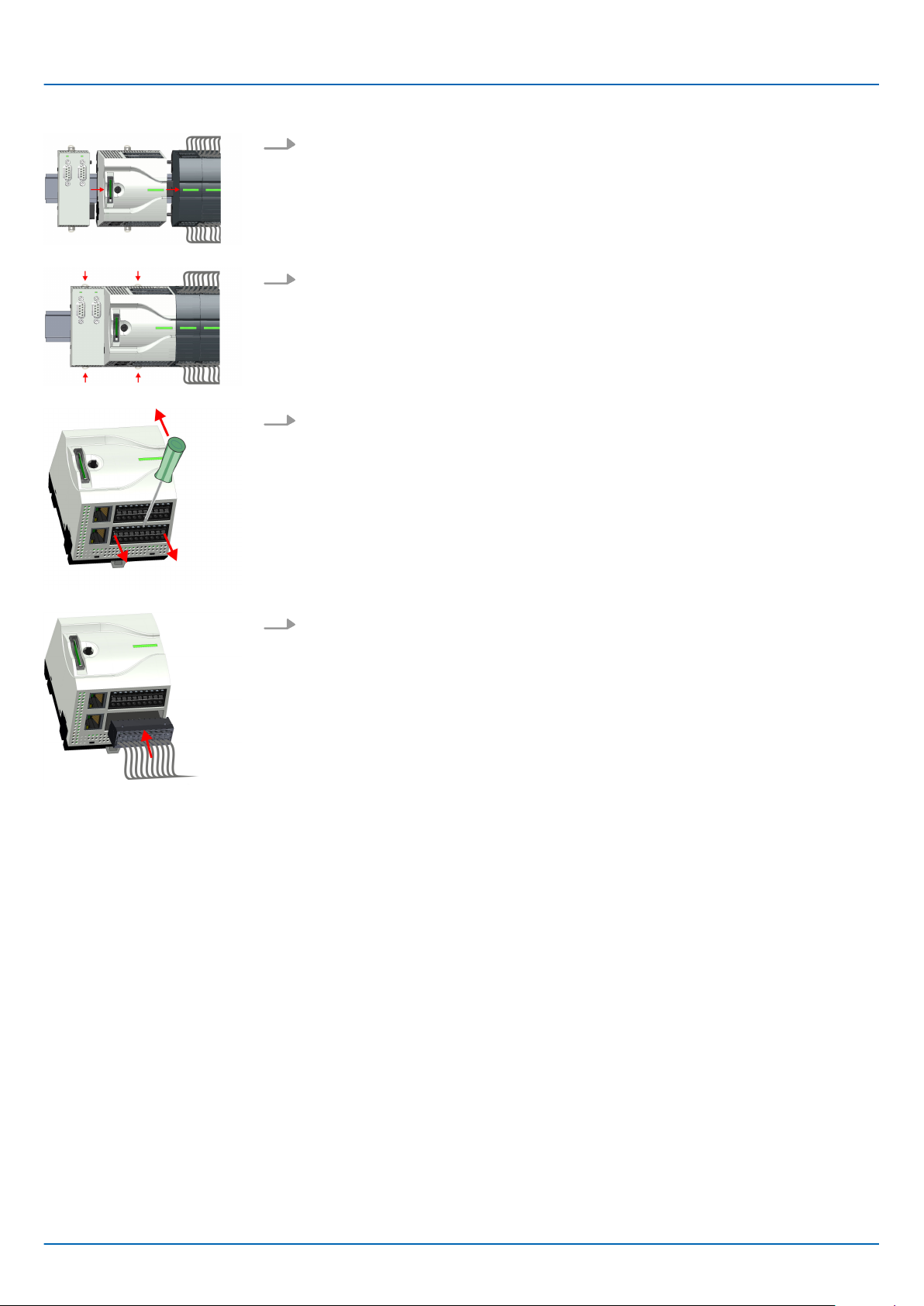
Basics and mounting
Demounting > Demounting CPU
VIPA System MICRO
6. Rebind your modules by moving the CPU along with the extension module on the
mounting rail.
7. T
8. Remove the connectors, which are not necessary at the CPU.
9. Plug again the wired connectors.
o fix the CPU at the mounting rail, move the locking levers back to the initial posi-
tion.
Now you can bring your system back into operation.
ð
HB400 | CPU | M13-CCF0000 | en | 18-50 28
Page 29
VIPA System MICRO
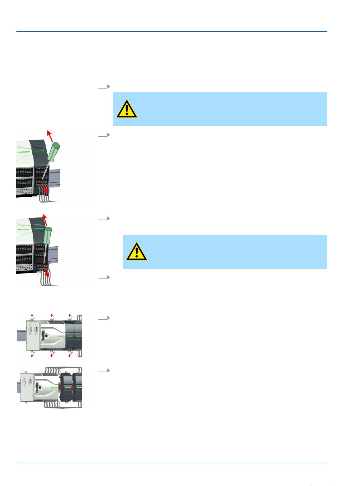
2.6.2 Demounting the extension module
Proceeding
1. Power-of
2. Remove the corresponding bus connectors.
3. Use a screwdriver to pull the locking levers of the extension module outwards until
these engage audible.
4. Remove the extension module from the CPU by sliding it on the mounting rail.
5. Remove the extension module with a rotation upwards from the mounting rail.
f your system.
Basics and mounting
Demounting > Demounting the extension module
6. Pull the locking levers of the extension module outwards until these engage
audible.
CAUTION!
It is not allowed to mount the module sideways on the mounting rail,
as otherwise the module may be damaged!
7. Plug the extension module from the top onto the mounting rail and turn the extension module downward until it rests on the mounting rail.
8. Reattach the extension module to the CPU by sliding the extension module on the
mounting rail to the right until the interface connector slightly locks into the CPU.
9. Move the locking levers back to the initial position.
10. Plug the corresponding bus connectors.
Now you can bring your system back into operation.
ð
HB400 | CPU | M13-CCF0000 | en | 18-50 29
Page 30
Basics and mounting
Demounting > Demounting periphery module
2.6.3 Demounting periphery module
Remove connector
By means of a screwdriver there is the possibility to remove the connectors e.g. for
module exchange with a fix wiring. For this each connector has indentations for unlocking
at the top. Unlocking takes place by the following proceeding:
1. Power-of
2. Remove connector:
Insert your screwdriver from above into one of the indentations.
VIPA System MICRO
f your system.
CAUTION!
Make sure that the working contacts from the relay module are disconnected from the power supply!
Replace the periphery
module
3. Push the screwdriver backwards:
The connector is unlocked and can be removed.
ð
CAUTION!
ia wrong operation such as pressing the screwdriver down-
V
ward, the connector may be damaged!
4. In this way
1. Remove the modules that are connected to the module to be replaced by pulling
their release levers outwards until these engage audible ...
2. ... and move the modules accordingly
, remove all plugged connectors on the periphery module.
.
HB400 | CPU | M13-CCF0000 | en | 18-50 30
Page 31

VIPA System MICRO
Basics and mounting
Demounting > Demounting periphery module
3. Remove the periphery module with a rotation upwards from the mounting rail.
4. Pull the locking levers outwards until these engage audible.
CAUTION!
It is not allowed to mount the module sideways on the mounting rail,
as otherwise the module may be damaged!
5. Plug the periphery module from the top onto the mounting rail and turn the
periphery module downward until it rests on the mounting rail.
6. Reconnect all modules by pushing them together again on the mounting rail.
7. Move the locking levers back to the initial position.
8. Remove the connectors, which are not necessary
.
HB400 | CPU | M13-CCF0000 | en | 18-50 31
Page 32

Basics and mounting
Demounting > Demounting periphery module
9. Plug again the wired connectors.
ð
VIPA System MICRO
Now you can bring your system back into operation.
HB400 | CPU | M13-CCF0000 | en | 18-50 32
Page 33

VIPA System MICRO
2.7 Installation guidelines
Basics and mounting
Installation guidelines
General
What does EMC mean?
Possible interference
causes
The installation guidelines contain information about the interference free deployment of a
PLC system. There is the description of the ways, interference may occur in your PLC,
how you can make sure the electromagnetic compatibility (EMC), and how you manage
the isolation.
Electromagnetic compatibility (EMC) means the ability of an electrical device, to function
error free in an electromagnetic environment without being interfered respectively without
interfering the environment.
The components of VIP
and meets high demands on the EMC. Nevertheless you should project an EMC planning
before installing the components and take conceivable interference causes into account.
Electromagnetic interferences may interfere your control via different ways:
n Electromagnetic fields (RF coupling)
n Magnetic fields with power frequency
n Bus system
n Power supply
n Protected earth conductor
Depending on the spreading medium (lead bound or lead free) and the distance to the
interference cause, interferences to your control occur by means of dif
mechanisms.
There are:
A are developed for the deployment in industrial environments
ferent coupling
Basic rules for EMC
n galvanic coupling
n capacitive coupling
n inductive coupling
n radiant coupling
In the most times it is enough to take care of some elementary rules to guarantee the
EMC. Please regard the following basic rules when installing your PLC.
ake care of a correct area-wide grounding of the inactive metal parts when installing
n T
your components.
– Install a central connection between the ground and the protected earth conductor
system.
– Connect all inactive metal extensive and impedance-low.
– Please try not to use aluminium parts. Aluminium is easily oxidizing and is there-
fore less suitable for grounding.
n When cabling, take care of the correct line routing.
– Organize your cabling in line groups (high voltage, current supply, signal and data
lines).
– Always lay your high voltage lines and signal respectively data lines in separate
channels or bundles.
– Route the signal and data lines as near as possible beside ground areas (e.g.
suspension bars, metal rails, tin cabinet).
HB400 | CPU | M13-CCF0000 | en | 18-50 33
Page 34

Basics and mounting
Installation guidelines
VIPA System MICRO
n Proof the correct fixing of the lead isolation.
–
Data lines must be laid isolated.
– Analog lines must be laid isolated. When transmitting signals with small ampli-
tudes the one sided laying of the isolation may be favourable.
– Lay the line isolation extensively on an isolation/protected earth conductor rail
directly after the cabinet entry and fix the isolation with cable clamps.
– Make sure that the isolation/protected earth conductor rail is connected impe-
dance-low with the cabinet.
– Use metallic or metallised plug cases for isolated data lines.
n In special use cases you should appoint special EMC actions.
– Consider to wire all inductivities with erase links.
– Please consider luminescent lamps can influence signal lines.
n Create a homogeneous reference potential and ground all electrical operating sup-
plies when possible.
– Please take care for the targeted employment of the grounding actions. The
grounding of the PLC serves for protection and functionality activity.
– Connect installation parts and cabinets with your PLC in star topology with the
isolation/protected earth conductor system. So you avoid ground loops.
– If there are potential differences between installation parts and cabinets, lay suffi-
ciently dimensioned potential compensation lines.
Isolation of conductors
Electrical, magnetically and electromagnetic interference fields are weakened by means
of an isolation, one talks of absorption. Via the isolation rail, that is connected conductive
with the rack, interference currents are shunt via cable isolation to the ground. Here you
have to make sure, that the connection to the protected earth conductor is impedancelow, because otherwise the interference currents may appear as interference cause.
When isolating cables you have to regard the following:
n If possible, use only cables with isolation tangle.
n The hiding power of the isolation should be higher than 80%.
n Normally you should always lay the isolation of cables on both sides. Only by means
of the both-sided connection of the isolation you achieve high quality interference
suppression in the higher frequency area. Only as exception you may also lay the isolation one-sided. Then you only achieve the absorption of the lower frequencies. A
one-sided isolation connection may be convenient, if:
the conduction of a potential compensating line is not possible.
–
– analog signals (some mV respectively µA) are transferred.
– foil isolations (static isolations) are used.
n With data lines always use metallic or metallised plugs for serial couplings. Fix the
isolation of the data line at the plug rack. Do not lay the isolation on the PIN 1 of the
plug bar!
n At stationary operation it is convenient to strip the insulated cable interruption free
and lay it on the isolation/protected earth conductor line.
n To fix the isolation tangles use cable clamps out of metal. The clamps must clasp the
isolation extensively and have well contact.
n Lay the isolation on an isolation rail directly after the entry of the cable in the cabinet.
Lead the isolation further on to your PLC and don't lay it on there again!
CAUTION!
Please regard at installation!
At potential dif
compensation current via the isolation connected at both sides.
Remedy: Potential compensation line
ferences between the grounding points, there may be a
HB400 | CPU | M13-CCF0000 | en | 18-50 34
Page 35

VIPA System MICRO
Basics and mounting
General data
2.8 General data
Conformity and approval
Conformity
CE 2014/35/EU Low-voltage directive
2014/30/EU EMC directive
Approval
UL - Refer to Technical data
others
RoHS 2011/65/EU Restriction of the use of certain hazardous substances in
electrical and electronic equipment
Protection of persons and device protection
Type of protection - IP20
Electrical isolation
to the field bus - electrically isolated
to the process level - electrically isolated
Insulation resistance - -
Insulation voltage to reference earth
Inputs / outputs - AC / DC 50V, test voltage AC 500V
Protective measures - against short circuit
Environmental conditions to EN 61131-2
Climatic
Storage / transport EN 60068-2-14 -25…+70°C
Operation
Horizontal installation hanging EN 61131-2 0…+60°C
Horizontal installation lying EN 61131-2 0…+60°C
Vertical installation EN 61131-2 0…+60°C
Air humidity EN 60068-2-30 RH1 (without condensation, rel. humidity 10…95%)
Pollution EN 61131-2 Degree of pollution 2
Installation altitude max. - 2000m
Mechanical
Oscillation EN 60068-2-6 1g, 9Hz ... 150Hz
Shock EN 60068-2-27 15g, 11ms
HB400 | CPU | M13-CCF0000 | en | 18-50 35
Page 36

Basics and mounting
General data
Mounting conditions
Mounting place - In the control cabinet
Mounting position - Horizontal and vertical
EMC Standard Comment
Emitted interference EN 61000-6-4 Class A (Industrial area)
VIPA System MICRO
Noise immunity
zone B
EN 61000-6-2 Industrial area
EN 61000-4-2
ESD
8kV at air discharge (degree of severity 3),
4kV at contact discharge (degree of severity 2)
EN 61000-4-3 HF field immunity (casing)
80MHz … 1000MHz, 10V/m, 80% AM (1kHz)
1.4GHz ... 2.0GHz, 3V/m, 80% AM (1kHz)
2GHz ... 2.7GHz, 1V/m, 80% AM (1kHz)
EN 61000-4-6 HF conducted
150kHz … 80MHz, 10V
, 80% AM (1kHz)
EN 61000-4-4 Burst, degree of severity 3
EN 61000-4-5 Surge, degree of severity 3 *
*) Due to the high-energetic single pulses with Surge an appropriate external protective circuit with lightning protection elements like conductors for lightning and overvoltage is
necessary
.
HB400 | CPU | M13-CCF0000 | en | 18-50 36
Page 37

VIPA System MICRO
3 Hardware description
3.1 Properties
Hardware description
Properties
M13-CCF0000
n SPEED7 technology integrated
n Programmable via VIP
TIA Portal
n 64kbyte work memory integrated (32kbyte code, 32kbyte data)
n Work memory expandable up to max. 128kbyte (64kbyte code, 64kbyte data)
n 128kbyte load memory integrated
n Slot for external storage media (lockable)
n Status LEDs for operating state and diagnostics
n X1/X5: DI 16xDC24V with status indication integrated
n X2/X6: DO 12xDC24V 0.5A with status indication integrated
n X3/X4: Ethernet PG/OP channel for active and passive Communication integrated
n X6: AI 2x12Bit (single ended) integrated
n Technological functions: 4 channels for counter, frequency measurement and
2 channels for pulse width modulation
n Pulse Train via SFB 49 (PULSE)
n PROFINET IO controller and I-Device via Ethernet PG/OP channel
n WebVisu project via Ethernet PG/OP channel
n Option: Extension module 2xRS485
n Option: max. 8 periphery modules
n I/O address area digital/analog 2048byte
n 512 timer/counter, 8192 flag byte
A SPEED7 Studio, Siemens SIMATIC Manager or Siemens
Ordering data
Type Order number Description
CPU M13C M13-CCF0000 System MICRO CPU M13C with options to extend work memory,
DI 16xDC24V
technological functions
EM M09 M09-0CB00 System MICRO extension: Serial interface 2x
(RS485/RS422, MPI, option PROFIBUS DP slave)
HB400 | CPU | M13-CCF0000 | en | 18-50 37
, DO 12xDC24 0.5A, AI 2x12bit and 4 channels
Page 38

Hardware description
Structure > System MICRO CPU M13C
3.2 Structure
VIPA System MICRO
3.2.1
CPU M13-CCF0000
System MICRO CPU M13C
1 Slot for external storage media (lockable)
2 Operating mode switch CPU
3 X3: Ethernet PG/OP channel
4 X4: Ethernet PG/OP channel
5 X2: Connector DO +0.0 ... DO +0.7
6 X1: Connector DI +0.0 ... DI +0.7
7 Status bar CPU
8 X5: Connector DI +1.0 ... DI +1.7
9 X6: Connector electronic section supply, AI, DO +1.0 ... DO +1.3
10 X2 4L+: LED DC 24V power section supply for on-board DO
11 X2 4M: LED on error, overload respectively short circuit at the outputs
12 X2 DO +0.x: LEDs DO +0.0 ... DO +0.7
13 X1 3L+: LED DC 24V power section supply for on-board DI
14 X1 DI +0.x: LEDs DI +0.0 ... DI +0.7
15 X5 DI +1.x: LEDs DI +1.0 ... DI +1.7
16 X6 1L+: LED DC 24V for electronic section supply
17 X6 DO +1.x: LEDs DO +1.0 ... DO +1.3
18 X3 Ethernet PG/OP channel: LEDs Link/Activity
19 X4 Ethernet PG/OP channel: LEDs Link/Activity
HB400 | CPU | M13-CCF0000 | en | 18-50 38
Page 39

VIPA System MICRO
3.2.2 Interfaces
Hardware description
Structure > Interfaces
HB400 | CPU | M13-CCF0000 | en | 18-50 39
Page 40

Hardware description
Structure > Interfaces
X1: DI byte 0
VIPA System MICRO
X1 Function Type LED
green
1 DI 0.7 I Digital input DI 7 / Counter 2 (B) / Frequency 2 *
2 DI 0.6 I Digital input DI 6 / Counter 2 (A) *
3 DI 0.5 I Digital input DI 5
4 DI 0.4 I
5 DI 0.3 I Digital input DI 3 / Counter 1 (A) *
6 DI 0.2 I Digital input DI 2
7 DI 0.1 I
8 DI 0.0 I Digital input DI 0 / Counter 0 (A) *
9 0 V I
10 DC 24V I 3L+: DC 24V for onboard DI power section supply
*) Max. input frequency 100kHz otherwise 1kHz.
Description
Digital input DI 4 / Counter 1 (B) / Frequency 1 *
Digital input DI 1 / Counter 0 (B) / Frequency 0 *
3M: GND for onboard DI power section supply
X2: DO byte 0
HB400 | CPU | M13-CCF0000 | en | 18-50 40
Page 41

VIPA System MICRO
Hardware description
Structure > Interfaces
X2 Function Type LED
green
1 DO 0.7 O Digital output DO 7
2 DO 0.6 O
3 DO 0.5 O Digital output DO 5
4 DO 0.4 O Digital output DO 4
5 DO 0.3 O Digital output DO 3 / Output channel counter 3
6 DO 0.2 O
7 DO 0.1 O Digital output DO 1 / PWM 1 / Output channel counter 1
8 DO 0.0 O Digital output DO 0 / PWM 0 / Output channel counter 0
9 0 V I
10 DC 24V I 4L+: DC 24V for onboard DO power section supply
X3/X4: Ethernet PG/OP
channel
8pin RJ45 jack:
n The RJ45 jack serves as interface to the Ethernet PG/OP channel.
red
Description
Digital output DO 6
Digital output DO 2 / Output channel counter 2
4M: GND for onboard DO power section supply / GND PWM
LED (red) is on at short circuit respectively overload
n This interface allows you to program respectively remote control your CPU and to
access the internal web server
.
n The Ethernet PG/OP channel (X3/X4) is designed as switch. This enables PG/OP
communication via the connections X3 and X4.
n Configurable connections are possible.
n DHCP respectively the assignment of the network configuration with a DHCP server
is supported.
n Default diagnostics addresses: 2025 ... 2040
n At the first commissioning respectively after a factory reset the Ethernet PG/OP
channel has no IP address. For online access to the CPU via the Ethernet PG/OP
channel, valid IP address parameters have to be assigned to this by means of your
configuration tool. This is called "initialization".
n Via the Ethernet PG/OP channel, you have access to:
– Device web page, where you can find information on firmware status, connected
peripherals, current cycle times, etc.
– WebVisu project, which is to be created in the SPEED7 Studio.
– PROFINET IO controller or the PROFINET I-Device.
Ä
Chap. 4.6 ‘Hardware configuration - Ethernet PG/OP channel’ page 71
X5: DI byte 1
HB400 | CPU | M13-CCF0000 | en | 18-50 41
Page 42

Hardware description
Structure > Interfaces
VIPA System MICRO
X5 Function Type LED
green
1 - -
2 - -
3 DI 1.0 I
4 DI 1.1 I Digital input DI 9 / Counter 3 (A) *
5 DI 1.2 I Digital input DI 10 / Counter 3 (B) / Frequency 3 *
6 DI 1.3 I
7 DI 1.4 I Digital input DI 12
8 DI 1.5 I Digital input DI 13
9 DI 1.6 I
10 DI 1.7 I Digital input DI 15 / Latch 3 *
*) Max. input frequency 100kHz otherwise 1kHz.
Description
reserved
reserved
Digital input DI 8
Digital input DI 11 / Gate 3 *
Digital input DI 14
X6: DC 24V, AI, DO byte 1
X6 Function Type LED
green
1 1L+ I 1L+: DC 24V for electronic section supply
2 1M I
3
4 2M I
5 AI 0 I
6 AI 1 I
7 DO 1.0 O Digital output DO 8
8 DO 1.1 O Digital output DO 9
9 DO 1.2 O
10 DO 1.3 O Digital output DO 11
I
Description
1M: DC 0V for electronic section supply
Shield
2M: Ground for analog inputs
Analog input AI 0
Analog input AI 1
Digital output DO 10
HB400 | CPU | M13-CCF0000 | en | 18-50 42
Page 43

VIPA System MICRO
X6: Electronic power
supply
3.2.3 LEDs
Hardware description
Structure > LEDs
The CPU has an integrated power supply. The power supply has to be provided with DC
24V
. Via the power supply not only the internal electronic of the CPU is provided with
voltage, but also the electronic from the integrated IO components. The power supply is
protected against polarity inversion and over current.
1 Status bar CPU
2 X3 Ethernet PG/OP channel: LEDs Link/Activity
3 X4 Ethernet PG/OP channel: LEDs Link/Activity
4 X1 DI +0.x: LEDs DI +0.0 ... DI +0.7
5 X1 3L+: LED DC 24V power section supply for on-board DI
6 X2 DO +0.x: LEDs DO +0.0 ... DO +0.7
7 X2 4L+: LED DC 24V power section supply for on-board DO
8 X2 4M: LED on error, overload respectively short circuit at the outputs
9 X5 DI +1.x: LEDs DI +1.0 ... DI +1.7
10 X6 DO +1.x: LEDs DO +1.0 ... DO +1.3
11 X6 1L+: LED DC 24V for electronic section supply
Status bar CPU
Status bar Function
Ä
Ä
46
Ä
46
47
green
yellow
red
Ethernet PG/OP channel
X3/X4 Function
green
yellow
HB400 | CPU | M13-CCF0000 | en | 18-50 43
CPU - RUN: CPU is in state RUN without error.
Ä
CPU - STOP: CPU is in STOP state.
CPU - system fault: System error occurred.
Ethernet PG/OP channel X3/X4: Link/Activity
Ethernet PG/OP channel X3/X4: Speed
46
Ä
47
Page 44

Hardware description
Structure > LEDs
X1 DI +0.x
VIPA System MICRO
Digital input LED
green
DI +0.0 ... DI +0.7 Digital input I+0.0 ... 0.7 has "1" signal
Description
Digital input I+0.0 ... 0.7 has "0" signal
X1 3L+
Power supply LED
green
3L+ DC 24V power section supply inputs OK
Description
DC 24V power section supply inputs not available
X2 DO +0.x
Digital output LED
green
DO +0.0 ... DO +0.7 Digital output Q+0.0 ... 0.7 has "1" signal
Description
Digital output Q+0.0 ... 0.7 has "0" signal
X2 4L+
Power supply LED
green
4L+ DC 24V power section supply outputs OK
Description
DC 24V power section supply outputs not available
X2 4M
Error LED
red
4M Error, overload respectively short circuit on the outputs
Description
no error
X5 DI +1.x
Digital input LED
green
DI +1.0 ... DI +1.7 Digital input I+1.0 ... 1.7 has "1" signal
Description
Digital input I+1.0 ... 1.7 has "0" signal
HB400 | CPU | M13-CCF0000 | en | 18-50 44
Page 45

VIPA System MICRO
X6 DO +1.x
Hardware description
Structure > LEDs
Digital output LED
green
DO +1.0 ... DO +1.3 Digital output Q+1.0 ... 1.3 has "1" signal
Description
Digital output Q+1.0 ... 1.3 has "0" signal
X6 1L+
Power supply LED
green
1L+ DC 24V electronic section supply OK
Description
DC 24V electronic section supply not available
HB400 | CPU | M13-CCF0000 | en | 18-50 45
Page 46

Hardware description
Structure > LEDs
3.2.3.1 Status bar CPU
LED Description
Start-up
LED yellow blinks with 1Hz: State of the CPU after PowerON
LEDs green are blinking with 2Hz: During the start-up (OB 100) the status bar blinks for at least 3s.
Operation
LED yellow on: CPU is in STOP state.
LED red on: CPU is in error state.
LEDs green on: CPU is in RUN state without error.
LED red blinks with 1Hz and LED green is on: CPU is in RUN state with error/warning.
LED red on and LED green blinks with 1Hz: CPU is in STOP state, configured holding point reached.
LED red blinks with 1Hz and LED green blinks with 2Hz: Diagnostic messages detected during start-up.
LED red on and LED yellow on: CPU is in error state. There is a system error or an internal error has occurred.
Here a write access is made to the memory card. As long as the LEDs red and yellow are on, do not remove the
memory card.
VIPA System MICRO
Overall reset
Factory reset
Firmware update
LED yellow blinks with 2Hz: Hardware configuration is loaded.
LEDs green are blinking with 1Hz: Blinking test (started via configuration tool)
LED green on and LED green flickers: Access to the memory card in the RUN state.
LED red blinks with 1Hz and LED green flickers: Access to the memory card with CPU is in RUN state with error/
warning.
LED yellow flickers: Access to the memory card in STOP state.
LED yellow blinks with 1Hz: Overall reset is requested
LED yellow blinks with 2Hz: Overall reset is executed.
LED yellow on: Overall reset was successfully finished.
LED yellow blinks with 2Hz: Reset to factory setting is executed.
LED red blinks with 1Hz and LED yellow blinks with 1Hz: Reset to factory settings was finished without errors.
Please perform a power cycle!
LED red and LED yellow are alternately blinking with 1Hz: A new firmware is available on the memory card.
LED yellow blinks with 2Hz: A firmware update is in progress.
LED yellow flickers: Access the memory card during the firmware update.
LED red and LED yellow are blinking with 1Hz: Firmware update finished without error. Please perform a power
cycle!
LED red blinks with 1Hz: Error during Firmware update.
HB400 | CPU | M13-CCF0000 | en | 18-50 46
Page 47

VIPA System MICRO
3.2.3.2 LEDs Ethernet PG/OP channel
X3/X4: LEDs
Hardware description
Structure > Slot for storage media
L/A
Link/Activity
green
not relevant: X
S
Speed
yellow
X The Ethernet PG/OP channel is physically connected to the Ethernet
X There is no physical connection.
X Blinking: Shows Ethernet activity.
3.2.4 Memory management
General
The CPU has an integrated memory. Information about the capacity of the memory may
be found at the front of the CPU. The memory is divided into the following parts:
n Load memory 128kbyte
n Code memory (50% of the work memory)
n Data memory (50% of the work memory)
n W
Description
interface.
The Ethernet interface of the Ethernet PG/OP channel has a transfer
rate of 100Mbit.
The Ethernet interface of the Ethernet PG/OP channel has a transfer
rate of 10Mbit.
ork memory 64kbyte
– There is the possibility to extend the work memory to its maximum capacity
128kbyte by means of a VSC.
3.2.5 Slot for storage media
Overview
In this slot you can insert the following storage media:
n VSD - VIPA SD-Card
n VSC - VIPASetCard
– External memory card for programs and firmware.
– External memory card (VSD) for programs and firmware with the possibility to
unlock optional functions like work memory and field bus interfaces.
Ä
– These functions can be purchased separately.
media - VSD, VSC’ page 98
– To activate the corresponding card is to be installed and a Overall reset is to be
Ä
established.
To avoid malfunctions, you should use memory cards of VIPA. These correspond to the industrial standard. A list of the currently available VSD
respectively VSC can be found at www
Chap. 4.12 ‘Overall reset’ page 94
Chap. 4.15 ‘Deployment storage
.vipa.com
HB400 | CPU | M13-CCF0000 | en | 18-50 47
Page 48

Hardware description
Structure > Operating mode switch
3.2.6 Buffering mechanisms
The CPU has a capacitor-based mechanism to buf
failure for max. 30 days. With PowerOFF the content of the RAM is automatically stored
in the Flash (NVRAM).
3.2.7 Operating mode switch
General
VIPA System MICRO
fer the internal clock in case of power
CAUTION!
Please connect the CPU for approximately 1 hour to the power supply
that the internal buffering mechanism is loaded accordingly.
In case of failure of the buffer mechanism Date and Time 01.09.2009
Ä
00:00:00 set. Additionally, you receive a diagnostics message.
4.19 ‘Diagnostic entries’ page 105
Chap.
, so
n With the operating mode switch you may switch the CPU between ST
n During the transition from STOP to RUN the operating mode START-UP is driven by
the CPU.
n Placing the switch to MR (Memory Reset), you request an overall reset with following
load from memory card, if a project there exists.
OP and RUN.
HB400 | CPU | M13-CCF0000 | en | 18-50 48
Page 49

VIPA System MICRO
Option: Extension module EM M09 2x serial interface
3.3 Option: Extension module EM M09 2x serial interface
EM M09
Please note that the interface X2 MPI(PB) does not provide DC 24V,
which is necessary for some programming adapters!
Hardware description
X1 PtP (RS422/485)
9pin SubD jack (isolated):
Using the PtP functionality the RS485 interface is allowed to connect via serial point to
point connection to dif
n Protocols:
– ASCII
– STX/ETX
– 3964R
– USS
– Modbus master (ASCII, RTU)
n Serial bus connection
– Full-duplex Four-wire operation (RS422)
– Half-duplex Two-wire operation (RS485)
– Data transfer rate: max. 115 kBaud
Ä
Chap. 8 ‘Option: PtP communication’ page 202
ferent source res. target systems.
HB400 | CPU | M13-CCF0000 | en | 18-50 49
Page 50

Hardware description
Option: Extension module EM M09 2x serial interface
VIPA System MICRO
X2 MPI(PB)
LEDs
9pin SubD jack (isolated):
The interface supports the following functions, which are switch able:
n MPI (default / after overall reset)
The MPI interface serves for the connection between programming unit and CPU. By
means of this the project engineering and programming happens. In addition MPI
serves for communication between several CPUs or between HMIs and CPU.
Standard setting is MPI address 2.
n PROFIBUS DP slave (optional)
The PROFIBUS slave functionality of this interface can be activated by configuring
Ä
the sub module ‘MPI/DP’ of the CPU in the hardware configuration.
‘Option: Deployment PROFIBUS communication’ page 216
To switch the interface X2 MPI(PB) to PROFIBUS functionality you have
to activate the according bus functionality by means of a VSC storage
media from VIP
reset the according functionality is activated.
storage media - VSD, VSC’ page 98
X1 PtP
TxD
A. By plugging the VSC storage card and then an overall
Ä
Chap. 4.15 ‘Deployment
Description
Chap. 9
green flickers
X2 MPI(PB)
DE
green
green flashes
Send activity
No send activity
Description
n Power supply Expansion module EM M09 available
n Slave is in DE (data exchange)
n Slave exchanges data with the master
n Slave is in RUN state
n LED flashes at PowerON of EM M09
n No power supply EM M09 available
n Slave has no configuration
HB400 | CPU | M13-CCF0000 | en | 18-50 50
Page 51

VIPA System MICRO
3.4 Technical data
Hardware description
Technical data > Technical data CPU
3.4.1
Order no. M13-CCF0000
Type CPU M13C
Module ID -
Technical data power supply
Power supply (rated value) DC 24 V
Power supply (permitted range) DC 20.4...28.8 V
Reverse polarity protection
Current consumption (no-load operation) 120 mA
Current consumption (rated value) 360 mA
Inrush current 3 A
I²t 0.1 A²s
Max. current drain at backplane bus 1 A
Max. current drain load supply -
Power loss 7 W
Technical data digital inputs
Technical data CPU
ü
Number of inputs 16
Cable length, shielded 1000 m
Cable length, unshielded 600 m
Rated load voltage DC 24 V
Reverse polarity protection of rated load voltage
Current consumption from load voltage L+ (without load) 25 mA
Rated value DC 24 V
Input voltage for signal "0" DC 0...5 V
Input voltage for signal "1" DC 15...28.8 V
Input voltage hysteresis -
Signal logic input Sinking input
Frequency range -
Input resistance -
Input current for signal "1" 3 mA
Connection of Two-Wire-BEROs possible
Max. permissible BERO quiescent current 0.5 mA
ü
ü
Input delay of "0" to "1" 3 µs – 15 ms / 0.5 ms – 15 ms
Input delay of "1" to "0" 3 µs – 15 ms / 0.5 ms – 15 ms
Number of simultaneously utilizable inputs horizontal configuration
HB400 | CPU | M13-CCF0000 | en | 18-50 51
16
Page 52

Hardware description
Technical data > Technical data CPU
Order no. M13-CCF0000
VIPA System MICRO
Number of simultaneously utilizable inputs vertical configuration
Input characteristic curve IEC 61131-2, type 1
Initial data size 16 Bit
Technical data digital outputs
Number of outputs 12
Cable length, shielded 1000 m
Cable length, unshielded 600 m
Rated load voltage DC 24 V
Reverse polarity protection of rated load voltage
Current consumption from load voltage L+ (without load) 20 mA
Total current per group, horizontal configuration, 40°C 6 A
Total current per group, horizontal configuration, 60°C 6 A
Total current per group, vertical configuration 6 A
Output voltage signal "1" at min. current L+ (-0.8 V)
Output voltage signal "1" at max. current L+ (-0.8 V)
16
ü
Output current at signal "1", rated value 0.5 A
Signal logic output Sinking output
Output current, permitted range to 40°C 5 mA to 0.6 A
Output current, permitted range to 60°C 5 mA to 0.6 A
Output current at signal "0" max. (residual current) 0.5 mA
Output delay of "0" to "1" 2 µs / 30 µs
Output delay of "1" to "0" 3 µs / 175 µs
Minimum load current -
Lamp load 10 W
Parallel switching of outputs for redundant control of a load not possible
Parallel switching of outputs for increased power not possible
Actuation of digital input
Switching frequency with resistive load max. 1000 Hz
Switching frequency with inductive load max. 0.5 Hz
Switching frequency on lamp load max. 10 Hz
Internal limitation of inductive shut-off voltage L+ (-45 V)
ü
Short-circuit protection of output yes, electronic
Trigger level 1 A
Number of operating cycle of relay outputs -
Switching capacity of contacts -
HB400 | CPU | M13-CCF0000 | en | 18-50 52
Page 53

VIPA System MICRO
Order no. M13-CCF0000
Output data size 12 Bit
Technical data analog inputs
Number of inputs 2
Cable length, shielded 200 m
Rated load voltage -
Reverse polarity protection of rated load voltage -
Current consumption from load voltage L+ (without load) -
Hardware description
Technical data > Technical data CPU
Voltage inputs
Min. input resistance (voltage range) 100 kΩ
Input voltage ranges 0 V ... +10 V
Operational limit of voltage ranges +/-3.5%
Operational limit of voltage ranges with SFU -
Basic error limit voltage ranges +/-3.0%
Basic error limit voltage ranges with SFU -
Destruction limit voltage max. 30V
Current inputs -
Max. input resistance (current range) -
Input current ranges -
Operational limit of current ranges -
Operational limit of current ranges with SFU -
Basic error limit current ranges -
Radical error limit current ranges with SFU -
Destruction limit current inputs (electrical current) -
ü
Destruction limit current inputs (voltage) -
Resistance inputs -
Resistance ranges -
Operational limit of resistor ranges -
Operational limit of resistor ranges with SFU -
Basic error limit -
Basic error limit with SFU -
Destruction limit resistance inputs -
Resistance thermometer inputs -
Resistance thermometer ranges -
Operational limit of resistance thermometer ranges -
Operational limit of resistance thermometer ranges with
SFU
HB400 | CPU | M13-CCF0000 | en | 18-50 53
-
Page 54

Hardware description
Technical data > Technical data CPU
Order no. M13-CCF0000
Basic error limit thermoresistor ranges -
Basic error limit thermoresistor ranges with SFU -
Destruction limit resistance thermometer inputs -
Thermocouple inputs -
Thermocouple ranges -
Operational limit of thermocouple ranges -
Operational limit of thermocouple ranges with SFU -
Basic error limit thermoelement ranges -
Basic error limit thermoelement ranges with SFU -
Destruction limit thermocouple inputs -
Programmable temperature compensation -
External temperature compensation -
VIPA System MICRO
Internal temperature compensation -
Technical unit of temperature measurement -
Resolution in bit 12
Measurement principle successive approximation
Basic conversion time 2 ms
Noise suppression for frequency 40 dB
Initial data size 4 Byte
Technical data analog outputs
Number of outputs -
Cable length, shielded -
Rated load voltage -
Reverse polarity protection of rated load voltage -
Current consumption from load voltage L+ (without load) -
Voltage output short-circuit protection -
Voltage outputs -
Min. load resistance (voltage range) -
Max. capacitive load (current range) -
Max. inductive load (current range) -
Output voltage ranges -
Operational limit of voltage ranges -
Basic error limit voltage ranges with SFU -
Destruction limit against external applied voltage -
Current outputs -
Max. in load resistance (current range) -
HB400 | CPU | M13-CCF0000 | en | 18-50 54
Page 55

VIPA System MICRO
Order no. M13-CCF0000
Max. inductive load (current range) -
Typ. open circuit voltage current output -
Output current ranges -
Operational limit of current ranges -
Radical error limit current ranges with SFU -
Destruction limit against external applied voltage -
Settling time for ohmic load -
Settling time for capacitive load -
Settling time for inductive load -
Resolution in bit -
Conversion time -
Substitute value can be applied -
Hardware description
Technical data > Technical data CPU
Output data size -
Technical data counters
Number of counters 4
Counter width 32 Bit
Maximum input frequency 100 kHz
Maximum count frequency 400 kHz
Mode incremental encoder
Mode pulse / direction
Mode pulse
Mode frequency counter
Mode period measurement
Gate input available
Latch input available
Reset input available -
Counter output available
Load and working memory
ü
ü
ü
ü
ü
ü
ü
ü
Load memory, integrated 128 KB
Load memory, maximum 128 KB
Work memory, integrated 64 KB
Work memory, maximal 128 KB
Memory divided in 50% program / 50% data
Memory card slot SD/MMC-Card with max. 2 GB
Hardware configuration
Racks, max. 1
HB400 | CPU | M13-CCF0000 | en | 18-50 55
ü
Page 56

Hardware description
Technical data > Technical data CPU
Order no. M13-CCF0000
Modules per rack, max. 8
Number of integrated DP master -
Number of DP master via CP -
Operable function modules -
Operable communication modules PtP -
Operable communication modules LAN -
Status information, alarms, diagnostics
Status display yes
Interrupts yes, parameterizable
Process alarm yes, parameterizable
Diagnostic interrupt yes, parameterizable
Diagnostic functions yes, parameterizable
VIPA System MICRO
Diagnostics information read-out possible
Supply voltage display green LED
Group error display red LED
Channel error display red LED per group
Isolation
Between channels
Between channels of groups to 16
Between channels and backplane bus
Between channels and power supply -
Max. potential difference between circuits DC 75 V/ AC 50 V
Max. potential difference between inputs (Ucm) -
Max. potential difference between Mana and Mintern
(Uiso)
Max. potential difference between inputs and Mana (Ucm) -
Max. potential difference between inputs and Mintern
(Uiso)
Max. potential difference between Mintern and outputs -
ü
ü
-
-
Insulation tested with DC 500 V
Command processing times
Bit instructions, min. 0.02 µs
Word instruction, min. 0.02 µs
Double integer arithmetic, min. 0.02 µs
Floating-point arithmetic, min. 0.12 µs
Timers/Counters and their retentive characteristics
Number of S7 counters 512
HB400 | CPU | M13-CCF0000 | en | 18-50 56
Page 57

VIPA System MICRO
Order no. M13-CCF0000
S7 counter remanence adjustable 0 up to 256
S7 counter remanence adjustable C0 .. C7
Number of S7 times 512
S7 times remanence adjustable 0 up to 256
S7 times remanence adjustable not retentive
Data range and retentive characteristic
Number of flags 8192 Byte
Bit memories retentive characteristic adjustable adjustable 0 up to 256
Bit memories retentive characteristic preset MB0 .. MB15
Number of data blocks 1024
Max. data blocks size 64 KB
Max. local data size per execution level 4096 Byte
Hardware description
Technical data > Technical data CPU
Blocks
Number of OBs 22
Number of FBs 1024
Number of FCs 1024
Maximum nesting depth per priority class 16
Maximum nesting depth additional within an error OB 4
Time
Real-time clock buffered
Clock buffered period (min.) 30 d
Accuracy (max. deviation per day) 10 s
Number of operating hours counter 8
Clock synchronization
Synchronization via MPI Master/Slave
Synchronization via Ethernet (NTP) no
Address areas (I/O)
Input I/O address area 2048 Byte
ü
ü
Output I/O address area 2048 Byte
Input process image maximal 2048 Byte
Output process image maximal 2048 Byte
Digital inputs 144
Digital outputs 140
Digital inputs central 144
Digital outputs central 140
Integrated digital inputs 16
HB400 | CPU | M13-CCF0000 | en | 18-50 57
Page 58

Hardware description
Technical data > Technical data CPU
Order no. M13-CCF0000
Integrated digital outputs 12
Analog inputs 2
Analog outputs 0
Analog inputs, central 2
Analog outputs, central 0
Integrated analog inputs 2
Integrated analog outputs 0
Communication functions
VIPA System MICRO
PG/OP channel
Global data communication
Number of GD circuits, max. 8
Size of GD packets, max. 54 Byte
S7 basic communication
S7 basic communication, user data per job 76 Byte
S7 communication
S7 communication as server
S7 communication as client -
S7 communication, user data per job 160 Byte
Number of connections, max. 32
PWM data
PWM channels 2
PWM time basis 1 µs / 0.1 ms / 1 ms
Period length -
Minimum pulse width 0...0.5 * Period duration
ü
ü
ü
ü
ü
Type of output Highside
Functionality Sub-D interfaces
Type X1
Type of interface RS422/485 isolated
Connector Sub-D, 9-pin, female
Electrically isolated
MPI -
MP²I (MPI/RS232) -
DP master -
DP slave -
Point-to-point interface
5V DC Power supply max. 90mA, isolated
ü
ü
HB400 | CPU | M13-CCF0000 | en | 18-50 58
Page 59

VIPA System MICRO
Order no. M13-CCF0000
24V DC Power supply -
Type X2
Type of interface RS485 isolated
Connector Sub-D, 9-pin, female
Hardware description
Technical data > Technical data CPU
Electrically isolated
MPI
MP²I (MPI/RS232) -
DP master -
DP slave optional
Point-to-point interface -
5V DC Power supply max. 90mA, isolated
24V DC Power supply -
Functionality MPI
Number of connections, max. 32
PG/OP channel
Routing
Global data communication
S7 basic communication
S7 communication
S7 communication as server
ü
ü
ü
ü
ü
ü
ü
ü
S7 communication as client -
Transmission speed, min. 19.2 kbit/s
Transmission speed, max. 12 Mbit/s
Functionality PROFIBUS slave
Number of connections, max. 32
PG/OP channel
Routing
S7 communication
S7 communication as server
S7 communication as client -
Direct data exchange (slave-to-slave communication) -
DPV1
Transmission speed, min. 9.6 kbit/s
Transmission speed, max. 12 Mbit/s
Automatic detection of transmission speed
ü
ü
ü
ü
ü
ü
HB400 | CPU | M13-CCF0000 | en | 18-50 59
Page 60

Hardware description
Technical data > Technical data CPU
Order no. M13-CCF0000
Transfer memory inputs, max. 244 Byte
Transfer memory outputs, max. 244 Byte
Address areas, max. 32
User data per address area, max. 32 Byte
Functionality RJ45 interfaces
Type X3/X4
Type of interface Ethernet 10/100 MBit Switch
Connector 2 x RJ45
VIPA System MICRO
Electrically isolated
PG/OP channel
Number of connections, max. 4
Productive connections
Fieldbus -
Type -
Type of interface -
Connector -
Electrically isolated -
PG/OP channel -
Number of connections, max. -
Productive connections -
Fieldbus -
Point-to-point communication
PtP communication
ü
ü
ü
ü
Interface isolated
RS232 interface -
RS422 interface
RS485 interface
Connector Sub-D, 9-pin, female
Transmission speed, min. 1200 bit/s
Transmission speed, max. 115.2 kbit/s
Cable length, max. 500 m
Point-to-point protocol
ASCII protocol
STX/ETX protocol
3964(R) protocol
ü
ü
ü
ü
ü
ü
HB400 | CPU | M13-CCF0000 | en | 18-50 60
Page 61

VIPA System MICRO
Order no. M13-CCF0000
RK512 protocol -
Hardware description
Technical data > Technical data CPU
USS master protocol
Modbus master protocol
Modbus slave protocol
Special protocols -
Properties PROFINET I/O-Controller via PG/OP
Realtime Class -
Conformance Class PROFINET IO
Number of PN IO devices 8
IRT support -
Shared Device supported
MRP Client supported
Prioritized start-up -
Number of PN IO lines 1
Address range inputs, max. 2 KB
Address range outputs, max. 2 KB
Transmiting clock 1 ms
ü
ü
ü
ü
ü
Update time 1 ms .. 512 ms
Isochronous mode -
Parallel operation as controller and I-Device
Properties PROFINET I/O controller
Realtime Class -
Conformance Class -
Number of PN IO devices -
IRT support -
Prioritized start-up -
Number of PN IO lines -
Address range inputs, max. -
Address range outputs, max. -
Transmiting clock -
Update time -
Isochronous mode -
Properties PROFINET I-Device via PG/OP
ü
I/O Data range, max. 768 Byte
Update time 1 ms .. 512 ms
Mode as Shared I-Device -
HB400 | CPU | M13-CCF0000 | en | 18-50 61
Page 62

Hardware description
Technical data > Technical data CPU
Order no. M13-CCF0000
Management & diagnosis via PG/OP
Protocols ICMP
DCP
LLDP / SNMP
NTP
VIPA System MICRO
Web based diagnosis
NCM diagnosis -
Ethernet communication via PG/OP
Number of productive connections via PG/OP, max. 2
Number of productive connections by Siemens NetPro,
max.
S7 connections BSEND, BRCV, GET, PUT, Connection of active and pas-
User data per S7 connection, max. 64 KB
TCP-connections FETCH PASSIV, WRITE PASSIV, Connection of passive
User data per TCP connection, max. 8 KB
ISO on TCP connections (RFC 1006) FETCH PASSIV, WRITE PASSIV, Connection of passive
User data per ISO connection, max. 8 KB
Ethernet open communication via PG/OP
Number of configurable connections, max. 2
ISO on TCP connections (RFC 1006) TSEND, TRCV, TCON, TDISCON
ü
2
sive data handling
data handling
data handling
User data per ISO on TCP connection, max. 32 KB
TCP-Connections native TSEND, TRCV, TCON, TDISCON
User data per native TCP connection, max. 32 KB
User data per ad hoc TCP connection, max. 1460 Byte
UDP-connections TUSEND, TURCV
User data per UDP connection, max. 1472 Byte
WebVisu via PG/OP
WebVisu is supported
Max. number of connections WebVisu 4
WebVisu supports HTTP
WebVisu supports HTTPS
Housing
Material PPE / PPE GF10
Mounting Profile rail 35 mm
Mechanical data
ü
ü
ü
HB400 | CPU | M13-CCF0000 | en | 18-50 62
Page 63

VIPA System MICRO
Order no. M13-CCF0000
Dimensions (WxHxD) 72 mm x 88 mm x 71 mm
Net weight 230 g
Weight including accessories 230 g
Gross weight 250 g
Environmental conditions
Operating temperature 0 °C to 60 °C
Storage temperature -25 °C to 70 °C
Certifications
UL certification in preparation
KC certification in preparation
Hardware description
Technical data > Technical data CPU
HB400 | CPU | M13-CCF0000 | en | 18-50 63
Page 64

Hardware description
Technical data > Technical data EM M09
3.4.2 Technical data EM M09
Order no. M09-0CB00
Type Micro Extension 2xRS485
Module ID -
Status information, alarms, diagnostics
Status display green LED
Interrupts no
Process alarm no
Diagnostic interrupt no
Diagnostic functions no
Diagnostics information read-out -
Supply voltage display none
Group error display -
VIPA System MICRO
Channel error display -
Housing
Material PPE / PPE GF10
Mounting Profile rail 35 mm
Mechanical data
Dimensions (WxHxD) 35 mm x 88 mm x 26 mm
Net weight 56 g
Weight including accessories 56 g
Gross weight 66 g
Environmental conditions
Operating temperature 0 °C to 60 °C
Storage temperature -25 °C to 70 °C
Certifications
UL certification in preparation
KC certification in preparation
HB400 | CPU | M13-CCF0000 | en | 18-50 64
Page 65

VIPA System MICRO
4 Deployment CPU M13-CCF0000
4.1 Assembly
Information about assembly and cabling
mounting’ page 11.
4.2 Start-up behavior
Deployment CPU M13-CCF0000
Start-up behavior
Ä
Chap. 2 ‘Basics and
Turn on power supply
Delivery state
n The CPU checks whether a project AUT
so, an overall reset is executed and the project is automatically loaded from the
memory card.
n The CPU checks whether a command file with the name VIPA_CMD.MMC exists on
the memory card. If so the command file is loaded from the memory card and the
commands are executed.
n After PowerON and CPU STOP the CPU checks if there is a *.pkb file (firmware file)
on the memory card. If so, this is shown by the status bar of the CPU and the firmware may be installed by an update request.
page 96
n The CPU checks if a previously activated VSC is inserted. If not, this is shown by the
status bar of the CPU and a diagnostics entry is released. The CPU switches to
STOP after 72 hours. With a just installed VSC activated functionalities remain acti-
Ä
vated.
After this the CPU switches to the operating mode, which is set on the operating mode
switch.
In the delivery state the CPU is overall reset. After a STOP®RUN transition the CPU
switches to RUN without program.
Chap. 4.19 ‘Diagnostic entries’ page 105
OLOAD.WLD exists on the memory card. If
Ä
Chap. 4.13 ‘Firmware update’
HB400 | CPU | M13-CCF0000 | en | 18-50 65
Page 66

Deployment CPU M13-CCF0000
Addressing > Default address assignment of the I/O part
4.3 Addressing
VIPA System MICRO
4.3.1
Overview
To provide specific addressing of the installed peripheral modules, certain addresses
must be allocated in the CPU. This address mapping is in the CPU as hardware configuration. If there is no hardware configuration, depending on the slot, the CPU assigns
automatically peripheral addresses for digital in-/output modules starting with 0 and
analog modules are assigned to even addresses starting with 256.
4.3.2 Default address assignment of the I/O part
Sub module Input
address
AI5/AO2 800 WORD Analog input channel 0 (X6)
802 WORD Analog input channel 1 (X6)
Sub module Input
address
DI24/DO16 136 BYTE Digital input I+0.0 ... I+0.7 (X1)
137 BYTE Digital input I+1.0 ... I+1.7 (X5)
Access Assignment
Access Description
Sub module Input
address
Counter 816 DINT Channel 0: Counter value / Frequency value
820 DINT Channel 1: Counter value / Frequency value
824 DINT Channel 2: Counter value / Frequency value
828 DINT Channel 3: Counter value / Frequency value
Sub module Output
address
DI24/DO16 136 BYTE Digital output Q+0.0 ... Q+0.7 (X2)
137 BYTE Digital output Q+1.0 ... Q+1.3 (X6)
Sub module Output
address
Counter 816 DWORD reserved
820 DWORD reserved
824 DWORD reserved
Access Description
Access Description
Access Description
828 DWORD reserved
HB400 | CPU | M13-CCF0000 | en | 18-50 66
Page 67

VIPA System MICRO
4.3.3 Option: Addressing periphery modules
The CPU M13-CCF0000 provides an I/O area (address 0 ... 2047) and a process image
of the in- and outputs (each address default 0 ... 127). The size of the process image can
be preset via the parameterization.
page 76
The process image is updated automatically when a cycle has been completed. The
process image is divided into two parts:
n process image to the inputs (PII)
n process image to the outputs (PIQ)
Deployment CPU M13-CCF0000
Addressing > Option: Addressing periphery modules
Ä
Chap. 4.7 ‘Setting standard CPU parameters’
Max. number of pluggable
modules
Define addresses by hardware configuration
Automatic addressing
1 I/O area: 0 ... 127 (default)
2 I/O area: 0 ... 2047
3 Process image of the inputs (PII): 0 ... 127
4 Process image of the inputs (PII) max.: 2047
5 Process image of the outputs (PIQ): 0 ... 127
6 Process image of the outputs (PIQ) max.: 2047
Up to 8 periphery modules can be connected to the CPU.
Y
ou may access the modules with read res. write accesses to the peripheral bytes or the
process image. To define addresses a hardware configuration may be used. For this,
click on the properties of the according module and set the wanted address.
If you do not like to use a hardware configuration, an automatic addressing is established.
Here the address assignment follows the following specifications:
n Starting with slot 1, the central plugged modules are assigned with ascending logical
addresses.
n The length of the memory area corresponds to the size of the process data of the
according module. Information about the sizes of the process data can be found in
the according manual of the module.
n The memory areas of the modules are assigned without gaps separately for input and
output area.
n Digital modules are mapped starting at address 0 and all other modules are mapped
starting from address 256.
n As soon as the mapping of digital modules exceeds the address 256, by regarding
the order
, these are mapped starting from address 256.
HB400 | CPU | M13-CCF0000 | en | 18-50 67
Page 68

Deployment CPU M13-CCF0000
Hardware configuration - CPU
4.4 Hardware configuration - CPU
VIPA System MICRO
Precondition
Installing the IO device
A MICRO PLC
VIP
n The configuration of the CPU takes place at the ‘hardware configurator
mens SIMATIC Manager V 5.5 SP2 and up.
n The configuration of the System MICRO CPU happens by means of a virtual
PROFINET IO device ‘VIPA MICRO PLC’ . The ‘VIPA MICRO PLC’ is to be installed
in the hardware catalog by means of the GSDML.
For project engineering a thorough knowledge of the Siemens SIMATIC
Manager and the Siemens hardware configurator is required!
The installation of the PROFINET IO devices ‘VIP
ware catalog with the following approach:
1. Go to the service area of www
2.
Load from the download area at ‘Config files è PROFINET
your System MICRO.
3. Extract the file into your working directory
4. Start the Siemens hardware configurator
5. Close all the projects.
6.
Select ‘Options è Install new GSD file’
7. Navigate to your working directory and install the according GSDML file.
After the installation according PROFINET IO device can be found at
ð
‘PROFINET IO è Additional field devices è I/O è VIP
.vipa.com.
A MICRO PLC’ happens in the hard-
’ the according file for
.
.
A Micro System’
’ of the Sie-
Proceeding
In the Siemens SIMATIC Manager the following steps should be executed:
1. Start the Siemens hardware configurator with a new project.
2. Insert a profile rail from the hardware catalog.
3. Place at ‘Slot’ number 2 the CPU 314C-2 PN/DP (314-6EH04-0AB0 V3.3).
4. Click at the sub module ‘PN-IO’ of the CPU.
5.
Select ‘Context menu è Insert PROFINET IO System’.
HB400 | CPU | M13-CCF0000 | en | 18-50 68
Page 69

VIPA System MICRO
Deployment CPU M13-CCF0000
Hardware configuration - CPU
6. Use [New] to create a new subnet and assign valid IP address data for your
PROFINET system.
With firmware version V. 2.4 and up, you can access the Ethernet
PG/OP channel via this IP address data. The configuration via an
additional CP is no longer required, but still possible. Ä Chap. 4.6
‘Hardware configuration - Ethernet PG/OP channel’ page 71
7. Click at the sub module ‘PN-IO’ of the CPU and open with ‘Context menu
è Properties’ the properties dialog.
8. Enter at ‘General’ a ‘Device name’ . The device name must be unique at the
Ethernet subnet.
9. Navigate in the hardware catalog to the directory ‘PROFINET IO
è Additional field devices è I/O è VIP
M13-CCF0000 to your PROFINET system.
In the slot overview of the PROFINET IO device ‘VIPA MICRO PLC’ the CPU is
ð
already placed at slot 0.
HB400 | CPU | M13-CCF0000 | en | 18-50 69
A Micro System’ and connect the IO device
Page 70

Deployment CPU M13-CCF0000
Hardware configuration - System MICRO modules
4.5 Hardware configuration - System MICRO modules
VIPA System MICRO
System MICRO backplane
bus
Proceeding
o connect System MICRO modules, the CPU has a backplane bus, which is supplied by
T
the CPU. Here up to 8 System MICRO modules can be connected.
1.
Perform, if not already done, a hardware configuration for the CPU.
‘Hardware configuration - CPU’ page 68
2. Starting with slot 1 place in the slot overview of the PROFINET IO device ‘VIP
MICRO PLC’ your System MICRO modules in the plugged sequence.
3. Parameterize if necessary the modules and assign valid addresses, so that they
can directly be addressed.
Ä
Chap. 4.4
A
HB400 | CPU | M13-CCF0000 | en | 18-50 70
Page 71

VIPA System MICRO
4.6 Hardware configuration - Ethernet PG/OP channel
Deployment CPU M13-CCF0000
Hardware configuration - Ethernet PG/OP channel
Overview
Assembly and commissioning
The CPU has an integrated Ethernet PG/OP channel. This channel allows you to program and remote control your CPU.
n The Ethernet PG/OP channel (X3/X4) is designed as switch. This enables PG/OP
communication via the connections X3 and X4.
n Configurable connections are possible.
n DHCP respectively the assignment of the network configuration with a DHCP server
is supported.
n Default diagnostics addresses: 2025 ... 2040
n At the first commissioning respectively after a factory reset the Ethernet PG/OP
channel has no IP address. For online access to the CPU via the Ethernet PG/OP
channel, valid IP address parameters have to be assigned to this by means of your
configuration tool. This is called "initialization".
ia the Ethernet PG/OP channel, you have access to:
n V
– Device website, where you can find information on firmware status, connected
peripherals, current cycle times, etc.
– WebVisu project, which is to be created in the SPEED7 Studio.
– PROFINET IO controller or the PROFINET I-Device.
1. Install your System with your CPU.
2. Wire the system by connecting cables for voltage supply and signals.
3. Connect the one of the Ethernet jack (X3, X4) of the Ethernet PG/OP channel to
Ethernet, to which your programming device (PC) is connected.
4. Switch on the power supply
After a short boot time the CPU is ready for communication. It possibly has no
ð
IP address data and requires an initialization.
.
"Initialization" via PLC
functions
The initialization via PLC functions takes place with the following proceeding:
Determine the current Ethernet (MAC) address of your Ethernet PG/OP channel.
This can be found at the front of your CPU with the name "MAC PG/OP: ...".
HB400 | CPU | M13-CCF0000 | en | 18-50 71
Page 72

Deployment CPU M13-CCF0000
Hardware configuration - Ethernet PG/OP channel > Take IP address parameters in project
VIPA System MICRO
Assign IP address parameters
You get valid IP address parameters from your system administrator. The assignment of
the IP address data happens online in the Siemens SIMA
sion V 5.5 & SP2 with the following proceeding:
1. Start the Siemens SIMA
è Set PG/PC interface’the access path to ‘TCP/IP -> Network card ....’ .
2.
Open with ‘PLC è Edit Ethernet Node n
3. To get the stations and their MAC address, use the [Browse] button or type in the
MAC Address. The Mac address may be found at the 1. label beneath the front flap
of the CPU.
4. Choose if necessary the known MAC address of the list of found stations.
5. Either type in the IP configuration like IP address, subnet mask and gateway.
6. Confirm with [Assign IP configuration].
Direct after the assignment the Ethernet PG/OP channel may be reached online
ð
by these address data. The value remains as long as it is reassigned, it is overwritten by a hardware configuration or an factory reset is executed.
4.6.1 Take IP address parameters in project
2 variants for configuration
From firmware version V. 2.4 and up, you have the following options for configuring the
Ethernet PG/OP channel:
n Configuration via integrated CPU interface (firmware version V. 2.4 and up only).
n Configuration via additional CP (all firmware versions).
TIC Manager starting with ver-
TIC Manager and set via ‘Options
’ the dialog window with the same name.
4.6.1.1 Configuration via integrated CPU interface
Proceeding
From firmware version V. 2.4 this variant for configuration is recommended. The following
advantages result:
n The configuration becomes clearer
PROFINET IO devices are configured on the PROFINET line of the CPU and no additional CP is to be configured.
n There are no address collisions, because the S7 addresses for all components are
assigned from the address area of the CPU.
Unless during the hardware configuration of the CPU
assigned yet or these are to be changed, the configuration happens to the following proceeding, otherwise the Ethernet PG/OP channel is configured.
1. Open the Siemens hardware configurator and, if not already done, configure the
Siemens CPU 314C-2 PN/DP (314-6EH04-0AB0 V3.3).
2. Open the PROFINET Properties dialog box of the CPU by double-clicking ‘PN-IO’ .
, because the periphery modules and the
Ä
68 there was no IP address data
3. Click at ‘General’ .
4. At ‘Properties’ , enter the previously assigned IP address data and a subnet. The IP
address data are not accepted without subnet assignment!
HB400 | CPU | M13-CCF0000 | en | 18-50 72
Page 73

VIPA System MICRO
Deployment CPU M13-CCF0000
Hardware configuration - Ethernet PG/OP channel > Take IP address parameters in project
5. T
1 Ethernet PG/OP channel
ransfer your project.
HB400 | CPU | M13-CCF0000 | en | 18-50 73
Page 74

Deployment CPU M13-CCF0000
Hardware configuration - Ethernet PG/OP channel > Take IP address parameters in project
4.6.1.1.1 Time-of-day synchronization
NTP method
In the NTP mode (Network Time Protocol) the module sends as client time-of-day queries
at regular intervals to all configured NTP servers within the sub net. Y
4 NTP server. Based on the response from the servers, the most reliable and most exact
time-of-day is determined. Here the time with the lowest stratum is used. Stratum 0 is the
time standard (atomic clock). Stratum 1 are directly linked to this NTP server. Using the
NTP method, clocks can be synchronized over subnet boundaries. The configuration of
the NTP servers is carried out in the Siemens SIMATIC Manager via the CP, which is
already configured.
1. Open the Properties dialog by double-clicking ‘PN-IO’ .
2. Select the tab ‘T
3. Activate the NTP method by enabling ‘Activate NTP time-of-day synchronization’ .
4. Click at [Add] and add the corresponding NTP server
5. Set the ‘Update interval’ you want. Within this interval, the time of the module is
synchronized once.
6. Close the dialog with [OK].
7. Save and transfer your project to the CPU.
After transmission, the NTP time is requested by each configured time server
ð
and the best response for the time synchronization is used.
ime-of-day synchronization’ .
VIPA System MICRO
ou can define up to
.
4.6.1.2 Configuration via additional CP
Proceeding
This is the conventional variant for configuration and is supported by all firmware versions. If possible, always use the configuration via the internal interface, otherwise the following disadvantages result:
n Address overlaps are not recognized in the Siemens SIMATIC Manager.
n For PROFINET devices only the address range 0 ... 1023 is available.
n The addresses of the PROFINET devices are not checked with the address range of
the CPU by the Siemens SIMATIC Manager for address overlaps.
Please note that although the time zone is evaluated, an automatic
changeover from winter to summer time is not supported. Industrial systems with time-of-day synchronization should always be set in accordance to the winter time.
W
ith the FC 61 you can determine the local time in the CPU. More information about the usage of this block may be found in the manual
"SPEED7 Operation List" from VIPA.
HB400 | CPU | M13-CCF0000 | en | 18-50 74
Page 75

VIPA System MICRO
Deployment CPU M13-CCF0000
Hardware configuration - Ethernet PG/OP channel > Take IP address parameters in project
The configuration happens according to the following procedure:
1. Open the Siemens hardware configurator and, if not already done, configure the
Siemens CPU 314C-2 PN/DP (314-6EH04-0AB0 V3.3).
2. Place for the Ethernet PG/OP channel at slot 4 the Siemens CP 343-1 (SIMA
300 \ CP 300 \ Industrial Ethernet \CP 343-1 \ 6GK7 343-1EX30 0XE0 V3.0).
CAUTION!
Please configure the diagnostic addresses of the CP343-1EX30 for
‘PN-IO’ , ‘Port1’ and ‘Port2’ so that no overlaps occur in the
periphery input area. Otherwise your CPU can not start-up and you
receive the diagnostic entry 0xE904. These addresses overlaps are
not recognized by the Siemens SIMA
3. Open the Properties dialog by double-clicking on ‘PN-IO’ of the CP 343-1EX30 and
enter the previously assigned IP address data and a subnet for the CP at
‘Properties’ . The IP address data are not accepted without subnet assignment!
4. T
ransfer your project.
TIC Manager.
TIC
1 Ethernet PG/OP channel
HB400 | CPU | M13-CCF0000 | en | 18-50 75
Page 76

Deployment CPU M13-CCF0000
Setting standard CPU parameters > Parameterization via Siemens CPU
4.6.1.2.1 Time-of-day synchronization
NTP method
In the NTP mode (Network Time Protocol) the module sends as client time-of-day queries
at regular intervals to all configured NTP servers within the sub net. Y
4 NTP server. Based on the response from the servers, the most reliable and most exact
time-of-day is determined. Here the time with the lowest stratum is used. Stratum 0 is the
time standard (atomic clock). Stratum 1 are directly linked to this NTP server. Using the
NTP method, clocks can be synchronized over subnet boundaries. The configuration of
the NTP servers is carried out in the Siemens SIMATIC Manager via the CP, which is
already configured.
1. Open the properties dialog via double-click on the CP 343-1EX30.
2. Select the tab ‘T
3. Activate the NTP method by enabling ‘Activate NTP time-of-day synchronization’ .
4. Click at [Add] and add the corresponding NTP server
5. Select your ‘T
generally transmitted; this corresponds to GMT (Greenwich Mean Time). By configuring the local time zone, you can set a time offset to UTC.
6. Set the ‘Update interval’ you want. Within this interval, the time of the module is
synchronized once.
7. Close the dialog with [OK].
8. Save and transfer your project to the CPU.
After transmission, the NTP time is requested by each configured time server
ð
and the best response for the time synchronization is used.
ime-of-day synchronization’ .
ime zone’ . In the NTP method, UTC (Universal Time Coordinated) is
VIPA System MICRO
ou can define up to
.
Please note that although the time zone is evaluated, an automatic
changeover from winter to summer time is not supported. Industrial systems with time-of-day synchronization should always be set in accordance to the winter time.
ith the FC 61 you can determine the local time in the CPU. More infor-
W
mation about the usage of this block may be found in the manual
"SPEED7 Operation List" from VIPA.
4.7 Setting standard CPU parameters
4.7.1
Parametrization via Siemens CPU 314-6EH04
Parameterization via Siemens CPU
Since the CPU from VIPA is to be configured as Siemens CPU 314C-2 PN/DP
(314-6EH04-0AB0 V3.3) in the Siemens hardware configurator, the standard parameters
of the VIPA CPU may be set with "Object properties" of the CPU 314C-2 PN/DP during
hardware configuration. Via a double-click on the CPU 314C-2 PN/DP the parameter
window of the CPU may be accessed. Using the registers you get access to every
standard parameter of the CPU.
HB400 | CPU | M13-CCF0000 | en | 18-50 76
Page 77

VIPA System MICRO
4.7.2 Parameter CPU
Supported parameters
Deployment CPU M13-CCF0000
Setting standard CPU parameters > Parameter CPU
The CPU does not evaluate each parameter
ration. The parameters of the following registers are not supported: Synchronous cycle
interrupts, communication and web. The following parameters are currently supported:
, which may be set at the hardware configu-
General
Startup
n Short description
The short description of the Siemens CPU is CPU 314C-2 PN/DP
–
(314-6EH04-0AB0 V3.3).
n Order No. / Firmware
– Order number and firmware are identical to the details in the "hardware catalog"
window.
n Name
– The Name field provides the short description of the CPU.
– If you change the name the new name appears in the Siemens SIMATIC Man-
ager.
n Plant designation
– Here is the possibility to specify a plant designation for the CPU.
– This plant designation identifies parts of the plant according to their function.
– Its structure is hierarchic according to IEC 81346-1.
n Location designation
– The location designation is part of the resource designation.
– Here the exact location of your module within a plant may be specified.
n Comment
– In this field information about the module may be entered.
n Startup when expected/actual configuration dif
– If the checkbox for ‘Startup when expected/actual configuration differ’ is dese-
lected and at least one module is not located at its configured slot or if another
type of module is inserted there instead, then the CPU does not switch to RUN
mode and remains in STOP mode.
– If the checkbox for ‘Startup when expected/actual configuration differ’ is selected,
then the CPU starts even if there are modules not located in their configured slots
of if another type of module is inserted there instead, such as during an initial
system start-up.
n Monitoring time for ready message by modules [100ms]
– This operation specifies the maximum time for the ready message of every con-
figured module after PowerON.
– Here connected PROFIBUS DP slaves are also considered until they are parame-
terized.
– If the modules do not send a ready message to the CPU by the time the moni-
toring time has expired, the actual configuration becomes unequal to the preset
configuration.
n Monitoring time for transfer of parameters to modules [100ms]
– The maximum time for the transfer of parameters to parameterizable modules.
– Here connected PROFINET IO devices also considered until they are parameter-
ized.
– If not every module has been assigned parameters by the time this monitoring
time has expired; the actual configuration becomes unequal to the preset configuration.
fers
HB400 | CPU | M13-CCF0000 | en | 18-50 77
Page 78

Deployment CPU M13-CCF0000
Setting standard CPU parameters > Parameter CPU
VIPA System MICRO
Cycle / Clock memory
n Update OB1 process image cyclically
–
This parameter is not relevant.
n Scan cycle monitoring time
– Here the scan cycle monitoring time in milliseconds may be set.
– If the scan cycle time exceeds the scan cycle monitoring time, the CPU enters the
STOP mode.
– Possible reasons for exceeding the time are:
- Communication processes
- a series of interrupt events
- an error in the CPU program
n Minimum scan cycle time
– This parameter is not relevant.
n Scan cycle load from Communication
– Using this parameter you can control the duration of communication processes,
which always extend the scan cycle time so it does not exceed a specified length.
– If the cycle load from communication is set to 50%, the scan cycle time of OB 1
can be doubled. At the same time, the scan cycle time of OB 1 is still being influenced by asynchronous events (e.g. hardware interrupts) as well.
n Size of the process image input/output area
– Here the size of the process image max. 2048 for the input/output periphery may
be fixed (default: 256).
n OB85 call up at I/O access error
– The preset reaction of the CPU may be changed to an I/O access error that
occurs during the update of the process image by the system.
– The VIPA CPU is preset such that OB 85 is not called if an I/O access error
occurs and no entry is made in the diagnostic buffer either.
n Clock memory
– Activate the check box if you want to use clock memory and enter the number of
the memory byte.
Retentive Memory
Interrupts
Time-of-day interrupts
The selected memory byte cannot be used for temporary data storage.
n Number of Memory bytes from MB0
Enter the number of retentive memory bytes from memory byte 0 onwards.
–
n Number of S7 Timers from T0
– Enter the number of retentive S7 timers from T0 onwards. Each S7 timer occu-
pies 2bytes.
n Number of S7 Counters from C0
– Enter the number of retentive S7 counter from C0 onwards.
n Areas
– This parameter is not supported.
n Priority
Here the priorities are displayed, according to which the hardware interrupt OBs
–
are processed (hardware interrupt, time-delay interrupt, async. error interrupts).
n Priority
This value is fixed to 2.
–
n Active
– By enabling ‘Active’ the time-of-day interrupt function is enabled.
HB400 | CPU | M13-CCF0000 | en | 18-50 78
Page 79

VIPA System MICRO
Deployment CPU M13-CCF0000
Setting standard CPU parameters > Parameter CPU
n Execution
–
Select how often the interrupts are to be triggered.
– Intervals ranging from every minute to yearly are available. The intervals apply to
the settings made for start date and time.
n Start date/time
– Enter date and time of the first execution of the time-of-day interrupt.
n Process image partition
– This parameter is not supported.
Cyclic interrupts
Diagnostics/Clock
n Priority
Here the priorities may be specified according to which the corresponding cyclic
–
interrupt is processed.
n Execution
– Enter the time intervals in ms, in which the watchdog interrupt OBs should be pro-
cessed.
– The start time for the clock is when the operating mode switch is moved from
STOP to RUN.
n Phase offset
– Enter the delay time in ms for current execution for the watch dog interrupt. This
should be performed if several watchdog interrupts are enabled.
– Phase offset allows to distribute processing time for watchdog interrupts across
the cycle.
n Process image partition
– This parameter is not supported.
n Report cause of ST
– Activate this parameter, if the CPU should report the cause of STOP to PG
respectively OP on transition to STOP.
n Number of messages in the diagnostics buffer
– This parameter is ignored. The CPU always has a diagnostics buffer (circular
buffer) for 100 diagnostics messages.
n Synchronization type
– Here you specify whether clock should synchronize other clocks or not.
– as slave: The clock is synchronized by another clock.
– as master: The clock synchronizes other clocks as master.
– none: There is no synchronization
n Time interval
– Time intervals within which the synchronization is to be carried out.
n Correction factor
– Lose or gain in the clock time may be compensated within a 24 hour period by
means of the correction factor in ms.
– If the clock is 1s slow after 24 hours, you have to specify a correction factor of
"+1000" ms.
OP
HB400 | CPU | M13-CCF0000 | en | 18-50 79
Page 80

Deployment CPU M13-CCF0000
Setting VIPA specific CPU parameters
VIPA System MICRO
Protection
n Level of protection
–
Here 1 of 3 protection levels may be set to protect the CPU from unauthorized
access.
– Protection level 1 (default setting):
No password adjustable, no restrictions
– Protection level 2 with password:
Authorized users: read and write access
Unauthorized user: read access only
– Protection level 3:
Authorized users: read and write access
Unauthorized user: no read and write access
4.8 Setting VIPA specific CPU parameters
Overview
Except of the VIPA specific CPU parameters the CPU parametrization takes place in the
parameter dialog of the CPU 314C-2 PN/DP (314-6EH04-0AB0 V3.3) from Siemens.
After the hardware configuration of the CPU you can set the parameters of the CPU in
the virtual IO device ‘VIPA MICRO PLC’ . Via double-click at ‘VIPA MICRO PLC M13-
CCF0000’ the properties dialog is opened.
Here the following parameters may be accessed:
n Additional retentive memory
n Additional retentive timer
n Additional retentive counter
n Diagnostics interrupt DI power section supply
n Diagnostics interrupt DO power section supply
n Diagnostics interrupt DO short circuit/overload
n OB 80 for timer interrupts
n PN MultipleW
rite
HB400 | CPU | M13-CCF0000 | en | 18-50 80
Page 81

VIPA System MICRO
Deployment CPU M13-CCF0000
Project transfer > Transfer via Ethernet
VIPA specific parameters
The following parameters may be accessed by means of the properties dialog of the VIPA
CPU.
n Additional retentive memory
–
Here enter the number of retentive memory bytes. With 0 the value
‘Retentive memory è Number of memory bytes starting with MB0’ is set, which is
pre-set at the parameters of the Siemens CPU.
– Range of values: 0 (default) ... 8192
n Additional retentive timer
– Enter the number of S7 timers. With 0 the value ‘Retentive memory
è Number S7 timers starting with T0’ is set, which is pre-set at the parameters of
the Siemens CPU.
– Range of values: 0 (default) ... 512
n Additional retentive counter
– Enter the number of S7 counter. With 0 the value ‘Retentive memory
è Number S7 counters starting with C0’ is set, which is pre-set at the parameters
of the Siemens CPU.
– Range of values: 0 (default) ... 512
n Diagnostics interrupt (default: deactivated)
– Diagnostics interrupt DI power section supply
Error: 3L+ (DC 24V DI power section supply) missing respectively <19V
– Diagnostics interrupt DO power section supply
Error: 4L+ (DC 24V DO power section supply) missing respectively <19V
– Diagnostics interrupt DO short circuit/overload
Error: Short circuit or overload of an digital output respectively current exceeds
0.5A.
n OB 80 for timer interrupts
– Here you can define at which timer interrupt OB the OB 80 (time error) is to be
called.
– Range of values: Disabled (default), selection of the corresponding OB
n PN MultipleWrite
– In the activated state, parameter record sets are combined at PROFINET to one
or more Ethernet frames during the connection setup. This speeds up the connection setup, since a separate Ethernet frame is not used for each parameter record
set.
4.9 Project transfer
Overview
4.9.1 Transfer via Ethernet
Initialization
Transfer
HB400 | CPU | M13-CCF0000 | en | 18-50 81
There is the following possibility for project transfer into the CPU:
ransfer via Ethernet
n T
n Transfer via memory card
Ä
n Option: Transfer via MPI
So that you may access the according Ethernet interface you have to assign IP address
parameters by means of the "initialization".
n X3/X4: Ethernet PG/OP channel
Ä
Chap. 4.6 ‘Hardware configuration - Ethernet PG/OP channel’ page 71
–
1. For the transfer
Ethernet.
2. Open your project with the Siemens SIMA
, connect, if not already done, the appropriate Ethernet port to your
Chap. 4.9.3 ‘Option: Transfer via MPI’ page 82
TIC Manager.
Page 82

Deployment CPU M13-CCF0000
Project transfer > Option: Transfer via MPI
3.
Set via ‘Options è Set PG/PC Interface
card .... ".
4.
Click to ‘PLC è Download
opened. Select your target module and enter the IP address parameters of the
Ethernet PG/OP channel for connection. Provided that no new hardware configuration is transferred to the CPU, the entered Ethernet connection is permanently
stored in the project as transfer channel.
5. With [OK] the transfer is started.
4.9.2 Transfer via memory card
Proceeding transfer via
memory card
The memory card serves as external storage medium. There may be stored several projects and sub-directories on a memory card. Please regard that your current project is
stored in the root directory and has one of the following file names:
VIPA System MICRO
’ the access path to "TCP/IP ® Network
’ Download ® the dialog "Select target module" is
System dependent you get a message that the projected system differs
from target system. This message may be accepted by [OK].
®
Your project is transferred and may be executed in the CPU after
transfer.
4.9.3
General
n S7PROG.WLD
n AUT
1. Start the Siemens SIMA
2.
3. Copy the blocks from the project blocks folder and the System data into the wld file.
4. Copy the wld file at a suited memory card. Plug this into your CPU and start it
Option: Transfer via MPI
For the transfer via MPI the use of the optionally available extension module EM M09 is
required. The extension module provides the interface X2: MPI(PB) with fixed pin assignment.
OLOAD.WLD
TIC Manager with your project
Create with ‘File è Memory Card File è New
again.
The transfer of the application program from the memory card into the CPU
ð
takes place depending on the file name after an overall reset or PowerON.
S7PROG.WLD is read from the memory card after overall reset.
AUTOLOAD.WLD is read from the memory card after PowerON.
The flickering of the yellow LED of the status bar of the CPU
marks the active transfer
enough space for your user program, otherwise your user program is not completely loaded and the red LED
Ä
Chap. 2.4 ‘Mounting’ page 14
. Please regard that your user memory serves for
’ a new wld file.
of the status bar lights up.
Net structure
The structure of a MPI net is electrically identical with the structure of a PROFIBUS net.
This means the same rules are valid and you use the same components for the build-up.
The single participants are connected with each other via bus interface plugs and
PROFIBUS cables. Per default the MPI net runs with 187.5kbaud. VIPA CPUs are delivered with MPI address 2.
HB400 | CPU | M13-CCF0000 | en | 18-50 82
Page 83

VIPA System MICRO
Deployment CPU M13-CCF0000
Project transfer > Option: Transfer via MPI
MPI programming cable
Terminating resistor
The MPI programming cables are available at VIPA in different variants. The cables provide a RS232 res. USB plug for the PC and a bus enabled RS485 plug for the CPU. Due
to the RS485 connection you may plug the MPI programming cables directly to an
already plugged plug on the RS485 jack. Every bus participant identifies itself at the bus
with an unique address, in the course of the address 0 is reserved for programming
devices.
A cable has to be terminated with its surge impedance. For this you switch on the terminating resistor at the first and the last participant of a network or a segment. Please make
sure that the participants with the activated terminating resistors are always power supplied. Otherwise it may cause interferences on the bus.
1 MPI programming cable
2 Activate the terminating resistor via switch
3 MPI network
Proceeding enabling the
interface
Approach transfer via MPI
interface
A hardware configuration to enable the MPI interface is not necessary. By installing the
extension module
1. T
2.
3. Switch on the power supply
1. Connect your PC to the MPI jack of your CPU via a MPI programming cable.
2. Load your project in the SIMA
3.
4. Select in the according list the "PC Adapter (MPI)"; if appropriate you have to add it
5. Set in the register MPI the transfer parameters of your MPI net and type a valid
6. Switch to the register Local connection.
urn off the power supply.
Mount the extension module. Ä Chap. 2.4 ‘Mounting’ page 14
After a short boot time the interface X2 MPI(PB) is ready for MPI communica-
ð
tion with the MPI address 2.
Choose in the menu ‘Options è Set PG/PC interface’.
first, then click on [Properties].
address.
EM M09 the MPI interface is enabled.
.
TIC Manager from Siemens.
HB400 | CPU | M13-CCF0000 | en | 18-50 83
Page 84

Deployment CPU M13-CCF0000
Project transfer > Option: Transfer via MPI
7. Set the COM port of the PCs and the transfer rate 38400baud for the MPI program-
8.
VIPA System MICRO
ming cable.
T
ransfer your project via ‘PLC è Load to module’ via MPI to the CPU and save it
with ‘PLC è Copy RAM to ROM’ on a memory card if one is plugged.
HB400 | CPU | M13-CCF0000 | en | 18-50 84
Page 85

VIPA System MICRO
4.10 Accessing the web server
Deployment CPU M13-CCF0000
Accessing the web server > Device web page
Overview
The CPU has a web server integrated. This provides access to:
n Device web page
ebVisu project
n W
4.10.1 Device web page
Overview
4.10.1.1 Web page with selected CPU
Tab: ‘Info’
n Dynamic web page, which exclusively outputs information.
n On the device web page you will find information about your CPU, the connected
modules and your W
n The shown values cannot be changed.
n Access is via the IP address of the Ethernet PG/OP channel.
configuration - Ethernet PG/OP channel’ page 71
n You can access the IP address with a web browser.
ebVisu project.
Ä
Chap. 4.6 ‘Hardware
It is assumed that there is a connection between PC and CPU with web
browser via the Ethernet PG/OP channel. This may be tested by Ping to
the IP address of the Ethernet PG/OP channel.
Name Value
Ordering number M13-CCF0000 Order number of the CPU
Serial ... Serial number of the CPU
Version 01V... Version number of the CPU
HW Revision 01 CPU hardware version
Software 2.4.12 CPU firmware version
Package Pb000292.pkb File name for the firmware update
HB400 | CPU | M13-CCF0000 | en | 18-50 85
Page 86

Deployment CPU M13-CCF0000
Accessing the web server > Device web page
[Expert View] takes you to the advanced "Expert View".
VIPA System MICRO
Runtime Information
Operation Mode STOP_INTERNAL Mode
Mode Switch STOP
System Time 29.03.17 08:34:14:486 Date, time
Up Time 0 days 02 hrs 07 min 08 sec
Last Change to RUN n/a
Last Change to STOP 29.03.17 16:09:03:494
OB1-Cycle Time cur = 0us, min = 0us, max = 0us,
Interface Information
X1/X5 DI 16 Address 136..137 Digital input
X2/X6 DO 12 Address 136..137 Digital output
AI 2 Address 800..803 Analog input
Counter Address 816..831 Counter
avg = 0us
CPU
T
ime to change the operating mode
Cyclic time:
min = minimum
cur = current
max = maximum
avg = average
Interface
Counter Address 816..831 Counter
X3 PG/OP Ethernet Port 1 Address 2025..2040 Ethernet PG/OP channel
X4 PG/OP Ethernet Port 2 Address 2025..2040
Serial X1 PTP
Serial X2 MPI Address 2047 Operating mode RS485
Card Information
No card inserted
Active Feature Set Information
No feature activated
Memory Usage
LoadMem 128.0 kByte 0 byte 128.0 kByte
free used max Information on the memory expansion
PtP: Point to point operation (RS422/485)
MPI: MPI operation
or
PROFIBUS DP slave mode
Information about the memory card
Information about enabled functions
CPU
Load memory
, working memory (code/data)
WorkMemCode 32.0 kByte 0 byte 32.0 kByte
WorkMemData 32.0 kByte 0 byte 32.0 kByte
HB400 | CPU | M13-CCF0000 | en | 18-50 86
Page 87

VIPA System MICRO
Deployment CPU M13-CCF0000
Accessing the web server > Device web page
PG/OP Network Information
Device Name Onboard PG/OP Name
IP Address 172.20.139.76 Address information
Subnet Mask 255.255.255.0
Gateway Address 172.20.139.76
MAC Address 00:20:D5:02:6C:27
Link Mode X3 100 Mbps - Full Duplex Link Mode and speed
Link Mode X4 Not Available
CPU Firmware Information
File System V1.0.2 Name, firmware version, package
PRODUCT VIPA M13-CCF0000
HARDWARE V0.1.0.0
BOOTLOADER Bx000715 V126
V2.4.12
Px000292.pkg
5852A-V1
MX000313.102
1
Ethernet PG/OP channel
CPU
Information for the support
Bx000501 V2.2.5.0
Ax000136 V1.0.6.0
Ax000150 V1.1.4.0
fx000018.wld V1.0.2.0
syslibex.wld n/a
Protect.wld n/a
ARM Processor Load
Measurement Cycle Time 100 ms Information for the support
Last Value 9%
Average Of Last 10 Values 9%
Minimum Load 9%
Maximum Load 26%
Tab: ‘Data’
Tab: ‘Parameter
’
Currently nothing is displayed here.
Currently nothing is displayed here.
CPU
Tab: ‘IP’
Here the IP address data of your Ethernet PG/OP channel are shown.
HB400 | CPU | M13-CCF0000 | en | 18-50 87
Page 88

Deployment CPU M13-CCF0000
Accessing the web server > Device web page
VIPA System MICRO
4.10.1.1.1 Tab: ‘W
ebVisu’
Information about the web visualization ( ‘WebVisu’) are shown here. The creation of a
‘WebVisu’ project is only possible with the SPEED7 Studio V. 1.7 and up.
For your CPU can process a WebVisu project, you have to activate the
Ä
ebVisu functionality.
W
page 249
Chap. 10.7.1 ‘Activate WebVisu functionality’
General Information
Statistics
n Feature
activated: The WebVisu functionality is activated.
–
– not activated: The WebVisu functionality is not activated.
n Status
Ä
– The status of your WebVisu project is shown here.
WebVisu’ page 253
n User authentication
– activated: User authentication is activated. Access to the WebVisu happens via a
login by user name and password.
– not activated: User authentication is de-activated. Access to the WebVisu is unse-
cured.
Statistical information about your W
n Sessions: Number of sessions, i.e. online connections to this WebVisu project. A ses-
sion corresponds to an open window or tab in a web browser.
– free: Number of sessions still possible.
– used: Number of active sessions. For the number of active sessions, it is not rele-
vant whether the sessions were started by the same or different users.
– max.: Number of sessions still possible. The maximum number of sessions is
device specific and specified in the technical data.
n Subscribed items: Number of variables including strings.
– free: Here nothing is shown.
– used: Number of variables used.
– max.: Here nothing is shown.
ebVisu project are shown here.
Chap. 10.7.5 ‘Status of the
HB400 | CPU | M13-CCF0000 | en | 18-50 88
Page 89

VIPA System MICRO
Deployment CPU M13-CCF0000
Accessing the web server > WebVisu project
n Subscribed strings: Number of strings or character chains.
–
free: Here nothing is shown.
– used: Number of strings used.
– max.: Here nothing is shown.
n WebVisu Project: Information on the memory allocation for the WebVisu project.
– free: Still free space for the WebVisu project.
– used: Size of the current WebVisu project.
– max.: Maximum available space for a WebVisu project.
Link
4.10.1.2 Web page with selected module
Tab: ‘Info’
Tab: ‘Data’
In Status ‘running’ the links to access your WebVisu are listed here.
Here product name, order number, serial number, firmware version and hardware state
number of the according module are listed.
Here the address and the state of the inputs respectively outputs are listed. Please note
with the outputs that here exclusively the states of outputs can be shown, which are
within the OB 1 process image.
Tab: ‘Parameter
4.10.2 W
HB400 | CPU | M13-CCF0000 | en | 18-50 89
’
ebVisu project
With parametrizable modules e.g. analog modules the parameter setting is shown here.
These come from the hardware configuration.
n With a W
CPU.
n The configuration of a WebVisu project is only possible with the SPEED7 Studio V 1.7
and up.
n Since a WebVisu project is only executable by memory card, a memory card of VIPA
(VSD, VSC) must be plugged.
Ä
Chap. 4.15 ‘Deployment storage media - VSD, VSC’ page 98
n The WebVisu functionality must be activated in the CPU.
Ä
Chap. 10.7.1 ‘Activate WebVisu functionality’ page 249
n When the project is transferred from the SPEED7 Studio, the WebVisu project is auto-
matically transferred to the inserted memory card.
ebVisu project there is the possibility to configure a web visualization on your
Page 90

Deployment CPU M13-CCF0000
Accessing the web server > WebVisu project
n Access happens by the IP address of the Ethernet PG/OP channel and the corre-
spondingly configured port or via the device web page
n Y
ou can access your web visualization via a web browser. Web browsers based on
Windows CE are currently not supported.
Ä
Chap. 10.7 ‘Deployment Web visualization’ page 248
VIPA System MICRO
Please note that the use of a WebVisu project, depending on the scope of
the W
ebVisu project and the PLC project, can influence the performance
and thus the response time of your application.
HB400 | CPU | M13-CCF0000 | en | 18-50 90
Page 91

VIPA System MICRO
4.11 Operating modes
1.1 Overview
4.1
Deployment CPU M13-CCF0000
Operating modes > Overview
The CPU has 4 operating modes:
Operating mode STOP
Operating mode STARTUP
n Operating mode ST
n Operating mode START-UP
(OB 100 - restart / OB 102 - cold start *)
n Operating mode RUN
n Operating mode HOLD
Certain conditions in the operating modes START-UP and RUN require a specific reaction
from the system program. In this case the application interface is often provided by a call
to an organization block that was included specifically for this event.
n The application program is not processed.
n If there has been a processing before, the values of counters, timers, flags and the
process image are retained during the transition to the ST
n Command output disable (BASP) is activated this means the all digital outputs are
disabled.
n
n : After PowerON the yellow LED of the status bar blinks in the STOP
state.
n : After a short time the flashing changes to a steady light.
n During the transition from ST
block OB 100.
– The processing time for this OB is not monitored.
– The START-UP OB may issue calls to other blocks.
– All digital outputs are disabled during the START-UP, this means BASP is acti-
vated.
–
at least 3s, even if the start-up time is shorter or the CPU gets to ST
error.
–
completed and the CPU is in the RUN state.
OP
OP mode.
: The yellow LED of the status bar lights up in the STOP state.
OP to RUN a call is issued to the start-up organization
: The green LEDs blinks as soon as the OB 100 is operated and for
OP due to an
: The green LEDs of the status bar lights up when the START-UP is
* OB 102 (Cold start)
If there is a "W
such an error the CPU must be manually started again. For this the
OB 102 (cold start) must exist. The CPU will not go to RUN without the
OB 102. Alternatively you can bring your CPU in RUN state again by an
overall reset respectively by reloading your project.
Please consider that the OB 102 (cold start) may exclusively be used for
treatment of a watchdog error.
Operating mode RUN
HB400 | CPU | M13-CCF0000 | en | 18-50 91
n
n The application program in
other program sections can be included in the cycle.
n All timers and counters being started by the program are active and the process
image is updated with every cycle.
n BASP is deactivated, i.e. all outputs are enabled.
: The green LED lights up when the CPU is in the RUN state.
atchdog" error the CPU still remains in STOP state. With
OB 1 is processed in a cycle. Under the control of alarms
Page 92

Deployment CPU M13-CCF0000
Operating modes > Overview
VIPA System MICRO
Operating mode HOLD
Precondition
Approach for working with
breakpoints
The CPU offers up to 3 breakpoints to be defined for program diagnosis. Setting and
deletion of breakpoints happens in your programming environment. As soon as a breakpoint is reached, you may process your program step by step.
For the usage of breakpoints, the following preconditions have to be fulfilled:
n T
esting in single step mode is possible with STL. If necessary switch the view via
‘View è STL’ to STL.
n The block must be opened online and must not be protected.
1.
Activate ‘V
2. Set the cursor to the command line where you want to insert a breakpoint.
3.
Set the breakpoint with ‘Debug è Set Breakpoint’.
ð
4.
T
o activate the breakpoint click on ‘Debug è Breakpoints Active’.
ð
5. Bring your CPU into RUN.
ð
6. Now you may execute the program code step by step via ‘Debug
è Execute Next Statement’ or run the program until the next breakpoint via ‘Debug
è Resume’.
7.
Delete (all) breakpoints with the option ‘Debug è Delete All Breakpoints
iew è Breakpoint Bar’.
The according command line is marked with a circle.
The circle is changed to a filled circle.
When the program reaches the breakpoint, your CPU switches to the state
HOLD, the breakpoint is marked with an arrow and the register contents are
monitored.
’.
Behavior in operating
state HOLD
n
configured holding point reached.
n The execution of the code is stopped. No level is further executed.
n All times are frozen.
n The real-time clock runs is just running.
n The outputs were disabled (BASP is activated).
n Configured CP connections remain exist.
Red LED is on and green LED blinks with 1Hz: CPU is in STOP state,
The usage of breakpoints is always possible. Switching to the operating
mode test operation is not necessary
With more than 2 breakpoints, a single step execution is not possible.
.
HB400 | CPU | M13-CCF0000 | en | 18-50 92
Page 93

VIPA System MICRO
4.11.2 Function security
The CPUs include security mechanisms like a W
cycle time surveillance (parameterizable min. 1ms) that stop res. execute a RESET at the
CPU in case of an error and set it into a defined STOP state. The VIPA CPUs are developed function secure and have the following system properties:
Event concerns Effect
Deployment CPU M13-CCF0000
Operating modes > Function security
atchdog (100ms) and a parameterizable
RUN ® ST
central digital outputs The outputs are disabled.
central analog outputs The outputs are disabled.
decentral outputs Same behaviour as the central digital/analog outputs.
decentral inputs The inputs are cyclically be read by the decentralized station
STOP ® RUN res. PowerON
decentral inputs The inputs are be read by the decentralized station and the
RUN general The program is cyclically executed:
PII = Process image inputs
OP general BASP (Befehls-Ausgabe-Sperre, i.e. command output lock)
is set.
n V
oltage outputs issue 0V
n Current outputs 0...20mA issue 0mA
n Current outputs 4...20mA issue 4mA
If configured also substitute values may be issued.
and the recent values are put at disposal.
general First the PII is deleted, then OB 100 is called. After the execu-
tion of the OB, the BASP is reset and the cycle starts with:
Delete PIO ® Read PII ® OB 1.
recent values are put at disposal.
Read PII ® OB 1 ® W
rite PIO.
PIO = Process image outputs
HB400 | CPU | M13-CCF0000 | en | 18-50 93
Page 94

Deployment CPU M13-CCF0000
Overall reset > Actions after the overall reset
4.12 Overall reset
VIPA System MICRO
Overview
During the overall reset the entire user memory is erased. Data located in the memory
card is not af
n Overall reset by means of the operating mode switch
n Overall reset by means of the Siemens SIMATIC Manager
fected. You have 2 options to initiate an overall reset:
You should always establish an overall reset to your CPU before loading
an application program into your CPU to ensure that all blocks have been
cleared from the CPU.
4.12.1 Overall reset by means of the operating mode switch
Proceeding
1. Y
2. Switch the operating mode switch to MR position for about 3 seconds.
our CPU must be in STOP mode. For this switch the operating mode switch of the
CPU to STOP.
Status bar:
ð
The yellow LED blinks with 1Hz
ð
blinking to permanently on.
and changes from repeated
3. Place the operating mode switch in the position ST
quickly back to STOP within a period of less than 3 seconds.
The overall reset is carried out. Here the yellow LED blinks with 2Hz
ð
.
4. The overall reset has been completed when the yellow LED is on permanently
.
4.12.2 Overall reset by means of the Siemens SIMATIC Manager
Proceeding
4.12.3
Activating functionalities
by means of a VSC
Actions after the overall reset
For the following proceeding you must be online connected to your CPU.
1. For an overall reset the CPU must be switched to STOP state. You may place the
CPU in STOP by the menu command ‘PLC è Operating mode’.
2. Y
If there is a VSC memory card from VIPA plugged, after an overall reset the according
functionalities are automatically activated.
VSD, VSC’ page 98
ou may request the overall reset by means of the menu command ‘PLC
è Clean/Reset’.
A dialog window opens. Here you can bring your CPU in STOP state, if not
ð
already done, and start the overall reset. During the overall reset the yellow
LED of the status bar blinks with 2Hz
completed when the yellow LED is on permanently .
Ä
Chap. 4.15 ‘Deployment storage media -
OP and switch it to MR and
. The overall reset has been
HB400 | CPU | M13-CCF0000 | en | 18-50 94
Page 95

VIPA System MICRO
Deployment CPU M13-CCF0000
Overall reset > Actions after the overall reset
Automatic reload
Factory reset
If there is a project S7PROG.WLD on the memory card, after an overall reset the CPU
attempts to reload this project from the memory card. Here the yellow LED of the status
line flickers
RUN, depending on the position of the operating mode switch.
The Reset to factory setting deletes completely the internal RAM of the CPU and resets
this to delivery state. Please regard that the MPI address is also set back to default 2!
Ä
Chap. 4.14 ‘Reset to factory settings’ page 97
. The operating mode of the CPU will be STOP respectively
HB400 | CPU | M13-CCF0000 | en | 18-50 95
Page 96

Deployment CPU M13-CCF0000
Firmware update
4.13 Firmware update
VIPA System MICRO
Overview
Current firmware at
www
.vipa.com
There is the opportunity to execute a firmware update for the CPU and its components
via memory card. For this an accordingly prepared memory card must be in the CPU
during the start-up. So a firmware files can be recognized and assigned with start-up, a
pkb file name is reserved for each hardware release, which begins with "pb" and dif
a number with 6 digits. In the VIPA System MICRO CPU, you can access the pkb file
name from the web page. After PowerON and operating mode switch of the CPU in
STOP, the CPU checks if there is a *.pkb file at the memory card. If this firmware version
is different to the existing firmware version, this is indicated by alternately blinking (1Hz)
of the red and yellow LED
via an update request.
The procedure here describes the update from the CPU firmware version
2.4.0 and up. The update of an older version to the firmware version 2.4.0
has to be done via pkg files. For this refer to the corresponding manual
for your CPU version.
The latest firmware versions can be found in the service area at www.vipa.com. For
example the following file is necessary for the firmware update of the CPU M13-CCF0000
and its components with hardware release 01:
n CPU M13C, Hardware release 01:
CAUTION!
When installing a new firmware you have to be extremely careful. Under
certain circumstances you may destroy the CPU, for example if the
voltage supply is interrupted during transfer or if the firmware file is defective. In this case, please call our hotline!
Please regard that the version of the update firmware has to be different
from the existing firmware otherwise no update is executed.
of the status bar and you can install the firmware
Pb000292.pkb
fers in
Show the firmware version
via web page
Load firmware and
transfer it to memory card
The CPU has an integrated device web page that also shows information about the firm-
Ä
ware version via ‘Expert View’ .
1. Go to www
2.
Click at ‘Service Support è Downloads è Firmware’.
3.
V
ia ‘System MICRO è CPU’ navigate to your CPU and download the zip file to
your PC.
4. Unzip the zip file and copy the pgb file to the root directory of your memory card.
.vipa.com
CAUTION!
With a firmware update an overall reset is automatically executed. If your
program is only available in the load memory of the CPU it is deleted!
Save your program before executing a firmware update! After a firmware
update you should execute a "Reset to factory setting".
‘Reset to factory settings’ page 97
Chap. 4.10.1 ‘Device web page’ page 85
Ä
Chap. 4.14
HB400 | CPU | M13-CCF0000 | en | 18-50 96
Page 97

VIPA System MICRO
Transfer firmware from
memory card into CPU
Deployment CPU M13-CCF0000
1. Switch the operating mode switch of your CPU in position ST
Reset to factory settings
OP.
2. T
3. Plug the memory card with the firmware file into the CPU. Please take care of the
4. Switch on the power supply
5. Y
6. During the update process, the yellow LED of the status bar flashes or flickers
7. The update is completed without errors when the red and yellow LEDs of the status
8. T
9. Now execute a Reset to factory setting. After that the CPU is ready for duty
urn off the power supply.
correct plug-in direction of the memory card.
.
After a short boot-up time, the alternate blinking of the red and yellow LED
ð
of the status bar shows that at least a more current firmware file
was found at the memory card.
ou start the transfer of the firmware as soon as you tip the operating mode switch
downwards to MR within 10s and then leave the switch in STOP position.
. This may last several minutes.
bar are flashing (1Hz) . If only the red LED of the status bar
is flashing, an error has occurred.
urn power OFF and ON.
.
Ä
Chap. 4.14 ‘Reset to factory settings’ page 97
4.14 Reset to factory settings
Proceeding
HB400 | CPU | M13-CCF0000 | en | 18-50 97
n With the following proceeding the internal RAM of the CPU is completely deleted and
the CPU is reset to delivery state.
n Please regard that the MPI address is also reset to default 2 and the IP address of
the Ethernet PG/OP channel is reset to 0.0.0.0!
Ä
n A factory reset
4.17 ‘CMD - auto commands’ page 102
1. Switch the CPU to STOP.
2. Push the operating mode switch down to position MR for 30 seconds. Here the
yellow LED of the status bar blinks . After a few seconds the LED
changes to static light. Now the LED changes between static light and blinking.
Start here to count the static light of the LED.
may also be executed by the command FACTORY_RESET.
Chap.
Page 98

Deployment CPU M13-CCF0000
Deployment storage media - VSD, VSC
3. After the 6. static light release the operating mode switch and tip it downwards to
4. The reset process is completed when the red and yellow LEDs of the status bar are
5. T
VIPA System MICRO
MR.
T
o confirm the reset process the yellow LED of the status bar blinks (2Hz)
ð
. This means that the RAM was deleted completely.
If the yellow LED of the status bar is on , only an
overall reset has been performed and the reset to factory setting has been failed. In this case you can repeat the procedure.
A factory reset can only be executed if the yellow LED has
static light for exact 6 times.
blinking (1Hz) .
urn power OFF and ON.
After a firmware update of the CPU you always should execute a factory
reset.
4.15 Deployment storage media - VSD, VSC
Overview
At the front of the CPU there is a slot for storage media. Here the following storage media
can be plugged:
n VSD - VIP
– External memory card for programs and firmware.
n VSC - VIPASetCard
– External memory card (VSD) for programs and firmware with the possibility to
– These functions can be purchased separately.
– To activate the corresponding card is to be installed and a Overall reset is to be
You can cause the CPU to load a project automatically respectively to execute a command file by means of pre-defined file names.
A SD-Card
unlock optional functions like work memory and field bus interfaces.
Ä
established.
To avoid malfunctions, you should use memory cards of VIPA. These correspond to the industrial standard. A list of the currently available VSD
respectively VSC can be found at www
Chap. 4.12 ‘Overall reset’ page 94
.vipa.com
HB400 | CPU | M13-CCF0000 | en | 18-50 98
Page 99

VIPA System MICRO
Deployment CPU M13-CCF0000
Deployment storage media - VSD, VSC
VSD
VSDs are external storage media based on SD memory cards. VSDs are pre-formatted
with the PC format F
PowerON respectively an overall reset the CPU checks, if there is a VSD with data valid
for the CPU.
Push the VSD into the slot until it snaps in leaded by a spring mechanism. This ensures
contacting. By sliding down the sliding mechanism, a just installed VSD card can be protected against drop out.
To remove, slide the sliding mechanism up again and push the storage media against the
spring pressure until it is unlocked with a click.
CAUTION!
If the media was already unlocked by the spring mechanism, with shifting
the sliding mechanism, a just installed memory card can jump out of the
slot!
AT 16 (max. 2GB) and can be accessed via a card reader. After
VSC
The VSC is a VSD with the possibility to enable optional functions. Here you have the
opportunity to accordingly expand your work memory respectively enable field bus functionalities. Information about the enabled functions can be shown via the web page.
Ä
Chap. 4.10 ‘Accessing the web server’ page 85
CAUTION!
Please regard that the VSC must remain plugged when you’ve enabled
optional functions at your CPU. Otherwise the red LED of the status bar
blinks in RUN with 1Hz and the CPU goes into STOP after 72
hours. As long as an activated VSC is not plugged in, the LED blinks and
the "T
rialTime" timer counts from 72 hours down to 0. The CPU then goes
into STOP mode. By inserting the VSC, the LED goes out and the CPU
runs again without restrictions.
The VSC cannot be exchanged with a VSC of the same optional functions. The activation code is fixed to the VSD by means of an unique
serial number. Here the functionality as an external memory card is not
affected.
HB400 | CPU | M13-CCF0000 | en | 18-50 99
Page 100

Deployment CPU M13-CCF0000
Deployment storage media - VSD, VSC
VIPA System MICRO
Accessing the storage
medium
To the following times an access takes place on a storage medium:
After overall reset
n The CPU checks if a VSC is inserted. If so, the corresponding optional functions are
enabled.
n The CPU checks whether a project
loaded.
After PowerON
n The CPU checks whether a project
executed and the project is automatically loaded.
n The CPU checks whether a command file with the name VIPA_CMD.MMC exists. If
so the command file is loaded and the commands are executed.
n After PowerON and CPU STOP the CPU checks if there is a *.pkb file (firmware file).
If so, this is shown by the CPU by blinking LEDs and the firmware may be installed by
Ä
an update request.
In STOP state when inserting a memory card
n If a memory card is plugged in STOP state, which contains a command file
VIPA_CMD.MMC, the command file is loaded and the containing instructions are executed.
The FC/SFC 208 ... FC/SFC 215 and FC/SFC 195 allow you to include
the memory card access into your user application. More can be found in
the manual operation list (HB00_OPL_SP7) of your CPU.
Chap. 4.13 ‘Firmware update’ page 96
S7PROG.WLD exists. If so, it is automatically
AUTOLOAD.WLD exists. If so, an overall reset is
HB400 | CPU | M13-CCF0000 | en | 18-50 100
 Loading...