

Page 1

YASKAWA
Varispeed L7
INSTRUCTION MANUAL
INVERTERS FOR ELEVATOR DRIVES
MODEL: CIMR-L7B
200V CLASS 3.7 to 55kW (7 to 93kVA)
400V CLASS 3.7 to 55kW (7 to 106kVA)
Upon receipt of the product and prior to initial operation, read these instructions
thoroughly, and retain for future reference.
YASKAWA
MANUAL NO. TOEP C710676 08B
Page 2

Copyright © 2008 YASKAWA ELECTRIC CORPORATION
All rights reserved. No part of this publication may be reproduced, stored in a retrieval system,
or transmitted, in any form, or by any means, mechanical, electronic, photocopying, recording,
or otherwise, without the prior written permission of Yaskawa. No patent liability is assumed
with respect to the use of the information contained herein. Moreover, because Yaskawa is constantly striving to improve its high-quality products, the information contained in this manual is
subject to change without notice. Every precaution has been taken in the preparation of this
manual. Nevertheless, Yaskawa assumes no responsibility for errors or omissions. Neither is
any liability assumed for damages resulting from the use of the information contained in this
publication.
Page 3

Preface
This manual is designed to ensure correct and suitable
application of Varispeed L7-Series Inverters. Read this
manual before attempting to install, operate, maintain,
or inspect an Inverter and keep it in a safe, convenient
location for future reference. Be sure you understand
all precautions and safety information before attempting application.
General Precautions
• The diagrams in this manual may be indicated without covers or safety shields to show details.
Be sure to restore covers or shields before operating the Units and run the Units according to the
instructions described in this manual.
• Any illustrations, photographs, or examples used in this manual are provided as examples only
and may not apply to all products to which this manual is applicable.
• The products and specifications described in this manual or the content and presentation of the
manual may be changed without notice to improve the product and/or the manual.
• When ordering a new copy of the manual due to damage or loss, contact your Yaskawa representatives or the nearest Yaskawa sales office and provide the manual number shown on the front
cover.
• If nameplates become warn or damaged, order new ones from your Yaskawa representatives or
the nearest Yaskawa sales office.
I
Page 4

Safety Information
IMPORTANT
WARNING
CAUTION
The following conventions are used to indicate precautions in this manual. Failure to heed precautions provided in this manual can result in serious or possibly even fatal injury or damage to
the products or to related equipment and systems.
Indicates precautions that, if not heeded, could possibly result in loss of life or serious injury.
Indicates precautions that, if not heeded, could result in relatively serious or minor injury, damage
to the product, or faulty operation.
Failure to heed a precaution classified as a caution can result in serious consequences depending
on the situation.
Indicates important information that should be memorized.
II
Page 5
Safety Precautions
WARNING
CAUTION
CAUTION
WARNING
Motor Selection
• Use only a Yaskawa permanent magnet motor in combination with this Inverter, specifically
SSE4-F21. Running any other permanent magnet motor with this Inverter may cause the
Inverter to operate abnormally. Consult with Yaskawa before attempting to use a motor other than
the model specified.
Confirmations upon Delivery
• Never install an Inverter that is damaged or missing components.
Doing so can result in injury.
Installation
Wiring
• Always hold the case when carrying the Inverter.
If the Inverter is held by the front cover, the main body of the Inverter may fall, possibly resulting in injury.
• Attach the Inverter to a metal or other noncombustible material.
Fire can result if the Inverter is attached to a combustible material.
• Install a cooling fan or other cooling device when installing more than one Inverter in the same
enclosure so that the temperature of the air entering the Inverters is below 45×C.
Overheating can result in fires or other accidents.
• Always turn OFF the input power supply before wiring terminals.
Otherwise, an electric shock or fire can occur.
• Wiring must be performed by an authorized person qualified in electrical work.
Otherwise, an electric shock or fire can occur.
• Be sure to ground the ground terminal. (200 V Class: Ground to 100 Ω or less, 400 V Class:
Ground to 10 Ω or less)
Otherwise, an electric shock or fire can occur.
• Always check the operation of any fast stop circuits after they are wired.
Otherwise, there is the possibility of injury. (Wiring is the responsibility of the user.)
• Never touch the output terminals directly with your hands or allow the output lines to come into contact with the Inverter case. Never short the output circuits.
Otherwise, an electric shock or ground short can occur.
• Do not use the Inverter for any load other than a three-phase AC motor.
• A permanent magnet motor is a type of permanent magnet motor with a rotor in which a magnet is
integrated. Unlike an induction motor, the permanent magnet motor terminal generates high voltage when the motor is running, even when the Inverter power is shut off. Be sure to completely
stop the motor before wiring, maintenance and inspection.
Failure to do so may result in electric shock.
III
Page 6
• Wire the Inverter so that the Run command switches off when a Stop command (or Fast stop com-
CAUTION
WARNING
WARNING
mand) is input to terminal BB or terminal BB1.
If the Run command is not removed, then the motor will begin running as soon as the Stop command (or Fast stop command) is cleared.
This can result in personal injury.
• Check to be sure that the voltage of the main AC power supply satisfies the rated voltage of the
Inverter.
Injury or fire can occur if the voltage is not correct.
• Do not perform voltage withstand tests on the Inverter.
Otherwise, semiconductor elements and other devices can be damaged.
• Connect braking resistors, Braking Resistor Units, and Braking Units as shown in the I/O wiring
examples.
Otherwise, a fire can occur and the Inverter, braking resistors, Braking Resistor Units, and Braking Units can be damaged.
• Tighten all terminal screws to the specified tightening torque.
Otherwise, a fire may occur.
• Do not connect AC power to output terminals U, V, and W.
The interior parts of the Inverter will be damaged if voltage is applied to the output terminals.
• Do not connect phase-advancing capacitors or LC/RC noise filters to the output circuits.
The Inverter can be damaged or interior parts burnt if these devices are connected.
• When a magnetic contactor is connected to the output circuits, do not switch it ON and OFF while
the Inverter is running.
Surge current will cause the overcurrent protection circuit inside the Inverter to operate.
• This Inverter can drive an induction motor or a permanent magnet motor. Select a suitable control
method (parameter A1-02) for the motor you drive.
Failure to do so will cause damage to the motor.
Setting User Parameters
• Do not change the factory setting (0) in b1-03 (Run Command source selection).
Doing so can cause the elevator to drop.
• Do not change the factory setting (1) in L8-05 (Input open-phase protection selection).
You can change it to 0, but only after confirming that there are no factors that cause input open
phase.
Doing so may damage the Inverter main circuits.
IV
Page 7
CAUTION
• Disconnect the load (machine, device) from the motor before performing rotational autotuning or
WARNING
pole tuning.
The motor may turn, possibly resulting in injury or damage to equipment. Also, motor parameters cannot be correctly set
with the motor attached to a load.
• Stay clear of the motor until rotational autotuning or pole tuning has been successfully completed.
The motor could stop and then start again unexpectedly and this could result in injury.
• Always confirm the following before rotational autotuning or pole tuning:
• The lock key has been removed from the motor shaft.
• There are neither people nor objects around the motor shaft.
• The motor is at a complete stop.
Failure to do so may result in injury.
• Be careful when handling the shaft and coupling.
Failure to do so may result in injury.
• Be careful not to injure yourself with the key groove when turning the motor shaft by hand.
Failure to do so may result in injury.
• When operating a permanent magnet motor for the first time, or after exchanging a permanent
magnet motor or an Inverter, set a correct motor parameter to the Inverter before the operation,
and be sure to check the motor speed detection.
Shortage of torque may be the cause when the motor is pulled in the load direction or when the motor does not run as
directed, such as reverses, doesn't work, or over-accelerates.
Refer to Chapter 4 Trial Operation for details.
• Do not change the parameter settings unnecessarily.
Doing so may impede motor operation.
• When running a permanent magnet motor, be sure to set the following parameters.
• Motor related parameters (E1-, E5-)
• Parameters for PG open-circuit detection function (F1-)
• Parameters for excessive speed deviation detection function (F1-)
• Parameters for over-acceleration detection function (S3-)
Failure to do so will cause damage to the equipment.
• If running a permanent magnet motor with any option cards other than the PG-F2 card, and not
using the braking sequence recommended by this Inverter, set the following braking sequences
externally.
• After inputting the operational order, or closing the pole detection complete signal, release the braking.
A basket will be pulled by a counter weight. Be careful of this, as it can cause injury.
• If running a permanent magnet motor with any option cards other than the PG-F2 card, note that
the Inverter has not been adapted for use with batteries. If so, do not select the battery as the
power source for an operation.
Shortage of torque may be the cause when the motor is pulled in the load direction or when the motor does not run as
directed, such as reverses, doesn't work, or over-accelerates.
Trial Operation
• Check to be sure that the front cover is attached before turning ON the power supply.
An electric shock may occur.
• Provide a separate fast stop switch; the Digital Operator STOP Key is valid only when its function is
set.
Injury may occur.
• Reset alarms only after confirming that the RUN signal is OFF.
Injury may occur.
V
Page 8

CAUTION
• Do not touch the radiation fins (heatsink), braking resistor, or Braking Resistor Unit. These can
WARNING
CAUTION
become very hot.
Otherwise, a burn injury may occur.
• Be sure that the motor and machine is within the applicable ranges before starting operation.
Otherwise, an injury may occur.
• Provide a separate holding brake if necessary.
Always construct the external sequence to confirm that the holding brake is activated in the event
of an emergency, a power failure, or an abnormality in the Inverter.
Failure to observe this caution can result in injury.
• If using an Inverter with a elevator, take safety measures on the elevator to prevent the elevator
from dropping.
Failure to observe this caution can result in injury.
• Do not check signals while the Inverter is running.
Otherwise, the equipment may be damaged.
• Be careful when changing Inverter settings. The Inverter is factory set to suitable settings.
Otherwise, the equipment may be damaged.
Maintenance and Inspection
• Do not touch the Inverter terminals. Some of the terminals carry high voltages and are extremely
dangerous.
Doing so can result in electric shock.
• Always have the protective cover in place when power is being supplied to the Inverter. When
attaching the cover, always turn OFF power to the Inverter through the MCCB.
Doing so can result in electric shock.
• After turning OFF the main circuit power supply, wait for the time indicated on the front cover, and
make sure the CHARGE indicator light has gone out, and then perform maintenance and inspection.
The capacitor will remain charged and is dangerous.
• Maintenance, inspection, and replacement of parts must be performed only by authorized personnel.
Remove all metal objects, such as watches and rings, before starting work. Always use grounded
tools.
Failure to heed these warning can result in electric shock.
VI
• Be sure to completely stop the permanent magnet motor before maintenance and inspection.
Failure to do so may result in electric shock.
• A CMOS IC is used in the control board. Handle the control board and CMOS IC carefully.
The CMOS IC can be destroyed by static electricity if touched directly.
• Do not change the wiring, or remove connectors or the Digital Operator, during operation.
Doing so can result in personal injury.
Page 9

Other
WARNING
CAUTION
• Do not attempt to modify or alter the Inverter.
Doing so can result in electrical shock or injury.
• Do not subject the Inverter to halogen gases, such as fluorine, chlorine, bromine, and iodine, at any
time even during transportation or installation.
Otherwise, the Inverter can be damaged or interior parts burnt.
VII
Page 10
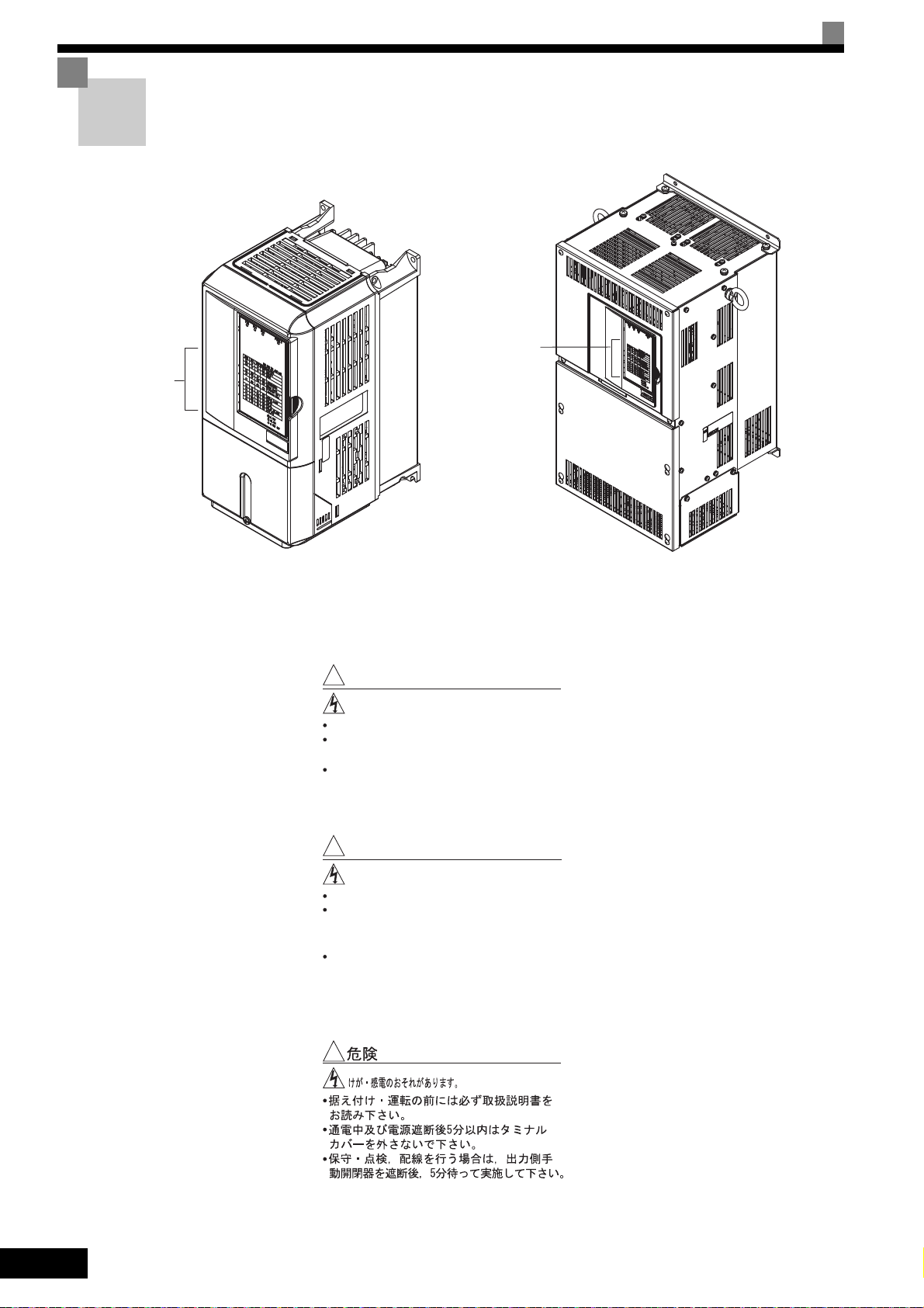
Warning Labels on the Inverter
Warnings
listed
here
CIMR-L7B23P7 (example)
CIMR-L7B2022 (example)
!
WARNING
Risk of electric shock.
Read manual before installing.
Wait 5 minutes for capacitor discharge
after disconnecting power supply.
After opening the manual switch between
the drive and motor, please wait 5 minutes
before inspecting, performing maintenance
or wiring the drive.
!
AVERTISSEMENT
Risque de décharge électrique.
Lire le manuel avant l' installation.
Attendre 5 minutes aprés la coupure de
l' allmentation. Pour permettre la
décharge des condensateurs.
Après avoir déconnécte la protection
entra le drive et le moteur, veuillez
patienter 5 minutes avant d' inspecter,
d' eff
ectuer une opération de montage
ou de câblage du variateur.
!
Be sure to read and follow all warning labels on the Inverter before installation.
Warnings
listed
here
Text on Warning Labels
VIII
Page 11

Warranty Information
Free Warranty Period and Scope
Warranty Period
This product is warranted for twelve months after being delivered to Yaskawa’s customer or if
applicable eighteen months from the date of shipment from Yaskawa’s factory whichever comes
first.
Scope of Warranty
Inspections
Periodic inspections must be conducted by the customer. However, upon request, Yaskawa or
one of Yaskawa’s Service Centers can inspect the product for a fee. In this case, if after conferring with the customer, a Yaskawa product is found to be defective due to Yaskawa workmanship or materials and the defect occurs during the warranty period, then this fee will be waived
and the problem remedied free of charge.
Repairs
If a Yaskawa product is found to be defective due to Yaskawa workmanship or materials and the
defect occurs during the warranty period, Yaskawa will provide a replacement, repair the defective product, and provide shipping to and from the site free of charge.
However, if the Yaskawa Authorized Service Center determines that the problem with a
Yaskawa product is not due to defects in Yaskawa’s workmanship or materials, then the customer will be responsible for the cost of any necessary repairs. Some problems that are outside
the scope of this warranty are:
• Problems due to improper maintenance or handling, carelessness, or other reasons where the
customer is determined to be responsible.
• Problems due to additions or modifications made to a Yaskawa product without Yaskawa’s
understanding.
• Problems due to the use of a Yaskawa product under conditions that do not meet the recommended specifications.
• Problems caused by natural disaster or fire.
• Or other problems not due to defects in Yaskawa workmanship or materials.
Exceptions
Restrictions
Warranty service is only applicable within Japan.
However, after-sales service is available for customers outside of Japan for a reasonable fee.
Contact your local Yaskawa representative for more information.
Any inconvenience to the customer or damage to non-Yaskawa products due to Yaskawa's
defective products whether within or outside the warranty period are NOT covered by this warranty.
• This Inverter does not guarantee performance of the entire elevator system.
• Proper safety measure must be taken on the upper controller side of the hoist application.
• The swing suppression and noise preventative features in this Inverter do not guarantee passenger comfort.
• The Varispeed L7 was not designed or manufactured for use in devices or systems that may
directly affect or threaten human lives or health.
• Customers who intend to use the product described in this manual for devices or systems relating to transportation, health care, space aviation, atomic or electric power, or underwater use
must contact their Yaskawa representatives or the nearest Yaskawa sales office beforehand.
• This product has been manufactured under strict quality-control guidelines. However, if this
product is to be installed in any location where failure of this product could involve or result
in a life-and-death situation or loss of human life or in a facility where failure may cause a
serious accident or physical injury, safety devices must be installed to minimize the likelihood
of any accident.
IX
Page 12

Registered Trademarks
The following registered trademarks are used in this manual.
• DeviceNet is a registered trademark of the ODVA (Open DeviceNet Vendors Association, Inc.).
• InterBus is a registered trademark of Phoenix Contact Co.
• Profibus is a registered trademark of Siemens AG.
• HIPERFACE
®
is a registered trademark of STEGMANN Incorporated.
X
Page 13

Contents
Safety Information ..........................................................................................II
Safety Precautions ........................................................................................III
Warning Labels on the Inverter ................................................................... VIII
Warranty Information .................................................................................... IX
Registered Trademarks ................................................................................. X
1 Handling Inverters ................................................................. 1-1
Varispeed L7 Models ...................................................................................1-2
Permanent magnet motor Application Example ..........................................1-3
Permanent magnet motor Application Example ............................................................1-3
Confirmations upon Delivery .......................................................................1-4
Checks ...........................................................................................................................1-4
Nameplate Information ..................................................................................................1-4
Component Names ........................................................................................................1-6
Exterior and Mounting Dimensions ..............................................................1-8
Open Chassis Inverters (IP00) ......................................................................................1-8
Enclosed Wall-mounted Inverters (NEMA1 / IP20) ........................................................1-8
Checking and Controlling the Installation Site ...........................................1-10
Installation Site ............................................................................................................1-10
Controlling the Ambient Temperature ..........................................................................1-10
Protecting the Inverter from Foreign Matter .................................................................1-10
Installation Orientation and Space ............................................................. 1-11
Removing and Attaching the Terminal Cover ............................................1-12
Removing the Terminal Cover .....................................................................................1-12
Attaching the Terminal Cover .......................................................................................1-12
Removing/Attaching the Digital Operator/LED Monitor and Front Cover ..1-13
Inverters of 18.5 kW or Less ........................................................................................1-13
Inverters of 22 kW or More ..........................................................................................1-15
2 Wiring ...................................................................................... 2-1
Connections to Peripheral Devices .............................................................2-2
Connection Diagram ....................................................................................2-3
Terminal Block Configuration .......................................................................2-5
Wiring Main Circuit Terminals ......................................................................2-6
Applicable Wire Sizes and Closed-loop Connectors .....................................................2-6
Main Circuit Terminal Functions ..................................................................................2-10
Main Circuit Configurations ..........................................................................................2-11
Standard Connection Diagrams ...................................................................................2-12
Wiring the Main Circuits ...............................................................................................2-13
XI
Page 14

Wiring Control Circuit Terminals ................................................................ 2-18
Wire Sizes ................................................................................................................... 2-18
Control Circuit Terminal Functions .............................................................................. 2-20
Control Circuit Terminal Connections .......................................................................... 2-23
Control Circuit Wiring Precautions .............................................................................. 2-24
Wiring Check .............................................................................................2-25
Checks ........................................................................................................................ 2-25
Installing and Wiring Option Cards ............................................................ 2-26
Option Card Models and Specifications ...................................................................... 2-26
Installation ...................................................................................................................2-26
PG Speed Control Board Terminals and Specifications .............................................. 2-28
Wiring .......................................................................................................................... 2-30
Wiring the Terminal Blocks .......................................................................................... 2-34
Selecting the Number of PG (Encoder) Pulses ........................................................... 2-35
3 LED Monitor/Digital Operator and Modes ............................3-1
LED Monitor JVOP-163 ............................................................................... 3-2
LED Monitor .................................................................................................................. 3-2
LED Display Examples .................................................................................................. 3-2
Digital Operator JVOP-160 ..........................................................................3-3
Digital Operator Display ................................................................................................ 3-3
Digital Operator Keys .................................................................................................... 3-3
Inverter Modes .............................................................................................................. 3-6
Switching Modes ........................................................................................................... 3-7
Drive Mode ....................................................................................................................3-8
Quick Programming Mode ............................................................................................. 3-9
Advanced Programming Mode .................................................................................... 3-10
Example Operations .................................................................................................... 3-10
Verify Mode ................................................................................................................. 3-12
Autotuning Mode ......................................................................................................... 3-13
4 Trial Operation ........................................................................4-1
Overview of Trial Operation Procedure ....................................................... 4-2
Performing a Trial Operation ......................................................................4-3
Turning on the Power .................................................................................................... 4-3
Display at Power Up ...................................................................................................... 4-3
Basic Settings ................................................................................................................ 4-4
Setting Motor Related Parameters ................................................................................ 4-6
Application Settings ..................................................................................................... 4-20
No-load Operation ....................................................................................................... 4-21
Loaded Operation ........................................................................................................ 4-21
Check and Recording User Parameters ...................................................................... 4-22
XII
Performance Optimization ......................................................................... 4-23
Page 15

5 Parameters ............................................................................. 5-1
Parameter Descriptions ...............................................................................5-2
Description of Parameter Tables ....................................................................................5-2
Digital Operation Display Functions and Levels ..........................................5-3
Parameters Available in Quick Programming Mode ......................................................5-4
Parameter Tables ......................................................................................5-10
A: Setup Settings .........................................................................................................5-10
Application Parameters: b ............................................................................................5-12
Tuning Parameters: C ..................................................................................................5-15
Reference Parameters: d .............................................................................................5-21
Motor Parameters: E ....................................................................................................5-23
Option Parameters: F ..................................................................................................5-26
Terminal Function Parameters: H ................................................................................5-31
Protection Function Parameters: L ..............................................................................5-38
N: Special Adjustments ................................................................................................5-45
Digital Operator/LED Monitor Parameters: o ...............................................................5-47
Elevator Function Parameters: S .................................................................................5-51
U: Monitor Parameters .................................................................................................5-58
Factory Settings that Change with the Control Method (A1-02) .................................. 5-66
Parameters that change with V/f patterns ....................................................................5-68
Factory Settings that Change with the Inverter Capacity (o2-04) ................................5-73
6 Parameter Settings by Function ........................................... 6-1
Carrier Frequency Derating and Current Limitation .....................................6-2
Carrier Frequency Setting ..............................................................................................6-2
Current limitation level at low speeds ............................................................................6-3
EN81-1 Compliance ....................................................................................6-4
Control/Brake Sequence .............................................................................6-6
Up and Down Commands ..............................................................................................6-6
Speed Reference Source Selection ...............................................................................6-7
Speed Selection Sequence Using Multi-function Contact Inputs ...................................6-8
Fast Stop ......................................................................................................................6-13
Inspection RUN ............................................................................................................6-14
Brake Sequence ..........................................................................................................6-15
Short Floor Operation ..................................................................................................6-21
Acceleration and Deceleration Characteristics ..........................................6-23
Setting Acceleration and Deceleration Times ..............................................................6-23
Acceleration and S-curve Settings ...............................................................................6-26
Output Speed Hold (Dwell Function) ...........................................................................6-27
Stall Prevention During Acceleration ...........................................................................6-28
Adjusting Analog Input Signals ..................................................................6-30
Adjusting Analog Frequency References ....................................................................6-30
XIII
Page 16

Speed Detection and Speed Limitation .....................................................6-32
Speed Agreement Function ......................................................................................... 6-32
Limiting the Elevator Speed ......................................................................................... 6-34
Improving the Operation Performance ...................................................... 6-35
Droop Control Function ............................................................................................... 6-35
Reducing the Motor Speed Fluctuation (Slip Compensation Function) ....................... 6-36
Torque Compensation Function Adjustments .............................................................. 6-39
Automatic Speed Regulator (ASR) (Closed-loop Vector only) .................................... 6-41
A/D Conversion Delay Time Tuning ............................................................................ 6-43
Torque Compensation Reduction at Stop .................................................................... 6-44
Stabilizing Speed (Automatic Frequency Regulator) (Open-loop Vector) .................... 6-45
Inertia Compensation (Closed-loop Vector only) ......................................................... 6-47
Improving the Leveling Accuracy by Slip Compensation ............................................ 6-48
Field Forcing ................................................................................................................ 6-49
Adjusting the DC Injection Current .............................................................................. 6-50
Motor Rotation Direction Change ................................................................................ 6-51
Protective Functions .................................................................................. 6-52
Preventing Motor Stalling During Operation ................................................................ 6-52
Operation Selection at Frequency Reference Loss ..................................................... 6-53
Motor Torque Detection/Car Stuck Detection .............................................................. 6-53
Limiting the Motor Torque (Torque Limit Function) ...................................................... 6-57
Internal Cooling Fan Failure OH1 Detection ............................................................... 6-58
Motor Overload Protection .......................................................................................... 6-60
Output Current Observation ........................................................................................ 6-62
Inverter Protection .....................................................................................6-64
Inverter Overheat Protection ....................................................................................... 6-64
Output Open Phase Protection ................................................................................... 6-64
Ground Fault Protection .............................................................................................. 6-65
Cooling Fan Control .................................................................................................... 6-66
Setting the Ambient Temperature ............................................................................... 6-67
Over Acceleration Detection (DV6 Fault Detection) .................................................... 6-67
Selection of Conditions for Detection of Excessive Speed Deviation .......................... 6-68
Input Terminal Functions ........................................................................... 6-69
Closing the Inverter Output (Baseblock) ..................................................................... 6-69
Stopping the Inverter on External Device Errors (External Fault Function) ................. 6-70
Using the Timer Function ............................................................................................ 6-71
Magnetic Contactor Answer Back Detection ............................................................... 6-72
Output Terminal Functions ........................................................................ 6-73
Magnetic Position Detection Status Signal .................................................................. 6-76
Motor and V/f Pattern Setup ...................................................................... 6-77
Setting Motor Parameters ........................................................................................... 6-77
Autotuning ................................................................................................................... 6-79
Setting the V/f Pattern ................................................................................................. 6-83
XIV
Page 17

Digital Operator/LED Monitor Functions ....................................................6-85
Setting Digital Operator/LED Monitor Functions ..........................................................6-85
Copying Parameters (JVOP-160 only) ........................................................................6-89
Prohibiting Overwriting of Parameters .........................................................................6-93
Setting a Password ......................................................................................................6-94
Displaying User-set Parameters Only ..........................................................................6-95
Machine Data Copy Function ......................................................................................6-95
PG Option Cards .......................................................................................6-97
Setting the Absolute Encoder Resolution (F1-21) .....................................................6-100
Emergency Operation ..............................................................................6-101
Automatic Fault Reset .............................................................................6-105
UV1 Fault Reset Operation Selection Function ........................................................6-106
MEMOBUS Communications ..................................................................6-107
RS-422/485 Interface .................................................................................................6-107
7 Troubleshooting .................................................................... 7-1
Protective and Diagnostic Functions ...........................................................7-2
Fault Detection ...............................................................................................................7-2
Alarm Detection .............................................................................................................7-9
Operator Programming Errors .....................................................................................7-12
Autotuning Faults ........................................................................................................7-13
Digital Operator Copy Function Faults .........................................................................7-15
Machine Data Copy Function Faults ......................................... 7-16
Troubleshooting .........................................................................................7-17
If A Parameter Cannot Be Set .....................................................................................7-17
If the Motor Does Not Operate Properly ......................................................................7-18
If the Direction of the Motor Rotation is Reversed .......................................................7-18
If the Motor Stalls or Acceleration is Slow ....................................................................7-18
If Motor Deceleration is Slow .......................................................................................7-19
Motor torque is insufficient. ..........................................................................................7-19
If the Motor Overheats .................................................................................................7-19
If Peripheral Devices are Influenced by the Starting or Running Inverter ....................7-20
If the Earth Leakage Breaker Operates When the Inverter is Running .......................7-20
If There is Mechanical Oscillation ................................................................................7-20
8 Maintenance and Inspection ................................................. 8-1
Maintenance and Inspection ........................................................................8-2
Periodic Inspection ........................................................................................................8-2
Periodic Maintenance of Parts .......................................................................................8-3
Types and Number of Cooling Fans Used in the Inverter ..............................................8-4
Cooling Fan Replacement Outline .................................................................................8-5
Circulation Fan Replacement Outline ..........................................................................8-10
Removing and Mounting the Control Circuit Terminal Board .......................................8-12
XV
Page 18

9 Specifications .........................................................................9-1
Inverter Specifications ................................................................................. 9-2
Specifications by Model ................................................................................................. 9-2
Common Specifications ................................................................................................. 9-4
10 Appendix ...............................................................................10-1
Inverter Application Precautions ...............................................................10-2
Selection ...................................................................................................................... 10-2
Installation ................................................................................................................... 10-2
Settings ....................................................................................................................... 10-2
Handling ...................................................................................................................... 10-3
Motor Application Precautions ..................................................................10-4
Using the Inverter for an Existing Standard Motor ....................................................... 10-4
Using the Inverter for Special Motors .......................................................................... 10-4
Power Transmission Mechanism (Speed Reducers, Belts, and Chains) .................... 10-4
EMC Compatibility ..................................................................................... 10-5
Line Filters .................................................................................................10-7
User Parameters .......................................................................................10-9
Revision History
XVI
Page 19

1
Handling Inverters
This chapter describes the checks required upon receiving or installing an Inverter.
Varispeed L7 Models ..........................................................1-2
Permanent magnet motor Application Example..................1-3
Confirmations upon Delivery...............................................1-4
Exterior and Mounting Dimensions .....................................1-8
Checking and Controlling the Installation Site ..................1-10
Installation Orientation and Space ....................................1-11
Removing and Attaching the Terminal Cover ...................1-12
Removing/Attaching the Digital Operator/ LED Monitor and
Front Cover .......................................................................1-13
Page 20
1
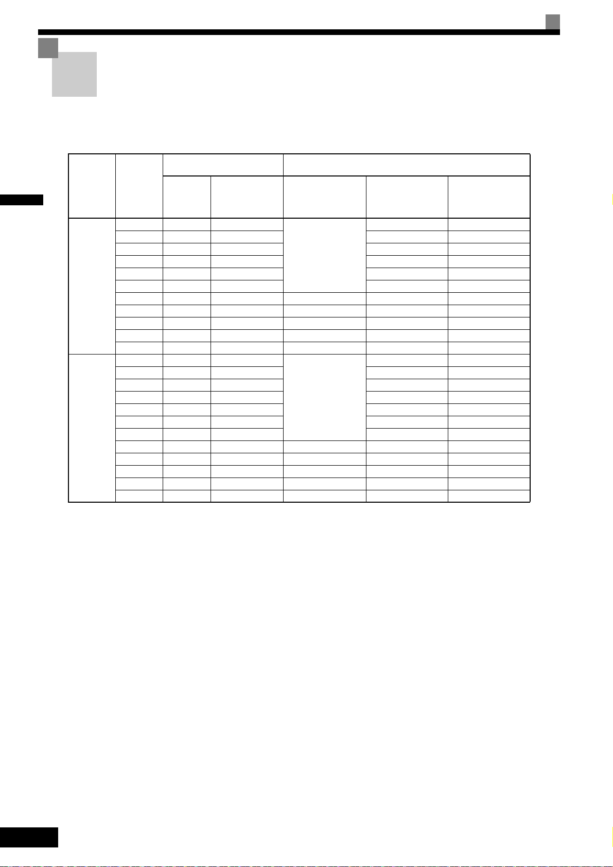
Varispeed L7 Models
The Varispeed L7 Series includes Inverters in two voltage classes: 200 V and 400 V. The maximum motor capacities
vary from 3.7 to 55 kW (23 models).
Table 1.1 Varispeed L7 Models
Maximum
Voltage
Class
200 V class
400 V class
* 200 V/400 V class 30KW-55KW model is developing.
Motor
Capacity
kW
3.7 7 CIMR-L7B23P7
5.5 10 CIMR-L7B25P5 25P51 25P57
7.5 14 CIMR-L7B27P5 27P51 27P57
11 20 CIMR-L7B2011 20111 20117
15 27 CIMR-L7B2015
18.5 33 CIMR-L7B2018 20181 20187
22 40 CIMR-L7B2022 20220 20221 20227
30 54 CIMR-L7B2030 20300 20301 20307
37 67 CIMR-L7B2037 20370 20371 20377
45 76 CIMR-L7B2045 20450 20451 20457
55 93 CIMR-L7B2055 20550 20551 20557
3.7 7 CIMR-L7B43P7
4.0 9 CIMR-L7B44P0 44P01 43P77
5.5 12 CIMR-L7B45P5 45P51 45P57
5 15 CIMR-L7B47P5 47P51 47
7.
11 22 CIMR-L7B4011 40111 40117
15 28 CIMR-L7B4015 40151 40157
18.5 34 CIMR-L7B4018 40181 40187
22 40 CIMR-L7B4022 40220 40221 40227
30 54 CIMR-L7B4030 40300 40301 40307
37 67 CIMR-L7B4037 40370 40371 40377
45 80 CIMR-L7B4045 40450 40451 40457
55 106 CIMR-L7B4055 40550 40551 40557
Varispeed L7
Output
Capacity
kVA
Basic Model
Number
(Always specify through the protective structure when ordering.)
Open Chassis
(IEC IP00)
CIMR-L7B
Remove the top and
bottom covers from the
Enclosed Wall-mounted
model.
Remove the top and bot-
tom covers from the
Enclosed Wall-mount
model.
Specifications
Enclosed Wall-
mounted
(NEMA 1)
CIMR-L7B
23P71 23P77
20151
43P71 43P77
Enclosed Wall-
mounted
(IEC IP20)
CIMR-L7B
20157
P57
1-2
Page 21

Permanent magnet motor Application Example
Permanent magnet motor Application Example
Permanent magnet motor Application Example
The table below lists which models of Yaskawa’s standard SPM motors correspond with which models of
EnDat encoders.
Application Examples: Yaskawa SPM Motors and EnDat Encoders
Load Capacity
kg
200 V Class
450
600
750
900
1000
400 V Class
450
600
750
900
1000
Elevator Speed
m/min
45 2.1 72 22P1072
60 2.8 96 22P8096
90 4.2 144 24P2144
45 2.8 72 22P8072
60 3.7 96 23P7096
90 5.6 144 25P6144
105 6.5 168 26P5168
45 3.5 72 23P5072
60 4.6 96 24P6096
90 6.9 144 26P9144
105 8.1 168 28P1168
45 4.2 72 24P2072
60 5.6 96 25P6096
90 8.3 144 28P3144
105 9.7 168 29P7168
45 4.6 72 24P6072
60 6.2 96 26P2096
90 9.2 144 29P2144
105 11 168 2011168
45 2.1 72 42P1072
60 2.8 96 42P8096
90 4.2 144 44P2144 47P5
45 2.8 72 42P8072
60 3.7 96 43P7096
90 5.6 144 45P6144
105 6.5 168 46P5168
45 3.5 72 43P5072
60 4.6 96 44P6096
90 6.9 144 46P9144
105 8.1 168 48P1168
45 4.2 72 44P2072
60 5.6 96 45P6096
90 8.3 144 48P3144
105 9.7 168 49P7168
45 4.6 72 44P6072
60 6.2 96 46P2096
90 9.2 144 49P2144
105 11 168 4011168
Motor Output *1
kW
Revolutions per
Minute *2
-1
min
Motor Model
SSE4--F21
Inverter Model
CIMR-L7B
25P5
27P5
2011
27P5
2015
2011
2015
2011
2018
45P5
45P5
4011
47P5
4011
4015
4011
4015
1
* 1. 105 m/min up to 1000 kg.
* 2. Sheave diameter of 400 m with a roping ratio of 2:1.
1-3
Page 22
1
Inverter model
Inverter
specifications
Mass
Input s pecification
Output specification
Serial number
UL file numbe r
Lot number
MADE IN JA PAN
YASKAWA ELECTRIC CORPORARION
SPEC: 43P77A
PRG:
M
s
MASS: 4.0 kg
CIMR-L7B43P7
AC3PH 380-480V 50/60Hz 10.2A
AC3PH 0-480V 0-120Hz 8.5A 3min. 50%ED 8.5kVA
FILE NO E131457
INPUT
OUTPUT
O/N
S/N
MODEL
Confirmations upon Delivery
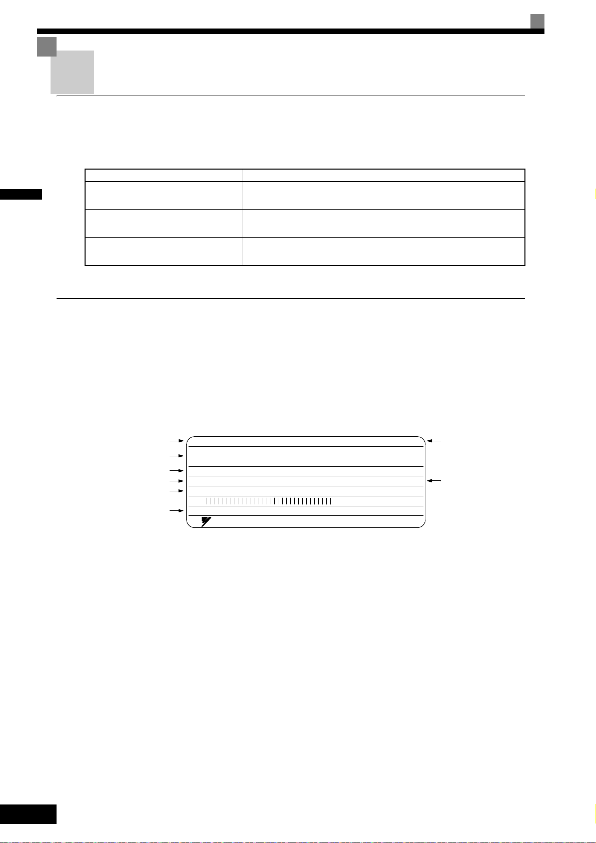
Checks
Check the following items as soon as the Inverter is delivered.
Table 1.2 Checks
Item Method
Has the correct model of Inverter been
delivered?
Is the Inverter damaged in any way?
Check the model number on the nameplate on the side of the Inverter.
Inspect the entire exterior of the Inverter to see if there are any scratches or
other damage resulting from shipping.
Are any screws or other components
loose?
Use a screwdriver or other tools to check for tightness.
If you find any irregularities in the above items, contact the agency from which you purchased the Inverter.
Nameplate Information
There is a nameplate attached to the side of each Inverter. The nameplate shows the model number, specifications, lot number, serial number, and other information about the Inverter.
Example Nameplate
The following nameplate is an example for a standard domestic European Inverter: 3-phase, 400 VAC,
3.7 kW, IEC IP20 standards
1-4
Fig 1.1 Nameplate
Page 23
Confirmations upon Delivery
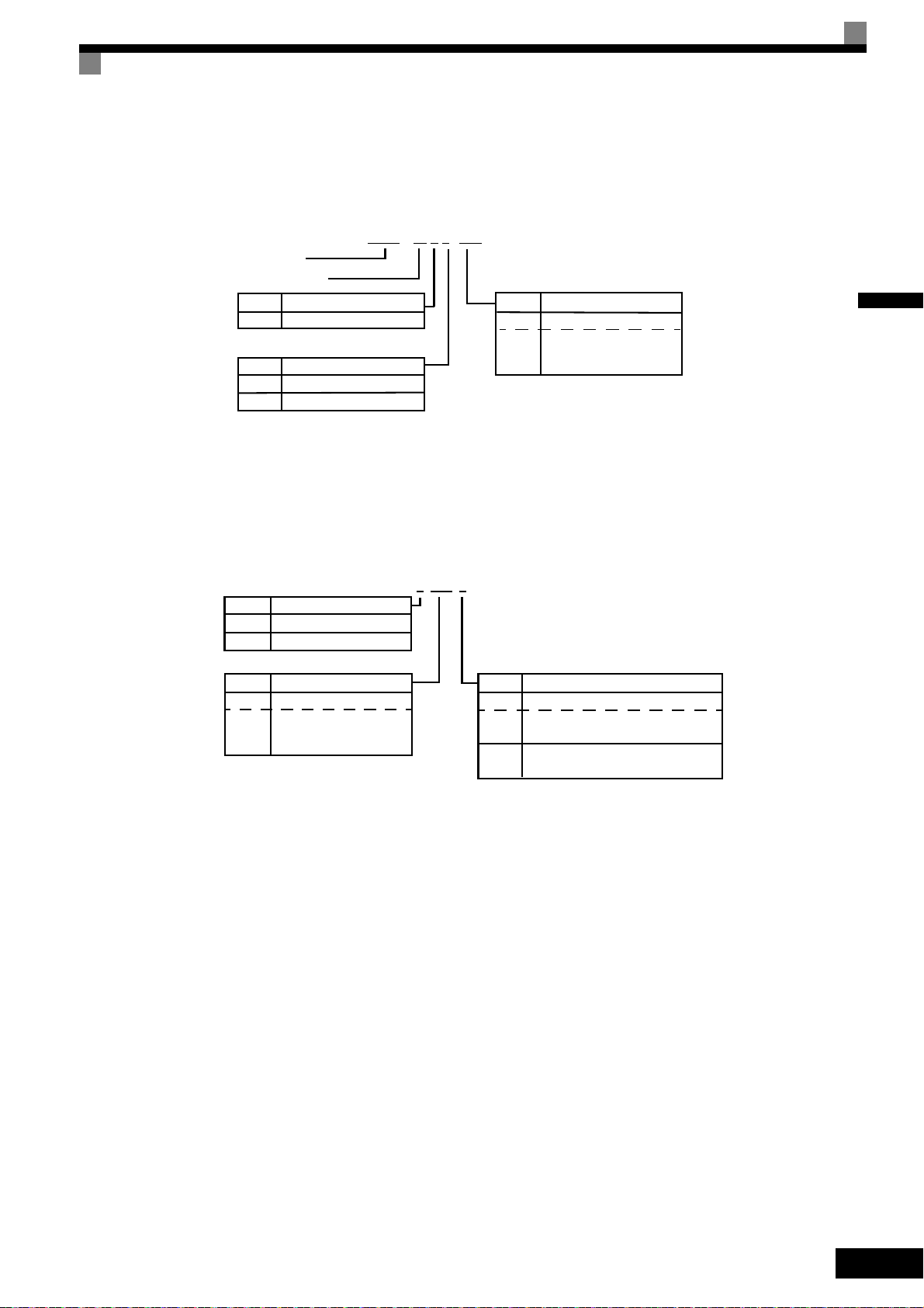
CIMR – L7 B 2 3P7
Inverter
Varispeed L7
No.
B
Specification
IM Motor (PG optional)
No.
Voltage Class
2
4
AC Input, 3-phase, 200 V
AC Input, 3-phase, 400 V
No.
Max. Motor Capacity
3P7
3.7 kW
5P5
5.5 kW
to
to
55
55 kW
“P” Indicates the decimal point.
2 3P7 1
No.
2
4
Voltage Class
AC Input, 3-phase, 200 V
AC Input, 3-phase, 400 V
No.
Max. Motor Capacity
3P7
3.7 kW
5P5
5.5 kW
to
to
55
55 kW
No.
Protective Structure
0
Open chassis (IEC IP00)
1
Enclosed wall-mounted
(NEMA Type 1)
“P” Indicates the decimal point
7
(IEC IP20)
Enclosed wall-mounted
Inverter Model Numbers
The model number of the Inverter on the nameplate indicates the specification, voltage class, and maximum
motor capacity of the Inverter in alphanumeric codes.
Fig 1.2 Inverter Model Numbers
1
Inverter Specifications
The Inverter specifications (“SPEC: A”) on the nameplate indicate the voltage class, maximum motor capacity, the protective structure, and the revision of the Inverter in alphanumeric codes.
Fig 1.3 Inverter Specifications
1-5
Page 24
1
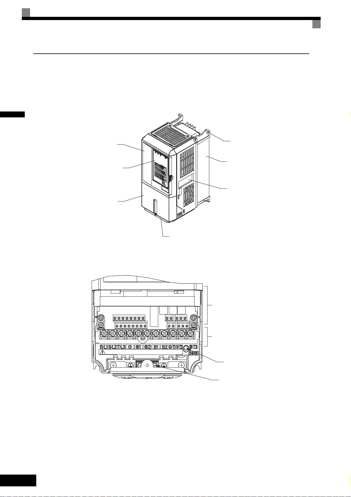
Front cover
Digital Operator
Terminal cover
Bottom protective cover
Nameplate
Diecast cover
Mounting
Control circuit terminals
Main circuit terminals
Ground terminal
Charge indicator
Component Names
Inverters of 18.5 kW or Less
The external appearance and component names of the Inverter are shown in Fig 1.4. The Inverter with the terminal cover removed is shown in Fig 1.5.
Fig 1.4 Inverter Appearance (18.5 kW or Less)
Fig 1.5 Terminal Arrangement (18.5 kW or Less)
1-6
Page 25

Confirmations upon Delivery
Front cover
Inveter cover
Digital Operator
Terminal cover
Nameplate
Cooling fan
Mounting holes
Control
circuit
terminals
Charge indicator
Ground terminals
Main
circuit
terminals
Inverters of 22 kW or More
The external appearance and component names of the Inverter are shown in Fig 1.6. The Inverter with the terminal cover removed is shown in Fig 1.7.
1
Fig 1.6 Inverter Appearance (22 kW or More)
Fig 1.7 Terminal Arrangement (22 kW or More)
1-7
Page 26
1
200 V Class Inverters of 22 or 55 kW
400 V Class Inverters of 22 to 55 kW
200 V/400 V Class Inverters of 3.7 to 18.5 kW
200 V Class Inverters of 22 or 55 kW
400 V Class Inverters of 22 to 55 kW
200 V/400 V Class Inverters of 3.7 to 18.5 kW
Grommet
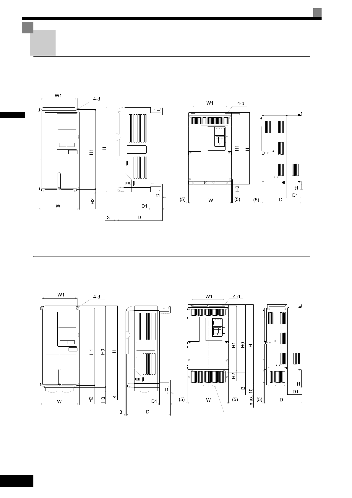
Exterior and Mounting Dimensions
Open Chassis Inverters (IP00)
Exterior diagrams of the Open Chassis Inverters are shown below.
Fig 1.8 Exterior Diagrams of Open Chassis Inverters
Enclosed Wall-mounted Inverters (NEMA1 / IP20)
Exterior diagrams of the Enclosed Wall-mounted Inverters (NEMA1 / IP20) are shown below.
1-8
Fig 1.9 Exterior Diagrams of Enclosed Wall-mounted Inverters
Page 27
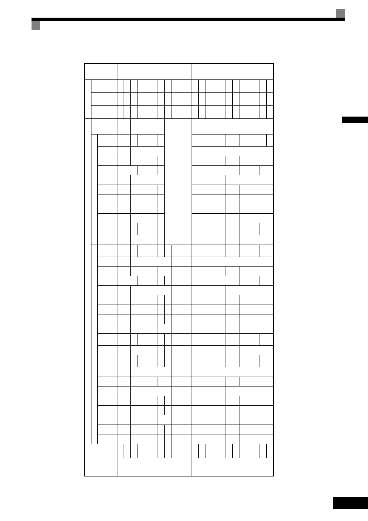
Exterior and Mounting Dimensions
Voltage
Class
Max.
Appli-
cable
Motor
Output
[kW]
Dimensions (mm) Caloric Value (W)
Cool-
ing
Method
Open Chassis (IP00) Enclosed Wall-mounted (NEMA1) Enclosed Wall-mounted (IP20)
Mount-
ing
Holes
d*
Exter-
nal
Inter-
nal
To ta l
Heat
Gen-
era-
tion
W H D W1H1H2D1 t1
App-
rox.
Mass
W H D W1H0H1H2H3D1 t1
App-
rox.
Mass
W H D W1H0H1H2H3D1 t1
App-
rox.
Mass
200 V
(3-phase)
3.7
140 280 177 126 266 7 59 5 4 140 280 177 126 280 266 7
0
59 5 4 140 280 177 126 280 266 7
0
59 5 4 M5
112 74 186
Fan
5.5 164 84 248
7.5
200 300 197 186 285
7.5
65.5
2.3
6
200
300
197 186 300 285 8 65.5
2.3
6
200
300
197 186 300 285 8 65.5
2.3
6
M6
219 113 332
11 7 310 10 7 310 10 7 374 170 544
15
240 350 207 216 335 78 11 240
350
207 216 350 335
7.5
0
78 11 240
350
207 216 350 335
7.5
0
78 11
429 183 612
18.5 380 30 380 30 501 211 712
22 250 400
258
195 385
100
17 254 535
258
195 400 385 135
100
20 254 464 258 195 400 385 64 100 19 586 274 860
30 275 450 220 435 20 279 615 220 450 435 165 23 865 352 1217
37
375 600
298
250 575
12.5
100
3.2
52
380 809
298
250
600 575
12.5
209
100
3.2
57 1015
411 1426
45 328
130
57 328
130
62 1266 505 1771
55 450 725 348 325 700 78 453 1027 350 325 725 700 302 86 1588 619 2207
400 V
(3-phase)
3.7
140 280 177 126 266 7 59 5 4 140 280 177 126 280 266 7
0
59 5 4 140 280 177 126 280 266 7
0
59 5 4 M5
80 68 148
Fan
4.0 91 70 161
5.5 127 82 209
7.5
200 300 197 186 285 8 65.5
2.3
6 200 300 197 186 300 285 8 65.5
2.3
6 200 300 197 186 300 285 8 65.5
2.3
6
M6
193 114 307
11 252 158 410
15
240 350 207 216 335
7.5
78 10 240 350 207 216 350 335
7.5
78 10 240 350 207 216 350 335
7.5
78 10
326 172 498
18.5 426 208 634
22
275 450 258 220 435 100 17 279 535 258 220 450 435
85
100 20 279 514.5 258 220 450 435
64
100 19
466 259 725
30 678 317 995
37
325 550 283 260 535 105
31
329
635
283 260 550 535 105
35
329
614
283 260 550 535 105
34
784 360 1144
45
30 715 165 34 629.5 79.5
901 415 1316
55 33 1203 495 1698
Table 1.3 Inverter Dimensions (mm) and Masses (kg)
1
1-9
Page 28

Checking and Controlling the Installation Site
Install the Inverter in the installation site described below and maintain optimum conditions.
Installation Site
1
Install the Inverter under the following conditions in a pollution degree 2 environment.
Table 1.4 Installation Site
Type Ambient Operating Temperature Humidity
Enclosed wall-mounted
(NEMA1)
Open chassis and IEC IP20 -10 to + 45 °C 95% RH or less (no condensation)
Protection covers are attached to the top and bottom of the Inverter. Be sure to remove the protection covers
before installing a 200 or 400 V Class Inverter with an output of 18.5 kW or less in a panel.
Observe the following precautions when mounting the Inverter.
• Install the Inverter in a clean location which is free from oil mist and dust. It can be installed in a totally
enclosed panel that is completely shielded from floating dust.
• When installing or operating the Inverter, always take special care so that metal powder, oil, water, or other
foreign matter does not get into the Inverter.
• Do not install the Inverter on combustible material, such as wood.
• Install the Inverter in a location free from radioactive materials and combustible materials.
• Install the Inverter in a location free from harmful gasses and liquids.
• Install the Inverter in a location without excessive oscillation.
• Install the Inverter in a location free from chlorides.
• Install the Inverter in a location not in direct sunlight.
-10 to + 40 °C 95% RH or less (no condensation)
Controlling the Ambient Temperature
To enhance the reliability of operation, the Inverter should be installed in an environment free from extreme
temperature increases. If the Inverter is installed in an enclosed environment, such as a cabinet, use a cooling
fan or air conditioner to maintain the internal air temperature below 45°C.
Protecting the Inverter from Foreign Matter
Place a cover over the Inverter during installation to shield it from metal power produced by drilling.
Always remove the cover from the Inverter after the completion of the installation. Otherwise, ventilation will
be reduced, causing the Inverter to overheat.
1-10
Page 29
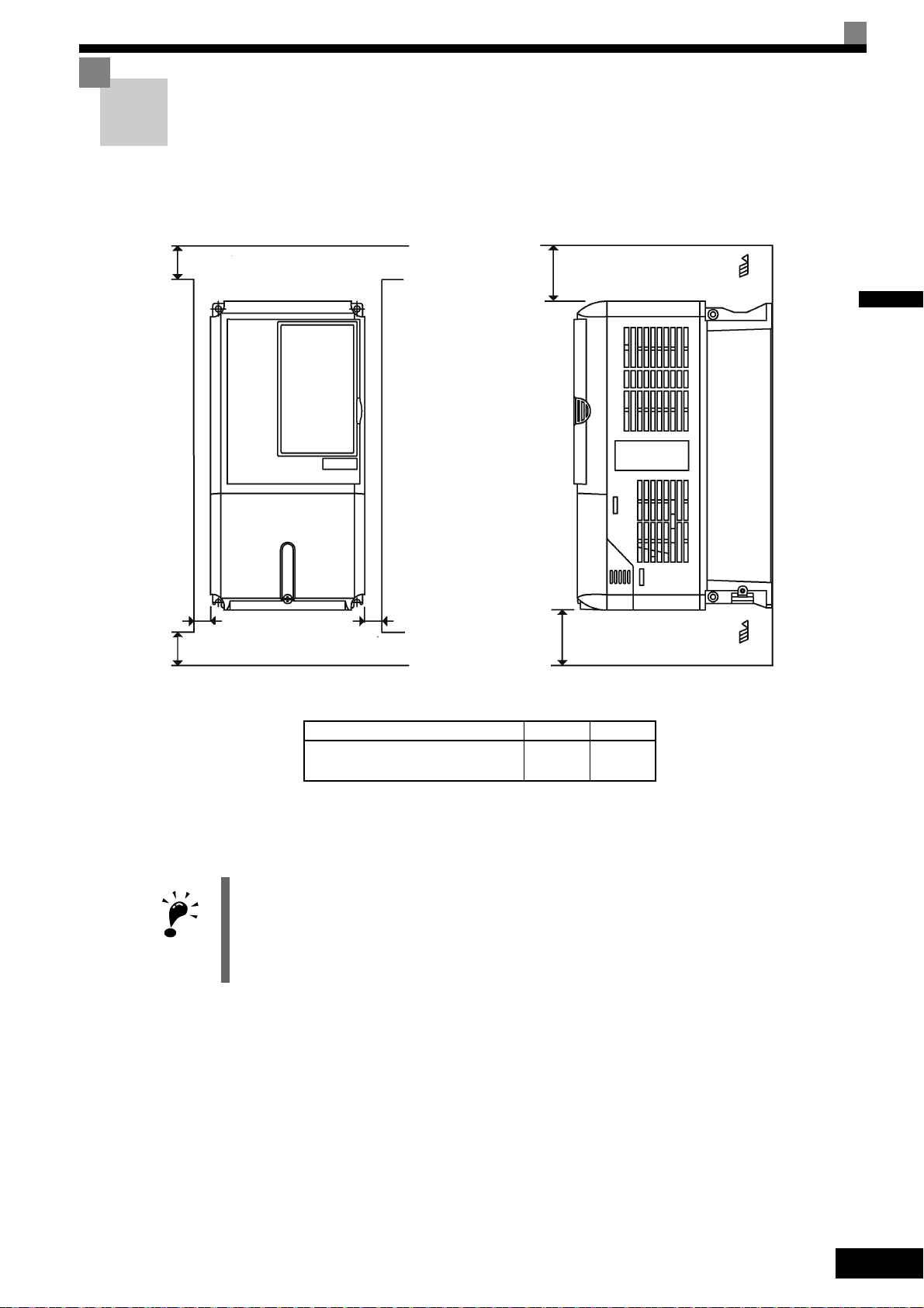
Installation Orientation and Space
IMPORTANT
A
50 mm min.
30 mm min.
30 mm min.
B
120 mm min.
Air
Air
Vertical Space
Horizontal Space
AB
200 V Class Inverter, 3.7 to 55 kW
400 V Class Inverter, 3.7 to 55 kW
50 mm 120 mm
Installation Orientation and Space
Install the Inverter vertically so as not to reduce the cooling effect. When installing the Inverter, always provide the following installation space to allow normal heat dissipation.
1
Fig 1.10 Inverter Installation Orientation and Space
1. The same space is required horizontally and vertically for both Open Chassis (IP00) and Enclosed Wallmounted (IP20, NEMA 1) Inverters.
2. Always remove the protection covers before installing a 200 or 400 V Class Inverter with an output of
18.5 kW or less in a panel.
Always provide enough space for suspension eye bolts and the main circuit lines when installing a 200 or
400 V Class Inverter with an output of 22 kW or more in a panel.
1-11
Page 30

Removing and Attaching the Terminal Cover
1
1
2
2
1
Remove the terminal cover to wire cables to the control circuit and main circuit terminals.
Removing the Terminal Cover
1
Inverters of 18.5 kW or Less
Loosen the screw at the bottom of the terminal cover, press in on the sides of the terminal cover in the directions of arrows 1, and then lift up on the terminal in the direction of arrow 2.
Fig 1.11 Removing the Terminal Cover (Model CIMR-L7B43P7 Shown Above)
Inverters of 22 kW or More
Loosen the screws on the left and right at the top of the terminal cover, pull out the terminal cover in the direction of arrow 1 and then lift up on the terminal in the direction of arrow 2.
1-12
Fig 1.12 Removing the Terminal Cover (Model CIMR-L7B4022 Shown Above)
Attaching the Terminal Cover
When the terminal block wiring has been completed, attach the terminal cover by reversing the removal procedure.
For Inverters with an output of 18.5 kW or less, insert the tab on the top of the terminal cover into the groove
on the Inverter and press in on the bottom of the terminal cover until it clicks into place.
Page 31

Removing/Attaching the Digital Operator/ LED Monitor and Front Cover
2
1
Removing/Attaching the Digital Operator/
LED Monitor and Front Cover
Inverters of 18.5 kW or Less
To attach optional boards or change the control circuit terminal board connector, remove the Digital Operator/
LED Monitor and front cover in addition to the terminal cover. Always remove the Digital Operator/LED
Monitor from the front cover before removing the front cover.
The removal and attachment procedures are described below.
Removing the Digital Operator/LED Monitor
Press the lever on the side of the Digital Operator/LED Monitor in the direction of arrow 1 to unlock the Digital Operator/LED Monitor and lift the Digital Operator/LED Monitor in the direction of arrow 2 to remove
the Digital Operator/LED Monitor as shown in the following illustration.
1
Fig 1.13 Removing the Digital Operator/LED Monitor (Model CIMR-L7B43P7 Shown Above)
1-13
Page 32

1
1
1
2
A
B
Removing the Front Cover
Press the left and right sides of the front cover in the directions of arrows 1 and lift the bottom of the cover in
the direction of arrow 2 to remove the front cover as shown in the following illustration.
Fig 1.14 Removing the Front Cover (Model CIMR-L7B43P7 Shown Above)
Mounting the Front Cover
After wiring the terminals, mount the front cover to the Inverter by performing the steps to remove the front
cover in reverse order.
1. Do not mount the front cover with the Digital Operator/LED Monitor attached to the front cover; otherwise, Digital Operator/LED Monitor may malfunction due to imperfect contact.
2. Insert the tab of the upper part of the front cover into the groove of the Inverter and press the lower part of
the front cover onto the Inverter until the front cover snaps shut.
Mounting the Digital Operator/LED Monitor
After attaching the terminal cover, mount the Digital Operator/LED Monitor onto the Inverter using the following procedure.
1. Hook the Digital Operator/LED Monitor at A (two locations) on the front cover in the direction of arrow 1
as shown in the following illustration.
2. Press the Digital Operator/LED Monitor in the direction of arrow 2 until it snaps in place at B (two locations).
Fig 1.15 Mounting the Digital Operator/LED Monitor
1-14
Page 33

Removing/Attaching the Digital Operator/ LED Monitor and Front Cover
IMPORTANT
1
2
1. Do not remove or attach the Digital Operator/LED Monitor or mount or remove the front cover using methods other than those described above, otherwise the Inverter may break or malfunction due to imperfect
contact.
2. Never attach the front cover to the Inverter with the Digital Operator/LED Monitor attached to the front
cover. Imperfect contact can result.
Always attach the front cover to the Inverter by itself first, and then attach the Digital Operator/LED Monitor to the front cover.
Inverters of 22 kW or More
For Inverters with an output of 22 kW or more, remove the terminal cover and then use the following procedures to remove the Digital Operator/LED Monitor and front cover.
Removing the Digital Operator/LED Monitor
Use the same procedure as for Inverters with an output of 18.5 kW or less.
1
Removing the Front Cover
Lift up at the location label 1 at the top of the control circuit terminal board in the direction of arrow 2.
Fig 1.16 Removing the Front Cover (Model CIMR-L7B4022 Shown Above)
Attaching the Front Cover
After completing the required work, such as mounting an optional board or setting the control circuit terminal
board, attach the front cover by reversing the procedure to remove it.
1. Confirm that the Digital Operator/LED Monitor is not mounted on the front cover. Contact faults can occur
if the cover is attached while the Digital Operator/LED Monitor is mounted to it.
2. Insert the tab on the top of the front cover into the slot on the Inverter and press in on the cover until it
clicks into place on the Inverter.
Attaching the Digital Operator/LED Monitor
Use the same procedure as for Inverters with an output of 18.5 kW or less.
1-15
Page 34

2
Wiring
This chapter describes the terminals, main circuit terminal connections, main circuit terminal wiring specifications, control circuit terminals, and control circuit wiring specifications.
Connections to Peripheral Devices.....................................2-2
Connection Diagram ...........................................................2-3
Terminal Block Configuration..............................................2-5
Wiring Main Circuit Terminals .............................................2-6
Wiring Control Circuit Terminals .......................................2-18
Wiring Check.....................................................................2-25
Installing and Wiring Option Cards ...................................2-26
Page 35

2
Power supply
Molded-case
circuit breaker
or ground fault
interrupter
Magnetic contactor (MC)
Zero phase reactor
Zero phase reactor
Motor
Ground
Input noise filter
Output noise filter
Inverter
Ground
Braking resistor
DC reactor for power
factor improvement
AC reactor for power
factor improvement
Varispeed F7
ᧂⓂ
Connections to Peripheral Devices
Examples of connections between the Inverter and typical peripheral devices are shown in Fig 2.1.
Fig 2.1 Example Connections to Peripheral Devices
2-2
Page 36

Connection Diagram
Communication
and
Control Cards
(For Option)
S1
S2
S3
S4
S5
S6
S7
BB
BB1
SC
E(G)
0㨪+10V
1
2
3
+V
A1
AC
R+
R-
S+
S-
IG
0V
M5
M6
Multi-function contact output 3
M3
M4
Multi-function contact output 2
M1
M2
Multi-function contact output 1
MA
MB
MC
TA3
TA1
TA2
1
2
3
4
5
6
7
8
9
10
1
2
3
4
5
6
7
A pulse
B pulse
Z pulse
SG
2CN
PG-X2
(Option)
Fault contact output
MA
MC
(20kΩ )
R/L1
S/L2
T/L3
U/T1
V/T2
W/T3
1 2
B1 B2
UX
P0
N0
Input voltage for control power
200 V Class: 250 to 300VDC
400 V Class: 500 to 600VDC0V
Factory setting:
Brake release command
Factory setting:
Magnetic contactor control
Factory setting:
Inverter operation ready
Min. load
5 VDC,10 mA
IM/PM
U
V
W
Motor
12V
0V
A+
AB+
BZ+
Z-
PG
R
S
T
MCCB MC
(Ground to
10 Ω max.)
Inverter
CIMR-L7B43P7
*1
*1
*1
*1
*2
*3
*4
*5
*9
*5
*6
*7
*8
+24V 8mA
+24V
2kΩ
2kΩ
3-phase power
380 to 480 V
50/60 Hz
DC reactor to
improve input power
factor (Optional)
Short-circuit Bar
Braking Resistor
unit (Optional)
Forward run/stop
Reverse run/stop
Nominal speed
Inspection Run
Intermediate speed
Leveling speed
Not used
Hardware
baseblock 1
Hardware
baseblock 2
Multi-function
contact inputs
(Factory setting)
External
frequency
reference
Frequency
setter
Frequency setting
adjustment
Shield wire
connection terminal
Frequency setting
power +15 V 20 mA
Master speed
reference 0 to 10 V
MEMOBUS
communications
RS-485/422
Terminating
resistance
Pulse monitor
output
RS-422 Level
Wiring distance:d:
30 m max.
250 VAC, 10 mA min. 1 A max.
30 VAC, 10 mA min. 1 A max.
Multi-function contact output
250 VAC, 10 mA min. 1 A max.
30 VAC, 10 mA min. 1 A max.
Min. load
5 VDC,10 mA
CN5 (NPN setting)
Example: 400 V 3.7 kW (CIMR-L7B43P7)
Connection Diagram
2
* 1. indicates shield wire and indicates twisted-pair shield wire.
* 2. Main circuit terminals are indicated with double circles and control circuit terminals are indicated with single circle.
* 3. The output current capacity of the +V and −V terminals is 20 mA. Do not short-circuit between the +V and AC terminals. Doing so may result in a mal-
* 4. The wiring for a motor with a cooling fan is not required for self-cooling motors.
* 5. Sequence input signals S1 to S7, BB, and BB1 are labeled for sequence connections (0 V common and sinking mode) for no-voltage contacts or NPN
function or a breakdown of the Inverter.
transistors. These are the factory settings.
For PNP transistor sequence connections (+24V common and sourcing mode) or to provide a 24-V external power supply, refer to page 2-22.
Fig 2.2 Connection Diagram (Model CIMR-L7B43P7 Shown Above)
2-3
Page 37

* 6. Do not ground nor connect the AC terminal on the control circuit to the unit. Doing so may result in a malfunction or a breakdown of the Inverter.
IMPORTANT
* 7. Disable the stall prevention during deceleration (set parameter L3-04 to 0) when using a Braking Resistor Unit or a Braking Unit. If this user parameter
is not changed to disable stall prevention, the system may not stop during deceleration.
* 8. During battery operation, input voltage for control power from the PO and NO terminals. The PO and NO terminals are set to the B1 (or 3) and
terminals when shipping.
* 9. To enable the Inverter, the BB and BB1 terminals must be closed. If one of the terminals is closed, "BB" will be displayed on the Digital Operator and
the Inverter will not start.
1. Control circuit terminals are arranged as shown below.
2
E(G)
2. The output current capability of the +V terminal is 20 mA.
3. Main circuit terminals are indicated with double circles and control circuit terminals are indicated with single
circles.
4. The wiring of the multi-function contact inputs S1 to S7, BB, and BB1 are shown for the connection of contacts or NPN transistors (0V common and sinking mode). This is the factory setting.
5. A DC reactor is an option only for Inverters of 18.5 kW or less. Remove the short circuit bar when connecting
a DC reactor.
6. The minimum permissible load of a multi-function contact output and an error contact output is 10 mA.
7. The master frequency reference is set to a voltage input reference as the factory setting.
R+ R-
IG S+ S-
S1 S2 S3 S4 S5 S6 S7 BB1
+V A1 ACSC SC SC BB
M5 M6 MAM1MB MCM2E(G)
M3 M4
2-4
Page 38

Terminal Block Configuration
Control circuit terminals
Main circuit terminals
Ground terminal
Charge indicator
Control
circuit
terminals
Charge indicator
Ground terminals
Main
circuit
terminals
The terminal arrangements are shown in Fig 2.3 and Fig 2.4.
Terminal Block Configuration
2
Fig 2.3 Terminal Arrangement (200 V/400 V Class Inverter of 3.7 kW)
Fig 2.4 Terminal Arrangement (200 V/400 V Class Inverter of 22 kW or more)
2-5
Page 39

2
Wiring Main Circuit Terminals
Applicable Wire Sizes and Closed-loop Connectors
Select the appropriate wires and crimp terminals from Table 2.1 to Table 2.3. Refer to instruction manual
TOBPC72060000 for wire sizes for Braking Resistor Units and Braking Units.
Table 2.1 200 V Class Wire Sizes
Inverter
Model
CIMR-
L7B23P7
Terminal Symbol
R/L1, S/L2, T/L3, , 1, 2, B1, B2,
U/T1, V/T2, W/T3, PO, NO
Termi-
Screws
Tightening
nal
M4 1.2 to 1.5
Torque
(N•m)
Possible
Wire Sizes
2
(AWG)
mm
4
(12 to 10)
Recommended
Wire Size
2
(AWG)
mm
4
(12)
Wire Type
L7B25P5
L7B27P5
L7B2011
L7B2015
L7B2018
L7B2022
L7B2030
L7
B2037
R/L1, S/L2, T/L3, , 1, 2, B1, B2,
U/T1, V/T2, W/T3, PO, NO
R/L1, S/L2, T/L3, , 1, 2, B1, B2,
U/T1, V/T2, W/T3, PO, NO
R/L1, S/L2, T/L3, , 1, 2, B1, B2,
U/T1, V/T2, W/T3, PO, NO
R/L1, S/L2, T/L3, , 1, 2, U/T1, V/T2,
W/T3, NO
B1, B2, PO M5 2.5
R/L1, S/L2, T/L3, , 1, 2, U/T1, V/T2,
W/T3, NO
B1, B2, PO M5 2.5
R/L1, S/L2, T/L3, , 1, U/T1, V/T2,
W/T3, R1/L11, S1/L21, T1/L31, NO
3, PO
R/L1, S/L2, T/L3, , 1 U/T1,
V/T2, W/T3, R1/L11, S1/L21, T1/L31, NO
3, PO
R/L1, S/L2, T/L3, , 1 U/T1,
V/T2, W/T3, R1/L11, S1/L21, T1/L31, NO
3, PO
r/l1, Δ/l2 M4 1.3 to 1.4
M4 1.2 to 1.5
M5 2.5
M5 2.5
M6 4.0 to 5.0
M6 4.0 to 5.0
M8 9.0 to 10.0
M6 4.0 to 5.0
M8 9.0 to 10.0
M6 4.0 to 5.0
M8 9.0 to 10.0
M8 9.0 to 10.0
M6 4.0 to 5.0
M8 9.0 to 10.0
M10 17.6 to 22.5
M8 8.8 to 10.8
M10 17.6 to 22.5
6
(10)
10
(8 to 6)
16
(6 to 4)
25
(4 to 2)
10
(8 to 6)
25
(4)
25 to 35
(3 to 2)
10 to 16
(8 to 6)
25
(4)
25 to 35
(3 to 1)
10 to 16
(8 to 4)
25 to 35
(4 to 2)
50
(1 to 1/0)
10 to 16
(8 to 4)
to 35
25
(4 to 2)
70 to 95
(2/0 to 4/0)70(2/0)
6 to 16
(10 to 4)
35 to 70
(2 to 2/0)
0.5 to 4
(20 to 10)
6
(10)
10
(8)
16
(6)
25
(4)
-
25
(4)
25
(3)
-
25
(4)
25
(3)
-
25
(4)
50
(1)
-
25
(4)
–
35
(2)
1.5
(16)
Power cables,
e.g., 600 V vinyl
power cables
2-6
Page 40

Table 2.1 200 V Class Wire Sizes (Continued)
Inverter
Model
CIMR-
R/L1, S/L2, T/L3, , 1 U/T1,
V/T2, W/T3, R1/L11, S1/L21, T1/L31, NO
L7B2045
3, PO
r/l1,
Δ/l2 M4 1.3 to 1.4
R/L1, S/L2, T/L3, , 1, NO
U/T1, V/T2, W/T3, R1/L11, S1/L21, T1/L31 M10 17.6 to 22.5
L7B2055
* The wire thickness is given for copper wires at 75°C
3, PO
r/l1,
Δ/l2 M4 1.3 to 1.4
Inverter
Model
CIMR-
R/L1, S/L2, T/L3, , 1, 2, B1, B2,
L7B43P7
U/T1, V/T2, W/T3, NO, PO
R/L1, S/L2, T/L3, , 1, 2, B1, B2,
L7B44P0
U/T1, V/T2, W/T3, NO, PO
R/L1, S/L2, T/L3, , 1, 2, B1, B2,
L7B45P5
U/T1, V/T2, W/T3, NO, PO
R/L1, S/L2, T/L3, , 1, 2, B1, B2,
L7B47P5
U/T1, V/T2, W/T3, NO, PO
R/L1, S/L2, T/L3, , 1, 2, B1, B2,
L7B4011
U/T1, V/T2, W/T3, NO, PO
R/L1, S/L2, T/L3, , 1, 2, B1, B2,
L7B4015
U/T1, V/T2, W/T3, NO, PO
Terminal Symbol
Terminal Symbol
nal
Tightening
Torque
(N•m)
Te rm i -
Screws
M10 17.6 to 22.5
M8 8.8 to 10.8
M10 17.6 to 22.5
M12 31.4 to 39.2
M8 8.8 to 10.8
M10 17.6 to 22.5
Table 2.2 400 V Class Wire Sizes
Te rm i -
Screws
Tightening
nal
Torque
(N•m)
M4 1.2 to 1.5
M4 1.2 to 1.5
M4 1.2 to 1.5
M4 1.2 to 1.5
M5 2.5
M5 2.5
M5
(M6)
2.5
(4.0 to 5.0)
Wiring Main Circuit Terminals
Possible
Wire Sizes
2
(AWG)
mm
95
(3/0 to 4/0)95(3/0)
6 to 16
(10 to 4)
50 to 70
(1 to 2/0)
0.5 to 4
(20 to 10)
50 to 95
(1/0 to 4/0)
90
(4/0)
6 to 70
(10 to 2/0)
35 to 95
(3 to 4/0)
0.5 to 4
(20 to 10)
Possible
Wire Sizes
2
mm
(AWG)
2.5 to 4
(14 to 10)
2.5 to 4
(14 to 10)
4
(12 to 10)
2.5 to 4
(14 to 10)
4
(10)
4
(12 to 10)
6 to 10
(10 to 6)
10
(8 to 6)
6 to 10
(10 to 6)
Recommended
Wire Size
mm
50 × 2P
(1/0 × 2P)
Recommended
Wire Size
mm
2
(AWG)
–
50
(1)
1.5
(16)
90
(4/0)
–
50
(1/0)
1.5
(16)
2
(AWG)
4
(12)
2.5
(14)
4
(12)
2.5
(14)
4
(12)
2.5
(14)
4
(10)
4
(12)
10
(8)
6
(10)
10
(8)
6
(10)
Wire Type
Power cables,
e.g., 600 V vinyl
power cables
Wire Type
Power cables,
e.g., 600 V vinyl
power cables
2
2-7
Page 41

2
Table 2.2 400 V Class Wire Sizes (Continued)
Inverter
Model
CIMR-
R/L1, S/L2, T/L3, , 1, 2, U/T1, V/T2,
W/T3, NO
L7B4018
L7B4022
L7B4030
L7B4037
L7B4045
L7B4055
B1, B2, PO M5 2.5
R/L1, S/L2, T/L3, , 1, 3, U/T1, V/T2,
W/T3, R1/L11, S1/L21, T1/L31, NO, PO
R/L1, S/L2, T/L3, , 1, 3, U/T1, V/T2,
W/T3, R1/L11, S1/L21, T1/L31, NO, PO
R/L1, S/L2, T/L3, , 1, U/T1, V/T2, W/T3,
R1/L11, S1/L21, T1/L31, NO
3, PO
R/L1, S/L2, T/L3, , 1, U/T1, V/T2, W/T3,
R1/L11, S1/L21, T1/L31, NO
3, PO
R/L1, S/L2, T/L3, , 1, U/T1, V/T2,
W/T3, R1/L11, S1/L21, T1/L31, NO
3, PO
* The wire thickness is set for copper wires at 75°C.
Terminal Symbol
Table 2.3 Lug Sizes (JIS C2805) (200 V Class and 400 V Class)
Termi-
Screws
Tightening
nal
M6 4.0 to 5.0
M6 4.0 to 5.0
M6 4.0 to 5.0
M8 9.0 to 10.0
M6 4.0 to 5.0
M8 9.0 to 10.0
M8 9.0 to 10.0
M6 4.0 to 5.0
M8 9.0 to 10.0
M8 9.0 to 10.0
M6 4.0 to 5.0
M8 9.0 to 10.0
M8 9.0 to 10.0
M6 4.0 to 5.0
M8 9.0 to 10.0
Torque
(N•m)
Possible
Wire Sizes
2
(AWG)
mm
10 to 35
(8 to 2)
10
(8)
10 to 25
(8 to 4)
16
(6 to 4)
16 to 35
(6 to 2)
25
(4)
25 to 35
(4 to 2)
25 to 50
(4 to 1/0)
10 to 16
(8 to 4)
25 to 35
(4 to 2)
35 to 50
(2 to 1/0)
10 to 16
(8 to 4)
25 to 35
(4 to 2)
50
(1 to 1/0)
10 to 16
(8 to 4)
25 to 35
(4 to 2)
Recommended
Wire Size
2
mm
(AWG)
10
(8)
10
(8)
10
(8)
16
(6)
16
(6)
25
(4)
25
(4)
35
(2)
-
25
(4)
35
(2)
-
25
(4)
50
(1)
-
25
(4)
Wire Type
Power cables,
e.g., 600 V vinyl
power cables
2-8
Wire Thickness (mm2)
0.5
0.75
1.25
2
Terminal Screws Size
M3.5 1.25 / 3.5
M4 1.25 / 4
M3.5 1.25 / 3.5
M4 1.25 / 4
M3.5 1.25 / 3.5
M4 1.25 / 4
M3.5 2 / 3.5
M4 2 / 4
M5 2 / 5
M6 2 / 6
M8 2 / 8
Page 42

Wiring Main Circuit Terminals
IMPORTANT
3
Table 2.3 Lug Sizes (JIS C2805) (200 V Class and 400 V Class) (Continued)
Wire Thickness (mm2)
3.5/5.5
8
14
22
30/38 M8 38 / 8
50/60
80
100 100 / 10
100
150 150 / 12
200 200 / 12
325
Terminal Screws Size
M4 5.5 / 4
M5 5.5 / 5
M6 5.5 / 6
M8 5.5 / 8
M5 8 / 5
M6 8 / 6
M8 8 / 8
M6 14 / 6
M8 14 / 8
M6 22 / 6
M8 22 / 8
M8 60 / 8
M10 60 / 10
M10
M12
M12 x 2 325 / 12
M16 325 / 16
2
80 / 10
100 / 12
Determine the wire size for the main circuit so that line voltage drop is within 2% of the rated voltage. Line
voltage drop is calculated as follows:
Line voltage drop (V) =
x wire resistance (Ω/km) x wire length (m) x current (A) x 10
-3
2-9
Page 43

2
Main Circuit Terminal Functions
Main circuit terminal functions are summarized according to terminal symbols in Table 2.4. Wire the terminals
correctly for the desired purposes.
Table 2.4 Main Circuit Terminal Functions (200 V Class and 400 V Class)
Purpose Terminal Symbol
Main circuit power input
Inverter outputs U/T1, V/T2, W/T3 23P7 to 2055 43P7 to 4055
DC power input
Braking Resistor Unit connection B1, B2 23P7 to 2018 43P7 to 4018
DC reactor connection
Braking Unit connection
Ground 23P7 to 2055 43P7 to 4055
R/L1, S/L2, T/L3 23P7 to 2055 43P7 to 4055
R1/L11, S1/L21, T1/L31 2022 to 2055 4022 to 4055
1,
1, 2
3,
200 V Class 400 V Class
23P7 to 2055 43P7 to 4055
23P7 to 2018 43P7 to 4018
2022 to 2055 4022 to 4055
Model: CIMR-L7∗
Control power for battery operation *
* When running a permanent magnet motor using an option card other than the PG-F2 card, do not use the P0 and N0 terminals, as they do not correspond
to the battery operation.
Note: The 1 and input terminals for the DC power do not conform to UL/cUL standards.
P0, N0 23P7 to 2055 43P7 to 4055
2-10
Page 44

Main Circuit Configurations
Control
Circuit
R/L1
S/L2
T/L3
-
U/T1
V/T2
W/T3
CIMR - L7B23P7 to 2018
P0N0
Power
Supply
+
B1
B2
2
+
1
Control
Circuit
R/L1
S/L2
T/L3
-
U/T1
V/T2
W/T3
CIMR - L7B43P7 to 4018
P0N0
Power
Supply
+
B1
B2
2
+
1
Control
Circuit
+
R/L1
S/L2
T/L3
R1/L11
S1/L21
T1/L31
-
+
3
U/T1
V/T2
W/T3
CIMR - L7B2022,2030
P0N0
Power
Supply
1
Control
Circuit
+
1
R/L1
S/L2
T/L3
R1/L11
S1/L21
T1/L31
-
+3
U/T1
V/T2
W/T3
CIMR - L7B4022 to 4055
P0N0
Power
Supply
Control
Circuit
+
1
R/L1
S/L2
T/L3
R1/L11
S1/L21
T1/L31
-
+
3
U/T1
V/T2
W/T3
CIMR - L7B2037 to 2055
r/l1
P0
N0
Power
Supply
Δ
200/
l200
The main circuit configurations of the Inverter are shown in Table 2.5.
Table 2.5 Inverter Main Circuit Configurations
200 V Class 400 V Class
Wiring Main Circuit Terminals
2
Note: Consult your supplier for using 12-phase rectification.
2-11
Page 45

Standard Connection Diagrams
DC reactor
(optional)
3-phase 200
VAC (400 VAC)
Braking Resistor
Unit (optional)
Braking Unit
(optional)
Unit (optional)
3-phase 200 VAC
(400 VAC)
3-phase
200 VAC
Braking Unit
(optional)
Braking Resistor
Unit (optional)
Standard Inverter connection diagrams are shown in Fig 2.5. These are the same for both 200 V Class and
400 V Class Inverters. The connections depend on the Inverter capacity.
2
CIMR-L7B3P7 to 2018 and 43P7 to 4018
Be sure to remove the short-circuit bar before connecting
the DC reactor.
CIMR-L7B2037 to 2055
CIMR-L7B2022, 2030, and 4022 to 4055
The DC reactor is built in.
2-12
Control power is supplied internally from the DC bus at all Inverter models.
Fig 2.5 Main Circuit Terminal Connections
Page 46

Wiring Main Circuit Terminals
Wiring the Main Circuits
This section describes wiring connections for the main circuit inputs and outputs.
Wiring Main Circuit Inputs
Observe the following precautions for the main circuit power supply input.
Installing Fuses
To protect the Inverter, it is recommended to use semiconductor fuses like they are shown in the table below.
Table 2.6 Input Fuses
Inverter Type
23P7 240 30 82 to 220
25P5 240 40 220 to 610
27P5 240 60 290 to 1300
2011 240 80 450 to 5000
2015 240 100 1200 to 7200
2018 240 130 1800 to 7200
2022 240 150 870 to 16200
2030 240 180 1500 to 23000
2037 240 240 2100 to 19000
2045 240 300 2700 to 55000
2055 240 350 4000 to 55000
Voltage (V) Current (A)
Fuse
2
I
t (A2s)
2
43P7 480 15 34 to 72
44P0 480 20 50 to 570
45P5 480 25 100 to 570
47P5 480 30 100 to 640
4011 480 50 150 to 1300
4015 480 60 400 to 1800
4018 480 70 700 to 4100
4022 480 80 240 to 5800
4030 480 100 500 to 5800
4037 480 125 750 to 5800
4045 480 150 920 to 13000
4055 480 150 1500 to 13000
2-13
Page 47

2
Installing a Moulded-case Circuit Breaker
When connecting the power input terminals (R/L1, S/L2, and T/L3) to the power supply using a moulded-case
circuit breaker (MCCB) observe that the circuit breaker is suitable for the Inverter.
• Choose an MCCB with a capacity of 1.5 to 2 times of the Inverter's rated current.
• For the MCCB's time characteristics, be sure to consider the Inverter's overload protection (one minute at
150% of the rated output current).
Installing an Earth Leakage Breaker
Inverter outputs use high-speed switching, so high-frequency leakage current is generated. If an earth leakage
breaker shall be used, select one which detects only the leakage current in the frequency range hazardous to
humans, but not high-frequency leakage currents.
• When using a special-purpose earth leakage breaker for Inverters, choose one with a sensitivity current of
at least 30 mA per Inverter.
• When using a general earth leakage breaker, choose one with a sensitivity current of 200 mA or more per
Inverter and with an operating time of 0.1 s or more.
Installing a Magnetic Contactor at the Input
If the power supply for the main circuit is shut off by a control circuit, a magnetic contactor can be used.
The following things should be considered:
• The Inverter can be started and stopped by opening and closing the magnetic contactor on the primary side.
Frequently opening and closing the magnetic contactor, however, may cause the Inverter to break down.
Do not exceed one power up per hour.
• When the Inverter is operated using the Digital Operator, automatic operation cannot be performed after
recovery from a power interruption.
Connecting Input Power Supply to the Terminal Block
The input power supply can be connected in any sequence to the terminals R, S or T on the terminal block; the
input phase sequence is irrelevant to the output phase sequence.
Installing an Input AC Reactor
If the Inverter is connected to a large-capacity power transformer (600 kW or more) or a phase advancing
capacitor is switched nearby, an excessive peak current may flow through the input power circuit, causing the
Inverter to break down.
To prevent this, install an optional AC Reactor on the input side of the Inverter or a DC reactor to the DC reactor connection terminals.
This also improves the power factor on the power supply side.
Installing a Surge Absorber
Always use a surge absorber or diode for inductive loads near the Inverter. These inductive loads include magnetic contactors, electromagnetic relays, solenoid valves, solenoids, and magnetic brakes.
2-14
Page 48

Wiring Main Circuit Terminals
OK
NO
Wiring the Output Side of the Main Circuit
Observe the following precautions when wiring the main output circuits.
Connecting the Inverter and Motor
Connect output terminals U/T1, V/T2, and W/T3 according to the motor lead wires U, V, and W.
Check that the motor rotates forward with the Forward Run Command. Switch over two of the motor cable
wires and reconnect if the motor rotates in reverse with the Forward Run Command.
Never Connect a Power Supply to Output Terminals
Never connect a power supply to output terminals U/T1, V/T2, and W/T3. If a voltage is applied to the output
terminals, the internal circuits of the Inverter will be damaged.
Never Short or Ground Output Terminals
If the output terminals are touched with bare hands or the output wires come into contact with the Inverter
case, an electric shock or grounding may occur. This is extremely hazardous. Do not short the output wires.
2
Do Not Use a Phase Advancing Capacitor
Never connect a phase advancing capacitor to an output circuit. The high-frequency components of the
Inverter output may overheat and be damaged and may cause other parts to burn.
Using a Magnetic Contactor
Check the control sequence to make sure, that the magnetic contactor (MC) between the Inverter and motor is
not turned ON or OFF during Inverter operation. If the MC is turned ON while the Inverter is operating, a
large inrush current will be created and the Inverter’s overcurrent protection may operate.
Ground Wiring
Observe the following precautions when wiring the ground line.
• Always use the ground terminal of the 200 V Inverter with a ground resistance of less than 100 Ω and that
of the 400 V Inverter with a ground resistance of less than 10 Ω.
• Do not share the ground wire with other devices, such as welding machines or power tools.
• Always use a ground wire that complies with technical standards on electrical equipment and minimize the
length of the ground wire.
Leakage current flows through the Inverter. Therefore, if the distance between the ground electrode and the
ground terminal is too long, potential on the ground terminal of the Inverter will become unstable.
• When using more than one Inverter, be careful not to loop the ground wire.
Fig 2.6 Ground Wiring
2-15
Page 49

2
Inverter
Braking Resistor
Thermal over-
load relay contact
Inverter
Braking Resistor
Thermal overload
relay contact
CDBR Braking Unit
Thermal overload
relay contact
Connecting a Braking Resistor and Braking Unit (CDBR)
Connect a Braking Resistor and Braking Unit to the Inverter like shown in the Fig 2.7.
To prevent overheating of the braking unit/braking resistor, design the control circuit to stop the Inverter operation when the overload contacts are operated.
200 V and 400 V Class Inverters with 3.7 to 18.5 kW Output Capacity
200 V and 400 V Class Inverters with 22 kW or higher Output Capacity
Fig 2.7 Connecting the Braking Resistor and Braking Unit
2-16
Page 50

Wiring Main Circuit Terminals
Inverter
Thermal overload relay contact
Thermal overload relay contact
Thermal overload
relay contact
Braking
Resistor
Braking
Resistor
Braking
Resistor
Level
detector
Braking Unit #2
Braking Unit #3
Braking Unit #1
Thermal overload relay
contact
Thermal overload relay
contact
Thermal overload relay
contact
Inverter
P0
N0
UPS or backup battery
Terminal
Connecting Braking Units in Parallel
When two or more Braking Units are connected in parallel, use the wiring and jumper settings like shown in
Fig 2.8. There is a jumper for selecting whether each Braking Unit is to be a master or slave. Select “Master”
for the first Braking Unit only, and select “Slave” for all other Braking Units (i.e. from the second Unit
onwards).
2
Fig 2.8 Connecting Braking Units in Parallel
Control Power Supply Connection
The control board of the Inverter can be supplied by an external voltage source during emergency operation
using the twisted wires marked with P0 and N0. Upon shipment the wires are connected to the main circuit
terminals B1/+3 and -.
Refer to page 6-101, Emergency Operation for details about emergency operation.
Follow the example shown in Fig 2.9 when connect a backup power supply battery for the system.
Table 2.7
L2-11 (Battery voltage) Sets the voltage supplied by the backup battery.
H1-05 (Terminal S7 function selection) Sets the battery run command 85.
Fig 2.9 Connecting a Backup Battery
2-17
Page 51

Wiring Control Circuit Terminals
L
14 mm
8 mm
Wire Sizes
For remote operation using analog signals, the control line length between the Analog Operator or operation
signals and the Inverter should be less than 30 m. Separate the lines from main power lines or other control
circuits in order to reduce induction from peripheral devices.
When setting frequency references from an external source (not from Digital Operator), used shielded twistedpair wires and ground the shield for the largest area of contact between shield and ground.
The terminal numbers and the appropriate wire sizes are shown in Fig 2.8.
2
Table 2.8 Terminal Numbers and Wire Sizes (Same for all Models)
Terminals
AC, SC, A1, +V, S1, S2, S3,
S4, S5, S6, S7, MA, MB,
MC, M1, M2, M3, M4, M5,
M6, BB, BB1, R+, R-, S+,
* 1. Use shielded twisted-pair cables to input an external frequency reference.
* 2. We recommend using straight solderless terminal on signal lines to simplify wiring and improve reliability.
S-, IG
E (G) M3.5 0.8 to 1.0
Terminal
Screws
Phoenix
type
Tightening
Torque
(N•m)
0.5 to 0.6
Possible Wire
Sizes
2
(AWG)
mm
Single
∗2
:
wire
0.14 to 2.5
Stranded
wire:
0.14 to 1.5
(26 to 14)
0.5 to 2
(20 to 14)
Recom-
mended Wire
Size
2
mm
(AWG)
0.75
(18)
1.25
(12)
Straight Solderless Terminals for Signal Lines
Models and sizes of straight solderless terminal are shown in the following table.
Table 2.9 Straight Solderless Terminal Sizes
Wire Size mm2 (AWG)
0.25 (24) AI 0.25 - 8YE 0.8 2 12.5
0.5 (20) AI 0.5 - 8WH 1.1 2.5 14
0.75 (18) AI 0.75 - 8GY 1.3 2.8 14
1.5 (16) AI 1.5 - 8BK 1.8 3.4 14
2 (14) AI 2.5 - 8BU 2.3 4.2 14
Model d1 d2 L Manufacturer
Wire Type
• Shielded, twisted-pair wire
• Shielded, polyethylene-covered,
viny1 sheath cable (KPEV-S by
Hitachi Electrical Wire or equivalent)
Phoenix Contact
∗1
2-18
Fig 2.10 Straight Solderless Terminal Sizes
Page 52

Wiring Method
Strip the end for
7 mm if no solderless terminal is
used.
Wires
Solderless terminal or wire
without soldering
Thin-slot screwdriver
Control circuit
terminal block
Blade of screwdriver
Blade thickness: 0.6 mm max.
3.5 mm max.
Use the following procedure to connect wires to the terminal block.
1. Loosen the terminal screws with a thin-slot screwdriver.
2. Insert the wires from underneath the terminal block.
3.Tighten the terminal screws firmly.
Wiring Control Circuit Terminals
2
Fig 2.11 Connecting Wires to Terminal Block
2-19
Page 53

2
External power: 30
VDC max.
Coil
Flywheel diode
1 A max.
The rating of the flywheel diode must
be at least as high as the circuit voltage.
Control Circuit Terminal Functions
The functions of the control circuit terminals are shown in Table 2.10. Use the appropriate terminals for the
correct purposes.
Table 2.10 Control Circuit Terminals
Type No. Signal Name Function Signal Level
Multi-
func-
tion
contact
input
signals
Ana-
log
input
signals
S1 Forward Run/Stop Command
S2 Reverse Run/Stop Command Reverse run when ON; stopped when OFF.
S3 Nominal speed Nominal speed when ON.
S4 Inspection Run Inspection RUN when ON.
S5 Intermediate speed Intermediate speed when ON.
S6 Leveling speed Leveling speed when ON.
S7 Not used –
BB Hardware baseblock –
*
Hardware baseblock 1 –
BB1
Multi-function contact input com-
SC
mon
+V 15 V power output 15 V power supply for analog references
A1 Frequency reference 0 to +10 V/100% 0 to +10 V(20 kΩ)
AC Analog reference neutral 0 V –
Forward run when ON; stopped when OFF.
Functions are
selected by setting
H1-01 to H1-05.
–
24 VDC, 8 mA
Photocoupler
15 V
(Max. current: 20 mA)
M1
Multi-
func-
tion
contact
output
signals
Brake command
(1NO contact)
M2
M3
Magnetic Contactor Control
(1NO contact)
M4
M5
Inverter Ready
(1NO contact)
M6
Brake command when ON.
Magnetic Contactor Control
when ON
Inverter Ready when ON.
Multi-function contact outputs
Relay contacts
Contact capacity:
10 mA min. 1 A max. at 250
VA C
10 mA min. 1 A max. at 30
VDC
MA
Fault output signal (SPDT)
MB
(1 Change over contact)
Fault when CLOSED across MA and MC
Fault when OPEN across MB and MC
MC
R+
RS422/
485
MEM
OBUS
Communication
* This terminal is available on Inverters with hardware SPEC: B only.
Note 1. Do not use this power supply for supplying any external equipment.
Note 2. When driving a reactive load, such as a relay coil with DC power supply, always insert a flywheel diode as shown in Fig 2.12.
MEMOBUS
communication input
R-
S+
MEMOBUS
communication output
S-
Shielded wire for
IG
communication
When using two RS-485 wires, short-circuit
between R+ and S+, R- and S-
––
Differential input
Photocoupler isolation
Differential output
Photocoupler isolation
2-20
Fig 2.12 Flywheel Diode Connection
Page 54

Shunt Connector CN15 and DIP Switch S1
Terminal resistance (Factory setting: OFF)
CN5 setting (Factory setting: NPN)
The shunt connector CN5 and DIP switch S1 are shown below.
Wiring Control Circuit Terminals
2
Fig 2.13 Shunt Connector CN5 and DIP Switch S1
2-21
Page 55

2
Internal Power Supply – Sinking Mode (NPN)
S1
S2
SC
IP24V
(+24V)
CN5
A1 A3
B1
B3B2
A2
External Power Supply – Sinking Mode (NPN)
S1
S2
SC
IP24V
(+24V)
CN5
A1 A3
B1
B3B2
A2
24 VDC
+
Internal Power Supply – Sourcing Mode (PNP)
S1
S2
SC
IP24V
(+24V)
CN5
A1 A3
B1
B3B2
A2
External Power Supply – Sourcing Mode (PNP)
S1
S2
SC
IP24V
(+24V)
CN5
A1 A3
B1
B3B2
A2
24 VDC
-
Sinking/Sourcing Mode (NPN/PNP Selection)
The input terminal logic can be switched over between sinking mode (0-V common, NPN) and sourcing mode
(+24V common, PNP) by using the jumper CN5. An external power supply is also supported, providing more
freedom in signal input methods.
Table 2.11 Sinking/Sourcing Mode and Input Signals
2-22
Page 56

Control Circuit Terminal Connections
Communication
and
Control Cards
(For Option)
S1
S2
S3
S4
S5
S6
S7
BB
BB1
SC
E(G)
0㨪+10V
1
2
3
+V
A1
AC
R+
R-
S+
S-
IG
0V
M5
M6
Multi-function contact output 3
M3
M4
Multi-function contact output 2
M1
M2
Multi-function contact output 1
MA
MB
MC
2CN
Fault contact output
MA
MC
(20kΩ )
Factory setting:
Brake release command
Factory setting:
Magnetic contactor control
Factory setting:
Inverter operation ready
Min. load
5 VDC,10 mA
+24V 8mA
+24V
2kΩ
2kΩ
Forward run/stop
Reverse run/stop
Nominal speed
Inspection Run
Intermediate speed
Leveling speed
Not used
Hardware
baseblock 1
Hardware
baseblock 2
Multi-function
contact inputs
(Factory setting)
External
frequency
reference
Frequency
setter
Frequency setting
adjustment
Shield wire
connection terminal
Frequency setting
power +15 V 20 mA
Master speed
reference 0 to 10 V
MEMOBUS
communications
RS-485/422
Terminating
resistance
250 VAC, 10 mA min. 1 A max.
30 VAC, 10 mA min. 1 A max.
Multi-function contact output
250 VAC, 10 mA min. 1 A max.
30 VAC, 10 mA min. 1 A max.
Min. load
5 VDC,10 mA
CN5 (NPN setting)
Contro l power supply
P0
N0
Shielded
wires
Twisted-pair
wires
To terminal B1
To terminal −
Connections to Inverter control circuit terminals are shown in Fig 2.14.
Wiring Control Circuit Terminals
2
Fig 2.14 Control Circuit Terminal Connections
2-23
Page 57

2
Connect to shield sheath terminal at Inverter (terminal E
(G))
Shield sheath
Armor
Do not connect here.
Insulate with tape
Control Circuit Wiring Precautions
Observe the following precautions for wiring the control circuits.
• Separate control circuit wiring from main circuit wiring (terminals R/L1, S/L2, T/L3, B1, B2, U/T1, V/T2,
W/T3, , 1, 2, and 3, PO, NO) and other high-power lines.
• Separate wiring for control circuit terminals MA, MB, MC, M1, M2, M3, M4, M5, and M6 (contact out-
puts) from wiring to other control circuit terminals.
• If an optional external power supply is used, it should be a UL Listed Class 2 power supply.
• Use twisted-pair or shielded twisted-pair cables for control circuits to prevent operating faults.
• Ground the cable shields with the maximum contact area of the shield and ground.
• Cable shields have to be grounded on both cable ends.
Fig 2.15 Processing the Ends of Shielded Twisted-pair Cables
2-24
Page 58

Wiring Check
Checks
Check all wiring after wiring has been completed. Do not perform continuity check on control circuits. Perform the following checks on the wiring.
• Is all wiring correct?
• Have no wire clippings, screws, or other foreign material been left?
• Are all screws tight?
• Are any wire ends contacting other terminals?
Wiring Check
2
2-25
Page 59

2
R
Installing and Wiring Option Cards
Option Card Models and Specifications
Three option cards can be mounted in the Inverter. One card can be mounted on each of the three places on the
control board (A, C and D) shown in Fig 2.16.
Table 2.12 lists the type of option cards and their specifications.
Table 2.12 Option Card Specifications
Board Model Specifications
Two phase (phase A and B), +12V inputs, max. response frequency: 50 kHz
Three phase (phase A, B, Z), line driver inputs (RS422),
max. response frequency: 300 kHz
PG Speed control boards
PG-B2
PG-X2
Mounting
Location
A
A
DeviceNet
communications board
Profibus-DP
communications board
CANOpen
communications board
Analog input board AI-14B
Analog output boards
Digital output boards
* Under development
Installation
PG-F2
*
*
*
SI-N1 Option card for DeviceNet fieldbus C
SI-P1 Option card for Profibus-DP fieldbus C
SI-S1 Option card for CANOpen fieldbus C
AO-08
AO-12
DO-08
DO-02C 2 channel relay contact output D
EnDat/HIPERFACE
3 Channel analog input board
Signal level: -10 to 10 V or 0 to 10V
Resolution: 13 Bit + sign
2 channel analog output board
Signal level: 0 to 10 V
Resolution: 8 Bit
2 channel high resolution analog output board
Signal level: -10 to +10 V
Resolution: 11 Bit + sign
6 channel multi-function contact output board for monitoring
the Inverter status (fault, zero-speed, running, etc.)
A
C
D
D
D
2-26
Before mounting an option card, remove the terminal cover and be sure that the charge indicator inside the
Inverter does not glow anymore. After that remove the Digital Operator/LED Monitor and front cover and
mount the option card.
Refer to documentation provided with the option card for the mounting instructions.
Page 60

Installing and Wiring Option Cards
A option card mounting spacer hole
CN4
A option card connector
CN2
C option card connector
A option card mounting spacer
(Provided with A option card)
Option clip
(To prevent raising of
C and D option card)
A option card
A option card mounting spacer
C option card mounting spacer
C option card
D option card mounting spacer
D option card
Slit
Front Cover
Preventing C and D Option Card Connectors from Rising
After installing an option card into slot C or D, insert an option clip to prevent the side with the connector
from rising. The option clip can be easily removed by holding onto the protruding portion of the clip and pulling it out.
2
Cut out the slits on the front cover with nippers. Be careful to avoid injury.
Fig 2.16 Mounting Option Cards
Fig 2.17 Cutting the Front Cover
2-27
Page 61

2
PG Speed Control Board Terminals and Specifications
PG-B2
The terminal specifications for the PG-B2 are given in the following table.
Table 2.13 PG-B2 Terminal Specifications
Terminal No. Contents Specifications
TA1
TA2
TA3 (E) Shield connection terminal –
PG-X2
1
Power supply for pulse generator
2 0 VDC (GND for power supply)
3
Pulse input terminals phase A
4 GND pulse input phase A
5
Pulse input terminals phase B
6 GND pulse input phase B
1
Pulse monitor output terminals
phase A
2
3
Pulse monitor output terminals
phase B
4
12 VDC (±5%), 200 mA max.
H: +8 to 12 V (max. input frequency: 50 kHz)
H: +8 to 12 V (max. input frequency: 50 kHz)
Open collector output, 24 VDC, 30 mA max.
Open collector output, 24 VDC, 30 mA max.
The terminal specifications for the PG-X2 are given in the following table.
Table 2.14 PG-X2 Terminal Specifications
Terminal No. Contents Specifications
1
Power supply for pulse generator
2 0 VDC (GND for power supply)
3 5 VDC (±5%), 200 mA max.
4 Pulse input terminal phase A (+)
TA1
TA2
TA3 (E) Shield connection terminal –
5 Pulse input terminal phase A (–)
6 Pulse input terminal phase B (+)
7 Pulse input terminal phase B (–)
8 Pulse input terminal phase Z (+)
9 Pulse input terminal phase Z (–)
10 Common terminal inputs –
1 Pulse monitor output terminal phase A (+)
2 Pulse monitor output terminal phase A (–)
3 Pulse monitor output terminal phase B (+)
4 Pulse monitor output terminal phase B (–)
5 Pulse monitor output terminal phase Z (+)
6 Pulse monitor output terminal phase Z (–)
7 Common terminal monitor outputs –
12 VDC (±5%), 200 mA max.
Line driver input (RS422 level)
(maximum input frequency: 300 kHz)
Line driver output (RS422 level output)
2-28
Page 62

Installing and Wiring Option Cards
I: 8V (US = 7.5 to 10.5 V), for HIPERFACE
OFF: 5V (US = 5 V + to -5%), for EnDat, (factory setting)
I
OFF
S1
RH1
S1 = I: 7.5 to 10.5 V, for HIPERFACE
S1 = OFF: 4.85 to 6.5 V, for EnDat
(factory setting: 5.0 to 5.25V)
PG-F2 Option Card
Supported Encoders
The PG-F2 option card can be used in combination with the following encoder types:
• HIPERFACE
• EnDat: ECN113 (EnDat01), ECN413 (EnDat01), ECN1313 (EnDat01)
manufactured by HEIDEN HAIN
The maximum encoder speed shall not exceed 1200 min
Input/Output Specifications
Terminal No.
TB1
TB2
TB3
TB4 (E) Shielded sheath connection terminal
®
: SRS50/60 manufactured by STEGMANN.
-1
.
Table 2.15 PG-F2 I/O Specifications
Contents
HIPERFACE
1Us
2 GND 0 V
3REFSIN B4+SIN B+
5REFCOS A6+COS A+
7DATA+
8DATA1– CLOCK
2– /CLOCK
1 COS Pulse A Pulse
2 GND
3 SIN Pulse B Pulse
4 GND
®
EnDat
EnDat: 5 VDC ±5%,
(250 mA max.)
HIPERFACE®: 8 VDC
(150 mA max.)
Differential Input
RS-485 Data Communications
Terminal Resistance: 130Ω
Differential Output, Clock Frequency:
100 kHz
Open Collector Output
24 VDC, 30 mA max.
2
Specifications
Encoder Power Supply Voltage Selection
The encoder power supply voltage must be set according to the encoder type using switch S1 on the PG-F2
option card. Using potentiometer RH1 the encoder power supply voltage can be fine adjusted. The switch S1
factory setting is OFF (EnDat is preselected). The encoder power supply is pre adjusted to 5.0 to 5.25V upon
shipment.
Fig 2.18 PG-F2 Encoder Power Supply Voltage Selection
2-29
Page 63

2
Inverter
Power supply +12 V
Power supply 0 V
A-phase pulse output (+)
A-phase pulse output (-)
B-phase pulse output (+)
B-phase pulse output (-)
A-phase pulse monitor output
B-phase pulse monitor output
Three-phase
200 VAC (400 VAC)
PG power
supply +12 V
A-phase pulse
input
B-phase pulse
input
A-phase
pulses
B-phase
pulses
Division rate circuit
A-phase pulse
monitor output
B-phase pulse
monitor output
A-phase pulses
B-phase pulses
Wiring
The following illustrations show wiring examples for the option card.
Wiring the PG-B2
Wiring examples are provided in the following illustrations for the PG-B2.
2-30
• Shielded twisted-pair wires must be used for signal lines.
• Do not use the pulse generator's power supply for anything other than the pulse generator (encoder).
Using it for another purpose can cause malfunctions due to noise.
• The length of the pulse generator's wiring must not be more than 100 meters.
• The direction of rotation of the PG can be set in user parameter F1-05. The factory preset if for forward
rotation, A-phase advancement.
Fig 2.19 PG-B2 Wiring
•When connecting to a voltage-output-type PG (encoder), select a PG that has an output impedance with a current of at
least 12 mA to the input circuit photocoupler (diode).
•The pulse monitor dividing ratio can be changed using parameter F1-06 (PG division rate).
•The pulse monitor emitter is connected to common inside the PG-B2. The emitter common must be used for external
circuits.
Fig 2.20 I/O Circuit Configuration of the PG-B2
Page 64

Wiring the PG-X2
Wiring examples are provided in the following illustrations for the PG-X2.
Installing and Wiring Option Cards
Three-phase
200 VAC (400 VAC)
Inverter
R/L1 U/T1
S/L2 V/T2
T/L3
W/T3
Power supply +12 V
Power supply 0 V
Power supply +5 V
A-phase pulse input (+)
A-phase pulse input (-)
B-phase pulse input (+)
B-phase pulse input (-)
A-phase pulse monitor output
B-phase pulse monitor output
Z-phase pulse monitor output
• Shielded twisted-pair wires must be used for signal lines.
• Do not use the pulse generator's power supply for anything other than the pulse generator (encoder). Using it for
another purpose can cause malfunctions due to noise.
• The length of the pulse generator's wiring must not be more than 100 meters.
• The direction of rotation of the PG can be set in user parameter F1-05 (PG Rotation). The factory preset if for motor
forward rotation, A-phase advancement.
2
Fig 2.21 PG-X2 Wiring
2-31
Page 65

2
PG-F2
TB1
1
2
3
4
5
6
7
8
TB4
Us
GND
REFCOS
+COS
REFSIN
+SIN
Data+
Data-
TB2
TB3
Screen
HIPERFACE Encoder
SRS 50
E
4CN
PM
1
2
1
2
3
4
Varispeed L7
4CN
E
U(T1)
V(T2)
W(T3)
L1(R)
L2(S)
L3(T)
SIN
COS
COS Pulse
SIN Pulse
COS
GND
SIN
GND
Not
used
Pulse
monitor
outputs
+
+
PG-F2
Wiring the PG-F2 Option Card
®
Wiring for the PG-F2 option card along with HIPERFACE
Use a shielded twisted pair cable for connecting the encoder.
Shielded line should be used to connect terminal TB4 to motor ground terminal. (HIPERFACE
Connect a shielded cable to terminal TB4. (EnDat)
[HIPERFACE
®
]
or EnDat is shown in the illustration below.
®
)
Note: TB1-2, TB3-2, and TB3-4 are GNDs for the PG-F2 option card.
2-32
Page 66

[EnDat]
IMPORTANT
L1(R)
L2(S)
L3(T)
U(T1)
V(T2)
W(T3)
4CN
4CN
PM
PG-F2
TB3
Installing and Wiring Option Cards
EnDat Encoder
ECN 1313 (EnDat01)
1
2
3
4
A
GND
B
GND
Pulse
monitor
outputs
2
Varispeed L7
+
+
E
Note: TB1-2, TB3-2, and TB3-4 are GNDs for the PG-F2 option card.
E
TB 2
+
1
2
TB1
1
2
3
4
5
6
7
8
TB 4
CK
/CK
Us
GND
B-
B+
A-
A+
Data+
Data-
Screen
B
A
A Pulse
B Pulse
• The length of the PG wiring must not be more than 50 m for the signal lines and 30 m for the monitor output
at terminal TB3.
• The direction of rotation of the PG can be set in user parameter F1-05 (PG Rotation).
• The signal voltage levels must be within the following limits:
REFSIN (B-), REFCOS (A-) offset: 2.2 to 2.8 V
+SIN (B+), +COS (A+) peak-to-peak voltage (Vp-p) 0.9 to 1.1 V
2-33
Page 67

Wiring the Terminal Blocks
Use not more than 50 meters of wiring for PG (encoder) signal lines and keep them separate from power lines.
Use shielded, twisted-pair wires for pulse inputs and pulse output monitor wires, and connect the shield to the
shield connection terminal.
Wire Sizes (Same for All Models)
Terminal wire sizes are shown in Table 2.16.
2
Table 2.16 Wire Sizes
Terminal
Pulse generator power supply
Pulse input terminal
Pulse monitor output terminal
Shield connection terminal M3.5 0.5 to 2.5
Terminal
Screws
- 0.5 to 1.0
Wire Thickness (mm
2
)
Shielded, twisted-pair wire
Shielded, polyethylene-covered, vinyl sheath cable
Wire Type
Straight Solderless Terminals
We recommend using straight solderless terminal on signal lines to simplify wiring and improve reliability.
Refer to Table 2.9 for specifications.
Cable Lug Connector Sizes and Tightening Torque
The lug sizes and tightening torques for various wire sizes are shown in Table 2.17.
Table 2.17 Cable Lugs and Tightening Torques
Wire Thickness [mm2]
0.5
0.75 1.25 - 3.5
1.25 1.25 - 3.5
22 - 3.5
Terminal
Screws
M3.5
Crimp Terminal Size Tightening Torque (N
1.25 - 3.5
0.8
• m)
2-34
Wiring Method and Precautions
The wiring method is the same as the one used for straight solderless terminals. Observe the following precautions when wiring.
• Separate the control signal lines for the PG Speed Control Board from main circuit lines and power lines.
• Connect the shield when connecting to a PG. The shield must be connected to prevent operational errors
caused by noise. Also, do not use any lines that are more than 100 m long.
• Connect the shield to the shield terminal (E).
• Do not solder the ends of wires. Doing so may cause contact faults.
• When not using straight solderless terminals, strip the wires to a length of approximately 5.5 mm.
Page 68

Installing and Wiring Option Cards
Motor speed at maximum frequency output (min−1)
60
× PG rating (p/rev) = 20,000 Hz
Selecting the Number of PG (Encoder) Pulses
The setting for the number of PG pulses depends on the model of PG Speed Control Board being used. Set the
correct number for your model.
PG-B2
The maximum response frequency is 32,767 Hz.
Use a PG that outputs a maximum frequency of approximately 20 kHz for the rotational speed of the motor.
Some examples of PG output frequency (number of pulses) for the maximum frequency output are shown in
Table 2.18.
Table 2.18 PG Pulse Selection Examples
Motor's Maximum Speed (min
1800 600 18,000
1500 600 15,000
−1
)
PG Rating
(p/rev)
PG Output Frequency for Maximum Fre-
quency Output (Hz)
2
1200 900 18,000
900 1200 18,000
Note 1.The motor speed at maximum frequency output is expressed as the sync rotation speed.
Note 2.The PG power supply is 12 V.
Note 3.A separate power supply is required if the PG power supply capacity is greater than 200 mA. (If momentary power loss must be handled, use a backup
capacitor or other method.)
PG power supply
Capacitor for momentary
power loss
Signals
Fig 2.22 PG-B2 Connection Example
2-35
Page 69

PG-X2
Motor speed at maximum frequency output (min−1)
60
× PG rating (p/rev)f
PG
(Hz) =
TA1
IP12
IG
IP5
A (+)
A (-)
B (+)
B (-)
Z (+)
Z (-)
IG
TA3
PG-X2
1
2
3
4
5
6
7
8
9
10
AC
PG
+
+
+
-
-
0 V
Capacitor for
momentary
power loss
0V +12V
PG power
supply
+12 V
There are 5 V and 12 V PG power supplies.
Check the PG power supply specifications before connecting.
The maximum response frequency is 300 kHz.
2
Use the following equation to computer the output frequency of the PG (f
PG
).
A separate power supply is required if the PG power supply capacity is greater than 200 mA. (If momentary
power loss must be handled, use a backup capacitor or other method.)
2-36
Fig 2.23 PG-X2 Connection Example (for 12 V PG power supply)
Page 70

3
LED Monitor/Digital
Operator and Modes
The Varispeed L7 is equipped with the LED Monitor JVOP-163 which shows the inverter status. The optional
Digital Operator JVOP-160 can be used to adjust parameters as required.
This chapter describes Digital Operator displays and functions, and provides an overview of operating modes and
switching between modes.
LED Monitor JVOP-163 ......................................................3-2
Digital Operator JVOP-160 .................................................3-3
Page 71

3
Operation Mode Indicators
RUN: Lights up during Inverter run, Off if the Inverter is
stopped
DS1: Inverter Status 1
DS2: Inverter Status 2
The combination of the three LEDs Run, DS1 and DS2
indicates the inverter status.
Inverter Status Indications
Alarm Indications
Fault Indications
RUN DS1 DS2 POWER
RUN DS1 DS2 POWER
RUN DS1 DS2 POWER
LED Monitor JVOP-163
LED Monitor
The LED monitor indicates the operation status by combinations of the LED display (Lights up, Blink, and
Off) at RUN, DS1, and DS2.
The LED pattern is as follows at each mode.
Fig 3.1 Digital Operator Component Names and Functions
LED Display Examples
Normal operation: The figure below shows the LED display when the inverter is ready and no FWD/REV
signal is active
Alarm: The figure below shows an example of the LED display when a minor fault occurs.
Refer to Chapter 7 Troubleshooting and take appropriate countermeasures.
Fault: The figure below shows an example of the LED display when an OV or UV fault has
occurred
3-2
Page 72

Digital Operator JVOP-160
Inverter Status Indicators
FWD: Lights up when a Forward Run Command is input.
REV: Lights up when a Reverse Run Command is input.
SEQ: Lights up when any other Run Command source than
the digital operator is selected
REF: Lights up when any other frequency reference source
than the digital operator is selected
ALARM:Lights up when an error or alarm has
occurred.
Data Display
Displays monitor data, parameter numbers and parameter
settings.
Mode Display (displayed at the upper left of data display)
DRIVE: Lights up in Inverter Mode.
QUICK: Lights up in Quick Programming Mode.
ADV: Lights up in Advanced Programming Mode.
VERIFY: Lights up in Verify Mode.
A. TUNE: Lights up in Autotuning Mode.
Keys
Execute operations such as setting parameters, monitoring,
jogging, and autotuning.
Digital Operator Display
The key names and functions of the Digital Operator are described below
Digital Operator JVOP-160
3
Fig 3.2 Digital Operator Component Names and Functions
Digital Operator Keys
The names and functions of the Digital Operator Keys are described in Table 3.1.
Key Name Function
LOCAL/REMOTE Key
MENU Key Selects menu items (modes).
ESC Key Returns to the status before the DATA/ENTER key was pressed.
JOG Key
Table 3.1 Key Functions
Switches between operation via the Digital Operator (LOCAL) and
the settings in b1-01 and b1-02 (REMOTE).
This key can be enabled or disabled by setting parameter o2-01.
Starts jog operation when the Inverter is operated by the Digital
Operator and d1-18 is set to 0.
3-3
Page 73

Table 3.1 Key Functions (Continued)
Inverter output frequency
Frequency setting
STOP
STOP
RUN
RUN
STOP
Light up Blinking Not light up
Key Name Function
3
FWD/REV Key
Shift/RESET Key
Selects the rotation direction of the motor when the Inverter is operated by the Digital Operator.
Sets the active digit when programming parameters.
Also acts as the Reset key when a fault has occurred.
Selects menu items, sets parameter numbers, and increments set val-
Increment Key
ues.
Used to move to the next item or data.
Selects menu items, sets parameter numbers, and decrements set val-
Decrement Key
ues.
Used to move to the previous item or data.
DATA/ENTER Key Enters menus and parameters, and set validates parameter changes.
RUN Key
Starts the Inverter operation when the Inverter is controlled by the
Digital Operator.
Stops Inverter operation.
STOP Key
This key can be enabled or disabled using parameter o2-02 when
operating from a source different than the operator.
Note: Except in diagrams, Keys are referred to the key names listed in the above table.
There are indicators on the upper left of the RUN and STOP keys on the Digital Operator. These indicators
light or flash to indicate the Inverter operation status.
The RUN key indicator flashes and the STOP key indicator lights during initial excitation or DC braking. The
relationship between the indicators on the RUN and STOP keys and the Inverter status is shown in Fig 3.3.
Fig 3.3 RUN and STOP Indicators
3-4
Page 74

Digital Operator JVOP-160
The following table shows the relationship between the indicators on the RUN and STOP Keys and the
Inverter conditions.
The indicators are lit, unlit or blinking reflecting the order of priority.
Table 3.2 Relation of Inverter to RUN and STOP Indicators
Priority
1 Stopped Power supply is shut down.
2 Stopped*
3 Stopped
RUN
Indicator
STOP
Indicator
Inverter
Status
Conditions
Fast stop
• Stop Command is sent from the Digital Operator when the control circuit terminals were used to operate the Inverter.
• Fast Stop Command is sent from the control circuit terminal.
Switched from LOCAL (operation using the Digital Operator) to
REMOTE (operation using the control circuit terminals) when the Run
Command is sent from the external terminal.
Switched from the Quick or Advanced Quick programming mode to the
Drive mode when the Run Command is sent from the external terminal.
The Inverter is run at a frequency below the minimum output frequency.
The Run Command is carried out when the External Baseblock Command using the multi-function contact input terminal is issued.
3
4 Stopped Stopped
During deceleration to a stop
During DC injection braking when using the multi-function contact input
5 Running
6 Running
7 Running
Note : Light up : Blinking : Not light up
* If planning to run the Inverter again, first turn OFF the Run Command and Fast Stop Command from the control circuit terminal and send the Run Com-
mand.
terminal.
During initial excitation of DC injection braking while the Inverter is
stopped.
During emergency deceleration
• Stop Command is sent from the Digital Operator when operating the
Inverter using the control circuit terminals.
• Fast Stop Command is sent from the control circuit terminal.
Run Command is issued.
During initial excitation of DC injection braking when starting the
Inverter.
3-5
Page 75

Inverter Modes
The Inverter's parameters and monitoring functions are organized in five groups which make it easy to read
and adjust parameters.
The 5 modes and their primary functions are shown in the Table 3.3.
Table 3.3 Modes
Mode Primary function(s)
Drive mode
Quick programming mode Use this mode to read and set the basic parameters.
Advanced programming mode Use this mode to read and set all parameters.
Use this mode to start/stop the Inverter, to monitor values such as the frequency reference or output current and to read out fault informations or the fault history.
3
Verify mode
Autotuning mode*
* Always perform autotuning with the motor before operating in the vector control methods.
Use this mode to read and set parameters that have been changed from their factoryset values.
Use this mode when using a motor with unknown motor data in the vector control
methods. The motor data are measured/calculated and set automatically.
This mode can also be used to measure the motor line-to-line resistance only.
3-6
Page 76

Digital Operator JVOP-160
INFO
Frequency Ref
-DRIVE-
U1-02=50.00Hz
U1-03=10.05A
** Main Menu **
-DRIVE-
Operation
** Main Menu **
-QUICK-
Quick Setting
** Main Menu **
-ADV-
Programming
** Main Menu **
-VERIFY-
Modified Consts
** Main Menu **
-A.TUNE-
Auto-Tuning
Rdy
U1- 01 =50.00Hz
Monitor
-DRIVE-
U1-02=50.00Hz
U1-03=10.05A
Rdy
U1 - 01=50.00Hz
Control Method
-QUICK-
A1-02 = 0
Initialization
-ADV-
A1 - 00=0
Select Language
None Modified
-VERIFY-
Frequency Ref
-DRIVE-
U1-02=50.00Hz
U1-03=10.05A
U1- 01=50.00Hz
Select Language
-ADV-
English
The constant number will be displayed if a
constant has been changed. Press the
DATA/ENTER key to enable the change.
Monitor Display
Setting Display
Mode Selection
Display
Display During Run
V/f Control
Tuning Mode Sel
-A.TUNE-
Standard Tuning
"0"
Tuning Mode Sel
-A.TUNE-
Standard Tuning
"0"
Rdy
T1- 01
= 0
*0*
T1- 01= 0
*0*
*0*
"0"
Control Method
-QUICK-
A1-02 = 0
V/f Control
*0*
"0"
A1-00 = 0
*0*
"0"
Select Language
-ADV-
English
A1-00 = 0
*0*
"0"
DATA
ENTER
MENU
ESC
MENU
MENU
MENU
MENU
ESC
ESC
ESC
ESC
ESC ESC
ESC
ESC
DATA
ENTER
DATA
ENTER
DATA
ENTER
DATA
ENTER
DATA
ENTER
DATA
ENTER
DATA
ENTER
RESET
RESET
DATA
ENTER
Switching Modes
The mode selection display appears when the MENU key is pressed. Press the MENU key from the mode
selection display to switch through the modes in sequence.
Press the DATA/ENTER key to enter a mode and to switch from a monitor display to the setting display.
3
To run the Inverter after viewing/changing parameters press the MENU key and the DATA/ENTER key
in sequence to enter the Drive mode. A Run Command is not accepted as long as the inverter is in any
other mode.
To enable Run Commands from the terminals during programming set parameter b1-08 to “1”.
Fig 3.4 Mode Transitions
3-7
Page 77

Drive Mode
Frequency Ref
-DRIVE-
U1-02=50.00Hz
U1-03=10.05A
** Main Menu **
-DRIVE-
Operation
** Main Menu **
-QUICK-
Quick Setting
** Main Menu **
-ADV-
Programming
** Main Menu **
-VERIFY-
Modified Consts
** Main Menu **
-A.TUNE-
Auto-Tuning
U1- 01 =50.00Hz
Monitor
-DRIVE-
U1-02=50.00Hz
U1-03=10.05A
U1
- 01=50.00Hz
Frequency Ref
-DRIVE-
U1-02=50.00Hz
U1-03=10.05A
U1 - 01=50.00Hz
Frequency Ref
-DRIVE-
U1 -01= 050.00Hz
Monitor Display Frequency Setting DisplayMode Selection
Display
Display During Running
Fault Trace
-DRIVE-
U2-02= OV
U2-03=50.00Hz
U2 - 01=OC
Fault History
-DRIVE-
U3-02= OV
U3-03= OH
U3 -01= OC
Output Freq
-DRIVE-
U1-04= 2
U1-03=10.05A
U1 - 02=50.00Hz
No of Travels
-DRIVE-
U1-01=50.00Hz
U1-02=50.00Hz
U1- 55 = 11
1 2
1 2
Last Fault
-DRIVE-
U3-02=OV
U3-03=OH
U3 - 01 = OC
Fault Message 2
-DRIVE-
U3-03= OH
U3-04= UV
U3 - 02 = OV
5 6
5 6
A B
A B
Current Fault
-DRIVE-
U2-02=OV
U2-03=50.00Hz
U2 - 01 = OC
Last Fault
-DRIVE-
U3-03=50.00Hz
U3-04=50.00Hz
U2 - 02 = OV
3 4
3 4
U2 - 01= OC
U2 - 02= OV
Over Current
DC Bus Overvolt
U3 - 01= OC
Over Current
U3 - 02= OV
DC Bus Overvolt
The fault name will be
displayed if the DATA/ENTER
Key is pressed while a constant
is being displayed for which a
fault code is being displayed.
Rdy
Rdy
Rdy
Rdy
Rdy
Rdy
Rdy
Rdy
Rdy Rdy
Rdy
Rdy
The Frequency Setting
Display will not be
displayed when using an
analog reference.
Monitor
-DRIVE-
U1-04= 2
U1-03=10.05A
U1 - 02=50.00Hz
Rdy
Monitor
-DRIVE-
U1-01=50.00Hz
U1-02=50.00Hz
U1
-55 = 11
Rdy
Rdy
Rdy
Rdy
Fault Trace
-DRIVE-
U3-03=50.00Hz
U3-04=50.00Hz
U2 -02 = OV
Rdy
Fault Message 2
-DRIVE-
U3-03= OH
U3-04= UV
U3 - 02 = OV
Rdy
(0.00 ~ 50.00)
" 00.00Hz "
MENU
ESC
DATA
ENTER
RESET
MENU
MENU
MENU
MENU
ESC
ESC
ESC
ESC
ESC
ESC
ESC
ESC
ESC ESC
ESC ESC
RESET
RESET
RESET
RESET
RESET
RESET
DATA
ENTER
DATA
ENTER
DATA
ENTER
DATA
ENTER
DATA
ENTER
DATA
ENTER
DATA
ENTER
3
In the Drive mode the Inverter can be operated. All monitor parameters (U1-), fault informations and the
fault history can be displayed in this mode
When b1-01 (Reference selection) is set to 0, 1 or 3, the selected frequency reference value (d1-) can be
changed from the frequency setting display using the Increment, Decrement, Shift/RESET and Enter keys.
After confirming the change by pressing the ENTER key, the display returns to the Monitor display.
Example Operations
Example key operations in drive mode are shown in the following figure.
3-8
Note: When changing the display with the Increment/Decrement keys, after the last monitor parameter the display jumps back to the first monitor parameter
and vice versa (e.g. U1-55 is followed by U1-01).
The display for the first monitor parameter (frequency reference) will be displayed when power is turned ON. The monitor item displayed at startup
can be set in o1-02 (Monitor Selection after Power Up).
Fig 3.5 Operations in Drive Mode
Page 78

Digital Operator JVOP-160
** Main Menu **
-DRIVE-
Operation
** Main Menu **
-QUICK-
Quick Setting
** Main Menu **
-ADV-
Programming
** Main Menu **
-VERIFY-
Modified Consts
** Main Menu **
-A.TUNE-
Auto-Tuning
Control Method
-QUICK-
A1-02 = 0
*0*
V/f Control
Accel Time 1
-QUICK-
C1-01 = 1.50sec
-QUICK-
Monitor Display
Setting Display
Mode Selection Display
MOL Fault Select
-QUICK-
L1-01=1
*1*
Std Fan Cooled
Mtr Rated Power
-QUICK-
E2-11 = 4.00kW
A B
A B
-QUICK-
E2-11 =
004.00kW
(0.00 ~ 650.00)
"4.00kW"
(0.00 ~ 650.00)
"4.00kW"
Mtr Rated Power
"1"
MOL Fault Select
-QUICK-
L1-01 = 1
*1*
Std Fan Cooled
"1"
"0"
Control Method
-QUICK-
A1-02 = 0
*0*
V/f Control
"0"
"1.50"
-QUICK-
(0.00 ~ 600.00)
Decel Time 1
C1-01 = 1.50sec
"1.50"
(0.00 ~ 600.00)
Accel Time 1
C1-01 =001.50sec
"1.50"
(0.00 ~ 600.00)
-QUICK-
Decel Time 1
C1-01 =001.50sec
"1.50"
(0.00 ~ 600.00)
DATA
ENTER
MENU
ESC
MENU
MENU
MENU
MENU
ESC
ESC
ESC
ESC
ESC
DATA
ENTER
DATA
ENTER
DATA
ENTER
DATA
ENTER
DATA
ENTER
Quick Programming Mode
In quick programming mode the basic parameters required for the elevator operation like speeds, acceleration/
deceleration times etc. can be monitored and set.
The parameters can be changed from the setting displays. Use the Increment, Decrement, and Shift/RESET
keys to change the frequency. The parameter is written and the display returns to the monitor display when the
DATA/ENTER key is pressed.
Refer to page 5-4, Parameters Available in Quick Programming Mode for details.
Example Operations
Example key operations in quick programming mode are shown in the following figure.
3
Fig 3.6 Operations in Quick Programming Mode
3-9
Page 79

3
** Main Menu **
-DRIVE-
Operation
** Main Menu **
-QUICK-
Quick Setting
** Main Menu **
-ADV-
Programming
** Main Menu **
-VERIFY-
Modified Consts
** Main Menu **
-A.TUNE-
Auto-Tuning
Initialization
-ADV-
A1-00=0
Select Language
Select Language
-ADV-
English
Monitor Display Setting DisplayMode Selection Display
Control Method
-ADV-
A1- 02 = 0
V/f Control
*0*
*0*
1 2
1 2
3 4
3 4
A B
A B
Initialization
-ADV-
A1-02 =0
Control Method
"0"
Select Language
-ADV-
English
*0*
"0"
"0"
Control Method
-ADV-
A1-02 = 0
V/f Control
*0*
"0"
A1- 00 = 0
A1-02 = 0
Accel/Decel
-ADV-
C1- 01 = 1.50sec
Accel Time 1
Accel Time 1
-ADV-
C1- 01 = 1.5sec
(0.00 ~ 600.00)
"1.50sec"
Accel Time 1
-ADV-
(0.00 ~ 600.00)
"1.50sec"
C1- 01 = 001.5sec
Accel/Decel
-ADV-
C1- 02 = 1.50sec
Accel Time 1
Accel Time 2
-ADV-
(0.00 ~ 600.00)
"1.50sec"
C1- 02 = 1.5sec
Accel Time 2
-ADV-
(0.00 ~ 600.00)
"1.50sec"
C1- 02 = 001.5sec
ESC
DATA
ENTER
MENU
RESET
MENU
MENU
MENU
MENU
DATA
ENTER
DATA
ENTER
RESET
RESET
ESC
ESC
ESC
ESC
ESC
ESC
ESC
RESET
DATA
ENTER
DATA
ENTER
ESC
Advanced Programming Mode
In the advanced programming mode all Inverter parameters can be monitored and set.
A parameter can be changed from the setting displays using the Increment, Decrement, and Shift/RESET
keys. The parameter is saved and the display returns to the monitor display when the DATA/ENTER key is
pressed.
Refer to Chapter 5 Parameters for details about the parameters.
Example Operations
Example key operations in advanced programming mode are shown in the following figure.
3-10
Fig 3.7 Operations in Advanced Programming Mode
Page 80

Setting Parameters
Frequency Ref
-DRIVE-
U1-02=50.00Hz
U1-03=10.05A
Rdy
U1- 01=50.00Hz
** Main Menu **
-DRIVE-
Operation
** Main Menu **
-QUICK-
Quick Setting
** Main Menu **
-ADV-
Programming
Initialization
-ADV-
A1-00=1
Select Language
Accel / Decel
-ADV-
Accel Time 1
C1
-00 = 1.50sec
Accel Time 1
-ADV-
C1-01 =
0 01.50sec
(0.00 ~ 600.0)
"1.50sec"
Accel Time 1
-ADV-
C1-01 =
0 01.50sec
(0.00 ~ 600.0)
"1.50sec"
Accel Time 1
-ADV-
C1-01 =
0 0 1.50sec
(0.00 ~ 600.0)
"1.50sec"
Accel Time 1
-ADV-
C1-01 =
0 0 2.50sec
(0.00 ~ 600.0)
"1.50sec"
Entry Accepted
-ADV-
Accel Time 1
-ADV-
C1-01 =
2.50sec
(0.00 ~ 600.0)
"1.50sec"
Here the procedure to change C1-01 (Acceleration Time 1) from 1.5 s to 2.5 s is shown.
Table 3.4 Setting Parameters in Advanced Programming Mode
Step No. Digital Operator Display Description
1 Power supply turned ON.
2
Digital Operator JVOP-160
3
Press the MENU key 3 times to enter the advanced programming
mode.
4
5 Press the DATA/ENTER to access the monitor display.
6
7
Press the Increment or Decrement key to display the parameter
C1-01 (Acceleration Time 1).
Press the DATA/ENTER key to access the setting display. The current setting value of C1-01 is displayed.
8 Press the Shift/RESET key to move the flashing digit to the right.
3
9 Press the Increment key to change set value to 2.50 s.
10 Press the DATA/ENTER key to save the set data.
11
“Entry Accepted” is displayed for 1 sec after pressing the
DATA/ENTER key.
12 The display returns to the monitor display for C1-01.
3-11
Page 81

3
** Main Menu **
-DRIVE-
Operation
** Main Menu **
-QUICK-
Quick Setting
** Main Menu **
-ADV-
Programming
** Main Menu **
-VERIFY-
Modified Consts
** Main Menu **
-A.TUNE-
Auto-Tuning
Monitor Display Setting DisplayMode Selection Display
Accel Time 2
-VERIFY-
C1-02 = 002.0sec
A B
A B
Input Voltage
-VERIFY-
E1-01=390VAC
Motor Rated FLA
-VERIFY-
E2-01= 7.20A
Motor Rated FLA
-VERIFY-
E2-01 = 007.20A
Input Voltage
-VERIFY-
E1-01= 390VAC
Accel Time 2
-VERIFY-
C1-02 = 002.0sec
(0.00 ~ 600.0)
"1.50sec"
(0.00 ~ 600.0)
"1.50sec"
(310~510)
"380VAC"
(310~510)
"380VAC"
(0.80 ~ 16.00)
"7.00A"
(0.80 ~ 16.00)
"7.00A"
Accel Time 1
-VERIFY-
C1-01 = 002.0sec
(0.00 ~ 600.0)
"1.50sec"
Accel Time 1
-VERIFY-
C1-01 = 002.0sec
(0.00 ~ 600.00)
"1.50sec"
DATA
ENTER
MENU
ESC
DATA
ENTER
MENU
MENU
MENU
MENU
MENU
DATA
ENTER
DATA
ENTER
DATA
ENTER
ESC
ESC
ESC
ESC
Verify Mode
The Verify mode is used to display the parameters that have been changed from their factory settings, either by
programming or by autotuning. “None” will be displayed if no settings have been changed.
The parameter A1-02 is the only parameter from the A1- group, which will be displayed in the modified
parameter list if it has been changed before. The other parameters will not be displayed, even if they are different from the factory setting.
In the verify mode, the same procedures as used in the programming mode can be used to change settings. Use
the Increment, Decrement, and Shift/RESET keys to change a setting. When the DATA/ENTER key is pressed
the parameter setting are written and the display returns to the Monitor display.
Example Operations
In the example below the following settings have been changed from their factory settings:
• C1-01 (Acceleration Time 1)
• C1-02 (Acceleration Time 2)
• E1-01 (Input Voltage Setting)
• E2-01 (Motor Rated Current).
3-12
Fig 3.8 Operations in Verify Mode
Page 82

Digital Operator JVOP-160
START GOAL
** Main Menu **
-DRIVE-
Operation
** Main Menu **
-QUICK-
Quick Setting
** Main Menu **
-ADV-
Programming
** Main Menu **
-VERIFY-
Modified Consts
** Main Menu **
-A.TUNE-
Auto-Tuning
Monitor Display Setting DisplayMode Selection Display
Tuning Mode Sel
-A.TUNE-
T1- 01 =2 *2*
Auto-Tuning
-A.TUNE-
Press RUN key
Tuning Ready ?
Tune Proceeding
-A.TUNE-
40.0Hz/10.5A
Term Resistance
Tuning Mode Sel
-A.TUNE-
01 = 2
*2*
Mtr Rated Power
-A.TUNE-
T1- 02 = 4.00kW
Rated Current
-A.TUNE-
T1- 04 = 7.00A
Mtr Rated Power
-A.TUNE-
T1-02 = 004.00kW
Rdy
Tune Aborted
-A.TUNE-
STOP key
The display will
automatically
change depending
on the status of
autotuning.
Term Resistance
START GOAL
Tune Proceeding
-A.TUNE-
40.0Hz/10.5A
Tune Successful
-A.TUNE-
Tune Successful
Tune Proceeding
-A.TUNE-
"2"
"2"
0.0Hz/0.0A
(0.00~650.00)
"4.00kW"
(0.0~400.0)
"4.00kW"
(0.80 ~ 16.00A)
"7.00A"
Rated Current
-A.TUNE-
T1-04 = 007.00A
(0.80 ~ 16.00A)
"7.00A"
MENU
ESC
DATA
ENTER
MENU
MENU
MENU
MENU
MENU
ESC
ESC
ESC
RUN
STOP
DATA
ENTER
DATA
ENTER
DATA
ENTER
Autotuning Mode
Autotuning automatically measures and sets the required motor data in order to achieve the maximum performance. Always perform autotuning before starting operation when using the vector control methods.
When V/f control has been selected, stationary autotuning for line-to-line resistance can be selected only.
When the motor cannot be operated (e.g. if the ropes cannot be removed from the traction sheave), and openloop or closed-loop vector control shall be used, perform stationary autotuning.
Example of Operation for V/f control
The tuning method for V/f control is fixed to the measurement of the terminal resistance (T1-01=1). Input the
the rated output power and the rated current specified on the nameplate of the motor and then press the RUN
key. The motor data are measured automatically.
Always set the above items. Otherwise autotuning cannot be started, e.g. it cannot be started from the motor
rated voltage input display.
A parameter can be changed from the setting displays using the Increment, Decrement, and Shift/RESET
keys. The parameter is saved when the DATA/ENTER key is pressed.
The following flowchart shows a V/f control Autotuning example.
3
If a fault occurs during autotuning, refer to page 7-13, Autotuning Faults.
Fig 3.9 Operation in Autotuning Mode
3-13
Page 83

4
Trial Operation
This chapter describes the procedures for trial operation of the Inverter and provides an example of trial operation.
Overview of Trial Operation Procedure...............................4-2
Performing a Trial Operation ..............................................4-3
Performance Optimization ................................................4-23
Page 84

Overview of Trial Operation Procedure
Perform trial operation according to the following flowchart.
START
Installation
Wiring
Turn power on
Check operation status
4
Perform basic settings
Set motor parameters
Set application parameters
No-load operation
Operate with load connected
Make adjustments and program
parameter settings
Check settings and write them down
4-2
END
Fig 4.1 Trial Operation Flowchart
Page 85

Performing a Trial Operation
This section lists the procedure for performing a trial operation.
Use the JVOP-160 Digital Operator when performing a trial operation.
Turning on the Power
Confirm all of the following items and then turn ON the power supply.
• Check that the power supply is of the correct voltage.
200 V Class: 3-phase 200 to 240 VAC 50/60 Hz
400 V Class: 3-phase 380 to 480 VAC 50/60 Hz
For an Inverter of 200 V, 37 kW or more, use one of the following power supplies for the cooling fan.
3-phase 200/208/200 VAC 50 Hz or 3-phase 200/208/220/230 VAC 60 Hz
• Make sure that the motor output terminals (U, V, W) and the motor are connected correctly.
• Make sure that the Inverter control circuit terminal and the control device are wired correctly.
• Set all Inverter control circuit terminals to turn OFF.
• When using a PG speed control board, make sure that it is wired correctly.
• Make sure that the motor is not connected to the mechanical system. (No-load condition)
Performing a Trial Operation
Display at Power Up
After the Inverter is powered up without any problems, the operator display will show the following messages:
Display at power up
BB
Base Block
When a fault has occurred or an alarm is active a fault or alarm message will appear. In this case, refer to
Chapter 7 Troubleshooting.
Display for fault operation
-DRIVE-
UV
Main Power Loss
-Rdy--DRIVE-
"BB Base Block" flashes on the Digital
Operator screen.
A fault or alarm message will appear on
the display screen. The example shown
here is for a low voltage alarm.
4
4-3
Page 86

4
IMPORTANT
Basic Settings
When using a permanent magnet motor, set the control mode to Closed-loop vector control (PM) (A1-02 = 6).
For more information on how the Digital Operator works, see Chapter 3. For more information on parameters
and their settings, refer to Chapter 5 and Chapter 6.
For permanent magnet motors do not use any other control mode than closed-loop vector control (PM) (A1-02 =
6). Using any other control mode can cause damage to the equipment or cause the machinery to behave erratically.
Table 4.1 Basic Parameter Settings
: indicates parameter must be set, {: indicates parameter should be set as needed
Setting
Required
A1-02
b1-01
b1-02
C1-01
C1-02
{
Parameter
No.
d1-01to
04, 17
Parameter
Name
Selects the control method of the Inverter.
0: V/f Control
Control method
selection
Reference
source selection
Run command
source selection
Acceleration time 1Sets the time to accelerate from zero to max-
Deceleration time
1
Frequency reference 1-4,
Jog frequency reference
2: Open-loop vector 1 control
3: Closed-loop vector control
6: Closed-loop vector control (PM)
This parameter is not changed by the initialize operation.
Sets the frequency reference input method.
0: Digital Operator
1: Control circuit terminal (analog input)
2: MEMOBUS communications
3: Option card
Sets the Run Command input method.
0: Digital Operator
1: Control circuit terminal (sequence input)
2: MEMOBUS communications
3: Option card
imum frequency.
Sets the time to decelerate to zero.
These parameters must be set individually in
order to use the multi-step speed and Jog reference functions.
Description
*1
*2
Setting
Range
0, 2, 3,
6
0 to 3 0
0 to 3 1
0.00 to
600.00
0.00 to
600.00
0.00 to
120.00
Default Remarks
d1-01 to
04: 0.00%
0
3.00
s
3.00
s
d1-17:
8.00%
4-4
Page 87

Performing a Trial Operation
Table 4.1 Basic Parameter Settings (cont’d)
: indicates parameter must be set, {: indicates parameter should be set as needed
Setting
Require
d
F1-01 PG parameter
F1-05 PG rotation
{ F1-21
N8-35
S3-13
S3-14 Roping
S3-16
Parame-
ter No.
Parameter
Absolute encoder
resolution
Magnet position
detection selection
Traction sheave
diameter
Over acceleration
detection level
Name
Description
Sets the number of pulses per revolution
(PPM) of the encoder (PG).
Should be set to a value that isn’t significantly less than the pulse count for motor 1
0: Phase A leads with Forward Run
Command. (Phase B leads with Reverse
Run Command.)
1: Phase B leads with Forward Run
Command. (Phase A leads with Reverse
Run Command.)
Sets the serial line resolution for absolute
encoders (HIPERFACE
0: 16384
1: 32768
2: 8192
Sets the magnet position detection method.
0: Magnet position detection method 1
2: Magnet position detection method 2
4: HIPERFACE
5: EnDat method
Sets the diameter of the traction sheave.
Sets the roping ratio for the elevator.
1: [1:1]
2: [1:2]
Sets the maximum car acceleration value. If
the acceleration rate is higher than this
value, the Inverter trips with an over acceleration fault (DV6).
®
method
®
or EnDat).
Setting
Range
0 to
8192
(PM)
0,1
0 to 2 2
0, 2,
4, 5
100 to
2000
1, 2 2
0.0 to
50.0
Default
Remarks
8192
(PM)
1
(PM)
4
2
400
mm
1.5
*3
* 1. If d1-18 is set to 1 or 2, an analog reference will have priority over a frequency reference from a multi-function contact input.
* 2. If d1-18 is set to 1 or 2, a frequency reference from a multi-function contact input will be valid even if b1-01 is set to 2 or 3.
* 3. Set parameter S3-16 to 0.0/ms
the motor, set the appropriate value after reviewing Chapter 6 Parameter Settings by Function.
2
whenever a DV6 fault occurs during a trial operation. When performing a trial operation with the machine connected to
4-5
Page 88

Setting Motor Related Parameters
Motor related parameters must to be set to the proper values when using a permanent magnet motor.
Procedures for setting these values will differ depending on the motor being used, so be sure to follow the
directions in the table below that correspond to the type of permanent magnet motor set up.
Table 4.2 Setting Procedure According to Motor Set-up
4
Motor Set-up Setting Procedure
Permanent magnet motor with an incremental
encoder
Yaskawa motor with an incremental encoder
(SSE4 □ -F11)
Permanent magnet motor with HIPERFACE
encoder
Permanent magnet motor with EnDat encoder 5
* 1. Use the PG option card appropriate for the combination of motor and encoder as listed in Table 4.2.
* 2. Parameter N8-35 should be set according to the combination of motor and encoder as indicated in Table 4.2.
* 3. Set the parameters listed in Table 4.2 according to the combination of motor and encoder used.
®
Setting Procedure 1
See pages 4-7
through 4-13
Setting Procedure 2
See pages
4-14 through
4-20.
.
PG Option
*1
Card
PG-X2
PG-F2
N8-35
Setting
Val ue
2
0
4
*2
PG Setting
Parameter
F1-01
F1-01,
F1-21
*3
4-6
Page 89

Setting Motor Parameters: Procedure 1
First time
operating the device?
Settings and confirmation
before operation
Was the motor or Inverter
replaced?
Was the PG
replaced?
Was the wiring
between the motor and
Inverter replaced?
Select the direction of motor
rotation
Set motor parameters
END
YES
NO
YES
NO
YES
NO
NO
YES
Verify which way the motor rotates
Adjust the PG homing pulse (T1-02=4)
(see pages 4-8)
(see pages 4-10)
(see pages 4-10)
(see pages 4-12)
Performing a Trial Operation
Set motor parameters as described below when using an incremental encoder with a
or when using a Yaskawa
permanent magnet motor.
(1) Setting and verification prior to operation
Follow the procedure in the flowchart below whenever
• using Varispeed L7 (L7B) for the first time.
• changing motors or Inverters.
• replacing the PG.
• replacing wires running between the motor and Inverter.
permanent magnet motor,
4
Fig 4.2 Settings and Data Verification Before Operating the Inverter
4-7
Page 90

(2) Setting Motor Parameters
IMPORTANT
• Using a permanent magnet motor with an incremental encoder
Refer to the motor parameter setting table provided by Yaskawa and enter the appropriate value into the
Inverter. Verify the data entered after setting all motor parameters as indicated in the table.
Contact Yaskawa when using a motor type that is not listed in the motor parameter setting table.
Table 4.3 Motor Parameter Setting Table (Example)
Motor Type: XXXXXXXX
No. Parameter Name Setting Units
E1-04 Maximum output frequency
min
-1
Setting
Value
Notes
4
E1-06 Base frequency
E1-13 Base voltage VAC
E5-02 Motor rated power kW
E5-03 Motor rated current A
E5-04 Number of motor poles POLES
E5-05 Motor line to line resistance W
E5-06 Motor d-axis inductance mH
E5-07 Motor q-axis inductance mH
E5-09 Motor voltage parameter mv·s/rad
N8-36
N8-37
N8-39
Magnet position detection method
2 frequency
Magnet position detection method
2 current level
Low pass filter cut-off frequency
for magnet position detection
method 2
min
Hz
Hz
-1
%
4-8
Page 91

Performing a Trial Operation
VARISPEED
3-PHASE PERMANENT MAGNET MOTOR
TYPE POLES E5-04
PROTECTION COOLING
kW rr/minARATING
PARAMETER
HzV
1
E5-05
E5-02 Ld E5-06E1-04,06E5-03E1-13
Lq E5-07
Ke E5-09
INS. COOLANT TEMP. °CALTITUDEm Δθ
Δθ'
E5-11
STD MASS kg
BRG NO Ki
SER NO KtYEAR
YASKAWA ELECTRIC CORPORATION
JAPAN
DRIVE OPP
END END
• When using an incremental encoder with a Yaskawa permanent magnet motor
Refer to the motor nameplate to find the parameter setting values that should be entered to the Inverter.
Verify all data after entering the appropriate values as indicated.
Fig 4.3 Nameplate Example for a Yaskawa permanent magnet motor
Table 4.4 List of Motor Parameter Settings
No. Parameter Name Setting Units
Val ue
Displayed
Check Motor Nameplate
(r/min)
E1-04 Maximum output frequency
min
-1
or
(min
-1
(r/min)
E1-06 Base frequency
min
-1
or
(min
-1
E1-13 Base voltage VAC (V)
E5-02 Motor rated power kW (KW)
E5-03 Motor rated current A (A)
E5-04 Number of motor poles POLES (POLES)
E5-05 Motor line to line resistance W (r1)
E5-06 Motor d-axis inductance mH (Ld)
E5-07 Motor q-axis inductance mH (Lq)
E5-09 Motor voltage parameter mv·s/rad (Ke)
E5-11 PG home position offset
Δθ)
(
4
)
)
4-9
Page 92

4
IMPORTANT
forward
load
side
(3) Selecting which way the motor should rotate
• The motor should be set so that when it rotates in the forward direction the elevator car goes up.
• Torque compensation at start uses a 0 to +10 V analog signal fixed in the forward direction. The elevator
also requires positive torque compensation when ascending. The direction of the motor must be set so that
the elevator goes up when the motor is rotating forwards.
The factory setting for the PG rotation is Phase B leads with a Forward Run Command (F1-05 = 1).
The motor is considered to be moving forwards if the shaft rotates counter-clockwise when looking from the
load side.
The motor wiring should be connected so that the elevator car goes up when the motor is rotating counterclockwise (i.e., in the forward direction). Wiring should be corrected if this is not the case.
Note: Follow the procedure below to change the direction of the motor so that it rotates clockwise looking from the load side of the shaft as the elevator car
goes up.
Step 1: Change the wiring between the motor and Inverter
Reconnect the wires so that the lines that ran to U, V, and W now run to U, W, and V.
Step 2: Change the following parameters.
• PG rotation (F1-05)
Change the setting value from 1 (Phase B leads with a Forward Run Command) to 0 (Phase A leads with a Forward Run Command).
• PG home position offset (E5-11)
Set the value to its additive inverse.
For example, when adjustments to the PG home position have already been made, multiply the PG home position value by negative one and
set that value.
(4) Verify the direction of motor rotation
Follow the procedure described below and have the speed detection value displayed on the Digital Operator
keypad screen. Be sure to verify the data provided in the table.
• Rotate the motor shaft by hand to verify that the direction of rotation coincides with the polarity on the
Digital Operator screen.
• Make sure the speed is properly displayed.
Fig 4.4 Direction of Motor Rotation
4-10
Page 93

Table 4.5 Verifying Motor Rotation
IMPORTANT
1
2
Performing a Trial Operation
Proce-
dure
3
Objective
Turn the power on and set the Digital Operator
screen to display the motor speed (U1-05).
To have the forward direction be counter-clockwise:
Rotation moves counter-clockwise when looking
down the motor shaft from the load side.
To have the forward direction be clockwise:
Rotation moves clockwise when looking down the
motor shaft from the load side.
To have the forward direction be counter-clockwise:
Rotation moves clockwise when looking down the
motor shaft from the load side.
To have the forward direction be clockwise:
Rotation moves counter-clockwise when looking
down the motor shaft from the load side.
Digital Operator
Display
Example:
Change U1-05 from
0.00% to 3.00%
Example:
Change U1-05 from
0.00% to -3.00%
Points to Verify
Confirm that motor speed is displayed as a positive value, and that it
corresponds to the rotational speed.
Confirm that motor speed is displayed as a negative value, and that it
corresponds to the rotational speed.
Corrective action for problems that may occur while verifying the direction of motor rotation:
Description of Problem Corrective Action
Motor speed is displayed with the polarity reversed. Double check the motor wiring, PG cable wiring, and PG rotation (F1-05).
Motor speed is zero or is clearly wrong. Refer to Chapter 2 Wiring to verify that the PG has been wired correctly.
4
• Verify that the STOP LED on the Digital Operator is flashing, then check the direction of motor rotation.
• Make sure that nothing gets wrapped up on the motor shaft or coupling.
• Take caution of the key slot when rotating the motor shaft by hand to avoid injury.
4-11
Page 94

4
(5) PG Encoder Home Position Pulse Adjustment
• Procedure
When performing autotuning, select Magnet position autotuning (T1-01 = 4) and press the RUN key.
The Inverter will automatically begin assessing the amount of offset for the PG home position.
• After tuning is complete the Inverter will automatically save the offset value for the PG home position to
parameter E5-11.
• If tuning is interrupted or stopped before completion
The Inverter will abort the autotuning process if a fault occurs during autotuning, and no value will be
saved to parameter E5-11 (PG home position offset).
If a fault occurs during autotuning, refer to Chapter 7 Troubleshooting in order to solve the problem. After
taking the necessary corrective action, perform autotuning again to calculate the proper PG home position
offset.
• Notes Prior to Performing Autotuning
Be sure to verify the following points prior to performing autotuning.
• Autotuning automatically checks motor parameter settings.
• This is the major difference when compared with the autotuning process used for a servo system (a servo
system checks the size of the load).
• If the load is coupled with the motor when autotuning is performed (i.e., the rope is connected), motor
parameters may not be set properly, which can lead to erratic and potentially dangerous behavior of the
machine. Be absolutely sure to disconnect the load from the motor when performing autotuning.
• Autotuning measures takes various measurements while rotating the motor and saves that data.
• For this reason, the brake must be released prior to autotuning to allow the Inverter to rotate the motor. Be
sure that any contact switches are closed before attempting autotuning.
• BB or BB1 signals (BB-SC) on the control terminal block that trigger baseblock should be closed so that
baseblock is released when autotuning the Inverter and motor.
• Related Parameters
No. Parameter Name Description
Sets the autotuning mode.
0: Rotational autotuning
T1-01 Autotuning mode selection
1: Stationary autotuning
2: Stationary autotuning for line to line resistance only
4: Encoder offset tuning
Setting
Range
0 to 4
(PM)
Default
4
(PM)
For more information on the Digital Operator and display screens when autotuning the Inverter and motor,
see Chapter 3 LED Monitor/Digital Operator and Modes.
4-12
Page 95

• Adjusting the PG Home Location Pulse Offset, Pattern of Operation
Forward, low speed (30 min-1) Forward, low speed (30 min-1)
Power
supply
inrush
Adjustment
preparation
Process after
adjustment is
complete
Start adjusting
the home pulse
Adjustment
complete
1 23 45
Performing a Trial Operation
Fig 4.5 Adjusting the PG Home Location Pulse Offset, Pattern of Operation
4
4-13
Page 96

4
First time
operating the device?
Settings and confirmation
before operation
Was the motor or Inverter
replaced?
Was the PG
replaced?
Was the wiring
between the motor and
Inverter replaced?
Select the direction of motor
rotation
Set motor parameters (T1-01=0)
END
NO
NO
YES
YES
NO
YES
NO
YES
Verify which way the motor rotates
Select the direction of motor
rotation
Verify which way the motor rotates
Adjust the PG homing pulse (T1-01=4)
(see pages 4-15)
(see pages 4-15)
(see pages 4-17)
(see pages 4-15)
(see pages 4-15)
(see pages 4-17)
Setting Motor Parameters: Procedure 2
Follow the procedure below to set motor parameters when using a permanent magnet motor with a HIPER-
®
FACE
or EnDat encoder.
(1) Setting and verification prior to operation
Follow the procedure in the flowchart below whenever
• using Varispeed L7 (L7B) for the first time.
• changing motors or Inverters.
• replacing the PG.
• replacing wires running between the motor and Inverter.
Fig 4.6 Settings and Data Verification Before Operating the Inverter
4-14
Page 97

Performing a Trial Operation
IMPORTANT
forward
load
side
(2) Selecting which way the motor should rotate
• The motor should be set so that when it rotates in the forward direction the elevator car goes up.
• Torque compensation at start uses a 0 to +10 V analog signal fixed in the forward direction. The elevator also requires
positive torque compensation when ascending. The direction of the motor must be set so that the elevator goes up
when the motor is rotating forwards.
The factory setting for the PG rotation is Phase B leads with a Forward Run Command (F1-05 = 1).
The motor is considered to be moving forwards if the shaft rotates counter-clockwise when looking from the
load side.
The motor wiring should be connected so that the elevator car goes up when the motor is rotating counterclockwise (i.e., in the forward direction). Wiring should be corrected if this is not the case.
Note:Follow the procedure below to change the direction of the motor so that it rotates clockwise looking from the load side of the shaft as the elevator car
goes up.
Step 1: Change the wiring between the motor and Inverter
Reconnect the wires so that the lines that ran to U, V, and W now run to U, W, and V.
Step 2: Change the following parameters.
• PG rotation (F1-05)
Change the setting value from 1 (Phase B leads with a Forward Run Command) to 0 (Phase A leads with a Forward Run Command).
• PG home position pulse offset (E5-11)
Set the value to its additive inverse.
For example, when adjustments to the PG home position have already been made, multiply the PG home position value by negative one and
set that value.
4
(3) Verify the direction of motor rotation
Follow the procedure described below and have the speed detection value displayed on the Digital Operator
keypad screen. Be sure to verify the data provided in the table.
• Rotate the motor shaft by hand to verify that the direction of rotation coincides with the polarity on the
Digital Operator screen.
• Make sure the speed is properly displayed.
Fig 4.7 Direction of Motor Rotation
4-15
Page 98

Table 4.6 Verifying Motor Rotation
IMPORTANT
1
2
4
Proce-
dure
3
Objective
Turn the power on and set the Digital Operator
screen to display the motor speed (U1-05).
To have the forward direction be counter-clockwise:
Rotation moves counter-clockwise when looking
down the motor shaft from the load side.
To have the forward direction be clockwise:
Rotation moves clockwise when looking down the
motor shaft from the load side.
To have the forward direction be counter-clockwise:
Rotation moves clockwise when looking down the
motor shaft from the load side.
To have the forward direction be clockwise:
Rotation moves counter-clockwise when looking
down the motor shaft from the load side.
Digital Operator
Display
Example:
Change U1-05 from
0.00% to 3.00%
Example:
Change U1-05 from
0.00% to -3.00%
Points to Verify
Confirm that motor speed is displayed as a positive value, and that it
corresponds to the rotational speed.
Confirm that motor speed is displayed as a negative value, and that it
corresponds to the rotational speed.
Corrective action for problems that may occur while verifying the direction of motor rotation:
Description of Problem Corrective Action
Motor speed is displayed with the polarity reversed. Double check the motor wiring, PG cable wiring, and PG rotation (F1-05).
Motor speed is zero or is clearly wrong. Refer to Chapter 2 Wiring to verify that the PG has been wired correctly.
• Verify that the STOP LED on the Digital Operator is flashing, then check the direction of motor rotation.
• Make sure that nothing gets wrapped up on the motor shaft or coupling.
• Watch out for the key slot when rotating the motor shaft by hand to avoid injury.
4-16
Page 99

Performing a Trial Operation
(4) Setting Motor Parameters
• Procedure
1. When performing autotuning, select Rotational autotuning (T1-01 = 0).
2. Enter the information as requested from either the motor nameplate or Test Report provided.
The Digital Operator will ask for the motor rated capacity, the base revolutions per minute (min
voltage, rated current, number of motor poles, the d-axis inductance, induction voltage parameter, and
number of PG pulses per motor rotation.
If the Motor voltage parameter calculation selection is set to Automatic calculation (T2-10 = 1) then the
Inverter will set these values automatically, so there is no need to enter them yourself.
3. Press the RUN key once all data has been entered. All remaining motor data will be automatically calculated by the Inverter.
• If autotuning completes without any trouble, the Inverter will automatically set the motor parameters
(E5-xx). Refer to related parameters.
• If tuning is interrupted or stopped before completion
The Inverter will abort the autotuning process if a fault occurs during autotuning, and no values will be
saved to the motor parameters E5-xx.
If a fault occurs during autotuning, refer to Chapter 7 Troubleshooting in order to solve the problem.
After taking the necessary corrective action, perform rotational autotuning again to calculate the proper
motor parameters.
• Notes Prior to Performing Autotuning
-1
), rated
4
Be sure to verify the following points prior to performing autotuning.
• Autotuning automatically checks motor parameter settings.
This is the major difference when compared with the autotuning process used for a servo system (a servo
system checks the size of the load).
• If the load is coupled with the motor when autotuning is performed (i.e., the rope is connected), motor
parameters may not be set properly, which can lead to erratic and potentially dangerous behavior of the
machine. Be absolutely sure to disconnect the load from the motor when performing autotuning.
• Autotuning measures takes various measurements while rotating the motor and saves that data.
For this reason, the brake must be released prior to autotuning to allow the Inverter to rotate the motor. Be
sure that any contact switches are closed before attempting autotuning.
• BB or BB1 signals (BB-SC) on the control terminal block that trigger baseblock should be closed so that
baseblock is released when autotuning the Inverter and motor.
4-17
Page 100

4
• Related Parameters
Parameter
No
T1-01 Autotuning mode selection
T2-01 Motor output power Sets the output power of the motor in kW.
T2-02 Motor base frequency Sets the motor base frequency.
T2-03 Motor rated voltage Sets the rated voltage of the motor.
T2-04 Motor rated current Sets the rated current of the motor.
T2-05 Number of motor poles Sets the number of motor poles. 4 to 48
T2-06 Motor d-axis inductance
T2-08
T2-09 Number of PG pulses Sets the number of PG pulses per revolution.
T2-10
Motor voltage parameter k
Motor voltage parameter
calculation selection
Name Description
Sets the autotuning mode.
0: Rotational autotuning
1: Stationary autotuning
2: Stationary autotuning for line-to-line
resistance only
4:Encoder offset tuning
Automatically sets parameter E5-06 after
tuning the d-axis inductance setting from the
value indicated on the motor nameplate.
Sets the motor voltage parameter before
e
autotuning.
Selects if the voltage parameter is calculated
during autotuning or if it has to input manually.
0: Manual input in parameter T2-08
1: Automatic calculation
Setting
Range
0 to 4
(PM)
0.00 to
300.00
*4
0 to
3600
0.0 to
255.0
*1
0.00 to
200.0
*3
0.00 to
300.00
50.0 to
2000.0
0 to
8192
0,1 1
Factory
Setting
4
(PM)
3.70
kW
*2
96
-1
min
*2
200.0
VA C
*1
7.00
A
*2
32
Pole
30.20
mH
*2
1251
mV
s/rad
*2
8192
PPR
4-18
* 1. These are values for a 200 V Class Inverter. Values for a 400 V Class Inverter are double.
* 2. The factory settings depend on the Inverter capacity. The values for a 200 V Class Inverter for 3.7 kW are given.
* 3. The setting range is from 10% to 200% of the Inverter rated output current.
The value for a 200 V Class Inverter for 3.7 kW is given.
* 4. The setting range is from 10% to 200% of the Inverter rated capacity.
Refer to Chapter 3 LED Monitor/Digital Operator and Modes for the operations and descriptions during autotuning.
 Loading...