

YASKAWA Varispeed G7 Series, CIMR-G7A20P7, CIMR-G7A Series, CIMR-G7A20P4, CIMR-G7A21P5 Instruction Manual
...Page 1

YASKAWA
Varispeed G7
INSTRUCTION MANUAL
GENERAL PURPOSE INVERTER (ADVANCED VECTOR CONTROL)
MODEL: CIMR-G7A
200V CLASS 0.4 to 110kW (1.2 to 160kVA)
400V CLASS 0.4 to 300kW (1.4 to 460kVA)
Upon receipt of the product and prior to initial operation, read these instructions
thoroughly, and retain for future reference.
YA S K A WA
MANUAL NO. TOE-S616-60.1E
Page 2

Preface
This manual is designed to ensure correct and suitable
application of Varispeed G7-Series Inverters. Read
this manual before attempting to install, operate, maintain, or inspect an Inverter and keep it in a safe, convenient location for future reference. Be sure you
understand all precautions and safety information
before attempting application.
General Precautions
• The diagrams in this manual may be indicated without covers or safety shields to show details.
Be sure to restore covers or shields before operating the Units and run the Units according to the
instructions described in this manual.
• Any illustrations, photographs, or examples used in this manual are provided as examples only
and may not apply to all products to which this manual is applicable.
• The products and specifications described in this manual or the content and presentation of the
manual may be changed without notice to improve the product and/or the manual.
• When ordering a new copy of the manual due to damage or loss, contact your Yaskawa representatives or the nearest Yaskawa sales office and provide the manual number shown on the front
cover.
• If nameplates become warn or damaged, order new ones from your Yaskawa representatives or
the nearest Yaskawa sales office.
i
Page 3

Safety Information
The following conventions are used to indicate precautions in this manual. Failure to heed precautions provided in this manual can result in serious or possibly even fatal injury or damage to
the products or to related equipment and systems.
WARNING
CAUTION
IMPORTANT
Indicates precautions that, if not heeded, could possibly result in loss of life or serious injury.
Indicates precautions that, if not heeded, could result in relatively serious or minor injury, damage
to the product, or faulty operation.
Failure to heed a precaution classified as a caution can result in serious consequences depending
on the situation.
Indicates important information that should be memorized.
ii
Page 4
Safety Precautions
Confirmations upon Delivery
• Never install an Inverter that is damaged or missing components.
Doing so can result in injury.
Installation
• Always hold the case when carrying the Inverter.
If the Inverter is held by the front cover, the main body of the Inverter may fall, possibly resulting in injury.
• Attach the Inverter to a metal or other noncombustible material.
Fire can result if the Inverter is attached to a combustible material.
• Install a cooling fan or other cooling device when installing more than one Inverter in the same
enclosure so that the temperature of the air entering the Inverters is below 45°C.
Overheating can result in fires or other accidents.
CAUTION
CAUTION
Wiring
• Always turn OFF the input power supply before wiring terminals.
• Wiring must be performed by an authorized person qualified in electrical work.
• Be sure to ground the ground terminal. (200 V Class: Ground to 100 Ω or less, 400 V Class:
• Always check the operation of any emergency stop circuits after they are wired.
• Never touch the output terminals directly with your hands or allow the output lines to come into con-
• If the power supply is turned ON during the FWD (or REV) Run Command is given, the motor will
• When the 3-wire sequence is set, do not make the wiring for the control circuit unless the multi-
WARNING
Otherwise, an electric shock or fire can occur.
Otherwise, an electric shock or fire can occur.
Ground to 10 Ω or less)
Otherwise, an electric shock or fire can occur.
Otherwise, there is the possibility of injury. (Wiring is the responsibility of the user.)
tact with the Inverter case. Never short the output circuits.
Otherwise, an electric shock or ground short can occur.
start automatically.
Turn the power supply ON after verifying that the RUN signal is OFF.
Failure to observe this warning may result in injury.
function input terminal constant is set.
Failure to observe this warning may result in injury.
CAUTION
• Check to be sure that the voltage of the main AC power supply satisfies the rated voltage of the
Inverter.
Injury or fire can occur if the voltage is not correct.
• Do not perform voltage withstand tests on the Inverter.
Otherwise, semiconductor elements and other devices can be damaged.
• Connect braking resistors, Braking Resistor Units, and Braking Units as shown in the I/O wiring
examples.
Otherwise, a fire can occur and the Inverter, braking resistors, Braking Resistor Units, and Braking Units can be damaged.
iii
Page 5

• Tighten all terminal screws to the specified tightening torque.
Otherwise, a fire may occur.
• Do not connect AC power to output terminals U, V, and W.
The interior parts of the Inverter will be damaged if voltage is applied to the output terminals.
• Do not connect phase-advancing capacitors or LC/RC noise filters to the output circuits.
The Inverter can be damaged or interior parts burnt if these devices are connected.
• Do not connect magnetic contactors to the output circuits.
If a load is connected while the Inverter is operating, surge current will cause the overcurrent protection circuit inside the
Inverter to operate.
Setting User Constants
• Disconnect the load (machine, device) from the motor before performing rotational autotuning.
The motor may turn, possibly resulting in injury or damage to equipment. Also, motor constants cannot be correctly set
with the motor attached to a load.
• Stay clear of the motor during rotational autotuning.
The motor repeats running and stopping until autotuning has been completed, possibly resulting in injury.
• In stationary autotuning 1, when the motor is first operated in the drive mode after tuning, the
remaining motor constants E2-02 (Motor rated slip) and E2-03 (Motor no-load current) are set automatically. To perform an operation immediately after stationary autotuning 1, use the following procedure under the recommended conditions.
(1) Check the values of E2-02 and E2-03 in verify mode or advanced programming mode.
(2) Run the motor once in drive mode under the following conditions.
• The Inverter and the motor are connected.
• The motor shaft is not locked with a mechanical brake or other stopping mechanism (or function).
• A motor-load ratio of 30% or less is maintained.
• A speed of 30% or more of the base frequency set at E1-06 (default = highest frequency) is maintained at
a constant speed for one second or more.
(3) After stopping the motor, check the values of E2-02 and E2-03 again in verify mode or advanced program-
ming mode. If the values of E2-02 and E2-03 differ from the ones before the first operation was carried out,
the settings have been successfully completed. Next, check if the values are suitable or not.
If the values of E2-02 and E2-03 differed greatly from the reference data of the motor in the test report or the instruction
manual (TOE-S616-60.1), hunting, motor vibrations, insufficient motor torque, or an overcurrent may occur because the
motor is operated although the aforementioned conditions have not been fulfilled after stationary autotuning 1. For elevators, failure to observe this caution may result in the cage falling or injury. If so, perform stationary autotuning 1 again and
run the motor using the aforementioned procedure under the recommended conditions or perform stationary autotuning 2
or rotational autotuning.
Usually the standard setting for E2-02 is 1 Hz to 3 Hz, and that for E2-03 is 30% to 65% of the rated current for a generalpurpose motor. Generally, the larger the motor capacity is, the smaller the rated slip and the ratio of the no-load current to
the rated current become. Use the data given in Factory Settings that Change with the Inverter Capacity (o2-04) of Chap-
ter 5 User Constants as a reference.
CAUTION
CAUTION
iv
Trial Operation
WARNING
• Check to be sure that the front cover is attached before turning ON the power supply.
An electric shock may occur.
• Do not come close to the machine when the fault reset function is used. If the alarmed is cleared,
the machine may start moving suddenly.
Also, design the machine so that human safety is ensured even when it is restarted.
Injury may occur.
• Provide a separate emergency stop switch; the Digital Operator STOP Key is valid only when its
function is set.
Injury may occur.
Page 6

WARNING
• Reset alarms only after confirming that the RUN signal is OFF.
Injury may occur.
CAUTION
• Don't touch the radiation fins (heatsink), braking resistor, or Braking Resistor Unit. These can
become very hot.
Otherwise, a burn injury may occur.
• Be sure that the motor and machine is within the applicable ranges before starting operation.
Otherwise, an injury may occur.
• Provide a separate holding brake if necessary.
Always construct the external sequence to confirm that the holding brake is activated in the event
of an emergency, a power failure, or an abnormality in the Inverter.
Failure to observe this caution can result in injury.
• If using an Inverter with an elevator, take safety measures on the elevator to prevent the elevator
from dropping.
Failure to observe this caution can result in injury.
• Don't check signals while the Inverter is running.
Otherwise, the equipment may be damaged.
• Be careful when changing Inverter settings. The Inverter is factory set to suitable settings. For the
Inverters in the 400 V class of 55 kW or more, however, select the correct power supply voltage
jumper according to the input voltage.
Otherwise, the equipment may be damaged.
Maintenance and Inspection
• Do not touch the Inverter terminals. Some of the terminals carry high voltages and are extremely
dangerous.
Doing so can result in electric shock.
• Always have the protective cover in place when power is being supplied to the Inverter. When
attaching the cover, always turn OFF power to the Inverter through the MCCB.
Doing so can result in electric shock.
• After turning OFF the main circuit power supply, wait until the CHARGE indicator light goes out
before performing maintenance or inspections.
The capacitor will remain charged and is dangerous.
• Maintenance, inspection, and replacement of parts must be performed only by authorized personnel.
Remove all metal objects, such as watches and rings, before starting work. Always use grounded tools.
Failure to heed these warning can result in electric shock.
• For 400-V class Inverters of 55 kW to 300 kW with SPEC: E or later, take safety measures such as
the installation of an emergency-stop switch before adjusting constants.
Failure to do so may result in injury caused by the motor accidentally rotating during stationary autotuning performed by
the Inverter when the constants are adjusted.
• Provide a separate holding brake if necessary.
Always make any adjustments other than those involving the operation of the Inverter with the holding brake released.
Failure to observe this caution may result in injury.
• If using an Inverter with an elevator, take safety measures on the elevator to prevent the elevator
from dropping.
Failure to observe this caution can result in injury.
WARNING
v
Page 7
Other
CAUTION
• A CMOS IC is used in the control board. Handle the control board and CMOS IC carefully.
The CMOS IC can be destroyed by static electricity if touched directly.
• Do not change the wiring, or remove connectors or the Digital Operator, during operation.
Doing so can result in personal injury.
WARNING
• Do not attempt to modify or alter the Inverter.
Doing so can result in electrical shock or injury.
CAUTION
• Do not subject the Inverter to halogen gases, such as fluorine, chlorine, bromine, and iodine, at any
time even during transportation or installation.
Otherwise, the Inverter can be damaged or interior parts burnt.
vi
Page 8
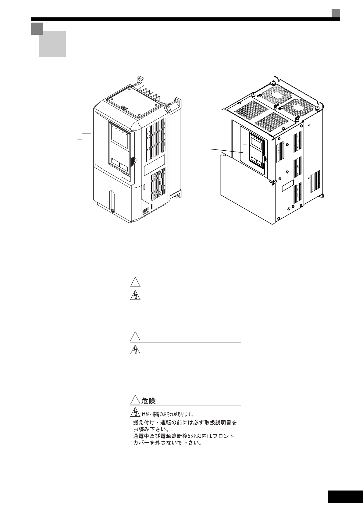
Warning Information and Position
There is warning information on the Inverter in the position shown in the following illustration.
Always heed the warnings.
Warning
information
position
Warning
information
position
Illustration shows the CIMR-G7A20P4
Warning Information
!
WARNING
Risk of electric shock.
yRead manual before installing.
yWait 5 minutes for capacitor discharge
after disconnecting power supply.
!
AVERTISSEMENT
Risque de décharge électrique.
yLire le manuel avant l' installation.
yAttendre 5 minutes aprés la coupure de
l' allmentation. Pour permettre la
décharge des condensateurs.
!
Illustration shows the CIMR-G7A2018
y
y
vii
Page 9

Warranty Information
Free Warranty Period and Scope
Warranty Period
This product is warranted for twelve months after being delivered to Yaskawa’s customer or if
applicable eighteen months from the date of shipment from Yaskawa’s factory whichever comes
first.
Scope of Warranty
Inspections
Periodic inspections must be conducted by the customer. However, upon request, Yaskawa or
one of Yaskawa’s Service Centers can inspect the product for a fee. In this case, if after conferring with the customer, a Yaskawa product is found to be defective due to Yaskawa workmanship or materials and the defect occurs during the warranty period, then this fee will be waived
and the problem remedied free of charge.
Repairs
If a Yaskawa product is found to be defective due to Yaskawa workmanship or materials and the
defect occurs during the warranty period, Yaskawa will provide a replacement, repair the defective product, and provide shipping to and from the site free of charge.
However, if the Yaskawa Authorized Service Center determines that the problem with a
Yaskawa product is not due to defects in Yaskawa’s workmanship or materials, then the customer will be responsible for the cost of any necessary repairs. Some problems that are outside
the scope of this warranty are:
• Problems due to improper maintenance or handling, carelessness, or other reasons where the
customer is determined to be responsible.
• Problems due to additions or modifications made to a Yaskawa product without Yaskawa’s
understanding.
• Problems due to the use of a Yaskawa product under conditions that do not meet the recom-
mended specifications.
• Problems caused by natural disaster or fire.
• Or other problems not due to defects in Yaskawa workmanship or materials.
Warranty service is only applicable within Japan.
However, after-sales service is available for customers outside of Japan for a reasonable fee.
Contact your local Yaskawa representative for more information.
Exceptions
Any inconvenience to the customer or damage to non-Yaskawa products due to Yaskawa's
defective products whether within or outside the warranty period are NOT covered by this warranty.
Restrictions
• The Varispeed G7 was not designed or manufactured for use in devices or systems that may
directly affect or threaten human lives or health.
• Customers who intend to use the product described in this manual for devices or systems
relating to transportation, health care, space aviation, atomic or electric power, or underwater
use must contact their Yaskawa representatives or the nearest Yaskawa sales office beforehand.
• This product has been manufactured under strict quality-control guidelines. However, if this
product is to be installed in any location where failure of this product could involve or result
in a life-and-death situation or loss of human life or in a facility where failure may cause a
serious accident or physical injury, safety devices must be installed to minimize the likelihood
of any accident.
viii
Page 10
Registered Trademarks
The following registered trademarks are used in this manual.
• DeviceNet is a registered trademark of the ODVA (Open DeviceNet Vendors Association,
Inc.).
• InterBus is a registered trademark of Phoenix Contact Co.
• ControlNet is a registered trademark of ControlNet International, Ltd.
• LONWORKS is a registered trademark of the Echelon.
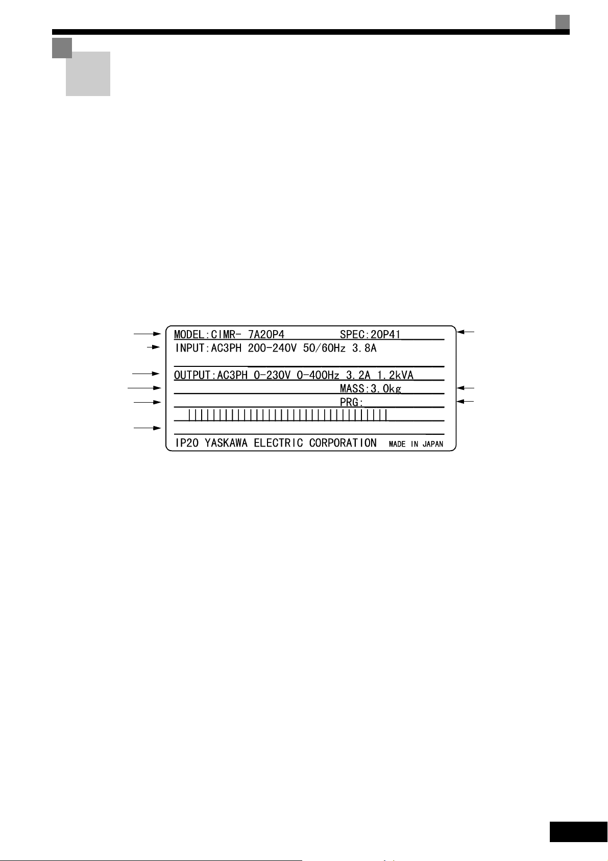
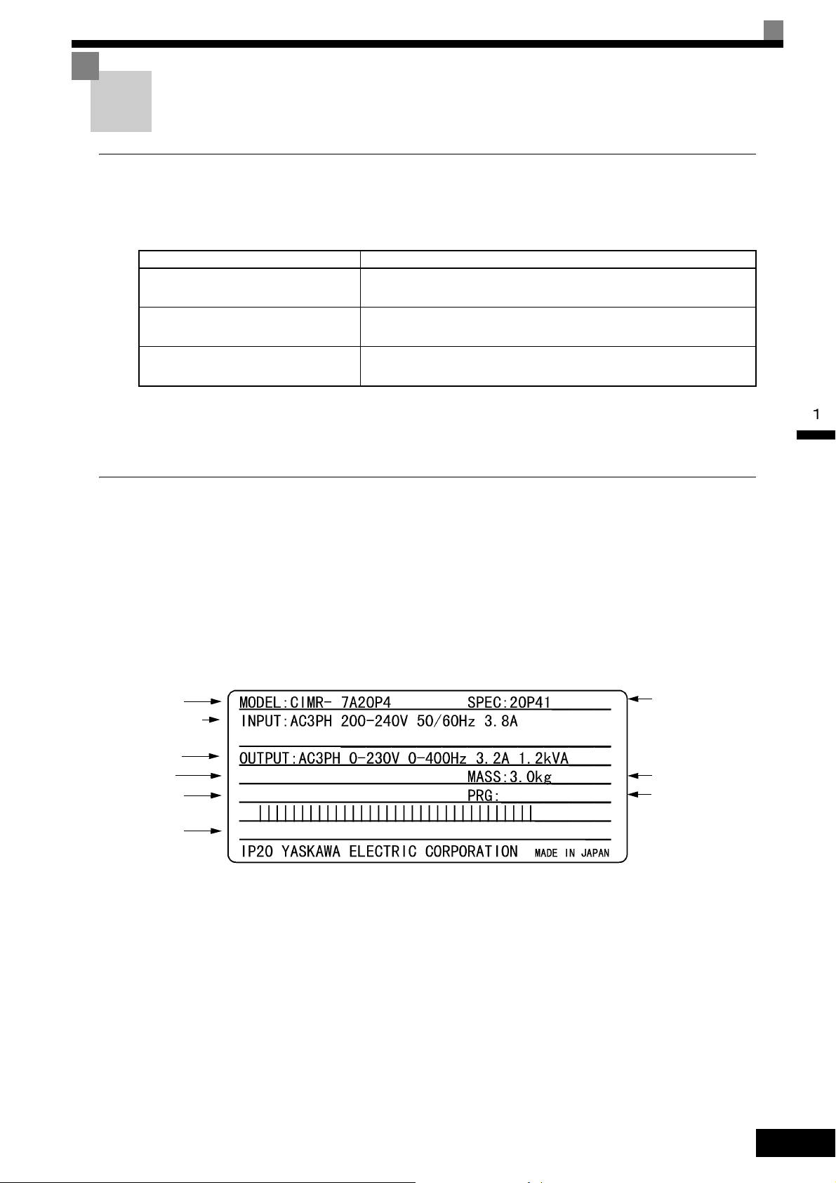
Before Reading This Manual
There are places in this manual where the constants and explanations depend on the software
version. Explanations for both old and new versions are provided. Parts that are shaded and
parts where “PRG: 102 only” appears apply to G7-series Inverters with software version
PRG: 102 and later. Parts where “PRG: 103 only” appears apply only to G7-series Inverters
with software version PRG: 103.
Be sure to confirm the PRG number on the Inverter’s nameplate. An example is given below.
Inverter model
Input specifications
Input specifications
Output
specifications
Lot number
Serial number
UL file number
G
O/N :
S/N :
FILE NO.: E131457
1020
Inverter
specifications
Mass
Version of software
ix
Page 11

Contents
Safety Information ............................................................................................ii
Safety Precautions ..........................................................................................iii
Warning Information and Position..................................................................vii
Warranty Information..................................................................................... viii
Registered Trademarks...................................................................................ix
Before Reading This Manual...........................................................................ix
1 Handling Inverters ...................................................................1-1
Varispeed G7 Introduction............................................................................ 1-2
Varispeed G7 Models..................................................................................................... 1-2
Confirmations upon Delivery........................................................................1-3
Checks ........................................................................................................................... 1-3
Nameplate Information................................................................................................... 1-3
Component Names ........................................................................................................ 1-5
Exterior and Mounting Dimensions ..............................................................1-6
Open Chassis Inverters (IP00) ....................................................................................... 1-6
Enclosed Wall-mounted Inverters [NEMA1 (Type 1)] ..................................................... 1-7
Checking and Controlling the Installation Site..............................................1-9
Installation Site...............................................................................................................1-9
Controlling the Ambient Temperature ............................................................................. 1-9
Protecting the Inverter from Foreign Matter ................................................................... 1-9
Installation Orientation and Space..............................................................1-10
Removing and Attaching the Terminal Cover ............................................. 1-11
Removing the Terminal Cover ...................................................................................... 1-11
Attaching the Terminal Cover ....................................................................................... 1-12
Removing/Attaching the Digital Operator and Front Cover ........................1-13
Inverters of 15 kW or Less ........................................................................................... 1-13
Inverters of 18.5 kW or More........................................................................................ 1-16
Removing and Attaching the Protection Cover .......................................... 1-17
Removing the Protection Cover ................................................................................... 1-17
Attaching the Protection Cover..................................................................................... 1-18
x
2 Wiring .......................................................................................2-1
Connections to Peripheral Devices.............................................................. 2-2
Connection Diagram .................................................................................... 2-3
Terminal Block Configuration ....................................................................... 2-5
Page 12

Wiring Main Circuit Terminals .......................................................................2-6
Applicable Wire Sizes and Closed-loop Connectors ......................................................2-6
Main Circuit Terminal Functions...................................................................................2-13
Main Circuit Configurations...........................................................................................2-14
Standard Connection Diagrams....................................................................................2-15
Wiring the Main Circuits................................................................................................2-16
Wiring Control Circuit Terminals .................................................................2-22
Wire Sizes and Closed-loop Connectors......................................................................2-22
Control Circuit Terminal Functions ...............................................................................2-24
Control Circuit Terminal Connections ...........................................................................2-28
Control Circuit Wiring Precautions................................................................................2-29
Wiring Check ..............................................................................................2-30
Checks..........................................................................................................................2-30
Installing and Wiring Option Boards ...........................................................2-31
Option Board Models and Specifications......................................................................2-31
Installation.....................................................................................................................2-32
PG Speed Control Board Terminals and Specifications................................................2-33
Wiring............................................................................................................................2-35
Wiring Terminal Blocks .................................................................................................2-38
Selecting the Number of PG (Encoder) Pulses ............................................................2-39
3 Digital Operator and Modes................................................... 3-1
Digital Operator ............................................................................................3-2
Digital Operator Display..................................................................................................3-2
Digital Operator Keys......................................................................................................3-2
Modes ...........................................................................................................3-5
Inverter Modes................................................................................................................3-5
Switching Modes.............................................................................................................3-6
Drive Mode .....................................................................................................................3-7
Quick Programming Mode ..............................................................................................3-8
Advanced Programming Mode .....................................................................................3-10
Verify Mode...................................................................................................................3-13
Autotuning Mode...........................................................................................................3-14
4 Trial Operation ........................................................................ 4-1
Overview of Trial Operation Procedure ........................................................4-2
Trial Operation Procedures...........................................................................4-3
Setting the Power Supply Voltage Jumper (400 V Class Inverters of 55 kW or Higher). 4-3
Power ON .......................................................................................................................4-3
Checking the Display Status...........................................................................................4-4
Basic Settings.................................................................................................................4-5
Settings for the Control Methods ....................................................................................4-7
Autotuning.......................................................................................................................4-9
Application Settings ......................................................................................................4-16
xi
Page 13

No-load Operation........................................................................................................ 4-16
Loaded Operation......................................................................................................... 4-16
Check and Recording User Constants ......................................................................... 4-17
Adjustment Suggestions ............................................................................ 4-18
5 User Constants ........................................................................5-1
User Constant Descriptions.......................................................................... 5-2
Description of User Constant Tables .............................................................................. 5-2
Digital Operation Display Functions and Levels........................................... 5-3
User Constants Settable in Quick Programming Mode.................................................. 5-4
User Constant Tables................................................................................... 5-8
A: Setup Settings............................................................................................................ 5-8
b: Application Constants............................................................................................... 5-10
C: Autotuning Constants .............................................................................................. 5-21
d: Reference Constants................................................................................................ 5-27
E: Motor Constant Constants ....................................................................................... 5-33
F: Option Constants ..................................................................................................... 5-39
H: Terminal Function Constants................................................................................... 5-46
L: Protection Function Constants ................................................................................. 5-58
N: Special Adjustments ................................................................................................ 5-69
o: Digital Operator Constants ....................................................................................... 5-73
T: Motor Autotuning...................................................................................................... 5-77
U: Monitor Constants.................................................................................................... 5-78
Factory Settings that Change with the Control Method (A1-02)................................... 5-87
Factory Settings that Change with the Inverter Capacity (o2-04)................................. 5-90
6 Constant Settings by Function...............................................6-1
Frequency Reference...................................................................................6-2
Selecting the Frequency Reference Source................................................................... 6-2
Using Multi-Step Speed Operation................................................................................. 6-5
Varispeed G7 Function Block......................................................................................... 6-8
Run Command ........................................................................................... 6-10
Selecting the Run Command Source ........................................................................... 6-10
Stopping Methods ...................................................................................... 6-12
Selecting the Stopping Method when a Stop Command is Sent .................................. 6-12
Using the DC Injection Brake ....................................................................................... 6-16
Using an Emergency Stop............................................................................................ 6-17
Acceleration and Deceleration Characteristics ..........................................6-18
Setting Acceleration and Deceleration Times............................................................... 6-18
Accelerating and Decelerating Heavy Loads (Dwell Function) .................................... 6-22
Preventing the Motor from Stalling During Acceleration
(Stall Prevention During Acceleration Function)........................................................... 6-23
Preventing Overvoltage During Deceleration
(Stall Prevention During Deceleration Function) ..........................................................6-25
xii
Page 14

Preventing Overvoltage by Automatically Reducing the Regenerative Torque Limit
(Overvoltage Inhibit Function, PRG: 102 only) ..........................................................6-26
Adjusting Frequency References ...............................................................6-28
Adjusting Analog Frequency References .....................................................................6-28
Operation Avoiding Resonance (Jump Frequency Function).......................................6-31
Adjusting Frequency Reference Using Pulse Train Inputs ...........................................6-33
Speed Limit (Frequency Reference Limit Function) ...................................6-34
Limiting Maximum Output Frequency...........................................................................6-34
Limiting Minimum Frequency........................................................................................6-34
Improved Operating Efficiency ...................................................................6-36
Reducing Motor Speed Fluctuation (Slip Compensation Function) ..............................6-36
Compensating for Insufficient Torque at Startup and Low-speed Operation
(Torque Compensation) ................................................................................................6-38
Hunting-prevention Function.........................................................................................6-40
Stabilizing Speed (Speed Feedback Detection Function) ............................................6-41
Machine Protection .....................................................................................6-42
Reducing Noise and Leakage Current..........................................................................6-42
Limiting Motor Torque (Torque Limit Function).............................................................6-46
Preventing Motor Stalling During Operation .................................................................6-49
Changing Stall Prevention Level during Operation Using an Analog Input ..................6-50
Using Frequency Detection: L4-01 to L4-05.................................................................6-50
Detecting Motor Torque ................................................................................................6-53
Changing Overtorque and Undertorque Detection Levels Using an Analog Input .......6-56
Motor Overload Protection............................................................................................6-57
Setting Motor Protection Operation Time......................................................................6-59
Motor Overheating Protection Using PTC Thermistor Inputs........................................6-60
Limiting Motor Rotation Direction..................................................................................6-62
Continuing Operation..................................................................................6-63
Restarting Automatically After Power Is Restored........................................................6-63
Speed Search ...............................................................................................................6-64
Continuing Operation at Constant Speed When Frequency Reference Is Lost............6-71
Restarting Operation After Transient Fault (Auto Restart Function).............................6-72
Operation Selection After Cooling Fan Fault ................................................................6-73
Inverter Protection ......................................................................................6-74
Performing Overheating Protection on Mounted Braking Resistors .............................6-74
Reducing Inverter Overheating Pre-Alarm Warning Levels..........................................6-75
Input Terminal Functions ............................................................................6-76
Temporarily Switching Operation between Digital Operator and
Control Circuit Terminals...............................................................................................6-76
Blocking Inverter Outputs (Baseblock Commands)......................................................6-77
Stopping Acceleration and Deceleration (Acceleration/Deceleration Ramp Hold) .......6-78
Raising and Lowering Frequency References Using Contact Signals (UP/DOWN).....6-79
Accelerating and Decelerating Constant Frequencies in the Analog References
(+/- Speed)....................................................................................................................6-82
Hold Analog Frequency Using User-set Timing............................................................6-83
xiii
Page 15

Switching Operations between a Communications Option Board and
Control Circuit Terminals .............................................................................................. 6-83
Jog Frequency Operation without Forward and Reverse Commands (FJOG/RJOG) . 6-84
Stopping the Inverter by Notifying Programming Device Errors to the Inverter
(External Fault Function) .............................................................................................. 6-85
Output Terminal Functions ......................................................................... 6-86
Monitor Constants ...................................................................................... 6-88
Using the Analog Monitor Constants............................................................................ 6-88
Using Pulse Train Monitor Contents............................................................................. 6-90
Individual Functions ................................................................................... 6-92
Using MEMOBUS Communications............................................................................. 6-92
Using the Timer Function ........................................................................................... 6-105
Using PID Control....................................................................................................... 6-106
Energy-saving ............................................................................................................ 6-115
Setting Motor Constants............................................................................................. 6-117
Setting the V/f Pattern ................................................................................................6-120
Torque Control ........................................................................................................... 6-127
Speed Control (ASR) Structure .................................................................................. 6-136
Increasing the Speed Reference Response (Feed Forward Control) ........................ 6-142
Droop Control Function .............................................................................................. 6-143
Zero-servo Function ................................................................................................... 6-145
Digital Operator Functions........................................................................ 6-148
Setting Digital Operator Functions ............................................................................. 6-148
Copying Constants..................................................................................................... 6-151
Prohibiting Writing Constants from the Digital Operator.............................................6-156
Setting a Password .................................................................................................... 6-156
Displaying User-set Constants Only........................................................................... 6-157
Options ..................................................................................................... 6-158
Performing Speed Control with PG ............................................................................ 6-158
Using Digital Output Boards ....................................................................................... 6-162
Using an Analog Reference Board............................................................................. 6-164
Using a Digital Reference Board ................................................................................ 6-165
Using Inverters for Elevating Machines.................................................... 6-170
Brake ON/OFF Sequence .......................................................................................... 6-170
Stall Prevention during Deceleration .......................................................................... 6-172
Autotuning .................................................................................................................. 6-172
Braking Resistor Overheating Protection ................................................................... 6-172
Momentary Power Loss Restart ................................................................................. 6-172
Torque Limit................................................................................................................ 6-172
I/O Open-phase Protection and Overtorque Detection .............................................. 6-173
External Baseblock Signal.......................................................................................... 6-173
Acceleration/Deceleration Time.................................................................................. 6-173
Magnetic Contactor on the Inverter’s Output-side...................................................... 6-173
Control-related Adjustments....................................................................................... 6-174
xiv
Page 16

Reducing Shock during Elevating Machine Start, Stop, Acceleration,
and Deceleration.........................................................................................................6-176
Confirming Startup Current and Reducing Carrier Frequency....................................6-179
Overvoltage Inhibit Function.......................................................................................6-180
Current Alarm Function ............................................................................6-181
Peak Hold Current Monitoring Function ...................................................6-182
Maintenance Timer Display Function .......................................................6-183
Settings Required to Use Maintenance Timer Display Function.................................6-183
Settings Required After Replacement of Cooling Fan or Electrolytic Capacitor .........6-184
7 Troubleshooting ..................................................................... 7-1
Protective and Diagnostic Functions ............................................................7-2
Fault Detection................................................................................................................7-2
Alarm Detection ............................................................................................................7-15
Operation Errors ...........................................................................................................7-20
Errors During Autotuning .............................................................................................7-22
Errors when Using the Digital Operator Copy Function................................................7-23
Troubleshooting ..........................................................................................7-25
If Constant Constants Cannot Be Set...........................................................................7-25
If the Motor Does Not Operate......................................................................................7-26
If the Direction of the Motor Rotation is Reversed........................................................7-29
If the Motor Does Not Put Out Torque or If Acceleration is Slow..................................7-29
If the Motor Operates Higher Than the Reference .......................................................7-29
If the Slip Compensation Function Has Low Speed Precision......................................7-30
If There is Low Speed Control Accuracy at High-speed Rotation in
Open-loop Vector Control Method................................................................................7-30
If Motor Deceleration is Slow ........................................................................................7-30
If the Motor Overheats..................................................................................................7-31
If There is Noise When the Inverter is Started or From an AM Radio ..........................7-32
If the Ground Fault Interrupter Operates When the Inverter is Run..............................7-32
If There is Mechanical Oscillation.................................................................................7-32
If the Torque Generated for the Motor is Insufficient (Insufficient Power).....................7-34
If the Torque Reference (U1-09) at Low Speeds in Open-loop Vector 2 Control is
Large Compared to That at Medium and High Speeds ................................................7-34
If Shock Occurs Near the Speed Estimator Switching Frequency in
Open-loop Vector 2 Control (PRG: 102 only) ............................................................7-34
If Torque Ripple Occurs at Very Low Speeds in Open-loop Vector 2 Control
(PRG: 102 only).........................................................................................................7-35
If the Motor Rotates Even When Inverter Output is Stopped........................................7-35
If OV is Detected When the Fan is Started, or Fan Stalls .............................................7-35
If Output Frequency Does Not Rise to Frequency Reference ......................................7-35
Acoustic Noise From the Motor ....................................................................................7-36
xv
Page 17

8 Maintenance and Inspection ..................................................8-1
Maintenance and Inspection ........................................................................8-2
Outline of Warranty......................................................................................................... 8-2
Daily Inspection.............................................................................................................. 8-2
Periodic Inspection......................................................................................................... 8-2
Periodic Maintenance of Parts ....................................................................................... 8-3
Procedure for Adjusting Constants after Replacement of Control Board ....................... 8-3
Types and Number of Cooling Fans Used in the Drive ..................................................8-5
Cooling Fan Replacement Outline ................................................................................. 8-6
Circulation Fan Replacement Outline........................................................................... 8-16
Removing and Mounting the Control Circuit Terminal Board ....................................... 8-21
9 Specifications ..........................................................................9-1
Standard Inverter Specifications................................................................... 9-2
Specifications by Model.................................................................................................. 9-2
Common Specifications.................................................................................................. 9-4
Specifications of Options and Peripheral Devices........................................ 9-6
10 Appendix ................................................................................10-1
Varispeed G7 Control Methods .................................................................. 10-2
Control Methods and Features..................................................................................... 10-2
Control Methods and Applications................................................................................ 10-4
Inverter Application Precautions ................................................................ 10-6
Selection.......................................................................................................................10-6
Installation ....................................................................................................................10-7
Settings ........................................................................................................................10-7
Handling .......................................................................................................................10-8
Motor Application Precautions ................................................................... 10-9
Using the Inverter for an Existing Standard Motor........................................................ 10-9
Using the Inverter for Special Motors ......................................................................... 10-10
Power Transmission Mechanism (Speed Reducers, Belts, and Chains) ................... 10-10
Conformance to UL Standard................................................................... 10-11
Conformance to CE Markings .................................................................. 10-13
CE Markings............................................................................................................... 10-13
Requirements for Conformance to CE Markings........................................................ 10-13
xvi
Wiring Examples ...................................................................................... 10-20
Using a Braking Resistor Unit .................................................................................... 10-20
Using a Braking Unit and Braking Resistor Unit......................................................... 10-21
Using Braking Units in Parallel ................................................................................... 10-22
Using a Braking Unit and Three Braking Resistor Units in Parallel............................ 10-23
Using a VS Operator .................................................................................................. 10-24
Using Transistors for Input Signals and a 0-V Common in Sinking Mode with an
Internal Power Supply ................................................................................................ 10-25
Page 18

Using Transistors for Input Signals and a +24-V Common in Sourcing Mode............10-26
Using Transistors for Input Signals and a 0-V Common in Sinking Mode with an
External Power Supply ...............................................................................................10-27
Using Contact and Open Collector Outputs................................................................10-28
User Constants.........................................................................................10-29
INDEX
Revision History
xvii
Page 19

1
Handling Inverters
This chapter describes the checks required upon receiving or installing an Inverter.
Varispeed G7 Introduction ...........................................1-2
Confirmations upon Delivery........................................1-3
Exterior and Mounting Dimensions..............................1-6
Checking and Controlling the Installation Site .............1-9
Installation Orientation and Space .............................1-10
Removing and Attaching the Terminal Cover ............ 1-11
Removing/Attaching the Digital Operator and Front
Cover .........................................................................1-13
Removing and Attaching the Protection Cover.......... 1-17
Page 20

Varispeed G7 Introduction
Varispeed G7 Models
The Varispeed-G7 Series of Inverters included two Inverters in two voltage classes: 200 V and 400 V. Maximum
motor capacities vary from 0.4 to 300 kW (41 models).
Table 1.1 Varispeed G7 Models
Voltage
Class
200 V Class
400 V Class
Maximum
Motor
Capacity
kW
0.4 1.2 CIMR-G7A20P4
0.75 2.3 CIMR-G7A20P7 20P71
1.5 3.0 CIMR-G7A21P5 21P51
2.2 4.6 CIMR-G7A22P2 22P21
3.7 6.9 CIMR-G7A23P7 23P71
5.5 10 CIMR-G7A25P5 25P51
7.5 13 CIMR-G7A27P5 27P51
11 19 CIMR-G7A2011 2011
15 25 CIMR-G7A2015 20151
18.5 30 CIMR-G7A2018 20180 20181
22 37 CIMR-G7A2022 20220 20221
30 50 CIMR-G7A2030 20300 20301
37 61 CIMR-G7A2037 20370 20371
45 70 CIMR-G7A2045 20450 20451
55 85 CIMR-G7A2055 20550 20551
75 110 CIMR-G7A2075 20750 20751
90 140 CIMR-G7A2090 20900 -
110 160 CIMR-G7A2110 21100 -
0.4 1.4 CIMR-G7A40P4
0.75 2.6 CIMR-G7A40P7 40P71
1.5 3.7 CIMR-G7A41P5 41P51
2.2 4.7 CIMR-G7A42P2 42P21
3.7 6.9 CIMR-G7A43P7 43P71
5.5 11 CIMR-G7A45P5 45P51
7.5 16 CIMR-G7A47P5 47P51
11 21 CIMR-G7A4011 40111
15 26 CIMR-G7A4015 40151
18.5 32 CIMR-G7A4018 40180 40181
22 40 CIMR-G7A4022 40220 40221
30 50 CIMR-G7A4030 40300 40301
37 61 CIMR-G7A4037 40370 40371
45 74 CIMR-G7A4045 40450 40451
55 98 CIMR-G7A4055 40550 40551
75 130 CIMR-G7A4075 40750 40751
90 150 CIMR-G7A4090 40900 40901
110 180 CIMR-G7A4110 41100 41101
132 210 CIMR-G7A4132 41320 41321
160 250 CIMR-G7A4160 41600 41601
185 280 CIMR-G7A4185 41850 -
220 340 CIMR-G7A4220 42200 -
300 460 CIMR-G7A4300 43000 -
Output
Capacity
kVA
Va r i sp ee d G7
Basic Model Number
(Always specify through the protective structure when ordering.)
Open Chassis
(IEC IP00)
CIMR-G7
Remove the top and bottom cov-
ers from the Enclosed Wall-
mounted model.
Remove the top and bottom cov-
ers from the Enclosed Wall-
mount model.
Specifications
Enclosed Wall-mounted
[IEC IP20, NEMA 1 (Type 1)]
CIMR-G7A
20P41
40P41
1-2
Page 21
Confirmations upon Delivery
Checks
Check the following items as soon as the Inverter is delivered.
Table 1.2 Checks
Item Method
Has the correct model of Inverter been
delivered?
Check the model number on the nameplate on the side of the Inverter.
Confirmations upon Delivery
Is the Inverter damaged in any way?
Are any screws or other components
loose?
Inspect the entire exterior of the Inverter to see if there are any scratches or
other damage resulting from shipping.
Use a screwdriver or other tools to check for tightness.
If you find any irregularities in the above items, contact the agency from which you purchased the Inverter or
your Yaskawa representative immediately.
Nameplate Information
There is a nameplate attached to the side of each Inverter. The nameplate shows the model number, specifications, lot number, serial number, and other information on the Inverter.
Example Nameplate
The following nameplate is an example for a standard domestic (Japan) Inverter: 3-phase, 200 VAC, 0.4 kW,
IEC IP20 and NEMA 1 (Type 1) standards
Inverter model
Input specifications
Input specifications
Output
specifications
Lot number
Serial number
O/N :
S/N :
G
1020
Inverter
specifications
Mass
Version of software
UL file number
FILE NO.: E131457
Fig 1.1 Nameplate
1-3
Page 22

Inverter Model Numbers
The model number of the Inverter on the nameplate indicates the specification, voltage class, and maximum
motor capacity of the Inverter in alphanumeric codes.
CIMR - G7 A 2 0P4
Inverter
Varispeed G7
No.
A
No.
2
4
Specification
Standard domestic model
Voltage Class
AC input, 3-phase, 200 V
AC input, 3-phase, 400 V
Fig 1.2 Inverter Model Numbers
No.
Max. Motor Capacity
0P4
0P7
to
300
"P" indicates the decimal point.
0.4 kW
0.75 kW
to
300 kW
*
Inverter Specifications
The Inverter specifications (“SPEC”) on the nameplate indicate the voltage class, maximum motor capacity,
the protective structure, and the revision of the Inverter in alphanumeric codes.
2 0P4 1 A
No.
2
4
Voltage Class
AC input, 3-phase, 200 V
AC input, 3-phase, 400 V
Design revision order
TERMS
No.
0P4
0P7
300
"P" indicates the decimal point.
Max. Motor Capacity
to
0.4 kW
0.75 kW
to
300 kW
*
No.
0
1
Protective Structure
Open chassis (IEC IP00)
Enclosed wall-mounted [IEC IP20,
NEMA 1 (Type 1)]
Fig 1.3 Inverter Specifications
Open Chassis Type (IEC IP00)
Protected so that parts of the human body cannot reach electrically charged parts from the front when the
Inverter is mounted in a control panel.
Enclosed Wall-mounted Type [IEC IP20, NEMA 1 (Type 1)]
The Inverter is structured so that the Inverter is shielded from the exterior, and can thus be mounted to the
interior wall of a standard building (not necessarily enclosed in a control panel). The protective structure conforms to the standards of NEMA 1 (Type 1) in the USA. The protective covers (see Fig. 1.4) are required for
an IEC IP20 or NEMA 1 (Type 1) protective structure.
1-4
Page 23
Confirmations upon Delivery
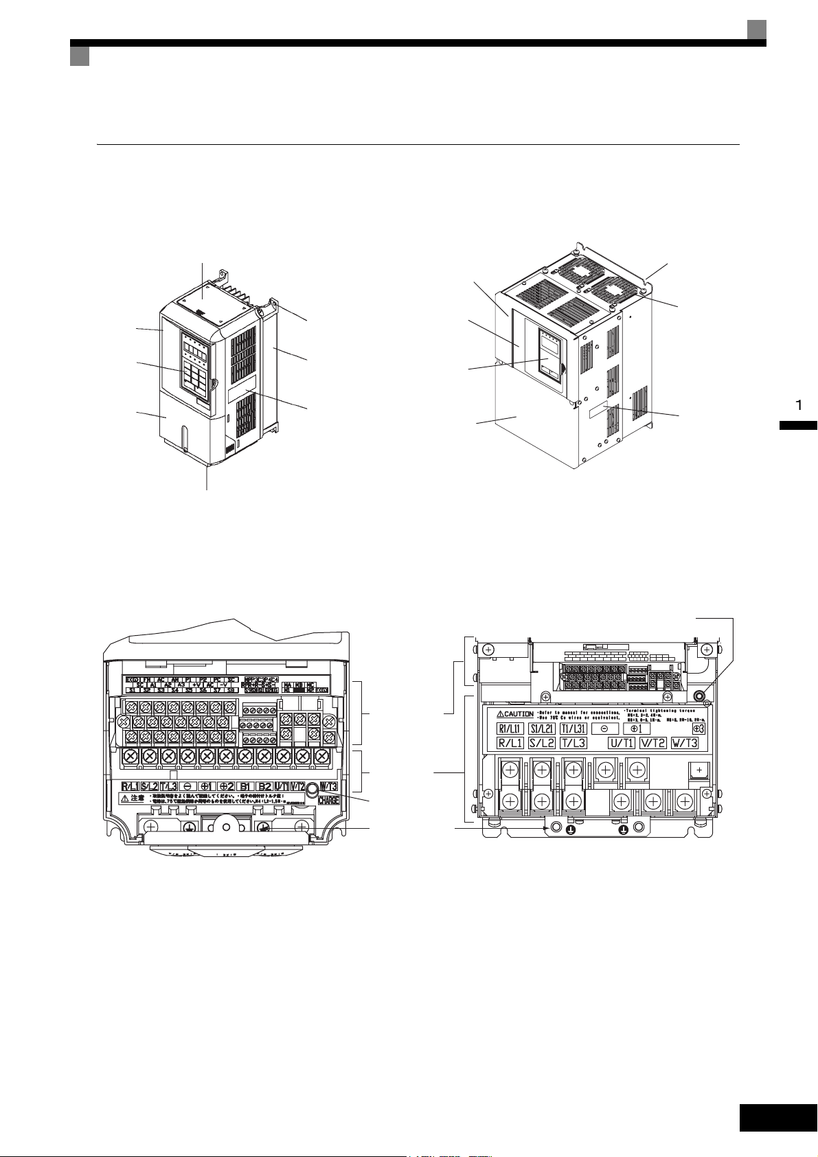
Component Names
The external appearance and component names of the Inverter are shown in Fig 1.4. The Inverter with the terminal cover removed is shown in Fig 1.5.
Front
cover
Digital
Operator
Terminal
cover
Top protective cover
Inverter cover
Mounting hole
Diecast case
Nameplate
Bottom protective cover
15 kW or Less 18.5 kW or More
Front cover
Digital
Operator
Terminal
cover
Fig 1.4 Inverter Appearance
Mounting
hole
Cooling
fan
Nameplate
Charge indicator
15 kW or Less
Control circuit
terminals
Main circuit
terminals
Charge indicator
Ground terminal
18.5 kW or More
Fig 1.5 Terminal Arrangement
1-5
Page 24

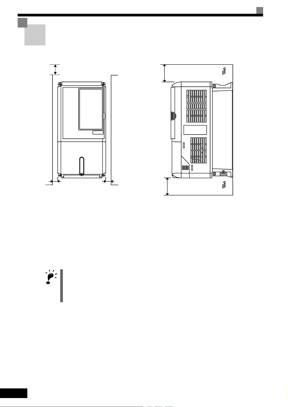
Exterior and Mounting Dimensions
Open Chassis Inverters (IP00)
Exterior diagrams of the Open Chassis Inverters are shown below.
W1
W
200 V/400 V Class Inverters of 0.4 to 15 kW
4-d
H1H2DH
3
W2
D1
W1
6-d
W1
t1
(5)*
* (10) for 200 V Class Inverters of 30 to 110 kW or
400 V Class Inverters of 55 to 160 kW.
200 V Class Inverters of 18.5 to 110 kW
400 V Class Inverters of 18.5 to 160 kW
W
4-d
(5)*
H1
H2
H
t1
(5)
D1
D
1-6
H
W3
W1
W
400 V Class Inverters of 185 to 300 kW
H2 H1
D
Fig 1.6 Exterior Diagrams of Open Chassis Inverters
t1
D1
Page 25

Exterior and Mounting Dimensions
Enclosed Wall-mounted Inverters [NEMA1 (Type 1)]
Exterior diagrams of the Enclosed Wall-mounted Inverters [NEMA1 (Type 1)] are shown below.
W1
W
200 V/400 V Class Inverters of 0.4 to 15 kW
4-d
H1H2DH0
H3
4 H
3
Fig 1.7 Exterior Diagrams of Enclosed Wall-mounted Inverters
D1
W1
t1
W
* (7.5) for 200 V Class Inverters of 30 to 75 kW or 400 V
Class Inverters of 55 to 160 kW.
200 V Class Inverters of 18.5 to 75 kW
400 V Class Inverters of 18.5 to 160 kW
4-d
H1
H2
(5)*(5)*
Grommet
H0
H3
H
Max.10
t1
D1
D(5)
1-7
Page 26
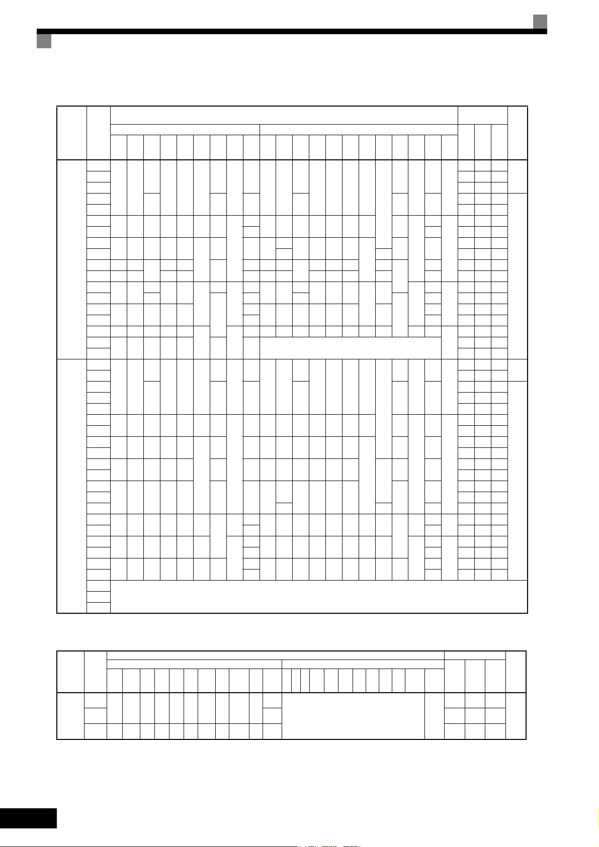
Table 1.3 200 VAC and 400 VAC (0.4 kW to 300 kW) Inverter Dimensions (mm) and Masses (kg)
Max.
Appli-
Voltage
cable
Class
Motor
Output
W H D W1H1H2D1 t1
[kW]
0.4
0.75 43 42 85
140 280
1.5 58 47 105
2.2
3.7 122 64 186
5.5
200 300 197 186 285 8 65.5
7.5 7 7 263 112 375
11
240 350 207 216 335
200 V
(3-phase)
15 380 30 473 174 647
18.5 250 400
22 275 450 220 435 24 279 615 220 450 435 165 27 679 257 936
30
375 600
37 328
45
450 725 348 325 700
55 87 95 1474 607 2081
75 500 850 358 370 820
90
575 885 378 445 855 140 150 ---
110 2389 1194 3583
0.4
0.75 21 44 65
1.5
140 280
2.2 41 49 90
3.7 76 64 140
5.5
200 300 197 186 285 8 65.5
7.5 198 106 304
11
240 350 207 216 335
15 311 135 446
18.5
275 450 258 220 435 100 26 279 535 258 220 450 435
400 V
(3-phase)
22 516 210 726
30
325 550 283 260 535 105 37 329
37 737 285 1022
45 715 165 40 929 340 1269
55
450 725 348 325 700 12.5
75 91 99 1554 596 2150
90
500 850 358 370 820 15
110 127 137 2299 928 3227
132
575 916 378 445 855 46 140
160 175 185 3614 1501 5115
185
300
* Same for Open Chassis and Enclosed Wall-mounted Inverters.
Open Chassis (IP00) Enclosed Wall-mounted [NEMA1 (Type 1)]
157
126 266 7
39
5
177 59 4 177 59 4
78 11 240
2.3
7.5
12.5
100
100
3.2
258
298
195 385
250 575
130
15 4.5
157
126 266 7
39
5
177 59 4.5 177 59 4.5
78 10 240 350 207 216 350 335
2.3
7.5
3.2
130
4.5
Dimensions (mm)
Approx.
W H D W1H0H1H2H3D1 t1
Mass
3
140 280
157
126 280 266 7
Approx.
Mass
39
5
0
6
200 300 197 186 300 285 8 65.5
350
207 216 350 335
21 254 535
57
380 809
63 328
86
453 1027 348 325 725 700 302
195 400 385 135
258
298
250 600 575
7.5
12.5
209
78 11
2.3
100
3.2
130
108 504 1243 358 370 850 820 15 393 4.5 114
3.5
140 280
157
126 280 266 7
39
5
0
7 200 300 197 186 300 285 8 65.5
78 10
2.3
7.5
635
283 260 550 535 105
90
453 1027 348 325 725 700 12.5 302
109
504 1243 358 370 850 820 15 393
165
579 1324 378 445 916 855 46 408 140
100 29
85
130
3.2
127
4.5
175 2612 1105 3717
See Table 1.4220
Heat Genera-
tion (W)
Tot a l
Mount-
ing
Holes
d*
Exter
nal
Inter-
nal
Heat
Gen-
eration
21 36 57
3
M5
83 53 136
6
187 87 274
357 136 493
M6
24 599 242 839
62
68 1080 434 1514
94 1291 510 1801
878 362 1240
M10
2009 823 2832
M12
1660 871 2531
3.5
7
10 39 49
M5
33 46 79
132 79 211
246 116 362
354 174 528
M6
39
98
633 246 879
1239 488 1727
M10
1928 762 2690
M12
Cooling
Method
Natu-
ral
Fan
Natu-
ral
Fan
1-8
Voltage
Class
400 V
(3-phase)
Table 1.4 400 VAC (185 to 300 kW) Inverter Dimensions (mm) and Masses (kg)
Max.
Appli-
cable
Motor
W H D W1W2W3 H1 H2 D1 t1
Output
[kW]
185
710 1305 413 540 240 270 1270 15 125.5 4.5
300 916 1475 413 730 365 365 1440 15 125.5 4.5 415 6749 2941 9690
Open Chassis (IP00) Enclosed Wall-mounted [NEMA (Type1)]
Dimensions (mm) Heat Generation (W )
Mount-
Exter-
Approx.
WHDW1W2W3H1H2D1 t1
Mass
260
--- M12
Approx.
Mass
ing
Holes
d*
Inter-
nal
nal
4436 1994 6430
Tot a l
Heat
Gener-
ation
Cooling
Method
Fan220 280 5329 2205 7534
Page 27

Checking and Controlling the Installation Site
Checking and Controlling the Installation Site
Install the Inverter in the installation site described below and maintain optimum conditions.
Installation Site
Install the Inverter under the following conditions and a pollution level of 2 or less (UL standard).
Table 1.5 Installation Site
Type Ambient Operating Temperature Humidity
Enclosed wall-mounted -10 to + 40 °C 95% RH or less (no condensation)
Open chassis -10 to + 45 °C 95% RH or less (no condensation)
Protection covers are attached to the top and bottom of the Inverter. Be sure to remove the protection covers
before installing a 200 or 400 V Class Inverter with an output of 15 kW or less in a panel. Refer to Page 1-17
on how to remove the protection covers.
Observe the following precautions when mounting the Inverter.
• Install the Inverter in a clean location free from oil mist and dust. It can be installed in a totally enclosed
panel that is completely shielded from floating dust.
• When installing or operating the Inverter, always take special care so that metal powder, oil, water, or other
foreign matter does not get into the Inverter.
• Do not install the Inverter on combustible material, such as wood.
• Install the Inverter in a location free from radioactive materials and combustible materials.
• Install the Inverter in a location free from harmful gasses and liquids.
• Install the Inverter in a location without excessive oscillation.
• Install the Inverter in a location free from chlorides.
• Install the Inverter in a location not in direct sunlight.
Controlling the Ambient Temperature
To enhance the reliability of operation, the Inverter should be installed in an environment free from extreme
temperature increases. If the Inverter is installed in an enclosed environment, such as a box, use a cooling fan
or air conditioner to maintain the internal air temperature below 45°C.
Protecting the Inverter from Foreign Matter
Place a cover over the Inverter during installation to shield it from metal powder produced by drilling.
Always remove the cover from the Inverter after completing installation. Otherwise, ventilation will be
reduced, causing the Inverter to overheat.
1-9
Page 28
Installation Orientation and Space
Install the Inverter vertically so as not to reduce the cooling effect. When installing the Inverter, always
provide the following installation space to allow normal heat dissipation.
A mm min.
30 mm min.
30 mm min.
B mm min.
Air
120 mm min.
Air
Vertical SpaceHorizontal Space
200 V Class Inverters of 110 kW or 400 V Class Inverters of 160 to 220 kW*: A = 120, B = 120
400 V Class Inverters of 300 kW*: A = 300, B = 300
All other Inverters*: A = 50, B = 120
*If, however, there is a fan in the top of the control panel with sufficient exhaust capacity, the following
dimensions may be used: A = 50, B = 120.
Fig 1.8 Inverter Installation Orientation and Space
1. The same space is required horizontally and vertically for both Open Chassis (IP00) and Enclosed Wallmounted [IP20, NEMA 1 (Type 1)] Inverters.
IMPORTANT
2. Always remove the protection covers before installing a 200 or 400 V Class Inverter with an output of
15 kW or less in a panel. Refer to Page 1-17 on how to remove the protection covers.
Always provide enough space for suspension eye bolts and the main circuit lines when installing a 200 or
400 V Class Inverter with an output of 18.5 kW or more in a panel.
1-10
Page 29

Removing and Attaching the Terminal Cover
Removing and Attaching the Terminal Cover
Remove the terminal cover to wire cables to the control circuit and main circuit terminals.
Removing the Terminal Cover
Inverters of 15 kW or Less
Loosen the screws at the bottom of the terminal cover, press in on the sides of the terminal cover in the direction indicated by arrow 1, and then lift the terminal cover up to an angle of about 30 degrees in the direction
indicated by arrow 2.
Remove the terminal cover in the direction indicated by arrow 3.
1
2
1
3
Fig 1.9 Removing the Terminal Cover (Model CIMR-G7A23P7 Shown Above)
Approx. 30
°
Inverters of 18.5 kW or More
Loosen the screws on the left and right at the top of the terminal cover, pull out the terminal cover in the direction of arrow 1 and then lift up on the terminal in the direction of arrow 2.
1
2
Fig 1.10 Removing the Terminal Cover (Model CIMR-G7A2018 Shown Above)
1-11
Page 30

Attaching the Terminal Cover
When wiring the terminal block has been completed, attach the terminal cover by reversing the removal procedure.
For Inverters with an output of 15 kW or less, insert the tab on the top of the terminal cover into the grove on
the Inverter and press in on the bottom of the terminal cover until it clicks into place.
1-12
Page 31

Removing/Attaching the Digital Operator and Front Cover
Removing/Attaching the Digital Operator and
Front Cover
The methods of removing and attaching the Digital Operator and Front Cover are described in this section.
Inverters of 15 kW or Less
To attach optional boards or change the terminal board connector, remove the Digital Operator and front cover
in addition to the terminal cover. Always remove the Digital Operator from the front cover before removing
the terminal cover.
The removal and attachment procedures are given below.
Removing the Digital Operator
Press the lever on the side of the Digital Operator in the direction of arrow 1 to unlock the Digital Operator
and lift the Digital Operator in the direction of arrow 2 to remove the Digital Operator as shown in the following illustration.
2
Fig 1.11 Removing the Digital Operator (Model CIMR-G7A43P7 Shown Above)
1
1-13
Page 32

Removing the Front Cover
Press the left and right sides of the front cover in the directions of arrows 1 and lift the bottom of the cover in
the direction of arrow 2 to remove the front cover as shown in the following illustration.
1
1
2
Fig 1.12 Removing the Front Cover (Model CIMR-G7A43P7 Shown Above)
Mounting the Front Cover
After wiring the terminals, mount the front cover to the Inverter by performing in reverse order to the steps to
remove the front cover.
1. Do not mount the front cover with the Digital Operator attached to the front cover; otherwise, Digital
Operator may malfunction due to imperfect contact.
2. Insert the tab of the upper part of the front cover into the groove of the Inverter and press the lower part of
the front cover onto the Inverter until the front cover snaps shut.
Mounting the Digital Operator
After attaching the front cover, mount the Digital Operator onto the Inverting using the following procedure.
1. Hook the Digital Operator at A (two locations) on the front cover in the direction of arrow 1 as shown in
the following illustration.
2. Press the Digital Operator in the direction of arrow 2 until it snaps in place at B (two locations).
1-14
Page 33

Removing/Attaching the Digital Operator and Front Cover
A
1
2
B
Fig 1.13 Mounting the Digital Operator
IMPORTANT
1. Do not remove or attach the Digital Operator or mount or remove the front cover using methods other than
those described above, otherwise the Inverter may break or malfunction due to imperfect contact.
2. Never attach the front cover to the Inverter with the Digital Operator attached to the front cover. Imperfect
contact can result.
Always attach the front cover to the Inverter by itself first, and then attach the Digital Operator to the front
cover.
1-15
Page 34

Inverters of 18.5 kW or More
For Inverter with an output of 18.5 kW or more, remove the terminal cover and then use the following procedures to remove the Digital Operator and front cover.
Removing the Digital Operator
Use the same procedure as for Inverters with an output of 18.5 kW or less.
Removing the Front Cover
Lift up at the location label 1 at the top of the control circuit terminal board in the direction of arrow 2.
2
1
Fig 1.14 Removing the Front Cover (Model CIMR-G7A2018 Shown Above)
Attaching the Front Cover
After completing required work, such as mounting an optional board or setting the control circuit terminal
board, attach the front cover by reversing the procedure to remove it.
1. Confirm that the Digital Operator is not mounted on the front cover. Contact faults can occur if the cover is
attached while the Digital Operator is mounted to it.
2. Insert the tab on the top of the front cover into the slot on the Inverter and press in on the cover until it
clicks into place on the Inverter.
Attaching the Digital Operator
Use the same procedure as for Inverters with an output of 15 kW or less.
1-16
Page 35

Removing and Attaching the Protection Cover
Removing and Attaching the Protection Cover
Inverters of 15 kW or less have protection covers on the top and bottom as shown in Fig. 1.4.Always
remove the protection covers before installing an Inverter of 15 kW or less in a panel. Use the following
procedure to remove and attach a protection cover.
Removing the Protection Cover
Top Protection Cover
Insert the tip of the straightedge screwdriver in the slot. Then, lift the cover up in the direction shown by the
arrow to remove it.
Slot
Fig 1.15 Removing the Top Protection Cover (Model CIMR-G7A43P7 Shown Above)
Bottom Protection Cover
1. Remove the terminal cover as described on Page 1-11.
2. Loosen the two screws, and remove the protection cover.
3. Return the screws to their original position and tighten (them).
4. Reattach the terminal cover as described on Page 1-12.
Screws
Bottom Protection
Cover
Terminal Cover
Fig 1.16 Removing the Bottom Protection Cover (Model CIMR-G7A43P7 Shown Above)
1-17
Page 36

Attaching the Protection Cover
Top Protection Cover
The protection cover has four hooks: two hooks on the bottom and two on the sides. Fit the bottom hooks into
the holes, bend the cover slightly, and press the cover down until the hooks on the side snap.
Holes for bottom hooks
Fig 1.17 Attaching the Top Protection Cover (Model CIMR-G7A43P7 Shown Above)
Bottom Protection Cover
To attach the bottom protection cover, reverse the procedure used to remove it.
1-18
Page 37

2
Wiring
This chapter describes wiring terminals, main circuit terminal connections, main circuit termi-
nal wiring specifications, control circuit terminals, and control circuit wiring specifications.
Connections to Peripheral Devices..............................2-2
Connection Diagram ....................................................2-3
Terminal Block Configuration.......................................2-5
Wiring Main Circuit Terminals ......................................2-6
Wiring Control Circuit Terminals ................................2-22
Wiring Check .............................................................2-30
Installing and Wiring Option Boards ..........................2-31
Page 38

Connections to Peripheral Devices
Examples of connections between the Inverter and typical peripheral devices are shown in Fig 2.1.
Power supply
Molded-case
circuit breaker
or ground fault
interrupter
Magnetic contactor (MC)
AC reactor for power
factor improvement
Zero phase reactor
Input noise filter
Inverter
Ground
Output noise filter
Braking resistor
Varispeed F7
DC reactor for power
factor improvement
Zero phase reactor
2-2
Motor
Ground
Fig 2.1 Example Connections to Peripheral Devices
Page 39

Connection Diagram
00
)
+1
+ 3
3
C
S
S
The connection diagram of the Inverter is shown in Fig 2.2.
When using the Digital Operator, the motor can be operated by wiring only the main circuits.
3-phase power
to 240 V
2
50/60 Hz
2MCCB
1MCCB
R
MC
S
T
FU
FV
FW
R/L1
S/L2
T/L3
Thermal switch contact
Braking Unit
(optional)
Inverter
CIMR-G7A2018
+
Level
detector
-
-
U/T1
V/T2
W/T3
Thermal relay
trip contact
43 21
+
0
-
0
Braking Resistor Unit
(optional)
Connection Diagram
P
B
FU
FV
FW
Motor
Cooling fan
IM
U
V
IM
2MCCB THRX OFF
Thermal relay trip contact
for Braking Resistor Unit
Thermal relay trip contact
for motor cooling fan
21
MC
MC
External
frequency
references
ON
MC
21
MA
Multi-function
contact inputs
MC
A
SA
TRX
A
TRX
Fault contact
Factory
settings
Pulse train input
Frequency
setter
2k
Ω
Forward Run/Stop
Reverse Run/Stop
Thermal switch contact
for Braking Unit
External fault
Fault reset
Multi-step speed reference 1
(Main speed switching)
Multi-step speed
reference 2
Jog frequency
selection
External
baseblock command
Multi-step speed
reference 3
Multi-step speed
reference 4
Acc/dec time 1
Emergency stop (NO)
Frequency setting
adjustment
2k
Ω
0 to 10 V
4 to 20 mA
0 to 10 V
MEMOBUS
communications
RS-485/422
34
P
S1
S2
S3
S4
S5
S6
S7
S8
S9
S10
S11
S12
CN5 (NPN setting)
SC
E (G)
RP
+V
A1
A2
A3
AC
-V
+24V
Shield wire
connection terminal
Master speed
pulse train
0 to 32 kHz (3 kΩ)
High level: 3.5 to 13.2 V input
Frequency setting power
+15 V, 20 mA
Master speed reference
0 to 10 V (20 kΩ)
Master speed reference
4 to 20 mA (250
[0 to 10 V (20 k
Multi-function anlog input
0 to 10 V (20 kΩ)
Factory setting:
0V
Auxiliary frequency
command
(15V 20mA)
Terminating
resistance
R+
R-
S+
S-
IG
+24V 8mA
Ω)
Ω
) input]
TA3
TA2
MP
AC
AM
FM
AC
TA1
1
2
3
4
5
6
1
1
2
3
4
(Ground to 100 max.)
Shieded twisted-pair
wires
Pulse monitor output
Pulse A
30 mA max.
Pulse B
Pulse train output
0 to 32 kHz (2.2 k
Default: Output
frequency
AM
FM
Wiring distance:d:
30 m max.
Ω)
Ammeter adjustment
20 kΩ
Multi-function analog output 2
-10 to 10 V 2 mA
Default: Output current
0 to +10 V
Ammeter adjustment
20 kΩ
Multi-function analog output 1
-10 to 10 V 2 mA
Default: Output frequency
0 to +10 V
G
PG
F
D
PG-B2
(optional)
E(G)
MA
MB
MC
M1
M2
P1
P2
PC
P3
C3
P4
C4
Error contact output
MA
250 VAC, 10 mA min.
1 A max.
30 VAC, 10 mA min.
1 A max.
MC
Multi-function contact oputput
250 VAC, 10 mA min. 1 A max.
30 VAC, 10 mA min. 1 A max.
Default: Running
signal
Open collector 1
Default: Zero
speed
Open collector 2
Default: Frequency
agree signal
Open collector 3
Factory setting:
Inverter operation
ready
Open collector 4
Factory setting:
minor fault
Multi-function
open-collector outputs
48 VDC 50 mA max.
Min. load
5 VDC, 10 mA
Min. load
5 VDC, 10 mA
Fig 2.2 Connection Diagram (Model CIMR-G7A2018 Shown Above)
2-3
Page 40

IMPORTANT
1. Control circuit terminals are arranged as shown below.
2. The output current capacity of the +V and −V terminals are 20 mA. Do not short-circuit between the +V, −V,
and AC terminals. Doing so may result in a malfunction or a breakdown of the Inverter.
3. Disable the stall prevention during deceleration (set constant L3-04 to 0) when using a Braking Resistor
Unit. If this user constant is not changed to disable stall prevention, the system may not stop during deceleration.
4. Main circuit terminals are indicated with double circles and control circuit terminals are indicated with single
circles.
5. The wiring for a motor with a cooling fan is not required for self-cooling motors.
6. PG circuit wiring (i.e., wiring to the PG-B2 Board) is not required for control without a PG.
7. Sequence input signals S1 to S12 are labeled for sequence connections (0 V common and sinking mode)
for no-voltage contacts or NPN transistors. These are the default settings.
For PNP transistor sequence connections (+24V common and sourcing mode) or to provide a 24-V external power supply, refer to Table 2.13.
8. The multi-function analog output is a dedicated meter output for an analog frequency meter, ammeter, voltmeter, wattmeter, etc. Do not use this output for feedback control or for any other control purpose.
9. DC reactors to improve the input power factor are built into 200 V Class Inverters for 18.5 to 110 kW and
400 V Class Inverters for 18.5 to 300 kW. A DC reactor is thus an option only for Inverters for 15 kW or
less.
10.Set constant L8-01 to 1 when using a breaking resistor (model ERF). When using a Braking Resistor Unit,
a shutoff sequence for the power supply must be made using a thermal relay trip.
11.The minimum permissible load of a multi-function contact output and an error contact output is 10 mA. Use
a multi-function open-collector output for a load less than 10 mA.
12.Do not ground nor connect the AC terminal on the control circuit to the unit. Doing so may result in a mal-
function or a breakdown of the Inverter.
13.If turning off the power only for the main circuit but leaving the power ON for the control circuit, use a sep-
arate power supply for the control circuit and a specially designed Inverter, which are sold as options.
14. indicates shield wire and indicates twisted-pair shield wire.
P
2-4
Page 41

Terminal Block Configuration
The terminal arrangement for 200 V Class Inverters are shown in Fig 2.3 and Fig 2.4.
Terminal Block Configuration
Control circuit terminals
Main circuit terminals
Charge indicator
Ground terminal
Fig 2.3 Terminal Arrangement (200 V Class Inverter for 0.4 kW Shown Above)
Control circuit terminals
Charge indicator
Main circuit terminals
Ground terminal
Fig 2.4 Terminal Arrangement (200 V Class Inverter for 18.5 kW Shown Above)
2-5
Page 42

Wiring Main Circuit Terminals
Applicable Wire Sizes and Closed-loop Connectors
Select the appropriate wires and crimp terminals from to Tabl e 2. 3 . Refer to instruction manual
TOBPC72060000 for wire sizes for Braking Resistor Units and Braking Units.
Table 2.1 200 V Class Wire Sizes
Inverter
Model
CIMR-
G7A20P4
Terminal Symbol
R/L1, S/L2, T/L3, , 1, 2, B1, B2,
U/T1, V/T2, W/T3
Te rm i-
Screws
Tightening
nal
M4 1.2 to 1.5
Torque
(N•m)
Possible
Wire Sizes
2
(AWG)
mm
2 to 5.5
(14 to 10)
Recommended
Wire Size
2
mm
(AWG)
2
(14)
Wire Type
G7A20P7
G7A21P5
G7A22P2
G7A23P7
G7A25P5
G7A27P5
G7A2011
G7A2015
G7A2018
G7A2022
R/L1, S/L2, T/L3, , 1, 2, B1, B2,
U/T1, V/T2, W/T3
R/L1, S/L2, T/L3, , 1, 2, B1, B2,
U/T1, V/T2, W/T3
R/L1, S/L2, T/L3, , 1, 2, B1, B2,
U/T1, V/T2, W/T3
R/L1, S/L2, T/L3, , 1, 2, B1, B2,
U/T1, V/T2, W/T3
R/L1, S/L2, T/L3, , 1, 2, B1, B2,
U/T1, V/T2, W/T3
R/L1, S/L2, T/L3, , 1, 2, B1, B2,
U/T1, V/T2, W/T3
R/L1, S/L2, T/L3, , 1, 2, U/T1,
V/T2, W/T3
B1, B2
R/L1, S/L2, T/L3, , 1, 2, U/T1,
V/T2, W/T3
B1, B2
R/L1, S/L2, T/L3, , 1, U/T1, V/T2,
W/T3, R1/L11, S1/L21, T1/L31
3
R/L1, S/L2, T/L3, , 1 U/T1,
V/T2, W/T3, R1/L11, S1/L21, T1/L31
3
M4 1.2 to 1.5
M4 1.2 to 1.5
M4 1.2 to 1.5
M4 1.2 to 1.5
M5 2.5
M5 2.5
M6 4.0 to 5.0
M5 2.5
M6 4.0 to 5.0
M8 9.0 to 10.0
M5 2.5
M6 4.0 to 5.0
M8 9.0 to 10.0
M6 4.0 to 5.0
M8 9.0 to 10.0
M8 9.0 to 10.0
M6 4.0 to 5.0
M8 9.0 to 10.0
2 to 5.5
(14 to 10)
2 to 5.5
(14 to 10)
2 to 5.5
(14 to 10)
2 to 5.5
(14 to 10)
8 to 14
(8 to 6)
14
(6)
22 to 30
(4 to 3)
8 to 14
(8 to 6)
22
(4)
22 to 38
(4 to 2)
8 to 14
(8 to 6)
22
(4)
30 to 60
(3 to 1)
8 to 22
(8 to 4)
22 to 38
(4 to 2)
50 to 60
(1 to 1/0)
8 to 22
(8 to 4)
22 to 38
(4 to 2)
2
(14)
2
(14)
3.5
(12)
5.5
(10)
8
(8)
14
(6)
22
(4)
-
22
(4)
30
(3)
-
22
(4)
30
(3)
-
22
(4)
50
(1)
-
22
(4)
Power cables,
e.g., 600 V
vinyl power
cables
2-6
Page 43

Inverter
Model
CIMR-
G7A2030
G7A2037
G7A2045
G7A2055
G7A2075
G7A2090
Table 2.1 200 V Class Wire Sizes (Continued)
Terminal Symbol
R/L1, S/L2, T/L3, , 1 U/T1,
V/T2, W/T3, R1/L11, S1/L21, T1/L31
3
r/1, /
2
R/L1, S/L2, T/L3, , 1 U/T1,
V/T2, W/T3, R1/L11, S1/L21, T1/L31
3
r/1, /
2
R/L1, S/L2, T/L3, , 1, U/T1, V/T2,
W/T3, R1/L11, S1/L21, T1/L31
3
r/1, /
2
, 1
R/L1, S/L2, T/L3, U/T1, V/T2, W/T3,
R1/L11, S1/L21, T1/L31
3
r/1, /
2
R/L1, S/L2, T/L3, , 1
U/T1, V/T2, W/T3, R1/L11, S1/L21,
T1/L31
3
r/1, /
2
R/L1, S/L2, T/L3, , 1
U/T1, V/T2, W/T3, R1/L11, S1/L21,
T1/L31
3
r/1, /
2
Te rm i-
Screws
Tightening
nal
M10 17.6 to 22.5
M8 8.8 to 10.8
M10 17.6 to 22.5
M4 1.3 to 1.4
M10 17.6 to 22.5
M8 8.8 to 10.8
M10 17.6 to 22.5
M4 1.3 to 1.4
M10 17.6 to 22.5
M8 8.8 to 10.8
M10 17.6 to 22.5
M4 1.3 to 1.4
M12 31.4 to 39.2
M10 17.6 to 22.5
M8 8.8 to 10.8
M12 17.6 to 22.5
M4 1.3 to 1.4
M12 31.4 to 39.2
M12 31.4 to 39.2
M8 8.8 to 10.8
M12 31.4 to 39.2
M4 1.3 to 1.4
M12 31.4 to 39.2
M12 31.4 to 39.2
M8 8.8 to 10.8
M12 31.4 to 39.2
M4 1.3 to 1.4
Torque
(N•m)
Wiring Main Circuit Terminals
Possible
Wire Sizes
2
(AWG)
mm
60 to 100
(2/0 to 4/0)
5.5 to 22
(10 to 4)
30 to 60
(2 to 2/0)
0.5 to 5.5
(20 to 10)
80 to 125
(3/0 to 250)
5.5 to 22
(10 to 4)
38 to 60
(1 to 2/0)
0.5 to 5.5
(20 to 10)
50 to 100
(1/0 to 4/0)
5.5 to 60
(10 to 2/0)
30 to 60
(3 to 4/0)
0.5 to 5.5
(20 to 10)
80 to 125
(3/0 to 250)
80 to 100
(3/0 to 4/0)
5.5 to 60
(10 to 2/0)
80 to 200
(2/0 to 400)
0.5 to 5.5
(20 to 10)
150 to 200
(250 to 350)
100 to 150
(4/0 to 300)
5.5 to 60
(10 to 2/0)
60 to 150
(2/0 to 300)
0.5 to 5.5
(20 to 10)
200 to 325
(350 to 600)
150 to 325
(300 to 600)
5.5 to 60
(10 to 2/0)
150
(300)
0.5 to 5.5
(20 to 10)
Recom-
mended
Wire Size
2
mm
(AWG)
60
(2/0)
-
30
(2)
1.25
(16)
80
(3/0)
-
38
(1)
1.25
(16)
50 × 2P
(1/0 × 2P)
-
50
(1/0)
1.25
(16)
80 × 2P
(3/0 × 2P)
80 × 2P
(3/0 × 2P)
-
80
(2/0)
1.25
(16)
150 × 2P
(250 × 2P)
100 × 2P
(4/0 × 2P)
-
60 × 2P
(2/0 × 2P)
1.25
(16)
200 × 2P, or
50 × 4P
(350 × 2P,
or 1/0 × 4P)
150 × 2P, or
50 × 4P
(300 × 2P,
or 1/0 × 4P)
-
150 × 2P
(300 × 2P)
1.25
(16)
Wire Type
Power cables,
e.g., 600 V
vinyl power
cables
2-7
Page 44

Table 2.1 200 V Class Wire Sizes (Continued)
Inverter
Model
Terminal Symbol
CIMR-
R/L1, S/L2, T/L3, , 1
U/T1, V/T2, W/T3, R1/L11, S1/L21, T1/
G7A2110
L31
3
r/1, /
* The wire thickness is set for copper wires at 75°C.
2
nal
Tightening
Torque
(N•m)
Te rm i-
Screws
M12 31.4 to 39.2
M12 31.4 to 39.2
M8 8.8 to 10.8
M12 31.4 to 39.2
M4 1.3 to 1.4
Possible
Wire Sizes
2
(AWG)
mm
200 to 325
(350 to 600)
150 to 325
(300 to 600)
5.5 to 60
(10 to 2/0)
150
(300)
0.5 to 5.5
(20 to 10)
Recommended
Wire Size
2
mm
(AWG)
200 × 2P, or
50 × 4P
(350 × 2P,
or 1/0 × 4P)
150 × 2P, or
50 × 4P
(300 × 2P,
or 1/0 × 4P)
-
150 × 2P
(300 × 2P)
1.25
(16)
Wire Type
Power cables,
e.g., 600 V
vinyl power
cables
2-8
Page 45

Inverter
Model
CIMR-
G7A40P4
Table 2.2 400 V Class Wire Sizes
Terminal Symbol
R/L1, S/L2, T/L3, , 1, 2, B1, B2,
U/T1, V/T2, W/T3
Te rm i-
Screws
Tightening
nal
M4 1.2 to 1.5
Torque
(N•m)
Wiring Main Circuit Terminals
Possible
Wire Sizes
2
(AWG)
mm
2 to 5.5
(14 to 10)
Recom-
mended
Wire Size
2
mm
(AWG)
2
(14)
Wire Type
G7A40P7
G7A41P5
G7A42P2
G7A43P7
G7A45P5
G7A47P5
G7A4011
G7A4015
G7A4018
G7A4022
G7A4030
G7A4037
R/L1, S/L2, T/L3, , 1, 2, B1, B2,
U/T1, V/T2, W/T3
R/L1, S/L2, T/L3, , 1, 2, B1, B2,
U/T1, V/T2, W/T3
R/L1, S/L2, T/L3, , 1, 2, B1, B2,
U/T1, V/T2, W/T3
R/L1, S/L2, T/L3, , 1, 2, B1, B2,
U/T1, V/T2, W/T3
R/L1, S/L2, T/L3, , 1, 2, B1, B2,
U/T1, V/T2, W/T3
R/L1, S/L2, T/L3, , 1, 2, B1, B2,
U/T1, V/T2, W/T3
R/L1, S/L2, T/L3, , 1, 2, B1, B2,
U/T1, V/T2, W/T3
R/L1, S/L2, T/L3, , 1, 2, U/T1,
V/T2, W/T3
B1, B2
R/L1, S/L2, T/L3, , 1, 3, U/T1,
V/T2, W/T3, R1/L11, S1/L21, T1/L31
R/L1, S/L2, T/L3, , 1, 3, U/T1,
V/T2, W/T3, R1/L11, S1/L21, T1/L31
R/L1, S/L2, T/L3, , 1, U/T1, V/T2,
W/T3, R1/L11, S1/L21, T1/L31
3
R/L1, S/L2, T/L3, , 1, U/T1, V/T2,
W/T3, R1/L11, S1/L21, T1/L31
3
M4 1.2 to 1.5
M4 1.2 to 1.5
M4 1.2 to 1.5
M4 1.2 to 1.5
M4 1.2 to 1.5
M5 2.5
M5 2.5
M5
(M6)
M5 4.0 to 5.0
M5 2.5
M5
(M6)
M6 4.0 to 5.0
M8 9.0 to 10.0
M6 4.0 to 5.0
M8 9.0 to 10.0
M8 9.0 to 10.0
M6 4.0 to 5.0
M8 9.0 to 10.0
M8 9.0 to 10.0
M6 4.0 to 5.0
M8 9.0 to 10.0
2.5
(4.0 to 5.0)
4.0 to 5.0
2 to 5.5
(14 to 10)
2 to 5.5
(14 to 10)
2 to 5.5
(14 to 10)
2 to 5.5
(14 to 10)
3.5 to 5.5
(12 to 10)
5.5 to 14
(10 to 6)
8 to 14
(8 to 6)
5.5 to 14
(10 to 6)
8 to 14
(8 to 6)
8
(8)
8 to 22
(8 to 4)
14 to 22
(6 to 4)
14 to 38
(6 to 2)
22
(4)
22 to 38
(4 to 2)
22 to 60
(4 to 1/0)
8 to 22
(8 to 4)
22 to 38
(4 to 2)
30 to 60
(2 to 1/0)
8 to 22
(8 to 4)
22 to 38
(4 to 2)
2
(14)
2
(14)
3.5
(12)
2
(14)
3.5
(12)
5.5
(10)
8
(8)
8
(8)
5.5
(10)
8
(8)
8
(8)
8
(8)
14
(6)
14
(6)
22
(4)
22
(4)
38
(2)
-
22
(4)
38
(2)
-
22
(4)
Power cables,
e.g., 600 V
vinyl power
cables
2-9
Page 46

Inverter
Model
CIMR-
G7A4045
G7A4055
G7A4075
G7A4090
G7A4110
G7A4132
G7A4160
Table 2.2 400 V Class Wire Sizes (Continued)
Terminal Symbol
R/L1, S/L2, T/L3, , 1, U/T1, V/T2,
W/T3, R1/L11, S1/L21, T1/L31
3
R/L1, S/L2, T/L3, , 1, U/T1, V/T2,
W/T3, R1/L11, S1/L21, T1/L31
3
r/1,200/2200, 400/2400
R/L1, S/L2, T/L3, , 1, U/T1, V/T2,
W/T3, R1/L11, S1/L21, T1/L31
3
r/1, 200/2200, 400/2400
R/L1, S/L2, T/L3, , 1, U/T1, V/T2,
W/T3, R1/L11, S1/L21, T1/L33
3
r/1, 200/2200, 400/2400
R/L1, S/L2, T/L3, , 1, U/T1, V/T2,
W/T3, R1/L11, S1/L21, T1/L33
3
r/1, 200/2200, 400/2400
R/L1, S/L2, T/L3, , 1, U/T1, V/T2,
W/T3, R1/L11, S1/L21, T1/L31
3
r/1, 200/2200, 400/2400
R/L1, S/L2, T/L3, , 1, U/T1, V/T2,
W/T3, R1/L11, S1/L21, T1/L31
3
r/1, 200/2200, 400/2400
Te rm i-
Screws
M10 17.6 to 22.5
M10 17.6 to 22.5
M10 17.6 to 22.5
M10 17.6 to 22.5
M10 17.6 to 22.5
M10 17.6 to 22.5
M10 17.6 to 22.5
M10 17.6 to 22.5
M12 31.4 to 39.2
M12 31.4 to 39.2
M12 31.4 to 39.2
M12 31.4 to 39.2
Tightening
nal
M8 9.0 to 10.0
M6 4.0 to 5.0
M8 9.0 to 10.0
M8 8.8 to 10.8
M4 1.3 to 1.4
M8 8.8 to 10.8
M4 1.3 to 1.4
M8 8.8 to 10.8
M4 1.3 to 1.4
M8 8.8 to 10.8
M4 1.3 to 1.4
M8 8.8 to 10.8
M4 1.3 to 1.4
M8 8.8 to 10.8
M4 1.3 to 1.4
Torque
(N•m)
Possible
Wire Sizes
2
(AWG)
mm
50 to 60
(1 to 1/0)
8 to 22
(8 to 4)
22 to 38
(4 to 2)
50 to 100
(1/0 to 4/0)
5.5 to 22
(10 to 4)
38 to 60
(2 to 2/0)
0.5 to 5.5
(20 to 10)
80 to 100
(3/0 to 4/0)
8 to 22
(8 to 4)
50 to 100
(1 to 4/0)
0.5 to 5.5
(20 to 10)
50 to 100
(1/0 to 4/0)
8 to 60
(8 to 2/0)
60 to 150
(2/0 to 300)
0.5 to 5.5
(20 to 10)
60 to 100
(2/0 to 4/0)
8 to 60
(8 to 2/0)
100 to 150
(4/0 to 300)
0.5 to 5.5
(20 to 10)
80 to 200
(3/0 to 400)
8 to 60
(8 to 2/0)
50 to 150
(1/0 to 300)
0.5 to 5.5
(20 to 10)
100 to 200
(4/0 to 400)
80 to 60
(8 to 2/0)
50 to 150
(1/0 to 300)
0.5 to 5.5
(20 to 10)
Recommended
Wire Size
2
mm
(AWG)
50
(1)
-
22
(4)
50
(1/0)
-
38
(2)
1.25
(16)
100
(4/0)
-
50
(1)
1.25
(16)
50 × 2P
(1/0 × 2P)
-
60
(2/0)
1.25
(16)
80 × 2P
(3/0 × 2P)
-
100
(4/0)
1.25
(16)
80 × 2P
(3/0 × 2P)
-
50 × 2P
(1/0 × 2P)
1.25
(16)
100 × 2P
(4/0 × 2P)
-
50 × 2P
(1/0 × 2P)
1.25
(16)
Wire Type
Power cables,
e.g., 600 V
vinyl power
cables
2-10
Page 47

Table 2.2 400 V Class Wire Sizes (Continued)
Inverter
Model
CIMR-
Terminal Symbol
R/L1, S/L2, T/L3
U/T1, V/T2, W/T3
R1/L11, S1/L21, T1/L33
G7A4185
, 1,
3
r/1, 200/2200, 400/2400
R/L1, S/L2, T/L3
U/T1, V/T2, W/T3
R1/L11, S1/L21, T1/L33
G7A4220
, 1,
3
r/1, 200/2200, 400/2400
R/L1, S/L2, T/L3
U/T1, V/T2, W/T3
R1/L11, S1/L21, T1/L33
G7A4300
, 1,
3
r/1, 200/2200, 400/2400
* The wire thickness is set for copper wires at 75°C.
Te rm i-
Screws
Tightening
nal
M16 78.4 to 98
M16 78.4 to 98
M16 78.4 to 98
M16 78.4 to 98
M16 78.4 to 98
M4 1.3 to 1.4
M16 78.4 to 98
M16 78.4 to 98
M16 78.4 to 98
M16 78.4 to 98
M16 78.4 to 98
M4 1.3 to 1.4
M16 78.4 to 98
M16 78.4 to 98
M16 78.4 to 98
M16 78.4 to 98
M16 78.4 to 98
M4 1.3 to 1.4
Torque
(N•m)
Wiring Main Circuit Terminals
Possible
Wire Sizes
2
(AWG)
mm
100 to 325
(4/0 to 600)
100 to 325
(4/0 to 600)
100 to 325
(4/0 to 600)
100 to 325
(4/0 to 600)
100 to 325
(4/0 to 600)
0.5 to 5.5
(20 to 10)
100 to 325
(4/0 to 600)
100 to 325
(4/0 to 600)
100 to 325
(4/0 to 600)
100 to 325
(4/0 to 600)
100 to 325
(4/0 to 600)
0.5 to 5.5
(20 to 10)
100 to 325
(4/0 to 600)
100 to 325
(4/0 to 600)
100 to 325
(4/0 to 600)
100 to 325
(4/0 to 600)
100 to 325
(4/0 to 600)
0.5 to 5.5
(20 to 10)
Recom-
mended
Wire Size
2
mm
(AWG)
150 × 2P
(300 × 2P)
125 × 2P
(250 × 2P)
200 × 2P
(400 × 2P)
-
150
(300)
1.25
(16)
200 × 2P
(400 × 2P)
150 × 2P
(350 × 2P)
250 × 2P
(500 × 2P)
-
200
(400)
1.25
(16)
325 × 2P
(600 × 2P),
125 × 4P
(250 × 4P)
325 × 2P
(600 × 2P),
125 × 4P
(250 × 4P)
200 × 4P
(400 × 4P)
-
125 × 2P
(250 × 2P),
325
(600)
1.25
(16)
Wire Type
Power cables,
e.g., 600 V
vinyl power
cables
2-11
Page 48

Table 2.3 Closed-loop Connector Sizes (JIS C2805) (200 V Class and 400 V Class)
Wire Thickness (mm
2
)
Terminal Screws Size
M3.5 1.25 to 3.5
0.5
M4 1.25 to 4
0.75
1.25
2
3.5/5.5
8
14
M3.5 1.25 to 3.5
M4 1.25 to 4
M3.5 1.25 to 3.5
M4 1.25 to 4
M3.5 2 to 3.5
M4 2 to 4
M5 2 to 5
M6 2 to 6
M8 2 to 8
M4 5.5 to 4
M5 5.5 to 5
M6 5.5 to 6
M8 5.5 to 8
M5 8 to 5
M6 8 to 6
M8 8 to 8
M6 14 to 6
M8 14 to 8
IMPORTANT
22
M6 22 to 6
M8 22 to 8
30/38 M8 38 to 8
M8 60 to 8
50/60
M10 60 to 10
80
80 to 10
M10
100 100 to 10
100
150 150 to 12
M12
100 to 12
200 200 to 12
M12 x 2 325 to 12
325
M16 325 to 16
Determine the wire size for the main circuit so that line voltage drop is within 2% of the rated voltage. Line
voltage drop is calculated as follows:
Line voltage drop (V) =
x wire resistance (W/km) x wire length (m) x current (A) x 10
3
-3
2-12
Page 49

Wiring Main Circuit Terminals
Main Circuit Terminal Functions
Main circuit terminal functions are summarized according to terminal symbols in Table 2.4. Wire the terminals
correctly for the desired purposes.
Table 2.4 Main Circuit Terminal Functions (200 V Class and 400 V Class)
Purpose Terminal Symbol
R/L1, S/L2, T/L3 20P4 to 2110 40P4 to 4300
Main circuit power input
R1/L11, S1/L21, T1/L31 2018 to 2110 4018 to 4300
Inverter outputs U/T1, V/T2, W/T3 20P4 to 2110 40P4 to 4300
200 V Class 400 V Class
Model: CIMR-G7A
DC power input
Braking Resistor Unit connection
DC reactor connection
Braking Unit connection
Ground 20P4 to 2110 40P4 to 4300
Note The 1 and input terminals for the DC power do not conform to UL/cUL standards.
1,
B1, B2 20P4 to 2015 40P4 to 4015
1, 2
3,
20P4 to 2110 40P4 to 4300
20P4 to 2015 40P4 to 4015
2018 to 2110 4018 to 4300
2-13
Page 50

Main Circuit Configurations
The main circuit configurations of the Inverter are shown in Fig 2.5.
Table 2.5 Inverter Main Circuit Configurations
200 V Class 400 V Class
CIMR-G7A20P4 to 2015
1
+
+
2
R/L1
S/L2
T/L3
−
CIMR-G7A2018, 2022
+
1
R/L1
S/L2
T/L3
R1/L11
S1/L21
T1/L31
−
B1 B2
Power
Control
supply
circuits
Cooling fan is provided for
Inverters of 2.2 kW or more.
+
3
Power
supply
Control
circuits
U/T1
V/T2
W/T3
U/T1
V/T2
W/T3
CIMRG7A40P4 to 4015
1
+
+
2
R/L1
S/L2
T/L3
−
CIMR-G7A4018 to 4045
+
1
R/L1
S/L2
T/L3
R1/L11
S1/L21
T1/L31
−
B1 B2
Power
supply
Control
circuits
Cooling fan is provided for
Inverters of 1.5 kW or more.
+
3
Power
supply
Control
circuits
U/T1
V/T2
W/T3
U/T1
V/T2
W/T3
2-14
CIMR-G7A2030 to 2110
a
b
Power
supply
a
b
Control
circuits
200/
400/
CIMR-G7A4055 to 4300
+
1
R/L1
S/L2
T/L3
R1/L11
S1/L21
T1/L31
−
r/
l
1
*
l
2
200
l
2
400
+
3
a
b
Power
Control
supply
a
b
circuits
Note Consult your Yaskawa representative before using 12-phase rectification.
* These terminals are wired before shipment. When using DC power for the main circuit power supply, remove the wires between R-r/
for 200 V Class Inverters, input 200 VAC to r/
- /2, or, for 400 V Class Inverters, input either 200 VAC to r/1- 200/2200 or 400 VAC to r/1-
1
400/2400.
U/T1
V/T2
W/T3
and S- /2, then,
1
Page 51

Wiring Main Circuit Terminals
Standard Connection Diagrams
Standard Inverter connection diagrams are shown in Fig 2.5. These are the same for both 200 V Class and
400 V Class Inverters. The connections depend on the Inverter capacity.
CIMR-G7A20P4 to 2015 and 40P4 to
CIMR-G7A2018, 2022, and 4018 to 4045
4015
+
2B1 B2
Braking Resistor
Unit (optional)
U/T1
V/T2
W/T3
IM
3-phase 200
VAC (40 0 VA C)
R/L1
S/L2
T/L3
R1/L11
S1/L21
T1/L31
The DC reactor is built in.
DC reactor
(optional)
+
−
1
R/L1
S/L2
3-phase 200
VAC (4 00 VAC )
T/L3
Be sure to remove the short-circuit bar before connecting the DC
reactor.
When connecting a separately-installed type Braking Unit (model CDBR), connect the B1 terminal of the
Inverter to the + terminal of the Braking Unit and connect the − terminal of the Inverter to the − terminal of the
IMPORTANT
Braking Unit. The B2 terminal is not used in this case.
CIMR-G7A2030 to 2110 CIMR-G7A4055 to 4300
Braking Resistor
Unit (optional)
Braking Unit
(optional)
Braking Resistor
Unit (optional)
Braking Unit
(optional)
+
1
+
−
3
U/T1
V/T2
W/T3
Braking Resistor
Unit (optional)
Braking Unit
(optional)
IM
+
+
3
U/T1
V/T2
W/T3
−
IM
3-phase
400 VAC
3-phase
200 VAC
1
R/L1
S/L2
T/L3
R1/L11
S1/L21
T1/L31
r/l1
2
/l
Control power is supplied internally from the main circuit DC power supply for all Inverter models.
Fig 2.5 Main Circuit Terminal Connections
If a Braking Unit or a Braking Resistor Unit is connected to a wrong terminal, the Inverter, Braking Unit, or
Braking Resistor Unit can be damaged.
IMPORTANT
Refer to FOR VARISPEED-600 SERIES INVERTER BRAKING UNIT BRAKING RESISTOR UNIT
INSTRUCTIONS (TOBPC720600000) for connecting the Inverter with a Braking Unit or a Braking Resistor
Unit.
+
1
R/L1
S/L2
T/L3
R1/L11
S1/L21
T1/L31
r/l1
200/l
400/l2400
2200
+
−
3
U/T1
V/T2
W/T3
IM
2-15
Page 52

Wiring the Main Circuits
This section describes wiring connections for the main circuit inputs and outputs.
Wiring Main Circuit Inputs
Observe the following precautions for wiring the main circuit power supply inputs.
Installing a Molded-case Circuit Breaker
Always connect the power input terminals (R, S, and T) and power supply via a molded-case circuit breaker
(MCCB) suitable for the Inverter.
• Choose an MCCB with a capacity of 1.5 to 2 times the Inverter's rated current.
• For the MCCB's time characteristics, be sure to consider the Inverter's overload protection (one minute at
150% of the rated output current).
• If the same MCCB is to be used for more than one Inverter, or other devices, set up a sequence so that the
power supply will be turned OFF by a fault output, as shown in Fig 2.6.
Power
supply
20P4 to 2030: 3-phase,
200 to 240 VAC, 50/60 Hz
2037 to 2110: 3-phase,
200 to 230 VAC, 50/60 Hz
40P4 to 4300: 3-phase,
380 to 460 VAC, 50/60 Hz
* For 400 V Class Inverters, connect a 400/200 V transformer.
Fig 2.6 MCCB Installation
Inverter
R/L1
S/L2
T/L3
Fault output
(NC)
Installing a Ground Fault Interrupter
Inverter outputs use high-speed switching, so high-frequency leakage current is generated. At the Inverter primary side, use a ground fault interrupter for Inverters with a countermeasure against high frequency to detect
only the leakage current in the frequency range that is hazardous to humans and to ignore high-frequency leakage current. Use one or several ground fault interrupters with a total cumulative sensitivity amperage of at
least 30 mA per Inverter.
2-16
Using a ground fault interrupter without a countermeasure against high frequency may result in a malfunction
caused by high-frequency leakage current. If a ground fault interrupter without a countermeasure malfunctions, replace it with a ground fault interrupter with a countermeasure against high frequency or reduce the
carrier frequency of the Inverter. Alternatively, use one or several ground fault interrupters with a total cumulative sensitivity amperage of at least 200 mA per Inverter.
Page 53

Wiring Main Circuit Terminals
Installing a Magnetic Contactor
If the power supply for the main circuit is to be shut off during a sequence, a magnetic contactor can be used.
When a magnetic contactor is installed on the primary side of the main circuit to forcibly stop the Inverter,
however, the regenerative braking does not work and the Inverter will coast to a stop.
• The Inverter can be started and stopped by opening and closing the magnetic contactor on the primary side.
Frequently opening and closing the magnetic contactor, however, may cause the Inverter to break down.
Start and stop the Inverter at most once every 30 minutes.
• When the Inverter is operated with the Digital Operator, automatic operation cannot be performed after
recovery from a power interruption.
• If the Braking Resistor Unit is used, program the sequence so that the magnetic contactor is turned OFF by
the contact of the Unit's thermal overload relay.
Connecting Input Power Supply to the Terminal Block
Input power supply can be connected to any terminal R, S or T on the terminal block; the phase sequence of
input power supply is irrelevant to the phase sequence.
Installing an AC Reactor or DC Reactor
If the Inverter is connected to a large-capacity power transformer (600 kW or more) or the phase advancing
capacitor is switched, an excessive peak current may flow through the input power circuit, causing the converter unit to break down.
To prevent this, install an optional AC Reactor on the input side of the Inverter or a DC reactor to the DC reactor connection terminals.
This also improves the power factor on the power supply side.
Installing a Surge Absorber
Always use a surge absorber or diode for inductive loads near the Inverter. These inductive loads include magnetic contactors, electromagnetic relays, solenoid valves, solenoids, and magnetic brakes.
Installing a Noise Filter on Power Supply Side
Install a noise filter to eliminate noise transmitted between the power line and the Inverter.
• Correct Noise Filter Installation
Power
supply
MCCB
Noise
filter
Inverter
IM
MCCB
Fig 2.7 Correct Power supply Noise Filter Installation
Other
controllers
Use a special-purpose noise filter for Inverters.
2-17
Page 54

• Incorrect Noise Filter Installation
Power
supply
MCCB
Power
supply
MCCB
MCCB
MCCB
Generalpurpose
noise filter
Generalpurpose
noise filter
Inverter
Other
controllers
Inverter
Other
controllers
IM
IM
Do not use general-purpose noise filters. No generalpurpose noise filter can effectively suppress noise
generated from the Inverter.
Fig 2.8 Incorrect Power supply Noise Filter Installation
Wiring the Output Side of Main Circuit
Observe the following precautions when wiring the main output circuits.
Connecting the Inverter and Motor
Connect output terminals U, V, and W to motor lead wires U, V, and W, respectively.
Check that the motor rotates forward with the Forward Run Command. Switch over any two of the output terminals to each other and reconnect if the motor rotates in reverse with the Forward Run Command.
Never Connect a Power Supply to Output Terminals
Never connect a power supply to output terminals U, V, and W. If voltage is applied to the output terminals,
the internal circuits of the Inverter will be damaged.
Never Short or Ground Output Terminals
If the output terminals are touched with bare hands or the output wires come into contact with the Inverter casing, an electric shock or grounding will occur. This is extremely hazardous. Do not short the output wires.
Do Not Use a Phase Advancing Capacitor or Noise Filter
Never connect a phase advancing capacitor or LC/RC noise filter to an output circuit. The high-frequency
components of the Inverter output may result in overheating or damage to these part or may result in damage
to the Inverter or cause other parts to burn.
Do Not Use a Magnetic Contactor
Never connect a magnetic contactor between the Inverter and motor and turn it ON or OFF during operation.
If the magnetic contactor is turned ON while the Inverter is operating, a large inrush current will be created
and the overcurrent protection in the Inverter will operate.
2-18
When using a magnetic contactor to switch to a commercial power supply, stop the Inverter and motor before
operating the magnetic contactor. Use the speed search function if the magnetic contactor is operated during
Page 55

Wiring Main Circuit Terminals
operation. If measures for momentary power interrupts are required, use a delayed release the magnetic contactor.
Installing a Thermal Overload Relay
This Inverter has an electronic thermal protection function to protect the motor from overheating. If, however,
more than one motor is operated with one Inverter or a multi-polar motor is used, always install a thermal
relay (THR) between the Inverter and the motor and set L1-01 to 0 (no motor protection). The sequence
should be designed so that the contacts of the thermal overload relay turn OFF the magnetic contactor on the
main circuit inputs.
Installing a Noise Filter on Output Side
Connect a noise filter to the output side of the Inverter to reduce radio noise and inductive noise.
Power
supply
Inductive Noise: Electromagnetic induction generates noise on the signal line, causing the controller to malfunction.
Radio Noise: Electromagnetic waves from the Inverter and cables cause the broadcasting radio receiver to make
noise.
MCCB
Inverter
Noise
filter
Signal line
Inductive
noise
Controller
IM
Radio noise
AM radio
Fig 2.9 Installing a Noise Filter on the Output Side
Countermeasures Against Inductive Noise
As described previously, a noise filter can be used to prevent inductive noise from being generated on the output side. Alternatively, cables can be routed through a grounded metal pipe to prevent inductive noise. Keeping the metal pipe at least 30 cm away from the signal line considerably reduces inductive noise.
Power
supply
MCCB
Inverter
Metal pipe
IM
30 cm min.
Signal line
Controller
Fig 2.10 Countermeasures Against Inductive Noise
2-19
Page 56

Countermeasures Against Radio Interference
Radio noise is generated from the Inverter as well as from the input and output lines. To reduce radio noise,
install noise filters on both input and output sides, and also install the Inverter in a totally enclosed steel box.
The cable between the Inverter and the motor should be as short as possible.
Noise
filter
Steel box
Inverter
Noise
filter
Metal pipe
IM
Power
supply
MCCB
Fig 2.11 Countermeasures Against Radio Interference
Cable Length between Inverter and Motor
If the cable between the Inverter and the motor is long, the high-frequency leakage current will increase, causing the Inverter output current to increase as well. This may affect peripheral devices. To prevent this, adjust
the carrier frequency (set in C6-02) as shown in Table 2.6. (For details, refer to Chapter 5 User Constants.)
Table 2.6 Cable Length between Inverter and Motor
Cable length 50 m max. 100 m max. More than 100 m
Carrier frequency 15 kHz max. 10 kHz max. 5 kHz max.
Ground Wiring
Observe the following precautions when wiring the ground line.
• Always use the ground terminal of the 200 V Inverter with a ground resistance of less than 100 Ω and that
of the 400 V Inverter with a ground resistance of less than 10 Ω.
• Do not share the ground wire with other devices, such as welding machines or power tools.
• Always use a ground wire that complies with technical standards on electrical equipment and minimize the
length of the ground wire.
Leakage current flows through the Inverter. Therefore, if the distance between the ground electrode and the
ground terminal is too long, potential on the ground terminal of the Inverter will become unstable.
• When using more than one Inverter, be careful not to loop the ground wire.
2-20
OK
NO
Fig 2.12 Ground Wiring
Page 57

Wiring Main Circuit Terminals
Connecting the Braking Resistor (ERF)
A Braking Resistor that mounts to the Inverter can be used with 200 V and 400 V Class Inverters with outputs
from 0.4 to 3.7 kW.
Connect the braking resistor as shown in Fig 2.13.
Table 2.7
L8-01 (Protect selection for internal DB resistor) 1 (Enables overheat protection)
L3-04 (Stall prevention selection during deceleration)
(Select either one of them.)
Inverter
Fig 2.13 Connecting the Braking Resistor
The braking resistor connection terminals are B1 and B2. Do not connect to any other terminals. Connecting
to any terminals other than B1 or B2 can cause the resistor to overheat, resulting in damage to the equipment.
IMPORTANT
0 (Disables stall prevention function)
3 (Enables stall prevention function with braking resistor)
Braking resistor
Connecting the Braking Resistor Unit (LKEB) and Braking Unit (CDBR)
Use the following settings when using a Braking Resistor Unit. Refer to Wiring Examples on page 10-20 for
connection methods for a Braking Resistor Unit.
A Braking Resistor that mounts to the Inverter can also be used with Inverters with outputs from 0.4 to
3.7 kW.
Table 2.8
L8-01 (Protect selection for internal DB resistor) 0 (Disables overheat protection)
L3-04 (Stall prevention selection during deceleration)
(Select either one of them.)
0 (Disables stall prevention function)
3 (Enables stall prevention function with braking resistor)
L8-01 is used when a braking resistor without thermal overload relay trip contacts (ERF type mounted to
Inverter) is connected.
The Braking Resistor Unit cannot be used and the deceleration time cannot be shortened by the Inverter if L304 is set to 1 (i.e., if stall prevention is enabled for deceleration).
2-21
Page 58

Wiring Control Circuit Terminals
Wire Sizes and Closed-loop Connectors
For remote operation using analog signals, keep the control line length between the Digital Operator or operation signals and the Inverter to 50 m or less, and separate the lines from high-power lines (main circuits or
relay sequence circuits) to reduce induction from peripheral devices.
When setting frequencies from an external frequency setter (and not from a Digital Operator), use shielded
twisted-pair wires and ground the shield to terminal E (G), as shown in the following diagram.
Shield terminal
E(G)
㧗V Speed setting power supply, +15 V 20 mA
2kΩ
2kΩ
A1 Master speed reference 0 to 10 V (-10 to 10 V)
A2 Master speed reference 4 to 20 㨙A
(0 to 10 V, -10 to 10 V)
2kΩ
2kΩ
P
P
P
A3 Auxiliary reference 0 to 10 V (-10 to 10 V)
RP Pulse train input 32 kHz max.
P
AC Analog common
-V Speed setting power supply -15 V 20 mA
Fig 2.14
Terminal numbers and wire sizes are shown in Tab l e 2 . 9.
Table 2.9 Terminal Numbers and Wire Sizes (Same for all Models)
0.75
(18)
:
0.75
(18)
1.25
(12)
Recommended
Wire Size
2
(AWG)
mm
Wire Type
• Shielded, twisted-pair wire
• Shielded, polyethylene-covered, vinyl sheath cable
(KPEV-S by Hitachi Electrical Wire or equivalent)
*1
Possible Wire
Sizes
2
(AWG)
mm
Te rm in al s
Te rm i-
nal
Screws
Tightening
Torque
(N•m)
FM, AC, AM, P1, P2,
PC, SC, A1, A2, A3, +V,
-V, S1, S2, S3, S4, S5, S6,
S7, S8, MA, MB, MC,
M3.5 0.8 to 1.0
*2
0.5 to 2
(20 to 14)
M1, M2
*3
P3, C3, P4, C4, MP, RP,
R+, R-, S9, S10, S11,
S12, S+, S-, IG
Phoenix
type
0.5 to 0.6
Single wire
0.14 to 2.5
Stranded wire:
0.14 to 1.5
(26 to 14)
*2
E (G) M3.5 0.8 to 1.0
* 1. Use shielded twisted-pair cables to input an external frequency reference.
* 2. Refer to Table 2.3 Closed-loop Connector Sizes (JIS C2805) (200 V Class and 400 V Class) for suitable closed-loop crimp terminal sizes for the wires.
* 3. We recommend using straight solderless terminal on signal lines to simplify wiring and improve reliability.
0.5 to 2
(20 to 14)
2-22
Page 59

Straight Solderless Terminals for Signal Lines
Models and sizes of straight solderless terminal are shown in the following table.
Table 2.10 Straight Solderless Terminal Sizes
2
Wire Size mm
(AWG)
0.25 (24) AI 0.25 - 8YE 0.8 2 12.5
0.5 (20) AI 0.5 - 8WH 1.1 2.5 14
0.75 (18) AI 0.75 - 8GY 1.3 2.8 14
1.25 (16) AI 1.5 - 8BK 1.8 3.4 14
2 (14) AI 2.5 - 8BU 2.3 4.2 14
Model d1 d2 L Manufacturer
d1
Wiring Control Circuit Terminals
Phoenix Contact
d2
Fig 2.15 Straight Solderless Terminal Sizes
Wiring Method
Use the following procedure to connect wires to the terminal block.
1. Loosen the terminal screws with a thin-slot screwdriver.
2. Insert the wires from underneath the terminal block.
3. Tighten the terminal screws firmly.
Thin-slot screwdriver
Control circuit
terminal block
L
Blade of screwdriver
Strip the end for
7 mm if no solderless terminal is
used.
Wires
Solderless terminal or wire
without soldering
Blade thickness: 0.6 mm max.
Fig 2.16 Connecting Wires to Terminal Block
3.5 mm max.
2-23
Page 60

Control Circuit Terminal Functions
The functions of the control circuit terminals are shown in Table 2.11. Use the appropriate terminals for the
correct purposes.
Table 2.11 Control Circuit Terminals
Type
No. Signal Name Function Signal Level
S1 Forward Run/Stop Command Forward run when ON; stopped when OFF.
S2 Reverse Run/Stop Command Reverse run when ON; stopped when OFF.
S3
Multi-function input 1
S4
Multi-function input 2
*1
*1
Factory setting: External fault when ON.
Factory setting: Fault reset when ON.
Se-
quence
input
signals
Analog
input
signals
S5
Multi-function input 3
S6
Multi-function input 4
S7
Multi-function input 5
S8
Multi-function input 6
S9
Multi-function input 7
S10
Multi-function input 8
S11
Multi-function input 9
S12
Multi-function input 10
*1
*1
*1
*1
*1
*1
*1
Factory setting: Multi-speed reference 1
effective when ON.
Factory setting: Multi-speed reference 2
effective when ON.
Factory setting: Jog frequency selected when
ON.
Factory setting: External baseblock when
ON.
Factory setting: Multi-speed reference 3
effective when ON.
Factory setting: Multi-speed reference 4
effective when ON.
Factory setting: Acceleration/deceleration
time selected when ON.
Factory setting: Emergency stop (NO con-
*1
tact) when ON.
SC Sequence input common -
+V +15 V power output +15 V power supply for analog references
-V -15 V power output -15 V power supply for analog references
Master speed frequency ref-
A1
erence
-10 to +10 V/-100 to 100%
0 to +10 V/100%
4 to 20 mA/100%, -10 to +10 V/-100 to
A2 Multi-function analog input
+100%, 0 to +10 V/100%
Factory setting: Added to terminal A1
(H3-09 = 0)
24 VDC, 8 mA
Photocoupler isolation
+15 V
(Max. current: 20 mA)
-15 V
(Max. current: 20 mA)
-10 to +10 V, 0 to +10 V
(Input impedance:
20 kΩ)
4 to 20 mA (Input impedance: 250 Ω)
-10 to +10 V, 0 to +10 V
(Input impedance:
20 kΩ)
2-24
A3 Multi-function analog input
-10 to +10 V/-100 to +100%, 0 to +10 V/
100%
Factory setting: Auxiliary speed frequency
reference 1 (H3-05 = 2)
-10 to +10 V, 0 to +10 V
(Input impedance:
20 kΩ)
AC Analog reference common 0 V -
Shield wire, optional ground
E(G)
line connection point
--
Page 61

Type
Photocoupler
outputs
Wiring Control Circuit Terminals
Table 2.11 Control Circuit Terminals (Continued)
No. Signal Name Function Signal Level
P1 Multi-function PHC output 1
Factory setting: Zero-speed
Zero-speed level (b2-01) or below when ON.
Factory setting: Frequency agreement detec-
P2 Multi-function PHC output 2
tion
Frequency within 2 Hz of set frequency
when ON.
Photocoupler output common
PC
for P1 and P2
-
50 mA max. at 48 VDC
*2
Relay
outputs
Analog
moni-
tor out-
puts
Pulse
I/O
P3
Multi-function PHC output 3
C3
Factory setting: Ready for operation when
ON.
P4
Multi-function PHC output 4 Factory setting: Minor fault.
C4
Fault output signal (NO con-
MA
tact)
Fault output signal (NC con-
MB
tact)
Relay contact output com-
MC
mon
M1
Multi-function contact output
(NO contact)
M2
Multi-function analog moni-
FM
tor 1
Multi-function analog monitor 2
Fault when CLOSED across MA and MC
Fault when OPEN across MB and MC
Factory setting: Operating
Operating when ON across M1 and M2.
Factory setting: Output frequency
0 to 10 V/100% frequency
Factory setting: Current monitor
5 V/Inverter's rated current
AC Analog common -
Factory setting: Frequency reference input
RP
Multi-function pulse input
MP Multi-function pulse monitor
*3
(H6-01 = 0)
Factory setting: Output frequency
(H6-06 = 2)
Dry contacts
Contact capacity:
10 mA min. 1 A max. at
250 VAC
-
10 mA min. 1 A max. at
30 VDC
Minimum permissible
load: 5 VDC, 10 mA
*4
-10 to +10 VDC ±5%
2 mA max.AM
0 to 32 kHz (3 kΩ)
0 to 32 kHz (2.2 kΩ)
R+
RS-
485/
422
MEMOBUS communications input
R-
S+
MEMOBUS communications output
S-
For 2-wire RS-485, short R+ and S+ as well
as R- and S-.
Differential input, photocoupler isolation
Differential output, photocoupler isolation
IG Communications shield wire - -
* 1. For a 3-wire sequence, the default settings are a 3-wire sequence for S5, multi-step speed setting 1 for S6 and multi-step speed setting 2 for S7, and jog
frequency command for S8.
* 2. When driving a reactive load, such as a relay coil, always insert a flywheel diode as shown in Fig 2.17.
* 3. Pulse input specifications are given in the following table.
* 4. Use the photocoupler outputs when the minimum permissible load is 5 VDC or less and 10 mA or less.
Low level voltage 0.0 to 0.8 V
High level voltage 3.5 to 13.2 V
H duty 30% to 70%
Pulse frequency 0 to 32 kHz
2-25
Page 62

Flywheel diode
External power:
48 V max.
Coil
50 mA max.
Fig 2.17 Flywheel Diode Connection
Shunt Connector CN5 and DIP Switch S1
The shunt connector CN 5 and DIP switch S1 are described in this section.
CN5
S1
O
1
F
2
F
The rating of the flywheel diode
must be at least as high as the
circuit voltage.
OFF ON
VI
Note: Refer to Table 2.12 for S1
Terminating resistance
Analog input switch
: Factory settings
functions and to Table
2.13 for CN5 functions.
Fig 2.18 Shunt Connector CN5 and DIP Switch S1
The functions of DIP switch S1 are shown in the following table.
Table 2.12 DIP Switch S1
Name Function Setting
S1-1
RS-485 and RS-422 terminating resistance
S1-2 Input method for analog input A2
OFF: No terminating resistance
ON: Terminating resistance of 110 Ω
OFF: 0 to 10 V, -10 to 10 V (internal resistance: 20 kΩ)
ON: 4 to 20 mA (internal resistance: 250 Ω)
Sinking/Sourcing Mode
The input terminal logic can be switched between sinking mode (0-V common) and sourcing mode (+24-V
common) if shunt connector CN5 is used. An external 24-V power supply is also supported, providing more
freedom in signal input methods.
2-26
Page 63

Wiring Control Circuit Terminals
Table 2.13 Sinking/Sourcing Mode and Input Signals
Internal Power Supply External Power Supply
Sink-
ing
Mode
Sourc-
ing
Mode
CN5
Shunt
position
CN5
CN5 (NPN set) Factory setting
SC
S1
S2
CN5 (PNP set)
SC
S1
IP24V (24 V)
IP24V (24 V)
CN5
External +24 V
S1
S2
CN5
External + 24 V
CN5 (EXT set)
IP24V (24 V)
SC
CN5 (EXT set)
IP24V (24 V)
SC
S1
S2
S2
2-27
Page 64

Control Circuit Terminal Connections
Connections to Inverter control circuit terminals are shown in Fig 2.19.
Inverter
CIMR-G7A2018
External
frequency
references
Multi-function
contact input
Defaults
Pulse train input
Frequency
setter
2 kΩ
Forward Run/Stop
Reverse Run/Stop
Thermal switch contact
for Braking Unit
External fault
Fault reset
Multi-step command 1
(Main speed switching)
Multi-step speed
setting 2
Jog frequency
selection
External
baseblock command
Multi-step speed
setting 3
Multi-step speed
setting 4
Acc/dec time 1
Emergency stop (NO)
2 kΩ
3
0 to 10 V
2
1
4 to 20 mA
0 to 10 V
MEMOBUS
communications
RS-485/422
43
Frequency setting
adjustment
P
P
S1
S2
S3
S4
S5
S6
S7
S8
S9
S10
S11
S12
CN5 (NPN setting)
SC
E(G)
RP
+V
A1
A2
A3
P
AC
-V
R+
R-
S+
S-
IG
+24V 8mA
+24V
Shield wire
connection terminal
Master speed pulse train
0 to 32 kHz (3 kΩ)
High level: 3.5 to 13.2 V
input
Frequency setting power
+15 V 20 mA
Master speed reference
0 to 10 V (20 kΩ)
Master speed reference
4 to 20 mA (250 Ω)
[0 to 10 V (20 kΩ) input]
Multi-function anlog input
0 to 10 V
(20 kΩ)
Factory setting:
0V
Auxiliary frequency
command
(−15V 20mA)
Terminating
resistance
MP
Pulse train output
AC
0 to 32 kHz (2.2 kΩ)
Default: Output
frequency
AM
−
AM
FM
AC
FM
E(G)
MA
MA
MB
MC
M1
M2
P1
P2
PC
P3
C3
P4
C4
Error contact output
250 VAC, 10 mA min. 1 A max.
30 VDC, 10 mA min. 1 A max.
MC
Multi-function contact output
250 VAC, 10 mA min. 1 A max.
30 DC, 10 mA min. 1 A max.
Default: Running
signal
Open collector 1
Default: Zero
speed
Open collector 2
Default:
Frequency
agree signal
Open collector 3
Factory setting:
Inverter operation
ready
Open collector 4
Factory setting:
Minor fault
Ammeter adjustment
20 kΩ
Multi-function analog output 2
-10 to 10 V 2 mA
+
Default: Output current
0 to +10 V
Ammeter adjustment
20 kΩ
Multi-function analog output 1
+−
-10 to 10 V 2 mA
Default: Output current
0 to +10 V
Multi-function
open-collector outputs
48 VDC, 50 mA
Min. load
5 VDC, 10 mA
Min. load
5 VDC, 10 mA
2-28
Fig 2.19 Control Circuit Terminal Connections
Page 65

Control Circuit Wiring Precautions
Observe the following precautions when wiring control circuits.
• Separate control circuit wiring from main circuit wiring (terminals R/L1, S/L2, T/L3, B1, B2, U/T1, V/T2,
W/T3, , 1, 2, and 3) and other high-power lines.
• Separate wiring for control circuit terminals MA, MB, MC, M1, and M2 (contact outputs) from wiring to
other control circuit terminals.
• Use shielded twisted-pair cables for control circuits to prevent operating faults. Process cable ends as
shown in Fig 2.20.
• Connect the shield wire to terminal E (G).
• Insulate the shield with tape to prevent contact with other signal lines and equipment.
• Use a class 2 power supply (UL standard) when connecting to the control terminals.
Wiring Control Circuit Terminals
Shield sheath
Connect to shield sheath terminal at Inverter (terminal E
(G))
Fig 2.20 Processing the Ends of Shielded Twisted-pair Cables
Insulate with tape
Armor
Do not connect here.
2-29
Page 66

Wiring Check
Checks
Check all wiring after wiring has been completed. Do not perform a buzzer check on control circuits. Perform
the following checks on the wiring.
• Is all wiring correct?
• Have any wire clippings, screws, or other foreign material been left?
• Are all screws tight?
• Are any wire ends contacting other terminals?
2-30
Page 67

Installing and Wiring Option Boards
Installing and Wiring Option Boards
Option Board Models and Specifications
Up to three option boards can be mounted in the Inverter. You can mount up one Board into each of the three
places on the control board (A, C, and D) shown in Fig 2.21.
Table 2.14 lists the type of option boards and their specifications.
Table 2.14 Option Board Specifications
Board Model Specifications
PG Speed Control Boards
Speed Reference Boards
DeviceNet Communications
Board
Profibus-DP Communications Board
CC-Link Communications
Board
Mounting Loca-
tion
PG-A2 Serial open-collector/complimentary inputs A
PG-B2 Phase A/B complimentary inputs A
PG-D2 Single line-driver inputs A
PG-X2 Phase A/B line-driver inputs A
Input signal levels
AI-14U
AI-14B
DI-08 8-bit digital speed reference setting C
DI-16H2 16-bit digital speed reference setting C
SI-N1 DeviceNet communications support C
SI-P1 Profibus-DP communications support C
SI-C CC-Link communications support C
0 to 10 V DC (20 kΩ), 1 channel
4 to 20 mA (250 Ω), 1 channel
Input resolution: 14-bit
Input signal levels
0 to 10 V DC (20 kΩ)
4 to 20 mA (250 Ω), 3 channels
Input resolution: 13-bit with sign bit
C
C
LONWORKS
Communications Board
MECHATROLINK Communication Board
Analog Monitor Board
Digital Output Board
SI-J
SI-W1
SI-T MECHATROLINK communications support C
AO-08 8-bit analog outputs, 2 channels D
AO-12 12-bit analog outputs, 2 channels D
DO-08 Six photocoupler outputs and 2 relay outputs D
DO-02C 2 relay outputs D
L
ONWORKS communications support C
2-31
Page 68

Installation
r
Before mounting an option board, remove the terminal cover and be sure that the charge indicator inside the
Inverter is not lit. After confirming that the charge indicator is not lit, remove the Digital Operator and front
cover and then mount the option board.
The side of the front cover of the Inverter for 200/400 V Class 0.4 to 3.7 kW can be cut out as described in Fig
2.22 to make wiring of the option board easy. If the side of the front cover is cut out, the protective structure
will be open chassis (IEC IP00).
Refer to documentation provided with the option board for actual mounting instructions for option slots A, C,
and D.
Preventing C and D Option Board Connectors from Rising
After installing an option board into slot C or D, insert an option clip to prevent the side with the connector
from rising. The option clip can be easily removed by holding onto the protruding portion of the clip and pulling it out.
Remove the option clip before installing an option board into slot C or D. The option board can not be
installed completely and may not function properly if it is installed with the option clip attached.
A option board mounting spacer hole
4CN
A option board connector
2CN
C option board connector
A option board mounting spacer
(Provided with A Option Board.)
Option Clip
(To prevent raising of
C and D option boards)
3CN
D option board connector
Slit
A option board
Fig 2.21 Mounting Option Boards
Fig 2.22 Cutting the Front Cover
C option board mounting spacer
C option board
D option board
D option board mounting spacer
A option board mounting spacer
Front Cove
2-32
Cut out the slits on the front cover with nippers. Be careful to avoid injury.
Page 69

Installing and Wiring Option Boards
PG Speed Control Board Terminals and Specifications
The terminal specifications for the PG Speed Control Boards are given in the following tables.
PG-A2
The terminal specifications for the PG-A2 are given in the following table.
Table 2.15 PG-A2 Terminal Specifications
Terminal No. Contents Specifications
1
Power supply for pulse generator
2 0 VDC (GND for power supply)
12 VDC (±5%), 200 mA max.
3
+12 V/open collector switching terminal
TA 1
TA2 (E) Shield connection terminal -
4
5
Pulse input terminal
6 Pulse input common
7
Pulse motor output terminal
8 Pulse monitor output common
Terminal for switching between12 V voltage input
and open collector input. For open collector input,
short across 3 and 4.
H: +4 to 12 V; L: +1 V max. (Maximum response frequency: 30 kHz)
12 VDC (±10%), 20 mA max.
PG-B2
The terminal specifications for the PG-B2 are given in the following table.
Table 2.16 PG-B2 Terminal Specifications
Terminal No. Contents Specifications
1
Power supply for pulse generator
2 0 VDC (GND for power supply)
3
A-phase pulse input terminal
TA 1
4 Pulse input common
5
B-phase pulse input terminal
6 Pulse input common
12 VDC (±5%), 200 mA max.
H: +8 to 12 V
L: +1 V max.
(Maximum response frequency: 30 kHz)
H: +8 to 12 V
L: +1 V max.
(Maximum response frequency: 30 kHz)
1
A-phase monitor output terminal
2 A-phase monitor output common
TA 2
3
B-phase monitor output terminal
4 B-phase monitor output common
TA3 (E) Shield connection terminal -
Open collector output, 24 VDC, 30 mA max.
Open collector output, 24 VDC, 30 mA max.
2-33
Page 70

PG-D2
The terminal specifications for the PG-D2 are given in the following table.
Table 2.17 PG-D2 Terminal Specifications
Terminal No. Contents Specifications
1
Power supply for pulse generator
2 0 VDC (GND for power supply)
3 5 VDC (±5%), 200 mA max.*
12 VDC (±5%), 200 mA max.*
TA1
4 Pulse input + terminal
5 Pulse input - terminal
6Common terminal -
7 Pulse monitor output + terminal
8 Pulse monitor output - terminal
TA2 (E) Shield connection terminal -
* 5 VDC and 12 VDC cannot be used at the same time.
Line driver input (RS-422 level input)
Maximum response frequency: 300 kHz
Line driver output (RS-422 level output)
PG-X2
The terminal specifications for the PG-X2 are given in the following table.
Table 2.18 PG-X2 Terminal Specifications
Terminal No. Contents Specifications
TA1
1
Power supply for pulse generator
2 0 VDC (GND for power supply)
3 5 VDC (±5%), 200 mA max.*
4 A-phase + input terminal
5 A-phase - input terminal
6 B-phase + input terminal
7 B-phase - input terminal
8 Z-phase + input terminal
12 VDC (±5%), 200 mA max.*
Line driver input (RS-422 level input)
Maximum response frequency: 300 kHz
2-34
9 Z-phase - input terminal
10 Common terminal 0 VDC (GND for power supply)
1 A-phase + output terminal
2 A-phase - output terminal
3 B-phase + output terminal
TA2
TA3 (E) Shield connection terminal -
* 5 VDC and 12 VDC cannot be used at the same time.
4 B-phase - output terminal
5 Z-phase + output terminal
6 Z-phase - output terminal
7 Control circuit common Control circuit GND
Line driver output (RS-422 level output)
Page 71

Wiring
Wiring examples are provided in the following illustrations for the option boards.
Wiring the PG-A2
Wiring examples are provided in the following illustrations for the PG-A2.
Installing and Wiring Option Boards
Three-phase, 200
VAC (4 00 VAC)
Inverter
R/L1
S/L2
T/L3
Fig 2.23 Wiring a 12 V Voltage Input
Three-phase,
200 VAC (400 VAC) Inverter
R/L1
S/L2
T/L3
U/T1
V/T2
W/T3
4CN
U/T1
V/T2
W/T3
4CN
PC-A2
4CN
TA1
E
E
E
TA2 (E )
PG-A2
4CN
TA1
E
TA2 (E )
+12 V power supply
1
0 V power supply
2
3
4
12 V voltage input (A/B phase)
5
Pulse 0 V
6
7
Pulse monitor output
8
+12 V power supply
1
0 V power supply
2
3
4
5
6
7
8
(Short circ uit acros s
terminals 3-4)
Pulse input (+)
Pulse input (-)
Pulse monitor output
PG power
supply
+12 V
Short for
open-collector
input
Pulse
input
•
Shielded twisted-pair wires must be used for signal lines.
• Do not use the pulse generator's power supply for anything other than the pulse generator (encoder).
Using it for another purpose can cause malfunctions due to noise.
• The length of the pulse generator's wiring must not be more than 100 meters.
Fig 2.24 Wiring an Open-collector Input
Pulse input
Pulse
monitor
output
Fig 2.25 I/O Circuit Configuration of the PG-A2
2-35
Page 72

Wiring the PG-B2
Wiring examples are provided in the following illustrations for the PG-B2.
Three-phase 200
VAC (4 00 VAC)
Inverter
Power supply +12 V
Power supply 0 V
A-phase pulse output (+)
A-phase pulse output (-)
B-phase pulse output (+)
B-phase pulse output (-)
A-phase pulse monitor output
B-phase pulse monitor output
• Shielded twisted-pair wires must be used for signal lines.
• Do not use the pulse generator's power supply for anything other than the pulse generator (encoder).
Using it for another purpose can cause malfunctions due to noise.
• The length of the pulse generator's wiring must not be more than 100 meters.
• The direction of rotation of the PG can be set in user constant F1-05. The factory preset if for forward
rotation, A-phase advancement.
PG power
supply +12 V
A-phase pulse
input
B-phase pulse
input
Fig 2.26 PG-B2 Wiring
A-phase pulse
monitor output
A-phase
pulses
B-phase pulse
monitor output
B-phase
Division rate circuit
pulses
•
When connecting to a voltage-output-type PG (encoder), select a PG that has an output impedance with
a current of at least 12 mA to the input circuit photocoupler (diode).
• The pulse monitor dividing ratio can be changed using constant F1-06 (PG division rate).
A-phase pulses
B-phase pulses
• The pulse monitor emitter is connected to common inside the PG-B2. The emitter common must be used
for external circuits.
2-36
Fig 2.27 I/O Circuit Configuration of the PG-B2
Page 73

Wiring the PG-D2
Wiring examples are provided in the following illustrations for the PG-D2.
Installing and Wiring Option Boards
Three-phase 200
VAC (400 VAC)
Inverter
Power supply +12 V
Power supply 0 V
Power supply +5 V
Pulse input + (A/B phase)
Pulse input - (A/B phase)
• Shielded twisted-pair wires must be used for signal lines.
• Do not use the pulse generator's power supply for anything other than the pulse generator (encoder).
Using it for another purpose can cause malfunctions due to noise.
• The length of the pulse generator's wiring must not be more than 100 meters.
Fig 2.28 PG-D2 Wiring
Wiring the PG-X2
Wiring examples are provided in the following illustrations for the PG-X2.
Pulse monitor output
Three-phase
200 VAC (400
VAC )
Inverter
R/L1
U/T1
S/L2
V/T2
W/T3T/L3
Power supply +12 V
Power supply 0 V
Power supply +5 V
A-phase pulse input (+)
A-phase pulse input (-)
B-phase pulse input (+)
B-phase pulse input (-)
A-phase pulse monitor output
B-phase pulse monitor output
Z-phase pulse monitor output
• Shielded twisted-pair wires must be used for signal lines.
• Do not use the pulse generator's power supply for anything other than the pulse generator (encoder).
Using it for another purpose can cause malfunctions due to noise.
• The length of the pulse generator's wiring must not be more than 100 meters.
• The direction of rotation of the PG can be set in user constant F1-05 (PG Rotation). The factory preset if
for motor forward rotation, A-phase advancement.
Fig 2.29 PG-X2 Wiring
2-37
Page 74

Wiring Terminal Blocks
Use no more than 100 meters of wiring for PG (encoder) signal lines, and keep them separate from power
lines.
Use shielded, twisted-pair wires for pulse inputs and pulse output monitor wires, and connect the shield to the
shield connection terminal.
Wire Sizes (Same for All Models)
Terminal wire sizes are shown in Table 2.19.
Table 2.19 Wire Sizes
Te rm in al
Pulse generator power supply
Pulse input terminal
Pulse monitor output terminal
Shield connection terminal M3.5 0.5 to 2
Terminal
Screws
-
Wire Thickness (mm
Stranded wire: 0.5 to 1.25
Single wire: 0.5 to 1.25
2
)
• Shielded, twisted-pair wire
• Shielded, polyethylene-covered, vinyl
sheath cable
(KPEV-S by Hitachi Electric Wire or
equivalent)
Wire Type
Straight Solderless Terminals for Control Circuit Terminals
We recommend using straight solderless terminal on signal lines to simplify wiring and improve reliability.
Refer to Straight Solderless Terminal Sizes for specifications.
Closed-loop Connector Sizes and Tightening Torque
The closed-loop connectors and tightening torques for various wire sizes are shown in Table 2.20.
Table 2.20 Closed-loop Connectors and Tightening Torques
Wire Thickness [mm
0.5
0.75 1.25 - 3.5
1.25 1.25 - 3.5
22 - 3.5
2
]
Te rm in al
Screws
M3.5
Crimp Terminal Size Tightening Torque (N • m)
1.25 - 3.5
0.8
2-38
Wiring Method and Precautions
The wiring method is the same as the one used for straight solderless terminals. Refer to page 2-23. Observe
the following precautions when wiring.
• Separate the control signal lines for the PG Speed Control Board from main circuit lines and power lines.
• Connect the shield when connecting to a PG. The shield must be connected to prevent operational errors
caused by noise. Also, do not use any lines that are more than 100 m long. Refer to Fig 2.20 for details on
connecting the shield.
• Connect the shield to the shield terminal (E).
• Do not solder the ends of wires. Doing so may cause contact faults.
• When not using straight solderless terminals, strip the wires to a length of approximately 5.5 mm.
Page 75

Installing and Wiring Option Boards
1
Selecting the Number of PG (Encoder) Pulses
The setting for the number of PG pulses depends on the model of PG Speed Control Board being used. Set the
correct number for your model.
PG-A2/PG-B2
The maximum response frequency is 32,767 Hz.
Use a PG that outputs a maximum frequency of approximately 20 kHz for the rotational speed of the motor.
Motor speed at maximum frequency output (min
60
−
)
× PG rating (p/rev) = 20,000 Hz
Some examples of PG output frequency (number of pulses) for the maximum frequency output are shown in
Table 2.21.
Table 2.21 PG Pulse Selection Examples
Motor's Maximum Speed (min
−1
)
PG Rating
(p/rev)
1800 600 18,000
1500 600 15,000
1200 900 18,000
900 1200 18,000
Note 1. The motor speed at maximum frequency output is expressed as the sync rotation speed.
2. The PG power supply is 12 V.
3. A separate power supply is required if the PG power supply capacity is greater than 200 mA. (If momentary power loss must be handled, use a
backup capacitor or other method.)
PG power supply
PG Output Frequency for Maximum Fre-
quency Output (Hz)
Capacitor f or momentary
power loss
Signals
Fig 2.30 PG-B2 Connection Example
2-39
Page 76

PG-D2/PG-X2
1
There are 5 V and 12 V PG power supplies.
Check the PG power supply specifications before connecting.
The maximum response frequency is 300 kHz.
Use the following equation to computer the output frequency of the PG (f
PG
(Hz) =
Motor speed at maximum frequency output (min
60
).
PG
−
)
× PG rating (p/rev)f
A separate power supply is required if the PG power supply capacity is greater than 200 mA. (If momentary
power loss must be handled, use a backup capacitor or other method.)
PG-X2
TA 1
IP12
IG
IP5
A (+)
A (-)
B (+)
B (-)
Z (+)
Z (-)
IG
TA 3
1
2
3
4
5
6
7
8
9
10
Capacitor for
momentary
power loss
PG power
supply
AC
0V +12V
0 V
+12 V
+
+
PG
-
+
-
Fig 2.31 PG-X2 Connection Example (for 12 V PG power supply)
2-40
Page 77

3
Digital Operator and Modes
This chapter describes Digital Operator displays and functions, and provides an overview of
operating modes and switching between modes.
Digital Operator............................................................3-2
Modes ..........................................................................3-5
Page 78

Digital Operator
This section describes the displays and functions of the Digital Operator.
Digital Operator Display
The key names and functions of the Digital Operator are described below.
Drive Mode Indicators (LED)
FWD: Lit when there is a Forward Run Command input.
REV: Lit when there is a Reverse Run Command input.
Frequency Ref
SEQ: Lit when the Run Command from the control
circuit terminal is enabled.
REF: Lit when the frequency reference from control
circuit terminals A1 and A2 is enabled.
ALARM: Lit when error activated.
Data Display
Displays monitor data, constant numbers, and settings.
Mode Display (Displayed at upper left of data display.)
DRIVE: Lit in Drive Mode.
QUICK: Lit in Quick Programming Mode.
ADV: Lit in Advanced Programming Mode.
VERIFY: Lit in Verify Mode.
A. TUNE: Lit in Autotuning Mode.
Blinks when alarm activated.
Keys
Execute operations such as setting user constants,
monitoring, jogging, and autotuning.
Fig 3.1 Digital Operator Component Names and Functions
Digital Operator Keys
The names and functions of the Digital Operator Keys are described in Tab le 3 .1 .
Table 3.1 Key Functions
Key Name Function
Switches between operation via the Digital Operator (LOCAL) and
LOCAL/REMOTE Key
MENU Key Selects menu items (modes).
control circuit terminal operation (REMOTE).
This Key can be enabled or disabled by setting user constant o2-01.
3-2
ESC Key Returns to the status before the DATA/ENTER Key was pressed.
JOG Key
Enables jog operation when the Inverter is being operated from the
Digital Operator.
Page 79

Table 3.1 Key Functions (Continued)
Key Name Function
Digital Operator
FWD/REV Key
Shift/RESET Key
Selects the rotation direction of the motor when the Inverter is being
operated from the Digital Operator.
Sets the number of digits for user constant settings.
Also acts as the Reset Key when a fault has occurred.
Selects menu items, sets user constant numbers, and increments set
Increment Key
values.
Used to move to the next item or data.
Selects menu items, sets user constant numbers, and decrements set
Decrement Key
values.
Used to move to the previous item or data.
Pressed to enter menu items, user constants, and set values.
DATA/ENTER Key
Also used to switch from one display to another.
Constants cannot be changed when Undervoltage (UV) is detected.
RUN Key
Starts the Inverter operation when the Inverter is being controlled by
the Digital Operator.
Stops Inverter operation.
STOP Key
This Key can be enabled or disabled when operating from the control
circuit terminal by setting user constant o2-02.
Note Except in diagrams, Keys are referred to using the Key names listed in the above table.
There are indicators on the upper left of the RUN and STOP Keys on the Digital Operator. These indicators
will light and flash to indicate operating status.
The RUN Key indicator will flash and the STOP Key indicator will light during initial excitation of the
dynamic brake. The relationship between the indicators on the RUN and STOP Keys and the Inverter status is
shown in the Fig 3.2.
Inverter output frequency
STOP
Frequency setting
RUN
STOP
Lit Blinking Not lit
RUN
STOP
Fig 3.2 RUN and STOP Indicators
3-3
Page 80

The following table shows the relationship between the indicators on the RUN and STOP Keys and the
Inverter conditions.
The indicators are lit, unlit or blinking reflecting the order of priority.
Table 3.2 Relation of Inverter to RUN and STOP Indicators
Priority
RUN
Indicator
STOP
Indicator
Inverter
Status
1 Stopped Power supply is shut down.
Emergency stop
• Stop Command is sent from the Digital Operator when the control circuit terminals were used to operate the Inverter.
• Emergency Stop Command is sent from the control circuit terminal.
2Stopped*
Switched from LOCAL (operation using the Digital Operator) to
REMOTE (operation using the control circuit terminals) when the Run
Command is sent from the external terminal.
Switched from the Quick or Advanced Quick programming mode to the
Drive mode when the Run Command is sent from the external terminal.
The Inverter is run at a frequency below the minimum output frequency.
3Stopped
The Run Command is carried out when the External Baseblock Command using the multi-function contact input terminal is issued.
4 Stopped Stopped
During deceleration to a stop
During DC injection braking when using the multi-function contact input
5 Running
terminal.
During initial excitation of DC injection braking while the Inverter is
stopped.
During emergency deceleration
6 Running
• Stop Command is sent from the Digital Operator when operating the
Inverter using the control circuit terminals.
• Emergency Stop Command is sent from the control circuit terminal.
Conditions
Run Command is issued.
7 Running
During initial excitation of DC injection braking when starting the
Inverter.
Note : Lit : Blinking : Not lit
* If planning to run the Inverter again, first turn OFF the Run Command and Emergency Stop Command from the control circuit terminal and send the Run
Command.
3-4
Page 81

Modes
This section describes the Inverter's modes and switching between modes.
Inverter Modes
The Inverter's user constants and monitoring functions are organized in groups called modes that make it easier to read and set user constants.The Inverter is equipped with 5 modes.
The 5 modes and their primary functions are shown in the Table 3.3.
Table 3.3 Modes
Mode Primary function(s)
The Inverter can be run in this mode.
Drive mode
Use this mode when monitoring values such as frequency references or output current, displaying fault information, or displaying the fault history.
Modes
Quick programming mode
Advanced programming mode Use this mode to reference and set all user constants.
Verify mode
Autotuning mode*
* Always perform autotuning with the motor before operating using vector control. Autotuning mode will not be displayed during o peration or when an error
has occurred. The default setting of the Inverter is for open-loop vector 1 control (A1-02 = 2).
Use this mode to reference and set the minimum user constants to operate the
Inverter (e.g., the operating environment of the Inverter and Digital Operator).
Use this mode to read/set user constants that have been changed from their factoryset values.
Use this mode when running a motor with unknown motor constants in the vector
control method. The motor constants are calculated and set automatically.
This mode can also be used to measure only the motor line-to-line resistance.
3-5
Page 82

Switching Modes
The mode selection display will appear when the MENU Key is pressed from a monitor or setting display.
Press the MENU Key from the mode selection display to switch between the modes.
Press the DATA/ENTER Key from the mode selection key to monitor data and from a monitor display to
access the setting display.
Display at Startup
-DRIVE-
Frequency Ref
U1- 01=60.00Hz
U1-02=60.00Hz
U1-03=10.05A
Rdy
Mode Selection
Display
-DRIVE-
** Main Menu **
Operation
-QUICK-
** Main Menu **
Quick Setting
-ADV-
** Main Menu **
Programming
-VERIFY-
** Main Menu **
Modified Consts
-A.TUNE-
** Main Menu **
Auto-Tuning
MENU
MENU
MENU
MENU
MENU
DATA
ENTER
ESC
DATA
ENTER
ESC
DATA
ENTER
ESC
DATA
ENTER
ESC
DATA
ENTER
ESC
Monitor Display Setting Display
-DRIVE-
Monitor
U1 - 01=60.00Hz
U1-02=60.00Hz
U1-03=10.05A
-QUICK-
Control Method
A1-02=2
Open Loop Vector
-ADV-
Initialization
Rdy
*2*
A1 - 00=1
Select Language
-VERIFY-
None Modified
-A.TUNE-
Tuning Mode Sel
T1- 01=0 1
Standard Tuning
*0*
"0"
>
RESET
ESC
>
RESET
ESC
DATA
ENTER
DATA
ENTER
ESC
English
*1*
Rdy
ESC
DATA
ENTER
ESC
-DRIVE-
Frequency Ref
U1- 01=060.00Hz
(0.00←→60.00)
-QUICK-
Control Method
Open Loop Vector
-ADV-
Select Language
-DRIVE-
Reference Source
U1- 01=60.00Hz
U1-02=60.00Hz
U1-03=10.05A
-ADV-
Select Language
A1-00 =0
The constant number will be displayed if a
constant has been changed. Press the
DATA/ENTER Key to enable the change.
DATA
ENTER
ESC
-A.TUNE-
Tuning Mode Sel
DATA
ENTER
"0.00Hz"
A1-02= 2
DATA
ENTER
A1- 00= 0
English
T1- 01= 0
Standard Tuning
"0"
Rdy
*2*
*1*
*0*
3-6
IMPORTANT
Fig 3.3 Mode Transitions
When running the Inverter after using Digital Operator, press the MENU Key to select the drive mode (displayed on the LCD screen) and then press the DATA/ENTER Key from the drive mode display to bring up the
monitor display. Run Commands can't be received from any other display. (Monitor display in the drive mode
will appear when the power is turned ON.)
Page 83

Drive Mode
Drive mode is the mode in which the Inverter can be operated. The following monitor displays are possible in
drive mode: The frequency reference, output frequency, output current, and output voltage, as well as fault
information and the fault history.
When b1-01 (Reference selection) is set to 0, the frequency can be changed from the frequency setting display.
Use the Increment, Decrement, and Shift/RESET Keys to change the frequency. The user constant will be
written and the monitor display will be returned to when the DATA/ENTER Key is pressed after changing the
setting.
Example Operations
Key operations in drive mode are shown in the following figure.
Display at Startup
-DRIVE-
Frequency Ref
U1- 01=60.00Hz
U1-02=60.00Hz
U1-03=10.05A
Rdy
Modes
Display
-DRIVE-
** Main Menu **
Operation
-QUICK-
** Main Menu **
Quick Setting
-ADV-
** Main Menu **
Programming
-VERIFY-
** Main Menu **
Modified Consts
-A.TUNE-
** Main Menu **
Auto-Tuning
MENU
MENU
MENU
MENU
MENU
DATA
ENTER
ESC
Monitor Display Frequency Setting DisplayMode Selection
A B
DATA
ENTER
RESET
ESC
RESET
ESC
RESET
ESC
㧪
RESET
ESC
㧪
RESET
ESC
㧪
RESET
ESC
㧪
RESET
ESC
㧪
㧪
㧪
-DRIVE-
-DRIVE-
U1- 01=60.00Hz
-DRIVE-
U1- 02=60.00Hz
-DRIVE-
FAN Elapsed Time
U1- 40 = 10H
-DRIVE-
U2 - 01 =
U2-02=OV
-DRIVE-
U2 - 02 = OV
U3 - 01 = OC
-DRIVE-
U3 - 02 = OV
-DRIVE-
Monitor
U1 - 01=60.00Hz
U1-02=60.00Hz
U1-03=10.05A
-DRIVE-
Monitor
U1 - 02=60.00Hz
U1-03=10.05A
U1-04= 2
-DRIVE-
Monitor
U1 -40 = 10H
U1-01=60.00Hz
U1-02=60.00Hz
-DRIVE-
Fault Trace
U2 -01=
U2-02= OV
U2-03=60.00Hz
-DRIVE-
Fault Trace
U2 -02 = OV
U3-03=60.00Hz
U3-04=60.00Hz
-DRIVE-
Fault History
U3 -01= OC
U3-02= OV
U3-03= OH
-DRIVE-
Fault Message 2
U3 - 02 = OV
U3-03= OH
U3-04= UV
Rdy
Rdy
Rdy
Rdy
Rdy
Rdy
Rdy
A B
Fig 3.4 Operations in Drive Mode
1 2
Frequency Ref
U1-02=60.00Hz
U1-03=10.05A
Output Freq
U1-03=10.05A
U1-04= 2
U1-01=60.00Hz
U1-02=60.00Hz
1 2
3 4
Current Fault
U2-03=60.00Hz
Last Fault
U3-03=60.00Hz
U3-04=60.00Hz
3 4
5 6
Last Fault
U3-02=OV
U3-03=OH
Fault Message 2
U3-03= OH
U3-04= UV
5 6
DATA
ENTER
DATA
ENTER
Rdy Rdy
Rdy
-DRIVE-
Frequency Ref
U1 -01= 060.00Hz
(0.00←→60.00)
ESC
0.00Hz
The Frequency Setting
Display will not be
displayed when using an
analog reference.
Rdy
The fault name will be
Rdy
displayed if the DATA/ENTER
Key is pressed while a constant
is being displayed for which a
fault code is being displayed.
DATA
Rdy
ENTER
-DRIVE-
Rdy
U2 - 02= OV
DC Bus Overvolt
ESC
DATA
ENTER
DATA
ENTER
Rdy
-DRIVE-
U3 - 01= OC
Rdy
Over Current
ESC
DATA
-DRIVE-
ENTER
Rdy
ESC
U3 - 02= OV
DC Bus Overvolt
Rdy
3-7
Page 84

Note When changing the display with the Increment and Decrement Keys, the next display after the one for the last parameter number will be the one for the
first parameter number and vise versa. For example, the next display after the one for U1-01 will be U1-40. This is indicated in the figures by the letters
A and B and the numbers 1 to 6.
The display for the first monitor constant (frequency reference) will be displayed when power is turned ON.
The monitor item displayed at startup can be set in o1-02 (Monitor Selection after Power Up).
IMPORTANT
Operation cannot be started from the mode selection display.
Quick Programming Mode
In quick programming mode, the constants required for Inverter trial operation can be monitored and set.
Constants can be changed from the setting displays. Use the Increment, Decrement, and Shift/RESET Keys to
change the frequency. The user constant will be written and the monitor display will be returned to when the
DATA/ENTER Key is pressed after changing the setting.
Refer to Chapter 5 User Constants for details on the constants displayed in quick programming mode.
Example Operations
Key operations in quick programming mode are shown in the following figure.
3-8
Page 85

Modes
Mode Selection Display
MENU
-DRIVE-
** Main Menu **
Operation
MENU
-QUICK-
** Main Menu **
Quick Setting
MENU
-ADV-
** Main Menu **
Programming
MENU
-VERIFY-
** Main Menu **
Modified Consts
MENU
-A.TUNE-
** Main Menu **
Auto-Tuning
DATA
ENTER
ESC
Monitor Display
A B
-QUICK-
Control Method
A1-02=2
Open Loop Vector
-QUICK-
Reference Source
b1-01=1
-QUICK-
Run Source
b1-02=1
-QUICK-
Terminal AM Gain
H4-05=0.50
(0.00←→2.50)
-QUICK-
MOL Fault Select
L1-01=1
Std Fan Cooled
-QUICK-
StallP Decel Sel
L3-04=1
Terminals
Terminals
0.50
Enabled
*2*
*1*
*1*
*1*
*1*
Frequency Setting Display
DATA
ENTER
ESC
DATA
ENTER
-QUICK-
Control Method
A1-02= 2
Open Loop Vector
-QUICK-
Reference Source
b1-01= 1
ESC
DATA
ENTER
-QUICK-
b1-02= 1
ESC
DATA
ENTER
-QUICK-
Terminal AM Gain
H4-05= 0 .50
ESC
DATA
ENTER
ESC
DATA
ENTER
-QUICK-
MOL Fault Select
L1-01= 1
Std Fan Cooled
-QUICK-
StallP Decel Sel
L3-04= 1
ESC
Terminals
Run Source
Terminals
(0.00 2.50)
0.50
Enabled
*2*
*1*
*1*
*1*
*1*
A B
Fig 3.5 Operations in Quick Programming Mode
3-9
Page 86

Advanced Programming Mode
In advanced programming mode, all Inverter constants can be monitored and set.
Constants can be changed from the setting displays. Use the Increment, Decrement, and Shift/RESET Keys to
change the frequency. The user constant will be written and the monitor display will be returned to when the
DATA/ENTER Key is pressed after changing the setting.
Refer to Chapter 5 User Constants for details on the constants.
Example Operations
Key operations in advanced programming mode are shown in the following figure.
Monitor Display Setting DisplayMode Selection Display
-ADV-
** Main Menu **
Programming
-VERIFY-
** Main Menu **
Modified Consts
-A.TUNE-
** Main Menu **
Auto-Tuning
-DRIVE-
** Main Menu **
Operation
-QUICK-
** Main Menu **
Quick Setting
MENU
MENU
MENU
MENU
MENU
DATA
ENTER
ESC
A B
-ADV-
Initialization
A1-00=1
Select Language
-ADV-
Initialization
A1-02 =2
Control Method
-ADV-
PID Control
b5-01=0
PID Mode
-ADV-
PID Control
b5 - 14= 1.0Sec
Fb los Det Time
-ADV-
Torque Limit
L7-01=200%
Torque Limit Fwd
-ADV-
Torque Limit
L7- 04= 200%
Torq Lmt Rev Rgn
㧪
RESET
ESC
㧪
RESET
ESC
㧪
RESET
㧪
RESET
ESC
㧪
RESET
ESC
㧪
RESET
ESC
ESC
1 2
-ADV-
Select Language
A1- 00 =0
English
-ADV-
Control Method
A1- 02 =2
Open Loop Vector
1 2
3 4
-ADV-
PID Mode
b5- 01 =0
Disabled
-ADV-
Fb los Det Time
b5- 14= 1.0Sec
(0.00㨪25.5)
1.0Sec
3 4
5 6
-ADV-
Torque Limit Fwd
L7- 01= 200%
(0㨪300)
200%
-ADV-
L7- 04= 200%
(0㨪300)
200%
*1*
*2*
*0*
DATA
ENTER
DATA
ENTER
ESC
DATA
ENTER
DATA
ENTER
ESC
ESC
DATA
ENTER
ESC
ESC
DATA
ENTER
ESC
-ADV-
Select Language
A1- 00= 0
English
-ADV-
Control Method
A1- 02= 2
Open Loop Vector
-ADV-
PID Mode
b5-01= 0
Disabled
-ADV-
Fb los Det Time
b5-14=01.0Sec
(0.00㨪25.5)
1.0Sec
-ADV-
Torque Limit Fwd
L7-01= 2 00%
(0㨪300)
200%
-ADV-
Torq Lmt Rev RgnTorq Lmt Rev Rgn
L7-04= 2 00%
(0㨪300)
200%
*1*
*2*
*0*
3-10
A B
5 6
Fig 3.6 Operations in Advanced Programming Mode
Page 87

Setting User Constants
Here, the procedure is shown to change C1-01 (Acceleration Time 1) from 10 s to 20 s.
Table 3.4 Setting User Constants in Advanced Programming Mode
Step
No.
1 Power supply turned ON.
2 MENU Key pressed to enter drive mode.
3 MENU Key pressed to enter quick programming mode.
Digital Operator Display Description
-DRIVE-
Frequency Ref
Rdy
U1- 01=60.00Hz
U1-02=60.00Hz
U1-03=10.05A
-DRIVE-
** Main Menu **
Operation
-QUICK-
** Main Menu **
Quick Setting
Modes
-ADV-
4 MENU Key pressed to enter advanced programming mode.
5 DATA/ENTER pressed to access monitor display.
6 Increment or Decrement Key pressed to display C1-01 (Acceleration Time 1).
7
8 Shift/RESET Key pressed to move the flashing digit to the right.
9 Increment Key pressed to change set value to 20.00 s.
** Main Menu **
Programming
-ADV-
Initialization
A1-00=1
Select Language
-ADV-
Accel Time 1
C1-00= 10.0Sec
(0.0←→6000.0)
10.0Sec
-ADV-
Accel Time 1
C1-01= 0 010.0Sec
(0.0←→6000.0)
10.0Sec
-ADV-
Accel Time 1
C1-01= 0 010.0Sec
(0.0←→6000.0)
10.0Sec
-ADV-
Accel Time 1
C1-01= 00 10.0Sec
(0.0←→6000.0)
10.0Sec
DATA/ENTER Key pressed to access setting display. The setting of C1-01
(10.00) is displayed.
-ADV-
10 DATA/ENTER Key pressed to enter the set data.
11
12 The monitor display for C1-01 returns.
Accel Time 1
C1-01= 00 20.0Sec
(0.0←→6000.0)
10.0Sec
-ADV-
Entry Accepted
-ADV-
Accel Time 1
C1- 01= 20.0Sec
(0.0←→6000.0)
10.0Sec
“Entry Accepted” is displayed for 1.0 s after the data setting has been confirmed with the DATA/ENTER Key.
3-11
Page 88

External Fault Setting Procedure
Examples of the Digital Operator displays that appear when setting an eternal error for a multi-function contact input in Advanced Programming Mode are shown in the following diagram.
Monitor Display Setting DisplayMode Selection Display
-ADV-
** Main Menu **
Programming
-VERIFY-
** Main Menu **
Modified Consts
-A.TUNE-
** Main Menu **
Auto-Tuning
-DRIVE-
** Main Menu **
Operation
-QUICK-
** Main Menu **
Quick Setting
DATA
ENTER
MENU
MENU
MENU
MENU
MENU
DATA
ENTER
ESC
A B
-ADV-
Digital Inputs
H1-01=24
Terminal S3 Sel
-ADV-
Digital Inputs
H1-02 =14
Terminal S4 Sel
-ADV-
Digital Inputs
H1-08 =08
Terminal S8 Sel
-ADV-
Digital Inputs
H2-01= 0
Term M1-M2 Sel
-ADV-
Pulse I/O Setup
H6-01= 0
Pulse Input Sel
A B
RESET
ESC
RESET
ESC
RESET
ESC
1 2
-ADV-
Terminal S3 Sel
H1- 01 =24
External Fault
"24"
-ADV-
Terminal S4 Sel
H1- 02 =14
Fault Reset
"14"
-ADV-
Terminal S8 Sel
H1- 08 =08
Ext BaseBlk N.O.
"08"
1 2
*24*
*14*
*08*
DATA
ENTER
ESC
3 4
-ADV-
Terminal S3 Sel
H1- 01= 24
NO/Always Det
Coast to Stop
-ADV-
Terminal S3 Sel
H1- 01= 25
NC/Always Det
Coast to Stop
-ADV-
Terminal S3 Sel
H1- 01= 26
NO/During RUN
Coast to Stop
-ADV-
Terminal S3 Sel
H1- 01= 27
NC/During RUN
Coast to Stop
-ADV-
Terminal S3 Sel
H1- 01= 2F
NC/During RUN
Alarm Only
*24*
*24*
*24*
*24*
*24*
Fig 3.7 External Fault Function Setting Example
3 4
3-12
Page 89

Verify Mode
Verify mode is used to display any constants that have been changed from their default settings in a programming mode or by autotuning. “None” will be displayed if no settings have been changed.
Of the environment mode settings, only A1-02 will be displayed if it has been changed. Other environment
modes settings will not be displayed even if they have been changed from their default settings.
Even in verify mode, the same procedures can be used to change settings as are used in the programming
modes. Use the Increment, Decrement, and Shift/RESET Keys to change the frequency. The user constant will
be written and the monitor display will be returned to when the DATA/ENTER Key is pressed after changing
the setting.
Example Operations
An example of key operations is given below for when the following settings have been changed from their
default settings: b1-01 (Reference Selection), C1-01 (Acceleration Time 1), E1-01 (Input Voltage Setting), and
E2-01 (Motor Rated Current).
Modes
-ADV-
** Main Menu **
Programming
-VERIFY-
** Main Menu **
Modified Consts
-A.TUNE-
** Main Menu **
Auto-Tuning
-DRIVE-
** Main Menu **
Operation
-QUICK-
** Main Menu **
Quick Setting
DATA
ENTER
MENU
MENU
MENU
MENU
MENU
DATA
ENTER
ESC
Monitor Display Setting DisplayMode Selection Display
A B
-VERIFY-
Reference Source
b1-01=1
-VERIFY-
Accel Time 1
C1-01=200.0Sec
(0.0㨪6000.0)
-VERIFY-
Input Voltage
E1-01=200VAC
(155㨪255)
-VERIFY-
Motor Rated FLA
E2-01=2.00A
(0.32㨪6.40)
*1*
Terminals
"1"
10.0Sec
200VAC
1.90A
A B
DATA
ENTER
ESC
DATA
ENTER
ESC
DATA
ENTER
ESC
DATA
ENTER
ESC
-VERIFY-
Reference Source
b1-01= 1
-VERIFY-
Accel Time 1
C1-01=0200.0Sec
(0.0㨪6000.0)
10.0Sec
-VERIFY-
Input Voltage
E1-01= 200VAC
(155㨪255)
-VERIFY-
Motor Rated FLA
E2-01= 2.00A
(0.32㨪6.40)
Terminals
"1"
200V
1.90A
*1*
Fig 3.8 Operations in Verify Mode
3-13
Page 90

Autotuning Mode
Autotuning automatically tunes and sets the required motor constants when operating in the vector control
methods. Always perform autotuning before starting operation.
When V/f control has been selected, stationary autotuning for only line-to-line resistance can be selected.
When the motor cannot be disconnected from the load, perform stationary autotuning. Contact your Yaskawa
representatives to set motor constants by calculation.
The Inverter's autotuning function automatically determines the motor constants, while a servo system's autotuning function determines the size of a load, so these autotuning functions are fundamentally different. The
default setting of the Inverter is for open-loop vector 1 control.
Example of Operation
Set the motor output power (in kW), rated voltage, rated current, rated frequency, rated speed, and number of
poles specified on the nameplate on the motor and then press the RUN Key. The motor is automatically run
and the motor constants measured based on these settings and autotuning will be set.
Always set the above items. Autotuning cannot be started otherwise, e.g., it cannot be started from the motor
rated voltage display.
Constants can be changed from the setting displays. Use the Increment, Decrement, and Shift/RESET Keys to
change the frequency. The user constant will be written and the monitor display will be returned to when the
DATA/ENTER Key is pressed after changing the setting.
The following example shows autotuning for open-loop vector control while operating the motor without
switching to motor 2.
3-14
Page 91

Modes
Monitor Display Setting DisplayMode Selection Display
DATA
ENTER
-VERIFY-
** Main Menu **
Modified Consts
MENU
DATA
-A.TUNE-
** Main Menu **
ENTER
Auto-Tuning
ESC
-DRIVE-
** Main Menu **
MENU
Operation
MENU
-QUICK-
** Main Menu **
Quick Setting
MENU
-ADV-
** Main Menu **
Programming
MENU
* TUn10 will be displayed during rotational autotuning and TUn11 will be displayed during stationary autotuning. The DRIVE indicator will light when
autotuning starts.
A
-A.TUNE-
Tuning Mode Sel
T1- 01 =0 *0*
Standard Tuning
"0"
-A.TUNE-
Rated Frequency
T1- 05 = 60.0Hz
(0.0 400.0)
0.0Hz
-A.TUNE-
Number of Poles
T1- 06 = 4
(2 48)
4
-A.TUNE-
Auto-Tuning
0.0Hz/0.0A
Tuning Ready ?
Press RUN key
A
DATA
ENTER
ESC
DATA
ENTER
ESC
DATA
ENTER
ESC
Rdy
RUN
The display will
automatically
change depending
on the status of
autotuning.
-A.TUNE-
Tuning Mode Sel
T1- 01 = 0 *0*
Standard Tuning
"0"
-A.TUNE-
Rated Frequency
T1- 05 = 0 60.0Hz
(0.0 400.0)
0.0Hz
-A.TUNE-
Number of Poles
T1- 06 = 04
(2 48)
4
-A.TUNE-
Tune Proceeding
48.0Hz/10.5A
START GOAL
STOP
-A.TUNE-
Tune Aborted
STOP key
-A.TUNE-
Tune Proceeding
48.0Hz/10.5A
30%
START GOAL
-A.TUNE-
Tune Proceeding
30%
Tune Successful
-A.TUNE-
Tune Successful
30%
IMPORTANT
Fig 3.9 Operation in Autotuning Mode
The setting displays in for autotuning depend on the control method (V/f, V/f with PG, or open-loop vector). If
a fault occurs during autotuning, refer to Chapter 7 Troubleshooting.
3-15
Page 92

4
Trial Operation
This chapter describes the procedures for trial operation of the Inverter and provides an example
of trial operation.
Overview of Trial Operation Procedure........................4-2
Trial Operation Procedures..........................................4-3
Adjustment Suggestions............................................4-18
Page 93

Overview of Trial Operation Procedure
Perform trial operation according to the following flowchart.
START
Installation
Wiring
Set power supply voltage.
Turn ON power.
Confirm status.
Select
operating
method.
V/f
(Default: A1-02=0)
Set E1-03.
V/f default: 200V/60Hz(400V/60Hz)
Settings according
to control mode
(Advanced programming mode)
Basic settings
(Quick programming mode)
V/f control?
YES
Motor cable over
50 m or heavy load possibly
causing motor to stall or
overload?
NO
Application settings
No-load operation
Loaded operation
Optimum adjustments and
constant settings
PG?
*1
Vector (A1-02=2, 3, or 4)
V/f with PG
(A1-02=1)
Set E1-03, E2-04, and F1-01.
V/f default: 200V/60Hz
(400V/60Hz)
YES
Stationary autotuning for
line-to-line resistance only
*1 Set for 400 V Class Inverter for 55 kW or more.
*2 If there is a reduction gear between the motor and PG, set
the reduction ratio in F1-12 and F1-13 in advanced
programming mode.
*3 Use rotational autotuning to increase autotuning accuracy
whenever it is okay for the motor to be operated.
*5
*2
OK to operate
motor during
autotuning?
YES
*4
Rotational
autotuning
NO
*3
Load is
connected to motor when
operating motor first time
after autotuning?
NO
Stationary
autotuning 1
Stationary
*6 *6
autotuning 2
YES
4-2
Check/record constants.
END
*4 If the motor cable changes to 50 m or longer for the actual
installation, perform stationary autotuning for the line-to-line
resistance only on-site.
*5 The default control mode is open-loop vector control 2
(A1-02 =2).
*6 If the maximum output frequency is different from the base
frequency, set the maximum output frequency (E1-04)
after autotuning.
Fig 4.1 Trial Operation Flowchart
Page 94

Trial Operation Procedures
Trial Operation Procedures
The procedure for the trial operate is described in order in this section.
Setting the Power Supply Voltage Jumper (400 V Class Inverters of 55 kW
or Higher)
Set the power supply voltage jumper after setting E1-01 (Input Voltage Setting) for 400 V Class Inverters
of 55 kW or higher. Insert the jumper into the power tap nearest to the actual power supply
voltage. If the wrong jumper is selected, the Inverter may be damaged.
The jumper is factory-set to 440 V when shipped. If the power supply voltage is not 440 V, use the
following procedure to change the setting.
1. Turn OFF the power supply and wait for at least 5 minutes.
2. Confirm that the CHARGE indicator has gone out.
3. Remove the terminal cover.
4. Insert the jumper at the position for the voltage supplied to the Inverter (see Fig 4.2).
5. Return the terminal cover to its original position.
200 V Class power supply
400 V class power supply
Power supply input terminals
Fig 4.2 Power Supply Voltage Jumper
Power ON
Confirm all of the following items and then turn ON the power supply.
• Check that the power supply is of the correct voltage.
200 V Class: 3-phase 200 to 240 VDC, 50/60 Hz
400 V Class: 3-phase 380 to 480 VDC, 50/60 Hz
• Make sure that the motor output terminals (U, V, W) and the motor are connected correctly.
• Make sure that the Inverter control circuit terminal and the control device are wired correctly.
• Set all Inverter control circuit terminals to OFF.
• When using a PG Speed Control Board, make sure that it is wired correctly.
• Make sure that the motor is not connected to the mechanical system (no-load status)
Power tap
Jumper (factory-set position)
CHARGE indicator
4-3
Page 95

Checking the Display Status
01
If the Digital Operator's display at the time the power is connected is normal, it will read as follows:
Display for normal operation
-DRIVE-
-DRIVE-
Frequency Ref
Frequency Ref
01
U1- 01= 60.0 0Hz
U1-01= 0 0 0.0 0Hz
U1-02=60.00Hz
U1-03=10.05A
Rdy
The frequency reference monitor is displayed in the data display section.
When an fault has occurred, the details of the fault will be displayed instead of the above display. In that case,
refer to Chapter 7 Troubleshooting. The following display is an example of a display for faulty operation.
Display for fault operation
-DRIVE-
Frequency Ref
UV
DC Bus Undervolt
The display will differ depending on the
type of fault.
A low voltage alarm is shown at left.
4-4
Page 96

Trial Operation Procedures
Basic Settings
Switch to the quick programming mode (“QUICK” will be displayed on the LCD screen) and then set the following user constants. Refer to Chapter 3 Digital Operator and Modes for Digital Operator operating proce-
dures and to Chapter 5 User Constants and Chapter 6 Constant Settings by Function for details on the user
constants.
Constants that must be set are listed in Table 4.1 and those that are set according to the application are listed in
Tab l e 4. 2.
Table 4.1 Constants that Must Be Set
Constant
Number
A1-02
b1-01
Name Description
Set the control method for the Inverter.
0: V/f control
Control method
selection
Reference selection
1: V/f control with PG
2: Open-loop vector 1 control
3: Flux vector
4: Open-loop vector 2 control
Set the frequency reference input method.
0: Digital Operator
1: Control circuit terminal (analog input)
2: MEMOBUS communications
3: Option board
4: Pulse train input
Setting
Range
0 to 4 2 5-8
0 to 4 1
Factory
Setting
Page
5-10
6-2
6-76
6-94
b1-02
C1-01
C1-02
E1-01
E2-01
L1-01
Set the Run Command input method.
Operation
method selection
Acceleration time 1Set the acceleration time in seconds for the output
Deceleration time 1Set the deceleration time in seconds for the output
Input voltage setting
Motor rated current
Motor protection
selection
0: Digital Operator
1: Control circuit terminal (sequence input)
2: MEMOBUS communications
3: Option board
frequency to climb from 0% to 100%.
frequency to fall from 100% to 0%.
Set the Inverter's nominal input voltage in volts.
This setting is used as a reference value in protection functions.
Set the motor rated current.
Set to enable or disable the motor overload protection function using the electronic thermal relay.
0: Disabled
1: General motor protection
2: Inverter motor protection
3: Vector motor protection
0 to 3 1
0.0 to 6000.0 10.0 s
0.0 to 6000.0 10.0 s
200 V
155 to 255 V
(200 V Class)
310 to 510 V
(400 V Class)
10% to 200%
of Inverter's
rated current
0 to 3 1
(200 V
Class)
400 V
(400 V
Class)
Setting for
general-
purpose
motor of
same
capacity
as Inverter
5-10
6-10
6-76
6-94
5-21
6-18
5-21
6-18
5-33
6-120
5-34
6-57
6-117
5-58
6-57
4-5
Page 97

Table 4.2 Constants that Are Set as Required
Constant
Number
b1-03
C6-02
C6-11
d1-01 to
d1-04 and
d1-17
H4-02
and H4-
05
Name Description
Select stopping method when Stop Command is
sent.
Stopping method
selection
Carrier frequency selection
Carrier frequency selection
for open-loop
vector 2 control
Frequency references 1 to 4 and
jog frequency reference
FM and AM terminal output gain
0: Deceleration to stop
1: Coast to stop
2: DC braking stop
3: Coast to stop with timer
The carrier frequency is set low if the motor cable
is 50 m or longer or to reduce radio noise or leak-
age current.
Set the required speed references for multi-step
speed operation or jogging.
Set the voltage level gain for the multi-function
analog output 1 (H4-02) and 2 (H4-05).
Set the number of multiples of 10 V to be output as
the 100% output for the monitor item.
Setting
Range
0 to 3 0
1 to F
1 to 4
0 to 400.00 Hz
0.00 to 2.50
Factory
Setting
Depends
on capac-
ity, voltage, and
control
method.
Depends
on kVA
setting.
d1-01 to
d1-04:
0.00 Hz
d1-17:
6.00 Hz
H4-02:
1.00
H4-05:
0.50
Page
5-10
6-12
5-26
5-26
5-27
5-54
L3-04
Stall prevention
selection during
deceleration
0: Disabled (Deceleration as set. If deceleration
time is too short, a main circuit overvoltage
may result.)
1: Enabled (Deceleration is stopped when the
main circuit voltage exceeds the overvoltage
level. Deceleration restarts when voltage is
returned.)
2: Intelligent deceleration mode (Deceleration
rate is automatically adjusted so that the
Inverter can decelerate in the shortest possible
time. Set deceleration time is disregarded.)
3: Enabled (with Braking Resistor Unit)
When a braking option (Braking Resistor, Braking
Resistor Unit, Braking Unit) is used, always set to
0 or 3.
0 to 3 1
5-61
6-25
4-6
Page 98

Trial Operation Procedures
Settings for the Control Methods
Autotuning methods depend on the control method set for the Inverter. Make the settings required by the control method.
Overview of Settings
Make the required settings in quick programming mode and autotuning mode according to the following flowchart.
START
NO
V/f control?
㧔A1-02=0 or 1)
YES
V/f
PG?
NO
(Default:
A1-02=0)
Set E1-03.
V/f default: 200V/60Hz(400V/60Hz)
Motor cable over
50 m or heavy load possibly
causing motor to stall
or overload?
NO
Vector control (A1-02 = 2, 3, or 4)
㧔A1-02=1㧕
Set E1-03, E2-04, and F1-01.
V/f default: 200V/60Hz(400V/60Hz)
YES
Stationary autotuning for
line-to-line resistance only
YES
*3
Control mode selection
*2
OK to operate
motor during
autotuning?
YES
Rotational
autotuning
NO
*1
*4 *4 *4
Load is
connected to motor when
operating motor first time
after autotuning?
Stationary
autotuning 1
YES
Stationary
autotuning 2
END
Note If the motor cable changes to 50 m or longer for the actual installation, perform stationary autotuning for the line-to-line resistance only on-site.
* 1. Use rotational autotuning to increase autotuning accuracy whenever it is okay for the motor to be operated. Always perform rotational autotuning when
using open-loop vector 2 control.
* 2. If there is a reduction gear between the motor and PG, set the reduction ratio in F1-12 and F1-13.
* 3. The default setting of the Inverter is for open-loop vector 1 control (A1-02 = 2).
* 4. If the maximum output frequency is different from the base frequency, set the maximum output frequency (E1-04) after autotuning.
Fig 4.3 Settings According to the Control Method
4-7
Page 99

Setting the Control Method
Any of the following five control methods can be set.
Control Method
V/f control A1-02 = 0 Voltage/frequency ratio fixed control
Constant Set-
ting
Basic Control Main Applications
Variable speed control, particularly
control of multiple motors with one
Inverter and replacing existing Inverters
V/f control with PG A1-02 = 1
Open-loop vector 1
control
Flux vector control A1-02 = 3 Flux vector control
Open-loop vector 2
control
Note With vector control, the motor and Inverter must be connected 1:1. The motor capacity for which stable control is possible is 50% to 100% of the capac-
ity of the Inverter.
A1-02 = 2
(factory setting)
A1-02 = 4
Voltage/frequency ratio fixed control
with speed compensation using a PG
Current vector control without a PG
Current vector control without a PG
with an ASR (speed controller)
(Always perform rotational autotuning.)
Applications requiring high-precision
speed control using a PG on the
machine side
Variable speed control, applications
requiring speed and torque accuracy
using vector control without a PG
Very high-performance control with a
PG (simple servo drives, high-precision speed control, torque control, and
torque limiting)
Very high-performance control without a PG (torque control without a PG,
torque limiting, applications requiring
a 1:200 speed control range without a
PG)
V/f Control (A1-02 = 0)
• Set either one of the fixed patterns (0 to E) in E1-03 (V/f Pattern Selection) or set F in E1-03 to specify a
user-set pattern as required for the motor and load characteristics in E1-04 to E1-13 in advanced programming mode.
Simple operation of a general-purpose
motor at 50 Hz:
E1-03 = 0
Simple operation of a general-purpose
motor at 60 Hz:
E1-03 = F (default) or 1
If E1-03 = F, the default setting in the user setting from
E1-04 to E1-13 are for 60 Hz
4-8
• Perform stationary autotuning for the line-to-line resistance only if the motor cable is 50 m or longer for
the actual installation or the load is heavy enough to produce stalling. Refer to the following section on
Autotuning for details on stationary autotuning.
V/f Control with PG (A1-02=1)
• Set either one of the fixed patterns (0 to E) in E1-03 (V/f Pattern Selection) or set F in E1-03 to specify a
user-set pattern as required for the motor and load characteristics in E1-04 to E1-13 in advanced programming mode.
Simple operation of a general-purpose
motor at 50 Hz:
E1-03 = 0
Simple operation of a general-purpose
motor at 60 Hz:
E1-03 = F (default) or 1
If E1-03 = F, the default setting in the user setting from
E1-04 to E1-13 are for 60 Hz
• Set the number of motor poles in E2-04 (Number of Motor Poles)
• Set the number of rotations per pulse in F1-01 (PG Constant). If there is a reduction gear between the
motor and PG, set the reduction ratio in F1-12 and F1-13 in advanced programming mode.
Page 100

Trial Operation Procedures
• Perform stationary autotuning for the line-to-line resistance only if the motor cable is 50 m or longer for
the actual installation or the load is heavy enough to produce stalling. Refer to the following section on
Autotuning for details on stationary autotuning.
Open-loop Vector 1 Control (A1-02 = 2)
Perform autotuning. If the motor can be operated, perform rotational autotuning. If the motor cannot be operated, perform stationary autotuning 1 or 2. Refer to the following section on Autotuning for details on autotun-
ing.
Flux Vector Control (A1-02 = 3)
Perform autotuning. If the motor can be operated, perform rotational autotuning. If the motor cannot be operated, perform stationary autotuning 1 or 2. Refer to the following section on Autotuning for details on autotun-
ing.
Open-loop Vector 2 Control (A1-02 = 4)
Perform autotuning. If the motor can be operated, perform rotational autotuning. If the motor cannot be operated, perform stationary autotuning 1 or 2. Refer to the following section on Autotuning for details on autotun-
ing.
Autotuning
Use the following procedure to perform autotuning to automatically set motor constants when using the vector
control method, when the cable length is long, etc.
If the control method was changed after autotuning, be sure to perform autotuning again.
One of the following four autotuning modes can be set.
• Rotational autotuning
• Stationary autotuning 1
• Stationary autotuning for line-to-line resistance only
• Stationary autotuning 2
Precautions Before Using Autotuning
Read the following precautions before using autotuning.
• Autotuning the Inverter is fundamentally different from autotuning the servo system. Inverter autotuning
automatically adjusts parameters according to detected motor constants, whereas servo system autotuning
adjusts parameters according to the detected size of the load.
• When speed or torque precision is required at high speeds (i.e., 90% of the rated speed or higher), use a
motor with a rated voltage that is 20 V less than the input power supply voltage of the Inverter for 200Vclass Inverters and 40 V less for 400V-class Inverters. If the rated voltage of the motor is the same as the
input power supply voltage, the voltage output from the Inverter will be unstable at high speeds and sufficient performance will not be possible.
• Use stationary autotuning 1 or 2 whenever performing autotuning for a motor that is connected to a load.
• Use rotational autotuning whenever performing autotuning for a motor that has fixed output characteris-
tics, when high precision is required, or for a motor that is not connected to a load.
• If rotational autotuning is performed for a motor connected to a load, the motor constants will not be found
accurately and the motor may exhibit abnormal operation. Never perform rotational autotuning for a motor
connected to a load.
4-9
 Loading...